msp430 assembly. byu cs/ecen 124msp430 assembly2 topics to cover… double operand instructions...
TRANSCRIPT

MSP430 Assembly
BYU CS/ECEn 124 MSP430 Assembly 2
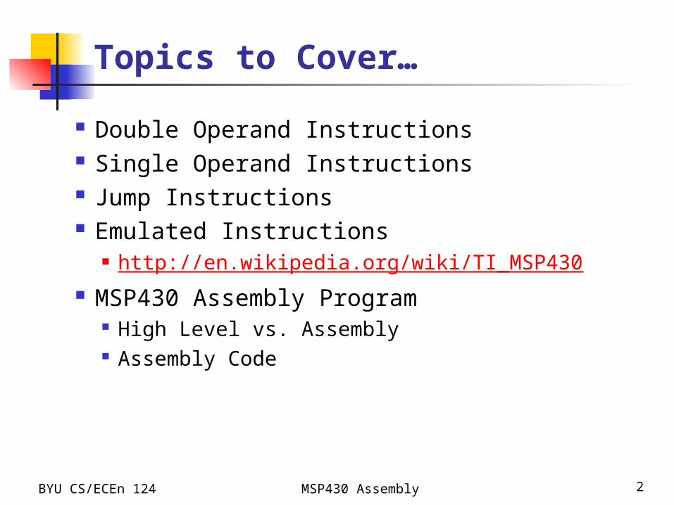
Topics to Cover…
Double Operand Instructions Single Operand Instructions Jump Instructions Emulated Instructions
http://en.wikipedia.org/wiki/TI_MSP430 MSP430 Assembly Program
High Level vs. Assembly Assembly Code
BYU CS/ECEn 124 MSP430 Assembly 3
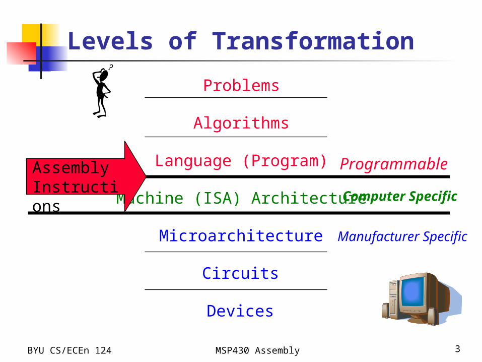
Levels of Transformation
Problems
Algorithms
Language (Program)
Machine (ISA) Architecture
Microarchitecture
Circuits
Devices
Programmable
Computer Specific
Manufacturer Specific
Assembly Instructions
BYU CS/ECEn 124 MSP430 Assembly 4
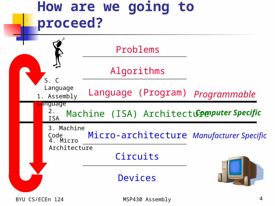
How are we going to proceed?
Problems
Algorithms
Language (Program)
Machine (ISA) Architecture
Micro-architecture
Circuits
Devices
Programmable
Computer Specific
Manufacturer Specific
1. Assembly Language
2. ISA
3. Machine Code
4. Micro Architecture
5. C Language

BYU CS/ECEn 124 MSP430 Assembly 5
Compilation
Algorithm
C-language programc = a + b;
by hand
Machine language programs0100 0100 0000 0101
assembler
Assembly language programADD r4,r5
compiler
to machine for execution
However, low-level assembly language is often used for programming directly.
We will start from assembly language but use high-level C language to help understand it.
Compiler often directly generates machine code.
The assembly language stage is often skipped…
BYU CS/ECEn 124 MSP430 Assembly 6
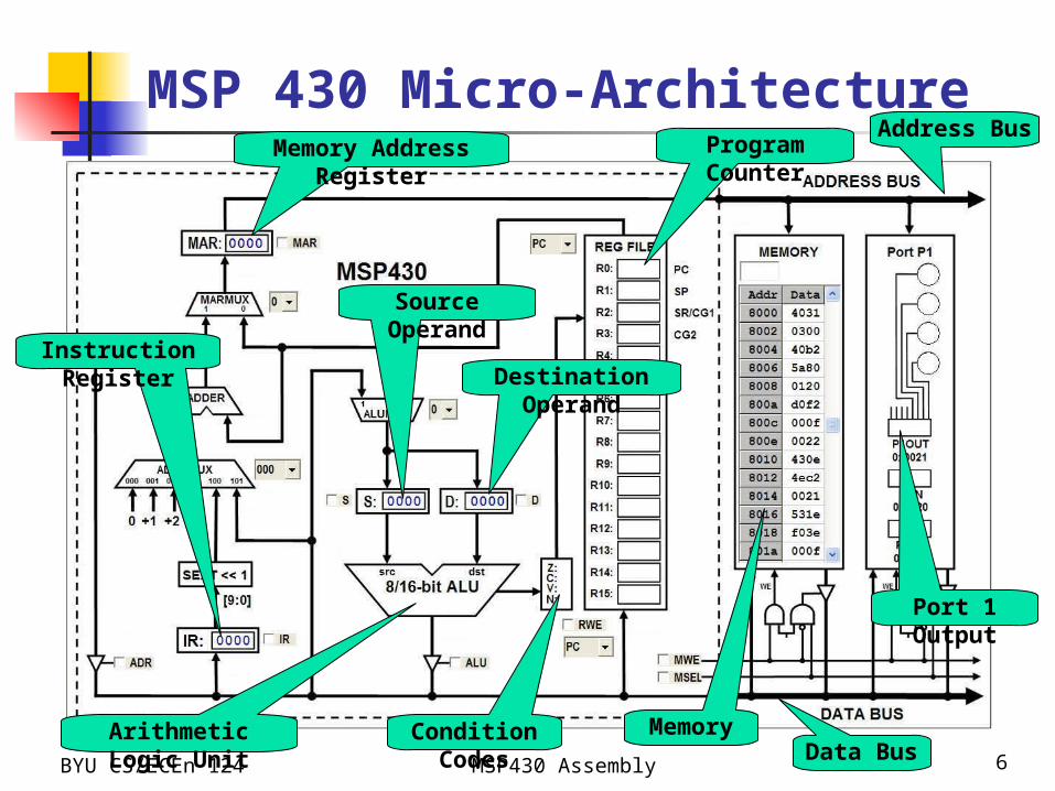
MSP 430 Micro-ArchitectureMemory Address Register
Arithmetic Logic Unit
Program CounterAddress Bus
Data BusCondition Codes Memory
Port 1 Output
Instruction Register
Source Operand
Destination Operand
BYU CS/ECEn 124 MSP430 Assembly 7
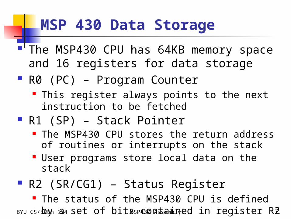
MSP 430 Data Storage
The MSP430 CPU has 64KB memory space and 16 registers for data storage
R0 (PC) – Program Counter This register always points to the next instruction to be
fetched R1 (SP) – Stack Pointer
The MSP430 CPU stores the return address of routines or interrupts on the stack
User programs store local data on the stack R2 (SR/CG1) – Status Register
The status of the MSP430 CPU is defined by a set of bits contained in register R2
BYU CS/ECEn 124 MSP430 Assembly 8
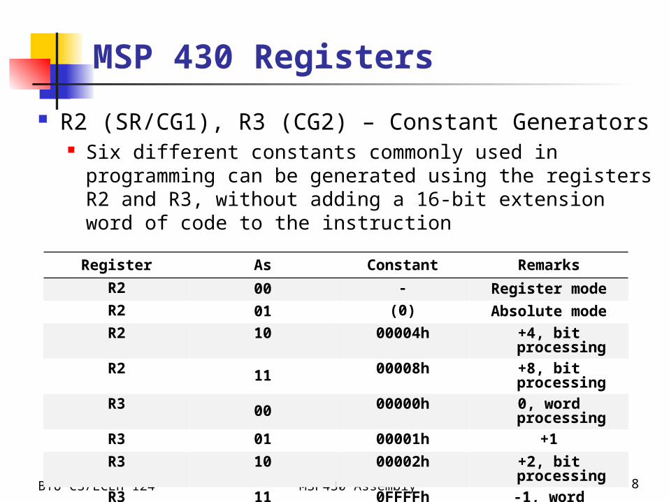
R2 (SR/CG1), R3 (CG2) – Constant Generators Six different constants commonly used in programming
can be generated using the registers R2 and R3, without adding a 16-bit extension word of code to the instruction
Register As Constant Remarks
R2 00 - Register mode
R2 01 (0) Absolute mode
R2 10 00004h +4, bit processing
R2 11 00008h +8, bit processing
R3 00 00000h 0, word processing
R3 01 00001h +1
R3 10 00002h +2, bit processing
R3 11 0FFFFh -1, word processing
MSP 430 Registers
BYU CS/ECEn 124 MSP430 Assembly 9
MSP 430 Registers
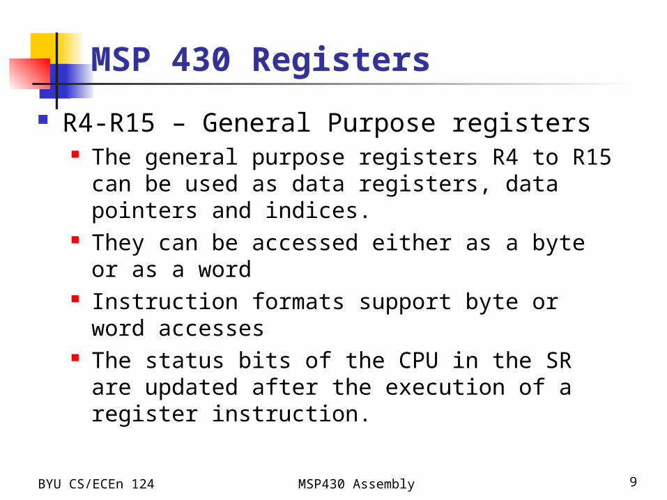
R4-R15 – General Purpose registers The general purpose registers R4 to R15 can be used
as data registers, data pointers and indices. They can be accessed either as a byte or as a word Instruction formats support byte or word accesses The status bits of the CPU in the SR are updated
after the execution of a register instruction.
BYU CS/ECEn 124 MSP430 Assembly 10
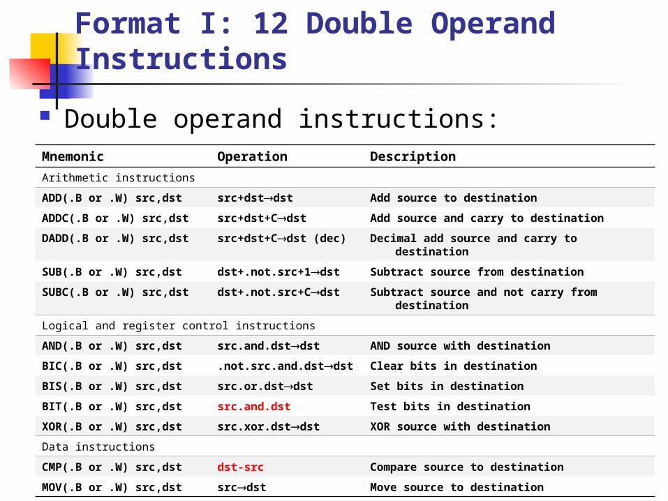
Format I: 12 Double Operand Instructions
Double operand instructions:Mnemonic Operation Description
Arithmetic instructions
ADD(.B or .W) src,dst src+dstdst Add source to destination
ADDC(.B or .W) src,dst src+dst+Cdst Add source and carry to destination
DADD(.B or .W) src,dst src+dst+Cdst (dec) Decimal add source and carry to destination
SUB(.B or .W) src,dst dst+.not.src+1dst Subtract source from destination
SUBC(.B or .W) src,dst dst+.not.src+Cdst Subtract source and not carry from destination
Logical and register control instructions
AND(.B or .W) src,dst src.and.dstdst AND source with destination
BIC(.B or .W) src,dst .not.src.and.dstdst Clear bits in destination
BIS(.B or .W) src,dst src.or.dstdst Set bits in destination
BIT(.B or .W) src,dst src.and.dst Test bits in destination
XOR(.B or .W) src,dst src.xor.dstdst XOR source with destination
Data instructions
CMP(.B or .W) src,dst dst-src Compare source to destination
MOV(.B or .W) src,dst srcdst Move source to destination
BYU CS/ECEn 124 MSP430 Assembly 11
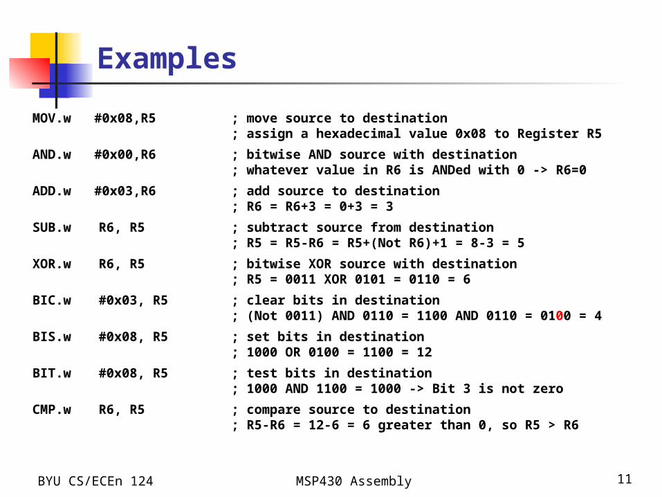
Examples
MOV.w #0x08,R5 ; move source to destination ; assign a hexadecimal value 0x08 to Register R5
AND.w #0x00,R6 ; bitwise AND source with destination ; whatever value in R6 is ANDed with 0 -> R6=0
ADD.w #0x03,R6 ; add source to destination ; R6 = R6+3 = 0+3 = 3
SUB.w R6, R5 ; subtract source from destination; R5 = R5-R6 = R5+(Not R6)+1 = 8-3 = 5
XOR.w R6, R5 ; bitwise XOR source with destination ; R5 = 0011 XOR 0101 = 0110 = 6
BIC.w #0x03, R5 ; clear bits in destination; (Not 0011) AND 0110 = 1100 AND 0110 = 0100 = 4
BIS.w #0x08, R5 ; set bits in destination; 1000 OR 0100 = 1100 = 12
BIT.w #0x08, R5 ; test bits in destination; 1000 AND 1100 = 1000 -> Bit 3 is not zero
CMP.w R6, R5 ; compare source to destination; R5-R6 = 12-6 = 6 greater than 0, so R5 > R6
BYU CS/ECEn 124 MSP430 Assembly 12
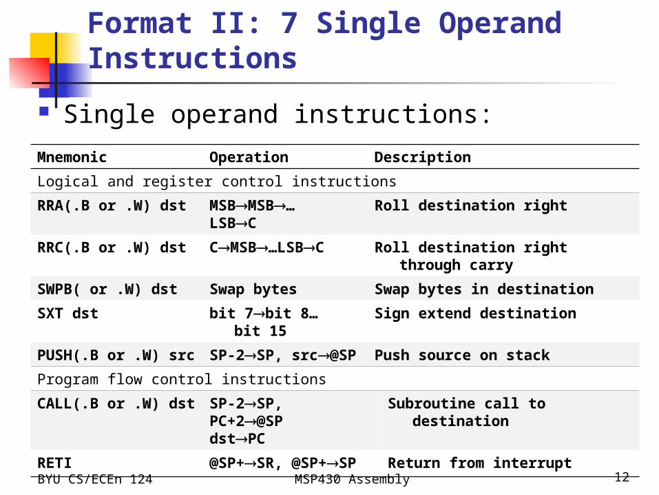
Format II: 7 Single Operand Instructions
Single operand instructions:
Mnemonic Operation Description
Logical and register control instructions
RRA(.B or .W) dst MSBMSB…LSBC
Roll destination right
RRC(.B or .W) dst CMSB…LSBC Roll destination right through carry
SWPB( or .W) dst Swap bytes Swap bytes in destination
SXT dst bit 7bit 8…bit 15 Sign extend destination
PUSH(.B or .W) src SP-2SP, src@SP Push source on stack
Program flow control instructions
CALL(.B or .W) dst SP-2SP,PC+2@SPdstPC
Subroutine call to destination
RETI @SP+SR, @SP+SP Return from interrupt
BYU CS/ECEn 124 MSP430 Assembly 13
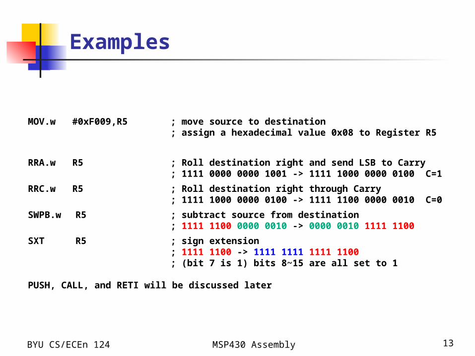
Examples
MOV.w #0xF009,R5 ; move source to destination ; assign a hexadecimal value 0x08 to Register R5
RRA.w R5 ; Roll destination right and send LSB to Carry; 1111 0000 0000 1001 -> 1111 1000 0000 0100
C=1
RRC.w R5 ; Roll destination right through Carry; 1111 1000 0000 0100 -> 1111 1100 0000 0010
C=0
SWPB.w R5 ; subtract source from destination; 1111 1100 0000 0010 -> 0000 0010 1111 1100
SXT R5 ; sign extension; 1111 1100 -> 1111 1111 1111 1100 ; (bit 7 is 1) bits 8~15 are all set to 1
PUSH, CALL, and RETI will be discussed later

BYU CS/ECEn 124 MSP430 Assembly 14
Jump Instruction Format
Jump instructions are used to direct program flow to another part of the program.
The condition on which a jump occurs depends on the Condition field consisting of 3 bits:
JNE/JNZ : jump if not equal JEQ/JZ : jump if equal JNC/JLO : jump if carry flag equal to zero JC/JHS : jump if carry flag equal to one JN : jump if negative (N = 1) JGE : jump if greater than or equal (N = V) JL : jump if lower (less) (N V) JMP : unconditional jump (no condition check)
Jump Instructions
BYU CS/ECEn 124 MSP430 Assembly 15
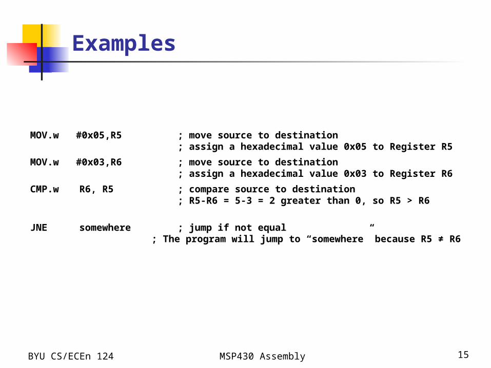
Examples
MOV.w #0x05,R5 ; move source to destination ; assign a hexadecimal value 0x05 to Register R5
MOV.w #0x03,R6 ; move source to destination ; assign a hexadecimal value 0x03 to Register R6
CMP.w R6, R5 ; compare source to destination; R5-R6 = 5-3 = 2 greater than 0, so R5 > R6
JNE somewhere ; jump if not equal ; The program will jump to “somewhere” because R5 ≠ R6
BYU CS/ECEn 124 MSP430 Assembly 16
Emulated Instructions
In addition to the 27 instructions of the CPU there are 24 emulated instructions
The CPU coding is unique The emulated instructions make reading and
writing code easier, but do not have their own op-codes
Emulated instructions are replaced automatically by CPU instructions by the assembler
There are no penalties for using emulated instructions.
Emulated Instructions

BYU CS/ECEn 124 MSP430 Assembly 17
Emulated Instructions
Mnemonic Operation Emulation Description
Arithmetic instructions
ADC(.B or .W) dst dst+Cdst ADDC(.B or .W) #0,dst Add carry to destination
DADC(.B or .W) dst dst+Cdst (decimally)
DADD(.B or .W) #0,dst Decimal add carry to destination
DEC(.B or .W) dst dst-1dst SUB(.B or .W) #1,dst Decrement destination
DECD(.B or .W) dst dst-2dst SUB(.B or .W) #2,dst Decrement destination twice
INC(.B or .W) dst dst+1dst ADD(.B or .W) #1,dst Increment destination
INCD(.B or .W) dst dst+2dst ADD(.B or .W) #2,dst Increment destination twice
SBC(.B or .W) dst dst+0FFFFh+Cdstdst+0FFhdst
SUBC(.B or .W) #0,dst Subtract source and borrow /.NOT. carry from dest.
Emulated Instructions
BYU CS/ECEn 124 MSP430 Assembly 18
Emulated Instructions
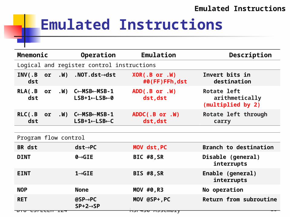
Mnemonic Operation Emulation Description
Logical and register control instructions
INV(.B or .W) dst .NOT.dstdst XOR(.B or .W) #0(FF)FFh,dst
Invert bits in destination
RLA(.B or .W) dst CMSBMSB-1LSB+1LSB0
ADD(.B or .W) dst,dst Rotate left arithmetically(multiplied by 2)
RLC(.B or .W) dst CMSBMSB-1LSB+1LSBC
ADDC(.B or .W) dst,dst Rotate left through carry
Program flow control
BR dst dstPC MOV dst,PC Branch to destination
DINT 0GIE BIC #8,SR Disable (general) interrupts
EINT 1GIE BIS #8,SR Enable (general) interrupts
NOP None MOV #0,R3 No operation
RET @SPPCSP+2SP
MOV @SP+,PC Return from subroutine
Emulated Instructions
BYU CS/ECEn 124 MSP430 Assembly 19
Emulated Instructions
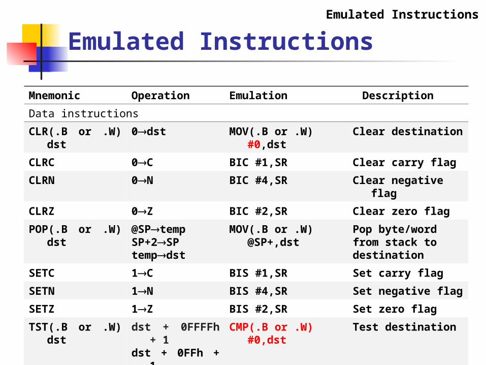
Mnemonic Operation Emulation Description
Data instructions
CLR(.B or .W) dst 0dst MOV(.B or .W) #0,dst Clear destination
CLRC 0C BIC #1,SR Clear carry flag
CLRN 0N BIC #4,SR Clear negative flag
CLRZ 0Z BIC #2,SR Clear zero flag
POP(.B or .W) dst @SPtempSP+2SPtempdst
MOV(.B or .W) @SP+,dst
Pop byte/word from stack to destination
SETC 1C BIS #1,SR Set carry flag
SETN 1N BIS #4,SR Set negative flag
SETZ 1Z BIS #2,SR Set zero flag
TST(.B or .W) dst dst + 0FFFFh + 1dst + 0FFh + 1
CMP(.B or .W) #0,dst Test destination
Emulated Instructions

BYU CS/ECEn 124 MSP430 Assembly 20
Example: Emulated Instructions
Emulated instructions are replaced automatically by CPU instructions by the assembler
Could be replaced differently Clear the contents of register R5:
Increment the content of register R5:
Decmrent the content of register R5:
CLR R5 = MOV.W #0, R5
Emulated Instructions
INC R5 = ADD.W #1, R5
DEC R5 = SUB.W #1, R5

BYU CS/ECEn 124 MSP430 Assembly 21
Decrement by two the contents of register R5:
Do not carry out any operation:
Add the carry flag to the register R5:
DECD R5 = SUB.W #2, R5
Emulated Instructions
NOP = MOV.W R3, R3
ADC R5 = ADC.W #0, R5
Example: Emulated Instructions
BYU CS/ECEn 124 MSP430 Assembly 22
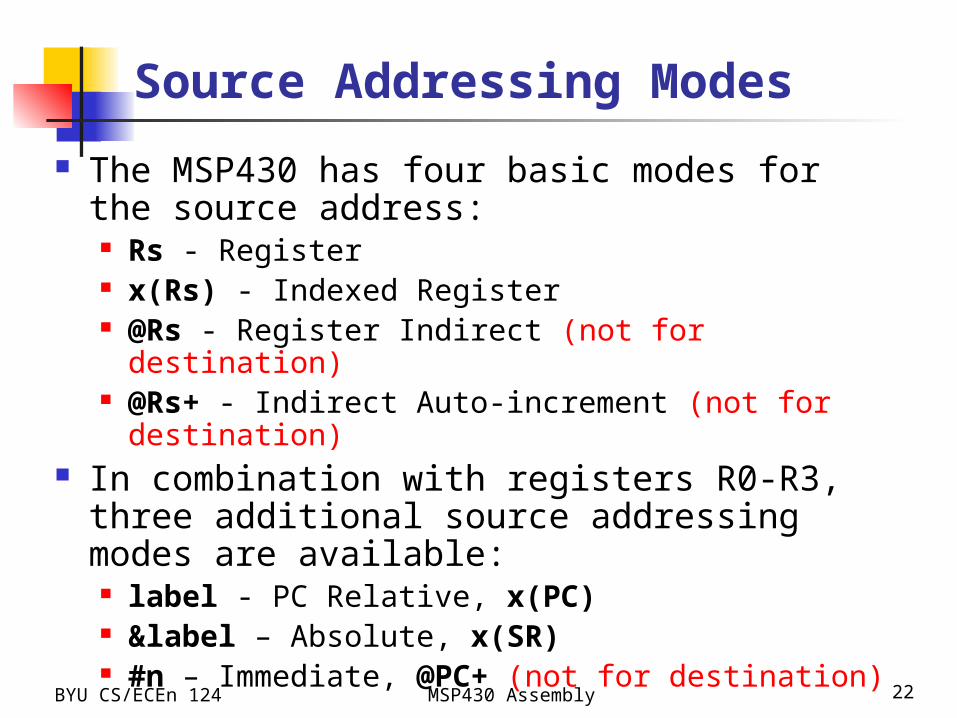
Source Addressing Modes
The MSP430 has four basic modes for the source address: Rs - Register x(Rs) - Indexed Register @Rs - Register Indirect (not for destination) @Rs+ - Indirect Auto-increment (not for destination)
In combination with registers R0-R3, three additional source addressing modes are available: label - PC Relative, x(PC) &label – Absolute, x(SR) #n – Immediate, @PC+ (not for destination)
BYU CS/ECEn 124 Chapter 6 - MSP430 Micro-Architecture 23
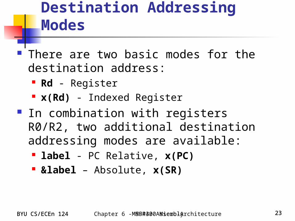
Destination Addressing Modes
There are two basic modes for the destination address: Rd - Register x(Rd) - Indexed Register
In combination with registers R0/R2, two additional destination addressing modes are available: label - PC Relative, x(PC) &label – Absolute, x(SR)
BYU CS/ECEn 124 23MSP430 Assembly
BYU CS/ECEn 124 MSP430 ISA 24
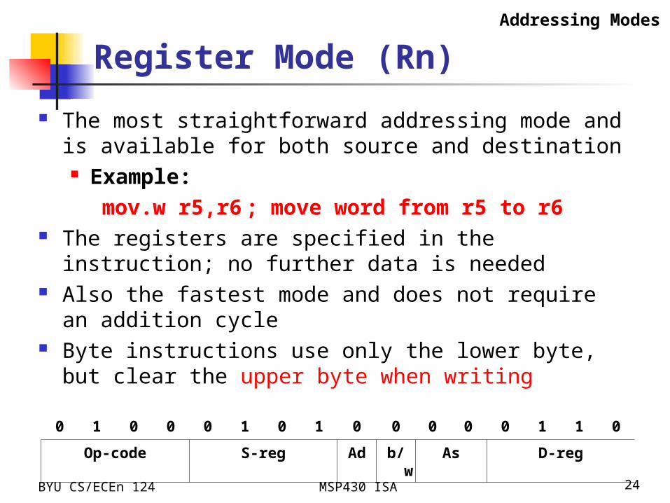
Register Mode (Rn)
The most straightforward addressing mode and is available for both source and destination Example:
mov.w r5,r6 ; move word from r5 to r6 The registers are specified in the instruction; no further
data is needed Also the fastest mode and does not require an addition
cycle Byte instructions use only the lower byte, but clear the
upper byte when writing
Addressing Modes
0 1 0 0 0 1 0 1 0 0 0 0 0 1 1 0
Op-code S-reg Ad b/w As D-reg

BYU CS/ECEn 124 MSP430 ISA 25
Indexed Mode x(Rn)
The address is formed by adding a constant (index) to the contents of a CPU register Example:
mov.b 3(r5),r6 ; move byte from; M(310+r5) to r6
Indexed addressing can be used for source and/or destination, value in r5 is unchanged.
The index is located in the memory word following the instruction and requires an additional memory cycle
There is no restriction on the address for a byte, but words must lie on even addresses
Addressing Modes
0 1 0 0 0 1 0 1 0 1 0 1 0 1 1 0
Op-code S-reg Ad b/w As D-reg
BYU CS/ECEn 124 MSP430 ISA 26
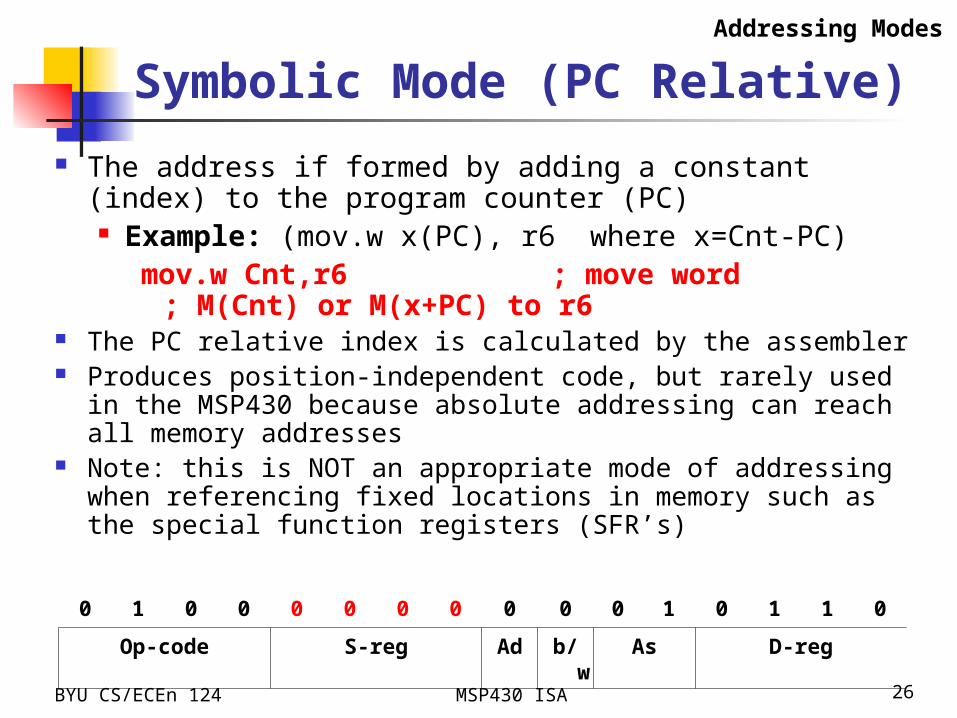
Symbolic Mode (PC Relative)
The address if formed by adding a constant (index) to the program counter (PC) Example: (mov.w x(PC), r6 where x=Cnt-PC)
mov.w Cnt,r6 ; move word; M(Cnt) or M(x+PC) to
r6 The PC relative index is calculated by the assembler Produces position-independent code, but rarely used in the MSP430
because absolute addressing can reach all memory addresses Note: this is NOT an appropriate mode of addressing when
referencing fixed locations in memory such as the special function registers (SFR’s)
Addressing Modes
0 1 0 0 0 0 0 0 0 0 0 1 0 1 1 0
Op-code S-reg Ad b/w As D-reg
BYU CS/ECEn 124 MSP430 ISA 27
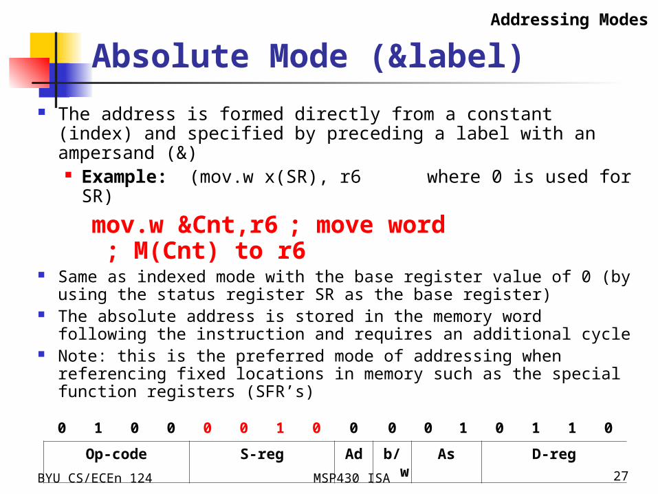
Absolute Mode (&label)
The address is formed directly from a constant (index) and specified by preceding a label with an ampersand (&) Example: (mov.w x(SR), r6 where 0 is used for SR)
mov.w &Cnt,r6 ; move word; M(Cnt) to r6
Same as indexed mode with the base register value of 0 (by using the status register SR as the base register)
The absolute address is stored in the memory word following the instruction and requires an additional cycle
Note: this is the preferred mode of addressing when referencing fixed locations in memory such as the special function registers (SFR’s)
Addressing Modes
0 1 0 0 0 0 1 0 0 0 0 1 0 1 1 0
Op-code S-reg Ad b/w As D-reg
BYU CS/ECEn 124 MSP430 ISA 28
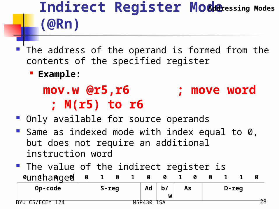
Indirect Register Mode (@Rn)
The address of the operand is formed from the contents of the specified register Example:
mov.w @r5,r6 ; move word; M(r5) to r6
Only available for source operands Same as indexed mode with index equal to 0, but does not
require an additional instruction word The value of the indirect register is unchanged
Addressing Modes
0 1 0 0 0 1 0 1 0 0 1 0 0 1 1 0
Op-code S-reg Ad b/w As D-reg
BYU CS/ECEn 124 MSP430 ISA 29
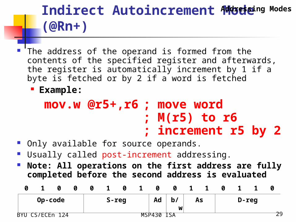
Indirect Autoincrement Mode (@Rn+)
The address of the operand is formed from the contents of the specified register and afterwards, the register is automatically increment by 1 if a byte is fetched or by 2 if a word is fetched Example:
mov.w @r5+,r6 ; move word; M(r5) to r6; increment r5
by 2 Only available for source operands. Usually called post-increment addressing. Note: All operations on the first address are fully completed
before the second address is evaluated
Addressing Modes
0 1 0 0 0 1 0 1 0 0 1 1 0 1 1 0
Op-code S-reg Ad b/w As D-reg

BYU CS/ECEn 124 MSP430 ISA 30
Immediate Mode (#n)
The operand is an immediate value Example (mov.w @PC+, r6)
mov.w #100,r6 ; 100 -> r6 The immediate value is located in the memory word following
the instruction Only available for source operands The immediate mode of addressing is a special case of auto-
increment addressing that uses the program counter (PC) as the source register.
The PC is automatically incremented after the instruction is fetched; hence points to the following word
Addressing Modes
0 1 0 0 0 0 0 0 0 0 1 1 0 1 1 0
Op-code S-reg Ad b/w As D-reg

BYU CS/ECEn 124 MSP430 Assembly 31
mov.w R5, R6 ; move the content of R5 (0010) to R6
mov.w @R7, R8 ; use the content of R7 (9000) as the address to move data (000F) to R8
mov.w &0x9004, R6 ; go to the absolute address (9004) to move data (0011) to R6
mov.w 2(R7), R9 ; use the content of R7 (9000) as the base address and offset it
by 2 (9002) to move data (0010) to R9
mov.w &0x9006, R5 ; go to the absolute address (9006) to move data (0012) to R5
mov.w @R7+, R6 ; use the content of R7 (9000) as the address to move data (000F) to R6 and then increment R7 by 2 (one word is 2 bytes)
mov.w #0x9000, R7 ; move the immediate value (9000) to R7
mov.w label, R7 ; move the data (0012) in the memory space represented by “label” to R7
Examples - Source
000F
0010
0011
0012
0013
x9000
x9002
x9004
x9006
x9008
0010
0020
9000
9004
9006
R5
R6
R7
R8
R9
registers
memory
label:

BYU CS/ECEn 124 MSP430 Assembly 32
mov.w R5, R6 ; move the content of R5 (0010) to R6
mov.w R5, 4(R7) ; use the content of R7 (9000) as the base address and offset it by 4 (9004) and move the content of R5 (0010) to the effective address (9004)
mov.w R6, label ; move the content of R6 (0012 moved from R5) to the memory space represented by “label”
mov.w &0x9004, &0x9008 ; go to the absolute address (9004) to move data (0011) to the memory location of the absolute address (9008)
mov.w R6, &label ; move the content of R6 (0012 moved from R5) to the memory space represented by the absolute address “label”
Examples - Destination
000F
0010
0011
0012
0013
x9000
x9002
x9004
x9006
x9008
0010
0020
9000
9004
9006
R5
R6
R7
R8
R9
registers
memory
label:
BYU CS/ECEn 124 MSP430 Assembly 33
High Level vs. Assembly
High Level Languages More programmer friendly More ISA independent Each high-level statement translates to several
instructions in the ISA of the computer Assembly Languages
Lower level, closer to ISA Very ISA-dependent Each instruction specifies a single ISA instruction Makes low level programming more user friendly More efficient code
High Level vs. Assembly
BYU CS/ECEn 124 MSP430 Assembly 34
Why Assembly Code?
Allows us to work at a slightly higher level than machine language.
Allows us to use symbolic names for opcodes Allows us to use symbolic names for memory
locations - SUM, PRODUCT Don’t need to know every address of every storage
location. Calculates addresses for us – really a big deal! Helps to allocate memory locations. Provides additional error checking
High Level vs. Assembly
The first assembly program
BYU CS/ECEn 124 MSP430 Assembly 35
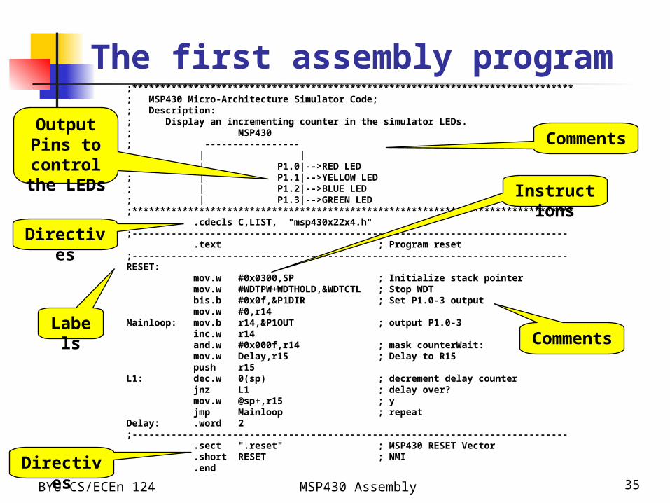
;*******************************************************************************; MSP430 Micro-Architecture Simulator Code;; Description:; Display an incrementing counter in the simulator LEDs.; MSP430; -----------------; | |; | P1.0|-->RED LED; | P1.1|-->YELLOW LED; | P1.2|-->BLUE LED; | P1.3|-->GREEN LED;******************************************************************************* .cdecls C,LIST, "msp430x22x4.h" ;------------------------------------------------------------------------------
.text ; Program reset;------------------------------------------------------------------------------RESET:
mov.w #0x0300,SP ; Initialize stack pointer mov.w #WDTPW+WDTHOLD,&WDTCTL ; Stop WDT bis.b #0x0f,&P1DIR ; Set P1.0-3 output mov.w #0,r14
Mainloop: mov.b r14,&P1OUT ; output P1.0-3 inc.w r14 and.w #0x000f,r14 ; mask counterWait: mov.w Delay,r15 ; Delay to R15 push r15
L1: dec.w 0(sp) ; decrement delay counter jnz L1 ; delay over? mov.w @sp+,r15 ; y jmp Mainloop ; repeat
Delay: .word 2;------------------------------------------------------------------------------
.sect ".reset" ; MSP430 RESET Vector
.short RESET ; NMI
.end
Labels
Directives
Directives
Instructions
Comments
CommentsOutput Pins to control the LEDs

What does it do?
BYU CS/ECEn 124 MSP430 Assembly 36
RESET: mov.w #0x0300,SP ; Initialize stack pointer mov.w #WDTPW+WDTHOLD,&WDTCTL ; Stop WDT bis.b #0x0f,&P1DIR ; Set P1.0-3 output mov.w #0,r14
Mainloop: mov.b r14,&P1OUT ; output P1.0-3 inc.w r14 and.w #0x000f,r14 ; mask counterWait: mov.w Delay,r15 ; Delay to R15 push r15
L1: dec.w 0(sp) ; decrement delay counter jnz L1 ; delay over? mov.w @sp+,r15 ; y jmp Mainloop ; repeat
Delay: .word 2
Move an immediate value #0x0300 into
stack pointer register SP (R1)
Move an immediate value that is the OR’ed result of WDTPW and WDTHOLD (both are
predefined memory addresses) into a memory location at the absolute address
WDTCTL (also a predefined address)
Set the lowest 4 bits of the value stored in the absolute address
location P1DIR to all ‘1’. This is to set Pins 0~3 of Port 1 to be for
output controls (turn LEDs on or off)
Move an immediate value 0 to register #14. 0 is actually
created by hardware
Move the value stored in register #14 to the absolute
address location PIOUT (predefined for Port 1 output
register)Increment value in register #14 by
1 AND the value in register #14 with 0x000F (0000 0000 0000 1111) to keep only the lowest 4 bits in r14.
Move a value “Delay” to r15
Move the value in r15 onto the stack
Decrement the value stored on top of the
stack
If the previous instruction result is NOT zero, then jump
to location labeled L1, else continue to the next
instruction
Move the value stored on top of the stack to r15 and then increment SP
by 2
Unconditionally (always) jump to location labeled Mainloop
.word directive assigned a work value
2 to Delay
BYU CS/ECEn 124 MSP430 Assembly 37
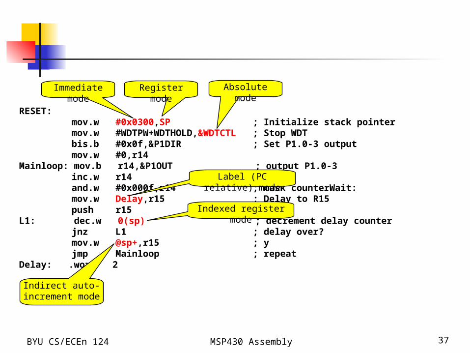
RESET: mov.w #0x0300,SP ; Initialize stack pointer mov.w #WDTPW+WDTHOLD,&WDTCTL ; Stop WDT bis.b #0x0f,&P1DIR ; Set P1.0-3 output mov.w #0,r14
Mainloop: mov.b r14,&P1OUT ; output P1.0-3 inc.w r14 and.w #0x000f,r14 ; mask counterWait: mov.w Delay,r15 ; Delay to R15 push r15
L1: dec.w 0(sp) ; decrement delay counter jnz L1 ; delay over? mov.w @sp+,r15 ; y jmp Mainloop ; repeat
Delay: .word 2
Immediate mode Register mode Absolute mode
Label (PC relative) mode
Indexed register mode
Indirect auto-increment mode
BYU CS/ECEn 124 MSP430 Assembly 38
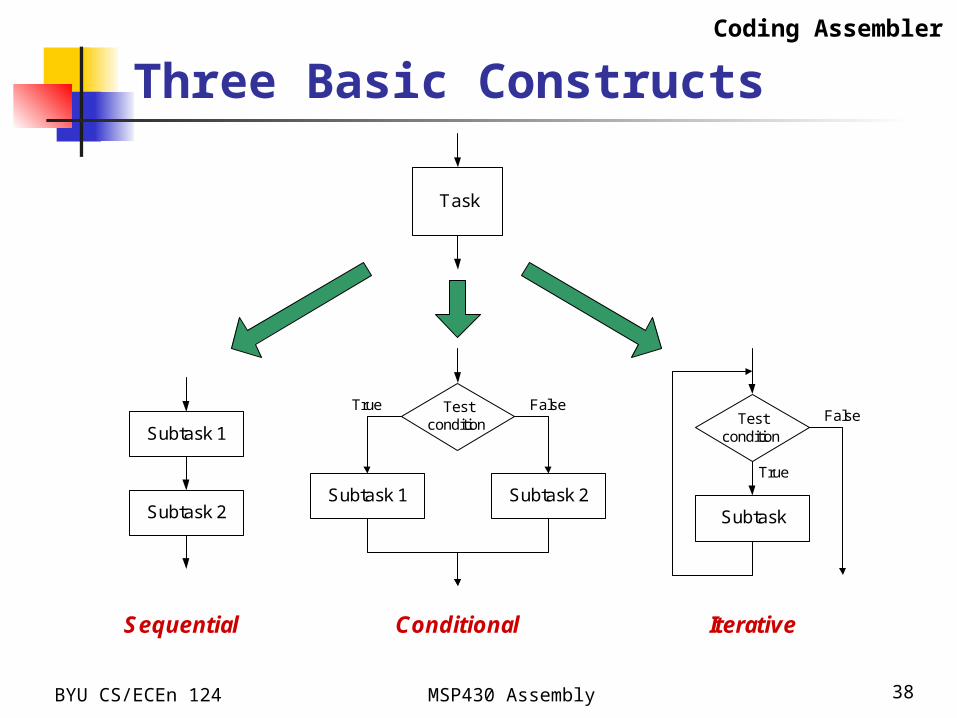
Three Basic Constructs
Task
Subtask 1
Subtask 2Subtask 1 Subtask 2
Testcondition
Subtask
Testcondition
Sequential Conditional Iterative
True
True
FalseFalse
Coding Assembler
BYU CS/ECEn 124 MSP430 Assembly 39
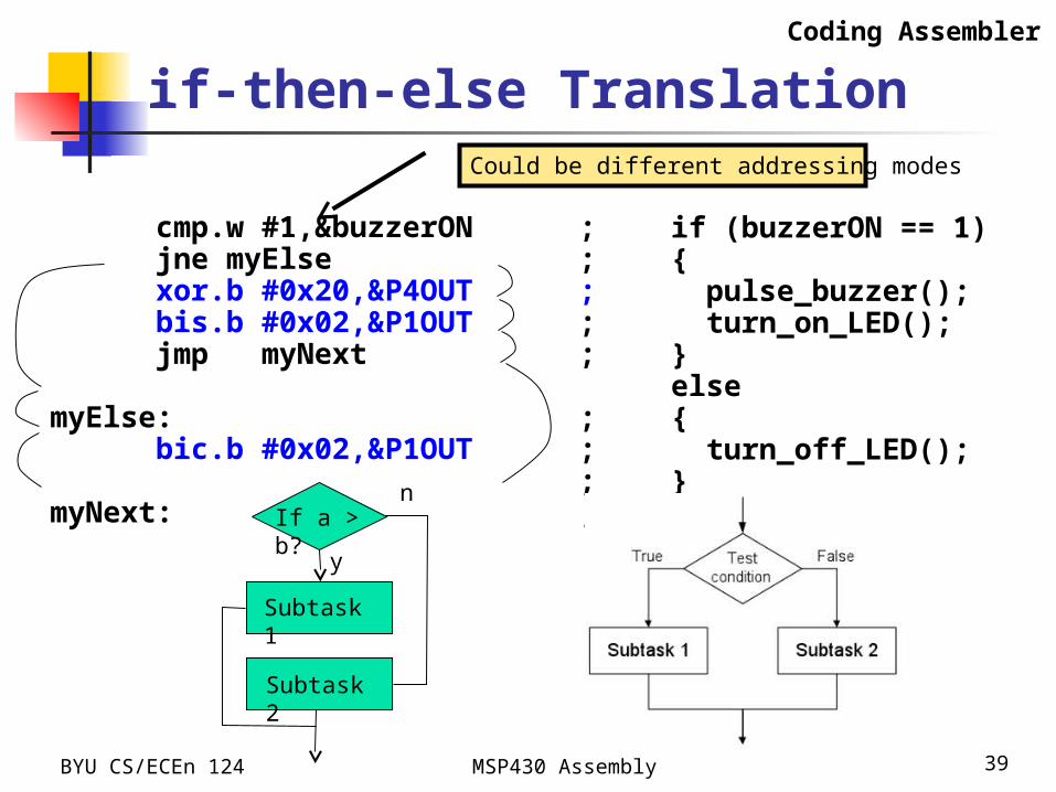
if-then-else Translation
if (buzzerON == 1){ pulse_buzzer(); turn_on_LED();}else{ turn_off_LED();}
cmp.w #1,&buzzerON ; jne myElse ; xor.b #0x20,&P4OUT ; bis.b #0x02,&P1OUT ; jmp myNext ; myElse: ; bic.b #0x02,&P1OUT ; ;myNext: ;
Coding Assembler
Could be different addressing modes
If a > b?
Subtask 1
Subtask 2
n
y
BYU CS/ECEn 124 MSP430 Assembly 40
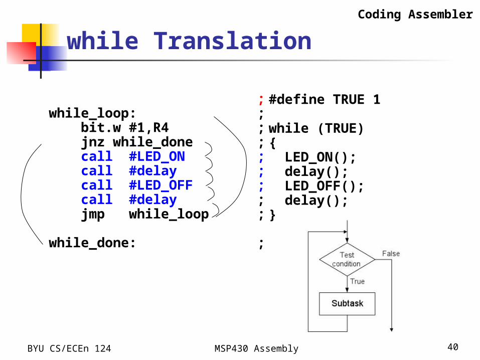
while Translation
#define TRUE 1
while (TRUE){ LED_ON(); delay(); LED_OFF(); delay();}
;while_loop: ; bit.w #1,R4 ; jnz while_done ; call #LED_ON ; call #delay ; call #LED_OFF ; call #delay ; jmp while_loop ;
while_done: ;
Coding Assembler
BYU CS/ECEn 124 MSP430 Assembly 41
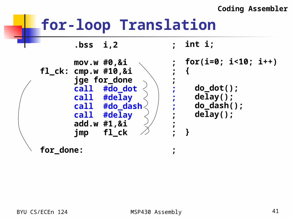
for-loop Translationint i;
for(i=0; i<10; i++){
do_dot(); delay(); do_dash(); delay();
}
.bss i,2 ;
mov.w #0,&i ;fl_ck: cmp.w #10,&i ; jge for_done ; call #do_dot ; call #delay ; call #do_dash ; call #delay ; add.w #1,&i ; jmp fl_ck ;
for_done: ;
Coding Assembler

BYU CS/ECEn 124 MSP430 Assembly 42
switch/case Translation
switch/case
switch (myByte){ case DOT: do_dot(); break;
case DASH: do_dash(); break;
default:}
cmp.w #DOT,&myByte ; jne sw_01 ; call #do_dot ; jmp sw_end ;
sw_01: cmp.w #DASH,&myByte ; jne sw_end ; call #do_dash ; jmp sw_end ; ;sw_end: ;
Coding Assembler
BYU CS/ECEn 124 MSP430 Assembly 43
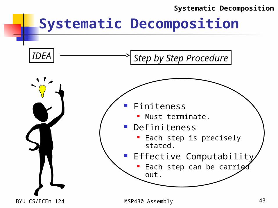
Systematic Decomposition
Finiteness Must terminate.
Definiteness Each step is precisely stated.
Effective Computability Each step can be carried out.
IDEA Step by Step Procedure
Systematic Decomposition
BYU CS/ECEn 124 MSP430 Assembly 44
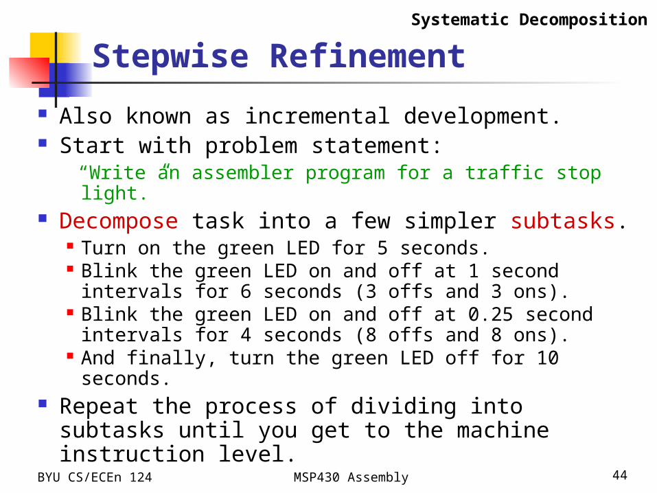
Stepwise Refinement
Also known as incremental development. Start with problem statement:
“Write an assembler program for a traffic stop light.” Decompose task into a few simpler subtasks.
Turn on the green LED for 5 seconds. Blink the green LED on and off at 1 second intervals for
6 seconds (3 offs and 3 ons). Blink the green LED on and off at 0.25 second intervals
for 4 seconds (8 offs and 8 ons). And finally, turn the green LED off for 10 seconds.
Repeat the process of dividing into subtasks until you get to the machine instruction level.
Systematic Decomposition
BYU CS/ECEn 124 MSP430 Assembly 45
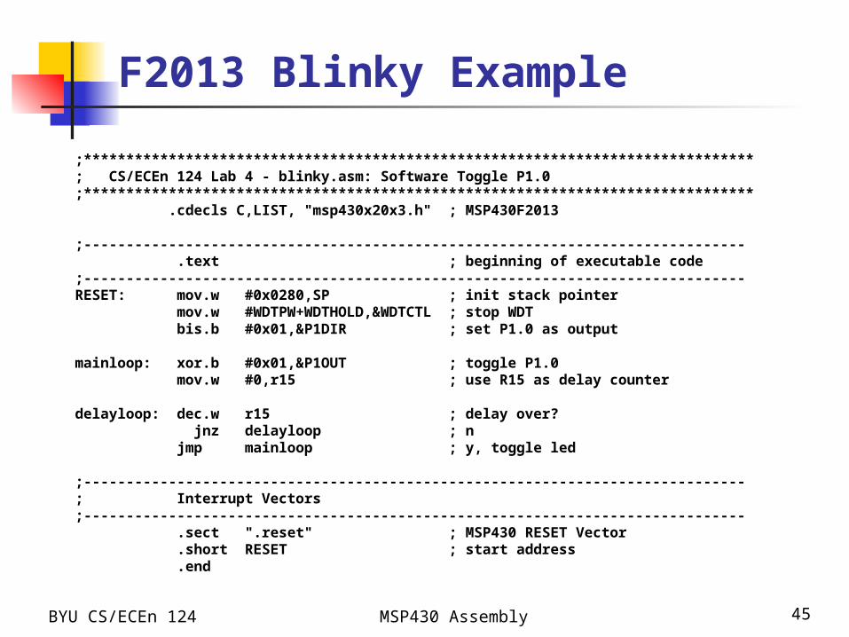
F2013 Blinky Example
;*******************************************************************************; CS/ECEn 124 Lab 4 - blinky.asm: Software Toggle P1.0;******************************************************************************* .cdecls C,LIST, "msp430x20x3.h" ; MSP430F2013
;------------------------------------------------------------------------------ .text ; beginning of executable code;------------------------------------------------------------------------------RESET: mov.w #0x0280,SP ; init stack pointer mov.w #WDTPW+WDTHOLD,&WDTCTL ; stop WDT bis.b #0x01,&P1DIR ; set P1.0 as output
mainloop: xor.b #0x01,&P1OUT ; toggle P1.0 mov.w #0,r15 ; use R15 as delay counter
delayloop: dec.w r15 ; delay over? jnz delayloop ; n jmp mainloop ; y, toggle led
;------------------------------------------------------------------------------; Interrupt Vectors;------------------------------------------------------------------------------ .sect ".reset" ; MSP430 RESET Vector .short RESET ; start address .end

BYU CS/ECEn 124 MSP430 Assembly 46
Add 2nd Delay Loop (not enough);*******************************************************************************; CS/ECEn 124 Lab 4 - blinky.asm: Software Toggle P1.0;******************************************************************************* .cdecls C,LIST, "msp430x20x3.h" ; MSP430F2013delay .set 0;------------------------------------------------------------------------------ .text ; beginning of executable code;------------------------------------------------------------------------------RESET: mov.w #0x0280,SP ; init stack pointer mov.w #WDTPW+WDTHOLD,&WDTCTL ; stop WDT bis.b #0x01,&P1DIR ; set P1.0 as output
mainloop: xor.b #0x01,&P1OUT ; toggle P1.0 mov.w #delay,r15 ; use R15 as delay counter
delayloop: dec.w r15 ; delay over? jnz delayloop ; n r15 goes in negative immediately and
; will stop when it wraps around and returns to 0
delay2: dec.w r15 ; repeat the same loop one more time jnz delay2 jmp mainloop ; y, toggle led
;------------------------------------------------------------------------------; Interrupt Vectors;------------------------------------------------------------------------------ .sect ".reset" ; MSP430 RESET Vector .short RESET ; start address .end
BYU CS/ECEn 124 MSP430 Assembly 47
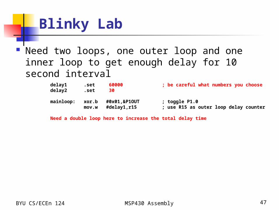
Blinky Lab
Need two loops, one outer loop and one inner loop to get enough delay for 10 second interval
delay1 .set 60000 ; be careful what numbers you choosedelay2 .set 30
mainloop: xor.b #0x01,&P1OUT ; toggle P1.0 mov.w #delay1,r15 ; use R15 as outer loop delay counter
Need a double loop here to increase the total delay time

BYU CS/ECEn 124 MSP430 Assembly 48
Cycles Per Instruction...
Src Dst Cycles Length Example
Rn Rm 1 1 MOV R5,R8
@Rm 2 1 MOV R5,@R6
x(Rm) 4 2 ADD R5,4(R6)
EDE 4 2 XOR R8,EDE
&EDE 4 2 MOV R5,&EDE
#n x(Rm) 5 3 MOV #100,TAB(R8)
&TONI &EDE 6 3 MOV &TONI,&EDE
See “How To Determine Cycles Per Instruction...” in Blinky Lab instructions.
Instruction Timing
BYU CS/ECEn 124 MSP430 Assembly 49
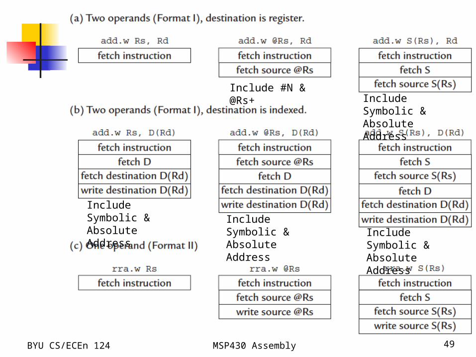
Include #N & @Rs+ Include Symbolic
& Absolute Address
Include Symbolic & Absolute Address
Include Symbolic & Absolute Address
Include Symbolic & Absolute Address
BYU CS/ECEn 124 MSP430 Assembly 50
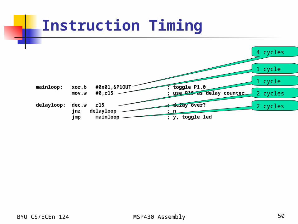
Instruction Timing
mainloop: xor.b #0x01,&P1OUT ; toggle P1.0 mov.w #0,r15 ; use R15 as delay counter
delayloop: dec.w r15 ; delay over? jnz delayloop ; n jmp mainloop ; y, toggle led
4 cycles
1 cycle
1 cycle
2 cycles
2 cycles
BYU CS/ECEn 124 MSP430 Assembly 51
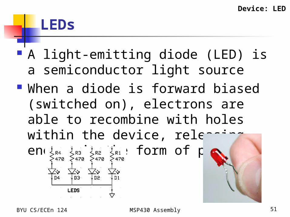
LEDs
A light-emitting diode (LED) is a semiconductor light source
When a diode is forward biased (switched on), electrons are able to recombine with holes within the device, releasing energy in the form of photons
Device: LED
BYU CS/ECEn 124 MSP430 Assembly 52
LEDs
6 LED’s on eZ430X Development Board P1.0 Red LED eZ430-RF2500 P1.1 Green LED eZ430-RF2500 P2.6 LED #1 (Green) P2.7 LED #2 (Orange) P3.3 LED #3 (Yellow) P4.6 LED #4 (Red)
Device: LED

BYU CS/ECEn 124 MSP430 Assembly 53
LEDs
Port bits must be enabled for output by writing a 1 to the port direction register
bis.b #0x03,&P1DIR ; eZ430-RF2500 LED's bic.b #0xc0,&P2SEL ; select GPIO bis.b #0x40,&P2DIR ; LED #1 (P2.6) bis.b #0x80,&P2DIR ; LED #2 (P2.7) bis.b #0x08,&P3DIR ; LED #3 (P3.3) bis.b #0x40,&P4DIR ; LED #4 (P4.6)
Device: LED
0 0 0 0 0 0 1 1
Pin# 7 6 5 4 3 2 1 0
1 0 0 0 0 0 0 0
Pin# 7 6 5 4 3 2 1 0
BYU CS/ECEn 124 MSP430 Assembly 54
LEDs
Turn LED off by writing a 0 to the port pin bic.b #0x03,&P1OUT ; eZ430-RF2500 LED's bic.b #0x40,&P2OUT ; LED #1 (P2.6) bic.b #0x80,&P2OUT ; LED #2 (P2.7) bic.b #0x08,&P3OUT ; LED #3 (P3.3) bic.b #0x40,&P4OUT ; LED #4 (P4.6)
Turn LED on by writing a 1 to the port pin bis.b #0x03,&P1OUT ; eZ430-RF2500 LED's bis.b #0x40,&P2OUT ; LED #1 (P2.6) bis.b #0x80,&P2OUT ; LED #2 (P2.7) bis.b #0x08,&P3OUT ; LED #3 (P3.3) bis.b #0x40,&P4OUT ; LED #4 (P4.6)
Toggle LED by XOR’ing a 1 to the port pin xor.b #0x03,&P1OUT ; eZ430-RF2500 LED's xor.b #0x40,&P2OUT ; LED #1 (P2.6) xor.b #0x80,&P2OUT ; LED #2 (P2.7) xor.b #0x08,&P3OUT ; LED #3 (P3.3) xor.b #0x40,&P4OUT ; LED #4 (P4.6)
Device: LED

BYU CS/ECEn 124 MSP430 Assembly 55