mso70000c, dsa70000c, specification
TRANSCRIPT
xx
MSO70000C, DSA70000C,DPO70000C, DPO7000C,MSO5000, and DPO5000Series OscilloscopesSpecifications and Performance Verification
ZZZ
Technical Reference
*P077006306*
077-0063-06

MSO70000C, DSA70000C,DPO70000C, DPO7000C,MSO5000, and DPO5000Series OscilloscopesSpecifications and Performance Verification
ZZZ
Technical Reference
xx
This document applies to firmware version 6.0.0 and above.
WarningThe servicing instructions are for use by qualified personnelonly. To avoid personal injury, do not perform any servicingunless you are qualified to do so. Refer to all safety summariesprior to performing service.
www.tektronix.com077-0063-06
Copyright © Tektronix. All rights reserved. Licensed software products are owned by Tektronix or its subsidiariesor suppliers, and are protected by national copyright laws and international treaty provisions.
Tektronix products are covered by U.S. and foreign patents, issued and pending. Information in this publicationsupersedes that in all previously published material. Specifications and price change privileges reserved.
TEKTRONIX and TEK are registered trademarks of Tektronix, Inc.
Pinpoint, TekLink, and RT-Eye are registered trademarks of Tektronix, Inc.
Contacting Tektronix
Tektronix, Inc.14150 SW Karl Braun DriveP.O. Box 500Beaverton, OR 97077USA
For product information, sales, service, and technical support:In North America, call 1-800-833-9200.Worldwide, visit www.tektronix.com to find contacts in your area.
Warranty
Tektronix warrants that this product will be free from defects in materials and workmanship for a period of one (1)year from the date of shipment. If any such product proves defective during this warranty period, Tektronix, at itsoption, either will repair the defective product without charge for parts and labor, or will provide a replacementin exchange for the defective product. Parts, modules and replacement products used by Tektronix for warrantywork may be new or reconditioned to like new performance. All replaced parts, modules and products becomethe property of Tektronix.
In order to obtain service under this warranty, Customer must notify Tektronix of the defect before the expiration ofthe warranty period and make suitable arrangements for the performance of service. Customer shall be responsiblefor packaging and shipping the defective product to the service center designated by Tektronix, with shippingcharges prepaid. Tektronix shall pay for the return of the product to Customer if the shipment is to a location withinthe country in which the Tektronix service center is located. Customer shall be responsible for paying all shippingcharges, duties, taxes, and any other charges for products returned to any other locations.
This warranty shall not apply to any defect, failure or damage caused by improper use or improper or inadequatemaintenance and care. Tektronix shall not be obligated to furnish service under this warranty a) to repair damageresulting from attempts by personnel other than Tektronix representatives to install, repair or service the product;b) to repair damage resulting from improper use or connection to incompatible equipment; c) to repair any damageor malfunction caused by the use of non-Tektronix supplies; or d) to service a product that has been modified orintegrated with other products when the effect of such modification or integration increases the time or difficultyof servicing the product.
THIS WARRANTY IS GIVEN BY TEKTRONIX WITH RESPECT TO THE PRODUCT IN LIEU OF ANYOTHER WARRANTIES, EXPRESS OR IMPLIED. TEKTRONIX AND ITS VENDORS DISCLAIM ANYIMPLIED WARRANTIES OF MERCHANTABILITY OR FITNESS FOR A PARTICULAR PURPOSE.TEKTRONIX' RESPONSIBILITY TO REPAIR OR REPLACE DEFECTIVE PRODUCTS IS THE SOLEAND EXCLUSIVE REMEDY PROVIDED TO THE CUSTOMER FOR BREACH OF THIS WARRANTY.TEKTRONIX AND ITS VENDORS WILL NOT BE LIABLE FOR ANY INDIRECT, SPECIAL, INCIDENTAL,OR CONSEQUENTIAL DAMAGES IRRESPECTIVE OF WHETHER TEKTRONIX OR THE VENDOR HASADVANCE NOTICE OF THE POSSIBILITY OF SUCH DAMAGES.
[W2 – 15AUG04]

Table of ContentsGeneral Safety Summary . . . . . . . . . . . . . . . . . . . . . . . . . . . . . . . . . . . . . . . . . . . . . . . . . . . . . . . . . . . . . . . . . . . . . . . . . . . . . . . . . . . . . . . . . vi
Specifications (MSO/DSA/DPO70000C Series and DPO7000C Series)Specifications (MSO/DSA/DPO70000C Series and DPO7000C Series). . . . . . . . . . . . . . . . . . . . . . . . . . . . . . . . . . . 1-1
Specifications (MSO/DPO5000 Series)Specifications (MSO/DPO5000 Series) . . . . . . . . . . . . . . . . . . . . . . . . . . . . . . . . . . . . . . . . . . . . . . . . . . . . . . . . . . . . . . . . . . . . . . . . 2-1
Performance Verification (MSO/DSA/DPO70000C Series and DPO7000CSeries)
Performance Verification (MSO/DSA/DPO70000C Series and DPO7000C Series). . . . . . . . . . . . . . . . . . . . . . 3-1Conventions . . . . . . . . . . . . . . . . . . . . . . . . . . . . . . . . . . . . . . . . . . . . . . . . . . . . . . . . . . . . . . . . . . . . . . . . . . . . . . . . . . . . . . . . . . . . . . . . . . 3-2
Brief Procedures (MSO/DSA/DPO70000C Series and DPO7000C Series) . . . . . . . . . . . . . . . . . . . . . . . . . . . . . . . 3-4Self Tests. . . . . . . . . . . . . . . . . . . . . . . . . . . . . . . . . . . . . . . . . . . . . . . . . . . . . . . . . . . . . . . . . . . . . . . . . . . . . . . . . . . . . . . . . . . . . . . . . . . . . . 3-4Functional Tests. . . . . . . . . . . . . . . . . . . . . . . . . . . . . . . . . . . . . . . . . . . . . . . . . . . . . . . . . . . . . . . . . . . . . . . . . . . . . . . . . . . . . . . . . . . . . . 3-5
Verify All Analog Input Channels . . . . . . . . . . . . . . . . . . . . . . . . . . . . . . . . . . . . . . . . . . . . . . . . . . . . . . . . . . . . . . . . . . . . 3-6Verify the Time Base .. . . . . . . . . . . . . . . . . . . . . . . . . . . . . . . . . . . . . . . . . . . . . . . . . . . . . . . . . . . . . . . . . . . . . . . . . . . . . . . . . . 3-9Verify the A (Main) and B (Delayed) Trigger Systems.. . . . . . . . . . . . . . . . . . . . . . . . . . . . . . . . . . . . . . . . . . 3-12Verify the File System .. . . . . . . . . . . . . . . . . . . . . . . . . . . . . . . . . . . . . . . . . . . . . . . . . . . . . . . . . . . . . . . . . . . . . . . . . . . . . . . 3-13Verify the Digital Channels (MSO70000C Series Only) . . . . . . . . . . . . . . . . . . . . . . . . . . . . . . . . . . . . . . . . . 3-15
Performance Tests (MSO/DSA/DPO70000C Series and DPO7000C Series) . . . . . . . . . . . . . . . . . . . . . . . . . . . 3-18Prerequisites . . . . . . . . . . . . . . . . . . . . . . . . . . . . . . . . . . . . . . . . . . . . . . . . . . . . . . . . . . . . . . . . . . . . . . . . . . . . . . . . . . . . . . . . . . . . . . . . 3-18Equipment Required.. . . . . . . . . . . . . . . . . . . . . . . . . . . . . . . . . . . . . . . . . . . . . . . . . . . . . . . . . . . . . . . . . . . . . . . . . . . . . . . . . . . . . . 3-19Test Record .. . . . . . . . . . . . . . . . . . . . . . . . . . . . . . . . . . . . . . . . . . . . . . . . . . . . . . . . . . . . . . . . . . . . . . . . . . . . . . . . . . . . . . . . . . . . . . . . 3-22Signal Acquisition System Checks . . . . . . . . . . . . . . . . . . . . . . . . . . . . . . . . . . . . . . . . . . . . . . . . . . . . . . . . . . . . . . . . . . . . . . 3-42
Check DC Voltage Measurement Accuracy. . . . . . . . . . . . . . . . . . . . . . . . . . . . . . . . . . . . . . . . . . . . . . . . . . . . . . . . 3-42Check DC Gain Accuracy, ≥ 4 GHz models . . . . . . . . . . . . . . . . . . . . . . . . . . . . . . . . . . . . . . . . . . . . . . . . . . . . . . . 3-48Check Offset Accuracy ≥ 4 GHz models. . . . . . . . . . . . . . . . . . . . . . . . . . . . . . . . . . . . . . . . . . . . . . . . . . . . . . . . . . . 3-56Check Analog Bandwidth, < 3.5 GHz models. . . . . . . . . . . . . . . . . . . . . . . . . . . . . . . . . . . . . . . . . . . . . . . . . . . . . 3-60Check Channel Bandwidth, ≥ 3.5 GHz models. . . . . . . . . . . . . . . . . . . . . . . . . . . . . . . . . . . . . . . . . . . . . . . . . . . . 3-65Check Input Resistance, ≥ 4 GHz models. . . . . . . . . . . . . . . . . . . . . . . . . . . . . . . . . . . . . . . . . . . . . . . . . . . . . . . . . . 3-70
Time Base System Checks. . . . . . . . . . . . . . . . . . . . . . . . . . . . . . . . . . . . . . . . . . . . . . . . . . . . . . . . . . . . . . . . . . . . . . . . . . . . . . . . 3-72Check Timebase and Delay Time Accuracy and Reference. . . . . . . . . . . . . . . . . . . . . . . . . . . . . . . . . . . . . . 3-72Check Delta Time Measurement Accuracy, < 4 GHz models. . . . . . . . . . . . . . . . . . . . . . . . . . . . . . . . . . . . 3-76Check Delta Time Measurement Accuracy, ≥ 4 GHz models. . . . . . . . . . . . . . . . . . . . . . . . . . . . . . . . . . . . 3-80
Trigger System Checks. . . . . . . . . . . . . . . . . . . . . . . . . . . . . . . . . . . . . . . . . . . . . . . . . . . . . . . . . . . . . . . . . . . . . . . . . . . . . . . . . . . . 3-85Check Time Qualified Trigger Accuracy .. . . . . . . . . . . . . . . . . . . . . . . . . . . . . . . . . . . . . . . . . . . . . . . . . . . . . . . . . . 3-85
MSO70000C, DSA70000C, DPO70000C, DPO7000C, MSO5000, DPO5000 Series i
Table of Contents
Check Sensitivity, Edge Trigger, DC Coupled.. . . . . . . . . . . . . . . . . . . . . . . . . . . . . . . . . . . . . . . . . . . . . . . . . . . . 3-89Output Signal Checks .. . . . . . . . . . . . . . . . . . . . . . . . . . . . . . . . . . . . . . . . . . . . . . . . . . . . . . . . . . . . . . . . . . . . . . . . . . . . . . . . . . . . 3-97
Check Aux Trigger Out . . . . . . . . . . . . . . . . . . . . . . . . . . . . . . . . . . . . . . . . . . . . . . . . . . . . . . . . . . . . . . . . . . . . . . . . . . . . . . 3-97Check Probe Compensation or Fast Edge Output . . . . . . . . . . . . . . . . . . . . . . . . . . . . . . . . . . . . . . . . . . . . . . . . . 3-99
Serial Trigger Checks (Optional on Some Models) . . . . . . . . . . . . . . . . . . . . . . . . . . . . . . . . . . . . . . . . . . . . . . . . . . . 3-103Check Serial Trigger Baud Rate Limits . . . . . . . . . . . . . . . . . . . . . . . . . . . . . . . . . . . . . . . . . . . . . . . . . . . . . . . . . . . 3-103Check Serial Trigger Clock Recovery Range. . . . . . . . . . . . . . . . . . . . . . . . . . . . . . . . . . . . . . . . . . . . . . . . . . . . . 3-108
Sine Wave Generator Leveling Procedure . . . . . . . . . . . . . . . . . . . . . . . . . . . . . . . . . . . . . . . . . . . . . . . . . . . . . . . . . . . . . 3-112
Performance Verification (MSO/DPO5000 Series)Performance Verification (MSO/DPO5000 Series) . . . . . . . . . . . . . . . . . . . . . . . . . . . . . . . . . . . . . . . . . . . . . . . . . . . . . . . . . . . 4-1
Test Record .. . . . . . . . . . . . . . . . . . . . . . . . . . . . . . . . . . . . . . . . . . . . . . . . . . . . . . . . . . . . . . . . . . . . . . . . . . . . . . . . . . . . . . . . . . . . . . . . . . 4-2Performance Tests (MSO/DPO5000 Series). . . . . . . . . . . . . . . . . . . . . . . . . . . . . . . . . . . . . . . . . . . . . . . . . . . . . . . . . . . . . . . . . 4-25
Prerequisites . . . . . . . . . . . . . . . . . . . . . . . . . . . . . . . . . . . . . . . . . . . . . . . . . . . . . . . . . . . . . . . . . . . . . . . . . . . . . . . . . . . . . . . . . . . . . . . . 4-25Self Test. . . . . . . . . . . . . . . . . . . . . . . . . . . . . . . . . . . . . . . . . . . . . . . . . . . . . . . . . . . . . . . . . . . . . . . . . . . . . . . . . . . . . . . . . . . . . . . . . . . . . 4-26Check Input Impedance (Resistance) . . . . . . . . . . . . . . . . . . . . . . . . . . . . . . . . . . . . . . . . . . . . . . . . . . . . . . . . . . . . . . . . . . . . 4-27Check DC Balance.. . . . . . . . . . . . . . . . . . . . . . . . . . . . . . . . . . . . . . . . . . . . . . . . . . . . . . . . . . . . . . . . . . . . . . . . . . . . . . . . . . . . . . . . 4-28Check DC Gain Accuracy . . . . . . . . . . . . . . . . . . . . . . . . . . . . . . . . . . . . . . . . . . . . . . . . . . . . . . . . . . . . . . . . . . . . . . . . . . . . . . . . 4-30Check Offset Accuracy. . . . . . . . . . . . . . . . . . . . . . . . . . . . . . . . . . . . . . . . . . . . . . . . . . . . . . . . . . . . . . . . . . . . . . . . . . . . . . . . . . . . 4-33Check Analog Bandwidth.. . . . . . . . . . . . . . . . . . . . . . . . . . . . . . . . . . . . . . . . . . . . . . . . . . . . . . . . . . . . . . . . . . . . . . . . . . . . . . . . 4-35Check Random Noise, Sample Acquisition Mode .. . . . . . . . . . . . . . . . . . . . . . . . . . . . . . . . . . . . . . . . . . . . . . . . . . . . 4-38Check Sample Rate and Delay Time Accuracy . . . . . . . . . . . . . . . . . . . . . . . . . . . . . . . . . . . . . . . . . . . . . . . . . . . . . . . . 4-40Check Delta Time Measurement Accuracy .. . . . . . . . . . . . . . . . . . . . . . . . . . . . . . . . . . . . . . . . . . . . . . . . . . . . . . . . . . . . 4-42Check Digital Threshold Accuracy (MSO5000 only) . . . . . . . . . . . . . . . . . . . . . . . . . . . . . . . . . . . . . . . . . . . . . . . . . 4-44Check Trigger Out . . . . . . . . . . . . . . . . . . . . . . . . . . . . . . . . . . . . . . . . . . . . . . . . . . . . . . . . . . . . . . . . . . . . . . . . . . . . . . . . . . . . . . . . . 4-47
ii MSO70000C, DSA70000C, DPO70000C, DPO7000C, MSO5000, DPO5000 Series
List of FiguresFigure 3-1: Toolbar and menu bar (< 4 GHz models shown). . . . . . . . . . . . . . . . . . . . . . . . . . . . . . . . . . . . . . . . . . . . . . . . 3-3Figure 3-2: Universal test hookup for functional tests - Ch 1 shown.. . . . . . . . . . . . . . . . . . . . . . . . . . . . . . . . . . . . . . 3-6Figure 3-3: Channel button location. . . . . . . . . . . . . . . . . . . . . . . . . . . . . . . . . . . . . . . . . . . . . . . . . . . . . . . . . . . . . . . . . . . . . . . . . . . . 3-7Figure 3-4: Setup for time base test . . . . . . . . . . . . . . . . . . . . . . . . . . . . . . . . . . . . . . . . . . . . . . . . . . . . . . . . . . . . . . . . . . . . . . . . . . 3-10Figure 3-5: Setup for trigger test. . . . . . . . . . . . . . . . . . . . . . . . . . . . . . . . . . . . . . . . . . . . . . . . . . . . . . . . . . . . . . . . . . . . . . . . . . . . . . 3-12Figure 3-6: Setup for the file system test . . . . . . . . . . . . . . . . . . . . . . . . . . . . . . . . . . . . . . . . . . . . . . . . . . . . . . . . . . . . . . . . . . . . 3-14Figure 3-7: Setup for the digital channels test. . . . . . . . . . . . . . . . . . . . . . . . . . . . . . . . . . . . . . . . . . . . . . . . . . . . . . . . . . . . . . . 3-15Figure 3-8: Initial test hookup . . . . . . . . . . . . . . . . . . . . . . . . . . . . . . . . . . . . . . . . . . . . . . . . . . . . . . . . . . . . . . . . . . . . . . . . . . . . . . . . 3-43Figure 3-9: Measurement of DC accuracy at maximum offset and position.. . . . . . . . . . . . . . . . . . . . . . . . . . . . 3-46Figure 3-10: Measurement of DC gain accuracy .. . . . . . . . . . . . . . . . . . . . . . . . . . . . . . . . . . . . . . . . . . . . . . . . . . . . . . . . . . 3-55Figure 3-11: Initial test hookup .. . . . . . . . . . . . . . . . . . . . . . . . . . . . . . . . . . . . . . . . . . . . . . . . . . . . . . . . . . . . . . . . . . . . . . . . . . . . . . 3-56Figure 3-12: Measurement of offset accuracy.. . . . . . . . . . . . . . . . . . . . . . . . . . . . . . . . . . . . . . . . . . . . . . . . . . . . . . . . . . . . . . 3-58Figure 3-13: Initial test hookup .. . . . . . . . . . . . . . . . . . . . . . . . . . . . . . . . . . . . . . . . . . . . . . . . . . . . . . . . . . . . . . . . . . . . . . . . . . . . . . 3-61Figure 3-14: Measurement of analog bandwidth .. . . . . . . . . . . . . . . . . . . . . . . . . . . . . . . . . . . . . . . . . . . . . . . . . . . . . . . . . . 3-63Figure 3-15: Initial test hookup .. . . . . . . . . . . . . . . . . . . . . . . . . . . . . . . . . . . . . . . . . . . . . . . . . . . . . . . . . . . . . . . . . . . . . . . . . . . . . . 3-66Figure 3-16: Measurement of analog bandwidth .. . . . . . . . . . . . . . . . . . . . . . . . . . . . . . . . . . . . . . . . . . . . . . . . . . . . . . . . . . 3-69Figure 3-17: Initial test hookup .. . . . . . . . . . . . . . . . . . . . . . . . . . . . . . . . . . . . . . . . . . . . . . . . . . . . . . . . . . . . . . . . . . . . . . . . . . . . . . 3-70Figure 3-18: Initial test hookup .. . . . . . . . . . . . . . . . . . . . . . . . . . . . . . . . . . . . . . . . . . . . . . . . . . . . . . . . . . . . . . . . . . . . . . . . . . . . . . 3-72Figure 3-19: Initial test hookup .. . . . . . . . . . . . . . . . . . . . . . . . . . . . . . . . . . . . . . . . . . . . . . . . . . . . . . . . . . . . . . . . . . . . . . . . . . . . . . 3-73Figure 3-20: Final test hookup . . . . . . . . . . . . . . . . . . . . . . . . . . . . . . . . . . . . . . . . . . . . . . . . . . . . . . . . . . . . . . . . . . . . . . . . . . . . . . . . 3-74Figure 3-21: Delta time accuracy test hookup.. . . . . . . . . . . . . . . . . . . . . . . . . . . . . . . . . . . . . . . . . . . . . . . . . . . . . . . . . . . . . . 3-76Figure 3-22: Delta time accuracy test hookup.. . . . . . . . . . . . . . . . . . . . . . . . . . . . . . . . . . . . . . . . . . . . . . . . . . . . . . . . . . . . . . 3-80Figure 3-23: Initial test hookup .. . . . . . . . . . . . . . . . . . . . . . . . . . . . . . . . . . . . . . . . . . . . . . . . . . . . . . . . . . . . . . . . . . . . . . . . . . . . . . 3-85Figure 3-24: Measurement of time accuracy for pulse and glitch triggering . . . . . . . . . . . . . . . . . . . . . . . . . . . . 3-86Figure 3-25: Initial test hookup .. . . . . . . . . . . . . . . . . . . . . . . . . . . . . . . . . . . . . . . . . . . . . . . . . . . . . . . . . . . . . . . . . . . . . . . . . . . . . . 3-90Figure 3-26: Measurement of trigger sensitivity - 50 MHz results shown .. . . . . . . . . . . . . . . . . . . . . . . . . . . . . . 3-92Figure 3-27: Initial test hookup .. . . . . . . . . . . . . . . . . . . . . . . . . . . . . . . . . . . . . . . . . . . . . . . . . . . . . . . . . . . . . . . . . . . . . . . . . . . . . . 3-97Figure 3-28: Measurement of trigger out limits. . . . . . . . . . . . . . . . . . . . . . . . . . . . . . . . . . . . . . . . . . . . . . . . . . . . . . . . . . . . . 3-98Figure 3-29: Initial test hookup .. . . . . . . . . . . . . . . . . . . . . . . . . . . . . . . . . . . . . . . . . . . . . . . . . . . . . . . . . . . . . . . . . . . . . . . . . . . . . . 3-99Figure 3-30: Measurement of probe compensator frequency. . . . . . . . . . . . . . . . . . . . . . . . . . . . . . . . . . . . . . . . . . . . . 3-100Figure 3-31: Subsequent test hookup . . . . . . . . . . . . . . . . . . . . . . . . . . . . . . . . . . . . . . . . . . . . . . . . . . . . . . . . . . . . . . . . . . . . . . . 3-101Figure 3-32: Measurement of probe compensator amplitude. . . . . . . . . . . . . . . . . . . . . . . . . . . . . . . . . . . . . . . . . . . . . 3-101Figure 3-33: Initial test hookup .. . . . . . . . . . . . . . . . . . . . . . . . . . . . . . . . . . . . . . . . . . . . . . . . . . . . . . . . . . . . . . . . . . . . . . . . . . . . . 3-103Figure 3-34: Isolated 0 triggering.. . . . . . . . . . . . . . . . . . . . . . . . . . . . . . . . . . . . . . . . . . . . . . . . . . . . . . . . . . . . . . . . . . . . . . . . . . . 3-105Figure 3-35: Isolated 1 triggering.. . . . . . . . . . . . . . . . . . . . . . . . . . . . . . . . . . . . . . . . . . . . . . . . . . . . . . . . . . . . . . . . . . . . . . . . . . . 3-107Figure 3-36: Initial test hookup .. . . . . . . . . . . . . . . . . . . . . . . . . . . . . . . . . . . . . . . . . . . . . . . . . . . . . . . . . . . . . . . . . . . . . . . . . . . . . 3-108Figure 3-37: Clock recovery . . . . . . . . . . . . . . . . . . . . . . . . . . . . . . . . . . . . . . . . . . . . . . . . . . . . . . . . . . . . . . . . . . . . . . . . . . . . . . . . . 3-111Figure 3-38: Sine wave generator leveling equipment setup . . . . . . . . . . . . . . . . . . . . . . . . . . . . . . . . . . . . . . . . . . . . . 3-112Figure 3-39: Equipment setup for maximum amplitude .. . . . . . . . . . . . . . . . . . . . . . . . . . . . . . . . . . . . . . . . . . . . . . . . . 3-114
MSO70000C, DSA70000C, DPO70000C, DPO7000C, MSO5000, DPO5000 Series iii
Table of Contents
List of TablesTable 1-1: Channel input and vertical specifications, all MSO/DSA/DPO70000C and DPO7000C Series
models. . . . . . . . . . . . . . . . . . . . . . . . . . . . . . . . . . . . . . . . . . . . . . . . . . . . . . . . . . . . . . . . . . . . . . . . . . . . . . . . . . . . . . . . . . . . . . . . . . . . . . . . . 1-1Table 1-2: Horizontal and acquisition system specifications, all MSO/DSA/DPO70000C and DPO7000C
Series models. . . . . . . . . . . . . . . . . . . . . . . . . . . . . . . . . . . . . . . . . . . . . . . . . . . . . . . . . . . . . . . . . . . . . . . . . . . . . . . . . . . . . . . . . . . . . . . 1-41Table 1-3: Trigger specifications, all MSO/DSA/DPO70000C and DPO7000C Series models . . . . . . . 1-48Table 1-4: Serial Trigger specifications, all MSO/DSA/DPO70000C Series models (optional on
DPO7000C models) . . . . . . . . . . . . . . . . . . . . . . . . . . . . . . . . . . . . . . . . . . . . . . . . . . . . . . . . . . . . . . . . . . . . . . . . . . . . . . . . . . . . . . . 1-55Table 1-5: Digital acquisition specifications (MSO70000C Series) . . . . . . . . . . . . . . . . . . . . . . . . . . . . . . . . . . . . . . 1-57Table 1-6: Input/output port specifications, all MSO/DSA/DPO70000C and DPO7000C Series
models. . . . . . . . . . . . . . . . . . . . . . . . . . . . . . . . . . . . . . . . . . . . . . . . . . . . . . . . . . . . . . . . . . . . . . . . . . . . . . . . . . . . . . . . . . . . . . . . . . . . . . . 1-58Table 1-7: Data storage specifications, all MSO/DSA/DPO70000C and DPO7000C Series models . 1-61Table 1-8: Power source specification, all MSO/DSA/DPO70000C and DPO7000C Series models . 1-61Table 1-9: Mechanical specifications, all MSO/DSA/DPO70000C and DPO7000C Series models . . 1-62Table 1-10: Environmental specifications, all MSO/DSA/DPO70000C and DPO7000C Series
models. . . . . . . . . . . . . . . . . . . . . . . . . . . . . . . . . . . . . . . . . . . . . . . . . . . . . . . . . . . . . . . . . . . . . . . . . . . . . . . . . . . . . . . . . . . . . . . . . . . . . . . 1-63Table 2-1: Analog channel input and vertical specification. . . . . . . . . . . . . . . . . . . . . . . . . . . . . . . . . . . . . . . . . . . . . . . . . . 2-1Table 2-2: Horizontal and acquisition system specifications . . . . . . . . . . . . . . . . . . . . . . . . . . . . . . . . . . . . . . . . . . . . . . . . 2-9Table 2-3: Trigger specifications. . . . . . . . . . . . . . . . . . . . . . . . . . . . . . . . . . . . . . . . . . . . . . . . . . . . . . . . . . . . . . . . . . . . . . . . . . . . . . 2-11Table 2-4: Digital acquisition specifications, MSO5000 Series . . . . . . . . . . . . . . . . . . . . . . . . . . . . . . . . . . . . . . . . . . 2-15Table 2-5: P6616 Digital Probe specifications . . . . . . . . . . . . . . . . . . . . . . . . . . . . . . . . . . . . . . . . . . . . . . . . . . . . . . . . . . . . . . 2-15Table 2-6: Display specifications . . . . . . . . . . . . . . . . . . . . . . . . . . . . . . . . . . . . . . . . . . . . . . . . . . . . . . . . . . . . . . . . . . . . . . . . . . . . . 2-16Table 2-7: Input/Output port specifications. . . . . . . . . . . . . . . . . . . . . . . . . . . . . . . . . . . . . . . . . . . . . . . . . . . . . . . . . . . . . . . . . . 2-16Table 2-8: Data storage specifications. . . . . . . . . . . . . . . . . . . . . . . . . . . . . . . . . . . . . . . . . . . . . . . . . . . . . . . . . . . . . . . . . . . . . . . . 2-17Table 2-9: Power source specifications . . . . . . . . . . . . . . . . . . . . . . . . . . . . . . . . . . . . . . . . . . . . . . . . . . . . . . . . . . . . . . . . . . . . . . 2-17Table 2-10: Environmental specifications . . . . . . . . . . . . . . . . . . . . . . . . . . . . . . . . . . . . . . . . . . . . . . . . . . . . . . . . . . . . . . . . . . . 2-17Table 2-11: Mechanical specifications . . . . . . . . . . . . . . . . . . . . . . . . . . . . . . . . . . . . . . . . . . . . . . . . . . . . . . . . . . . . . . . . . . . . . . . 2-18Table 3-1: Vertical settings . . . . . . . . . . . . . . . . . . . . . . . . . . . . . . . . . . . . . . . . . . . . . . . . . . . . . . . . . . . . . . . . . . . . . . . . . . . . . . . . . . . . . . 3-8Table 3-2: Test equipment . . . . . . . . . . . . . . . . . . . . . . . . . . . . . . . . . . . . . . . . . . . . . . . . . . . . . . . . . . . . . . . . . . . . . . . . . . . . . . . . . . . . . 3-19Table 3-3: Test record . . . . . . . . . . . . . . . . . . . . . . . . . . . . . . . . . . . . . . . . . . . . . . . . . . . . . . . . . . . . . . . . . . . . . . . . . . . . . . . . . . . . . . . . . . 3-23Table 3-4: DC voltage measurement accuracy . . . . . . . . . . . . . . . . . . . . . . . . . . . . . . . . . . . . . . . . . . . . . . . . . . . . . . . . . . . . . . 3-44Table 3-5: Gain accuracy . . . . . . . . . . . . . . . . . . . . . . . . . . . . . . . . . . . . . . . . . . . . . . . . . . . . . . . . . . . . . . . . . . . . . . . . . . . . . . . . . . . . . . 3-49Table 3-6: Offset accuracy.. . . . . . . . . . . . . . . . . . . . . . . . . . . . . . . . . . . . . . . . . . . . . . . . . . . . . . . . . . . . . . . . . . . . . . . . . . . . . . . . . . . . 3-57Table 3-7: Analog bandwidth, < 3.5 GHz models . . . . . . . . . . . . . . . . . . . . . . . . . . . . . . . . . . . . . . . . . . . . . . . . . . . . . . . . . . 3-62Table 3-8: Channel bandwidth ≥4 GHz models. . . . . . . . . . . . . . . . . . . . . . . . . . . . . . . . . . . . . . . . . . . . . . . . . . . . . . . . . . . . . 3-67Table 3-9: Channel bandwidth 3.5 GHz model . . . . . . . . . . . . . . . . . . . . . . . . . . . . . . . . . . . . . . . . . . . . . . . . . . . . . . . . . . . . . 3-67Table 3-10: Delta time measurement settings . . . . . . . . . . . . . . . . . . . . . . . . . . . . . . . . . . . . . . . . . . . . . . . . . . . . . . . . . . . . . . . 3-78Table 3-11: Delta time measurement settings . . . . . . . . . . . . . . . . . . . . . . . . . . . . . . . . . . . . . . . . . . . . . . . . . . . . . . . . . . . . . . . 3-81Table 3-12: Trigger settings for ≥ 4 GHz models . . . . . . . . . . . . . . . . . . . . . . . . . . . . . . . . . . . . . . . . . . . . . . . . . . . . . . . . . . . 3-94Table 3-13: Serial pattern data . . . . . . . . . . . . . . . . . . . . . . . . . . . . . . . . . . . . . . . . . . . . . . . . . . . . . . . . . . . . . . . . . . . . . . . . . . . . . . . 3-104
iv MSO70000C, DSA70000C, DPO70000C, DPO7000C, MSO5000, DPO5000 Series

Table of Contents
Table 3-14: Word recognizer data . . . . . . . . . . . . . . . . . . . . . . . . . . . . . . . . . . . . . . . . . . . . . . . . . . . . . . . . . . . . . . . . . . . . . . . . . . . 3-106Table 3-15: Clock recovery input frequencies and baud rates . . . . . . . . . . . . . . . . . . . . . . . . . . . . . . . . . . . . . . . . . . . . 3-110Table 4-1: Required equipment . . . . . . . . . . . . . . . . . . . . . . . . . . . . . . . . . . . . . . . . . . . . . . . . . . . . . . . . . . . . . . . . . . . . . . . . . . . . . . . . . 4-1Table 4-2: Gain expected worksheet . . . . . . . . . . . . . . . . . . . . . . . . . . . . . . . . . . . . . . . . . . . . . . . . . . . . . . . . . . . . . . . . . . . . . . . . . 4-31Table 4-3: Maximum bandwidth frequency worksheet . . . . . . . . . . . . . . . . . . . . . . . . . . . . . . . . . . . . . . . . . . . . . . . . . . . . 4-37
MSO70000C, DSA70000C, DPO70000C, DPO7000C, MSO5000, DPO5000 Series v
General Safety Summary
General Safety SummaryReview the following safety precautions to avoid injury and prevent damage tothis product or any products connected to it.
To avoid potential hazards, use this product only as specified.
Only qualified personnel should perform service procedures.
While using this product, you may need to access other parts of a larger system.Read the safety sections of the other component manuals for warnings andcautions related to operating the system.
To Avoid Fire or PersonalInjury
Use proper power cord. Use only the power cord specified for this product andcertified for the country of use.
Connect and disconnect properly. Do not connect or disconnect probes or testleads while they are connected to a voltage source.
Ground the product. This product is grounded through the grounding conductorof the power cord. To avoid electric shock, the grounding conductor must beconnected to earth ground. Before making connections to the input or outputterminals of the product, ensure that the product is properly grounded.
Observe all terminal ratings. To avoid fire or shock hazard, observe all ratingsand markings on the product. Consult the product manual for further ratingsinformation before making connections to the product.
The inputs are not rated for connection to mains or Category II, III, or IV circuits.
Connect the probe reference lead to earth ground only.
Power disconnect. The power cord disconnects the product from the power source.Do not block the power cord; it must remain accessible to the user at all times.
Do not operate without covers. Do not operate this product with covers or panelsremoved.
Do not operate with suspected failures. If you suspect that there is damage to thisproduct, have it inspected by qualified service personnel.
Avoid exposed circuitry. Do not touch exposed connections and components whenpower is present.
Do not operate in wet/damp conditions.
Do not operate in an explosive atmosphere.
Keep product surfaces clean and dry.
Provide proper ventilation. Refer to the manual's installation instructions for detailson installing the product so it has proper ventilation.
vi MSO70000C, DSA70000C, DPO70000C, DPO7000C, MSO5000, DPO5000 Series
General Safety Summary
Terms in This Manual These terms may appear in this manual:
WARNING. Warning statements identify conditions or practices that could resultin injury or loss of life.
CAUTION. Caution statements identify conditions or practices that could result indamage to this product or other property.
Symbols and Terms on theProduct
These terms may appear on the product:
DANGER indicates an injury hazard immediately accessible as you readthe marking.
WARNING indicates an injury hazard not immediately accessible as youread the marking.
CAUTION indicates a hazard to property including the product.
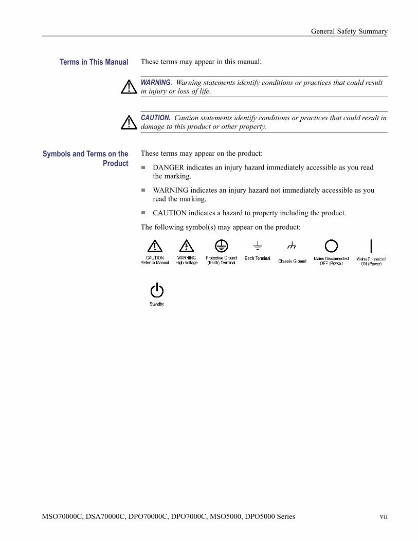
The following symbol(s) may appear on the product:
MSO70000C, DSA70000C, DPO70000C, DPO7000C, MSO5000, DPO5000 Series vii

General Safety Summary
viii MSO70000C, DSA70000C, DPO70000C, DPO7000C, MSO5000, DPO5000 Series

Specifications (MSO/DSA/DPO70000CSeries and DPO7000C Series)

Specifications (MSO/DSA/DPO70000C Series andDPO7000C Series)
This chapter contains the specifications for the instrument. All specifications areguaranteed unless labeled "typical." Typical specifications are provided for yourconvenience but are not guaranteed. Specifications that are marked with thesymbol are checked in this manual. All specifications apply to all models unlessnoted otherwise.
≥ 4 GHz models specifications apply to MSO70000C, DSA70000C, andDPO70000C Series instruments unless noted otherwise.
< 4 GHz models specifications apply to the DPO7000C Series instruments unlessnoted otherwise.
To meet specifications, the following conditions must be met:
The instrument must have been calibrated in an ambient temperature between18 °C and 28 °C (64 °F and 82 °F).
The instrument must be operating within the environmental limits. (Seepage 1-63.)
The instrument must be powered from a source that meets the specifications.(See page 2-17.)
The instrument must have been operating continuously for at least 20 minuteswithin the specified operating temperature range.
You must perform the Signal Path Compensation procedure after the20-minute warm-up period. See the online help for instructions on how toperform signal path compensation. If the ambient temperature changes morethan 5 °C, repeat the procedure.
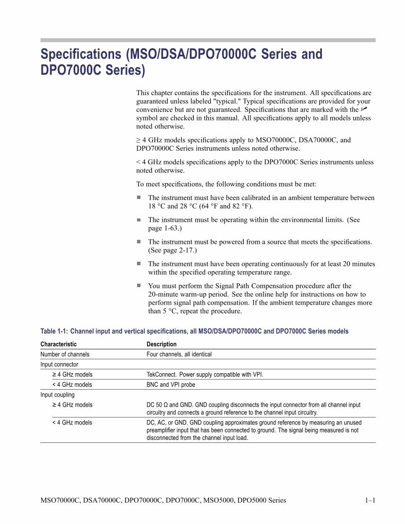
Table 1-1: Channel input and vertical specifications, all MSO/DSA/DPO70000C and DPO7000C Series modelsCharacteristic DescriptionNumber of channels Four channels, all identicalInput connector
≥ 4 GHz models TekConnect. Power supply compatible with VPI.< 4 GHz models BNC and VPI probe
Input coupling≥ 4 GHz models DC 50 Ω and GND. GND coupling disconnects the input connector from all channel input
circuitry and connects a ground reference to the channel input circuitry.< 4 GHz models DC, AC, or GND. GND coupling approximates ground reference by measuring an unused
preamplifier input that has been connected to ground. The signal being measured is notdisconnected from the channel input load.
MSO70000C, DSA70000C, DPO70000C, DPO7000C, MSO5000, DPO5000 Series 1–1
Specifications (MSO/DSA/DPO70000C Series and DPO7000C Series)
Table 1-1: Channel input and vertical specifications, all MSO/DSA/DPO70000C and DPO7000C Series models (cont.)
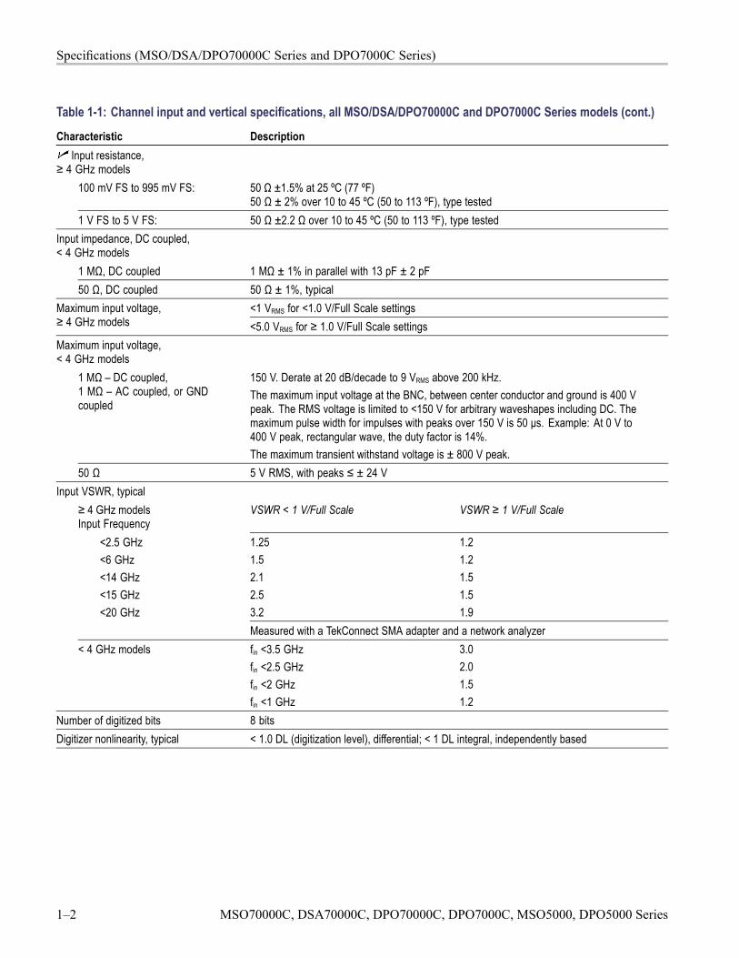
Characteristic DescriptionInput resistance,
≥ 4 GHz models100 mV FS to 995 mV FS: 50 Ω ±1.5% at 25 ºC (77 ºF)
50 Ω ± 2% over 10 to 45 ºC (50 to 113 ºF), type tested1 V FS to 5 V FS: 50 Ω ±2.2 Ω over 10 to 45 ºC (50 to 113 ºF), type tested
Input impedance, DC coupled,< 4 GHz models
1 MΩ, DC coupled 1 MΩ ± 1% in parallel with 13 pF ± 2 pF50 Ω, DC coupled 50 Ω ± 1%, typical
<1 VRMS for <1.0 V/Full Scale settingsMaximum input voltage,≥ 4 GHz models <5.0 VRMS for ≥ 1.0 V/Full Scale settingsMaximum input voltage,< 4 GHz models
1 MΩ – DC coupled,1 MΩ – AC coupled, or GNDcoupled
150 V. Derate at 20 dB/decade to 9 VRMS above 200 kHz.The maximum input voltage at the BNC, between center conductor and ground is 400 Vpeak. The RMS voltage is limited to <150 V for arbitrary waveshapes including DC. Themaximum pulse width for impulses with peaks over 150 V is 50 μs. Example: At 0 V to400 V peak, rectangular wave, the duty factor is 14%.The maximum transient withstand voltage is ± 800 V peak.
50 Ω 5 V RMS, with peaks ≤ ± 24 VInput VSWR, typical
≥ 4 GHz modelsInput Frequency
VSWR < 1 V/Full Scale VSWR ≥ 1 V/Full Scale
1.251.52.12.53.2
1.21.21.51.51.9
<2.5 GHz<6 GHz<14 GHz<15 GHz<20 GHz
Measured with a TekConnect SMA adapter and a network analyzer< 4 GHz models fin <3.5 GHz
fin <2.5 GHzfin <2 GHzfin <1 GHz
3.02.01.51.2
Number of digitized bits 8 bitsDigitizer nonlinearity, typical < 1.0 DL (digitization level), differential; < 1 DL integral, independently based
1–2 MSO70000C, DSA70000C, DPO70000C, DPO7000C, MSO5000, DPO5000 Series
Specifications (MSO/DSA/DPO70000C Series and DPO7000C Series)
Table 1-1: Channel input and vertical specifications, all MSO/DSA/DPO70000C and DPO7000C Series models (cont.)
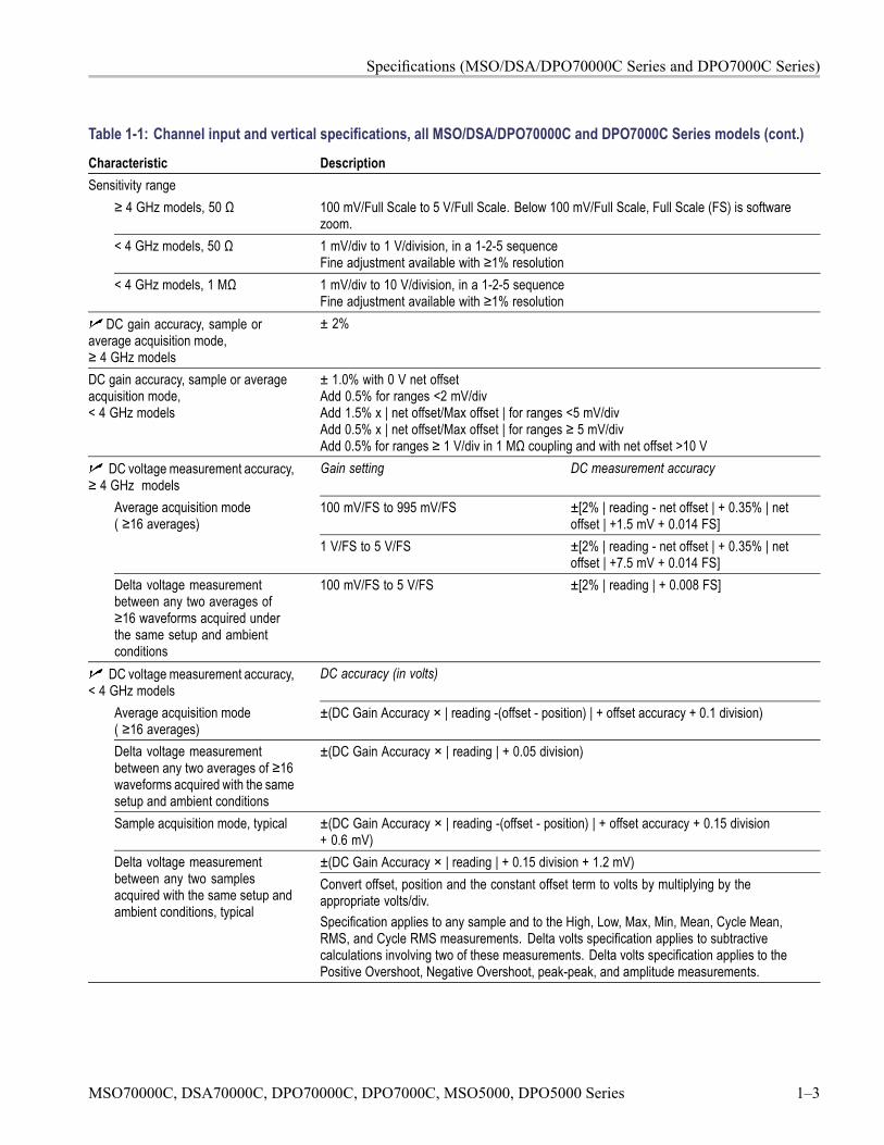
Characteristic DescriptionSensitivity range
≥ 4 GHz models, 50 Ω 100 mV/Full Scale to 5 V/Full Scale. Below 100 mV/Full Scale, Full Scale (FS) is softwarezoom.
< 4 GHz models, 50 Ω 1 mV/div to 1 V/division, in a 1-2-5 sequenceFine adjustment available with ≥1% resolution
< 4 GHz models, 1 MΩ 1 mV/div to 10 V/division, in a 1-2-5 sequenceFine adjustment available with ≥1% resolution
DC gain accuracy, sample oraverage acquisition mode,≥ 4 GHz models
± 2%
DC gain accuracy, sample or averageacquisition mode,< 4 GHz models
± 1.0% with 0 V net offsetAdd 0.5% for ranges <2 mV/divAdd 1.5% x | net offset/Max offset | for ranges <5 mV/divAdd 0.5% x | net offset/Max offset | for ranges ≥ 5 mV/divAdd 0.5% for ranges ≥ 1 V/div in 1 MΩ coupling and with net offset >10 V
DC voltage measurement accuracy,≥ 4 GHz models
Gain setting DC measurement accuracy
100 mV/FS to 995 mV/FS ±[2% | reading - net offset | + 0.35% | netoffset | +1.5 mV + 0.014 FS]
Average acquisition mode( ≥16 averages)
1 V/FS to 5 V/FS ±[2% | reading - net offset | + 0.35% | netoffset | +7.5 mV + 0.014 FS]
Delta voltage measurementbetween any two averages of≥16 waveforms acquired underthe same setup and ambientconditions
100 mV/FS to 5 V/FS ±[2% | reading | + 0.008 FS]
DC voltage measurement accuracy,< 4 GHz models
DC accuracy (in volts)
Average acquisition mode( ≥16 averages)
±(DC Gain Accuracy × | reading -(offset - position) | + offset accuracy + 0.1 division)
Delta voltage measurementbetween any two averages of ≥16waveforms acquired with the samesetup and ambient conditions
±(DC Gain Accuracy × | reading | + 0.05 division)
Sample acquisition mode, typical ±(DC Gain Accuracy × | reading -(offset - position) | + offset accuracy + 0.15 division+ 0.6 mV)±(DC Gain Accuracy × | reading | + 0.15 division + 1.2 mV)Delta voltage measurement
between any two samplesacquired with the same setup andambient conditions, typical
Convert offset, position and the constant offset term to volts by multiplying by theappropriate volts/div.Specification applies to any sample and to the High, Low, Max, Min, Mean, Cycle Mean,RMS, and Cycle RMS measurements. Delta volts specification applies to subtractivecalculations involving two of these measurements. Delta volts specification applies to thePositive Overshoot, Negative Overshoot, peak-peak, and amplitude measurements.
MSO70000C, DSA70000C, DPO70000C, DPO7000C, MSO5000, DPO5000 Series 1–3
Specifications (MSO/DSA/DPO70000C Series and DPO7000C Series)
Table 1-1: Channel input and vertical specifications, all MSO/DSA/DPO70000C and DPO7000C Series models (cont.)
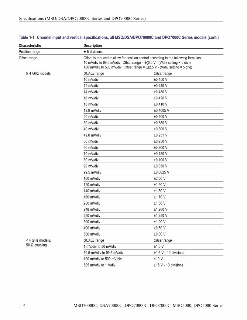
Characteristic DescriptionPosition range ± 5 divisionsOffset range Offset is reduced to allow for position control according to the following formulas:
10 mV/div to 99.5 mV/div: Offset range = ±(0.5 V - (V/div setting × 5 div))100 mV/div to 500 mV/div: Offset range = ±(2.5 V - (V/div setting × 5 div))SCALE range Offset range10 mV/div ±0.450 V12 mV/div ±0.440 V14 mV/div ±0.430 V16 mV/div ±0.420 V18 mV/div ±0.410 V19.9 mV/div ±0.4005 V20 mV/div ±0.400 V30 mV/div ±0.350 V40 mV/div ±0.300 V49.8 mV/div ±0.251 V50 mV/div ±0.250 V60 mV/div ±0.200 V70 mV/div ±0.150 V80 mV/div ±0.100 V90 mV/div ±0.050 V99.5 mV/div ±0.0025 V100 mV/div ±2.00 V120 mV/div ±1.90 V140 mV/div ±1.80 V160 mV/div ±1.70 V200 mV/div ±1.50 V248 mV/div ±1.260 V250 mV/div ±1.250 V300 mV/div ±1.00 V400 mV/div ±0.50 V
≥ 4 GHz models
500 mV/div ±0.00 VSCALE range Offset range1 mV/div to 50 mV/div ±1.0 V50.5 mV/div to 99.5 mV/div ±1.5 V - 10 divisions100 mV/div to 500 mV/div ±10 V
< 4 GHz models,50 Ω coupling
505 mV/div to 1 V/div ±15 V - 10 divisions
1–4 MSO70000C, DSA70000C, DPO70000C, DPO7000C, MSO5000, DPO5000 Series
Specifications (MSO/DSA/DPO70000C Series and DPO7000C Series)
Table 1-1: Channel input and vertical specifications, all MSO/DSA/DPO70000C and DPO7000C Series models (cont.)
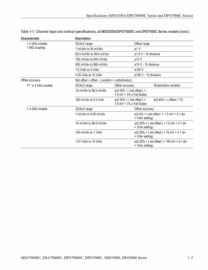
Characteristic DescriptionSCALE range Offset range1 mV/div to 50 mV/div ±1 V50.5 mV/div to 99.5 mV/div ±1.5 V - 10 divisions100 mV/div to 500 mV/div ±10 V505 mV/div to 995 mV/div ±15 V - 10 divisions1.0 V/div to 5 V/div ±100 V
< 4 GHz models,1 MΩ coupling
5.05 V/div to 10 V/div ±150 V - 10 divisionsOffset accuracy Net offset = offset - ( position × volts/division).
SCALE range Offset accuracy Temperature variation10 mV/div to 99.5 mV/div ±(0.35% × | net offset | +
1.5 mV + 1% x Full Scale)
≥ 4 GHz models
100 mV/div to 0.5 V/div ±(0.35% × | net offset | +7.5 mV + 1% x Full Scale)
±(0.45% × | offset | /°C)
SCALE range Offset accuracy1 mV/div to 9.95 mV/div ±(0.2% × | net offset | + 1.5 mV + 0.1 div
× V/div setting)10 mV/div to 99.5 mV/div ±(0.35% × | net offset | + 1.5 mV + 0.1 div
× V/div setting)100 mV/div to 1 V/div ±(0.35% × | net offset | + 15 mV + 0.1 div
× V/div setting)
< 4 GHz models
1.01 V/div to 10 V/div ±(0.25% × | net offset | + 150 mV + 0.1 div× V/div setting)
MSO70000C, DSA70000C, DPO70000C, DPO7000C, MSO5000, DPO5000 Series 1–5
Specifications (MSO/DSA/DPO70000C Series and DPO7000C Series)
Table 1-1: Channel input and vertical specifications, all MSO/DSA/DPO70000C and DPO7000C Series models (cont.)
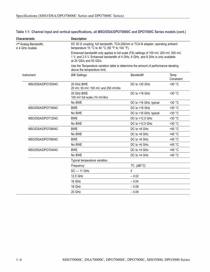
Characteristic DescriptionAnalog Bandwidth,
≥ 4 GHz modelsDC 50 Ω coupling, full bandwidth, TCA-292mm or TCA-N adapter, operating ambienttemperature 15 °C to 40 °C (59 °F to 104 °F).Enhanced bandwidth only applies to full scale (FS) settings of 100 mV, 200 mV, 500 mV,1 V, and 2.5 V. Enhanced bandwidth of 4 GHz, 6 GHz, and 8 GHz is only availableat 25 GS/s and 50 GS/s.Use the Temperature variation table to determine the amount of performance deratingabove the temperature limit.
Instrument BW Settings Bandwidth TempConstraint
20 GHz BWE20 mV, 50 mV, 100 mV, and 250 mV/div
DC to >20 GHz <30 °C
20 GHz BWE100 mV full scale (10 mV/div)
DC to >18 GHz <30 °C
MSO/DSA/DPO72004C
No BWE DC to >16 GHz, typical <30 °CBWE DC to >16 GHz <30 °CMSO/DSA/DPO71604CNo BWE DC to >16 GHz, typical <30 °CBWE DC to >12.5 GHz <30 °CMSO/DSA/DPO71254CNo BWE DC to >12.5 GHz <30 °CBWE DC to >8 GHz <45 °CMSO/DSA/DPO70804CNo BWE DC to >8 GHz <45 °CBWE DC to >6 GHz <45 °CMSO/DSA/DPO70604CNo BWE DC to >6 GHz <45 °CBWE DC to >4 GHz <45 °CMSO/DSA/DPO70404CNo BWE DC to >4 GHz <45 °CTypical temperature variationFrequency TC, (dB/°C)DC — 11 GHz 012.5 GHz – 0.0216 GHz – 0.0418 GHz – 0.0920 GHz – 0.09
1–6 MSO70000C, DSA70000C, DPO70000C, DPO7000C, MSO5000, DPO5000 Series
Specifications (MSO/DSA/DPO70000C Series and DPO7000C Series)
Table 1-1: Channel input and vertical specifications, all MSO/DSA/DPO70000C and DPO7000C Series models (cont.)
Characteristic DescriptionMSO/DSA/DPO72004C,MSO/DSA/DPO71604C
DC >12.5 GHz, typical
MSO/DSA/DPO71254C DC >11 GHz, typicalMSO/DSA/DPO70804C DC >8 GHz, typicalMSO/DSA/DPO70604C DC >6 GHz, typical
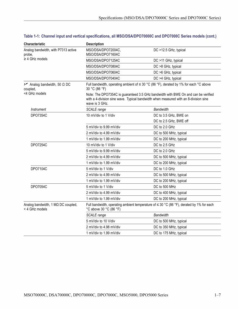
Analog bandwidth, with P7313 activeprobe,≥ 4 GHz models
MSO/DSA/DPO70404C DC >4 GHz, typicalAnalog bandwidth, 50 Ω DC
coupled,<4 GHz models
Full bandwidth, operating ambient of ≤ 30 °C (86 °F), derated by 1% for each °C above30 °C (86 °F)Note: The DPO7354C is guaranteed 3.5 GHz bandwidth with BWE On and can be verifiedwith a 4-division sine wave. Typical bandwidth when measured with an 8-division sinewave is 3 GHz.
Instrument SCALE range Bandwidth10 mV/div to 1 V/div DC to 3.5 GHz, BWE on
DC to 2.5 GHz, BWE off5 mV/div to 9.99 mV/div DC to 2.0 GHz2 mV/div to 4.99 mV/div DC to 500 MHz, typical
DPO7354C
1 mV/div to 1.99 mV/div DC to 200 MHz, typical10 mV/div to 1 V/div DC to 2.5 GHz5 mV/div to 9.99 mV/div DC to 2.0 GHz2 mV/div to 4.99 mV/div DC to 500 MHz, typical
DPO7254C
1 mV/div to 1.99 mV/div DC to 200 MHz, typical5 mV/div to 1 V/div DC to 1.0 GHz2 mV/div to 4.99 mV/div DC to 500 MHz, typical
DPO7104C
1 mV/div to 1.99 mV/div DC to 200 MHz, typical5 mV/div to 1 V/div DC to 500 MHz2 mV/div to 4.99 mV/div DC to 400 MHz, typical
DPO7054C
1 mV/div to 1.99 mV/div DC to 200 MHz, typicalFull bandwidth, operating ambient temperature of ≤ 30 °C (86 °F), derated by 1% for each°C above 30 °C (86 °F)SCALE range Bandwidth5 mV/div to 10 V/div DC to 500 MHz, typical2 mV/div to 4.98 mV/div DC to 350 MHz, typical
Analog bandwidth, 1 MΩ DC coupled,< 4 GHz models
1 mV/div to 1.99 mV/div DC to 175 MHz, typical
MSO70000C, DSA70000C, DPO70000C, DPO7000C, MSO5000, DPO5000 Series 1–7
Specifications (MSO/DSA/DPO70000C Series and DPO7000C Series)
Table 1-1: Channel input and vertical specifications, all MSO/DSA/DPO70000C and DPO7000C Series models (cont.)
Characteristic DescriptionFull bandwidth, operating ambient of ≤ 30 °C (86 °F), derated by 1% for each °C above30 °C (86 °F)SCALE range Bandwidth≥ 100 mV/div DC to 2.5 GHz50 mV/div to 99.5 mV/div DC to 2.0 GHz20 mV/div to 49.8 mV/div DC to 500 MHz
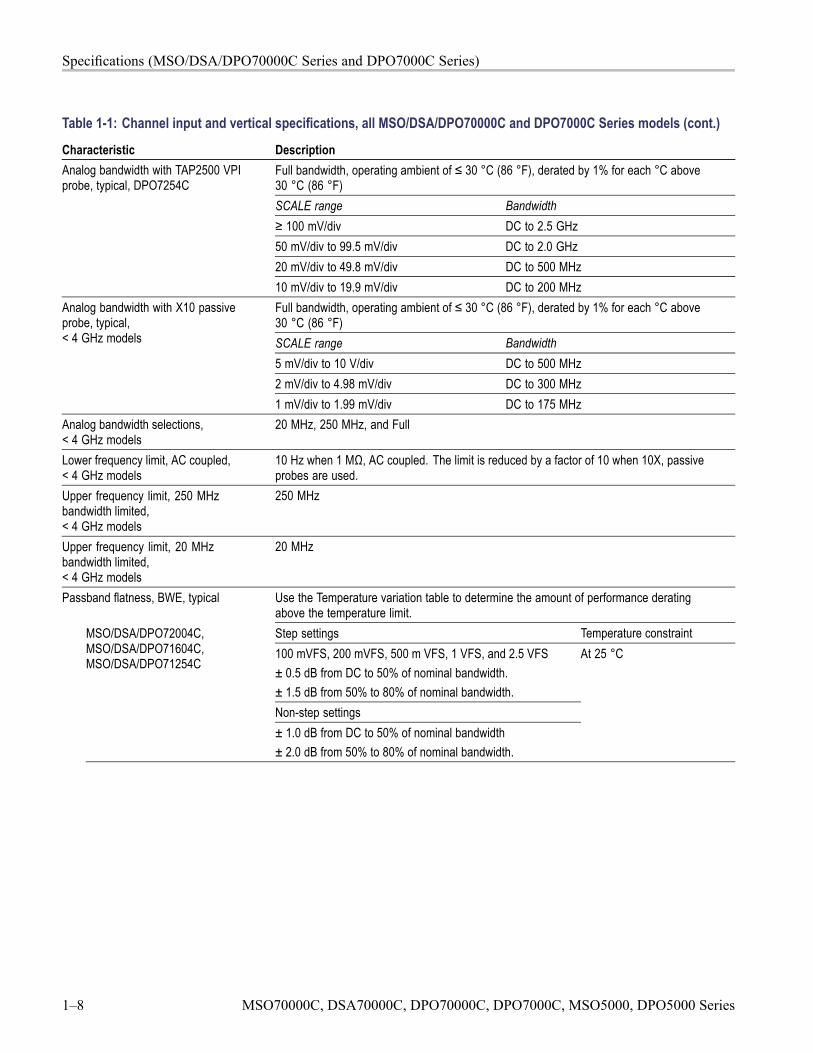
Analog bandwidth with TAP2500 VPIprobe, typical, DPO7254C
10 mV/div to 19.9 mV/div DC to 200 MHzFull bandwidth, operating ambient of ≤ 30 °C (86 °F), derated by 1% for each °C above30 °C (86 °F)SCALE range Bandwidth5 mV/div to 10 V/div DC to 500 MHz2 mV/div to 4.98 mV/div DC to 300 MHz
Analog bandwidth with X10 passiveprobe, typical,< 4 GHz models
1 mV/div to 1.99 mV/div DC to 175 MHzAnalog bandwidth selections,< 4 GHz models
20 MHz, 250 MHz, and Full
Lower frequency limit, AC coupled,< 4 GHz models
10 Hz when 1 MΩ, AC coupled. The limit is reduced by a factor of 10 when 10X, passiveprobes are used.
Upper frequency limit, 250 MHzbandwidth limited,< 4 GHz models
250 MHz
Upper frequency limit, 20 MHzbandwidth limited,< 4 GHz models
20 MHz
Passband flatness, BWE, typical Use the Temperature variation table to determine the amount of performance deratingabove the temperature limit.Step settings Temperature constraint100 mVFS, 200 mVFS, 500 m VFS, 1 VFS, and 2.5 VFS± 0.5 dB from DC to 50% of nominal bandwidth.± 1.5 dB from 50% to 80% of nominal bandwidth.Non-step settings
MSO/DSA/DPO72004C,MSO/DSA/DPO71604C,MSO/DSA/DPO71254C
± 1.0 dB from DC to 50% of nominal bandwidth± 2.0 dB from 50% to 80% of nominal bandwidth.
At 25 °C
1–8 MSO70000C, DSA70000C, DPO70000C, DPO7000C, MSO5000, DPO5000 Series
Specifications (MSO/DSA/DPO70000C Series and DPO7000C Series)
Table 1-1: Channel input and vertical specifications, all MSO/DSA/DPO70000C and DPO7000C Series models (cont.)
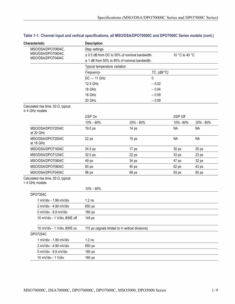
Characteristic DescriptionStep settingsMSO/DSA/DPO70804C,
MSO/DSA/DPO70604C,MSO/DSA/DPO70404C
± 0.5 dB from DC to 50% of nominal bandwidth.± 1 dB from 50% to 80% of nominal bandwidth.
10 °C to 40 °C
Typical temperature variationFrequency TC, (dB/°C)DC — 11 GHz12.5 GHz16 GHz18 GHz20 GHz
0– 0.02– 0.04– 0.09– 0.09
Calculated rise time, 50 Ω, typical≥ 4 GHz models
DSP On DSP Off10% - 90% 20% - 80% 10% - 90% 20% - 80%
MSO/DSA/DPO72004Cat 20 GHz
19.0 ps 14 ps NA NA
MSO/DSA/DPO72004Cat 18 GHz
22 ps 15 ps NA NA
MSO/DSA/DPO71604C 24.5 ps 17 ps 30 ps 20 psMSO/DSA/DPO71254C 32.0 ps 22 ps 33 ps 23 psMSO/DSA/DPO70804C 49 ps 34 ps 47 ps 32 psMSO/DSA/DPO70604C 65 ps 45 ps 62 ps 43 psMSO/DSA/DPO70404C 98 ps 68 ps 93 ps 65 ps
Calculated rise time, 50 Ω, typical< 4 GHz models
10% - 90%DPO7354C
1 mV/div - 1.99 mV/div 1.2 ns2 mV/div - 4.99 mV/div 650 ps5 mV/div - 9.9 mV/div 180 ps10 mV/div - 1 V/div, BWE off 145 ps
10 mV/div - 1 V/div, BWE on 115 ps (signals limited to 4 vertical divisions)DPO7254C
1 mV/div - 1.99 mV/div 1.2 ns2 mV/div - 4.99 mV/div 650 ps5 mV/div - 9.9 mV/div 180 ps10 mV/div - 1 V/div 160 ps
MSO70000C, DSA70000C, DPO70000C, DPO7000C, MSO5000, DPO5000 Series 1–9
Specifications (MSO/DSA/DPO70000C Series and DPO7000C Series)
Table 1-1: Channel input and vertical specifications, all MSO/DSA/DPO70000C and DPO7000C Series models (cont.)
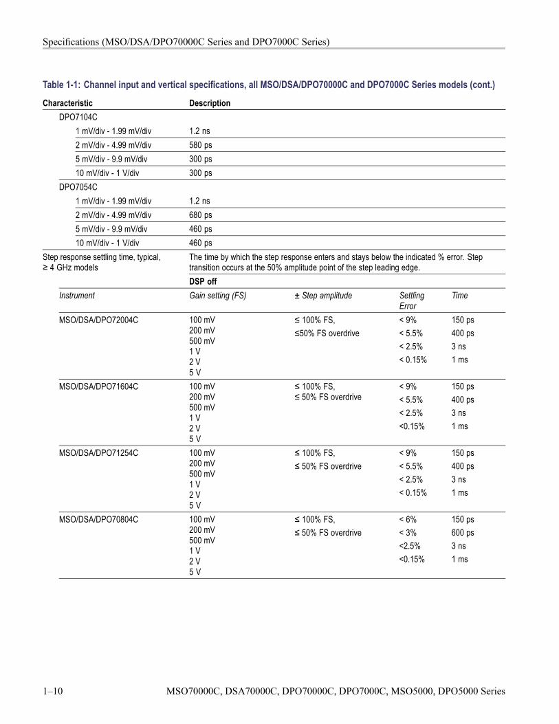
Characteristic DescriptionDPO7104C
1 mV/div - 1.99 mV/div 1.2 ns2 mV/div - 4.99 mV/div 580 ps5 mV/div - 9.9 mV/div 300 ps10 mV/div - 1 V/div 300 ps
DPO7054C1 mV/div - 1.99 mV/div 1.2 ns2 mV/div - 4.99 mV/div 680 ps5 mV/div - 9.9 mV/div 460 ps10 mV/div - 1 V/div 460 ps
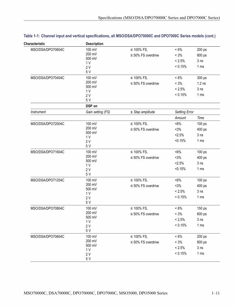
Step response settling time, typical,≥ 4 GHz models
The time by which the step response enters and stays below the indicated % error. Steptransition occurs at the 50% amplitude point of the step leading edge.DSP off
Instrument Gain setting (FS) ± Step amplitude SettlingError
Time
MSO/DSA/DPO72004C 100 mV200 mV500 mV1 V2 V5 V
≤ 100% FS,≤50% FS overdrive
< 9%< 5.5%< 2.5%< 0.15%
150 ps400 ps3 ns1 ms
MSO/DSA/DPO71604C 100 mV200 mV500 mV1 V2 V5 V
≤ 100% FS,≤ 50% FS overdrive
< 9%< 5.5%< 2.5%<0.15%
150 ps400 ps3 ns1 ms
MSO/DSA/DPO71254C 100 mV200 mV500 mV1 V2 V5 V
≤ 100% FS,≤ 50% FS overdrive
< 9%< 5.5%< 2.5%< 0.15%
150 ps400 ps3 ns1 ms
MSO/DSA/DPO70804C 100 mV200 mV500 mV1 V2 V5 V
≤ 100% FS,≤ 50% FS overdrive
< 6%< 3%<2.5%<0.15%
150 ps600 ps3 ns1 ms
1–10 MSO70000C, DSA70000C, DPO70000C, DPO7000C, MSO5000, DPO5000 Series
Specifications (MSO/DSA/DPO70000C Series and DPO7000C Series)
Table 1-1: Channel input and vertical specifications, all MSO/DSA/DPO70000C and DPO7000C Series models (cont.)
Characteristic DescriptionMSO/DSA/DPO70604C 100 mV
200 mV500 mV1 V2 V5 V
≤ 100% FS,≤ 50% FS overdrive
< 6%< 3%< 2.5%< 0.15%
200 ps800 ps3 ns1 ms
MSO/DSA/DPO70404C 100 mV200 mV500 mV1 V2 V5 V
≤ 100% FS,≤ 50% FS overdrive
< 6%< 3%< 2.5%< 0.15%
300 ps1.2 ns3 ns1 ms
DSP onInstrument Gain setting (FS) ± Step amplitude Settling Error
Amount TimeMSO/DSA/DPO72004C 100 mV
200 mV500 mV1 V2 V5 V
≤ 100% FS,≤ 50% FS overdrive
<6%<3%<2.5%<0.15%
100 ps400 ps3 ns1 ms
MSO/DSA/DPO71604C 100 mV200 mV500 mV1 V2 V5 V
≤ 100% FS,≤ 50% FS overdrive
<6%<3%<2.5%<0.15%
100 ps400 ps3 ns1 ms
MSO/DSA/DPO71254C 100 mV200 mV500 mV1 V2 V5 V
≤ 100% FS,≤ 50% FS overdrive
<6%<3%< 2.5%< 0.15%
100 ps400 ps3 ns1 ms
MSO/DSA/DPO70804C 100 mV200 mV500 mV1 V2 V5 V
≤ 100% FS,≤ 50% FS overdrive
< 6%< 3%< 2.5%< 0.15%
150 ps600 ps3 ns1 ms
MSO/DSA/DPO70604C 100 mV200 mV500 mV1 V2 V5 V
≤ 100% FS,≤ 50% FS overdrive
< 6%< 3%< 2.5%< 0.15%
200 ps800 ps3 ns1 ms
MSO70000C, DSA70000C, DPO70000C, DPO7000C, MSO5000, DPO5000 Series 1–11
Specifications (MSO/DSA/DPO70000C Series and DPO7000C Series)
Table 1-1: Channel input and vertical specifications, all MSO/DSA/DPO70000C and DPO7000C Series models (cont.)
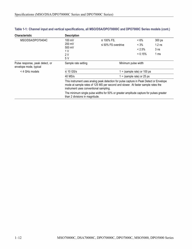
Characteristic DescriptionMSO/DSA/DPO70404C 100 mV
200 mV500 mV1 V2 V5 V
≤ 100% FS,≤ 50% FS overdrive
< 6%< 3%< 2.5%< 0.15%
300 ps1.2 ns3 ns1 ms
Pulse response, peak detect, orenvelope mode, typical
Sample rate setting Minimum pulse width
≤ 10 GS/s 1 ÷ (sample rate) or 100 ps40 MS/s 1 ÷ (sample rate) or 25 ps
< 4 GHz models
This instrument uses analog peak detection for pulse capture in Peak Detect or Envelopemode at sample rates of 125 MS per second and slower. At faster sample rates theinstrument uses conventional sampling.The minimum single pulse widths for 50% or greater amplitude capture for pulses greaterthan 2 divisions in magnitude.
1–12 MSO70000C, DSA70000C, DPO70000C, DPO7000C, MSO5000, DPO5000 Series
Specifications (MSO/DSA/DPO70000C Series and DPO7000C Series)
Table 1-1: Channel input and vertical specifications, all MSO/DSA/DPO70000C and DPO7000C Series models (cont.)
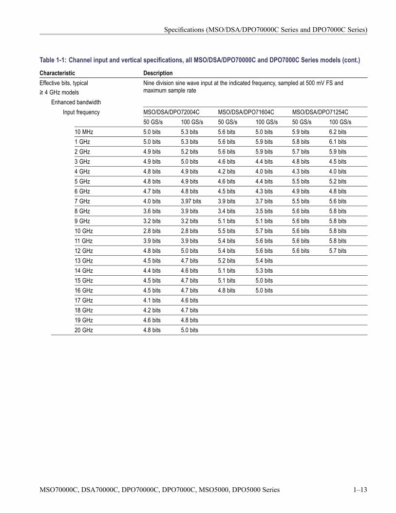
Characteristic DescriptionEffective bits, typical≥ 4 GHz models
Nine division sine wave input at the indicated frequency, sampled at 500 mV FS andmaximum sample rate
Enhanced bandwidthInput frequency MSO/DSA/DPO72004C MSO/DSA/DPO71604C MSO/DSA/DPO71254C
50 GS/s 100 GS/s 50 GS/s 100 GS/s 50 GS/s 100 GS/s10 MHz 5.0 bits 5.3 bits 5.6 bits 5.0 bits 5.9 bits 6.2 bits1 GHz 5.0 bits 5.3 bits 5.6 bits 5.9 bits 5.8 bits 6.1 bits2 GHz 4.9 bits 5.2 bits 5.6 bits 5.9 bits 5.7 bits 5.9 bits3 GHz 4.9 bits 5.0 bits 4.6 bits 4.4 bits 4.8 bits 4.5 bits4 GHz 4.8 bits 4.9 bits 4.2 bits 4.0 bits 4.3 bits 4.0 bits5 GHz 4.8 bits 4.9 bits 4.6 bits 4.4 bits 5.5 bits 5.2 bits6 GHz 4.7 bits 4.8 bits 4.5 bits 4.3 bits 4.9 bits 4.8 bits7 GHz 4.0 bits 3.97 bits 3.9 bits 3.7 bits 5.5 bits 5.6 bits8 GHz 3.6 bits 3.9 bits 3.4 bits 3.5 bits 5.6 bits 5.8 bits9 GHz 3.2 bits 3.2 bits 5.1 bits 5.1 bits 5.6 bits 5.8 bits10 GHz 2.8 bits 2.8 bits 5.5 bits 5.7 bits 5.6 bits 5.8 bits11 GHz 3.9 bits 3.9 bits 5.4 bits 5.6 bits 5.6 bits 5.8 bits12 GHz 4.8 bits 5.0 bits 5.4 bits 5.6 bits 5.6 bits 5.7 bits13 GHz 4.5 bits 4.7 bits 5.2 bits 5.4 bits14 GHz 4.4 bits 4.6 bits 5.1 bits 5.3 bits15 GHz 4.5 bits 4.7 bits 5.1 bits 5.0 bits16 GHz 4.5 bits 4.7 bits 4.8 bits 5.0 bits17 GHz 4.1 bits 4.6 bits18 GHz 4.2 bits 4.7 bits19 GHz 4.6 bits 4.8 bits20 GHz 4.8 bits 5.0 bits
MSO70000C, DSA70000C, DPO70000C, DPO7000C, MSO5000, DPO5000 Series 1–13
Specifications (MSO/DSA/DPO70000C Series and DPO7000C Series)
Table 1-1: Channel input and vertical specifications, all MSO/DSA/DPO70000C and DPO7000C Series models (cont.)
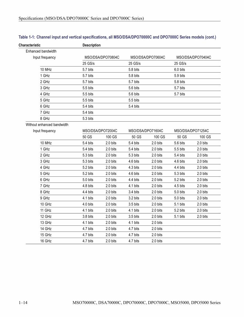
Characteristic DescriptionEnhanced bandwidth
Input frequency MSO/DSA/DPO70804C MSO/DSA/DPO70604C MSO/DSA/DPO70404C25 GS/s 25 GS/s 25 GS/s
10 MHz 5.7 bits 5.8 bits 6.0 bits1 GHz 5.7 bits 5.8 bits 5.9 bits2 GHz 5.7 bits 5.7 bits 5.8 bits3 GHz 5.5 bits 5.6 bits 5.7 bits4 GHz 5.5 bits 5.6 bits 5.7 bits5 GHz 5.5 bits 5.5 bits6 GHz 5.4 bits 5.4 bits7 GHz 5.4 bits8 GHz 5.3 bits
Without enhanced bandwidthInput frequency MSO/DSA/DPO72004C MSO/DSA/DPO71604C MSO/DSA/DPO71254C
50 GS 100 GS 50 GS 100 GS 50 GS 100 GS10 MHz 5.4 bits 2.0 bits 5.4 bits 2.0 bits 5.6 bits 2.0 bits1 GHz 5.4 bits 2.0 bits 5.4 bits 2.0 bits 5.5 bits 2.0 bits2 GHz 5.3 bits 2.0 bits 5.3 bits 2.0 bits 5.4 bits 2.0 bits3 GHz 5.3 bits 2.0 bits 4.6 bits 2.0 bits 4.6 bits 2.0 bits4 GHz 5.2 bits 2.0 bits 4.3 bits 2.0 bits 4.4 bits 2.0 bits5 GHz 5.2 bits 2.0 bits 4.6 bits 2.0 bits 5.3 bits 2.0 bits6 GHz 5.0 bits 2.0 bits 4.4 bits 2.0 bits 5.2 bits 2.0 bits7 GHz 4.8 bits 2.0 bits 4.1 bits 2.0 bits 4.5 bits 2.0 bits8 GHz 4.4 bits 2.0 bits 3.4 bits 2.0 bits 5.0 bits 2.0 bits9 GHz 4.1 bits 2.0 bits 3.2 bits 2.0 bits 5.0 bits 2.0 bits10 GHz 4.0 bits 2.0 bits 3.5 bits 2.0 bits 5.1 bits 2.0 bits11 GHz 4.1 bits 2.0 bits 4.1 bits 2.0 bits 5.2 bits 2.0 bits12 GHz 3.8 bits 2.0 bits 3.5 bits 2.0 bits 5.1 bits 2.0 bits13 GHz 4.1 bits 2.0 bits 4.1 bits 2.0 bits14 GHz 4.7 bits 2.0 bits 4.7 bits 2.0 bits15 GHz 4.7 bits 2.0 bits 4.7 bits 2.0 bits16 GHz 4.7 bits 2.0 bits 4.7 bits 2.0 bits
1–14 MSO70000C, DSA70000C, DPO70000C, DPO7000C, MSO5000, DPO5000 Series
Specifications (MSO/DSA/DPO70000C Series and DPO7000C Series)
Table 1-1: Channel input and vertical specifications, all MSO/DSA/DPO70000C and DPO7000C Series models (cont.)
Characteristic DescriptionWithout enhanced bandwidth
Input frequency MSO/DS/DPO70804C MSO/DSA/DPO70604C MSO/DSA/DPO70404C25 GS/s 25 GS/s 25 GS/s
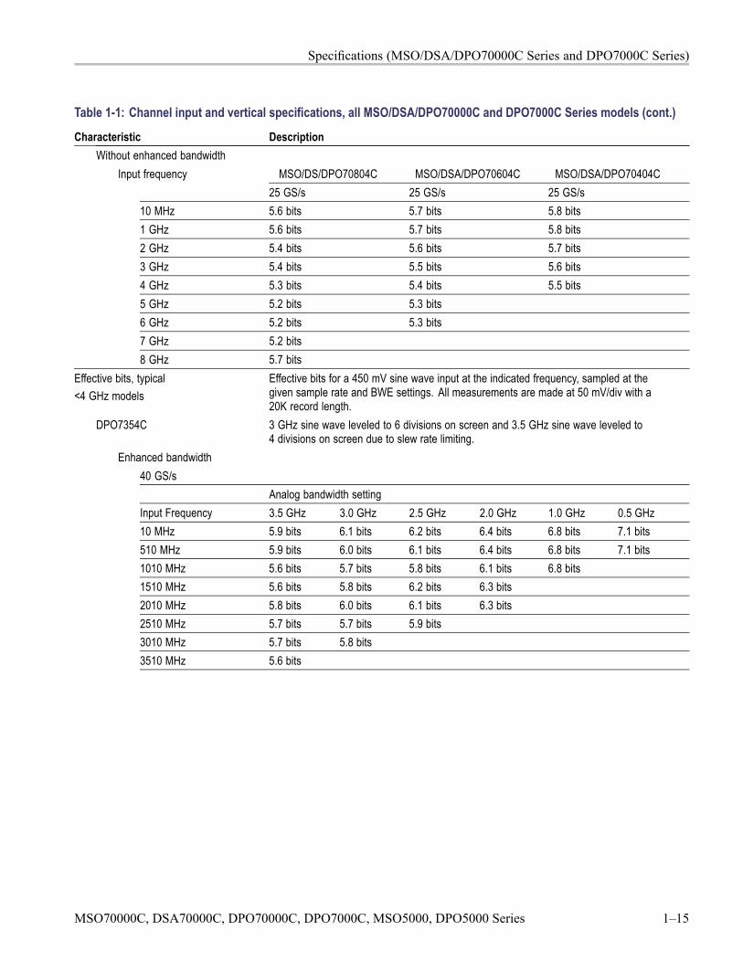
10 MHz 5.6 bits 5.7 bits 5.8 bits1 GHz 5.6 bits 5.7 bits 5.8 bits2 GHz 5.4 bits 5.6 bits 5.7 bits3 GHz 5.4 bits 5.5 bits 5.6 bits4 GHz 5.3 bits 5.4 bits 5.5 bits5 GHz 5.2 bits 5.3 bits6 GHz 5.2 bits 5.3 bits7 GHz 5.2 bits8 GHz 5.7 bits
Effective bits, typical<4 GHz models
Effective bits for a 450 mV sine wave input at the indicated frequency, sampled at thegiven sample rate and BWE settings. All measurements are made at 50 mV/div with a20K record length.
DPO7354C 3 GHz sine wave leveled to 6 divisions on screen and 3.5 GHz sine wave leveled to4 divisions on screen due to slew rate limiting.
Enhanced bandwidth40 GS/s
Analog bandwidth settingInput Frequency 3.5 GHz 3.0 GHz 2.5 GHz 2.0 GHz 1.0 GHz 0.5 GHz10 MHz 5.9 bits 6.1 bits 6.2 bits 6.4 bits 6.8 bits 7.1 bits510 MHz 5.9 bits 6.0 bits 6.1 bits 6.4 bits 6.8 bits 7.1 bits1010 MHz 5.6 bits 5.7 bits 5.8 bits 6.1 bits 6.8 bits1510 MHz 5.6 bits 5.8 bits 6.2 bits 6.3 bits2010 MHz 5.8 bits 6.0 bits 6.1 bits 6.3 bits2510 MHz 5.7 bits 5.7 bits 5.9 bits3010 MHz 5.7 bits 5.8 bits3510 MHz 5.6 bits
MSO70000C, DSA70000C, DPO70000C, DPO7000C, MSO5000, DPO5000 Series 1–15
Specifications (MSO/DSA/DPO70000C Series and DPO7000C Series)
Table 1-1: Channel input and vertical specifications, all MSO/DSA/DPO70000C and DPO7000C Series models (cont.)
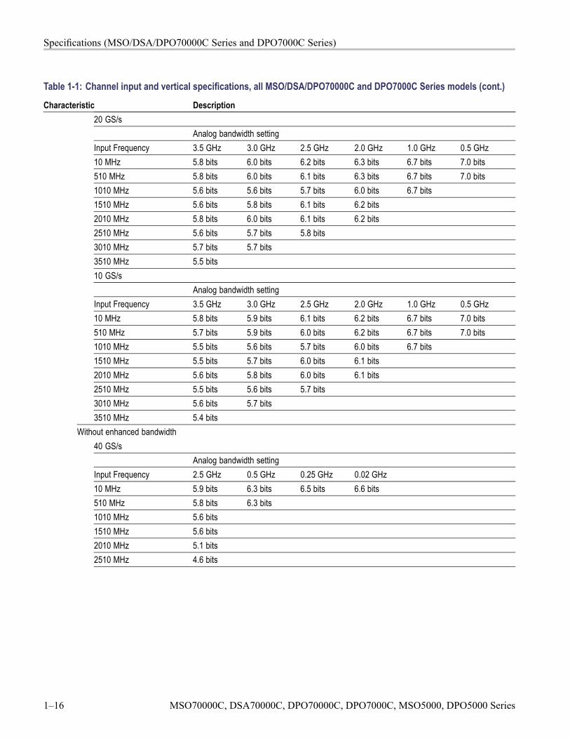
Characteristic Description20 GS/s
Analog bandwidth settingInput Frequency 3.5 GHz 3.0 GHz 2.5 GHz 2.0 GHz 1.0 GHz 0.5 GHz10 MHz 5.8 bits 6.0 bits 6.2 bits 6.3 bits 6.7 bits 7.0 bits510 MHz 5.8 bits 6.0 bits 6.1 bits 6.3 bits 6.7 bits 7.0 bits1010 MHz 5.6 bits 5.6 bits 5.7 bits 6.0 bits 6.7 bits1510 MHz 5.6 bits 5.8 bits 6.1 bits 6.2 bits2010 MHz 5.8 bits 6.0 bits 6.1 bits 6.2 bits2510 MHz 5.6 bits 5.7 bits 5.8 bits3010 MHz 5.7 bits 5.7 bits3510 MHz 5.5 bits10 GS/s
Analog bandwidth settingInput Frequency 3.5 GHz 3.0 GHz 2.5 GHz 2.0 GHz 1.0 GHz 0.5 GHz10 MHz 5.8 bits 5.9 bits 6.1 bits 6.2 bits 6.7 bits 7.0 bits510 MHz 5.7 bits 5.9 bits 6.0 bits 6.2 bits 6.7 bits 7.0 bits1010 MHz 5.5 bits 5.6 bits 5.7 bits 6.0 bits 6.7 bits1510 MHz 5.5 bits 5.7 bits 6.0 bits 6.1 bits2010 MHz 5.6 bits 5.8 bits 6.0 bits 6.1 bits2510 MHz 5.5 bits 5.6 bits 5.7 bits3010 MHz 5.6 bits 5.7 bits3510 MHz 5.4 bits
Without enhanced bandwidth40 GS/s
Analog bandwidth settingInput Frequency 2.5 GHz 0.5 GHz 0.25 GHz 0.02 GHz10 MHz 5.9 bits 6.3 bits 6.5 bits 6.6 bits510 MHz 5.8 bits 6.3 bits1010 MHz 5.6 bits1510 MHz 5.6 bits2010 MHz 5.1 bits2510 MHz 4.6 bits
1–16 MSO70000C, DSA70000C, DPO70000C, DPO7000C, MSO5000, DPO5000 Series
Specifications (MSO/DSA/DPO70000C Series and DPO7000C Series)
Table 1-1: Channel input and vertical specifications, all MSO/DSA/DPO70000C and DPO7000C Series models (cont.)
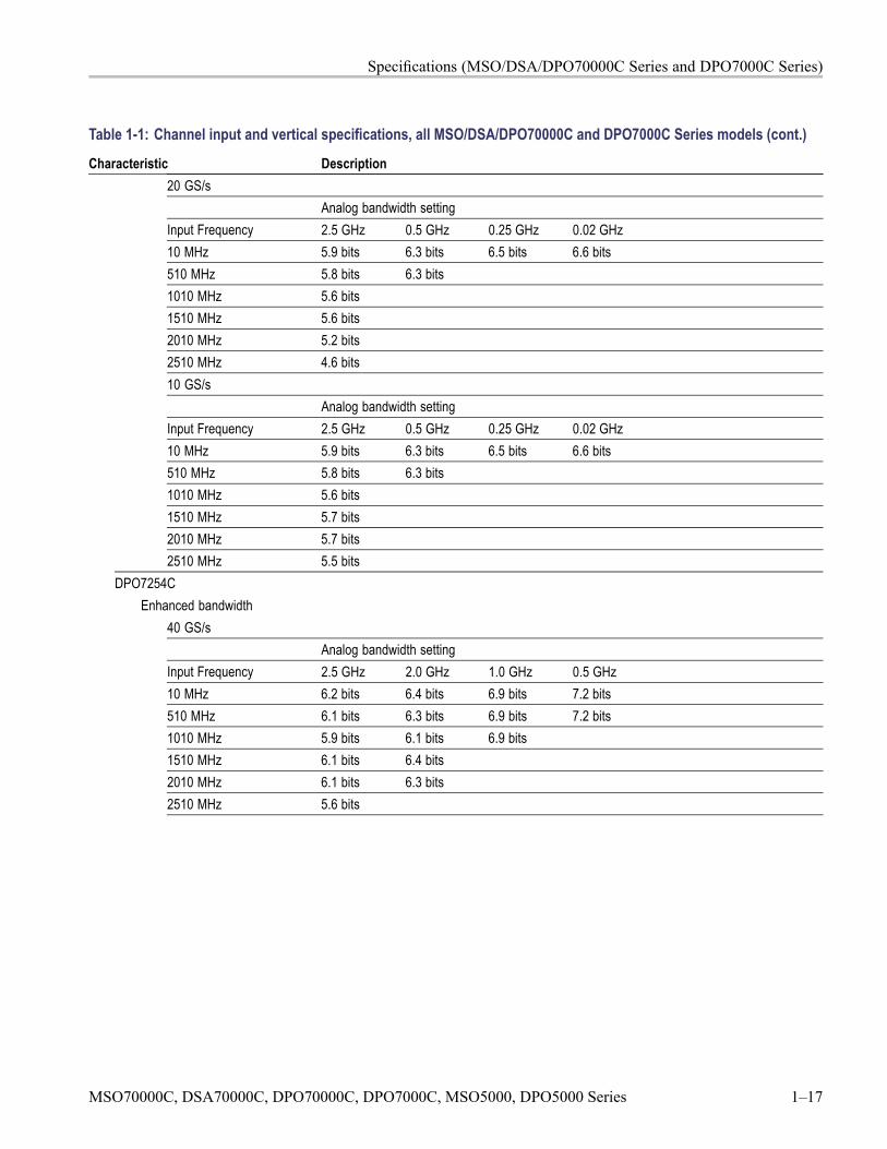
Characteristic Description20 GS/s
Analog bandwidth settingInput Frequency 2.5 GHz 0.5 GHz 0.25 GHz 0.02 GHz10 MHz 5.9 bits 6.3 bits 6.5 bits 6.6 bits510 MHz 5.8 bits 6.3 bits1010 MHz 5.6 bits1510 MHz 5.6 bits2010 MHz 5.2 bits2510 MHz 4.6 bits10 GS/s
Analog bandwidth settingInput Frequency 2.5 GHz 0.5 GHz 0.25 GHz 0.02 GHz10 MHz 5.9 bits 6.3 bits 6.5 bits 6.6 bits510 MHz 5.8 bits 6.3 bits1010 MHz 5.6 bits1510 MHz 5.7 bits2010 MHz 5.7 bits2510 MHz 5.5 bits
DPO7254CEnhanced bandwidth
40 GS/sAnalog bandwidth setting
Input Frequency 2.5 GHz 2.0 GHz 1.0 GHz 0.5 GHz10 MHz 6.2 bits 6.4 bits 6.9 bits 7.2 bits510 MHz 6.1 bits 6.3 bits 6.9 bits 7.2 bits1010 MHz 5.9 bits 6.1 bits 6.9 bits1510 MHz 6.1 bits 6.4 bits2010 MHz 6.1 bits 6.3 bits2510 MHz 5.6 bits
MSO70000C, DSA70000C, DPO70000C, DPO7000C, MSO5000, DPO5000 Series 1–17
Specifications (MSO/DSA/DPO70000C Series and DPO7000C Series)
Table 1-1: Channel input and vertical specifications, all MSO/DSA/DPO70000C and DPO7000C Series models (cont.)
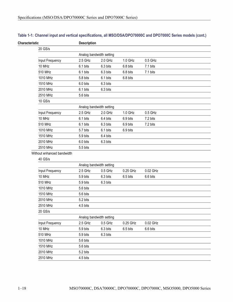
Characteristic Description20 GS/s
Analog bandwidth settingInput Frequency 2.5 GHz 2.0 GHz 1.0 GHz 0.5 GHz10 MHz 6.1 bits 6.3 bits 6.8 bits 7.1 bits510 MHz 6.1 bits 6.3 bits 6.8 bits 7.1 bits1010 MHz 5.8 bits 6.1 bits 6.8 bits1510 MHz 6.0 bits 6.3 bits2010 MHz 6.1 bits 6.3 bits2510 MHz 5.6 bits10 GS/s
Analog bandwidth settingInput Frequency 2.5 GHz 2.0 GHz 1.0 GHz 0.5 GHz10 MHz 6.1 bits 6.4 bits 6.9 bits 7.2 bits510 MHz 6.1 bits 6.3 bits 6.9 bits 7.2 bits1010 MHz 5.7 bits 6.1 bits 6.9 bits1510 MHz 5.9 bits 6.4 bits2010 MHz 6.0 bits 6.3 bits2510 MHz 5.5 bits
Without enhanced bandwidth40 GS/s
Analog bandwidth settingInput Frequency 2.5 GHz 0.5 GHz 0.25 GHz 0.02 GHz10 MHz 5.9 bits 6.3 bits 6.5 bits 6.6 bits510 MHz 5.9 bits 6.3 bits1010 MHz 5.6 bits1510 MHz 5.6 bits2010 MHz 5.2 bits2510 MHz 4.5 bits20 GS/s
Analog bandwidth settingInput Frequency 2.5 GHz 0.5 GHz 0.25 GHz 0.02 GHz10 MHz 5.9 bits 6.3 bits 6.5 bits 6.6 bits510 MHz 5.9 bits 6.3 bits1010 MHz 5.6 bits1510 MHz 5.6 bits2010 MHz 5.2 bits2510 MHz 4.5 bits
1–18 MSO70000C, DSA70000C, DPO70000C, DPO7000C, MSO5000, DPO5000 Series
Specifications (MSO/DSA/DPO70000C Series and DPO7000C Series)
Table 1-1: Channel input and vertical specifications, all MSO/DSA/DPO70000C and DPO7000C Series models (cont.)
Characteristic Description10 GS/s
Analog bandwidth settingInput Frequency 2.5 GHz 0.5 GHz 0.25 GHz 0.02 GHz10 MHz 5.9 bits 6.3 bits 6.5 bits 6.6 bits510 MHz 5.9 bits 6.3 bits1010 MHz 5.6 bits1510 MHz 5.7 bits2010 MHz 5.8 bits2510 MHz 5.5 bits
DPO7104CEnhanced bandwidth
20 GS/sAnalog bandwidth setting
Input Frequency 1.0 GHz 0.5 GHz10 MHz 6.7 bits 7.2 bits510 MHz 6.7 bits 7.2 bits1010 MHz 6.7 bits10 GS/s
Analog bandwidth settingInput Frequency 1.0 GHz 0.5 GHz10 MHz 6.6 bits 7.1 bits510 MHz 6.5 bits 7.1 bits1010 MHz 6.5 bits5 GS/s
Analog bandwidth settingInput Frequency 1.0 GHz 0.5 GHz10 MHz 6.4 bits 7.0 bits510 MHz 6.4 bits 7.0 bits1010 MHz 6.3 bits
Without enhanced bandwidth20 GS/s
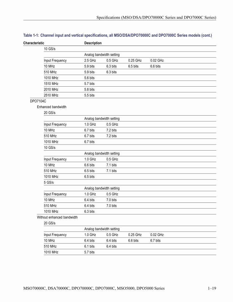
Analog bandwidth settingInput Frequency 1.0 GHz 0.5 GHz 0.25 GHz 0.02 GHz10 MHz 6.4 bits 6.4 bits 6.6 bits 6.7 bits510 MHz 6.1 bits 6.4 bits1010 MHz 5.7 bits
MSO70000C, DSA70000C, DPO70000C, DPO7000C, MSO5000, DPO5000 Series 1–19
Specifications (MSO/DSA/DPO70000C Series and DPO7000C Series)
Table 1-1: Channel input and vertical specifications, all MSO/DSA/DPO70000C and DPO7000C Series models (cont.)
Characteristic Description10 GS/s
Analog bandwidth settingInput Frequency 1.0 GHz 0.5 GHz 0.25 GHz 0.02 GHz10 MHz 6.4 bits 6.4 bits 6.6 bits 6.7 bits510 MHz 6.3 bits 6.4 bits1010 MHz 6.3 bits5 GS/s
Analog bandwidth settingInput Frequency 1.0 GHz 0.5 GHz 0.25 GHz 0.02 GHz10 MHz 6.4 bits 6.4 bits 6.6 bits 6.7 bits510 MHz 6.3 bits 6.4 bits1010 MHz 6.3 bits
DPO7054CEnhanced bandwidth
10 GS/sAnalog bandwidth setting
Input Frequency 0.5 GHz10 MHz 6.8 bits510 MHz 6.8 bits5 GS/s
Analog bandwidth settingInput Frequency 0.5 GHz10 MHz 6.7 bits510 MHz 6.7 bits2.5 GS/s
Analog bandwidth settingInput Frequency 0.5 GHz10 MHz 6.5 bits510 MHz 6.4 bits
Without enhanced bandwidth10 GS/s
Analog bandwidth settingInput Frequency 0.5 GHz 0.25 GHz 0.02 GHz10 MHz 6.5 bits 6.6 bits 6.7 bits510 MHz 6.4 bits
1–20 MSO70000C, DSA70000C, DPO70000C, DPO7000C, MSO5000, DPO5000 Series
Specifications (MSO/DSA/DPO70000C Series and DPO7000C Series)
Table 1-1: Channel input and vertical specifications, all MSO/DSA/DPO70000C and DPO7000C Series models (cont.)
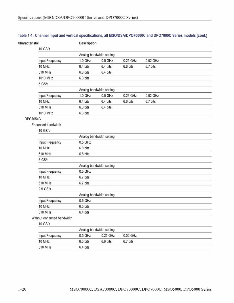
Characteristic Description5 GS/s
Analog bandwidth settingInput Frequency 0.5 GHz 0.25 GHz 0.02 GHz10 MHz 6.5 bits 6.6 bits 6.7 bits510 MHz 6.4 bits2.5 GS/s
Analog bandwidth settingInput Frequency 0.5 GHz 0.25 GHz 0.02 GHz10 MHz 6.5 bits 6.6 bits 6.7 bits510 MHz 6.4 bits
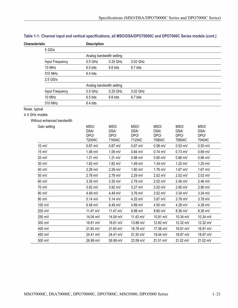
Noise, typical≥ 4 GHz models
Without enhanced bandwidthGain setting MSO/
DSA/DPO/72004C
MSO/DSA/DPO/71604C
MSO/DSA/DPO/71254C
MSO/DSA/DPO/70804C
MSO/DSA/DPO/70604C
MSO/DSA/DPO/70404C
10 mV 0.87 mV 0.87 mV 0.67 mV 0.58 mV 0.53 mV 0.50 mV15 mV 1.06 mV 1.06 mV 0.84 mV 0.74 mV 0.73 mV 0.69 mV20 mV 1.21 mV 1.21 mV 0.98 mV 0.90 mV 0.86 mV 0.86 mV30 mV 1.82 mV 1.82 mV 1.49 mV 1.34 mV 1.25 mV 1.25 mV40 mV 2.29 mV 2.29 mV 1.80 mV 1.76 mV 1.67 mV 1.67 mV50 mV 2.78 mV 2.78 mV 2.29 mV 2.02 mV 2.02 mV 2.02 mV60 mV 3.35 mV 3.35 mV 2.78 mV 2.52 mV 2.46 mV 2.46 mV70 mV 3.92 mV 3.92 mV 3.27 mV 3.02 mV 2.90 mV 2.90 mV80 mV 4.49 mV 4.49 mV 3.76 mV 3.52 mV 3.34 mV 3.34 mV90 mV 5.14 mV 5.14 mV 4.25 mV 3.87 mV 3.78 mV 3.78 mV100 mV 6.48 mV 6.48 mV 4.89 mV 4.50 mV 4.28 mV 4.28 mV200 mV 11.47 mV 11.47 mV 8.98 mV 8.80 mV 8.36 mV 8.36 mV250 mV 14.04 mV 14.04 mV 11.43 mV 10.81 mV 10.34 mV 10.34 mV300 mV 16.61 mV 16.61 mV 13.88 mV 12.82 mV 12.32 mV 12.32 mV400 mV 21.83 mV 21.83 mV 18.78 mV 17.36 mV 16.91 mV 16.91 mV450 mV 24.41 mV 24.41 mV 21.30 mV 19.44 mV 18.97 mV 18.97 mV500 mV 26.99 mV 26.99 mV 23.59 mV 21.51 mV 21.02 mV 21.02 mV
MSO70000C, DSA70000C, DPO70000C, DPO7000C, MSO5000, DPO5000 Series 1–21
Specifications (MSO/DSA/DPO70000C Series and DPO7000C Series)
Table 1-1: Channel input and vertical specifications, all MSO/DSA/DPO70000C and DPO7000C Series models (cont.)
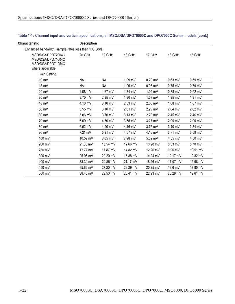
Characteristic DescriptionEnhanced bandwidth, sample rates less than 100 GS/s.
MSO/DSA/DPO72004CMSO/DSA/DPO71604CMSO/DSA/DPO71254Cwhere applicable
20 GHz 19 GHz 18 GHz 17 GHz 16 GHz 15 GHz
Gain Setting10 mV NA NA 1.09 mV 0.70 mV 0.63 mV 0.59 mV15 mV NA NA 1.06 mV 0.93 mV 0.75 mV 0.79 mV20 mV 2.08 mV 1.67 mV 1.34 mV 1.09 mV 0.88 mV 0.92 mV30 mV 3.70 mV 2.35 mV 1.90 mV 1.57 mV 1.35 mV 1.31 mV40 mV 4.18 mV 3.10 mV 2.53 mV 2.08 mV 1.68 mV 1.67 mV50 mV 3.55 mV 3.10 mV 2.61 mV 2.29 mV 2.04 mV 2.02 mV60 mV 5.06 mV 3.70 mV 3.13 mV 2.78 mV 2.45 mV 2.46 mV70 mV 6.09 mV 4.30 mV 3.65 mV 3.27 mV 2.99 mV 2.90 mV80 mV 6.62 mV 4.90 mV 4.16 mV 3.76 mV 3.40 mV 3.34 mV90 mV 7.21 mV 5.31 mV 4.57 mV 4.16 mV 3.71 mV 3.59 mV100 mV 10.52 mV 8.35 mV 7.98 mV 5.32 mV 4.55 mV 4.50 mV200 mV 21.38 mV 15.54 mV 12.66 mV 10.28 mV 8.33 mV 8.70 mV250 mV 17.77 mV 17.87 mV 14.82 mV 12.26 mV 9.96 mV 10.51 mV300 mV 25.05 mV 20.20 mV 16.88 mV 14.24 mV 12.17 mV 12.32 mV400 mV 33.34 mV 24.86 mV 21.17 mV 18.26 mV 17.07 mV 15.98 mV450 mV 35.86 mV 27.20 mV 23.29 mV 20.25 mV 18.6 mV 17.80 mV500 mV 38.40 mV 29.53 mV 25.41 mV 22.23 mV 20.29 mV 19.61 mV
1–22 MSO70000C, DSA70000C, DPO70000C, DPO7000C, MSO5000, DPO5000 Series
Specifications (MSO/DSA/DPO70000C Series and DPO7000C Series)
Table 1-1: Channel input and vertical specifications, all MSO/DSA/DPO70000C and DPO7000C Series models (cont.)
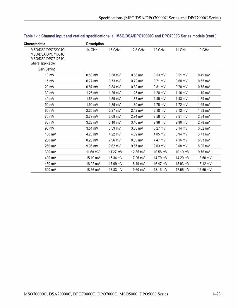
Characteristic DescriptionMSO/DSA/DPO72004CMSO/DSA/DPO71604CMSO/DSA/DPO71254Cwhere applicable
14 GHz 13 GHz 12.5 GHz 12 GHz 11 GHz 10 GHz
Gain Setting10 mV 0.58 mV 0.58 mV 0.55 mV 0.53 mV 0.51 mV 0.49 mV15 mV 0.77 mV 0.73 mV 0.72 mV 0.71 mV 0.68 mV 0.65 mV20 mV 0.87 mV 0.84 mV 0.82 mV 0.81 mV 0.78 mV 0.75 mV30 mV 1.28 mV 1.26 mV 1.28 mV 1.20 mV 1.16 mV 1.10 mV40 mV 1.63 mV 1.59 mV 1.67 mV 1.49 mV 1.43 mV 1.39 mV50 mV 1.92 mV 1.85 mV 1.80 mV 1.78 mV 1.72 mV 1.65 mV60 mV 2.35 mV 2.27 mV 2.42 mV 2.18 mV 2.12 mV 1.99 mV70 mV 2.79 mV 2.69 mV 2.94 mV 2.58 mV 2.51 mV 2.34 mV80 mV 3.23 mV 3.10 mV 3.40 mV 2.98 mV 2.90 mV 2.78 mV90 mV 3.51 mV 3.39 mV 3.63 mV 3.27 mV 3.14 mV 3.02 mV100 mV 4.26 mV 4.22 mV 4.09 mV 4.05 mV 3.94 mV 3.73 mV200 mV 8.23 mV 7.96 mV 8.39 mV 7.47 mV 7.16 mV 6.93 mV250 mV 9.95 mV 9.62 mV 9.57 mV 9.03 mV 8.68 mV 8.35 mV300 mV 11.68 mV 11.27 mV 12.35 mV 10.58 mV 10.19 mV 9.76 mV400 mV 15.19 mV 15.34 mV 17.26 mV 14.79 mV 14.29 mV 13.60 mV450 mV 16.92 mV 17.09 mV 18.49 mV 16.47 mV 15.93 mV 15.12 mV500 mV 18.66 mV 18.83 mV 19.60 mV 18.15 mV 17.56 mV 16.65 mV
MSO70000C, DSA70000C, DPO70000C, DPO7000C, MSO5000, DPO5000 Series 1–23
Specifications (MSO/DSA/DPO70000C Series and DPO7000C Series)
Table 1-1: Channel input and vertical specifications, all MSO/DSA/DPO70000C and DPO7000C Series models (cont.)
Characteristic DescriptionMSO/DSA/DPO72004CMSO/DSA/DPO71604CMSO/DSA/DPO71254Cwhere applicable
9 GHz 8 GHz 7 GHz 6 GHz 5 GHz 4 GHz
Gain Setting10 mV 0.46 mV 0.45 mV 0.43 mV 0.40 mV 0.37 mV 0.34 mV15 mV 0.63 mV 0.60 mV 0.57 mV 0.54 mV 0.51 mV 0.48 mV20 mV 0.71 mV 0.67 mV 0.63 mV 0.60 mV 0.57 mV 0.53 mV30 mV 1.03 mV 0.99 mV 0.95 mV 0.89 mV 0.84 mV 0.77 mV40 mV 1.33 mV 1.27 mV 1.18 mV 1.10 mV 1.06 mV 0.98 mV50 mV 1.57 mV 1.48 mV 1.41 mV 1.31 mV 1.22 mV 1.10 mV60 mV 1.89 mV 1.79 mV 1.71 mV 1.60 mV 1.49 mV 1.35 mV70 mV 2.21 mV 2.11 mV 2.01 mV 1.88 mV 1.76 mV 1.59 mV80 mV 2.61 mV 2.49 mV 2.37 mV 2.25 mV 2.08 mV 1.96 mV90 mV 2.86 mV 2.74 mV 2.61 mV 2.45 mV 2.29 mV 2.08 mV100 mV 3.55 mV 3.36 mV 3.18 mV 2.99 mV 2.77 mV 2.65 mV200 mV 6.55 mV 6.33 mV 5.94 mV 5.51 mV 5.28 mV 4.90 mV250 mV 7.92 mV 7.63 mV 7.20 mV 6.68 mV 6.34 mV 5.83 mV300 mV 9.30 mV 8.93 mV 8.46 mV 7.84 mV 7.40 mV 6.77 mV400 mV 13.01 mV 12.40 mV 11.81 mV 11.07 mV 10.37 mV 9.51 mV450 mV 14.50 mV 13.80 mV 13.17 mV 12.34 mV 11.53 mV 10.54 mV500 mV 15.98 mV 15.20 mV 14.53 mV 13.61 mV 12.68 mV 11.57 mV
1–24 MSO70000C, DSA70000C, DPO70000C, DPO7000C, MSO5000, DPO5000 Series
Specifications (MSO/DSA/DPO70000C Series and DPO7000C Series)
Table 1-1: Channel input and vertical specifications, all MSO/DSA/DPO70000C and DPO7000C Series models (cont.)
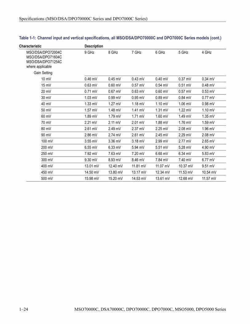
Characteristic DescriptionMSO/DSA/DPO72004CMSO/DSA/DPO71604CMSO/DSA/DPO71254Cwhere applicable
3 GHz 2 GHz 1 GHz 500 MHz
Gain setting10 mV 0.31 mV 0.26 mV 0.20 mV 0.17 mV15 mV 0.44 mV 0.39 mV 0.34 mV 0.27 mV20 mV 0.48 mV 0.44 mV 0.37 mV 0.31 mV30 mV 0.69 mV 0.61 mV 0.52 mV 0.44 mV40 mV 0.88 mV 0.78 mV 0.66 mV 0.57 mV50 mV 1.03 mV 0.91 mV 0.76 mV 0.68 mV60 mV 1.24 mV 1.09 mV 0.91 mV 0.82 mV70 mV 1.45 mV 1.27 mV 1.06 mV 0.95 mV80 mV 1.76 mV 1.51 mV 1.22 mV 1.10 mV90 mV 1.88 mV 1.63 mV 1.35 mV 1.22 mV100 mV 2.38 mV 2.02 mV 1.57 mV 1.31 mV200 mV 4.43 mV 4.12 mV 3.42 mV 2.88 mV250 mV 5.33 mV 4.87 mV 4.07 mV 3.49 mV300 mV 6.22 mV 5.63 mV 4.72 mV 4.10 mV400 mV 8.83 mV 7.86 mV 6.63 mV 5.86 mV450 mV 9.81 mV 8.68 mV 7.34 mV 6.53 mV500 mV 10.80 mV 9.51 mV 8.06 mV 7.20 mV
MSO70000C, DSA70000C, DPO70000C, DPO7000C, MSO5000, DPO5000 Series 1–25
Specifications (MSO/DSA/DPO70000C Series and DPO7000C Series)
Table 1-1: Channel input and vertical specifications, all MSO/DSA/DPO70000C and DPO7000C Series models (cont.)
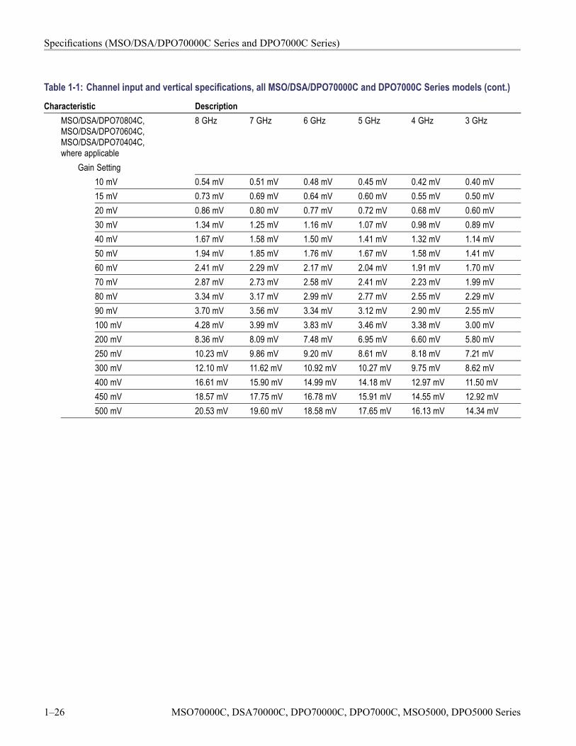
Characteristic DescriptionMSO/DSA/DPO70804C,MSO/DSA/DPO70604C,MSO/DSA/DPO70404C,where applicable
8 GHz 7 GHz 6 GHz 5 GHz 4 GHz 3 GHz
Gain Setting10 mV 0.54 mV 0.51 mV 0.48 mV 0.45 mV 0.42 mV 0.40 mV15 mV 0.73 mV 0.69 mV 0.64 mV 0.60 mV 0.55 mV 0.50 mV20 mV 0.86 mV 0.80 mV 0.77 mV 0.72 mV 0.68 mV 0.60 mV30 mV 1.34 mV 1.25 mV 1.16 mV 1.07 mV 0.98 mV 0.89 mV40 mV 1.67 mV 1.58 mV 1.50 mV 1.41 mV 1.32 mV 1.14 mV50 mV 1.94 mV 1.85 mV 1.76 mV 1.67 mV 1.58 mV 1.41 mV60 mV 2.41 mV 2.29 mV 2.17 mV 2.04 mV 1.91 mV 1.70 mV70 mV 2.87 mV 2.73 mV 2.58 mV 2.41 mV 2.23 mV 1.99 mV80 mV 3.34 mV 3.17 mV 2.99 mV 2.77 mV 2.55 mV 2.29 mV90 mV 3.70 mV 3.56 mV 3.34 mV 3.12 mV 2.90 mV 2.55 mV100 mV 4.28 mV 3.99 mV 3.83 mV 3.46 mV 3.38 mV 3.00 mV200 mV 8.36 mV 8.09 mV 7.48 mV 6.95 mV 6.60 mV 5.80 mV250 mV 10.23 mV 9.86 mV 9.20 mV 8.61 mV 8.18 mV 7.21 mV300 mV 12.10 mV 11.62 mV 10.92 mV 10.27 mV 9.75 mV 8.62 mV400 mV 16.61 mV 15.90 mV 14.99 mV 14.18 mV 12.97 mV 11.50 mV450 mV 18.57 mV 17.75 mV 16.78 mV 15.91 mV 14.55 mV 12.92 mV500 mV 20.53 mV 19.60 mV 18.58 mV 17.65 mV 16.13 mV 14.34 mV
1–26 MSO70000C, DSA70000C, DPO70000C, DPO7000C, MSO5000, DPO5000 Series
Specifications (MSO/DSA/DPO70000C Series and DPO7000C Series)
Table 1-1: Channel input and vertical specifications, all MSO/DSA/DPO70000C and DPO7000C Series models (cont.)
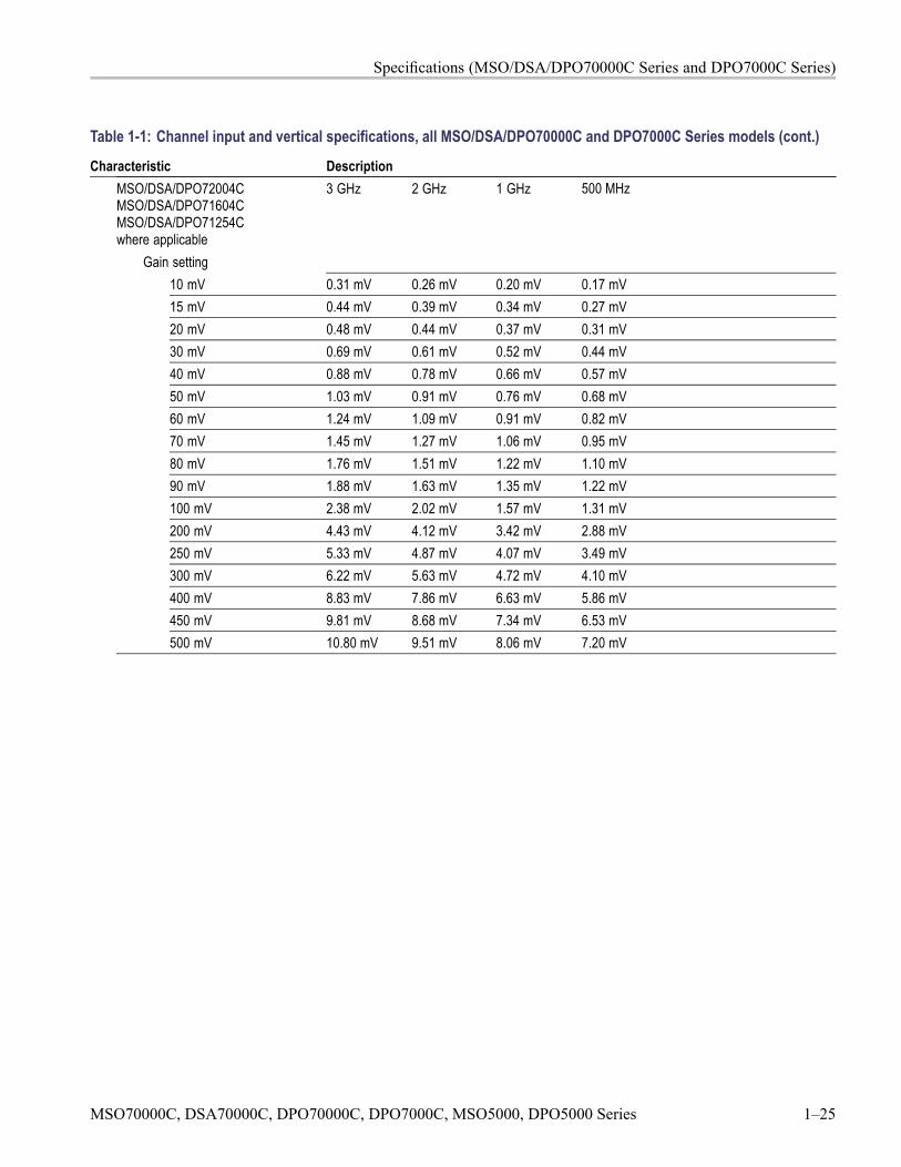
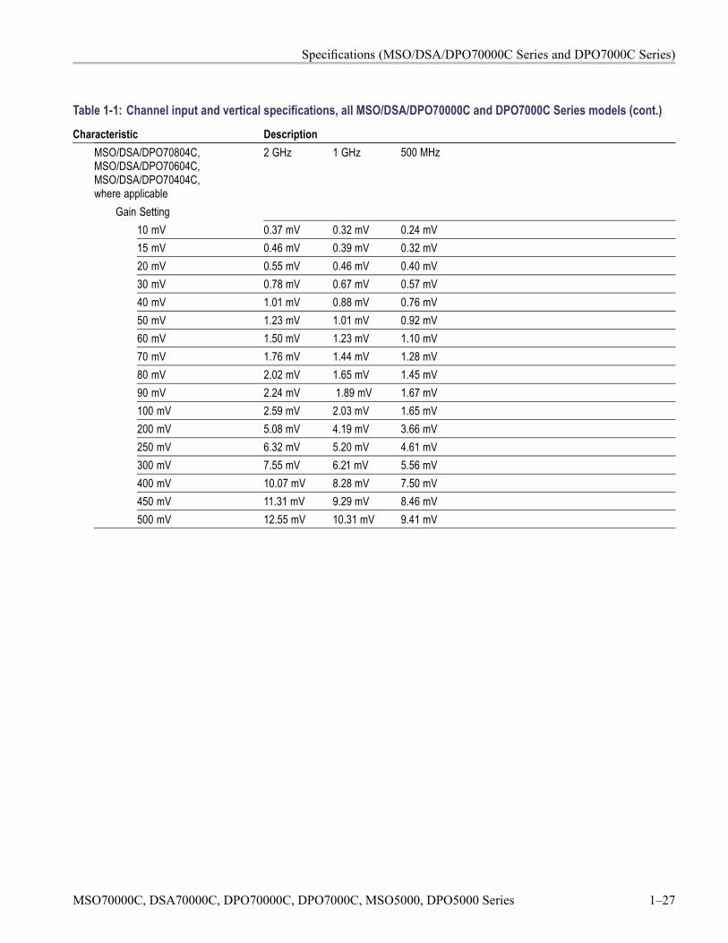
Characteristic DescriptionMSO/DSA/DPO70804C,MSO/DSA/DPO70604C,MSO/DSA/DPO70404C,where applicable
2 GHz 1 GHz 500 MHz
Gain Setting10 mV 0.37 mV 0.32 mV 0.24 mV15 mV 0.46 mV 0.39 mV 0.32 mV20 mV 0.55 mV 0.46 mV 0.40 mV30 mV 0.78 mV 0.67 mV 0.57 mV40 mV 1.01 mV 0.88 mV 0.76 mV50 mV 1.23 mV 1.01 mV 0.92 mV60 mV 1.50 mV 1.23 mV 1.10 mV70 mV 1.76 mV 1.44 mV 1.28 mV80 mV 2.02 mV 1.65 mV 1.45 mV90 mV 2.24 mV 1.89 mV 1.67 mV100 mV 2.59 mV 2.03 mV 1.65 mV200 mV 5.08 mV 4.19 mV 3.66 mV250 mV 6.32 mV 5.20 mV 4.61 mV300 mV 7.55 mV 6.21 mV 5.56 mV400 mV 10.07 mV 8.28 mV 7.50 mV450 mV 11.31 mV 9.29 mV 8.46 mV500 mV 12.55 mV 10.31 mV 9.41 mV
MSO70000C, DSA70000C, DPO70000C, DPO7000C, MSO5000, DPO5000 Series 1–27
Specifications (MSO/DSA/DPO70000C Series and DPO7000C Series)
Table 1-1: Channel input and vertical specifications, all MSO/DSA/DPO70000C and DPO7000C Series models (cont.)
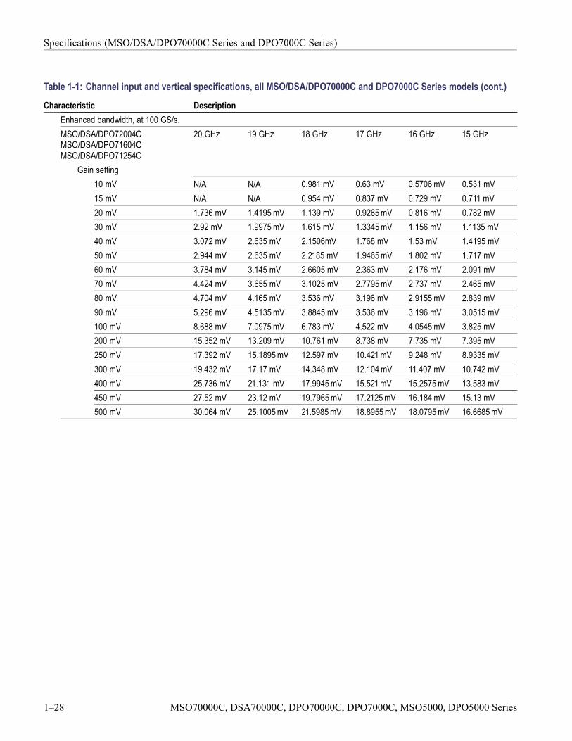
Characteristic DescriptionEnhanced bandwidth, at 100 GS/s.MSO/DSA/DPO72004CMSO/DSA/DPO71604CMSO/DSA/DPO71254C
20 GHz 19 GHz 18 GHz 17 GHz 16 GHz 15 GHz
Gain setting10 mV N/A N/A 0.981 mV 0.63 mV 0.5706 mV 0.531 mV15 mV N/A N/A 0.954 mV 0.837 mV 0.729 mV 0.711 mV20 mV 1.736 mV 1.4195 mV 1.139 mV 0.9265 mV 0.816 mV 0.782 mV30 mV 2.92 mV 1.9975 mV 1.615 mV 1.3345 mV 1.156 mV 1.1135 mV40 mV 3.072 mV 2.635 mV 2.1506mV 1.768 mV 1.53 mV 1.4195 mV50 mV 2.944 mV 2.635 mV 2.2185 mV 1.9465 mV 1.802 mV 1.717 mV60 mV 3.784 mV 3.145 mV 2.6605 mV 2.363 mV 2.176 mV 2.091 mV70 mV 4.424 mV 3.655 mV 3.1025 mV 2.7795 mV 2.737 mV 2.465 mV80 mV 4.704 mV 4.165 mV 3.536 mV 3.196 mV 2.9155 mV 2.839 mV90 mV 5.296 mV 4.5135 mV 3.8845 mV 3.536 mV 3.196 mV 3.0515 mV100 mV 8.688 mV 7.0975 mV 6.783 mV 4.522 mV 4.0545 mV 3.825 mV200 mV 15.352 mV 13.209 mV 10.761 mV 8.738 mV 7.735 mV 7.395 mV250 mV 17.392 mV 15.1895 mV 12.597 mV 10.421 mV 9.248 mV 8.9335 mV300 mV 19.432 mV 17.17 mV 14.348 mV 12.104 mV 11.407 mV 10.742 mV400 mV 25.736 mV 21.131 mV 17.9945 mV 15.521 mV 15.2575 mV 13.583 mV450 mV 27.52 mV 23.12 mV 19.7965 mV 17.2125 mV 16.184 mV 15.13 mV500 mV 30.064 mV 25.1005 mV 21.5985 mV 18.8955 mV 18.0795 mV 16.6685 mV
1–28 MSO70000C, DSA70000C, DPO70000C, DPO7000C, MSO5000, DPO5000 Series
Specifications (MSO/DSA/DPO70000C Series and DPO7000C Series)
Table 1-1: Channel input and vertical specifications, all MSO/DSA/DPO70000C and DPO7000C Series models (cont.)
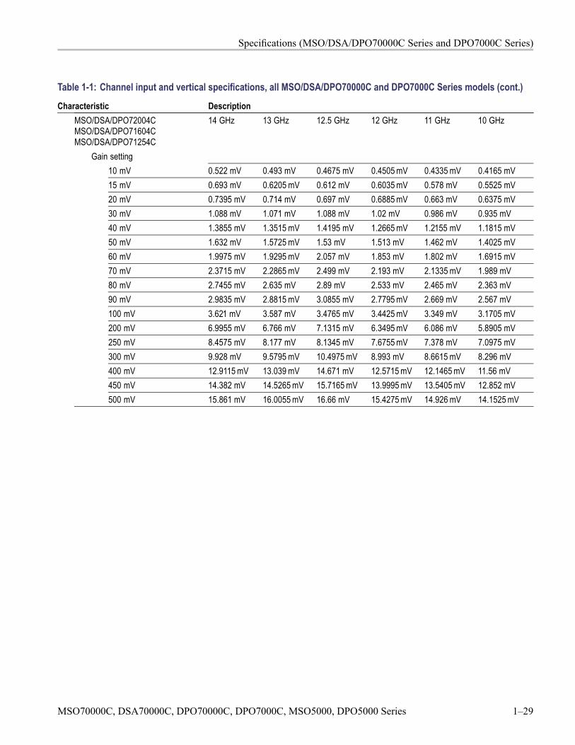
Characteristic DescriptionMSO/DSA/DPO72004CMSO/DSA/DPO71604CMSO/DSA/DPO71254C
14 GHz 13 GHz 12.5 GHz 12 GHz 11 GHz 10 GHz
Gain setting10 mV 0.522 mV 0.493 mV 0.4675 mV 0.4505 mV 0.4335 mV 0.4165 mV15 mV 0.693 mV 0.6205 mV 0.612 mV 0.6035 mV 0.578 mV 0.5525 mV20 mV 0.7395 mV 0.714 mV 0.697 mV 0.6885 mV 0.663 mV 0.6375 mV30 mV 1.088 mV 1.071 mV 1.088 mV 1.02 mV 0.986 mV 0.935 mV40 mV 1.3855 mV 1.3515 mV 1.4195 mV 1.2665 mV 1.2155 mV 1.1815 mV50 mV 1.632 mV 1.5725 mV 1.53 mV 1.513 mV 1.462 mV 1.4025 mV60 mV 1.9975 mV 1.9295 mV 2.057 mV 1.853 mV 1.802 mV 1.6915 mV70 mV 2.3715 mV 2.2865 mV 2.499 mV 2.193 mV 2.1335 mV 1.989 mV80 mV 2.7455 mV 2.635 mV 2.89 mV 2.533 mV 2.465 mV 2.363 mV90 mV 2.9835 mV 2.8815 mV 3.0855 mV 2.7795 mV 2.669 mV 2.567 mV100 mV 3.621 mV 3.587 mV 3.4765 mV 3.4425 mV 3.349 mV 3.1705 mV200 mV 6.9955 mV 6.766 mV 7.1315 mV 6.3495 mV 6.086 mV 5.8905 mV250 mV 8.4575 mV 8.177 mV 8.1345 mV 7.6755 mV 7.378 mV 7.0975 mV300 mV 9.928 mV 9.5795 mV 10.4975 mV 8.993 mV 8.6615 mV 8.296 mV400 mV 12.9115 mV 13.039 mV 14.671 mV 12.5715 mV 12.1465 mV 11.56 mV450 mV 14.382 mV 14.5265 mV 15.7165 mV 13.9995 mV 13.5405 mV 12.852 mV500 mV 15.861 mV 16.0055 mV 16.66 mV 15.4275 mV 14.926 mV 14.1525 mV
MSO70000C, DSA70000C, DPO70000C, DPO7000C, MSO5000, DPO5000 Series 1–29

Specifications (MSO/DSA/DPO70000C Series and DPO7000C Series)
Table 1-1: Channel input and vertical specifications, all MSO/DSA/DPO70000C and DPO7000C Series models (cont.)
Characteristic DescriptionMSO/DSA/DPO72004CMSO/DSA/DPO71604CMSO/DSA/DPO71254C
9 GHz 8 GHz 7 GHz 6 GHz 5 GHz 4 GHz
Gain setting10 mV 0.391 mV 0.3825 mV 0.387 mV 0.36 mV 0.333 mV 0.306 mV15 mV 0.5355 mV 0.51 mV 0.513 mV 0.486 mV 0.459 mV 0.432 mV20 mV 0.6035 mV 0.5695 mV 0.5355 mV 0.51 mV 0.4845 mV 0.4505 mV30 mV 0.8755 mV 0.8415 mV 0.8075 mV 0.7565 mV 0.714 mV 0.6545 mV40 mV 1.1305 mV 1.0795 mV 1.003 mV 0.935 mV 0.901 mV 0.833 mV50 mV 1.3345 mV 1.258 mV 1.1985 mV 1.1135 mV 1.037 mV 0.935 mV60 mV 1.6065 mV 1.5215 mV 1.4535 mV 1.36 mV 1.2665 mV 1.1475 mV70 mV 1.8785 mV 1.7935 mV 1.7085 mV 1.598 mV 1.496 mV 1.3515 mV80 mV 2.2185 mV 2.1165 mV 2.0145 mV 1.9125 mV 1.768 mV 1.666 mV90 mV 2.431 mV 2.329 mV 2.2185 mV 2.0825 mV 1.9465 mV 1.768 mV100 mV 3.0175 mV 2.856 mV 2.703 mV 2.5415 mV 2.3545 mV 2.2525 mV200 mV 5.5675 mV 5.3805 mV 5.049 mV 4.6835 mV 4.488 mV 4.165 mV250 mV 6.732 mV 6.4855 mV 6.12 mV 5.678 mV 5.389 mV 4.9555 mV300 mV 7.905 mV 7.5905 mV 7.191 mV 6.664 mV 6.29 mV 5.7545 mV400 mV 11.0585 mV 10.54 mV 10.0385 mV 9.4095 mV 8.8145 mV 8.0835 mV450 mV 12.325 mV 11.73 mV 11.1945 mV 10.489 mV 9.8005 mV 8.959 mV500 mV 13.583 mV 12.92 mV 12.3505 mV 11.5685 mV 10.778 mV 9.8345 mV
1–30 MSO70000C, DSA70000C, DPO70000C, DPO7000C, MSO5000, DPO5000 Series
Specifications (MSO/DSA/DPO70000C Series and DPO7000C Series)
Table 1-1: Channel input and vertical specifications, all MSO/DSA/DPO70000C and DPO7000C Series models (cont.)
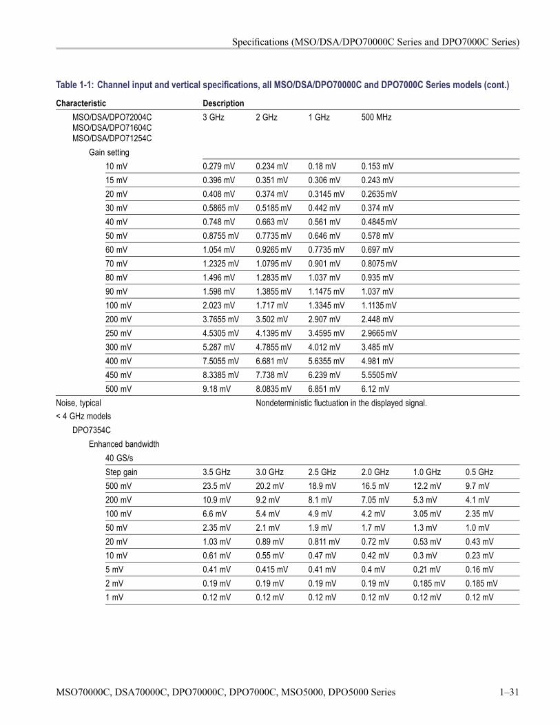
Characteristic DescriptionMSO/DSA/DPO72004CMSO/DSA/DPO71604CMSO/DSA/DPO71254C
3 GHz 2 GHz 1 GHz 500 MHz
Gain setting10 mV 0.279 mV 0.234 mV 0.18 mV 0.153 mV15 mV 0.396 mV 0.351 mV 0.306 mV 0.243 mV20 mV 0.408 mV 0.374 mV 0.3145 mV 0.2635 mV30 mV 0.5865 mV 0.5185 mV 0.442 mV 0.374 mV40 mV 0.748 mV 0.663 mV 0.561 mV 0.4845 mV50 mV 0.8755 mV 0.7735 mV 0.646 mV 0.578 mV60 mV 1.054 mV 0.9265 mV 0.7735 mV 0.697 mV70 mV 1.2325 mV 1.0795 mV 0.901 mV 0.8075 mV80 mV 1.496 mV 1.2835 mV 1.037 mV 0.935 mV90 mV 1.598 mV 1.3855 mV 1.1475 mV 1.037 mV100 mV 2.023 mV 1.717 mV 1.3345 mV 1.1135 mV200 mV 3.7655 mV 3.502 mV 2.907 mV 2.448 mV250 mV 4.5305 mV 4.1395 mV 3.4595 mV 2.9665 mV300 mV 5.287 mV 4.7855 mV 4.012 mV 3.485 mV400 mV 7.5055 mV 6.681 mV 5.6355 mV 4.981 mV450 mV 8.3385 mV 7.738 mV 6.239 mV 5.5505 mV500 mV 9.18 mV 8.0835 mV 6.851 mV 6.12 mV
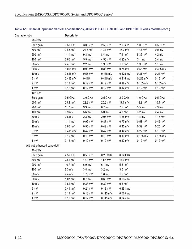
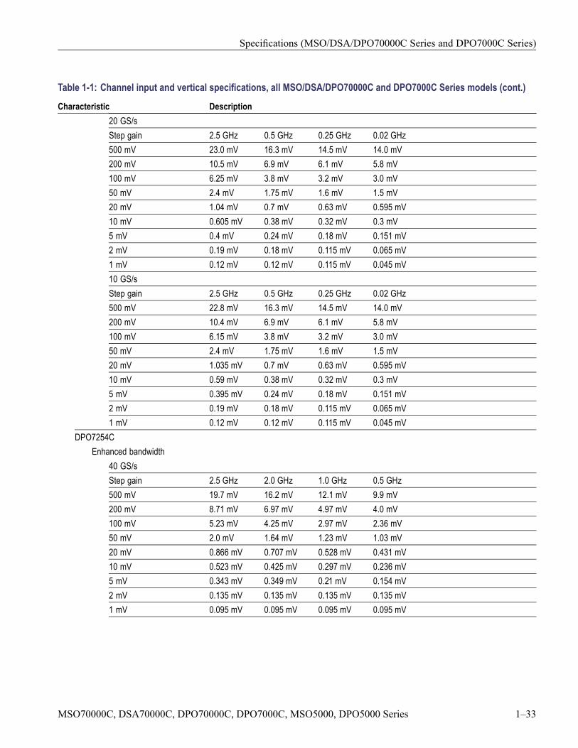
Noise, typical< 4 GHz models
Nondeterministic fluctuation in the displayed signal.
DPO7354CEnhanced bandwidth
40 GS/sStep gain 3.5 GHz 3.0 GHz 2.5 GHz 2.0 GHz 1.0 GHz 0.5 GHz500 mV 23.5 mV 20.2 mV 18.9 mV 16.5 mV 12.2 mV 9.7 mV200 mV 10.9 mV 9.2 mV 8.1 mV 7.05 mV 5.3 mV 4.1 mV100 mV 6.6 mV 5.4 mV 4.9 mV 4.2 mV 3.05 mV 2.35 mV50 mV 2.35 mV 2.1 mV 1.9 mV 1.7 mV 1.3 mV 1.0 mV20 mV 1.03 mV 0.89 mV 0.811 mV 0.72 mV 0.53 mV 0.43 mV10 mV 0.61 mV 0.55 mV 0.47 mV 0.42 mV 0.3 mV 0.23 mV5 mV 0.41 mV 0.415 mV 0.41 mV 0.4 mV 0.21 mV 0.16 mV2 mV 0.19 mV 0.19 mV 0.19 mV 0.19 mV 0.185 mV 0.185 mV1 mV 0.12 mV 0.12 mV 0.12 mV 0.12 mV 0.12 mV 0.12 mV
MSO70000C, DSA70000C, DPO70000C, DPO7000C, MSO5000, DPO5000 Series 1–31
Specifications (MSO/DSA/DPO70000C Series and DPO7000C Series)
Table 1-1: Channel input and vertical specifications, all MSO/DSA/DPO70000C and DPO7000C Series models (cont.)
Characteristic Description20 GS/sStep gain 3.5 GHz 3.0 GHz 2.5 GHz 2.0 GHz 1.0 GHz 0.5 GHz500 mV 24.3 mV 21.6 mV 19.1 mV 16.7 mV 12.4 mV 9.9 mV200 mV 11.1 mV 9.3 mV 8.4 mV 7.1 mV 5.35 mV 4.2 mV100 mV 6.65 mV 5.5 mV 4.95 mV 4.25 mV 3.1 mV 2.4 mV50 mV 2.45 mV 2.2 mV 1.95 mV 1.8 mV 1.35 mV 1.1 mV20 mV 1.055 mV 0.93 mV 0.83 mV 0.75 mV 0.55 mV 0.435 mV10 mV 0.625 mV 0.55 mV 0.475 mV 0.425 mV 0.31 mV 0.24 mV5 mV 0.415 mV 0.415 0.415 mV 0.415 mV 0.215 mV 0.16 mV2 mV 0.19 mV 0.19 mV 0.19 mV 0.19 mV 0.185 mV 0.185 mV1 mV 0.12 mV 0.12 mV 0.12 mV 0.12 mV 0.12 mV 0.12 mV10 GS/sStep gain 3.5 GHz 3.0 GHz 2.5 GHz 2.0 GHz 1.0 GHz 0.5 GHz500 mV 25.8 mV 22.2 mV 20.0 mV 17.7 mV 13.2 mV 10.4 mV200 mV 11.7 mV 9.9 mV 8.7 mV 7.5 mV 5.5 mV 4.3 mV100 mV 6.9 mV 5.6 mV 5.0 mV 4.3 mV 3.2 mV 2.4 mV50 mV 2.6 mV 2.3 mV 2.05 mV 1.85 mV 1.4 mV 1.15 mV20 mV 1.11 mV 0.99 mV 0.87 mV 0.77 mV 0.58 mV 0.45 mV10 mV 0.65 mV 0.55 mV 0.49 mV 0.43 mV 0.32 mV 0.25 mV5 mV 0.415 mV 0.42 mV 0.42 mV 0.42 mV 0.22 mV 0.16 mV2 mV 0.19 mV 0.19 mV 0.19 mV 0.19 mV 0.185 mV 0.185 mV1 mV 0.12 mV 0.12 mV 0.12 mV 0.12 mV 0.12 mV 0.12 mV
Without enhanced bandwidth40 GS/sStep gain 2.5 GHz 0.5 GHz 0.25 GHz 0.02 GHz500 mV 23.5 mV 16.3 mV 14.5 mV 14.0 mV200 mV 10.7 mV 6.9 mV 6.1 mV 5.8 mV100 mV 6.3 mV 3.8 mV 3.2 mV 3.0 mV50 mV 2.4 mV 1.75 mV 1.6 mV 1.5 mV20 mV 1.07 mV 0.7 mV 0.63 mV 0.595 mV10 mV 0.61 mV 0.38 mV 0.32 mV 0.3 mV5 mV 0.41 mV 0.24 mV 0.18 mV 0.151 mV2 mV 0.19 mV 0.18 mV 0.115 mV 0.065 mV1 mV 0.12 mV 0.12 mV 0.115 mV 0.045 mV
1–32 MSO70000C, DSA70000C, DPO70000C, DPO7000C, MSO5000, DPO5000 Series
Specifications (MSO/DSA/DPO70000C Series and DPO7000C Series)
Table 1-1: Channel input and vertical specifications, all MSO/DSA/DPO70000C and DPO7000C Series models (cont.)
Characteristic Description20 GS/sStep gain 2.5 GHz 0.5 GHz 0.25 GHz 0.02 GHz500 mV 23.0 mV 16.3 mV 14.5 mV 14.0 mV200 mV 10.5 mV 6.9 mV 6.1 mV 5.8 mV100 mV 6.25 mV 3.8 mV 3.2 mV 3.0 mV50 mV 2.4 mV 1.75 mV 1.6 mV 1.5 mV20 mV 1.04 mV 0.7 mV 0.63 mV 0.595 mV10 mV 0.605 mV 0.38 mV 0.32 mV 0.3 mV5 mV 0.4 mV 0.24 mV 0.18 mV 0.151 mV2 mV 0.19 mV 0.18 mV 0.115 mV 0.065 mV1 mV 0.12 mV 0.12 mV 0.115 mV 0.045 mV10 GS/sStep gain 2.5 GHz 0.5 GHz 0.25 GHz 0.02 GHz500 mV 22.8 mV 16.3 mV 14.5 mV 14.0 mV200 mV 10.4 mV 6.9 mV 6.1 mV 5.8 mV100 mV 6.15 mV 3.8 mV 3.2 mV 3.0 mV50 mV 2.4 mV 1.75 mV 1.6 mV 1.5 mV20 mV 1.035 mV 0.7 mV 0.63 mV 0.595 mV10 mV 0.59 mV 0.38 mV 0.32 mV 0.3 mV5 mV 0.395 mV 0.24 mV 0.18 mV 0.151 mV2 mV 0.19 mV 0.18 mV 0.115 mV 0.065 mV1 mV 0.12 mV 0.12 mV 0.115 mV 0.045 mV
DPO7254CEnhanced bandwidth
40 GS/sStep gain 2.5 GHz 2.0 GHz 1.0 GHz 0.5 GHz500 mV 19.7 mV 16.2 mV 12.1 mV 9.9 mV200 mV 8.71 mV 6.97 mV 4.97 mV 4.0 mV100 mV 5.23 mV 4.25 mV 2.97 mV 2.36 mV50 mV 2.0 mV 1.64 mV 1.23 mV 1.03 mV20 mV 0.866 mV 0.707 mV 0.528 mV 0.431 mV10 mV 0.523 mV 0.425 mV 0.297 mV 0.236 mV5 mV 0.343 mV 0.349 mV 0.21 mV 0.154 mV2 mV 0.135 mV 0.135 mV 0.135 mV 0.135 mV1 mV 0.095 mV 0.095 mV 0.095 mV 0.095 mV
MSO70000C, DSA70000C, DPO70000C, DPO7000C, MSO5000, DPO5000 Series 1–33
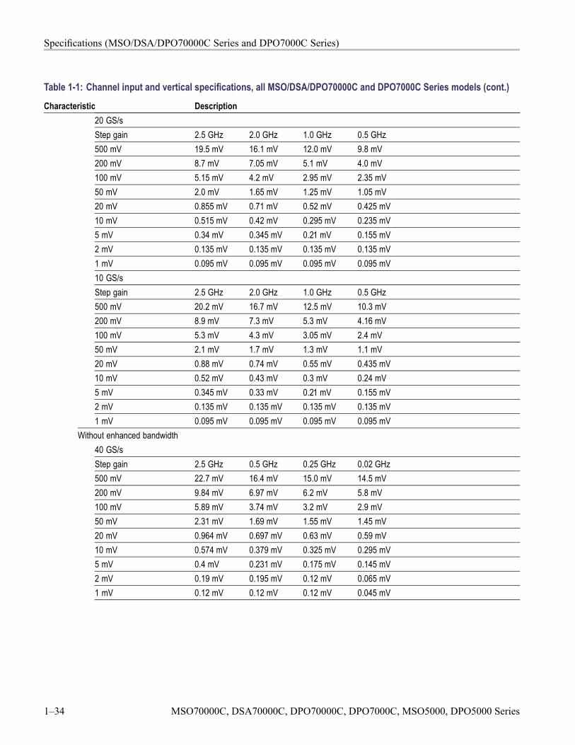
Specifications (MSO/DSA/DPO70000C Series and DPO7000C Series)
Table 1-1: Channel input and vertical specifications, all MSO/DSA/DPO70000C and DPO7000C Series models (cont.)
Characteristic Description20 GS/sStep gain 2.5 GHz 2.0 GHz 1.0 GHz 0.5 GHz500 mV 19.5 mV 16.1 mV 12.0 mV 9.8 mV200 mV 8.7 mV 7.05 mV 5.1 mV 4.0 mV100 mV 5.15 mV 4.2 mV 2.95 mV 2.35 mV50 mV 2.0 mV 1.65 mV 1.25 mV 1.05 mV20 mV 0.855 mV 0.71 mV 0.52 mV 0.425 mV10 mV 0.515 mV 0.42 mV 0.295 mV 0.235 mV5 mV 0.34 mV 0.345 mV 0.21 mV 0.155 mV2 mV 0.135 mV 0.135 mV 0.135 mV 0.135 mV1 mV 0.095 mV 0.095 mV 0.095 mV 0.095 mV10 GS/sStep gain 2.5 GHz 2.0 GHz 1.0 GHz 0.5 GHz500 mV 20.2 mV 16.7 mV 12.5 mV 10.3 mV200 mV 8.9 mV 7.3 mV 5.3 mV 4.16 mV100 mV 5.3 mV 4.3 mV 3.05 mV 2.4 mV50 mV 2.1 mV 1.7 mV 1.3 mV 1.1 mV20 mV 0.88 mV 0.74 mV 0.55 mV 0.435 mV10 mV 0.52 mV 0.43 mV 0.3 mV 0.24 mV5 mV 0.345 mV 0.33 mV 0.21 mV 0.155 mV2 mV 0.135 mV 0.135 mV 0.135 mV 0.135 mV1 mV 0.095 mV 0.095 mV 0.095 mV 0.095 mV
Without enhanced bandwidth40 GS/sStep gain 2.5 GHz 0.5 GHz 0.25 GHz 0.02 GHz500 mV 22.7 mV 16.4 mV 15.0 mV 14.5 mV200 mV 9.84 mV 6.97 mV 6.2 mV 5.8 mV100 mV 5.89 mV 3.74 mV 3.2 mV 2.9 mV50 mV 2.31 mV 1.69 mV 1.55 mV 1.45 mV20 mV 0.964 mV 0.697 mV 0.63 mV 0.59 mV10 mV 0.574 mV 0.379 mV 0.325 mV 0.295 mV5 mV 0.4 mV 0.231 mV 0.175 mV 0.145 mV2 mV 0.19 mV 0.195 mV 0.12 mV 0.065 mV1 mV 0.12 mV 0.12 mV 0.12 mV 0.045 mV
1–34 MSO70000C, DSA70000C, DPO70000C, DPO7000C, MSO5000, DPO5000 Series
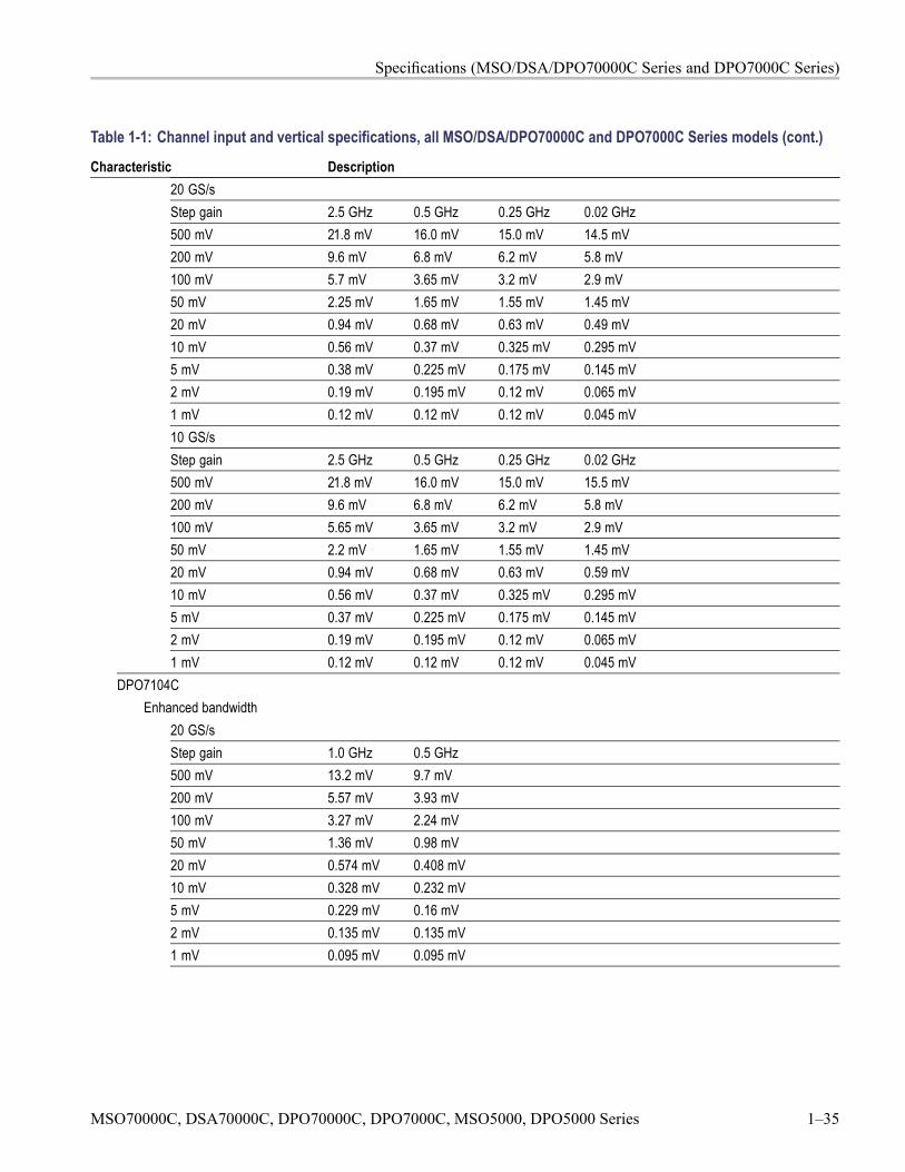
Specifications (MSO/DSA/DPO70000C Series and DPO7000C Series)
Table 1-1: Channel input and vertical specifications, all MSO/DSA/DPO70000C and DPO7000C Series models (cont.)
Characteristic Description20 GS/sStep gain 2.5 GHz 0.5 GHz 0.25 GHz 0.02 GHz500 mV 21.8 mV 16.0 mV 15.0 mV 14.5 mV200 mV 9.6 mV 6.8 mV 6.2 mV 5.8 mV100 mV 5.7 mV 3.65 mV 3.2 mV 2.9 mV50 mV 2.25 mV 1.65 mV 1.55 mV 1.45 mV20 mV 0.94 mV 0.68 mV 0.63 mV 0.49 mV10 mV 0.56 mV 0.37 mV 0.325 mV 0.295 mV5 mV 0.38 mV 0.225 mV 0.175 mV 0.145 mV2 mV 0.19 mV 0.195 mV 0.12 mV 0.065 mV1 mV 0.12 mV 0.12 mV 0.12 mV 0.045 mV10 GS/sStep gain 2.5 GHz 0.5 GHz 0.25 GHz 0.02 GHz500 mV 21.8 mV 16.0 mV 15.0 mV 15.5 mV200 mV 9.6 mV 6.8 mV 6.2 mV 5.8 mV100 mV 5.65 mV 3.65 mV 3.2 mV 2.9 mV50 mV 2.2 mV 1.65 mV 1.55 mV 1.45 mV20 mV 0.94 mV 0.68 mV 0.63 mV 0.59 mV10 mV 0.56 mV 0.37 mV 0.325 mV 0.295 mV5 mV 0.37 mV 0.225 mV 0.175 mV 0.145 mV2 mV 0.19 mV 0.195 mV 0.12 mV 0.065 mV1 mV 0.12 mV 0.12 mV 0.12 mV 0.045 mV
DPO7104CEnhanced bandwidth
20 GS/sStep gain 1.0 GHz 0.5 GHz500 mV 13.2 mV 9.7 mV200 mV 5.57 mV 3.93 mV100 mV 3.27 mV 2.24 mV50 mV 1.36 mV 0.98 mV20 mV 0.574 mV 0.408 mV10 mV 0.328 mV 0.232 mV5 mV 0.229 mV 0.16 mV2 mV 0.135 mV 0.135 mV1 mV 0.095 mV 0.095 mV
MSO70000C, DSA70000C, DPO70000C, DPO7000C, MSO5000, DPO5000 Series 1–35
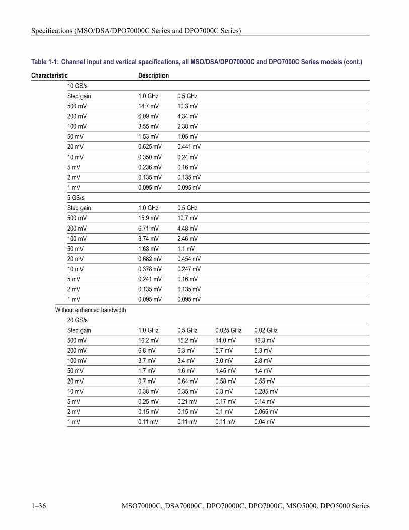
Specifications (MSO/DSA/DPO70000C Series and DPO7000C Series)
Table 1-1: Channel input and vertical specifications, all MSO/DSA/DPO70000C and DPO7000C Series models (cont.)
Characteristic Description10 GS/sStep gain 1.0 GHz 0.5 GHz500 mV 14.7 mV 10.3 mV200 mV 6.09 mV 4.34 mV100 mV 3.55 mV 2.38 mV50 mV 1.53 mV 1.05 mV20 mV 0.625 mV 0.441 mV10 mV 0.350 mV 0.24 mV5 mV 0.236 mV 0.16 mV2 mV 0.135 mV 0.135 mV1 mV 0.095 mV 0.095 mV5 GS/sStep gain 1.0 GHz 0.5 GHz500 mV 15.9 mV 10.7 mV200 mV 6.71 mV 4.48 mV100 mV 3.74 mV 2.46 mV50 mV 1.68 mV 1.1 mV20 mV 0.682 mV 0.454 mV10 mV 0.378 mV 0.247 mV5 mV 0.241 mV 0.16 mV2 mV 0.135 mV 0.135 mV1 mV 0.095 mV 0.095 mV
Without enhanced bandwidth20 GS/sStep gain 1.0 GHz 0.5 GHz 0.025 GHz 0.02 GHz500 mV 16.2 mV 15.2 mV 14.0 mV 13.3 mV200 mV 6.8 mV 6.3 mV 5.7 mV 5.3 mV100 mV 3.7 mV 3.4 mV 3.0 mV 2.8 mV50 mV 1.7 mV 1.6 mV 1.45 mV 1.4 mV20 mV 0.7 mV 0.64 mV 0.58 mV 0.55 mV10 mV 0.38 mV 0.35 mV 0.3 mV 0.285 mV5 mV 0.25 mV 0.21 mV 0.17 mV 0.14 mV2 mV 0.15 mV 0.15 mV 0.1 mV 0.065 mV1 mV 0.11 mV 0.11 mV 0.11 mV 0.04 mV
1–36 MSO70000C, DSA70000C, DPO70000C, DPO7000C, MSO5000, DPO5000 Series
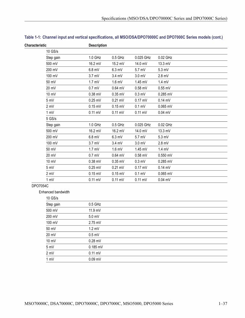
Specifications (MSO/DSA/DPO70000C Series and DPO7000C Series)
Table 1-1: Channel input and vertical specifications, all MSO/DSA/DPO70000C and DPO7000C Series models (cont.)
Characteristic Description10 GS/sStep gain 1.0 GHz 0.5 GHz 0.025 GHz 0.02 GHz500 mV 16.2 mV 15.2 mV 14.0 mV 13.3 mV200 mV 6.8 mV 6.3 mV 5.7 mV 5.3 mV100 mV 3.7 mV 3.4 mV 3.0 mV 2.8 mV50 mV 1.7 mV 1.6 mV 1.45 mV 1.4 mV20 mV 0.7 mV 0.64 mV 0.58 mV 0.55 mV10 mV 0.38 mV 0.35 mV 0.3 mV 0.285 mV5 mV 0.25 mV 0.21 mV 0.17 mV 0.14 mV2 mV 0.15 mV 0.15 mV 0.1 mV 0.065 mV1 mV 0.11 mV 0.11 mV 0.11 mV 0.04 mV5 GS/sStep gain 1.0 GHz 0.5 GHz 0.025 GHz 0.02 GHz500 mV 16.2 mV 16.2 mV 14.0 mV 13.3 mV200 mV 6.8 mV 6.3 mV 5.7 mV 5.3 mV100 mV 3.7 mV 3.4 mV 3.0 mV 2.8 mV50 mV 1.7 mV 1.6 mV 1.45 mV 1.4 mV20 mV 0.7 mV 0.64 mV 0.58 mV 0.550 mV10 mV 0.38 mV 0.35 mV 0.3 mV 0.285 mV5 mV 0.25 mV 0.21 mV 0.17 mV 0.14 mV2 mV 0.15 mV 0.15 mV 0.1 mV 0.065 mV1 mV 0.11 mV 0.11 mV 0.11 mV 0.04 mV
DPO7054CEnhanced bandwidth
10 GS/sStep gain 0.5 GHz500 mV 11.9 mV200 mV 5.0 mV100 mV 2.75 mV50 mV 1.2 mV20 mV 0.5 mV10 mV 0.28 mV5 mV 0.185 mV2 mV 0.11 mV1 mV 0.09 mV
MSO70000C, DSA70000C, DPO70000C, DPO7000C, MSO5000, DPO5000 Series 1–37
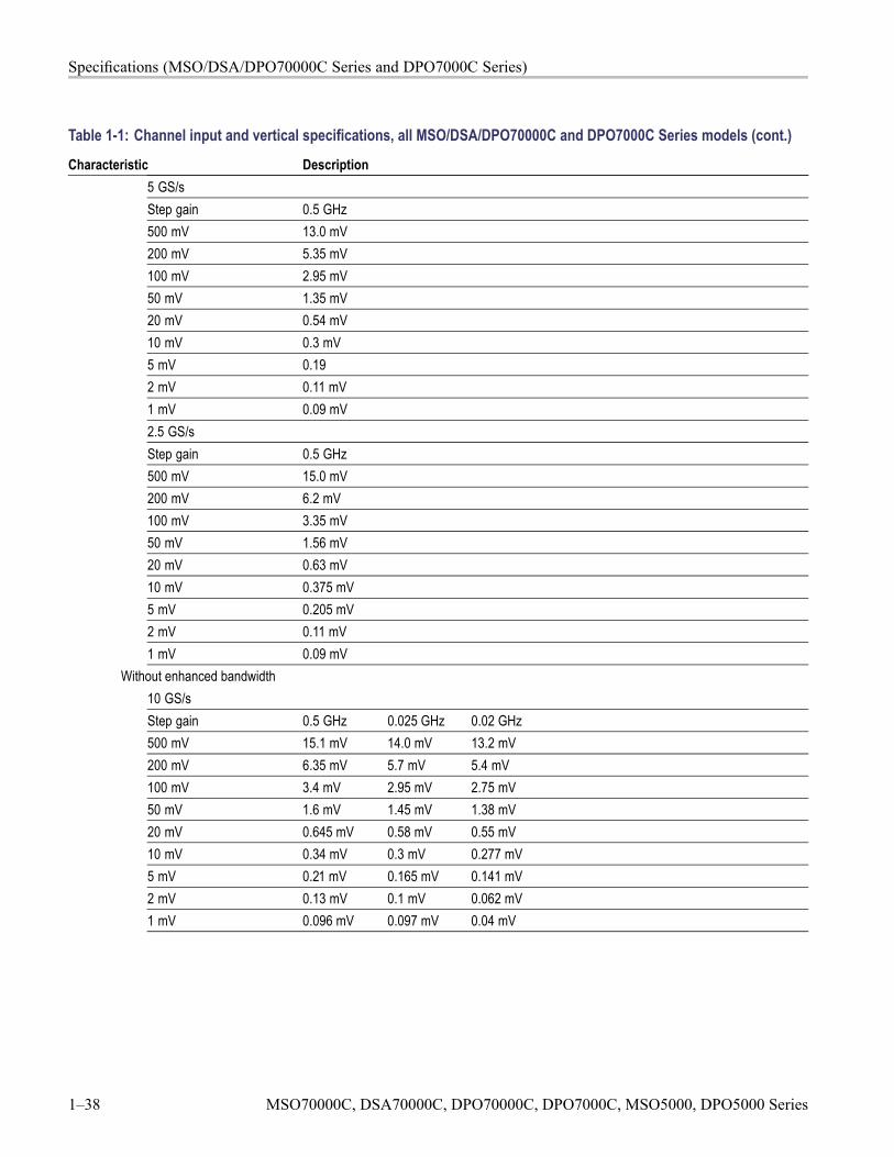
Specifications (MSO/DSA/DPO70000C Series and DPO7000C Series)
Table 1-1: Channel input and vertical specifications, all MSO/DSA/DPO70000C and DPO7000C Series models (cont.)
Characteristic Description5 GS/sStep gain 0.5 GHz500 mV 13.0 mV200 mV 5.35 mV100 mV 2.95 mV50 mV 1.35 mV20 mV 0.54 mV10 mV 0.3 mV5 mV 0.192 mV 0.11 mV1 mV 0.09 mV2.5 GS/sStep gain 0.5 GHz500 mV 15.0 mV200 mV 6.2 mV100 mV 3.35 mV50 mV 1.56 mV20 mV 0.63 mV10 mV 0.375 mV5 mV 0.205 mV2 mV 0.11 mV1 mV 0.09 mV
Without enhanced bandwidth10 GS/sStep gain 0.5 GHz 0.025 GHz 0.02 GHz500 mV 15.1 mV 14.0 mV 13.2 mV200 mV 6.35 mV 5.7 mV 5.4 mV100 mV 3.4 mV 2.95 mV 2.75 mV50 mV 1.6 mV 1.45 mV 1.38 mV20 mV 0.645 mV 0.58 mV 0.55 mV10 mV 0.34 mV 0.3 mV 0.277 mV5 mV 0.21 mV 0.165 mV 0.141 mV2 mV 0.13 mV 0.1 mV 0.062 mV1 mV 0.096 mV 0.097 mV 0.04 mV
1–38 MSO70000C, DSA70000C, DPO70000C, DPO7000C, MSO5000, DPO5000 Series
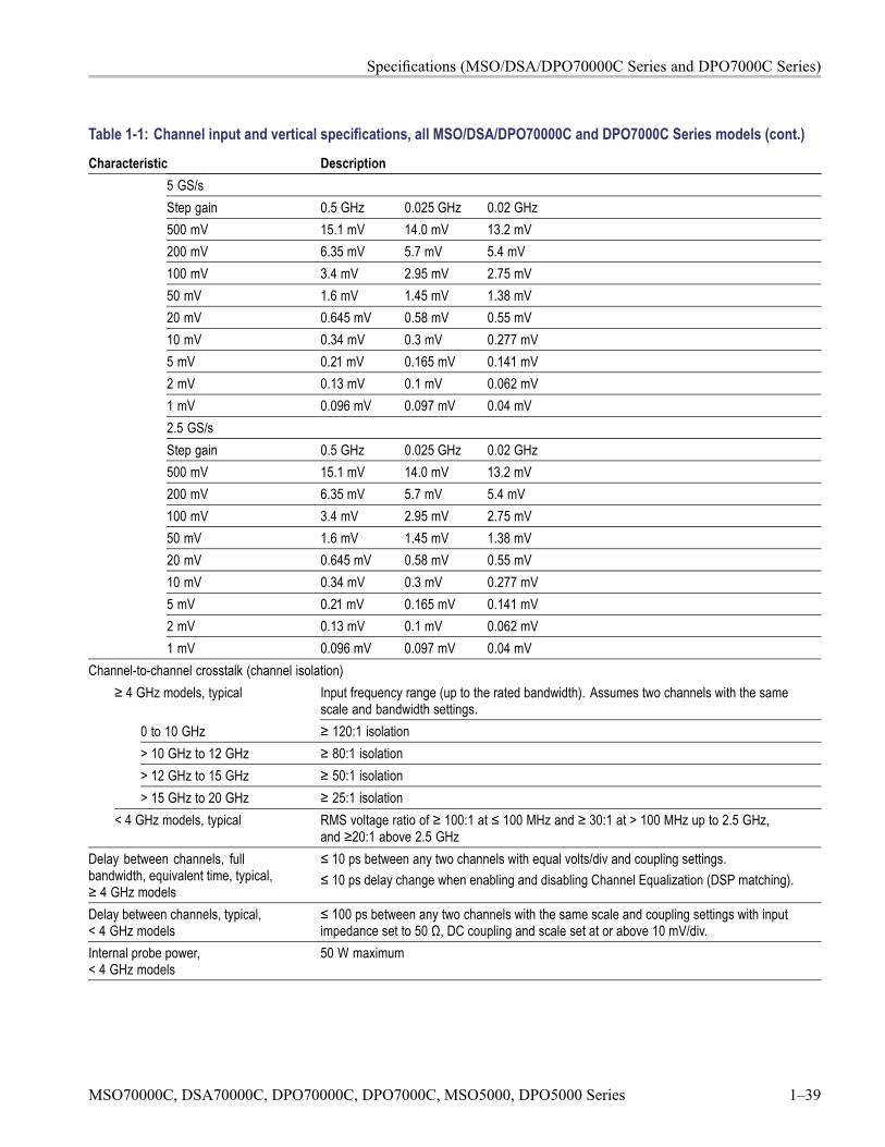
Specifications (MSO/DSA/DPO70000C Series and DPO7000C Series)
Table 1-1: Channel input and vertical specifications, all MSO/DSA/DPO70000C and DPO7000C Series models (cont.)
Characteristic Description5 GS/sStep gain 0.5 GHz 0.025 GHz 0.02 GHz500 mV 15.1 mV 14.0 mV 13.2 mV200 mV 6.35 mV 5.7 mV 5.4 mV100 mV 3.4 mV 2.95 mV 2.75 mV50 mV 1.6 mV 1.45 mV 1.38 mV20 mV 0.645 mV 0.58 mV 0.55 mV10 mV 0.34 mV 0.3 mV 0.277 mV5 mV 0.21 mV 0.165 mV 0.141 mV2 mV 0.13 mV 0.1 mV 0.062 mV1 mV 0.096 mV 0.097 mV 0.04 mV2.5 GS/sStep gain 0.5 GHz 0.025 GHz 0.02 GHz500 mV 15.1 mV 14.0 mV 13.2 mV200 mV 6.35 mV 5.7 mV 5.4 mV100 mV 3.4 mV 2.95 mV 2.75 mV50 mV 1.6 mV 1.45 mV 1.38 mV20 mV 0.645 mV 0.58 mV 0.55 mV10 mV 0.34 mV 0.3 mV 0.277 mV5 mV 0.21 mV 0.165 mV 0.141 mV2 mV 0.13 mV 0.1 mV 0.062 mV1 mV 0.096 mV 0.097 mV 0.04 mV
Channel-to-channel crosstalk (channel isolation)≥ 4 GHz models, typical Input frequency range (up to the rated bandwidth). Assumes two channels with the same
scale and bandwidth settings.0 to 10 GHz ≥ 120:1 isolation> 10 GHz to 12 GHz ≥ 80:1 isolation> 12 GHz to 15 GHz ≥ 50:1 isolation> 15 GHz to 20 GHz ≥ 25:1 isolation
< 4 GHz models, typical RMS voltage ratio of ≥ 100:1 at ≤ 100 MHz and ≥ 30:1 at > 100 MHz up to 2.5 GHz,and ≥20:1 above 2.5 GHz
Delay between channels, fullbandwidth, equivalent time, typical,≥ 4 GHz models
≤ 10 ps between any two channels with equal volts/div and coupling settings.≤ 10 ps delay change when enabling and disabling Channel Equalization (DSP matching).
Delay between channels, typical,< 4 GHz models
≤ 100 ps between any two channels with the same scale and coupling settings with inputimpedance set to 50 Ω, DC coupling and scale set at or above 10 mV/div.
Internal probe power,< 4 GHz models
50 W maximum
MSO70000C, DSA70000C, DPO70000C, DPO7000C, MSO5000, DPO5000 Series 1–39
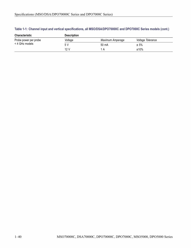
Specifications (MSO/DSA/DPO70000C Series and DPO7000C Series)
Table 1-1: Channel input and vertical specifications, all MSO/DSA/DPO70000C and DPO7000C Series models (cont.)
Characteristic DescriptionVoltage Maximum Amperage Voltage ToleranceProbe power per probe
< 4 GHz models 5 V12 V
50 mA1 A
± 5%±10%
1–40 MSO70000C, DSA70000C, DPO70000C, DPO7000C, MSO5000, DPO5000 Series
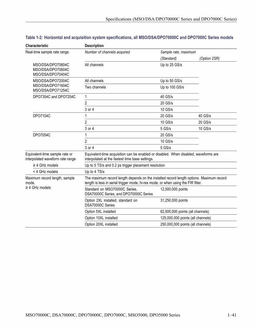
Specifications (MSO/DSA/DPO70000C Series and DPO7000C Series)
Table 1-2: Horizontal and acquisition system specifications, all MSO/DSA/DPO70000C and DPO7000C Series modelsCharacteristic Description
Sample rate, maximumReal-time sample rate range Number of channels acquired(Standard) (Option 2SR)
MSO/DSA/DPO70804CMSO/DSA/DPO70604CMSO/DSA/DPO70404C
All channels Up to 25 GS/s
All channels Up to 50 GS/sMSO/DSA/DPO72004CMSO/DSA/DPO71604CMSO/DSA/DPO71254C
Two channels Up to 100 GS/s
1 40 GS/s2 20 GS/s
DPO7354C and DPO7254C
3 or 4 10 GS/s1 20 GS/s 40 GS/s2 10 GS/s 20 GS/s
DPO7104C
3 or 4 5 GS/s 10 GS/s1 20 GS/s2 10 GS/s
DPO7054C
3 or 4 5 GS/sEquivalent-time sample rate orinterpolated waveform rate range
Equivalent-time acquisition can be enabled or disabled. When disabled, waveforms areinterpolated at the fastest time base settings.
≥ 4 GHz models Up to 5 TS/s and 0.2 ps trigger placement resolution< 4 GHz models Up to 4 TS/s
The maximum record length depends on the installed record length options. Maximum recordlength is less in serial trigger mode, hi-res mode, or when using the FIR filter.Standard on MSO70000C Series,DSA70000C Series, and DPO70000C Series
12,500,000 points
Option 2XL installed, standard onDSA70000C Series
31,250,000 points
Option 5XL installed 62,500,000 points (all channels)Option 10XL installed 125,000,000 points (all channels)
Maximum record length, samplemode,≥ 4 GHz models
Option 20XL installed 250,000,000 points (all channels)
MSO70000C, DSA70000C, DPO70000C, DPO7000C, MSO5000, DPO5000 Series 1–41
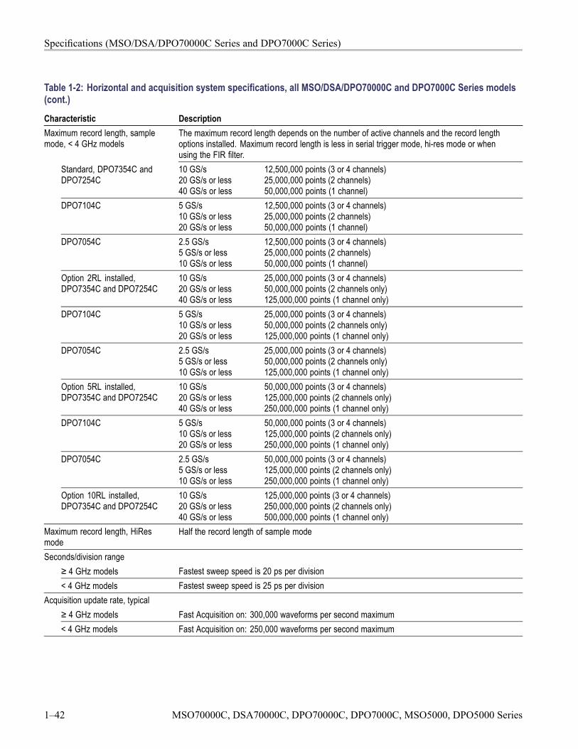
Specifications (MSO/DSA/DPO70000C Series and DPO7000C Series)
Table 1-2: Horizontal and acquisition system specifications, all MSO/DSA/DPO70000C and DPO7000C Series models(cont.)
Characteristic DescriptionMaximum record length, samplemode, < 4 GHz models
The maximum record length depends on the number of active channels and the record lengthoptions installed. Maximum record length is less in serial trigger mode, hi-res mode or whenusing the FIR filter.
Standard, DPO7354C andDPO7254C
10 GS/s20 GS/s or less40 GS/s or less
12,500,000 points (3 or 4 channels)25,000,000 points (2 channels)50,000,000 points (1 channel)
DPO7104C 5 GS/s10 GS/s or less20 GS/s or less
12,500,000 points (3 or 4 channels)25,000,000 points (2 channels)50,000,000 points (1 channel)
DPO7054C 2.5 GS/s5 GS/s or less10 GS/s or less
12,500,000 points (3 or 4 channels)25,000,000 points (2 channels)50,000,000 points (1 channel)
Option 2RL installed,DPO7354C and DPO7254C
10 GS/s20 GS/s or less40 GS/s or less
25,000,000 points (3 or 4 channels)50,000,000 points (2 channels only)125,000,000 points (1 channel only)
DPO7104C 5 GS/s10 GS/s or less20 GS/s or less
25,000,000 points (3 or 4 channels)50,000,000 points (2 channels only)125,000,000 points (1 channel only)
DPO7054C 2.5 GS/s5 GS/s or less10 GS/s or less
25,000,000 points (3 or 4 channels)50,000,000 points (2 channels only)125,000,000 points (1 channel only)
Option 5RL installed,DPO7354C and DPO7254C
10 GS/s20 GS/s or less40 GS/s or less
50,000,000 points (3 or 4 channels)125,000,000 points (2 channels only)250,000,000 points (1 channel only)
DPO7104C 5 GS/s10 GS/s or less20 GS/s or less
50,000,000 points (3 or 4 channels)125,000,000 points (2 channels only)250,000,000 points (1 channel only)
DPO7054C 2.5 GS/s5 GS/s or less10 GS/s or less
50,000,000 points (3 or 4 channels)125,000,000 points (2 channels only)250,000,000 points (1 channel only)
Option 10RL installed,DPO7354C and DPO7254C
10 GS/s20 GS/s or less40 GS/s or less
125,000,000 points (3 or 4 channels)250,000,000 points (2 channels only)500,000,000 points (1 channel only)
Maximum record length, HiResmode
Half the record length of sample mode
Seconds/division range≥ 4 GHz models Fastest sweep speed is 20 ps per division< 4 GHz models Fastest sweep speed is 25 ps per division
Acquisition update rate, typical≥ 4 GHz models Fast Acquisition on: 300,000 waveforms per second maximum< 4 GHz models Fast Acquisition on: 250,000 waveforms per second maximum
1–42 MSO70000C, DSA70000C, DPO70000C, DPO7000C, MSO5000, DPO5000 Series
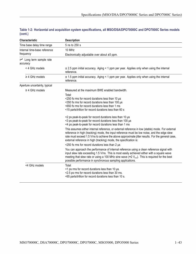
Specifications (MSO/DSA/DPO70000C Series and DPO7000C Series)
Table 1-2: Horizontal and acquisition system specifications, all MSO/DSA/DPO70000C and DPO7000C Series models(cont.)
Characteristic DescriptionTime base delay time range 5 ns to 250 sInternal time-base referencefrequency
10 MHzElectronically adjustable over about ±5 ppm.
Long term sample rateaccuracy
< 4 GHz models ± 2.5 ppm initial accuracy. Aging < 1 ppm per year. Applies only when using the internalreference.
≥ 4 GHz models ± 1.5 ppm initial accuracy. Aging < 1 ppm per year. Applies only when using the internalreference.
Aperture uncertainty, typical≥ 4 GHz models Measured at the maximum BWE enabled bandwidth.
Total:<250 fs rms for record durations less than 10 μs<350 fs rms for record durations less than 100 μs<650 fs rms for record durations less than 1 ms<15 parts/trillion for record durations less than 60 s
<2 ps peak-to-peak for record durations less than 10 μs<3 ps peak-to-peak for record durations less than 100 μs<4 ps peak-to-peak for record durations less than 1 msThis assumes either internal reference, or external reference in low (stable) mode. For externalreference in high (tracking) mode, the input reference must be low noise, and the edge slewrate must exceed 1.5 V/ns to achieve the above approximate jitter results. For the general case,external reference in high (tracking) mode, the specification is:<250 fs rms for record durations less than 2 μsYou can approach the performance of internal reference using a clean reference signal withinput slew rate exceeding 1.5 V/ns. This is most easily achieved either with a square wavemeeting that slew rate or using a 100 MHz sine wave (≈2 Vp-p). This is required for the bestpossible performance in synchronous sampling applications.
<4 GHz models Total:<1 ps rms for record durations less than 10 μs.<2.5 ps rms for record durations less than 30 ms.<65 parts/trillion for record durations less than 10 s.
MSO70000C, DSA70000C, DPO70000C, DPO7000C, MSO5000, DPO5000 Series 1–43
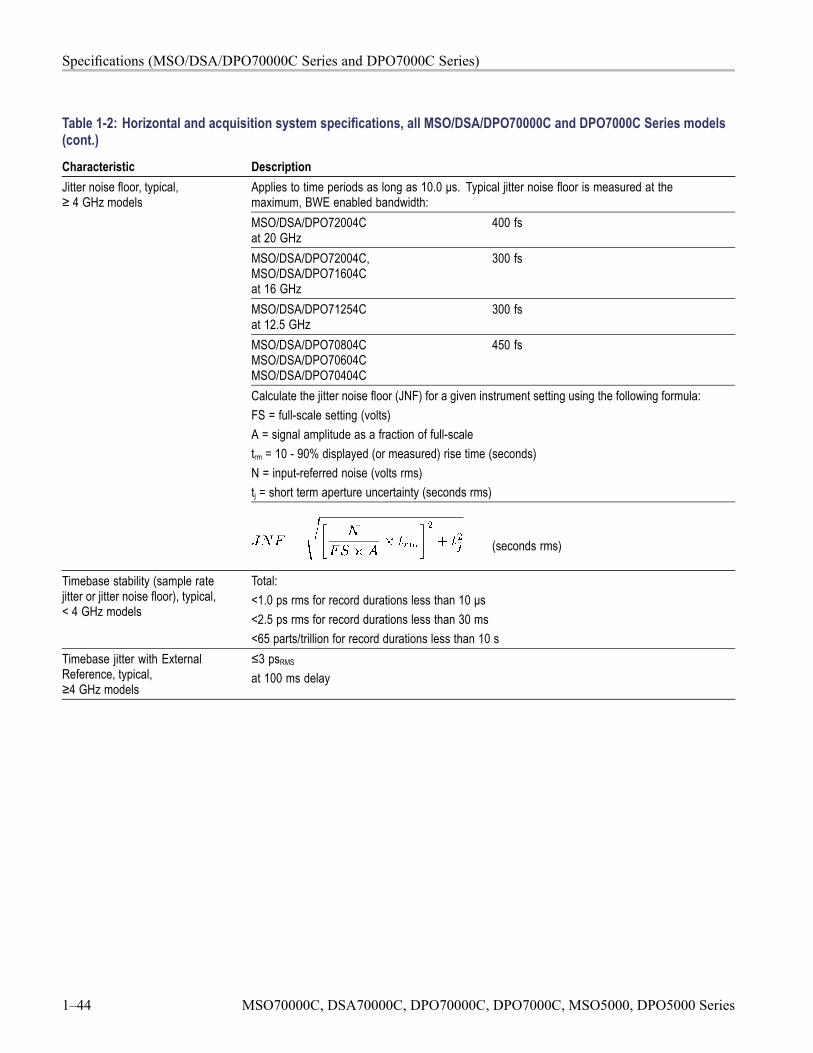
Specifications (MSO/DSA/DPO70000C Series and DPO7000C Series)
Table 1-2: Horizontal and acquisition system specifications, all MSO/DSA/DPO70000C and DPO7000C Series models(cont.)
Characteristic DescriptionApplies to time periods as long as 10.0 μs. Typical jitter noise floor is measured at themaximum, BWE enabled bandwidth:MSO/DSA/DPO72004Cat 20 GHz
400 fs
MSO/DSA/DPO72004C,MSO/DSA/DPO71604Cat 16 GHz
300 fs
MSO/DSA/DPO71254Cat 12.5 GHz
300 fs
MSO/DSA/DPO70804CMSO/DSA/DPO70604CMSO/DSA/DPO70404C
450 fs
Calculate the jitter noise floor (JNF) for a given instrument setting using the following formula:FS = full-scale setting (volts)A = signal amplitude as a fraction of full-scaletrm = 10 - 90% displayed (or measured) rise time (seconds)N = input-referred noise (volts rms)tj = short term aperture uncertainty (seconds rms)
Jitter noise floor, typical,≥ 4 GHz models
(seconds rms)
Timebase stability (sample ratejitter or jitter noise floor), typical,< 4 GHz models
Total:<1.0 ps rms for record durations less than 10 μs<2.5 ps rms for record durations less than 30 ms<65 parts/trillion for record durations less than 10 s
Timebase jitter with ExternalReference, typical,≥4 GHz models
≤3 psRMS
at 100 ms delay
1–44 MSO70000C, DSA70000C, DPO70000C, DPO7000C, MSO5000, DPO5000 Series
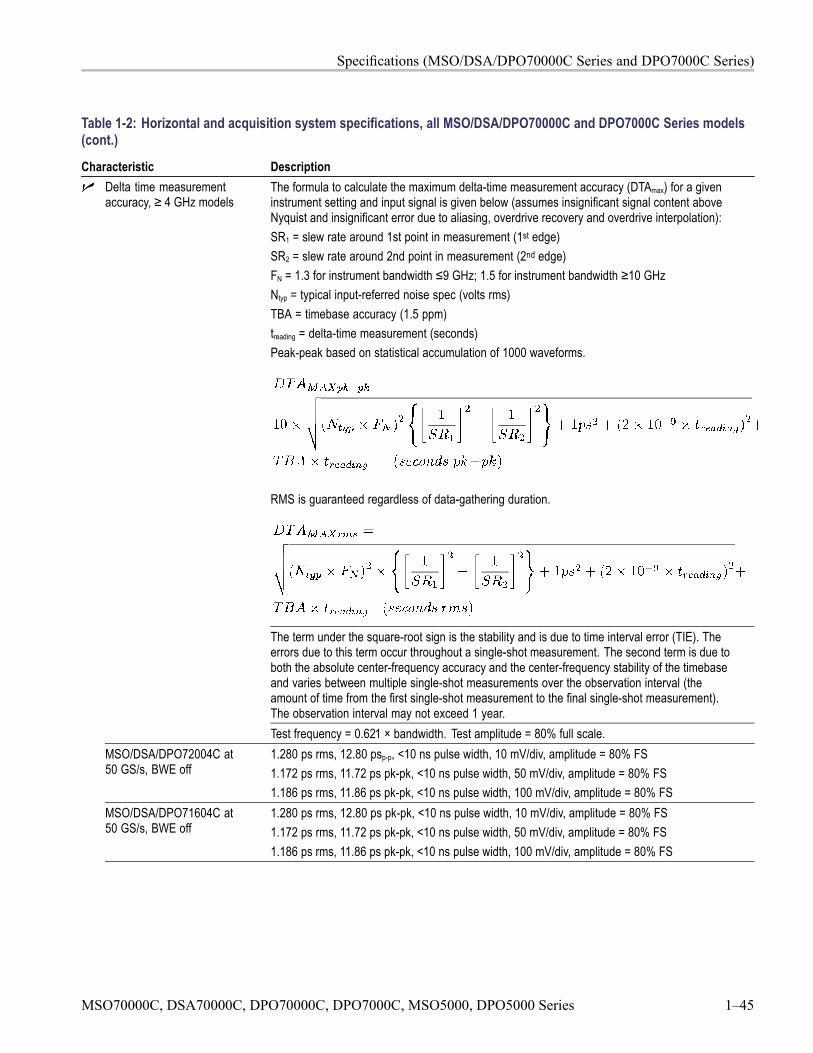
Specifications (MSO/DSA/DPO70000C Series and DPO7000C Series)
Table 1-2: Horizontal and acquisition system specifications, all MSO/DSA/DPO70000C and DPO7000C Series models(cont.)
Characteristic DescriptionDelta time measurementaccuracy, ≥ 4 GHz models
The formula to calculate the maximum delta-time measurement accuracy (DTAmax) for a giveninstrument setting and input signal is given below (assumes insignificant signal content aboveNyquist and insignificant error due to aliasing, overdrive recovery and overdrive interpolation):SR1 = slew rate around 1st point in measurement (1st edge)SR2 = slew rate around 2nd point in measurement (2nd edge)FN = 1.3 for instrument bandwidth ≤9 GHz; 1.5 for instrument bandwidth ≥10 GHzNtyp = typical input-referred noise spec (volts rms)TBA = timebase accuracy (1.5 ppm)treading = delta-time measurement (seconds)Peak-peak based on statistical accumulation of 1000 waveforms.
RMS is guaranteed regardless of data-gathering duration.
The term under the square-root sign is the stability and is due to time interval error (TIE). Theerrors due to this term occur throughout a single-shot measurement. The second term is due toboth the absolute center-frequency accuracy and the center-frequency stability of the timebaseand varies between multiple single-shot measurements over the observation interval (theamount of time from the first single-shot measurement to the final single-shot measurement).The observation interval may not exceed 1 year.Test frequency = 0.621 × bandwidth. Test amplitude = 80% full scale.
MSO/DSA/DPO72004C at50 GS/s, BWE off
1.280 ps rms, 12.80 psp-p, <10 ns pulse width, 10 mV/div, amplitude = 80% FS1.172 ps rms, 11.72 ps pk-pk, <10 ns pulse width, 50 mV/div, amplitude = 80% FS1.186 ps rms, 11.86 ps pk-pk, <10 ns pulse width, 100 mV/div, amplitude = 80% FS
MSO/DSA/DPO71604C at50 GS/s, BWE off
1.280 ps rms, 12.80 ps pk-pk, <10 ns pulse width, 10 mV/div, amplitude = 80% FS1.172 ps rms, 11.72 ps pk-pk, <10 ns pulse width, 50 mV/div, amplitude = 80% FS1.186 ps rms, 11.86 ps pk-pk, <10 ns pulse width, 100 mV/div, amplitude = 80% FS
MSO70000C, DSA70000C, DPO70000C, DPO7000C, MSO5000, DPO5000 Series 1–45
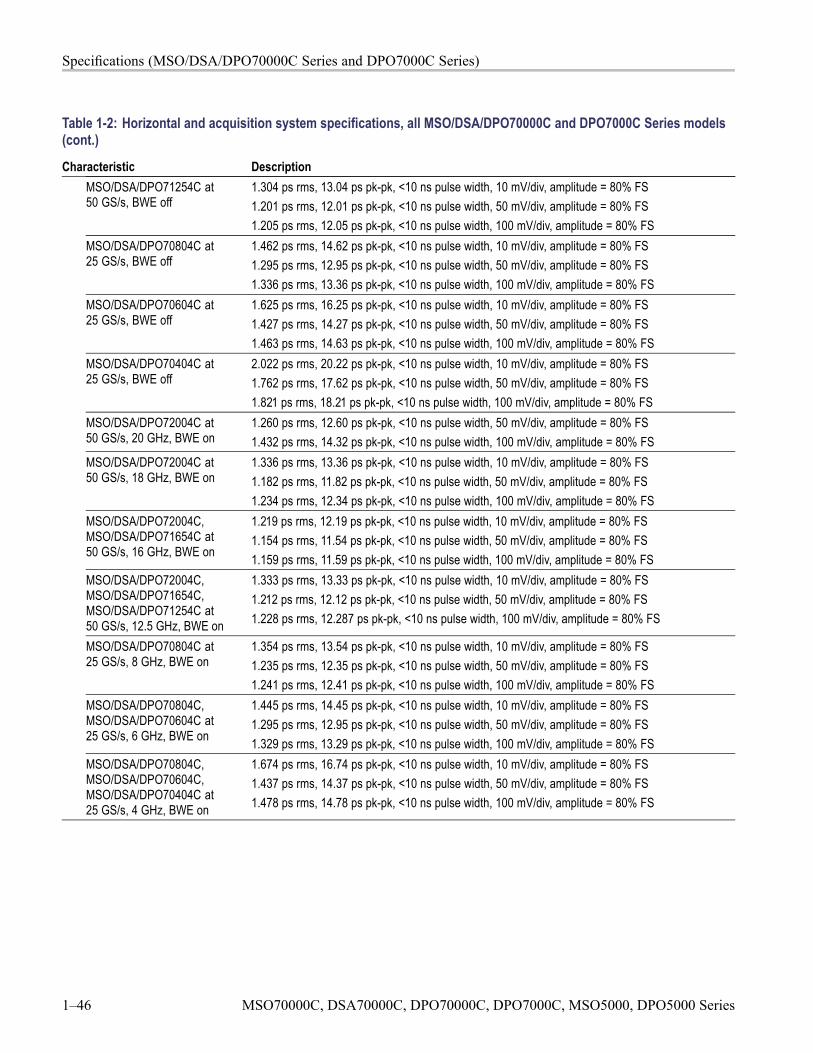
Specifications (MSO/DSA/DPO70000C Series and DPO7000C Series)
Table 1-2: Horizontal and acquisition system specifications, all MSO/DSA/DPO70000C and DPO7000C Series models(cont.)
Characteristic DescriptionMSO/DSA/DPO71254C at50 GS/s, BWE off
1.304 ps rms, 13.04 ps pk-pk, <10 ns pulse width, 10 mV/div, amplitude = 80% FS1.201 ps rms, 12.01 ps pk-pk, <10 ns pulse width, 50 mV/div, amplitude = 80% FS1.205 ps rms, 12.05 ps pk-pk, <10 ns pulse width, 100 mV/div, amplitude = 80% FS
MSO/DSA/DPO70804C at25 GS/s, BWE off
1.462 ps rms, 14.62 ps pk-pk, <10 ns pulse width, 10 mV/div, amplitude = 80% FS1.295 ps rms, 12.95 ps pk-pk, <10 ns pulse width, 50 mV/div, amplitude = 80% FS1.336 ps rms, 13.36 ps pk-pk, <10 ns pulse width, 100 mV/div, amplitude = 80% FS
MSO/DSA/DPO70604C at25 GS/s, BWE off
1.625 ps rms, 16.25 ps pk-pk, <10 ns pulse width, 10 mV/div, amplitude = 80% FS1.427 ps rms, 14.27 ps pk-pk, <10 ns pulse width, 50 mV/div, amplitude = 80% FS1.463 ps rms, 14.63 ps pk-pk, <10 ns pulse width, 100 mV/div, amplitude = 80% FS
MSO/DSA/DPO70404C at25 GS/s, BWE off
2.022 ps rms, 20.22 ps pk-pk, <10 ns pulse width, 10 mV/div, amplitude = 80% FS1.762 ps rms, 17.62 ps pk-pk, <10 ns pulse width, 50 mV/div, amplitude = 80% FS1.821 ps rms, 18.21 ps pk-pk, <10 ns pulse width, 100 mV/div, amplitude = 80% FS
MSO/DSA/DPO72004C at50 GS/s, 20 GHz, BWE on
1.260 ps rms, 12.60 ps pk-pk, <10 ns pulse width, 50 mV/div, amplitude = 80% FS1.432 ps rms, 14.32 ps pk-pk, <10 ns pulse width, 100 mV/div, amplitude = 80% FS
MSO/DSA/DPO72004C at50 GS/s, 18 GHz, BWE on
1.336 ps rms, 13.36 ps pk-pk, <10 ns pulse width, 10 mV/div, amplitude = 80% FS1.182 ps rms, 11.82 ps pk-pk, <10 ns pulse width, 50 mV/div, amplitude = 80% FS1.234 ps rms, 12.34 ps pk-pk, <10 ns pulse width, 100 mV/div, amplitude = 80% FS
MSO/DSA/DPO72004C,MSO/DSA/DPO71654C at50 GS/s, 16 GHz, BWE on
1.219 ps rms, 12.19 ps pk-pk, <10 ns pulse width, 10 mV/div, amplitude = 80% FS1.154 ps rms, 11.54 ps pk-pk, <10 ns pulse width, 50 mV/div, amplitude = 80% FS1.159 ps rms, 11.59 ps pk-pk, <10 ns pulse width, 100 mV/div, amplitude = 80% FS
MSO/DSA/DPO72004C,MSO/DSA/DPO71654C,MSO/DSA/DPO71254C at50 GS/s, 12.5 GHz, BWE on
1.333 ps rms, 13.33 ps pk-pk, <10 ns pulse width, 10 mV/div, amplitude = 80% FS1.212 ps rms, 12.12 ps pk-pk, <10 ns pulse width, 50 mV/div, amplitude = 80% FS1.228 ps rms, 12.287 ps pk-pk, <10 ns pulse width, 100 mV/div, amplitude = 80% FS
MSO/DSA/DPO70804C at25 GS/s, 8 GHz, BWE on
1.354 ps rms, 13.54 ps pk-pk, <10 ns pulse width, 10 mV/div, amplitude = 80% FS1.235 ps rms, 12.35 ps pk-pk, <10 ns pulse width, 50 mV/div, amplitude = 80% FS1.241 ps rms, 12.41 ps pk-pk, <10 ns pulse width, 100 mV/div, amplitude = 80% FS
MSO/DSA/DPO70804C,MSO/DSA/DPO70604C at25 GS/s, 6 GHz, BWE on
1.445 ps rms, 14.45 ps pk-pk, <10 ns pulse width, 10 mV/div, amplitude = 80% FS1.295 ps rms, 12.95 ps pk-pk, <10 ns pulse width, 50 mV/div, amplitude = 80% FS1.329 ps rms, 13.29 ps pk-pk, <10 ns pulse width, 100 mV/div, amplitude = 80% FS
MSO/DSA/DPO70804C,MSO/DSA/DPO70604C,MSO/DSA/DPO70404C at25 GS/s, 4 GHz, BWE on
1.674 ps rms, 16.74 ps pk-pk, <10 ns pulse width, 10 mV/div, amplitude = 80% FS1.437 ps rms, 14.37 ps pk-pk, <10 ns pulse width, 50 mV/div, amplitude = 80% FS1.478 ps rms, 14.78 ps pk-pk, <10 ns pulse width, 100 mV/div, amplitude = 80% FS
1–46 MSO70000C, DSA70000C, DPO70000C, DPO7000C, MSO5000, DPO5000 Series
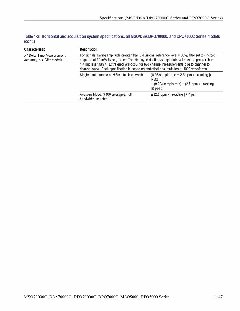
Specifications (MSO/DSA/DPO70000C Series and DPO7000C Series)
Table 1-2: Horizontal and acquisition system specifications, all MSO/DSA/DPO70000C and DPO7000C Series models(cont.)
Characteristic DescriptionFor signals having amplitude greater than 5 divisions, reference level = 50%, filter set to sin(x)/x,acquired at 10 mV/div or greater. The displayed risetime/sample interval must be greater than1.4 but less than 4. Extra error will occur for two channel measurements due to channel tochannel skew. Peak specification is based on statistical accumulation of 1000 waveforms.Single shot, sample or HiRes, full bandwidth (0.06/sample rate + 2.5 ppm x | reading |)
RMS± (0.30/(sample rate) + (2.5 ppm x | reading|)) peak
Delta Time MeasurementAccuracy, < 4 GHz models
Average Mode, ≥100 averages, fullbandwidth selected.
± (2.5 ppm x | reading | + 4 ps)
MSO70000C, DSA70000C, DPO70000C, DPO7000C, MSO5000, DPO5000 Series 1–47
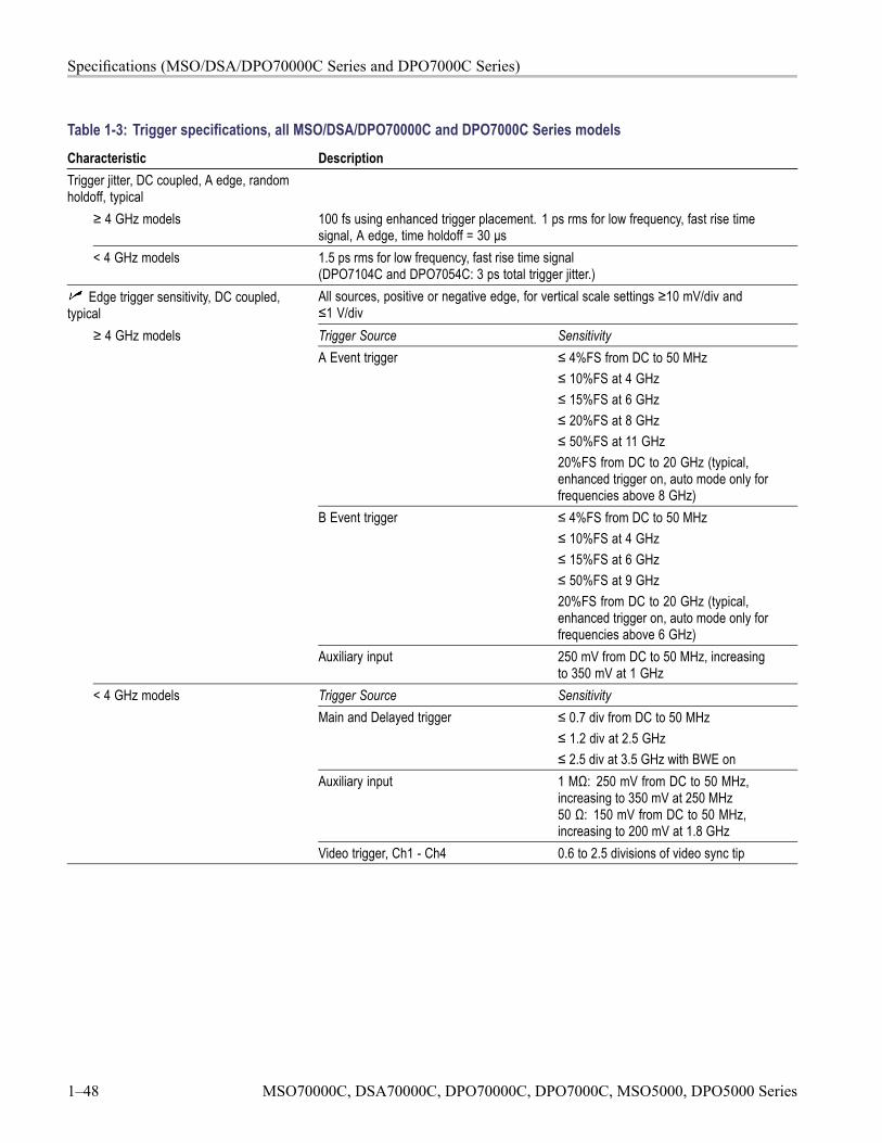
Specifications (MSO/DSA/DPO70000C Series and DPO7000C Series)
Table 1-3: Trigger specifications, all MSO/DSA/DPO70000C and DPO7000C Series modelsCharacteristic DescriptionTrigger jitter, DC coupled, A edge, randomholdoff, typical
≥ 4 GHz models 100 fs using enhanced trigger placement. 1 ps rms for low frequency, fast rise timesignal, A edge, time holdoff = 30 μs
< 4 GHz models 1.5 ps rms for low frequency, fast rise time signal(DPO7104C and DPO7054C: 3 ps total trigger jitter.)
Edge trigger sensitivity, DC coupled,typical
All sources, positive or negative edge, for vertical scale settings ≥10 mV/div and≤1 V/divTrigger Source SensitivityA Event trigger ≤ 4%FS from DC to 50 MHz
≤ 10%FS at 4 GHz≤ 15%FS at 6 GHz≤ 20%FS at 8 GHz≤ 50%FS at 11 GHz20%FS from DC to 20 GHz (typical,enhanced trigger on, auto mode only forfrequencies above 8 GHz)
B Event trigger ≤ 4%FS from DC to 50 MHz≤ 10%FS at 4 GHz≤ 15%FS at 6 GHz≤ 50%FS at 9 GHz20%FS from DC to 20 GHz (typical,enhanced trigger on, auto mode only forfrequencies above 6 GHz)
≥ 4 GHz models
Auxiliary input 250 mV from DC to 50 MHz, increasingto 350 mV at 1 GHz
Trigger Source SensitivityMain and Delayed trigger ≤ 0.7 div from DC to 50 MHz
≤ 1.2 div at 2.5 GHz≤ 2.5 div at 3.5 GHz with BWE on
Auxiliary input 1 MΩ: 250 mV from DC to 50 MHz,increasing to 350 mV at 250 MHz50 Ω: 150 mV from DC to 50 MHz,increasing to 200 mV at 1.8 GHz
< 4 GHz models
Video trigger, Ch1 - Ch4 0.6 to 2.5 divisions of video sync tip
1–48 MSO70000C, DSA70000C, DPO70000C, DPO7000C, MSO5000, DPO5000 Series
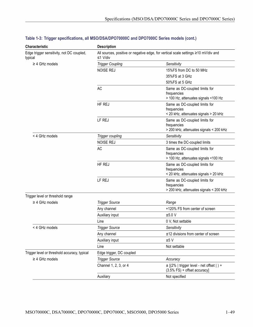
Specifications (MSO/DSA/DPO70000C Series and DPO7000C Series)
Table 1-3: Trigger specifications, all MSO/DSA/DPO70000C and DPO7000C Series models (cont.)
Characteristic DescriptionEdge trigger sensitivity, not DC coupled,typical
All sources, positive or negative edge, for vertical scale settings ≥10 mV/div and≤1 V/divTrigger Coupling SensitivityNOISE REJ 15%FS from DC to 50 MHz
35%FS at 3 GHz50%FS at 5 GHz
AC Same as DC-coupled limits forfrequencies> 100 Hz, attenuates signals <100 Hz
HF REJ Same as DC-coupled limits forfrequencies< 20 kHz, attenuates signals > 20 kHz
≥ 4 GHz models
LF REJ Same as DC-coupled limits forfrequencies> 200 kHz, attenuates signals < 200 kHz
Trigger coupling SensitivityNOISE REJ 3 times the DC-coupled limitsAC Same as DC-coupled limits for
frequencies> 100 Hz, attenuates signals <100 Hz
HF REJ Same as DC-coupled limits forfrequencies< 20 kHz, attenuates signals > 20 kHz
< 4 GHz models
LF REJ Same as DC-coupled limits forfrequencies> 200 kHz, attenuates signals < 200 kHz
Trigger level or threshold rangeTrigger Source RangeAny channel +120% FS from center of screenAuxiliary input ±5.0 V
≥ 4 GHz models
Line 0 V, Not settableTrigger Source SensitivityAny channel ±12 divisions from center of screenAuxiliary input ±5 V
< 4 GHz models
Line Not settableTrigger level or threshold accuracy, typical Edge trigger, DC coupled
Trigger Source AccuracyChannel 1, 2, 3, or 4 ± [(2% | trigger level - net offset | ) +
(3.5% FS) + offset accuracy]
≥ 4 GHz models
Auxiliary Not specified
MSO70000C, DSA70000C, DPO70000C, DPO7000C, MSO5000, DPO5000 Series 1–49
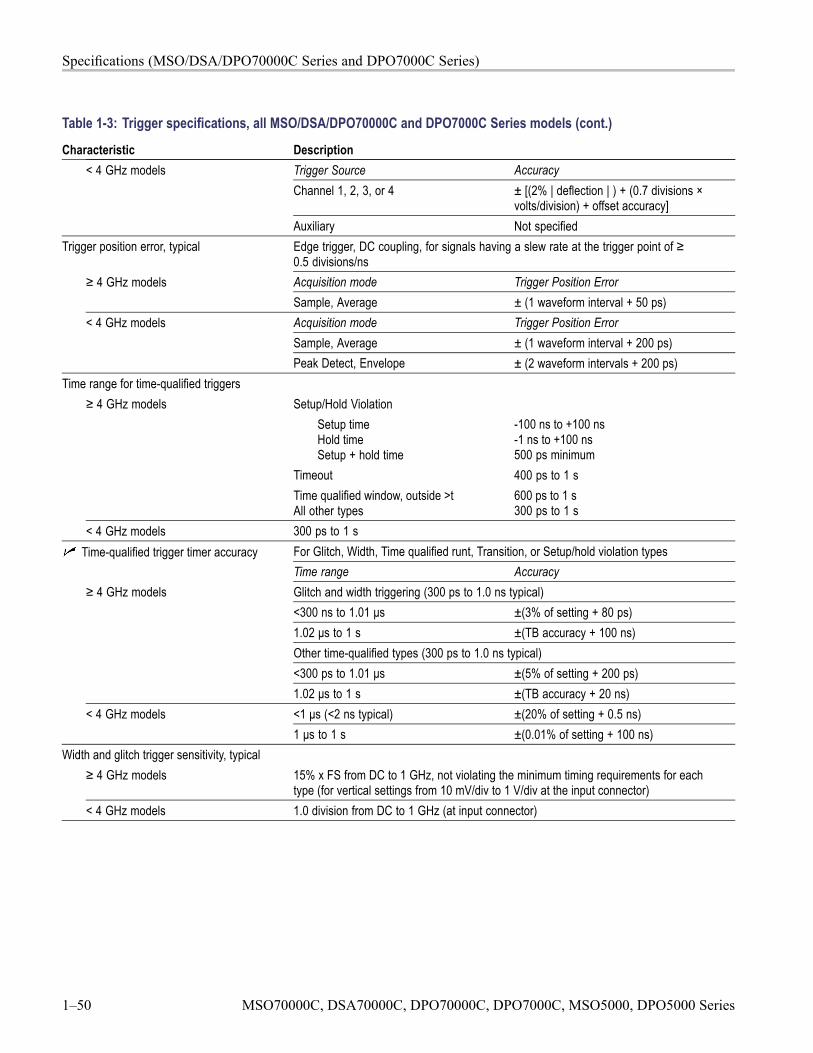
Specifications (MSO/DSA/DPO70000C Series and DPO7000C Series)
Table 1-3: Trigger specifications, all MSO/DSA/DPO70000C and DPO7000C Series models (cont.)
Characteristic DescriptionTrigger Source AccuracyChannel 1, 2, 3, or 4 ± [(2% | deflection | ) + (0.7 divisions ×
volts/division) + offset accuracy]
< 4 GHz models
Auxiliary Not specifiedTrigger position error, typical Edge trigger, DC coupling, for signals having a slew rate at the trigger point of ≥
0.5 divisions/nsAcquisition mode Trigger Position Error≥ 4 GHz modelsSample, Average ± (1 waveform interval + 50 ps)Acquisition mode Trigger Position ErrorSample, Average ± (1 waveform interval + 200 ps)
< 4 GHz models
Peak Detect, Envelope ± (2 waveform intervals + 200 ps)Time range for time-qualified triggers
Setup/Hold ViolationSetup timeHold timeSetup + hold time
-100 ns to +100 ns-1 ns to +100 ns500 ps minimum
Timeout 400 ps to 1 s
≥ 4 GHz models
Time qualified window, outside >tAll other types
600 ps to 1 s300 ps to 1 s
< 4 GHz models 300 ps to 1 sFor Glitch, Width, Time qualified runt, Transition, or Setup/hold violation typesTime-qualified trigger timer accuracyTime range AccuracyGlitch and width triggering (300 ps to 1.0 ns typical)<300 ns to 1.01 μs ±(3% of setting + 80 ps)1.02 μs to 1 s ±(TB accuracy + 100 ns)Other time-qualified types (300 ps to 1.0 ns typical)<300 ps to 1.01 μs ±(5% of setting + 200 ps)
≥ 4 GHz models
1.02 μs to 1 s ±(TB accuracy + 20 ns)<1 μs (<2 ns typical) ±(20% of setting + 0.5 ns)< 4 GHz models1 μs to 1 s ±(0.01% of setting + 100 ns)
Width and glitch trigger sensitivity, typical≥ 4 GHz models 15% x FS from DC to 1 GHz, not violating the minimum timing requirements for each
type (for vertical settings from 10 mV/div to 1 V/div at the input connector)< 4 GHz models 1.0 division from DC to 1 GHz (at input connector)
1–50 MSO70000C, DSA70000C, DPO70000C, DPO7000C, MSO5000, DPO5000 Series
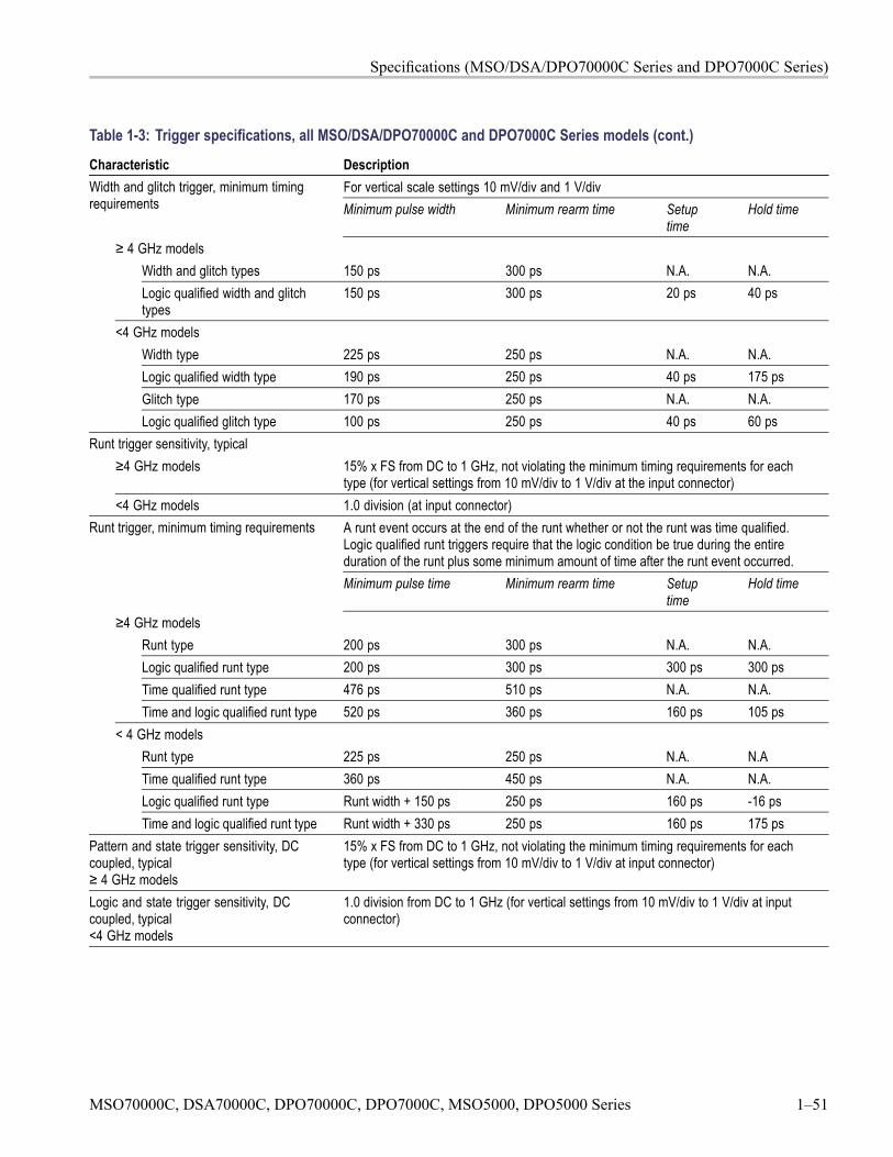
Specifications (MSO/DSA/DPO70000C Series and DPO7000C Series)
Table 1-3: Trigger specifications, all MSO/DSA/DPO70000C and DPO7000C Series models (cont.)
Characteristic DescriptionFor vertical scale settings 10 mV/div and 1 V/divWidth and glitch trigger, minimum timing
requirements Minimum pulse width Minimum rearm time Setuptime
Hold time
≥ 4 GHz modelsWidth and glitch types 150 ps 300 ps N.A. N.A.Logic qualified width and glitchtypes
150 ps 300 ps 20 ps 40 ps
<4 GHz modelsWidth type 225 ps 250 ps N.A. N.A.Logic qualified width type 190 ps 250 ps 40 ps 175 psGlitch type 170 ps 250 ps N.A. N.A.Logic qualified glitch type 100 ps 250 ps 40 ps 60 ps
Runt trigger sensitivity, typical≥4 GHz models 15% x FS from DC to 1 GHz, not violating the minimum timing requirements for each
type (for vertical settings from 10 mV/div to 1 V/div at the input connector)<4 GHz models 1.0 division (at input connector)
A runt event occurs at the end of the runt whether or not the runt was time qualified.Logic qualified runt triggers require that the logic condition be true during the entireduration of the runt plus some minimum amount of time after the runt event occurred.
Runt trigger, minimum timing requirements
Minimum pulse time Minimum rearm time Setuptime
Hold time
≥4 GHz modelsRunt type 200 ps 300 ps N.A. N.A.Logic qualified runt type 200 ps 300 ps 300 ps 300 psTime qualified runt type 476 ps 510 ps N.A. N.A.Time and logic qualified runt type 520 ps 360 ps 160 ps 105 ps
< 4 GHz modelsRunt type 225 ps 250 ps N.A. N.ATime qualified runt type 360 ps 450 ps N.A. N.A.Logic qualified runt type Runt width + 150 ps 250 ps 160 ps -16 psTime and logic qualified runt type Runt width + 330 ps 250 ps 160 ps 175 ps
Pattern and state trigger sensitivity, DCcoupled, typical≥ 4 GHz models
15% x FS from DC to 1 GHz, not violating the minimum timing requirements for eachtype (for vertical settings from 10 mV/div to 1 V/div at input connector)
Logic and state trigger sensitivity, DCcoupled, typical<4 GHz models
1.0 division from DC to 1 GHz (for vertical settings from 10 mV/div to 1 V/div at inputconnector)
MSO70000C, DSA70000C, DPO70000C, DPO7000C, MSO5000, DPO5000 Series 1–51
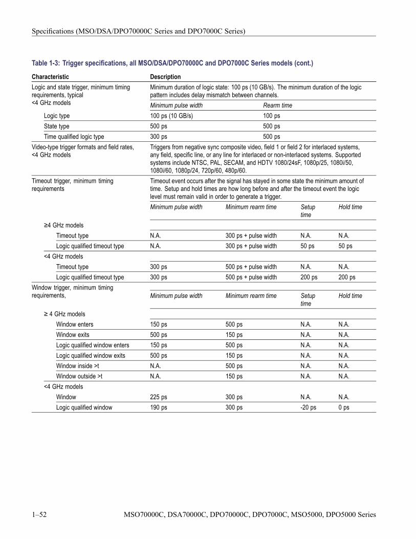
Specifications (MSO/DSA/DPO70000C Series and DPO7000C Series)
Table 1-3: Trigger specifications, all MSO/DSA/DPO70000C and DPO7000C Series models (cont.)
Characteristic DescriptionMinimum duration of logic state: 100 ps (10 GB/s). The minimum duration of the logicpattern includes delay mismatch between channels.
Logic and state trigger, minimum timingrequirements, typical<4 GHz models Minimum pulse width Rearm time
Logic type 100 ps (10 GB/s) 100 psState type 500 ps 500 psTime qualified logic type 300 ps 500 ps
Video-type trigger formats and field rates,<4 GHz models
Triggers from negative sync composite video, field 1 or field 2 for interlaced systems,any field, specific line, or any line for interlaced or non-interlaced systems. Supportedsystems include NTSC, PAL, SECAM, and HDTV 1080/24sF, 1080p/25, 1080i/50,1080i/60, 1080p/24, 720p/60, 480p/60.Timeout event occurs after the signal has stayed in some state the minimum amount oftime. Setup and hold times are how long before and after the timeout event the logiclevel must remain valid in order to generate a trigger.
Timeout trigger, minimum timingrequirements
Minimum pulse width Minimum rearm time Setuptime
Hold time
≥4 GHz modelsTimeout type N.A. 300 ps + pulse width N.A. N.A.Logic qualified timeout type N.A. 300 ps + pulse width 50 ps 50 ps
<4 GHz modelsTimeout type 300 ps 500 ps + pulse width N.A. N.A.Logic qualified timeout type 300 ps 500 ps + pulse width 200 ps 200 ps
Window trigger, minimum timingrequirements, Minimum pulse width Minimum rearm time Setup
timeHold time
≥ 4 GHz modelsWindow enters 150 ps 500 ps N.A. N.A.Window exits 500 ps 150 ps N.A. N.A.Logic qualified window enters 150 ps 500 ps N.A. N.A.Logic qualified window exits 500 ps 150 ps N.A. N.A.Window inside >t N.A. 500 ps N.A. N.A.Window outside >t N.A. 150 ps N.A. N.A.
<4 GHz modelsWindow 225 ps 300 ps N.A. N.A.Logic qualified window 190 ps 300 ps -20 ps 0 ps
1–52 MSO70000C, DSA70000C, DPO70000C, DPO7000C, MSO5000, DPO5000 Series
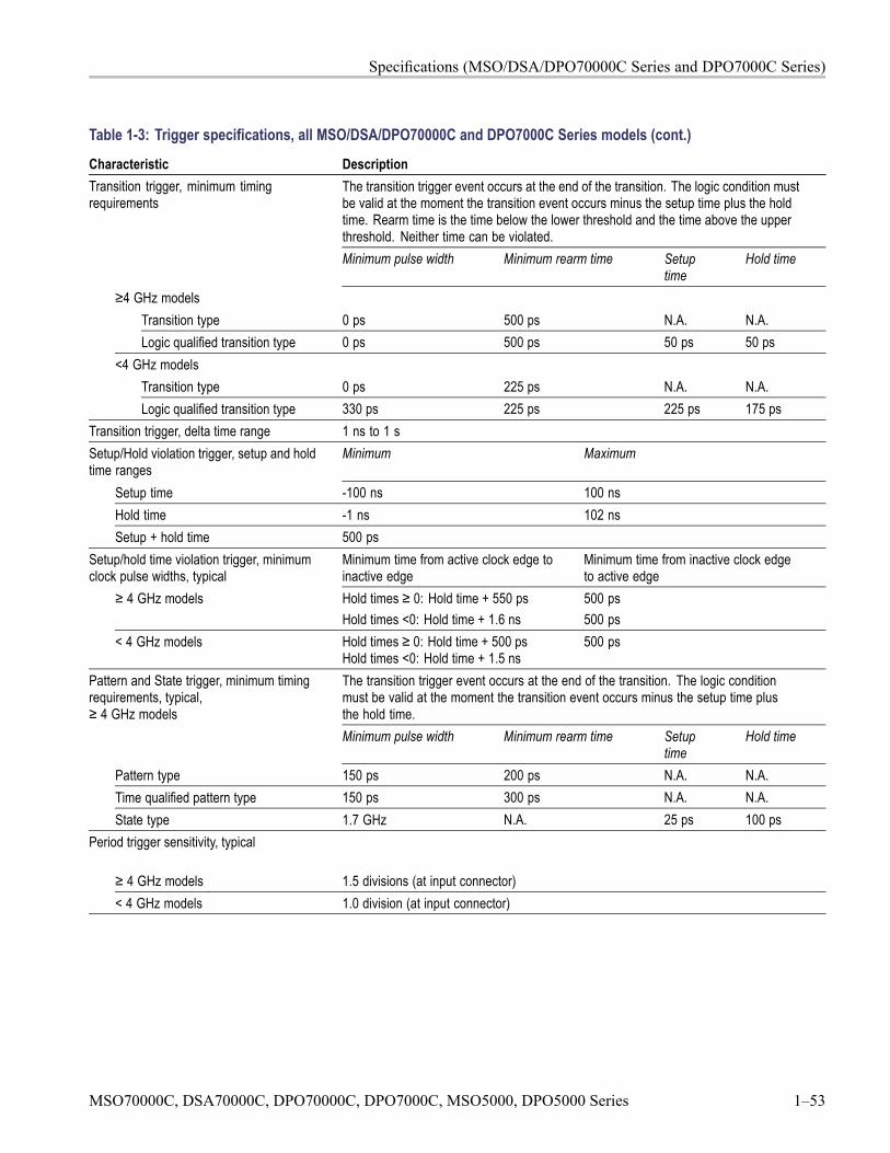
Specifications (MSO/DSA/DPO70000C Series and DPO7000C Series)
Table 1-3: Trigger specifications, all MSO/DSA/DPO70000C and DPO7000C Series models (cont.)
Characteristic DescriptionThe transition trigger event occurs at the end of the transition. The logic condition mustbe valid at the moment the transition event occurs minus the setup time plus the holdtime. Rearm time is the time below the lower threshold and the time above the upperthreshold. Neither time can be violated.
Transition trigger, minimum timingrequirements
Minimum pulse width Minimum rearm time Setuptime
Hold time
≥4 GHz modelsTransition type 0 ps 500 ps N.A. N.A.Logic qualified transition type 0 ps 500 ps 50 ps 50 ps
<4 GHz modelsTransition type 0 ps 225 ps N.A. N.A.Logic qualified transition type 330 ps 225 ps 225 ps 175 ps
Transition trigger, delta time range 1 ns to 1 sSetup/Hold violation trigger, setup and holdtime ranges
Minimum Maximum
Setup time -100 ns 100 nsHold time -1 ns 102 nsSetup + hold time 500 ps
Setup/hold time violation trigger, minimumclock pulse widths, typical
Minimum time from active clock edge toinactive edge
Minimum time from inactive clock edgeto active edge
≥ 4 GHz models Hold times ≥ 0: Hold time + 550 psHold times <0: Hold time + 1.6 ns
500 ps500 ps
< 4 GHz models Hold times ≥ 0: Hold time + 500 psHold times <0: Hold time + 1.5 ns
500 ps
The transition trigger event occurs at the end of the transition. The logic conditionmust be valid at the moment the transition event occurs minus the setup time plusthe hold time.
Pattern and State trigger, minimum timingrequirements, typical,≥ 4 GHz models
Minimum pulse width Minimum rearm time Setuptime
Hold time
Pattern type 150 ps 200 ps N.A. N.A.Time qualified pattern type 150 ps 300 ps N.A. N.A.State type 1.7 GHz N.A. 25 ps 100 ps
Period trigger sensitivity, typical
≥ 4 GHz models 1.5 divisions (at input connector)< 4 GHz models 1.0 division (at input connector)
MSO70000C, DSA70000C, DPO70000C, DPO7000C, MSO5000, DPO5000 Series 1–53
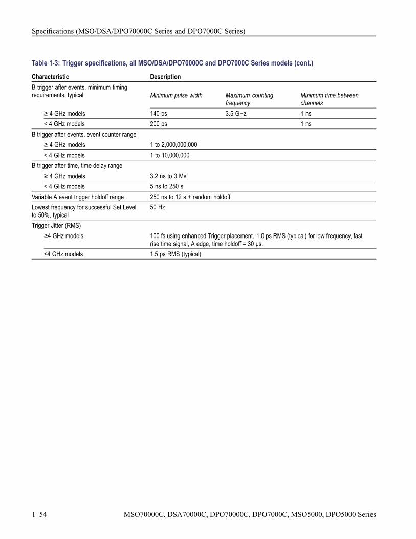
Specifications (MSO/DSA/DPO70000C Series and DPO7000C Series)
Table 1-3: Trigger specifications, all MSO/DSA/DPO70000C and DPO7000C Series models (cont.)
Characteristic DescriptionB trigger after events, minimum timingrequirements, typical Minimum pulse width Maximum counting
frequencyMinimum time betweenchannels
≥ 4 GHz models 140 ps 3.5 GHz 1 ns< 4 GHz models 200 ps 1 ns
B trigger after events, event counter range≥ 4 GHz models 1 to 2,000,000,000< 4 GHz models 1 to 10,000,000
B trigger after time, time delay range≥ 4 GHz models 3.2 ns to 3 Ms< 4 GHz models 5 ns to 250 s
Variable A event trigger holdoff range 250 ns to 12 s + random holdoffLowest frequency for successful Set Levelto 50%, typical
50 Hz
Trigger Jitter (RMS)≥4 GHz models 100 fs using enhanced Trigger placement. 1.0 ps RMS (typical) for low frequency, fast
rise time signal, A edge, time holdoff = 30 μs.<4 GHz models 1.5 ps RMS (typical)
1–54 MSO70000C, DSA70000C, DPO70000C, DPO7000C, MSO5000, DPO5000 Series
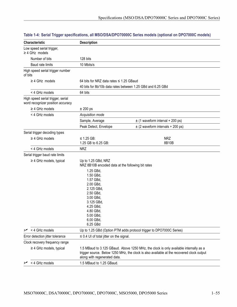
Specifications (MSO/DSA/DPO70000C Series and DPO7000C Series)
Table 1-4: Serial Trigger specifications, all MSO/DSA/DPO70000C Series models (optional on DPO7000C models)Characteristic DescriptionLow speed serial trigger,≥ 4 GHz models
Number of bits 128 bitsBaud rate limits 10 Mbits/s
High speed serial trigger numberof bits
≥ 4 GHz models 64 bits for NRZ data rates ≤ 1.25 GBaud40 bits for 8b/10b data rates between 1.25 GBd and 6.25 GBd
< 4 GHz models 64 bitsHigh speed serial trigger, serialword recognizer position accuracy
≥ 4 GHz models ± 200 psAcquisition modeSample, Average ± (1 waveform interval + 200 ps)
< 4 GHz models
Peak Detect, Envelope ± (2 waveform intervals + 200 ps)Serial trigger decoding types
≥ 4 GHz models ≤ 1.25 GB:1.25 GB to 6.25 GB:
NRZ8B10B
< 4 GHz models NRZSerial trigger baud rate limits
≥ 4 GHz models, typical Up to 1.25 GBd, NRZNRZ 8B10B encoded data at the following bit rates
1.25 GBd,1.50 GBd,1.57 GBd,2.00 GBd,2.125 GBd,2.50 GBd,3.00 GBd,3.125 GBd,4.25 GBd,4.80 GBd,5.00 GBd,6.00 GBd,6.25 GBd
< 4 GHz models Up to 1.25 GBd (Option PTM adds protocol trigger to DPO7000C Series)Error detection jitter tolerance ≤ 0.4 UI of total jitter on the signal.Clock recovery frequency range
≥ 4 GHz models, typical 1.5 MBaud to 3.125 GBaud. Above 1250 MHz, the clock is only available internally as atrigger source. Below 1250 MHz, the clock is also available at the recovered clock outputalong with regenerated data.
< 4 GHz models 1.5 MBaud to 1.25 GBaud.
MSO70000C, DSA70000C, DPO70000C, DPO7000C, MSO5000, DPO5000 Series 1–55
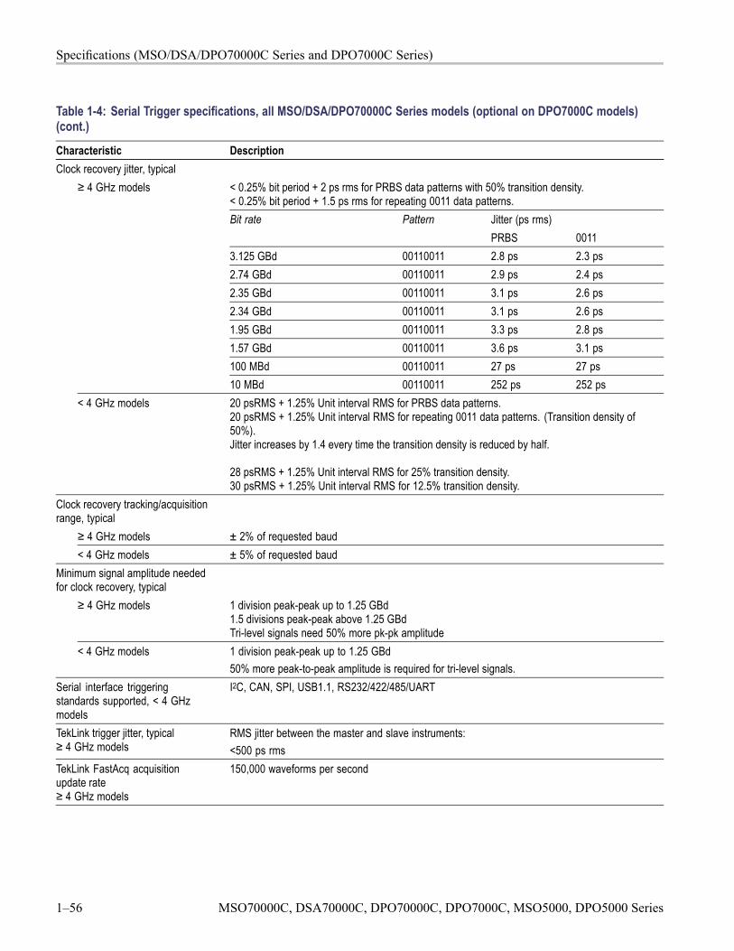
Specifications (MSO/DSA/DPO70000C Series and DPO7000C Series)
Table 1-4: Serial Trigger specifications, all MSO/DSA/DPO70000C Series models (optional on DPO7000C models)(cont.)
Characteristic DescriptionClock recovery jitter, typical
≥ 4 GHz models < 0.25% bit period + 2 ps rms for PRBS data patterns with 50% transition density.< 0.25% bit period + 1.5 ps rms for repeating 0011 data patterns.
Jitter (ps rms)Bit rate PatternPRBS 0011
3.125 GBd 00110011 2.8 ps 2.3 ps2.74 GBd 00110011 2.9 ps 2.4 ps2.35 GBd 00110011 3.1 ps 2.6 ps2.34 GBd 00110011 3.1 ps 2.6 ps1.95 GBd 00110011 3.3 ps 2.8 ps1.57 GBd 00110011 3.6 ps 3.1 ps100 MBd 00110011 27 ps 27 ps10 MBd 00110011 252 ps 252 ps
< 4 GHz models 20 psRMS + 1.25% Unit interval RMS for PRBS data patterns.20 psRMS + 1.25% Unit interval RMS for repeating 0011 data patterns. (Transition density of50%).Jitter increases by 1.4 every time the transition density is reduced by half.
28 psRMS + 1.25% Unit interval RMS for 25% transition density.30 psRMS + 1.25% Unit interval RMS for 12.5% transition density.
Clock recovery tracking/acquisitionrange, typical
≥ 4 GHz models ± 2% of requested baud< 4 GHz models ± 5% of requested baud
Minimum signal amplitude neededfor clock recovery, typical
≥ 4 GHz models 1 division peak-peak up to 1.25 GBd1.5 divisions peak-peak above 1.25 GBdTri-level signals need 50% more pk-pk amplitude
< 4 GHz models 1 division peak-peak up to 1.25 GBd50% more peak-to-peak amplitude is required for tri-level signals.
Serial interface triggeringstandards supported, < 4 GHzmodels
I2C, CAN, SPI, USB1.1, RS232/422/485/UART
TekLink trigger jitter, typical≥ 4 GHz models
RMS jitter between the master and slave instruments:<500 ps rms
TekLink FastAcq acquisitionupdate rate≥ 4 GHz models
150,000 waveforms per second
1–56 MSO70000C, DSA70000C, DPO70000C, DPO7000C, MSO5000, DPO5000 Series
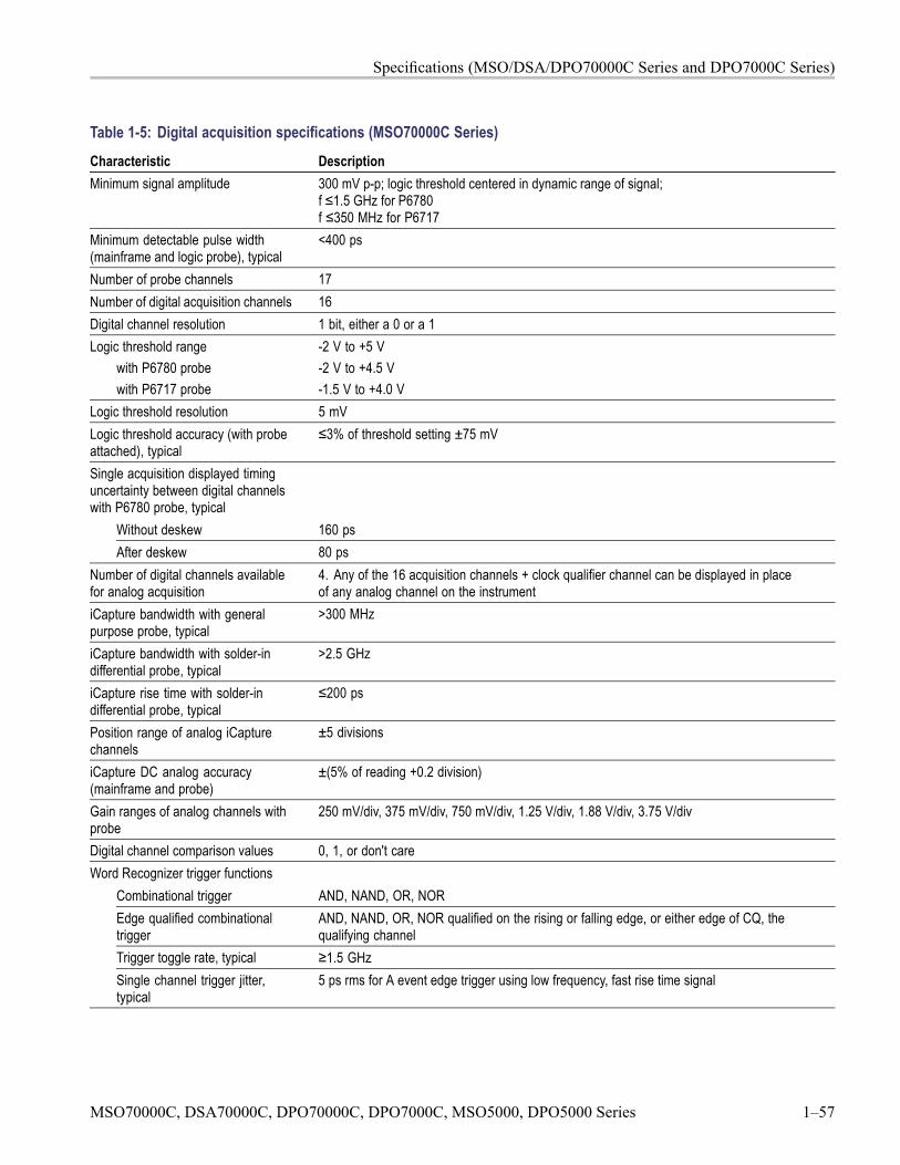
Specifications (MSO/DSA/DPO70000C Series and DPO7000C Series)
Table 1-5: Digital acquisition specifications (MSO70000C Series)Characteristic DescriptionMinimum signal amplitude 300 mV p-p; logic threshold centered in dynamic range of signal;
f ≤1.5 GHz for P6780f ≤350 MHz for P6717
Minimum detectable pulse width(mainframe and logic probe), typical
<400 ps
Number of probe channels 17Number of digital acquisition channels 16Digital channel resolution 1 bit, either a 0 or a 1Logic threshold range
with P6780 probewith P6717 probe
-2 V to +5 V-2 V to +4.5 V-1.5 V to +4.0 V
Logic threshold resolution 5 mVLogic threshold accuracy (with probeattached), typical
≤3% of threshold setting ±75 mV
Single acquisition displayed timinguncertainty between digital channelswith P6780 probe, typical
Without deskew 160 psAfter deskew 80 ps
Number of digital channels availablefor analog acquisition
4. Any of the 16 acquisition channels + clock qualifier channel can be displayed in placeof any analog channel on the instrument
iCapture bandwidth with generalpurpose probe, typical
>300 MHz
iCapture bandwidth with solder-indifferential probe, typical
>2.5 GHz
iCapture rise time with solder-indifferential probe, typical
≤200 ps
Position range of analog iCapturechannels
±5 divisions
iCapture DC analog accuracy(mainframe and probe)
±(5% of reading +0.2 division)
Gain ranges of analog channels withprobe
250 mV/div, 375 mV/div, 750 mV/div, 1.25 V/div, 1.88 V/div, 3.75 V/div
Digital channel comparison values 0, 1, or don't careWord Recognizer trigger functions
Combinational trigger AND, NAND, OR, NOREdge qualified combinationaltrigger
AND, NAND, OR, NOR qualified on the rising or falling edge, or either edge of CQ, thequalifying channel
Trigger toggle rate, typical ≥1.5 GHzSingle channel trigger jitter,typical
5 ps rms for A event edge trigger using low frequency, fast rise time signal
MSO70000C, DSA70000C, DPO70000C, DPO7000C, MSO5000, DPO5000 Series 1–57
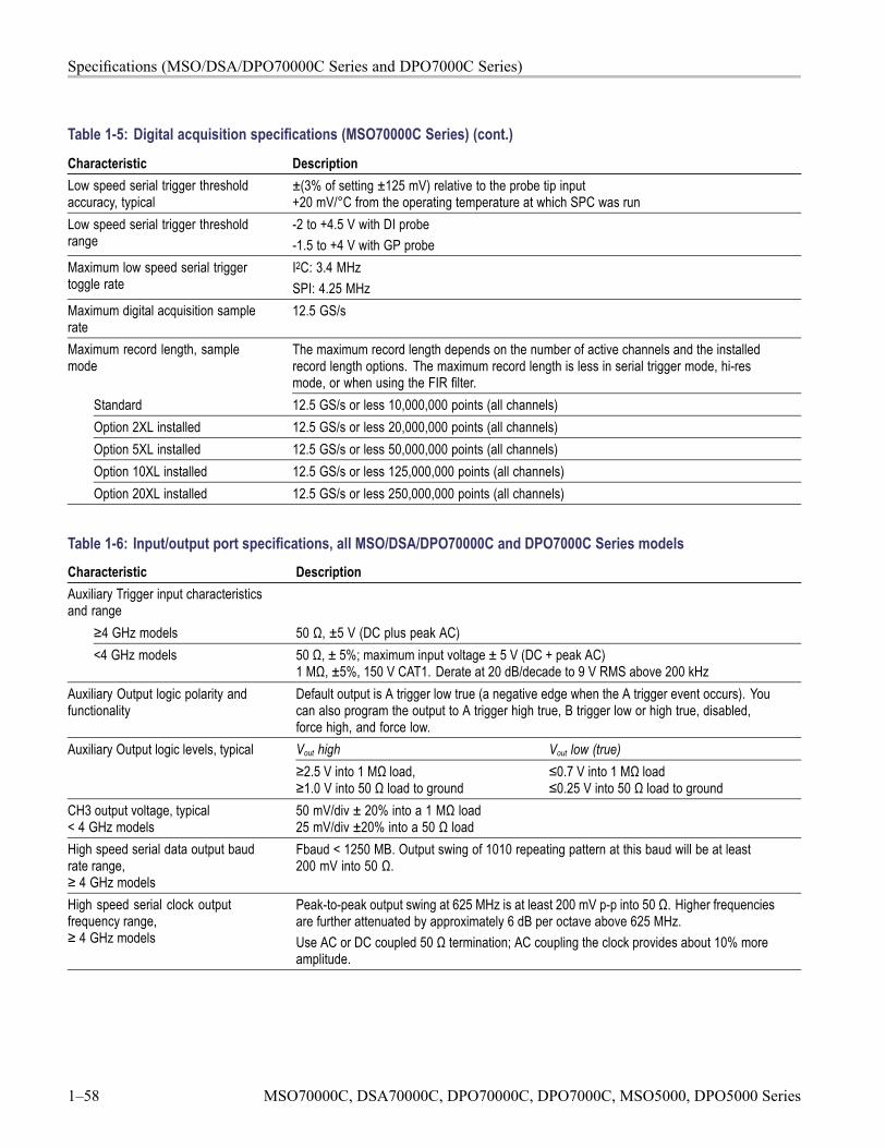
Specifications (MSO/DSA/DPO70000C Series and DPO7000C Series)
Table 1-5: Digital acquisition specifications (MSO70000C Series) (cont.)
Characteristic DescriptionLow speed serial trigger thresholdaccuracy, typical
±(3% of setting ±125 mV) relative to the probe tip input+20 mV/°C from the operating temperature at which SPC was run
Low speed serial trigger thresholdrange
-2 to +4.5 V with DI probe-1.5 to +4 V with GP probe
Maximum low speed serial triggertoggle rate
I2C: 3.4 MHzSPI: 4.25 MHz
Maximum digital acquisition samplerate
12.5 GS/s
Maximum record length, samplemode
The maximum record length depends on the number of active channels and the installedrecord length options. The maximum record length is less in serial trigger mode, hi-resmode, or when using the FIR filter.
Standard 12.5 GS/s or less 10,000,000 points (all channels)Option 2XL installed 12.5 GS/s or less 20,000,000 points (all channels)Option 5XL installed 12.5 GS/s or less 50,000,000 points (all channels)Option 10XL installed 12.5 GS/s or less 125,000,000 points (all channels)Option 20XL installed 12.5 GS/s or less 250,000,000 points (all channels)
Table 1-6: Input/output port specifications, all MSO/DSA/DPO70000C and DPO7000C Series modelsCharacteristic DescriptionAuxiliary Trigger input characteristicsand range
≥4 GHz models 50 Ω, ±5 V (DC plus peak AC)<4 GHz models 50 Ω, ± 5%; maximum input voltage ± 5 V (DC + peak AC)
1 MΩ, ±5%, 150 V CAT1. Derate at 20 dB/decade to 9 V RMS above 200 kHzAuxiliary Output logic polarity andfunctionality
Default output is A trigger low true (a negative edge when the A trigger event occurs). Youcan also program the output to A trigger high true, B trigger low or high true, disabled,force high, and force low.Vout high Vout low (true)Auxiliary Output logic levels, typical≥2.5 V into 1 MΩ load,≥1.0 V into 50 Ω load to ground
≤0.7 V into 1 MΩ load≤0.25 V into 50 Ω load to ground
CH3 output voltage, typical< 4 GHz models
50 mV/div ± 20% into a 1 MΩ load25 mV/div ±20% into a 50 Ω load
High speed serial data output baudrate range,≥ 4 GHz models
Fbaud < 1250 MB. Output swing of 1010 repeating pattern at this baud will be at least200 mV into 50 Ω.
High speed serial clock outputfrequency range,≥ 4 GHz models
Peak-to-peak output swing at 625 MHz is at least 200 mV p-p into 50 Ω. Higher frequenciesare further attenuated by approximately 6 dB per octave above 625 MHz.Use AC or DC coupled 50 Ω termination; AC coupling the clock provides about 10% moreamplitude.
1–58 MSO70000C, DSA70000C, DPO70000C, DPO7000C, MSO5000, DPO5000 Series
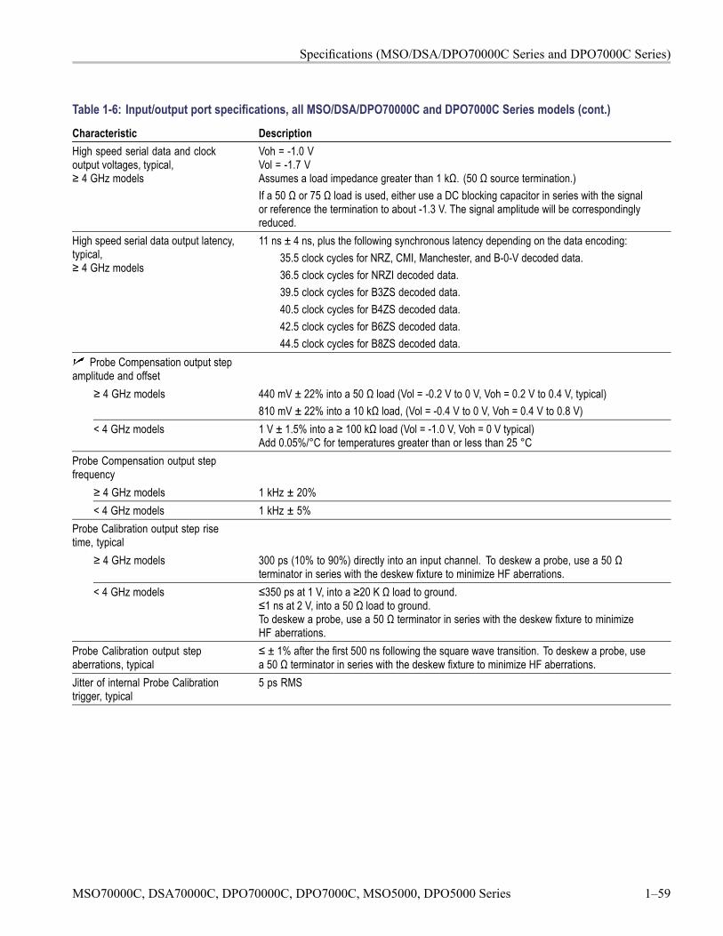
Specifications (MSO/DSA/DPO70000C Series and DPO7000C Series)
Table 1-6: Input/output port specifications, all MSO/DSA/DPO70000C and DPO7000C Series models (cont.)
Characteristic DescriptionHigh speed serial data and clockoutput voltages, typical,≥ 4 GHz models
Voh = -1.0 VVol = -1.7 VAssumes a load impedance greater than 1 kΩ. (50 Ω source termination.)If a 50 Ω or 75 Ω load is used, either use a DC blocking capacitor in series with the signalor reference the termination to about -1.3 V. The signal amplitude will be correspondinglyreduced.
High speed serial data output latency,typical,≥ 4 GHz models
11 ns ± 4 ns, plus the following synchronous latency depending on the data encoding:35.5 clock cycles for NRZ, CMI, Manchester, and B-0-V decoded data.36.5 clock cycles for NRZI decoded data.39.5 clock cycles for B3ZS decoded data.40.5 clock cycles for B4ZS decoded data.42.5 clock cycles for B6ZS decoded data.44.5 clock cycles for B8ZS decoded data.
Probe Compensation output stepamplitude and offset
≥ 4 GHz models 440 mV ± 22% into a 50 Ω load (Vol = -0.2 V to 0 V, Voh = 0.2 V to 0.4 V, typical)810 mV ± 22% into a 10 kΩ load, (Vol = -0.4 V to 0 V, Voh = 0.4 V to 0.8 V)
< 4 GHz models 1 V ± 1.5% into a ≥ 100 kΩ load (Vol = -1.0 V, Voh = 0 V typical)Add 0.05%/°C for temperatures greater than or less than 25 °C
Probe Compensation output stepfrequency
≥ 4 GHz models 1 kHz ± 20%< 4 GHz models 1 kHz ± 5%
Probe Calibration output step risetime, typical
≥ 4 GHz models 300 ps (10% to 90%) directly into an input channel. To deskew a probe, use a 50 Ωterminator in series with the deskew fixture to minimize HF aberrations.
< 4 GHz models ≤350 ps at 1 V, into a ≥20 K Ω load to ground.≤1 ns at 2 V, into a 50 Ω load to ground.To deskew a probe, use a 50 Ω terminator in series with the deskew fixture to minimizeHF aberrations.
Probe Calibration output stepaberrations, typical
≤ ± 1% after the first 500 ns following the square wave transition. To deskew a probe, usea 50 Ω terminator in series with the deskew fixture to minimize HF aberrations.
Jitter of internal Probe Calibrationtrigger, typical
5 ps RMS
MSO70000C, DSA70000C, DPO70000C, DPO7000C, MSO5000, DPO5000 Series 1–59
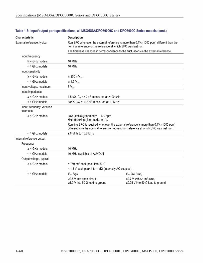
Specifications (MSO/DSA/DPO70000C Series and DPO7000C Series)
Table 1-6: Input/output port specifications, all MSO/DSA/DPO70000C and DPO7000C Series models (cont.)
Characteristic DescriptionExternal reference, typical Run SPC whenever the external reference is more than 0.1% (1000 ppm) different than the
nominal reference or the reference at which SPC was last run.The timebase changes in correspondence to the fluctuations in the external reference.
Input frequency≥ 4 GHz models 10 MHz< 4 GHz models 10 MHz
Input sensitivity≥ 4 GHz models ≥ 200 mVp-p
< 4 GHz models ≥ 1.5 Vp-p
Input voltage, maximum 7 Vp-p
Input impedance≥ 4 GHz models 1.5 kΩ, Cin = 40 pF, measured at >100 kHz< 4 GHz models 385 Ω, Cin = 137 pF, measured at 10 MHz
Input frequency variationtolerance
≥ 4 GHz models Low (stable) jitter mode: ± 100 ppmHigh (tracking) jitter mode: ± 1%Running SPC is required whenever the external reference is more than 0.1% (1000 ppm)different from the nominal reference frequency or reference at which SPC was last run.
< 4 GHz models 9.8 MHz to 10.2 MHzInternal reference output
Frequency≥ 4 GHz models 10 MHz< 4 GHz models 10 MHz available at AUXOUT
Output voltage, typical≥ 4 GHz models > 750 mV peak-peak into 50 Ω
> 1.5 V peak-peak into 1 MΩ (internally AC coupled).Vout high Vout low (true)< 4 GHz models≥2.5 V into open circuit,≥1.0 V into 50 Ω load to ground
≤0.7 V with ≤4 mA sink,≤0.25 V into 50 Ω load to ground
1–60 MSO70000C, DSA70000C, DPO70000C, DPO7000C, MSO5000, DPO5000 Series
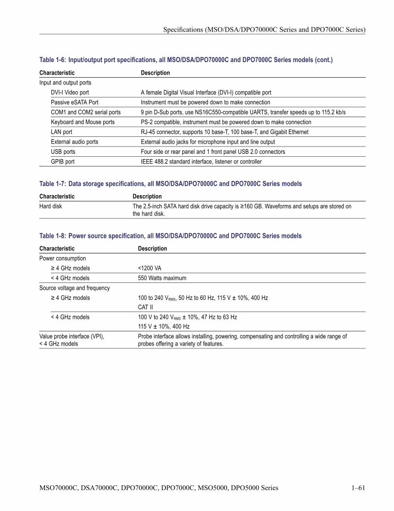
Specifications (MSO/DSA/DPO70000C Series and DPO7000C Series)
Table 1-6: Input/output port specifications, all MSO/DSA/DPO70000C and DPO7000C Series models (cont.)
Characteristic DescriptionInput and output ports
DVI-I Video port A female Digital Visual Interface (DVI-I) compatible portPassive eSATA Port Instrument must be powered down to make connectionCOM1 and COM2 serial ports 9 pin D-Sub ports, use NS16C550-compatible UARTS, transfer speeds up to 115.2 kb/sKeyboard and Mouse ports PS-2 compatible, instrument must be powered down to make connectionLAN port RJ-45 connector, supports 10 base-T, 100 base-T, and Gigabit EthernetExternal audio ports External audio jacks for microphone input and line outputUSB ports Four side or rear panel and 1 front panel USB 2.0 connectorsGPIB port IEEE 488.2 standard interface, listener or controller
Table 1-7: Data storage specifications, all MSO/DSA/DPO70000C and DPO7000C Series modelsCharacteristic DescriptionHard disk The 2.5-inch SATA hard disk drive capacity is ≥160 GB. Waveforms and setups are stored on
the hard disk.
Table 1-8: Power source specification, all MSO/DSA/DPO70000C and DPO7000C Series modelsCharacteristic DescriptionPower consumption
≥ 4 GHz models <1200 VA< 4 GHz models 550 Watts maximum
Source voltage and frequency≥ 4 GHz models 100 to 240 VRMS, 50 Hz to 60 Hz, 115 V ± 10%, 400 Hz
CAT II< 4 GHz models 100 V to 240 VRMS ± 10%, 47 Hz to 63 Hz
115 V ± 10%, 400 HzValue probe interface (VPI),< 4 GHz models
Probe interface allows installing, powering, compensating and controlling a wide range ofprobes offering a variety of features.
MSO70000C, DSA70000C, DPO70000C, DPO7000C, MSO5000, DPO5000 Series 1–61
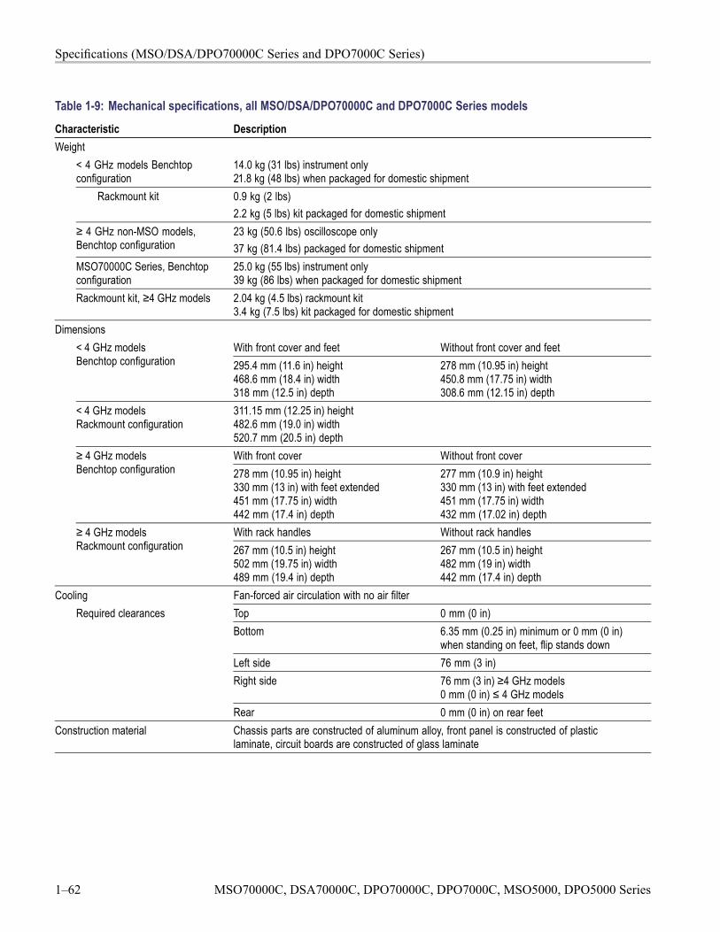
Specifications (MSO/DSA/DPO70000C Series and DPO7000C Series)
Table 1-9: Mechanical specifications, all MSO/DSA/DPO70000C and DPO7000C Series modelsCharacteristic DescriptionWeight
< 4 GHz models Benchtopconfiguration
14.0 kg (31 lbs) instrument only21.8 kg (48 lbs) when packaged for domestic shipment
Rackmount kit 0.9 kg (2 lbs)2.2 kg (5 lbs) kit packaged for domestic shipment
≥ 4 GHz non-MSO models,Benchtop configuration
23 kg (50.6 lbs) oscilloscope only37 kg (81.4 lbs) packaged for domestic shipment
MSO70000C Series, Benchtopconfiguration
25.0 kg (55 lbs) instrument only39 kg (86 lbs) when packaged for domestic shipment
Rackmount kit, ≥4 GHz models 2.04 kg (4.5 lbs) rackmount kit3.4 kg (7.5 lbs) kit packaged for domestic shipment
DimensionsWith front cover and feet Without front cover and feet< 4 GHz models
Benchtop configuration 295.4 mm (11.6 in) height468.6 mm (18.4 in) width318 mm (12.5 in) depth
278 mm (10.95 in) height450.8 mm (17.75 in) width308.6 mm (12.15 in) depth
< 4 GHz modelsRackmount configuration
311.15 mm (12.25 in) height482.6 mm (19.0 in) width520.7 mm (20.5 in) depthWith front cover Without front cover≥ 4 GHz models
Benchtop configuration 278 mm (10.95 in) height330 mm (13 in) with feet extended451 mm (17.75 in) width442 mm (17.4 in) depth
277 mm (10.9 in) height330 mm (13 in) with feet extended451 mm (17.75 in) width432 mm (17.02 in) depth
With rack handles Without rack handles≥ 4 GHz modelsRackmount configuration 267 mm (10.5 in) height
502 mm (19.75 in) width489 mm (19.4 in) depth
267 mm (10.5 in) height482 mm (19 in) width442 mm (17.4 in) depth
Cooling Fan-forced air circulation with no air filterTop 0 mm (0 in)Bottom 6.35 mm (0.25 in) minimum or 0 mm (0 in)
when standing on feet, flip stands downLeft side 76 mm (3 in)Right side 76 mm (3 in) ≥4 GHz models
0 mm (0 in) ≤ 4 GHz models
Required clearances
Rear 0 mm (0 in) on rear feetConstruction material Chassis parts are constructed of aluminum alloy, front panel is constructed of plastic
laminate, circuit boards are constructed of glass laminate
1–62 MSO70000C, DSA70000C, DPO70000C, DPO7000C, MSO5000, DPO5000 Series
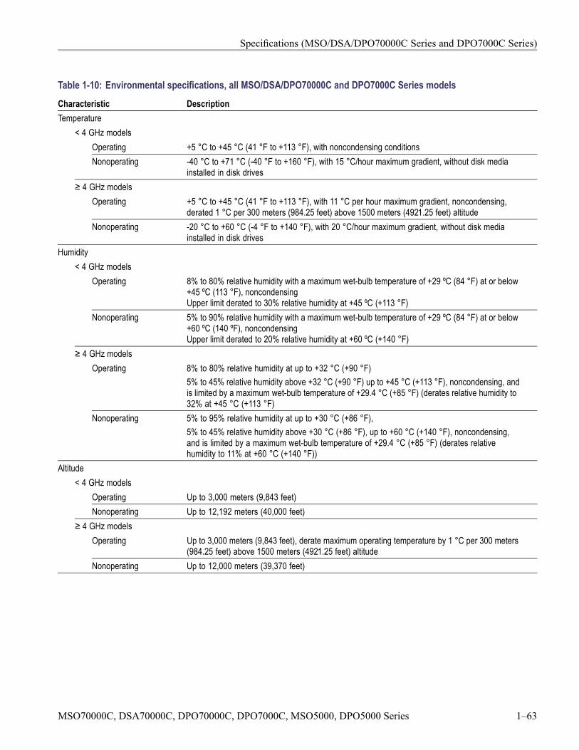
Specifications (MSO/DSA/DPO70000C Series and DPO7000C Series)
Table 1-10: Environmental specifications, all MSO/DSA/DPO70000C and DPO7000C Series modelsCharacteristic DescriptionTemperature
< 4 GHz modelsOperating +5 °C to +45 °C (41 °F to +113 °F), with noncondensing conditionsNonoperating -40 °C to +71 °C (-40 °F to +160 °F), with 15 °C/hour maximum gradient, without disk media
installed in disk drives≥ 4 GHz models
Operating +5 °C to +45 °C (41 °F to +113 °F), with 11 °C per hour maximum gradient, noncondensing,derated 1 °C per 300 meters (984.25 feet) above 1500 meters (4921.25 feet) altitude
Nonoperating -20 °C to +60 °C (-4 °F to +140 °F), with 20 °C/hour maximum gradient, without disk mediainstalled in disk drives
Humidity< 4 GHz models
Operating 8% to 80% relative humidity with a maximum wet-bulb temperature of +29 ºC (84 °F) at or below+45 ºC (113 °F), noncondensingUpper limit derated to 30% relative humidity at +45 ºC (+113 °F)
Nonoperating 5% to 90% relative humidity with a maximum wet-bulb temperature of +29 ºC (84 °F) at or below+60 ºC (140 ºF), noncondensingUpper limit derated to 20% relative humidity at +60 ºC (+140 °F)
≥ 4 GHz modelsOperating 8% to 80% relative humidity at up to +32 °C (+90 °F)
5% to 45% relative humidity above +32 °C (+90 °F) up to +45 °C (+113 °F), noncondensing, andis limited by a maximum wet-bulb temperature of +29.4 °C (+85 °F) (derates relative humidity to32% at +45 °C (+113 °F)
Nonoperating 5% to 95% relative humidity at up to +30 °C (+86 °F),5% to 45% relative humidity above +30 °C (+86 °F), up to +60 °C (+140 °F), noncondensing,and is limited by a maximum wet-bulb temperature of +29.4 °C (+85 °F) (derates relativehumidity to 11% at +60 °C (+140 °F))
Altitude< 4 GHz models
Operating Up to 3,000 meters (9,843 feet)Nonoperating Up to 12,192 meters (40,000 feet)
≥ 4 GHz modelsOperating Up to 3,000 meters (9,843 feet), derate maximum operating temperature by 1 °C per 300 meters
(984.25 feet) above 1500 meters (4921.25 feet) altitudeNonoperating Up to 12,000 meters (39,370 feet)
MSO70000C, DSA70000C, DPO70000C, DPO7000C, MSO5000, DPO5000 Series 1–63

Specifications (MSO/DSA/DPO70000C Series and DPO7000C Series)
1–64 MSO70000C, DSA70000C, DPO70000C, DPO7000C, MSO5000, DPO5000 Series

Specifications (MSO/DPO5000 Series)

Specifications (MSO/DPO5000 Series)This chapter contains specifications for the MSO5000 and DPO5000 seriesoscilloscopes. All specifications are guaranteed unless noted as "typical."Typical specifications are provided for your convenience but are not guaranteed.Specifications that are marked with the symbol are checked in PerformanceVerification.
All specifications apply to all MSO5000 and DPO5000 models unless notedotherwise. To meet specifications, two conditions must first be met:
The oscilloscope must have been operating continuously for twenty minuteswithin the operating temperature range specified.
You must perform the Signal Path Compensation (SPC) operation beforeevaluating the instrument's performance to the specifications. (See page 4-26,Self Test.) If the operating temperature changes by more than 10 °C (18 °F),perform the SPC operation again.
Table 2-1: Analog channel input and vertical specificationCharacteristic DescriptionNumber of inputchannels
4 analog channels, digitized simultaneously
Input coupling DC or ACInput resistanceselection
1 MΩ or 50 Ω250 kΩ selectable for performance verification.1 MΩ 1 MΩ ±1%
50 Ω ±1%MSO5204,DPO5204
VSWR ≤1.5:1 from DC to 2 GHz, typical
MSO5104,DPO5104
VSWR ≤1.5:1 from DC to 1 GHz, typical
MSO5054,DPO5054
VSWR ≤1.5:1 from DC to 500 MHz, typical
Inputimpedance, DCcoupled
50 Ω
MSO5034,DPO5034
VSWR ≤1.5:1 from DC to 350 MHz, typical
InputCapacitance,1 MΩ DC coupled
13 pF ± 2 pF
MSO70000C, DSA70000C, DPO70000C, DPO7000C, MSO5000, DPO5000 Series 2–1
Specifications (MSO/DPO5000 Series)
Table 2-1: Analog channel input and vertical specification (cont.)
Characteristic Description1 MΩ 300 VRMS with peaks ≤±425 V at the BNC
Installation Category IIFor <100 mV/div, derate at 20 dB/decade above 100 kHz to 30 VRMS at 1 MHz,10 dB/decade above 1 MHzFor ≥100 mV/div, derate at 20 dB/decade above 3 MHz to 30 VRMS at 30 MHz,10 dB/decade above 30 MHz
Maximum inputvoltage
50 Ω 5 VRMS with peaks ≤±20 V (DF ≤ 6.25%)Overvoltage trip is intended to protect against overloads that might damage terminationresistors. A sufficiently large impulse might cause damage regardless of the overvoltageprotection circuitry because of the finite time required to detect and respond.
DC Balance 0.1 div with the input DC 50 Ω coupled and 50 Ω terminated0.2 div at 1 mV/div with the input DC 50 Ω coupled and 50 Ω terminated0.2 div with the input DC 1 MΩ coupled and 50 Ω terminated
Number ofdigitized bits
8 bitsDisplayed vertically with 25 digitization levels (DL) per division, 10.24 divisions dynamic range."DL" is the abbreviation for "digitization level." A DL is the smallest voltage level change that can be resolved byan 8-bit A-D Converter. This value is also known as the LSB (least significant bit).1 MΩ 1 mV/div to 10 V/div in a 1-2-5 sequenceSensitivity range
(coarse) 50 Ω 1 mV/div to 1 V/div in a 1-2-5 sequence1 mV/div to 5 V/div <–50% to >+50% of selected setting1 MΩ10 V/div <–50% to 0%1 mV/div to 500 mV/div <–50% to >+50% of selected setting1 V/div <–50% to 0%
Sensitivity range(fine)
50 Ω
Allows continuous adjustment from1 mV/div to 10 V/div
Allows continuous adjustment from1 mV/div to 1 V/div
Sensitivityresolution (fine),typical
≤1% of current setting
DC gainaccuracy
For 50 Ω, 1 MΩ, TPP0500, and TPP1000 path:±1.5%, derated at 0.100%/°C above 30 °C±2.0%, derated at 0.100%/°C above 30 °C, 1 mV/Div setting±3.0% variable gain, derated at 0.100%/°C above 30 °C
2–2 MSO70000C, DSA70000C, DPO70000C, DPO7000C, MSO5000, DPO5000 Series
Specifications (MSO/DPO5000 Series)
Table 2-1: Analog channel input and vertical specification (cont.)
Characteristic DescriptionOffset rangeVolts/div setting1 MΩ input 50 Ω input
1 mV/div to 50 mV/div ±1 V ±1 V50.5 mV/div to 99.5 mV/div ±0.5 V ±0.5 V100 mV/div to 500 mV/div ±10 V ±10 V505 mV/div to 995 mV/div ±5 V ±5 V1 V/div to 5 V/div ±100 V ±5 V5.05 V/div to 10 V/div ±50 V Not applicable
Offset ranges,minimum
For 50 Ω path, 1 V/div is the maximum vertical setting.The input signal cannot exceed Max Input Voltage for the 50 Ω input path. Refer to the Max Input Voltagespecification for more information.
Position range ±5 divisionsOffset
accuracy±[0.005 × | offset - position | + DC Balance]Both the position and constant offset term must be converted to volts by multiplying by the appropriate volts/divterm.
Number ofWaveformsfor AverageAcquisition Mode
2 to 10,000 waveformsDefault of 16 waveforms
Average of ≥ 16 waveforms ±[DC Gain Accuracy × | reading – (offset - position) | + offsetaccuracy + 0.1 division ]Refer to DC Gain Accuracy for temperature derating information.
Delta Volts between any two averagesof ≥16 waveforms acquired with thesame oscilloscope setup and ambientconditions
±[DC gain accuracy × | reading | + 0.05 div]Refer to DC Gain Accuracy for temperature derating information.
DC voltagemeasurementaccuracy
Averageacquisitionmode
Note: Offset, position, and the constant offset term must be converted to volts by multiplying by the appropriatevolts/div term.The basic accuracy specification applies directly to any sample and to the following measurements: High, Low,Max, Min, Mean, Cycle Mean, RMS, and Cycle RMS. The delta volt accuracy specification applies to subtractivecalculations involving two of these measurements.The delta volts (difference voltage) accuracy specification applies directly to the following measurements:Positive Overshoot, Negative Overshoot, Peak-to-Peak, and Amplitude.
MSO70000C, DSA70000C, DPO70000C, DPO7000C, MSO5000, DPO5000 Series 2–3
Specifications (MSO/DPO5000 Series)
Table 2-1: Analog channel input and vertical specification (cont.)
Characteristic DescriptionMeasurement type DC Accuracy (in volts)Any sample ±[DC gain accuracy × | reading - (offset - position) | + offset
accuracy +0.15 div + 0.6 mV]Refer to DC Gain Accuracy for temperature derating information.
Delta volts between any two samplesacquired with the same oscilloscopesetup and ambient conditions
±[DC gain accuracy × | reading | + 0.15 div + 1.2 mV]Refer to DC Gain Accuracy for temperature derating information.
Sampleacquisitionmode,typical
Offset, position, and the constant offset term must be converted to volts by multiplying by the appropriatevolts/div term.
Analogbandwidthselections
20 MHz, 250 MHz, and Full
Full bandwidth, with amplitude tolerance of -3 dB and operating temperatures of ≤30 °C (86 °F).Reduce the bandwidth by 1% for each °C above 30 °C.Instrument SCALE range Bandwidth
10 mV/div — 1 V/div DC to 2.00 GHz5 mV/div — 9.98 mV/div DC to 1.50 GHz2 mV/div — 4.98 mV/div DC to 350 MHz
MSO5204,DPO5204
1 mV/div — 1.99 mV/div DC to 175 MHz5 mV/div — 1 V/div DC to 1.00 GHz2 mV/div — 4.98 mV/div DC to 350 MHz
MSO5104,DPO5104
1 mV/div — 1.99 mV/div DC to 175 MHz5 mV/div — 1 V/div DC to 500 MHz2 mV/div — 4.98 mV/div DC to 350 MHz
MSO5054,DPO5054
1 mV/div — 1.99 mV/div DC to 175 MHz2 mV/div — 1 V/div DC to 350 MHz
Analogbandwidth, 50 Ω,DC coupled
MSO5034,DPO5034 1 mV/div — 1.99 mV/div DC to 175 MHz
2–4 MSO70000C, DSA70000C, DPO70000C, DPO7000C, MSO5000, DPO5000 Series
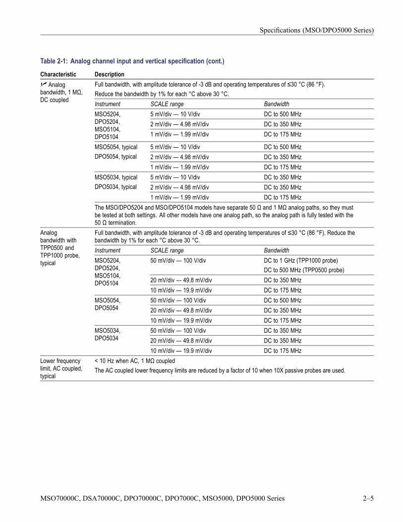
Specifications (MSO/DPO5000 Series)
Table 2-1: Analog channel input and vertical specification (cont.)
Characteristic DescriptionFull bandwidth, with amplitude tolerance of -3 dB and operating temperatures of ≤30 °C (86 °F).Reduce the bandwidth by 1% for each °C above 30 °C.Instrument SCALE range Bandwidth
5 mV/div — 10 V/div DC to 500 MHz2 mV/div — 4.98 mV/div DC to 350 MHz
MSO5204,DPO5204,MSO5104,DPO5104 1 mV/div — 1.99 mV/div DC to 175 MHz
5 mV/div — 10 V/div DC to 500 MHz2 mV/div — 4.98 mV/div DC to 350 MHz
MSO5054, typicalDPO5054, typical
1 mV/div — 1.99 mV/div DC to 175 MHz5 mV/div — 10 V/div DC to 350 MHz2 mV/div — 4.98 mV/div DC to 350 MHz
MSO5034, typicalDPO5034, typical
1 mV/div — 1.99 mV/div DC to 175 MHz
Analogbandwidth, 1 MΩ,DC coupled
The MSO/DPO5204 and MSO/DPO5104 models have separate 50 Ω and 1 MΩ analog paths, so they mustbe tested at both settings. All other models have one analog path, so the analog path is fully tested with the50 Ω termination.Full bandwidth, with amplitude tolerance of -3 dB and operating temperatures of ≤30 °C (86 °F). Reduce thebandwidth by 1% for each °C above 30 °C.Instrument SCALE range Bandwidth
50 mV/div — 100 V/div DC to 1 GHz (TPP1000 probe)DC to 500 MHz (TPP0500 probe)
20 mV/div — 49.8 mV/div DC to 350 MHz
MSO5204,DPO5204,MSO5104,DPO5104
10 mV/div — 19.9 mV/div DC to 175 MHz50 mV/div — 100 V/div DC to 500 MHz20 mV/div — 49.8 mV/div DC to 350 MHz
MSO5054,DPO5054
10 mV/div — 19.9 mV/div DC to 175 MHz50 mV/div — 100 V/div DC to 350 MHz20 mV/div — 49.8 mV/div DC to 350 MHz
Analogbandwidth withTPP0500 andTPP1000 probe,typical
MSO5034,DPO5034
10 mV/div — 19.9 mV/div DC to 175 MHzLower frequencylimit, AC coupled,typical
< 10 Hz when AC, 1 MΩ coupledThe AC coupled lower frequency limits are reduced by a factor of 10 when 10X passive probes are used.
MSO70000C, DSA70000C, DPO70000C, DPO7000C, MSO5000, DPO5000 Series 2–5
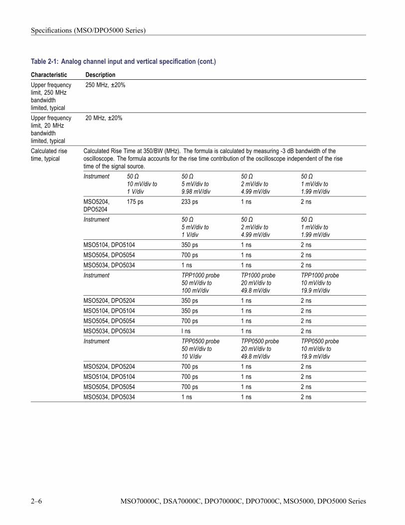
Specifications (MSO/DPO5000 Series)
Table 2-1: Analog channel input and vertical specification (cont.)
Characteristic DescriptionUpper frequencylimit, 250 MHzbandwidthlimited, typical
250 MHz, ±20%
Upper frequencylimit, 20 MHzbandwidthlimited, typical
20 MHz, ±20%
Calculated Rise Time at 350/BW (MHz). The formula is calculated by measuring -3 dB bandwidth of theoscilloscope. The formula accounts for the rise time contribution of the oscilloscope independent of the risetime of the signal source.Instrument 50 Ω
10 mV/div to1 V/div
50 Ω5 mV/div to9.98 mV/div
50 Ω2 mV/div to4.99 mV/div
50 Ω1 mV/div to1.99 mV/div
MSO5204,DPO5204
175 ps 233 ps 1 ns 2 ns
Instrument 50 Ω5 mV/div to1 V/div
50 Ω2 mV/div to4.99 mV/div
50 Ω1 mV/div to1.99 mV/div
MSO5104, DPO5104 350 ps 1 ns 2 nsMSO5054, DPO5054 700 ps 1 ns 2 nsMSO5034, DPO5034 1 ns 1 ns 2 nsInstrument TPP1000 probe
50 mV/div to100 mV/div
TP1000 probe20 mV/div to49.8 mV/div
TPP1000 probe10 mV/div to19.9 mV/div
MSO5204, DPO5204 350 ps 1 ns 2 nsMSO5104, DPO5104 350 ps 1 ns 2 nsMSO5054, DPO5054 700 ps 1 ns 2 nsMSO5034, DPO5034 I ns 1 ns 2 nsInstrument TPP0500 probe
50 mV/div to10 V/div
TPP0500 probe20 mV/div to49.8 mV/div
TPP0500 probe10 mV/div to19.9 mV/div
MSO5204, DPO5204 700 ps 1 ns 2 nsMSO5104, DPO5104 700 ps 1 ns 2 nsMSO5054, DPO5054 700 ps 1 ns 2 ns
Calculated risetime, typical
MSO5034, DPO5034 1 ns 1 ns 2 ns
2–6 MSO70000C, DSA70000C, DPO70000C, DPO7000C, MSO5000, DPO5000 Series
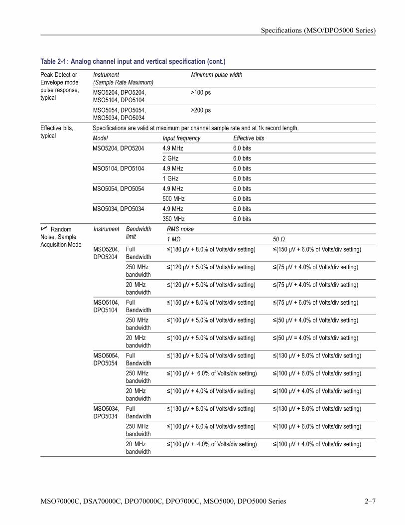
Specifications (MSO/DPO5000 Series)
Table 2-1: Analog channel input and vertical specification (cont.)
Instrument(Sample Rate Maximum)
Minimum pulse width
MSO5204, DPO5204,MSO5104, DPO5104
>100 ps
Peak Detect orEnvelope modepulse response,typical
MSO5054, DPO5054,MSO5034, DPO5034
>200 ps
Specifications are valid at maximum per channel sample rate and at 1k record length.Model Input frequency Effective bits
4.9 MHz 6.0 bitsMSO5204, DPO52042 GHz 6.0 bits4.9 MHz 6.0 bitsMSO5104, DPO51041 GHz 6.0 bits4.9 MHz 6.0 bitsMSO5054, DPO5054500 MHz 6.0 bits4.9 MHz 6.0 bits
Effective bits,typical
MSO5034, DPO5034350 MHz 6.0 bits
RMS noiseInstrument Bandwidthlimit 1 MΩ 50 ΩFullBandwidth
≤(180 μV + 8.0% of Volts/div setting) ≤(150 μV + 6.0% of Volts/div setting)
250 MHzbandwidth
≤(120 μV + 5.0% of Volts/div setting) ≤(75 μV + 4.0% of Volts/div setting)
MSO5204,DPO5204
20 MHzbandwidth
≤(120 μV + 5.0% of Volts/div setting) ≤(75 μV + 4.0% of Volts/div setting)
FullBandwidth
≤(150 μV + 8.0% of Volts/div setting) ≤(75 μV + 6.0% of Volts/div setting)
250 MHzbandwidth
≤(100 μV + 5.0% of Volts/div setting) ≤(50 μV + 4.0% of Volts/div setting)
MSO5104,DPO5104
20 MHzbandwidth
≤(100 μV + 5.0% of Volts/div setting) ≤(50 μV = 4.0% of Volts/div setting)
FullBandwidth
≤(130 μV + 8.0% of Volts/div setting) ≤(130 μV + 8.0% of Volts/div setting)
250 MHzbandwidth
≤(100 μV + 6.0% of Volts/div setting) ≤(100 μV + 6.0% of Volts/div setting)
MSO5054,DPO5054
20 MHzbandwidth
≤(100 μV + 4.0% of Volts/div setting) ≤(100 μV + 4.0% of Volts/div setting)
FullBandwidth
≤(130 μV + 8.0% of Volts/div setting) ≤(130 μV + 8.0% of Volts/div setting)
250 MHzbandwidth
≤(100 μV + 6.0% of Volts/div setting) ≤(100 μV + 6.0% of Volts/div setting)
RandomNoise, SampleAcquisition Mode
MSO5034,DPO5034
20 MHzbandwidth
≤(100 μV + 4.0% of Volts/div setting) ≤(100 μV + 4.0% of Volts/div setting)
MSO70000C, DSA70000C, DPO70000C, DPO7000C, MSO5000, DPO5000 Series 2–7
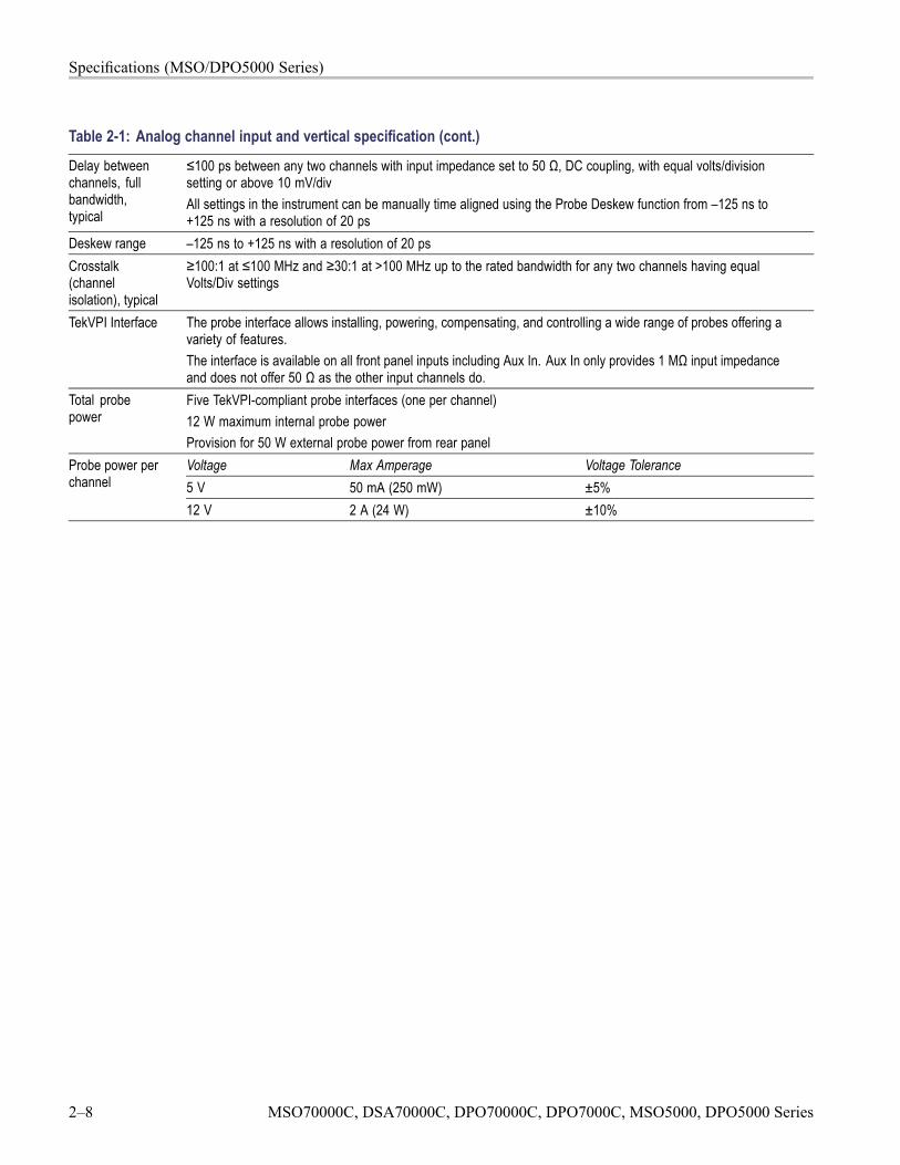
Specifications (MSO/DPO5000 Series)
Table 2-1: Analog channel input and vertical specification (cont.)
Delay betweenchannels, fullbandwidth,typical
≤100 ps between any two channels with input impedance set to 50 Ω, DC coupling, with equal volts/divisionsetting or above 10 mV/divAll settings in the instrument can be manually time aligned using the Probe Deskew function from –125 ns to+125 ns with a resolution of 20 ps
Deskew range –125 ns to +125 ns with a resolution of 20 psCrosstalk(channelisolation), typical
≥100:1 at ≤100 MHz and ≥30:1 at >100 MHz up to the rated bandwidth for any two channels having equalVolts/Div settings
TekVPI Interface The probe interface allows installing, powering, compensating, and controlling a wide range of probes offering avariety of features.The interface is available on all front panel inputs including Aux In. Aux In only provides 1 MΩ input impedanceand does not offer 50 Ω as the other input channels do.
Total probepower
Five TekVPI-compliant probe interfaces (one per channel)12 W maximum internal probe powerProvision for 50 W external probe power from rear panelVoltage Max Amperage Voltage Tolerance5 V 50 mA (250 mW) ±5%
Probe power perchannel
12 V 2 A (24 W) ±10%
2–8 MSO70000C, DSA70000C, DPO70000C, DPO7000C, MSO5000, DPO5000 Series
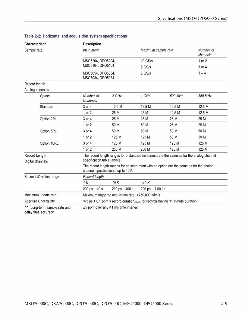
Specifications (MSO/DPO5000 Series)
Table 2-2: Horizontal and acquisition system specificationsCharacteristic Description
Instrument Maximum sample rate Number ofchannels
10 GS/s 1 or 2MSO5204, DPO5204,MSO5104, DPO5104 5 GS/s 3 or 4
Sample rate
MSO5054, DPO5054,MSO5034, DPO5034
5 GS/s 1 – 4
Record lengthAnalog channels
Option Number ofChannels
2 GHz 1 GHz 500 MHz 350 MHz
3 or 4 12.5 M 12.5 M 12.5 M 12.5 MStandard1 or 2 25 M 25 M 12.5 M 12.5 M3 or 4 25 M 25 M 25 M 25 MOption 2RL1 or 2 50 M 50 M 25 M 25 M3 or 4 50 M 50 M 50 M 50 MOption 5RL1 or 2 125 M 125 M 50 M 50 M3 or 4 125 M 125 M 125 M 125 MOption 10RL1 or 2 250 M 250 M 125 M 125 M
Record LengthDigital channels
The record length ranges for a standard instrument are the same as for the analog channelspecification table (above).The record length ranges for an instrument with an option are the same as for the analogchannel specifications, up to 40M.Record length1 K 10 K >10 K
Seconds/Division range
200 ps – 40 s 200 ps – 400 s 200 ps – 1.00 ksMaximum update rate Maximum triggered acquisition rate: >250,000 wfm/sAperture Uncertainty ≤(3 ps + 0.1 ppm × record duration)RMS, for records having ≤1 minute duration
Long-term sample rate anddelay time accuracy
±5 ppm over any ≥1 ms time interval
MSO70000C, DSA70000C, DPO70000C, DPO7000C, MSO5000, DPO5000 Series 2–9
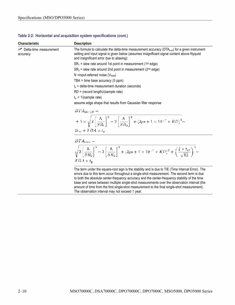
Specifications (MSO/DPO5000 Series)
Table 2-2: Horizontal and acquisition system specifications (cont.)
Characteristic DescriptionThe formula to calculate the delta-time measurement accuracy (DTAmax) for a given instrumentsetting and input signal is given below (assumes insignificant signal content above Nyquistand insignificant error due to aliasing):SR1 = slew rate around 1st point in measurement (1st edge)SR2 = slew rate around 2nd point in measurement (2nd edge)N =input-referred noise (VRMS)TBA = time base accuracy (5 ppm)tp = delta-time measurement duration (seconds)RD = (record length)/(sample rate)tsr = 1/(sample rate)assume edge shape that results from Gaussian filter response
Delta-time measurementaccuracy
The term under the square-root sign is the stability and is due to TIE (Time Interval Error). Theerrors due to this term occur throughout a single-shot measurement. The second term is dueto both the absolute center-frequency accuracy and the center-frequency stability of the timebase and varies between multiple single-shot measurements over the observation interval (theamount of time from the first single-shot measurement to the final single-shot measurement).The observation interval may not exceed 1 year.
2–10 MSO70000C, DSA70000C, DPO70000C, DPO7000C, MSO5000, DPO5000 Series
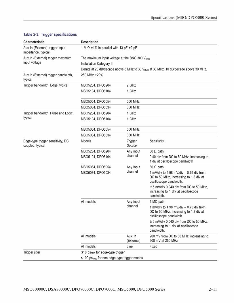
Specifications (MSO/DPO5000 Series)
Table 2-3: Trigger specificationsCharacteristic DescriptionAux In (External) trigger inputimpedance, typical
1 M Ω ±1% in parallel with 13 pF ±2 pF
Aux In (External) trigger maximuminput voltage
The maximum input voltage at the BNC 300 VRMS
Installation Category IIDerate at 20 dB/decade above 3 MHz to 30 VRMS at 30 MHz, 10 dB/decade above 30 MHz.
Aux In (External) trigger bandwidth,typical
250 MHz ±20%
MSO5204, DPO5204 2 GHzMSO5104, DPO5104 1 GHz
MSO5054, DPO5054 500 MHz
Trigger bandwidth, Edge, typical
MSO5034, DPO5034 350 MHzMSO5204, DPO5204 1 GHzMSO5104, DPO5104 1 GHz
MSO5054, DPO5054 500 MHz
Trigger bandwidth, Pulse and Logic,typical
MSO5034, DPO5034 350 MHzModels Trigger
SourceSensitivity
MSO5204, DPO5204MSO5104, DPO5104
Any inputchannel
50 Ω path:0.40 div from DC to 50 MHz, increasing to1 div at oscilloscope bandwidth
MSO5054, DPO5054MSO5034, DPO5034
Any inputchannel
50 Ω path:1 mV/div to 4.98 mV/div – 0.75 div fromDC to 50 MHz, increasing to 1.3 div atoscilloscope bandwidth.≥ 5 mV/div 0.040 div from DC to 50 MHz,increasing to 1 div at oscilloscopebandwidth.
All models Any inputchannel
1 MΩ path:1 mV/div to 4.98 mV/div – 0.75 div fromDC to 50 MHz, increasing to 1.3 div atoscilloscope bandwidth.≥ 5 mV/div 0.040 div from DC to 50 MHz,increasing to 1 div at oscilloscopebandwidth.
All models Aux in(External)
200 mV from DC to 50 MHz, increasing to500 mV at 250 MHz
Edge-type trigger sensitivity, DCcoupled, typical
All models Line FixedTrigger jitter ≤10 psRMS for edge-type trigger
≤100 psRMS for non edge-type trigger modes
MSO70000C, DSA70000C, DPO70000C, DPO7000C, MSO5000, DPO5000 Series 2–11
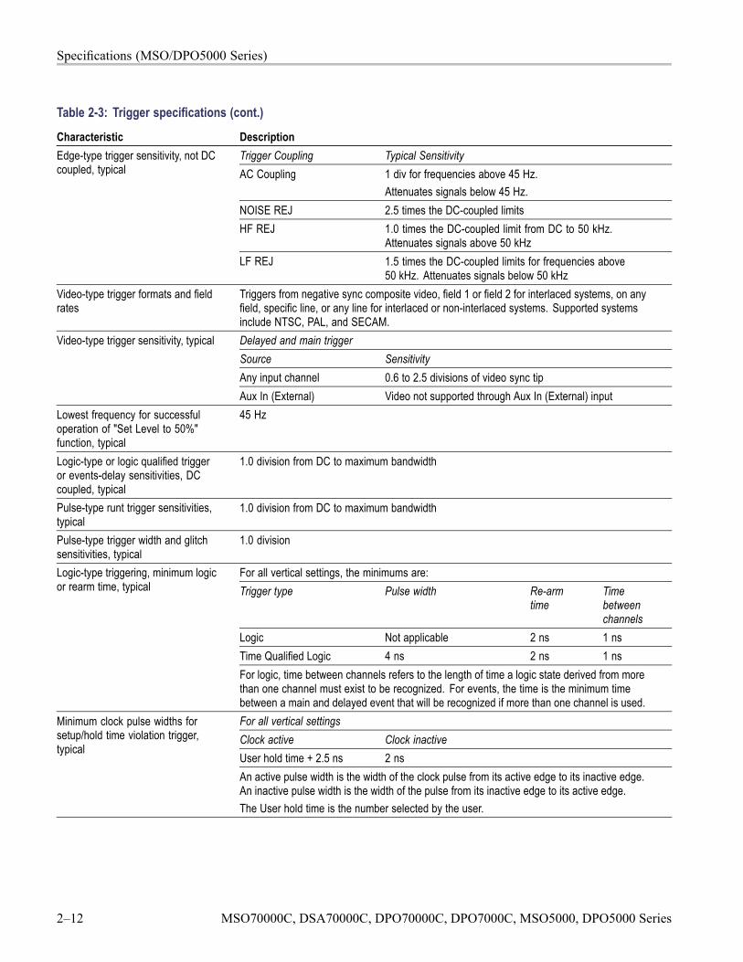
Specifications (MSO/DPO5000 Series)
Table 2-3: Trigger specifications (cont.)
Characteristic DescriptionTrigger Coupling Typical SensitivityAC Coupling 1 div for frequencies above 45 Hz.
Attenuates signals below 45 Hz.NOISE REJ 2.5 times the DC-coupled limitsHF REJ 1.0 times the DC-coupled limit from DC to 50 kHz.
Attenuates signals above 50 kHz
Edge-type trigger sensitivity, not DCcoupled, typical
LF REJ 1.5 times the DC-coupled limits for frequencies above50 kHz. Attenuates signals below 50 kHz
Video-type trigger formats and fieldrates
Triggers from negative sync composite video, field 1 or field 2 for interlaced systems, on anyfield, specific line, or any line for interlaced or non-interlaced systems. Supported systemsinclude NTSC, PAL, and SECAM.Delayed and main triggerSource SensitivityAny input channel 0.6 to 2.5 divisions of video sync tip
Video-type trigger sensitivity, typical
Aux In (External) Video not supported through Aux In (External) inputLowest frequency for successfuloperation of "Set Level to 50%"function, typical
45 Hz
Logic-type or logic qualified triggeror events-delay sensitivities, DCcoupled, typical
1.0 division from DC to maximum bandwidth
Pulse-type runt trigger sensitivities,typical
1.0 division from DC to maximum bandwidth
Pulse-type trigger width and glitchsensitivities, typical
1.0 division
For all vertical settings, the minimums are:Trigger type Pulse width Re-arm
timeTimebetweenchannels
Logic Not applicable 2 ns 1 nsTime Qualified Logic 4 ns 2 ns 1 ns
Logic-type triggering, minimum logicor rearm time, typical
For logic, time between channels refers to the length of time a logic state derived from morethan one channel must exist to be recognized. For events, the time is the minimum timebetween a main and delayed event that will be recognized if more than one channel is used.For all vertical settingsClock active Clock inactiveUser hold time + 2.5 ns 2 ns
Minimum clock pulse widths forsetup/hold time violation trigger,typical
An active pulse width is the width of the clock pulse from its active edge to its inactive edge.An inactive pulse width is the width of the pulse from its inactive edge to its active edge.The User hold time is the number selected by the user.
2–12 MSO70000C, DSA70000C, DPO70000C, DPO7000C, MSO5000, DPO5000 Series
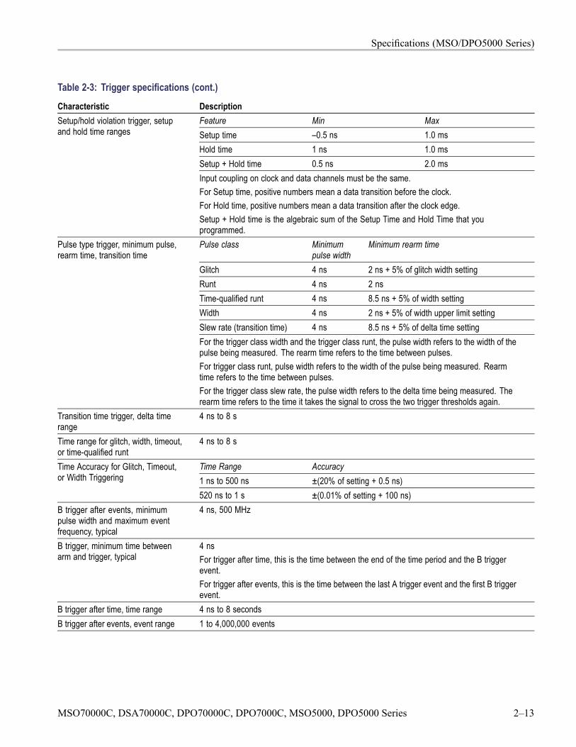
Specifications (MSO/DPO5000 Series)
Table 2-3: Trigger specifications (cont.)
Characteristic DescriptionFeature Min MaxSetup time –0.5 ns 1.0 msHold time 1 ns 1.0 msSetup + Hold time 0.5 ns 2.0 ms
Setup/hold violation trigger, setupand hold time ranges
Input coupling on clock and data channels must be the same.For Setup time, positive numbers mean a data transition before the clock.For Hold time, positive numbers mean a data transition after the clock edge.Setup + Hold time is the algebraic sum of the Setup Time and Hold Time that youprogrammed.Pulse class Minimum
pulse widthMinimum rearm time
Glitch 4 ns 2 ns + 5% of glitch width settingRunt 4 ns 2 nsTime-qualified runt 4 ns 8.5 ns + 5% of width settingWidth 4 ns 2 ns + 5% of width upper limit settingSlew rate (transition time) 4 ns 8.5 ns + 5% of delta time setting
Pulse type trigger, minimum pulse,rearm time, transition time
For the trigger class width and the trigger class runt, the pulse width refers to the width of thepulse being measured. The rearm time refers to the time between pulses.For trigger class runt, pulse width refers to the width of the pulse being measured. Rearmtime refers to the time between pulses.For the trigger class slew rate, the pulse width refers to the delta time being measured. Therearm time refers to the time it takes the signal to cross the two trigger thresholds again.
Transition time trigger, delta timerange
4 ns to 8 s
Time range for glitch, width, timeout,or time-qualified runt
4 ns to 8 s
Time Range Accuracy1 ns to 500 ns ±(20% of setting + 0.5 ns)
Time Accuracy for Glitch, Timeout,or Width Triggering
520 ns to 1 s ±(0.01% of setting + 100 ns)B trigger after events, minimumpulse width and maximum eventfrequency, typical
4 ns, 500 MHz
B trigger, minimum time betweenarm and trigger, typical
4 nsFor trigger after time, this is the time between the end of the time period and the B triggerevent.For trigger after events, this is the time between the last A trigger event and the first B triggerevent.
B trigger after time, time range 4 ns to 8 secondsB trigger after events, event range 1 to 4,000,000 events
MSO70000C, DSA70000C, DPO70000C, DPO7000C, MSO5000, DPO5000 Series 2–13
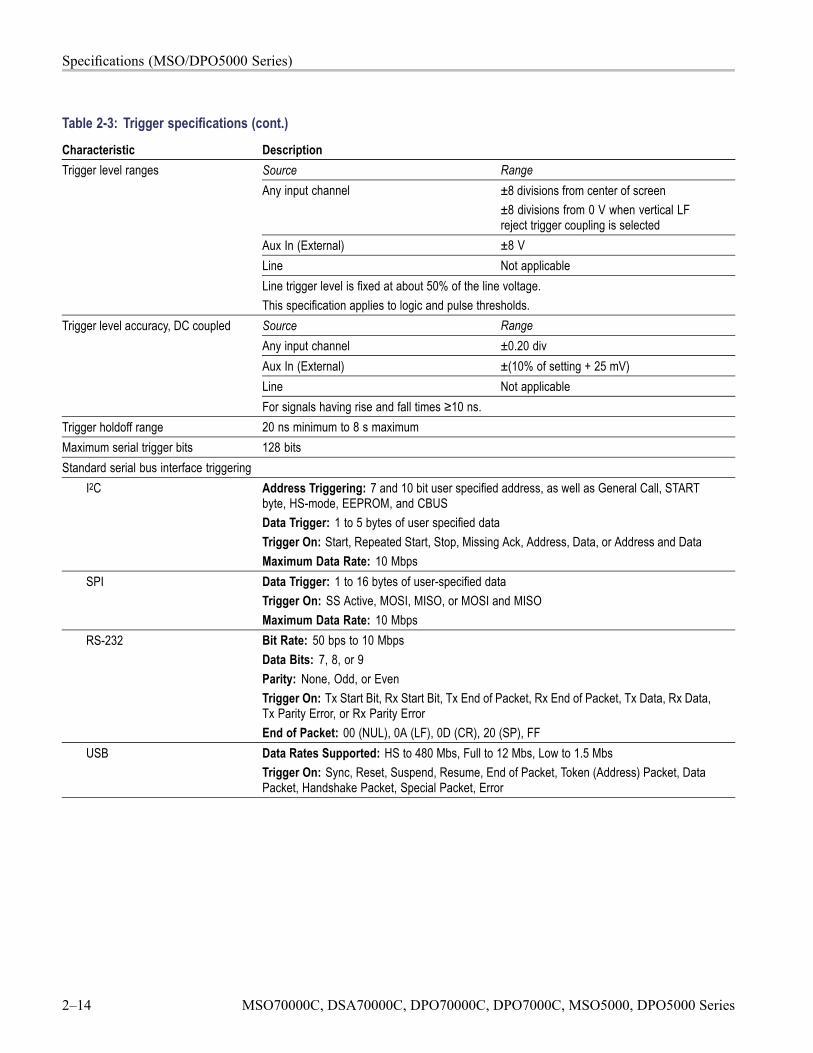
Specifications (MSO/DPO5000 Series)
Table 2-3: Trigger specifications (cont.)
Characteristic DescriptionSource RangeAny input channel ±8 divisions from center of screen
±8 divisions from 0 V when vertical LFreject trigger coupling is selected
Aux In (External) ±8 VLine Not applicable
Trigger level ranges
Line trigger level is fixed at about 50% of the line voltage.This specification applies to logic and pulse thresholds.Source RangeAny input channel ±0.20 divAux In (External) ±(10% of setting + 25 mV)Line Not applicable
Trigger level accuracy, DC coupled
For signals having rise and fall times ≥10 ns.Trigger holdoff range 20 ns minimum to 8 s maximumMaximum serial trigger bits 128 bitsStandard serial bus interface triggering
I2C Address Triggering: 7 and 10 bit user specified address, as well as General Call, STARTbyte, HS-mode, EEPROM, and CBUSData Trigger: 1 to 5 bytes of user specified dataTrigger On: Start, Repeated Start, Stop, Missing Ack, Address, Data, or Address and DataMaximum Data Rate: 10 Mbps
SPI Data Trigger: 1 to 16 bytes of user-specified dataTrigger On: SS Active, MOSI, MISO, or MOSI and MISOMaximum Data Rate: 10 Mbps
RS-232 Bit Rate: 50 bps to 10 MbpsData Bits: 7, 8, or 9Parity: None, Odd, or EvenTrigger On: Tx Start Bit, Rx Start Bit, Tx End of Packet, Rx End of Packet, Tx Data, Rx Data,Tx Parity Error, or Rx Parity ErrorEnd of Packet: 00 (NUL), 0A (LF), 0D (CR), 20 (SP), FF
USB Data Rates Supported: HS to 480 Mbs, Full to 12 Mbs, Low to 1.5 MbsTrigger On: Sync, Reset, Suspend, Resume, End of Packet, Token (Address) Packet, DataPacket, Handshake Packet, Special Packet, Error
2–14 MSO70000C, DSA70000C, DPO70000C, DPO7000C, MSO5000, DPO5000 Series

Specifications (MSO/DPO5000 Series)
Table 2-4: Digital acquisition specifications, MSO5000 SeriesCharacteristic DescriptionThreshold voltage range -40 V to +40 VDigital channel timing resolution 2 ns main memory, 60.6 ps for MagniVu memory
Logic threshold accuracy ±(100 mV + 3% of threshold setting after calibration)Requires valid SPC. (See page 4-26, Self Test.)
Minimum detectable pulse width 1 nsUsing MagniVu memory. Requires the use of 342-1140-00 ground clip per channel.
Table 2-5: P6616 Digital Probe specificationsCharacteristic DescriptionNumber of channels 16 digital inputsInput resistance, Typical 100 kΩ to groundInput capacitance, Typical 3.0 pF
Measured at the podlet input. Requires the use of 342-1140-00 ground clip per channelMinimum input signal swing 400 mVp-p
Requires the use of 342-1140-00 ground clip per channelMaximum input signal swing 30 Vp-p for fin ≤ 200 MHz (centered around the DC threshold voltage) at the P6616
probe tip.10 Vp-p for fin >200 MHz (centered around the DC threshold voltage) at the P6616probe tip.Failure to meet this input signal requirement will compromise the AC performance of thedigital channel. It might also damage the input circuitry. See the Absolute maximuminput voltage specification.
Maximum Input Toggle Rate 500 MHzMaximum frequency sine wave input that can accurately be reproduced as a logicsquare wave.Requires the use of a 342-1140-00 ground clip on each channel.This is the maximum frequency at the minimum swing amplitude. Higher toggle ratescan be achieved with higher amplitudes.
Absolute maximum input voltage ±42 V peak at the P6616 input (not at the instrument input)Probe input voltages beyond this limit could permanently damage the instrument andthe P6616 probe.
Channel-to-channel skew 200 psDigital channel to digital channel only.This is the propagation path skew and ignores skew contributions due to thresholdinaccuracies (see Threshold accuracy) and sample binning (see Digital channel timingresolution). Factory calibration/deskew is required to achieve this number.
MSO70000C, DSA70000C, DPO70000C, DPO7000C, MSO5000, DPO5000 Series 2–15
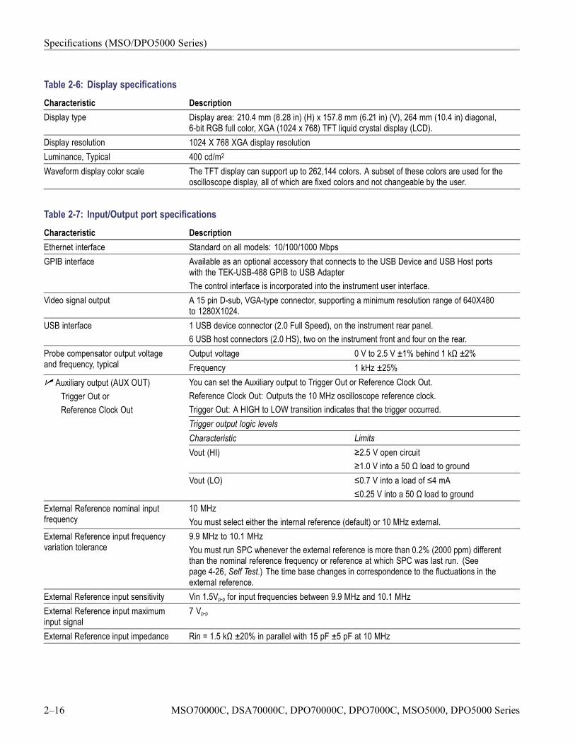
Specifications (MSO/DPO5000 Series)
Table 2-6: Display specificationsCharacteristic DescriptionDisplay type Display area: 210.4 mm (8.28 in) (H) x 157.8 mm (6.21 in) (V), 264 mm (10.4 in) diagonal,
6-bit RGB full color, XGA (1024 x 768) TFT liquid crystal display (LCD).Display resolution 1024 X 768 XGA display resolutionLuminance, Typical 400 cd/m2
Waveform display color scale The TFT display can support up to 262,144 colors. A subset of these colors are used for theoscilloscope display, all of which are fixed colors and not changeable by the user.
Table 2-7: Input/Output port specificationsCharacteristic DescriptionEthernet interface Standard on all models: 10/100/1000 MbpsGPIB interface Available as an optional accessory that connects to the USB Device and USB Host ports
with the TEK-USB-488 GPIB to USB AdapterThe control interface is incorporated into the instrument user interface.
Video signal output A 15 pin D-sub, VGA-type connector, supporting a minimum resolution range of 640X480to 1280X1024.
USB interface 1 USB device connector (2.0 Full Speed), on the instrument rear panel.6 USB host connectors (2.0 HS), two on the instrument front and four on the rear.Output voltage 0 V to 2.5 V ±1% behind 1 kΩ ±2%Probe compensator output voltage
and frequency, typical Frequency 1 kHz ±25%You can set the Auxiliary output to Trigger Out or Reference Clock Out.Reference Clock Out: Outputs the 10 MHz oscilloscope reference clock.Trigger Out: A HIGH to LOW transition indicates that the trigger occurred.Trigger output logic levelsCharacteristic LimitsVout (HI) ≥2.5 V open circuit
≥1.0 V into a 50 Ω load to ground
Auxiliary output (AUX OUT)Trigger Out orReference Clock Out
Vout (LO) ≤0.7 V into a load of ≤4 mA≤0.25 V into a 50 Ω load to ground
External Reference nominal inputfrequency
10 MHzYou must select either the internal reference (default) or 10 MHz external.
External Reference input frequencyvariation tolerance
9.9 MHz to 10.1 MHzYou must run SPC whenever the external reference is more than 0.2% (2000 ppm) differentthan the nominal reference frequency or reference at which SPC was last run. (Seepage 4-26, Self Test.) The time base changes in correspondence to the fluctuations in theexternal reference.
External Reference input sensitivity Vin 1.5Vp-p for input frequencies between 9.9 MHz and 10.1 MHzExternal Reference input maximuminput signal
7 Vp-p
External Reference input impedance Rin = 1.5 kΩ ±20% in parallel with 15 pF ±5 pF at 10 MHz
2–16 MSO70000C, DSA70000C, DPO70000C, DPO7000C, MSO5000, DPO5000 Series
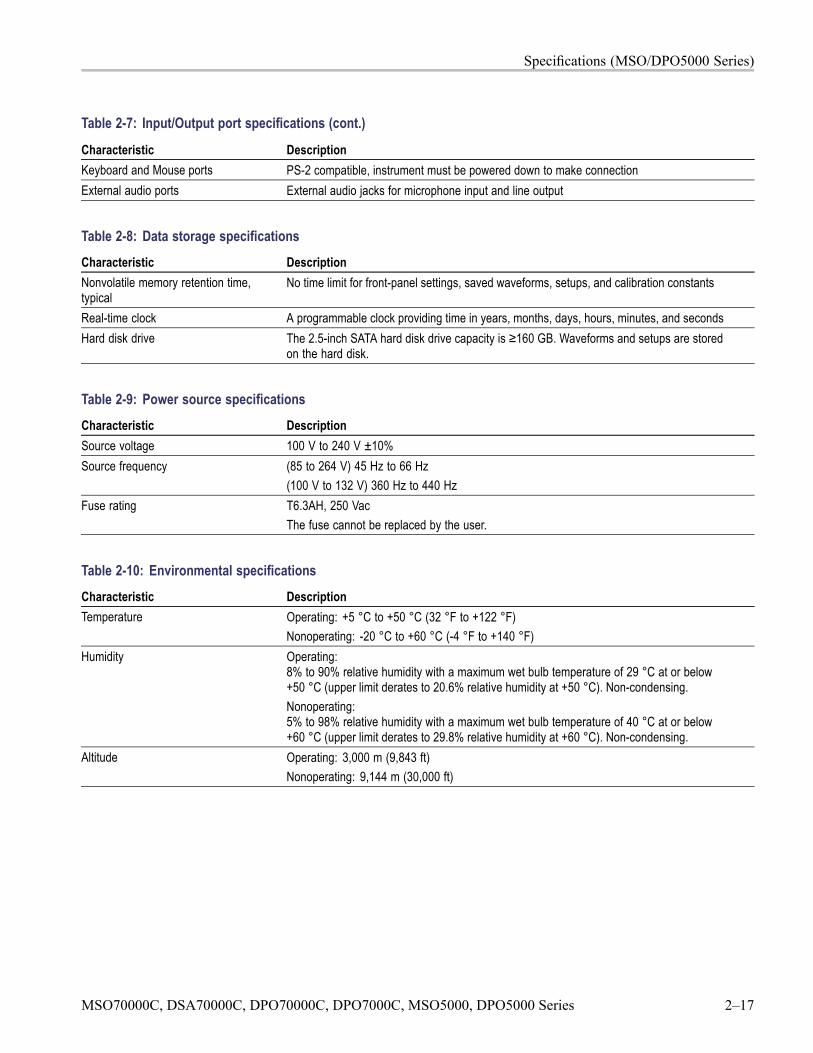
Specifications (MSO/DPO5000 Series)
Table 2-7: Input/Output port specifications (cont.)
Characteristic DescriptionKeyboard and Mouse ports PS-2 compatible, instrument must be powered down to make connectionExternal audio ports External audio jacks for microphone input and line output
Table 2-8: Data storage specificationsCharacteristic DescriptionNonvolatile memory retention time,typical
No time limit for front-panel settings, saved waveforms, setups, and calibration constants
Real-time clock A programmable clock providing time in years, months, days, hours, minutes, and secondsHard disk drive The 2.5-inch SATA hard disk drive capacity is ≥160 GB. Waveforms and setups are stored
on the hard disk.
Table 2-9: Power source specificationsCharacteristic DescriptionSource voltage 100 V to 240 V ±10%Source frequency (85 to 264 V) 45 Hz to 66 Hz
(100 V to 132 V) 360 Hz to 440 HzFuse rating T6.3AH, 250 Vac
The fuse cannot be replaced by the user.
Table 2-10: Environmental specificationsCharacteristic DescriptionTemperature Operating: +5 °C to +50 °C (32 °F to +122 °F)
Nonoperating: -20 °C to +60 °C (-4 °F to +140 °F)Humidity Operating:
8% to 90% relative humidity with a maximum wet bulb temperature of 29 °C at or below+50 °C (upper limit derates to 20.6% relative humidity at +50 °C). Non-condensing.Nonoperating:5% to 98% relative humidity with a maximum wet bulb temperature of 40 °C at or below+60 °C (upper limit derates to 29.8% relative humidity at +60 °C). Non-condensing.
Altitude Operating: 3,000 m (9,843 ft)Nonoperating: 9,144 m (30,000 ft)
MSO70000C, DSA70000C, DPO70000C, DPO7000C, MSO5000, DPO5000 Series 2–17
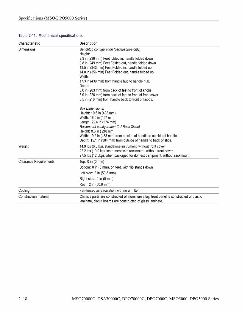
Specifications (MSO/DPO5000 Series)
Table 2-11: Mechanical specificationsCharacteristic DescriptionDimensions Benchtop configuration (oscilloscope only)
Height:9.3 in (236 mm) Feet folded in, handle folded down9.8 in (249 mm) Feet Folded out, handle folded down13.5 in (343 mm) Feet Folded in, handle folded up14.0 in (356 mm) Feet Folded out, handle folded upWidth:17.3 in (439 mm) from handle hub to handle hub.Depth:8.0 in (203 mm) from back of feet to front of knobs.8.9 in (226 mm) from back of feet to front of front cover8.5 in (216 mm) from handle back to front of knobs.
Box Dimensions:Height: 19.6 in (498 mm)Width: 18.0 in (457 mm)Length: 22.6 in (574 mm)Rackmount configuration (5U Rack Sizes)Height: 8.6 in ( 218 mm)Width: 19.2 in (488 mm) from outside of handle to outside of handle.Depth: 15.1 in (384 mm) from outside of handle to back of slide.
Weight 14.9 lbs (6.8 kg), standalone instrument, without front cover22.2 lbs (10.0 kg), instrument with rackmount, without front cover27.5 lbs (12.5kg), when packaged for domestic shipment, without rackmount
Clearance Requirements Top: 0 in (0 mm)Bottom: 0 in (0 mm), on feet, with flip stands downLeft side: 2 in (50.8 mm)Right side: 0 in (0 mm)Rear: 2 in (50.8 mm)
Cooling Fan-forced air circulation with no air filter.Construction material Chassis parts are constructed of aluminum alloy, front panel is constructed of plastic
laminate, circuit boards are constructed of glass laminate.
2–18 MSO70000C, DSA70000C, DPO70000C, DPO7000C, MSO5000, DPO5000 Series

Performance Verification(MSO/DSA/DPO70000C Series and
DPO7000C Series)

Performance Verification (MSO/DSA/DPO70000C Seriesand DPO7000C Series)
Two types of Performance Verification procedures can be performed on theseproducts: Brief Procedures and Performance Tests. You may not need to performall of these procedures, depending on what you want to accomplish.
If you are not familiar with operating this instrument, read the instrument usermanual or explore the online help.
To rapidly confirm that the instrument functions and was adjusted properly,perform only the brief procedures under Self Tests.
Advantages. These procedures are quick to do, require no external equipmentor signal sources, and perform extensive functional and accuracy testing toprovide high confidence that the instrument will perform properly. They canbe used as a quick check before making a series of important measurements.
To further check functionality, first do the Self Tests just mentioned; then dothe brief procedures under Functional Tests.
Advantages. These procedures require minimal additional time to perform,require no additional equipment other than cables and adapters, and theseprocedures more completely test the internal hardware of the instrument.They can be used to quickly determine if the instrument is suitable for puttinginto service, such as when it is first received.
If more extensive confirmation of performance is desired, perform thePerformance Tests after performing the Functional and Self Tests mentionedabove. (See page 3-18, Performance Tests (MSO/DSA/DPO70000C Seriesand DPO7000C Series).)
Advantages. These procedures add direct checking of the warrantedspecifications that are marked with the symbol. These procedures requirespecific test equipment. (See Table 3-2.)
MSO70000C, DSA70000C, DPO70000C, DPO7000C, MSO5000, DPO5000 Series 3–1
Performance Verification (MSO/DSA/DPO70000C Series and DPO7000C Series)
ConventionsThroughout these procedures the following conventions apply:
Each test procedure uses the following general format:
Title of Test
Equipment Required
Prerequisites
Procedure
Each procedure consists of as many steps, substeps, and subparts as requiredto do the test. Steps, substeps, and subparts are sequenced as follows:
1. First Step
a. First Substep
First Subpart
Second Subpart
b. Second Substep
2. Second Step
In steps and substeps, the lead-in statement in italics instructs you what to do,while the instructions that follow tell you how to do it, as in the examplestep below:
Initialize the instrument: Push the front-panel Default Setup button.
STOP. The STOP notation at the left is accompanied by information you mustread to do the procedure properly.
The term "toolbar" refers to a row of buttons at the top of the display. Theterm "menu bar" refers to a row of menus at the top of the display. You canswitch between toolbar and menu bar operating modes by using the menu atthe top right of the toolbar or menu bar. (See Figure 3-1.)
Item numbers in the equipment required lists refer to the equipment. (SeeTable 3-2 on page 3-19.)
3–2 MSO70000C, DSA70000C, DPO70000C, DPO7000C, MSO5000, DPO5000 Series
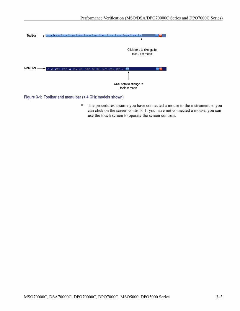
Performance Verification (MSO/DSA/DPO70000C Series and DPO7000C Series)
Figure 3-1: Toolbar and menu bar (< 4 GHz models shown)
The procedures assume you have connected a mouse to the instrument so youcan click on the screen controls. If you have not connected a mouse, you canuse the touch screen to operate the screen controls.
MSO70000C, DSA70000C, DPO70000C, DPO7000C, MSO5000, DPO5000 Series 3–3
Brief Procedures (MSO/DSA/DPO70000C Series and DPO7000C Series)
Brief Procedures (MSO/DSA/DPO70000C Series andDPO7000C Series)
The Self Tests use internal routines to confirm basic functionality and properadjustment. No test equipment is required to do these test procedures.
The Functional Tests utilize the probe-compensation output at the front panel as atest-signal source for further verifying that the instrument functions properly. ABNC cable and an adaptor or a probe, depending on your instrument model arerequired to do these test procedures.
Self TestsThis procedure uses internal routines to verify that the instrument functions andwas adjusted properly. No test equipment or hookups are required.
Equipment required PrerequisitesNone Power on the instrument and allow a
20 minute warm-up before doing thisprocedure.
1. Verify that internal diagnostics pass: Do the following substeps to verifypassing of internal diagnostics.
a. Display the System diagnostics menu:
If the instrument is in toolbar mode, put the instrument into menu barmode.
Pull down the Utilities menu and select Instrument Diagnostics. . . .This displays the diagnostics control window.
b. Run the System Diagnostics:
First disconnect any input signals from all four channels.
Click the Run button in the diagnostics control window.
c. Wait: The internal diagnostics do an exhaustive verification of properinstrument function. This verification may take several minutes. When theverification is finished, the resulting status will appear in the diagnosticscontrol window.
d. Verify that no failures are found and reported on-screen. All tests shouldpass.
3–4 MSO70000C, DSA70000C, DPO70000C, DPO7000C, MSO5000, DPO5000 Series
Brief Procedures (MSO/DSA/DPO70000C Series and DPO7000C Series)
e. Run the signal-path compensation routine:
Pull down the Utilities menu and select Instrument Calibration. . . .This displays the instrument calibration control window.
If required because the instrument is in service mode, select the SignalPath button under Calibration Area.
Click the Run SPC (Calibrate on some instruments) button to start theroutine.
f. Wait: Signal-path compensation may take five to fifteen minutes to run.
g. Confirm signal-path compensation returns passed status: Verify that theword Pass appears in the instrument calibration control window.
2. Return to regular service: Click the X (close) button to exit the instrumentcalibration control window.
Functional TestsThe purpose of these procedures is to confirm that the instrument functionsproperly. The only equipment required is a BNC or SMA cable and an adapter orthe instrument probe. If you need to store settings during these procedures, accessthe local C: drive and store them in the TekScope > Setups directory.
STOP. These procedures verify functions; that is, they verify that the instrumentfeatures operate. They do not verify that they operate within limits.
Therefore, when the instructions in the functional tests that follow call for you toverify that a signal appears on-screen "that is about five divisions in amplitude"or "has a period of about six horizontal divisions," etc., do NOT interpret thequantities given as limits. Operation within limits is checked in PerformanceTests. (See page 3-18, Performance Tests (MSO/DSA/DPO70000C Series andDPO7000C Series).)
STOP. DO NOT make changes to the front-panel settings that are not calledout in the procedures. Each verification procedure will require you to set theinstrument to certain default settings before verifying functions. If you makechanges to these settings, other than those called out in the procedure, you mayobtain invalid results. In this case, just redo the procedure from step 1.
When you are instructed to press a front-panel or screen button, the button mayalready be selected (its label will be highlighted). If this is the case, it is notnecessary to press the button.
MSO70000C, DSA70000C, DPO70000C, DPO7000C, MSO5000, DPO5000 Series 3–5
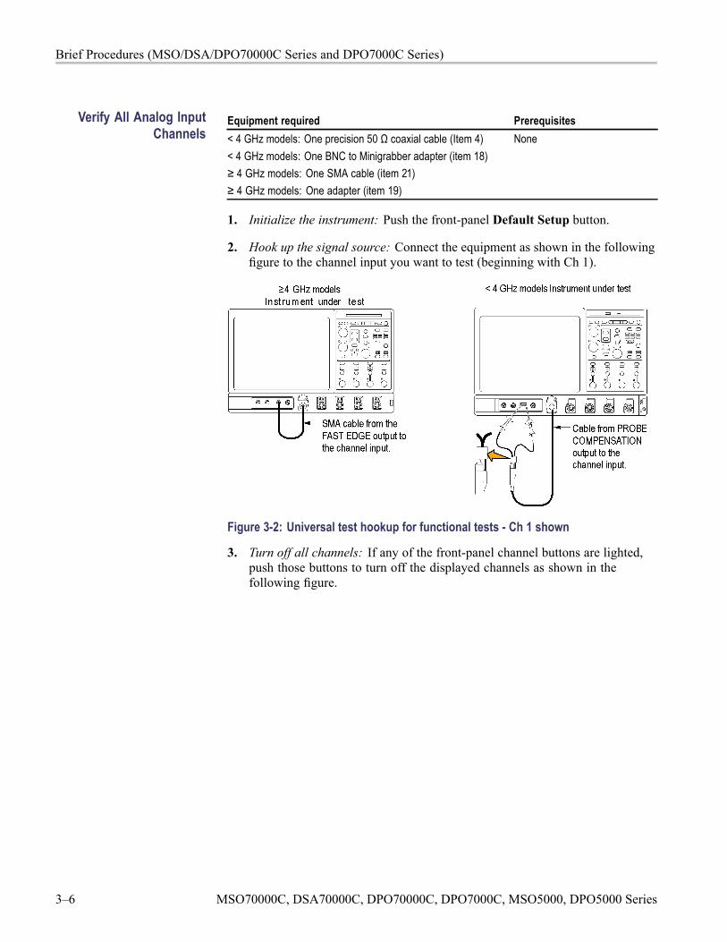
Brief Procedures (MSO/DSA/DPO70000C Series and DPO7000C Series)
Verify All Analog InputChannels
Equipment required Prerequisites< 4 GHz models: One precision 50 Ω coaxial cable (Item 4)< 4 GHz models: One BNC to Minigrabber adapter (item 18)≥ 4 GHz models: One SMA cable (item 21)≥ 4 GHz models: One adapter (item 19)
None
1. Initialize the instrument: Push the front-panel Default Setup button.
2. Hook up the signal source: Connect the equipment as shown in the followingfigure to the channel input you want to test (beginning with Ch 1).
Figure 3-2: Universal test hookup for functional tests - Ch 1 shown
3. Turn off all channels: If any of the front-panel channel buttons are lighted,push those buttons to turn off the displayed channels as shown in thefollowing figure.
3–6 MSO70000C, DSA70000C, DPO70000C, DPO7000C, MSO5000, DPO5000 Series
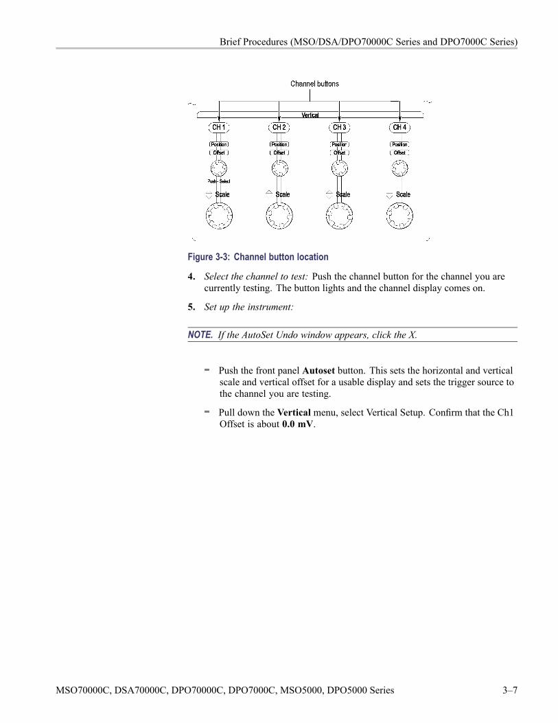
Brief Procedures (MSO/DSA/DPO70000C Series and DPO7000C Series)
Figure 3-3: Channel button location
4. Select the channel to test: Push the channel button for the channel you arecurrently testing. The button lights and the channel display comes on.
5. Set up the instrument:
NOTE. If the AutoSet Undo window appears, click the X.
Push the front panel Autoset button. This sets the horizontal and verticalscale and vertical offset for a usable display and sets the trigger source tothe channel you are testing.
Pull down the Vertical menu, select Vertical Setup. Confirm that the Ch1Offset is about 0.0 mV.
MSO70000C, DSA70000C, DPO70000C, DPO7000C, MSO5000, DPO5000 Series 3–7
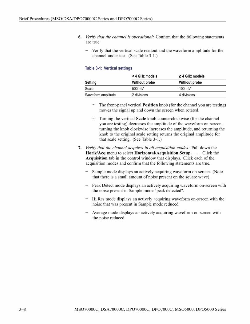
Brief Procedures (MSO/DSA/DPO70000C Series and DPO7000C Series)
6. Verify that the channel is operational: Confirm that the following statementsare true.
Verify that the vertical scale readout and the waveform amplitude for thechannel under test. (See Table 3-1.)
Table 3-1: Vertical settings< 4 GHz models ≥ 4 GHz models
Setting Without probe Without probeScale 500 mV 100 mVWaveform amplitude 2 divisions 4 divisions
The front-panel vertical Position knob (for the channel you are testing)moves the signal up and down the screen when rotated.
Turning the vertical Scale knob counterclockwise (for the channelyou are testing) decreases the amplitude of the waveform on-screen,turning the knob clockwise increases the amplitude, and returning theknob to the original scale setting returns the original amplitude forthat scale setting. (See Table 3-1.)
7. Verify that the channel acquires in all acquisition modes: Pull down theHoriz/Acq menu to select Horizontal/Acquisition Setup. . . . Click theAcquisition tab in the control window that displays. Click each of theacquisition modes and confirm that the following statements are true.
Sample mode displays an actively acquiring waveform on-screen. (Notethat there is a small amount of noise present on the square wave).
Peak Detect mode displays an actively acquiring waveform on-screen withthe noise present in Sample mode "peak detected".
Hi Res mode displays an actively acquiring waveform on-screen with thenoise that was present in Sample mode reduced.
Average mode displays an actively acquiring waveform on-screen withthe noise reduced.
3–8 MSO70000C, DSA70000C, DPO70000C, DPO7000C, MSO5000, DPO5000 Series
Brief Procedures (MSO/DSA/DPO70000C Series and DPO7000C Series)
Envelope mode displays an actively acquiring waveform on-screen withthe noise displayed.
NOTE. Default setup enables enhanced triggering. Enhanced triggering cancause a slower acquisition rate that can be noticed in waveform database mode.As waveform database mode acquires 100,000 samples, the display intensitywill increase, be cleared, and then the process will start over. When enhancedtriggering is turned off, and with the specified settings and input signal, thedisplay reaches full intensity right away.
Waveform Database mode displays an actively acquiring waveformon-screen with the noise displayed.
8. Test all channels: Repeat steps 2 through 7 until all four input channels areverified.
9. Remove the test hookup: Disconnect the equipment from the instrument.
Verify the Time Base Equipment required Prerequisites< 4 GHz models: One precision 50 Ω coaxialcable (Item 4)< 4 GHz models: One BNC to Minigrabberadapter (item 18)≥ 4 GHz models: One SMA cable (item 21)≥ 4 GHz models: One adapter (item 19)
None
1. Initialize the instrument: Push the front-panel Default Setup button.
2. Hook up the signal source: Connect the probe compensation or fast edgeoutput to the Ch 1 input as shown in the following figure.
MSO70000C, DSA70000C, DPO70000C, DPO7000C, MSO5000, DPO5000 Series 3–9
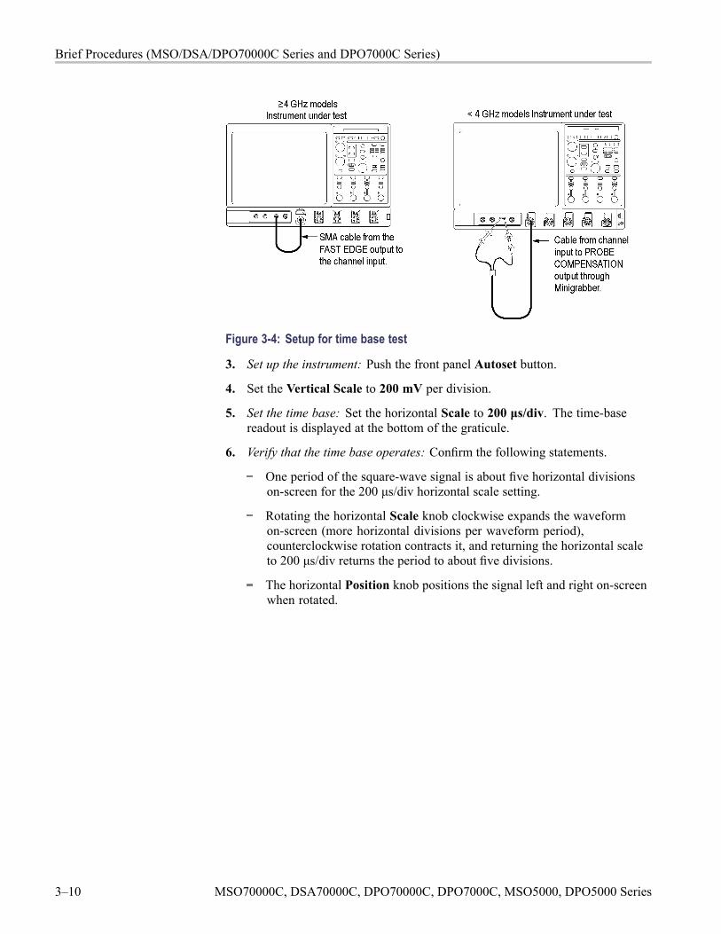
Brief Procedures (MSO/DSA/DPO70000C Series and DPO7000C Series)
Figure 3-4: Setup for time base test
3. Set up the instrument: Push the front panel Autoset button.
4. Set the Vertical Scale to 200 mV per division.
5. Set the time base: Set the horizontal Scale to 200 μs/div. The time-basereadout is displayed at the bottom of the graticule.
6. Verify that the time base operates: Confirm the following statements.
One period of the square-wave signal is about five horizontal divisionson-screen for the 200 μs/div horizontal scale setting.
Rotating the horizontal Scale knob clockwise expands the waveformon-screen (more horizontal divisions per waveform period),counterclockwise rotation contracts it, and returning the horizontal scaleto 200 μs/div returns the period to about five divisions.
The horizontal Position knob positions the signal left and right on-screenwhen rotated.
3–10 MSO70000C, DSA70000C, DPO70000C, DPO7000C, MSO5000, DPO5000 Series
Brief Procedures (MSO/DSA/DPO70000C Series and DPO7000C Series)
7. Verify horizontal delay:
a. Center a rising edge on screen:
Set the horizontal Position knob so that the rising edge where thewaveform is triggered is lined up with the center horizontal graticule.
Change the horizontal Scale to 20 μs/div. The rising edge of thewaveform should remain near the center graticule and the falling edgeshould be off screen.
b. Turn on and set horizontal delay:
Pull down the Horiz/Acq menu to select Horizontal/AcquisitionSetup. . . .
Click the Horizontal tab in the control window that displays.
Click the Delay Mode button to turn delay on.
Double click the Horiz Delay control in the control window to displaythe pop-up keypad. Click the keypad buttons to set the horizontaldelay to 1 ms and then click the ENTER key.
c. Verify the waveform: Verify that a rising edge of the waveform is within afew divisions of center screen.
d. Adjust the horizontal delay: Rotate the upper multipurpose knob to changethe horizontal delay setting. Verify that the rising edge shifts horizontally.Rotate the front-panel horizontal Position knob. Verify that this knob hasthe same effect (it also adjusts delay, but only when delay mode is on).
e. Verify the delay toggle function:
Rotate the front-panel horizontal Position knob to center the risingedge horizontally on the screen.
Change the horizontal Scale to 50 ns/div (< 4 GHz models) or40 ns/div (≥ 4 GHz models). The rising edge of the waveform shouldremain near the center graticule.
Readjust the delay setting to position the rising edge 2 divisions to theright of the center graticule line.
Push the front-panel Delay button several times to toggle delay offand on and back off again. Verify that the display switches quicklybetween two different points in time (the rising edge shifts horizontallyon the display).
8. Remove the test hookup: Disconnect the test hookup from the instrument.
MSO70000C, DSA70000C, DPO70000C, DPO7000C, MSO5000, DPO5000 Series 3–11
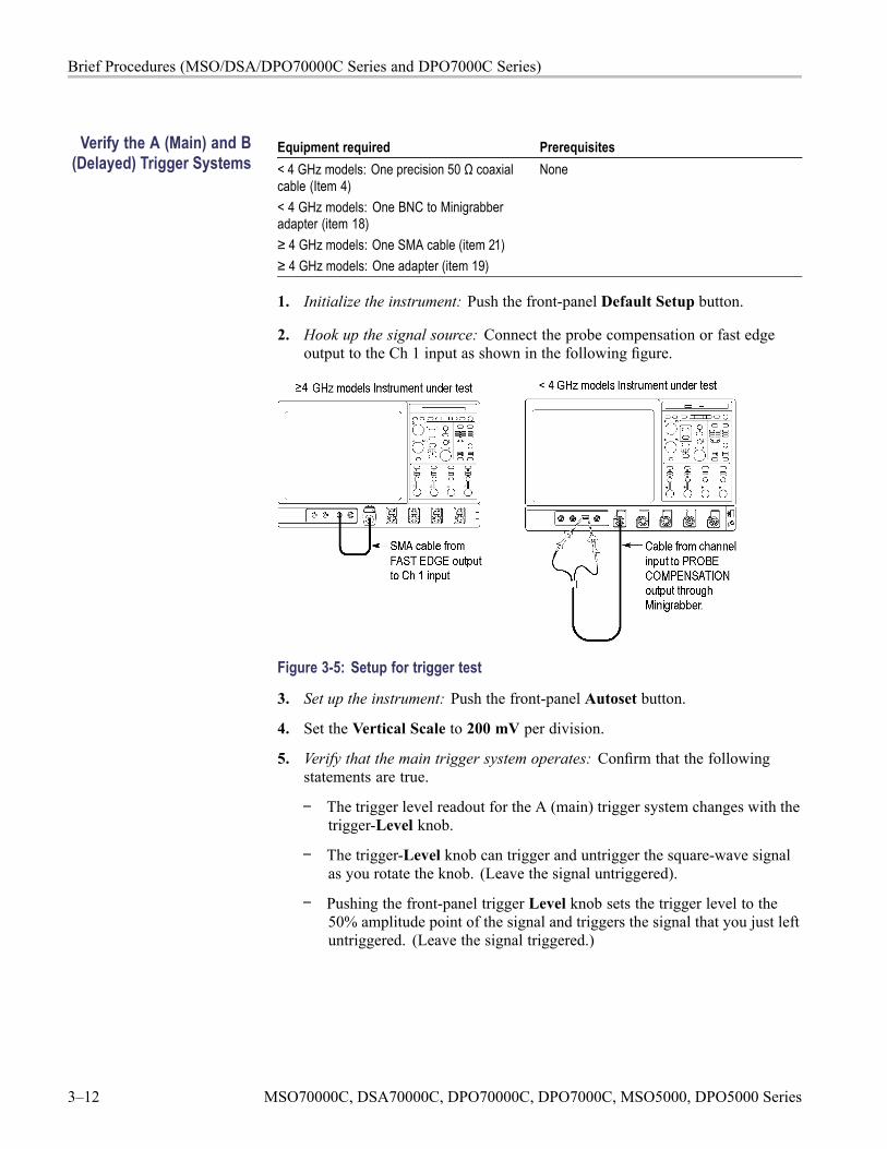
Brief Procedures (MSO/DSA/DPO70000C Series and DPO7000C Series)
Verify the A (Main) and B(Delayed) Trigger Systems
Equipment required Prerequisites< 4 GHz models: One precision 50 Ω coaxialcable (Item 4)< 4 GHz models: One BNC to Minigrabberadapter (item 18)≥ 4 GHz models: One SMA cable (item 21)≥ 4 GHz models: One adapter (item 19)
None
1. Initialize the instrument: Push the front-panel Default Setup button.
2. Hook up the signal source: Connect the probe compensation or fast edgeoutput to the Ch 1 input as shown in the following figure.
Figure 3-5: Setup for trigger test
3. Set up the instrument: Push the front-panel Autoset button.
4. Set the Vertical Scale to 200 mV per division.
5. Verify that the main trigger system operates: Confirm that the followingstatements are true.
The trigger level readout for the A (main) trigger system changes with thetrigger-Level knob.
The trigger-Level knob can trigger and untrigger the square-wave signalas you rotate the knob. (Leave the signal untriggered).
Pushing the front-panel trigger Level knob sets the trigger level to the50% amplitude point of the signal and triggers the signal that you just leftuntriggered. (Leave the signal triggered.)
3–12 MSO70000C, DSA70000C, DPO70000C, DPO7000C, MSO5000, DPO5000 Series
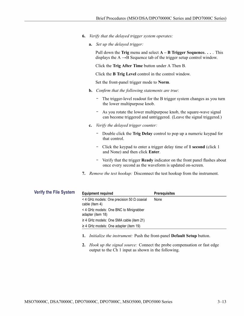
Brief Procedures (MSO/DSA/DPO70000C Series and DPO7000C Series)
6. Verify that the delayed trigger system operates:
a. Set up the delayed trigger:
Pull down the Trig menu and select A – B Trigger Sequence. . . . Thisdisplays the A→B Sequence tab of the trigger setup control window.
Click the Trig After Time button under A Then B.
Click the B Trig Level control in the control window.
Set the front-panel trigger mode to Norm.
b. Confirm that the following statements are true:
The trigger-level readout for the B trigger system changes as you turnthe lower multipurpose knob.
As you rotate the lower multipurpose knob, the square-wave signalcan become triggered and untriggered. (Leave the signal triggered.)
c. Verify the delayed trigger counter:
Double click the Trig Delay control to pop up a numeric keypad forthat control.
Click the keypad to enter a trigger delay time of 1 second (click 1and None) and then click Enter.
Verify that the trigger Ready indicator on the front panel flashes aboutonce every second as the waveform is updated on-screen.
7. Remove the test hookup: Disconnect the test hookup from the instrument.
Verify the File System Equipment required Prerequisites< 4 GHz models: One precision 50 Ω coaxialcable (Item 4)< 4 GHz models: One BNC to Minigrabberadapter (item 18)≥ 4 GHz models: One SMA cable (item 21)≥ 4 GHz models: One adapter (item 19)
None
1. Initialize the instrument: Push the front-panel Default Setup button.
2. Hook up the signal source: Connect the probe compensation or fast edgeoutput to the Ch 1 input as shown in the following.
MSO70000C, DSA70000C, DPO70000C, DPO7000C, MSO5000, DPO5000 Series 3–13
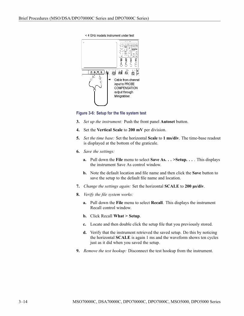
Brief Procedures (MSO/DSA/DPO70000C Series and DPO7000C Series)
Figure 3-6: Setup for the file system test
3. Set up the instrument: Push the front panel Autoset button.
4. Set the Vertical Scale to 200 mV per division.
5. Set the time base: Set the horizontal Scale to 1 ms/div. The time-base readoutis displayed at the bottom of the graticule.
6. Save the settings:
a. Pull down the File menu to select Save As. . . >Setup. . . . This displaysthe instrument Save As control window.
b. Note the default location and file name and then click the Save button tosave the setup to the default file name and location.
7. Change the settings again: Set the horizontal SCALE to 200 μs/div.
8. Verify the file system works:
a. Pull down the File menu to select Recall. This displays the instrumentRecall control window.
b. Click RecallWhat > Setup.
c. Locate and then double click the setup file that you previously stored.
d. Verify that the instrument retrieved the saved setup. Do this by noticingthe horizontal SCALE is again 1 ms and the waveform shows ten cyclesjust as it did when you saved the setup.
9. Remove the test hookup: Disconnect the test hookup from the instrument.
3–14 MSO70000C, DSA70000C, DPO70000C, DPO7000C, MSO5000, DPO5000 Series
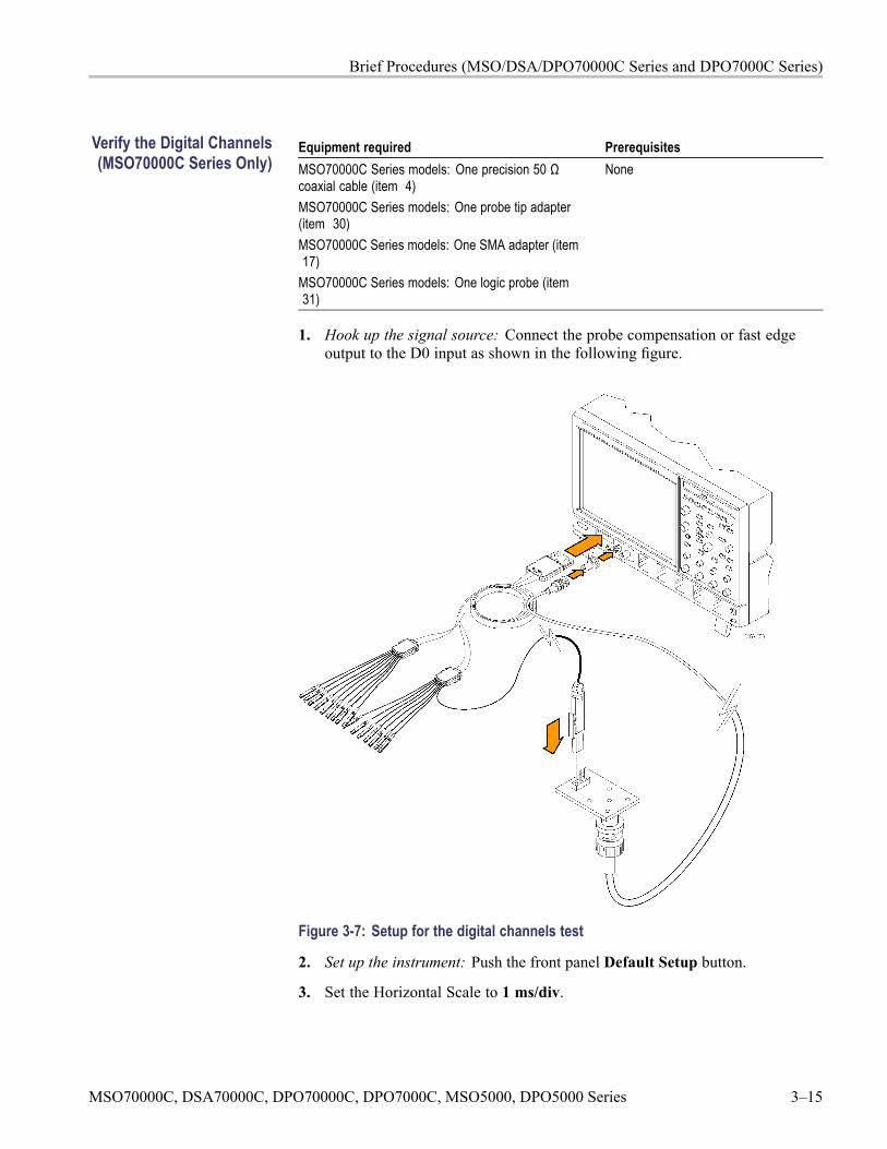
Brief Procedures (MSO/DSA/DPO70000C Series and DPO7000C Series)
Verify the Digital Channels(MSO70000C Series Only)
Equipment required PrerequisitesMSO70000C Series models: One precision 50 Ωcoaxial cable (item 4)MSO70000C Series models: One probe tip adapter(item 30)MSO70000C Series models: One SMA adapter (item17)
MSO70000C Series models: One logic probe (item31)
None
1. Hook up the signal source: Connect the probe compensation or fast edgeoutput to the D0 input as shown in the following figure.
Figure 3-7: Setup for the digital channels test
2. Set up the instrument: Push the front panel Default Setup button.
3. Set the Horizontal Scale to 1 ms/div.
MSO70000C, DSA70000C, DPO70000C, DPO7000C, MSO5000, DPO5000 Series 3–15
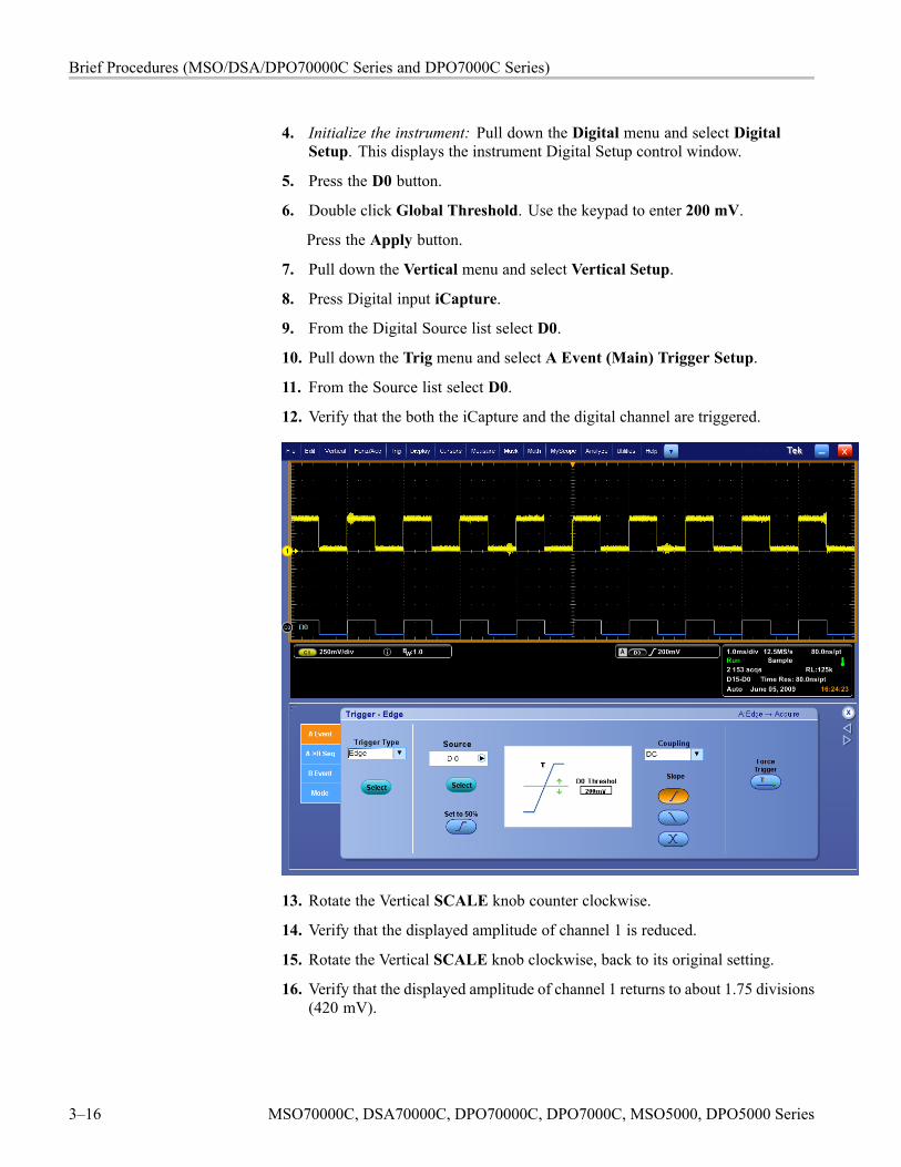
Brief Procedures (MSO/DSA/DPO70000C Series and DPO7000C Series)
4. Initialize the instrument: Pull down the Digital menu and select DigitalSetup. This displays the instrument Digital Setup control window.
5. Press the D0 button.
6. Double click Global Threshold. Use the keypad to enter 200 mV.
Press the Apply button.
7. Pull down the Vertical menu and select Vertical Setup.
8. Press Digital input iCapture.
9. From the Digital Source list select D0.
10. Pull down the Trig menu and select A Event (Main) Trigger Setup.
11. From the Source list select D0.
12. Verify that the both the iCapture and the digital channel are triggered.
13. Rotate the Vertical SCALE knob counter clockwise.
14. Verify that the displayed amplitude of channel 1 is reduced.
15. Rotate the Vertical SCALE knob clockwise, back to its original setting.
16. Verify that the displayed amplitude of channel 1 returns to about 1.75 divisions(420 mV).
3–16 MSO70000C, DSA70000C, DPO70000C, DPO7000C, MSO5000, DPO5000 Series
Brief Procedures (MSO/DSA/DPO70000C Series and DPO7000C Series)
17. Rotate the Vertical Position knob counter clockwise.
18. Verify that the displayed position of channel 1 moves lower on the display.
19. Rotate the Vertical Position knob clockwise, back to its original setting.
20. Pull down the Digital menu and select Digital Setup.
21. Double click the D0 Position and enter -1.66 and press Enter.
22. Verify that the displayed position of digital channel moves up on the display.
23. Repeat steps 1 through 22, replacing D0 with the digital channel number ofthe next channel you want to verify.
24. Remove the test hookup: Disconnect the test hookup from the instrument.
MSO70000C, DSA70000C, DPO70000C, DPO7000C, MSO5000, DPO5000 Series 3–17
Performance Tests (MSO/DSA/DPO70000C Series and DPO7000C Series)
Performance Tests (MSO/DSA/DPO70000C Series andDPO7000C Series)
This section contains a collection of manual procedures for checking that theinstrument performs as warranted.
The procedures are arranged in logical groupings: Signal Acquisition SystemChecks, Time Base System Checks, Triggering System Checks, Output PortsChecks, and Serial Trigger Checks. They check all the characteristics that aredesignated as checked in Specifications. (The characteristics that are checkedappear with a in Specifications).
STOP. These procedures extend the confidence level provided by the basicprocedures. The basic procedures should be done first, then these proceduresperformed if desired.
PrerequisitesThe tests in this section comprise an extensive, valid confirmation of performanceand functionality when the following requirements are met:
The cabinet must be installed on the instrument.
You must have performed and passed the procedures under Self Tests, andthose under Functional Tests. (See page 3-5, Functional Tests.)
A signal-path compensation must have been done within the recommendedcalibration interval and at a temperature within ±5 ºC (±9 ºF) of the presentoperating temperature. (If at the time you did the prerequisite Self Tests, thetemperature was within the limits just stated, consider this prerequisite met).A signal-path compensation must have been done at an ambient humiditywithin 25% of the current ambient humidity and after having been at thathumidity for at least 4 hours.
The instrument must have been last adjusted at an ambient temperaturebetween +18 ºC (+64 ºF) and +28 ºC (+82 ºF), must have been operating for awarm-up period of at least 20 minutes, and must be operating at an ambienttemperature as listed in the specifications. (See Table 1-10 on page 1-63.)(The warm-up requirement is usually met in the course of meeting the SelfTests and Functional Tests prerequisites listed above).
Support sensor, probe, and adapter setups to avoid stress or torque whenconnected to the device under test (DUT).
3–18 MSO70000C, DSA70000C, DPO70000C, DPO7000C, MSO5000, DPO5000 Series
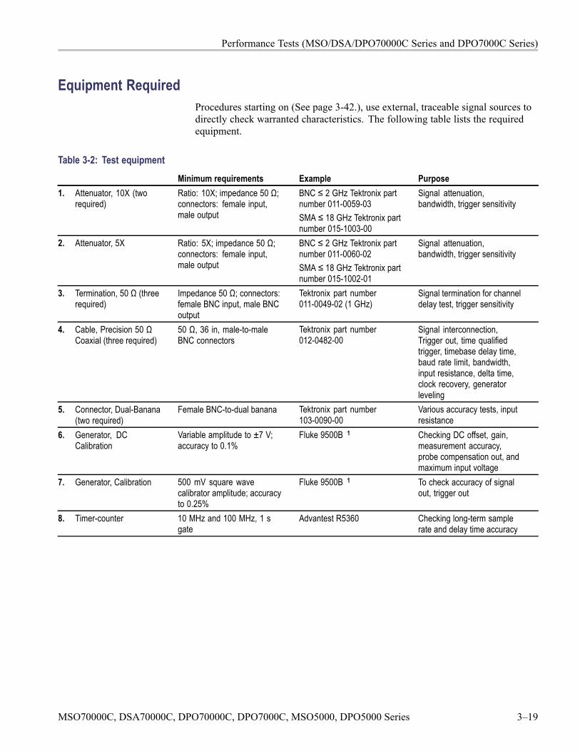
Performance Tests (MSO/DSA/DPO70000C Series and DPO7000C Series)
Equipment RequiredProcedures starting on (See page 3-42.), use external, traceable signal sources todirectly check warranted characteristics. The following table lists the requiredequipment.
Table 3-2: Test equipmentMinimum requirements Example Purpose
1. Attenuator, 10X (tworequired)
Ratio: 10X; impedance 50 Ω;connectors: female input,male output
BNC ≤ 2 GHz Tektronix partnumber 011-0059-03SMA ≤ 18 GHz Tektronix partnumber 015-1003-00
Signal attenuation,bandwidth, trigger sensitivity
2. Attenuator, 5X Ratio: 5X; impedance 50 Ω;connectors: female input,male output
BNC ≤ 2 GHz Tektronix partnumber 011-0060-02SMA ≤ 18 GHz Tektronix partnumber 015-1002-01
Signal attenuation,bandwidth, trigger sensitivity
3. Termination, 50 Ω (threerequired)
Impedance 50 Ω; connectors:female BNC input, male BNCoutput
Tektronix part number011-0049-02 (1 GHz)
Signal termination for channeldelay test, trigger sensitivity
4. Cable, Precision 50 ΩCoaxial (three required)
50 Ω, 36 in, male-to-maleBNC connectors
Tektronix part number012-0482-00
Signal interconnection,Trigger out, time qualifiedtrigger, timebase delay time,baud rate limit, bandwidth,input resistance, delta time,clock recovery, generatorleveling
5. Connector, Dual-Banana(two required)
Female BNC-to-dual banana Tektronix part number103-0090-00
Various accuracy tests, inputresistance
6. Generator, DCCalibration
Variable amplitude to ±7 V;accuracy to 0.1%
Fluke 9500B 1 Checking DC offset, gain,measurement accuracy,probe compensation out, andmaximum input voltage
7. Generator, Calibration 500 mV square wavecalibrator amplitude; accuracyto 0.25%
Fluke 9500B 1 To check accuracy of signalout, trigger out
8. Timer-counter 10 MHz and 100 MHz, 1 sgate
Advantest R5360 Checking long-term samplerate and delay time accuracy
MSO70000C, DSA70000C, DPO70000C, DPO7000C, MSO5000, DPO5000 Series 3–19
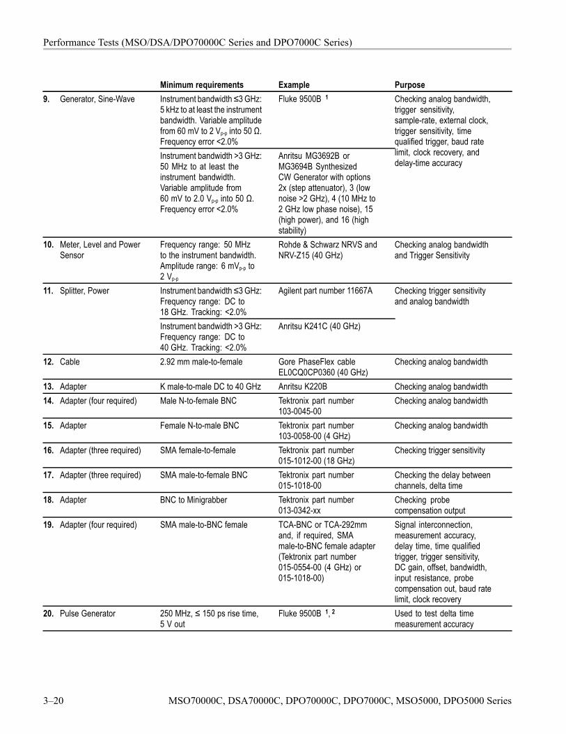
Performance Tests (MSO/DSA/DPO70000C Series and DPO7000C Series)
Minimum requirements Example PurposeInstrument bandwidth ≤3 GHz:5 kHz to at least the instrumentbandwidth. Variable amplitudefrom 60 mV to 2 Vp-p into 50 Ω.Frequency error <2.0%
Fluke 9500B 19. Generator, Sine-Wave
Instrument bandwidth >3 GHz:50 MHz to at least theinstrument bandwidth.Variable amplitude from60 mV to 2.0 Vp-p into 50 Ω.Frequency error <2.0%
Anritsu MG3692B orMG3694B SynthesizedCW Generator with options2x (step attenuator), 3 (lownoise >2 GHz), 4 (10 MHz to2 GHz low phase noise), 15(high power), and 16 (highstability)
Checking analog bandwidth,trigger sensitivity,sample-rate, external clock,trigger sensitivity, timequalified trigger, baud ratelimit, clock recovery, anddelay-time accuracy
10. Meter, Level and PowerSensor
Frequency range: 50 MHzto the instrument bandwidth.Amplitude range: 6 mVp-p to2 Vp-p
Rohde & Schwarz NRVS andNRV-Z15 (40 GHz)
Checking analog bandwidthand Trigger Sensitivity
Instrument bandwidth ≤3 GHz:Frequency range: DC to18 GHz. Tracking: <2.0%
Agilent part number 11667A11. Splitter, Power
Instrument bandwidth >3 GHz:Frequency range: DC to40 GHz. Tracking: <2.0%
Anritsu K241C (40 GHz)
Checking trigger sensitivityand analog bandwidth
12. Cable 2.92 mm male-to-female Gore PhaseFlex cableEL0CQ0CP0360 (40 GHz)
Checking analog bandwidth
13. Adapter K male-to-male DC to 40 GHz Anritsu K220B Checking analog bandwidth14. Adapter (four required) Male N-to-female BNC Tektronix part number
103-0045-00Checking analog bandwidth
15. Adapter Female N-to-male BNC Tektronix part number103-0058-00 (4 GHz)
Checking analog bandwidth
16. Adapter (three required) SMA female-to-female Tektronix part number015-1012-00 (18 GHz)
Checking trigger sensitivity
17. Adapter (three required) SMA male-to-female BNC Tektronix part number015-1018-00
Checking the delay betweenchannels, delta time
18. Adapter BNC to Minigrabber Tektronix part number013-0342-xx
Checking probecompensation output
19. Adapter (four required) SMA male-to-BNC female TCA-BNC or TCA-292mmand, if required, SMAmale-to-BNC female adapter(Tektronix part number015-0554-00 (4 GHz) or015-1018-00)
Signal interconnection,measurement accuracy,delay time, time qualifiedtrigger, trigger sensitivity,DC gain, offset, bandwidth,input resistance, probecompensation out, baud ratelimit, clock recovery
20. Pulse Generator 250 MHz, ≤ 150 ps rise time,5 V out
Fluke 9500B 1, 2 Used to test delta timemeasurement accuracy
3–20 MSO70000C, DSA70000C, DPO70000C, DPO7000C, MSO5000, DPO5000 Series
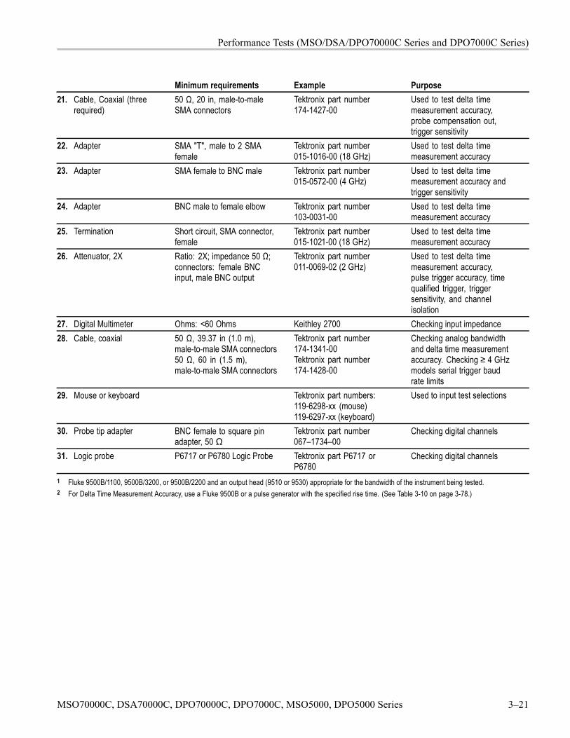
Performance Tests (MSO/DSA/DPO70000C Series and DPO7000C Series)
Minimum requirements Example Purpose21. Cable, Coaxial (three
required)50 Ω, 20 in, male-to-maleSMA connectors
Tektronix part number174-1427-00
Used to test delta timemeasurement accuracy,probe compensation out,trigger sensitivity
22. Adapter SMA "T", male to 2 SMAfemale
Tektronix part number015-1016-00 (18 GHz)
Used to test delta timemeasurement accuracy
23. Adapter SMA female to BNC male Tektronix part number015-0572-00 (4 GHz)
Used to test delta timemeasurement accuracy andtrigger sensitivity
24. Adapter BNC male to female elbow Tektronix part number103-0031-00
Used to test delta timemeasurement accuracy
25. Termination Short circuit, SMA connector,female
Tektronix part number015-1021-00 (18 GHz)
Used to test delta timemeasurement accuracy
26. Attenuator, 2X Ratio: 2X; impedance 50 Ω;connectors: female BNCinput, male BNC output
Tektronix part number011-0069-02 (2 GHz)
Used to test delta timemeasurement accuracy,pulse trigger accuracy, timequalified trigger, triggersensitivity, and channelisolation
27. Digital Multimeter Ohms: <60 Ohms Keithley 2700 Checking input impedance28. Cable, coaxial 50 Ω, 39.37 in (1.0 m),
male-to-male SMA connectors50 Ω, 60 in (1.5 m),male-to-male SMA connectors
Tektronix part number174-1341-00Tektronix part number174-1428-00
Checking analog bandwidthand delta time measurementaccuracy. Checking ≥ 4 GHzmodels serial trigger baudrate limits
29. Mouse or keyboard Tektronix part numbers:119-6298-xx (mouse)119-6297-xx (keyboard)
Used to input test selections
30. Probe tip adapter BNC female to square pinadapter, 50 Ω
Tektronix part number067–1734–00
Checking digital channels
31. Logic probe P6717 or P6780 Logic Probe Tektronix part P6717 orP6780
Checking digital channels
1 Fluke 9500B/1100, 9500B/3200, or 9500B/2200 and an output head (9510 or 9530) appropriate for the bandwidth of the instrument being tested.2 For Delta Time Measurement Accuracy, use a Fluke 9500B or a pulse generator with the specified rise time. (See Table 3-10 on page 3-78.)
MSO70000C, DSA70000C, DPO70000C, DPO7000C, MSO5000, DPO5000 Series 3–21
Performance Tests (MSO/DSA/DPO70000C Series and DPO7000C Series)
Test RecordPhotocopy this table and use it to record the performance test results for yourinstrument.
3–22 MSO70000C, DSA70000C, DPO70000C, DPO7000C, MSO5000, DPO5000 Series
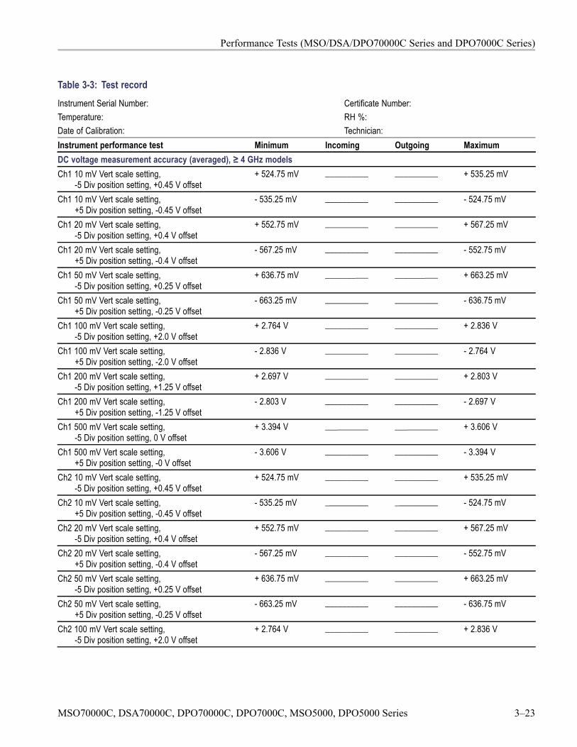
Performance Tests (MSO/DSA/DPO70000C Series and DPO7000C Series)
Table 3-3: Test recordInstrument Serial Number:Temperature:Date of Calibration:
Certificate Number:RH %:Technician:
Instrument performance test Minimum Incoming Outgoing MaximumDC voltage measurement accuracy (averaged), ≥ 4 GHz modelsCh1 10 mV Vert scale setting,
-5 Div position setting, +0.45 V offset+ 524.75 mV __________ __________ + 535.25 mV
Ch1 10 mV Vert scale setting,+5 Div position setting, -0.45 V offset
- 535.25 mV __________ __________ - 524.75 mV
Ch1 20 mV Vert scale setting,-5 Div position setting, +0.4 V offset
+ 552.75 mV __________ __________ + 567.25 mV
Ch1 20 mV Vert scale setting,+5 Div position setting, -0.4 V offset
- 567.25 mV __________ __________ - 552.75 mV
Ch1 50 mV Vert scale setting,-5 Div position setting, +0.25 V offset
+ 636.75 mV __________ __________ + 663.25 mV
Ch1 50 mV Vert scale setting,+5 Div position setting, -0.25 V offset
- 663.25 mV __________ __________ - 636.75 mV
Ch1 100 mV Vert scale setting,-5 Div position setting, +2.0 V offset
+ 2.764 V __________ __________ + 2.836 V
Ch1 100 mV Vert scale setting,+5 Div position setting, -2.0 V offset
- 2.836 V __________ __________ - 2.764 V
Ch1 200 mV Vert scale setting,-5 Div position setting, +1.25 V offset
+ 2.697 V __________ __________ + 2.803 V
Ch1 200 mV Vert scale setting,+5 Div position setting, -1.25 V offset
- 2.803 V __________ __________ - 2.697 V
Ch1 500 mV Vert scale setting,-5 Div position setting, 0 V offset
+ 3.394 V __________ __________ + 3.606 V
Ch1 500 mV Vert scale setting,+5 Div position setting, -0 V offset
- 3.606 V __________ __________ - 3.394 V
Ch2 10 mV Vert scale setting,-5 Div position setting, +0.45 V offset
+ 524.75 mV __________ __________ + 535.25 mV
Ch2 10 mV Vert scale setting,+5 Div position setting, -0.45 V offset
- 535.25 mV __________ __________ - 524.75 mV
Ch2 20 mV Vert scale setting,-5 Div position setting, +0.4 V offset
+ 552.75 mV __________ __________ + 567.25 mV
Ch2 20 mV Vert scale setting,+5 Div position setting, -0.4 V offset
- 567.25 mV __________ __________ - 552.75 mV
Ch2 50 mV Vert scale setting,-5 Div position setting, +0.25 V offset
+ 636.75 mV __________ __________ + 663.25 mV
Ch2 50 mV Vert scale setting,+5 Div position setting, -0.25 V offset
- 663.25 mV __________ __________ - 636.75 mV
Ch2 100 mV Vert scale setting,-5 Div position setting, +2.0 V offset
+ 2.764 V __________ __________ + 2.836 V
MSO70000C, DSA70000C, DPO70000C, DPO7000C, MSO5000, DPO5000 Series 3–23
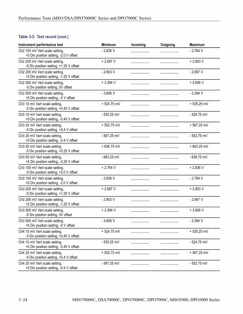
Performance Tests (MSO/DSA/DPO70000C Series and DPO7000C Series)
Table 3-3: Test record (cont.)
Instrument performance test Minimum Incoming Outgoing MaximumCh2 100 mV Vert scale setting,
+5 Div position setting, -2.0 V offset- 2.836 V __________ __________ - 2.764 V
Ch2 200 mV Vert scale setting,-5 Div position setting, +1.25 V offset
+ 2.697 V __________ __________ + 2.803 V
Ch2 200 mV Vert scale setting,+5 Div position setting, -1.25 V offset
- 2.803 V __________ __________ - 2.697 V
Ch2 500 mV Vert scale setting,-5 Div position setting, 0V offset
+ 3.394 V __________ __________ + 3.606 V
Ch2 500 mV Vert scale setting,+5 Div position setting, -0 V offset
- 3.606 V __________ __________ - 3.394 V
Ch3 10 mV Vert scale setting,-5 Div position setting, +0.45 V offset
+ 524.75 mV __________ __________ + 535.25 mV
Ch3 10 mV Vert scale setting,+5 Div position setting, -0.45 V offset
- 535.25 mV __________ __________ - 524.75 mV
Ch3 20 mV Vert scale setting,-5 Div position setting, +0.4 V offset
+ 552.75 mV __________ __________ + 567.25 mV
Ch3 20 mV Vert scale setting,+5 Div position setting, -0.4 V offset
- 567.25 mV __________ __________ - 552.75 mV
Ch3 50 mV Vert scale setting,-5 Div position setting, +0.25 V offset
+ 636.75 mV __________ __________ + 663.25 mV
Ch3 50 mV Vert scale setting,+5 Div position setting, -0.25 V offset
- 663.25 mV __________ __________ - 636.75 mV
Ch3 100 mV Vert scale setting,-5 Div position setting, +2.0 V offset
+ 2.764 V __________ __________ + 2.836 V
Ch3 100 mV Vert scale setting,+5 Div position setting, -2.0 V offset
- 2.836 V __________ __________ - 2.764 V
Ch3 200 mV Vert scale setting,-5 Div position setting, +1.25 V offset
+ 2.697 V __________ __________ + 2.803 V
Ch3 200 mV Vert scale setting,+5 Div position setting, -1.25 V offset
- 2.803 V __________ __________ - 2.697 V
Ch3 500 mV Vert scale setting,-5 Div position setting, 0V offset
+ 3.394 V __________ __________ + 3.606 V
Ch3 500 mV Vert scale setting,+5 Div position setting, -0 V offset
- 3.606 V __________ __________ - 3.394 V
Ch4 10 mV Vert scale setting,-5 Div position setting, +0.45 V offset
+ 524.75 mV __________ __________ + 535.25 mV
Ch4 10 mV Vert scale setting,+5 Div position setting, -0.45 V offset
- 535.25 mV __________ __________ - 524.75 mV
Ch4 20 mV Vert scale setting,-5 Div position setting, +0.4 V offset
+ 552.75 mV __________ __________ + 567.25 mV
Ch4 20 mV Vert scale setting,+5 Div position setting, -0.4 V offset
- 567.25 mV __________ __________ - 552.75 mV
3–24 MSO70000C, DSA70000C, DPO70000C, DPO7000C, MSO5000, DPO5000 Series
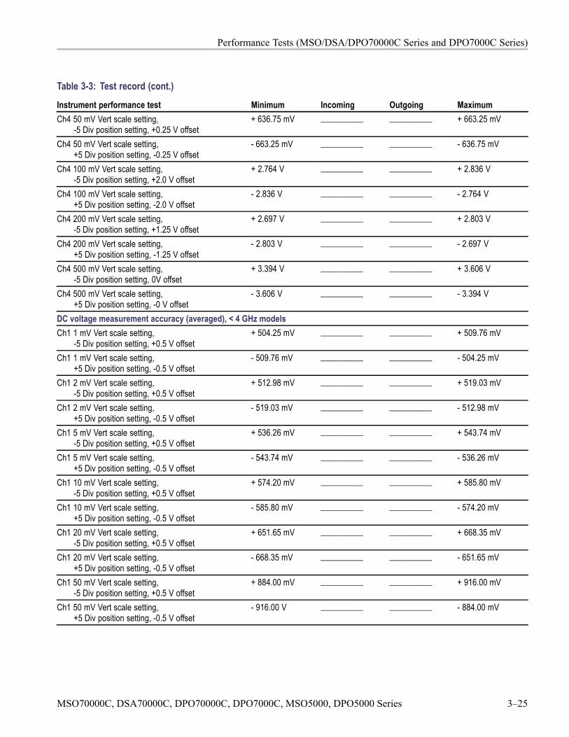
Performance Tests (MSO/DSA/DPO70000C Series and DPO7000C Series)
Table 3-3: Test record (cont.)
Instrument performance test Minimum Incoming Outgoing MaximumCh4 50 mV Vert scale setting,
-5 Div position setting, +0.25 V offset+ 636.75 mV __________ __________ + 663.25 mV
Ch4 50 mV Vert scale setting,+5 Div position setting, -0.25 V offset
- 663.25 mV __________ __________ - 636.75 mV
Ch4 100 mV Vert scale setting,-5 Div position setting, +2.0 V offset
+ 2.764 V __________ __________ + 2.836 V
Ch4 100 mV Vert scale setting,+5 Div position setting, -2.0 V offset
- 2.836 V __________ __________ - 2.764 V
Ch4 200 mV Vert scale setting,-5 Div position setting, +1.25 V offset
+ 2.697 V __________ __________ + 2.803 V
Ch4 200 mV Vert scale setting,+5 Div position setting, -1.25 V offset
- 2.803 V __________ __________ - 2.697 V
Ch4 500 mV Vert scale setting,-5 Div position setting, 0V offset
+ 3.394 V __________ __________ + 3.606 V
Ch4 500 mV Vert scale setting,+5 Div position setting, -0 V offset
- 3.606 V __________ __________ - 3.394 V
DC voltage measurement accuracy (averaged), < 4 GHz modelsCh1 1 mV Vert scale setting,
-5 Div position setting, +0.5 V offset+ 504.25 mV __________ __________ + 509.76 mV
Ch1 1 mV Vert scale setting,+5 Div position setting, -0.5 V offset
- 509.76 mV __________ __________ - 504.25 mV
Ch1 2 mV Vert scale setting,-5 Div position setting, +0.5 V offset
+ 512.98 mV __________ __________ + 519.03 mV
Ch1 2 mV Vert scale setting,+5 Div position setting, -0.5 V offset
- 519.03 mV __________ __________ - 512.98 mV
Ch1 5 mV Vert scale setting,-5 Div position setting, +0.5 V offset
+ 536.26 mV __________ __________ + 543.74 mV
Ch1 5 mV Vert scale setting,+5 Div position setting, -0.5 V offset
- 543.74 mV __________ __________ - 536.26 mV
Ch1 10 mV Vert scale setting,-5 Div position setting, +0.5 V offset
+ 574.20 mV __________ __________ + 585.80 mV
Ch1 10 mV Vert scale setting,+5 Div position setting, -0.5 V offset
- 585.80 mV __________ __________ - 574.20 mV
Ch1 20 mV Vert scale setting,-5 Div position setting, +0.5 V offset
+ 651.65 mV __________ __________ + 668.35 mV
Ch1 20 mV Vert scale setting,+5 Div position setting, -0.5 V offset
- 668.35 mV __________ __________ - 651.65 mV
Ch1 50 mV Vert scale setting,-5 Div position setting, +0.5 V offset
+ 884.00 mV __________ __________ + 916.00 mV
Ch1 50 mV Vert scale setting,+5 Div position setting, -0.5 V offset
- 916.00 V __________ __________ - 884.00 mV
MSO70000C, DSA70000C, DPO70000C, DPO7000C, MSO5000, DPO5000 Series 3–25
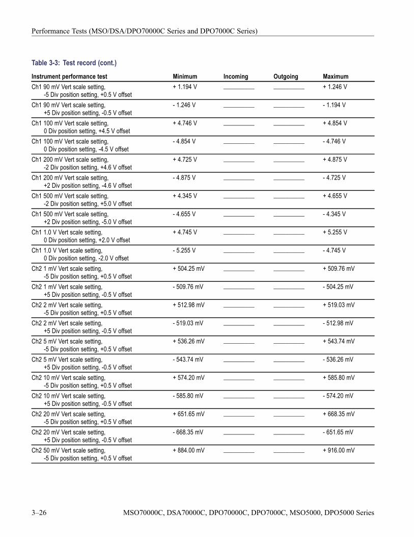
Performance Tests (MSO/DSA/DPO70000C Series and DPO7000C Series)
Table 3-3: Test record (cont.)
Instrument performance test Minimum Incoming Outgoing MaximumCh1 90 mV Vert scale setting,
-5 Div position setting, +0.5 V offset+ 1.194 V __________ __________ + 1.246 V
Ch1 90 mV Vert scale setting,+5 Div position setting, -0.5 V offset
- 1.246 V __________ __________ - 1.194 V
Ch1 100 mV Vert scale setting,0 Div position setting, +4.5 V offset
+ 4.746 V __________ __________ + 4.854 V
Ch1 100 mV Vert scale setting,0 Div position setting, -4.5 V offset
- 4.854 V __________ __________ - 4.746 V
Ch1 200 mV Vert scale setting,-2 Div position setting, +4.6 V offset
+ 4.725 V __________ __________ + 4.875 V
Ch1 200 mV Vert scale setting,+2 Div position setting, -4.6 V offset
- 4.875 V __________ __________ - 4.725 V
Ch1 500 mV Vert scale setting,-2 Div position setting, +5.0 V offset
+ 4.345 V __________ __________ + 4.655 V
Ch1 500 mV Vert scale setting,+2 Div position setting, -5.0 V offset
- 4.655 V __________ __________ - 4.345 V
Ch1 1.0 V Vert scale setting,0 Div position setting, +2.0 V offset
+ 4.745 V __________ __________ + 5.255 V
Ch1 1.0 V Vert scale setting,0 Div position setting, -2.0 V offset
- 5.255 V __________ __________ - 4.745 V
Ch2 1 mV Vert scale setting,-5 Div position setting, +0.5 V offset
+ 504.25 mV __________ __________ + 509.76 mV
Ch2 1 mV Vert scale setting,+5 Div position setting, -0.5 V offset
- 509.76 mV __________ __________ - 504.25 mV
Ch2 2 mV Vert scale setting,-5 Div position setting, +0.5 V offset
+ 512.98 mV __________ __________ + 519.03 mV
Ch2 2 mV Vert scale setting,+5 Div position setting, -0.5 V offset
- 519.03 mV __________ __________ - 512.98 mV
Ch2 5 mV Vert scale setting,-5 Div position setting, +0.5 V offset
+ 536.26 mV __________ __________ + 543.74 mV
Ch2 5 mV Vert scale setting,+5 Div position setting, -0.5 V offset
- 543.74 mV __________ __________ - 536.26 mV
Ch2 10 mV Vert scale setting,-5 Div position setting, +0.5 V offset
+ 574.20 mV __________ __________ + 585.80 mV
Ch2 10 mV Vert scale setting,+5 Div position setting, -0.5 V offset
- 585.80 mV __________ __________ - 574.20 mV
Ch2 20 mV Vert scale setting,-5 Div position setting, +0.5 V offset
+ 651.65 mV __________ __________ + 668.35 mV
Ch2 20 mV Vert scale setting,+5 Div position setting, -0.5 V offset
- 668.35 mV __________ __________ - 651.65 mV
Ch2 50 mV Vert scale setting,-5 Div position setting, +0.5 V offset
+ 884.00 mV __________ __________ + 916.00 mV
3–26 MSO70000C, DSA70000C, DPO70000C, DPO7000C, MSO5000, DPO5000 Series
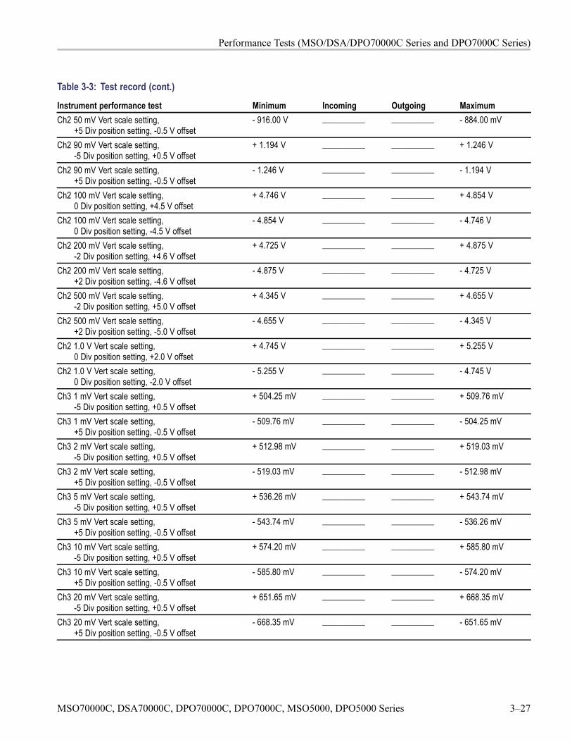
Performance Tests (MSO/DSA/DPO70000C Series and DPO7000C Series)
Table 3-3: Test record (cont.)
Instrument performance test Minimum Incoming Outgoing MaximumCh2 50 mV Vert scale setting,
+5 Div position setting, -0.5 V offset- 916.00 V __________ __________ - 884.00 mV
Ch2 90 mV Vert scale setting,-5 Div position setting, +0.5 V offset
+ 1.194 V __________ __________ + 1.246 V
Ch2 90 mV Vert scale setting,+5 Div position setting, -0.5 V offset
- 1.246 V __________ __________ - 1.194 V
Ch2 100 mV Vert scale setting,0 Div position setting, +4.5 V offset
+ 4.746 V __________ __________ + 4.854 V
Ch2 100 mV Vert scale setting,0 Div position setting, -4.5 V offset
- 4.854 V __________ __________ - 4.746 V
Ch2 200 mV Vert scale setting,-2 Div position setting, +4.6 V offset
+ 4.725 V __________ __________ + 4.875 V
Ch2 200 mV Vert scale setting,+2 Div position setting, -4.6 V offset
- 4.875 V __________ __________ - 4.725 V
Ch2 500 mV Vert scale setting,-2 Div position setting, +5.0 V offset
+ 4.345 V __________ __________ + 4.655 V
Ch2 500 mV Vert scale setting,+2 Div position setting, -5.0 V offset
- 4.655 V __________ __________ - 4.345 V
Ch2 1.0 V Vert scale setting,0 Div position setting, +2.0 V offset
+ 4.745 V __________ __________ + 5.255 V
Ch2 1.0 V Vert scale setting,0 Div position setting, -2.0 V offset
- 5.255 V __________ __________ - 4.745 V
Ch3 1 mV Vert scale setting,-5 Div position setting, +0.5 V offset
+ 504.25 mV __________ __________ + 509.76 mV
Ch3 1 mV Vert scale setting,+5 Div position setting, -0.5 V offset
- 509.76 mV __________ __________ - 504.25 mV
Ch3 2 mV Vert scale setting,-5 Div position setting, +0.5 V offset
+ 512.98 mV __________ __________ + 519.03 mV
Ch3 2 mV Vert scale setting,+5 Div position setting, -0.5 V offset
- 519.03 mV __________ __________ - 512.98 mV
Ch3 5 mV Vert scale setting,-5 Div position setting, +0.5 V offset
+ 536.26 mV __________ __________ + 543.74 mV
Ch3 5 mV Vert scale setting,+5 Div position setting, -0.5 V offset
- 543.74 mV __________ __________ - 536.26 mV
Ch3 10 mV Vert scale setting,-5 Div position setting, +0.5 V offset
+ 574.20 mV __________ __________ + 585.80 mV
Ch3 10 mV Vert scale setting,+5 Div position setting, -0.5 V offset
- 585.80 mV __________ __________ - 574.20 mV
Ch3 20 mV Vert scale setting,-5 Div position setting, +0.5 V offset
+ 651.65 mV __________ __________ + 668.35 mV
Ch3 20 mV Vert scale setting,+5 Div position setting, -0.5 V offset
- 668.35 mV __________ __________ - 651.65 mV
MSO70000C, DSA70000C, DPO70000C, DPO7000C, MSO5000, DPO5000 Series 3–27

Performance Tests (MSO/DSA/DPO70000C Series and DPO7000C Series)
Table 3-3: Test record (cont.)
Instrument performance test Minimum Incoming Outgoing MaximumCh3 50 mV Vert scale setting,
-5 Div position setting, +0.5 V offset+ 884.00 mV __________ __________ + 916.00 mV
Ch3 50 mV Vert scale setting,+5 Div position setting, -0.5 V offset
- 916.00 V __________ __________ - 884.00 mV
Ch3 90 mV Vert scale setting,-5 Div position setting, +0.5 V offset
+ 1.194 V __________ __________ + 1.246 V
Ch3 90 mV Vert scale setting,+5 Div position setting, -0.5 V offset
- 1.246 V __________ __________ - 1.194 V
Ch3 100 mV Vert scale setting,0 Div position setting, +4.5 V offset
+ 4.746 V __________ __________ + 4.854 V
Ch3 100 mV Vert scale setting,0 Div position setting, -4.5 V offset
- 4.854 V __________ __________ - 4.746 V
Ch3 200 mV Vert scale setting,-2 Div position setting, +4.6 V offset
+ 4.725 V __________ __________ + 4.875 V
Ch3 200 mV Vert scale setting,+2 Div position setting, -4.6 V offset
- 4.875 V __________ __________ - 4.725 V
Ch3 500 mV Vert scale setting,-2 Div position setting, +5.0 V offset
+ 4.345 V __________ __________ + 4.655 V
Ch3 500 mV Vert scale setting,+2 Div position setting, -5.0 V offset
- 4.655 V __________ __________ - 4.345 V
Ch3 1.0 V Vert scale setting,0 Div position setting, +2.0 V offset
+ 4.745 V __________ __________ + 5.255 V
Ch3 1.0 V Vert scale setting,0 Div position setting, -2.0 V offset
- 5.255 V __________ __________ - 4.745 V
Ch4 1 mV Vert scale setting,-5 Div position setting, +0.5 V offset
+ 504.25 mV __________ __________ + 509.76 mV
Ch4 1 mV Vert scale setting,+5 Div position setting, -0.5 V offset
- 509.76 mV __________ __________ - 504.25 mV
Ch4 2 mV Vert scale setting,-5 Div position setting, +0.5 V offset
+ 512.98 mV __________ __________ + 519.03 mV
Ch4 2 mV Vert scale setting,+5 Div position setting, -0.5 V offset
- 519.03 mV __________ __________ - 512.98 mV
Ch4 5 mV Vert scale setting,-5 Div position setting, +0.5 V offset
+ 536.26 mV __________ __________ + 543.74 mV
Ch4 5 mV Vert scale setting,+5 Div position setting, -0.5 V offset
- 543.74 mV __________ __________ - 536.26 mV
Ch4 10 mV Vert scale setting,-5 Div position setting, +0.5 V offset
+ 574.20 mV __________ __________ + 585.80 mV
Ch4 10 mV Vert scale setting,+5 Div position setting, -0.5 V offset
- 585.80 mV __________ __________ - 574.20 mV
Ch4 20 mV Vert scale setting,-5 Div position setting, +0.5 V offset
+ 651.65 mV __________ __________ + 668.35 mV
3–28 MSO70000C, DSA70000C, DPO70000C, DPO7000C, MSO5000, DPO5000 Series

Performance Tests (MSO/DSA/DPO70000C Series and DPO7000C Series)
Table 3-3: Test record (cont.)
Instrument performance test Minimum Incoming Outgoing MaximumCh4 20 mV Vert scale setting,
+5 Div position setting, -0.5 V offset- 668.35 mV __________ __________ - 651.65 mV
Ch4 50 mV Vert scale setting,-5 Div position setting, +0.5 V offset
+ 884.00 mV __________ __________ + 916.00 mV
Ch4 50 mV Vert scale setting,+5 Div position setting, -0.5 V offset
- 916.00 V __________ __________ - 884.00 mV
Ch4 90 mV Vert scale setting,-5 Div position setting, +0.5 V offset
+ 1.194 V __________ __________ + 1.246 V
Ch4 90 mV Vert scale setting,+5 Div position setting, -0.5 V offset
- 1.246 V __________ __________ - 1.194 V
Ch4 100 mV Vert scale setting,0 Div position setting, +4.5 V offset
+ 4.746 V __________ __________ + 4.854 V
Ch4 100 mV Vert scale setting,0 Div position setting, -4.5 V offset
- 4.854 V __________ __________ - 4.746 V
Ch4 200 mV Vert scale setting,-2 Div position setting, +4.6 V offset
+ 4.725 V __________ __________ + 4.875 V
Ch4 200 mV Vert scale setting,+2 Div position setting, -4.6 V offset
- 4.875 V __________ __________ - 4.725 V
Ch4 500 mV Vert scale setting,-2 Div position setting, +5.0 V offset
+ 4.345 V __________ __________ + 4.655 V
Ch4 500 mV Vert scale setting,+2 Div position setting, -5.0 V offset
- 4.655 V __________ __________ - 4.345 V
Ch4 1.0 V Vert scale setting,0 Div position setting, +2.0 V offset
+ 4.745 V __________ __________ + 5.255 V
Ch4 1.0 V Vert scale setting,0 Div position setting, -2.0 V offset
- 5.255 V __________ __________ - 4.745 V
DC gain accuracy (averaged), ≥ 4 GHz modelsCh1 10 mV Vert scale setting,
0 Div position setting, 0 V offset-5 Div position setting, +0.45 V offset+5 Div position setting, -0.45 V offset
+ 74.48 mV+ 74.48 mV+ 74.48 mV
______________________________
______________________________
+ 77.52 mV+ 77.52 mV+ 77.52 mV
Ch1 20 mV Vert scale setting,0 Div position setting, 0 V offset-5 Div position setting, +0.4 V offset+5 Div position setting, -0.4 V offset
+ 148.96 mV+ 148.96 mV+ 148.96 mV
______________________________
______________________________
+ 155.04 mV+ 155.04 mV+ 155.04 mV
Ch1 50 mV Vert scale setting,0 Div position setting, 0 V offset-5 Div position setting, +0.25 V offset+5 Div position setting, -0.25 V offset
+ 372.40 mV+ 372.40 mV+ 372.40 mV
______________________________
______________________________
+ 387.60 mV+ 387.60 mV+ 387.60 mV
Ch1 100 mV Vert scale setting,0 Div position setting, 0 V offset-5 Div position setting, +2.0 V offset+5 Div position setting, -2.0 V offset
+ 744.80 mV+ 744.80 mV+ 744.80 mV
______________________________
______________________________
+ 775.20 mV+ 775.20 mV+ 775.20 mV
MSO70000C, DSA70000C, DPO70000C, DPO7000C, MSO5000, DPO5000 Series 3–29
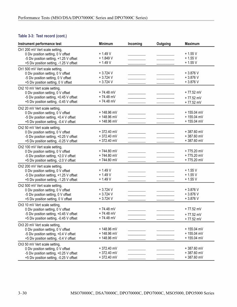
Performance Tests (MSO/DSA/DPO70000C Series and DPO7000C Series)
Table 3-3: Test record (cont.)
Instrument performance test Minimum Incoming Outgoing MaximumCh1 200 mV Vert scale setting,
0 Div position setting, 0 V offset-5 Div position setting, +1.25 V offset+5 Div position setting, -1.25 V offset
+ 1.49 V+ 1.849 V+ 1.49 V
______________________________
______________________________
+ 1.55 V+ 1.55 V+ 1.55 V
Ch1 500 mV Vert scale setting,0 Div position setting, 0 V offset-5 Div position setting, 0 V offset+5 Div position setting, 0 V offset
+ 3.724 V+ 3.724 V+ 3.724 V
______________________________
______________________________
+ 3.876 V+ 3.876 V+ 3.876 V
Ch2 10 mV Vert scale setting,0 Div position setting, 0 V offset-5 Div position setting, +0.45 V offset+5 Div position setting, -0.45 V offset
+ 74.48 mV+ 74.48 mV+ 74.48 mV
______________________________
______________________________
+ 77.52 mV+ 77.52 mV+ 77.52 mV
Ch2 20 mV Vert scale setting,0 Div position setting, 0 V offset-5 Div position setting, +0.4 V offset+5 Div position setting, -0.4 V offset
+ 148.96 mV+ 148.96 mV+ 148.96 mV
______________________________
______________________________
+ 155.04 mV+ 155.04 mV+ 155.04 mV
Ch2 50 mV Vert scale setting,0 Div position setting, 0 V offset-5 Div position setting, +0.25 V offset+5 Div position setting, -0.25 V offset
+ 372.40 mV+ 372.40 mV+ 372.40 mV
______________________________
______________________________
+ 387.60 mV+ 387.60 mV+ 387.60 mV
Ch2 100 mV Vert scale setting,0 Div position setting, 0 V offset-5 Div position setting, +2.0 V offset+5 Div position setting, -2.0 V offset
+ 744.80 mV+ 744.80 mV+ 744.80 mV
______________________________
______________________________
+ 775.20 mV+ 775.20 mV+ 775.20 mV
Ch2 200 mV Vert scale setting,0 Div position setting, 0 V offset-5 Div position setting, +1.25 V offset+5 Div position setting, -1.25 V offset
+ 1.49 V+ 1.49 V+ 1.49 V
______________________________
______________________________
+ 1.55 V+ 1.55 V+ 1.55 V
Ch2 500 mV Vert scale setting,0 Div position setting, 0 V offset-5 Div position setting, 0 V offset+5 Div position setting, 0 V offset
+ 3.724 V+ 3.724 V+ 3.724 V
______________________________
______________________________
+ 3.876 V+ 3.876 V+ 3.876 V
Ch3 10 mV Vert scale setting,0 Div position setting, 0 V offset-5 Div position setting, +0.45 V offset+5 Div position setting, -0.45 V offset
+ 74.48 mV+ 74.48 mV+ 74.48 mV
______________________________
______________________________
+ 77.52 mV+ 77.52 mV+ 77.52 mV
Ch3 20 mV Vert scale setting,0 Div position setting, 0 V offset-5 Div position setting, +0.4 V offset+5 Div position setting, -0.4 V offset
+ 148.96 mV+ 148.96 mV+ 148.96 mV
______________________________
______________________________
+ 155.04 mV+ 155.04 mV+ 155.04 mV
Ch3 50 mV Vert scale setting,0 Div position setting, 0 V offset-5 Div position setting, +0.25 V offset+5 Div position setting, -0.25 V offset
+ 372.40 mV+ 372.40 mV+ 372.40 mV
______________________________
______________________________
+ 387.60 mV+ 387.60 mV+ 387.60 mV
3–30 MSO70000C, DSA70000C, DPO70000C, DPO7000C, MSO5000, DPO5000 Series
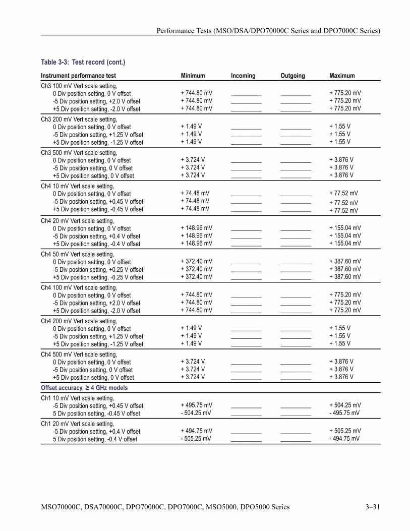
Performance Tests (MSO/DSA/DPO70000C Series and DPO7000C Series)
Table 3-3: Test record (cont.)
Instrument performance test Minimum Incoming Outgoing MaximumCh3 100 mV Vert scale setting,
0 Div position setting, 0 V offset-5 Div position setting, +2.0 V offset+5 Div position setting, -2.0 V offset
+ 744.80 mV+ 744.80 mV+ 744.80 mV
______________________________
______________________________
+ 775.20 mV+ 775.20 mV+ 775.20 mV
Ch3 200 mV Vert scale setting,0 Div position setting, 0 V offset-5 Div position setting, +1.25 V offset+5 Div position setting, -1.25 V offset
+ 1.49 V+ 1.49 V+ 1.49 V
______________________________
______________________________
+ 1.55 V+ 1.55 V+ 1.55 V
Ch3 500 mV Vert scale setting,0 Div position setting, 0 V offset-5 Div position setting, 0 V offset+5 Div position setting, 0 V offset
+ 3.724 V+ 3.724 V+ 3.724 V
______________________________
______________________________
+ 3.876 V+ 3.876 V+ 3.876 V
Ch4 10 mV Vert scale setting,0 Div position setting, 0 V offset-5 Div position setting, +0.45 V offset+5 Div position setting, -0.45 V offset
+ 74.48 mV+ 74.48 mV+ 74.48 mV
______________________________
______________________________
+ 77.52 mV+ 77.52 mV+ 77.52 mV
Ch4 20 mV Vert scale setting,0 Div position setting, 0 V offset-5 Div position setting, +0.4 V offset+5 Div position setting, -0.4 V offset
+ 148.96 mV+ 148.96 mV+ 148.96 mV
______________________________
______________________________
+ 155.04 mV+ 155.04 mV+ 155.04 mV
Ch4 50 mV Vert scale setting,0 Div position setting, 0 V offset-5 Div position setting, +0.25 V offset+5 Div position setting, -0.25 V offset
+ 372.40 mV+ 372.40 mV+ 372.40 mV
______________________________
______________________________
+ 387.60 mV+ 387.60 mV+ 387.60 mV
Ch4 100 mV Vert scale setting,0 Div position setting, 0 V offset-5 Div position setting, +2.0 V offset+5 Div position setting, -2.0 V offset
+ 744.80 mV+ 744.80 mV+ 744.80 mV
______________________________
______________________________
+ 775.20 mV+ 775.20 mV+ 775.20 mV
Ch4 200 mV Vert scale setting,0 Div position setting, 0 V offset-5 Div position setting, +1.25 V offset+5 Div position setting, -1.25 V offset
+ 1.49 V+ 1.49 V+ 1.49 V
______________________________
______________________________
+ 1.55 V+ 1.55 V+ 1.55 V
Ch4 500 mV Vert scale setting,0 Div position setting, 0 V offset-5 Div position setting, 0 V offset+5 Div position setting, 0 V offset
+ 3.724 V+ 3.724 V+ 3.724 V
______________________________
______________________________
+ 3.876 V+ 3.876 V+ 3.876 V
Offset accuracy, ≥ 4 GHz modelsCh1 10 mV Vert scale setting,
-5 Div position setting, +0.45 V offset5 Div position setting, -0.45 V offset
+ 495.75 mV- 504.25 mV
____________________
____________________
+ 504.25 mV- 495.75 mV
Ch1 20 mV Vert scale setting,-5 Div position setting, +0.4 V offset5 Div position setting, -0.4 V offset
+ 494.75 mV- 505.25 mV
____________________
____________________
+ 505.25 mV- 494.75 mV
MSO70000C, DSA70000C, DPO70000C, DPO7000C, MSO5000, DPO5000 Series 3–31
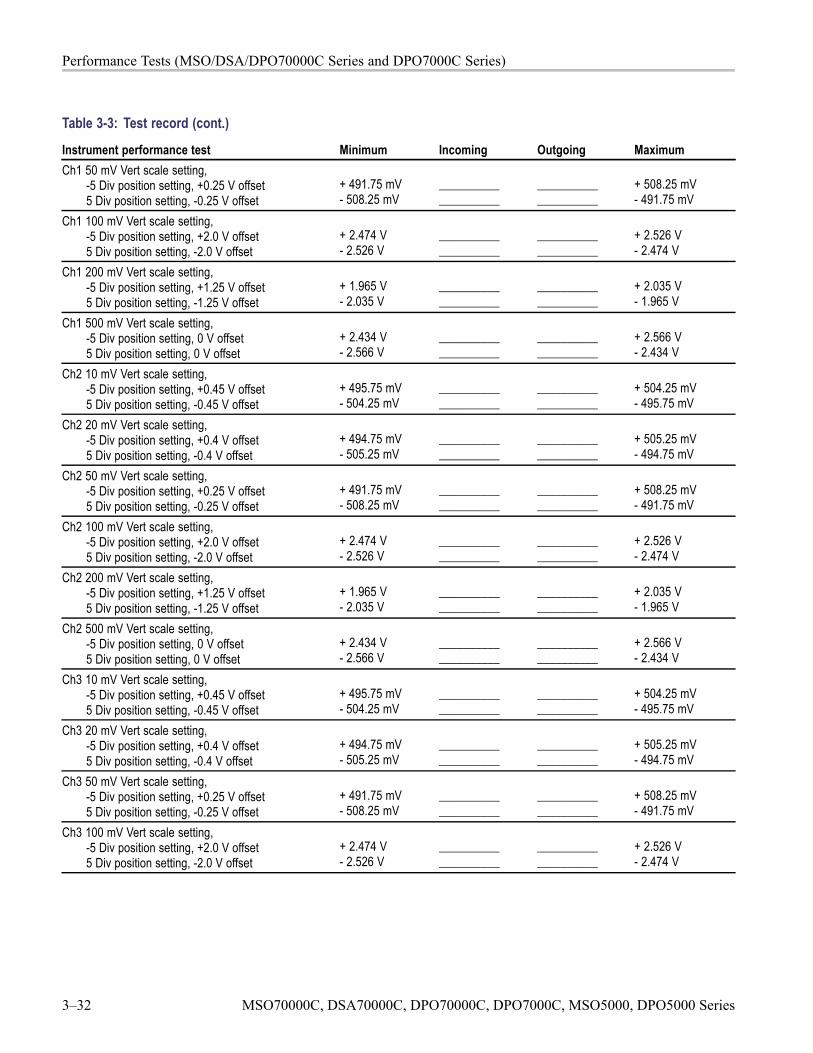
Performance Tests (MSO/DSA/DPO70000C Series and DPO7000C Series)
Table 3-3: Test record (cont.)
Instrument performance test Minimum Incoming Outgoing MaximumCh1 50 mV Vert scale setting,
-5 Div position setting, +0.25 V offset5 Div position setting, -0.25 V offset
+ 491.75 mV- 508.25 mV
____________________
____________________
+ 508.25 mV- 491.75 mV
Ch1 100 mV Vert scale setting,-5 Div position setting, +2.0 V offset5 Div position setting, -2.0 V offset
+ 2.474 V- 2.526 V
____________________
____________________
+ 2.526 V- 2.474 V
Ch1 200 mV Vert scale setting,-5 Div position setting, +1.25 V offset5 Div position setting, -1.25 V offset
+ 1.965 V- 2.035 V
____________________
____________________
+ 2.035 V- 1.965 V
Ch1 500 mV Vert scale setting,-5 Div position setting, 0 V offset5 Div position setting, 0 V offset
+ 2.434 V- 2.566 V
____________________
____________________
+ 2.566 V- 2.434 V
Ch2 10 mV Vert scale setting,-5 Div position setting, +0.45 V offset5 Div position setting, -0.45 V offset
+ 495.75 mV- 504.25 mV
____________________
____________________
+ 504.25 mV- 495.75 mV
Ch2 20 mV Vert scale setting,-5 Div position setting, +0.4 V offset5 Div position setting, -0.4 V offset
+ 494.75 mV- 505.25 mV
____________________
____________________
+ 505.25 mV- 494.75 mV
Ch2 50 mV Vert scale setting,-5 Div position setting, +0.25 V offset5 Div position setting, -0.25 V offset
+ 491.75 mV- 508.25 mV
____________________
____________________
+ 508.25 mV- 491.75 mV
Ch2 100 mV Vert scale setting,-5 Div position setting, +2.0 V offset5 Div position setting, -2.0 V offset
+ 2.474 V- 2.526 V
____________________
____________________
+ 2.526 V- 2.474 V
Ch2 200 mV Vert scale setting,-5 Div position setting, +1.25 V offset5 Div position setting, -1.25 V offset
+ 1.965 V- 2.035 V
____________________
____________________
+ 2.035 V- 1.965 V
Ch2 500 mV Vert scale setting,-5 Div position setting, 0 V offset5 Div position setting, 0 V offset
+ 2.434 V- 2.566 V
____________________
____________________
+ 2.566 V- 2.434 V
Ch3 10 mV Vert scale setting,-5 Div position setting, +0.45 V offset5 Div position setting, -0.45 V offset
+ 495.75 mV- 504.25 mV
____________________
____________________
+ 504.25 mV- 495.75 mV
Ch3 20 mV Vert scale setting,-5 Div position setting, +0.4 V offset5 Div position setting, -0.4 V offset
+ 494.75 mV- 505.25 mV
____________________
____________________
+ 505.25 mV- 494.75 mV
Ch3 50 mV Vert scale setting,-5 Div position setting, +0.25 V offset5 Div position setting, -0.25 V offset
+ 491.75 mV- 508.25 mV
____________________
____________________
+ 508.25 mV- 491.75 mV
Ch3 100 mV Vert scale setting,-5 Div position setting, +2.0 V offset5 Div position setting, -2.0 V offset
+ 2.474 V- 2.526 V
____________________
____________________
+ 2.526 V- 2.474 V
3–32 MSO70000C, DSA70000C, DPO70000C, DPO7000C, MSO5000, DPO5000 Series
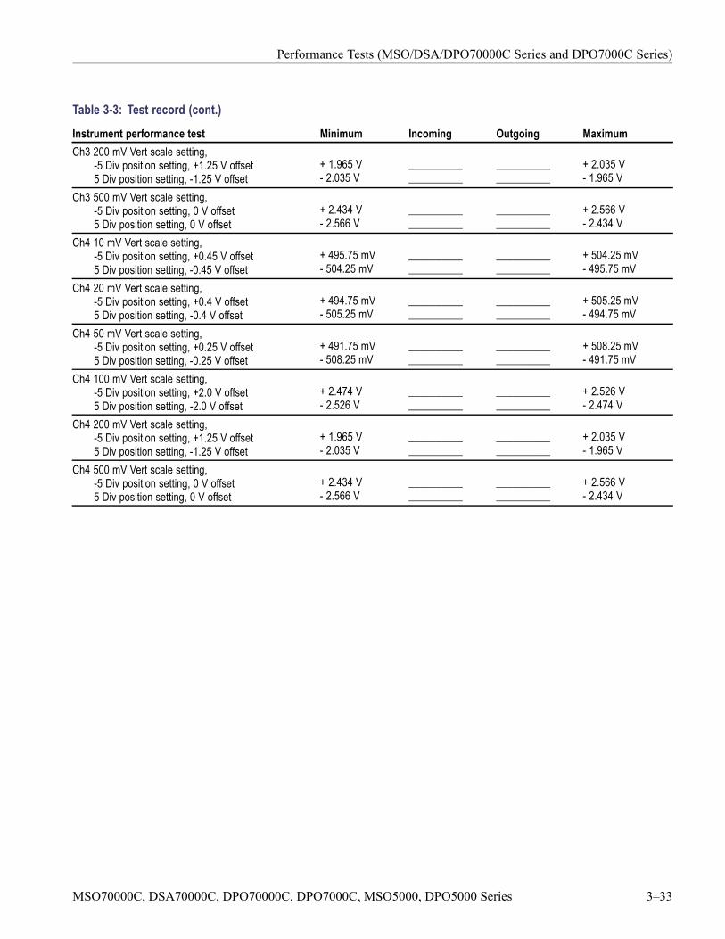
Performance Tests (MSO/DSA/DPO70000C Series and DPO7000C Series)
Table 3-3: Test record (cont.)
Instrument performance test Minimum Incoming Outgoing MaximumCh3 200 mV Vert scale setting,
-5 Div position setting, +1.25 V offset5 Div position setting, -1.25 V offset
+ 1.965 V- 2.035 V
____________________
____________________
+ 2.035 V- 1.965 V
Ch3 500 mV Vert scale setting,-5 Div position setting, 0 V offset5 Div position setting, 0 V offset
+ 2.434 V- 2.566 V
____________________
____________________
+ 2.566 V- 2.434 V
Ch4 10 mV Vert scale setting,-5 Div position setting, +0.45 V offset5 Div position setting, -0.45 V offset
+ 495.75 mV- 504.25 mV
____________________
____________________
+ 504.25 mV- 495.75 mV
Ch4 20 mV Vert scale setting,-5 Div position setting, +0.4 V offset5 Div position setting, -0.4 V offset
+ 494.75 mV- 505.25 mV
____________________
____________________
+ 505.25 mV- 494.75 mV
Ch4 50 mV Vert scale setting,-5 Div position setting, +0.25 V offset5 Div position setting, -0.25 V offset
+ 491.75 mV- 508.25 mV
____________________
____________________
+ 508.25 mV- 491.75 mV
Ch4 100 mV Vert scale setting,-5 Div position setting, +2.0 V offset5 Div position setting, -2.0 V offset
+ 2.474 V- 2.526 V
____________________
____________________
+ 2.526 V- 2.474 V
Ch4 200 mV Vert scale setting,-5 Div position setting, +1.25 V offset5 Div position setting, -1.25 V offset
+ 1.965 V- 2.035 V
____________________
____________________
+ 2.035 V- 1.965 V
Ch4 500 mV Vert scale setting,-5 Div position setting, 0 V offset5 Div position setting, 0 V offset
+ 2.434 V- 2.566 V
____________________
____________________
+ 2.566 V- 2.434 V
MSO70000C, DSA70000C, DPO70000C, DPO7000C, MSO5000, DPO5000 Series 3–33
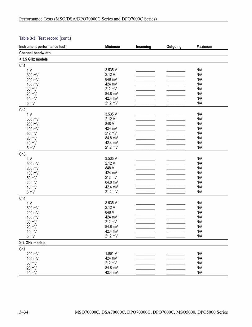
Performance Tests (MSO/DSA/DPO70000C Series and DPO7000C Series)
Table 3-3: Test record (cont.)
Instrument performance test Minimum Incoming Outgoing MaximumChannel bandwidth< 3.5 GHz modelsCh1
1 V500 mV200 mV100 mV50 mV20 mV10 mV5 mV
3.535 V2.12 V848 mV424 mV212 mV84.8 mV42.4 mV21.2 mV
________________________________________________________________________________
________________________________________________________________________________
N/AN/AN/AN/AN/AN/AN/AN/A
Ch21 V500 mV200 mV100 mV50 mV20 mV10 mV5 mV
3.535 V2.12 V848 V424 mV212 mV84.8 mV42.4 mV21.2 mV
________________________________________________________________________________
________________________________________________________________________________
N/AN/AN/AN/AN/AN/AN/AN/A
Ch31 V500 mV200 mV100 mV50 mV20 mV10 mV5 mV
3.535 V2.12 V848 V424 mV212 mV84.8 mV42.4 mV21.2 mV
________________________________________________________________________________
________________________________________________________________________________
N/AN/AN/AN/AN/AN/AN/AN/A
Ch41 V500 mV200 mV100 mV50 mV20 mV10 mV5 mV
3.535 V2.12 V848 V424 mV212 mV84.8 mV42.4 mV21.2 mV
________________________________________________________________________________
________________________________________________________________________________
N/AN/AN/AN/AN/AN/AN/AN/A
≥ 4 GHz modelsCh1
200 mV100 mV50 mV20 mV10 mV
1.061 V424 mV212 mV84.8 mV42.4 mV
__________________________________________________
__________________________________________________
N/AN/AN/AN/AN/A
3–34 MSO70000C, DSA70000C, DPO70000C, DPO7000C, MSO5000, DPO5000 Series
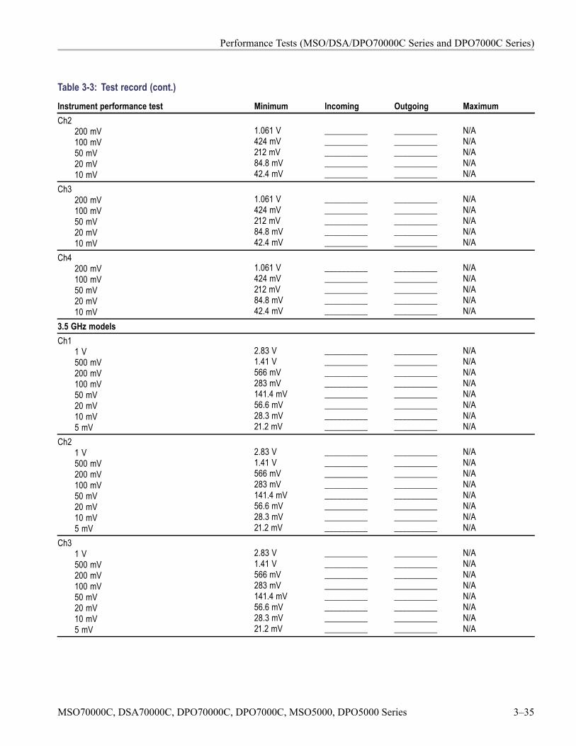
Performance Tests (MSO/DSA/DPO70000C Series and DPO7000C Series)
Table 3-3: Test record (cont.)
Instrument performance test Minimum Incoming Outgoing MaximumCh2
200 mV100 mV50 mV20 mV10 mV
1.061 V424 mV212 mV84.8 mV42.4 mV
__________________________________________________
__________________________________________________
N/AN/AN/AN/AN/A
Ch3200 mV100 mV50 mV20 mV10 mV
1.061 V424 mV212 mV84.8 mV42.4 mV
__________________________________________________
__________________________________________________
N/AN/AN/AN/AN/A
Ch4200 mV100 mV50 mV20 mV10 mV
1.061 V424 mV212 mV84.8 mV42.4 mV
__________________________________________________
__________________________________________________
N/AN/AN/AN/AN/A
3.5 GHz modelsCh1
1 V500 mV200 mV100 mV50 mV20 mV10 mV5 mV
2.83 V1.41 V566 mV283 mV141.4 mV56.6 mV28.3 mV21.2 mV
________________________________________________________________________________
________________________________________________________________________________
N/AN/AN/AN/AN/AN/AN/AN/A
Ch21 V500 mV200 mV100 mV50 mV20 mV10 mV5 mV
2.83 V1.41 V566 mV283 mV141.4 mV56.6 mV28.3 mV21.2 mV
________________________________________________________________________________
________________________________________________________________________________
N/AN/AN/AN/AN/AN/AN/AN/A
Ch31 V500 mV200 mV100 mV50 mV20 mV10 mV5 mV
2.83 V1.41 V566 mV283 mV141.4 mV56.6 mV28.3 mV21.2 mV
________________________________________________________________________________
________________________________________________________________________________
N/AN/AN/AN/AN/AN/AN/AN/A
MSO70000C, DSA70000C, DPO70000C, DPO7000C, MSO5000, DPO5000 Series 3–35
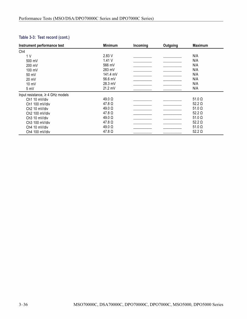
Performance Tests (MSO/DSA/DPO70000C Series and DPO7000C Series)
Table 3-3: Test record (cont.)
Instrument performance test Minimum Incoming Outgoing MaximumCh4
1 V500 mV200 mV100 mV50 mV20 mV10 mV5 mV
2.83 V1.41 V566 mV283 mV141.4 mV56.6 mV28.3 mV21.2 mV
________________________________________________________________________________
________________________________________________________________________________
N/AN/AN/AN/AN/AN/AN/AN/A
Input resistance, ≥ 4 GHz modelsCh1 10 mV/divCh1 100 mV/divCh2 10 mV/divCh2 100 mV/divCh3 10 mV/divCh3 100 mV/divCh4 10 mV/divCh4 100 mV/div
49.0 Ω47.8 Ω49.0 Ω47.8 Ω49.0 Ω47.8 Ω49.0 Ω47.8 Ω
________________________________________________________________________________
________________________________________________________________________________
51.0 Ω52.2 Ω51.0 Ω52.2 Ω51.0 Ω52.2 Ω51.0 Ω52.2 Ω
3–36 MSO70000C, DSA70000C, DPO70000C, DPO7000C, MSO5000, DPO5000 Series
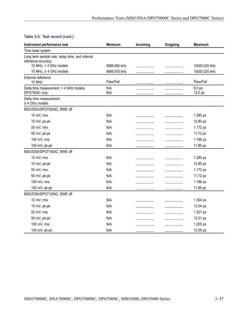
Performance Tests (MSO/DSA/DPO70000C Series and DPO7000C Series)
Table 3-3: Test record (cont.)
Instrument performance test Minimum Incoming Outgoing MaximumTime base systemLong term sample rate, delay time, and internalreference accuracy
10 MHz, < 4 GHz models10 MHz, ≥ 4 GHz models
9999.965 kHz9999.975 kHz
____________________
____________________
10000.035 kHz10000.025 kHz
External reference10 MHz Pass/Fail __________ __________ Pass/Fail
Delta time measurement, < 4 GHz modelsDPO7054C only:
N/AN/A
____________________
____________________
6.0 ps12.0 ps
Delta time measurement≥ 4 GHz modelsMSO/DSA/DPO72004C, BWE off
10 mV, rms N/A __________ __________ 1.280 ps10 mV, pk-pk N/A __________ __________ 12.80 ps50 mV, rms N/A __________ __________ 1.172 ps50 mV, pk-pk N/A __________ __________ 11.72 ps100 mV, rms N/A __________ __________ 1.186 ps100 mV, pk-pk N/A __________ __________ 11.86 ps
MSO/DSA/DPO71604C, BWE off10 mV, rms N/A __________ __________ 1.280 ps10 mV, pk-pk N/A __________ __________ 12.80 ps50 mV, rms N/A __________ __________ 1.172 ps50 mV, pk-pk N/A __________ __________ 11.72 ps100 mV, rms N/A __________ __________ 1.186 ps100 mV, pk-pk N/A __________ __________ 11.86 ps
MSO/DSA/DPO71254C, BWE off10 mV, rms N/A __________ __________ 1.304 ps10 mV, pk-pk N/A __________ __________ 13.04 ps50 mV, rms N/A __________ __________ 1.201 ps50 mV, pk-pk N/A __________ __________ 12.01 ps100 mV, rms N/A __________ __________ 1.205 ps100 mV, pk-pk N/A __________ __________ 12.05 ps
MSO70000C, DSA70000C, DPO70000C, DPO7000C, MSO5000, DPO5000 Series 3–37
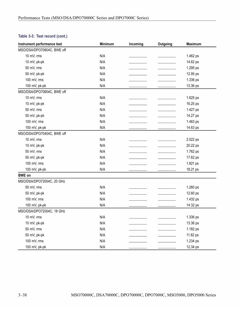
Performance Tests (MSO/DSA/DPO70000C Series and DPO7000C Series)
Table 3-3: Test record (cont.)
Instrument performance test Minimum Incoming Outgoing MaximumMSO/DSA/DPO70804C, BWE off
10 mV, rms N/A __________ __________ 1.462 ps10 mV, pk-pk N/A __________ __________ 14.62 ps50 mV, rms N/A __________ __________ 1.295 ps50 mV, pk-pk N/A __________ __________ 12.95 ps100 mV, rms N/A __________ __________ 1.336 ps100 mV, pk-pk N/A __________ __________ 13.36 ps
MSO/DSA/DPO70604C, BWE off10 mV, rms N/A __________ __________ 1.625 ps10 mV, pk-pk N/A __________ __________ 16.25 ps50 mV, rms N/A __________ __________ 1.427 ps50 mV, pk-pk N/A __________ __________ 14.27 ps100 mV, rms N/A __________ __________ 1.463 ps100 mV, pk-pk N/A __________ __________ 14.63 ps
MSO/DSA/DPO70404C, BWE off10 mV, rms N/A __________ __________ 2.022 ps10 mV, pk-pk N/A __________ __________ 20.22 ps50 mV, rms N/A __________ __________ 1.762 ps50 mV, pk-pk N/A __________ __________ 17.62 ps100 mV, rms N/A __________ __________ 1.821 ps100 mV, pk-pk N/A __________ __________ 18.21 ps
BWE onMSO/DSA/DPO72004C, 20 GHz
50 mV, rms N/A __________ __________ 1.260 ps50 mV, pk-pk N/A __________ __________ 12.60 ps100 mV, rms N/A __________ __________ 1.432 ps100 mV, pk-pk N/A __________ __________ 14.32 ps
MSO/DSA/DPO72004C, 18 GHz10 mV, rms N/A __________ __________ 1.336 ps10 mV, pk-pk N/A __________ __________ 13.36 ps50 mV, rms N/A __________ __________ 1.182 ps50 mV, pk-pk N/A __________ __________ 11.82 ps100 mV, rms N/A __________ __________ 1.234 ps100 mV, pk-pk N/A __________ __________ 12.34 ps
3–38 MSO70000C, DSA70000C, DPO70000C, DPO7000C, MSO5000, DPO5000 Series
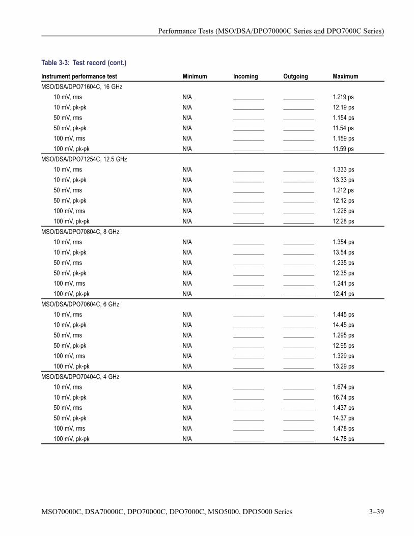
Performance Tests (MSO/DSA/DPO70000C Series and DPO7000C Series)
Table 3-3: Test record (cont.)
Instrument performance test Minimum Incoming Outgoing MaximumMSO/DSA/DPO71604C, 16 GHz
10 mV, rms N/A __________ __________ 1.219 ps10 mV, pk-pk N/A __________ __________ 12.19 ps50 mV, rms N/A __________ __________ 1.154 ps50 mV, pk-pk N/A __________ __________ 11.54 ps100 mV, rms N/A __________ __________ 1.159 ps100 mV, pk-pk N/A __________ __________ 11.59 ps
MSO/DSA/DPO71254C, 12.5 GHz10 mV, rms N/A __________ __________ 1.333 ps10 mV, pk-pk N/A __________ __________ 13.33 ps50 mV, rms N/A __________ __________ 1.212 ps50 mV, pk-pk N/A __________ __________ 12.12 ps100 mV, rms N/A __________ __________ 1.228 ps100 mV, pk-pk N/A __________ __________ 12.28 ps
MSO/DSA/DPO70804C, 8 GHz10 mV, rms N/A __________ __________ 1.354 ps10 mV, pk-pk N/A __________ __________ 13.54 ps50 mV, rms N/A __________ __________ 1.235 ps50 mV, pk-pk N/A __________ __________ 12.35 ps100 mV, rms N/A __________ __________ 1.241 ps100 mV, pk-pk N/A __________ __________ 12.41 ps
MSO/DSA/DPO70604C, 6 GHz10 mV, rms N/A __________ __________ 1.445 ps10 mV, pk-pk N/A __________ __________ 14.45 ps50 mV, rms N/A __________ __________ 1.295 ps50 mV, pk-pk N/A __________ __________ 12.95 ps100 mV, rms N/A __________ __________ 1.329 ps100 mV, pk-pk N/A __________ __________ 13.29 ps
MSO/DSA/DPO70404C, 4 GHz10 mV, rms N/A __________ __________ 1.674 ps10 mV, pk-pk N/A __________ __________ 16.74 ps50 mV, rms N/A __________ __________ 1.437 ps50 mV, pk-pk N/A __________ __________ 14.37 ps100 mV, rms N/A __________ __________ 1.478 ps100 mV, pk-pk N/A __________ __________ 14.78 ps
MSO70000C, DSA70000C, DPO70000C, DPO7000C, MSO5000, DPO5000 Series 3–39
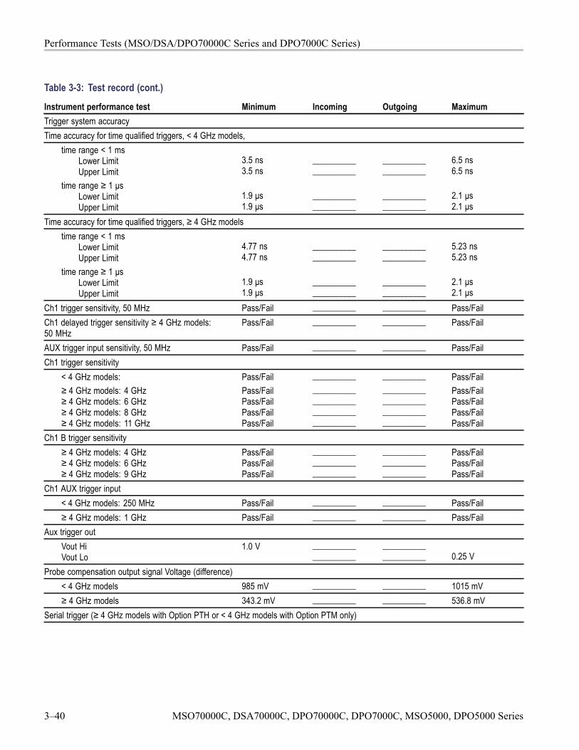
Performance Tests (MSO/DSA/DPO70000C Series and DPO7000C Series)
Table 3-3: Test record (cont.)
Instrument performance test Minimum Incoming Outgoing MaximumTrigger system accuracyTime accuracy for time qualified triggers, < 4 GHz models,
time range < 1 msLower LimitUpper Limit
time range ≥ 1 μsLower LimitUpper Limit
3.5 ns3.5 ns
1.9 μs1.9 μs
____________________
____________________
____________________
____________________
6.5 ns6.5 ns
2.1 μs2.1 μs
Time accuracy for time qualified triggers, ≥ 4 GHz modelstime range < 1 ms
Lower LimitUpper Limit
time range ≥ 1 μsLower LimitUpper Limit
4.77 ns4.77 ns
1.9 μs1.9 μs
____________________
____________________
____________________
____________________
5.23 ns5.23 ns
2.1 μs2.1 μs
Ch1 trigger sensitivity, 50 MHz Pass/Fail __________ __________ Pass/FailCh1 delayed trigger sensitivity ≥ 4 GHz models:50 MHz
Pass/Fail __________ __________ Pass/Fail
AUX trigger input sensitivity, 50 MHz Pass/Fail __________ __________ Pass/FailCh1 trigger sensitivity
< 4 GHz models:≥ 4 GHz models: 4 GHz≥ 4 GHz models: 6 GHz≥ 4 GHz models: 8 GHz≥ 4 GHz models: 11 GHz
Pass/FailPass/FailPass/FailPass/FailPass/Fail
__________________________________________________
__________________________________________________
Pass/FailPass/FailPass/FailPass/FailPass/Fail
Ch1 B trigger sensitivity≥ 4 GHz models: 4 GHz≥ 4 GHz models: 6 GHz≥ 4 GHz models: 9 GHz
Pass/FailPass/FailPass/Fail
______________________________
______________________________
Pass/FailPass/FailPass/Fail
Ch1 AUX trigger input< 4 GHz models: 250 MHz Pass/Fail __________ __________ Pass/Fail≥ 4 GHz models: 1 GHz Pass/Fail __________ __________ Pass/Fail
Aux trigger outVout HiVout Lo
1.0 V ____________________
____________________ 0.25 V
Probe compensation output signal Voltage (difference)< 4 GHz models 985 mV __________ __________ 1015 mV≥ 4 GHz models 343.2 mV __________ __________ 536.8 mV
Serial trigger (≥ 4 GHz models with Option PTH or < 4 GHz models with Option PTM only)
3–40 MSO70000C, DSA70000C, DPO70000C, DPO7000C, MSO5000, DPO5000 Series
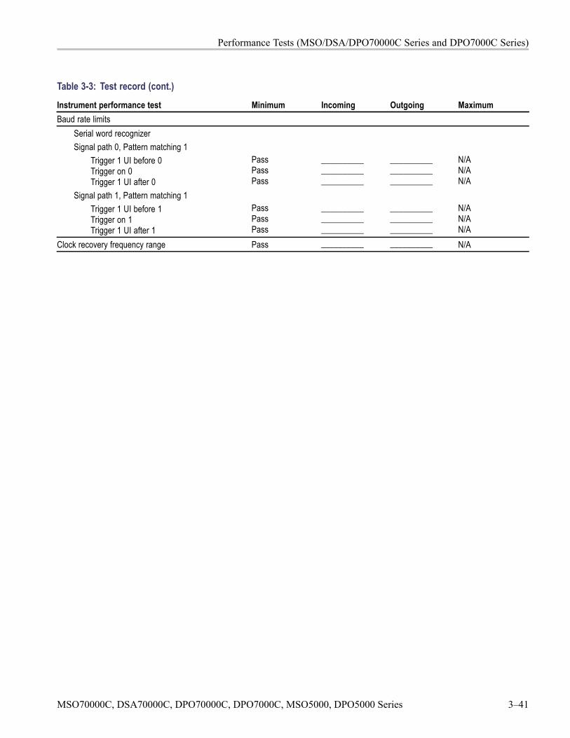
Performance Tests (MSO/DSA/DPO70000C Series and DPO7000C Series)
Table 3-3: Test record (cont.)
Instrument performance test Minimum Incoming Outgoing MaximumBaud rate limits
Serial word recognizerSignal path 0, Pattern matching 1
Trigger 1 UI before 0Trigger on 0Trigger 1 UI after 0
Signal path 1, Pattern matching 1Trigger 1 UI before 1Trigger on 1Trigger 1 UI after 1
PassPassPass
PassPassPass
______________________________
______________________________
______________________________
______________________________
N/AN/AN/A
N/AN/AN/A
Clock recovery frequency range Pass __________ __________ N/A
MSO70000C, DSA70000C, DPO70000C, DPO7000C, MSO5000, DPO5000 Series 3–41
Performance Tests (MSO/DSA/DPO70000C Series and DPO7000C Series)
Signal Acquisition System ChecksThese procedures check those characteristics that relate to the signal-acquisitionsystem and are listed as checked under Warranted Characteristics inSpecifications. (See Table 3-2.) for test equipment specifications.
Check DC VoltageMeasurement Accuracy
Equipment Required PrerequisitesOne DC calibration generator (Item 6)One SMA male-to-BNC female adapter (Item19)
The instrument must meet the prerequisites.(See page 3-18, Prerequisites.)
WARNING. The generator is capable of outputting dangerous voltages. Be sure toset the DC calibration generator to off or 0 volts before connecting, disconnecting,and/or moving the test hookup during the performance of this procedure.
1. Install the test hookup and preset the instrument controls:
a. Hook up the test-signal source:
Set the output of a DC calibration generator to off or 0 volts. Set theDC impedance of the generator to 50 Ω.
Connect the output of a DC calibration generator. (See Figure 3-20.)
b. Initialize the instrument: Press DEFAULT SETUP.
c. Modify the default settings:
From the button bar, touch Horiz/Acq and select the Acquisition tab.
Touch Average and set the number of averages to 16.
< 4 GHz models: Touch Vertical, select Vertical Setup, and thentouch Termination 50 Ω.
3–42 MSO70000C, DSA70000C, DPO70000C, DPO7000C, MSO5000, DPO5000 Series
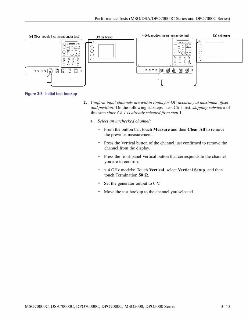
Performance Tests (MSO/DSA/DPO70000C Series and DPO7000C Series)
Figure 3-8: Initial test hookup
2. Confirm input channels are within limits for DC accuracy at maximum offsetand position: Do the following substeps - test Ch 1 first, skipping substep a ofthis step since Ch 1 is already selected from step 1.
a. Select an unchecked channel:
From the button bar, touchMeasure and then Clear All to removethe previous measurement.
Press the Vertical button of the channel just confirmed to remove thechannel from the display.
Press the front-panel Vertical button that corresponds to the channelyou are to confirm.
< 4 GHz models: Touch Vertical, select Vertical Setup, and thentouch Termination 50 Ω.
Set the generator output to 0 V.
Move the test hookup to the channel you selected.
MSO70000C, DSA70000C, DPO70000C, DPO7000C, MSO5000, DPO5000 Series 3–43
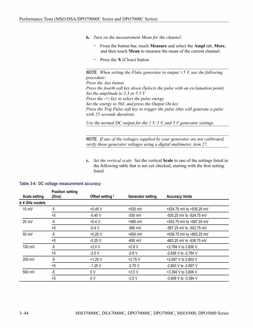
Performance Tests (MSO/DSA/DPO70000C Series and DPO7000C Series)
b. Turn on the measurement Mean for the channel:
From the button bar, touchMeasure and select the Ampl tab,More,and then touchMean to measure the mean of the current channel.
Press the X (Close) button.
NOTE. When setting the Fluke generator to output >5 V, use the followingprocedure:Press the Aux buttonPress the fourth soft key down (Selects the pulse with an exclamation point)Set the amplitude to 5.3 or 5.5 VPress the ->| key to select the pulse energySet the energy to 50J, and press the Output On keyPress the Trig Pulse soft key to trigger the pulse (this will generate a pulsewith 25 seconds duration).
Use the normal DC output for the 1 V, 3 V, and 5 V generator settings.
NOTE. If any of the voltages supplied by your generator are not calibrated,verify those generator voltages using a digital multimeter, item 27.
c. Set the vertical scale: Set the vertical Scale to one of the settings listed inthe following table that is not yet checked, starting with the first settinglisted.
Table 3-4: DC voltage measurement accuracy
Scale settingPosition setting(Divs) Offset setting 1 Generator setting Accuracy limits
≥ 4 GHz models10 mV -5 +0.45 V +530 mV +524.75 mV to +535.25 mV
+5 -0.45 V -530 mV -535.25 mV to -524.75 mV20 mV -5 +0.4 V +560 mV +552.75 mV to +567.25 mV
+5 -0.4 V -560 mV -567.25 mV to -552.75 mV-5 +0.25 V +650 mV +636.75 mV to +663.25 mV50 mV+5 -0.25 V -650 mV -663.25 mV to -636.75 mV-5 +2.0 V +2.8 V +2.764 V to 2.836 V100 mV+5 -2.0 V -2.8 V -2.836 V to -2.764 V-5 +1.25 V +2.75 V +2.697 V to 2.803 V200 mV+5 -1.25 V -2.75 V -2.803 V to -2.697 V-5 0 V +3.5 V +3.394 V to 3.606 V500 mV+5 0 V -3.5 V -3.606 V to -3.394 V
3–44 MSO70000C, DSA70000C, DPO70000C, DPO7000C, MSO5000, DPO5000 Series
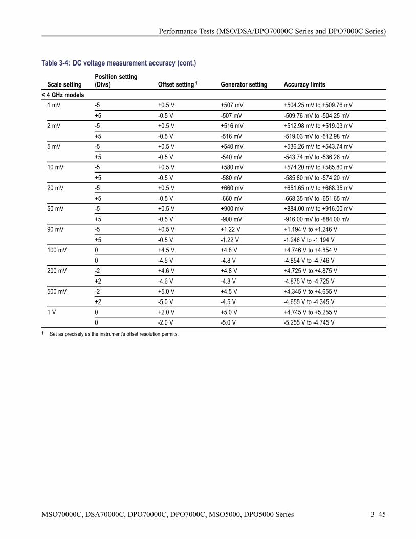
Performance Tests (MSO/DSA/DPO70000C Series and DPO7000C Series)
Table 3-4: DC voltage measurement accuracy (cont.)
Scale settingPosition setting(Divs) Offset setting 1 Generator setting Accuracy limits
< 4 GHz models-5 +0.5 V +507 mV +504.25 mV to +509.76 mV1 mV+5 -0.5 V -507 mV -509.76 mV to -504.25 mV-5 +0.5 V +516 mV +512.98 mV to +519.03 mV2 mV+5 -0.5 V -516 mV -519.03 mV to -512.98 mV-5 +0.5 V +540 mV +536.26 mV to +543.74 mV5 mV+5 -0.5 V -540 mV -543.74 mV to -536.26 mV-5 +0.5 V +580 mV +574.20 mV to +585.80 mV10 mV+5 -0.5 V -580 mV -585.80 mV to -574.20 mV-5 +0.5 V +660 mV +651.65 mV to +668.35 mV20 mV+5 -0.5 V -660 mV -668.35 mV to -651.65 mV-5 +0.5 V +900 mV +884.00 mV to +916.00 mV50 mV+5 -0.5 V -900 mV -916.00 mV to -884.00 mV-5 +0.5 V +1.22 V +1.194 V to +1.246 V90 mV+5 -0.5 V -1.22 V -1.246 V to -1.194 V0 +4.5 V +4.8 V +4.746 V to +4.854 V100 mV0 -4.5 V -4.8 V -4.854 V to -4.746 V-2 +4.6 V +4.8 V +4.725 V to +4.875 V200 mV+2 -4.6 V -4.8 V -4.875 V to -4.725 V-2 +5.0 V +4.5 V +4.345 V to +4.655 V500 mV+2 -5.0 V -4.5 V -4.655 V to -4.345 V0 +2.0 V +5.0 V +4.745 V to +5.255 V1 V0 -2.0 V -5.0 V -5.255 V to -4.745 V
1 Set as precisely as the instrument's offset resolution permits.
MSO70000C, DSA70000C, DPO70000C, DPO7000C, MSO5000, DPO5000 Series 3–45
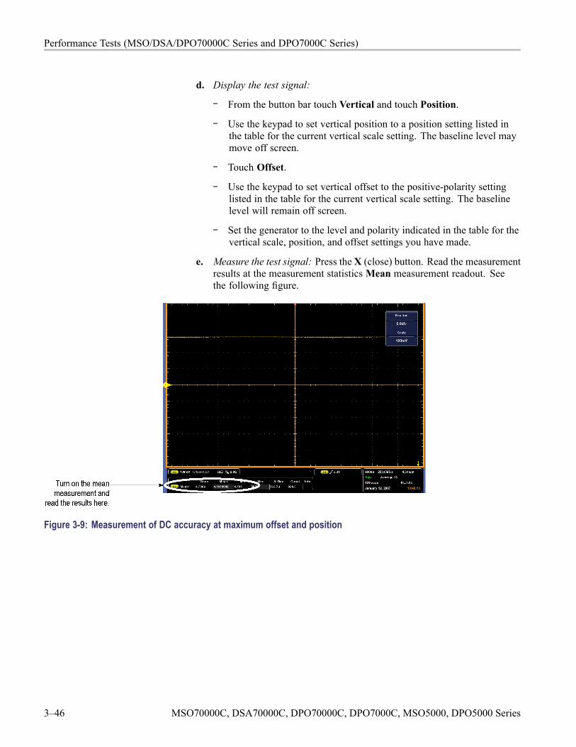
Performance Tests (MSO/DSA/DPO70000C Series and DPO7000C Series)
d. Display the test signal:
From the button bar touch Vertical and touch Position.
Use the keypad to set vertical position to a position setting listed inthe table for the current vertical scale setting. The baseline level maymove off screen.
Touch Offset.
Use the keypad to set vertical offset to the positive-polarity settinglisted in the table for the current vertical scale setting. The baselinelevel will remain off screen.
Set the generator to the level and polarity indicated in the table for thevertical scale, position, and offset settings you have made.
e. Measure the test signal: Press the X (close) button. Read the measurementresults at the measurement statisticsMean measurement readout. Seethe following figure.
Figure 3-9: Measurement of DC accuracy at maximum offset and position
3–46 MSO70000C, DSA70000C, DPO70000C, DPO7000C, MSO5000, DPO5000 Series
Performance Tests (MSO/DSA/DPO70000C Series and DPO7000C Series)
f. Check against limits:
CHECK that the readout for the measurement Mean readout onscreen is within the limits listed for the current vertical scale andposition/offset/generator settings. Enter the value on test record.
Repeat substep d, reversing the polarity of the position, offset, andgenerator settings as is listed in the table.
CHECK that the Mean measurement readout on screen iswithin the limits listed for the current vertical scale setting andposition/offset/generator settings. Enter the value on test record.
Repeat substeps c through f until all vertical scale settings are checkedfor the channel under test. (See Table 3-5.)
g. Test all channels: Repeat step 2 substeps a through f for all four channels.
3. Disconnect the hookup:
a. Set the generator output to 0 V.
b. Disconnect the equipment from the generator output and the inputconnector of the channel last tested.
MSO70000C, DSA70000C, DPO70000C, DPO7000C, MSO5000, DPO5000 Series 3–47
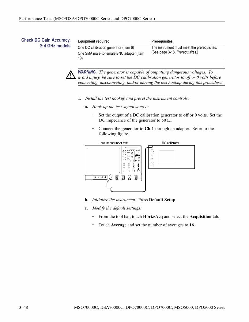
Performance Tests (MSO/DSA/DPO70000C Series and DPO7000C Series)
Check DC Gain Accuracy,≥ 4 GHz models
Equipment required PrerequisitesOne DC calibration generator (Item 6)One SMA male-to-female BNC adapter (Item19)
The instrument must meet the prerequisites.(See page 3-18, Prerequisites.)
WARNING. The generator is capable of outputting dangerous voltages. Toavoid injury, be sure to set the DC calibration generator to off or 0 volts beforeconnecting, disconnecting, and/or moving the test hookup during this procedure.
1. Install the test hookup and preset the instrument controls:
a. Hook up the test-signal source:
Set the output of a DC calibration generator to off or 0 volts. Set theDC impedance of the generator to 50 Ω.
Connect the generator to Ch 1 through an adapter. Refer to thefollowing figure.
b. Initialize the instrument: Press Default Setup
c. Modify the default settings:
From the tool bar, touch Horiz/Acq and select the Acquisition tab.
Touch Average and set the number of averages to 16.
3–48 MSO70000C, DSA70000C, DPO70000C, DPO7000C, MSO5000, DPO5000 Series
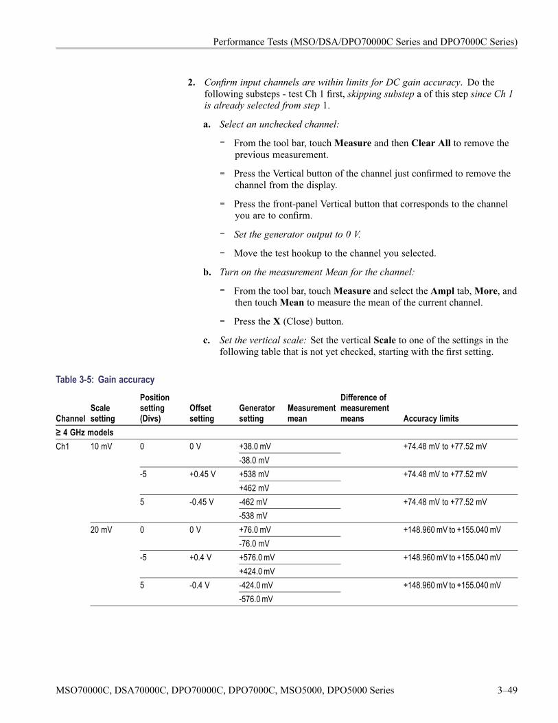
Performance Tests (MSO/DSA/DPO70000C Series and DPO7000C Series)
2. Confirm input channels are within limits for DC gain accuracy. Do thefollowing substeps - test Ch 1 first, skipping substep a of this step since Ch 1is already selected from step 1.
a. Select an unchecked channel:
From the tool bar, touchMeasure and then Clear All to remove theprevious measurement.
Press the Vertical button of the channel just confirmed to remove thechannel from the display.
Press the front-panel Vertical button that corresponds to the channelyou are to confirm.
Set the generator output to 0 V.
Move the test hookup to the channel you selected.
b. Turn on the measurement Mean for the channel:
From the tool bar, touchMeasure and select the Ampl tab,More, andthen touchMean to measure the mean of the current channel.
Press the X (Close) button.
c. Set the vertical scale: Set the vertical Scale to one of the settings in thefollowing table that is not yet checked, starting with the first setting.
Table 3-5: Gain accuracy
ChannelScalesetting
Positionsetting(Divs)
Offsetsetting
Generatorsetting
Measurementmean
Difference ofmeasurementmeans Accuracy limits
≥ 4 GHz modelsCh1 +38.0 mV0 0 V
-38.0 mV+74.48 mV to +77.52 mV
+538 mV-5 +0.45 V+462 mV
+74.48 mV to +77.52 mV
-462 mV
10 mV
5 -0.45 V-538 mV
+74.48 mV to +77.52 mV
+76.0 mV0 0 V-76.0 mV
+148.960 mV to +155.040 mV
+576.0 mV-5 +0.4 V+424.0 mV
+148.960 mV to +155.040 mV
-424.0 mV
20 mV
5 -0.4 V-576.0 mV
+148.960 mV to +155.040 mV
MSO70000C, DSA70000C, DPO70000C, DPO7000C, MSO5000, DPO5000 Series 3–49
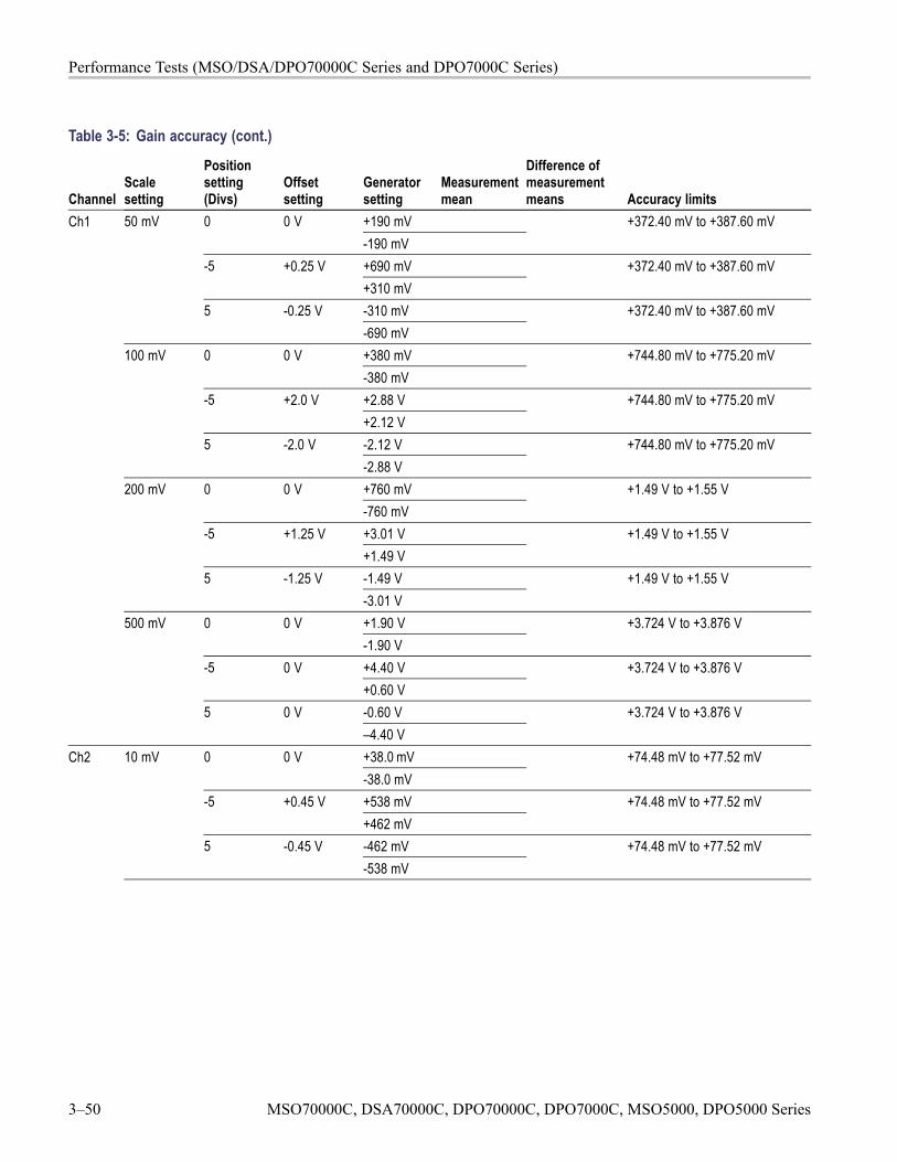
Performance Tests (MSO/DSA/DPO70000C Series and DPO7000C Series)
Table 3-5: Gain accuracy (cont.)
ChannelScalesetting
Positionsetting(Divs)
Offsetsetting
Generatorsetting
Measurementmean
Difference ofmeasurementmeans Accuracy limits
Ch1 +190 mV0 0 V-190 mV
+372.40 mV to +387.60 mV
+690 mV-5 +0.25 V+310 mV
+372.40 mV to +387.60 mV
-310 mV
50 mV
5 -0.25 V-690 mV
+372.40 mV to +387.60 mV
+380 mV0 0 V-380 mV
+744.80 mV to +775.20 mV
+2.88 V-5 +2.0 V+2.12 V
+744.80 mV to +775.20 mV
-2.12 V
100 mV
5 -2.0 V-2.88 V
+744.80 mV to +775.20 mV
+760 mV0 0 V-760 mV
+1.49 V to +1.55 V
+3.01 V-5 +1.25 V+1.49 V
+1.49 V to +1.55 V
-1.49 V
200 mV
5 -1.25 V-3.01 V
+1.49 V to +1.55 V
+1.90 V0 0 V-1.90 V
+3.724 V to +3.876 V
+4.40 V-5 0 V+0.60 V
+3.724 V to +3.876 V
-0.60 V
500 mV
5 0 V–4.40 V
+3.724 V to +3.876 V
Ch2 +38.0 mV0 0 V-38.0 mV
+74.48 mV to +77.52 mV
+538 mV-5 +0.45 V+462 mV
+74.48 mV to +77.52 mV
-462 mV
10 mV
5 -0.45 V-538 mV
+74.48 mV to +77.52 mV
3–50 MSO70000C, DSA70000C, DPO70000C, DPO7000C, MSO5000, DPO5000 Series
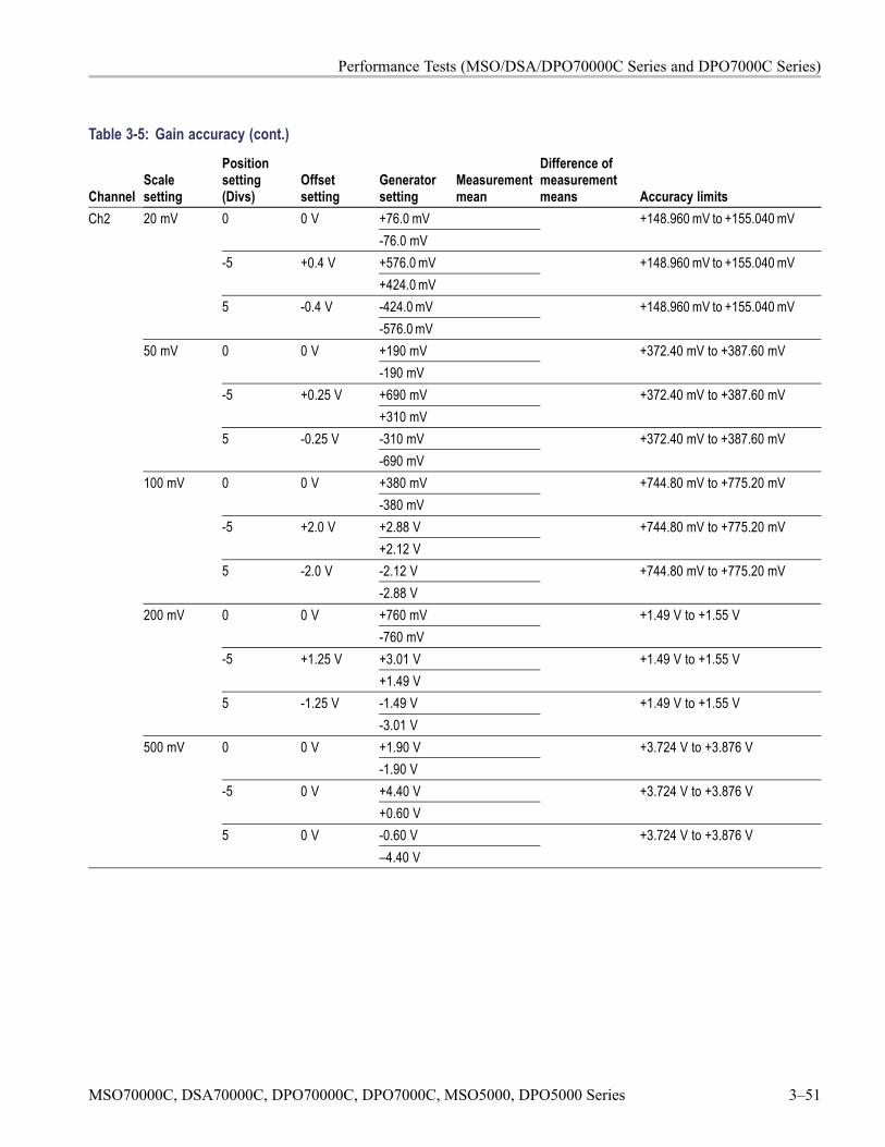
Performance Tests (MSO/DSA/DPO70000C Series and DPO7000C Series)
Table 3-5: Gain accuracy (cont.)
ChannelScalesetting
Positionsetting(Divs)
Offsetsetting
Generatorsetting
Measurementmean
Difference ofmeasurementmeans Accuracy limits
Ch2 +76.0 mV0 0 V-76.0 mV
+148.960 mV to +155.040 mV
+576.0 mV-5 +0.4 V+424.0 mV
+148.960 mV to +155.040 mV
-424.0 mV
20 mV
5 -0.4 V-576.0 mV
+148.960 mV to +155.040 mV
+190 mV0 0 V-190 mV
+372.40 mV to +387.60 mV
+690 mV-5 +0.25 V+310 mV
+372.40 mV to +387.60 mV
-310 mV
50 mV
5 -0.25 V-690 mV
+372.40 mV to +387.60 mV
+380 mV0 0 V-380 mV
+744.80 mV to +775.20 mV
+2.88 V-5 +2.0 V+2.12 V
+744.80 mV to +775.20 mV
-2.12 V
100 mV
5 -2.0 V-2.88 V
+744.80 mV to +775.20 mV
+760 mV0 0 V-760 mV
+1.49 V to +1.55 V
+3.01 V-5 +1.25 V+1.49 V
+1.49 V to +1.55 V
-1.49 V
200 mV
5 -1.25 V-3.01 V
+1.49 V to +1.55 V
+1.90 V0 0 V-1.90 V
+3.724 V to +3.876 V
+4.40 V-5 0 V+0.60 V
+3.724 V to +3.876 V
-0.60 V
500 mV
5 0 V–4.40 V
+3.724 V to +3.876 V
MSO70000C, DSA70000C, DPO70000C, DPO7000C, MSO5000, DPO5000 Series 3–51

Performance Tests (MSO/DSA/DPO70000C Series and DPO7000C Series)
Table 3-5: Gain accuracy (cont.)
ChannelScalesetting
Positionsetting(Divs)
Offsetsetting
Generatorsetting
Measurementmean
Difference ofmeasurementmeans Accuracy limits
Ch3 +38.0 mV0 0 V-38.0 mV
+74.48 mV to +77.52 mV
+538 mV-5 +0.45 V+462 mV
+74.48 mV to +77.52 mV
-462 mV
10 mV
5 -0.45 V-538 mV
+74.48 mV to +77.52 mV
+76.0 mV0 0 V-76.0 mV
+148.960 mV to +155.040 mV
+576.0 mV-5 +0.4 V+424.0 mV
+148.960 mV to +155.040 mV
-424.0 mV
20 mV
5 -0.4 V-576.0 mV
+148.960 mV to +155.040 mV
+190 mV0 0 V-190 mV
+372.40 mV to +387.60 mV
+690 mV-5 +0.25 V+310 mV
+372.40 mV to +387.60 mV
-310 mV
50 mV
5 -0.25 V-690 mV
+372.40 mV to +387.60 mV
+380 mV0 0 V-380 mV
+744.80 mV to +775.20 mV
+2.88 V-5 +2.0 V+2.12 V
+744.80 mV to +775.20 mV
-2.12 V
100 mV
5 -2.0 V-2.88 V
+744.80 mV to +775.20 mV
+760 mV0 0 V-760 mV
+1.49 V to +1.55 V
+3.01 V-5 +1.25 V+1.49 V
+1.49 V to +1.55 V
-1.49 V
200 mV
5 -1.25 V-3.01 V
+1.49 V to +1.55 V
3–52 MSO70000C, DSA70000C, DPO70000C, DPO7000C, MSO5000, DPO5000 Series
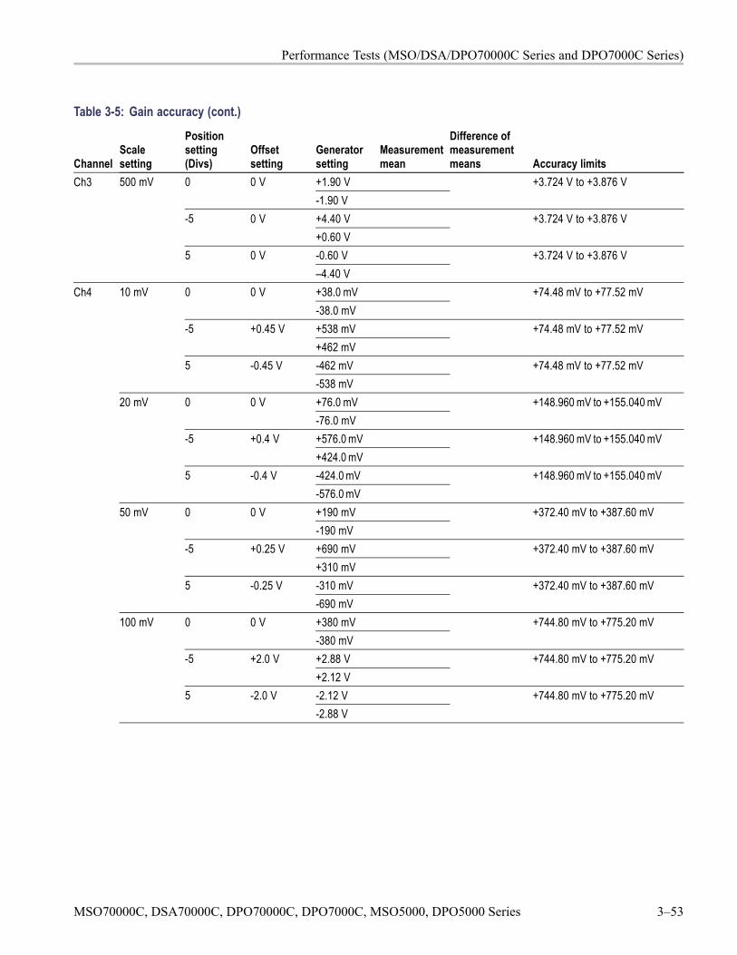
Performance Tests (MSO/DSA/DPO70000C Series and DPO7000C Series)
Table 3-5: Gain accuracy (cont.)
ChannelScalesetting
Positionsetting(Divs)
Offsetsetting
Generatorsetting
Measurementmean
Difference ofmeasurementmeans Accuracy limits
Ch3 +1.90 V0 0 V-1.90 V
+3.724 V to +3.876 V
+4.40 V-5 0 V+0.60 V
+3.724 V to +3.876 V
-0.60 V
500 mV
5 0 V–4.40 V
+3.724 V to +3.876 V
Ch4 +38.0 mV0 0 V-38.0 mV
+74.48 mV to +77.52 mV
+538 mV-5 +0.45 V+462 mV
+74.48 mV to +77.52 mV
-462 mV
10 mV
5 -0.45 V-538 mV
+74.48 mV to +77.52 mV
+76.0 mV0 0 V-76.0 mV
+148.960 mV to +155.040 mV
+576.0 mV-5 +0.4 V+424.0 mV
+148.960 mV to +155.040 mV
-424.0 mV
20 mV
5 -0.4 V-576.0 mV
+148.960 mV to +155.040 mV
+190 mV0 0 V-190 mV
+372.40 mV to +387.60 mV
+690 mV-5 +0.25 V+310 mV
+372.40 mV to +387.60 mV
-310 mV
50 mV
5 -0.25 V-690 mV
+372.40 mV to +387.60 mV
+380 mV0 0 V-380 mV
+744.80 mV to +775.20 mV
+2.88 V-5 +2.0 V+2.12 V
+744.80 mV to +775.20 mV
-2.12 V
100 mV
5 -2.0 V-2.88 V
+744.80 mV to +775.20 mV
MSO70000C, DSA70000C, DPO70000C, DPO7000C, MSO5000, DPO5000 Series 3–53
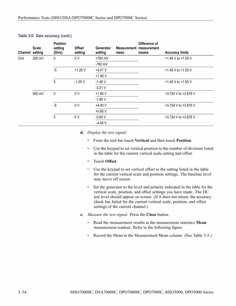
Performance Tests (MSO/DSA/DPO70000C Series and DPO7000C Series)
Table 3-5: Gain accuracy (cont.)
ChannelScalesetting
Positionsetting(Divs)
Offsetsetting
Generatorsetting
Measurementmean
Difference ofmeasurementmeans Accuracy limits
Ch4 +760 mV0 0 V-760 mV
+1.49 V to +1.55 V
+3.01 V-5 +1.25 V+1.49 V
+1.49 V to +1.55 V
-1.49 V
200 mV
5 -1.25 V-3.01 V
+1.49 V to +1.55 V
+1.90 V0 0 V-1.90 V
+3.724 V to +3.876 V
+4.40 V-5 0 V+0.60 V
+3.724 V to +3.876 V
-0.60 V
500 mV
5 0 V–4.40 V
+3.724 V to +3.876 V
d. Display the test signal:
From the tool bar touch Vertical and then touch Position.
Use the keypad to set vertical position to the number of divisions listedin the table for the current vertical scale setting and offset.
Touch Offset.
Use the keypad to set vertical offset to the setting listed in the tablefor the current vertical scale and position settings. The baseline levelmay move off screen.
Set the generator to the level and polarity indicated in the table for thevertical scale, position, and offset settings you have made. The DCtest level should appear on screen. (If it does not return, the accuracycheck has failed for the current vertical scale, position, and offsetsettings of the current channel.)
e. Measure the test signal: Press the Close button.
Read the measurement results at the measurement statisticsMeanmeasurement readout. Refer to the following figure.
Record the Mean in the Measurement Mean column. (See Table 3-5.)
3–54 MSO70000C, DSA70000C, DPO70000C, DPO7000C, MSO5000, DPO5000 Series
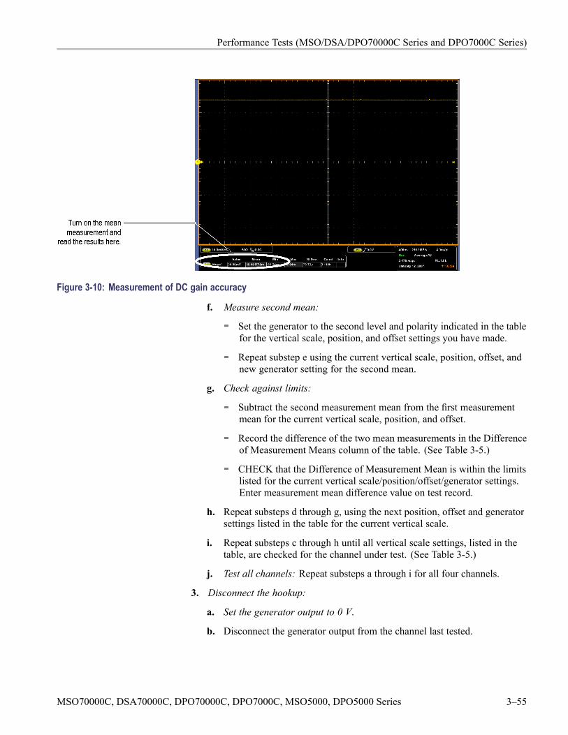
Performance Tests (MSO/DSA/DPO70000C Series and DPO7000C Series)
Figure 3-10: Measurement of DC gain accuracy
f. Measure second mean:
Set the generator to the second level and polarity indicated in the tablefor the vertical scale, position, and offset settings you have made.
Repeat substep e using the current vertical scale, position, offset, andnew generator setting for the second mean.
g. Check against limits:
Subtract the second measurement mean from the first measurementmean for the current vertical scale, position, and offset.
Record the difference of the two mean measurements in the Differenceof Measurement Means column of the table. (See Table 3-5.)
CHECK that the Difference of Measurement Mean is within the limitslisted for the current vertical scale/position/offset/generator settings.Enter measurement mean difference value on test record.
h. Repeat substeps d through g, using the next position, offset and generatorsettings listed in the table for the current vertical scale.
i. Repeat substeps c through h until all vertical scale settings, listed in thetable, are checked for the channel under test. (See Table 3-5.)
j. Test all channels: Repeat substeps a through i for all four channels.
3. Disconnect the hookup:
a. Set the generator output to 0 V.
b. Disconnect the generator output from the channel last tested.
MSO70000C, DSA70000C, DPO70000C, DPO7000C, MSO5000, DPO5000 Series 3–55
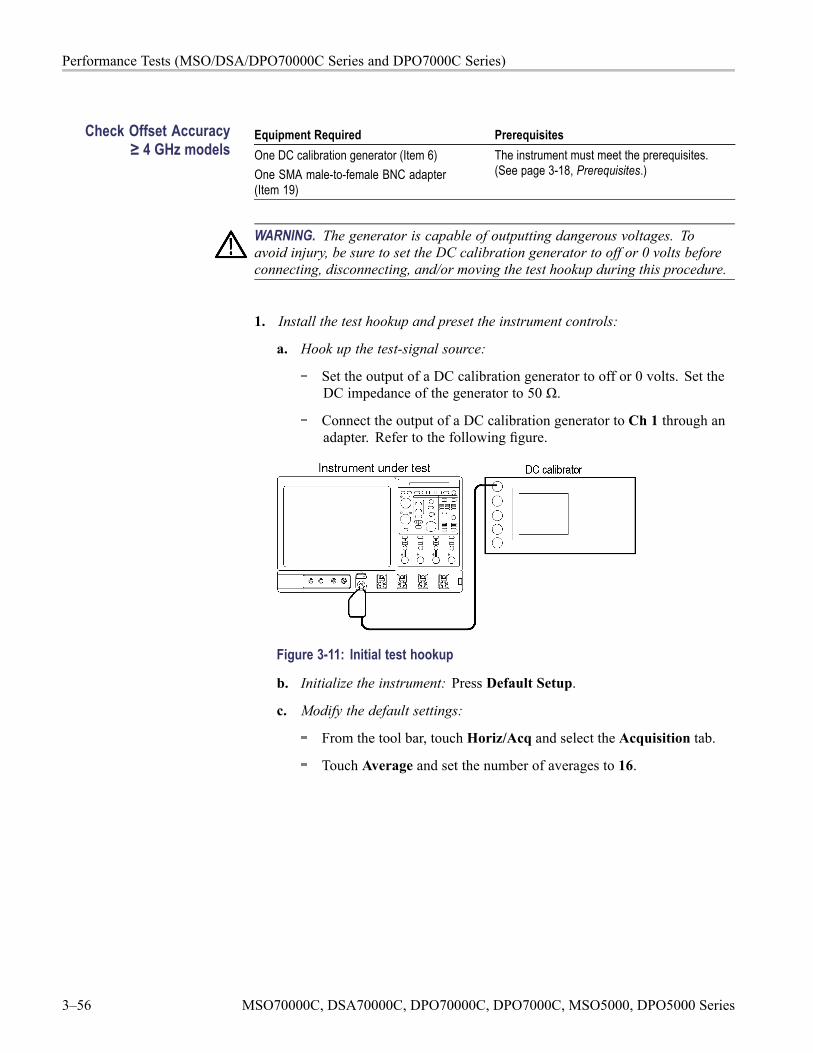
Performance Tests (MSO/DSA/DPO70000C Series and DPO7000C Series)
Check Offset Accuracy≥ 4 GHz models
Equipment Required PrerequisitesOne DC calibration generator (Item 6)One SMA male-to-female BNC adapter(Item 19)
The instrument must meet the prerequisites.(See page 3-18, Prerequisites.)
WARNING. The generator is capable of outputting dangerous voltages. Toavoid injury, be sure to set the DC calibration generator to off or 0 volts beforeconnecting, disconnecting, and/or moving the test hookup during this procedure.
1. Install the test hookup and preset the instrument controls:
a. Hook up the test-signal source:
Set the output of a DC calibration generator to off or 0 volts. Set theDC impedance of the generator to 50 Ω.
Connect the output of a DC calibration generator to Ch 1 through anadapter. Refer to the following figure.
Figure 3-11: Initial test hookup
b. Initialize the instrument: Press Default Setup.
c. Modify the default settings:
From the tool bar, touch Horiz/Acq and select the Acquisition tab.
Touch Average and set the number of averages to 16.
3–56 MSO70000C, DSA70000C, DPO70000C, DPO7000C, MSO5000, DPO5000 Series
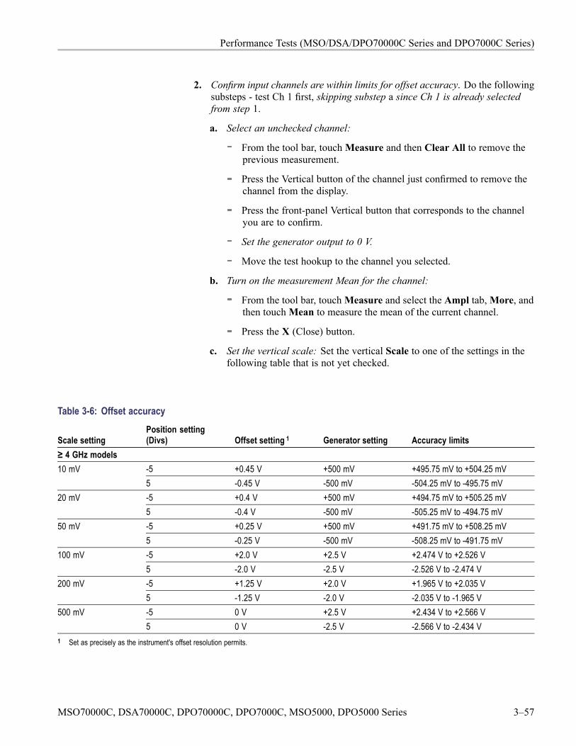
Performance Tests (MSO/DSA/DPO70000C Series and DPO7000C Series)
2. Confirm input channels are within limits for offset accuracy. Do the followingsubsteps - test Ch 1 first, skipping substep a since Ch 1 is already selectedfrom step 1.
a. Select an unchecked channel:
From the tool bar, touchMeasure and then Clear All to remove theprevious measurement.
Press the Vertical button of the channel just confirmed to remove thechannel from the display.
Press the front-panel Vertical button that corresponds to the channelyou are to confirm.
Set the generator output to 0 V.
Move the test hookup to the channel you selected.
b. Turn on the measurement Mean for the channel:
From the tool bar, touchMeasure and select the Ampl tab,More, andthen touchMean to measure the mean of the current channel.
Press the X (Close) button.
c. Set the vertical scale: Set the vertical Scale to one of the settings in thefollowing table that is not yet checked.
Table 3-6: Offset accuracy
Scale settingPosition setting(Divs) Offset setting 1 Generator setting Accuracy limits
≥ 4 GHz models-5 +0.45 V +500 mV +495.75 mV to +504.25 mV10 mV5 -0.45 V -500 mV -504.25 mV to -495.75 mV-5 +0.4 V +500 mV +494.75 mV to +505.25 mV20 mV5 -0.4 V -500 mV -505.25 mV to -494.75 mV-5 +0.25 V +500 mV +491.75 mV to +508.25 mV50 mV5 -0.25 V -500 mV -508.25 mV to -491.75 mV-5 +2.0 V +2.5 V +2.474 V to +2.526 V100 mV5 -2.0 V -2.5 V -2.526 V to -2.474 V-5 +1.25 V +2.0 V +1.965 V to +2.035 V200 mV5 -1.25 V -2.0 V -2.035 V to -1.965 V-5 0 V +2.5 V +2.434 V to +2.566 V500 mV5 0 V -2.5 V -2.566 V to -2.434 V
1 Set as precisely as the instrument's offset resolution permits.
MSO70000C, DSA70000C, DPO70000C, DPO7000C, MSO5000, DPO5000 Series 3–57
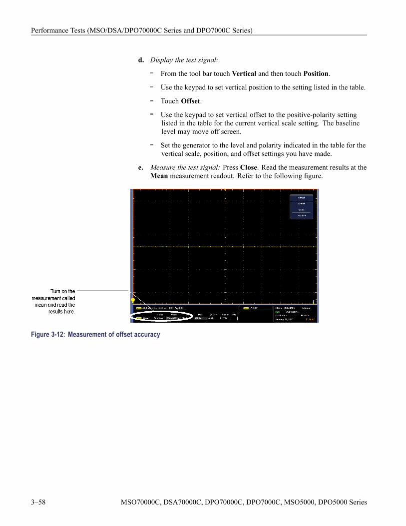
Performance Tests (MSO/DSA/DPO70000C Series and DPO7000C Series)
d. Display the test signal:
From the tool bar touch Vertical and then touch Position.
Use the keypad to set vertical position to the setting listed in the table.
Touch Offset.
Use the keypad to set vertical offset to the positive-polarity settinglisted in the table for the current vertical scale setting. The baselinelevel may move off screen.
Set the generator to the level and polarity indicated in the table for thevertical scale, position, and offset settings you have made.
e. Measure the test signal: Press Close. Read the measurement results at theMean measurement readout. Refer to the following figure.
Figure 3-12: Measurement of offset accuracy
3–58 MSO70000C, DSA70000C, DPO70000C, DPO7000C, MSO5000, DPO5000 Series
Performance Tests (MSO/DSA/DPO70000C Series and DPO7000C Series)
f. Check against limits:
CHECK that the readout for the measurement Mean readout onscreen is within the limits listed for the current vertical scale andposition/offset/generator settings. Enter the value on the test record.
Repeat substep d, using the offset and generator settings as is listedin the table.
CHECK that the Mean measurement readout on screen iswithin the limits listed for the current vertical scale setting andposition/offset/generator settings. Enter the value on the test record.
Repeat substep d, using the negative-polarity offset and generatorsettings as is listed in the table.
CHECK that the Mean measurement readout on screen iswithin the limits listed for the current vertical scale setting andposition/offset/generator settings. Enter the value on the test record.
Repeat substeps c through f until all vertical scale settings, are checkedfor the channel under test. (See Table 3-6.)
g. Test all channels: Repeat substeps a through f for all four channels.
3. Disconnect the hookup:
a. Set the generator output to 0 V.
b. Disconnect the generator from the channel last tested.
MSO70000C, DSA70000C, DPO70000C, DPO7000C, MSO5000, DPO5000 Series 3–59
Performance Tests (MSO/DSA/DPO70000C Series and DPO7000C Series)
Check Analog Bandwidth,< 3.5 GHz models
Equipment required PrerequisitesOne sine wave generator (Item 9)One level meter and power sensor (Item 10)One power splitter (Item 11)50 Ω precision cable 2.92 mm male-to-female(Item 12)One K male-to-male adapter (Item 13)SMA male-to-BNC female adapter (Item 19)
(See page 3-18, Prerequisites.)
1. Install the test hookup and preset the instrument controls:
a. Initialize the instrument:
Press Default Setup.
b. Modify the default settings:
Touch Vertical, select Vertical Setup, and then touch Termination50 Ω.
From the Bandwidth drop-down list, select the maximum bandwidthfor your instrument.
Turn the horizontal Scale knob to 50 ns.
From the button bar, touch Horiz/Acq and select the Horizontal tab.Select Constant Sample Rate mode. Set the Sample Rate to 200 GS/s.
From the button bar, touch Horiz/Acq and select the Acquisition tab.Set the acquisition mode as follows:
Touch Average and set the number of averages to 16.
Set the sampling mode as follows:
Touch the Equivalent ET button.
From the button bar, touchMeasure. Touch Setups Ref Levs; thentouch the Histogram button.
c. Hook up the test-signal source: Connect the sine wave output of a sinewave generator to Ch 1 through a power splitter. Connect the powersensor of the power meter to the power splitter. (See Figure 3-13.) Set theoutput of the generator to a reference frequency of 50 MHz or less.
3–60 MSO70000C, DSA70000C, DPO70000C, DPO7000C, MSO5000, DPO5000 Series
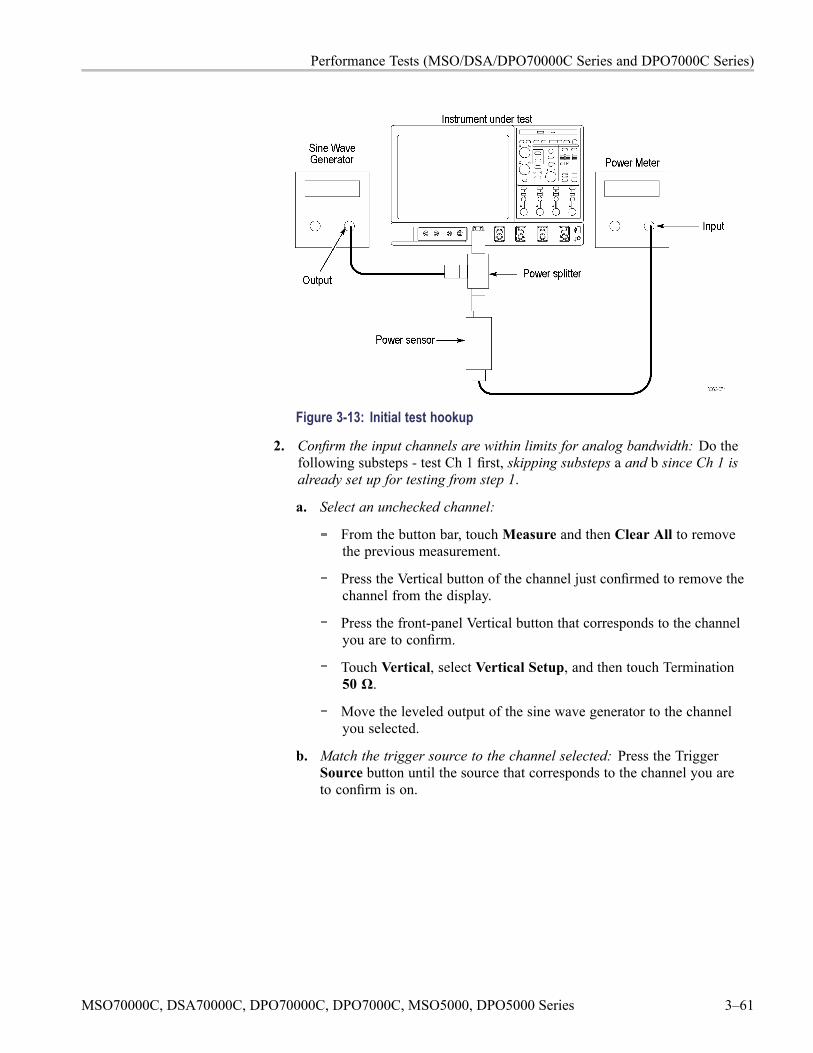
Performance Tests (MSO/DSA/DPO70000C Series and DPO7000C Series)
Figure 3-13: Initial test hookup
2. Confirm the input channels are within limits for analog bandwidth: Do thefollowing substeps - test Ch 1 first, skipping substeps a and b since Ch 1 isalready set up for testing from step 1.
a. Select an unchecked channel:
From the button bar, touchMeasure and then Clear All to removethe previous measurement.
Press the Vertical button of the channel just confirmed to remove thechannel from the display.
Press the front-panel Vertical button that corresponds to the channelyou are to confirm.
Touch Vertical, select Vertical Setup, and then touch Termination50 Ω.
Move the leveled output of the sine wave generator to the channelyou selected.
b. Match the trigger source to the channel selected: Press the TriggerSource button until the source that corresponds to the channel you areto confirm is on.
MSO70000C, DSA70000C, DPO70000C, DPO7000C, MSO5000, DPO5000 Series 3–61
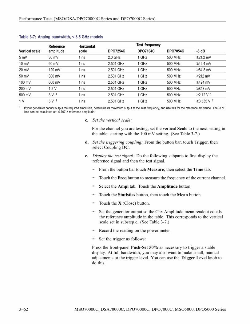
Performance Tests (MSO/DSA/DPO70000C Series and DPO7000C Series)
Table 3-7: Analog bandwidth, < 3.5 GHz modelsTest frequency
Vertical scaleReferenceamplitude
Horizontalscale DPO7254C DPO7104C DPO7054C -3 dB
5 mV 30 mV 1 ns 2.0 GHz 1 GHz 500 MHz ≥21.2 mV10 mV 60 mV 1 ns 2.501 GHz 1 GHz 500 MHz ≥42.4 mV20 mV 120 mV 1 ns 2.501 GHz 1 GHz 500 MHz ≥84.8 mV50 mV 300 mV 1 ns 2.501 GHz 1 GHz 500 MHz ≥212 mV100 mV 600 mV 1 ns 2.501 GHz 1 GHz 500 MHz ≥424 mV200 mV 1.2 V 1 ns 2.501 GHz 1 GHz 500 MHz ≥848 mV500 mV 3 V 1 1 ns 2.501 GHz 1 GHz 500 MHz ≥2.12 V 1
1 V 5 V 1 1 ns 2.501 GHz 1 GHz 500 MHz ≥3.535 V 1
1 If your generator cannot output the required amplitude, determine its maximum output at the Test frequency, and use this for the reference amplitude. The -3 dBlimit can be calculated as: 0.707 × reference amplitude.
c. Set the vertical scale:
For the channel you are testing, set the vertical Scale to the next setting inthe table, starting with the 100 mV setting. (See Table 3-7.)
d. Set the triggering coupling: From the button bar, touch Trigger, thenselect Coupling DC.
e. Display the test signal: Do the following subparts to first display thereference signal and then the test signal.
From the button bar touchMeasure; then select the Time tab.
Touch the Freq button to measure the frequency of the current channel.
Select the Ampl tab. Touch the Amplitude button.
Touch the Statistics button, then touch theMean button.
Touch the X (Close) button.
Set the generator output so the Chx Amplitude mean readout equalsthe reference amplitude in the table. This corresponds to the verticalscale set in substep c. (See Table 3-7.)
Record the reading on the power meter.
Set the trigger as follows:
Press the front-panel Push-Set 50% as necessary to trigger a stabledisplay. At full bandwidth, you may also want to make small, manualadjustments to the trigger level. You can use the Trigger Level knob todo this.
3–62 MSO70000C, DSA70000C, DPO70000C, DPO7000C, MSO5000, DPO5000 Series
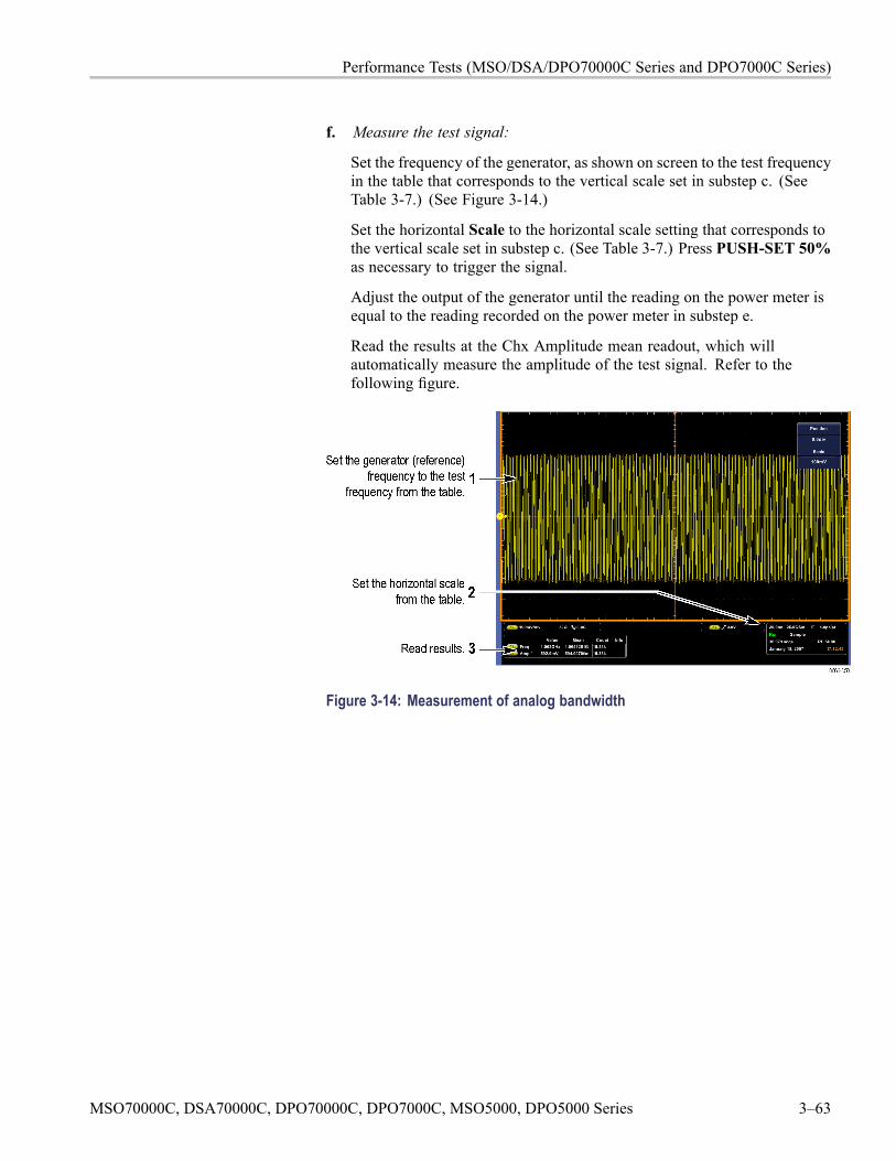
Performance Tests (MSO/DSA/DPO70000C Series and DPO7000C Series)
f. Measure the test signal:
Set the frequency of the generator, as shown on screen to the test frequencyin the table that corresponds to the vertical scale set in substep c. (SeeTable 3-7.) (See Figure 3-14.)
Set the horizontal Scale to the horizontal scale setting that corresponds tothe vertical scale set in substep c. (See Table 3-7.) Press PUSH-SET 50%as necessary to trigger the signal.
Adjust the output of the generator until the reading on the power meter isequal to the reading recorded on the power meter in substep e.
Read the results at the Chx Amplitude mean readout, which willautomatically measure the amplitude of the test signal. Refer to thefollowing figure.
Figure 3-14: Measurement of analog bandwidth
MSO70000C, DSA70000C, DPO70000C, DPO7000C, MSO5000, DPO5000 Series 3–63
Performance Tests (MSO/DSA/DPO70000C Series and DPO7000C Series)
g. Check against limits:
CHECK that the Amplitude mean readout on screen is within thelimits listed in the table for the current vertical scale setting. (SeeTable 3-7.)
Enter the voltage on the test record.
When finished checking, set the horizontal Scale back to the 20 ns.
h. Check remaining vertical scale settings against limits:
Check the remaining vertical scale settings for the channel under testby repeating substeps c through g for each of the remaining scalesettings for the channel under test.
When doing substep f, skip the subparts that turn on the ChxAmplitude mean measurement until you check a new channel.
When selecting a new channel and before doing substep f, touch theClear All button to remove the previous channel measurements.
i. Test all channels: Repeat substeps a through g for all four channels.
3. Disconnect the hookup: Disconnect the test hook up from the input connectorof the channel last tested.
3–64 MSO70000C, DSA70000C, DPO70000C, DPO7000C, MSO5000, DPO5000 Series
Performance Tests (MSO/DSA/DPO70000C Series and DPO7000C Series)
Check Channel Bandwidth,≥ 3.5 GHz models
Equipment Required PrerequisitesOne sine wave generator (Item 9)One level meter and power sensor (Item 10)One power splitter (Item 11)50Ω precision cable 2.92 mm male-to-female(Item 12)One K male-to-male adapter (Item 13)SMA male-to-BNC female adapter (Item 19)
(See page 3-18, Prerequisites.)
1. Install the test hookup and preset the instrument controls:
a. Initialize the instrument:
Press Default Setup.
b. Modify the default settings:
Touch Vertical, select Vertical Setup.
DPO7354C: Touch Termination 50 Ω.
From the Bandwidth drop-down list, select the maximum bandwidthfor your instrument.
Turn the horizontal Scale knob to 40 ns. (DPO7354C: set to 50 ns.)
From the button bar, touch Horiz/Acq and select the Horizontal tab.Select Constant Sample Rate mode. Set the Sample Rate to 250 GS/sor 200 GS/s, depending on instrument setup. (DPO7354C: set to200 GS/s.)
From the button bar, touch Horiz/Acq and select the Acquisition tab.Set the acquisition mode as follows:
Touch Sample.
Set the sampling mode as follows:
Touch the Interpolate IT button.
From the button bar, touchMeasure. Touch Setups Ref Levs; thentouch the Histogram Mode button.
If your instrument has enhanced bandwidth, from the toolbar, touchVertical and check Force Constant Sample Rate (Digital filtersensured). Select Apply to All Channels.
c. Hook up the test-signal source: Connect the sine wave output of the sinewave generator to Ch 1 through a power splitter. Connect the powersensor of the power meter to the power splitter. Set the output of thegenerator to a reference frequency of 50 MHz. (See Figure 3-15.)
MSO70000C, DSA70000C, DPO70000C, DPO7000C, MSO5000, DPO5000 Series 3–65
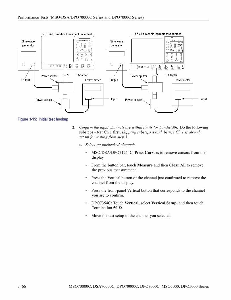
Performance Tests (MSO/DSA/DPO70000C Series and DPO7000C Series)
Figure 3-15: Initial test hookup
2. Confirm the input channels are within limits for bandwidth: Do the followingsubsteps - test Ch 1 first, skipping substeps a and bsince Ch 1 is alreadyset up for testing from step 1.
a. Select an unchecked channel:
MSO/DSA/DPO71254C: Press Cursors to remove cursors from thedisplay.
From the button bar, touchMeasure and then Clear All to removethe previous measurement.
Press the Vertical button of the channel just confirmed to remove thechannel from the display.
Press the front-panel Vertical button that corresponds to the channelyou are to confirm.
DPO7354C: Touch Vertical, select Vertical Setup, and then touchTermination 50 Ω.
Move the test setup to the channel you selected.
3–66 MSO70000C, DSA70000C, DPO70000C, DPO7000C, MSO5000, DPO5000 Series
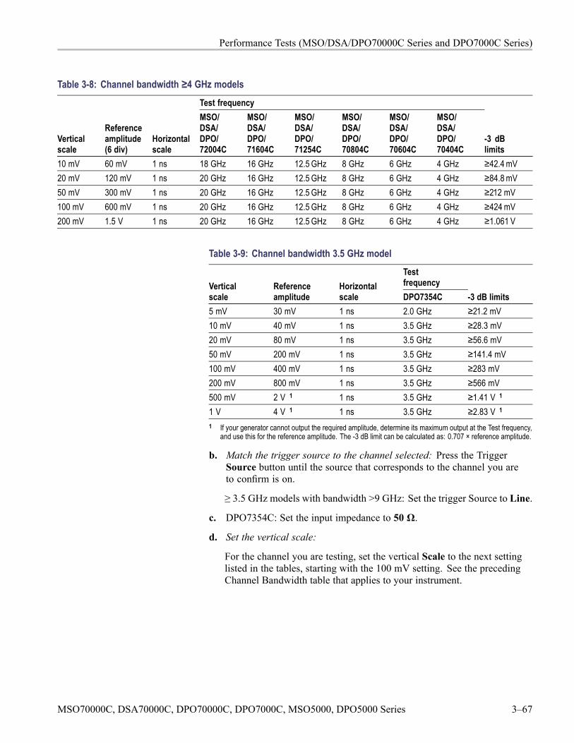
Performance Tests (MSO/DSA/DPO70000C Series and DPO7000C Series)
Table 3-8: Channel bandwidth ≥4 GHz modelsTest frequency
Verticalscale
Referenceamplitude(6 div)
Horizontalscale
MSO/DSA/DPO/72004C
MSO/DSA/DPO/71604C
MSO/DSA/DPO/71254C
MSO/DSA/DPO/70804C
MSO/DSA/DPO/70604C
MSO/DSA/DPO/70404C
-3 dBlimits
10 mV 60 mV 1 ns 18 GHz 16 GHz 12.5 GHz 8 GHz 6 GHz 4 GHz ≥42.4 mV20 mV 120 mV 1 ns 20 GHz 16 GHz 12.5 GHz 8 GHz 6 GHz 4 GHz ≥84.8 mV50 mV 300 mV 1 ns 20 GHz 16 GHz 12.5 GHz 8 GHz 6 GHz 4 GHz ≥212 mV100 mV 600 mV 1 ns 20 GHz 16 GHz 12.5 GHz 8 GHz 6 GHz 4 GHz ≥424 mV200 mV 1.5 V 1 ns 20 GHz 16 GHz 12.5 GHz 8 GHz 6 GHz 4 GHz ≥1.061 V
Table 3-9: Channel bandwidth 3.5 GHz modelTestfrequencyVertical
scaleReferenceamplitude
Horizontalscale DPO7354C -3 dB limits
5 mV 30 mV 1 ns 2.0 GHz ≥21.2 mV10 mV 40 mV 1 ns 3.5 GHz ≥28.3 mV20 mV 80 mV 1 ns 3.5 GHz ≥56.6 mV50 mV 200 mV 1 ns 3.5 GHz ≥141.4 mV100 mV 400 mV 1 ns 3.5 GHz ≥283 mV200 mV 800 mV 1 ns 3.5 GHz ≥566 mV500 mV 2 V 1 1 ns 3.5 GHz ≥1.41 V 1
1 V 4 V 1 1 ns 3.5 GHz ≥2.83 V 1
1 If your generator cannot output the required amplitude, determine its maximum output at the Test frequency,and use this for the reference amplitude. The -3 dB limit can be calculated as: 0.707 × reference amplitude.
b. Match the trigger source to the channel selected: Press the TriggerSource button until the source that corresponds to the channel you areto confirm is on.
≥ 3.5 GHz models with bandwidth >9 GHz: Set the trigger Source to Line.
c. DPO7354C: Set the input impedance to 50 Ω.
d. Set the vertical scale:
For the channel you are testing, set the vertical Scale to the next settinglisted in the tables, starting with the 100 mV setting. See the precedingChannel Bandwidth table that applies to your instrument.
MSO70000C, DSA70000C, DPO70000C, DPO7000C, MSO5000, DPO5000 Series 3–67
Performance Tests (MSO/DSA/DPO70000C Series and DPO7000C Series)
e. Set the trigger coupling: From the button bar, touch Trigger and selectCoupling DC.
f. Display the test signal: Do the following subparts to first display thereference signal and then the test signal.
MSO/DSA/DPO71254C: From the button bar, touch Cursors. TouchCursor Type H Bars.
From the button bar touchMeasure; then select the Time tab.
Touch the Freq button to measure the frequency of the current channel.
Select the Ampl tab. Touch the Amplitude button.
From the Annotation drop-down list, select None.
Touch the Statistics button, then touch theMean button.
Touch the X (Close) button.
Set the generator output so the Chx Amplitude mean readout equalsthe reference amplitude. See the preceding Channel Bandwidth tablethat applies to your oscilloscope model. This corresponds to thevertical scale set in substep d.
Record the reading on the power meter.
Set the trigger as follows:
Press the front-panel Push-Set 50% button as necessary to trigger astable display. At full bandwidth, you may also want to make small,manual adjustments to the trigger level. You can use the TriggerLevel knob to do this.
NOTE. If you are using Line trigger, the test signal is not shown as a stabledisplay.
g. Measure the test signal:
MSO/DSA/DPO71254C: Set the frequency of the generator to thetest frequency in the tables that corresponds to the vertical scale setin substep d.
All instruments except the MSO/DSA/DPO71254C: Set the frequencyof the generator, as shown on screen, to the test frequency in the tablesthat corresponds to the vertical scale set in substep d.
Set the horizontal Scale to the horizontal scale setting in the tables thatcorresponds to the vertical scale set in substep d. Press PUSH-SET50% as necessary to trigger the signal.
3–68 MSO70000C, DSA70000C, DPO70000C, DPO7000C, MSO5000, DPO5000 Series
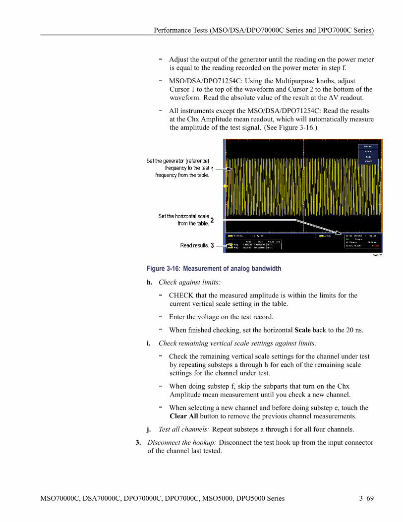
Performance Tests (MSO/DSA/DPO70000C Series and DPO7000C Series)
Adjust the output of the generator until the reading on the power meteris equal to the reading recorded on the power meter in step f.
MSO/DSA/DPO71254C: Using the Multipurpose knobs, adjustCursor 1 to the top of the waveform and Cursor 2 to the bottom of thewaveform. Read the absolute value of the result at the ΔV readout.
All instruments except the MSO/DSA/DPO71254C: Read the resultsat the Chx Amplitude mean readout, which will automatically measurethe amplitude of the test signal. (See Figure 3-16.)
Figure 3-16: Measurement of analog bandwidth
h. Check against limits:
CHECK that the measured amplitude is within the limits for thecurrent vertical scale setting in the table.
Enter the voltage on the test record.
When finished checking, set the horizontal Scale back to the 20 ns.
i. Check remaining vertical scale settings against limits:
Check the remaining vertical scale settings for the channel under testby repeating substeps a through h for each of the remaining scalesettings for the channel under test.
When doing substep f, skip the subparts that turn on the ChxAmplitude mean measurement until you check a new channel.
When selecting a new channel and before doing substep e, touch theClear All button to remove the previous channel measurements.
j. Test all channels: Repeat substeps a through i for all four channels.
3. Disconnect the hookup: Disconnect the test hook up from the input connectorof the channel last tested.
MSO70000C, DSA70000C, DPO70000C, DPO7000C, MSO5000, DPO5000 Series 3–69
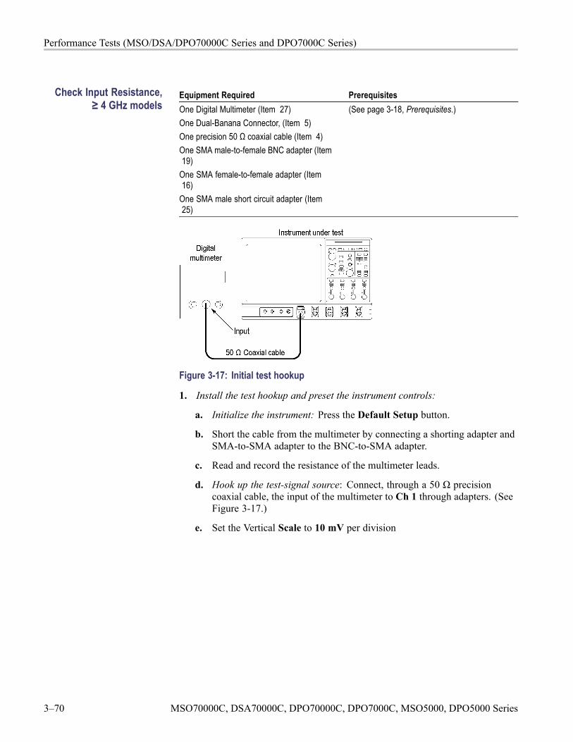
Performance Tests (MSO/DSA/DPO70000C Series and DPO7000C Series)
Check Input Resistance,≥ 4 GHz models
Equipment Required PrerequisitesOne Digital Multimeter (Item 27)One Dual-Banana Connector, (Item 5)One precision 50 Ω coaxial cable (Item 4)One SMA male-to-female BNC adapter (Item19)
One SMA female-to-female adapter (Item16)
One SMA male short circuit adapter (Item25)
(See page 3-18, Prerequisites.)
Figure 3-17: Initial test hookup
1. Install the test hookup and preset the instrument controls:
a. Initialize the instrument: Press the Default Setup button.
b. Short the cable from the multimeter by connecting a shorting adapter andSMA-to-SMA adapter to the BNC-to-SMA adapter.
c. Read and record the resistance of the multimeter leads.
d. Hook up the test-signal source: Connect, through a 50 Ω precisioncoaxial cable, the input of the multimeter to Ch 1 through adapters. (SeeFigure 3-17.)
e. Set the Vertical Scale to 10 mV per division
3–70 MSO70000C, DSA70000C, DPO70000C, DPO7000C, MSO5000, DPO5000 Series
Performance Tests (MSO/DSA/DPO70000C Series and DPO7000C Series)
2. Check input impedance against limits:
a. Measure the impedance: Read and record the measured impedance.
b. Remove the dual banana connector from the digital multimeter (DMM),turn it 180 degrees and reinsert it in the DMM input.
c. Measure the impedance: Read and record the measured impedance.
d. Add the two measurements and divide the result by 2.
e. Subtract the resistance of the multimeter leads from the average that youcalculated.
f. Enter the result on the test record.
g. Check - The measurement is within the limits specified in the test record.
3. Set the Vertical Scale to 100 mV per division and repeat step 2.
4. Repeat steps 2 through 3 for the remaining input channels:
a. Move the test setup to an unchecked input channel.
b. Set the Vertical Scale of the channel to 10 mV per division.
c. Repeat steps 2 through 3.
5. Disconnect the hookup: Disconnect the equipment from the instrument.
MSO70000C, DSA70000C, DPO70000C, DPO7000C, MSO5000, DPO5000 Series 3–71
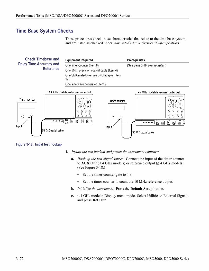
Performance Tests (MSO/DSA/DPO70000C Series and DPO7000C Series)
Time Base System ChecksThese procedures check those characteristics that relate to the time base systemand are listed as checked under Warranted Characteristics in Specifications.
Check Timebase andDelay Time Accuracy and
Reference
Equipment Required PrerequisitesOne timer-counter (Item 8)One 50 Ω, precision coaxial cable (Item 4)One SMA male-to-female BNC adapter (Item19)One sine wave generator (Item 9)
(See page 3-18, Prerequisites.)
Figure 3-18: Initial test hookup
1. Install the test hookup and preset the instrument controls:
a. Hook up the test-signal source: Connect the input of the timer-counterto AUX Out (< 4 GHz models) or reference output (≥ 4 GHz models).(See Figure 3-18.)
Set the timer-counter gate to 1 s.
Set the timer-counter to count the 10 MHz reference output.
b. Initialize the instrument: Press the Default Setup button.
c. < 4 GHz models: Display menu mode. Select Utilities > External Signalsand press Ref Out.
3–72 MSO70000C, DSA70000C, DPO70000C, DPO7000C, MSO5000, DPO5000 Series
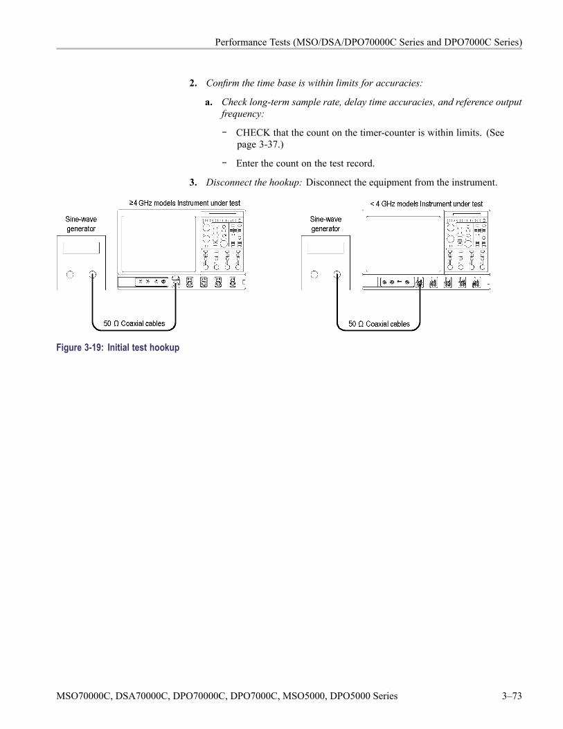
Performance Tests (MSO/DSA/DPO70000C Series and DPO7000C Series)
2. Confirm the time base is within limits for accuracies:
a. Check long-term sample rate, delay time accuracies, and reference outputfrequency:
CHECK that the count on the timer-counter is within limits. (Seepage 3-37.)
Enter the count on the test record.
3. Disconnect the hookup: Disconnect the equipment from the instrument.
Figure 3-19: Initial test hookup
MSO70000C, DSA70000C, DPO70000C, DPO7000C, MSO5000, DPO5000 Series 3–73
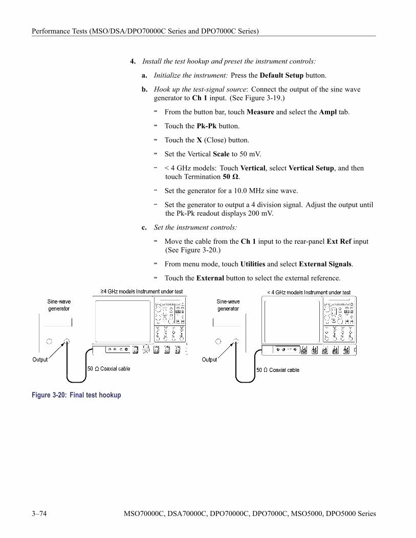
Performance Tests (MSO/DSA/DPO70000C Series and DPO7000C Series)
4. Install the test hookup and preset the instrument controls:
a. Initialize the instrument: Press the Default Setup button.
b. Hook up the test-signal source: Connect the output of the sine wavegenerator to Ch 1 input. (See Figure 3-19.)
From the button bar, touchMeasure and select the Ampl tab.
Touch the Pk-Pk button.
Touch the X (Close) button.
Set the Vertical Scale to 50 mV.
< 4 GHz models: Touch Vertical, select Vertical Setup, and thentouch Termination 50 Ω.
Set the generator for a 10.0 MHz sine wave.
Set the generator to output a 4 division signal. Adjust the output untilthe Pk-Pk readout displays 200 mV.
c. Set the instrument controls:
Move the cable from the Ch 1 input to the rear-panel Ext Ref input(See Figure 3-20.)
From menu mode, touch Utilities and select External Signals.
Touch the External button to select the external reference.
Figure 3-20: Final test hookup
3–74 MSO70000C, DSA70000C, DPO70000C, DPO7000C, MSO5000, DPO5000 Series
Performance Tests (MSO/DSA/DPO70000C Series and DPO7000C Series)
5. Confirm external reference:
a. Perform a signal path compensation:
Touch Utilities and select Instrument Calibration.
Touch Run SPC (Calibrate on some instruments) and wait for thesignal path compensation to finish.
b. Check the completion status: Enter the pass/fail status in the test record.If the Status is Fail, refer the instrument to qualified service personnel.
6. Disconnect the hookup:
a. Disconnect all test equipment from the instrument.
b. Set the instrument controls:
From menu mode, touch Utilities and select External Signals.
Touch the Internal button to select the internal reference.
c. Perform a signal path compensation:
Touch Utilities and select Instrument Calibration.
Touch Run SPC (Calibrate on some instruments) and wait for thesignal path compensation to finish.
MSO70000C, DSA70000C, DPO70000C, DPO7000C, MSO5000, DPO5000 Series 3–75
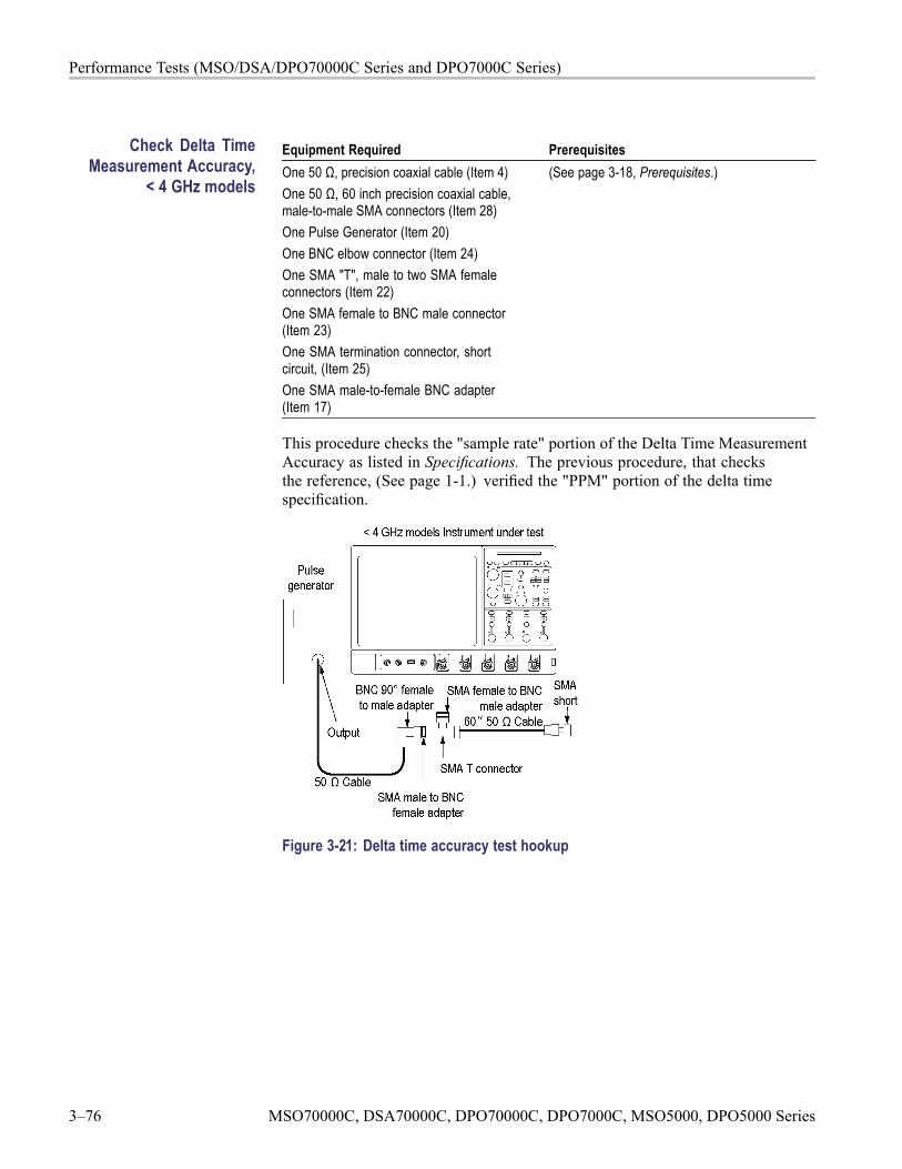
Performance Tests (MSO/DSA/DPO70000C Series and DPO7000C Series)
Check Delta TimeMeasurement Accuracy,
< 4 GHz models
Equipment Required PrerequisitesOne 50 Ω, precision coaxial cable (Item 4)One 50 Ω, 60 inch precision coaxial cable,male-to-male SMA connectors (Item 28)One Pulse Generator (Item 20)One BNC elbow connector (Item 24)One SMA "T", male to two SMA femaleconnectors (Item 22)One SMA female to BNC male connector(Item 23)One SMA termination connector, shortcircuit, (Item 25)One SMA male-to-female BNC adapter(Item 17)
(See page 3-18, Prerequisites.)
This procedure checks the "sample rate" portion of the Delta Time MeasurementAccuracy as listed in Specifications. The previous procedure, that checksthe reference, (See page 1-1.) verified the "PPM" portion of the delta timespecification.
Figure 3-21: Delta time accuracy test hookup
3–76 MSO70000C, DSA70000C, DPO70000C, DPO7000C, MSO5000, DPO5000 Series
Performance Tests (MSO/DSA/DPO70000C Series and DPO7000C Series)
1. Install the test hookup and preset the instrument controls:
a. Initialize the instrument: Press the Default Setup button.
b. Hook up the pulse generator:
< 4 GHz models: Touch Vertical, select Vertical Setup, and thentouch Termination 50 Ω.
Connect the pulse generator output to a 50 Ω precision coaxial cablefollowed by a 90° right-angle female to male SMA adapter. Theadapter is connected to one side of the female SMA T connector.The other side of the SMA T is connected to a 60 inch 50 Ω coaxialcable. Connect the SMA short, to the remaining end of the cable.Now connect the male SMA T connector to Ch 1 through an SMAfemale to BNC male adapter.
Set the pulse generator output for a positive-going pulse with arise-time as shown in the table for your instrument, and for the fastestpossible repetition rate (at least 1 kHz). (See Table 3-10 on page 3-78.)
Set the pulse generator output for about 500 mV. (This amplitude canbe adjusted later to get a 5-division pulse on screen.)
c. Modify the initialized front-panel control settings:
Power on the pulse generator.
Touch Utilities, select User Preferences, select the Units tab, andthen select the 1-2-5 button.
Readjust the Trigger Level knob so the trigger level is about 50% ofthe rising edge of the positive pulse.
Press Autoset. You may see both positive and negative pulses. Adjustthe Trigger Level knob so the trigger level is about 50% of the risingedge of the positive pulse.
From the button bar, touch the Horiz/Acq button and select theAcquisition tab. Press the RT button to turn on Real Time Only.
< 4 GHz models: Set the horizontal SCALE as indicated in thefollowing table.
MSO70000C, DSA70000C, DPO70000C, DPO7000C, MSO5000, DPO5000 Series 3–77
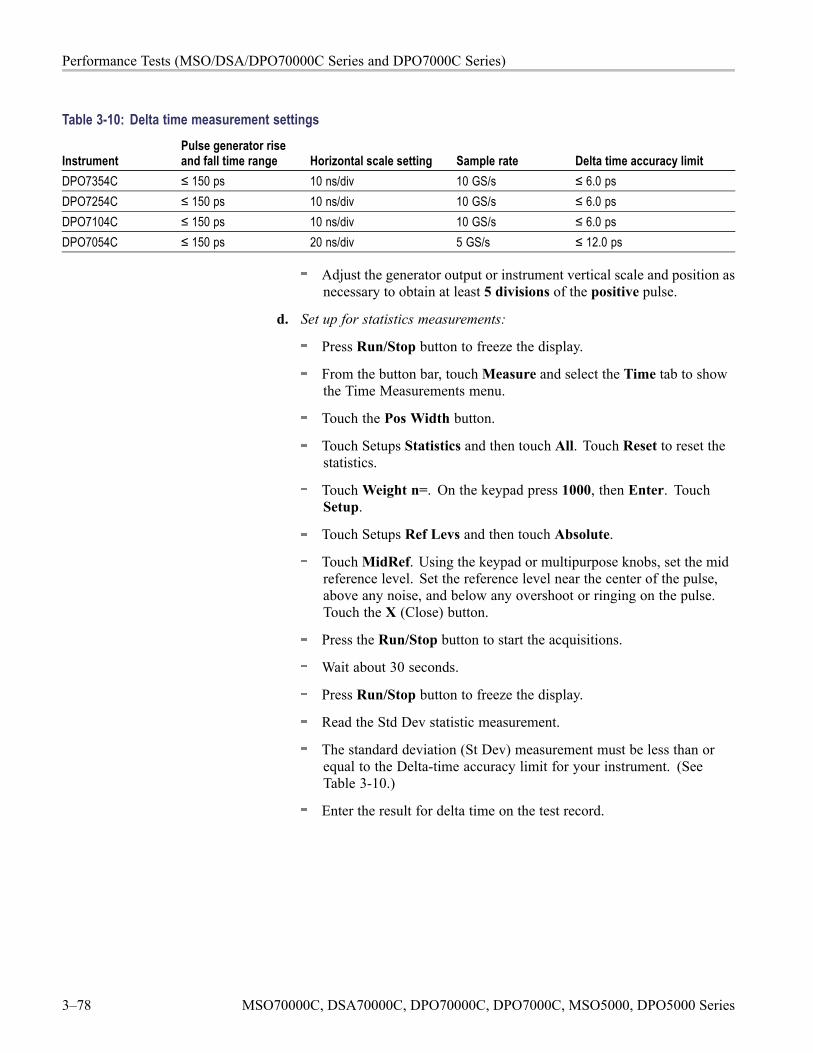
Performance Tests (MSO/DSA/DPO70000C Series and DPO7000C Series)
Table 3-10: Delta time measurement settings
InstrumentPulse generator riseand fall time range Horizontal scale setting Sample rate Delta time accuracy limit
DPO7354C ≤ 150 ps 10 ns/div 10 GS/s ≤ 6.0 psDPO7254C ≤ 150 ps 10 ns/div 10 GS/s ≤ 6.0 psDPO7104C ≤ 150 ps 10 ns/div 10 GS/s ≤ 6.0 psDPO7054C ≤ 150 ps 20 ns/div 5 GS/s ≤ 12.0 ps
Adjust the generator output or instrument vertical scale and position asnecessary to obtain at least 5 divisions of the positive pulse.
d. Set up for statistics measurements:
Press Run/Stop button to freeze the display.
From the button bar, touchMeasure and select the Time tab to showthe Time Measurements menu.
Touch the Pos Width button.
Touch Setups Statistics and then touch All. Touch Reset to reset thestatistics.
TouchWeight n=. On the keypad press 1000, then Enter. TouchSetup.
Touch Setups Ref Levs and then touch Absolute.
TouchMidRef. Using the keypad or multipurpose knobs, set the midreference level. Set the reference level near the center of the pulse,above any noise, and below any overshoot or ringing on the pulse.Touch the X (Close) button.
Press the Run/Stop button to start the acquisitions.
Wait about 30 seconds.
Press Run/Stop button to freeze the display.
Read the Std Dev statistic measurement.
The standard deviation (St Dev) measurement must be less than orequal to the Delta-time accuracy limit for your instrument. (SeeTable 3-10.)
Enter the result for delta time on the test record.
3–78 MSO70000C, DSA70000C, DPO70000C, DPO7000C, MSO5000, DPO5000 Series
Performance Tests (MSO/DSA/DPO70000C Series and DPO7000C Series)
e. Repeat for all other channels:
Note the vertical scale setting of the channel just confirmed.
Press the Vertical channel button for the channel just confirmed toremove the channel from display.
TouchMeasure and then Clear All to remove the measurement.
Press the front-panel button that corresponds to the channel you areto confirm.
Set vertical scale to the setting noted in step e, first bullet.
Press the Trigger Source button to toggle the source to the channelselected.
< 4 GHz models: Touch Vertical, select Vertical Setup, and thentouch Termination 50 Ω.
Move the test hookup to the channel you selected.
Press Run/Stop button to start the display.
Repeat step d.
Touch Utilities, select User Preferences, select the Units tab, andthen select the 1-2-3 button.
2. Disconnect all test equipment from the instrument.
MSO70000C, DSA70000C, DPO70000C, DPO7000C, MSO5000, DPO5000 Series 3–79
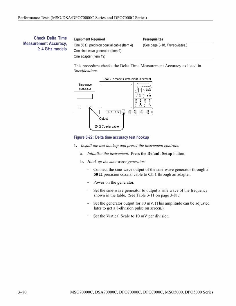
Performance Tests (MSO/DSA/DPO70000C Series and DPO7000C Series)
Check Delta TimeMeasurement Accuracy,
≥ 4 GHz models
Equipment Required PrerequisitesOne 50 Ω, precision coaxial cable (Item 4)One sine-wave generator (Item 9)One adapter (Item 19)
(See page 3-18, Prerequisites.)
This procedure checks the Delta Time Measurement Accuracy as listed inSpecifications.
Figure 3-22: Delta time accuracy test hookup
1. Install the test hookup and preset the instrument controls:
a. Initialize the instrument: Press the Default Setup button.
b. Hook up the sine-wave generator:
Connect the sine-wave output of the sine-wave generator through a50 Ω precision coaxial cable to Ch 1 through an adapter.
Power on the generator.
Set the sine-wave generator to output a sine wave of the frequencyshown in the table. (See Table 3-11 on page 3-81.)
Set the generator output for 80 mV. (This amplitude can be adjustedlater to get a 8-division pulse on screen.)
Set the Vertical Scale to 10 mV per division.
3–80 MSO70000C, DSA70000C, DPO70000C, DPO7000C, MSO5000, DPO5000 Series
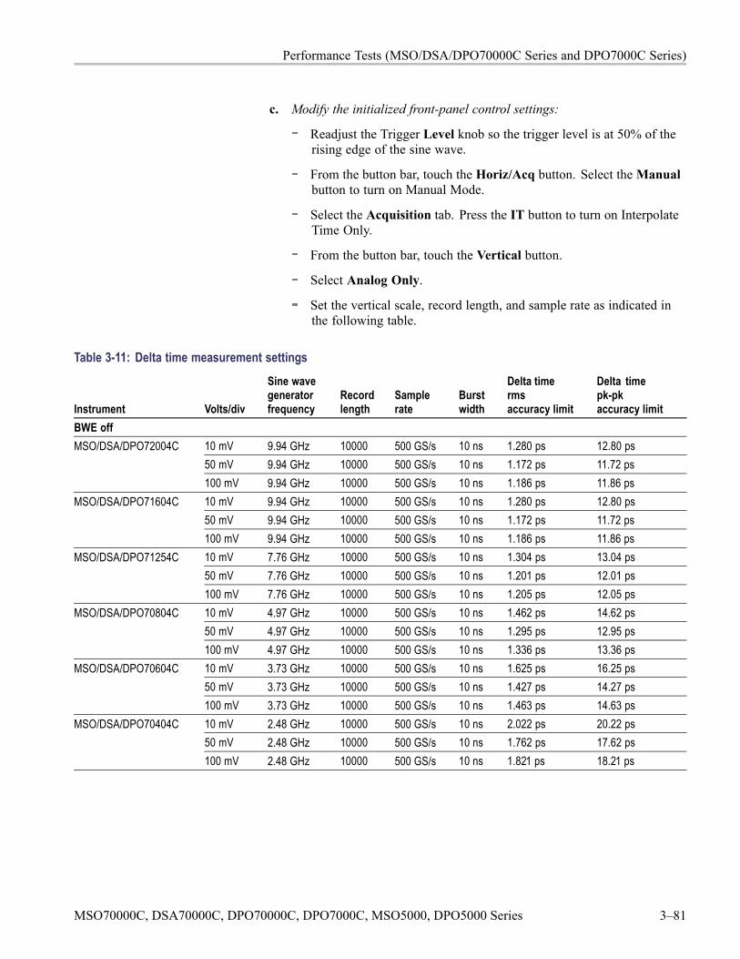
Performance Tests (MSO/DSA/DPO70000C Series and DPO7000C Series)
c. Modify the initialized front-panel control settings:
Readjust the Trigger Level knob so the trigger level is at 50% of therising edge of the sine wave.
From the button bar, touch the Horiz/Acq button. Select theManualbutton to turn on Manual Mode.
Select the Acquisition tab. Press the IT button to turn on InterpolateTime Only.
From the button bar, touch the Vertical button.
Select Analog Only.
Set the vertical scale, record length, and sample rate as indicated inthe following table.
Table 3-11: Delta time measurement settings
Instrument Volts/div
Sine wavegeneratorfrequency
Recordlength
Samplerate
Burstwidth
Delta timermsaccuracy limit
Delta timepk-pkaccuracy limit
BWE off10 mV 9.94 GHz 10000 500 GS/s 10 ns 1.280 ps 12.80 ps50 mV 9.94 GHz 10000 500 GS/s 10 ns 1.172 ps 11.72 ps
MSO/DSA/DPO72004C
100 mV 9.94 GHz 10000 500 GS/s 10 ns 1.186 ps 11.86 ps10 mV 9.94 GHz 10000 500 GS/s 10 ns 1.280 ps 12.80 ps50 mV 9.94 GHz 10000 500 GS/s 10 ns 1.172 ps 11.72 ps
MSO/DSA/DPO71604C
100 mV 9.94 GHz 10000 500 GS/s 10 ns 1.186 ps 11.86 ps10 mV 7.76 GHz 10000 500 GS/s 10 ns 1.304 ps 13.04 ps50 mV 7.76 GHz 10000 500 GS/s 10 ns 1.201 ps 12.01 ps
MSO/DSA/DPO71254C
100 mV 7.76 GHz 10000 500 GS/s 10 ns 1.205 ps 12.05 ps10 mV 4.97 GHz 10000 500 GS/s 10 ns 1.462 ps 14.62 ps50 mV 4.97 GHz 10000 500 GS/s 10 ns 1.295 ps 12.95 ps
MSO/DSA/DPO70804C
100 mV 4.97 GHz 10000 500 GS/s 10 ns 1.336 ps 13.36 ps10 mV 3.73 GHz 10000 500 GS/s 10 ns 1.625 ps 16.25 ps50 mV 3.73 GHz 10000 500 GS/s 10 ns 1.427 ps 14.27 ps
MSO/DSA/DPO70604C
100 mV 3.73 GHz 10000 500 GS/s 10 ns 1.463 ps 14.63 ps10 mV 2.48 GHz 10000 500 GS/s 10 ns 2.022 ps 20.22 ps50 mV 2.48 GHz 10000 500 GS/s 10 ns 1.762 ps 17.62 ps
MSO/DSA/DPO70404C
100 mV 2.48 GHz 10000 500 GS/s 10 ns 1.821 ps 18.21 ps
MSO70000C, DSA70000C, DPO70000C, DPO7000C, MSO5000, DPO5000 Series 3–81
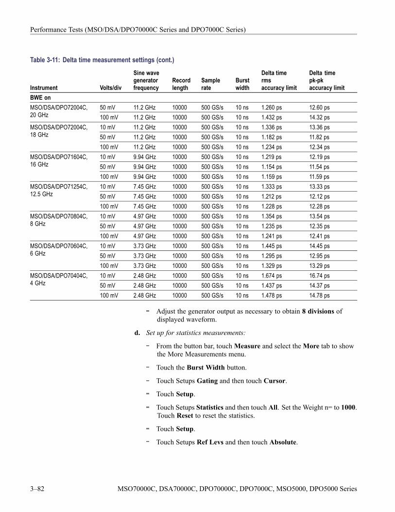
Performance Tests (MSO/DSA/DPO70000C Series and DPO7000C Series)
Table 3-11: Delta time measurement settings (cont.)
Instrument Volts/div
Sine wavegeneratorfrequency
Recordlength
Samplerate
Burstwidth
Delta timermsaccuracy limit
Delta timepk-pkaccuracy limit
BWE on50 mV 11.2 GHz 10000 500 GS/s 10 ns 1.260 ps 12.60 psMSO/DSA/DPO72004C,
20 GHz 100 mV 11.2 GHz 10000 500 GS/s 10 ns 1.432 ps 14.32 ps10 mV 11.2 GHz 10000 500 GS/s 10 ns 1.336 ps 13.36 ps50 mV 11.2 GHz 10000 500 GS/s 10 ns 1.182 ps 11.82 ps
MSO/DSA/DPO72004C,18 GHz
100 mV 11.2 GHz 10000 500 GS/s 10 ns 1.234 ps 12.34 ps10 mV 9.94 GHz 10000 500 GS/s 10 ns 1.219 ps 12.19 ps50 mV 9.94 GHz 10000 500 GS/s 10 ns 1.154 ps 11.54 ps
MSO/DSA/DPO71604C,16 GHz
100 mV 9.94 GHz 10000 500 GS/s 10 ns 1.159 ps 11.59 ps10 mV 7.45 GHz 10000 500 GS/s 10 ns 1.333 ps 13.33 ps50 mV 7.45 GHz 10000 500 GS/s 10 ns 1.212 ps 12.12 ps
MSO/DSA/DPO71254C,12.5 GHz
100 mV 7.45 GHz 10000 500 GS/s 10 ns 1.228 ps 12.28 ps10 mV 4.97 GHz 10000 500 GS/s 10 ns 1.354 ps 13.54 ps50 mV 4.97 GHz 10000 500 GS/s 10 ns 1.235 ps 12.35 ps
MSO/DSA/DPO70804C,8 GHz
100 mV 4.97 GHz 10000 500 GS/s 10 ns 1.241 ps 12.41 ps10 mV 3.73 GHz 10000 500 GS/s 10 ns 1.445 ps 14.45 ps50 mV 3.73 GHz 10000 500 GS/s 10 ns 1.295 ps 12.95 ps
MSO/DSA/DPO70604C,6 GHz
100 mV 3.73 GHz 10000 500 GS/s 10 ns 1.329 ps 13.29 ps10 mV 2.48 GHz 10000 500 GS/s 10 ns 1.674 ps 16.74 ps50 mV 2.48 GHz 10000 500 GS/s 10 ns 1.437 ps 14.37 ps
MSO/DSA/DPO70404C,4 GHz
100 mV 2.48 GHz 10000 500 GS/s 10 ns 1.478 ps 14.78 ps
Adjust the generator output as necessary to obtain 8 divisions ofdisplayed waveform.
d. Set up for statistics measurements:
From the button bar, touchMeasure and select theMore tab to showthe More Measurements menu.
Touch the Burst Width button.
Touch Setups Gating and then touch Cursor.
Touch Setup.
Touch Setups Statistics and then touch All. Set the Weight n= to 1000.Touch Reset to reset the statistics.
Touch Setup.
Touch Setups Ref Levs and then touch Absolute.
3–82 MSO70000C, DSA70000C, DPO70000C, DPO7000C, MSO5000, DPO5000 Series
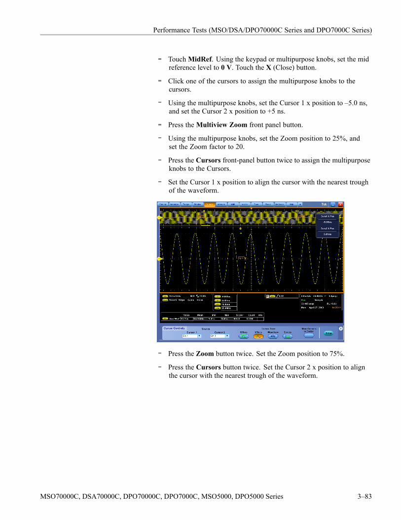
Performance Tests (MSO/DSA/DPO70000C Series and DPO7000C Series)
TouchMidRef. Using the keypad or multipurpose knobs, set the midreference level to 0 V. Touch the X (Close) button.
Click one of the cursors to assign the multipurpose knobs to thecursors.
Using the multipurpose knobs, set the Cursor 1 x position to –5.0 ns,and set the Cursor 2 x position to +5 ns.
Press theMultiview Zoom front panel button.
Using the multipurpose knobs, set the Zoom position to 25%, andset the Zoom factor to 20.
Press the Cursors front-panel button twice to assign the multipurposeknobs to the Cursors.
Set the Cursor 1 x position to align the cursor with the nearest troughof the waveform.
Press the Zoom button twice. Set the Zoom position to 75%.
Press the Cursors button twice. Set the Cursor 2 x position to alignthe cursor with the nearest trough of the waveform.
MSO70000C, DSA70000C, DPO70000C, DPO7000C, MSO5000, DPO5000 Series 3–83
Performance Tests (MSO/DSA/DPO70000C Series and DPO7000C Series)
e. Read the measurement:
Press the Clear button. Allow approximately 1000 acquisitions toaccumulate, then press Run/Stop.
Read the Std Dev statistic measurement.
Enter the time on the test record.
The standard deviation (St Dev) measurement must be less than orequal to the rms Delta-time accuracy limit for your instrument andbandwidth setting. (See Table 3-11.)
Read the Max and Min statistic measurements.
Subtract the Max and Min statistic measurements.
Enter the time on the test record.
The absolute value of the difference of the Max and Min measurementsmust be less than or equal to the pk-pk Delta-time accuracy limit foryour instrument and bandwidth setting. (See Table 3-11.)
Press the Run/Stop button.
f. Repeat for all other Volts/div settings in the table:
Set the vertical scale, record length, and sample rate as indicated inthe table.
Repeat step e.
g. Repeat for all other appropriate bandwidths:
Set the sine-wave generator to output the next appropriate frequencyfor your instrument from the table.
For tests with BWE on, from the button bar, touch the Vertical button,and then Select Digital Filters (DSP) Enabled.
Set the vertical scale, record length, and sample rate as indicated inthe table.
Using the Horizontal SCALE and the Multipurpose knobs, adjust theHorizontal SCALE and cursors so that the burst width measurement isas in the table.
Repeat steps e and f.
2. Disconnect all test equipment from the instrument.
3–84 MSO70000C, DSA70000C, DPO70000C, DPO7000C, MSO5000, DPO5000 Series
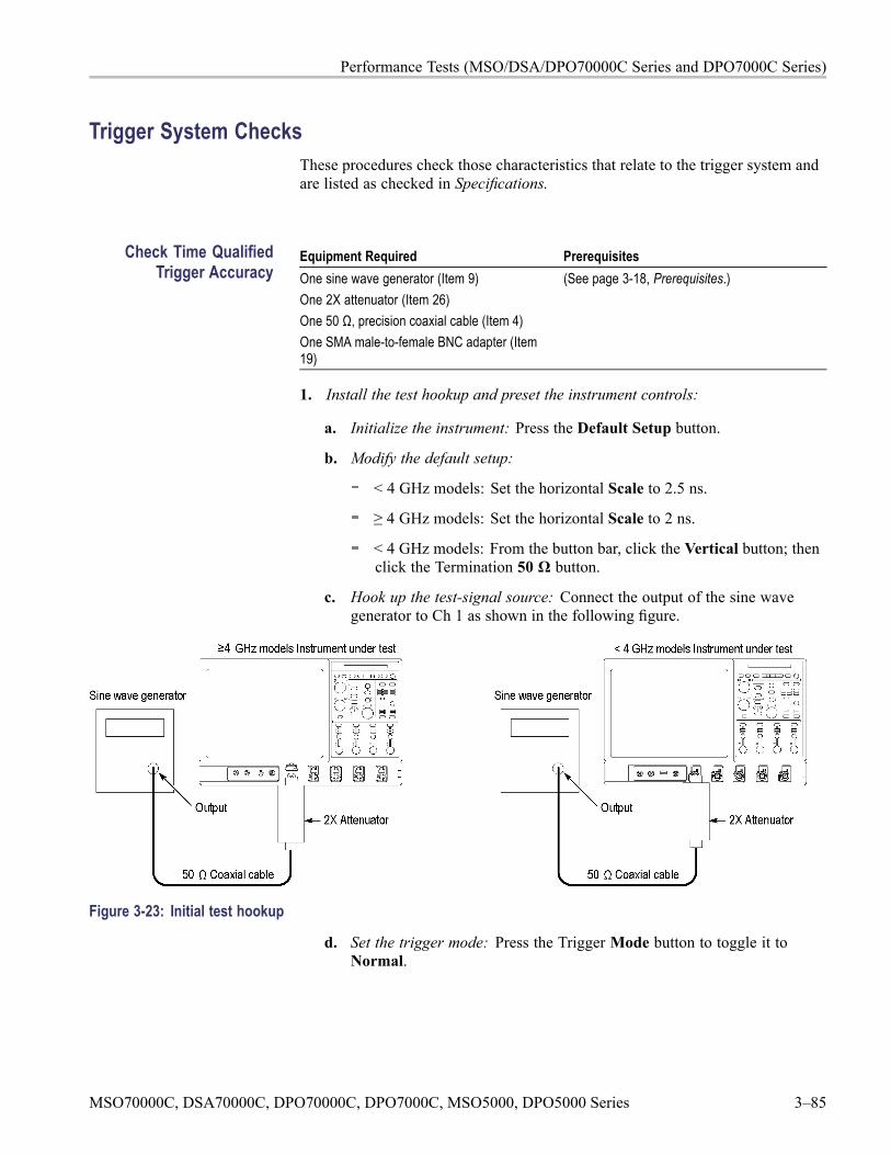
Performance Tests (MSO/DSA/DPO70000C Series and DPO7000C Series)
Trigger System ChecksThese procedures check those characteristics that relate to the trigger system andare listed as checked in Specifications.
Check Time QualifiedTrigger Accuracy
Equipment Required PrerequisitesOne sine wave generator (Item 9)One 2X attenuator (Item 26)One 50 Ω, precision coaxial cable (Item 4)One SMA male-to-female BNC adapter (Item19)
(See page 3-18, Prerequisites.)
1. Install the test hookup and preset the instrument controls:
a. Initialize the instrument: Press the Default Setup button.
b. Modify the default setup:
< 4 GHz models: Set the horizontal Scale to 2.5 ns.
≥ 4 GHz models: Set the horizontal Scale to 2 ns.
< 4 GHz models: From the button bar, click the Vertical button; thenclick the Termination 50 Ω button.
c. Hook up the test-signal source: Connect the output of the sine wavegenerator to Ch 1 as shown in the following figure.
Figure 3-23: Initial test hookup
d. Set the trigger mode: Press the Trigger Mode button to toggle it toNormal.
MSO70000C, DSA70000C, DPO70000C, DPO7000C, MSO5000, DPO5000 Series 3–85
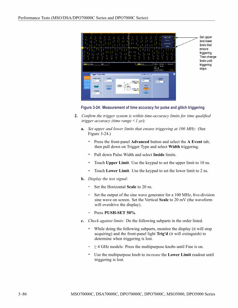
Performance Tests (MSO/DSA/DPO70000C Series and DPO7000C Series)
Figure 3-24: Measurement of time accuracy for pulse and glitch triggering
2. Confirm the trigger system is within time-accuracy limits for time qualifiedtrigger accuracy (time range <1 μs):
a. Set upper and lower limits that ensure triggering at 100 MHz: (SeeFigure 3-24.)
Press the front-panel Advanced button and select the A Event tab;then pull down on Trigger Type and selectWidth triggering.
Pull down Pulse Width and select Inside limits.
Touch Upper Limit. Use the keypad to set the upper limit to 10 ns.
Touch Lower Limit. Use the keypad to set the lower limit to 2 ns.
b. Display the test signal:
Set the Horizontal Scale to 20 ns.
Set the output of the sine wave generator for a 100 MHz, five-divisionsine wave on screen. Set the Vertical Scale to 20 mV (the waveformwill overdrive the display).
Press PUSH-SET 50%.
c. Check against limits: Do the following subparts in the order listed.
While doing the following subparts, monitor the display (it will stopacquiring) and the front-panel light Trig'd (it will extinguish) todetermine when triggering is lost.
≥ 4 GHz models: Press the multipurpose knobs until Fine is on.
Use the multipurpose knob to increase the Lower Limit readout untiltriggering is lost.
3–86 MSO70000C, DSA70000C, DPO70000C, DPO7000C, MSO5000, DPO5000 Series
Performance Tests (MSO/DSA/DPO70000C Series and DPO7000C Series)
CHECK that the Lower Limit readout, after the instrument stopstriggering, is within the following limits:
Model Limit< 4 GHz models 3.5 ns to 6.5 ns≥ 4 GHz models 4.77 ns to 5.23 ns
Enter the time on the test record.
Use the keypad to return the Lower Limit to 2 ns and reestablishtriggering.
Touch Upper Limit; then use the multipurpose knob to slowlydecrease the Upper Limit readout until triggering stops.
CHECK that the Upper Limit readout, after the instrument losestriggering, is within the following limits:
Model Limit< 4 GHz models 3.5 ns to 6.5 ns, inclusive≥ 4 GHz models 4.77 ns to 5.23 ns, inclusive
Enter the time on the test record.
3. Confirm the trigger system is within time-accuracy limits for pulse-glitch orpulse-width triggering (time range ≥1 μs):
a. Set upper and lower limits that ensure triggering at 250 kHz:
Touch Upper Limit. Use the keypad to set the upper limit to 4 μs.
Touch Lower Limit. Use the keypad to set the lower limit to 500 ns.
MSO70000C, DSA70000C, DPO70000C, DPO7000C, MSO5000, DPO5000 Series 3–87
Performance Tests (MSO/DSA/DPO70000C Series and DPO7000C Series)
b. Display the test signal:
< 4 GHz models: Set the Horizontal Scale to 5 μs.
≥ 4 GHz models: Set the Horizontal Scale to 4 μs.
Set the Vertical Scale to 100 mV.
Set the output of the sine wave generator for a 250 kHz, five-divisionsine wave on screen. Set the Vertical Scale to 20 mV (the waveformwill overdrive the display).
Press PUSH-SET 50%.
c. Check against limits: Do the following subparts in the order listed.
≥ 4 GHz models: Press the multipurpose knobs until Fine is on.
Use the multipurpose knob to increase the Lower Limit readout untiltriggering is lost.
CHECK that the Lower Limit readout, after the instrument stopstriggering, is within the following limits:
Model Limit< 4 GHz models 1.9 μs to 2.1 μs, inclusive≥ 4 GHz models 1.9 μs to 2.1 μs, inclusive
Enter the time on the test record.
Use the keypad to return the Lower Limit to 500 ns and reestablishtriggering.
Touch Upper Limit; then use the multipurpose knob to slowlydecrease the Upper Limit readout until triggering stops.
CHECK that the Upper Limit readout, after the instrument losestriggering, is within the following limits:
Model Limit< 4 GHz models 1.9 μs to 2.1 μs, inclusive≥ 4 GHz models 1.9 μs to 2.1 μs, inclusive
Enter the time on the test record.
4. Disconnect the hookup: Disconnect the equipment from the instrument.
3–88 MSO70000C, DSA70000C, DPO70000C, DPO7000C, MSO5000, DPO5000 Series
Performance Tests (MSO/DSA/DPO70000C Series and DPO7000C Series)
Check Sensitivity, EdgeTrigger, DC Coupled
Equipment required PrerequisitesOne leveled sine wave generator (Item 9)Three precision 50 Ω coaxial cables (Item 21)Two SMA female to BNC male adapters (item 23)Three SMA female-to-female adapters (item 16)One 10X attenuator (Item 1)One power splitter (Item 11)Male N-to-BNC adapter (Item 14)One SMA adapter (Item 19)One 5X attenuator (Item 2)One 2X attenuator (Item 26)< 4 GHz models, one 50 Ω termination (item 3)
(See page 3-18, Prerequisites.)
NOTE. The sine wave generator output amplitude must be leveled to within0.35 dB of the reference frequency (10 MHz) through the trigger frequency beingtested.
Refer to the Sine Wave Generator Leveling Procedure if your sine wave generatordoes not have automatic output amplitude leveling. (See page 3-112.)
1. Install the test hookup and preset the instrument controls:
a. Initialize the instrument: Press the Default Setup button.
b. Modify the initialized front-panel control settings:
Set the Horizontal Scale to 20 ns.
< 4 GHz models: Touch Vertical, select Vertical Setup, and thentouch Termination 50 Ω.
Press the TriggerMode button to toggle it to Normal.
From the button bar, touch Horiz/Acq and select the Acquisition tab.
Touch Average and set the number of averages to 16.
Touch the Equivalent ET button.
MSO70000C, DSA70000C, DPO70000C, DPO7000C, MSO5000, DPO5000 Series 3–89
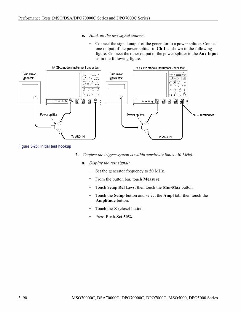
Performance Tests (MSO/DSA/DPO70000C Series and DPO7000C Series)
c. Hook up the test-signal source:
Connect the signal output of the generator to a power splitter. Connectone output of the power splitter to Ch 1 as shown in the followingfigure. Connect the other output of the power splitter to the Aux Inputas in the following figure.
Figure 3-25: Initial test hookup
2. Confirm the trigger system is within sensitivity limits (50 MHz):
a. Display the test signal:
Set the generator frequency to 50 MHz.
From the button bar, touchMeasure.
Touch Setup Ref Levs; then touch theMin-Max button.
Touch the Setup button and select the Ampl tab; then touch theAmplitude button.
Touch the X (close) button.
Press Push-Set 50%.
3–90 MSO70000C, DSA70000C, DPO70000C, DPO7000C, MSO5000, DPO5000 Series
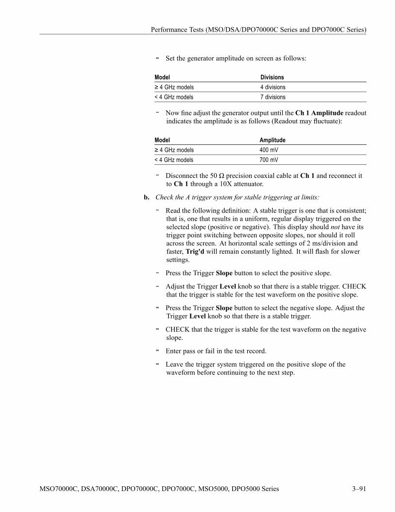
Performance Tests (MSO/DSA/DPO70000C Series and DPO7000C Series)
Set the generator amplitude on screen as follows:
Model Divisions≥ 4 GHz models 4 divisions< 4 GHz models 7 divisions
Now fine adjust the generator output until the Ch 1 Amplitude readoutindicates the amplitude is as follows (Readout may fluctuate):
Model Amplitude≥ 4 GHz models 400 mV< 4 GHz models 700 mV
Disconnect the 50 Ω precision coaxial cable at Ch 1 and reconnect itto Ch 1 through a 10X attenuator.
b. Check the A trigger system for stable triggering at limits:
Read the following definition: A stable trigger is one that is consistent;that is, one that results in a uniform, regular display triggered on theselected slope (positive or negative). This display should not have itstrigger point switching between opposite slopes, nor should it rollacross the screen. At horizontal scale settings of 2 ms/division andfaster, Trig'd will remain constantly lighted. It will flash for slowersettings.
Press the Trigger Slope button to select the positive slope.
Adjust the Trigger Level knob so that there is a stable trigger. CHECKthat the trigger is stable for the test waveform on the positive slope.
Press the Trigger Slope button to select the negative slope. Adjust theTrigger Level knob so that there is a stable trigger.
CHECK that the trigger is stable for the test waveform on the negativeslope.
Enter pass or fail in the test record.
Leave the trigger system triggered on the positive slope of thewaveform before continuing to the next step.
MSO70000C, DSA70000C, DPO70000C, DPO7000C, MSO5000, DPO5000 Series 3–91
Performance Tests (MSO/DSA/DPO70000C Series and DPO7000C Series)
Figure 3-26: Measurement of trigger sensitivity - 50 MHz results shown
c. ≥ 4 GHz models: Check B trigger system for stable triggering at limits:Do the following subparts in the order listed.
From the button bar touch Trig, select the A Event tab, and set theSource to Line.
Select the A->B Seq tab, and touch the A then B Trig After Timebutton.
Select the B Event tab, and touch the Set To 50% button.
CHECK that a stable trigger is obtained for the test waveform for boththe positive and negative slopes of the waveform. Use the TriggerLevel knob to stabilize the A trigger. Touch Level and use the keypador the multipurpose knob/Fine button to stabilize the B trigger. Touchone of the Slope buttons to switch between trigger slopes. (SeeFigure 3-26 on page 3-92.)
Enter pass or fail in the test record.
Leave the Delayed trigger system triggered on the positive slope ofthe waveform before continuing to the next step. Also, return to theA trigger: select the A->B Seq tab and touch the A->B Sequence AOnly button. Then select the A Event tab.
Select the A Event tab, and set the Source to CH1.
Press the X (Close button).
3–92 MSO70000C, DSA70000C, DPO70000C, DPO7000C, MSO5000, DPO5000 Series
Performance Tests (MSO/DSA/DPO70000C Series and DPO7000C Series)
3. Confirm the AUX Trigger input (at 50 MHz):
a. Display the test signal:
Remove the 10X attenuator and reconnect the cable to Ch 1.
Set the signal amplitude as follows: 2.5 divisions
Now fine adjust the generator output until the Ch 1 Amplitude readoutindicates the amplitude is as follows (readout may fluctuate): 250 mV
b. Check the AUX trigger source for stable triggering at limits: Do thefollowing in the order listed.
Use the definition for stable trigger from step 2 substep b.
Press the Trigger Source button to toggle it to Aux (Ext).
Press Push-Set 50%.
CHECK that a stable trigger is obtained for the test waveform on boththe positive and negative slopes. Press the Trigger Slope button toswitch between trigger slopes. Use the Trigger Level knob to stabilizethe trigger if required.
Enter pass or fail in the test record.
Leave the trigger system triggered on the positive slope of thewaveform before proceeding to the next check.
Press the Trigger Source button to toggle it to Ch 1.
4. Confirm that the A trigger system is within sensitivity limits (full bandwidth):
a. Set the Horizontal Scale: Set the Horizontal Scale to 200 ps.
b. Display the test signal:
Set the generator frequency to full bandwidth as follows:
Model Generator frequency≥ 4 GHz models 4 GHzDPO7354C 3.5 GHzDPO7254C 2.5 GHzDPO7104C 1 GHzDPO7054C 500 MHz
Set the generator amplitude on screen as follows:
MSO70000C, DSA70000C, DPO70000C, DPO7000C, MSO5000, DPO5000 Series 3–93
Performance Tests (MSO/DSA/DPO70000C Series and DPO7000C Series)
Model Amplitude≥ 4 GHz models 2 divisionsDPO7354C 2.5 divisionsDPO7254C 6 divisionsDPO7104C 6 divisionsDPO7054C 6 divisions
Now fine adjust the generator output until the Ch 1 Amplitude readoutindicates the amplitude is as follows (readout may fluctuate):
Model Amplitude≥ 4 GHz models 200 mVDPO7354C 250 mVDPO7254C 600 mVDPO7104C 600 mVDPO7054C 600 mV
Disconnect the cable at Ch 1 and reconnect it to Ch 1 through anattenuator:
Model Attenuator≥ 4 GHz models 2XDPO7354C NoneDPO7254C 5XDPO7104C 5XDPO7054C 5X
Check that a stable trigger is obtained.
c. Repeat step 2, substeps b and c for the full bandwidth selected.
Table 3-12: Trigger settings for ≥ 4 GHz modelsGenerator frequencyGenerator
amplitude A trigger B trigger Horizontal scale10 MHz 10 MHz 200 ns
150 mV 6 GHz 6 GHz 200 ps200 mV 8 GHz NA 200 ps500 mV 11 GHz 9 GHz 200 ps
d. ≥ 4 GHz models: Display the test signal:
Remove the attenuator.
Set the generator frequency to 10 MHz. Set the Horizontal SCALE asindicated in the table. (See Table 3-12.)
3–94 MSO70000C, DSA70000C, DPO70000C, DPO7000C, MSO5000, DPO5000 Series
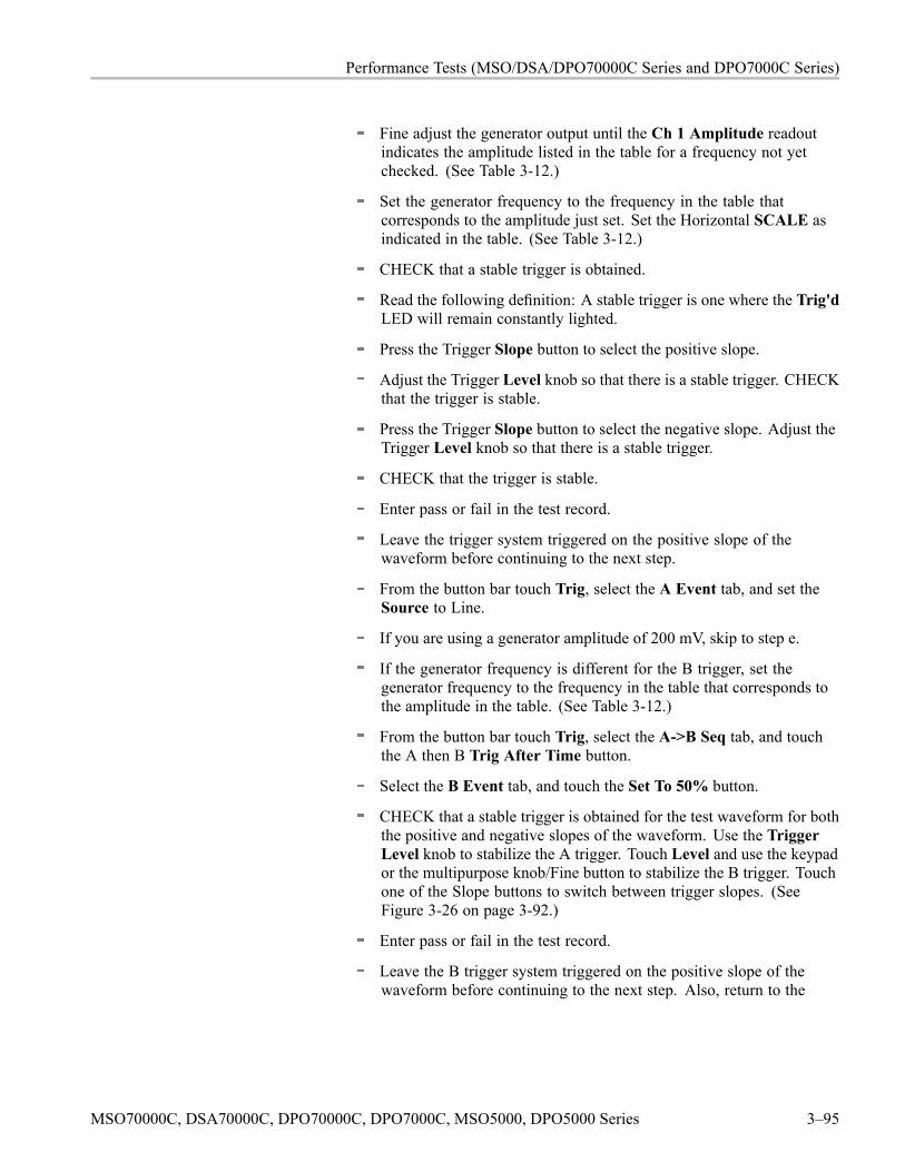
Performance Tests (MSO/DSA/DPO70000C Series and DPO7000C Series)
Fine adjust the generator output until the Ch 1 Amplitude readoutindicates the amplitude listed in the table for a frequency not yetchecked. (See Table 3-12.)
Set the generator frequency to the frequency in the table thatcorresponds to the amplitude just set. Set the Horizontal SCALE asindicated in the table. (See Table 3-12.)
CHECK that a stable trigger is obtained.
Read the following definition: A stable trigger is one where the Trig'dLED will remain constantly lighted.
Press the Trigger Slope button to select the positive slope.
Adjust the Trigger Level knob so that there is a stable trigger. CHECKthat the trigger is stable.
Press the Trigger Slope button to select the negative slope. Adjust theTrigger Level knob so that there is a stable trigger.
CHECK that the trigger is stable.
Enter pass or fail in the test record.
Leave the trigger system triggered on the positive slope of thewaveform before continuing to the next step.
From the button bar touch Trig, select the A Event tab, and set theSource to Line.
If you are using a generator amplitude of 200 mV, skip to step e.
If the generator frequency is different for the B trigger, set thegenerator frequency to the frequency in the table that corresponds tothe amplitude in the table. (See Table 3-12.)
From the button bar touch Trig, select the A->B Seq tab, and touchthe A then B Trig After Time button.
Select the B Event tab, and touch the Set To 50% button.
CHECK that a stable trigger is obtained for the test waveform for boththe positive and negative slopes of the waveform. Use the TriggerLevel knob to stabilize the A trigger. Touch Level and use the keypador the multipurpose knob/Fine button to stabilize the B trigger. Touchone of the Slope buttons to switch between trigger slopes. (SeeFigure 3-26 on page 3-92.)
Enter pass or fail in the test record.
Leave the B trigger system triggered on the positive slope of thewaveform before continuing to the next step. Also, return to the
MSO70000C, DSA70000C, DPO70000C, DPO7000C, MSO5000, DPO5000 Series 3–95
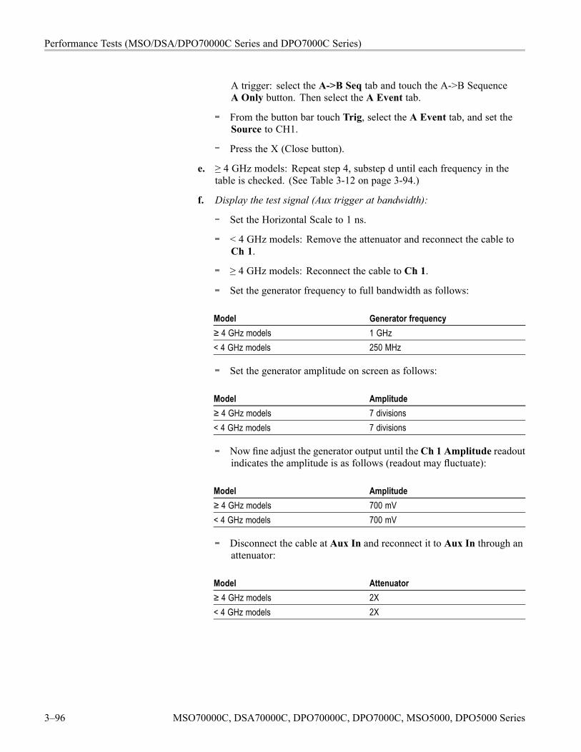
Performance Tests (MSO/DSA/DPO70000C Series and DPO7000C Series)
A trigger: select the A->B Seq tab and touch the A->B SequenceA Only button. Then select the A Event tab.
From the button bar touch Trig, select the A Event tab, and set theSource to CH1.
Press the X (Close button).
e. ≥ 4 GHz models: Repeat step 4, substep d until each frequency in thetable is checked. (See Table 3-12 on page 3-94.)
f. Display the test signal (Aux trigger at bandwidth):
Set the Horizontal Scale to 1 ns.
< 4 GHz models: Remove the attenuator and reconnect the cable toCh 1.
≥ 4 GHz models: Reconnect the cable to Ch 1.
Set the generator frequency to full bandwidth as follows:
Model Generator frequency≥ 4 GHz models 1 GHz< 4 GHz models 250 MHz
Set the generator amplitude on screen as follows:
Model Amplitude≥ 4 GHz models 7 divisions< 4 GHz models 7 divisions
Now fine adjust the generator output until the Ch 1 Amplitude readoutindicates the amplitude is as follows (readout may fluctuate):
Model Amplitude≥ 4 GHz models 700 mV< 4 GHz models 700 mV
Disconnect the cable at Aux In and reconnect it to Aux In through anattenuator:
Model Attenuator≥ 4 GHz models 2X< 4 GHz models 2X
3–96 MSO70000C, DSA70000C, DPO70000C, DPO7000C, MSO5000, DPO5000 Series
Performance Tests (MSO/DSA/DPO70000C Series and DPO7000C Series)
g. Repeat step 3, substep f only, for the full bandwidth selected.
NOTE. You just checked the trigger sensitivity. If desired, you may repeatsteps 1 through step 4 substep c for the other channels (Ch 2, Ch 3, and Ch 4).
5. Disconnect the hookup: Disconnect the equipment from Aux In and thechannel last tested.
Output Signal ChecksThe procedure that follows checks those characteristics of the output signals thatare listed as checked under Warranted Characteristics in Specifications.
Check Aux Trigger Out Equipment required PrerequisitesOne precision 50 Ω coaxial cable (Item 4) (See page 3-18, Prerequisites.) Also, the
instrument must have passed Check DCVoltage Measurement Accuracy. (Seepage 3-42, Check DC Voltage MeasurementAccuracy.)
1. Install the test hookup and preset the instrument controls:
Figure 3-27: Initial test hookup
a. Hook up test-signal source: Connect Aux Out to Ch 2 through a 50 Ωprecision cable and an adapter. (See Figure 3-27.)
b. Initialize the instrument: Press the Default Setup button.
MSO70000C, DSA70000C, DPO70000C, DPO7000C, MSO5000, DPO5000 Series 3–97

Performance Tests (MSO/DSA/DPO70000C Series and DPO7000C Series)
c. Modify the initialized front-panel control settings:
Press the Vertical Ch 1 button to toggle it off.
Set the Horizontal Scale to 200 μs.
From the button bar, touch Horiz/Acq and select the Acquisition tab.
Touch Average and set the number of averages to 64.
Touch the X (close) button.
2. Confirm Aux Out is within limits for logic levels:
a. Display the test signal:
Press the Vertical Ch 2 button to display that channel.
< 4 GHz models: Touch Vertical, select Vertical Setup, and thentouch Termination 50 Ω.
Set the Vertical Scale to 500 mV.
Use the Vertical Position knob to center the display on screen.
b. Measure logic levels:
From the button bar, touchMeasure and select the Ampl tab.
Touch the High and Low buttons.
Touch the X (close) button.
c. Check Aux Out output against limits: CHECK that the Ch 2 High readoutis ≥1.0 volt and that the Ch 2 Low readout ≤0.25 volts. (See Figure 3-28.)
3. Disconnect the hookup: Disconnect the test setup from the inputs and outputs.
Figure 3-28: Measurement of trigger out limits
3–98 MSO70000C, DSA70000C, DPO70000C, DPO7000C, MSO5000, DPO5000 Series
Performance Tests (MSO/DSA/DPO70000C Series and DPO7000C Series)
Check ProbeCompensation or Fast
Edge Output
Equipment required PrerequisitesOne BNC to Minigrabber adapter (item 18)One precision 50 Ω coaxial cable (Item 21)One DC calibration generator (Item 6)One adapter (Item 19)
(See page 3-18, Prerequisites.) Also,the instrument must have passed CheckTimebase and Delay Time Accuracy andReference. (See page 3-72.)
1. Install the test hookup and preset the instrument controls:
a. Hook up test-signal: Refer to the following figure.
Figure 3-29: Initial test hookup
b. Initialize the instrument: Press the Default Setup button.
c. Modify the initialized front-panel control settings:
Set the Vertical Scale to 200 mV.
Set the Horizontal Scale to 200 μs.
Press Push-Set 50%.
Use the Vertical Position knob to center the display on screen.
From the button bar, touch Horiz/Acq and select the Acquisition tab.
Touch Average and set the number of averages to 128.
MSO70000C, DSA70000C, DPO70000C, DPO7000C, MSO5000, DPO5000 Series 3–99
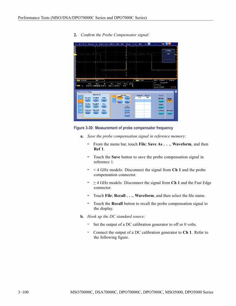
Performance Tests (MSO/DSA/DPO70000C Series and DPO7000C Series)
2. Confirm the Probe Compensator signal:
Figure 3-30: Measurement of probe compensator frequency
a. Save the probe compensation signal in reference memory:
From the menu bar, touch File; Save As . . .,Waveform, and thenRef 1.
Touch the Save button to save the probe compensation signal inreference 1.
< 4 GHz models: Disconnect the signal from Ch 1 and the probecompensation connector.
≥ 4 GHz models: Disconnect the signal from Ch 1 and the Fast Edgeconnector.
Touch File; Recall . . .,Waveform, and then select the file name.
Touch the Recall button to recall the probe compensation signal tothe display.
b. Hook up the DC standard source:
Set the output of a DC calibration generator to off or 0 volts.
Connect the output of a DC calibration generator to Ch 1. Refer tothe following figure.
3–100 MSO70000C, DSA70000C, DPO70000C, DPO7000C, MSO5000, DPO5000 Series
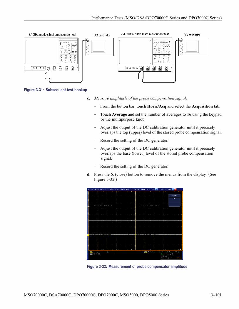
Performance Tests (MSO/DSA/DPO70000C Series and DPO7000C Series)
Figure 3-31: Subsequent test hookup
c. Measure amplitude of the probe compensation signal:
From the button bar, touch Horiz/Acq and select the Acquisition tab.
Touch Average and set the number of averages to 16 using the keypador the multipurpose knob.
Adjust the output of the DC calibration generator until it preciselyoverlaps the top (upper) level of the stored probe compensation signal.
Record the setting of the DC generator.
Adjust the output of the DC calibration generator until it preciselyoverlaps the base (lower) level of the stored probe compensationsignal.
Record the setting of the DC generator.
d. Press the X (close) button to remove the menus from the display. (SeeFigure 3-32.)
Figure 3-32: Measurement of probe compensator amplitude
MSO70000C, DSA70000C, DPO70000C, DPO7000C, MSO5000, DPO5000 Series 3–101
Performance Tests (MSO/DSA/DPO70000C Series and DPO7000C Series)
e. Check against limits:
Subtract the value just obtained (base level) from that obtainedpreviously (top level).
CHECK that the difference obtained is within limits as follows:
Model Limits≥ 4 GHz models 343.2 mV to 536.8 mV< 4 GHz models 985 mV to 1015 mV
Enter voltage difference on test record.
3. Disconnect the hookup: Disconnect the equipment from Ch 1.
3–102 MSO70000C, DSA70000C, DPO70000C, DPO7000C, MSO5000, DPO5000 Series
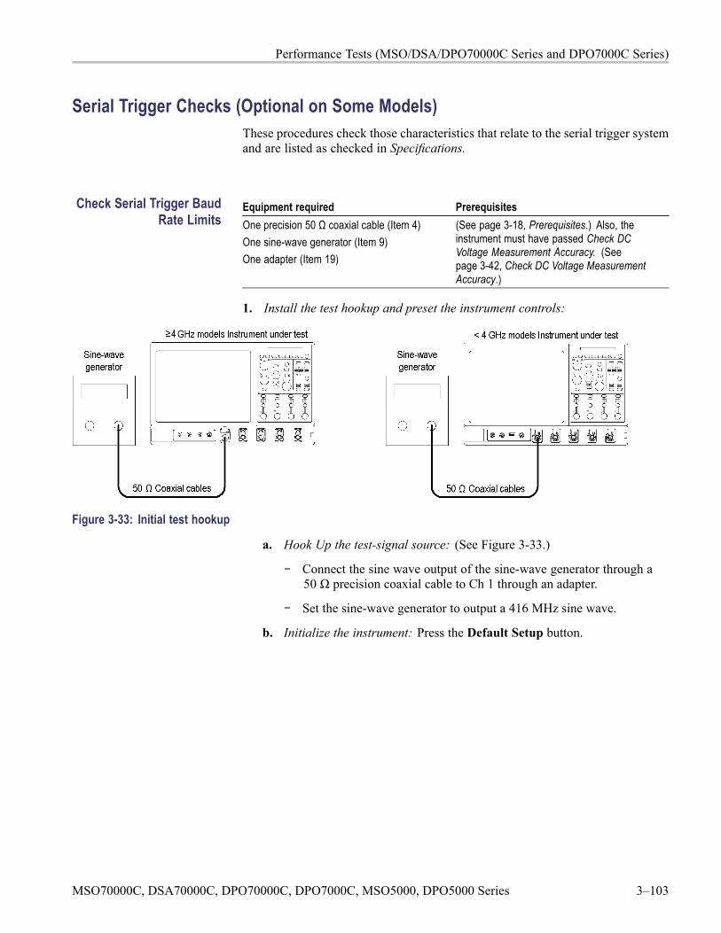
Performance Tests (MSO/DSA/DPO70000C Series and DPO7000C Series)
Serial Trigger Checks (Optional on Some Models)These procedures check those characteristics that relate to the serial trigger systemand are listed as checked in Specifications.
Check Serial Trigger BaudRate Limits
Equipment required PrerequisitesOne precision 50 Ω coaxial cable (Item 4)One sine-wave generator (Item 9)One adapter (Item 19)
(See page 3-18, Prerequisites.) Also, theinstrument must have passed Check DCVoltage Measurement Accuracy. (Seepage 3-42, Check DC Voltage MeasurementAccuracy.)
1. Install the test hookup and preset the instrument controls:
Figure 3-33: Initial test hookup
a. Hook Up the test-signal source: (See Figure 3-33.)
Connect the sine wave output of the sine-wave generator through a50 Ω precision coaxial cable to Ch 1 through an adapter.
Set the sine-wave generator to output a 416 MHz sine wave.
b. Initialize the instrument: Press the Default Setup button.
MSO70000C, DSA70000C, DPO70000C, DPO7000C, MSO5000, DPO5000 Series 3–103
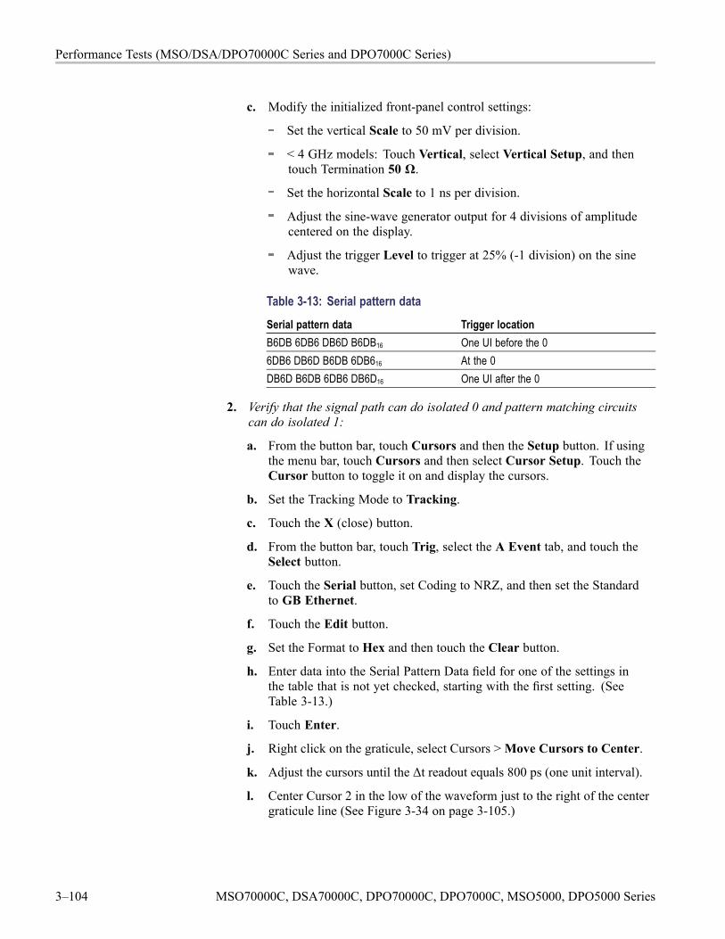
Performance Tests (MSO/DSA/DPO70000C Series and DPO7000C Series)
c. Modify the initialized front-panel control settings:
Set the vertical Scale to 50 mV per division.
< 4 GHz models: Touch Vertical, select Vertical Setup, and thentouch Termination 50 Ω.
Set the horizontal Scale to 1 ns per division.
Adjust the sine-wave generator output for 4 divisions of amplitudecentered on the display.
Adjust the trigger Level to trigger at 25% (-1 division) on the sinewave.
Table 3-13: Serial pattern dataSerial pattern data Trigger locationB6DB 6DB6 DB6D B6DB16 One UI before the 06DB6 DB6D B6DB 6DB616 At the 0DB6D B6DB 6DB6 DB6D16 One UI after the 0
2. Verify that the signal path can do isolated 0 and pattern matching circuitscan do isolated 1:
a. From the button bar, touch Cursors and then the Setup button. If usingthe menu bar, touch Cursors and then select Cursor Setup. Touch theCursor button to toggle it on and display the cursors.
b. Set the Tracking Mode to Tracking.
c. Touch the X (close) button.
d. From the button bar, touch Trig, select the A Event tab, and touch theSelect button.
e. Touch the Serial button, set Coding to NRZ, and then set the Standardto GB Ethernet.
f. Touch the Edit button.
g. Set the Format to Hex and then touch the Clear button.
h. Enter data into the Serial Pattern Data field for one of the settings inthe table that is not yet checked, starting with the first setting. (SeeTable 3-13.)
i. Touch Enter.
j. Right click on the graticule, select Cursors >Move Cursors to Center.
k. Adjust the cursors until the Δt readout equals 800 ps (one unit interval).
l. Center Cursor 2 in the low of the waveform just to the right of the centergraticule line (See Figure 3-34 on page 3-105.)
3–104 MSO70000C, DSA70000C, DPO70000C, DPO7000C, MSO5000, DPO5000 Series
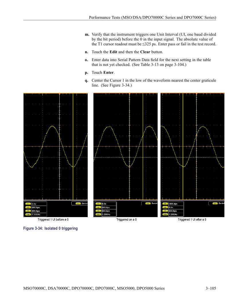
Performance Tests (MSO/DSA/DPO70000C Series and DPO7000C Series)
m. Verify that the instrument triggers one Unit Interval (UI, one baud dividedby the bit period) before the 0 in the input signal. The absolute value ofthe T1 cursor readout must be ≤325 ps. Enter pass or fail in the test record.
n. Touch the Edit and then the Clear button.
o. Enter data into Serial Pattern Data field for the next setting in the tablethat is not yet checked. (See Table 3-13 on page 3-104.)
p. Touch Enter.
q. Center the Cursor 1 in the low of the waveform nearest the center graticuleline. (See Figure 3-34.)
Figure 3-34: Isolated 0 triggering
MSO70000C, DSA70000C, DPO70000C, DPO7000C, MSO5000, DPO5000 Series 3–105
Performance Tests (MSO/DSA/DPO70000C Series and DPO7000C Series)
r. Verify that the instrument triggers at the 0 in the input signal. The absolutevalue of the T1 cursor readout must be ≤325 ps. Enter pass or fail in thetest record.
s. Touch the Edit and then the Clear button.
t. Enter data into Serial Pattern Data field for the next setting in the tablethat is not yet checked. (See Table 3-13 on page 3-104.)
u. Touch Enter.
v. Center Cursor 1 in the low of the waveform just to the left of the centergraticule line. (See Figure 3-34 on page 3-105.)
w. Verify that the instrument triggers one Unit Interval (UI) after the 0 in theinput signal. The absolute value of the T2 cursor readout must be ≤325 ps.Enter pass or fail in the test record.
3. Verify that the serial path and pattern matching circuits can do isolated 1s:
a. Adjust the trigger Level to trigger at 75% (+1 division) on the sine wave.
b. Touch the Edit and then the Clear button.
c. Enter data into the Serial Pattern Data field for one of the settings inthe table that is not yet checked, starting with the first setting. (SeeTable 3-14.)
Table 3-14: Word recognizer dataSerial pattern data Trigger location4924 9249 2492 492416 One UI before the 19249 2492 4924 924916 At the 12492 4924 9249 249216 One UI after the 1
e. Touch Enter.
f. Center Cursor 2 in the high of the waveform just to the right of the centergraticule line. (See Figure 3-35 on page 3-107.)
g. Verify that the instrument triggers one Unit Interval (UI) before the 1 inthe input signal. The absolute value of the T1 cursor readout must be≤325 ps. Enter pass or fail in the test record.
h. Touch the Edit and then the Clear button.
i. Enter data into the Serial Pattern Data field for the next setting that isnot yet checked.
j. Touch Enter.
k. Center the Cursor 1 in the waveform high nearest the center graticule line.(See Figure 3-35 on page 3-107.)
3–106 MSO70000C, DSA70000C, DPO70000C, DPO7000C, MSO5000, DPO5000 Series
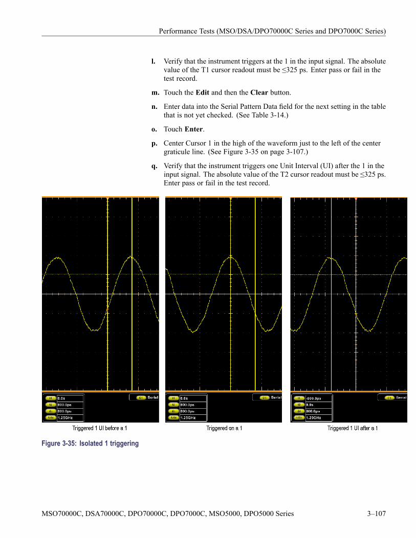
Performance Tests (MSO/DSA/DPO70000C Series and DPO7000C Series)
l. Verify that the instrument triggers at the 1 in the input signal. The absolutevalue of the T1 cursor readout must be ≤325 ps. Enter pass or fail in thetest record.
m. Touch the Edit and then the Clear button.
n. Enter data into the Serial Pattern Data field for the next setting in the tablethat is not yet checked. (See Table 3-14.)
o. Touch Enter.
p. Center Cursor 1 in the high of the waveform just to the left of the centergraticule line. (See Figure 3-35 on page 3-107.)
q. Verify that the instrument triggers one Unit Interval (UI) after the 1 in theinput signal. The absolute value of the T2 cursor readout must be ≤325 ps.Enter pass or fail in the test record.
Figure 3-35: Isolated 1 triggering
MSO70000C, DSA70000C, DPO70000C, DPO7000C, MSO5000, DPO5000 Series 3–107
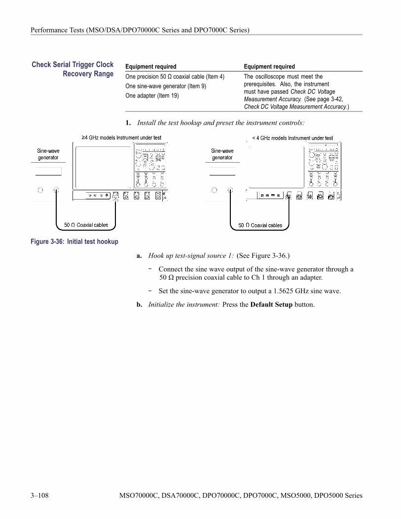
Performance Tests (MSO/DSA/DPO70000C Series and DPO7000C Series)
Check Serial Trigger ClockRecovery Range
Equipment required Equipment requiredOne precision 50 Ω coaxial cable (Item 4)One sine-wave generator (Item 9)One adapter (Item 19)
The oscilloscope must meet theprerequisites. Also, the instrumentmust have passed Check DC VoltageMeasurement Accuracy. (See page 3-42,Check DC Voltage Measurement Accuracy.)
1. Install the test hookup and preset the instrument controls:
Figure 3-36: Initial test hookup
a. Hook up test-signal source 1: (See Figure 3-36.)
Connect the sine wave output of the sine-wave generator through a50 Ω precision coaxial cable to Ch 1 through an adapter.
Set the sine-wave generator to output a 1.5625 GHz sine wave.
b. Initialize the instrument: Press the Default Setup button.
3–108 MSO70000C, DSA70000C, DPO70000C, DPO7000C, MSO5000, DPO5000 Series
Performance Tests (MSO/DSA/DPO70000C Series and DPO7000C Series)
c. Modify the initialized front-panel control settings:
Set the Vertical Scale to 50 mV per division.
< 4 GHz models: Touch Vertical, select Vertical Setup, and thentouch Termination 50 Ω.
Set the horizontal Scale to 200 ps per division.
From the button bar, touch the Display button.
Set the Display Style to Dots.
Set the Display Persistence to Variable, and set the persist Time to3.0 s.
Touch the X (close) button.
Adjust the sine-wave generator output for 8 divisions of amplitude.
From the button bar, touch Trig and select the A Event tab.
Touch the Select button.
Touch the Comm button. Set Source to Ch1, Type to R Clk, andCoding to NRZ.
2. Verify the clock recovery at frequency:
a. From the button bar, touch Trig and select the A Event tab.
b. Set the sine-wave generator to output one of the input frequencies in thetable that is not yet checked, starting with the first setting. (See Table 3-15on page 3-110.)
c. Set the instrument Bit Rate to the Recovered clock Baud rate listed in thetable for the current input frequency.
NOTE. The instrument will attempt to acquire lock once. If the input data isdisrupted, removed, or heavily distorted, the instrument may not acquire lockor may lose lock. If the recovered clock is not locked to the incoming data, thewaveform display will not be stable. Once the input data is available, pressthe PUSH SET TO 50% knob to force the instrument to acquire lock again.
d. Press PUSH-SET 50%.
MSO70000C, DSA70000C, DPO70000C, DPO7000C, MSO5000, DPO5000 Series 3–109
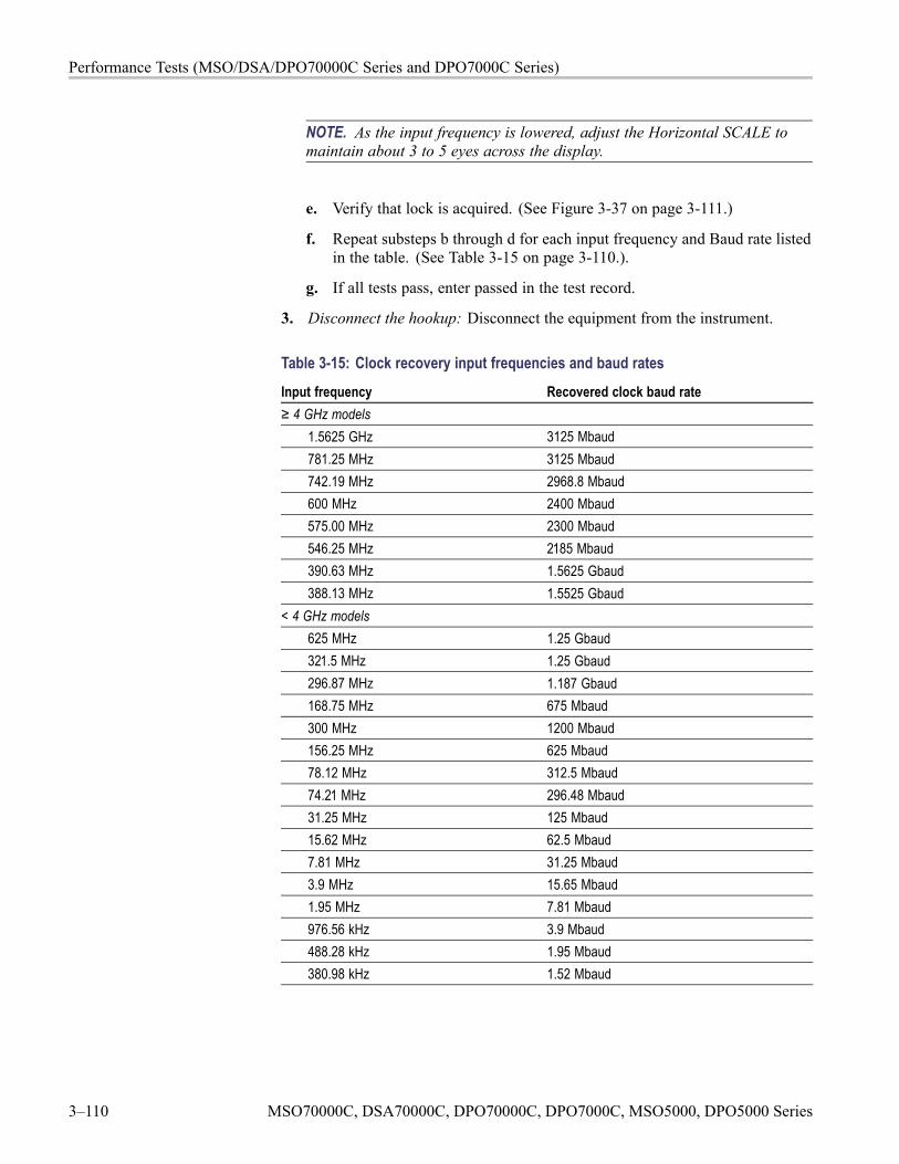
Performance Tests (MSO/DSA/DPO70000C Series and DPO7000C Series)
NOTE. As the input frequency is lowered, adjust the Horizontal SCALE tomaintain about 3 to 5 eyes across the display.
e. Verify that lock is acquired. (See Figure 3-37 on page 3-111.)
f. Repeat substeps b through d for each input frequency and Baud rate listedin the table. (See Table 3-15 on page 3-110.).
g. If all tests pass, enter passed in the test record.
3. Disconnect the hookup: Disconnect the equipment from the instrument.
Table 3-15: Clock recovery input frequencies and baud ratesInput frequency Recovered clock baud rate≥ 4 GHz models
1.5625 GHz 3125 Mbaud781.25 MHz 3125 Mbaud742.19 MHz 2968.8 Mbaud600 MHz 2400 Mbaud575.00 MHz 2300 Mbaud546.25 MHz 2185 Mbaud390.63 MHz 1.5625 Gbaud388.13 MHz 1.5525 Gbaud
< 4 GHz models625 MHz 1.25 Gbaud321.5 MHz 1.25 Gbaud296.87 MHz 1.187 Gbaud168.75 MHz 675 Mbaud300 MHz 1200 Mbaud156.25 MHz 625 Mbaud78.12 MHz 312.5 Mbaud74.21 MHz 296.48 Mbaud31.25 MHz 125 Mbaud15.62 MHz 62.5 Mbaud7.81 MHz 31.25 Mbaud3.9 MHz 15.65 Mbaud1.95 MHz 7.81 Mbaud976.56 kHz 3.9 Mbaud488.28 kHz 1.95 Mbaud380.98 kHz 1.52 Mbaud
3–110 MSO70000C, DSA70000C, DPO70000C, DPO7000C, MSO5000, DPO5000 Series
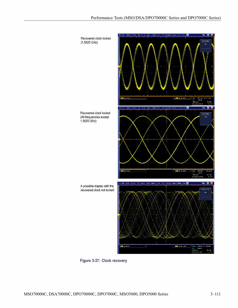
Performance Tests (MSO/DSA/DPO70000C Series and DPO7000C Series)
Figure 3-37: Clock recovery
MSO70000C, DSA70000C, DPO70000C, DPO7000C, MSO5000, DPO5000 Series 3–111
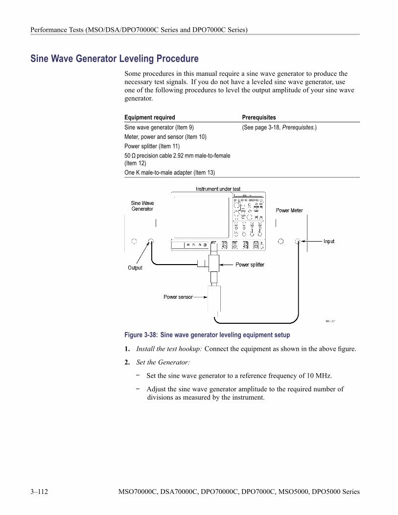
Performance Tests (MSO/DSA/DPO70000C Series and DPO7000C Series)
Sine Wave Generator Leveling ProcedureSome procedures in this manual require a sine wave generator to produce thenecessary test signals. If you do not have a leveled sine wave generator, useone of the following procedures to level the output amplitude of your sine wavegenerator.
Equipment required PrerequisitesSine wave generator (Item 9)Meter, power and sensor (Item 10)Power splitter (Item 11)50 Ω precision cable 2.92 mm male-to-female(Item 12)One K male-to-male adapter (Item 13)
(See page 3-18, Prerequisites.)
Figure 3-38: Sine wave generator leveling equipment setup
1. Install the test hookup: Connect the equipment as shown in the above figure.
2. Set the Generator:
Set the sine wave generator to a reference frequency of 10 MHz.
Adjust the sine wave generator amplitude to the required number ofdivisions as measured by the instrument.
3–112 MSO70000C, DSA70000C, DPO70000C, DPO7000C, MSO5000, DPO5000 Series
Performance Tests (MSO/DSA/DPO70000C Series and DPO7000C Series)
3. Record the reference level: Note the reading on the level meter.
4. Set the generator to the new frequency and reference level:
Change the sine wave generator to the desired new frequency.
Input the correction factor and/or the new frequency into the level meter.
Adjust the sine wave generator amplitude until the level meter again readsthe value noted in step 3. The signal amplitude is now correctly set forthe new frequency.
Equipment required PrerequisitesSine wave generator (Item 9)Level meter and power sensor (Item 10)Two male N to female BNC adapters (Item14)Two precision coaxial cables (Item 4)One or two SMA male-to-female BNCadapters (Item 19)
(See page 3-18, Prerequisites.)
1. Install the test hookup: Connect the equipment as shown in the figure below(start with the sine wave generator connected to the instrument). (SeeFigure 3-39.)
2. Set the Generator:
Set the sine wave generator to a reference frequency of 10 MHz.
Adjust the sine wave generator amplitude to the required number ofdivisions as measured by the instrument.
MSO70000C, DSA70000C, DPO70000C, DPO7000C, MSO5000, DPO5000 Series 3–113
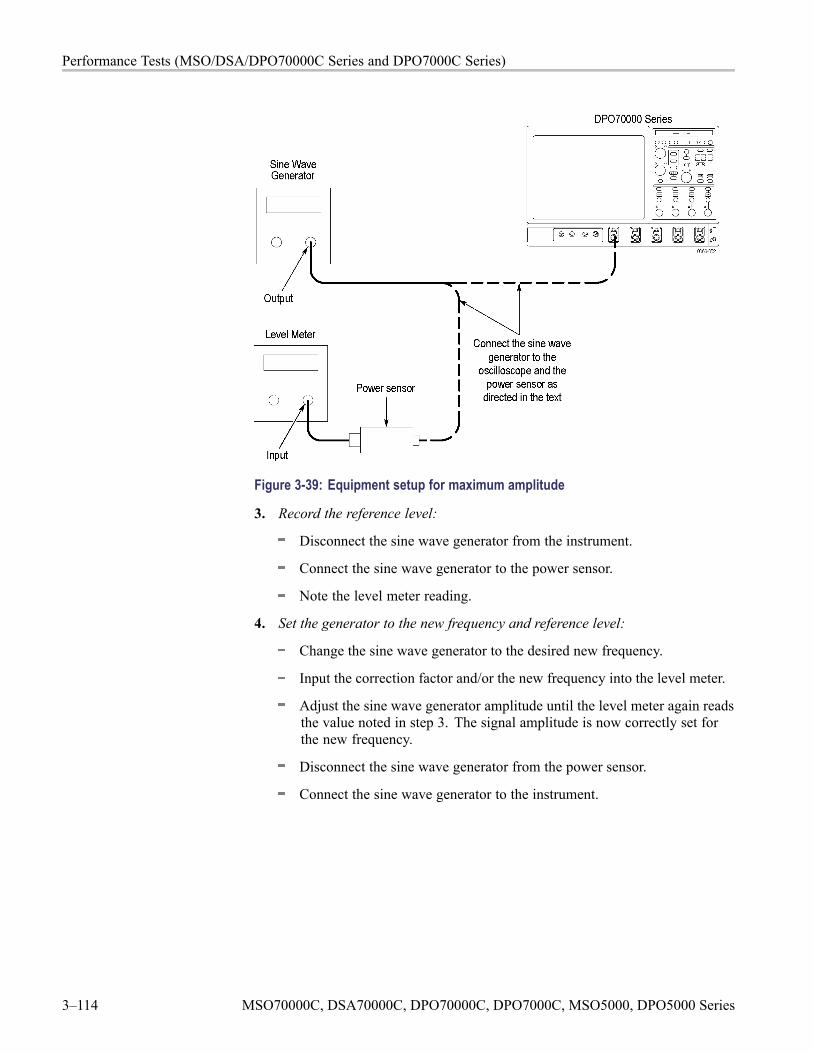
Performance Tests (MSO/DSA/DPO70000C Series and DPO7000C Series)
Figure 3-39: Equipment setup for maximum amplitude
3. Record the reference level:
Disconnect the sine wave generator from the instrument.
Connect the sine wave generator to the power sensor.
Note the level meter reading.
4. Set the generator to the new frequency and reference level:
Change the sine wave generator to the desired new frequency.
Input the correction factor and/or the new frequency into the level meter.
Adjust the sine wave generator amplitude until the level meter again readsthe value noted in step 3. The signal amplitude is now correctly set forthe new frequency.
Disconnect the sine wave generator from the power sensor.
Connect the sine wave generator to the instrument.
3–114 MSO70000C, DSA70000C, DPO70000C, DPO7000C, MSO5000, DPO5000 Series

Performance Verification (MSO/DPO5000Series)

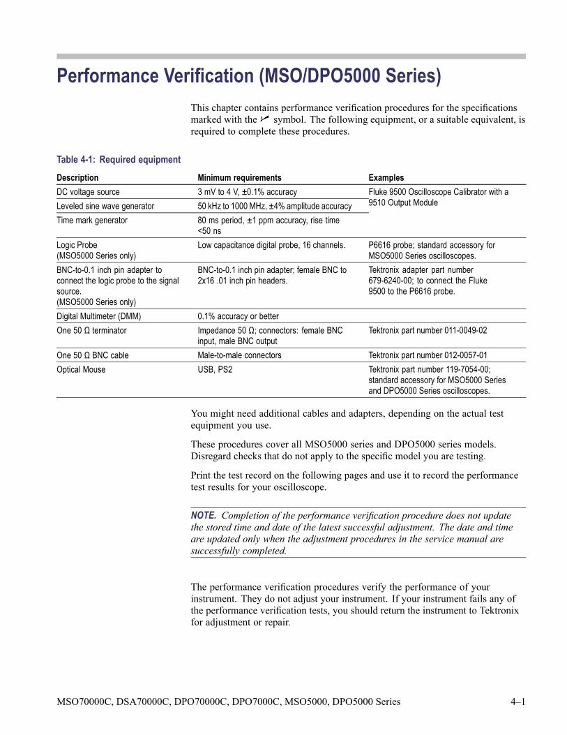
Performance Verification (MSO/DPO5000 Series)This chapter contains performance verification procedures for the specificationsmarked with the symbol. The following equipment, or a suitable equivalent, isrequired to complete these procedures.
Table 4-1: Required equipmentDescription Minimum requirements ExamplesDC voltage source 3 mV to 4 V, ±0.1% accuracyLeveled sine wave generator 50 kHz to 1000 MHz, ±4% amplitude accuracyTime mark generator 80 ms period, ±1 ppm accuracy, rise time
<50 ns
Fluke 9500 Oscilloscope Calibrator with a9510 Output Module
Logic Probe(MSO5000 Series only)
Low capacitance digital probe, 16 channels. P6616 probe; standard accessory forMSO5000 Series oscilloscopes.
BNC-to-0.1 inch pin adapter toconnect the logic probe to the signalsource.(MSO5000 Series only)
BNC-to-0.1 inch pin adapter; female BNC to2x16 .01 inch pin headers.
Tektronix adapter part number679-6240-00; to connect the Fluke9500 to the P6616 probe.
Digital Multimeter (DMM) 0.1% accuracy or betterOne 50 Ω terminator Impedance 50 Ω; connectors: female BNC
input, male BNC outputTektronix part number 011-0049-02
One 50 Ω BNC cable Male-to-male connectors Tektronix part number 012-0057-01Optical Mouse USB, PS2 Tektronix part number 119-7054-00;
standard accessory for MSO5000 Seriesand DPO5000 Series oscilloscopes.
You might need additional cables and adapters, depending on the actual testequipment you use.
These procedures cover all MSO5000 series and DPO5000 series models.Disregard checks that do not apply to the specific model you are testing.
Print the test record on the following pages and use it to record the performancetest results for your oscilloscope.
NOTE. Completion of the performance verification procedure does not updatethe stored time and date of the latest successful adjustment. The date and timeare updated only when the adjustment procedures in the service manual aresuccessfully completed.
The performance verification procedures verify the performance of yourinstrument. They do not adjust your instrument. If your instrument fails any ofthe performance verification tests, you should return the instrument to Tektronixfor adjustment or repair.
MSO70000C, DSA70000C, DPO70000C, DPO7000C, MSO5000, DPO5000 Series 4–1
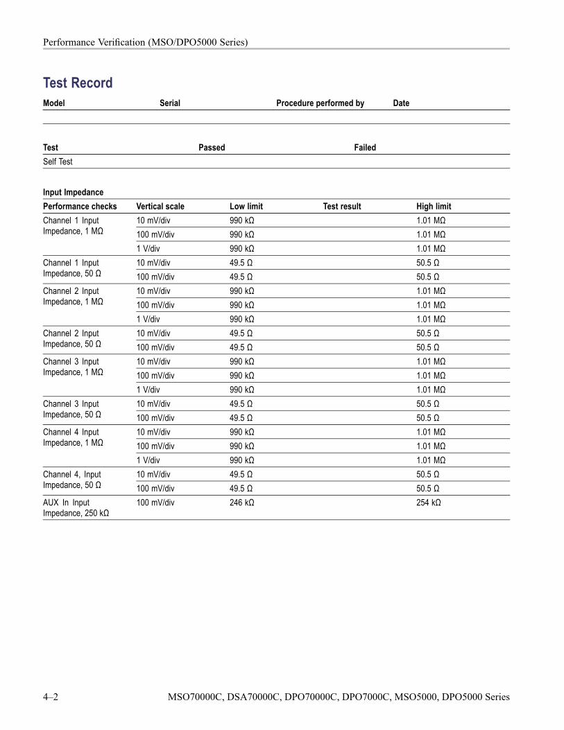
Performance Verification (MSO/DPO5000 Series)
Test RecordModel Serial Procedure performed by Date
Test Passed FailedSelf Test
Input ImpedancePerformance checks Vertical scale Low limit Test result High limit
10 mV/div 990 kΩ 1.01 MΩ100 mV/div 990 kΩ 1.01 MΩ
Channel 1 InputImpedance, 1 MΩ
1 V/div 990 kΩ 1.01 MΩ10 mV/div 49.5 Ω 50.5 ΩChannel 1 Input
Impedance, 50 Ω 100 mV/div 49.5 Ω 50.5 Ω10 mV/div 990 kΩ 1.01 MΩ100 mV/div 990 kΩ 1.01 MΩ
Channel 2 InputImpedance, 1 MΩ
1 V/div 990 kΩ 1.01 MΩ10 mV/div 49.5 Ω 50.5 ΩChannel 2 Input
Impedance, 50 Ω 100 mV/div 49.5 Ω 50.5 Ω10 mV/div 990 kΩ 1.01 MΩ100 mV/div 990 kΩ 1.01 MΩ
Channel 3 InputImpedance, 1 MΩ
1 V/div 990 kΩ 1.01 MΩ10 mV/div 49.5 Ω 50.5 ΩChannel 3 Input
Impedance, 50 Ω 100 mV/div 49.5 Ω 50.5 Ω10 mV/div 990 kΩ 1.01 MΩ100 mV/div 990 kΩ 1.01 MΩ
Channel 4 InputImpedance, 1 MΩ
1 V/div 990 kΩ 1.01 MΩ10 mV/div 49.5 Ω 50.5 ΩChannel 4, Input
Impedance, 50 Ω 100 mV/div 49.5 Ω 50.5 ΩAUX In InputImpedance, 250 kΩ
100 mV/div 246 kΩ 254 kΩ
4–2 MSO70000C, DSA70000C, DPO70000C, DPO7000C, MSO5000, DPO5000 Series

Performance Verification (MSO/DPO5000 Series)
DC BalancePerformance checks Vertical scale Low limit Test result High limit
1 mV/div -0.2 mV 0.2 mV2 mV/div -0.2 mV 0.2 mV10 mV/div -1 mV 1 mV100 mV/div -10 mV 10 mV
Channel 1 DC Balance,50 Ω, 20 MHz BW
1 V/div -100 mV 100 mV1 mV/div -0.2 mV 0.2 mV2 mV/div -0.4 mV 0.4 mV10 mV/div -2 mV 2 mV100 mV/div -20 mV 20 mV1 V/div -200 mV 200 mV
Channel 1 DC Balance,1 MΩ, 20 MHz BW
10 V/div -2 V 2 VChannel 1 DC Balance,50 Ω, 175 MHz BW
1 mV/div -0.2 mV 0.2 mV
Channel 1 DC Balance,1 MΩ, 175 MHz BW
1 mV/div -0.2 mV 0.2 mV
2 mV/div -0.2 mV 0.2 mV10 mV/div -1 mV 1 mV100 mV/div -10 mV 10 mV
Channel 1 DC Balance,50 Ω, 250 MHz BW
1 V/div -100 mV 100 mV2 mV/div -0.4 mV 0.4 mV10 mV/div -2 mV 2 mV100 mV/div -20 mV 20 mV1 V/div -200 mV 200 mV
Channel 1 DC Balance,1 MΩ, 250 MHz BW
10 V/div -2 V 2 V1 mV/div -0.2 mV 0.2 mV2 mV/div -0.2 mV 0.2 mV10 mV/div -1 mV 1 mV100 mV/div -10 mV 10 mV
Channel 1 DC Balance,50 Ω, Full BW
1 V/div -100 mV 100 mV1 mV/div -0.2 mV 0.2 mV2 mV/div -0.4 mV 0.4 mV10 mV/div -2 mV 2 mV100 mV/div -20 mV 20 mV1 V/div -200 mV 200 mV
Channel 1 DC Balance,1 MΩ, Full BW
10 V/div -2 V 2 V
MSO70000C, DSA70000C, DPO70000C, DPO7000C, MSO5000, DPO5000 Series 4–3

Performance Verification (MSO/DPO5000 Series)
DC BalancePerformance checks Vertical scale Low limit Test result High limit
1 mV/div -0.2 mV 0.2 mV2 mV/div -0.2 mV 0.2 mV10 mV/div -1 mV 1 mV100 mV/div -10 mV 10 mV
Channel 2 DC Balance,50 Ω, 20 MHz BW
1 V/div -100 mV 100 mV1 mV/div -0.2 mV 0.2 mV2 mV/div -0.4 mV 0.4 mV10 mV/div -2 mV 2 mV100 mV/div -20 mV 20 mV1 V/div -200 mV 200 mV
Channel 2 DC Balance,1 MΩ, 20 MHz BW
10 V/div -2 V 2 VChannel 2 DC Balance,50 Ω, 175 MHz BW
1 mV/div -0.2 mV 0.2 mV
Channel 2 DC Balance,1 MΩ, 175 MHz BW
1 mV/div -0.2 mV 0.2 mV
2 mV/div -0.2 mV 0.2 mV10 mV/div -1 mV 1 mV100 mV/div -10 mV 10 mV
Channel 2 DC Balance,50 Ω, 250 MHz BW
1 V/div -100 mV 100 mV2 mV/div -0.4 mV 0.4 mV10 mV/div -2 mV 2 mV100 mV/div -20 mV 20 mV1 V/div -200 mV 200 mV
Channel 2 DC Balance,1 MΩ, 250 MHz BW
10 V/div -2 V 2 V1 mV/div -0.2 mV 0.2 mV2 mV/div -0.2 mV 0.2 mV10 mV/div -1 mV 1 mV100 mV/div -10 mV 10 mV
Channel 2 DC Balance,50 Ω, Full BW
1 V/div -100 mV 100 mV1 mV/div -0.2 mV 0.2 mV2 mV/div -0.4 mV 0.4 mV10 mV/div -2 mV 2 mV100 mV/div -20 mV 20 mV1 V/div -200 mV 200 mV
Channel 2 DC Balance,1 MΩ, Full BW
10 V/div -2 V 2 V
4–4 MSO70000C, DSA70000C, DPO70000C, DPO7000C, MSO5000, DPO5000 Series
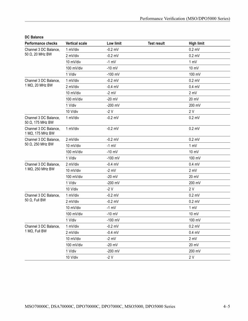
Performance Verification (MSO/DPO5000 Series)
DC BalancePerformance checks Vertical scale Low limit Test result High limit
1 mV/div -0.2 mV 0.2 mV2 mV/div -0.2 mV 0.2 mV10 mV/div -1 mV 1 mV100 mV/div -10 mV 10 mV
Channel 3 DC Balance,50 Ω, 20 MHz BW
1 V/div -100 mV 100 mV1 mV/div -0.2 mV 0.2 mV2 mV/div -0.4 mV 0.4 mV10 mV/div -2 mV 2 mV100 mV/div -20 mV 20 mV1 V/div -200 mV 200 mV
Channel 3 DC Balance,1 MΩ, 20 MHz BW
10 V/div -2 V 2 VChannel 3 DC Balance,50 Ω, 175 MHz BW
1 mV/div -0.2 mV 0.2 mV
Channel 3 DC Balance,1 MΩ, 175 MHz BW
1 mV/div -0.2 mV 0.2 mV
2 mV/div -0.2 mV 0.2 mV10 mV/div -1 mV 1 mV100 mV/div -10 mV 10 mV
Channel 3 DC Balance,50 Ω, 250 MHz BW
1 V/div -100 mV 100 mV2 mV/div -0.4 mV 0.4 mV10 mV/div -2 mV 2 mV100 mV/div -20 mV 20 mV1 V/div -200 mV 200 mV
Channel 3 DC Balance,1 MΩ, 250 MHz BW
10 V/div -2 V 2 V1 mV/div -0.2 mV 0.2 mV2 mV/div -0.2 mV 0.2 mV10 mV/div -1 mV 1 mV100 mV/div -10 mV 10 mV
Channel 3 DC Balance,50 Ω, Full BW
1 V/div -100 mV 100 mV1 mV/div -0.2 mV 0.2 mV2 mV/div -0.4 mV 0.4 mV10 mV/div -2 mV 2 mV100 mV/div -20 mV 20 mV1 V/div -200 mV 200 mV
Channel 3 DC Balance,1 MΩ, Full BW
10 V/div -2 V 2 V
MSO70000C, DSA70000C, DPO70000C, DPO7000C, MSO5000, DPO5000 Series 4–5
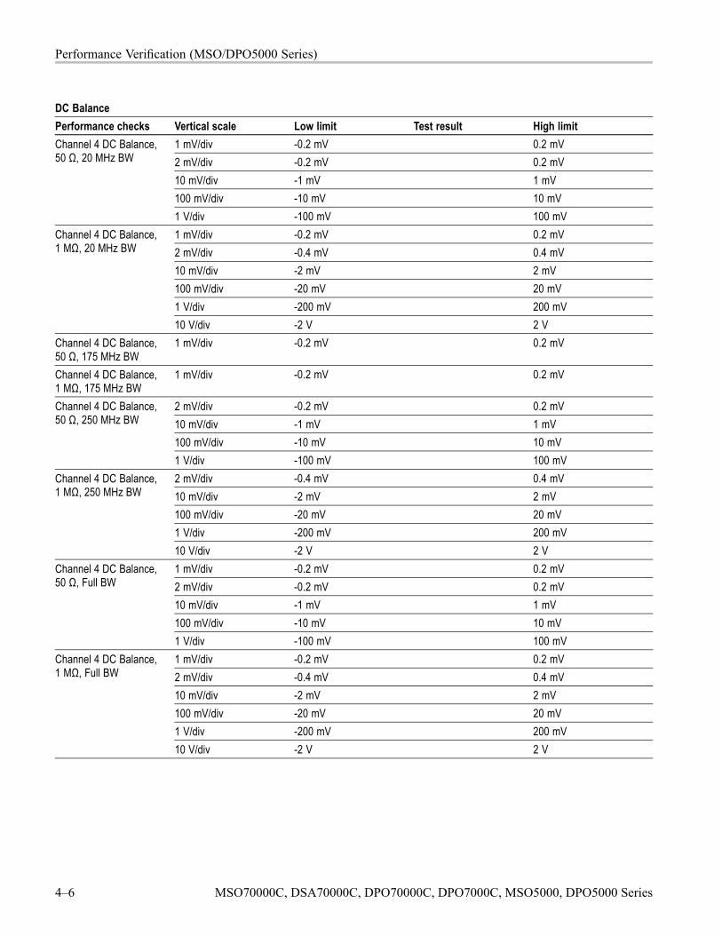
Performance Verification (MSO/DPO5000 Series)
DC BalancePerformance checks Vertical scale Low limit Test result High limit
1 mV/div -0.2 mV 0.2 mV2 mV/div -0.2 mV 0.2 mV10 mV/div -1 mV 1 mV100 mV/div -10 mV 10 mV
Channel 4 DC Balance,50 Ω, 20 MHz BW
1 V/div -100 mV 100 mV1 mV/div -0.2 mV 0.2 mV2 mV/div -0.4 mV 0.4 mV10 mV/div -2 mV 2 mV100 mV/div -20 mV 20 mV1 V/div -200 mV 200 mV
Channel 4 DC Balance,1 MΩ, 20 MHz BW
10 V/div -2 V 2 VChannel 4 DC Balance,50 Ω, 175 MHz BW
1 mV/div -0.2 mV 0.2 mV
Channel 4 DC Balance,1 MΩ, 175 MHz BW
1 mV/div -0.2 mV 0.2 mV
2 mV/div -0.2 mV 0.2 mV10 mV/div -1 mV 1 mV100 mV/div -10 mV 10 mV
Channel 4 DC Balance,50 Ω, 250 MHz BW
1 V/div -100 mV 100 mV2 mV/div -0.4 mV 0.4 mV10 mV/div -2 mV 2 mV100 mV/div -20 mV 20 mV1 V/div -200 mV 200 mV
Channel 4 DC Balance,1 MΩ, 250 MHz BW
10 V/div -2 V 2 V1 mV/div -0.2 mV 0.2 mV2 mV/div -0.2 mV 0.2 mV10 mV/div -1 mV 1 mV100 mV/div -10 mV 10 mV
Channel 4 DC Balance,50 Ω, Full BW
1 V/div -100 mV 100 mV1 mV/div -0.2 mV 0.2 mV2 mV/div -0.4 mV 0.4 mV10 mV/div -2 mV 2 mV100 mV/div -20 mV 20 mV1 V/div -200 mV 200 mV
Channel 4 DC Balance,1 MΩ, Full BW
10 V/div -2 V 2 V
4–6 MSO70000C, DSA70000C, DPO70000C, DPO7000C, MSO5000, DPO5000 Series
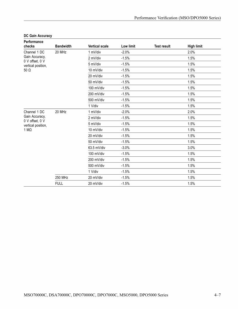
Performance Verification (MSO/DPO5000 Series)
DC Gain AccuracyPerformancechecks Bandwidth Vertical scale Low limit Test result High limit
1 mV/div -2.0% 2.0%2 mV/div -1.5% 1.5%5 mV/div -1.5% 1.5%10 mV/div -1.5% 1.5%20 mV/div -1.5% 1.5%50 mV/div -1.5% 1.5%100 mV/div -1.5% 1.5%200 mV/div -1.5% 1.5%500 mV/div -1.5% 1.5%
Channel 1 DCGain Accuracy,0 V offset, 0 Vvertical position,50 Ω
20 MHz
1 V/div -1.5% 1.5%1 mV/div -2.0% 2.0%2 mV/div -1.5% 1.5%5 mV/div -1.5% 1.5%10 mV/div -1.5% 1.5%20 mV/div -1.5% 1.5%50 mV/div -1.5% 1.5%63.5 mV/div -3.0% 3.0%100 mV/div -1.5% 1.5%200 mV/div -1.5% 1.5%500 mV/div -1.5% 1.5%
20 MHz
1 V/div -1.5% 1.5%250 MHz 20 mV/div -1.5% 1.5%
Channel 1 DCGain Accuracy,0 V offset, 0 Vvertical position,1 MΩ
FULL 20 mV/div -1.5% 1.5%
MSO70000C, DSA70000C, DPO70000C, DPO7000C, MSO5000, DPO5000 Series 4–7

Performance Verification (MSO/DPO5000 Series)
DC Gain AccuracyPerformancechecks Bandwidth Vertical scale Low limit Test result High limit
1 mV/div -2.0% 2.0%2 mV/div -1.5% 1.5%5 mV/div -1.5% 1.5%10 mV/div -1.5% 1.5%20 mV/div -1.5% 1.5%50 mV/div -1.5% 1.5%100 mV/div -1.5% 1.5%200 mV/div -1.5% 1.5%500 mV/div -1.5% 1.5%
Channel 2 DCGain Accuracy,0 V offset, 0 Vvertical position,50 Ω
20 MHz
1 V/div -1.5% 1.5%1 mV/div -2.0% 2.0%2 mV/div -1.5% 1.5%5 mV/div -1.5% 1.5%10 mV/div -1.5% 1.5%20 mV/div -1.5% 1.5%50 mV/div -1.5% 1.5%63.5 mV/div -3.0% 3.0%100 mV/div -1.5% 1.5%200 mV/div -1.5% 1.5%500 mV/div -1.5% 1.5%
20 MHz
1 V/div -1.5% 1.5%250 MHz 20 mV/div -1.5% 1.5%
Channel 2 DCGain Accuracy,0 V offset, 0 Vvertical position,1 MΩ
FULL 20 mV/div -1.5% 1.5%
4–8 MSO70000C, DSA70000C, DPO70000C, DPO7000C, MSO5000, DPO5000 Series

Performance Verification (MSO/DPO5000 Series)
DC Gain AccuracyPerformancechecks Bandwidth Vertical scale Low limit Test result High limit
1 mV/div -2.0% 2.0%2 mV/div -1.5% 1.5%5 mV/div -1.5% 1.5%10 mV/div -1.5% 1.5%20 mV/div -1.5% 1.5%50 mV/div -1.5% 1.5%100 mV/div -1.5% 1.5%200 mV/div -1.5% 1.5%500 mV/div -1.5% 1.5%
Channel 3 DCGain Accuracy,0 V offset, 0 Vvertical position,50 Ω
20 MHz
1 V/div -1.5% 1.5%1 mV/div -2.0% 2.0%2 mV/div -1.5% 1.5%5 mV/div -1.5% 1.5%10 mV/div -1.5% 1.5%20 mV/div -1.5% 1.5%50 mV/div -1.5% 1.5%63.5 mV/div -3.0% 3.0%100 mV/div -1.5% 1.5%200 mV/div -1.5% 1.5%500 mV/div -1.5% 1.5%
20 MHz
1 V/div -1.5% 1.5%250 MHz 20 mV/div -1.5% 1.5%
Channel 3 DCGain Accuracy,0 V offset, 0 Vvertical position,1 MΩ
FULL 20 mV/div -1.5% 1.5%
MSO70000C, DSA70000C, DPO70000C, DPO7000C, MSO5000, DPO5000 Series 4–9
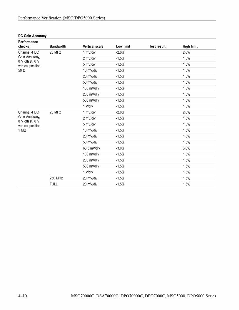
Performance Verification (MSO/DPO5000 Series)
DC Gain AccuracyPerformancechecks Bandwidth Vertical scale Low limit Test result High limit
1 mV/div -2.0% 2.0%2 mV/div -1.5% 1.5%5 mV/div -1.5% 1.5%10 mV/div -1.5% 1.5%20 mV/div -1.5% 1.5%50 mV/div -1.5% 1.5%100 mV/div -1.5% 1.5%200 mV/div -1.5% 1.5%500 mV/div -1.5% 1.5%
Channel 4 DCGain Accuracy,0 V offset, 0 Vvertical position,50 Ω
20 MHz
1 V/div -1.5% 1.5%1 mV/div -2.0% 2.0%2 mV/div -1.5% 1.5%5 mV/div -1.5% 1.5%10 mV/div -1.5% 1.5%20 mV/div -1.5% 1.5%50 mV/div -1.5% 1.5%63.5 mV/div -3.0% 3.0%100 mV/div -1.5% 1.5%200 mV/div -1.5% 1.5%500 mV/div -1.5% 1.5%
20 MHz
1 V/div -1.5% 1.5%250 MHz 20 mV/div -1.5% 1.5%
Channel 4 DCGain Accuracy,0 V offset, 0 Vvertical position,1 MΩ
FULL 20 mV/div -1.5% 1.5%
4–10 MSO70000C, DSA70000C, DPO70000C, DPO7000C, MSO5000, DPO5000 Series
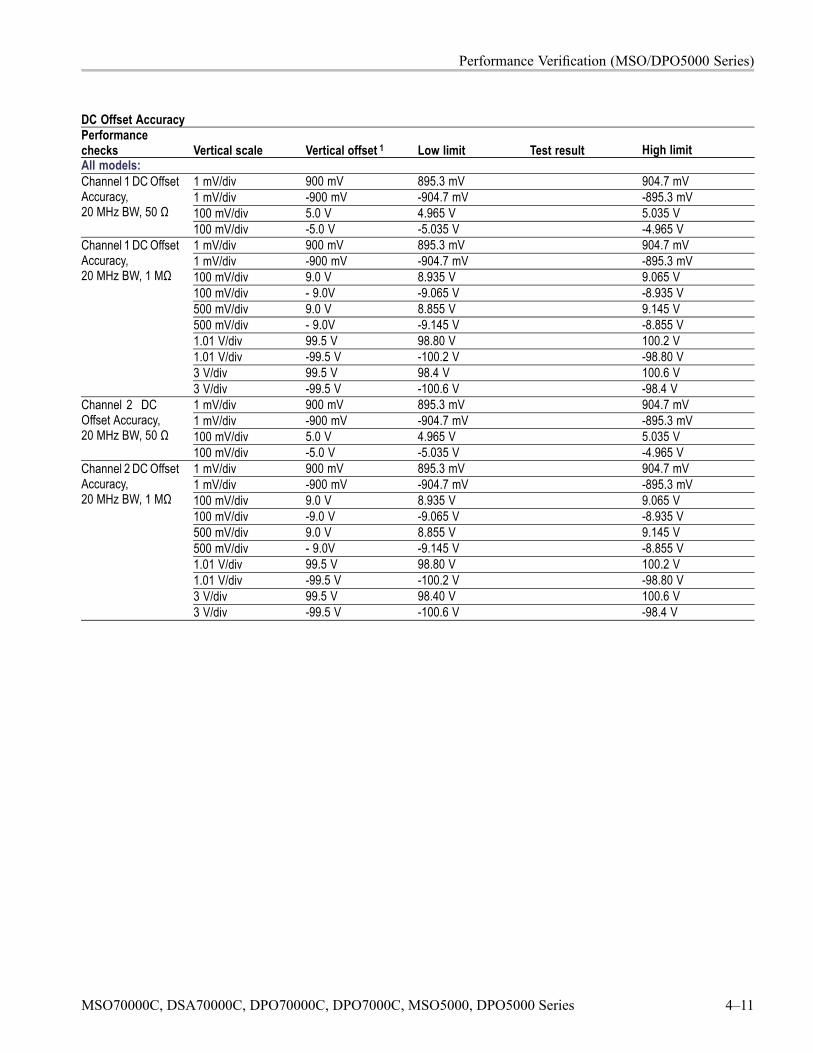
Performance Verification (MSO/DPO5000 Series)
DC Offset AccuracyPerformancechecks Vertical scale Vertical offset 1 Low limit Test result High limitAll models:
1 mV/div 900 mV 895.3 mV 904.7 mV1 mV/div -900 mV -904.7 mV -895.3 mV100 mV/div 5.0 V 4.965 V 5.035 V
Channel 1 DC OffsetAccuracy,20 MHz BW, 50 Ω
100 mV/div -5.0 V -5.035 V -4.965 V1 mV/div 900 mV 895.3 mV 904.7 mV1 mV/div -900 mV -904.7 mV -895.3 mV100 mV/div 9.0 V 8.935 V 9.065 V100 mV/div - 9.0V -9.065 V -8.935 V500 mV/div 9.0 V 8.855 V 9.145 V500 mV/div - 9.0V -9.145 V -8.855 V1.01 V/div 99.5 V 98.80 V 100.2 V1.01 V/div -99.5 V -100.2 V -98.80 V3 V/div 99.5 V 98.4 V 100.6 V
Channel 1 DC OffsetAccuracy,20 MHz BW, 1 MΩ
3 V/div -99.5 V -100.6 V -98.4 V1 mV/div 900 mV 895.3 mV 904.7 mV1 mV/div -900 mV -904.7 mV -895.3 mV100 mV/div 5.0 V 4.965 V 5.035 V
Channel 2 DCOffset Accuracy,20 MHz BW, 50 Ω
100 mV/div -5.0 V -5.035 V -4.965 V1 mV/div 900 mV 895.3 mV 904.7 mV1 mV/div -900 mV -904.7 mV -895.3 mV100 mV/div 9.0 V 8.935 V 9.065 V100 mV/div -9.0 V -9.065 V -8.935 V500 mV/div 9.0 V 8.855 V 9.145 V500 mV/div - 9.0V -9.145 V -8.855 V1.01 V/div 99.5 V 98.80 V 100.2 V1.01 V/div -99.5 V -100.2 V -98.80 V3 V/div 99.5 V 98.40 V 100.6 V
Channel 2 DC OffsetAccuracy,20 MHz BW, 1 MΩ
3 V/div -99.5 V -100.6 V -98.4 V
MSO70000C, DSA70000C, DPO70000C, DPO7000C, MSO5000, DPO5000 Series 4–11
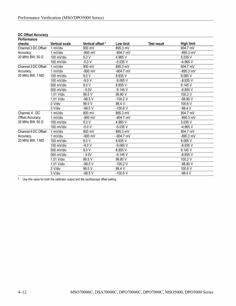
Performance Verification (MSO/DPO5000 Series)
DC Offset AccuracyPerformancechecks Vertical scale Vertical offset 1 Low limit Test result High limit
1 mV/div 900 mV 895.3 mV 904.7 mV1 mV/div -900 mV -904.7 mV -895.3 mV100 mV/div 5.0 V 4.965 V 5.035 V
Channel 3 DC OffsetAccuracy,20 MHz BW, 50 Ω
100 mV/div -5.0 V -5.035 V -4.965 V1 mV/div 900 mV 895.3 mV 904.7 mV1 mV/div -900 mV -904.7 mV -895.3 mV100 mV/div 9.0 V 8.935 V 9.065 V100 mV/div -9.0 V -9.065 V -8.935 V500 mV/div 9.0 V 8.855 V 9.145 V500 mV/div - 9.0V -9.145 V -8.855 V1.01 V/div 99.5 V 98.80 V 100.2 V1.01 V/div -99.5 V -100.2 V -98.80 V3 V/div 99.5 V 98.4 V 100.6 V
Channel 3 DC OffsetAccuracy,20 MHz BW, 1 MΩ
3 V/div -99.5 V -100.6 V -98.4 V1 mV/div 900 mV 895.3 mV 904.7 mV1 mV/div -900 mV -904.7 mV -895.3 mV100 mV/div 5.0 V 4.965 V 5.035 V
Channel 4 DCOffset Accuracy,20 MHz BW, 50 Ω
100 mV/div -5.0 V -5.035 V -4.965 V1 mV/div 900 mV 895.3 mV 904.7 mV1 mV/div -900 mV -904.7 mV -895.3 mV100 mV/div 9.0 V 8.935 V 9.065 V100 mV/div -9.0 V -9.065 V -8.935 V500 mV/div 9.0 V 8.855 V 9.145 V500 mV/div - 9.0V -9.145 V -8.855 V1.01 V/div 99.5 V 98.80 V 100.2 V1.01 V/div -99.5 V -100.2 V -98.80 V3 V/div 99.5 V 98.4 V 100.6 V
Channel 4 DC OffsetAccuracy,20 MHz BW, 1 MΩ
3 V/div -99.5 V -100.6 V -98.4 V1 Use this value for both the calibrator output and the oscilloscope offset setting.
4–12 MSO70000C, DSA70000C, DPO70000C, DPO7000C, MSO5000, DPO5000 Series

Performance Verification (MSO/DPO5000 Series)
Analog BandwidthPerformance checksBandwidthatChannel Impedance Vertical scale
Horizontalscale Vin-pp Vbw-pp Limit
Test resultGain = Vbw-pp/Vin-pp
All Models1 mV/div 5 ns/div
(175 MHz)≥ 0.707
2 mV/div 2.5 ns/div(350 MHz)
≥ 0.707
5 mV/div 1 ns/div(Full BW)
≥ 0.707
10 mV/div 1 ns/div(Full BW)
≥ 0.707
50 mV/div 1 ns/div(Full BW)
≥ 0.707
100 mV/div 1 ns/div(Full BW)
≥ 0.707
Channel 1 50 Ω
1 V/div 1 ns/div(Full BW)
≥ 0.707
MSO5204, DPO5204, MSO5104, DPO5104 Only1 mV/div 5 ns/div
(175 MHz)≥ 0.707
2 mV/div 2.5 ns/div(350 MHz)
≥ 0.707
5 mV/div 1 ns/div(Full BW)
≥ 0.707
10 mV/div 1 ns/div(Full BW)
≥ 0.707
50 mV/div 1 ns/div(Full BW)
≥ 0.707
100 mV/div 1 ns/div(Full BW)
≥ 0.707
Channel 1 1 MΩ
1 V/div 1 ns/div(Full BW)
≥ 0.707
MSO70000C, DSA70000C, DPO70000C, DPO7000C, MSO5000, DPO5000 Series 4–13
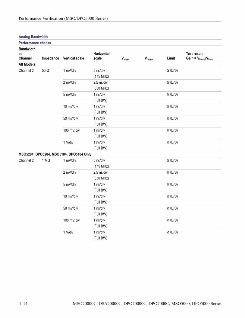
Performance Verification (MSO/DPO5000 Series)
Analog BandwidthPerformance checksBandwidthatChannel Impedance Vertical scale
Horizontalscale Vin-pp Vbw-pp Limit
Test resultGain = Vbw-pp/Vin-pp
All Models1 mV/div 5 ns/div
(175 MHz)≥ 0.707
2 mV/div 2.5 ns/div(350 MHz)
≥ 0.707
5 mV/div 1 ns/div(Full BW)
≥ 0.707
10 mV/div 1 ns/div(Full BW)
≥ 0.707
50 mV/div 1 ns/div(Full BW)
≥ 0.707
100 mV/div 1 ns/div(Full BW)
≥ 0.707
Channel 2 50 Ω
1 V/div 1 ns/div(Full BW)
≥ 0.707
MSO5204, DPO5204, MSO5104, DPO5104 Only1 mV/div 5 ns/div
(175 MHz)≥ 0.707
2 mV/div 2.5 ns/div(350 MHz)
≥ 0.707
5 mV/div 1 ns/div(Full BW)
≥ 0.707
10 mV/div 1 ns/div(Full BW)
≥ 0.707
50 mV/div 1 ns/div(Full BW)
≥ 0.707
100 mV/div 1 ns/div(Full BW)
≥ 0.707
Channel 2 1 MΩ
1 V/div 1 ns/div(Full BW)
≥ 0.707
4–14 MSO70000C, DSA70000C, DPO70000C, DPO7000C, MSO5000, DPO5000 Series
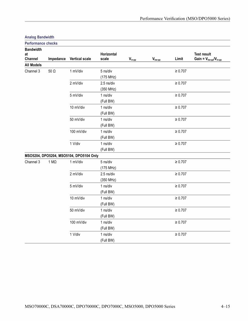
Performance Verification (MSO/DPO5000 Series)
Analog BandwidthPerformance checksBandwidthatChannel Impedance Vertical scale
Horizontalscale Vin-pp Vbw-pp Limit
Test resultGain = Vbw-pp/Vin-pp
All Models1 mV/div 5 ns/div
(175 MHz)≥ 0.707
2 mV/div 2.5 ns/div(350 MHz)
≥ 0.707
5 mV/div 1 ns/div(Full BW)
≥ 0.707
10 mV/div 1 ns/div(Full BW)
≥ 0.707
50 mV/div 1 ns/div(Full BW)
≥ 0.707
100 mV/div 1 ns/div(Full BW)
≥ 0.707
Channel 3 50 Ω
1 V/div 1 ns/div(Full BW)
≥ 0.707
MSO5204, DPO5204, MSO5104, DPO5104 Only1 mV/div 5 ns/div
(175 MHz)≥ 0.707
2 mV/div 2.5 ns/div(350 MHz)
≥ 0.707
5 mV/div 1 ns/div(Full BW)
≥ 0.707
10 mV/div 1 ns/div(Full BW)
≥ 0.707
50 mV/div 1 ns/div(Full BW)
≥ 0.707
100 mV/div 1 ns/div(Full BW)
≥ 0.707
Channel 3 1 MΩ
1 V/div 1 ns/div(Full BW)
≥ 0.707
MSO70000C, DSA70000C, DPO70000C, DPO7000C, MSO5000, DPO5000 Series 4–15

Performance Verification (MSO/DPO5000 Series)
Analog BandwidthPerformance checksBandwidthatChannel Impedance Vertical scale
Horizontalscale Vin-pp Vbw-pp Limit
Test resultGain = Vbw-pp/Vin-pp
All Models1 mV/div 5 ns/div
(175 MHz)≥ 0.707
2 mV/div 2.5 ns/div(350 MHz)
≥ 0.707
5 mV/div 1 ns/div(Full BW)
≥ 0.707
10 mV/div 1 ns/div(Full BW)
≥ 0.707
50 mV/div 1 ns/div(Full BW)
≥ 0.707
100 mV/div 1 ns/div(Full BW)
≥ 0.707
Channel 4 50 Ω
1 V/div 1 ns/div(Full BW)
≥ 0.707
MSO5204, DPO5204, MSO5104, DPO5104 Only1 mV/div 5 ns/div
(175 MHz)≥ 0.707
2 mV/div 2.5 ns/div(350 MHz)
≥ 0.707
5 mV/div 1 ns/div(Full BW)
≥ 0.707
10 mV/div 1 ns/div(Full BW)
≥ 0.707
50 mV/div 1 ns/div(Full BW)
≥ 0.707
100 mV/div 1 ns/div(Full BW)
≥ 0.707
Channel 4 1 MΩ
1 V/div 1 ns/div(Full BW)
≥ 0.707
4–16 MSO70000C, DSA70000C, DPO70000C, DPO7000C, MSO5000, DPO5000 Series
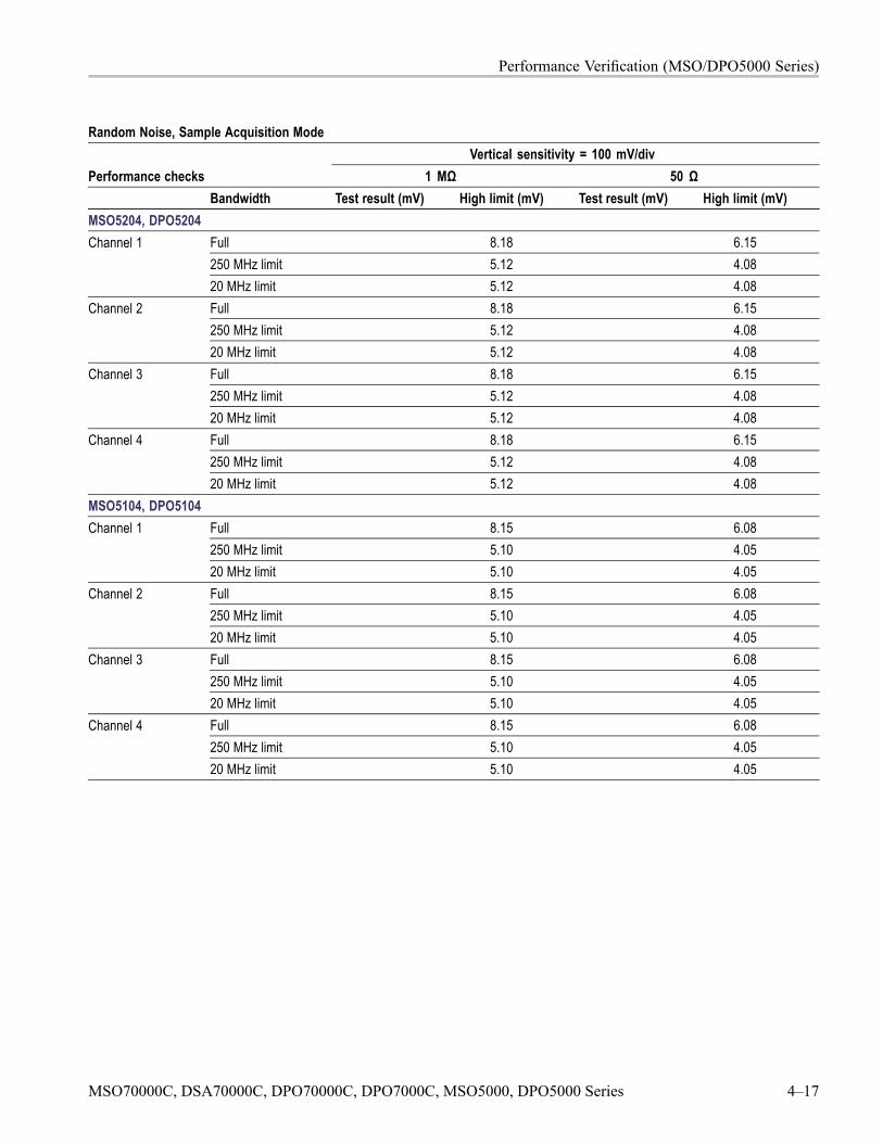
Performance Verification (MSO/DPO5000 Series)
Random Noise, Sample Acquisition ModeVertical sensitivity = 100 mV/div
Performance checks 1 MΩ 50 ΩBandwidth Test result (mV) High limit (mV) Test result (mV) High limit (mV)
MSO5204, DPO5204Full 8.18 6.15250 MHz limit 5.12 4.08
Channel 1
20 MHz limit 5.12 4.08Full 8.18 6.15250 MHz limit 5.12 4.08
Channel 2
20 MHz limit 5.12 4.08Full 8.18 6.15250 MHz limit 5.12 4.08
Channel 3
20 MHz limit 5.12 4.08Full 8.18 6.15250 MHz limit 5.12 4.08
Channel 4
20 MHz limit 5.12 4.08MSO5104, DPO5104
Full 8.15 6.08250 MHz limit 5.10 4.05
Channel 1
20 MHz limit 5.10 4.05Full 8.15 6.08250 MHz limit 5.10 4.05
Channel 2
20 MHz limit 5.10 4.05Full 8.15 6.08250 MHz limit 5.10 4.05
Channel 3
20 MHz limit 5.10 4.05Full 8.15 6.08250 MHz limit 5.10 4.05
Channel 4
20 MHz limit 5.10 4.05
MSO70000C, DSA70000C, DPO70000C, DPO7000C, MSO5000, DPO5000 Series 4–17
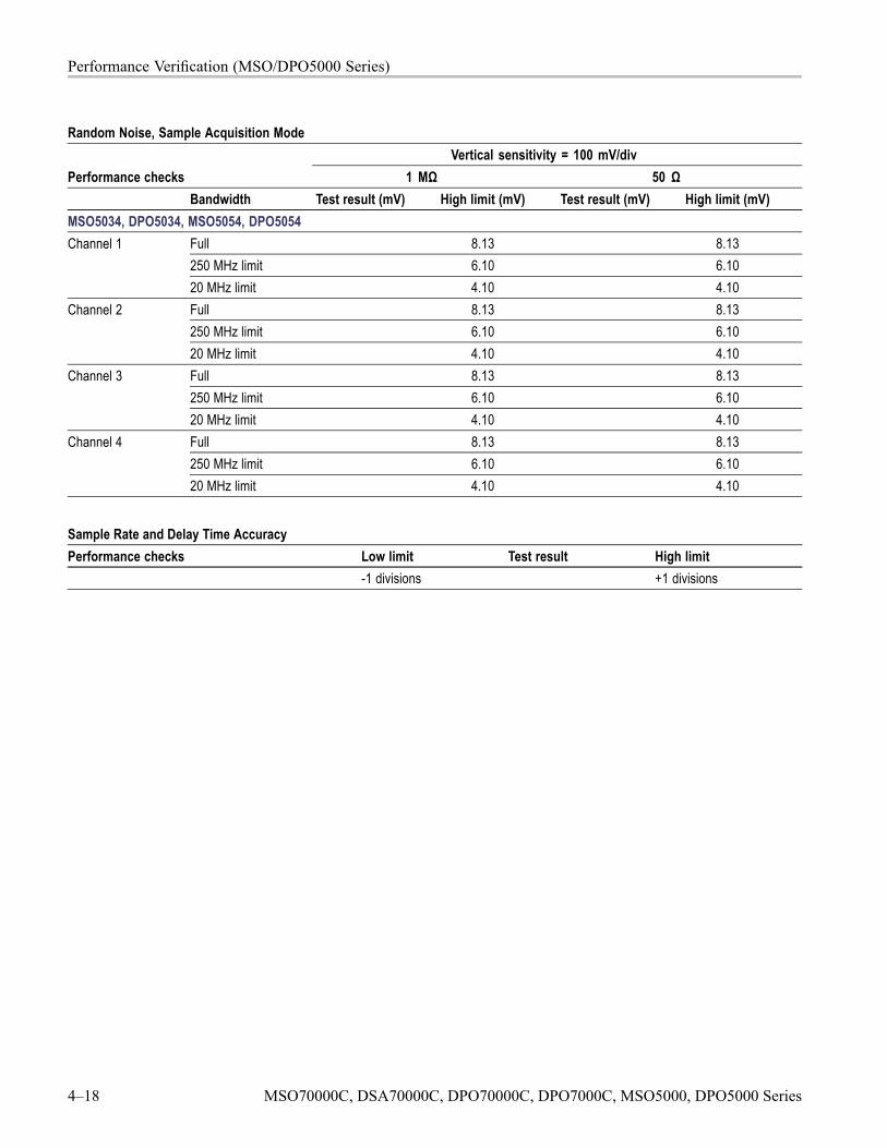
Performance Verification (MSO/DPO5000 Series)
Random Noise, Sample Acquisition ModeVertical sensitivity = 100 mV/div
Performance checks 1 MΩ 50 ΩBandwidth Test result (mV) High limit (mV) Test result (mV) High limit (mV)
MSO5034, DPO5034, MSO5054, DPO5054Full 8.13 8.13250 MHz limit 6.10 6.10
Channel 1
20 MHz limit 4.10 4.10Full 8.13 8.13250 MHz limit 6.10 6.10
Channel 2
20 MHz limit 4.10 4.10Full 8.13 8.13250 MHz limit 6.10 6.10
Channel 3
20 MHz limit 4.10 4.10Full 8.13 8.13250 MHz limit 6.10 6.10
Channel 4
20 MHz limit 4.10 4.10
Sample Rate and Delay Time AccuracyPerformance checks Low limit Test result High limit
-1 divisions +1 divisions
4–18 MSO70000C, DSA70000C, DPO70000C, DPO7000C, MSO5000, DPO5000 Series
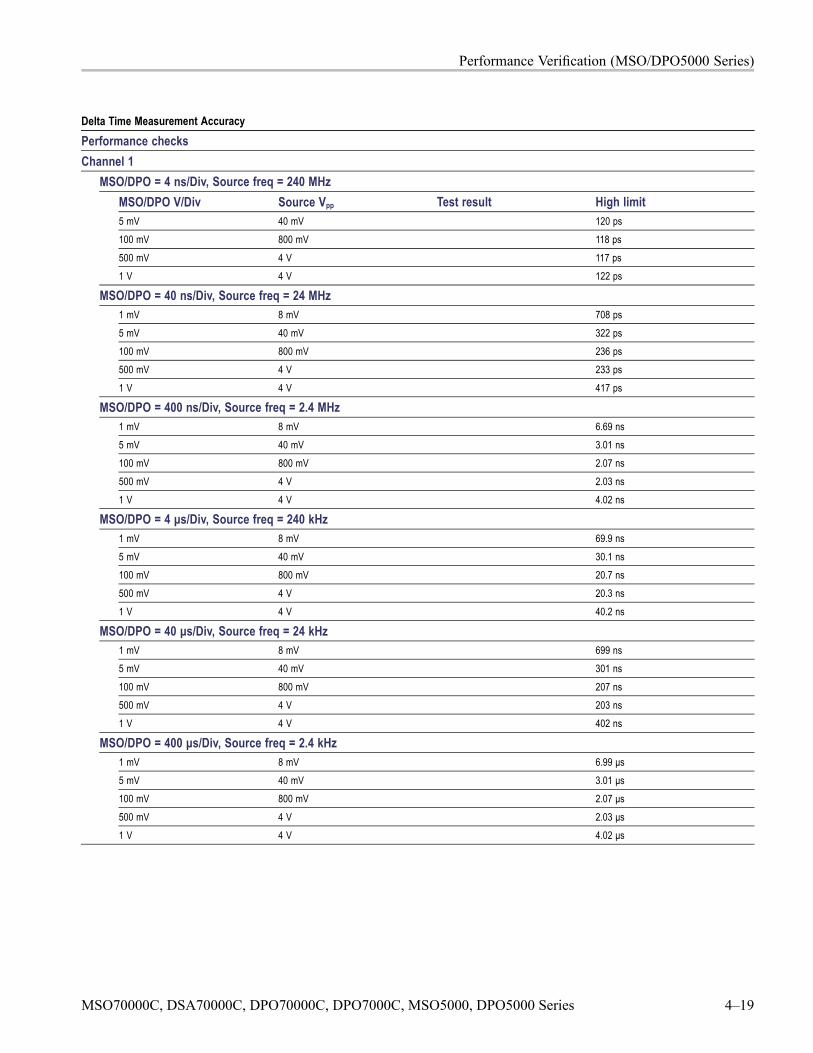
Performance Verification (MSO/DPO5000 Series)
Delta Time Measurement AccuracyPerformance checksChannel 1
MSO/DPO = 4 ns/Div, Source freq = 240 MHzMSO/DPO V/Div Source Vpp Test result High limit5 mV 40 mV 120 ps100 mV 800 mV 118 ps
500 mV 4 V 117 ps1 V 4 V 122 ps
MSO/DPO = 40 ns/Div, Source freq = 24 MHz1 mV 8 mV 708 ps
5 mV 40 mV 322 ps100 mV 800 mV 236 ps500 mV 4 V 233 ps
1 V 4 V 417 ps
MSO/DPO = 400 ns/Div, Source freq = 2.4 MHz1 mV 8 mV 6.69 ns5 mV 40 mV 3.01 ns
100 mV 800 mV 2.07 ns
500 mV 4 V 2.03 ns1 V 4 V 4.02 ns
MSO/DPO = 4 μs/Div, Source freq = 240 kHz1 mV 8 mV 69.9 ns
5 mV 40 mV 30.1 ns100 mV 800 mV 20.7 ns
500 mV 4 V 20.3 ns
1 V 4 V 40.2 ns
MSO/DPO = 40 μs/Div, Source freq = 24 kHz1 mV 8 mV 699 ns5 mV 40 mV 301 ns
100 mV 800 mV 207 ns500 mV 4 V 203 ns1 V 4 V 402 ns
MSO/DPO = 400 μs/Div, Source freq = 2.4 kHz1 mV 8 mV 6.99 μs5 mV 40 mV 3.01 μs100 mV 800 mV 2.07 μs
500 mV 4 V 2.03 μs1 V 4 V 4.02 μs
MSO70000C, DSA70000C, DPO70000C, DPO7000C, MSO5000, DPO5000 Series 4–19
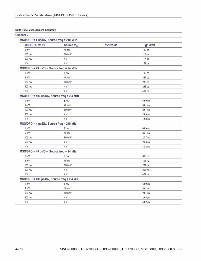
Performance Verification (MSO/DPO5000 Series)
Delta Time Measurement AccuracyChannel 2
MSO/DPO = 4 ns/Div, Source freq = 240 MHzMSO/DPO V/Div Source Vpp Test result High limit5 mV 40 mV 120 ps100 mV 800 mV 118 ps
500 mV 4 V 117 ps1 V 4 V 122 ps
MSO/DPO = 40 ns/Div, Source freq = 24 MHz1 mV 8 mV 708 ps
5 mV 40 mV 322 ps100 mV 800 mV 236 ps500 mV 4 V 233 ps
1 V 4 V 417 ps
MSO/DPO = 400 ns/Div, Source freq = 2.4 MHz1 mV 8 mV 6.99 ns5 mV 40 mV 3.01 ns
100 mV 800 mV 2.07 ns
500 mV 4 V 2.03 ns1 V 4 V 4.02 ns
MSO/DPO = 4 μs/Div, Source freq = 240 kHz1 mV 8 mV 69.9 ns
5 mV 40 mV 30.1 ns100 mV 800 mV 20.7 ns
500 mV 4 V 20.3 ns
1 V 4 V 40.2 ns
MSO/DPO = 40 μs/Div, Source freq = 24 kHz1 mV 8 mV 699 ns
5 mV 40 mV 301 ns
100 mV 800 mV 207 ns500 mV 4 V 203 ns1 V 4 V 402 ns
MSO/DPO = 400 μs/Div, Source freq = 2.4 kHz1 mV 8 mV 6.99 μs5 mV 40 mV 3.01μs100 mV 800 mV 2.07 μs
500 mV 4 V 2.03 μs1 V 4 V 4.02 μs
4–20 MSO70000C, DSA70000C, DPO70000C, DPO7000C, MSO5000, DPO5000 Series
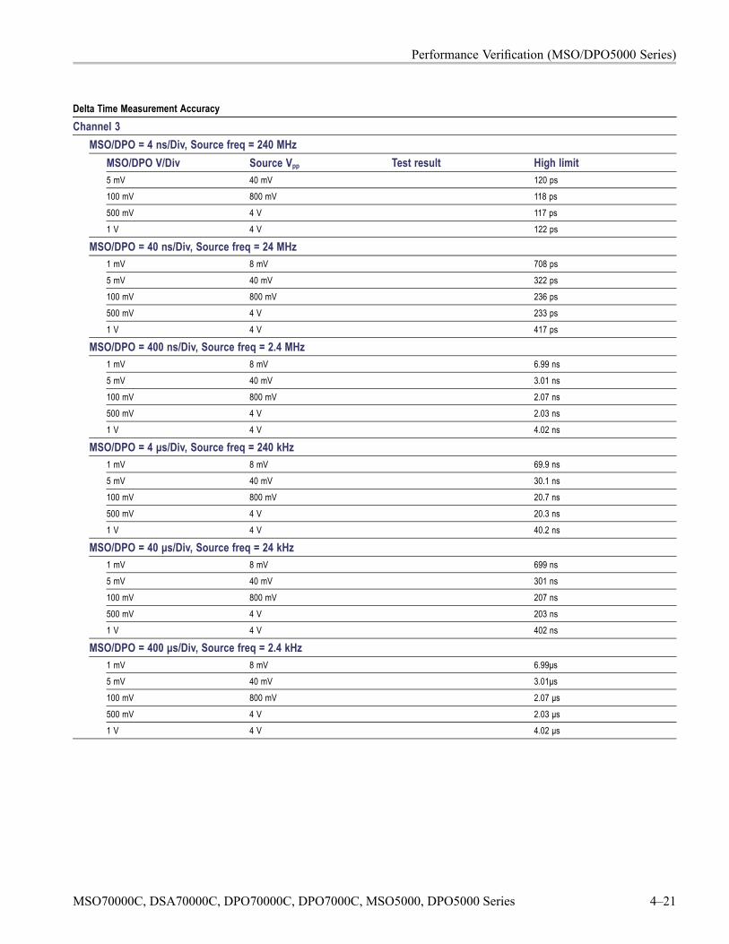
Performance Verification (MSO/DPO5000 Series)
Delta Time Measurement AccuracyChannel 3
MSO/DPO = 4 ns/Div, Source freq = 240 MHzMSO/DPO V/Div Source Vpp Test result High limit5 mV 40 mV 120 ps100 mV 800 mV 118 ps
500 mV 4 V 117 ps1 V 4 V 122 ps
MSO/DPO = 40 ns/Div, Source freq = 24 MHz1 mV 8 mV 708 ps
5 mV 40 mV 322 ps100 mV 800 mV 236 ps500 mV 4 V 233 ps
1 V 4 V 417 ps
MSO/DPO = 400 ns/Div, Source freq = 2.4 MHz1 mV 8 mV 6.99 ns5 mV 40 mV 3.01 ns
100 mV 800 mV 2.07 ns
500 mV 4 V 2.03 ns1 V 4 V 4.02 ns
MSO/DPO = 4 μs/Div, Source freq = 240 kHz1 mV 8 mV 69.9 ns
5 mV 40 mV 30.1 ns100 mV 800 mV 20.7 ns
500 mV 4 V 20.3 ns
1 V 4 V 40.2 ns
MSO/DPO = 40 μs/Div, Source freq = 24 kHz1 mV 8 mV 699 ns
5 mV 40 mV 301 ns
100 mV 800 mV 207 ns500 mV 4 V 203 ns1 V 4 V 402 ns
MSO/DPO = 400 μs/Div, Source freq = 2.4 kHz1 mV 8 mV 6.99μs5 mV 40 mV 3.01μs100 mV 800 mV 2.07 μs
500 mV 4 V 2.03 μs1 V 4 V 4.02 μs
MSO70000C, DSA70000C, DPO70000C, DPO7000C, MSO5000, DPO5000 Series 4–21

Performance Verification (MSO/DPO5000 Series)
Delta Time Measurement AccuracyChannel 4
MSO/DPO = 4 ns/Div, Source freq = 240 MHzMSO/DPO V/Div Source Vpp Test result High limit5 mV 40 mV 120 ps100 mV 800 mV 118 ps
500 mV 4 V 117 ps1 V 4 V 122 ps
MSO/DPO = 40 ns/Div, Source freq = 24 MHz1 mV 8 mV 708 ps
5 mV 40 mV 322 ps100 mV 800 mV 236 ps500 mV 4 V 233 ps
1 V 4 V 417 ps
MSO/DPO = 400 ns/Div, Source freq = 2.4 MHz1 mV 8 mV 6.99 ns5 mV 40 mV 3.01 ns
100 mV 800 mV 2.07 ns
500 mV 4 V 2.03 ns1 V 4 V 4.02 ns
MSO/DPO = 4 μs/Div, Source freq = 240 kHz1 mV 8 mV 69.9 ns
5 mV 40 mV 30.1 ns100 mV 800 mV 20.7 ns
500 mV 4 V 20.3 ns
1 V 4 V 40.2 ns
MSO/DPO = 40 μs/Div, Source freq = 24 kHz1 mV 8 mV 699 ns
5 mV 40 mV 301 ns
100 mV 800 mV 207 ns500 mV 4 V 203 ns1 V 4 V 402 ns
MSO/DPO = 400 μs/Div, Source freq = 2.4 kHz1 mV 8 mV 6.99μs5 mV 40 mV 3.01μs100 mV 800 mV 2.07 μs
500 mV 4 V 2.03 μs1 V 4 V 4.02 μs
4–22 MSO70000C, DSA70000C, DPO70000C, DPO7000C, MSO5000, DPO5000 Series
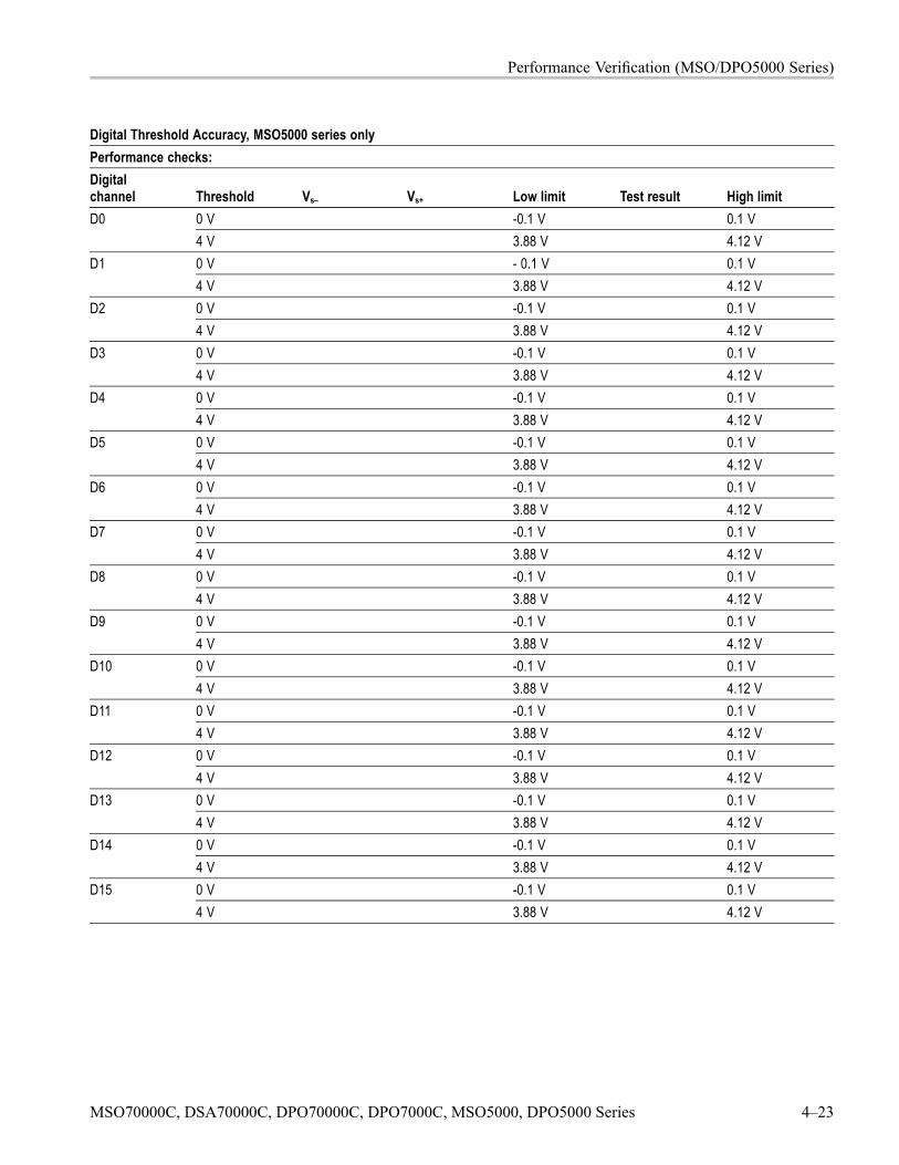
Performance Verification (MSO/DPO5000 Series)
Digital Threshold Accuracy, MSO5000 series onlyPerformance checks:Digitalchannel Threshold Vs– Vs+ Low limit Test result High limit
0 V -0.1 V 0.1 VD04 V 3.88 V 4.12 V0 V - 0.1 V 0.1 VD14 V 3.88 V 4.12 V0 V -0.1 V 0.1 VD24 V 3.88 V 4.12 V0 V -0.1 V 0.1 VD34 V 3.88 V 4.12 V0 V -0.1 V 0.1 VD44 V 3.88 V 4.12 V0 V -0.1 V 0.1 VD54 V 3.88 V 4.12 V0 V -0.1 V 0.1 VD64 V 3.88 V 4.12 V0 V -0.1 V 0.1 VD74 V 3.88 V 4.12 V0 V -0.1 V 0.1 VD84 V 3.88 V 4.12 V0 V -0.1 V 0.1 VD94 V 3.88 V 4.12 V0 V -0.1 V 0.1 VD104 V 3.88 V 4.12 V0 V -0.1 V 0.1 VD114 V 3.88 V 4.12 V0 V -0.1 V 0.1 VD124 V 3.88 V 4.12 V0 V -0.1 V 0.1 VD134 V 3.88 V 4.12 V0 V -0.1 V 0.1 VD144 V 3.88 V 4.12 V0 V -0.1 V 0.1 VD154 V 3.88 V 4.12 V
MSO70000C, DSA70000C, DPO70000C, DPO7000C, MSO5000, DPO5000 Series 4–23
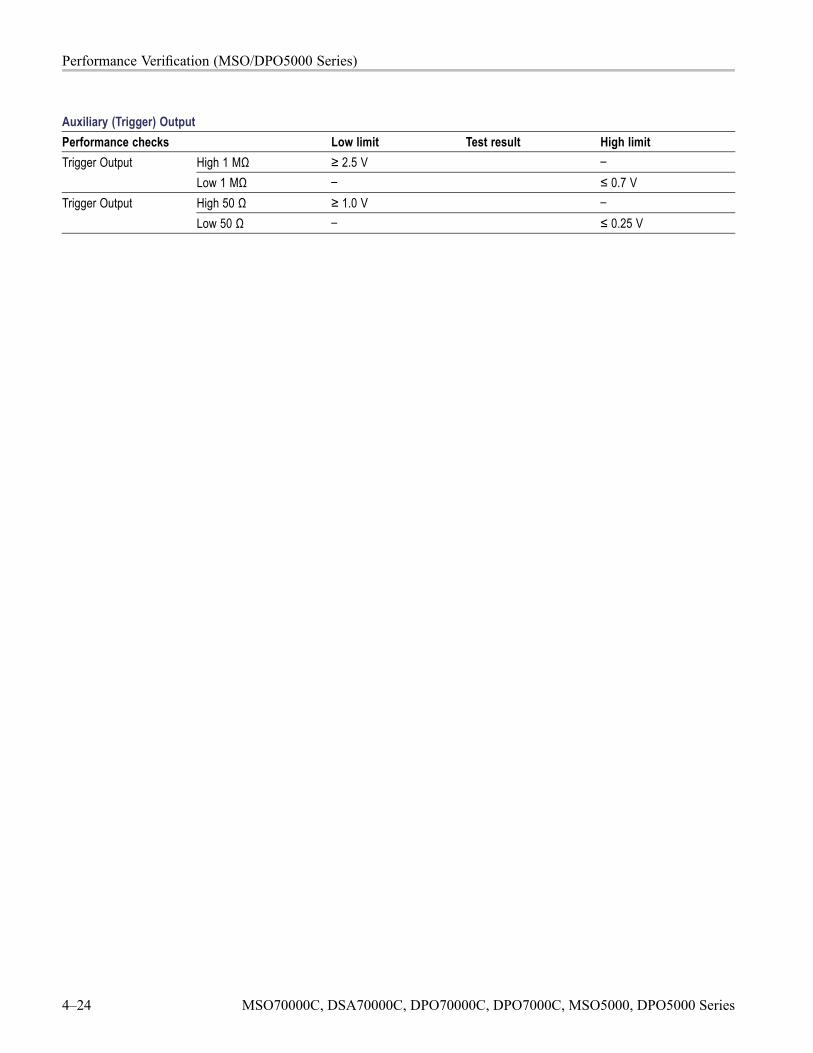
Performance Verification (MSO/DPO5000 Series)
Auxiliary (Trigger) OutputPerformance checks Low limit Test result High limit
High 1 MΩ ≥ 2.5 V –Trigger OutputLow 1 MΩ – ≤ 0.7 VHigh 50 Ω ≥ 1.0 V –Trigger OutputLow 50 Ω – ≤ 0.25 V
4–24 MSO70000C, DSA70000C, DPO70000C, DPO7000C, MSO5000, DPO5000 Series
Performance Tests (MSO/DPO5000 Series)
Performance Tests (MSO/DPO5000 Series)This section contains a collection of manual procedures for checking that theinstrument performs as warranted. They check all the characteristics that aredesignated as checked in Specifications. (The characteristics that are checkedappear with a in Specifications).
PrerequisitesThe tests in this section comprise an extensive, valid confirmation of performanceand functionality when the following requirements are met:
The cabinet must be installed on the instrument.
You must have performed and passed the procedures under Self Test. (Seepage 4-26, Self Test.)
A signal-path compensation must have been done within the recommendedcalibration interval and at a temperature within ±5 ºC (±9 ºF) of the presentoperating temperature. (If at the time you did the prerequisite Self Test, thetemperature was within the limits just stated, consider this prerequisite met).A signal-path compensation must have been done at an ambient humiditywithin 25% of the current ambient humidity and after having been at thathumidity for at least 4 hours.
The instrument must have been last adjusted at an ambient temperaturebetween +18 ºC (+64 ºF) and +28 ºC (+82 ºF), must have been operating for awarm-up period of at least 20 minutes, and must be operating at an ambienttemperature as listed in the specifications. (See Table 2-10 on page 2-17.)(The warm-up requirement is usually met in the course of meeting the SelfTest prerequisites listed above).
Support sensor, probe, and adapter setups to avoid stress or torque whenconnected to the device under test (DUT).
MSO70000C, DSA70000C, DPO70000C, DPO7000C, MSO5000, DPO5000 Series 4–25
Performance Tests (MSO/DPO5000 Series)
Self TestThis procedure verifies that the instrument passes the internal diagnostics andperforms signal path compensation. No test equipment or hookups are required.
Equipment required PrerequisitesNone Power on the instrument and allow a
20 minute warm-up period before performingthis procedure.
1. Run the System Diagnostics (may take several minutes):
a. Ensure that an optical mouse is installed on one of the USB connectors.
b. Disconnect everything from the oscilloscope inputs.
c. If the instrument is in toolbar mode, put the instrument into menu barmode by clicking on the down arrow at the top of the display.
d. Pull down the Utilities menu and select Instrument Diagnostics. Thisdisplays the diagnostics control window.
e. Click the Run button in the diagnostics control window.
f. Wait. The internal diagnostics perform an exhaustive verification ofproper instrument function. This verification may take several minutes.When the verification is finished, the resulting status will appear in thediagnostics control window
g. Verify that the status of all tests on the readout is Pass.
2. Run the signal-path compensation routine (may take 5 to 15 minutes):
a. Pull down the Utilities menu and select Instrument Calibration. Thisdisplays the instrument calibration control window. If required becausethe instrument is in service mode, select the Signal Path button underCalibration Area.
b. Click the Run SPC button to start the routine.
c. Wait. Signal-path compensation may take 5 to 15 minutes to run.
d. Verify that the SPC Status is Pass and that the Temperature Status isReady.
3. Return to regular service: Click the X (close) button to exit the instrumentcalibration control window.
4–26 MSO70000C, DSA70000C, DPO70000C, DPO7000C, MSO5000, DPO5000 Series
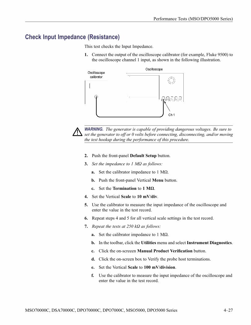
Performance Tests (MSO/DPO5000 Series)
Check Input Impedance (Resistance)This test checks the Input Impedance.
1. Connect the output of the oscilloscope calibrator (for example, Fluke 9500) tothe oscilloscope channel 1 input, as shown in the following illustration.
WARNING. The generator is capable of providing dangerous voltages. Be sure toset the generator to off or 0 volts before connecting, disconnecting, and/or movingthe test hookup during the performance of this procedure.
2. Push the front-panel Default Setup button.
3. Set the impedance to 1 MΩ as follows:
a. Set the calibrator impedance to 1 MΩ.
b. Push the front-panel VerticalMenu button.
c. Set the Termination to 1 MΩ.
4. Set the Vertical Scale to 10 mV/div.
5. Use the calibrator to measure the input impedance of the oscilloscope andenter the value in the test record.
6. Repeat steps 4 and 5 for all vertical scale settings in the test record.
7. Repeat the tests at 250 kΩ as follows:
a. Set the calibrator impedance to 1 MΩ.
b. In the toolbar, click theUtilitiesmenu and select Instrument Diagnostics.
c. Click the on-screeenManual Product Verification button.
d. Click the on-screen box to Verify the probe host terminations.
e. Set the Vertical Scale to 100 mV/division.
f. Use the calibrator to measure the input impedance of the oscilloscope andenter the value in the test record.
MSO70000C, DSA70000C, DPO70000C, DPO7000C, MSO5000, DPO5000 Series 4–27
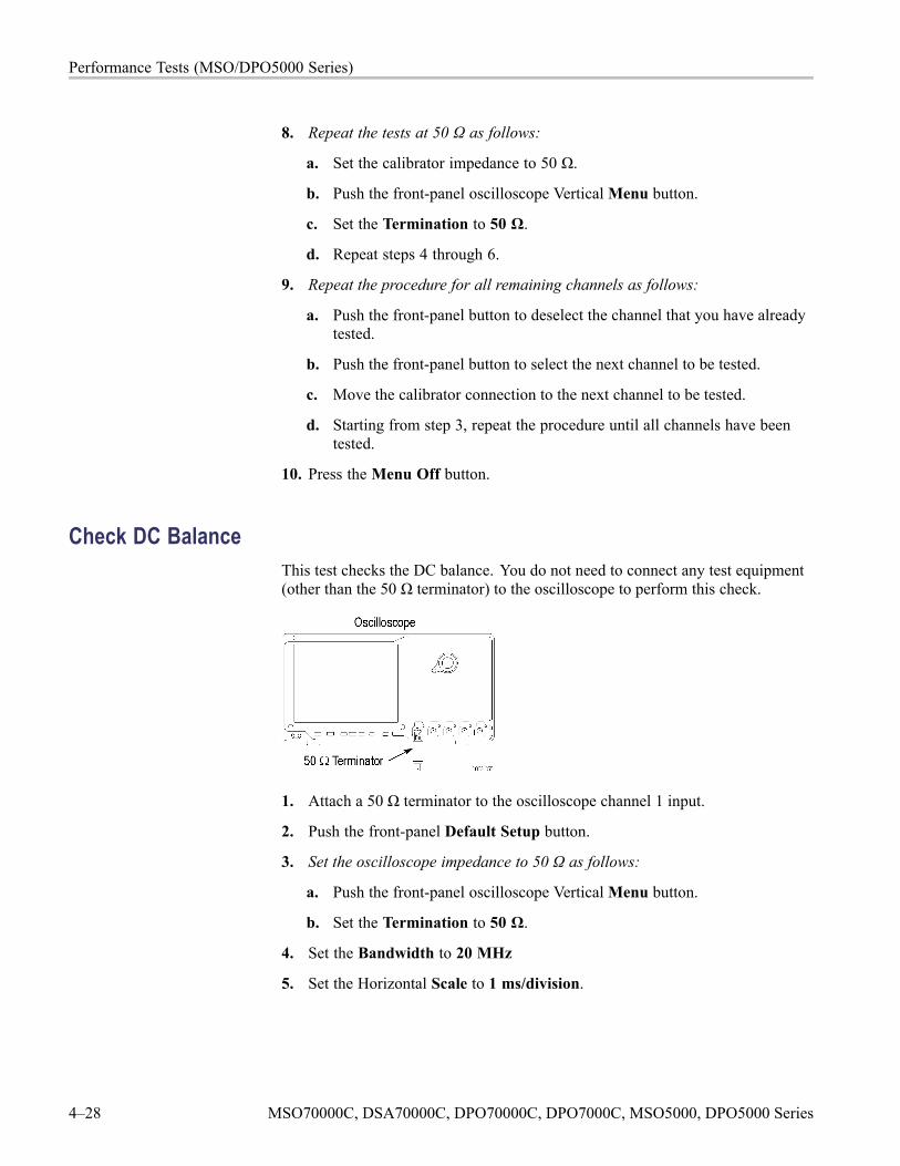
Performance Tests (MSO/DPO5000 Series)
8. Repeat the tests at 50 Ω as follows:
a. Set the calibrator impedance to 50 Ω.
b. Push the front-panel oscilloscope VerticalMenu button.
c. Set the Termination to 50 Ω.
d. Repeat steps 4 through 6.
9. Repeat the procedure for all remaining channels as follows:
a. Push the front-panel button to deselect the channel that you have alreadytested.
b. Push the front-panel button to select the next channel to be tested.
c. Move the calibrator connection to the next channel to be tested.
d. Starting from step 3, repeat the procedure until all channels have beentested.
10. Press the Menu Off button.
Check DC BalanceThis test checks the DC balance. You do not need to connect any test equipment(other than the 50 Ω terminator) to the oscilloscope to perform this check.
1. Attach a 50 Ω terminator to the oscilloscope channel 1 input.
2. Push the front-panel Default Setup button.
3. Set the oscilloscope impedance to 50 Ω as follows:
a. Push the front-panel oscilloscope VerticalMenu button.
b. Set the Termination to 50 Ω.
4. Set the Bandwidth to 20 MHz
5. Set the Horizontal Scale to 1 ms/division.
4–28 MSO70000C, DSA70000C, DPO70000C, DPO7000C, MSO5000, DPO5000 Series
Performance Tests (MSO/DPO5000 Series)
6. Set the Acquisition mode to Average as follows:
a. Push the front-panel Acquire button.
b. In the Acquisition window, select the Acquisition tab at the left.
c. Select Average Acquisition mode.
d. Ensure that the number of averages is set to 16.
7. Set the trigger source to AC line as follows:
a. Push the front-panel TriggerMenu button.
b. In the Trigger menu, under Source, click Select.
c. Click Line to set the trigger source to AC line, and then click OK.
8. Set the Vertical Scale to 1 mV.
9. Select the mean measurement (if not already selected) as follows:
a. Push the front-panel Wave InspectorMeasure button.
b. In the Measurements Setup window, go to theMeasurements box. ClicktheMore button and then selectMean.
c. View theMean measurement value in the display.
10. Enter the mean value as the test result in the test record.
11. Repeat steps 8 through 10 for each vertical scale setting in the test record.
12. Repeat steps 4 through 11 for each bandwidth setting in the test record table.
13. Repeat the tests at 1 MΩ impedance as follows:
a. Push the front-panel VerticalMenu button.
b. Set the Termination to 1M Ω.
c. Repeat steps 4 through 12.
14. Repeat the procedure for all remaining channels as follows:
a. Push the front-panel button to deselect the channel that you have alreadytested.
b. Push the front-panel button to select the next channel to be tested.
c. Move the 50 Ω terminator to the channel input to be tested.
d. Starting from step 3, repeat the procedure until all channels have beentested.
15. Press the Menu Off button.
MSO70000C, DSA70000C, DPO70000C, DPO7000C, MSO5000, DPO5000 Series 4–29
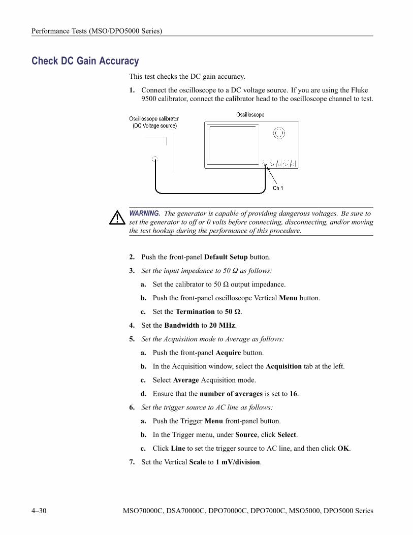
Performance Tests (MSO/DPO5000 Series)
Check DC Gain AccuracyThis test checks the DC gain accuracy.
1. Connect the oscilloscope to a DC voltage source. If you are using the Fluke9500 calibrator, connect the calibrator head to the oscilloscope channel to test.
WARNING. The generator is capable of providing dangerous voltages. Be sure toset the generator to off or 0 volts before connecting, disconnecting, and/or movingthe test hookup during the performance of this procedure.
2. Push the front-panel Default Setup button.
3. Set the input impedance to 50 Ω as follows:
a. Set the calibrator to 50 Ω output impedance.
b. Push the front-panel oscilloscope VerticalMenu button.
c. Set the Termination to 50 Ω.
4. Set the Bandwidth to 20 MHz.
5. Set the Acquisition mode to Average as follows:
a. Push the front-panel Acquire button.
b. In the Acquisition window, select the Acquisition tab at the left.
c. Select Average Acquisition mode.
d. Ensure that the number of averages is set to 16.
6. Set the trigger source to AC line as follows:
a. Push the TriggerMenu front-panel button.
b. In the Trigger menu, under Source, click Select.
c. Click Line to set the trigger source to AC line, and then click OK.
7. Set the Vertical Scale to 1 mV/division.
4–30 MSO70000C, DSA70000C, DPO70000C, DPO7000C, MSO5000, DPO5000 Series
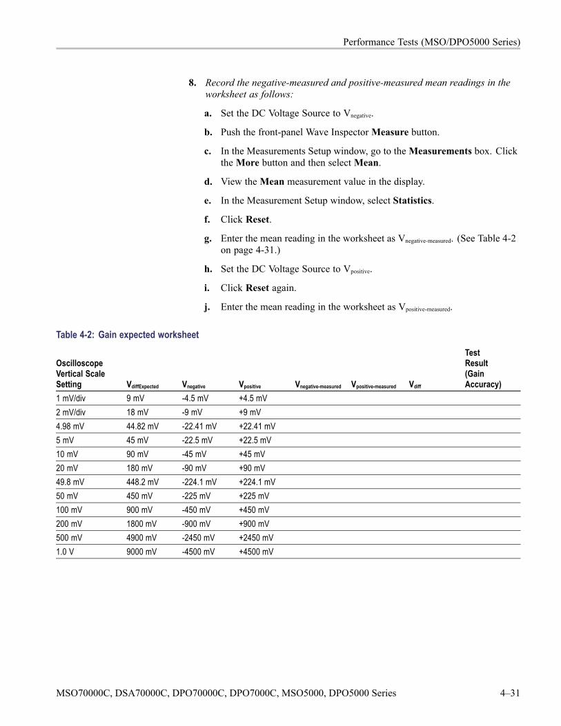
Performance Tests (MSO/DPO5000 Series)
8. Record the negative-measured and positive-measured mean readings in theworksheet as follows:
a. Set the DC Voltage Source to Vnegative.
b. Push the front-panel Wave InspectorMeasure button.
c. In the Measurements Setup window, go to theMeasurements box. ClicktheMore button and then selectMean.
d. View theMean measurement value in the display.
e. In the Measurement Setup window, select Statistics.
f. Click Reset.
g. Enter the mean reading in the worksheet as Vnegative-measured. (See Table 4-2on page 4-31.)
h. Set the DC Voltage Source to Vpositive.
i. Click Reset again.
j. Enter the mean reading in the worksheet as Vpositive-measured.
Table 4-2: Gain expected worksheet
OscilloscopeVertical ScaleSetting VdiffExpected Vnegative Vpositive Vnegative-measured Vpositive-measured Vdiff
TestResult(GainAccuracy)
1 mV/div 9 mV -4.5 mV +4.5 mV2 mV/div 18 mV -9 mV +9 mV4.98 mV 44.82 mV -22.41 mV +22.41 mV5 mV 45 mV -22.5 mV +22.5 mV10 mV 90 mV -45 mV +45 mV20 mV 180 mV -90 mV +90 mV49.8 mV 448.2 mV -224.1 mV +224.1 mV50 mV 450 mV -225 mV +225 mV100 mV 900 mV -450 mV +450 mV200 mV 1800 mV -900 mV +900 mV500 mV 4900 mV -2450 mV +2450 mV1.0 V 9000 mV -4500 mV +4500 mV
MSO70000C, DSA70000C, DPO70000C, DPO7000C, MSO5000, DPO5000 Series 4–31
Performance Tests (MSO/DPO5000 Series)
9. Record Gain Accuracy as follows:
a. Calculate Vdiff as follows:
Vdiff = | Vnegative-measured - Vpositive-measured |
b. Enter Vdiff in the worksheet. (See Table 4-2 on page 4-31.)
c. Calculate Gain Accuracy as follows:
Gain Accuracy = ((Vdiff - VdiffExpected )/ VdiffExpected ) ≥ 100%
d. Enter Gain Accuracy in the worksheet and in the test record.
10. Repeat tests at 1 MΩ impedance as follows:
a. Set the calibrator to 1 MΩ output.
b. Push the front-panel VerticalMenu button.
c. Set the Termination to 1 MΩ
d. Repeat steps 8 through 9.
11. Repeat steps 7 through 10 for all vertical scale settings in the test record.
12. Repeat the procedure for all remaining channels:
a. Push the front-panel button to deselect the channel that you have alreadytested.
b. Push the front-panel button to select the next channel to be tested.
c. Move the DC voltage source connection to the channel input to be tested.
d. Starting from step 3, repeat the procedure until all channels have beentested.
13. Press the Menu Off button.
4–32 MSO70000C, DSA70000C, DPO70000C, DPO7000C, MSO5000, DPO5000 Series
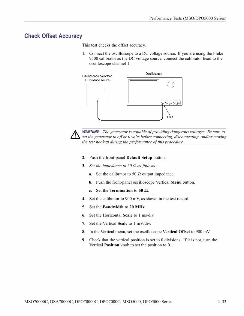
Performance Tests (MSO/DPO5000 Series)
Check Offset AccuracyThis test checks the offset accuracy.
1. Connect the oscilloscope to a DC voltage source. If you are using the Fluke9500 calibrator as the DC voltage source, connect the calibrator head to theoscilloscope channel 1.
WARNING. The generator is capable of providing dangerous voltages. Be sure toset the generator to off or 0 volts before connecting, disconnecting, and/or movingthe test hookup during the performance of this procedure.
2. Push the front-panel Default Setup button.
3. Set the impedance to 50 Ω as follows:
a. Set the calibrator to 50 Ω output impedance.
b. Push the front-panel oscilloscope VerticalMenu button.
c. Set the Termination to 50 Ω.
4. Set the calibrator to 900 mV, as shown in the test record.
5. Set the Bandwidth to 20 MHz.
6. Set the Horizontal Scale to 1 ms/div.
7. Set the Vertical Scale to 1 mV/div.
8. In the Vertical menu, set the oscilloscope Vertical Offset to 900 mV.
9. Check that the vertical position is set to 0 divisions. If it is not, turn theVertical Position knob to set the position to 0.
MSO70000C, DSA70000C, DPO70000C, DPO7000C, MSO5000, DPO5000 Series 4–33
Performance Tests (MSO/DPO5000 Series)
10. Set the Acquisition mode to Average as follows:
a. Push the front-panel Acquire button.
b. In the Acquisition window, select the Acquisition tab at the left.
c. Click Average Acquisition mode.
d. Ensure that the number of averages is set to 16.
11. Set the trigger source to AC line as follows:
a. Push the TriggerMenu front-panel button.
b. In the Trigger menu, under Source, click Select.
c. Click Line to set the trigger source to AC line, and then click OK.
12. Select the mean measurement as follows:
a. Push the front-panel Wave InspectorMeasure button.
b. In the Measurements Setup window, go to theMeasurements box. ClicktheMore button and then selectMean.
c. View theMean measurement value in the display.
13. Enter the mean value as the test result in the test record.
14. Repeat step 13 for each vertical scale and vertical offset setting shown inthe test record.
15. Repeat the tests at 1 MΩ impedance as follows:
a. Change the calibrator impedance to 1 MΩ.
b. Push the front-panel VerticalMenu button.
c. Set the Termination to 1 MΩ.
d. Repeat steps 4 through 14.
16. Repeat the procedure for all remaining channels as follows:
a. Push the front-panel button to deselect the channel that you have alreadytested.
b. Push the front-panel button to select the next channel to be tested.
c. Move the DC voltage source connection to the channel input to be tested.
d. Starting from step 3, repeat the procedure until all channels have beentested.
17. Press the Menu Off button.
4–34 MSO70000C, DSA70000C, DPO70000C, DPO7000C, MSO5000, DPO5000 Series
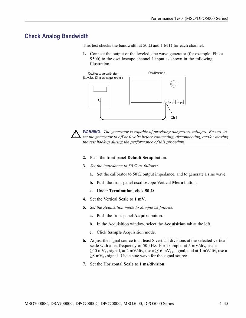
Performance Tests (MSO/DPO5000 Series)
Check Analog BandwidthThis test checks the bandwidth at 50 Ω and 1 M Ω for each channel.
1. Connect the output of the leveled sine wave generator (for example, Fluke9500) to the oscilloscope channel 1 input as shown in the followingillustration.
WARNING. The generator is capable of providing dangerous voltages. Be sure toset the generator to off or 0 volts before connecting, disconnecting, and/or movingthe test hookup during the performance of this procedure.
2. Push the front-panel Default Setup button.
3. Set the impedance to 50 Ω as follows:
a. Set the calibrator to 50 Ω output impedance, and to generate a sine wave.
b. Push the front-panel oscilloscope VerticalMenu button.
c. Under Termination, click 50 Ω.
4. Set the Vertical Scale to 1 mV.
5. Set the Acquisition mode to Sample as follows:
a. Push the front-panel Acquire button.
b. In the Acquisition window, select the Acquisition tab at the left.
c. Click Sample Acquisition mode.
6. Adjust the signal source to at least 8 vertical divisions at the selected verticalscale with a set frequency of 50 kHz. For example, at 5 mV/div, use a≥40 mVp-p signal, at 2 mV/div, use a ≥16 mVp-p signal, and at 1 mV/div, use a≥8 mVp-p signal. Use a sine wave for the signal source.
7. Set the Horizontal Scale to 1 ms/division.
MSO70000C, DSA70000C, DPO70000C, DPO7000C, MSO5000, DPO5000 Series 4–35
Performance Tests (MSO/DPO5000 Series)
8. Record the peak-to-peak measurement as follows:
a. Push the front-panel Wave InspectorMeasure button.
b. In theMeasurements box, click Pk-Pk.
c. This will provide a mean Vp-p of the signal. Call this value Vin-pp.
d. Enter this value in the test record.
9. Set the Horizontal Scale to 5 ns/division.
10. Adjust the signal source to the maximum bandwidth frequency for thebandwidth and model desired, as shown in the following worksheet.
11. Record the peak-to-peak measurement as follows:
a. With the Pk-Pk measurement still displayed from step 8, view themeasurement at the new frequency.
b. This will provide a mean Vp-p of the signal. Call this value Vbw-pp.
c. Enter this value in the test record.
NOTE. For more information on the contents of this worksheet, refer to thebandwidth specifications. (See Table 2-1 on page 2-1.)
4–36 MSO70000C, DSA70000C, DPO70000C, DPO7000C, MSO5000, DPO5000 Series
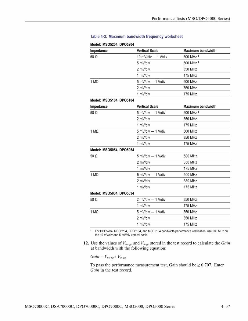
Performance Tests (MSO/DPO5000 Series)
Table 4-3: Maximum bandwidth frequency worksheetModel: MSO5204, DPO5204Impedance Vertical Scale Maximum bandwidth
10 mV/div — 1 V/div 500 MHz 1
5 mV/div 500 MHz 1
2 mV/div 350 MHz
50 Ω
1 mV/div 175 MHz5 mV/div — 1 V/div 500 MHz2 mV/div 350 MHz
1 MΩ
1 mV/div 175 MHzModel: MSO5104, DPO5104Impedance Vertical Scale Maximum bandwidth
5 mV/div — 1 V/div 500 MHz 1
2 mV/div 350 MHz50 Ω
1 mV/div 175 MHz5 mV/div — 1 V/div 500 MHz2 mV/div 350 MHz
1 MΩ
1 mV/div 175 MHzModel: MSO5054, DPO5054
5 mV/div — 1 V/div 500 MHz2 mV/div 350 MHz
50 Ω
1 mV/div 175 MHz5 mV/div — 1 V/div 500 MHz2 mV/div 350 MHz
1 MΩ
1 mV/div 175 MHzModel: MSO5034, DPO5034
2 mV/div — 1 V/div 350 MHz50 Ω1 mV/div 175 MHz5 mV/div — 1 V/div 350 MHz2 mV/div 350 MHz
1 MΩ
1 mV/div 175 MHz1 For DPO5204, MSO5204, DPO5104, and MSO5104 bandwidth performance verification, use 500 MHz on
the 10 mV/div and 5 mV/div vertical scale.
12. Use the values of Vbw-pp and Vin-pp stored in the test record to calculate the Gainat bandwidth with the following equation:
Gain = Vbw-pp / Vin-pp
To pass the performance measurement test, Gain should be ≥ 0.707. EnterGain in the test record.
MSO70000C, DSA70000C, DPO70000C, DPO7000C, MSO5000, DPO5000 Series 4–37
Performance Tests (MSO/DPO5000 Series)
13. Repeat steps 4 through 12 for all combinations of Vertical Scale andHorizontal Scale settings listed in the test record.
14. For MSO/DPO5204 and MSO/DPO5104 models only, repeat the tests at1 MΩ impedance as follows:
a. Change the calibrator impedance to 1 MΩ.
b. Push the front-panel VerticalMenu button.
c. Set the Termination to 1 MΩ.
d. Repeat steps 4 through 13.
15. Repeat the procedure for all remaining channels as follows:
a. Push the front-panel button to deselect the channel that you have alreadytested.
b. Push the front-panel button to select the next channel to be tested.
c. Move the calibrator connection to the channel input to be tested.
d. Starting from step 3, repeat the procedure until all channels have beentested.
16. Press the Menu Off button.
Check Random Noise, Sample Acquisition ModeThis test checks random noise at 50 Ω and 1 M Ω for each channel. You do notneed to connect any test equipment to the oscilloscope for this test.
1. Disconnect everything from the oscilloscope inputs.
2. Push the front-panel Default Setup button.
3. Turn Gating off as follows:
a. Push the front-panel Wave InspectorMeasure button.
b. In the Measurement Setup window, click theMore button and then selectGating.
c. Ensure that Off (Full Record) is selected.
4. Select the RMS measurement as follows:
a. Push the front-panel Wave InspectorMeasure button.
b. In the Measurement Setup window, select the RMS measurement.
c. Ensure that the channel being tested is selected in the Channels box.
4–38 MSO70000C, DSA70000C, DPO70000C, DPO7000C, MSO5000, DPO5000 Series
Performance Tests (MSO/DPO5000 Series)
5. Reset the Statistics as follows:
a. Select Statistics.
b. Click Reset.
c. Click OK.
6. Read and make a note of the RMS Mean value. This is the Sampled MeanValue (SMV).
7. Set the Acquisition mode to Average as follows:
a. Push the front-panel Acquire button.
b. In the Acquisition window, select the Acquisition tab at the left.
c. Click to select Average Acquisition mode.
d. Ensure that the number of averages is set to 16.
8. Reset statistics as follows:
a. Push the front-panel Wave InspectorMeasure button.
b. In the Measurement Setup window, select Statistics.
c. Click Reset.
9. Read and make a note of the RMS Mean value. This is the Averaged MeanValue (AMV).
10. Calculate the RMS noise (RMS noise = SMV – AMV), and enter thecalculated RMS noise in the test record.
11. Set the Acquisition mode to Sample as follows:
a. Push the front-panel Acquire button.
b. In the Acquisition window, select the Acquisition tab at the left.
c. Select the Sample Acquisition mode.
12. Repeat the tests at 50 Ω as follows:
a. Push the front-panel oscilloscope VerticalMenu button.
b. Set the Termination to 50 Ω.
c. Repeat steps 5 through 11.
MSO70000C, DSA70000C, DPO70000C, DPO7000C, MSO5000, DPO5000 Series 4–39
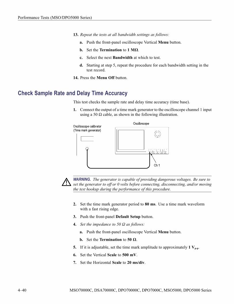
Performance Tests (MSO/DPO5000 Series)
13. Repeat the tests at all bandwidth settings as follows:
a. Push the front-panel oscilloscope VerticalMenu button.
b. Set the Termination to 1 MΩ.
c. Select the next Bandwidth at which to test.
d. Starting at step 5, repeat the procedure for each bandwidth setting in thetest record.
14. Press the Menu Off button.
Check Sample Rate and Delay Time AccuracyThis test checks the sample rate and delay time accuracy (time base).
1. Connect the output of a time mark generator to the oscilloscope channel 1 inputusing a 50 Ω cable, as shown in the following illustration.
WARNING. The generator is capable of providing dangerous voltages. Be sure toset the generator to off or 0 volts before connecting, disconnecting, and/or movingthe test hookup during the performance of this procedure.
2. Set the time mark generator period to 80 ms. Use a time mark waveformwith a fast rising edge.
3. Push the front-panel Default Setup button.
4. Set the impedance to 50 Ω as follows:
a. Push the front-panel oscilloscope VerticalMenu button.
b. Set the Termination to 50 Ω.
5. If it is adjustable, set the time mark amplitude to approximately 1 Vp-p.
6. Set the Vertical Scale to 500 mV.
7. Set the Horizontal Scale to 20 ms/div.
4–40 MSO70000C, DSA70000C, DPO70000C, DPO7000C, MSO5000, DPO5000 Series

Performance Tests (MSO/DPO5000 Series)
8. Set the Vertical Position to center the time mark signal on the screen.
9. Set the Trigger Level as necessary for a triggered display.
10. Adjust the Horizontal Position to move the trigger location to the center ofthe screen (50%).
11. Set the delay to 80 ms as follows:
a. Push the front-panel Acquire button. Ensure that the Horizontal tab onthe left side of the screen is selected.
b. Turn Delay on.
c. Turn the Horizontal Position knob clockwise (or click the Delay box anduse the keypad) to set the delay to exactly 80 ms.
12. Set the horizontal scale to 500 ns/div using the Horizontal Scale knob or byclicking in the Scale box and using the up/down arrows.
13. Compare the rising edge of the marker with the center horizontal graticuleline. The rising edge should be within ±1 divisions of center graticule. Enterthe deviation in the test record.
NOTE. One division of displacement from graticule center corresponds to a5 ppm time base error.
14. Press the Menu Off button.
MSO70000C, DSA70000C, DPO70000C, DPO7000C, MSO5000, DPO5000 Series 4–41
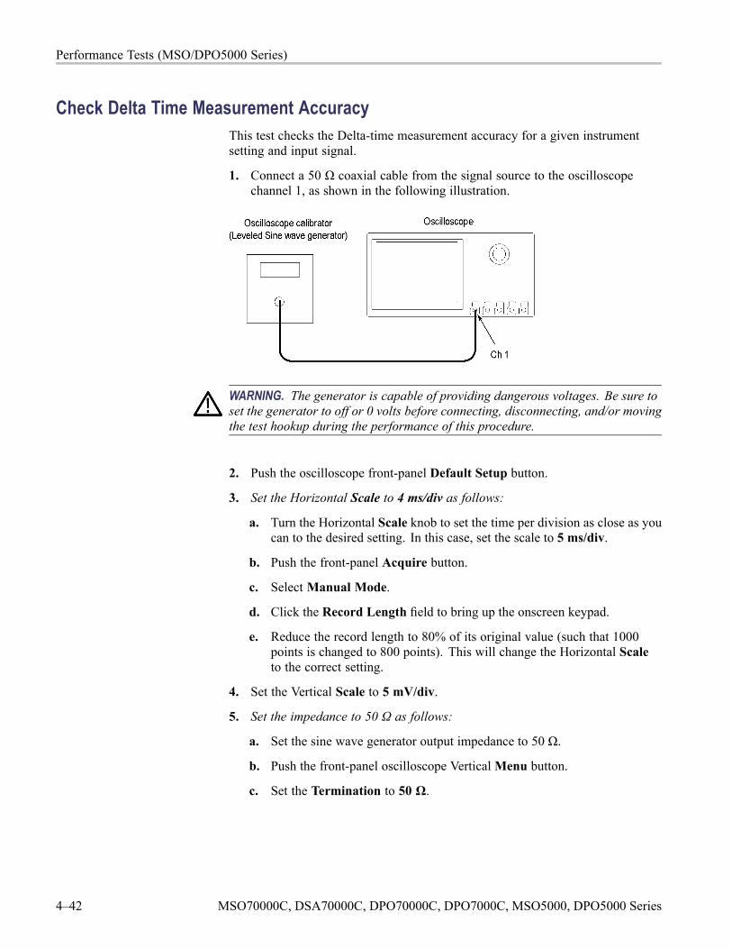
Performance Tests (MSO/DPO5000 Series)
Check Delta Time Measurement AccuracyThis test checks the Delta-time measurement accuracy for a given instrumentsetting and input signal.
1. Connect a 50 Ω coaxial cable from the signal source to the oscilloscopechannel 1, as shown in the following illustration.
WARNING. The generator is capable of providing dangerous voltages. Be sure toset the generator to off or 0 volts before connecting, disconnecting, and/or movingthe test hookup during the performance of this procedure.
2. Push the oscilloscope front-panel Default Setup button.
3. Set the Horizontal Scale to 4 ms/div as follows:
a. Turn the Horizontal Scale knob to set the time per division as close as youcan to the desired setting. In this case, set the scale to 5 ms/div.
b. Push the front-panel Acquire button.
c. Select Manual Mode.
d. Click the Record Length field to bring up the onscreen keypad.
e. Reduce the record length to 80% of its original value (such that 1000points is changed to 800 points). This will change the Horizontal Scaleto the correct setting.
4. Set the Vertical Scale to 5 mV/div.
5. Set the impedance to 50 Ω as follows:
a. Set the sine wave generator output impedance to 50 Ω.
b. Push the front-panel oscilloscope VerticalMenu button.
c. Set the Termination to 50 Ω.
4–42 MSO70000C, DSA70000C, DPO70000C, DPO7000C, MSO5000, DPO5000 Series
Performance Tests (MSO/DPO5000 Series)
6. Set the Mean & St Dev Samples to 1000 as follows:
a. Push the Wave InspectorMeasure button.
b. In the Measurements Setup window, select theMore tab on the left.
c. Select the Burst Width measurement.
d. Select Statistics.
e. Click in theWeight n= box and set the value to 1000.
7. Set the signal source to 240 MHz and 40 mV as shown in the test record.
NOTE. To provide consistent results, set the signal source frequency such that thezero crossing does not occur at the beginning or end of the record.
8. Reset statistics as follows:
a. Push the front-panel Wave InspectorMeasure button.
b. In the Measurement Setup window, select Statistics.
c. Click Reset.
d. Wait 5 or 10 seconds for the oscilloscope to acquire all of the samplesbefore taking the reading.
9. Check the oscilloscope performance as follows:
a. Verify that the St Dev is less than the upper limit shown in the test record.
b. Enter the reading in the test record.
c. Repeat the check for each combination of oscilloscope and source signalsettings in the test record, using the method in step 3 to change theHorizontal Scale settings.
10. Repeat the tests at 1 MΩ as follows:
a. Set the sine wave generator output impedance to 1 MΩ.
b. Push the front-panel oscilloscope VerticalMenu button.
c. Set the Termination to 1 MΩ.
d. Repeat steps 7 through 9 for each setting combination shown in the testrecord.
MSO70000C, DSA70000C, DPO70000C, DPO7000C, MSO5000, DPO5000 Series 4–43
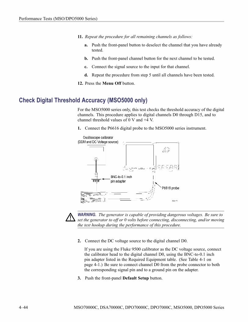
Performance Tests (MSO/DPO5000 Series)
11. Repeat the procedure for all remaining channels as follows:
a. Push the front-panel button to deselect the channel that you have alreadytested.
b. Push the front-panel channel button for the next channel to be tested.
c. Connect the signal source to the input for that channel.
d. Repeat the procedure from step 5 until all channels have been tested.
12. Press the Menu Off button.
Check Digital Threshold Accuracy (MSO5000 only)For the MSO5000 series only, this test checks the threshold accuracy of the digitalchannels. This procedure applies to digital channels D0 through D15, and tochannel threshold values of 0 V and +4 V.
1. Connect the P6616 digital probe to the MSO5000 series instrument.
WARNING. The generator is capable of providing dangerous voltages. Be sure toset the generator to off or 0 volts before connecting, disconnecting, and/or movingthe test hookup during the performance of this procedure.
2. Connect the DC voltage source to the digital channel D0.
If you are using the Fluke 9500 calibrator as the DC voltage source, connectthe calibrator head to the digital channel D0, using the BNC-to-0.1 inchpin adapter listed in the Required Equipment table. (See Table 4-1 onpage 4-1.) Be sure to connect channel D0 from the probe connector to boththe corresponding signal pin and to a ground pin on the adapter.
3. Push the front-panel Default Setup button.
4–44 MSO70000C, DSA70000C, DPO70000C, DPO7000C, MSO5000, DPO5000 Series
Performance Tests (MSO/DPO5000 Series)
4. Turn on the digital channels and set the thresholds as follows:
a. Push the front-panel D15-D0 button.
b. Select the D7-D0 tab on the left and turn channels D7-D0 On.
c. Select the D15-D8 tab and turn channels D15-D8 On.
d. The instrument will display the 16 digital channels.
e. Click in the Global Threshold box and set the value to 0.00 V.
f. Click Apply.
g. All thresholds are now set for the 0 V threshold check.
5. Set the Horizontal Scale to 5 μs/div.
6. Set the source as follows:
a. Push the front-panel Trigger Menu button.
b. Under Source, click Select.
c. In the Source Selection box, select Ch D0. Click OK.
7. Set the DC voltage source (Vs) to -400 mV. Wait 3 seconds. Check the logiclevel of the channel D0 signal display. If it is at a static logic high, change theDC voltage source Vs to -500 mV.
8. Increment Vs by +10 mV. Wait 3 seconds and check the logic level of thechannel D0 signal display. If it is a static logic high, record the Vs valueas in the 0 V row of the test record.
If the signal level is a logic low or is alternating between high and low, repeatthis step (increment Vs by 10 mV, wait 3 seconds, and check for a static logichigh) until a value for Vs- is found.
9. Click the lower Slope button to change the slope to Falling.
10. Set the DC voltage source (Vs) to +400 mV. Wait 3 seconds. Check the logiclevel of the channel D0 signal display.
If it is at a static logic low, change the DC voltage source Vs to +500 mV.
11. Reduce Vs by -10 mV. Wait 3 seconds and check the logic level of the channelD0 signal display. If it is a static logic low, record the Vs value as Vs+ in the0 V row of the test record.
If the signal level is a logic high or is alternating between high and low, repeatthis step (decrement Vs by 10 mV, wait 3 seconds, and check for a static logiclow) until a value for Vs+ is found.
12. Find the average using this formula: VsAvg = (Vs- + Vs+)/2. Record the averageas the test result in the test record.
MSO70000C, DSA70000C, DPO70000C, DPO7000C, MSO5000, DPO5000 Series 4–45
Performance Tests (MSO/DPO5000 Series)
Compare the test result to the limits. If the result is between the limits,continue with the procedure to test the channel at the +4 V threshold value.
13. Begin the +4 V threshold test as follows:
a. Push the front-panel D15-D0 button.
b. Set the D0 Threshold value to 4.00 V (+4.0 V/div).
14. Set the DC voltage source (Vs) to +4.4 V. Wait 3 seconds. Check the logiclevel of the channel D0 signal display.
If it is a static logic low, change the DC voltage source Vs to +4.5 V.
15. Decrement Vs by -10 mV. Wait 3 seconds and check the logic level of thechannel D0 signal display. If it is a static logic low, record the Vs value asVs+ in the 4 V row of the test record.
If the signal level is a logic high or is alternating between high and low, repeatthis step (decrement Vs by 10 mV, wait 3 seconds, and check for a static logiclow) until a value for Vs+ is found.
16. Push the front-panel Trigger Menu button.
17. Click the lower Slope button to change the slope to Rising.
18. Set the DC voltage source (Vs) to +3.6 V. Wait 3 seconds. Check the logiclevel of the channel D0 signal display.
If the signal level is a static logic high, change the DC voltage source Vs to+3.5 V.
19. Increment Vs by +10 mV. Wait 3 seconds and check the logic level of thechannel D0 signal display. If it is a static logic high, record the Vs value in the4 V row of the test record.
If the signal level is a logic low or is alternating between high and low, repeatthis step (increment Vs by 10 mV, wait 3 seconds, and check for a static logichigh) until a value for Vs- is found.
20. Find the average using this formula: VsAvg = (Vs- + Vs+)/2. Record the averageas the test result in the test record.
Compare the test result to the limits. If the result is between the limits, thechannel passes the test.
4–46 MSO70000C, DSA70000C, DPO70000C, DPO7000C, MSO5000, DPO5000 Series
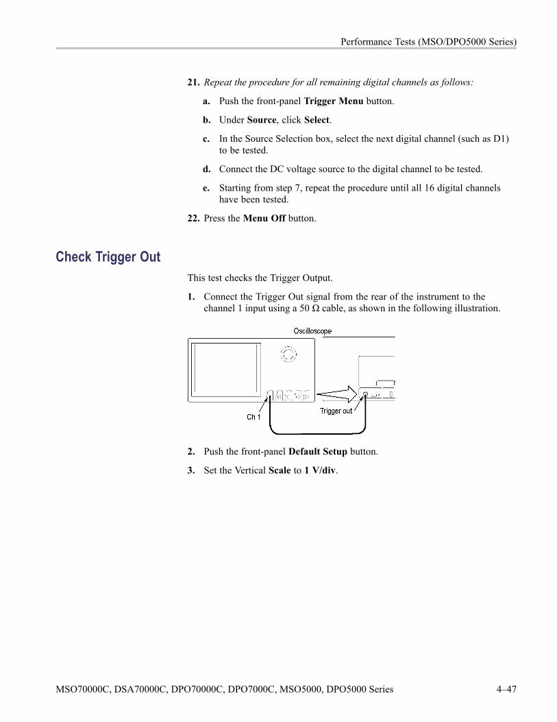
Performance Tests (MSO/DPO5000 Series)
21. Repeat the procedure for all remaining digital channels as follows:
a. Push the front-panel Trigger Menu button.
b. Under Source, click Select.
c. In the Source Selection box, select the next digital channel (such as D1)to be tested.
d. Connect the DC voltage source to the digital channel to be tested.
e. Starting from step 7, repeat the procedure until all 16 digital channelshave been tested.
22. Press the Menu Off button.
Check Trigger OutThis test checks the Trigger Output.
1. Connect the Trigger Out signal from the rear of the instrument to thechannel 1 input using a 50 Ω cable, as shown in the following illustration.
2. Push the front-panel Default Setup button.
3. Set the Vertical Scale to 1 V/div.
MSO70000C, DSA70000C, DPO70000C, DPO7000C, MSO5000, DPO5000 Series 4–47
Performance Tests (MSO/DPO5000 Series)
4. Record the Low and High measurements at 1 MΩ as follows:
a. Push the front-panel Wave InspectorMeasure button.
b. Ensure that the Amplitude tab is selected.
c. Select the Low measurement.
d. Enter the Low measurement reading in the test record.
e. Select the High measurement.
f. Enter the High measurement reading in the test record.
5. Record the Low and High measurements at 50 Ω as follows:
a. Push the front-panel oscilloscope VerticalMenu button.
b. Set the Termination to 50 Ω.
c. Push the front-panel Wave InspectorMeasure button.
d. Ensure that the Amplitude tab is selected.
e. Select the Low measurement.
f. Enter the Low measurement reading in the test record.
g. Select the High measurement.
h. Enter the High measurement reading in the test record.
This completes the performance verification procedure.
4–48 MSO70000C, DSA70000C, DPO70000C, DPO7000C, MSO5000, DPO5000 Series