requirements specification language definitionrequirements specification language definition –...
TRANSCRIPT
Requirements Specification Language DefinitionDefining the ReDSeeDS Languages
Deliverable D2.4.1, version 1.00, 28.02.2007
IST-2006-033596ReDSeeDSRequirements DrivenSoftware Development Systemwww.redseeds.eu
Infovide-Matrix S.A., Poland
Warsaw University of Technology, Poland
Hamburger Informatik Technologie Center e.V., Germany
University of Koblenz-Landau, Germany
University of Latvia, Latvia
Vienna University of Technology, Austria
Fraunhofer IESE, Germany
Algoritmu sistemos, UAB, Lithuania
Cybersoft IT Ltd., Turkey
PRO DV Software AG, Germany
Heriot-Watt University, United Kingdom
Requirements Specification Language DefinitionDefining the ReDSeeDS Languages
Workpackage WP2Task T2.4Document number D2.4.1Document type DeliverableTitle Requirements Specification Language DefinitionSubtitle Defining the ReDSeeDS LanguagesAuthor(s) Hermann Kaindl, Michał Smiałek, Davor Svetinovic, Albert Am-
broziewicz, Jacek Bojarski, Wiktor Nowakowski, Tomasz Straszak,Hannes Schwarz, Daniel Bildhauer, John Paul Brogan, KizitoSsamula Mukasa, Katharina Wolter, Thorsten Krebs
Internal Reviewer(s) Michał Smiałek, Albert Ambroziewicz, Jacek Bojarski, WiktorNowakowski, Tomasz Straszak, John Paul Brogan, Hermann Kaindl,Sevan Kavaldjian, Roman Popp
Internal Acceptance Project BoardLocation https://svn.redseeds.eu/svn/redseeds/1_DeliverablesSpace/WP2_Re-
quirements_specification_language/D2.4.01/ReDSeeDS_D2.4.1_Re-quirements_Specification_Language_Definition.pdf
Version 1.00Status FinalDistribution Public
The information in this document is provided as is and no guarantee or warranty is given that the information is fitfor any particular purpose. The user thereof uses the information at its sole risk and liability.
28.02.2007
Requirements Specification Language Definition – D2.4.1History of changes
ver. 1.0028.02.2007
History of changes
Date Ver. Author(s) Change description13.02.2007 0.01 Hermann Kaindl (TUW) Proposition of ToC
15.02.2007 0.02 Hannes Schwarz (UKo) Added sections Constrained language rep-resentations, Representation sentences,SVO sentences, Phrases, Terms
15.02.2007 0.03 Hermann Kaindl (TUW) Added content for executive summary
16.02.2007 0.04 Hermann Kaindl (TUW) Added content for Requirements on RSL
16.02.2007 0.05 Albert Ambroziewicz(WUT)
Transferred and updated UIBehaviour de-scription; transferred sections 1.2&1.5
16.02.2007 0.06 Albert Ambroziewicz(WUT)
Added Profiles appendix and profile de-scription for UI devices
16.02.2007 0.07 Michał Smiałek (WUT) Proposition of content for Chapter 6, up-date in Chapter 7
16.02.2007 0.08 Albert Ambroziewicz,Jacek Bojarski (WUT)
Changed document structure
16.02.2007 0.09 Daniel Bildhauer (UKo) Added sections Natural language repre-sentations, Interaction representation, Sys-tem, Actors, Basic domain elements
16.02.2007 0.10 John Paul Brogan (HWU) Added content for Document Scope
16.02.2007 0.11 John Paul Brogan (HWU) Added content for Related work and rela-tions to other documents
16.02.2007 0.12 John Paul Brogan (HWU) Added content for Structure of Document
16.02.2007 0.13 Daniel Bildhauer (UKo) Restructuring of Interaction representa-tions
16.02.2007 0.14 Kizito Ssamula Mukasa(Fraunhofer)
Added profile for user interface elements
16.02.2007 0.15 Hermann Kaindl (TUW) Added content for Domain representationsusing conceptual models
IST-2006-033596 ReDSeeDS: Requirements Driven Software Development System page III
Requirements Specification Language Definition – D2.4.1History of changes
ver. 1.0028.02.2007
Date Ver. Author(s) Change description16.02.2007 0.16 Hermann Kaindl (TUW) Added content for Thesaurus (based on
text by Markus Nick)
16.02.2007 0.17 Hermann Kaindl (TUW) Added content for Conclusion
17.02.2007 0.18 Jacek Bojarski (WUT) Added content for Activity sentences andActivity sentence constructs
19.02.2007 0.19 Albert Ambroziewicz(WUT)
Added content for Kernel package de-scription
19.02.2007 0.20 John Paul Brogan (HWU) Added content for Relations to UML andSysML
20.02.2007 0.21 Tomasz Straszak (WUT) Added content for TermsRelations sectionand updated Terms section
20.02.2007 0.22 Kizito Ssamula Mukasa(Fraunhofer)
Added content for Chap 15
21.02.2007 0.23 Daniel Bildhauer (UKo) Finished all sections dealing with interac-tion representations
21.02.2007 0.24 Albert Ambroziewicz,Tomasz Straszak (WUT)
Major changes in User interface elementssection
21.02.2007 0.25 John Paul Brogan (HWU) Updated content for Relations to UML andSysML and added relevant references
21.02.2007 0.26 Hannes Schwarz (UKo) Added section 12.1
21.02.2007 0.27 Wiktor Nowakowski(WUT)
Added content for Chapter 11
22.02.2007 0.28 Daniel Bildhauer (UKo) Major changes to actors and system ele-ments sections.
22.02.2007 0.29 Jacek Bojarski (WUT) Finished all sections dealing with activityrepresentations
23.02.2007 0.30 Daniel Bildhauer (UKo) Removed deprecated content and replacedfigures
23.02.2007 0.31 Albert Ambroziewicz(WUT)
Added content for Notions section
23.02.2007 0.32 Jacek Bojarski (WUT) Added content for Scenario sentences sec-tion
23.02.2007 0.33 Tomasz Straszak (WUT) Added content for Domain elements sec-tion
23.02.2007 0.34 Hannes Schwarz (UKo) Added content for Requirement represen-tations section
23.02.2007 0.35 Daniel Bildhauer (UKo) Updated and replaced figures
IST-2006-033596 ReDSeeDS: Requirements Driven Software Development System page IV
Requirements Specification Language Definition – D2.4.1History of changes
ver. 1.0028.02.2007
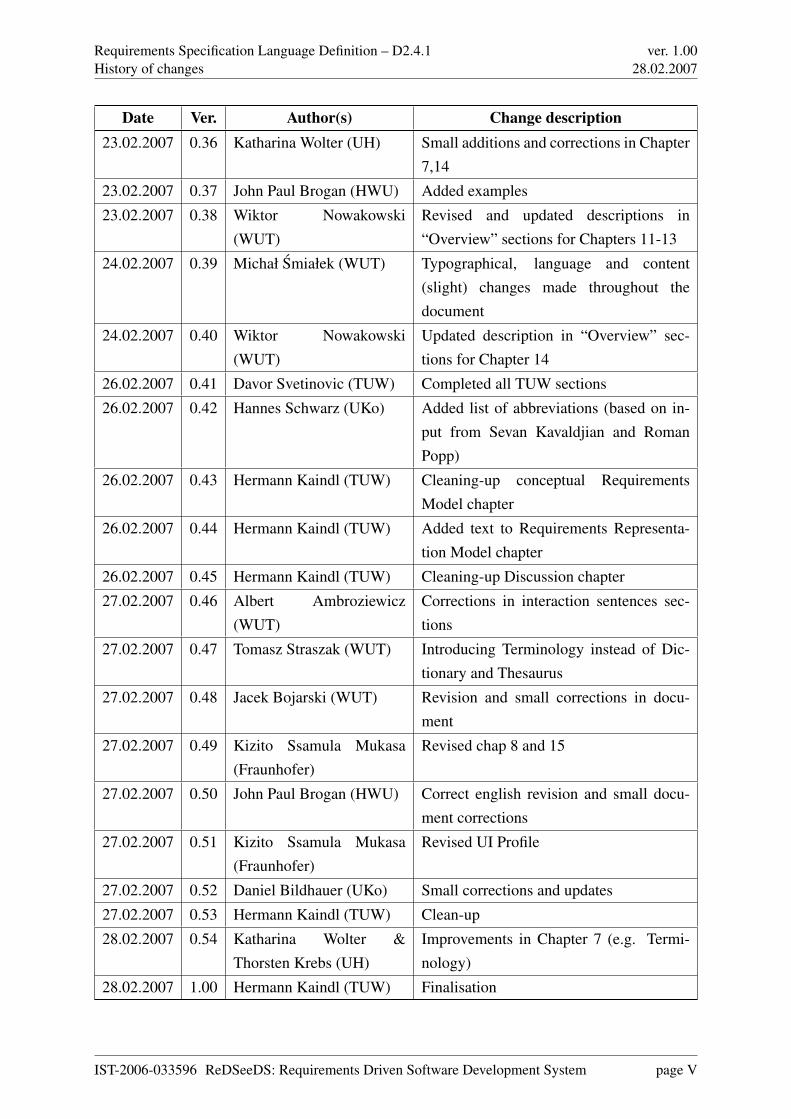
Date Ver. Author(s) Change description23.02.2007 0.36 Katharina Wolter (UH) Small additions and corrections in Chapter
7,14
23.02.2007 0.37 John Paul Brogan (HWU) Added examples
23.02.2007 0.38 Wiktor Nowakowski(WUT)
Revised and updated descriptions in“Overview” sections for Chapters 11-13
24.02.2007 0.39 Michał Smiałek (WUT) Typographical, language and content(slight) changes made throughout thedocument
24.02.2007 0.40 Wiktor Nowakowski(WUT)
Updated description in “Overview” sec-tions for Chapter 14
26.02.2007 0.41 Davor Svetinovic (TUW) Completed all TUW sections
26.02.2007 0.42 Hannes Schwarz (UKo) Added list of abbreviations (based on in-put from Sevan Kavaldjian and RomanPopp)
26.02.2007 0.43 Hermann Kaindl (TUW) Cleaning-up conceptual RequirementsModel chapter
26.02.2007 0.44 Hermann Kaindl (TUW) Added text to Requirements Representa-tion Model chapter
26.02.2007 0.45 Hermann Kaindl (TUW) Cleaning-up Discussion chapter
27.02.2007 0.46 Albert Ambroziewicz(WUT)
Corrections in interaction sentences sec-tions
27.02.2007 0.47 Tomasz Straszak (WUT) Introducing Terminology instead of Dic-tionary and Thesaurus
27.02.2007 0.48 Jacek Bojarski (WUT) Revision and small corrections in docu-ment
27.02.2007 0.49 Kizito Ssamula Mukasa(Fraunhofer)
Revised chap 8 and 15
27.02.2007 0.50 John Paul Brogan (HWU) Correct english revision and small docu-ment corrections
27.02.2007 0.51 Kizito Ssamula Mukasa(Fraunhofer)
Revised UI Profile
27.02.2007 0.52 Daniel Bildhauer (UKo) Small corrections and updates
27.02.2007 0.53 Hermann Kaindl (TUW) Clean-up
28.02.2007 0.54 Katharina Wolter &Thorsten Krebs (UH)
Improvements in Chapter 7 (e.g. Termi-nology)
28.02.2007 1.00 Hermann Kaindl (TUW) Finalisation
IST-2006-033596 ReDSeeDS: Requirements Driven Software Development System page V
Requirements Specification Language Definition – D2.4.1Summary
ver. 1.0028.02.2007
Summary
Requirements specification languages are abundant in the field of Requirements Engineering.However, most of them focus on formal representation only and are not used much in practice.Others provide a subset of natural language only and do not provide means for conceptualmodelling. So, natural language is still the most widely used language for writing requirementsspecifications in practice. Generally, requirements specification languages do not integrate user-interface specifications, although requirements and user interfaces have a lot to do with eachother.
Therefore, we defined a new language, the ReDSeeDS Requirements Specification Language
(RSL). Our approach is intended to be comprehensive for practical use and includes, therefore,even unconstrained natural language. RSL integrates descriptions — constrained and uncon-strained —, conceptual modelling — based on object-oriented ideas — and even user-interfacespecifications. RSL is, however, not simply an aggregation of existing concepts and languageconstructs. It has several distinguished and even unique features.
The behavioural part of RSL distinguishes between Functional and Behavioural Requirements.While the former specify the required effects of some system, the latter specify required be-haviour across the system border, in the form of Envisioned Scenarios. Functional Require-ments are further specialised into Functional Requirements on Composite System and Func-tional Requirements on System to be built. The former are fulfilled by an Envisioned Scenario,while the functions of the latter will make its execution possible. Related Envisioned Scenariostogether make up a Use Case.
The structural part of RSL deals with models and descriptions of objects existing in the domain(environment) of the software system to be built — domain objects. These objects are part of aconceptual Domain Model (to-be). In addition, the concepts can (and should) be described in adefined vocabulary with phrases, containing terms which are organised in a terminology repre-sentation that integrates a dictionary with a thesaurus. RSL is the first language that integrates
IST-2006-033596 ReDSeeDS: Requirements Driven Software Development System page VI
Requirements Specification Language Definition – D2.4.1Summary
ver. 1.0028.02.2007
conceptual modelling with thesaurus features. The descriptions facilitate a better understandingof the concepts, which in turn facilitates a better understanding of the requirements.
We distinguish strictly between requirements and representations of requirements. Strictlyspeaking, only the latter can actually be reused. Requirements representations can be descrip-
tive or model-based, and our RSL language makes this distinction explicit. The former describethe needs of certain requirements, while the latter represent models of the system to be built. Arequirement is then to build a system like the one modelled.
The user-interface part of RSL contains language features for specifying user-interface elementsand their dynamics. It deals with descriptions of various user-interface elements that can expressvarious graphical or other types of elements existing in a user interface. It also includes user-interface storyboards that show dynamic change in the user interface.
Based on the previous deliverables D2.1, D2.2 and D2.3, this deliverable contains a comprehen-sive description of RSL. First, it gives a conceptual overview and explanation of the approachand the language. In the second part, it provides a complete language reference including con-crete syntax.
IST-2006-033596 ReDSeeDS: Requirements Driven Software Development System page VII
Requirements Specification Language Definition – D2.4.1Table of contents
ver. 1.0028.02.2007
Table of contents
History of changes III
Summary VI
Table of contents VIII
List of figures XIII
1 Scope, conventions and guidelines 11.1 Document scope . . . . . . . . . . . . . . . . . . . . . . . . . . . . . . . . . . 11.2 Approach to language definition and notation conventions . . . . . . . . . . . . 2
1.2.1 Meta-modelling . . . . . . . . . . . . . . . . . . . . . . . . . . . . . . 21.2.2 Defining languages using meta-modelling . . . . . . . . . . . . . . . . 41.2.3 Relations to UML and SysML . . . . . . . . . . . . . . . . . . . . . . 51.2.4 Structure of the language reference . . . . . . . . . . . . . . . . . . . . 61.2.5 Notation conventions . . . . . . . . . . . . . . . . . . . . . . . . . . . 7
1.3 Related work and relations to other documents . . . . . . . . . . . . . . . . . . 71.3.1 Model Based User Interface Development . . . . . . . . . . . . . . . . 91.3.2 User Interface Description Languages . . . . . . . . . . . . . . . . . . 101.3.3 Task and Object Oriented Requirement Engineering . . . . . . . . . . . 11
1.4 Structure of this Document . . . . . . . . . . . . . . . . . . . . . . . . . . . . 131.5 Usage guidelines . . . . . . . . . . . . . . . . . . . . . . . . . . . . . . . . . 14
I Conceptual Overview of the Coherent Requirements Language 16
2 Introduction 17
3 Requirements for the requirements language 193.1 Functional Requirements . . . . . . . . . . . . . . . . . . . . . . . . . . . . . 193.2 Constraint Requirements . . . . . . . . . . . . . . . . . . . . . . . . . . . . . 20
4 Requirements Model 214.1 Requirements Model Overview . . . . . . . . . . . . . . . . . . . . . . . . . . 24
IST-2006-033596 ReDSeeDS: Requirements Driven Software Development System page VIII
Requirements Specification Language Definition – D2.4.1Table of contents
ver. 1.0028.02.2007
4.2 Requirements Model Details . . . . . . . . . . . . . . . . . . . . . . . . . . . 254.3 Why No Goals? . . . . . . . . . . . . . . . . . . . . . . . . . . . . . . . . . . 30
5 Requirements Representation Model 325.1 Requirements Representation Model Overview . . . . . . . . . . . . . . . . . 325.2 Requirements Representation Model Details . . . . . . . . . . . . . . . . . . . 33
6 Domain entities 366.1 Business entities . . . . . . . . . . . . . . . . . . . . . . . . . . . . . . . . . . 376.2 System entities . . . . . . . . . . . . . . . . . . . . . . . . . . . . . . . . . . 38
7 Representation of domains 407.1 Overview . . . . . . . . . . . . . . . . . . . . . . . . . . . . . . . . . . . . . 407.2 Domain representations using conceptual models . . . . . . . . . . . . . . . . 437.3 Domain representation using phrases . . . . . . . . . . . . . . . . . . . . . . . 447.4 Terminology . . . . . . . . . . . . . . . . . . . . . . . . . . . . . . . . . . . . 45
8 Representing the user interface and its dynamics 478.1 Elements of the user interface . . . . . . . . . . . . . . . . . . . . . . . . . . . 478.2 Behaviour of the user interface . . . . . . . . . . . . . . . . . . . . . . . . . . 48
9 Discussion 50
II Language Reference 53
10 Kernel 5410.1 Overview . . . . . . . . . . . . . . . . . . . . . . . . . . . . . . . . . . . . . 5410.2 Attributes . . . . . . . . . . . . . . . . . . . . . . . . . . . . . . . . . . . . . 55
10.2.1 Overview . . . . . . . . . . . . . . . . . . . . . . . . . . . . . . . . . 5510.2.2 Abstract syntax and semantics . . . . . . . . . . . . . . . . . . . . . . 5510.2.3 Concrete syntax and examples . . . . . . . . . . . . . . . . . . . . . . 57
10.3 Elements . . . . . . . . . . . . . . . . . . . . . . . . . . . . . . . . . . . . . . 5910.3.1 Overview . . . . . . . . . . . . . . . . . . . . . . . . . . . . . . . . . 5910.3.2 Abstract syntax and semantics . . . . . . . . . . . . . . . . . . . . . . 5910.3.3 Concrete syntax and examples . . . . . . . . . . . . . . . . . . . . . . 62
11 Requirements 6311.1 Overview . . . . . . . . . . . . . . . . . . . . . . . . . . . . . . . . . . . . . 6311.2 Requirements specifications . . . . . . . . . . . . . . . . . . . . . . . . . . . . 67
11.2.1 Overview . . . . . . . . . . . . . . . . . . . . . . . . . . . . . . . . . 6711.2.2 Abstract syntax and semantics . . . . . . . . . . . . . . . . . . . . . . 67
IST-2006-033596 ReDSeeDS: Requirements Driven Software Development System page IX
Requirements Specification Language Definition – D2.4.1Table of contents
ver. 1.0028.02.2007
11.2.3 Concrete syntax and examples . . . . . . . . . . . . . . . . . . . . . . 7111.3 Requirement relationships . . . . . . . . . . . . . . . . . . . . . . . . . . . . . 74
11.3.1 Overview . . . . . . . . . . . . . . . . . . . . . . . . . . . . . . . . . 7411.3.2 Abstract syntax and semantics . . . . . . . . . . . . . . . . . . . . . . 7411.3.3 Concrete syntax and examples . . . . . . . . . . . . . . . . . . . . . . 77
11.4 Use case relationships . . . . . . . . . . . . . . . . . . . . . . . . . . . . . . . 7811.4.1 Overview . . . . . . . . . . . . . . . . . . . . . . . . . . . . . . . . . 7811.4.2 Abstract syntax and semantics . . . . . . . . . . . . . . . . . . . . . . 7811.4.3 Concrete syntax and examples . . . . . . . . . . . . . . . . . . . . . . 80
12 Requirement representations 8212.1 Overview . . . . . . . . . . . . . . . . . . . . . . . . . . . . . . . . . . . . . 8212.2 Requirement representations . . . . . . . . . . . . . . . . . . . . . . . . . . . 86
12.2.1 Overview . . . . . . . . . . . . . . . . . . . . . . . . . . . . . . . . . 8612.2.2 Abstract syntax and semantics . . . . . . . . . . . . . . . . . . . . . . 8812.2.3 Concrete syntax and examples . . . . . . . . . . . . . . . . . . . . . . 89
12.3 Natural language representations . . . . . . . . . . . . . . . . . . . . . . . . . 9012.3.1 Overview . . . . . . . . . . . . . . . . . . . . . . . . . . . . . . . . . 9012.3.2 Abstract syntax and semantics . . . . . . . . . . . . . . . . . . . . . . 9112.3.3 Concrete syntax and examples . . . . . . . . . . . . . . . . . . . . . . 92
12.4 Constrained language representations . . . . . . . . . . . . . . . . . . . . . . . 9212.4.1 Overview . . . . . . . . . . . . . . . . . . . . . . . . . . . . . . . . . 9212.4.2 Abstract syntax and semantics . . . . . . . . . . . . . . . . . . . . . . 9212.4.3 Concrete syntax and examples . . . . . . . . . . . . . . . . . . . . . . 94
12.5 Activity representations . . . . . . . . . . . . . . . . . . . . . . . . . . . . . . 9512.5.1 Overview . . . . . . . . . . . . . . . . . . . . . . . . . . . . . . . . . 9512.5.2 Abstract syntax and semantics . . . . . . . . . . . . . . . . . . . . . . 9512.5.3 Concrete syntax and examples . . . . . . . . . . . . . . . . . . . . . . 96
12.6 Interaction representations . . . . . . . . . . . . . . . . . . . . . . . . . . . . 9712.6.1 Overview . . . . . . . . . . . . . . . . . . . . . . . . . . . . . . . . . 9712.6.2 Abstract syntax and semantics . . . . . . . . . . . . . . . . . . . . . . 9712.6.3 Concrete syntax and examples . . . . . . . . . . . . . . . . . . . . . . 98
13 Requirement representation sentences 10013.1 Overview . . . . . . . . . . . . . . . . . . . . . . . . . . . . . . . . . . . . . 10013.2 Representation sentences . . . . . . . . . . . . . . . . . . . . . . . . . . . . . 102
13.2.1 Overview . . . . . . . . . . . . . . . . . . . . . . . . . . . . . . . . . 10213.2.2 Abstract syntax and semantics . . . . . . . . . . . . . . . . . . . . . . 10213.2.3 Concrete syntax and examples . . . . . . . . . . . . . . . . . . . . . . 104
13.3 SVO sentences . . . . . . . . . . . . . . . . . . . . . . . . . . . . . . . . . . 104
IST-2006-033596 ReDSeeDS: Requirements Driven Software Development System page X
Requirements Specification Language Definition – D2.4.1Table of contents
ver. 1.0028.02.2007
13.3.1 Overview . . . . . . . . . . . . . . . . . . . . . . . . . . . . . . . . . 10413.3.2 Abstract syntax and semantics . . . . . . . . . . . . . . . . . . . . . . 10413.3.3 Concrete syntax and examples . . . . . . . . . . . . . . . . . . . . . . 107
13.4 Scenario sentences . . . . . . . . . . . . . . . . . . . . . . . . . . . . . . . . 10813.4.1 Overview . . . . . . . . . . . . . . . . . . . . . . . . . . . . . . . . . 10813.4.2 Abstract syntax and semantics . . . . . . . . . . . . . . . . . . . . . . 10913.4.3 Concrete syntax and examples . . . . . . . . . . . . . . . . . . . . . . 112
13.5 Activity sentences . . . . . . . . . . . . . . . . . . . . . . . . . . . . . . . . . 11413.5.1 Overview . . . . . . . . . . . . . . . . . . . . . . . . . . . . . . . . . 11413.5.2 Abstract syntax and semantics . . . . . . . . . . . . . . . . . . . . . . 11413.5.3 Concrete syntax and examples . . . . . . . . . . . . . . . . . . . . . . 117
13.6 Activity sentence constructs . . . . . . . . . . . . . . . . . . . . . . . . . . . . 11913.6.1 Overview . . . . . . . . . . . . . . . . . . . . . . . . . . . . . . . . . 11913.6.2 Abstract syntax and semantics . . . . . . . . . . . . . . . . . . . . . . 11913.6.3 Concrete syntax and examples . . . . . . . . . . . . . . . . . . . . . . 121
13.7 Interaction sentences . . . . . . . . . . . . . . . . . . . . . . . . . . . . . . . 12113.7.1 Overview . . . . . . . . . . . . . . . . . . . . . . . . . . . . . . . . . 12113.7.2 Abstract syntax and semantics . . . . . . . . . . . . . . . . . . . . . . 12113.7.3 Concrete syntax and examples . . . . . . . . . . . . . . . . . . . . . . 125
13.8 Interaction sentence constructs . . . . . . . . . . . . . . . . . . . . . . . . . . 12713.8.1 Overview . . . . . . . . . . . . . . . . . . . . . . . . . . . . . . . . . 12713.8.2 Abstract syntax and semantics . . . . . . . . . . . . . . . . . . . . . . 12713.8.3 Concrete syntax and examples . . . . . . . . . . . . . . . . . . . . . . 134
14 Domain elements 13714.1 Overview . . . . . . . . . . . . . . . . . . . . . . . . . . . . . . . . . . . . . 13714.2 Domain elements . . . . . . . . . . . . . . . . . . . . . . . . . . . . . . . . . 140
14.2.1 Overview . . . . . . . . . . . . . . . . . . . . . . . . . . . . . . . . . 14014.2.2 Abstract syntax and semantics . . . . . . . . . . . . . . . . . . . . . . 14114.2.3 Concrete syntax and examples . . . . . . . . . . . . . . . . . . . . . . 143
14.3 Notions . . . . . . . . . . . . . . . . . . . . . . . . . . . . . . . . . . . . . . 14514.3.1 Overview . . . . . . . . . . . . . . . . . . . . . . . . . . . . . . . . . 14514.3.2 Abstract syntax and semantics . . . . . . . . . . . . . . . . . . . . . . 14514.3.3 Concrete syntax . . . . . . . . . . . . . . . . . . . . . . . . . . . . . . 148
14.4 System elements . . . . . . . . . . . . . . . . . . . . . . . . . . . . . . . . . . 15114.4.1 Overview . . . . . . . . . . . . . . . . . . . . . . . . . . . . . . . . . 15114.4.2 Abstract syntax and semantics . . . . . . . . . . . . . . . . . . . . . . 15114.4.3 Concrete syntax . . . . . . . . . . . . . . . . . . . . . . . . . . . . . . 153
14.5 Actors . . . . . . . . . . . . . . . . . . . . . . . . . . . . . . . . . . . . . . . 153
IST-2006-033596 ReDSeeDS: Requirements Driven Software Development System page XI
Requirements Specification Language Definition – D2.4.1Table of contents
ver. 1.0028.02.2007
14.5.1 Overview . . . . . . . . . . . . . . . . . . . . . . . . . . . . . . . . . 15314.5.2 Abstract syntax and semantics . . . . . . . . . . . . . . . . . . . . . . 15314.5.3 Concrete syntax . . . . . . . . . . . . . . . . . . . . . . . . . . . . . . 155
14.6 Domain element representations . . . . . . . . . . . . . . . . . . . . . . . . . 15614.6.1 Overview . . . . . . . . . . . . . . . . . . . . . . . . . . . . . . . . . 15614.6.2 Abstract syntax and semantics . . . . . . . . . . . . . . . . . . . . . . 15614.6.3 Concrete syntax . . . . . . . . . . . . . . . . . . . . . . . . . . . . . . 158
14.7 Phrases . . . . . . . . . . . . . . . . . . . . . . . . . . . . . . . . . . . . . . 15914.7.1 Overview . . . . . . . . . . . . . . . . . . . . . . . . . . . . . . . . . 15914.7.2 Abstract syntax and semantics . . . . . . . . . . . . . . . . . . . . . . 15914.7.3 Concrete syntax and examples . . . . . . . . . . . . . . . . . . . . . . 163
14.8 Terms . . . . . . . . . . . . . . . . . . . . . . . . . . . . . . . . . . . . . . . 16414.8.1 Overview . . . . . . . . . . . . . . . . . . . . . . . . . . . . . . . . . 16414.8.2 Abstract syntax and semantics . . . . . . . . . . . . . . . . . . . . . . 16414.8.3 Concrete syntax and examples . . . . . . . . . . . . . . . . . . . . . . 169
14.9 TermsRelations . . . . . . . . . . . . . . . . . . . . . . . . . . . . . . . . . . 17114.9.1 Overview . . . . . . . . . . . . . . . . . . . . . . . . . . . . . . . . . 17114.9.2 Abstract syntax and semantics . . . . . . . . . . . . . . . . . . . . . . 17214.9.3 Concrete syntax and examples . . . . . . . . . . . . . . . . . . . . . . 176
15 User interface elements 17915.1 Overview . . . . . . . . . . . . . . . . . . . . . . . . . . . . . . . . . . . . . 17915.2 Abstract syntax and semantics . . . . . . . . . . . . . . . . . . . . . . . . . . 18015.3 Concrete syntax and examples . . . . . . . . . . . . . . . . . . . . . . . . . . 186
16 User interface behaviour representation 19016.1 Overview . . . . . . . . . . . . . . . . . . . . . . . . . . . . . . . . . . . . . 19016.2 Abstract syntax and semantics . . . . . . . . . . . . . . . . . . . . . . . . . . 19016.3 Concrete syntax and examples . . . . . . . . . . . . . . . . . . . . . . . . . . 192
17 Conclusion 195
A Profiles for User Interface Representation 197A.1 Profile for user interface elements . . . . . . . . . . . . . . . . . . . 197A.2 Profile for devices . . . . . . . . . . . . . . . . . . . . . . . . . . . . 206
B List of abbreviations 209
Bibliography 211
IST-2006-033596 ReDSeeDS: Requirements Driven Software Development System page XII
Requirements Specification Language Definition – D2.4.1List of figures
ver. 1.0028.02.2007
List of figures
1.1 UML meta-modelling example . . . . . . . . . . . . . . . . . . . . . . . . . . 31.2 ReDSeeDS meta-modelling example . . . . . . . . . . . . . . . . . . . . . . . 51.3 The MB-UID Architecture . . . . . . . . . . . . . . . . . . . . . . . . . . . . 101.4 The TORE Framework . . . . . . . . . . . . . . . . . . . . . . . . . . . . . . 11
4.1 Conceptual Requirements Model . . . . . . . . . . . . . . . . . . . . . . . . . 24
5.1 Requirements Representation Model . . . . . . . . . . . . . . . . . . . . . . . 33
6.1 Application Domain Model . . . . . . . . . . . . . . . . . . . . . . . . . . . . 36
7.1 Scenario with separated domain specification . . . . . . . . . . . . . . . . . . 42
8.1 Usage-oriented UIElements . . . . . . . . . . . . . . . . . . . . . . . . . . . . 48
10.1 Overview of packages inside the Kernel part of RSL . . . . . . . . . . . . . . . 5410.2 Attributes . . . . . . . . . . . . . . . . . . . . . . . . . . . . . . . . . . . . . 5510.3 Showing Requirements Attributes on a diagram . . . . . . . . . . . . . . . . . 5710.4 Element representations . . . . . . . . . . . . . . . . . . . . . . . . . . . . . . 5910.5 Element relationships . . . . . . . . . . . . . . . . . . . . . . . . . . . . . . . 6010.6 Element packages . . . . . . . . . . . . . . . . . . . . . . . . . . . . . . . . . 60
11.1 Overview of packages inside the Requirements part of RSL . . . . . . . . . . . 6411.2 Mappings between meta-classes representing requirements from the Require-
ments package and meta-classes from the conceptual model . . . . . . . . . . . 6511.3 Mappings between meta-classes representing requirements relationships from
the Requirements package and meta-classes from the conceptual model . . . . 6611.4 Requirements specifications . . . . . . . . . . . . . . . . . . . . . . . . . . . . 6811.5 Requirement types . . . . . . . . . . . . . . . . . . . . . . . . . . . . . . . . . 6911.6 Requirement example . . . . . . . . . . . . . . . . . . . . . . . . . . . . . . . 7111.7 UseCase example . . . . . . . . . . . . . . . . . . . . . . . . . . . . . . . . . 7211.8 UseCase tree example . . . . . . . . . . . . . . . . . . . . . . . . . . . . . . . 7311.9 RequirementsPackage example . . . . . . . . . . . . . . . . . . . . . . . . . . 7311.10RequirementsPackage tree example . . . . . . . . . . . . . . . . . . . . . . . . 7411.11RequirementsSpecification example . . . . . . . . . . . . . . . . . . . . . . . 74
IST-2006-033596 ReDSeeDS: Requirements Driven Software Development System page XIII
Requirements Specification Language Definition – D2.4.1List of figures
ver. 1.0028.02.2007
11.12RequirementsSpecification tree example . . . . . . . . . . . . . . . . . . . . . 7411.13Requirement relationships . . . . . . . . . . . . . . . . . . . . . . . . . . . . . 7511.14Requirements and requirement relationships concrete syntax example . . . . . 7711.15Use case relationships . . . . . . . . . . . . . . . . . . . . . . . . . . . . . . . 7911.16Use case relationships concrete syntax example . . . . . . . . . . . . . . . . . 81
12.1 Overview of packages inside the RequirementRepresentations part of RSL (genericrepresentations, natural language and constrained language) . . . . . . . . . . . 83
12.2 Overview of packages inside the RequirementRepresentations part of RSL (ac-tivities and interactions) . . . . . . . . . . . . . . . . . . . . . . . . . . . . . . 84
12.3 Main classes in the RequirementRepresentations part with mappings to the con-ceptual model . . . . . . . . . . . . . . . . . . . . . . . . . . . . . . . . . . . 85
12.4 Requirement representation . . . . . . . . . . . . . . . . . . . . . . . . . . . . 8612.5 Requirement representations hierarchy . . . . . . . . . . . . . . . . . . . . . . 8712.6 UseCase representations . . . . . . . . . . . . . . . . . . . . . . . . . . . . . 8812.7 The same scenario in three different representations: ConstrainedLanguageSce-
nario, ActivityScenario and InteractionScenario . . . . . . . . . . . . . . . . . 9012.8 Natural language representations . . . . . . . . . . . . . . . . . . . . . . . . . 9112.9 NaturalLanguageHypertext example . . . . . . . . . . . . . . . . . . . . . . . 9212.10Constrained language representations . . . . . . . . . . . . . . . . . . . . . . . 9312.11Examples of ConstrainedLanguageStatements . . . . . . . . . . . . . . . . . . 9412.12Example of a ConstrainedLanguageScenario . . . . . . . . . . . . . . . . . . . 9512.13Activity representations . . . . . . . . . . . . . . . . . . . . . . . . . . . . . . 9612.14ActivityScenario example . . . . . . . . . . . . . . . . . . . . . . . . . . . . . 9712.15Interaction representation . . . . . . . . . . . . . . . . . . . . . . . . . . . . . 9812.16Interaction representation with sequence diagram . . . . . . . . . . . . . . . . 9912.17Interaction representation with communication diagram . . . . . . . . . . . . . 99
13.1 Overview of packages inside the RequirementRepresentationSentences part ofRSL (representation, SVO and scenario sentences) . . . . . . . . . . . . . . . . 101
13.2 Overview of packages inside the RequirementRepresentationSentences part ofRSL (activity and interaction sentences) . . . . . . . . . . . . . . . . . . . . . 102
13.3 RepresentationSentences . . . . . . . . . . . . . . . . . . . . . . . . . . . . . 10313.4 Example for NaturalLanguageHypertextSentence . . . . . . . . . . . . . . . . 10413.5 SVOSentences . . . . . . . . . . . . . . . . . . . . . . . . . . . . . . . . . . 10513.6 SVOSentence concrete syntax example . . . . . . . . . . . . . . . . . . . . . 10713.7 ModalSVOSentence concrete syntax example . . . . . . . . . . . . . . . . . . 10713.8 ConditionalSentence concrete syntax example . . . . . . . . . . . . . . . . . . 10813.9 Scenario Sentences . . . . . . . . . . . . . . . . . . . . . . . . . . . . . . . . 10913.10Control Sentences . . . . . . . . . . . . . . . . . . . . . . . . . . . . . . . . . 110
IST-2006-033596 ReDSeeDS: Requirements Driven Software Development System page XIV
Requirements Specification Language Definition – D2.4.1List of figures
ver. 1.0028.02.2007
13.11SVOScenarioSentence example . . . . . . . . . . . . . . . . . . . . . . . . . . 11213.12ControlSentence example . . . . . . . . . . . . . . . . . . . . . . . . . . . . . 11313.13PreconditionSentence example . . . . . . . . . . . . . . . . . . . . . . . . . . 11313.14PostconditionSentence example . . . . . . . . . . . . . . . . . . . . . . . . . . 11313.15InvocationSentence example . . . . . . . . . . . . . . . . . . . . . . . . . . . 11413.16ActivityScenarioSentences . . . . . . . . . . . . . . . . . . . . . . . . . . . . 11513.17ActivityControlSentences . . . . . . . . . . . . . . . . . . . . . . . . . . . . . 11613.18ActivitySVOScenarioSentence example . . . . . . . . . . . . . . . . . . . . . 11713.19ActivityConditionSentence example . . . . . . . . . . . . . . . . . . . . . . . 11813.20ActivityInvocationSentence example . . . . . . . . . . . . . . . . . . . . . . . 11813.21ActivityPreconditionSentence example . . . . . . . . . . . . . . . . . . . . . . 11813.22ActivityPostconditionSentence example . . . . . . . . . . . . . . . . . . . . . 11913.23ActivitySVOSentence . . . . . . . . . . . . . . . . . . . . . . . . . . . . . . . 11913.24ActivityScenarioPartition . . . . . . . . . . . . . . . . . . . . . . . . . . . . . 12013.25ActivitySubject and Preditace example . . . . . . . . . . . . . . . . . . . . . . 12113.26InteractionScenarioSentences . . . . . . . . . . . . . . . . . . . . . . . . . . . 12213.27InteractionConditionSentences . . . . . . . . . . . . . . . . . . . . . . . . . . 12313.28InteractionControlSentences . . . . . . . . . . . . . . . . . . . . . . . . . . . 12413.29Concrete syntax of sequence diagram . . . . . . . . . . . . . . . . . . . . . . . 12613.30Concrete syntax of communication diagram . . . . . . . . . . . . . . . . . . . 12613.31InteractionLifelines . . . . . . . . . . . . . . . . . . . . . . . . . . . . . . . . 12813.32InteractionMessages . . . . . . . . . . . . . . . . . . . . . . . . . . . . . . . . 13013.33InteractionPredicateMessages . . . . . . . . . . . . . . . . . . . . . . . . . . . 13113.34InteractionMessageEnds . . . . . . . . . . . . . . . . . . . . . . . . . . . . . 13213.35InteractionSVOScenarioSentences . . . . . . . . . . . . . . . . . . . . . . . . 13313.36Concrete syntax of sequence diagram . . . . . . . . . . . . . . . . . . . . . . . 13413.37Concrete syntax of communication diagram . . . . . . . . . . . . . . . . . . . 135
14.1 Overview of packages inside the DomainEntities part of RSL . . . . . . . . . . 13714.2 Overview of packages inside the DomainEntities part of RSL . . . . . . . . . . 13814.3 Overview of packages inside the DomainEntities part of RSL . . . . . . . . . . 13914.4 DomainSpecification . . . . . . . . . . . . . . . . . . . . . . . . . . . . . . . 14114.5 Relationship of domain elements . . . . . . . . . . . . . . . . . . . . . . . . . 14314.6 Multiplicities of domain elements’ relationships . . . . . . . . . . . . . . . . . 14414.7 DomainSpecification example, normal and tree view . . . . . . . . . . . . . . . 14414.8 Notions . . . . . . . . . . . . . . . . . . . . . . . . . . . . . . . . . . . . . . 14614.9 NotionsPackages . . . . . . . . . . . . . . . . . . . . . . . . . . . . . . . . . 14614.10Notion’s tree view example . . . . . . . . . . . . . . . . . . . . . . . . . . . . 14814.11Notion’s diagram example - notions and their associations . . . . . . . . . . . . 148
IST-2006-033596 ReDSeeDS: Requirements Driven Software Development System page XV
Requirements Specification Language Definition – D2.4.1List of figures
ver. 1.0028.02.2007
14.12Notion’s diagram example - extended view of notions . . . . . . . . . . . . . . 14914.13DomainStatement example . . . . . . . . . . . . . . . . . . . . . . . . . . . . 14914.14Notion’s diagram example - attributes and generalisations . . . . . . . . . . . . 15014.15System elements . . . . . . . . . . . . . . . . . . . . . . . . . . . . . . . . . . 15114.16System package . . . . . . . . . . . . . . . . . . . . . . . . . . . . . . . . . . 15214.17The concrete syntax of system elements and coresponding packages. . . . . . . 15314.18Actor metamodel part . . . . . . . . . . . . . . . . . . . . . . . . . . . . . . . 15414.19Actors package metamodel part . . . . . . . . . . . . . . . . . . . . . . . . . . 15414.20The concrete syntax of actors and actors packages. . . . . . . . . . . . . . . . . 15614.21Domain element representations . . . . . . . . . . . . . . . . . . . . . . . . . 15714.22DomainElementRepresentation’s concrete syntax example . . . . . . . . . . . 15914.23Phrases . . . . . . . . . . . . . . . . . . . . . . . . . . . . . . . . . . . . . . 16014.24PhraseHyperlink . . . . . . . . . . . . . . . . . . . . . . . . . . . . . . . . . . 16214.25Phrase concrete syntax examples . . . . . . . . . . . . . . . . . . . . . . . . . 16314.26SimpleVerbPhrase concrete syntax examples . . . . . . . . . . . . . . . . . . . 16314.27ComplexVerbPhrase concrete syntax examples . . . . . . . . . . . . . . . . . . 16314.28Regular expressions for Phrase and its subclasses. Optional elements are de-
noted by square brackets. . . . . . . . . . . . . . . . . . . . . . . . . . . . . . 16414.29PhraseHyperlink concrete syntax example . . . . . . . . . . . . . . . . . . . . 16414.30Term and its specialisations. . . . . . . . . . . . . . . . . . . . . . . . . . . . . 16514.31Inflections of the Term. . . . . . . . . . . . . . . . . . . . . . . . . . . . . . . 16614.32TermHyperlink and its subclasses . . . . . . . . . . . . . . . . . . . . . . . . . 16614.33Package view: Terminology’s concrete syntax. . . . . . . . . . . . . . . . . . . 16914.34Terminology tree view example . . . . . . . . . . . . . . . . . . . . . . . . . . 17014.35Synonym and homonym Terms’s relations. . . . . . . . . . . . . . . . . . . . . 17214.36Specialisation Relations of terms from the same type. . . . . . . . . . . . . . . 17314.37Part of a Terminology in abstract syntax with organisation-specific extension
(only Nouns are presented in this figure.) . . . . . . . . . . . . . . . . . . . . . 17714.38Part of a Terminology in abstract syntax with organisation-specific extension
(only Verbs are presented in this figure). . . . . . . . . . . . . . . . . . . . . . 178
15.1 Overview of packages containing elements for the representation of the userinterface . . . . . . . . . . . . . . . . . . . . . . . . . . . . . . . . . . . . . . 179
15.2 UIElements . . . . . . . . . . . . . . . . . . . . . . . . . . . . . . . . . . . . 18015.3 Relationships with UIElement . . . . . . . . . . . . . . . . . . . . . . . . . . 18215.4 Ordering Element for UI Elements . . . . . . . . . . . . . . . . . . . . . . . . 18415.5 Representatinos of UI elements . . . . . . . . . . . . . . . . . . . . . . . . . . 18515.6 Devices for UI elements . . . . . . . . . . . . . . . . . . . . . . . . . . . . . . 18615.7 Examples of UIElement Concrete Syntax . . . . . . . . . . . . . . . . . . . . 187
IST-2006-033596 ReDSeeDS: Requirements Driven Software Development System page XVI
Requirements Specification Language Definition – D2.4.1List of figures
ver. 1.0028.02.2007
15.8 Examples of Concrete Syntax for other UIElements . . . . . . . . . . . . . . . 18715.9 UIPresentationOrder concrete syntax example . . . . . . . . . . . . . . . . . . 18815.10UIElementRepresentation concrete syntax example . . . . . . . . . . . . . . . 188
16.1 UIBehaviour representation . . . . . . . . . . . . . . . . . . . . . . . . . . . . 19116.2 UIStoryboard concrete syntax example . . . . . . . . . . . . . . . . . . . . . . 19216.3 UIStoryboard concrete syntax example (2) . . . . . . . . . . . . . . . . . . . . 19316.4 UIScene concrete syntax example . . . . . . . . . . . . . . . . . . . . . . . . 193
IST-2006-033596 ReDSeeDS: Requirements Driven Software Development System page XVII
Requirements Specification Language Definition – D2.4.1Scope, conventions and guidelines
ver. 1.0028.02.2007
Chapter 1
Scope, conventions and guidelines
1.1 Document scope
This document provides a conceptual overview, and defines coherent syntax and semantics forthe Requirements Specification Language (RSL). This definition is required to aid the construc-tion of accurate requirements specifications in the form of descriptive or model-based represen-tations.
The conceptual overview of the RSL explains the approach taken to allow for describing func-tional, behavioural, structural and user interface requirements and how functional, behavioural,structural and user interface requirements can be represented in the language. Structural re-quirements are meant as vocabularies and thesauruses or ontologies containing domain ele-ments, including terms used in the domain and their descriptions. User Interface requirementsare meant as a means to specify user interface elements such as menus or screens which canbe determined from acquired user requirements. Furthermore, the user interface requirementslanguage provides constructs for specifying the intended behaviour of user interface elements.
This document then presents the detailed RSL Reference which covers the definitions for Re-quirements, Requirements Representations, Requirement Representation Sentences and Do-main Elements with User Interface Elements. This reference explains the syntax of the languagein its abstract form (using a meta-model) and in its concrete form (using concrete examples oflanguage usage). The semantics of all the RSL language constructs are also defined. Thedefinitions for Requirements, Domain Elements and User Interface Elements describe the re-quired language constructs that allow for depicting individual requirements and elements of thedomain vocabulary. This explains how to structure requirements, domain elements and user in-
IST-2006-033596 ReDSeeDS: Requirements Driven Software Development System page 1
Requirements Specification Language Definition – D2.4.1Scope, conventions and guidelines
ver. 1.0028.02.2007
terface elements into full requirements specifications and full vocabularies respectively. It alsodefines possible relationships between requirements domain elements, including the system un-der development, actors and user interface considerations. Such relationships are presentedgraphically through appropriate diagrams.
Moreover, the reference for Requirements Representations, Domain Elements and User Inter-face Elements defines all the representations of requirements possible to be expressed in theRSL. These include textual, descriptive representations in natural or constrained language andschematic, model-based representations mostly derived from UML. The reference for DomainElements defines top-level, general representations for all the elements’ constructs of the lan-guage. It also defines how to express phrases and terms that can be used for representingDomain Elements. This part of the language is mostly textual but also includes some graphicalvariants.
Within its given definition, the RSL uses hyperlinks as basic facilitators of coherence. Thisallows for building a requirements specification where behavioural and quality requirementsare based on the domain vocabulary, thus greatly enhancing the possibility to reuse it in thefuture. The Representation Sentences define the smallest “building blocks” of the RSL, ie.sentences. These sentences allow and usually necessitate for extensive use of hyperlinks tothe domain vocabulary. Apart from natural language sentences, several types of controlled,structured language sentences are defined. These are mostly based on the Subject-Verb-ObjectsSVO(O) grammar. Finally, The description of user interface elements and associated behaviourrepresentation constructs is shown to demonstrate a need for a compromise between the userinterface elements abstract and concrete syntax as well as the user interface elements semanticslanguage construct components.
1.2 Approach to language definition and notation conventions
1.2.1 Meta-modelling
The Requirements Specification Language is defined using a meta-model. The meta-model isa model of models, where a model of a system is a description or specification of that systemand its environment for some known task. A model is often presented as a combination ofdrawings and text. The text may be in a modelling language or in a natural language (adaptedfrom [MM03]).
IST-2006-033596 ReDSeeDS: Requirements Driven Software Development System page 2
Requirements Specification Language Definition – D2.4.1Scope, conventions and guidelines
ver. 1.0028.02.2007
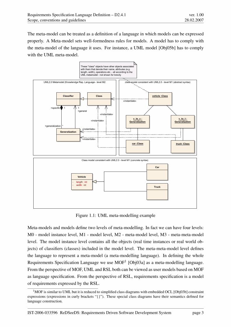
The meta-model can be treated as a definition of a language in which models can be expressedproperly. A Meta-model sets well-formedness rules for models. A model has to comply withthe meta-model of the language it uses. For instance, a UML model [Obj05b] has to complywith the UML meta-model.
Class model consistent with UML2.0 - level M1 (concrete syntax)
class model consistent with UML2.0 - level M1 (abstract syntax)UML2.0 Metamodel (Knowlendge Rep. Language - level M2
Classifier Class
Generalization
vehicle :Class
car :Class truck :Class
v_to_c :
Generalization
v_to_t :
Generalization
Vehicle
- length: int
- width: int
Car
Truck
These "class" objects have other objects associated
with them that denote their name, attributes (e.g.
length, width), operations etc. - all according to the
UML metamodel - not shown for brevity
«instantiate»
«instantiate»
«instantiate»
«instantiate»
«instantiate»
+general
1
+generalization *
+specific 1
Figure 1.1: UML meta-modelling example
Meta-models and models define two levels of meta-modelling. In fact we can have four levels:M0 - model instance level, M1 - model level, M2 - meta-model level, M3 - meta-meta-modellevel. The model instance level contains all the objects (real time instances or real world ob-jects) of classifiers (classes) included in the model level. The meta-meta-model level definesthe language to represent a meta-model (a meta-modelling language). In defining the wholeRequirements Specification Language we use MOF1 [Obj03a] as a meta-modelling language.From the perspective of MOF, UML and RSL both can be viewed as user models based on MOFas language specification. From the perspective of RSL, requirements specification is a modelof requirements expressed by the RSL.
1MOF is similar to UML but it is reduced to simplified class diagrams with embedded OCL [Obj03b] constraintexpressions (expressions in curly brackets “{}”). These special class diagrams have their semantics defined forlanguage construction.
IST-2006-033596 ReDSeeDS: Requirements Driven Software Development System page 3
Requirements Specification Language Definition – D2.4.1Scope, conventions and guidelines
ver. 1.0028.02.2007
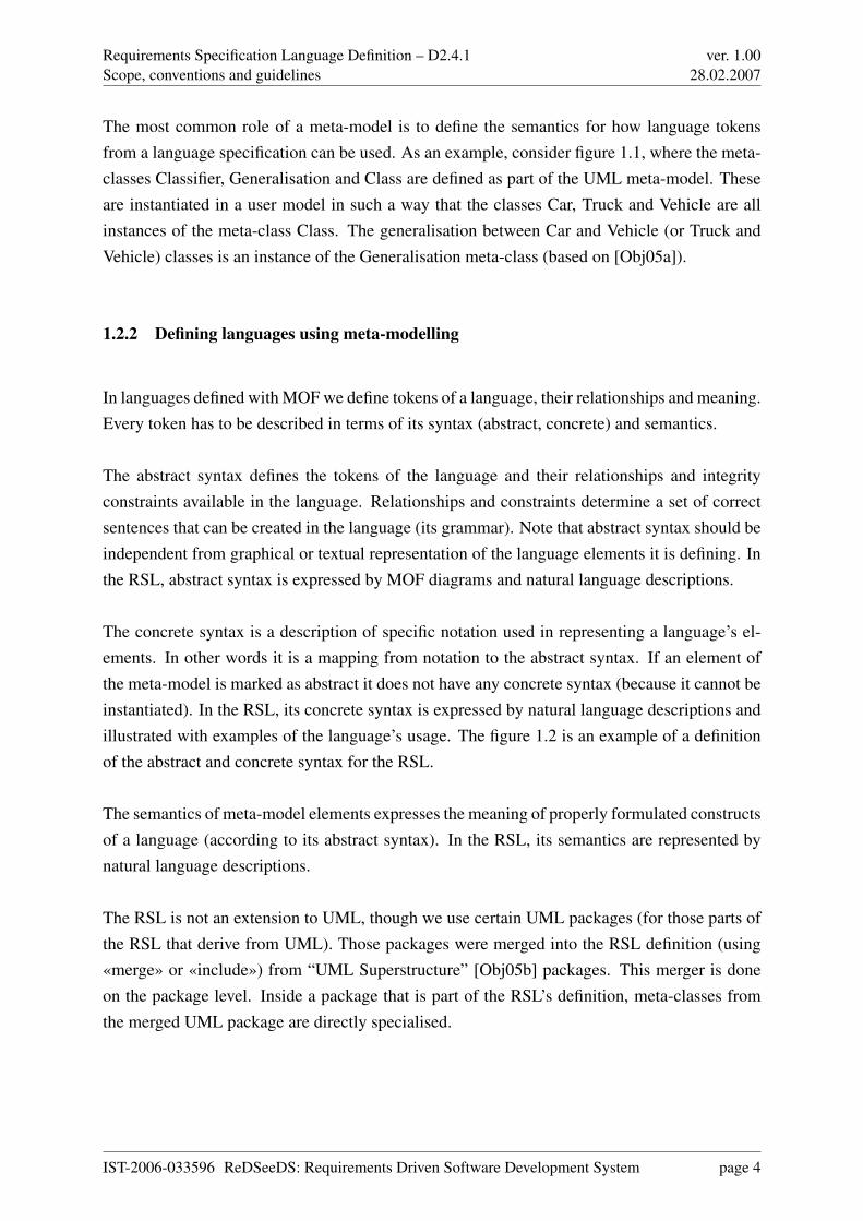
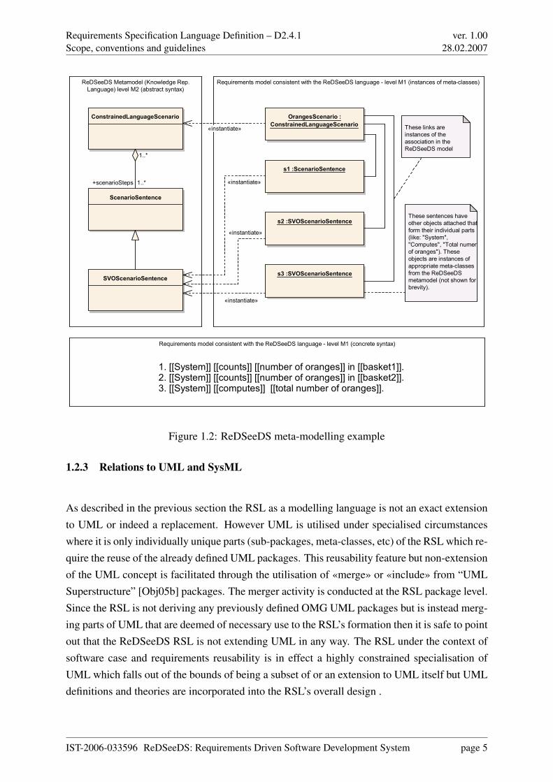
The most common role of a meta-model is to define the semantics for how language tokensfrom a language specification can be used. As an example, consider figure 1.1, where the meta-classes Classifier, Generalisation and Class are defined as part of the UML meta-model. Theseare instantiated in a user model in such a way that the classes Car, Truck and Vehicle are allinstances of the meta-class Class. The generalisation between Car and Vehicle (or Truck andVehicle) classes is an instance of the Generalisation meta-class (based on [Obj05a]).
1.2.2 Defining languages using meta-modelling
In languages defined with MOF we define tokens of a language, their relationships and meaning.Every token has to be described in terms of its syntax (abstract, concrete) and semantics.
The abstract syntax defines the tokens of the language and their relationships and integrityconstraints available in the language. Relationships and constraints determine a set of correctsentences that can be created in the language (its grammar). Note that abstract syntax should beindependent from graphical or textual representation of the language elements it is defining. Inthe RSL, abstract syntax is expressed by MOF diagrams and natural language descriptions.
The concrete syntax is a description of specific notation used in representing a language’s el-ements. In other words it is a mapping from notation to the abstract syntax. If an element ofthe meta-model is marked as abstract it does not have any concrete syntax (because it cannot beinstantiated). In the RSL, its concrete syntax is expressed by natural language descriptions andillustrated with examples of the language’s usage. The figure 1.2 is an example of a definitionof the abstract and concrete syntax for the RSL.
The semantics of meta-model elements expresses the meaning of properly formulated constructsof a language (according to its abstract syntax). In the RSL, its semantics are represented bynatural language descriptions.
The RSL is not an extension to UML, though we use certain UML packages (for those parts ofthe RSL that derive from UML). Those packages were merged into the RSL definition (using«merge» or «include») from “UML Superstructure” [Obj05b] packages. This merger is doneon the package level. Inside a package that is part of the RSL’s definition, meta-classes fromthe merged UML package are directly specialised.
IST-2006-033596 ReDSeeDS: Requirements Driven Software Development System page 4
Requirements Specification Language Definition – D2.4.1Scope, conventions and guidelines
ver. 1.0028.02.2007
Requirements model consistent with the ReDSeeDS language - level M1 (concrete syntax)
Requirements model consistent with the ReDSeeDS language - level M1 (instances of meta-classes)ReDSeeDS Metamodel (Knowledge Rep.
Language) level M2 (abstract syntax)
ConstrainedLanguageScenario
ScenarioSentence
SVOScenarioSentence
OrangesScenario :
ConstrainedLanguageScenario
s1 :ScenarioSentence
s2 :SVOScenarioSentence
s3 :SVOScenarioSentence
These links are
instances of the
association in the
ReDSeeDS model
These sentences have
other objects attached that
form their individual parts
(like: "System",
"Computes", "Total numer
of oranges"). These
objects are instances of
appropriate meta-classes
from the ReDSeeDS
metamodel (not shown for
brevity).
1. [[System]] [[counts]] [[number of oranges]] in [[basket1]].2. [[System]] [[counts]] [[number of oranges]] in [[basket2]].3. [[System]] [[computes]] [[total number of oranges]].
+scenarioSteps 1..*
1..*
«instantiate»
«instantiate»
«instantiate»
«instantiate»
Figure 1.2: ReDSeeDS meta-modelling example
1.2.3 Relations to UML and SysML
As described in the previous section the RSL as a modelling language is not an exact extensionto UML or indeed a replacement. However UML is utilised under specialised circumstanceswhere it is only individually unique parts (sub-packages, meta-classes, etc) of the RSL which re-quire the reuse of the already defined UML packages. This reusability feature but non-extensionof the UML concept is facilitated through the utilisation of «merge» or «include» from “UMLSuperstructure” [Obj05b] packages. The merger activity is conducted at the RSL package level.Since the RSL is not deriving any previously defined OMG UML packages but is instead merg-ing parts of UML that are deemed of necessary use to the RSL’s formation then it is safe to pointout that the ReDSeeDS RSL is not extending UML in any way. The RSL under the context ofsoftware case and requirements reusability is in effect a highly constrained specialisation ofUML which falls out of the bounds of being a subset of or an extension to UML itself but UMLdefinitions and theories are incorporated into the RSL’s overall design .
IST-2006-033596 ReDSeeDS: Requirements Driven Software Development System page 5
Requirements Specification Language Definition – D2.4.1Scope, conventions and guidelines
ver. 1.0028.02.2007
In contrast, SysML [Obj06b] as a domain specific modelling language was purposefully createdas an open source project to aid in supporting the specification, analysis, design, verificationand validation of an ever broadening range of systems and systems of systems which are notsoftware centric or indeed software oriented in any way. See http://www.sysml.org/. SysML isdefined to be an extension to a subset of UML using the UML profiling mechanism. This allowsfor robust modelling to be conducted within the generalised field of systems engineering. Assuch SysML is an enhancement to UML which takes away some of UML’s software centricspecialisation features and replaces them with generality or generic features special to the entireengineering field as a whole.
One extension of SysML of potential interest for our RSL is a part explicitly dedicated to re-quirements in textual form. We even considered to base RSL on this part of SysML. However,what is defined there only covers a minor part of what we can express for requirements. Inparticular, there is no classification of requirements, and they can be related only in predefinedways. So, the reuse effect would have been very small.
While it was intended by the developers of SysML to keep this part small and to rather have itextended, such extensions would have been very laborious, if not also very hard to do for ev-erything we had in mind. In particular, the textual representation of a requirement is inherentlymixed up with the corresponding requirements entity itself. In contrast, we strive for a cleandistinction between requirements and their representation.
Considering the view of SysML as now defined it is plausible to say that the ReDSeeDS RSL isintended to be similar to SysML’s portrayal in that the RSL is effectively to become the SysMLfor software centric requirements reuse but without the need to extend UML or any subsets ofUML.
1.2.4 Structure of the language reference
Part II of this document contains the RSL definition. It has been divided into sections accordingto the logical structure of packages and subpackages of the RSL.
The RSL is divided into five main packages:
• Kernel (abstract elements of the language forming the common basis for other elements)
• Requirements (requirements as such with their relationships)
IST-2006-033596 ReDSeeDS: Requirements Driven Software Development System page 6
Requirements Specification Language Definition – D2.4.1Scope, conventions and guidelines
ver. 1.0028.02.2007
• Requirements Representations (definitions of individual requirements in various nota-tions)
• Requirement Representation Sentences (basic “building blocks”, i.e. sentences that formthe representations as above)
• Domain elements (elements that allow for forming a vocabulary of phrases based oncommon terminology)
Each of theses packages is described briefly with an overview section (including a packagediagram), which is followed by description of its subpackages. Every subpackage is presented inan overview explaining general ideas behind a package, a meta-model diagram for this packageand two sections which describe the abstract syntax with semantics of language constructs andthe concrete syntax.
1.2.5 Notation conventions
Lowest level package descriptions use the following notation conventions:
• sans-serif font is used for names of classes, attributes and associations, e.g. Requirement
• if a class name is used in description of package other than the one it is included in, itis preceded with package name and a double colon (“::”), e.g. RequirementsSpecifica-
tions::Requirement
• bold/italics font is used for emphasized text, e.g. Abstract syntax
Class colours used on the diagrams indicate membership of the packages. Introduction ofcolours is intended to enhance readability of diagrams which contain classes from differentpackages (e.g. blue colour denotes that classes are from Requirement packages, yellow arefrom RequirementRepresentation package and green are from DomainElement package).
1.3 Related work and relations to other documents
External research work conducted in compliance with formulating a good understanding ofthe Requirements Specification Language included researching and reasoning about such ar-
IST-2006-033596 ReDSeeDS: Requirements Driven Software Development System page 7
Requirements Specification Language Definition – D2.4.1Scope, conventions and guidelines
ver. 1.0028.02.2007
eas as software case representations, query procedure pragmatics, Domain representation, Do-main mapping with or without hyperlinking, Domain access methods via taxonomies and sim-ilarity measures concerning domain constructs (vocabulary items) and requirement dependen-cies/interdependencies leading to possible upgrades of the domain or industry specific termi-nology including terms.
From the domain elements part of RSL, a means for modelling domain entities are introduced,such as domain entity types, vocabulary, phrases, and terms. Terms are organised in a terminol-ogy. Domain entities are used for representing requirements of each new software developmentproject forming a requirement model of the developed software case. For performing case re-trieval on the basis of similarity measures, this requirement model is mapped and included in aso-called software knowledge model. This software knowledge model contains the knowledgeknown for all software cases of an organisation i.e. the software vendor that implements thedifferent software cases.
For reuse purposes, we strive in this project for finding software cases based on similarity mea-sures. In principle, this can be done by text-based approaches, where our terminology as definedin the language will be very useful. For including more semantics into similarity measures, anontology of the given application domain should be available. While our requirements languagedoes not yet include any means for knowledge representation and reasoning, the user may stilluse it to represent a domain model using object-oriented means (in the form of a domain ele-ment diagram, as derived from a UML class diagram). Such models can be used as a simpleform of ontology. These issues will be worked out in Workpackages 3 and 4 of ReDSeeDS anddiscussed in the related deliverables.
One form of representing requirements in ReDSeeDS is to write them down in constrainedlanguage. This constrained language uses the so-called SVO(O)-Grammar, recently researchedat WUT [SBNS05b, SBNS05a]. Other significant work concerning some kind of restrictionto natural language was and is still done in the Attempto research project conducted by theDepartment of Informatics and the Institute of Computational Linguistics at the University ofZurich [FHK+05].
The Attempto Controlled English (ACE) language developed in the course of the Attempto
project is currently available in its fifth version. Although ACE closely resembles natural En-glish, the syntax of a text written in ACE is based on a defined abstract grammar which avoidsambiguity in language constructs [Hoe04]2. Furthermore, ACE can be automatically translatedinto first-order logic and consequently be read by humans as well as by machines.
2The cited article contains abstract grammar for ACE 4.0. The grammar for version 5.0 has not been publishedyet.
IST-2006-033596 ReDSeeDS: Requirements Driven Software Development System page 8
Requirements Specification Language Definition – D2.4.1Scope, conventions and guidelines
ver. 1.0028.02.2007
The results of search engines in the internet for "user interface" is a long list including confer-ences, workshops, symposia etc. This incudes conferences like the International Conference onIntelligent User Interfaces (IUI), Computer Human Interaction (CHI), International Conferenceon HumanComputer Interaction (INTERACT), The International Conference on UbiquitousComputing (UbiComp) etc. They all show a number of on going research activities in this field.A short analysis of these activities will show that most research is concerned with the designof user interfaces as one stage in the software development process, and not with the elicita-tion of user interface requirements in the analysis phase. Consequently, re-use of user interfacerequirements becomes impossible. Nevertheless significant research work in the field of userinterface development that serve as a basis for the RSL has been done.
1.3.1 Model Based User Interface Development
Following the Model Based User Interface Development (MB-UID), the user interface is spec-ified through different declarative models at different abstraction levels (see [Sze96])
• at the highest abstraction level is the application model. This defines the objects in thedomain as well as the user tasks. Some of these objects can be manipulated by users onthe user interface.
• at the following abstraction level is the abstract user interface specification. Abstractinteraction objects (AIO) are defined at this level. they include groups of objects forinformation representation as well as for the user interaction and the dialog.
• at the third level the concrete user interface is defined by using concrete interaction objects(CIO). These are concrete objects, e.g., button, window, checkbox, text field etc., fromthe object library of a selected toolkit.
Other models include the user model and the platform model (see Figure 1.3).
The distribution of user interface aspects over several models allows the separation of concerns,an important requirement especially for complex user interfaces. An extensive overview ofMB-UID can be found in [Mol04].
IST-2006-033596 ReDSeeDS: Requirements Driven Software Development System page 9

Requirements Specification Language Definition – D2.4.1Scope, conventions and guidelines
ver. 1.0028.02.2007
Figure 1.3: The MB-UID Architecture
1.3.2 User Interface Description Languages
Since the existence of XML as a universal data format, several languages for the descriptionof user interfaces models (UIDL) for predefined systems have been developed. They can beclassified according to
1. The abstraction levels of their elements with respect to the elements of the implementationtoolkit,
2. Their application domains and
3. The abstraction levels of the resulting models with respect to modality.
The first category includes UIDLs with abstract elements like UIML [AH02] and those thatprovide concrete elements like XUL [Moz02].In the second category, there are general purpose UIDLs, e.g., UIML [AH02], and those forspecific application domains, e.g., XUL [Moz02] for web applications.The third category includes UIDLs following on the approach of first defining the abstractuser interface with modality independent elements and then transforming the resulting descrip-tion into a concrete user interface by providing modality dependent elements, e.g., UsIXML[Lim04], or integrating modality specific elements of different modalities in one model, e.g,
IST-2006-033596 ReDSeeDS: Requirements Driven Software Development System page 10
Requirements Specification Language Definition – D2.4.1Scope, conventions and guidelines
ver. 1.0028.02.2007
useGUI [Muk06]. An extensive survey of most UIDLs can be found in [Lim04].As mentioned previously, the goal of these UDLs is to support the design phase of the softwaredevelopment process. In the contrary, the UI descriptive part of the RSL should support theanalysis phase.
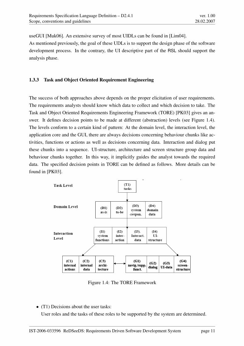
1.3.3 Task and Object Oriented Requirement Engineering
The success of both approaches above depends on the proper elicitation of user requirements.The requirements analysts should know which data to collect and which decision to take. TheTask and Object Oriented Requirements Engineering Framework (TORE) [PK03] gives an an-swer. It defines decision points to be made at different (abstraction) levels (see Figure 1.4).The levels conform to a certain kind of pattern: At the domain level, the interaction level, theapplication core and the GUI, there are always decisions concerning behaviour chunks like ac-tivities, functions or actions as well as decisions concerning data. Interaction and dialog putthese chunks into a sequence. UI-structure, architecture and screen structure group data andbehaviour chunks together. In this way, it implicitly guides the analyst towards the requireddata. The specified decision points in TORE can be defined as follows. More details can befound in [PK03].
Figure 1.4: The TORE Framework
• (T1) Decisions about the user tasks:User roles and the tasks of these roles to be supported by the system are determined.
IST-2006-033596 ReDSeeDS: Requirements Driven Software Development System page 11
Requirements Specification Language Definition – D2.4.1Scope, conventions and guidelines
ver. 1.0028.02.2007
• (D1) Decisions about the as-is activities:Decision on which activities users currently perform and whether these are relevant forthe system. The activities are derived from the tasks. Hence user tasks are being refinedhere.
• (D2) Decisions about the to-be activities:Decision on new tasks as the improvement of the as-is activities.
• (D3) Decisions about the system responsibilities:Which activities should be done automatically by the system and which should be left tothe user?
• (D4) Decisions about the domain data relevant for a task:System responsibilities of UIS manipulate data. Decisions have to be made on whichdomain data are relevant for the system responsibilities.
• (I1) Decisions about the system functions:System responsibilities are realised by system functions. The decision about the systemfunctions determines the border between user and system.
• (I2) Decisions about user-system interaction:It has to be decided how the user can use the system function to achieve the systemresponsibilities. This determines the interaction between user and system.
• (I3) Decisions about interaction data:For each system function the input data provided by the user as well as the output dataprovided by the system have to be defined.
• (I4) Decisions about the structure of the user interface (UI-structure): Decisions about thegrouping of data and system functions in different workspaces have to be made. Throughthe UI-structure, the rough architecture of the user interface is defined. This structure hasa big influence on the usability of the system.
• (C1) Decisions about the application architecture:The code realising the system functions is modularised into different components. In thedecision about the component architecture, existing components and physical constraintsas well as quality constraints such as performance have to be taken into account. Only apreliminary decision concerning the architecture is made during requirements.
• (C2) Decisions about the internal system actions:Decisions have to be made regarding the internal system actions that realise the systemfunctions. The system actions define the effects of the system function on the data.
IST-2006-033596 ReDSeeDS: Requirements Driven Software Development System page 12
Requirements Specification Language Definition – D2.4.1Scope, conventions and guidelines
ver. 1.0028.02.2007
• (C3) Decisions about internal system data:The internal system data refines the interaction data to the granularity of the system ac-tions. The decisions about the internal system data reflect all system actions. In OO,system data is grouped within classes.
• (G1) Decisions about navigation and support functions:It has to be decided how the user can navigate between different screens during the exe-cution of system functions. This determines the navigation functions.
• (G2) Decisions about dialog interaction:For each interaction the detailed control of the user has to be decided. This determinesthe dialog. It consists of a sequence of support and navigation function executions. Thesedecisions also have a strong influence on the usability of the system.
• (G3) Decisions about detailed UI-data:For each navigation and support function, the input data provided by the user as well asthe output data provided by the system have to be defined. These decisions determine theUI-data visible on each screen.
• (G4) Decisions about screen structure:The separation of workspaces as defined in (I4) into different screens that support thedetailed dialog interaction as described in (G2) has to be decided. The screen structuregroups navigation and support functions as well as UI-data. The decisions to separate theworkspaces into different screens are influenced by the platform of the system.
1.4 Structure of this Document
Part I gives a conceptual overview of the behavioural, structural and user interface parts ofthe Requirements Specification Language. The behavioural part introduces the requirementslanguage and the representation language and deals with functional and behavioural require-ments and presents their conceptual model. Then outlined are possible representations of therequirements without going too deeply into detail. Newly introduced concepts affecting thebehavioural aspects are also discussed. The structural part of RSL gives a conceptual overviewof domain entities and dictionaries. It describes different types of entities existing in a domainand the conceptual model of the domain’s vocabulary, respectively. the user interface part com-municates the purpose of modelling user interfaces within requirements specifications, containsa rationale and outlines the approach taken in development of this part of the language. Alsodescribed are the basics of modelling elements and behaviour within the user interface environ-ment.
IST-2006-033596 ReDSeeDS: Requirements Driven Software Development System page 13
Requirements Specification Language Definition – D2.4.1Scope, conventions and guidelines
ver. 1.0028.02.2007
Part II initially defines the metamodel of the RSL’s behavioural part, again dealing with thesubject of requirements itself and different possibilities for requirement representation. It isdivided into four chapters, each of them dealing with a part of the metamodel. Every chapterhas a short overview, defines abstract syntax and semantics and then gives a short example of theconcrete syntax. It defines the part of the metamodel containing the requirements themselvesand their arrangement. It explains the part of the metamodel that deals with different kindsof representations, especially textual representations and schematic representations, which canbe displayed as UML-like models. It then defines the grammar for the semi-formal textualrepresentation.
Furthermore part II, after discussing the benefits and consequences of using a domain vocabu-lary, defines the domain elements (structural) part of the language. This major package containsseveral subpackages. These subpackages cover basic domain entities, the actors in the system’senvironment and the representations of the system and the entities. Furthermore, this packagecontains phrases and other, more fine-grained elements which compose phrases. Phrases consti-tute the names of the entities as well as the parts of a sentence in constrained language. Finally,the package comprises the individual terms which can occur in a phrase. Each section con-cerning one of the packages has an overview, defines abstract syntax and semantics, and thengives a short explanation of the concrete syntax using the Fitness Club case study as a runningexample.
Finally, partII specifies the meta-model for the user interface aspects of the Requirements Spec-ification Language. Here, there are addressed the structural and behavioural aspects of UIspecification on the requirements level.
1.5 Usage guidelines
The ReDSeeDS Requirements Specification Language (RSL) definition should be used as abook that guides the reader through the structure, syntax and semantics definitions of the RSL,as part of the complete ReDSeeDS Software Case Specification Language (to be defined inWorkpackage 3). It should be used mainly by creators of appropriate software CASE tools(with reusability features) that would allow handling of the language by the end users (analysts,etc.) to express behaviour of the system under development. It can be used by advanced endusers of the language as a reference for the language’s syntax and semantics. Examples of RSLelements’ concrete syntax have illustrative character and should be treated only as support inunderstanding of a given element’s occurrence.
IST-2006-033596 ReDSeeDS: Requirements Driven Software Development System page 14
Requirements Specification Language Definition – D2.4.1Scope, conventions and guidelines
ver. 1.0028.02.2007
Users of the RSL Specification are expected to know the basics of metamodelling and MOF(Meta Object Facility) specification [Obj06a]. Knowledge of UML ([Obj05b] and [Obj05a])could be helpful as some elements of RSL are extensions, constraints or redefinitions of UMLelements.
IST-2006-033596 ReDSeeDS: Requirements Driven Software Development System page 15
Requirements Specification Language Definition – D2.4.1 ver. 1.0028.02.2007
Part I
Conceptual Overview of the CoherentRequirements Language
IST-2006-033596 ReDSeeDS: Requirements Driven Software Development System page 16
Requirements Specification Language Definition – D2.4.1Introduction
ver. 1.0028.02.2007
Chapter 2
Introduction
The ReDSeeDS Requirements Specification Language (meta-)model consists of 3 parts, whichare linked to an extra model of the Reuse Domain:
1. Requirements Language
2. Requirements Representation Language
3. Application Domain Language
The primary reason for separation of the overall language model into several parts is the sepa-ration of concerns. In particular, the main separation is between Requirements Language andRequirements Representation Language. This is a crucial innovation, which is important sincewe are not reusing requirements themselves but rather requirements representations.
The separation of Requirements Language and Requirements Representation Language allowsseparation and simplification of the Reuse Domain. Avoiding the separation between the formertwo would force integration of the latter and mixing of the different concerns and lead to highercomplexity of the overall language specification. In addition, requirements are not reusabledirectly, and this fact should be reflected in the language specification.
It is also important that the representation of the Application Domain is distinct from the Re-quirements Representation, while they will be linked, of course. The requirements may notbe understood without the links to the Application Domain, but the content of the applicationdomain is not requirements.
IST-2006-033596 ReDSeeDS: Requirements Driven Software Development System page 17
Requirements Specification Language Definition – D2.4.1Introduction
ver. 1.0028.02.2007
Hyperlinks between Application Domain and Requirement Representation are a crucial elementof our language, and greatly facilitate keeping the specification coherent.
IST-2006-033596 ReDSeeDS: Requirements Driven Software Development System page 18
Requirements Specification Language Definition – D2.4.1Requirements for the requirements language
ver. 1.0028.02.2007
Chapter 3
Requirements for the requirementslanguage
Before actually designing our requirements language RSL as a joint effort of several partners, itwas deemed useful to gather requirements for RSL itself. Unfortunately, RSL has obviously notyet been available for specifying its own requirements. So, we simply used natural language fortheir representation. Still, we used the keywords shall and should (in italics) for clearly distin-guishing mandatory from optional requirements. We also separated functional from constraintrequirements. The sections below list the results of this informal requirements acquisition.
3.1 Functional Requirements
• RSL shall allow describing any kind of requirement in (free) natural language text.
• RSL shall allow assigning a unique identifier to each requirement, which becomes a re-quirement entity in this way.
• RSL shall allow specifying whether a requirement is mandatory or optional.
• RSL shall allow including attributes to each requirement entity.
• RSL shall allow to formulate scenarios in textual form according to a given grammar.
• RSL shall allow to formulate use cases and to link scenarios to them.
• RSL shall allow to explicitly link a scenario with functional requirements for the systemto be built in such a way, as to specify which functions will have to be available to executethis scenario.
IST-2006-033596 ReDSeeDS: Requirements Driven Software Development System page 19
Requirements Specification Language Definition – D2.4.1Requirements for the requirements language
ver. 1.0028.02.2007
• RSL shall allow defining a glossary of terms in natural language, which serves as a de-fined vocabulary for formulating the requirements.
• RSL shall allow to model requirements using a selection of UML 2.0 diagrams.
• RSL shall allow building hierarchical structures of the requirements entities.
• RSL shall allow cross-linking of the requirements entities.
• RSL should allow linking each entry of the glossary of terms with a corresponding classin UML diagrams.
• RSL shall allow defining a user interface of the system to be built.
• RSL should allow specifying a task model.
• RSL should allow linking to any kind of descriptions or models in any other language.
• RSL should allow defining stakeholders.
3.2 Constraint Requirements
• RSL shall have a mandatory core part that is being used for finding similar cases.
• RSL shall have optional parts that are not being used for finding similar cases.
• RSL shall be defined based on the UML 2.0 metamodel, both through restrictions andextensions.
• RSL shall have compatible representations of requirements and user interface.
• RSL documents shall be semi-formal in the sense of including both formal and informalrepresentation.
• RSL should be extensible.
IST-2006-033596 ReDSeeDS: Requirements Driven Software Development System page 20
Requirements Specification Language Definition – D2.4.1Requirements Model
ver. 1.0028.02.2007
Chapter 4
Requirements Model
Requirements engineering (RE) is the essential activity in assuring that one builds computer-based systems that will satisfy stakeholders’ goals. As the need for a systematic method ofrequirements elicitation and specification first became obvious for very large and complex sys-tems, most RE research focused on discovery and development of requirements techniques andartefacts that are tailored to support the development of these very large systems in those en-vironments with relatively large amounts of resources. Developers of a small system, on theother hand, traditionally used an ad hoc approach to RE due to the system’s small size andthe developers’ unsystematic approach to development. The importance of systematic RE in-creases dramatically, even for small systems, with the introduction of product-line approaches,customisable software, etc. So, over time, we have gone from ad hoc approaches to require-ments management to more formal ways of capturing and managing requirements. This trendis what led to our project and the goal of building systems based on requirements reuse. That is,if we are systematically capturing and managing requirements for one project then we shouldbe able to reuse some of these requirements on other similar projects.
The other important impact on RE techniques is due to the nature of the development of largesystems. Traditionally, a typical Computer-Based System (CBS) is developed in-house, wheredevelopers work with relatively stable domains, are responsible for the development of the sys-tem from scratch, and have relatively stable production teams and a large amount of resources.This way of development has led to the dominance of the requirements specification that focusesmainly on product-level requirements such as features [Lau02] and subsequently on low-levelrequirements and design. Designs of different systems have already been successfully reusedeither through reuse such as using design pattern or through larger scale reuse such as using ref-erence architectures for the specification of the new systems. The reuse of these design elementsimplied the reuse of some of the background requirements that led to these designs, but there
IST-2006-033596 ReDSeeDS: Requirements Driven Software Development System page 21
Requirements Specification Language Definition – D2.4.1Requirements Model
ver. 1.0028.02.2007
was no intentional and systematic reuse of the requirements as such. The main contribution ofthis project will be in pushing the reuse effort even further, i.e., beyond design reuse — all theway to systematic requirement reuse. The primary target, for facilitating reuse are product-leveland low-level requirements.
Product-level and low-level requirements are very well studied and widely applied in industrialsettings, but the main difficulty is in ensuring that they fulfil essential business goals. Product-level requirements form a set of features that, combined, are used to achieve the organisation’sbusiness goals. The success of the overall goal depends on every single one of the features andon the particularities of their interactions. The problem of achieving goals is exacerbated as aresult of their frequent changes over time, which cause a chain reaction of changes in product-level and low-level requirements.
Lauesen has observed that product-level and low-level requirements management is straightfor-ward and changes to them are relatively easy to deal with in practice [Lau02]. Developers canusually sense when these requirements are not correct and do not fit with each other. This abilityusually does not work at the higher levels of abstractions, and it is the responsibility of the busi-ness analyst to deal with these higher level requirements. In an occasional case, it is not evenpossible to estimate how changes in the product-level requirements effect overall goals untilthe changes are implemented [Lau02]. Therefore, besides attempting to reuse product-level andlow-level requirements, our project is also dealing with the reuse of higher-level requirementsin order to ensure the traceability and the fulfilment of all the requirements at the later designstages for the system that is built through the requirements reuse.
Requirements are specified either directly or indirectly for many different purposes and as partof many different engineering activities. One example classification is [Lau02]:
1. Business-level requirements specification — Business-level requirements are most oftenspecified indirectly as part of business re-engineering activities. The most common con-cepts that appear at this level are business goals, processes, resources, and rules. Forexample, for an elevator system, a business-level requirement is: “The elevator shalltransport passengers and goods from any floor to any other floor.”
2. Domain-level requirements specification — Domain-level requirements, as mentionedpreviously, are most often indirectly specified in the traditional requirements specifica-tions [DvLF93]. Newer, more systematic versions of domain-level RE have received a lotof attention recently [BPG+01, CKM01, MCL+01]. Most explicit domain-level require-ments are captured and specified for domains, which are becoming increasingly complexand difficult to adequately support by systems [CKM02, GMP01, GPS01, MC00]. The
IST-2006-033596 ReDSeeDS: Requirements Driven Software Development System page 22
Requirements Specification Language Definition – D2.4.1Requirements Model
ver. 1.0028.02.2007
most common concepts that appear at this specification level are user goals, user tasks,domain input, and domain output. A more recent trend is the incorporation of agent-basedanalysis as part of domain modelling [MKG02, KGM02, MKC01, GPM+01]. For an el-evator system, an example domain-level requirement is: “The elevator shall be accessiblefrom each floor.”
3. Product-level requirements specification — Product-level requirement specifications arethe most common type of requirement specifications. There is an extensive body ofknowledge about them, and most previous research focused on improving the differenttechniques used to elicit, specify, and validate this type of requirement. The commonartefacts and concepts that occur as parts of product-level specifications are features, usecases, functional lists, data input, data output, etc. For an elevator system, an exampleproduct-level requirement is: “The elevator shall accept elevator calls only while station-ary.”
4. Design-level requirements specification — Design-level requirements specification arethe requirements that directly constrain the design of a system. Much effort has beeninvested into its standardisation through the Unified Modelling Language (UML) [Lar04,Fow04]. UML artefacts and underlying techniques present the most common types ofconcepts and techniques used to capture requirements at this level. This level acts as atransition phase between product-level specification and code-level requirement specifi-cations. For an elevator system, an example design-level requirement is: “A queue datastructure shall be used to store the data for elevator calls.”
5. Code-level requirements specification — Code-level requirements are usually specifiedas part of the programming activity and describe details of low-level algorithm and datastructures. This type of specification is that with which most programmers are familiar, asit is inseparable from coding. Code-level requirements focus mainly on implementation-related issues and constraints and are probably the best understood form of requirementsspecification. For an elevator system, an example code-level requirement is: “Due to thetiming constraints, function calls to retrieve elevator call data shall be implemented in theC programming language rather than in the Python programming language.”
This work and our requirements language is applicable and can be used at all these requirementand requirement specification levels in order to ensure full reuse and proper development of thenew system.
IST-2006-033596 ReDSeeDS: Requirements Driven Software Development System page 23
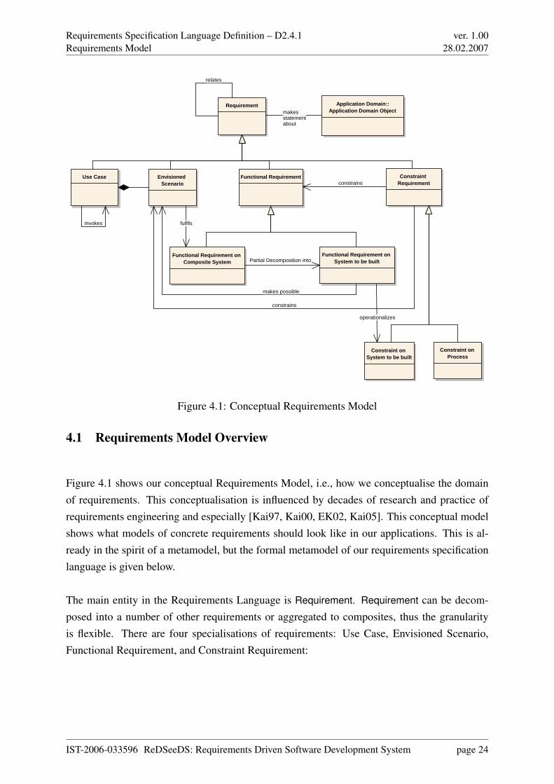
Requirements Specification Language Definition – D2.4.1Requirements Model
ver. 1.0028.02.2007
Application Domain::Application Domain Object
Requirement
Use Case Envisioned Scenario
Functional Requirement Constraint Requirement
Functional Requirement on Composite System
Functional Requirement on System to be built
Constraint on Process
Constraint on System to be built
makes possible
constrains
Partial Decomposition into
constrains
invokes
relates
makesstatementabout
fulfils
operationalizes
Figure 4.1: Conceptual Requirements Model
4.1 Requirements Model Overview
Figure 4.1 shows our conceptual Requirements Model, i.e., how we conceptualise the domainof requirements. This conceptualisation is influenced by decades of research and practice ofrequirements engineering and especially [Kai97, Kai00, EK02, Kai05]. This conceptual modelshows what models of concrete requirements should look like in our applications. This is al-ready in the spirit of a metamodel, but the formal metamodel of our requirements specificationlanguage is given below.
The main entity in the Requirements Language is Requirement. Requirement can be decom-posed into a number of other requirements or aggregated to composites, thus the granularityis flexible. There are four specialisations of requirements: Use Case, Envisioned Scenario,Functional Requirement, and Constraint Requirement:
IST-2006-033596 ReDSeeDS: Requirements Driven Software Development System page 24

Requirements Specification Language Definition – D2.4.1Requirements Model
ver. 1.0028.02.2007
• A Use Case consists of a number of Envisioned Scenarios that belong together in termsof use. E.g., the Use Case for getting cash money has several scenarios of how this isactually envisioned to be achieved.
• Envisioned Scenarios are the means of achieving high-level functions given as FunctionalRequirements on Composite System (e.g., Cash Withdrawal). The composite systemincludes the system to be built (e.g., an ATM) and possibly other systems (e.g., a banksystem), including human users (e.g., bank customers).
• Functional Requirements are the generalisation of Functional Requirements on Compos-ite System and Functional Requirement on System to be built. The latter are functionsneeded (e.g., Customer Identification or Cash Provision) that will make possible the en-actment of Envisioned Scenarios once available. In effect, Functional Requirements onComposite System are partially decomposed into Functional Requirements on System tobe built.
• Functional Requirements are tightly related to Constraint Requirements. Constraint Re-quirements often constrain Functional Requirements. E.g., only solutions for Cash Provi-sion are acceptable (in the overall solution space) that are secure and reliable. There aretwo specialisations of Constraint Requirements: Constraint on Process and Constraint onSystem to be built. The former involve, for instance, development method or tools, thelatter, for instance, security or reliability. Some Functional Requirements on System tobe built operationalize Constraint Requirements on System to be built. E.g., (required)functions for accepting a password, etc. operationalize a security requirement.
4.2 Requirements Model Details
Requirement
IEEE Std 610.12-1990: IEEE Standard Glossary of Software Engineering Terminology definesrequirement as:
1. A condition or capability needed by a user to solve a problem or achieve an objective.
2. A condition or capability that must be met or possessed by a system or system componentto satisfy a contract, standard, specification, or other formally imposed documents.
3. A documented representation of a condition or capability as in (1) or (2).
IST-2006-033596 ReDSeeDS: Requirements Driven Software Development System page 25
Requirements Specification Language Definition – D2.4.1Requirements Model
ver. 1.0028.02.2007
As discussed previously, a requirement can exist at multiple abstraction levels. It is commonto decompose higher-level requirements to lower-level requirements forming some kind of re-quirement decomposition tree. Each requirement is typically related to a number of other re-quirements. In addition, each requirement can be represented in multiple views. As such, wehave a number of dimensions that constrain and make it challenging to capture a requirementproperly with all its relationships.
This difficulty was obvious even during our work. It was hard to boil down and to keep in mindthe clear definition of what a requirement is. This was particularly difficult when discussingdifferent types of requirements. Any deviation from the common definition resulted in a rippleeffect of conflicts with other terms and definitions of other language constructs. This is why weinsisted on strictly following and not modifying the standard definition of what a requirement isin the early stages of our work. Nevertheless, at the end we had to adapt and limit this definitionas discussed in the Discussion section.
Use Case
The official definition for use cases in our project is:
“A collection of possible scenarios between the system under discussion and ex-ternal actors, characterised by the goal the primary actor has toward the system’sdeclared responsibilities, showing how the primary actor’s goal might be deliveredor might fail.” [Coc97]
Use cases are related using invoke relationship. This relationship unifies and overrides thestandard UML use case relationships extends and includes.
Envisioned Scenario
The definition for a scenario in our project is:
“A sequence of interactions happening under certain conditions, to achieve the pri-mary actor’s goal, and having a particular result with respect to that goal. The
IST-2006-033596 ReDSeeDS: Requirements Driven Software Development System page 26
Requirements Specification Language Definition – D2.4.1Requirements Model
ver. 1.0028.02.2007
interactions start from the triggering action and continue until the goal is deliv-ered or abandoned, and the system completes whatever responsibilities it has withrespect to the interaction.” [Coc97]
Of course, not every scenario may be considered a requirement. In particular, an as-is scenariois already performed and will not need new functionality from the system to be built. In contrast,an “envisioned” scenario is not yet (fully) supported by software but will have to be executableafter deployment of the system to be built. In this sense, an envisioned scenario can be viewedas a requirement.
Note, however, that the system to be built alone will also not be able to execute it alone. Itwill need the interaction with some actor in its environment. So, it is a requirement on theComposite System, which will have to be able to execute it. In the course of its execution, thecurrently envisioned scenario will then fulfil a Functional Requirement on Composite System.
Again, the same as with use cases, our language supports writing scenarios using the languageof different levels of formality; from informal natural language to constrained versions such asSVO(O). Of course, a more formal representation is to be preferred for any kind of processingby machine, in our case for finding similar cases facilitating reuse.
Functional Requirement
Taking into account the previously mentioned definition of a requirement, one can define afunctional requirement as:
1. A capability needed by a user to solve a problem or achieve an objective.
2. A capability that must be met by a system or system component to satisfy a contract,standard, specification, or other formally imposed documents.
3. A documented representation of a capability as in (1) or (2).
Compared to the previous definition, the definition of a functional requirement limits the re-quirements definition to the usage of the term capability.
Functional requirements typically represent the majority of the requirements. A major issueto resolve with any functional requirement is who is responsible for fulfilling it, i.e., what is
IST-2006-033596 ReDSeeDS: Requirements Driven Software Development System page 27
Requirements Specification Language Definition – D2.4.1Requirements Model
ver. 1.0028.02.2007
the system that is performing the activity or activities that will satisfy the respective functionalrequirement.
This issue often comes up when a functional requirement is discussed in relationship with ause case or scenario. Is a use case or scenario a functional requirement? Since fulfilment ofa use case typically involves activities performed by both actors and the system to be built,we cannot say that a use case is a functional requirement on the system to be built. On theother hand, if we take into consideration that actors together with a system to be built fromanother, composite, system, one can claim that use cases and scenarios are requirements onthat composite system. That is, the name of the use case or scenario can be thought of as afunctional requirement on a composite system, and the actual steps that the system to be builthas to perform in order to satisfy the functional requirement on the composite system can bethought of either as functional requirements on the system to be built or as activities needed tofulfil those requirements, depending on the perspective taken.
Therefore, in our model we have two different kinds of functional requirements: functionalrequirement on composite system and functional requirement on system to be built.
Functional Requirement on Composite System
Functional Requirement on Composite System is a functional requirement that is supposed to befulfilled by the system composed of system to be built and its actors. This type of requirementis primarily fulfilled through the envisioned scenarios.
Functional Requirement on System To Be Built
Functional Requirement on System To Be Built is a functional requirement that is supposed tobe fulfilled by the system that is being specified. This type of requirement primarily appears asthe steps in envisioned scenarios, i.e., makes envisioned scenarios possible.
Constraint Requirement
In the requirements engineering community, it is common practice to distinguish between func-tional requirements and constraint requirements, which are also called non-functional require-ments in literature (see, for example [Gli05]). While functional requirements refer to tasks a
IST-2006-033596 ReDSeeDS: Requirements Driven Software Development System page 28
Requirements Specification Language Definition – D2.4.1Requirements Model
ver. 1.0028.02.2007
system must or may perform, constraint requirements describe mandatory or optional propertiesof a system. These may relate to e.g. security, reliability and performance conditions or even topolitical, legal and economical aspects [CdPL04].
Examples for constraint requirements are:
• The system will be proved to have a E4 level in ITSEC standard.
• The system must store and process customer data conforming to current legislation.
• The cost for system development may not be higher than three times the fitness club’smonthly net profit.
Certain constraint requirements on system to be built may be operationalized by functionalrequirements on system to be built. For example, the constraint requirement
The system must store and process customer data conforming to current legislation.
could be operationalized by
The encryption of customer data is done using a public key method with 1024 bits of keylength.
Similar to functional requirements, taking into account the IEEE definition of a requirement,one can define a constraint requirement as:
1. A condition needed by a user to solve a problem or achieve an objective.
2. A condition that must be met or possessed by a system or system component to satisfy acontract, standard, specification, or other formally imposed documents.
3. A documented representation of a condition as in (1) or (2).
Compared to the IEEE definition, the definition of a constraint requirement limits the require-ments definition to the usage of the term condition.
IST-2006-033596 ReDSeeDS: Requirements Driven Software Development System page 29
Requirements Specification Language Definition – D2.4.1Requirements Model
ver. 1.0028.02.2007
Traditionally, constraint requirements are referred to as non-functional requirement or as quality
attributes. In our language they are only a part of non-functional requirements. Taking intoaccount that non-functional requirements are a set of all requirements excluding functionalrequirements, we can see that our set of non-functional requirements consists of use cases,envisioned scenarios, and constraint requirements. Moreover, we completely avoid using theterm non-functional requirements since this term may be misinterpreted as representing a typeof a requirement that has no relationship to functional requirement, or even a requirement thatis not functional, i.e., that does not work.
We recognise two types of constraint requirements: constraints on process and constraints on
the system to be built.
Constraint on Process
Constraint on process is a type of constraint requirement that constrains different developmentprocess related decisions. For example, the system shall be implemented in Java programminglanguage. These requirements do not constrain the system’s functionality per se.
Constraint on System to be built
Constraint on system to be built is a type of constraint requirement that constraints the func-tionality of the system to be built. For example, the response time has to be no more than 2seconds.
4.3 Why No Goals?
Goal-driven requirements engineering is an important area of requirements engineering. In par-ticular, several researchers proposed goal-driven RE [DvLF93, BI96, Kai95, MCY99, Kai00,vLL00] as a promising technique for dealing with domain-level requirements for large systems.Goal-driven RE focuses on ensuring that software actually fulfils business needs and require-ments. This focus has been achieved by shifting from considering what a system should do toconsidering why the CBS should provide particular functionality. In other words, requirements
rationale is the main focus.
IST-2006-033596 ReDSeeDS: Requirements Driven Software Development System page 30
Requirements Specification Language Definition – D2.4.1Requirements Model
ver. 1.0028.02.2007
Although most of the original goal-driven RE techniques concern domain-level requirements,for example, through analysis of personal and system goals, the main idea of goal-driven REtechniques has been to enhance certain traditional requirements techniques such as use cases[Coc00]. Nevertheless, although goal-driven RE techniques are extensively studied, goal-drivenRE remains an immature area. This immaturity is apparent from the many different definitionsof the word “goal” [DvLF93, Ant96, MCY99, Kai00]. The common pattern to all these defini-tions is that goals capture the intention, i.e., objective, and the target state for the entity underanalysis and at the entity’s own abstraction level. For example, in the case of an elevator sys-tem, a goal for the elevator system is to deliver passengers to the requested floor. This goalcaptures the intention of delivering passengers and also the target state of arriving at the re-
quested floor. This particular goal captures the rationale for the elevator’s responsibility forcarrying passengers from a floor to another.
An interesting point to note is that depending on the abstraction level from which one is ob-serving a system and the goal decomposition, a goal may or may not become a functionalrequirement. For example, for an elevator system, the next level of the goal decompositionmight include goals such as move elevator cab, stop elevator cab, pick up a passenger, and soon. Now, if we start working at this abstraction level, the higher-level goal of delivering passen-
gers to the requested floor becomes a functional requirement for the lower-level goals such asmoving elevator cab. An advantage of this goal hierarchy is that it provides traceability whenmoving from one abstraction level to another and from one goal decomposition level to another.
Overall, one can see that the goals can be ultimately represented or decomposed as regularrequirements. In fact, one can even claim that goals are neither necessary nor sufficient forthe specification of a system. As such, in our project we have decided not to include them aspart of the requirements model. This is not to be interpreted as if goals are not useful for thespecification of a system. Quite contrary, but we had to make this decision in the early stagesof specifying our language in order to make it:
• Manageable,
• Useful to those who are not using goals as part of their requirements work,
Nevertheless, it will be possible to extend the language and add goals in the future revisions ofthe language if deemed necessary or desirable.
IST-2006-033596 ReDSeeDS: Requirements Driven Software Development System page 31
Requirements Specification Language Definition – D2.4.1Requirements Representation Model
ver. 1.0028.02.2007
Chapter 5
Requirements Representation Model
In this section we discuss different requirements specification techniques. Prior to this discus-sion, it is important to emphasise different aspects of a system to be built from a RE perspective.The four main aspects of each system from the RE perspective are processes, data, architecture,and interfaces. Requirements specification techniques focus on modelling one of these fourmain aspects. Nevertheless, in many articles in the requirements literature, this division is rep-resented slightly differently.
5.1 Requirements Representation Model Overview
The Requirements Representation Model is presented in Figure 5.1. The main entity in theRequirements Representation Language is Requirement Representation, which is used to rep-resent a Requirement entity from the Requirements Language. The Requirement RepresentationLanguage supports representing requirements in two distinct ways:
1. Through the use of Descriptive Requirement Representation, i.e., through Natural Lan-guage Requirement Statements and/or Constrained Language Requirement Statements,and
2. Through the use of Model-Based Requirement Representation, in particular UML-BasedRequirement Representation.
The mapping from the Requirements Domain to the Requirements Representation Languageis not clear cut. For example, a simple Functional Requirement can be captured through the
IST-2006-033596 ReDSeeDS: Requirements Driven Software Development System page 32
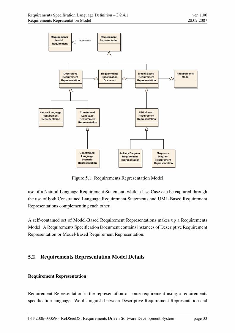
Requirements Specification Language Definition – D2.4.1Requirements Representation Model
ver. 1.0028.02.2007
Requirement Representation
Descriptive Requirement
Representation
Model-Based Requirement
Representation
UML-Based Requirement
Representation
Activity Diagram Requirement
Representation
Sequence Diagram
Requirement Representation
Natural Language Requirement
Representation
Constrained Language
Requirement Representation
Constrained Language Scenario
Representation
Requirements Model::
Requirement
Requirements Model
Requirements Specification
Document
represents
Figure 5.1: Requirements Representation Model
use of a Natural Language Requirement Statement, while a Use Case can be captured throughthe use of both Constrained Language Requirement Statements and UML-Based RequirementRepresentations complementing each other.
A self-contained set of Model-Based Requirement Representations makes up a RequirementsModel. A Requirements Specification Document contains instances of Descriptive RequirementRepresentation or Model-Based Requirement Representation.
5.2 Requirements Representation Model Details
Requirement Representation
Requirement Representation is the representation of some requirement using a requirementsspecification language. We distinguish between Descriptive Requirement Representation and
IST-2006-033596 ReDSeeDS: Requirements Driven Software Development System page 33
Requirements Specification Language Definition – D2.4.1Requirements Representation Model
ver. 1.0028.02.2007
Model-Based Requirement Representation. A combination of both would normally be part of aRequirements Specification Document.
Descriptive Requirement Representation
Descriptive Requirement Representation is the representation of some requirement as specifiedusing a descriptive specification language, e.g., natural language, SVO(O), etc. The need of therequirement is described in this approach, rather than a model of the system to be built.
Natural Language Requirement Representation
Natural Language Requirement Representation is the representation of some requirement asspecified using a natural language, e.g., English, Turkish, Bulgarian, etc. Note, that we techni-cally include also hypertext links into natural-language text, see below. The use of hypertext forrepresenting requirements was already proposed long time ago, see [Kai93, Kai96], but it wasnot yet defined as precisely as below in a metamodel.
Constrained Language Requirement Representation
Constrained Language Requirement Representation is the representation of some requirementas specified using a controlled/constrained natural language, e.g., SVO(O), Attempto ControlledEnglish (ACE), etc. The point is to take advantage of both the formality introduced by a gram-mar of a formal language and still the readability of natural language.
Constrained Language Scenario Representation
Constrained Language Scenario Representation is the representation of some envisioned sce-nario as specified using a constrained language. It gives a precise structure to how such anenvisioned scenario is to be written.
IST-2006-033596 ReDSeeDS: Requirements Driven Software Development System page 34
Requirements Specification Language Definition – D2.4.1Requirements Representation Model
ver. 1.0028.02.2007
Model-Based Requirement Representation
Model-Based Requirement Representation is the representation of some requirement as spec-ified using a modelling language, e.g., UML, etc. In contrast to a Descriptive RequirementRepresentation, the need of a requirement is specified indirectly. The model specifies what thesystem to be built should look like, and the requirement is just to build a system like the onemodelled.
UML-Based Requirement Representation
UML-Based Requirement Representation is the representation of some requirement as specifiedin RSL in parts that are based on UML. Using UML for Model-Based Requirement Represen-tation is actually just one of many ways, but it is one appropriate for today´s practice.
Activity Diagram Requirement Representation
Activity Diagram Requirement Representation is the representation of some requirement asspecified using UML-Based activity diagrams, as specialised for the requirements specificationpurposes.
Interaction Diagram Requirement Representation
Interaction Diagram Requirement Representation is the representation of some requirement asspecified using UML-Based sequence or communication diagrams, as specialised for the re-quirements specification purposes.
IST-2006-033596 ReDSeeDS: Requirements Driven Software Development System page 35
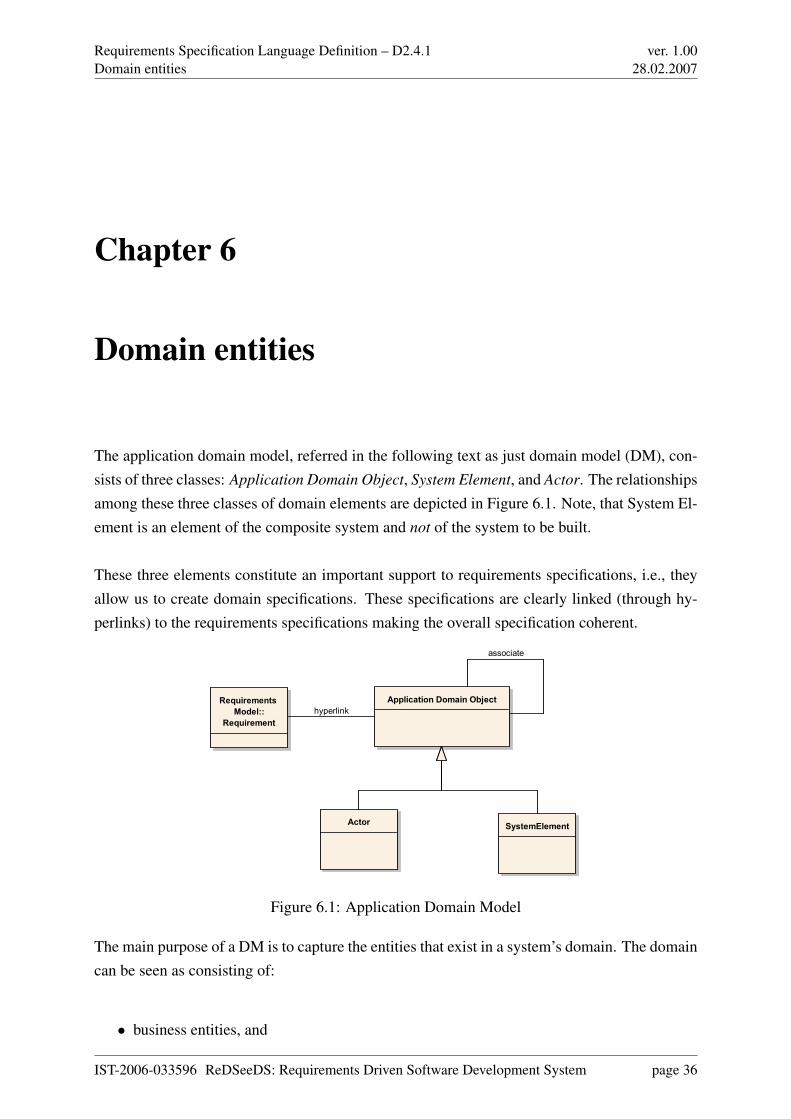
Requirements Specification Language Definition – D2.4.1Domain entities
ver. 1.0028.02.2007
Chapter 6
Domain entities
The application domain model, referred in the following text as just domain model (DM), con-sists of three classes: Application Domain Object, System Element, and Actor. The relationshipsamong these three classes of domain elements are depicted in Figure 6.1. Note, that System El-ement is an element of the composite system and not of the system to be built.
These three elements constitute an important support to requirements specifications, i.e., theyallow us to create domain specifications. These specifications are clearly linked (through hy-perlinks) to the requirements specifications making the overall specification coherent.
Application Domain Object
SystemElementActor
Requirements
Model::
Requirement
associate
hyperlink
Figure 6.1: Application Domain Model
The main purpose of a DM is to capture the entities that exist in a system’s domain. The domaincan be seen as consisting of:
• business entities, and
IST-2006-033596 ReDSeeDS: Requirements Driven Software Development System page 36
Requirements Specification Language Definition – D2.4.1Domain entities
ver. 1.0028.02.2007
• computer entities, including hardware and software (modelled by SystemElement).
In the sections below we discuss these two main groups. In Chapter 7 we present the domainmodel with details of representations for individual domain entities.
6.1 Business entities
A software system is part of a larger business system, and serves as a resource to accomplishbusiness goals. To build a useful DM, we need to study and discover different business entitiesof the domain. The possible sources of business entities are presented below:
1. Business Resources — All entities, both physical and abstract, that exist inside the envi-ronment of the business are business resources. They include people, information, dif-ferent systems, and business supplies and products. They participate in the business pro-cesses. A subset of these resources is a source of modelling entities for the system to bebuilt. The value of tracking and preserving knowledge about these entities is that theseentities are used to perform analysis of the system’s architecture, to track changes to thedomain and the system from the beginning, and to evaluate how well the system reflectscurrent business needs. For an elevator system, an example business resource is the cable
used to pull up the elevator cab.
2. Business Processes — A system to be built may participate later in several business pro-cesses in order to help achieve several business goals. Use cases (UCs) describe sub-processes of larger business processes that are automated by the software system. It isimportant to understand a business process as it relates its UCs, which in turn relate soft-ware requirements that the system has to satisfy. For an elevator system, an examplebusiness process is a passenger’s riding of an elevator cab.
3. Business Rules — Business rules are a major source of constraints on a software system.Many constraints directly influence the system’s architecture. Therefore, it is importantto understand these constraints and to keep track of them, for example, to be able toremove architectural limitations imposed by constraints that do not hold any more. Foran elevator system, an example business rule is the elevator will not change its direction
until it services all previously received calls that lie in the current travelling direction.
The main source of business domain objects are Business Resources, but they are very tightlyinterlinked with Business Processes and Business Rules. In some cases, they cannot exist sep-
IST-2006-033596 ReDSeeDS: Requirements Driven Software Development System page 37
Requirements Specification Language Definition – D2.4.1Domain entities
ver. 1.0028.02.2007
arately. Therefore, we need to seek for domain objects inside business process or business ruledescriptions. These are not intended to be described using structural part of RSL, but can besources to elements expressed in RSL.
6.2 System entities
It is often a case that we are building a new system for which the domain consists of an alreadyexisting computer-based system that includes both software and hardware. For such a system,domain entities are not some “natural” objects but rather software and hardware componentsand other building blocks. Also, taking into account types of systems such as operating sys-tems, compilers, embedded device controllers, shells, GUI libraries, etc. which are all softwaresystems in which all of the domain entities consist purely of what many would call “designcomponents”, while in such cases they are all domain entities. For example, a scheduler is adomain entity and Round-Robin algorithm is a scheduling process. For such domains, the mainaspects of a system that should be modelled are:
• System,
• subsystems,
• modules,
• connectors,
• processes, and
• hardware devices.
The System1 entity defines the outermost boundary of the system under consideration. TheSystem serves as a container for all other entities, and defines the system as a resource in thebusiness system.
A subsystem is a part of a System or a subsystem, being an abstraction of actual physical mod-ules, connectors, and processes. It serves as a container and a building block.
A module is a basic architectural building block. For example, in the logical view, it representsa entity that occurs in a domain, and in the implementation view, it represents a code unit.
1Note that this “system” is spelled out with initial uppercase letter to distinguish it from the generic “system”used elsewhere.
IST-2006-033596 ReDSeeDS: Requirements Driven Software Development System page 38
Requirements Specification Language Definition – D2.4.1Domain entities
ver. 1.0028.02.2007
Modules are abstractions of basic building blocks of the domain, depending on the developmenttechnology used.
A connector is an abstraction of a communication mechanism or a channel that exists in asystem. Its size and complexity vary from a simple procedure call to a connection on theInternet.
A process is an executable piece of software. Processes are basic building blocks of a run-timearchitectural view.
A hardware device is an entity that occurs in the run-time architectural view, and it represents aphysical device that is a part of the system.
The above types of system entities have their place in the domain model created at the require-ments level, using the structural part of RSL. The System entity is used throughout the de-scriptions of functional requirements in general, and in use case descriptions (scenarios) specif-ically. Other system entities can be used in requirements that specify technical constraints onthe prospective system.
IST-2006-033596 ReDSeeDS: Requirements Driven Software Development System page 39
Requirements Specification Language Definition – D2.4.1Representation of domains
ver. 1.0028.02.2007
Chapter 7
Representation of domains
7.1 Overview
When considering requirements specifications as described in Chapters 4 and 5 we should ob-serve that they do not contain any descriptions of the application (or: problem) domain. In theRequirements Specification Language we clearly want to separate the requirements with theirrepresentations from the representations of the problem domain. Thus, none of the require-ments representations allows for defining elements of the problem domain. They only allow fordefining the system behaviour or quality in their pure form. No interleaving of domain elementdefinitions are allowed.
The main rationale behind this clear distinction is to make requirements specifications unam-biguous and consistent. We need to remember that the main purpose of a requirements specifi-cation in software engineering is to reflect the real needs of the clients. This specification shouldbe the basis on which developers build a software system of good quality – i.e. a system thatmeets the clients’ expectations to a high extent. Unfortunately, a commonly encountered prob-lem with requirements specifications is that they are imprecise and have many inconsistences.Specifications are often written using a natural written language style or, on the contrary, theyare too general. In both cases, the intentions of the writer are hard to understand and interpretcausing ambiguity. The majority of requirements specification writers tend to mix descriptionsof the system’s behaviour, quality or appearance with descriptions of objects (or: notions) con-tained in the problem domain. Definitions of notions are buried in many different places insidescenarios, stories or simply free text. What is more harmful, the same notions often have con-flicting definitions and, on the other hand, a number of different synonyms are used to describeidentically (or close to identically) defined notions.
IST-2006-033596 ReDSeeDS: Requirements Driven Software Development System page 40
Requirements Specification Language Definition – D2.4.1Representation of domains
ver. 1.0028.02.2007
Having the requirements specification of such a poor quality, it is a very hard task to builda system that fully fulfills the real clients’ needs. It is hard to reflect these requirements inthe architecture and in the design of the prospective system as well as to apply changes in thesystem when requirements change. Finally, imprecise requirements make it close to impossibleto apply the concept of software reuse at the level of problem definition.
To overcome all problems mentioned above, we need a separate part of our language that sup-ports creating precise and consistent requirements specifications through the introduction of aseparate specification of the domain. The precision of requirements specifications is assuredby using hyperlinks that link requirements text with definitions of phrases and terms. Thesehyperlinks can be embedded in free text requirement representations, structured language rep-resentations (like SVO sentences) and textual parts of model-based representations.
Let’s consider a simple scenario, forming part of a requirement representation written in theSVO format. This scenario describes a sequence of interactions between a customer of a fitnessclub and the fitness club system:
• Customer wants to sign up for exercises.
• System shows time schedule.
• Customer chooses time from time schedule.
With these simple sentences we can precisely describe actions performed by the actor (Customeror System). It can be noted, however, that such sentences do not contain definitions of notionsused therein. For example, we lack an explanation of what ‘exercises’ or ‘time schedule’ is, andhow they relate to each other. In order to avoid inconsistencies, as mentioned above, we shouldnot insert definitions of notions into the sentences. In fact, the RSL does not allow for insertingsuch definitions into structured sentences (like SVO). However, no restriction is set on naturallanguage sentences. With such sentences, the requirements specifiers are strongly advised not toput domain element definitions into this free text. Instead, a hyperlink should be introduced thatpoints to an appropriate definition in the domain specification. This prevents from introducingcontradictory definitions of the same notion in different places of the requirements specification.
Considering the above, the Requirements Specification Language provides a means to describethe problem domain of the system. We can crete domain specifications that contain domain
element packages – repositories that keep all necessary notions from the domain along with theirdefinitions and relationships between them. For the above example, the domain specificationwould contain the following definitions for nouns:
IST-2006-033596 ReDSeeDS: Requirements Driven Software Development System page 41
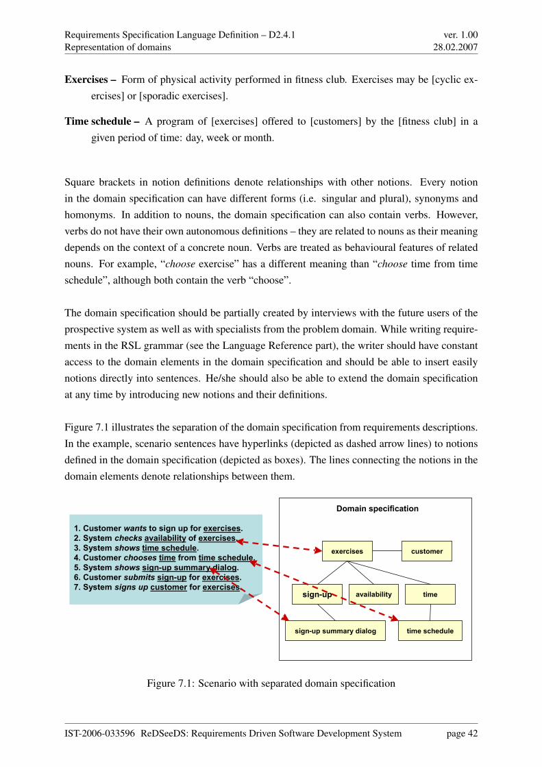
Requirements Specification Language Definition – D2.4.1Representation of domains
ver. 1.0028.02.2007
Exercises – Form of physical activity performed in fitness club. Exercises may be [cyclic ex-ercises] or [sporadic exercises].
Time schedule – A program of [exercises] offered to [customers] by the [fitness club] in agiven period of time: day, week or month.
Square brackets in notion definitions denote relationships with other notions. Every notionin the domain specification can have different forms (i.e. singular and plural), synonyms andhomonyms. In addition to nouns, the domain specification can also contain verbs. However,verbs do not have their own autonomous definitions – they are related to nouns as their meaningdepends on the context of a concrete noun. Verbs are treated as behavioural features of relatednouns. For example, “choose exercise” has a different meaning than “choose time from timeschedule”, although both contain the verb “choose”.
The domain specification should be partially created by interviews with the future users of theprospective system as well as with specialists from the problem domain. While writing require-ments in the RSL grammar (see the Language Reference part), the writer should have constantaccess to the domain elements in the domain specification and should be able to insert easilynotions directly into sentences. He/she should also be able to extend the domain specificationat any time by introducing new notions and their definitions.
Figure 7.1 illustrates the separation of the domain specification from requirements descriptions.In the example, scenario sentences have hyperlinks (depicted as dashed arrow lines) to notionsdefined in the domain specification (depicted as boxes). The lines connecting the notions in thedomain elements denote relationships between them.
1. Customer wants to sign up for exercises.2. System checks availability of exercises.3. System shows time schedule.4. Customer chooses time from time schedule.5. System shows sign-up summary dialog.6. Customer submits sign-up for exercises.7. System signs up customer for exercises.
1. Customer wants to sign up for exercises.2. System checks availability of exercises.3. System shows time schedule.4. Customer chooses time from time schedule.5. System shows sign-up summary dialog.6. Customer submits sign-up for exercises.7. System signs up customer for exercises.
customer
time schedule
exercises
sign-up
sign-up summary dialog
timeavailability
Domain specification
Figure 7.1: Scenario with separated domain specification
IST-2006-033596 ReDSeeDS: Requirements Driven Software Development System page 42
Requirements Specification Language Definition – D2.4.1Representation of domains
ver. 1.0028.02.2007
7.2 Domain representations using conceptual models
An application domain can be modelled by representing its important concepts and entities in amodel. Such conceptual models are usually built from symbols, most popular today is object-oriented representation. An object is usually represented by a class that it is an abstraction ofan entity in the application domain.
Unfortunately, representations in object-oriented classes are often confused to be representa-tions of a software design rather than that of an application domain. Such a model typicallycontains operations in the class definitions, which are already operations of a software object.
That is why we define for our RSL a special kind of structural domain representation thatexplicitly focuses on domain elements. In particular, such a representation does not even allowthe inclusion of operations for a conceptual domain model. Apart from that, however, it allowsrepresentations according to the following key object-oriented principles:
• Domain elements can be generalised (and inversely specialised).
• Domain elements can be connected through domain element associations.
• Domain elements associations can be aggregations.
• Domain element associations can have multiplicities.
These are actually the same principles as those behind an ontology. In contrast to the originof this notion stemming from the old Greek culture and language, an ontology is today con-sidered a formal representation of a domain. In the field of Artificial Intelligence, even specialontology languages have been defined for this purpose, based on formal approaches to so-calledknowledge representation.
Still, while not completely formal in a pure sense, a representation in UML or using our domainelements approach derived from it, may still be considered to result in a simple form of a usableontology.
Even when having a representation in a model according to these principles (being more or lessformal), the meaning of a domain entity is often not really obvious for a human and is sometimesjust inductively inferred from the name. That is why dictionaries with glossary information areusually suggested, but they are often kept separately and, therefore, not easily accessible.
IST-2006-033596 ReDSeeDS: Requirements Driven Software Development System page 43
Requirements Specification Language Definition – D2.4.1Representation of domains
ver. 1.0028.02.2007
The RETH tool, for example, embedded for each domain object their glossary entries in apredefined attribute (see, [Kai96, Kai97]). In RSL, we include similar descriptions in notionsof the domain elements.
7.3 Domain representation using phrases
Conceptual specification of a particular domain is an important element of any software devel-opment project (a so called software case). However, conceptual specification is not enough todescribe the full specification of the problem domain. This specification should be referencedthroughout all the requirements, as pointed out in Section 7.1. The conceptual model allows usto define noun notions, but we also need to define certain phrases containing verbs or adjectives.Such phrases could be used in constrained language requirement representations. At the sametime, definitions of these phrases could be kept consistently in a single coherent terminology.
Thus, the RSL introduces a capability to attach to domain elements, certain statements in theform of phrases. The simplest statement contains just the noun with its description (usinghypertext). More complex statements contain verb phrases and quantifier or modifier phrases.It is important that every phrase is tightly combined with the noun being part of it. This way, thedomain elements are highly structured, where the structure is reflected through the conceptualspecification with associations between domain elements (i.e. nouns).
In RSL, every domain element can include many phrases referring to the same noun. Thesephrases can contain wiki-like descriptions (text with hyperlinks relating to other domain ele-ments or phrases). It can be noted that the name of every domain element is a phrase containinga noun and an optional modifier or quantifier (eg. user, additional user).
This way, the domain specification becomes coherently embedded into the conceptual modeldescribed in the previous section. The RSL shows an overview of all the phrases contained in adomain element. The domain specification can be shown on domain element diagrams (insidedomain element icons), and can be presented in a traditional textual form.
Phrases that form the domain specification ensure a clear separation of concerns (behaviourand quality vs. problem domain description) which guarantees consistency of requirements ex-pressed. These phrases form pieces for a constrained language to be used elsewhere throughoutthe RSL. This approach facilitates the creation of RSL specifications through the use of phrasesas atomic “phrase lexemes”. Any phrase can be perceived as a complex domain element. Byusing phrase lexemes we can easily define grammars based on such complex elements. For
IST-2006-033596 ReDSeeDS: Requirements Driven Software Development System page 44
Requirements Specification Language Definition – D2.4.1Representation of domains
ver. 1.0028.02.2007
example we can define a Subject-Verb-Objects (SVO[O]) sentence using just two phrases: asubject phrase and a predicate phrase. Subject can include any noun from the conceptual speci-fication optionally grouped with its quantifier and modifier (which together form a noun phrase,e.g. every registered customer, authorised user). Predicate is a more complex phrase, contain-ing a verb and possibly referring to some other notion (it is a noun phrase). Such a VerbPhraseforms the VO (simple verb phrase) or VOO (complex verb phrase pointing also to another no-tion) part of the sentence. Let’s now consider the following example sentences that use theSVO(O) grammar:
• User submits form.
• System adds user to the user list.
• Registered customer cancels reservation.
The first sentence consists of the user phrase (a noun with no quantifier or modifier) in therole of a subject and the submits form simple verb phrase in the role of a predicate (VO partof the sentence). The second sentence consists of the system phrase in the role of a subjectand the adds user to the user list complex verb phrase (pointing to the user list notion) in therole of predicate (VOO part of the sentence). In the third sentence we have an example of amore complex noun phrase registered customer (containing a modifier). For more details andexamples please refer to Chapter 6
7.4 Terminology
In order to build phrases as described in the previous section, we need terms. Terms are universaland have general meaning as specified in natural language dictionaries, and they have specificmeaning in the context of a software project (or group of projects). Terms have inflectionsdepending on the particular natural language used (English has different inflections than Polishfor instance).
The dictionary defines terms (nouns, verbs, adjectives, etc.) with their inflections. Every termis equivalent to a lexeme used in other specifications. It can be noted however, that for a singleterm, many lexemes can be formed — one for each natural language that we use in our specifi-cations. The dictionary organised in this form can greatly facilitate formulation and comparisonof requirements in different languages (especially important on the EU market).
IST-2006-033596 ReDSeeDS: Requirements Driven Software Development System page 45
Requirements Specification Language Definition – D2.4.1Representation of domains
ver. 1.0028.02.2007
Thus, in RSL we separate the phrases for a given domain from a global dictionary common forall software cases. This separation allows facilitating reuse of specifications in the RSL, as itallows for combining the common dictionary with a thesaurus.
The word thesaurus originates in Latin and Greek, meaning “treasury”. In the 19th century,a thesaurus was a book of jargon for a specialised field. Today, a thesaurus is an orderedcomposition of terms from an application domain or area with their relations [Bro03]. Relationsdefined in a thesaurus are, e.g., synonym (similar term), antonym (opposite) and hierarchicalrelations (“broader term” and “narrower term”).1 These relations define the lexical semanticsof terms. Based on the lexical semantics of terms it is possible to compare requirements, i.e.,the similarity of requirements can be measured based on the lexical semantics defined in thethesaurus.
In fact, a dictionary and a thesaurus complement one another. The dictionary provides a textualdescription, information about inflections and possibly translations to other languages, while thethesaurus describes the relation of a term to other terms. In RSL this combination of dictionaryand thesaurus is placed in the terminology package. The RSL allows for specifying a thesaurusthrough adding relationships between terms. These relationships can be depicted graphically asspecified in the language reference.
The combination of dictionary and thesaurus features within one structure is not new. TheWordNet lexical database is a well-known example of such a combination that interlinks En-glish nouns, verbs, adjectives and adverbs in a wordnet [MBF+90], [Mil90], [GM90], [BMT90].Similar wordnets also exist for other European languages (e.g., for German see the Wortschatz-lexikon http://wortschatz.uni-leipzig.de). EuroWordNet, for example was a European resourcesand development project2 providing a multilingual database with wordnets for several Europeanlanguages (Dutch, Italian, Spanish, German, French, Czech and Estonian) [VPG99]. Lexical se-mantics defined in wordnets can be used to improve the results in information retrieval [Kur04],[CEE+04], e.g., through support for resolving ambiguities.
The use of a wordnet in information retrieval is not new as stated above. Using a wordnet forcomparing software requirements is innovative, however.
1Thesauri are standardised, e.g. in DIN 1463-1 (German Industry Norm) and ISO 2788 (International Stan-dardisation Organisation).
2Project reference number LE-2 4003 & LE-4 8328; http://www.illc.uva.nl/EuroWordNet/index.html
IST-2006-033596 ReDSeeDS: Requirements Driven Software Development System page 46
Requirements Specification Language Definition – D2.4.1Representing the user interface and its dynamics
ver. 1.0028.02.2007
Chapter 8
Representing the user interface and itsdynamics
8.1 Elements of the user interface
In order to enable analysts specify user interface requirements in a notation understandable totheir stakeholders, prototype-oriented model-based elements are required. This section definessuch user interface elements. Since concrete user interface elements mainly differ according tomodality and toolkit and there are currently many modalities and toolkits, general user interfaceelements should be defined independent therefrom. The RSL therefore provides general usage-oriented UIElements that are both modality and toolkit independent. Extending the UIElementsand hence tailoring them to concrete elements of a specific domain is an important requirement,which is done by using UML profiles.
In order to obtain general UIElements, the usage of different concrete user interface elementsfrom different sources were analyzed. There are elements for direct interaction with the user andothers for structuring the user interface for example by grouping other elements. Consequentlythe former elements are regarded as simple or atomic while the latter ones are containers. Thismodality and toolkit independent classification is showed in Figure 8.1.
Chapter 15 of this document provides a detailed description of these elements.
IST-2006-033596 ReDSeeDS: Requirements Driven Software Development System page 47
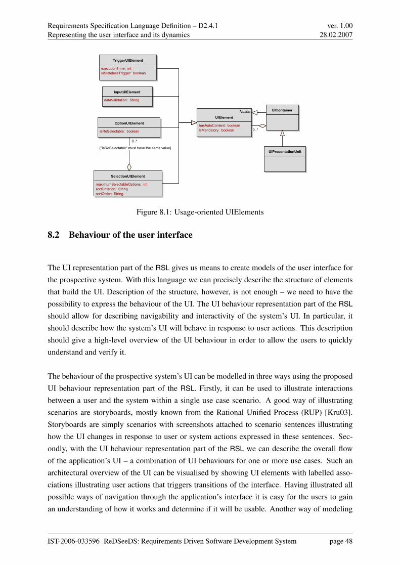
Requirements Specification Language Definition – D2.4.1Representing the user interface and its dynamics
ver. 1.0028.02.2007
Notion
UIElement
hasAutoContent: boolean
isMandatory: boolean
InputUIElement
dataValidation: String
OptionUIElement
isReSelectable: boolean
SelectionUIElement
maximumSelectableOptions: int
sortCriterion: String
sortOrder: String
TriggerUIElement
executionTime: int
isStatelessTrigger: boolean
UIContainer
UIPresentationUnit
0..*
0..*
{"isReSelectable" must have the same value}
Figure 8.1: Usage-oriented UIElements
8.2 Behaviour of the user interface
The UI representation part of the RSL gives us means to create models of the user interface forthe prospective system. With this language we can precisely describe the structure of elementsthat build the UI. Description of the structure, however, is not enough – we need to have thepossibility to express the behaviour of the UI. The UI behaviour representation part of the RSL
should allow for describing navigability and interactivity of the system’s UI. In particular, itshould describe how the system’s UI will behave in response to user actions. This descriptionshould give a high-level overview of the UI behaviour in order to allow the users to quicklyunderstand and verify it.
The behaviour of the prospective system’s UI can be modelled in three ways using the proposedUI behaviour representation part of the RSL. Firstly, it can be used to illustrate interactionsbetween a user and the system within a single use case scenario. A good way of illustratingscenarios are storyboards, mostly known from the Rational Unified Process (RUP) [Kru03].Storyboards are simply scenarios with screenshots attached to scenario sentences illustratinghow the UI changes in response to user or system actions expressed in these sentences. Sec-ondly, with the UI behaviour representation part of the RSL we can describe the overall flowof the application’s UI – a combination of UI behaviours for one or more use cases. Such anarchitectural overview of the UI can be visualised by showing UI elements with labelled asso-ciations illustrating user actions that triggers transitions of the interface. Having illustrated allpossible ways of navigation through the application’s interface it is easy for the users to gainan understanding of how it works and determine if it will be usable. Another way of modeling
IST-2006-033596 ReDSeeDS: Requirements Driven Software Development System page 48
Requirements Specification Language Definition – D2.4.1Representing the user interface and its dynamics
ver. 1.0028.02.2007
UI behaviour is associating elements of user interface (UIElements) with RequirementsSpecifi-
cations :: UseCases – every UIElement can trigger a Use Case, in other words, user can begininteraction with system by using element of interface (graphical, voice or other).
Chapter 16 of this document provides a detailed description on how the UI behaviour can berepresented using the UI behaviour representation part of the RSL.
IST-2006-033596 ReDSeeDS: Requirements Driven Software Development System page 49
Requirements Specification Language Definition – D2.4.1Discussion
ver. 1.0028.02.2007
Chapter 9
Discussion
Requirements can be compared to novels in literature. Good novels communicate stories treatedas sequences of events, and place these stories in a well described environment. Unfortunately,writing “stories” that describe requirements for software systems seems to be equally as hard as(or harder) than as writing good novels. However, unlike writing novels, lack of coherence andambiguities may cause disaster when developing a system based on such requirements.
Finding inconsistencies in a set of several tens or hundreds of requirements is quite a hardtask, especially, when these requirements are written by different people and at different times.It seems that keeping the vocabulary separate from the rest of the requirements specificationcan significantly facilitate keeping sparse requirements documents consistent by keeping thevocabulary controlled. This is because most inconsistencies in requirements are caused bycontradictory definitions of terms. To eliminate the source of such inconsistencies we introducea single repository of notions (a vocabulary) that can be used in various requirements. Thismeans that for instance, the behavioural requirements could use definitions already found in therepository and just concentrate on the actual sequence of events.
In addition to the above, having a clearly defined vocabulary makes it possible to introducecertain query mechanisms that would allow for easy retrieval and reuse of requirements. Forsuch mechanisms it is very important to be able to compare requirements. This comparisonshould be based on a terminology where terms with similar meaning are related.
In fact, our thesaurus (as integrated with a dictionary in our vocabulary representation) involvesa specialisation relation (and indirectly the inverse generalisation). While this is not unusualfor a thesaurus, a complication arises since we link the thesaurus also with a conceptual model,which involves generalisation / specialisation as well. As long as only one of these approaches
IST-2006-033596 ReDSeeDS: Requirements Driven Software Development System page 50
Requirements Specification Language Definition – D2.4.1Discussion
ver. 1.0028.02.2007
will be used for domain representation, this does not pose a problem. Just to the contrary, inthe absence of a conceptual model, a thesaurus can define such hierarchies. Whenever bothapproaches will be used at the same time, however, these relations are somewhat redundant andmay, therefore, result in inconsistencies.
One approach to tackle this problem may be to automatically generate a generalisation / spe-cialisation hierarchy for a not yet existing conceptual model from the related hierarchy in thethesaurus (using tool support, of course). Such an approach was taken in [SK94] for a unifiedhypertext and structured object representation as defined in [KS91]. This representation is sim-ilar enough to ours to make this approach promising. Another approach would be to implementautomatic consistency checks in a tool. Since one representation is clearly less formal than theother, this approach may be difficult to pursue.
So, it has to be stressed that the language to define vocabularies should be used in conjunctionwith a tool. This is highly recommended as using notions stored in a vocabulary within re-quirements and keeping it constantly coherent would be very laborious and error-prone if donemanually. Thus such a tool would need to allow for providing consistency between differentrequirements using the same notions (the notion has the same definition wherever it is used).
Going back to the original IEEE Std 610.12-1990: IEEE Standard Glossary of Software Engi-neering Terminology definition of requirement that we used for this project:
1. A condition or capability needed by a user to solve a problem or achieve an objective.
2. A condition or capability that must be met or possessed by a system or system componentto satisfy a contract, standard, specification, or other formally imposed documents.
3. A documented representation of a condition or capability as in (1) or (2).
we can see in (3) that it includes the documented representation of the requirement. Duringthis project we realised that the documented representation of the requirement should not beconsidered to be the requirement itself, but a representation. There are several reasons:
• A requirement is something that exists even if it is never documented, i.e., represented.
• A requirement can have multiple representations.
• A requirement can be represented at different abstraction levels.
IST-2006-033596 ReDSeeDS: Requirements Driven Software Development System page 51
Requirements Specification Language Definition – D2.4.1Discussion
ver. 1.0028.02.2007
• Each representation of a requirement is usually not complete from each possible perspec-tive.
The first issue tackles the fact that requirements and their representations belong to two differ-ent dimensions. Similar to real world entities and the OOA representations, an orange in thereal world is different than an orange represented using UML. Besides the fact that it is veryhard to elicit all requirements and represent them properly, even when they are elicited, theirrepresentations are not necessarily the right ones.
The second issue is that each requirement can be represented in multiple ways and some can berepresented in certain ways that others cannot. For example requirements concerning differentsound types and ranges are hard to capture using UML sequence diagrams.
The third issue is that requirements can be represented at different abstraction levels leavingsome part of the actual requirement out. By doing this any single requirement representationabstraction level represents no full requirement. On the other hand, requirements themselvesare harder to decompose into multiple abstraction levels.
Finally, taking into account that each requirement can be represented in a number of differentways, and for each way at different abstraction levels, it is obvious that almost any requirementsrepresentation cannot be considered as complete representation of the requirement and as suchdifferent than the requirement itself.
This distinction between requirements and their representations is evident throughout our lan-guage. As such, it removes the confusion between requirements themselves and their represen-tations that commonly exists in the requirements engineering community. The removal of thisproblem is one of the prerequisites for successful capture of the requirements, proper traceabil-ity, and quality insurance involved in checking that requirement specification is consistent andcomplete. This is one of the major contributions of our language and this project.
IST-2006-033596 ReDSeeDS: Requirements Driven Software Development System page 52
Requirements Specification Language Definition – D2.4.1 ver. 1.0028.02.2007
Part II
Language Reference
IST-2006-033596 ReDSeeDS: Requirements Driven Software Development System page 53
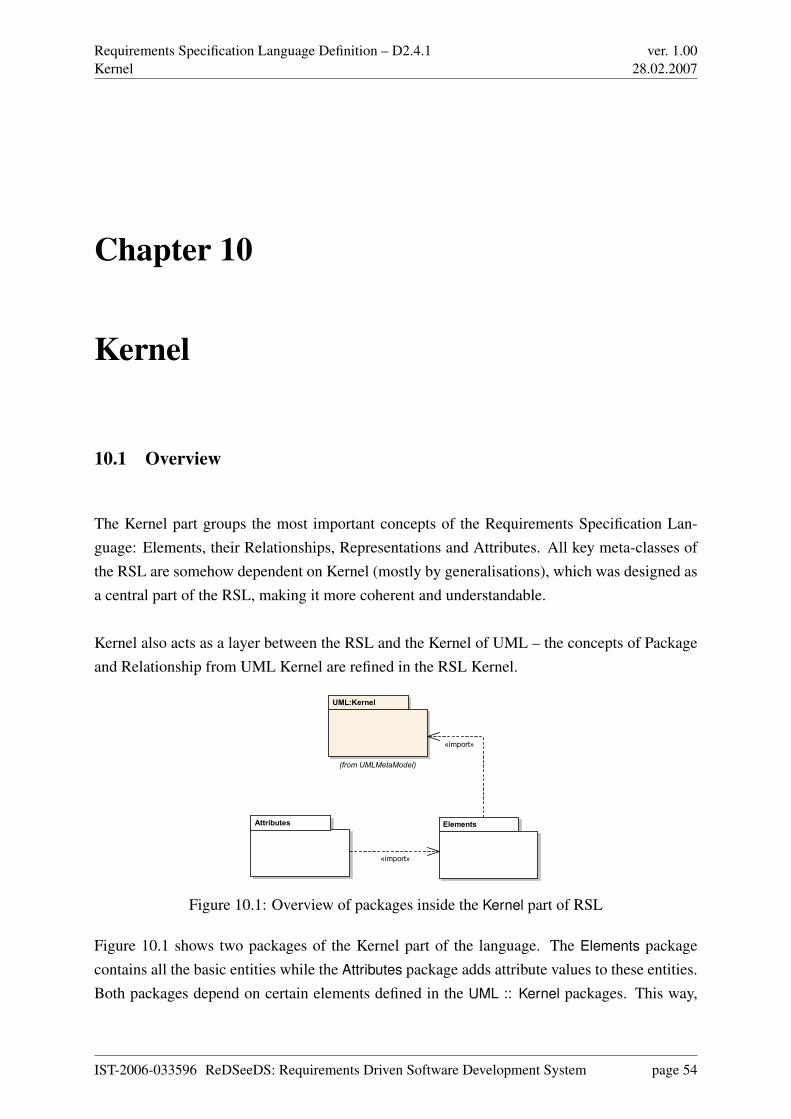
Requirements Specification Language Definition – D2.4.1Kernel
ver. 1.0028.02.2007
Chapter 10
Kernel
10.1 Overview
The Kernel part groups the most important concepts of the Requirements Specification Lan-guage: Elements, their Relationships, Representations and Attributes. All key meta-classes ofthe RSL are somehow dependent on Kernel (mostly by generalisations), which was designed asa central part of the RSL, making it more coherent and understandable.
Kernel also acts as a layer between the RSL and the Kernel of UML – the concepts of Packageand Relationship from UML Kernel are refined in the RSL Kernel.
Attributes Elements
UML:Kernel
(from UMLMetaModel)
«import»
«import»
Figure 10.1: Overview of packages inside the Kernel part of RSL
Figure 10.1 shows two packages of the Kernel part of the language. The Elements packagecontains all the basic entities while the Attributes package adds attribute values to these entities.Both packages depend on certain elements defined in the UML :: Kernel packages. This way,
IST-2006-033596 ReDSeeDS: Requirements Driven Software Development System page 54
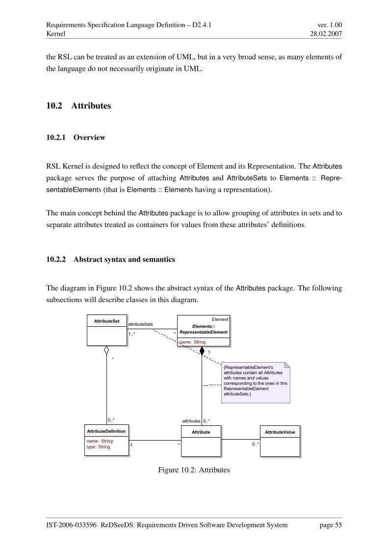
Requirements Specification Language Definition – D2.4.1Kernel
ver. 1.0028.02.2007
the RSL can be treated as an extension of UML, but in a very broad sense, as many elements ofthe language do not necessarily originate in UML.
10.2 Attributes
10.2.1 Overview
RSL Kernel is designed to reflect the concept of Element and its Representation. The Attributes
package serves the purpose of attaching Attributes and AttributeSets to Elements :: Repre-
sentableElements (that is Elements :: Elements having a representation).
The main concept behind the Attributes package is to allow grouping of attributes in sets and toseparate attributes treated as containers for values from these attributes’ definitions.
10.2.2 Abstract syntax and semantics
The diagram in Figure 10.2 shows the abstract syntax of the Attributes package. The followingsubsections will describe classes in this diagram.
Attribute
AttributeSet
AttributeDefinition
name: String
type: String
AttributeValue
Element
Elements::
RepresentableElement
name: String
{RepresentableElement's
attributes contain all Attributes
with names and values
corresponding to the ones in this
RepresentableElement
attributeSets.}
*1 0..*
attributes 0..*
1
0..*
*
*
attributeSets
1..*
Figure 10.2: Attributes
IST-2006-033596 ReDSeeDS: Requirements Driven Software Development System page 55
Requirements Specification Language Definition – D2.4.1Kernel
ver. 1.0028.02.2007
Attribute
Semantics. An Attribute is an entity containing properties of various elements. Attribute is de-fined by AttributeDefinition. Attributes can be grouped in AttributeSets. Attribute is a containerfor value(s), which are attached to Elements :: RepresentableElements (which is constrainedby existence of Attribute’s definition in an AttributeSet corresponding to this Elements :: Repre-
sentableElement).Abstract syntax. Attribute is a component of Elements :: RepresentableElement, but only ifits definition exists in the AttributeSet associated with this Elements :: RepresentableElement.Attribute is also associated with AttributeDefinition (many Attributes can be associated with onedefinition). Attribute can have multiple AttributeValues associated with it.
AttributeDefinition
Semantics. AttributeDefinition is a description of associated Attribute and a constraint for itsvalues. Attribute can have a name (AttributeDefinition’s name attribute) and type (type attribute,which determines the set of possible values of AttributeValue).Abstract syntax. AttributeDefinition can be a component of several AttributeSets. AttributeDefi-
nition can be associated with Attributes.
AttributeSet
Semantics. AttributeSet is an entity grouping Attributes via their definitions (AttributeDefini-
tion). AttributeSets can be associated with Elements :: RepresentableElements, which restrictsattachment of Attributes to those elements. AttributeSet can be treated as a template for Attributes
that should be connected to given Elements :: RepresentableElement.Abstract syntax. AttributeSet is a container for AttributeDefinitions. AttributeSet is associatedwith Elements :: RepresentableElements.
AttributeValue
Semantics. AttributeValue represents a value of a property associated with a Elements :: Repre-
sentableElement.Abstract syntax. AttributeValues can be associated with an Attribute.
IST-2006-033596 ReDSeeDS: Requirements Driven Software Development System page 56
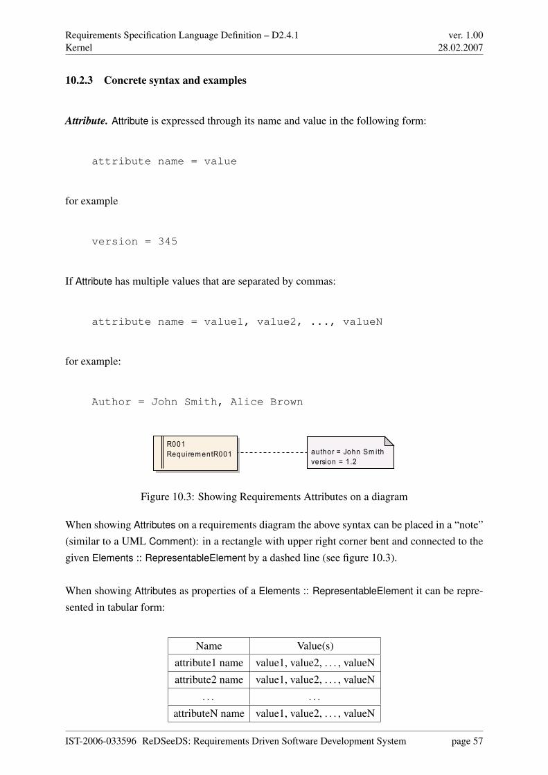
Requirements Specification Language Definition – D2.4.1Kernel
ver. 1.0028.02.2007
10.2.3 Concrete syntax and examples
Attribute. Attribute is expressed through its name and value in the following form:
attribute name = value
for example
version = 345
If Attribute has multiple values that are separated by commas:
attribute name = value1, value2, ..., valueN
for example:
Author = John Smith, Alice Brown
R001Requi rem entR001 author = John Sm ith
version = 1.2
Figure 10.3: Showing Requirements Attributes on a diagram
When showing Attributes on a requirements diagram the above syntax can be placed in a “note”(similar to a UML Comment): in a rectangle with upper right corner bent and connected to thegiven Elements :: RepresentableElement by a dashed line (see figure 10.3).
When showing Attributes as properties of a Elements :: RepresentableElement it can be repre-sented in tabular form:
Name Value(s)
attribute1 name value1, value2, . . . , valueN
attribute2 name value1, value2, . . . , valueN
. . . . . .
attributeN name value1, value2, . . . , valueN
IST-2006-033596 ReDSeeDS: Requirements Driven Software Development System page 57
Requirements Specification Language Definition – D2.4.1Kernel
ver. 1.0028.02.2007
AttributeDefinition. Attribute can be shown in the form of a listing of its attributes and valueswith a caption showing its definition’s name:
attribute definition name
name = attribute name
type = attribute type
for example
Version attribute definition
name = version
type = Integer
AttributeSet. AttributeSet can be shown as a listing of attributes’ names and types defined in theAttributeDefinitions owned by this AttributeSet (every attribute in separate line), along with thisAttributeSet’s name:
attribute set name
attribute1 name (attribute1 type)
attribute2 name (attribute2 type)
...
attributeN name (attributeN type)
for example
Requirements attributes
author (String)
version (Number)
AttributeValue. AttributeValue can be shown in a way similar to the Attribute (see above).
IST-2006-033596 ReDSeeDS: Requirements Driven Software Development System page 58
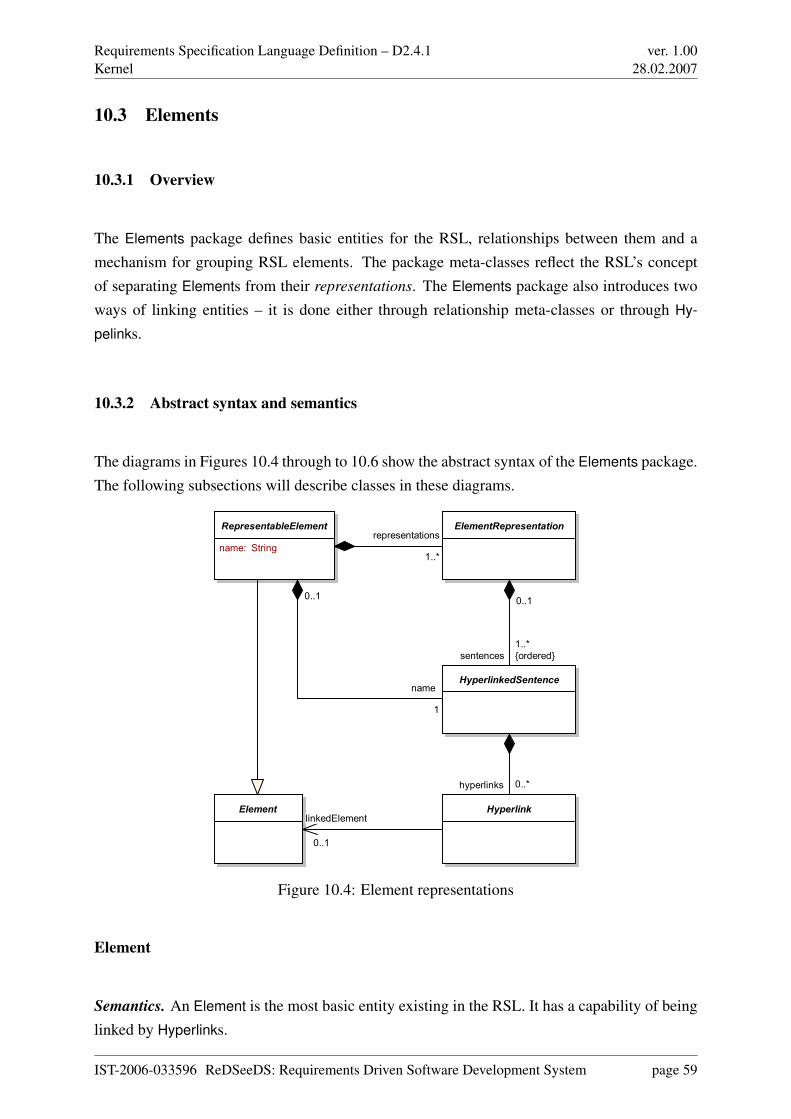
Requirements Specification Language Definition – D2.4.1Kernel
ver. 1.0028.02.2007
10.3 Elements
10.3.1 Overview
The Elements package defines basic entities for the RSL, relationships between them and amechanism for grouping RSL elements. The package meta-classes reflect the RSL’s conceptof separating Elements from their representations. The Elements package also introduces twoways of linking entities – it is done either through relationship meta-classes or through Hy-
pelinks.
10.3.2 Abstract syntax and semantics
The diagrams in Figures 10.4 through to 10.6 show the abstract syntax of the Elements package.The following subsections will describe classes in these diagrams.
RepresentableElement
name: String
ElementRepresentation
HyperlinkedSentence
HyperlinkElement
representations
1..*
name
1
0..1
sentences
1..*
{ordered}
0..1
hyperlinks 0..*
linkedElement
0..1
Figure 10.4: Element representations
Element
Semantics. An Element is the most basic entity existing in the RSL. It has a capability of beinglinked by Hyperlinks.
IST-2006-033596 ReDSeeDS: Requirements Driven Software Development System page 59
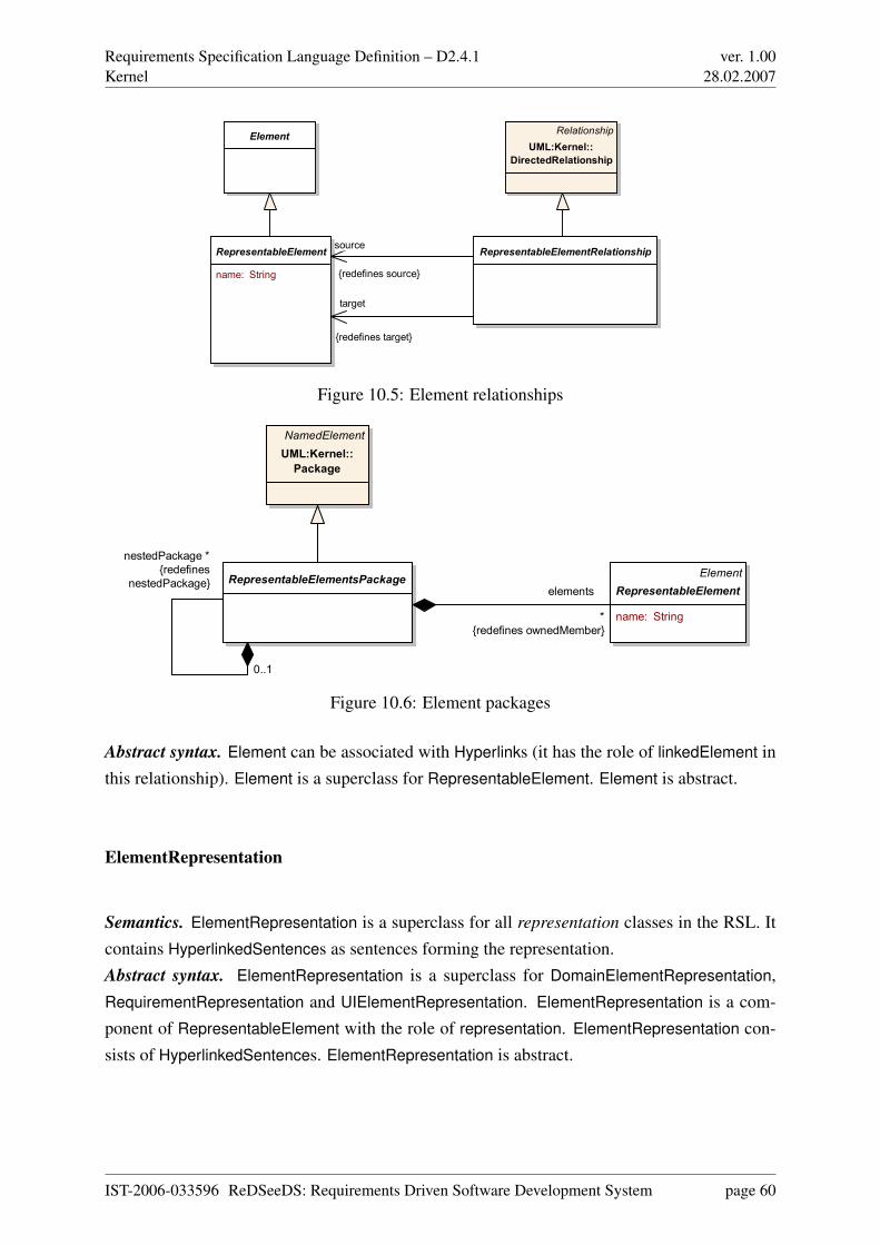
Requirements Specification Language Definition – D2.4.1Kernel
ver. 1.0028.02.2007
RepresentableElement
name: String
RepresentableElementRelationship
ElementRelationship
UML:Kernel::
DirectedRelationship
target
{redefines target}
source
{redefines source}
Figure 10.5: Element relationships
Element
RepresentableElement
name: String
RepresentableElementsPackage
NamedElement
UML:Kernel::
Package
elements
*
{redefines ownedMember}
nestedPackage *
{redefines
nestedPackage}
0..1
Figure 10.6: Element packages
Abstract syntax. Element can be associated with Hyperlinks (it has the role of linkedElement inthis relationship). Element is a superclass for RepresentableElement. Element is abstract.
ElementRepresentation
Semantics. ElementRepresentation is a superclass for all representation classes in the RSL. Itcontains HyperlinkedSentences as sentences forming the representation.Abstract syntax. ElementRepresentation is a superclass for DomainElementRepresentation,RequirementRepresentation and UIElementRepresentation. ElementRepresentation is a com-ponent of RepresentableElement with the role of representation. ElementRepresentation con-sists of HyperlinkedSentences. ElementRepresentation is abstract.
IST-2006-033596 ReDSeeDS: Requirements Driven Software Development System page 60
Requirements Specification Language Definition – D2.4.1Kernel
ver. 1.0028.02.2007
Hyperlink
Semantics. Hyperlink is used for linking Elements. HyperlinkedSentences are formed of Hyper-
links.Abstract syntax. Hyperlink may point at exactly one Element. Hyperlink is a component ofHyperlinkedSentence. Hyperlink is a base class for Phrases :: PhraseHyperlink and Term ::
TermHyperlink. Hyperlink is abstract.
HyperlinkedSentence
Semantics. HyperlinkedSentence is a base class for various types of sentences in RSL. Hyper-
linkedSentence is a set of Hyperlinks used for representing RepresentableElements.Abstract syntax. HyperlinkedSentence consists of Hyperlinks. HyperlinkedSentence is a com-ponent of ElementRepresentation (with the role of sentences) and RepresentableElement (withthe role of name). HyperlinkedSentence is a superclass for NaturalLanguageHypertextSen-
tence, ConstrainedLanguageSentence and DomainElementHyperlinkedSentence. Hyperlinked-
Sentence is abstract.
RepresentableElement
Semantics. RepresentableElement is a base class for Element’s specialisations which havea representation. RepresentableElements can be grouped in RepresentableElementsPackages.RepresentableElement can be source and target for RepresentableElementRelationships, allow-ing all elements that have representation to be linked in way other than by Hyperlinks. EveryRepresentableElement has its name.Abstract syntax. RepresentableElement is a kind of Element. RepresentableElement has thename attribute. RepresentableElement consists of its ‘name’ (a HyperlinkedSentence) and its‘representations’ ( ElementRepresentations). RepresentableElement can be the source and/ortarget for RepresentableElementRelationship. RepresentableElement is a component of Re-
presentableElementPackage. RepresentableElement consists of Attributes :: Attributes and isassociated with an Attributes :: AttributeSet. RepresentableElement is a superclass for Require-
ment, DomainElement and DomainStatement. RepresentableElement is abstract.
IST-2006-033596 ReDSeeDS: Requirements Driven Software Development System page 61
Requirements Specification Language Definition – D2.4.1Kernel
ver. 1.0028.02.2007
RepresentableElementRelationship
Semantics. RepresentableElementRelationship is used for connecting representable elementsin a way other than through Hyperlinks.Abstract syntax. RepresentableElementRelationship is a kind of UML :: Kernel :: DirectedRela-
tionship. It is associated to RepresentableElements - being its ‘source’ and ‘target’. Representa-
bleElementRelationship is a superclass for DomainElements :: DomainElementRelationship, No-
tions :: NotionGeneralisation, UseCaseRelationships :: Participation, RequirementRelationships
:: RequirementRelationship, RequirementRelationships :: RequirementVocabularyRelationship
and UseCaseRelationships :: Usage. RepresentableElementRelationships is abstract.
RepresentableElementsPackage
Semantics. RepresentableElementsPackage is entity used for grouping of various kinds ofRepresentableElements in packages.Abstract syntax. RepresentableElementsPackage is a kind of UML :: Kernel :: Package. Re-
presentableElementsPackage consists of elements – RepresentableElements. Representable-
ElementsPackage can contain nested packages. RepresentableElementsPackage is a super-class for DomainElements :: DomainElementsPackage, DomainElements :: DomainSpecifica-
tion, RequirementSpecifications :: RequirementsPackage and RequirementSpecifications :: Re-
quirementsSpecification. RepresentableElementsPackage is abstract.
10.3.3 Concrete syntax and examples
As abstract meta-classes, all classes in the Elements package do not have concrete syntax. Mostof them contain several concrete subclasses in which concrete syntax is defined.
IST-2006-033596 ReDSeeDS: Requirements Driven Software Development System page 62
Requirements Specification Language Definition – D2.4.1Requirements
ver. 1.0028.02.2007
Chapter 11
Requirements
11.1 Overview
The Requirements part defines all the RSL constructs that pertain to Requirements as suchand relationships between them. This part of the language defines only the top level elementswhich do not show details of individual representations of Requirements. Language users willtypically use elements from this part to present requirements as such (in diagrams and projecttrees) contained in the requirements specifications they create. These diagrams or trees willgenerally consist of icons denoting individual Requirements (including UseCases) and linesdenoting appropriate RequirementRelationships (including relationships for UseCases).
The specification in this part contains three packages, as shown in Figure 11.1 (marked in blueon colour print-outs).
• The RequirementsSpecifications package contains all the general constructs. These con-structs allow for expressing whole requirements specifications, groups of logically relatedrequirements (their packages) and individual requirements. It «import»s from the Kernel
:: Elements package to allow for specialising the syntax and semantics of general meta-classes from this package. It also «import»s from the UML :: Kernel package to allowfor using UML elements. It «merge»s the UML :: UseCases package as it redefines theUML’s UseCase class. Different relationships between requirements are defined in theRequirementsRelationships package.
• The RequirementsRelationships package generally introduces the possibility to relate in-dividual requirements. Different types of dependencies between individual requirements
IST-2006-033596 ReDSeeDS: Requirements Driven Software Development System page 63
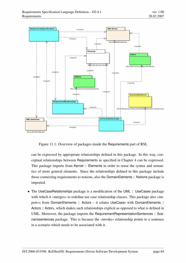
Requirements Specification Language Definition – D2.4.1Requirements
ver. 1.0028.02.2007
RequirementsSpecifications
RequirementRelationships
UseCaseRelationships
UML:Kernel
(from UMLMetaMode l)
Actors
(from RSLSyntax:DomainE lements)
UML:UseCases
(from UMLMetaModel )
Elements
(from RSLSyntax:Kerne l )
Notions
(from RSLSyn tax:DomainElements)
ScenarioSentences
(from RSLSyn tax:Requi rementRepresenta tionSentences)
« im port»
«merge»
« im port»
« im port»
« im port»« im port»
«merge»
«im port»
« im port»
« im port»
« im port»
« im port»« im port»
« im port»
« im port»
« im port»
Figure 11.1: Overview of packages inside the Requirements part of RSL
can be expressed by appropriate relationships defined in this package. In this way, con-ceptual relationships between Requirements as specified in Chapter 4 can be expressed.This package imports from Kernel :: Elements in order to reuse the syntax and seman-tics of more general elements. Since the relationships defined in this package includethose connecting requirements to notions, also the DomainElements :: Notions package isimported.
• The UseCaseRelationships package is a modification of the UML :: UseCases packagewith which it «merges» to redefine use case relationship classes. This package also «im-port»s from DomainElements :: Actors – it relates UseCases with DomainElements ::
Actors :: Actors, which makes such relationships explicit as opposed to what is defined inUML. Moreover, the package imports the RequirementRepresentationSentences :: Sce-
nariosentences package. This is because the «invoke» relationship points to a sentencein a scenario which needs to be associated with it.
IST-2006-033596 ReDSeeDS: Requirements Driven Software Development System page 64
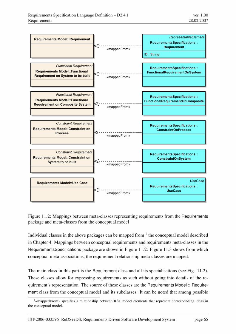
Requirements Specification Language Definition – D2.4.1Requirements
ver. 1.0028.02.2007
RepresentableElement
RequirementsSpecifications::
Requirement
ID: String
UseCase
RequirementsSpecifications::
UseCase
Requirements Model::Use Case
Requirements Model::Requirement
Constraint Requirement
Requirements Model::Constraint on
Process
Constraint Requirement
Requirements Model::Constraint on
System to be built
Functional Requirement
Requirements Model::Functional
Requirement on Composite System
Functional Requirement
Requirements Model::Functional
Requirement on System to be built
RequirementsSpecifications::
ConstraintOnProcess
RequirementsSpecifications::
ConstraintOnSystem
RequirementsSpecifications::
FunctionalRequirementOnComposite
RequirementsSpecifications::
FunctionalRequirementOnSystem
«mappedFrom»
«mappedFrom»
«mappedFrom»
«mappedFrom»
«mappedFrom»
«mappedFrom»
Figure 11.2: Mappings between meta-classes representing requirements from the Requirementspackage and meta-classes from the conceptual model
Individual classes in the above packages can be mapped from 1 the conceptual model describedin Chapter 4. Mappings between conceptual requirements and requirements meta-classes in theRequirementsSpecifications package are shown in Figure 11.2. Figure 11.3 shows from whichconceptual meta-associations, the requirement relationship meta-classes are mapped.
The main class in this part is the Requirement class and all its specialisations (see Fig. 11.2).These classes allow for expressing requirements as such without going into details of the re-quirement’s representation. The source of these classes are the Requirements Model :: Require-
ment class from the conceptual model and its subclasses. It can be noted that among possible
1«mappedFrom» specifies a relationship between RSL model elements that represent corresponding ideas inthe conceptual model.
IST-2006-033596 ReDSeeDS: Requirements Driven Software Development System page 65
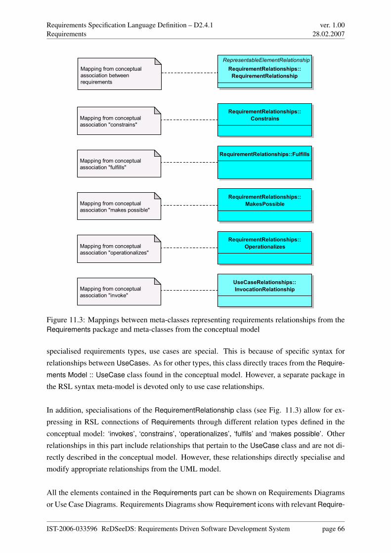
Requirements Specification Language Definition – D2.4.1Requirements
ver. 1.0028.02.2007
RepresentableElementRelationship
RequirementRelationships::
RequirementRelationship
Mapping from conceptual
association between
requirements
RequirementRelationships::
Constrains
RequirementRelationships::Fulfills
RequirementRelationships::
MakesPossible
RequirementRelationships::
Operationalizes
Mapping from conceptual
association "constrains"
Mapping from conceptual
association "fulfills"
Mapping from conceptual
association "makes possible"
Mapping from conceptual
association "operationalizes"
UseCaseRelationships::
InvocationRelationshipMapping from conceptual
association "invoke"
Figure 11.3: Mappings between meta-classes representing requirements relationships from theRequirements package and meta-classes from the conceptual model
specialised requirements types, use cases are special. This is because of specific syntax forrelationships between UseCases. As for other types, this class directly traces from the Require-
ments Model :: UseCase class found in the conceptual model. However, a separate package inthe RSL syntax meta-model is devoted only to use case relationships.
In addition, specialisations of the RequirementRelationship class (see Fig. 11.3) allow for ex-pressing in RSL connections of Requirements through different relation types defined in theconceptual model: ‘invokes’, ‘constrains’, ‘operationalizes’, ‘fulfils’ and ‘makes possible’. Otherrelationships in this part include relationships that pertain to the UseCase class and are not di-rectly described in the conceptual model. However, these relationships directly specialise andmodify appropriate relationships from the UML model.
All the elements contained in the Requirements part can be shown on Requirements Diagramsor Use Case Diagrams. Requirements Diagrams show Requirement icons with relevant Require-
IST-2006-033596 ReDSeeDS: Requirements Driven Software Development System page 66
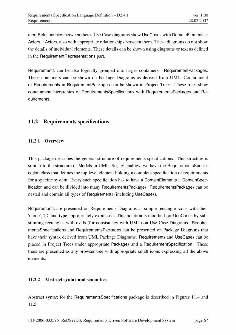
Requirements Specification Language Definition – D2.4.1Requirements
ver. 1.0028.02.2007
mentRelationships between them. Use Case diagrams show UseCases with DomainElements ::
Actors :: Actors, also with appropriate relationships between them. These diagrams do not showthe details of individual elements. These details can be shown using diagrams or text as definedin the RequirementRepresentations part.
Requirements can be also logically grouped into larger containers - RequirementPackages.These containers can be shown on Package Diagrams as derived from UML. Containmentof Requirements in RequirementPackages can be shown in Project Trees. These trees showcontainment hierarchies of RequirementsSpecifications with RequirementsPackages and Re-
quirements.
11.2 Requirements specifications
11.2.1 Overview
This package describes the general structure of requirements specifications. This structure issimilar to the structure of Models in UML. So, by analogy, we have the RequirementsSpecifi-
cation class that defines the top level element holding a complete specification of requirementsfor a specific system. Every such specification has to have a DomainElements :: DomainSpec-
ification and can be divided into many RequirementsPackages. RequirementsPackages can benested and contain all types of Requirements (including UseCases).
Requirements are presented on Requirements Diagrams as simple rectangle icons with their‘name’, ‘ID’ and type appropriately expressed. This notation is modified for UseCases by sub-stituting rectangles with ovals (for consistency with UML) on Use Case Diagrams. Require-
mentsSpecifications and RequirementsPackages can be presented on Package Diagrams thathave their syntax derived from UML Package Diagrams. Requirements and UseCases can beplaced in Project Trees under appropriate Packages and a RequirementSpecification. Thesetrees are presented as any browser tree with appropriate small icons expressing all the aboveelements.
11.2.2 Abstract syntax and semantics
Abstract syntax for the RequirementsSpecifications package is described in Figures 11.4 and11.5.
IST-2006-033596 ReDSeeDS: Requirements Driven Software Development System page 67
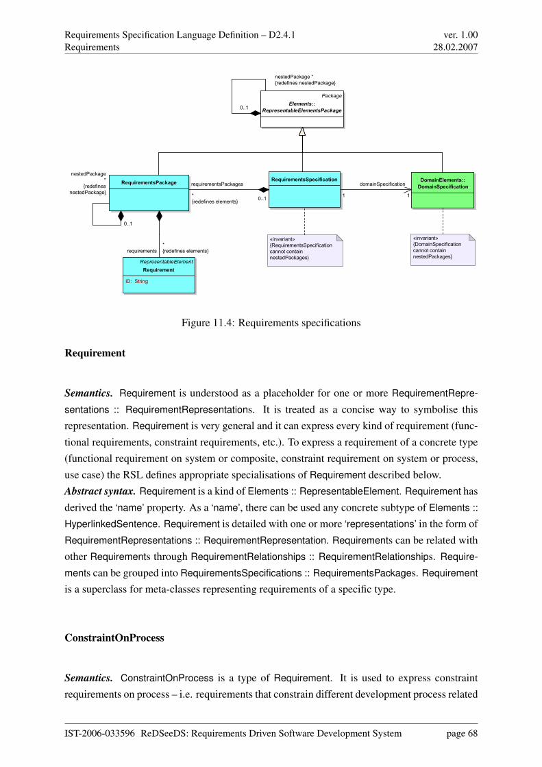
Requirements Specification Language Definition – D2.4.1Requirements
ver. 1.0028.02.2007
RequirementsSpecificationRequirementsPackage
RepresentableElement
Requirement
ID: String
DomainElements::
DomainSpecification
Package
Elements::
RepresentableElementsPackage
«invariant»
{RequirementsSpecification
cannot contain
nestedPackages}
«invariant»
{DomainSpecification
cannot contain
nestedPackages}
1
domainSpecification
1
requirementsPackages
*
{redefines elements}0..1
nestedPackage
*
{redefines
nestedPackage}
0..1
requirements
*
{redefines elements}
nestedPackage *
{redefines nestedPackage}
0..1
Figure 11.4: Requirements specifications
Requirement
Semantics. Requirement is understood as a placeholder for one or more RequirementRepre-
sentations :: RequirementRepresentations. It is treated as a concise way to symbolise thisrepresentation. Requirement is very general and it can express every kind of requirement (func-tional requirements, constraint requirements, etc.). To express a requirement of a concrete type(functional requirement on system or composite, constraint requirement on system or process,use case) the RSL defines appropriate specialisations of Requirement described below.Abstract syntax. Requirement is a kind of Elements :: RepresentableElement. Requirement hasderived the ‘name’ property. As a ‘name’, there can be used any concrete subtype of Elements ::
HyperlinkedSentence. Requirement is detailed with one or more ‘representations’ in the form ofRequirementRepresentations :: RequirementRepresentation. Requirements can be related withother Requirements through RequirementRelationships :: RequirementRelationships. Require-
ments can be grouped into RequirementsSpecifications :: RequirementsPackages. Requirement
is a superclass for meta-classes representing requirements of a specific type.
ConstraintOnProcess
Semantics. ConstraintOnProcess is a type of Requirement. It is used to express constraintrequirements on process – i.e. requirements that constrain different development process related
IST-2006-033596 ReDSeeDS: Requirements Driven Software Development System page 68
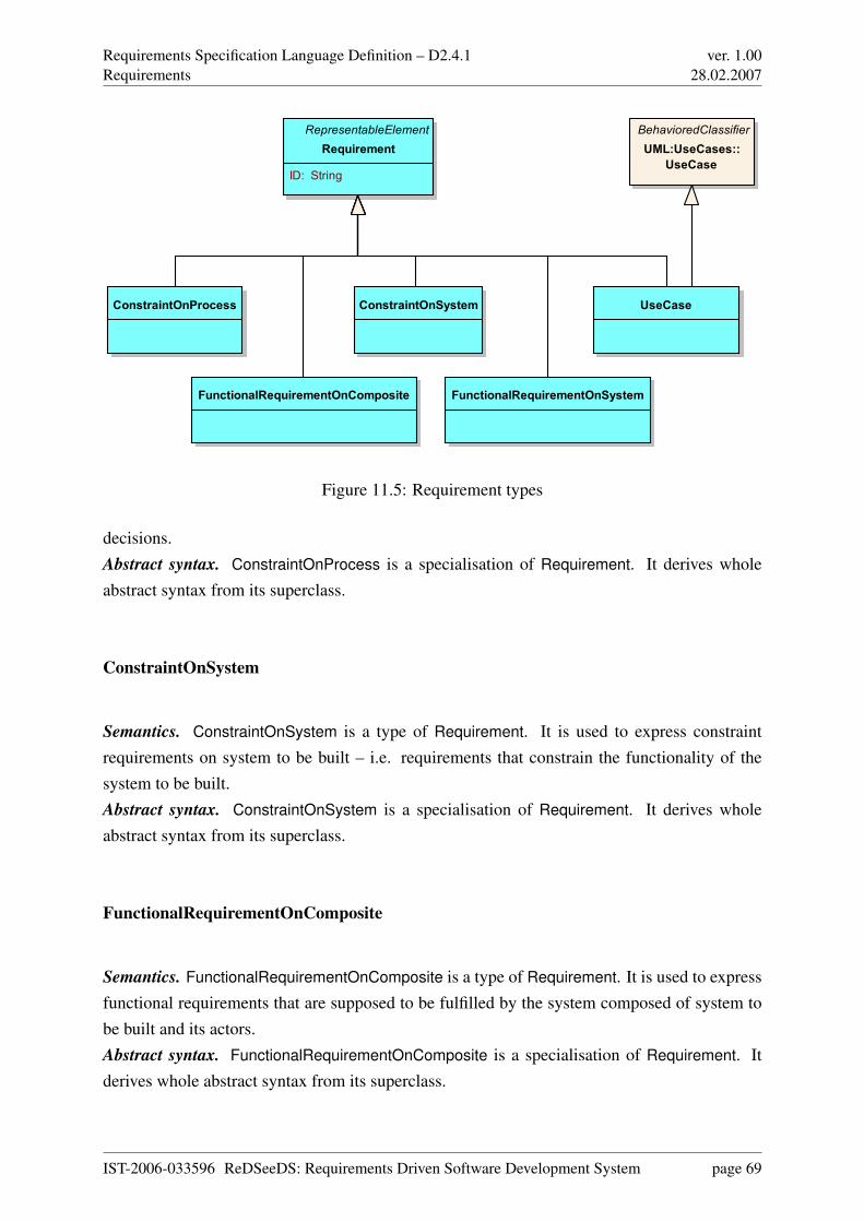
Requirements Specification Language Definition – D2.4.1Requirements
ver. 1.0028.02.2007
RepresentableElement
Requirement
ID: String
UseCaseConstraintOnProcess ConstraintOnSystem
FunctionalRequirementOnComposite FunctionalRequirementOnSystem
BehavioredClassifier
UML:UseCases::
UseCase
Figure 11.5: Requirement types
decisions.Abstract syntax. ConstraintOnProcess is a specialisation of Requirement. It derives wholeabstract syntax from its superclass.
ConstraintOnSystem
Semantics. ConstraintOnSystem is a type of Requirement. It is used to express constraintrequirements on system to be built – i.e. requirements that constrain the functionality of thesystem to be built.Abstract syntax. ConstraintOnSystem is a specialisation of Requirement. It derives wholeabstract syntax from its superclass.
FunctionalRequirementOnComposite
Semantics. FunctionalRequirementOnComposite is a type of Requirement. It is used to expressfunctional requirements that are supposed to be fulfilled by the system composed of system tobe built and its actors.Abstract syntax. FunctionalRequirementOnComposite is a specialisation of Requirement. Itderives whole abstract syntax from its superclass.
IST-2006-033596 ReDSeeDS: Requirements Driven Software Development System page 69
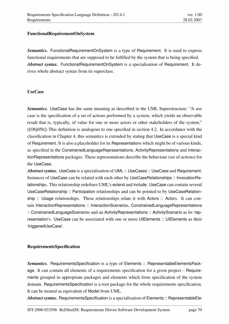
Requirements Specification Language Definition – D2.4.1Requirements
ver. 1.0028.02.2007
FunctionalRequirementOnSystem
Semantics. FunctionalRequirementOnSystem is a type of Requirement. It is used to expressfunctional requirements that are supposed to be fulfilled by the system that is being specified.Abstract syntax. FunctionalRequirementOnSystem is a specialisation of Requirement. It de-rives whole abstract syntax from its superclass.
UseCase
Semantics. UseCase has the same meaning as described in the UML Superstructure: “A usecase is the specification of a set of actions performed by a system, which yields an observableresult that is, typically, of value for one or more actors or other stakeholders of the system.”([Obj05b]) This definition is analogous to one specified in section 4.2. In accordance with theclassification in Chapter 4, this semantics is extended by stating that UseCase is a special kindof Requirement. It is also a placeholder for its Representations which might be of various kinds,as specified in the ConstrainedLanguageRepresentations, ActivityRepresentations and Interac-
tionRepresentations packages. These representations describe the behaviour (set of actions) forthe UseCase.Abstract syntax. UseCase is a specialisation of UML :: UseCases :: UseCase and Requirement.Instances of UseCase can be related with each other by UseCaseRelationships :: InvocationRe-
lationships. This relationship redefines UML’s extend and include. UseCase can contain severalUseCaseRelationship :: Participation relationships and can be pointed to by UseCaseRelation-
ship :: Usage relationships. These relationships relate it with Actors :: Actors. It can con-tain InteractionRepresentations :: InteractionScenarios, ConstrainedLanguageRepresentations
:: ConstrainedLanguageScenarios and an ActivityRepresentations :: ActivityScenario as its ‘rep-
resentation’s. UseCase can be associated with one or more UIElements :: UIElements as their‘triggeredUseCase’.
RequirementsSpecification
Semantics. RequirementsSpecification is a type of Elements :: RepresentableElementsPack-
age. It can contain all elements of a requirements specification for a given project – Require-
ments grouped in appropriate packages and elements which form specification of the systemdomain. RequirementsSpecification is a root package for the whole requirements specification.It can be treated as equivalent of Model from UML.Abstract syntax. RequirementsSpecification is a specialisation of Elements :: RepresentableEle-
IST-2006-033596 ReDSeeDS: Requirements Driven Software Development System page 70
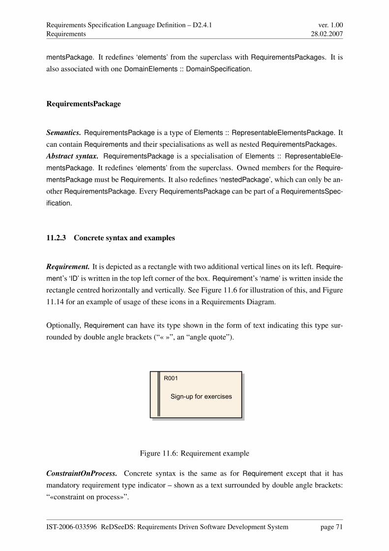
Requirements Specification Language Definition – D2.4.1Requirements
ver. 1.0028.02.2007
mentsPackage. It redefines ‘elements’ from the superclass with RequirementsPackages. It isalso associated with one DomainElements :: DomainSpecification.
RequirementsPackage
Semantics. RequirementsPackage is a type of Elements :: RepresentableElementsPackage. Itcan contain Requirements and their specialisations as well as nested RequirementsPackages.Abstract syntax. RequirementsPackage is a specialisation of Elements :: RepresentableEle-
mentsPackage. It redefines ‘elements’ from the superclass. Owned members for the Require-
mentsPackage must be Requirements. It also redefines ‘nestedPackage’, which can only be an-other RequirementsPackage. Every RequirementsPackage can be part of a RequirementsSpec-
ification.
11.2.3 Concrete syntax and examples
Requirement. It is depicted as a rectangle with two additional vertical lines on its left. Require-
ment’s ‘ID’ is written in the top left corner of the box. Requirement’s ‘name’ is written inside therectangle centred horizontally and vertically. See Figure 11.6 for illustration of this, and Figure11.14 for an example of usage of these icons in a Requirements Diagram.
Optionally, Requirement can have its type shown in the form of text indicating this type sur-rounded by double angle brackets (“« »”, an “angle quote”).
Sign-up for exercises
R001
Figure 11.6: Requirement example
ConstraintOnProcess. Concrete syntax is the same as for Requirement except that it hasmandatory requirement type indicator – shown as a text surrounded by double angle brackets:“«constraint on process»”.
IST-2006-033596 ReDSeeDS: Requirements Driven Software Development System page 71
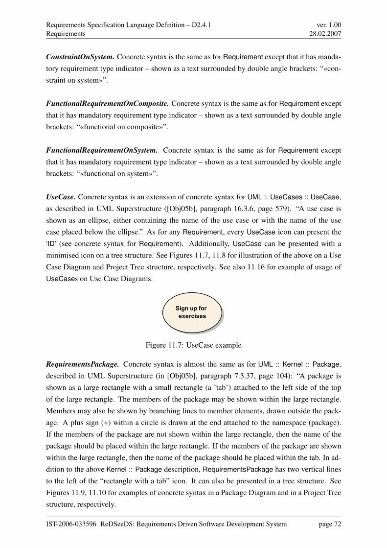
Requirements Specification Language Definition – D2.4.1Requirements
ver. 1.0028.02.2007
ConstraintOnSystem. Concrete syntax is the same as for Requirement except that it has manda-tory requirement type indicator – shown as a text surrounded by double angle brackets: “«con-straint on system»”.
FunctionalRequirementOnComposite. Concrete syntax is the same as for Requirement exceptthat it has mandatory requirement type indicator – shown as a text surrounded by double anglebrackets: “«functional on composite»”.
FunctionalRequirementOnSystem. Concrete syntax is the same as for Requirement exceptthat it has mandatory requirement type indicator – shown as a text surrounded by double anglebrackets: “«functional on system»”.
UseCase. Concrete syntax is an extension of concrete syntax for UML :: UseCases :: UseCase,as described in UML Superstructure ([Obj05b], paragraph 16.3.6, page 579). “A use case isshown as an ellipse, either containing the name of the use case or with the name of the usecase placed below the ellipse.” As for any Requirement, every UseCase icon can present the‘ID’ (see concrete syntax for Requirement). Additionally, UseCase can be presented with aminimised icon on a tree structure. See Figures 11.7, 11.8 for illustration of the above on a UseCase Diagram and Project Tree structure, respectively. See also 11.16 for example of usage ofUseCases on Use Case Diagrams.
Sign up for
exercises
Figure 11.7: UseCase example
RequirementsPackage. Concrete syntax is almost the same as for UML :: Kernel :: Package,described in UML Superstructure (in [Obj05b], paragraph 7.3.37, page 104): “A package isshown as a large rectangle with a small rectangle (a ’tab’) attached to the left side of the topof the large rectangle. The members of the package may be shown within the large rectangle.Members may also be shown by branching lines to member elements, drawn outside the pack-age. A plus sign (+) within a circle is drawn at the end attached to the namespace (package).If the members of the package are not shown within the large rectangle, then the name of thepackage should be placed within the large rectangle. If the members of the package are shownwithin the large rectangle, then the name of the package should be placed within the tab. In ad-dition to the above Kernel :: Package description, RequirementsPackage has two vertical linesto the left of the “rectangle with a tab” icon. It can also be presented in a tree structure. SeeFigures 11.9, 11.10 for examples of concrete syntax in a Package Diagram and in a Project Treestructure, respectively.
IST-2006-033596 ReDSeeDS: Requirements Driven Software Development System page 72
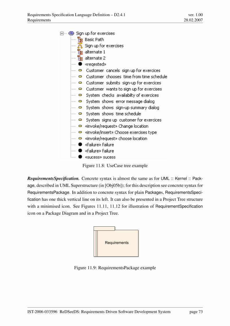
Requirements Specification Language Definition – D2.4.1Requirements
ver. 1.0028.02.2007
Figure 11.8: UseCase tree example
RequirementsSpecification. Concrete syntax is almost the same as for UML :: Kernel :: Pack-
age, described in UML Superstructure (in [Obj05b]); for this description see concrete syntax forRequirementsPackage. In addition to concrete syntax for plain Packages, RequirementsSpeci-
fication has one thick vertical line on its left. It can also be presented in a Project Tree structurewith a minimised icon. See Figures 11.11, 11.12 for illustration of RequirementSpecification
icon on a Package Diagram and in a Project Tree.
Requirements
Figure 11.9: RequirementsPackage example
IST-2006-033596 ReDSeeDS: Requirements Driven Software Development System page 73
Requirements Specification Language Definition – D2.4.1Requirements
ver. 1.0028.02.2007
Figure 11.10: RequirementsPackage tree example
Requirements specification
Figure 11.11: RequirementsSpecification example
11.3 Requirement relationships
11.3.1 Overview
This package describes relationships of different types between Requirements. Standard re-lationships, as specified in the conceptual model are defined here. Moreover, a relationshipbetween a Requirement and Notions found in the domain specification are made available.
In general, relationships between Requirements are presented on Requirements Diagrams asdashed arrows with appropriate relationship type expressed through its name in angle brackets.
11.3.2 Abstract syntax and semantics
Abstract syntax for the RequirementRelationships package is described in Figure 11.13.
Figure 11.12: RequirementsSpecification tree example
IST-2006-033596 ReDSeeDS: Requirements Driven Software Development System page 74
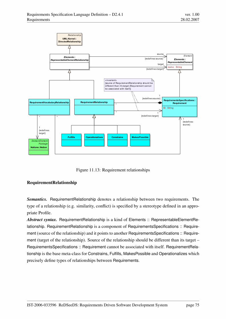
Requirements Specification Language Definition – D2.4.1Requirements
ver. 1.0028.02.2007
RequirementsSpecifications::Requirement
ID: String
RelationshipUML:Kernel::
DirectedRelationship
RequirementRelationship
«invariant»{source of Requirem entRelationship should be d i fferent than i t's target (Requirem ent cannot be associated wi th i tse l f)}
Elements::RepresentableElementRelationship
Fulfills Operationalises Constrains MakesPossible
ElementElements::
RepresentableElement
nam e: String
RequirementVocabularyRelationship
DomainElementPackage
Notions::Notion
*
1{redefines source}
*1{redefinessource}
* 1{redefines target}
source
{redefines source}
target
{redefines target}
*
1{redefinestarget}
Figure 11.13: Requirement relationships
RequirementRelationship
Semantics. RequirementRelationship denotes a relationship between two requirements. Thetype of a relationship (e.g. similarity, conflict) is specified by a stereotype defined in an appro-priate Profile.Abstract syntax. RequirementRelationship is a kind of Elements :: RepresentableElementRe-
lationship. RequirementRelationship is a component of RequirementsSpecifications :: Require-
ment (source of the relationship) and it points to another RequirementsSpecifications :: Require-
ment (target of the relationship). Source of the relationship should be different than its target –RequirementsSpecifications :: Requirement cannot be associated with itself. RequirementRela-
tionship is the base meta-class for Constrains, Fulfills, MakesPossible and Operationalizes whichprecisely define types of relationships between Requirements.
IST-2006-033596 ReDSeeDS: Requirements Driven Software Development System page 75
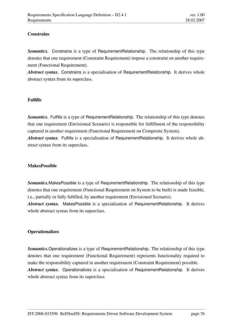
Requirements Specification Language Definition – D2.4.1Requirements
ver. 1.0028.02.2007
Constrains
Semantics. Constrains is a type of RequirementRelationship. The relationship of this typedenotes that one requirement (Constraint Requirement) impose a constraint on another require-ment (Functional Requirement).Abstract syntax. Constrains is a specialisation of RequirementRelationship. It derives wholeabstract syntax from its superclass.
Fulfills
Semantics. Fulfills is a type of RequirementRelationship. The relationship of this type denotesthat one requirement (Envisioned Scenario) is responsible for fulfillment of the responsibilitycaptured in another requirement (Functional Requirement on Composite System).Abstract syntax. Fulfills is a specialisation of RequirementRelationship. It derives whole ab-stract syntax from its superclass.
MakesPossible
Semantics.MakesPossible is a type of RequirementRelationship. The relationship of this typedenotes that one requirement (Functional Requirement on System to be built) is made feasible,i.e., partially or fully fulfilled, by another requirement (Envisioned Scenario).Abstract syntax. MakesPossible is a specialisation of RequirementRelationship. It deriveswhole abstract syntax from its superclass.
Operationalizes
Semantics.Operationalizes is a type of RequirementRelationship. The relationship of this typedenotes that one requirement (Functional Requirement) represents functionality required tomake the responsibility captured in another requirement (Constraint Requirement) possible.Abstract syntax. Operationalizes is a specialisation of RequirementRelationship. It deriveswhole abstract syntax from its superclass.
IST-2006-033596 ReDSeeDS: Requirements Driven Software Development System page 76
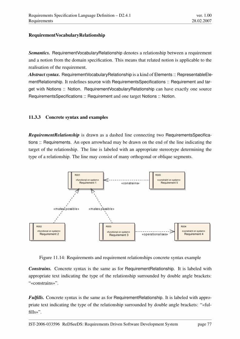
Requirements Specification Language Definition – D2.4.1Requirements
ver. 1.0028.02.2007
RequirementVocabularyRelationship
Semantics. RequirementVocabularyRelationship denotes a relationship between a requirementand a notion from the domain specification. This means that related notion is applicable to therealisation of the requirement.Abstract syntax. RequirementVocabularyRelationship is a kind of Elements :: RepresentableEle-
mentRelationship. It redefines source with RequirementsSpecifications :: Requirement and tar-
get with Notions :: Notion. RequirementVocabularyRelationship can have exactly one sourceRequirementsSpecifications :: Requirement and one target Notions :: Notion.
11.3.3 Concrete syntax and examples
RequirementRelationship is drawn as a dashed line connecting two RequirementsSpecifica-
tions :: Requirements. An open arrowhead may be drawn on the end of the line indicating thetarget of the relationship. The line is labeled with an appropriate stereotype determining thetype of a relationship. The line may consist of many orthogonal or oblique segments.
«operational ises»
«m akes possib le» «m akes possib le»
«constrains»
R001 R005
R002 R003 R004
«functional on system» Requirement 1
«constraint on system» Requirement 5
«functional on system» Requirement 2
«functional on system» Requirement 3
«constraint on system» Requirement 4
Figure 11.14: Requirements and requirement relationships concrete syntax example
Constrains. Concrete syntax is the same as for RequirementRelationship. It is labeled withappropriate text indicating the type of the relationship surrounded by double angle brackets:“«constrains»”.
Fulfills. Concrete syntax is the same as for RequirementRelationship. It is labeled with appro-priate text indicating the type of the relationship surrounded by double angle brackets: “«ful-fills»”.
IST-2006-033596 ReDSeeDS: Requirements Driven Software Development System page 77
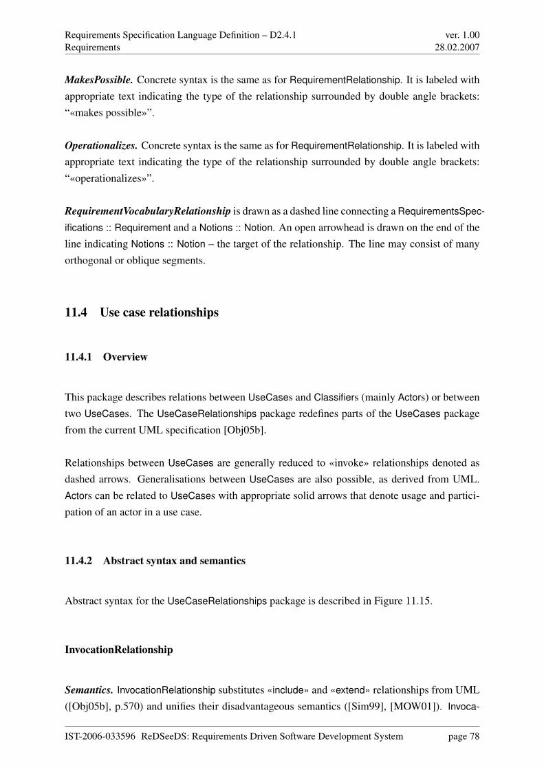
Requirements Specification Language Definition – D2.4.1Requirements
ver. 1.0028.02.2007
MakesPossible. Concrete syntax is the same as for RequirementRelationship. It is labeled withappropriate text indicating the type of the relationship surrounded by double angle brackets:“«makes possible»”.
Operationalizes. Concrete syntax is the same as for RequirementRelationship. It is labeled withappropriate text indicating the type of the relationship surrounded by double angle brackets:“«operationalizes»”.
RequirementVocabularyRelationship is drawn as a dashed line connecting a RequirementsSpec-
ifications :: Requirement and a Notions :: Notion. An open arrowhead is drawn on the end of theline indicating Notions :: Notion – the target of the relationship. The line may consist of manyorthogonal or oblique segments.
11.4 Use case relationships
11.4.1 Overview
This package describes relations between UseCases and Classifiers (mainly Actors) or betweentwo UseCases. The UseCaseRelationships package redefines parts of the UseCases packagefrom the current UML specification [Obj05b].
Relationships between UseCases are generally reduced to «invoke» relationships denoted asdashed arrows. Generalisations between UseCases are also possible, as derived from UML.Actors can be related to UseCases with appropriate solid arrows that denote usage and partici-pation of an actor in a use case.
11.4.2 Abstract syntax and semantics
Abstract syntax for the UseCaseRelationships package is described in Figure 11.15.
InvocationRelationship
Semantics. InvocationRelationship substitutes «include» and «extend» relationships from UML([Obj05b], p.570) and unifies their disadvantageous semantics ([Sim99], [MOW01]). Invoca-
IST-2006-033596 ReDSeeDS: Requirements Driven Software Development System page 78
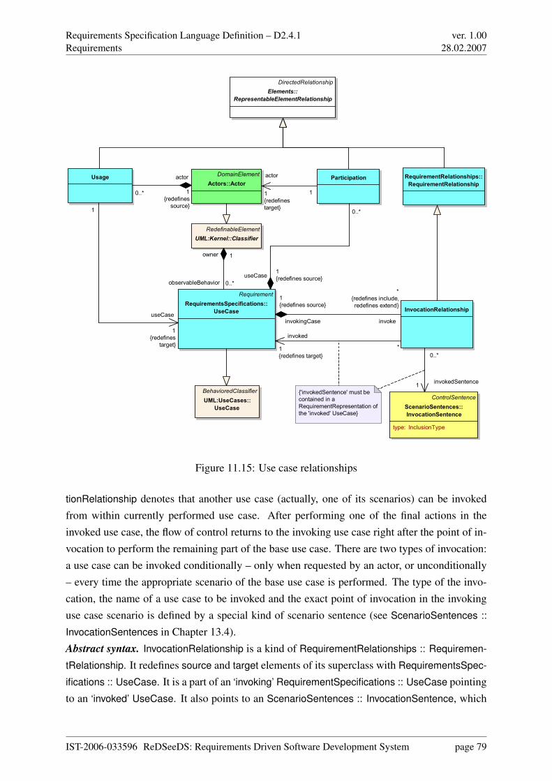
Requirements Specification Language Definition – D2.4.1Requirements
ver. 1.0028.02.2007
Requirement
RequirementsSpecifications::
UseCase
Participation
InvocationRelationship
Usage
ControlSentence
ScenarioSentences::
InvocationSentence
type: InclusionType
DomainElement
Actors::Actor
RedefinableElement
UML:Kernel::Classifier
{'invokedSentence' must be
contained in a
RequirementRepresentation of
the 'invoked' UseCase}
BehavioredClassifier
UML:UseCases::
UseCase
DirectedRelationship
Elements::
RepresentableElementRelationship
RequirementRelationships::
RequirementRelationship
observableBehavior 0..*
owner 1
0..*
useCase1
{redefines source}
1
actor
1
{redefines
target}
*
invoked
1
{redefines target}
invoke
*
{redefines include,
redefines extend}
invokingCase
1
{redefines source}
0..*
invokedSentence1
1
useCase
1
{redefines
target}
0..*
actor
1
{redefines
source}
Figure 11.15: Use case relationships
tionRelationship denotes that another use case (actually, one of its scenarios) can be invokedfrom within currently performed use case. After performing one of the final actions in theinvoked use case, the flow of control returns to the invoking use case right after the point of in-vocation to perform the remaining part of the base use case. There are two types of invocation:a use case can be invoked conditionally – only when requested by an actor, or unconditionally– every time the appropriate scenario of the base use case is performed. The type of the invo-cation, the name of a use case to be invoked and the exact point of invocation in the invokinguse case scenario is defined by a special kind of scenario sentence (see ScenarioSentences ::
InvocationSentences in Chapter 13.4).Abstract syntax. InvocationRelationship is a kind of RequirementRelationships :: Requiremen-
tRelationship. It redefines source and target elements of its superclass with RequirementsSpec-
ifications :: UseCase. It is a part of an ‘invoking’ RequirementSpecifications :: UseCase pointingto an ‘invoked’ UseCase. It also points to an ScenarioSentences :: InvocationSentence, which
IST-2006-033596 ReDSeeDS: Requirements Driven Software Development System page 79
Requirements Specification Language Definition – D2.4.1Requirements
ver. 1.0028.02.2007
must be contained in a RequirementRepresentations :: RequirementRepresentation of the ‘in-
voked’ UseCase.
Usage
Semantics. Usage indicates possibility for an Actors :: Actor to initiate a particular UseCase
performance directly as a primary actor (the one that expects to reach the use case’s goal).Abstract syntax. Usage is a kind of RequirementRelationships :: RequirementRelationship. Itis a component of an Actor and points to a RequirementSpecifications :: UseCase.
Participation
Semantics. Participation indicates possibility for an Actor to participate as a secondary actor inthe execution of a particular UseCase.Abstract syntax. Participation is a kind of RequirementRelationships :: RequirementRelation-
ship. It is a component of a RequirementSpecifications :: UseCase and points to an Actor.
11.4.3 Concrete syntax and examples
InvocationRelationship. It can be shown similarly to a UML Dependency relationship betweenRequirementSpecifications :: UseCases with an «invoke» stereotype and an open arrowheaddenoting navigability on the end of the ‘invoked’ RequirementSpecifications :: UseCase (seeFigure 11.16).
Usage. It’s concrete syntax is a solid line between an Actor and a RequirementSpecifications ::
UseCase and an arrowhead on the side of the UseCase (see Figure 11.16). This arrow can beappended with a «use» UML-like stereotype.
Participation’s concrete syntax is a solid line between a RequirementSpecifications :: UseCase
and an Actors :: Actor and an arrowhead on the side of the Actor (see Figure 11.16). This arrowcan be appended with a «participate» UML-like stereotype.
IST-2006-033596 ReDSeeDS: Requirements Driven Software Development System page 80
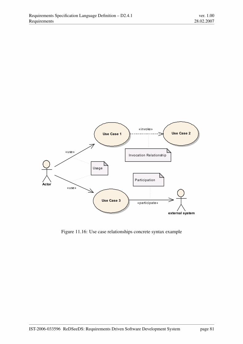
Requirements Specification Language Definition – D2.4.1Requirements
ver. 1.0028.02.2007
Actor
Use Case 1 Use Case 2
Use Case 3
external system
Invocation Relationship
Participation
Usage
«use»
«participate»
«invoke»
«use»
Figure 11.16: Use case relationships concrete syntax example
IST-2006-033596 ReDSeeDS: Requirements Driven Software Development System page 81
Requirements Specification Language Definition – D2.4.1Requirement representations
ver. 1.0028.02.2007
Chapter 12
Requirement representations
12.1 Overview
In the RequirementRepresentations part we describe how our language defines requirementrepresentations and present differences between various requirement representations. As statedin Part I, requirements can have descriptive representations (natural or constrained language) orschematic representations (model-based). Language users will typically use elements from thispart to describe the contents of individual requirements using the notations chosen from thoseavailable in the language. Requirement representations are tightly bound to the appropriaterequirements they represent. Particular representation depends highly on the requirement type,as specified in the Requirements part.
The specification in this part contains five packages, as shown in Figures 12.1 and 12.2 (markedin blue on colour print-outs, excluding RequirementSpecifications belonging to the previouspart).
• The RequirementRepresentations package contains all the general constructs needed topolymorphically represent differing requirement representations. It «import»s from theRequirementsSpecifications package to relate representations with appropriate require-ments defined there. It also «import»s the Elements package, for RequirementRepresen-
tation is a subtype of ElementRepresentation. As such the RequirementRepresentations
package gives access to the RequirementsSpecifications package. The RequirementRep-
resentations package describes a general way of representing Requirements: every Re-
quirementRepresentation is a component for its Requirement.
IST-2006-033596 ReDSeeDS: Requirements Driven Software Development System page 82
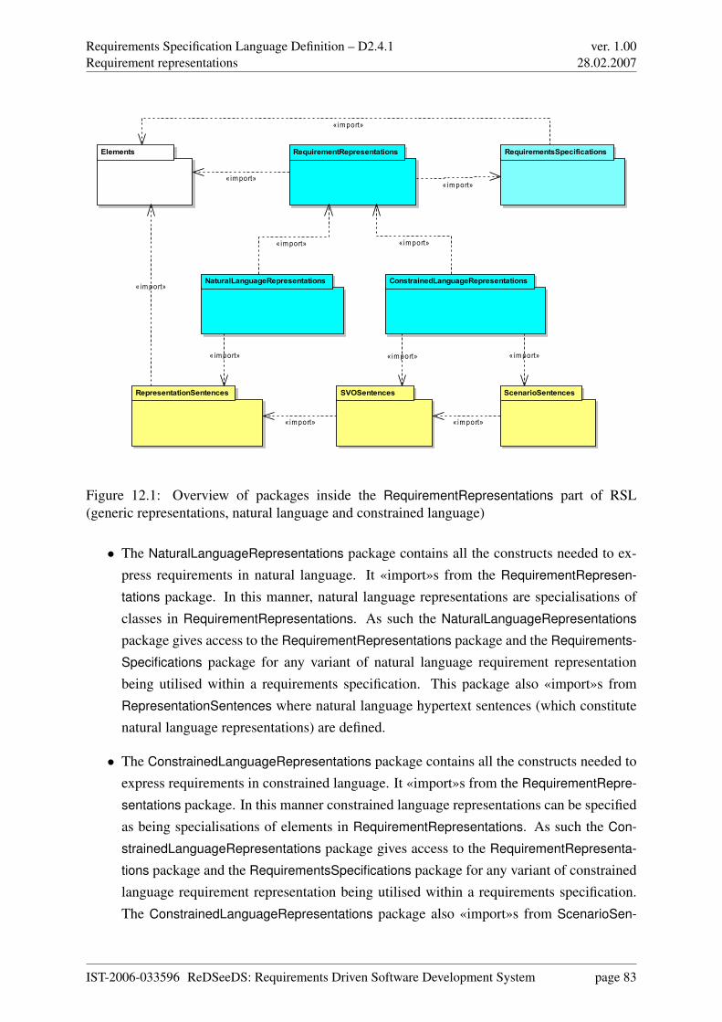
Requirements Specification Language Definition – D2.4.1Requirement representations
ver. 1.0028.02.2007
NaturalLanguageRepresentations ConstrainedLanguageRepresentations
RequirementRepresentationsElements
RepresentationSentences SVOSentences ScenarioSentences
RequirementsSpecifications
«import»
«import»«import»
«import»
« import»
«import»
«import»
«import»
«import»
«import»«import»
Figure 12.1: Overview of packages inside the RequirementRepresentations part of RSL(generic representations, natural language and constrained language)
• The NaturalLanguageRepresentations package contains all the constructs needed to ex-press requirements in natural language. It «import»s from the RequirementRepresen-
tations package. In this manner, natural language representations are specialisations ofclasses in RequirementRepresentations. As such the NaturalLanguageRepresentations
package gives access to the RequirementRepresentations package and the Requirements-
Specifications package for any variant of natural language requirement representationbeing utilised within a requirements specification. This package also «import»s fromRepresentationSentences where natural language hypertext sentences (which constitutenatural language representations) are defined.
• The ConstrainedLanguageRepresentations package contains all the constructs needed toexpress requirements in constrained language. It «import»s from the RequirementRepre-
sentations package. In this manner constrained language representations can be specifiedas being specialisations of elements in RequirementRepresentations. As such the Con-
strainedLanguageRepresentations package gives access to the RequirementRepresenta-
tions package and the RequirementsSpecifications package for any variant of constrainedlanguage requirement representation being utilised within a requirements specification.The ConstrainedLanguageRepresentations package also «import»s from ScenarioSen-
IST-2006-033596 ReDSeeDS: Requirements Driven Software Development System page 83
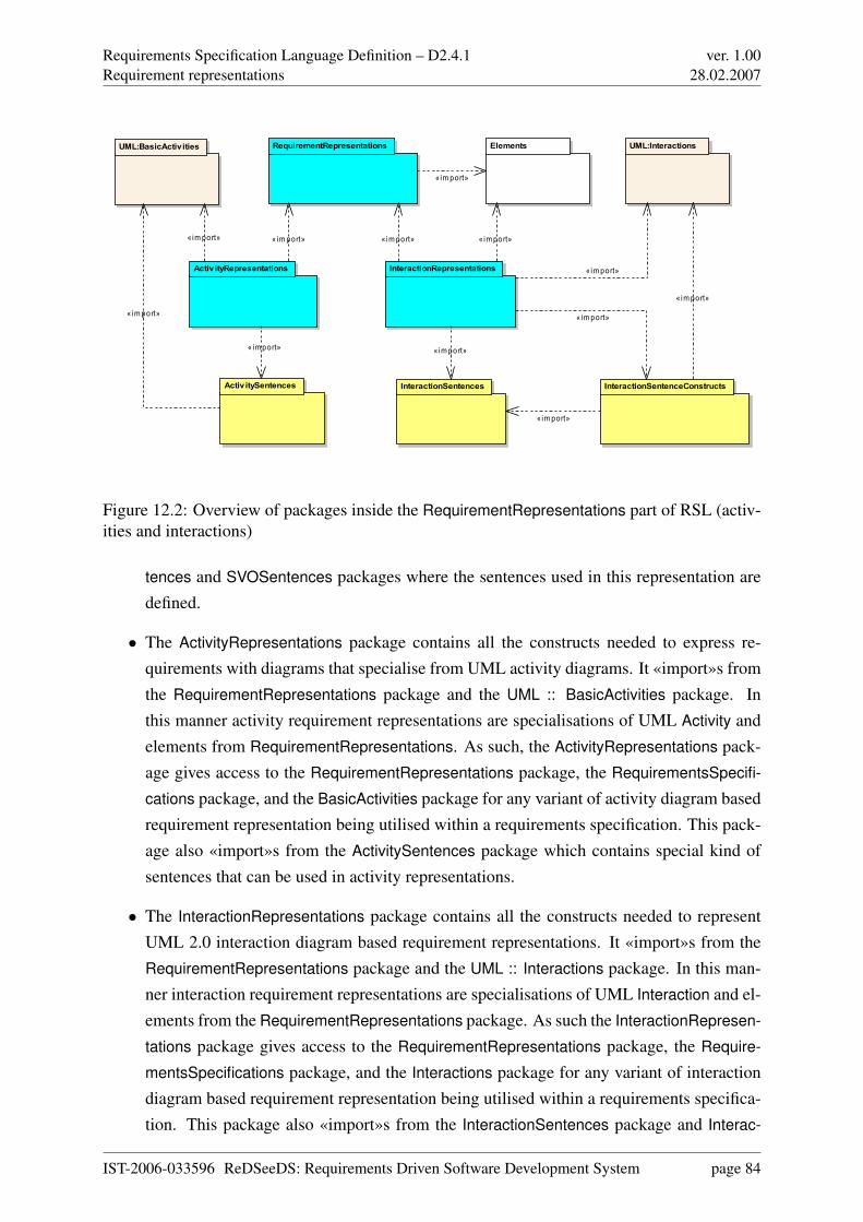
Requirements Specification Language Definition – D2.4.1Requirement representations
ver. 1.0028.02.2007
ActivityRepresentations
UML:BasicActivities UML:Interactions
InteractionRepresentations
RequirementRepresentations Elements
InteractionSentencesActivitySentences InteractionSentenceConstructs
«import»
« import» « import»
« im port»
« im port»
« import»« im port» « im port»
« import»
« import»
« import»
« im port»
Figure 12.2: Overview of packages inside the RequirementRepresentations part of RSL (activ-ities and interactions)
tences and SVOSentences packages where the sentences used in this representation aredefined.
• The ActivityRepresentations package contains all the constructs needed to express re-quirements with diagrams that specialise from UML activity diagrams. It «import»s fromthe RequirementRepresentations package and the UML :: BasicActivities package. Inthis manner activity requirement representations are specialisations of UML Activity andelements from RequirementRepresentations. As such, the ActivityRepresentations pack-age gives access to the RequirementRepresentations package, the RequirementsSpecifi-
cations package, and the BasicActivities package for any variant of activity diagram basedrequirement representation being utilised within a requirements specification. This pack-age also «import»s from the ActivitySentences package which contains special kind ofsentences that can be used in activity representations.
• The InteractionRepresentations package contains all the constructs needed to representUML 2.0 interaction diagram based requirement representations. It «import»s from theRequirementRepresentations package and the UML :: Interactions package. In this man-ner interaction requirement representations are specialisations of UML Interaction and el-ements from the RequirementRepresentations package. As such the InteractionRepresen-
tations package gives access to the RequirementRepresentations package, the Require-
mentsSpecifications package, and the Interactions package for any variant of interactiondiagram based requirement representation being utilised within a requirements specifica-tion. This package also «import»s from the InteractionSentences package and Interac-
IST-2006-033596 ReDSeeDS: Requirements Driven Software Development System page 84
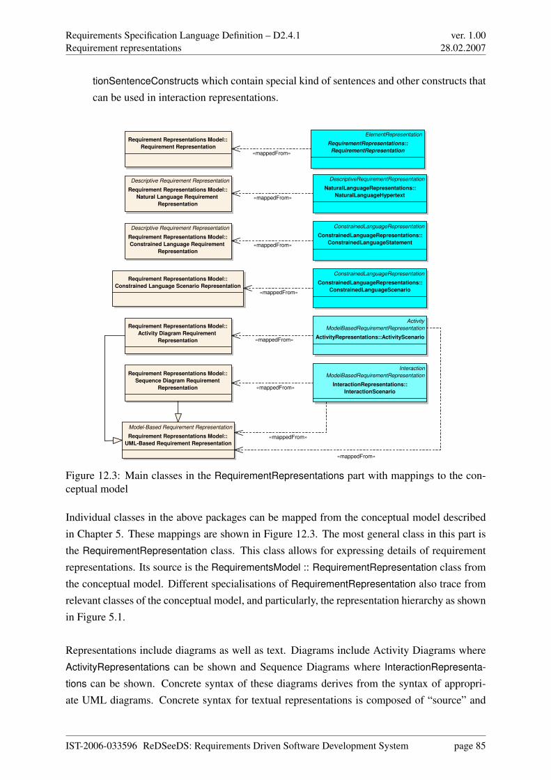
Requirements Specification Language Definition – D2.4.1Requirement representations
ver. 1.0028.02.2007
tionSentenceConstructs which contain special kind of sentences and other constructs thatcan be used in interaction representations.
Activity
ModelBasedRequirementRepresentation
ActivityRepresentations::ActivityScenario
Interaction
ModelBasedRequirementRepresentation
InteractionRepresentations::
InteractionScenario
ConstrainedLanguageRepresentation
ConstrainedLanguageRepresentations::
ConstrainedLanguageScenario
DescriptiveRequirementRepresentation
NaturalLanguageRepresentations::
NaturalLanguageHypertext
ConstrainedLanguageRepresentation
ConstrainedLanguageRepresentations::
ConstrainedLanguageStatement
ElementRepresentation
RequirementRepresentations::
RequirementRepresentation
Requirement Representations Model::
Activity Diagram Requirement
Representation
Descriptive Requirement Representation
Requirement Representations Model::
Natural Language Requirement
Representation
Requirement Representations Model::
Constrained Language Scenario Representation
Descriptive Requirement Representation
Requirement Representations Model::
Constrained Language Requirement
Representation
Requirement Representations Model::
Sequence Diagram Requirement
Representation
Requirement Representations Model::
Requirement Representation
Model-Based Requirement Representation
Requirement Representations Model::
UML-Based Requirement Representation
«mappedFrom»
«mappedFrom»
«mappedFrom»
«mappedFrom»
«mappedFrom»
«mappedFrom»
«mappedFrom»
«mappedFrom»
Figure 12.3: Main classes in the RequirementRepresentations part with mappings to the con-ceptual model
Individual classes in the above packages can be mapped from the conceptual model describedin Chapter 5. These mappings are shown in Figure 12.3. The most general class in this part isthe RequirementRepresentation class. This class allows for expressing details of requirementrepresentations. Its source is the RequirementsModel :: RequirementRepresentation class fromthe conceptual model. Different specialisations of RequirementRepresentation also trace fromrelevant classes of the conceptual model, and particularly, the representation hierarchy as shownin Figure 5.1.
Representations include diagrams as well as text. Diagrams include Activity Diagrams whereActivityRepresentations can be shown and Sequence Diagrams where InteractionRepresenta-
tions can be shown. Concrete syntax of these diagrams derives from the syntax of appropri-ate UML diagrams. Concrete syntax for textual representations is composed of “source” and
IST-2006-033596 ReDSeeDS: Requirements Driven Software Development System page 85
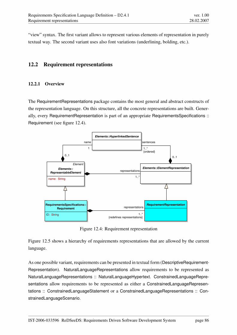
Requirements Specification Language Definition – D2.4.1Requirement representations
ver. 1.0028.02.2007
“view” syntax. The first variant allows to represent various elements of representation in purelytextual way. The second variant uses also font variations (underlining, bolding, etc.).
12.2 Requirement representations
12.2.1 Overview
The RequirementRepresentations package contains the most general and abstract constructs ofthe representation language. On this structure, all the concrete representations are built. Gener-ally, every RequirementRepresentation is part of an appropriate RequirementsSpecifications ::
Requirement (see figure 12.4).
RequirementsSpecifications::
Requirement
ID: String
Elements::HyperlinkedSentence
RequirementRepresentation
Elements::ElementRepresentation
Element
Elements::
RepresentableElement
name: String
representations
1..*{redefines representations}
sentences
1..*{ordered}
0..1
name
1
0..1
representations
1..*
Figure 12.4: Requirement representation
Figure 12.5 shows a hierarchy of requirements representations that are allowed by the currentlanguage.
As one possible variant, requirements can be presented in textual form (DescriptiveRequirement-
Representation). NaturalLanguageRepresentations allow requirements to be represented asNaturalLanguageRepresentations :: NaturalLanguageHypertext. ConstrainedLanguageRepre-
sentations allow requirements to be represented as either a ConstrainedLanguageRepresen-
tations :: ConstrainedLanguageStatement or a ConstrainedLanguageRepresentations :: Con-
strainedLanguageScenario.
IST-2006-033596 ReDSeeDS: Requirements Driven Software Development System page 86
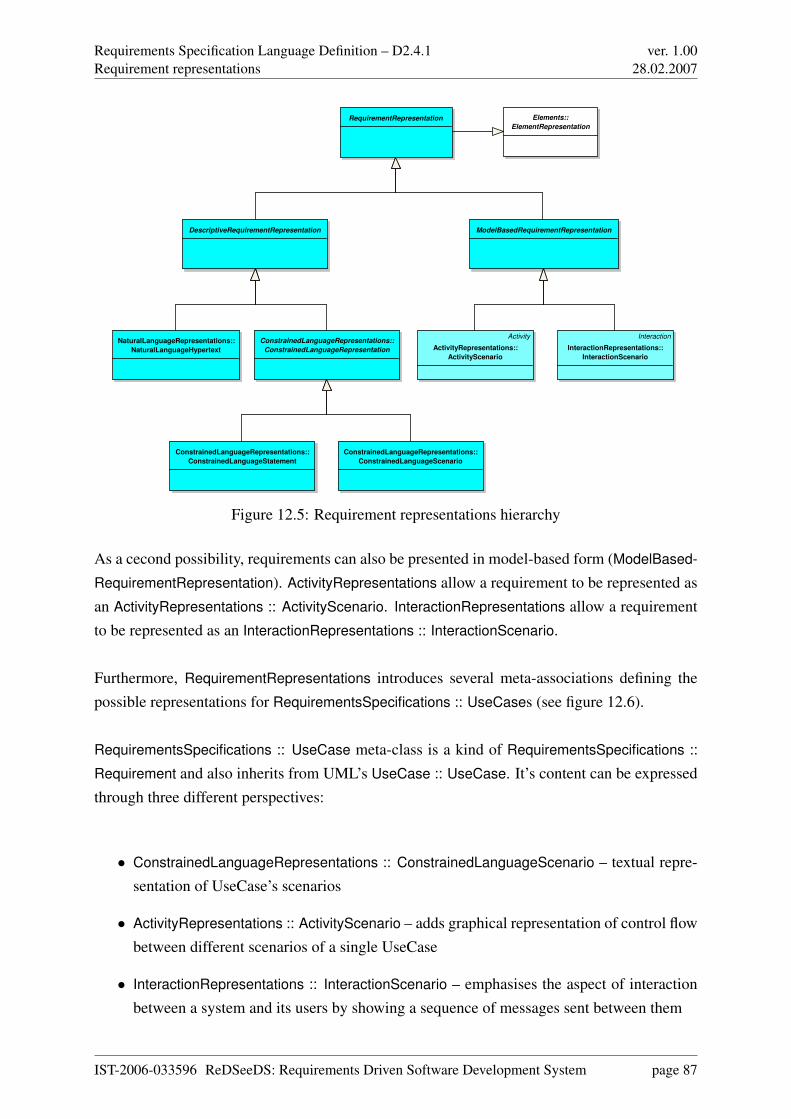
Requirements Specification Language Definition – D2.4.1Requirement representations
ver. 1.0028.02.2007
RequirementRepresentation
ConstrainedLanguageRepresentations::
ConstrainedLanguageRepresentation
ModelBasedRequirementRepresentation
Activity
ActivityRepresentations::
ActivityScenario
Interaction
InteractionRepresentations::
InteractionScenario
ConstrainedLanguageRepresentations::
ConstrainedLanguageScenario
NaturalLanguageRepresentations::
NaturalLanguageHypertext
ConstrainedLanguageRepresentations::
ConstrainedLanguageStatement
Elements::
ElementRepresentation
DescriptiveRequirementRepresentation
Figure 12.5: Requirement representations hierarchy
As a cecond possibility, requirements can also be presented in model-based form (ModelBased-
RequirementRepresentation). ActivityRepresentations allow a requirement to be represented asan ActivityRepresentations :: ActivityScenario. InteractionRepresentations allow a requirementto be represented as an InteractionRepresentations :: InteractionScenario.
Furthermore, RequirementRepresentations introduces several meta-associations defining thepossible representations for RequirementsSpecifications :: UseCases (see figure 12.6).
RequirementsSpecifications :: UseCase meta-class is a kind of RequirementsSpecifications ::
Requirement and also inherits from UML’s UseCase :: UseCase. It’s content can be expressedthrough three different perspectives:
• ConstrainedLanguageRepresentations :: ConstrainedLanguageScenario – textual repre-sentation of UseCase’s scenarios
• ActivityRepresentations :: ActivityScenario – adds graphical representation of control flowbetween different scenarios of a single UseCase
• InteractionRepresentations :: InteractionScenario – emphasises the aspect of interactionbetween a system and its users by showing a sequence of messages sent between them
IST-2006-033596 ReDSeeDS: Requirements Driven Software Development System page 87
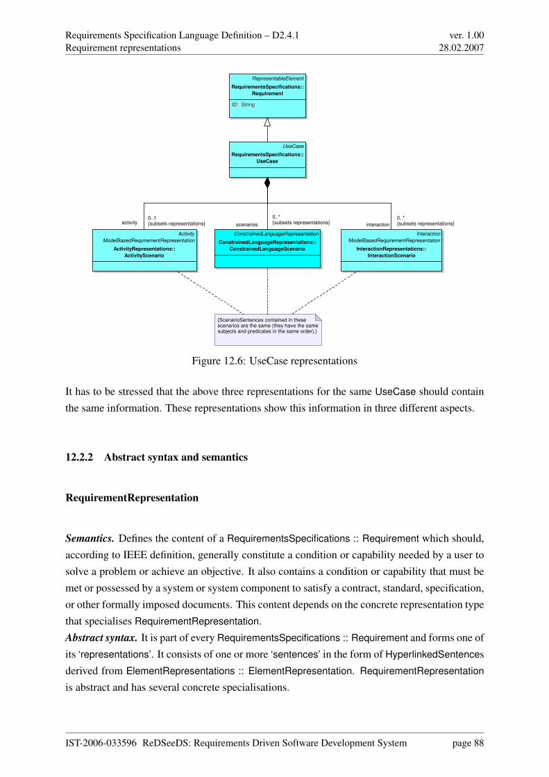
Requirements Specification Language Definition – D2.4.1Requirement representations
ver. 1.0028.02.2007
UseCase
RequirementsSpecifications::
UseCase
Activity
ModelBasedRequirementRepresentation
ActivityRepresentations::
ActivityScenario
ConstrainedLanguageRepresentation
ConstrainedLanguageRepresentations::
ConstrainedLanguageScenario
RepresentableElement
RequirementsSpecifications::
Requirement
ID: String
Interaction
ModelBasedRequirementRepresentation
InteractionRepresentations::
InteractionScenario
{ScenarioSentences contained in these scenarios are the same (they have the same subjects and predicates in the same order).}
activity0..1{subsets representations} scenarios
0..*{subsets representations} interaction
0..*{subsets representations}
Figure 12.6: UseCase representations
It has to be stressed that the above three representations for the same UseCase should containthe same information. These representations show this information in three different aspects.
12.2.2 Abstract syntax and semantics
RequirementRepresentation
Semantics. Defines the content of a RequirementsSpecifications :: Requirement which should,according to IEEE definition, generally constitute a condition or capability needed by a user tosolve a problem or achieve an objective. It also contains a condition or capability that must bemet or possessed by a system or system component to satisfy a contract, standard, specification,or other formally imposed documents. This content depends on the concrete representation typethat specialises RequirementRepresentation.Abstract syntax. It is part of every RequirementsSpecifications :: Requirement and forms one ofits ‘representations’. It consists of one or more ‘sentences’ in the form of HyperlinkedSentencesderived from ElementRepresentations :: ElementRepresentation. RequirementRepresentation
is abstract and has several concrete specialisations.
IST-2006-033596 ReDSeeDS: Requirements Driven Software Development System page 88
Requirements Specification Language Definition – D2.4.1Requirement representations
ver. 1.0028.02.2007
DescriptiveRequirementRepresentation
Semantics. This meta-class allows for textual representation of requirements in the form of freeor constrained text.Abstract syntax. It is a kind of RequirementRepresentations :: RequirementRepresentation.DescriptiveRequirementRepresentation is an abstract class.
ModelBasedRequirementRepresentation
Semantics. This meta-class allows for representing requirements in schematic form.Abstract syntax. It is a kind of RequirementRepresentations :: RequirementRepresentation.ModelBasedRequirementRepresentation is an abstract class.
Meta-associations between UseCase and its representations
Apart from the above meta-classes, this package defines several meta-associations that definerelationship between UseCases and their representations.
Appropriate abstract syntax is presented in Figure 12.6. UseCase is a special kind of Re-
quirement that can have its content represented by three RequirementRepresentations. Two ofthem are ModelBasedRequirementRepresentations and one of them is a DescriptiveRequire-
mentRepresentation. All the three representations of the UseCase content (ConstrainedLan-
guageRepresentations :: ConstrainedLanguageScenario, ActivityRepresentations :: ActivitySce-
nario and InteractionRepresentations :: InteractionScenario) are described in detail in sections12.4, 12.5 and 12.6, respectively.
12.2.3 Concrete syntax and examples
RequirementRepresentation. As an abstract meta-class, this meta-model element has no con-crete syntax. It can be formulated in any of representations of meta-classes that derive fromit.
IST-2006-033596 ReDSeeDS: Requirements Driven Software Development System page 89
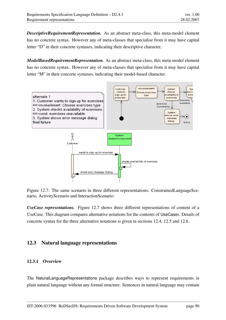
Requirements Specification Language Definition – D2.4.1Requirement representations
ver. 1.0028.02.2007
DescriptiveRequirementRepresentation. As an abstract meta-class, this meta-model elementhas no concrete syntax. However any of meta-classes that specialise from it may have capitalletter “D” in their concrete syntaxes, indicating their descriptive character.
ModelBasedRequirementRepresentation. As an abstract meta-class, this meta-model elementhas no concrete syntax. However any of meta-classes that specialise from it may have capitalletter “M” in their concrete syntaxes, indicating their model-based character.
Figure 12.7: The same scenario in three different representations: ConstrainedLanguageSce-nario, ActivityScenario and InteractionScenario
UseCase representations. Figure 12.7 shows three different representations of content of aUseCase. This diagram compares alternative notations for the contents of UseCases. Details ofconcrete syntax for the three alternative notations is given in sections 12.4, 12.5 and 12.6.
12.3 Natural language representations
12.3.1 Overview
The NaturalLanguageRepresentations package describes ways to represent requirements inplain natural language without any formal structure. Sentences in natural language may contain
IST-2006-033596 ReDSeeDS: Requirements Driven Software Development System page 90
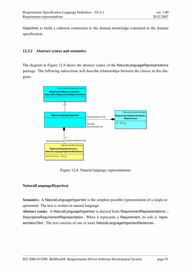
Requirements Specification Language Definition – D2.4.1Requirement representations
ver. 1.0028.02.2007
Hyperlinks to build a coherent connection to the domain knowledge contained in the domainspecification.
12.3.2 Abstract syntax and semantics
The diagram in Figure 12.8 shows the abstract syntax of the NaturalLanguageRepresentations
package. The following subsections will describe relationships between the classes in this dia-gram.
RepresentableElementRequirementsSpecifications::
Requirement
ID: String
NaturalLanguageHypertext
Hyperl inkedSentenceRepresentationSentences::
NaturalLanguageHypertextSentence
sentenceT ext: String
RequirementRepresentationRequirementRepresentations::
DescriptiveRequirementRepresentation
representationT ext
1{subsetsrepresentations}
textualSentences1..*{redefines sentences}
Figure 12.8: Natural language representations
NaturalLanguageHypertext
Semantics. A NaturalLanguageHypertext is the simplest possible representation of a single re-quirement. The text is written in natural language.Abstract syntax. A NaturalLanguageHypertext is derived from RequirementRepresentations ::
DescriptiveRequirementRepresentation. When it represents a Requirement, its role is ‘repre-
sentationText’. The text consists of one or more NaturalLanguageHypertextSentences.
IST-2006-033596 ReDSeeDS: Requirements Driven Software Development System page 91
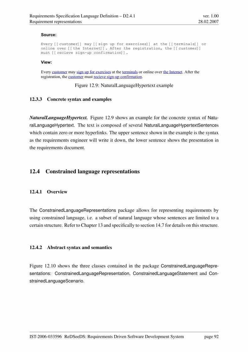
Requirements Specification Language Definition – D2.4.1Requirement representations
ver. 1.0028.02.2007
Source:
Every [[customer]] may [[sign up for exercises]] at the [[terminals]] or online over [[the Internet]]. After the registration, the [[customer]] must [[recieve sign-up confirmation]].
View:
Every customer may sign up for exercises at the terminals or online over the Internet. After the registration, the customer must recieve sign-up confirmation.
Figure 12.9: NaturalLanguageHypertext example
12.3.3 Concrete syntax and examples
NaturalLanguageHypertext. Figure 12.9 shows an example for the concrete syntax of Natu-
ralLanguageHypertext. The text is composed of several NaturalLanguageHypertextSentenceswhich contain zero or more hyperlinks. The upper sentence shown in the example is the syntaxas the requirements engineer will write it down, the lower sentence shows the presentation inthe requirements document.
12.4 Constrained language representations
12.4.1 Overview
The ConstrainedLanguageRepresentations package allows for representing requirements byusing constrained language, i.e. a subset of natural language whose sentences are limited to acertain structure. Refer to Chapter 13 and specifically to section 14.7 for details on this structure.
12.4.2 Abstract syntax and semantics
Figure 12.10 shows the three classes contained in the package ConstrainedLanguageRepre-
sentations: ConstrainedLanguageRepresentation, ConstrainedLanguageStatement and Con-
strainedLanguageScenario.
IST-2006-033596 ReDSeeDS: Requirements Driven Software Development System page 92
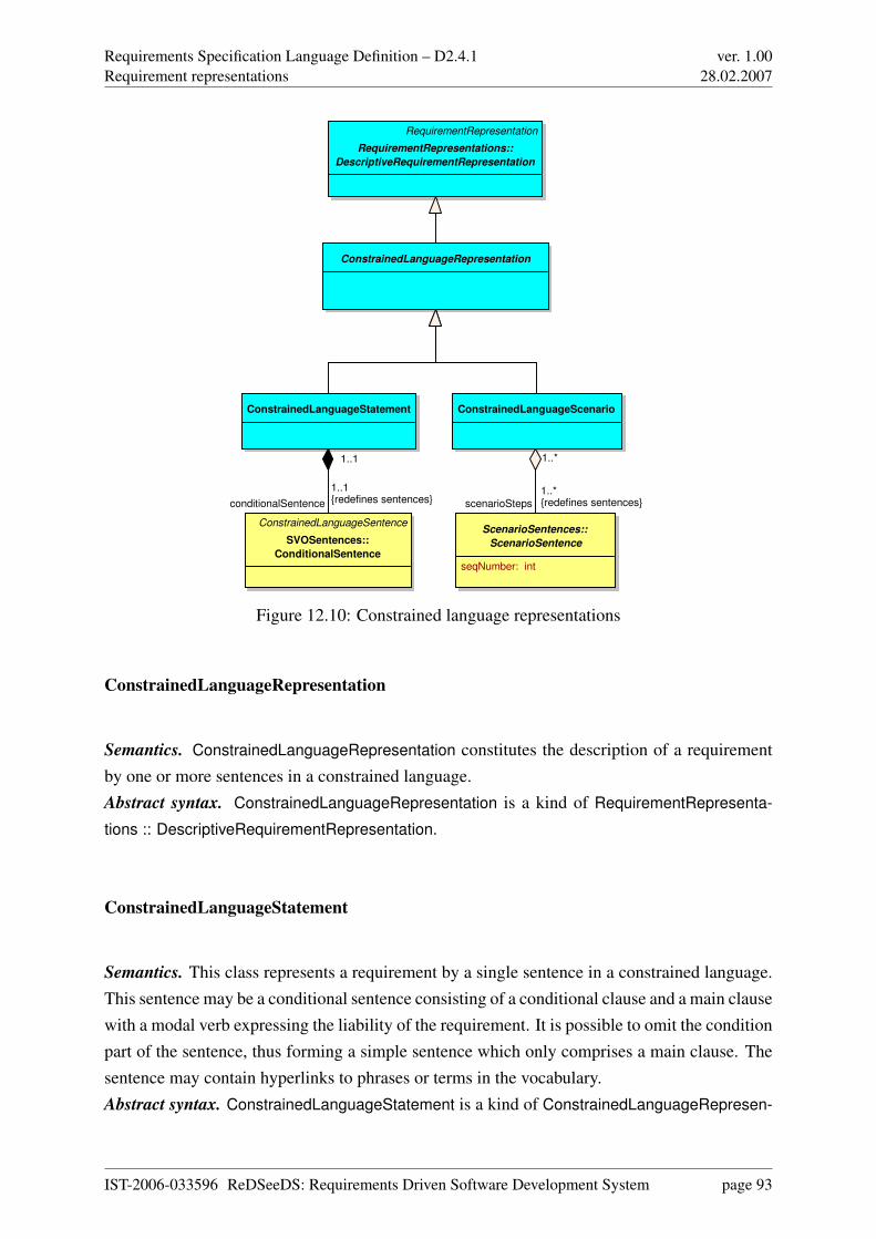
Requirements Specification Language Definition – D2.4.1Requirement representations
ver. 1.0028.02.2007
ConstrainedLanguageScenario
ScenarioSentences::
ScenarioSentence
seqNumber: int
ConstrainedLanguageRepresentation
ConstrainedLanguageStatement
RequirementRepresentation
RequirementRepresentations::
DescriptiveRequirementRepresentation
ConstrainedLanguageSentence
SVOSentences::
ConditionalSentence
scenarioSteps
1..*{redefines sentences}
1..*
conditionalSentence
1..1{redefines sentences}
1..1
Figure 12.10: Constrained language representations
ConstrainedLanguageRepresentation
Semantics. ConstrainedLanguageRepresentation constitutes the description of a requirementby one or more sentences in a constrained language.Abstract syntax. ConstrainedLanguageRepresentation is a kind of RequirementRepresenta-
tions :: DescriptiveRequirementRepresentation.
ConstrainedLanguageStatement
Semantics. This class represents a requirement by a single sentence in a constrained language.This sentence may be a conditional sentence consisting of a conditional clause and a main clausewith a modal verb expressing the liability of the requirement. It is possible to omit the conditionpart of the sentence, thus forming a simple sentence which only comprises a main clause. Thesentence may contain hyperlinks to phrases or terms in the vocabulary.Abstract syntax. ConstrainedLanguageStatement is a kind of ConstrainedLanguageRepresen-
IST-2006-033596 ReDSeeDS: Requirements Driven Software Development System page 93
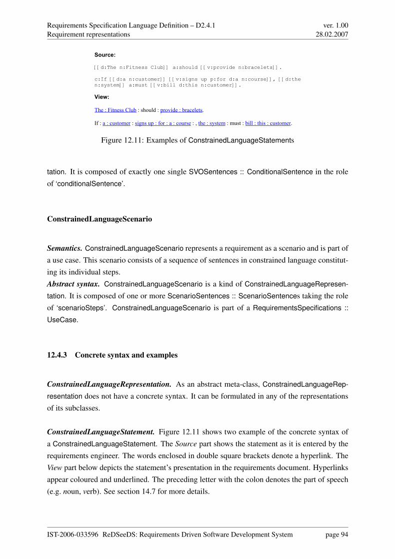
Requirements Specification Language Definition – D2.4.1Requirement representations
ver. 1.0028.02.2007
Source:
[[d:The n:Fitness Club]] a:should [[v:provide n:bracelets]].
c:If [[d:a n:customer]] [[v:signs up p:for d:a n:course]], [[d:the n:system]] a:must [[v:bill d:this n:customer]].
View:
The : Fitness Club : should : provide : bracelets.
If : a : customer : signs up : for : a : course : , the : system : must : bill : this : customer.
Figure 12.11: Examples of ConstrainedLanguageStatements
tation. It is composed of exactly one single SVOSentences :: ConditionalSentence in the roleof ‘conditionalSentence’.
ConstrainedLanguageScenario
Semantics. ConstrainedLanguageScenario represents a requirement as a scenario and is part ofa use case. This scenario consists of a sequence of sentences in constrained language constitut-ing its individual steps.Abstract syntax. ConstrainedLanguageScenario is a kind of ConstrainedLanguageRepresen-
tation. It is composed of one or more ScenarioSentences :: ScenarioSentences taking the roleof ‘scenarioSteps’. ConstrainedLanguageScenario is part of a RequirementsSpecifications ::
UseCase.
12.4.3 Concrete syntax and examples
ConstrainedLanguageRepresentation. As an abstract meta-class, ConstrainedLanguageRep-
resentation does not have a concrete syntax. It can be formulated in any of the representationsof its subclasses.
ConstrainedLanguageStatement. Figure 12.11 shows two example of the concrete syntax ofa ConstrainedLanguageStatement. The Source part shows the statement as it is entered by therequirements engineer. The words enclosed in double square brackets denote a hyperlink. TheView part below depicts the statement’s presentation in the requirements document. Hyperlinksappear coloured and underlined. The preceding letter with the colon denotes the part of speech(e.g. noun, verb). See section 14.7 for more details.
IST-2006-033596 ReDSeeDS: Requirements Driven Software Development System page 94
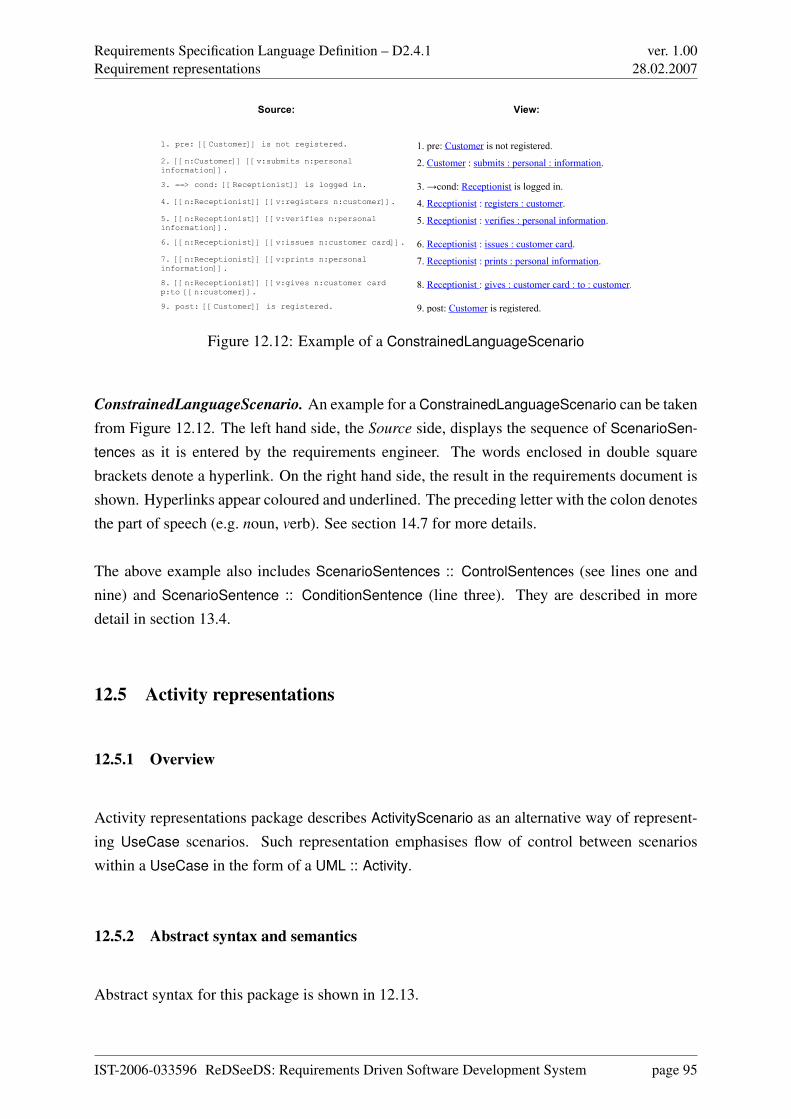
Requirements Specification Language Definition – D2.4.1Requirement representations
ver. 1.0028.02.2007
Source: View:
1. pre: [[Customer]] is not registered. 1. pre: Customer is not registered.2. [[n:Customer]] [[v:submits n:personalinformation]]. 2. Customer : submits : personal : information.
3. ==> cond: [[Receptionist]] is logged in. 3. →cond: Receptionist is logged in.4. [[n:Receptionist]] [[v:registers n:customer]]. 4. Receptionist : registers : customer.5. [[n:Receptionist]] [[v:verifies n:personalinformation]]. 5. Receptionist : verifies : personal information.
6. [[n:Receptionist]] [[v:issues n:customer card]]. 6. Receptionist : issues : customer card.7. [[n:Receptionist]] [[v:prints n:personalinformation]]. 7. Receptionist : prints : personal information.
8. [[n:Receptionist]] [[v:gives n:customer cardp:to [[n:customer]]. 8. Receptionist : gives : customer card : to : customer.
9. post: [[Customer]] is registered. 9. post: Customer is registered.
Figure 12.12: Example of a ConstrainedLanguageScenario
ConstrainedLanguageScenario. An example for a ConstrainedLanguageScenario can be takenfrom Figure 12.12. The left hand side, the Source side, displays the sequence of ScenarioSen-
tences as it is entered by the requirements engineer. The words enclosed in double squarebrackets denote a hyperlink. On the right hand side, the result in the requirements document isshown. Hyperlinks appear coloured and underlined. The preceding letter with the colon denotesthe part of speech (e.g. noun, verb). See section 14.7 for more details.
The above example also includes ScenarioSentences :: ControlSentences (see lines one andnine) and ScenarioSentence :: ConditionSentence (line three). They are described in moredetail in section 13.4.
12.5 Activity representations
12.5.1 Overview
Activity representations package describes ActivityScenario as an alternative way of represent-ing UseCase scenarios. Such representation emphasises flow of control between scenarioswithin a UseCase in the form of a UML :: Activity.
12.5.2 Abstract syntax and semantics
Abstract syntax for this package is shown in 12.13.
IST-2006-033596 ReDSeeDS: Requirements Driven Software Development System page 95
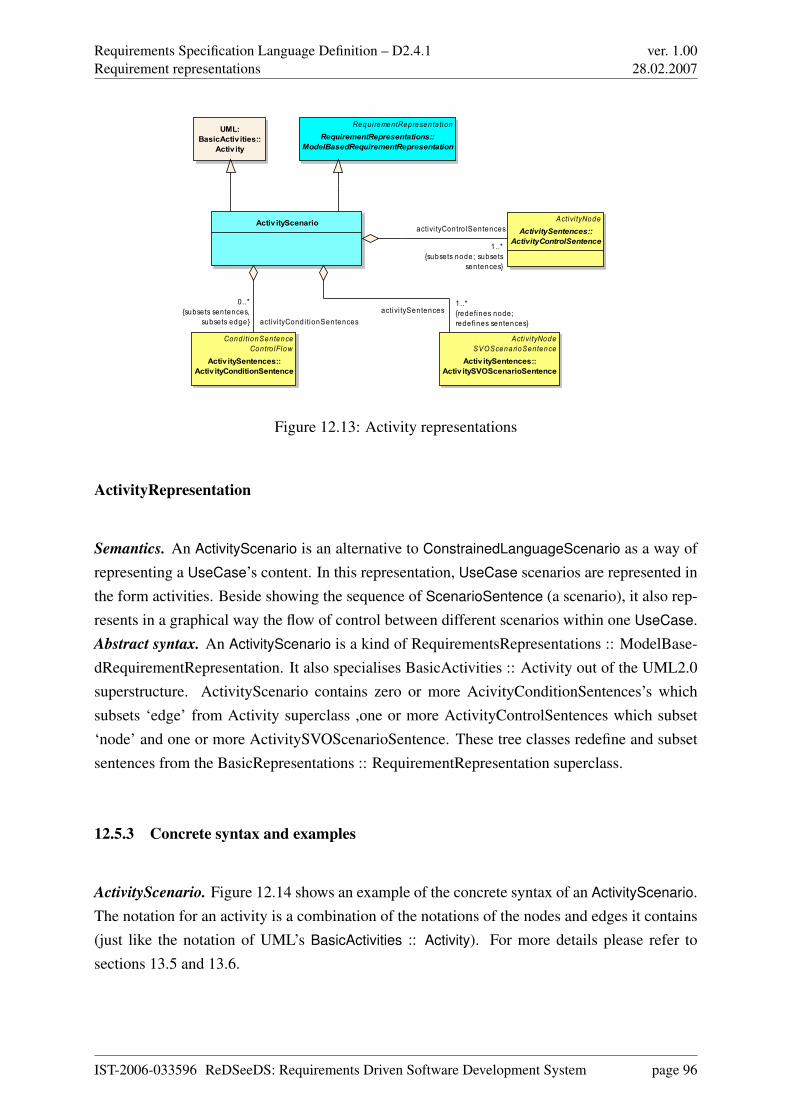
Requirements Specification Language Definition – D2.4.1Requirement representations
ver. 1.0028.02.2007
Activ ityScenario
UML:BasicActiv ities::
Activ ity
RequirementRepresentationRequirementRepresentations::
ModelBasedRequirementRepresentation
Condi tionSentenceContro lFlow
Activ itySentences::Activ ityConditionSentence
Activi tyNodeActivitySentences::
ActivityControlSentence
Activi tyNodeSVOScenarioSentence
Activ itySentences::Activ itySVOScenarioSentence
activi tySentences1..*{redefines node;redefines sentences}
activi tyContro lSentences
1..*{subsets node; subsets
sentences}
activi tyCondi tionSentences
0..*{subsets sentences,
subsets edge}
Figure 12.13: Activity representations
ActivityRepresentation
Semantics. An ActivityScenario is an alternative to ConstrainedLanguageScenario as a way ofrepresenting a UseCase’s content. In this representation, UseCase scenarios are represented inthe form activities. Beside showing the sequence of ScenarioSentence (a scenario), it also rep-resents in a graphical way the flow of control between different scenarios within one UseCase.Abstract syntax. An ActivityScenario is a kind of RequirementsRepresentations :: ModelBase-dRequirementRepresentation. It also specialises BasicActivities :: Activity out of the UML2.0superstructure. ActivityScenario contains zero or more AcivityConditionSentences’s whichsubsets ‘edge’ from Activity superclass ,one or more ActivityControlSentences which subset‘node’ and one or more ActivitySVOScenarioSentence. These tree classes redefine and subsetsentences from the BasicRepresentations :: RequirementRepresentation superclass.
12.5.3 Concrete syntax and examples
ActivityScenario. Figure 12.14 shows an example of the concrete syntax of an ActivityScenario.The notation for an activity is a combination of the notations of the nodes and edges it contains(just like the notation of UML’s BasicActivities :: Activity). For more details please refer tosections 13.5 and 13.6.
IST-2006-033596 ReDSeeDS: Requirements Driven Software Development System page 96
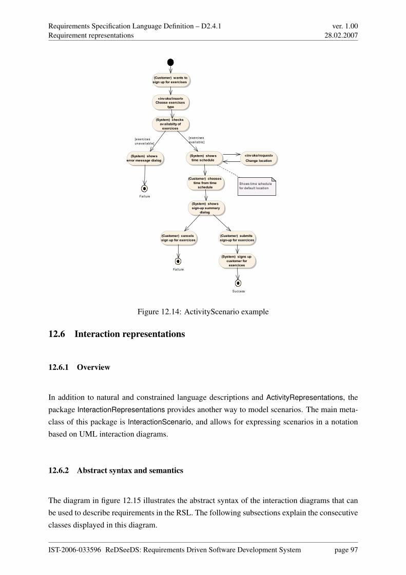
Requirements Specification Language Definition – D2.4.1Requirement representations
ver. 1.0028.02.2007
«...
(System) shows time schedule
(System) checks availabilty of
exercices
«invoke/insert»Choose exercises
type
(Customer) wants to sign up for exercises
«...Fai lure
(Customer) cancels sign up for exercices
«...Fai lure
(System) shows error message dialog
«...Success
(System) signs up customer for
exercices
(Customer) submits sign-up for exercices
(System) shows sign-up summary
dialog
«invoke/request»Change location
(Customer) chooses time from time
schedule Shows tim e schedule for defaul t location
[exercisesavai lable ]
[exercicesunavai lable]
Figure 12.14: ActivityScenario example
12.6 Interaction representations
12.6.1 Overview
In addition to natural and constrained language descriptions and ActivityRepresentations, thepackage InteractionRepresentations provides another way to model scenarios. The main meta-class of this package is InteractionScenario, and allows for expressing scenarios in a notationbased on UML interaction diagrams.
12.6.2 Abstract syntax and semantics
The diagram in figure 12.15 illustrates the abstract syntax of the interaction diagrams that canbe used to describe requirements in the RSL. The following subsections explain the consecutiveclasses displayed in this diagram.
IST-2006-033596 ReDSeeDS: Requirements Driven Software Development System page 97
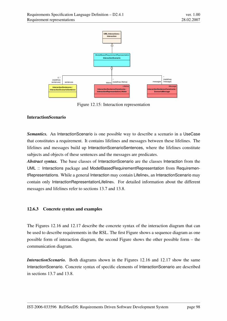
Requirements Specification Language Definition – D2.4.1Requirement representations
ver. 1.0028.02.2007
ModelBasedRequirementRepresentation
InteractionScenario
UML:Interactions::
Interaction
InteractionSentences::
InteractionScenarioSentence
Message
InteractionSentenceConstructs::
ScenarioMessage
Lifeline
InteractionSentenceConstructs::
InteractionRepresentationLifeline
sentences
0..*
{redefines
sentences} messages
*
{redefines
message}lifeline
*
{redefines lifeline}
Figure 12.15: Interaction representation
InteractionScenario
Semantics. An InteractionScenario is one possible way to describe a scenario in a UseCase
that constitutes a requirement. It contains lifelines and messages between these lifelines. Thelifelines and messages build up InteractionScenarioSentences, where the lifelines constitutesubjects and objects of these sentences and the messages are predicates.Abstract syntax. The base classes of InteractionScenario are the classes Interaction from theUML :: Interactions package and ModelBasedRequirementRepresentation from Requiremen-
tRepresentations. While a general Interaction may contain Lifelines, an InteractionScenario maycontain only InteractionRepresentationLifelines. For detailed information about the differentmessages and lifelines refer to sections 13.7 and 13.8.
12.6.3 Concrete syntax and examples
The Figures 12.16 and 12.17 describe the concrete syntax of the interaction diagram that canbe used to describe requirements in the RSL. The first Figure shows a sequence diagram as onepossible form of interaction diagram, the second Figure shows the other possible form – thecommunication diagram.
InteractionScenario. Both diagrams shown in the Figures 12.16 and 12.17 show the sameInteractionScenario. Concrete syntax of specific elements of InteractionScenario are describedin sections 13.7 and 13.8.
IST-2006-033596 ReDSeeDS: Requirements Driven Software Development System page 98
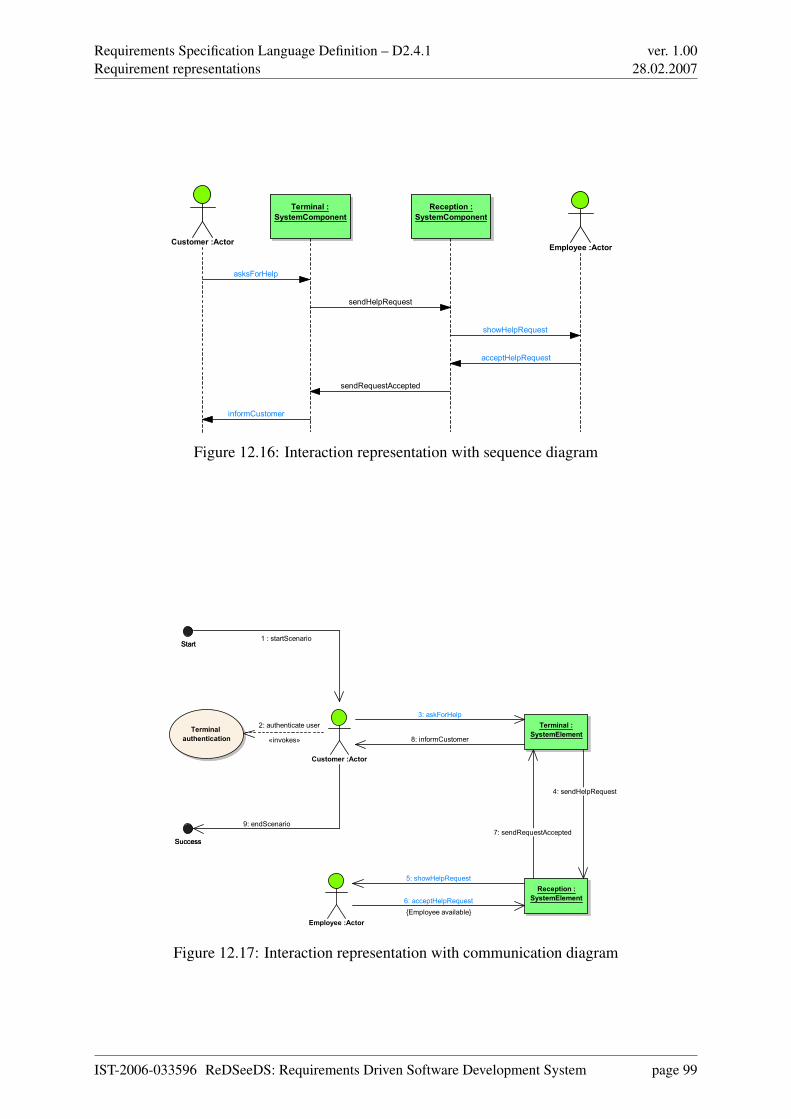
Requirements Specification Language Definition – D2.4.1Requirement representations
ver. 1.0028.02.2007
Terminal :
SystemComponent
Reception :
SystemComponent
Customer :ActorEmployee :Actor
asksForHelp
sendHelpRequest
showHelpRequest
acceptHelpRequest
sendRequestAccepted
informCustomer
Figure 12.16: Interaction representation with sequence diagram
Customer :Actor
Reception :
SystemElement
Terminal :
SystemElement
Employee :Actor
Terminal
authentication
StartStart
SuccessSuccess
1 : startScenario
6: acceptHelpRequest
{Employee available}
4: sendHelpRequest
8: informCustomer
5: showHelpRequest
7: sendRequestAccepted
9: endScenario
2: authenticate user
«invokes»
3: askForHelp
Figure 12.17: Interaction representation with communication diagram
IST-2006-033596 ReDSeeDS: Requirements Driven Software Development System page 99
Requirements Specification Language Definition – D2.4.1Requirement representation sentences
ver. 1.0028.02.2007
Chapter 13
Requirement representation sentences
13.1 Overview
This chapter covers the different types of sentences in constrained language which can beused to represent requirements. Figures 13.1 and 13.2 give an overview of the seven pack-ages (marked in yellow on colour print-outs) inside this part of the Requirements SpecificationLanguage.
• The RepresentationSentences package contains classes representing single sentences innatural and constrained language. The class representing a single sentence in constrainedlanguage is abstract and it has its concrete specialisations in the other two packages de-scribed below. RepresentationSentences packages «import»s from Kernel :: Elements inorder to reuse the syntax and semantics of more general elements.
• Inside the SVOSentences1 package, there exist constructs representing concrete types ofconstrained language sentences and their breakdown into more fine-granular elements,such as Subject or Predicate. Therefore SVOSentences package «import»s from Repre-
sentationSentences package, Phrases package and Terms package.
• The contents of the ScenarioSentences package which imports SVOSentences are usedfor describing sentences of scenarios. They differ from “ordinary” SVOSentences bycontaining a sequence number denoting their position inside the scenario. The subtypesof a ScenarioSentence allow for describing a single scenario step as well as for expressing
1SVO stands for subject – verb – object. The identifier refers to the SVO(O) (subject – verb – object – (object))grammar used for the constrained language.
IST-2006-033596 ReDSeeDS: Requirements Driven Software Development System page 100
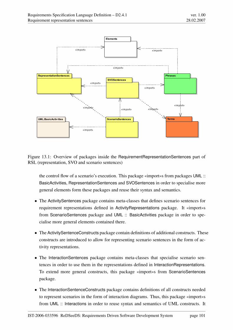
Requirements Specification Language Definition – D2.4.1Requirement representation sentences
ver. 1.0028.02.2007
RepresentationSentencesSVOSentences
ScenarioSentences
Phrases
Terms
Elements
UML:BasicActiv ities
«import»
«import»
«import»
«import»
«import»
«import»«import»
«import»«import»
«import»
Figure 13.1: Overview of packages inside the RequirementRepresentationSentences part ofRSL (representation, SVO and scenario sentences)
the control flow of a scenario’s execution. This package «import»s from packages UML ::
BasicActivities, RepresentationSentences and SVOSentences in order to specialise moregeneral elements form these packages and reuse their syntax and semantics.
• The ActivitySentences package contains meta-classes that defines scenario sentences forrequirement representations defined in ActivityRepresentations package. It «import»sfrom ScenarioSentences package and UML :: BasicActivities package in order to spe-cialise more general elements contained there.
• The ActivitySentenceConstructs package contain definitions of additional constructs. Theseconstructs are introduced to allow for representing scenario sentences in the form of ac-tivity representations.
• The InteractionSentences package contains meta-classes that specialise scenario sen-tences in order to use them in the representations defined in InteractionRepresentations.To extend more general constructs, this package «import»s from ScenarioSentences
package.
• The InteractionSentenceConstructs package contains definitions of all constructs neededto represent scenarios in the form of interaction diagrams. Thus, this package «import»sfrom UML :: Interactions in order to reuse syntax and semantics of UML constructs. It
IST-2006-033596 ReDSeeDS: Requirements Driven Software Development System page 101
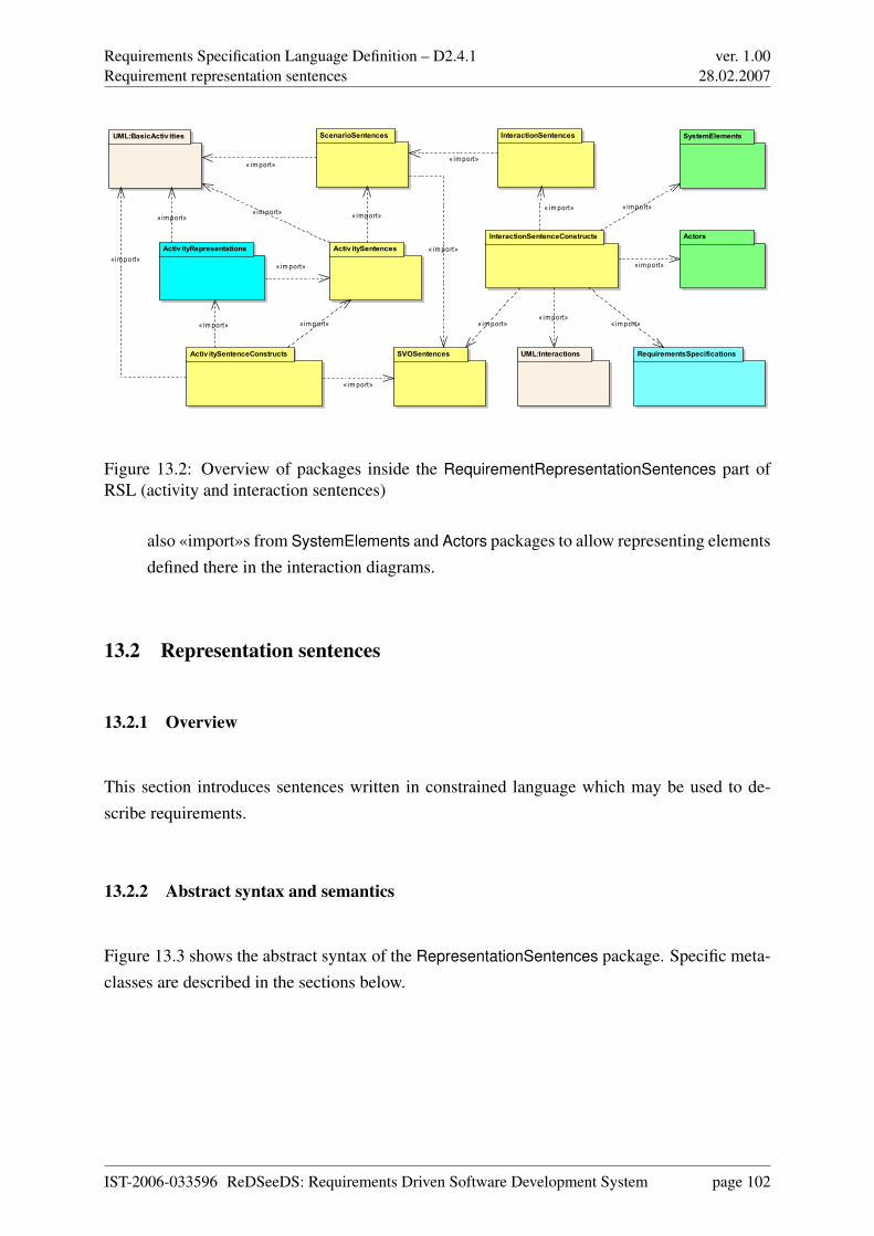
Requirements Specification Language Definition – D2.4.1Requirement representation sentences
ver. 1.0028.02.2007
SVOSentences
ScenarioSentences
Activ itySentences
Activ itySentenceConstructs
InteractionSentencesUML:BasicActiv ities
InteractionSentenceConstructsActiv ityRepresentations
UML:Interactions
Actors
SystemElements
RequirementsSpecifications
«im port» « im port»
« im port»
« im port»« im port»
« im port»
« im port»
« im port»
« im port»« im port»
« im port»
« im port»
« import»
« im port»
« im port»
« im port»
« im port»
Figure 13.2: Overview of packages inside the RequirementRepresentationSentences part ofRSL (activity and interaction sentences)
also «import»s from SystemElements and Actors packages to allow representing elementsdefined there in the interaction diagrams.
13.2 Representation sentences
13.2.1 Overview
This section introduces sentences written in constrained language which may be used to de-scribe requirements.
13.2.2 Abstract syntax and semantics
Figure 13.3 shows the abstract syntax of the RepresentationSentences package. Specific meta-classes are described in the sections below.
IST-2006-033596 ReDSeeDS: Requirements Driven Software Development System page 102
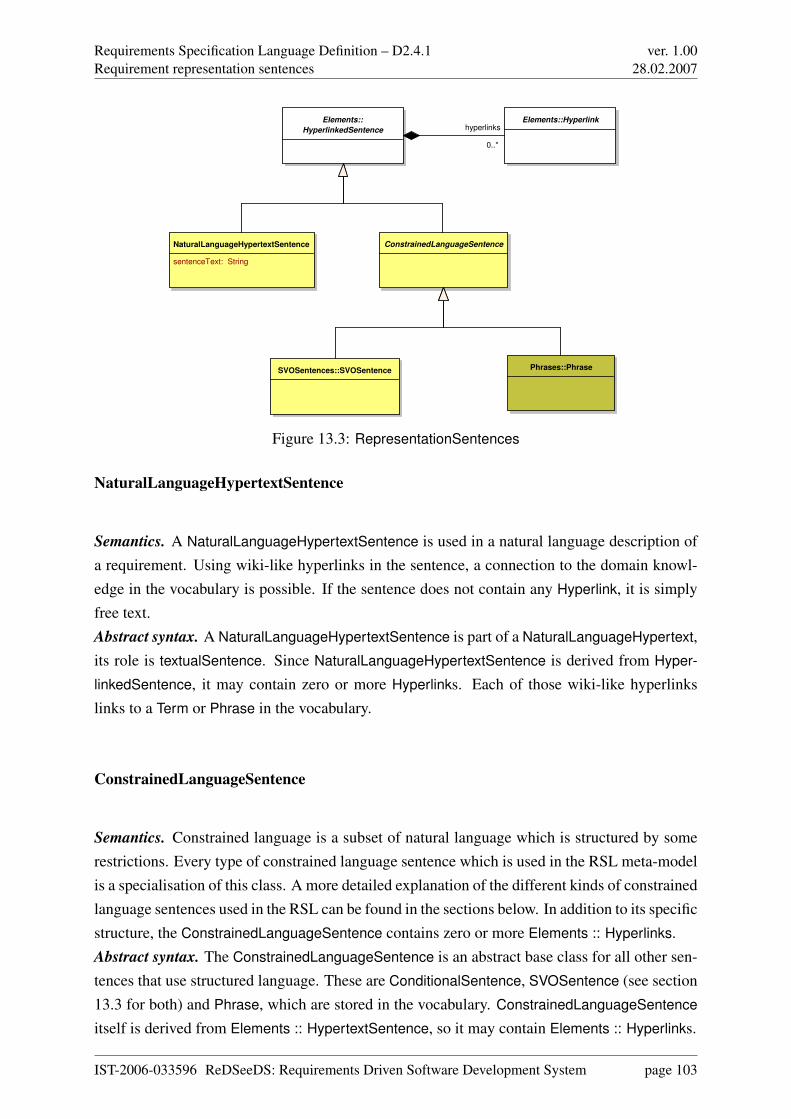
Requirements Specification Language Definition – D2.4.1Requirement representation sentences
ver. 1.0028.02.2007
Elements::
HyperlinkedSentence
NaturalLanguageHypertextSentence
sentenceText: String
ConstrainedLanguageSentence
Phrases::PhraseSVOSentences::SVOSentence
Elements::Hyperlinkhyperlinks
0..*
Figure 13.3: RepresentationSentences
NaturalLanguageHypertextSentence
Semantics. A NaturalLanguageHypertextSentence is used in a natural language description ofa requirement. Using wiki-like hyperlinks in the sentence, a connection to the domain knowl-edge in the vocabulary is possible. If the sentence does not contain any Hyperlink, it is simplyfree text.Abstract syntax. A NaturalLanguageHypertextSentence is part of a NaturalLanguageHypertext,its role is textualSentence. Since NaturalLanguageHypertextSentence is derived from Hyper-
linkedSentence, it may contain zero or more Hyperlinks. Each of those wiki-like hyperlinkslinks to a Term or Phrase in the vocabulary.
ConstrainedLanguageSentence
Semantics. Constrained language is a subset of natural language which is structured by somerestrictions. Every type of constrained language sentence which is used in the RSL meta-modelis a specialisation of this class. A more detailed explanation of the different kinds of constrainedlanguage sentences used in the RSL can be found in the sections below. In addition to its specificstructure, the ConstrainedLanguageSentence contains zero or more Elements :: Hyperlinks.Abstract syntax. The ConstrainedLanguageSentence is an abstract base class for all other sen-tences that use structured language. These are ConditionalSentence, SVOSentence (see section13.3 for both) and Phrase, which are stored in the vocabulary. ConstrainedLanguageSentence
itself is derived from Elements :: HypertextSentence, so it may contain Elements :: Hyperlinks.
IST-2006-033596 ReDSeeDS: Requirements Driven Software Development System page 103
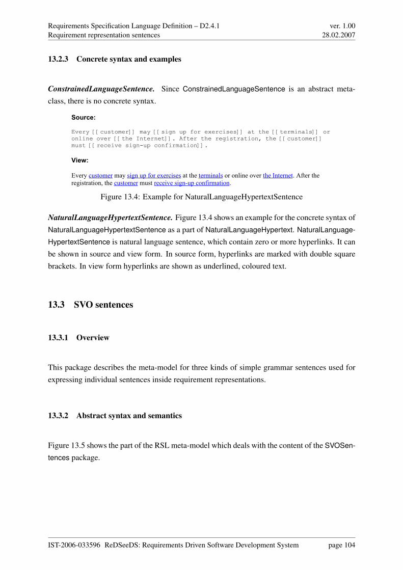
Requirements Specification Language Definition – D2.4.1Requirement representation sentences
ver. 1.0028.02.2007
13.2.3 Concrete syntax and examples
ConstrainedLanguageSentence. Since ConstrainedLanguageSentence is an abstract meta-class, there is no concrete syntax.
Source:
Every [[customer]] may [[sign up for exercises]] at the [[terminals]] or online over [[the Internet]]. After the registration, the [[customer]] must [[receive sign-up confirmation]].
View:
Every customer may sign up for exercises at the terminals or online over the Internet. After the registration, the customer must receive sign-up confirmation.
Figure 13.4: Example for NaturalLanguageHypertextSentence
NaturalLanguageHypertextSentence. Figure 13.4 shows an example for the concrete syntax ofNaturalLanguageHypertextSentence as a part of NaturalLanguageHypertext. NaturalLanguage-
HypertextSentence is natural language sentence, which contain zero or more hyperlinks. It canbe shown in source and view form. In source form, hyperlinks are marked with double squarebrackets. In view form hyperlinks are shown as underlined, coloured text.
13.3 SVO sentences
13.3.1 Overview
This package describes the meta-model for three kinds of simple grammar sentences used forexpressing individual sentences inside requirement representations.
13.3.2 Abstract syntax and semantics
Figure 13.5 shows the part of the RSL meta-model which deals with the content of the SVOSen-
tences package.
IST-2006-033596 ReDSeeDS: Requirements Driven Software Development System page 104
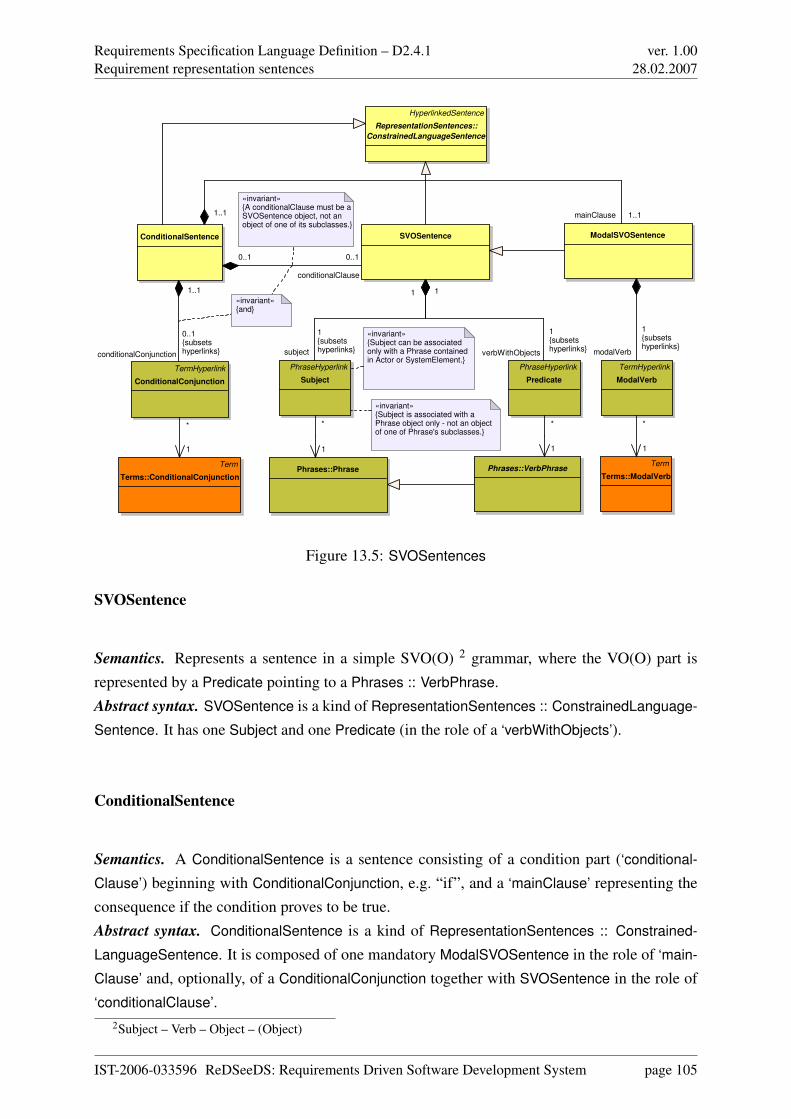
Requirements Specification Language Definition – D2.4.1Requirement representation sentences
ver. 1.0028.02.2007
ModalSVOSentence
Term
Terms::ModalVerbPhrases::Phrase Phrases::VerbPhrase
PhraseHyperlink
Subject
PhraseHyperlink
Predicate
TermHyperlink
ModalVerb
SVOSentence
«invariant»{Subject is associated with a Phrase object only - not an object of one of Phrase's subclasses.}
HyperlinkedSentence
RepresentationSentences::
ConstrainedLanguageSentence
«invariant»{Subject can be associated only with a Phrase contained in Actor or SystemElement.}
ConditionalSentence
TermHyperlink
ConditionalConjunction
Term
Terms::ConditionalConjunction
«invariant»{and}
«invariant»{A conditionalClause must be a SVOSentence object, not an object of one of its subclasses.}
conditionalConjunction
0..1{subsetshyperlinks}
1..1
verbWithObjects
1{subsetshyperlinks}
1
subject
1{subsetshyperlinks}
1
*
1
1..1 mainClause 1..1
*
1
*
1
*
1
modalVerb
1{subsetshyperlinks}
0..1
conditionalClause
0..1
Figure 13.5: SVOSentences
SVOSentence
Semantics. Represents a sentence in a simple SVO(O) 2 grammar, where the VO(O) part isrepresented by a Predicate pointing to a Phrases :: VerbPhrase.Abstract syntax. SVOSentence is a kind of RepresentationSentences :: ConstrainedLanguage-
Sentence. It has one Subject and one Predicate (in the role of a ‘verbWithObjects’).
ConditionalSentence
Semantics. A ConditionalSentence is a sentence consisting of a condition part (‘conditional-
Clause’) beginning with ConditionalConjunction, e.g. “if”, and a ‘mainClause’ representing theconsequence if the condition proves to be true.Abstract syntax. ConditionalSentence is a kind of RepresentationSentences :: Constrained-
LanguageSentence. It is composed of one mandatory ModalSVOSentence in the role of ‘main-
Clause’ and, optionally, of a ConditionalConjunction together with SVOSentence in the role of‘conditionalClause’.
2Subject – Verb – Object – (Object)
IST-2006-033596 ReDSeeDS: Requirements Driven Software Development System page 105
Requirements Specification Language Definition – D2.4.1Requirement representation sentences
ver. 1.0028.02.2007
ModalSVOSentence
Semantics. ModalSVOSentence is a SVOSentence extended by a ModalVerb allowing to ex-press: 1) the priority of the described activity, 2) the modality of the described activity, 3) theobligation or possibility of the subject to perform an action (described by a Predicate)Abstract syntax. ModalSVOSentence is a kind of SVOSentence with an additional ModalVerb
(kind of Terms :: TermHyperlink) pointing to a Terms :: ModalVerb. It constitutes the ‘main-
Clause’ of a ConditionalSentence.
ConditionalConjunction
Semantics. ConditionalConjunction is part of a ConditionalSentence and commences the ‘con-
ditionalClause’.Abstract syntax. ConditionalConjunction is a kind of Terms :: TermHyperlink that, as part ofConditionalSentence, subsets ‘hyperlink’, being part of Elements :: HyperlinkedSentence. Itpoints to a Terms :: ConditionalConjunction (see section 14.8).
Subject
Semantics. Subject denotes the part of an SVOSentence being its subject from the point of viewof natural language grammar. Subject points to a Phrases :: Phrase that is associated with anActors :: Actor or SystemRepresentations :: SystemUnderDevelopment (see sections 14.4 and14.5). This element can perform an action described by the predicate of the SVOSentence.Abstract syntax. Subject is a kind of Phrases :: PhraseHyperlink that in a context of an SVOSen-
tence subsets the ‘hyperlink’ being part of a Elements :: HyperlinkedSentence. It is thus part ofan SVOSentence and points to a Phrases :: Phrase. The Phrase that is associated with theSubject cannot be one of Phrase’s subclasses. The Phrases :: Phrase has to belong to an Actors
:: Actor or a SystemElements :: SystemElement.
Predicate
Semantics. Predicate hyperlinks an action performed by a Subject and all the words governedby this action’s Phrases :: VerbPhrase or modifying it in a given SVOSentence.Abstract syntax. Predicate is kind of Phrases :: PhraseHyperlink that in a context of SVOSen-
IST-2006-033596 ReDSeeDS: Requirements Driven Software Development System page 106
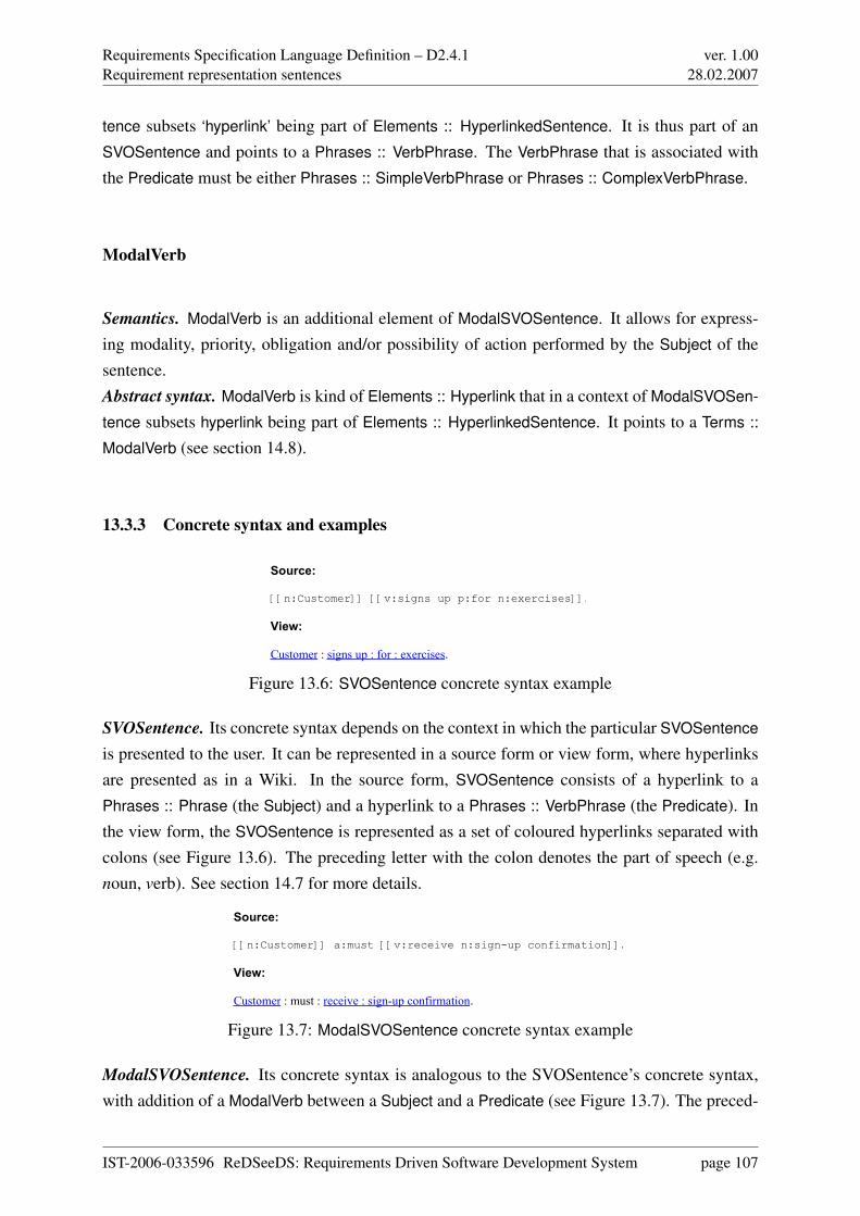
Requirements Specification Language Definition – D2.4.1Requirement representation sentences
ver. 1.0028.02.2007
tence subsets ‘hyperlink’ being part of Elements :: HyperlinkedSentence. It is thus part of anSVOSentence and points to a Phrases :: VerbPhrase. The VerbPhrase that is associated withthe Predicate must be either Phrases :: SimpleVerbPhrase or Phrases :: ComplexVerbPhrase.
ModalVerb
Semantics. ModalVerb is an additional element of ModalSVOSentence. It allows for express-ing modality, priority, obligation and/or possibility of action performed by the Subject of thesentence.Abstract syntax. ModalVerb is kind of Elements :: Hyperlink that in a context of ModalSVOSen-
tence subsets hyperlink being part of Elements :: HyperlinkedSentence. It points to a Terms ::
ModalVerb (see section 14.8).
13.3.3 Concrete syntax and examples
Source:
[[n:Customer]] [[v:signs up p:for n:exercises]].
View:
Customer : signs up : for : exercises.
Figure 13.6: SVOSentence concrete syntax example
SVOSentence. Its concrete syntax depends on the context in which the particular SVOSentence
is presented to the user. It can be represented in a source form or view form, where hyperlinksare presented as in a Wiki. In the source form, SVOSentence consists of a hyperlink to aPhrases :: Phrase (the Subject) and a hyperlink to a Phrases :: VerbPhrase (the Predicate). Inthe view form, the SVOSentence is represented as a set of coloured hyperlinks separated withcolons (see Figure 13.6). The preceding letter with the colon denotes the part of speech (e.g.noun, verb). See section 14.7 for more details.
Source:
[[n:Customer]] a:must [[v:receive n:sign-up confirmation]].
View:
Customer : must : receive : sign-up confirmation.
Figure 13.7: ModalSVOSentence concrete syntax example
ModalSVOSentence. Its concrete syntax is analogous to the SVOSentence’s concrete syntax,with addition of a ModalVerb between a Subject and a Predicate (see Figure 13.7). The preced-
IST-2006-033596 ReDSeeDS: Requirements Driven Software Development System page 107
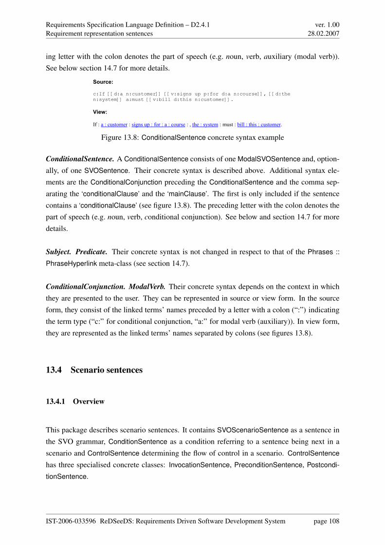
Requirements Specification Language Definition – D2.4.1Requirement representation sentences
ver. 1.0028.02.2007
ing letter with the colon denotes the part of speech (e.g. noun, verb, auxiliary (modal verb)).See below section 14.7 for more details.
Source:
c:If [[d:a n:customer]] [[v:signs up p:for d:a n:course]], [[d:the n:system]] a:must [[v:bill d:this n:customer]].
View:
If : a : customer : signs up : for : a : course : , the : system : must : bill : this : customer.
Figure 13.8: ConditionalSentence concrete syntax example
ConditionalSentence. A ConditionalSentence consists of one ModalSVOSentence and, option-ally, of one SVOSentence. Their concrete syntax is described above. Additional syntax ele-ments are the ConditionalConjunction preceding the ConditionalSentence and the comma sep-arating the ‘conditionalClause’ and the ‘mainClause’. The first is only included if the sentencecontains a ‘conditionalClause’ (see figure 13.8). The preceding letter with the colon denotes thepart of speech (e.g. noun, verb, conditional conjunction). See below and section 14.7 for moredetails.
Subject. Predicate. Their concrete syntax is not changed in respect to that of the Phrases ::
PhraseHyperlink meta-class (see section 14.7).
ConditionalConjunction. ModalVerb. Their concrete syntax depends on the context in whichthey are presented to the user. They can be represented in source or view form. In the sourceform, they consist of the linked terms’ names preceded by a letter with a colon (“:”) indicatingthe term type (“c:” for conditional conjunction, “a:” for modal verb (auxiliary)). In view form,they are represented as the linked terms’ names separated by colons (see figures 13.8).
13.4 Scenario sentences
13.4.1 Overview
This package describes scenario sentences. It contains SVOScenarioSentence as a sentence inthe SVO grammar, ConditionSentence as a condition referring to a sentence being next in ascenario and ControlSentence determining the flow of control in a scenario. ControlSentence
has three specialised concrete classes: InvocationSentence, PreconditionSentence, Postcondi-
tionSentence.
IST-2006-033596 ReDSeeDS: Requirements Driven Software Development System page 108
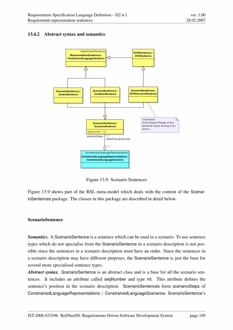
Requirements Specification Language Definition – D2.4.1Requirement representation sentences
ver. 1.0028.02.2007
13.4.2 Abstract syntax and semantics
ScenarioSentences::ScenarioSentence
seqNum ber: in t
ScenarioSentences::ControlSentence
Hyperl inkedSentenceRepresentationSentences::
ConstrainedLanguageSentence
ScenarioSentences::SVOScenarioSentence
«invariant»{T he Subject Phrase of th is sentence has to belong to an Actor.}
ScenarioSentences::ConditionSentence
SVOSentences::SVOSentence
Constra inedLanguageRepresentationConstrainedLanguageRepresentations::
ConstrainedLanguageScenario
scenarioSteps 1..*{redefines sentences}
1..*
Figure 13.9: Scenario Sentences
Figure 13.9 shows part of the RSL meta-model which deals with the content of the Scenar-
ioSentences package. The classes in this package are described in detail below.
ScenarioSentence
Semantics. A ScenarioSentence is a sentence which can be used in a scenario. To use sentencetypes which do not specialise from the ScenarioSentence in a scenario description is not pos-sible since the sentences in a scenario description must have an order. Since the sentences ina scenario description may have different purposes, the ScenarioSentence is just the base forseveral more specialised sentence types.Abstract syntax. ScenarioSentence is an abstract class and is a base for all the scenario sen-tences. It includes an attribute called seqNumber and type int. This attribute defines thesentence’s position in the scenario description. ScenarioSentences form scenarioSteps ofConstrainedLanguageRepresentations :: ConstrainedLanguageScenarios. ScenarioSentence’s
IST-2006-033596 ReDSeeDS: Requirements Driven Software Development System page 109
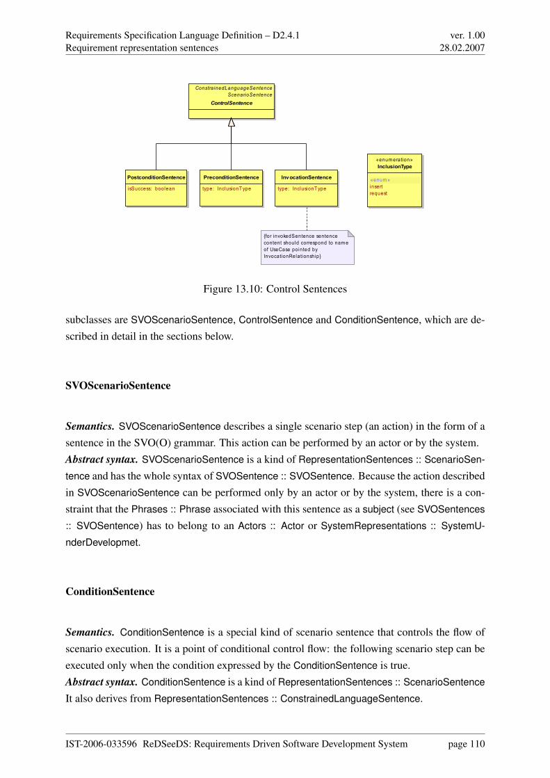
Requirements Specification Language Definition – D2.4.1Requirement representation sentences
ver. 1.0028.02.2007
InvocationSentence
type: InclusionT ype
PostconditionSentence
isSuccess: boolean
PreconditionSentence
type: InclusionT ype
«enum eration»InclusionType
«enum »insertrequest
ConstrainedLanguageSentenceScenarioSentence
ControlSentence
{for invokedSentence sentence content should correspond to nam e of UseCase pointed by InvocationRelationship}
Figure 13.10: Control Sentences
subclasses are SVOScenarioSentence, ControlSentence and ConditionSentence, which are de-scribed in detail in the sections below.
SVOScenarioSentence
Semantics. SVOScenarioSentence describes a single scenario step (an action) in the form of asentence in the SVO(O) grammar. This action can be performed by an actor or by the system.Abstract syntax. SVOScenarioSentence is a kind of RepresentationSentences :: ScenarioSen-
tence and has the whole syntax of SVOSentence :: SVOSentence. Because the action describedin SVOScenarioSentence can be performed only by an actor or by the system, there is a con-straint that the Phrases :: Phrase associated with this sentence as a subject (see SVOSentences
:: SVOSentence) has to belong to an Actors :: Actor or SystemRepresentations :: SystemU-
nderDevelopmet.
ConditionSentence
Semantics. ConditionSentence is a special kind of scenario sentence that controls the flow ofscenario execution. It is a point of conditional control flow: the following scenario step can beexecuted only when the condition expressed by the ConditionSentence is true.Abstract syntax. ConditionSentence is a kind of RepresentationSentences :: ScenarioSentence
It also derives from RepresentationSentences :: ConstrainedLanguageSentence.
IST-2006-033596 ReDSeeDS: Requirements Driven Software Development System page 110
Requirements Specification Language Definition – D2.4.1Requirement representation sentences
ver. 1.0028.02.2007
ControlSentence
Semantics. ControlSentence is a general type of scenario sentences that control the flow ofscenario execution. Depending on the concrete kind of ControlSentence, the flow of executioncan be initiated, stopped or moved to another use case.Abstract syntax. ControlSentence is a kind of RepresentationSentences :: ScenarioSentence.It also derives from RepresentationSentences :: ConstrainedLanguageSentence. This abstractclass is a generalisation of concrete classes: InvocationSentence, PreconditionSentence andPostconditionSentence.
InvocationSentence
Semantics. InvocationSentence denotes the invocation of another use case scenario from withinthe currently performed use case scenario. There are two types of InvocationSentence: insert
and request. Insert means that the system invokes another use case by inserting its scenariosentences. Request means that the Actor requests invoking another UseCaseRelationships ::
UseCase – it depends on the actor decision whether scenario sentences of invoked use casewill be inserted or not. After performing all scenario steps of the invoked use case, the flow ofexecution returns to the invoking use case scenario to execute the remaining sentences. Invoca-
tionSentence is semantically related to PreconditionSentence (see below).Abstract syntax. InvocationSentence is a kind of ControlSentence. It has the ‘type’ attributedetermining the type of InvocationSentence, which can have one of the values enumerated inInclusionType.
PreconditionSentence
Semantics. PreconditionSentence is an initial sentence of every use case scenario. It indicateswhere the flow of control of every use case scenario starts. There are two types of Precondition-
Sentence: insert and request. PreconditionSentence of type request is always performed whenthe actor triggers a use case directly or requests invoking a use case (see InvocationSentence
above) from another use case scenario through initial actor action (first SVO(O) sentence inthe scenario). When use case is invoked by inserting its scenario into the flow of invoking usecase, the initial action is omitted. In this case PreconditionSentence of type insert is performed.PreconditionSentence may contain an associated condition which must be fulfilled before exe-cuting the sentence.Abstract syntax. PreconditionSentence is a kind of ControlSentence. It has the ‘type’ attribute
IST-2006-033596 ReDSeeDS: Requirements Driven Software Development System page 111
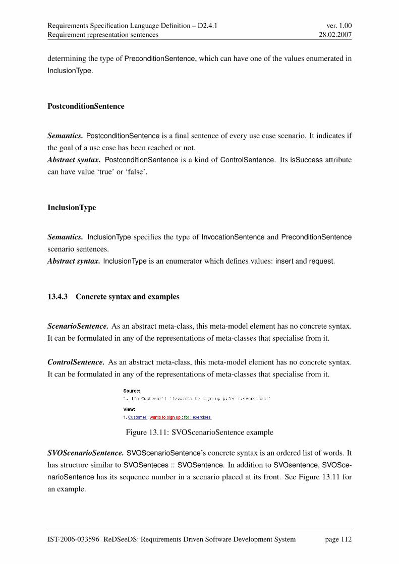
Requirements Specification Language Definition – D2.4.1Requirement representation sentences
ver. 1.0028.02.2007
determining the type of PreconditionSentence, which can have one of the values enumerated inInclusionType.
PostconditionSentence
Semantics. PostconditionSentence is a final sentence of every use case scenario. It indicates ifthe goal of a use case has been reached or not.Abstract syntax. PostconditionSentence is a kind of ControlSentence. Its isSuccess attributecan have value ‘true’ or ‘false’.
InclusionType
Semantics. InclusionType specifies the type of InvocationSentence and PreconditionSentence
scenario sentences.Abstract syntax. InclusionType is an enumerator which defines values: insert and request.
13.4.3 Concrete syntax and examples
ScenarioSentence. As an abstract meta-class, this meta-model element has no concrete syntax.It can be formulated in any of the representations of meta-classes that specialise from it.
ControlSentence. As an abstract meta-class, this meta-model element has no concrete syntax.It can be formulated in any of the representations of meta-classes that specialise from it.
Figure 13.11: SVOScenarioSentence example
SVOScenarioSentence. SVOScenarioSentence’s concrete syntax is an ordered list of words. Ithas structure similar to SVOSenteces :: SVOSentence. In addition to SVOsentence, SVOSce-
narioSentence has its sequence number in a scenario placed at its front. See Figure 13.11 foran example.
IST-2006-033596 ReDSeeDS: Requirements Driven Software Development System page 112
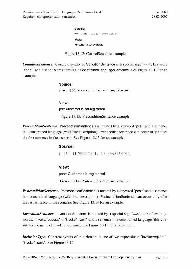
Requirements Specification Language Definition – D2.4.1Requirement representation sentences
ver. 1.0028.02.2007
Figure 13.12: ControlSentence example
ConditionSentence. Concrete syntax of ConditionSentence is a special sign ’==>’, key word’cond:’ and a set of words forming a ConstrainedLanguageSentence. See Figure 13.12 for anexample.
Figure 13.13: PreconditionSentence example
PreconditionSentence. PreconditionSentence’s is notated by a keyword ’pre:’ and a sentencein a constrained language (wiki-like description). PreconditionSentence can occur only beforethe first sentence in the scenario. See Figure 13.13 for an example.
Figure 13.14: PostconditionSentence example
PostconditionSentence. PostconditionSentence is notated by a keyword ’post:’ and a sentencein a constrained language (wiki-like description). PostconditionSentence can occur only afterthe last sentence in the scenario. See Figure 13.14 for an example.
InvocationSentence. InvocationSentence is notated by a special sign ’==>’, one of two key-words: ’invoke/request:’ or’invoke/insert:’ and a sentence in a constrained language (this con-stitutes the name of invoked use case). See Figure 13.15 for an example.
InclusionType. Concrete syntax of this element is one of two expressions: ’invoke/request:’,’invoke/insert:’. See Figure 13.15.
IST-2006-033596 ReDSeeDS: Requirements Driven Software Development System page 113
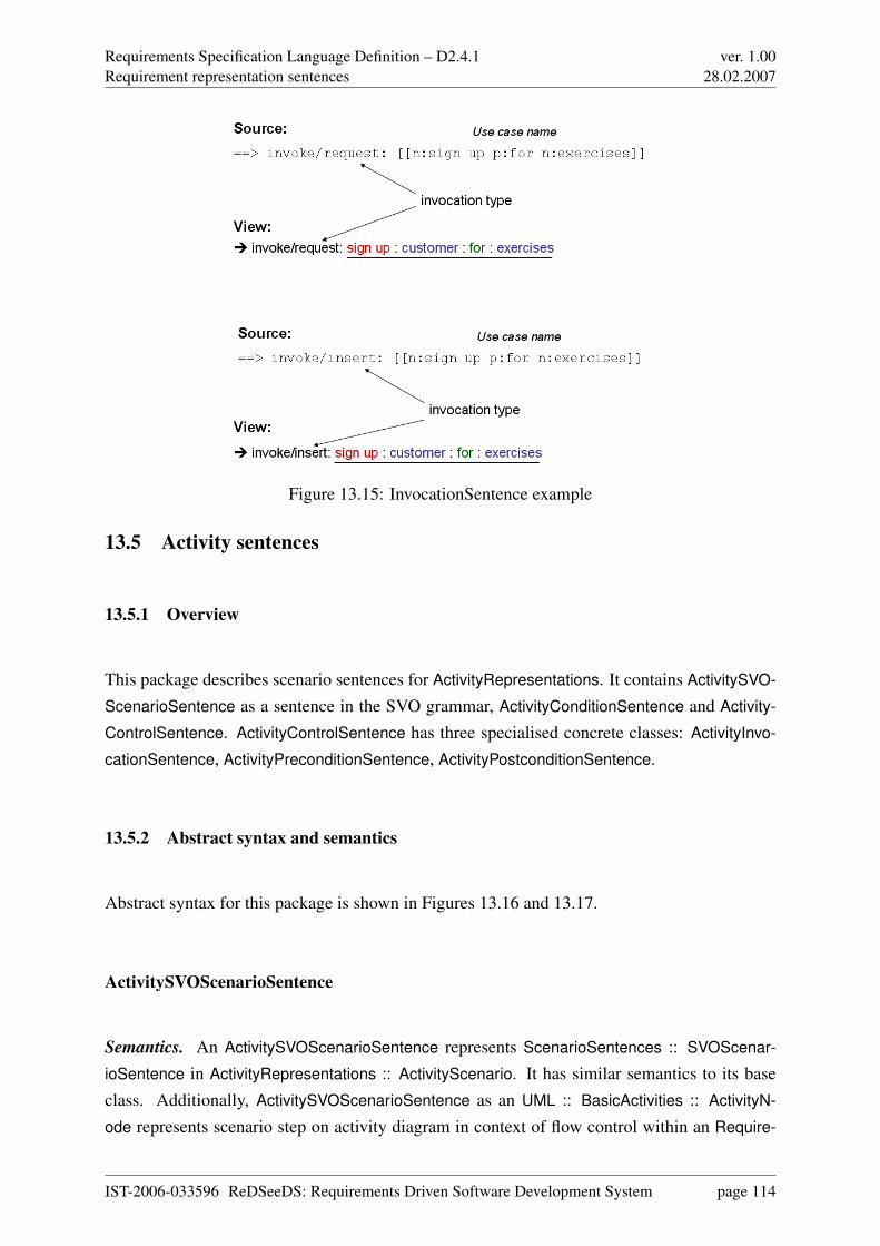
Requirements Specification Language Definition – D2.4.1Requirement representation sentences
ver. 1.0028.02.2007
Figure 13.15: InvocationSentence example
13.5 Activity sentences
13.5.1 Overview
This package describes scenario sentences for ActivityRepresentations. It contains ActivitySVO-
ScenarioSentence as a sentence in the SVO grammar, ActivityConditionSentence and Activity-
ControlSentence. ActivityControlSentence has three specialised concrete classes: ActivityInvo-
cationSentence, ActivityPreconditionSentence, ActivityPostconditionSentence.
13.5.2 Abstract syntax and semantics
Abstract syntax for this package is shown in Figures 13.16 and 13.17.
ActivitySVOScenarioSentence
Semantics. An ActivitySVOScenarioSentence represents ScenarioSentences :: SVOScenar-
ioSentence in ActivityRepresentations :: ActivityScenario. It has similar semantics to its baseclass. Additionally, ActivitySVOScenarioSentence as an UML :: BasicActivities :: ActivityN-
ode represents scenario step on activity diagram in context of flow control within an Require-
IST-2006-033596 ReDSeeDS: Requirements Driven Software Development System page 114
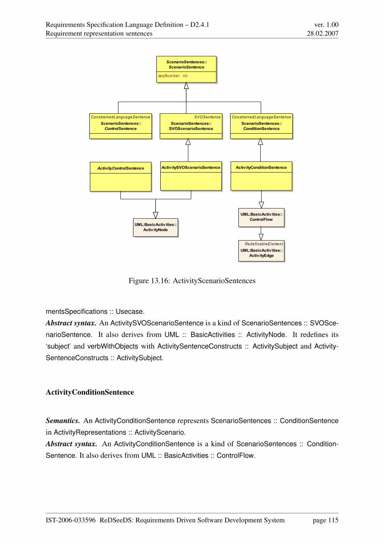
Requirements Specification Language Definition – D2.4.1Requirement representation sentences
ver. 1.0028.02.2007
ScenarioSentences::ScenarioSentence
seqNum ber: in t
Constra inedLanguageSentenceScenarioSentences::ControlSentence
SVOSentenceScenarioSentences::SVOScenarioSentence
UML:BasicActivities::Activ ityNode
RedefinableElementUML:BasicActivities::
Activ ityEdge
UML:BasicActivities::ControlFlow
Constra inedLanguageSentenceScenarioSentences::ConditionSentence
ActivityControlSentence ActivitySVOScenarioSentence Activ ityConditionSentence
Figure 13.16: ActivityScenarioSentences
mentsSpecifications :: Usecase.Abstract syntax. An ActivitySVOScenarioSentence is a kind of ScenarioSentences :: SVOSce-
narioSentence. It also derives from UML :: BasicActivities :: ActivityNode. It redefines its‘subject’ and verbWithObjects with ActivitySentenceConstructs :: ActivitySubject and Activity-
SentenceConstructs :: ActivitySubject.
ActivityConditionSentence
Semantics. An ActivityConditionSentence represents ScenarioSentences :: ConditionSentence
in ActivityRepresentations :: ActivityScenario.Abstract syntax. An ActivityConditionSentence is a kind of ScenarioSentences :: Condition-
Sentence. It also derives from UML :: BasicActivities :: ControlFlow.
IST-2006-033596 ReDSeeDS: Requirements Driven Software Development System page 115
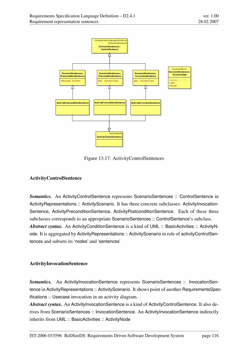
Requirements Specification Language Definition – D2.4.1Requirement representation sentences
ver. 1.0028.02.2007
ScenarioSentences::InvocationSentence
type: InclusionT ype
ScenarioSentences::PostconditionSentence
i sSuccess: boolean
ScenarioSentences::PreconditionSentence
type: InclusionT ype
«enum eration»ScenarioSentences::
InclusionType
«enum »insertrequest
ConstrainedLanguageSentenceScenarioSentence
ScenarioSentences::ControlSentence
Activi tyNodeActivityControlSentence
Activ ityPostconditionSentence Activ ityPreconditionSentence Activ ityInvocationSentence
Figure 13.17: ActivityControlSentences
ActivityControlSentence
Semantics. An ActivityControlSentence represents ScenarioSentences :: ControlSentence inActivityRepresentations :: ActivityScenario. It has three concrete subclasses: ActivityInvocation-
Sentence, ActivityPreconditionSentence, ActivityPostconditionSentence. Each of these threesubclasses corresponds to an appropriate ScenarioSentences :: ControlSentence’s subclass.Abstract syntax. An ActivityConditionSentence is a kind of UML :: BasicActivities :: ActivityN-
ode. It is aggregated by ActivityRepresentations :: ActivityScenario in role of activityControlSen-
tences and subsets its ‘nodes’ and ‘sentences’
ActivityInvocationSentence
Semantics. An ActivityInvocationSentence represents ScenarioSentences :: InvocationSen-
tence in ActivityRepresentations :: ActivityScenario. It shows point of another RequirementsSpec-
ifications :: Usecase invocation in an activity diagram.Abstract syntax. An ActivityInvocationSentence is a kind of ActivityControlSentence. It also de-rives from ScenarioSentences :: InvocationSentence. An ActivityInvocationSentence indirectlyinherits from UML :: BasicActivities :: ActivityNode
IST-2006-033596 ReDSeeDS: Requirements Driven Software Development System page 116
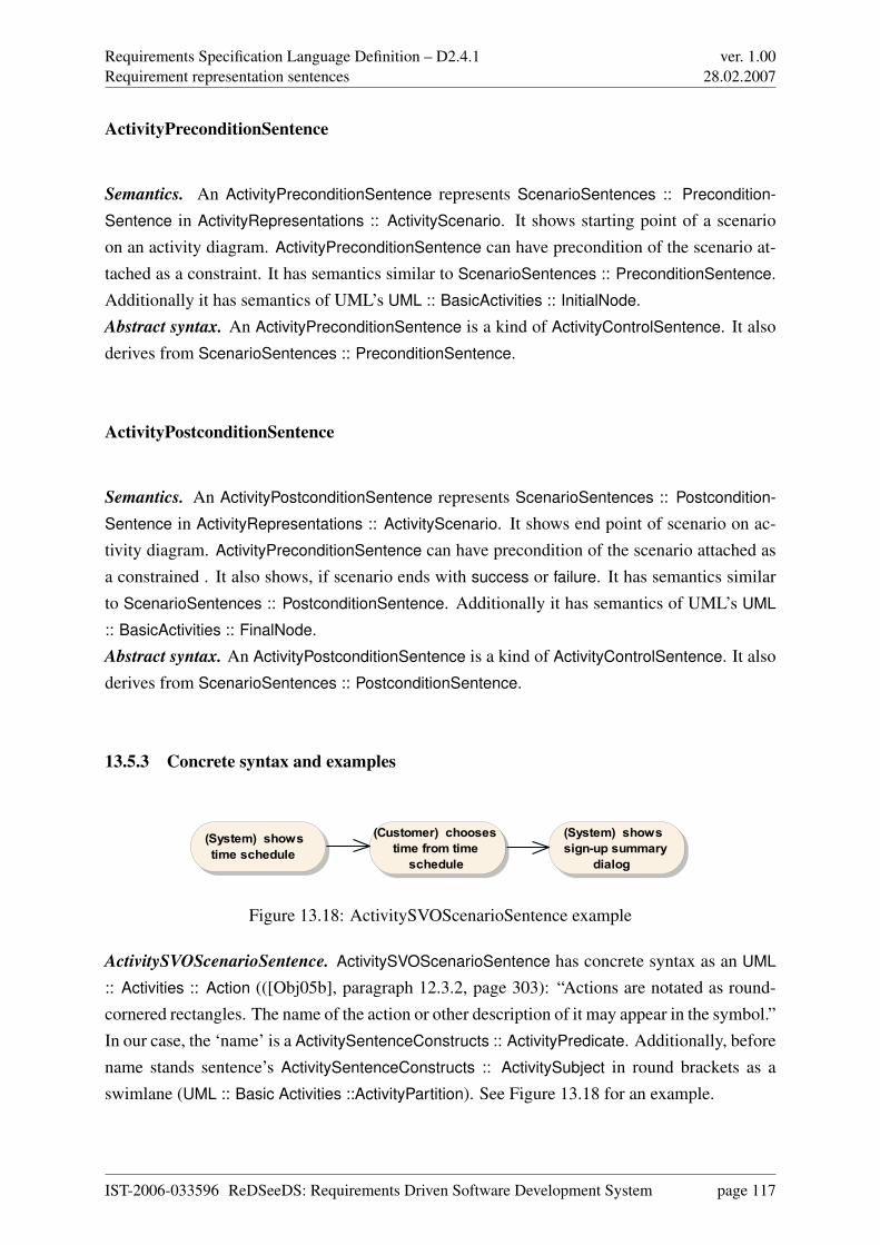
Requirements Specification Language Definition – D2.4.1Requirement representation sentences
ver. 1.0028.02.2007
ActivityPreconditionSentence
Semantics. An ActivityPreconditionSentence represents ScenarioSentences :: Precondition-
Sentence in ActivityRepresentations :: ActivityScenario. It shows starting point of a scenarioon an activity diagram. ActivityPreconditionSentence can have precondition of the scenario at-tached as a constraint. It has semantics similar to ScenarioSentences :: PreconditionSentence.Additionally it has semantics of UML’s UML :: BasicActivities :: InitialNode.Abstract syntax. An ActivityPreconditionSentence is a kind of ActivityControlSentence. It alsoderives from ScenarioSentences :: PreconditionSentence.
ActivityPostconditionSentence
Semantics. An ActivityPostconditionSentence represents ScenarioSentences :: Postcondition-
Sentence in ActivityRepresentations :: ActivityScenario. It shows end point of scenario on ac-tivity diagram. ActivityPreconditionSentence can have precondition of the scenario attached asa constrained . It also shows, if scenario ends with success or failure. It has semantics similarto ScenarioSentences :: PostconditionSentence. Additionally it has semantics of UML’s UML
:: BasicActivities :: FinalNode.Abstract syntax. An ActivityPostconditionSentence is a kind of ActivityControlSentence. It alsoderives from ScenarioSentences :: PostconditionSentence.
13.5.3 Concrete syntax and examples
(System) shows time schedule
(System) shows sign-up summary
dialog
(Customer) chooses time from time
schedule
Figure 13.18: ActivitySVOScenarioSentence example
ActivitySVOScenarioSentence. ActivitySVOScenarioSentence has concrete syntax as an UML
:: Activities :: Action (([Obj05b], paragraph 12.3.2, page 303): “Actions are notated as round-cornered rectangles. The name of the action or other description of it may appear in the symbol.”In our case, the ‘name’ is a ActivitySentenceConstructs :: ActivityPredicate. Additionally, beforename stands sentence’s ActivitySentenceConstructs :: ActivitySubject in round brackets as aswimlane (UML :: Basic Activities ::ActivityPartition). See Figure 13.18 for an example.
IST-2006-033596 ReDSeeDS: Requirements Driven Software Development System page 117
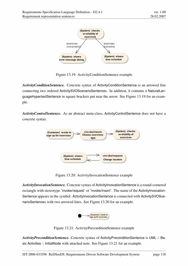
Requirements Specification Language Definition – D2.4.1Requirement representation sentences
ver. 1.0028.02.2007
(System) shows time schedule
(System) checks availabilty of
exercices
(System) shows error message dialog
[exercisesavai lable]
[exercicesunavai lable]
Figure 13.19: ActivityConditionSentence example
ActivityConditionSentence. Concrete syntax of ActivityConditionSentence is an arrowed lineconnecting two ordered ActivitySVOScenarioSentences. In addition, it contains a NaturalLan-
guageHypertextSentence in square brackets put near the arrow. See Figure 13.19 for an exam-ple.
ActivityControlSentence. As an abstract meta-class, ActivityControlSentence does not have aconcrete syntax.
(System) checks availabilty of
exercices
«invoke/insert»Choose exercises
type
(Customer) wants to sign up for exercises
(System) shows time schedule
«invoke/request»Change location
Figure 13.20: ActivityInvocationSentence example
ActivityInvocationSentence. Concrete syntax of ActivityInvocationSentence is a round-corneredrectangle with stereotype ’invoke/request’ or ’invoke/insert’. The name of the ActivityInvocation-
Sentence appears in the symbol. ActivityInvocationSentence is connected with ActivitySVOSce-
narioSentences with two arrowed lines. See Figure 13.20 for an example.
«...
(Customer) wants to sign up for exercises
Figure 13.21: ActivityPreconditionSentence example
ActivityPreconditionSentence. Concrete syntax of ActivityPreconditionSentence is UML :: Ba-
sic Activities :: InitialNode with attached note. See Figure 13.21 for an example.
IST-2006-033596 ReDSeeDS: Requirements Driven Software Development System page 118
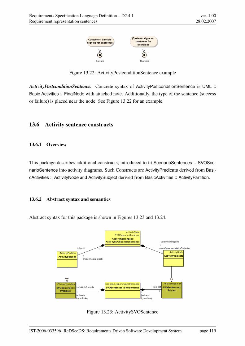
Requirements Specification Language Definition – D2.4.1Requirement representation sentences
ver. 1.0028.02.2007
«...Fa i lure
(Customer) cancels sign up for exercices
«...Success
(System) signs up customer for
exercices
Figure 13.22: ActivityPostconditionSentence example
ActivityPostconditionSentence. Concrete syntax of ActivityPostconditionSentence is UML ::
Basic Activities :: FinalNode with attached note. Additionally, the type of the sentence (successor failure) is placed near the node. See Figure 13.22 for an example.
13.6 Activity sentence constructs
13.6.1 Overview
This package describes additional constructs, introduced to fit ScenarioSentences :: SVOSce-
narioSentence into activity diagrams. Such Constructs are ActivityPredicate derived from Basi-
cActivities :: ActivityNode and ActivitySubject derived from BasicActivities :: ActivityPartition.
13.6.2 Abstract syntax and semantics
Abstract syntax for this package is shown in Figures 13.23 and 13.24.
Activi tyNodeSVOScenarioSentence
Activ itySentences::Activ itySVOScenarioSentence
Activi tyParti tionActivitySubject
Activi tyNodeActiv ityPredicate
PhraseHyperl inkSVOSentences::
Predicate
Constra inedLanguageSentenceSVOSentences::SVOSentence
PhraseHyperl inkSVOSentences::
Subject
verbsWi thObjects1{redefines verbsWi thObjects}1subject
1{redefines subject}
1
verbWi thObjects
1{subsetshyperl inks}
1
sub ject
1{subsetshyperl inks}
1
Figure 13.23: ActivitySVOSentence
IST-2006-033596 ReDSeeDS: Requirements Driven Software Development System page 119
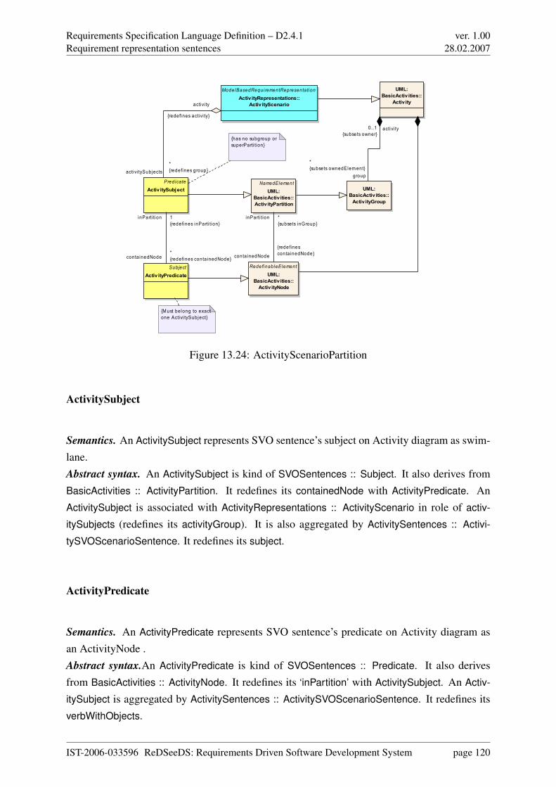
Requirements Specification Language Definition – D2.4.1Requirement representation sentences
ver. 1.0028.02.2007
ModelBasedRequi rementRepresentationActivityRepresentations::
Activ ityScenario
Pred icateActivitySubject
UML:BasicActiv ities::
Activ ity
UML:BasicActiv ities::Activ ityGroup
NamedElementUML:
BasicActiv ities::Activ ityPartition
SubjectActivityPredicate
RedefinableElementUML:
BasicActiv ities::Activ ityNode
{has no subgroup or superParti tion}
{M ust belong to exact one Activi tySubject}
activi tySubjects*{redefines group}
activi ty
{redefines activi ty}
group
*{subsets ownedElem ent}
activi ty0..1{subsets owner}
inParti tion 1{redefines inParti tion}
conta inedNode*{redefines conta inedNode}
inParti tion *{subsets inGroup}
conta inedNode
{redefinesconta inedNode}
Figure 13.24: ActivityScenarioPartition
ActivitySubject
Semantics. An ActivitySubject represents SVO sentence’s subject on Activity diagram as swim-lane.Abstract syntax. An ActivitySubject is kind of SVOSentences :: Subject. It also derives fromBasicActivities :: ActivityPartition. It redefines its containedNode with ActivityPredicate. AnActivitySubject is associated with ActivityRepresentations :: ActivityScenario in role of activ-
itySubjects (redefines its activityGroup). It is also aggregated by ActivitySentences :: Activi-
tySVOScenarioSentence. It redefines its subject.
ActivityPredicate
Semantics. An ActivityPredicate represents SVO sentence’s predicate on Activity diagram asan ActivityNode .Abstract syntax.An ActivityPredicate is kind of SVOSentences :: Predicate. It also derivesfrom BasicActivities :: ActivityNode. It redefines its ‘inPartition’ with ActivitySubject. An Activ-
itySubject is aggregated by ActivitySentences :: ActivitySVOScenarioSentence. It redefines itsverbWithObjects.
IST-2006-033596 ReDSeeDS: Requirements Driven Software Development System page 120
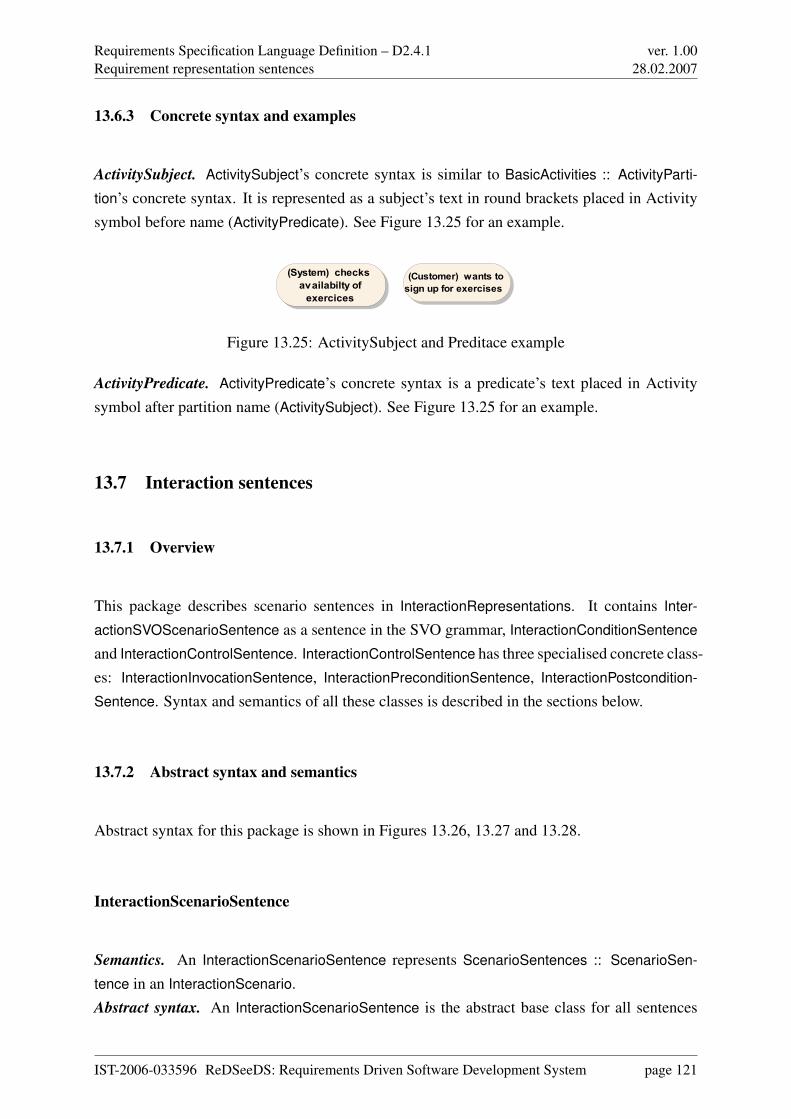
Requirements Specification Language Definition – D2.4.1Requirement representation sentences
ver. 1.0028.02.2007
13.6.3 Concrete syntax and examples
ActivitySubject. ActivitySubject’s concrete syntax is similar to BasicActivities :: ActivityParti-
tion’s concrete syntax. It is represented as a subject’s text in round brackets placed in Activitysymbol before name (ActivityPredicate). See Figure 13.25 for an example.
(Customer) wants to sign up for exercises
(System) checks availabilty of
exercices
Figure 13.25: ActivitySubject and Preditace example
ActivityPredicate. ActivityPredicate’s concrete syntax is a predicate’s text placed in Activitysymbol after partition name (ActivitySubject). See Figure 13.25 for an example.
13.7 Interaction sentences
13.7.1 Overview
This package describes scenario sentences in InteractionRepresentations. It contains Inter-
actionSVOScenarioSentence as a sentence in the SVO grammar, InteractionConditionSentence
and InteractionControlSentence. InteractionControlSentence has three specialised concrete class-es: InteractionInvocationSentence, InteractionPreconditionSentence, InteractionPostcondition-
Sentence. Syntax and semantics of all these classes is described in the sections below.
13.7.2 Abstract syntax and semantics
Abstract syntax for this package is shown in Figures 13.26, 13.27 and 13.28.
InteractionScenarioSentence
Semantics. An InteractionScenarioSentence represents ScenarioSentences :: ScenarioSen-
tence in an InteractionScenario.Abstract syntax. An InteractionScenarioSentence is the abstract base class for all sentences
IST-2006-033596 ReDSeeDS: Requirements Driven Software Development System page 121
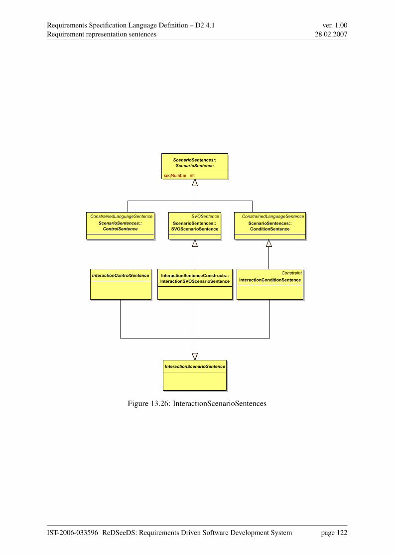
Requirements Specification Language Definition – D2.4.1Requirement representation sentences
ver. 1.0028.02.2007
ScenarioSentences::
ScenarioSentence
seqNumber: int
ConstrainedLanguageSentence
ScenarioSentences::
ControlSentence
SVOSentence
ScenarioSentences::
SVOScenarioSentence
ConstrainedLanguageSentence
ScenarioSentences::
ConditionSentence
InteractionControlSentenceConstraint
InteractionConditionSentence
InteractionSentenceConstructs::
InteractionSVOScenarioSentence
InteractionScenarioSentence
Figure 13.26: InteractionScenarioSentences
IST-2006-033596 ReDSeeDS: Requirements Driven Software Development System page 122
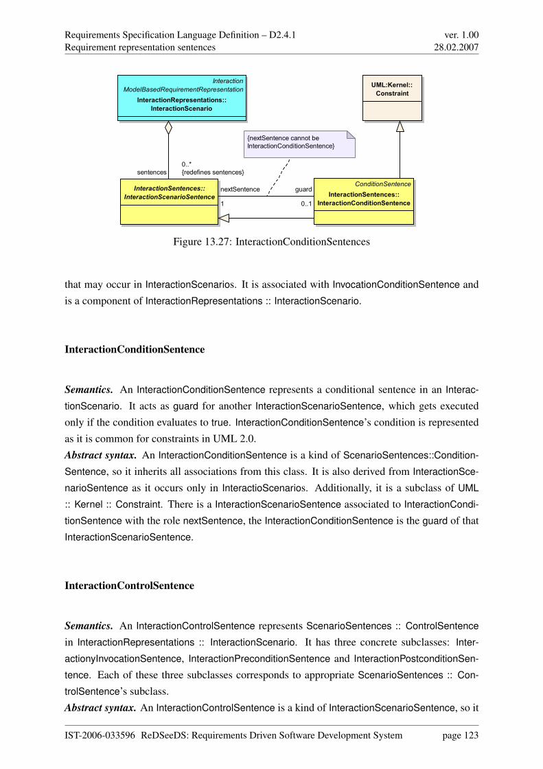
Requirements Specification Language Definition – D2.4.1Requirement representation sentences
ver. 1.0028.02.2007
ConditionSentence
InteractionSentences::
InteractionConditionSentence
Interaction
ModelBasedRequirementRepresentation
InteractionRepresentations::
InteractionScenario
InteractionSentences::
InteractionScenarioSentence
UML:Kernel::
Constraint
{nextSentence cannot be
InteractionConditionSentence}
guard
0..1
nextSentence
1
sentences
0..*
{redefines sentences}
Figure 13.27: InteractionConditionSentences
that may occur in InteractionScenarios. It is associated with InvocationConditionSentence andis a component of InteractionRepresentations :: InteractionScenario.
InteractionConditionSentence
Semantics. An InteractionConditionSentence represents a conditional sentence in an Interac-
tionScenario. It acts as guard for another InteractionScenarioSentence, which gets executedonly if the condition evaluates to true. InteractionConditionSentence’s condition is representedas it is common for constraints in UML 2.0.Abstract syntax. An InteractionConditionSentence is a kind of ScenarioSentences::Condition-
Sentence, so it inherits all associations from this class. It is also derived from InteractionSce-
narioSentence as it occurs only in InteractioScenarios. Additionally, it is a subclass of UML
:: Kernel :: Constraint. There is a InteractionScenarioSentence associated to InteractionCondi-
tionSentence with the role nextSentence, the InteractionConditionSentence is the guard of thatInteractionScenarioSentence.
InteractionControlSentence
Semantics. An InteractionControlSentence represents ScenarioSentences :: ControlSentence
in InteractionRepresentations :: InteractionScenario. It has three concrete subclasses: Inter-
actionyInvocationSentence, InteractionPreconditionSentence and InteractionPostconditionSen-
tence. Each of these three subclasses corresponds to appropriate ScenarioSentences :: Con-
trolSentence’s subclass.Abstract syntax. An InteractionControlSentence is a kind of InteractionScenarioSentence, so it
IST-2006-033596 ReDSeeDS: Requirements Driven Software Development System page 123
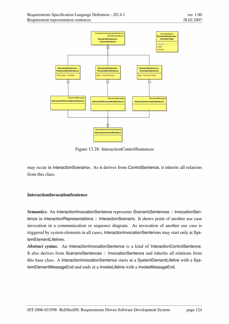
Requirements Specification Language Definition – D2.4.1Requirement representation sentences
ver. 1.0028.02.2007
ScenarioSentences::
InvocationSentence
type: InclusionType
ScenarioSentences::
PostconditionSentence
isSuccess: boolean
ScenarioSentences::
PreconditionSentence
type: InclusionType
«enumeration»
ScenarioSentences::
InclusionType
«enum»
insert
request
ConstrainedLanguageSentence
ScenarioSentence
ScenarioSentences::
ControlSentence
ScenarioMessage
InteractionPostconditionSentence
ScenarioMessage
InteractionPreconditionSentence
ScenarioMessage
InteractionInvocationSentence
InteractionScenarioSentence
InteractionControlSentence
Figure 13.28: InteractionControlSentences
may occur in InteractionScenarios. As it derives from ControlSentence, it inherits all relationsfrom this class.
InteractionInvocationSentence
Semantics. An InteractionInvocationSentence represents ScenarioSentences :: InvocationSen-
tence in InteractionRepresentations :: InteractionScenario. It shows point of another use caseinvocation in a communication or sequence diagram. As invocation of another use case istriggered by system elements in all cases, InteractionInvocationSentences may start only at Sys-
temElementLifelines.Abstract syntax. An InteractionInvocationSentence is a kind of InteractionControlSentence.It also derives from ScenarioSentences :: InvocationSentence and inherits all relations fromthis base class. A InteractionInvocationSentence starts at a SystemElementLifeline with a Sys-
temElementMessageEnd and ends at a InvokeLifeline with a InvokeMessageEnd.
IST-2006-033596 ReDSeeDS: Requirements Driven Software Development System page 124
Requirements Specification Language Definition – D2.4.1Requirement representation sentences
ver. 1.0028.02.2007
InteractionPreconditionSentence
Semantics. An InteractionPreconditionSentence represents ScenarioSentences :: Interaction-
Sentence in InteractionRepresentations :: InteractionScenario. It shows the entrypoint of thescenario represented by an interaction diagram. A constraint may be attached to a Interaction-
PreconditionSentence serving as a precondition of the scenario. It has semantics similar toScenarioSentences :: PreconditionSentence.Abstract syntax. An InteractionPreconditionSentence is a kind of InteractionControlSentence.It also derives from ScenarioSentences :: PreconditionSentence. It is associated with Interac-
tionSentenceConstructs :: ActorMessageEnd.
InteractionPostconditionSentence
Semantics. An InteractionPostconditionSentence represents ScenarioSentences :: Postcondi-
tionSentence in a scenario description by InteractionRepresentations :: InteractionScenario. Itshows the end point of a scenario represented by an interaction diagram. Similar to Interac-
tionPreconditionSentence, a constraint may be attached to InteractionPostconditionSentence,serving as a postcondition of the described scenario. Additionally, InteractionPostconditionSen-
tence shows, if the scenario ends with success or failure. Further semantics of InteractionPost-
conditionSentence is similar to ScenarioSentences :: PostconditionSentence.Abstract syntax. An InteractionPostconditionSentence is a kind of InteractionControlSentence.It also derives from ScenarioSentences :: PostconditionSentence. It is associated with Interac-
tionSentenceConstructs :: ActorMessageEnd.
13.7.3 Concrete syntax and examples
This section describes concrete syntax for the sentences described in the section above usingthe figures 13.29 and 13.30 known from section 12.6 as examples.
InteractionScenarioSentence This class is abstract, so there is no concrete syntax.
InteractionConditionSentence In interaction diagrams used for describing scenarios, condi-tional sentences are represented as a condition at the next message in the scenario. A exampleis shown in figure 13.29 at the message “acceptHelpRequest”. The condition for this sentenceshould be put in curly brackets nearby the line representing the message with role nextSentence
IST-2006-033596 ReDSeeDS: Requirements Driven Software Development System page 125
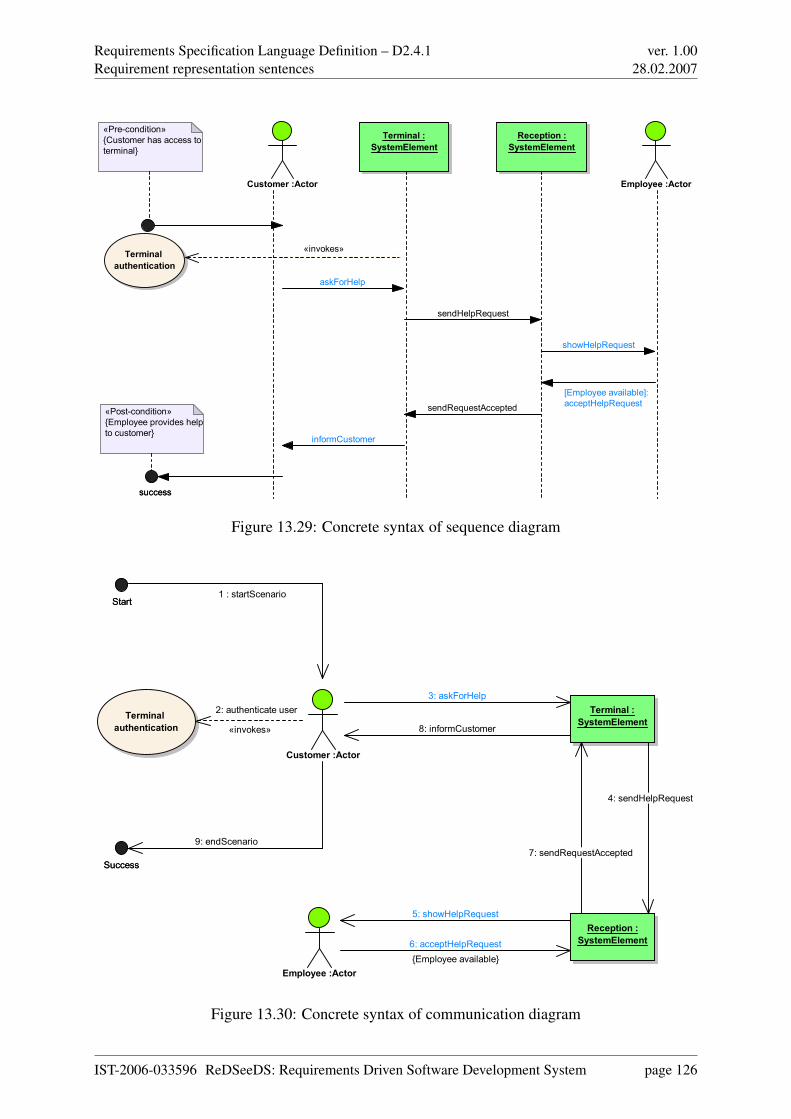
Requirements Specification Language Definition – D2.4.1Requirement representation sentences
ver. 1.0028.02.2007
Terminal :
SystemElement
Reception :
SystemElement
Customer :Actor Employee :Actor
successsuccess
«Pre-condition»
{Customer has access to
terminal}
Terminal
authentication
«Post-condition»
{Employee provides help
to customer}
«invokes»
askForHelp
sendHelpRequest
showHelpRequest
[Employee available]:
acceptHelpRequestsendRequestAccepted
informCustomer
Figure 13.29: Concrete syntax of sequence diagram
Customer :Actor
Reception :
SystemElement
Terminal :
SystemElement
Employee :Actor
Terminal
authentication
StartStart
SuccessSuccess
1 : startScenario
6: acceptHelpRequest
{Employee available}
4: sendHelpRequest
8: informCustomer
5: showHelpRequest
7: sendRequestAccepted
9: endScenario
2: authenticate user
«invokes»
3: askForHelp
Figure 13.30: Concrete syntax of communication diagram
IST-2006-033596 ReDSeeDS: Requirements Driven Software Development System page 126
Requirements Specification Language Definition – D2.4.1Requirement representation sentences
ver. 1.0028.02.2007
in the abstract syntax. In communication diagram the notation is similar to this, as messagenumber 6 in Figure 13.30 shows.
InteractionControlSentence This class is abstract, so there is no concrete syntax.
InteractionInvocationSentence An InteractionInvocationSentence is modelled by a messagestarting at a lifeline and ending at a use case oval. This use case is the one the InteractionInvo-
cationSentence invokes. The message left in figure 13.29 shows an example of InteractionIn-
vocationSentence’s concrete syntax. The use case called Terminal authentication is included inthe scenario description using a message from the main actors lifeline to the use case diagramelement. In figure 13.30, the same sentence is represented by message with number 2.
InteractionPreconditionSentence InteractionPrecondiationSentences are modelled as shown inthe upper left corner of figure 13.29. An initial point represents the start of the scenario, theprecondition is attached to this initial point as a UML constraint. In figure 13.30, the samesentence is represented by message with number 1.
InteractionPostconditionSentence The representation of InteractionPostconditionSentence issimilar to the one of InteractionPreconditionSentence. A end point is used to represent the endof the scenario, the postcondiation is, analogous to the precondition of InteractionPrecondition-
Sentence, modelled as a UML constraint attached to the end point. In figure 13.30, the samesentence is represented by message with number 10.
13.8 Interaction sentence constructs
13.8.1 Overview
Sections 12.6 and 13.7 have described the concept of InteractionScenario and the different sen-tence types that may be used in such scenario representations. This section explains the remain-ing elements of InteractionScenarios, such as different types of lifelines, messages and relationsbetween them.
13.8.2 Abstract syntax and semantics
The abstract syntax for this package is shown in figures 13.31 to 13.35.
IST-2006-033596 ReDSeeDS: Requirements Driven Software Development System page 127
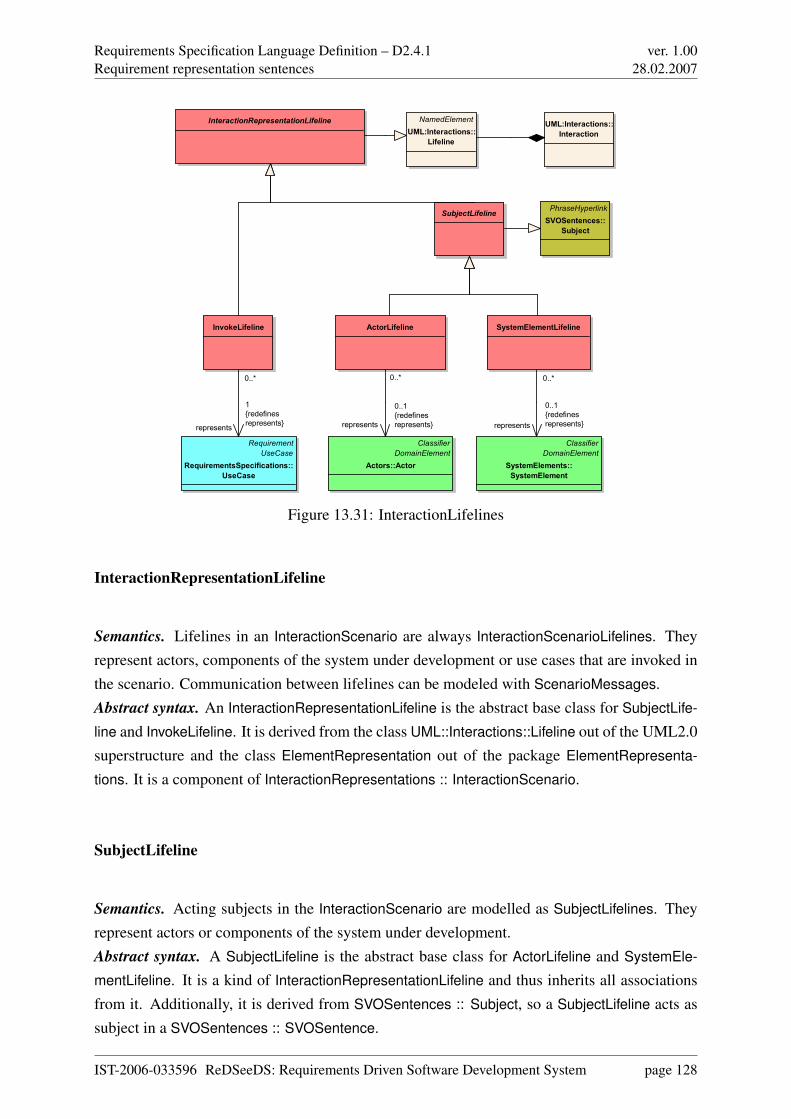
Requirements Specification Language Definition – D2.4.1Requirement representation sentences
ver. 1.0028.02.2007
UML:Interactions::
Interaction
NamedElement
UML:Interactions::
Lifeline
ActorLifeline SystemElementLifeline
InteractionRepresentationLifeline
InvokeLifeline
SubjectLifeline
Classifier
DomainElement
Actors::Actor
Classifier
DomainElement
SystemElements::
SystemElement
PhraseHyperlink
SVOSentences::
Subject
Requirement
UseCase
RequirementsSpecifications::
UseCase
0..*
represents
0..1
{redefines
represents}
0..*
represents
0..1
{redefines
represents}
0..*
represents
1
{redefines
represents}
Figure 13.31: InteractionLifelines
InteractionRepresentationLifeline
Semantics. Lifelines in an InteractionScenario are always InteractionScenarioLifelines. Theyrepresent actors, components of the system under development or use cases that are invoked inthe scenario. Communication between lifelines can be modeled with ScenarioMessages.Abstract syntax. An InteractionRepresentationLifeline is the abstract base class for SubjectLife-
line and InvokeLifeline. It is derived from the class UML::Interactions::Lifeline out of the UML2.0superstructure and the class ElementRepresentation out of the package ElementRepresenta-
tions. It is a component of InteractionRepresentations :: InteractionScenario.
SubjectLifeline
Semantics. Acting subjects in the InteractionScenario are modelled as SubjectLifelines. Theyrepresent actors or components of the system under development.Abstract syntax. A SubjectLifeline is the abstract base class for ActorLifeline and SystemEle-
mentLifeline. It is a kind of InteractionRepresentationLifeline and thus inherits all associationsfrom it. Additionally, it is derived from SVOSentences :: Subject, so a SubjectLifeline acts assubject in a SVOSentences :: SVOSentence.
IST-2006-033596 ReDSeeDS: Requirements Driven Software Development System page 128
Requirements Specification Language Definition – D2.4.1Requirement representation sentences
ver. 1.0028.02.2007
ActorLifeline
Semantics. Every actor who participates in a scenario described by a InteractionScenario isrepresented by an ActorLifeline. Since the scenario models an interaction between an actor andparts of the system, every ActorLifeline can have some outgoing and incoming messages.Abstract syntax. An ActorLifeline is a kind of SubjectLifeline, so it may act as subject in aSVOSentence. An ActorLifeline may cover zero or more ActorMessageEnds, this associationredefines the inherited association between Lifeline and MessageEnd. Each ActorLifeline is therepresentation of one Actors :: Actor, which is in represents role to ActorLifeline. An ActorLife-
line can associated with InteractionRepresentations :: InteractionScenarios as a primaryActor. Itis also a component of InteractionRepresentations :: InteractionScenario.
SystemElementLifeline
Semantics. A SystemElementLifeline is similar to ActorLifeline with the difference, that it rep-resents components of the system under development instead of actors. Depending on the levelof granularity the requirements engineer chose, the whole system can be modeled as one singlecomponent. Also communications between different system components or between a systemcomponent and an actor are represented as outgoing and incoming messages.Abstract syntax. An SystemElementLifeline is a kind of SubjectLifeline, so it may act as subjectin a SVOSentence similar to ActorLifeline. Each SystemElementLifeline is the representation ofone SystemElements :: SystemElement, which is in represents role to SystemElementLifeline.It may cover SystemElementMessageEnds, the association describing this fact redefines theinherited association between Lifeline and MessageEnd in almost the same manner as it is donefor ActorLifeline. SystemElementLifeline is also a component of InteractionRepresentations ::
InteractionScenario.
InvokeLifeline
Semantics. InvokeLifelines represent use cases that are invoked in a scenario. So use cases thatare needed more than once can be used in different scenarios easily and separation of concersis possible.Abstract syntax. InvokeLifeline is derived from InteractionRepresentationLifeline and representsvia association exact one RequirementsSpecifications :: UseCase, while a RequirementsSpe-
cifications :: UseCase can be represented by more than one invoke lifelines, as the multiplicities
IST-2006-033596 ReDSeeDS: Requirements Driven Software Development System page 129
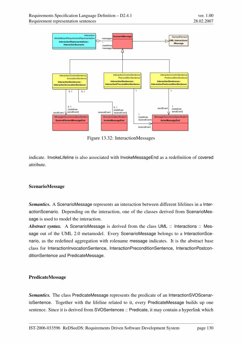
Requirements Specification Language Definition – D2.4.1Requirement representation sentences
ver. 1.0028.02.2007
Interaction
ModelBasedRequirementRepresentation
InteractionRepresentations::
InteractionScenario
NamedElement
UML:Interactions:
:Message
ScenarioMessage
InteractionControlSentence
InvocationSentence
InteractionSentences::
InteractionInvocationSentence
InteractionControlSentence
PostconditionSentence
InteractionSentences::
InteractionPostconditionSentence
InteractionControlSentence
PreconditionSentence
InteractionSentences::
InteractionPreconditionSentence
MessageOccurrenceSpecification
ActorMessageEnd
OccurenceSpecification
InvokeMessageEnd
MessageOccurrenceSpecification
SystemElementMessageEnd
messages
*
{redefines
message}
1
sendEvent1
{redefines
sendEvent}
1
receiveEvent
1
{redefines
receiveEvent}
receiveEvent
0..1
{redefines
receiveEvent}
0..1
sendEvent
0..1
{redefines
sendEvent}
0..1
Figure 13.32: InteractionMessages
indicate. InvokeLifeline is also associated with InvokeMessageEnd as a redefinition of covered
attribute.
ScenarioMessage
Semantics. A ScenarioMessage represents an interaction between different lifelines in a Inter-
actionScenario. Depending on the interaction, one of the classes derived from ScenarioMes-
sage is used to model the interaction.Abstract syntax. A ScenarioMessage is derived from the class UML :: Interactions :: Mes-
sage out of the UML 2.0 metamodel. Every ScenarioMessage belongs to a InteractionSce-
nario, as the redefined aggregation with rolename message indicates. It is the abstract baseclass for InteractionInvocationSentence, InteractionPreconditionSentence, InteractionPostcon-
ditionSentence and PredicateMessage.
PredicateMessage
Semantics. The class PredicateMessage represents the predicate of an InteractionSVOScenar-
ioSentence. Together with the lifeline related to it, every PredicateMessage builds up onesentence. Since it is derived from SVOSentences :: Predicate, it may contain a hyperlink which
IST-2006-033596 ReDSeeDS: Requirements Driven Software Development System page 130
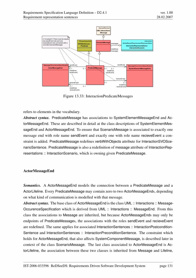
Requirements Specification Language Definition – D2.4.1Requirement representation sentences
ver. 1.0028.02.2007
Interaction
ModelBasedRequirementRepresentation
InteractionRepresentations::
InteractionScenario
PredicateMessage
NamedElement
UML:Interactions:
:Message
MessageOccurrenceSpecification
ActorMessageEnd
MessageOccurrenceSpecification
SystemElementMessageEnd
{<<invariant>>There must be exactly
one sendEvent role and one
recieveEvent role connected with a
concrete ScenarioMessage}
PhraseHyperlink
SVOSentences::
Predicate
ScenarioMessage
0..1
sendEvent
0..1
{redefines
sendEvent}
0..1
recieveEvent
0..1
{redefines
recieveEvent}
0..1
recieveEvent
0..1
{redefines
recieveEvent}
0..1
sendEvent
0..1
{redefines
sendEvent}
messages
*
{redefines
message}
Figure 13.33: InteractionPredicateMessages
refers to elements in the vocabulary.Abstract syntax. PredicateMessage has associations to SystemElementMessageEnd and Ac-
torMessageEnd. These are described in detail at the class descriptions of SystemElementMes-
sageEnd and ActorMessageEnd. To ensure that ScenarioMessage is associated to exactly onemessage end with role name sendEvent and exactly one with role name recieveEvent a con-straint is added. PredicateMessage redefines verbWithObjects attribute for InteractionSVOSce-
narioSentence. PredicateMessage is also a redefinition of message attribute of InteractionRep-
resentations :: InteractionScenario, which is owning given PredicateMessage.
ActorMessageEnd
Semantics. A ActorMessageEnd models the connection between a PredicateMessage and aActorLifeline. Every PredicateMessage may contain zero to two ActorMessageEnds, dependingon what kind of communication is modelled with that message.Abstract syntax. The base class of ActorMessageEnd is the class UML :: Interactions :: Message-
OccurenceSpecification which is derived from UML :: Interactions :: MessageEnd. From thisclass the associations to Message are inherited, but because ActorMessageEnds may only beendpoints of PredicateMessages, the associations with the roles sendEvent and recieveEvent
are redefined. The same applies for associated InteractionSentences :: InteractionPostcondition-
Sentence and InteractionSentences :: InteractionPreconditionSentence. The constraint whichholds for ActorMessageEnd, that also affects SystemComponentMessage, is described later incontext of the class ScenarioMessage. The last class associated to ActorMessageEnd is Ac-
torLifeline, the association between these two classes is inherited from Message and Lifeline,
IST-2006-033596 ReDSeeDS: Requirements Driven Software Development System page 131
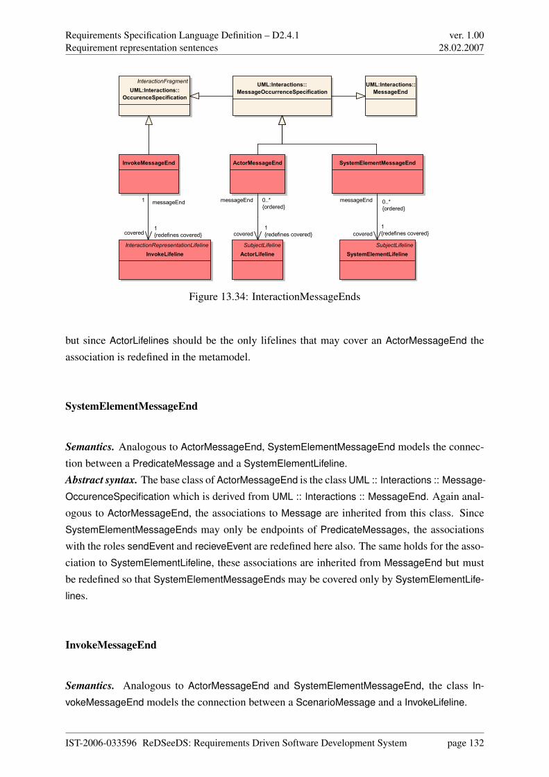
Requirements Specification Language Definition – D2.4.1Requirement representation sentences
ver. 1.0028.02.2007
UML:Interactions::
MessageEnd
UML:Interactions::
MessageOccurrenceSpecification
InteractionFragment
UML:Interactions::
OccurenceSpecification
SubjectLifeline
ActorLifeline
ActorMessageEnd
InteractionRepresentationLifeline
InvokeLifeline
InvokeMessageEnd
SubjectLifeline
SystemElementLifeline
SystemElementMessageEnd
messageEnd 0..*
{ordered}
covered1
{redefines covered}
messageEnd1
covered1
{redefines covered}
messageEnd 0..*
{ordered}
covered
1
{redefines covered}
Figure 13.34: InteractionMessageEnds
but since ActorLifelines should be the only lifelines that may cover an ActorMessageEnd theassociation is redefined in the metamodel.
SystemElementMessageEnd
Semantics. Analogous to ActorMessageEnd, SystemElementMessageEnd models the connec-tion between a PredicateMessage and a SystemElementLifeline.Abstract syntax. The base class of ActorMessageEnd is the class UML :: Interactions :: Message-
OccurenceSpecification which is derived from UML :: Interactions :: MessageEnd. Again anal-ogous to ActorMessageEnd, the associations to Message are inherited from this class. SinceSystemElementMessageEnds may only be endpoints of PredicateMessages, the associationswith the roles sendEvent and recieveEvent are redefined here also. The same holds for the asso-ciation to SystemElementLifeline, these associations are inherited from MessageEnd but mustbe redefined so that SystemElementMessageEnds may be covered only by SystemElementLife-
lines.
InvokeMessageEnd
Semantics. Analogous to ActorMessageEnd and SystemElementMessageEnd, the class In-
vokeMessageEnd models the connection between a ScenarioMessage and a InvokeLifeline.
IST-2006-033596 ReDSeeDS: Requirements Driven Software Development System page 132
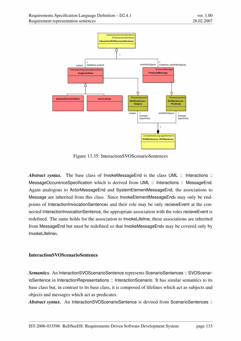
Requirements Specification Language Definition – D2.4.1Requirement representation sentences
ver. 1.0028.02.2007
ActorLifelineSystemElementLifeline
ScenarioMessage
PredicateMessage
PhraseHyperlink
SVOSentences::
Predicate
ConstrainedLanguageSentence
SVOSentences::SVOSentence
PhraseHyperlink
SVOSentences::
Subject
InteractionScenarioSentence
SVOScenarioSentence
InteractionSVOScenarioSentence
InteractionRepresentationLifeline
SubjectLifeline
verbWithObjects1
{redefines verbWithObjects}
1
verbWithObjects 1
{subsets
hyperlinks}
1
subject 1
{subsets
hyperlinks}
1
subject
1
{redefines subject}
1
Figure 13.35: InteractionSVOScenarioSentences
Abstract syntax. The base class of InvokeMessageEnd is the class UML :: Interactions ::
MessageOccurenceSpecification which is derived from UML :: Interactions :: MessageEnd.Again analogous to ActorMessageEnd and SystemElementMessageEnd, the associations toMessage are inherited from this class. Since InvokeElementMessageEnds may only be end-points of InteractionInvocationSentences and their role may be only recieveEvent at the con-nected InteractionInvocationSentence, the appropriate association with the roles recieveEvent isredefined. The same holds for the association to InvokeLifeline, these associations are inheritedfrom MessageEnd but must be redefined so that InvokeMessageEnds may be covered only byInvokeLifelines.
InteractionSVOScenarioSentence
Semantics. An InteractionSVOScenarioSentence represents ScenarioSentences :: SVOScenar-
ioSentence in InteractionRepresentations :: InteractionScenario. It has similar semantics to itsbase class but, in contrast to its base class, it is composed of lifelines which act as subjects andobjects and messages which act as predicates.Abstract syntax. An InteractionSVOScenarioSentence is devired from ScenarioSentences ::
IST-2006-033596 ReDSeeDS: Requirements Driven Software Development System page 133
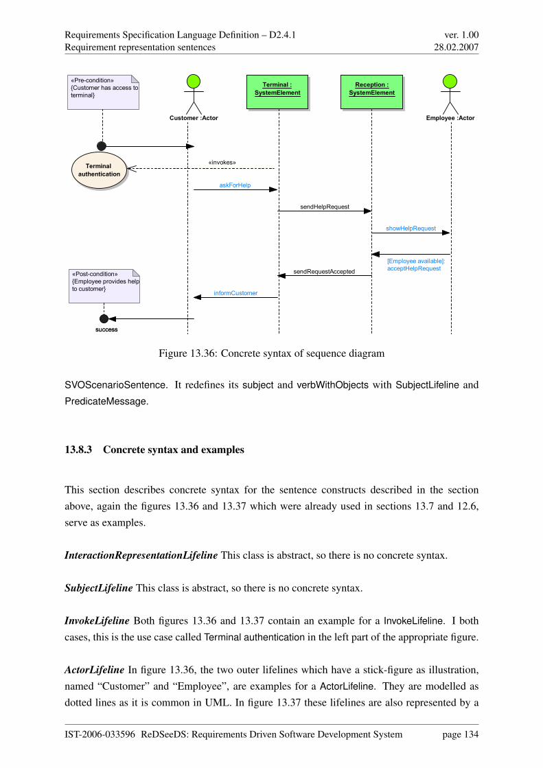
Requirements Specification Language Definition – D2.4.1Requirement representation sentences
ver. 1.0028.02.2007
Terminal :
SystemElement
Reception :
SystemElement
Customer :Actor Employee :Actor
successsuccess
«Pre-condition»
{Customer has access to
terminal}
Terminal
authentication
«Post-condition»
{Employee provides help
to customer}
«invokes»
askForHelp
sendHelpRequest
showHelpRequest
[Employee available]:
acceptHelpRequestsendRequestAccepted
informCustomer
Figure 13.36: Concrete syntax of sequence diagram
SVOScenarioSentence. It redefines its subject and verbWithObjects with SubjectLifeline andPredicateMessage.
13.8.3 Concrete syntax and examples
This section describes concrete syntax for the sentence constructs described in the sectionabove, again the figures 13.36 and 13.37 which were already used in sections 13.7 and 12.6,serve as examples.
InteractionRepresentationLifeline This class is abstract, so there is no concrete syntax.
SubjectLifeline This class is abstract, so there is no concrete syntax.
InvokeLifeline Both figures 13.36 and 13.37 contain an example for a InvokeLifeline. I bothcases, this is the use case called Terminal authentication in the left part of the appropriate figure.
ActorLifeline In figure 13.36, the two outer lifelines which have a stick-figure as illustration,named “Customer” and “Employee”, are examples for a ActorLifeline. They are modelled asdotted lines as it is common in UML. In figure 13.37 these lifelines are also represented by a
IST-2006-033596 ReDSeeDS: Requirements Driven Software Development System page 134
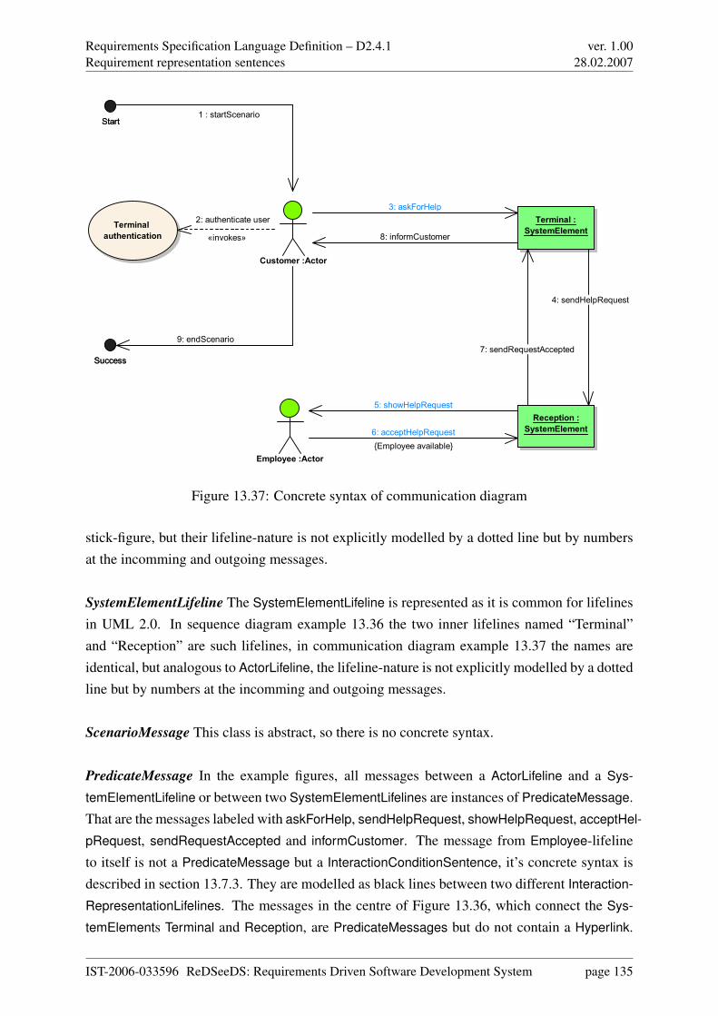
Requirements Specification Language Definition – D2.4.1Requirement representation sentences
ver. 1.0028.02.2007
Customer :Actor
Reception :
SystemElement
Terminal :
SystemElement
Employee :Actor
Terminal
authentication
StartStart
SuccessSuccess
1 : startScenario
6: acceptHelpRequest
{Employee available}
4: sendHelpRequest
8: informCustomer
5: showHelpRequest
7: sendRequestAccepted
9: endScenario
2: authenticate user
«invokes»
3: askForHelp
Figure 13.37: Concrete syntax of communication diagram
stick-figure, but their lifeline-nature is not explicitly modelled by a dotted line but by numbersat the incomming and outgoing messages.
SystemElementLifeline The SystemElementLifeline is represented as it is common for lifelinesin UML 2.0. In sequence diagram example 13.36 the two inner lifelines named “Terminal”and “Reception” are such lifelines, in communication diagram example 13.37 the names areidentical, but analogous to ActorLifeline, the lifeline-nature is not explicitly modelled by a dottedline but by numbers at the incomming and outgoing messages.
ScenarioMessage This class is abstract, so there is no concrete syntax.
PredicateMessage In the example figures, all messages between a ActorLifeline and a Sys-
temElementLifeline or between two SystemElementLifelines are instances of PredicateMessage.That are the messages labeled with askForHelp, sendHelpRequest, showHelpRequest, acceptHel-
pRequest, sendRequestAccepted and informCustomer. The message from Employee-lifelineto itself is not a PredicateMessage but a InteractionConditionSentence, it’s concrete syntax isdescribed in section 13.7.3. They are modelled as black lines between two different Interaction-
RepresentationLifelines. The messages in the centre of Figure 13.36, which connect the Sys-
temElements Terminal and Reception, are PredicateMessages but do not contain a Hyperlink.
IST-2006-033596 ReDSeeDS: Requirements Driven Software Development System page 135
Requirements Specification Language Definition – D2.4.1Requirement representation sentences
ver. 1.0028.02.2007
In this diagram, all messages between an Actor and a SystemElement contain a Hyperlink, as theblue font colour indicated. The whole blue part in the message name is the Hyperlink, it refers tothe appropriate Phrase in the vocabulary. The points where a PredicateMessage and a Interac-
tionRepresentationLifeline meet are ActorMessageEnds or SystemElementMessageEnds, theirnotation is explained at the description of the appropriate classes. The distribution of Hyperlinks
in this example is not representative, there is no general restriction for a message between anActor and a SystemElement to contain a Hyperlink neither a restriction for other messages tocontain no Hyperlinks.
ActorMessageEnd The connections between the ScenarioMessages and the ActorLifelines areActorMessageEnds. As it is common in UML sequence diagrams, the message whose end ismodelled just starts or ends at the appropriate lifeline. If the ActorMessageEnd has the roleof sendEvent, no additional graphical element is needed, if it has the role of receiveEvent theconnection to the lifeline is modelled as a black arrow, as it is common in UML. By analogy tothis, the messages in the communication diagram are represented as it is common in UML.
SystemElementMessageEnd The graphical representation of SystemComponentMessageEnd
is analogous to ActorMessageEnd, just it connects not to ActorLifelines but to SystemCompo-
nentLifelines.
InvokeMessageEnd InvokeMessageEnds model the connections between an InteractionInvoca-
tionSentence and a InvokeLifeline. Since their role may be only recieveEvent to InteractionIn-
vocationSentence, because a InvokeLifeline may only be invoked by another lifeline by maynot invoke another lifeline itself, InvokeMessageEnds are modelled as a black arrow, as it iscommon in UML for the recieveEvent message end.
InteractionSVOScenarioSentence The InteractionSVOScenarioSentences are not modelled ex-plicitly, but they are represented implicitly by the SubjectLifelines and PredicateMessages. Forinstance, the two lifelines called “Actor” and “Terminal” together with the PredicateMessage
“askForHelp” build up the InteractionSVOScenarioSentence “Actor asks for help at terminal”.
IST-2006-033596 ReDSeeDS: Requirements Driven Software Development System page 136
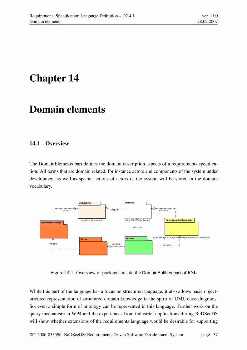
Requirements Specification Language Definition – D2.4.1Domain elements
ver. 1.0028.02.2007
Chapter 14
Domain elements
14.1 Overview
The DomainElements part defines the domain description aspects of a requirements specifica-tion. All terms that are domain related, for instance actors and components of the system underdevelopment as well as special actions of actors or the system will be stored in the domainvocabulary.
Terms Phrases
UML:Kernel
(from UMLMetaModel)TermsRelationships
Elements
(from RSLSyntax:Kernel) RepresentationSentences
(from RSLSyntax:RequirementRepresentationSentences)
«import»«import»«import»
«import»
«import» «import»«import»
Figure 14.1: Overview of packages inside the DomainEntities part of RSL
While this part of the language has a focus on structured language, it also allows basic object-oriented representation of structured domain knowledge in the spirit of UML class diagrams.So, even a simple form of ontology can be represented in this language. Further work on thequery mechanism in WP4 and the experiences from industrial applications during ReDSeeDSwill show whether extensions of the requirements language would be desirable for supporting
IST-2006-033596 ReDSeeDS: Requirements Driven Software Development System page 137
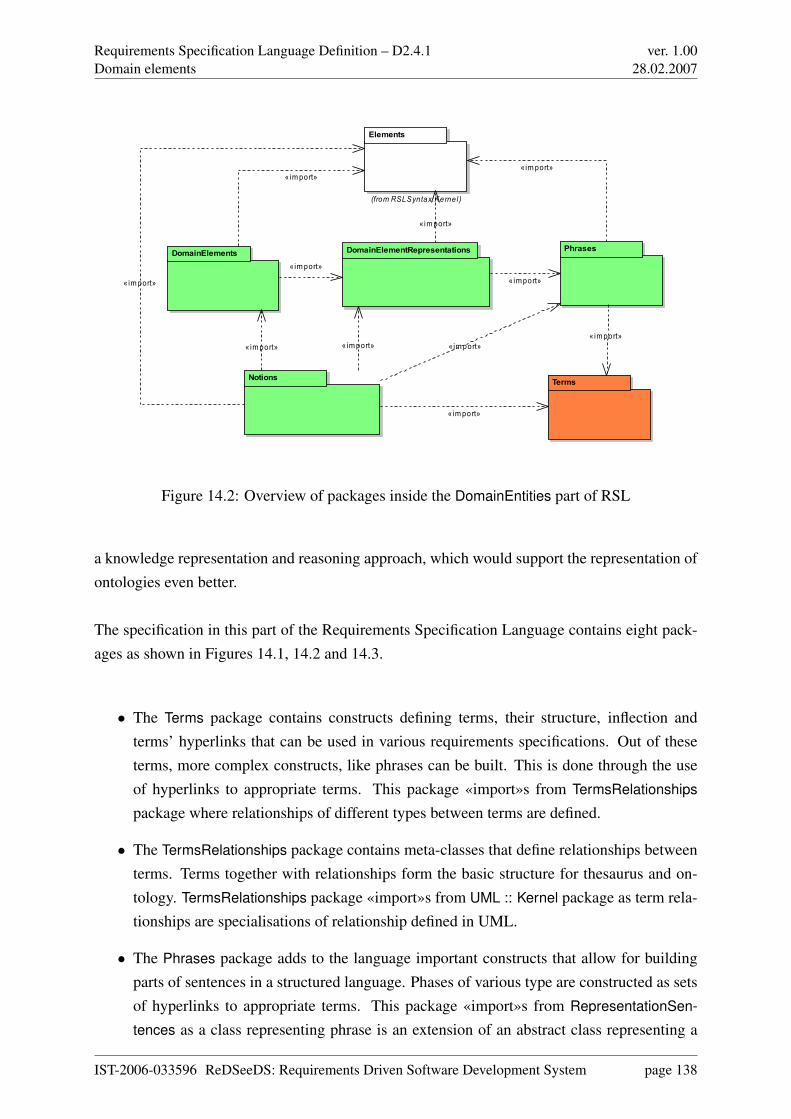
Requirements Specification Language Definition – D2.4.1Domain elements
ver. 1.0028.02.2007
DomainElements
Terms
PhrasesDomainElementRepresentations
Notions
Elements
(from RSLSyntax:Kernel)
«import»
«import»
«import»
«import» «import»
«import»
«import»
«import»
«import»
«import»
«import»
Figure 14.2: Overview of packages inside the DomainEntities part of RSL
a knowledge representation and reasoning approach, which would support the representation ofontologies even better.
The specification in this part of the Requirements Specification Language contains eight pack-ages as shown in Figures 14.1, 14.2 and 14.3.
• The Terms package contains constructs defining terms, their structure, inflection andterms’ hyperlinks that can be used in various requirements specifications. Out of theseterms, more complex constructs, like phrases can be built. This is done through the useof hyperlinks to appropriate terms. This package «import»s from TermsRelationships
package where relationships of different types between terms are defined.
• The TermsRelationships package contains meta-classes that define relationships betweenterms. Terms together with relationships form the basic structure for thesaurus and on-tology. TermsRelationships package «import»s from UML :: Kernel package as term rela-tionships are specialisations of relationship defined in UML.
• The Phrases package adds to the language important constructs that allow for buildingparts of sentences in a structured language. Phases of various type are constructed as setsof hyperlinks to appropriate terms. This package «import»s from RepresentationSen-
tences as a class representing phrase is an extension of an abstract class representing a
IST-2006-033596 ReDSeeDS: Requirements Driven Software Development System page 138
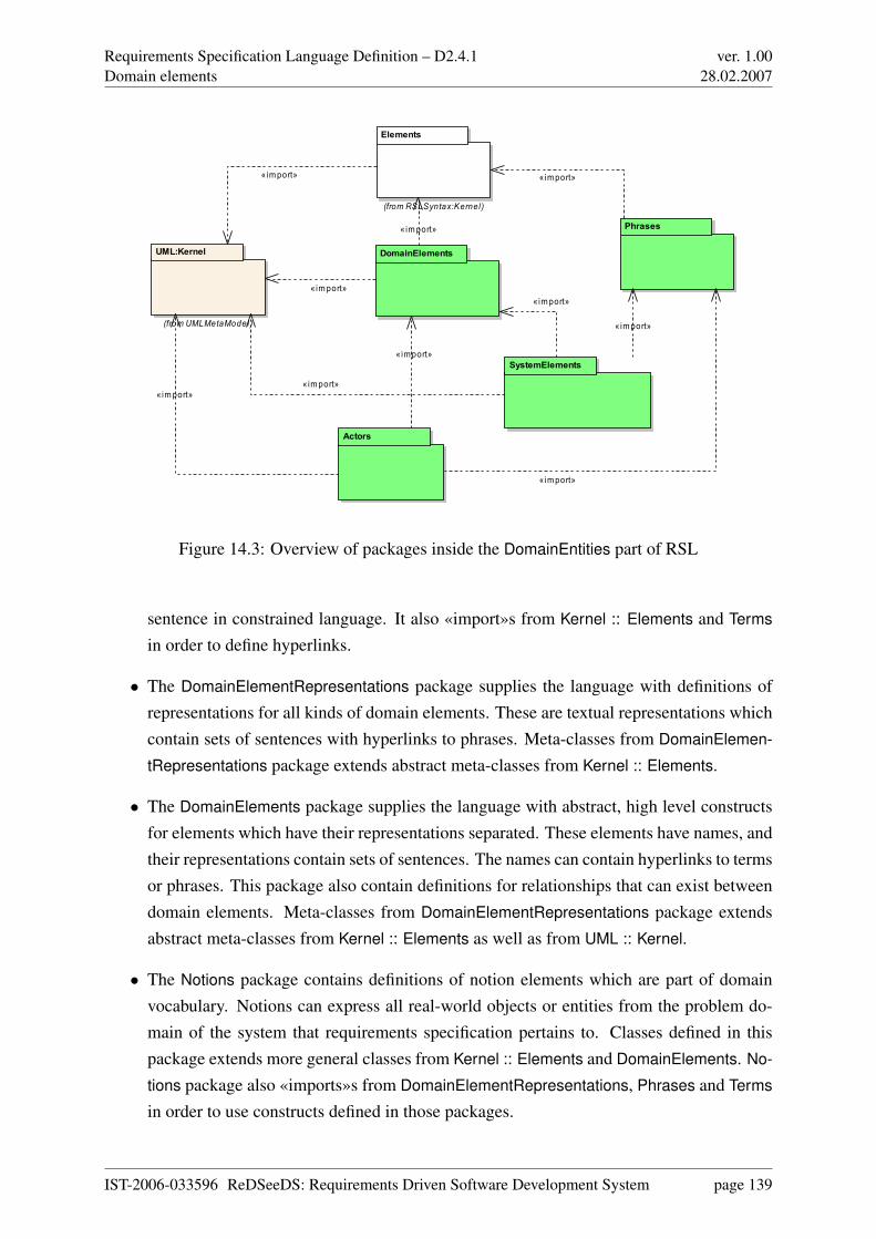
Requirements Specification Language Definition – D2.4.1Domain elements
ver. 1.0028.02.2007
SystemElements
DomainElements
Phrases
UML:Kernel
(from UMLMetaModel )
Actors
Elements
(from RSLSyntax:Kernel)
«import»
«import»
«import»
«import»
«import»
«import»
«import» «import»
«import»
«import»
Figure 14.3: Overview of packages inside the DomainEntities part of RSL
sentence in constrained language. It also «import»s from Kernel :: Elements and Terms
in order to define hyperlinks.
• The DomainElementRepresentations package supplies the language with definitions ofrepresentations for all kinds of domain elements. These are textual representations whichcontain sets of sentences with hyperlinks to phrases. Meta-classes from DomainElemen-
tRepresentations package extends abstract meta-classes from Kernel :: Elements.
• The DomainElements package supplies the language with abstract, high level constructsfor elements which have their representations separated. These elements have names, andtheir representations contain sets of sentences. The names can contain hyperlinks to termsor phrases. This package also contain definitions for relationships that can exist betweendomain elements. Meta-classes from DomainElementRepresentations package extendsabstract meta-classes from Kernel :: Elements as well as from UML :: Kernel.
• The Notions package contains definitions of notion elements which are part of domainvocabulary. Notions can express all real-world objects or entities from the problem do-main of the system that requirements specification pertains to. Classes defined in thispackage extends more general classes from Kernel :: Elements and DomainElements. No-
tions package also «imports»s from DomainElementRepresentations, Phrases and Terms
in order to use constructs defined in those packages.
IST-2006-033596 ReDSeeDS: Requirements Driven Software Development System page 139
Requirements Specification Language Definition – D2.4.1Domain elements
ver. 1.0028.02.2007
• The Actors package allows for defining actors as part of the domain vocabulary. Therecan be shown relationships between actors. Actors are representable, and can have de-scriptions in hyperlinked text. Elements in this package extends general elements fromDomainElements and UML :: Kernel. It also «import»s constructs from Phrases.
• The SytemElements package adds to the vocabulary the possibility to express the systemand its general components. This does not allow for designing the system but allows forshowing those elements of the system that might be used inside requirements specifica-tions. Elements in this package extends general elements from DomainElements and UML
:: Kernel. It also «import»s constructs from Phrases.
Generally, the vocabularies defined through our language consist of RepresentableElements
which have names and HyperlinkedSentences as descriptions. Since these HyperlinkedSen-
tences may contain Hyperlinks, RerpesentableElements resp. their descriptions that are relatedto each other are logically connected.
RepresentableElements can be actors, system components, special actions or entities that aredomain-related, but not part of the system under development. Hence, the class Representable-
Element is a base class for some more special classes such as Actor, SystemComponent, and Do-
mainElement. Everyone of these classes derived from RepresentableElement may have specialassociations to other RepresentableElements, for instance the DomainElement called wristband
in the fitness-club is associated with the Actor customer as every customer wears a wristband.These associations are modelled with the class DomainElementAssociation and derived ones.
14.2 Domain elements
14.2.1 Overview
This package describes the general structure of domain elements as part of RequirementsSpec-
ifications :: RequirementsSpecification. It consists of DomainSpecification class that defines thetop level element holding a whole collection of DomainElements for a specific system groupedin DomainElementsPackages.DomainSpecification and DomainElementsPackages can be presented in Package Diagrams thathave their syntax derived from UML Package Diagrams. DomainElements are presented in No-
tions :: Notion Diagrams, SystemElements :: SystemElement Diagrams or in Actors :: Actor
Diagrams, while DomainElement is abstract and superclass for these classes. DomainElements
IST-2006-033596 ReDSeeDS: Requirements Driven Software Development System page 140
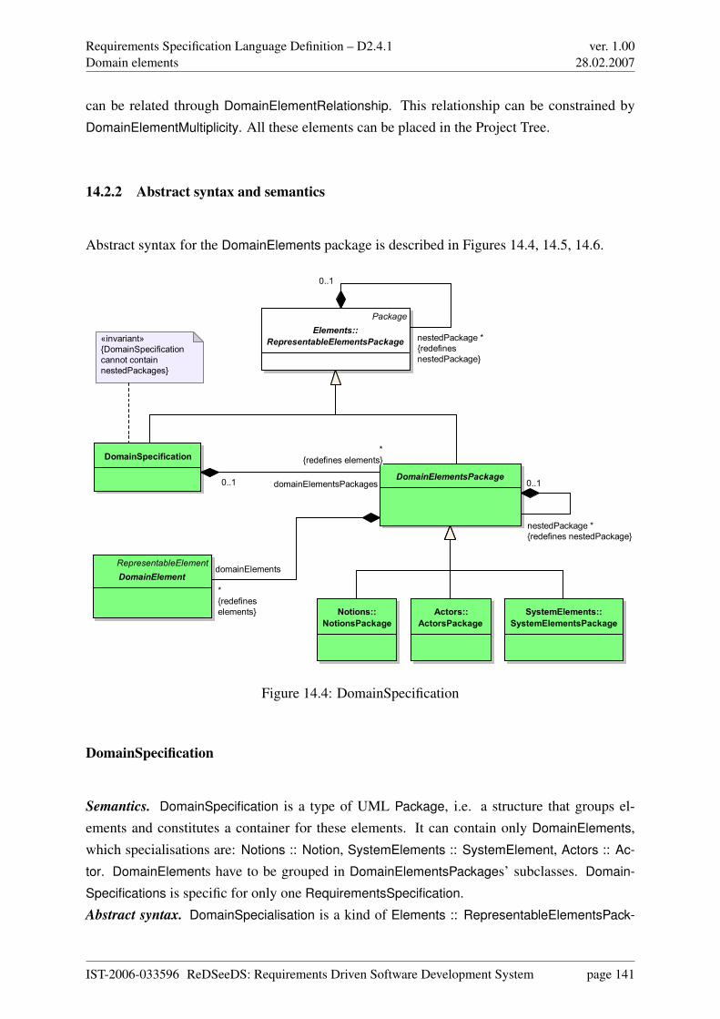
Requirements Specification Language Definition – D2.4.1Domain elements
ver. 1.0028.02.2007
can be related through DomainElementRelationship. This relationship can be constrained byDomainElementMultiplicity. All these elements can be placed in the Project Tree.
14.2.2 Abstract syntax and semantics
Abstract syntax for the DomainElements package is described in Figures 14.4, 14.5, 14.6.
DomainSpecification
RepresentableElement
DomainElement
DomainElementsPackage
Package
Elements::
RepresentableElementsPackage
Notions::
NotionsPackage
Actors::
ActorsPackage
SystemElements::
SystemElementsPackage
«invariant»
{DomainSpecification
cannot contain
nestedPackages}
domainElements
*
{redefines
elements}
domainElementsPackages
*
{redefines elements}
0..1
nestedPackage *
{redefines nestedPackage}
0..1
nestedPackage *
{redefines
nestedPackage}
0..1
Figure 14.4: DomainSpecification
DomainSpecification
Semantics. DomainSpecification is a type of UML Package, i.e. a structure that groups el-ements and constitutes a container for these elements. It can contain only DomainElements,which specialisations are: Notions :: Notion, SystemElements :: SystemElement, Actors :: Ac-
tor. DomainElements have to be grouped in DomainElementsPackages’ subclasses. Domain-
Specifications is specific for only one RequirementsSpecification.Abstract syntax. DomainSpecialisation is a kind of Elements :: RepresentableElementsPack-
IST-2006-033596 ReDSeeDS: Requirements Driven Software Development System page 141
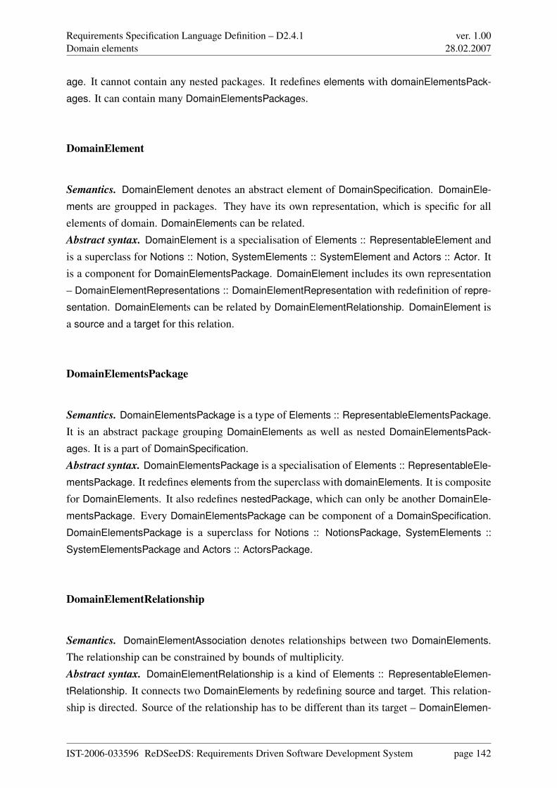
Requirements Specification Language Definition – D2.4.1Domain elements
ver. 1.0028.02.2007
age. It cannot contain any nested packages. It redefines elements with domainElementsPack-
ages. It can contain many DomainElementsPackages.
DomainElement
Semantics. DomainElement denotes an abstract element of DomainSpecification. DomainEle-
ments are groupped in packages. They have its own representation, which is specific for allelements of domain. DomainElements can be related.Abstract syntax. DomainElement is a specialisation of Elements :: RepresentableElement andis a superclass for Notions :: Notion, SystemElements :: SystemElement and Actors :: Actor. Itis a component for DomainElementsPackage. DomainElement includes its own representation– DomainElementRepresentations :: DomainElementRepresentation with redefinition of repre-
sentation. DomainElements can be related by DomainElementRelationship. DomainElement isa source and a target for this relation.
DomainElementsPackage
Semantics. DomainElementsPackage is a type of Elements :: RepresentableElementsPackage.It is an abstract package grouping DomainElements as well as nested DomainElementsPack-
ages. It is a part of DomainSpecification.Abstract syntax. DomainElementsPackage is a specialisation of Elements :: RepresentableEle-
mentsPackage. It redefines elements from the superclass with domainElements. It is compositefor DomainElements. It also redefines nestedPackage, which can only be another DomainEle-
mentsPackage. Every DomainElementsPackage can be component of a DomainSpecification.DomainElementsPackage is a superclass for Notions :: NotionsPackage, SystemElements ::
SystemElementsPackage and Actors :: ActorsPackage.
DomainElementRelationship
Semantics. DomainElementAssociation denotes relationships between two DomainElements.The relationship can be constrained by bounds of multiplicity.Abstract syntax. DomainElementRelationship is a kind of Elements :: RepresentableElemen-
tRelationship. It connects two DomainElements by redefining source and target. This relation-ship is directed. Source of the relationship has to be different than its target – DomainElemen-
IST-2006-033596 ReDSeeDS: Requirements Driven Software Development System page 142
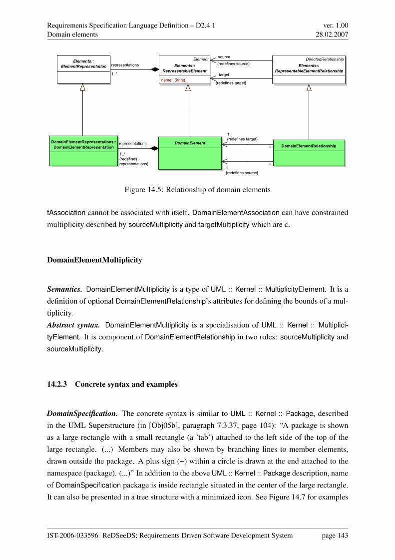
Requirements Specification Language Definition – D2.4.1Domain elements
ver. 1.0028.02.2007
Element
Elements::
RepresentableElement
name: String
DomainElementRelationshipDomainElementRepresentations::
DomainElementRepresentationDomainElement
Elements::
ElementRepresentation
DirectedRelationship
Elements::
RepresentableElementRelationship
*
1
{redefines target}
*1
{redefines source}
representations
1..*
{redefines
representations}
representations
1..* target
{redefines target}
source
{redefines source}
Figure 14.5: Relationship of domain elements
tAssociation cannot be associated with itself. DomainElementAssociation can have constrainedmultiplicity described by sourceMultiplicity and targetMultiplicity which are c.
DomainElementMultiplicity
Semantics. DomainElementMultiplicity is a type of UML :: Kernel :: MultiplicityElement. It is adefinition of optional DomainElementRelationship’s attributes for defining the bounds of a mul-tiplicity.Abstract syntax. DomainElementMultiplicity is a specialisation of UML :: Kernel :: Multiplici-
tyElement. It is component of DomainElementRelationship in two roles: sourceMultiplicity andsourceMultiplicity.
14.2.3 Concrete syntax and examples
DomainSpecification. The concrete syntax is similar to UML :: Kernel :: Package, describedin the UML Superstructure (in [Obj05b], paragraph 7.3.37, page 104): “A package is shownas a large rectangle with a small rectangle (a ’tab’) attached to the left side of the top of thelarge rectangle. (...) Members may also be shown by branching lines to member elements,drawn outside the package. A plus sign (+) within a circle is drawn at the end attached to thenamespace (package). (...)” In addition to the above UML :: Kernel :: Package description, nameof DomainSpecification package is inside rectangle situated in the center of the large rectangle.It can also be presented in a tree structure with a minimized icon. See Figure 14.7 for examples
IST-2006-033596 ReDSeeDS: Requirements Driven Software Development System page 143
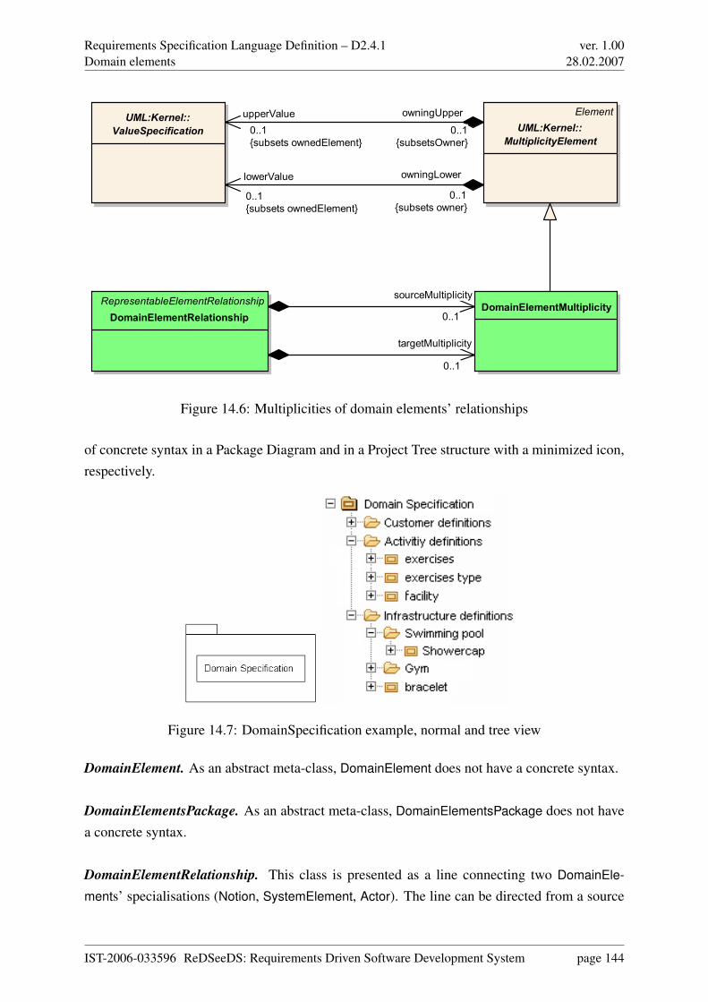
Requirements Specification Language Definition – D2.4.1Domain elements
ver. 1.0028.02.2007
RepresentableElementRelationship
DomainElementRelationshipDomainElementMultiplicity
Element
UML:Kernel::
MultiplicityElement
UML:Kernel::
ValueSpecification
sourceMultiplicity
0..1
targetMultiplicity
0..1
owningLower
0..1
{subsets owner}
lowerValue
0..1
{subsets ownedElement}
owningUpper
0..1
{subsetsOwner}
upperValue
0..1
{subsets ownedElement}
Figure 14.6: Multiplicities of domain elements’ relationships
of concrete syntax in a Package Diagram and in a Project Tree structure with a minimized icon,respectively.
Figure 14.7: DomainSpecification example, normal and tree view
DomainElement. As an abstract meta-class, DomainElement does not have a concrete syntax.
DomainElementsPackage. As an abstract meta-class, DomainElementsPackage does not havea concrete syntax.
DomainElementRelationship. This class is presented as a line connecting two DomainEle-
ments’ specialisations (Notion, SystemElement, Actor). The line can be directed from a source
IST-2006-033596 ReDSeeDS: Requirements Driven Software Development System page 144
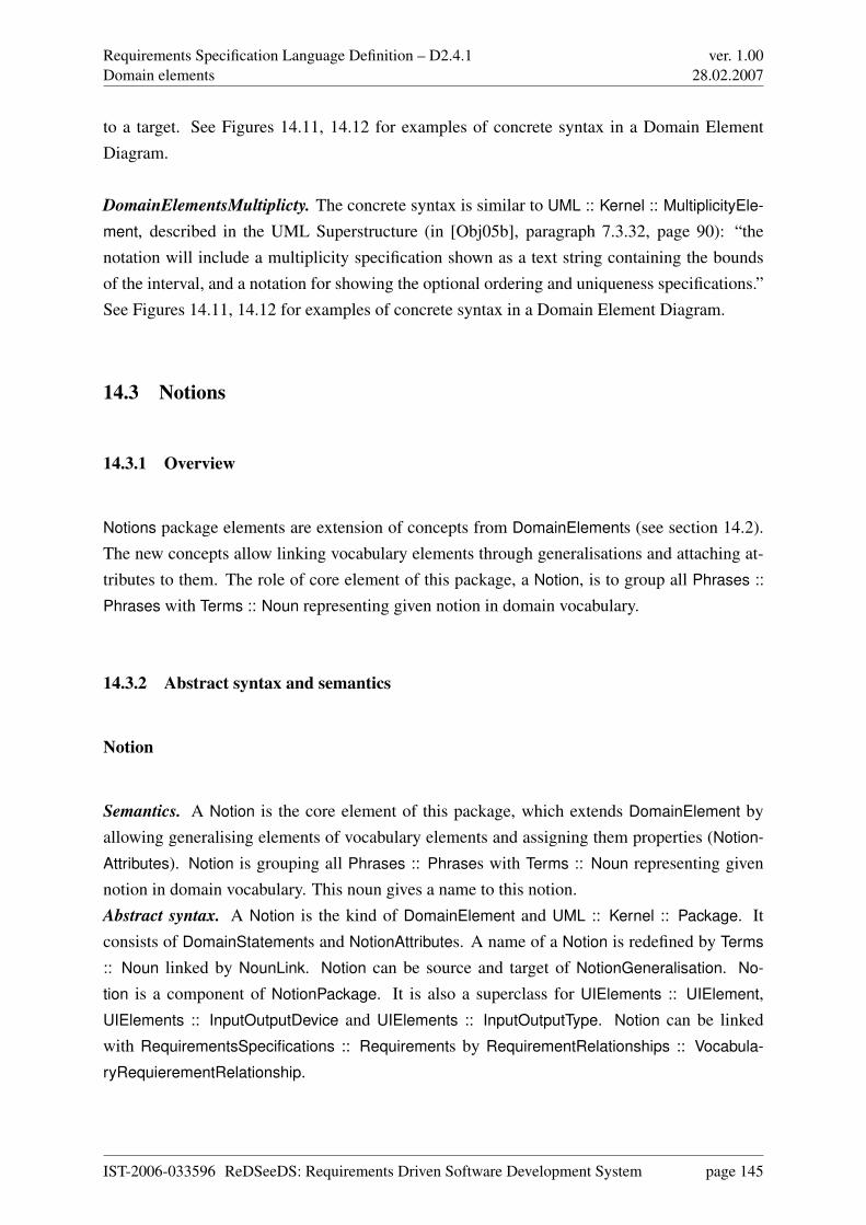
Requirements Specification Language Definition – D2.4.1Domain elements
ver. 1.0028.02.2007
to a target. See Figures 14.11, 14.12 for examples of concrete syntax in a Domain ElementDiagram.
DomainElementsMultiplicty. The concrete syntax is similar to UML :: Kernel :: MultiplicityEle-
ment, described in the UML Superstructure (in [Obj05b], paragraph 7.3.32, page 90): “thenotation will include a multiplicity specification shown as a text string containing the boundsof the interval, and a notation for showing the optional ordering and uniqueness specifications.”See Figures 14.11, 14.12 for examples of concrete syntax in a Domain Element Diagram.
14.3 Notions
14.3.1 Overview
Notions package elements are extension of concepts from DomainElements (see section 14.2).The new concepts allow linking vocabulary elements through generalisations and attaching at-tributes to them. The role of core element of this package, a Notion, is to group all Phrases ::
Phrases with Terms :: Noun representing given notion in domain vocabulary.
14.3.2 Abstract syntax and semantics
Notion
Semantics. A Notion is the core element of this package, which extends DomainElement byallowing generalising elements of vocabulary elements and assigning them properties (Notion-
Attributes). Notion is grouping all Phrases :: Phrases with Terms :: Noun representing givennotion in domain vocabulary. This noun gives a name to this notion.Abstract syntax. A Notion is the kind of DomainElement and UML :: Kernel :: Package. Itconsists of DomainStatements and NotionAttributes. A name of a Notion is redefined by Terms
:: Noun linked by NounLink. Notion can be source and target of NotionGeneralisation. No-
tion is a component of NotionPackage. It is also a superclass for UIElements :: UIElement,UIElements :: InputOutputDevice and UIElements :: InputOutputType. Notion can be linkedwith RequirementsSpecifications :: Requirements by RequirementRelationships :: Vocabula-
ryRequierementRelationship.
IST-2006-033596 ReDSeeDS: Requirements Driven Software Development System page 145
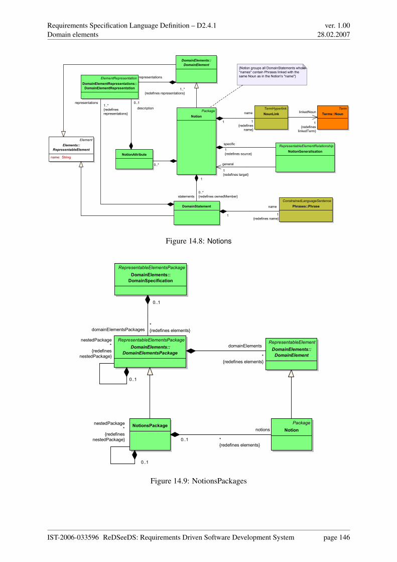
Requirements Specification Language Definition – D2.4.1Domain elements
ver. 1.0028.02.2007
Package
Notion
TermHyperlink
NounLink
DomainStatement
Term
Terms::Noun
Element
Elements::
RepresentableElement
name: String
ConstrainedLanguageSentence
Phrases::Phrase
{Notion groups all DomainStatements whose
"names" contain Phrases linked with the
same Noun as in the Notion's "name"}ElementRepresentation
DomainElementRepresentations::
DomainElementRepresentation
DomainElements::
DomainElement
RepresentableElementRelationship
NotionGeneralisationNotionAttribute
name
1
{redefines
name}
1
linkedNoun
1
{redefines
linkedTerm}
statements
0..*
{redefines ownedMember}
1
name
1
{redefines name}1
representations1..*
{redefines
representations}
representations
1..*
{redefines representations}
description
0..1
general
1
{redefines target}
specific
1
{redefines source}
0..*
Figure 14.8: Notions
Package
Notion
RepresentableElementsPackage
DomainElements::
DomainElementsPackage
NotionsPackage
RepresentableElement
DomainElements::
DomainElement
RepresentableElementsPackage
DomainElements::
DomainSpecification
notions
*
{redefines elements}
0..1
nestedPackage
*
{redefines
nestedPackage}
0..1
domainElementsPackages*
{redefines elements}
0..1
nestedPackage
*
{redefines
nestedPackage}
0..1
domainElements
*
{redefines elements}
Figure 14.9: NotionsPackages
IST-2006-033596 ReDSeeDS: Requirements Driven Software Development System page 146
Requirements Specification Language Definition – D2.4.1Domain elements
ver. 1.0028.02.2007
DomainStatement
Semantics. DomainStatement is a wiki-like description of an element of the domain of thesystem to be developed with its context - noun with modifiers, verbs and other nouns. Domain-
Statements are grouped in Notion in a role of statements, which are forming a container for allPhrases :: Phrases related to Notion that this statements are component of.Abstract syntax. DomainStatement is kind of Kernel :: RepresentableElement. The inheritedname attribute is redefined by Phrases :: Phrase. It consists of DomainElementRepresentations.DomainStatement is associated with Phrases :: PhraseHyperlink.
NotionAttribute
Semantics. A NotionAttribute is used for attaching Notion specific properties to domain vocab-ulary notions. Those properties have descriptions represented similarly to DomainElements.Abstract syntax. A NotionAttribute is a component of a Notion and consists of DomainElement-
Representation as its description.
NotionGeneralisation
Semantics. A NotionGeneralisation allows parent-child relationships between two Notions: amore general Notion and more specific Notion.Abstract syntax. A NotionGeneralisation is a kind of RepresentableElementRelationship. Itlinks two Notions - specific and general.
NotionPackage
Semantics. A NotionPackage is used for grouping Notions in packages, which can be includedin requirements specification.Abstract syntax. NotionPackage is a kind of DomainElements :: DomainElementsPackage. Itcan have other NotionPackages included in it. NotionPackage consists of Notions.
IST-2006-033596 ReDSeeDS: Requirements Driven Software Development System page 147
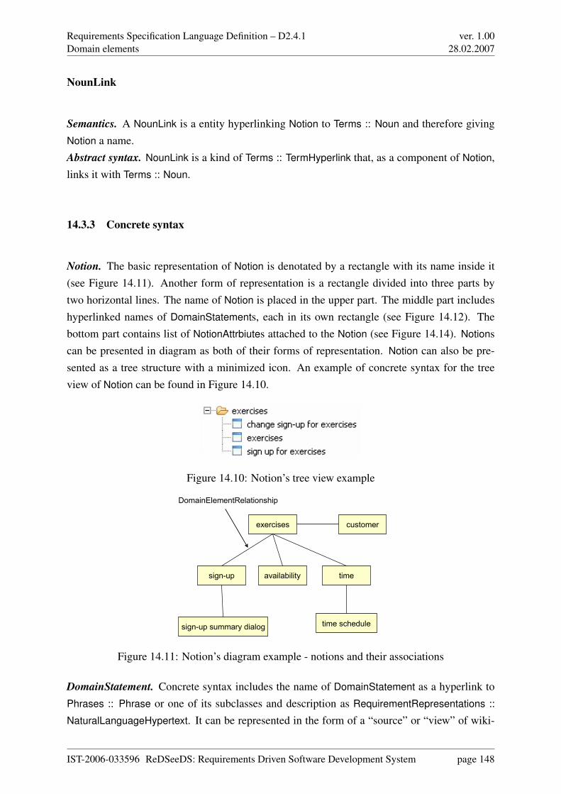
Requirements Specification Language Definition – D2.4.1Domain elements
ver. 1.0028.02.2007
NounLink
Semantics. A NounLink is a entity hyperlinking Notion to Terms :: Noun and therefore givingNotion a name.Abstract syntax. NounLink is a kind of Terms :: TermHyperlink that, as a component of Notion,links it with Terms :: Noun.
14.3.3 Concrete syntax
Notion. The basic representation of Notion is denotated by a rectangle with its name inside it(see Figure 14.11). Another form of representation is a rectangle divided into three parts bytwo horizontal lines. The name of Notion is placed in the upper part. The middle part includeshyperlinked names of DomainStatements, each in its own rectangle (see Figure 14.12). Thebottom part contains list of NotionAttrbiutes attached to the Notion (see Figure 14.14). Notionscan be presented in diagram as both of their forms of representation. Notion can also be pre-sented as a tree structure with a minimized icon. An example of concrete syntax for the treeview of Notion can be found in Figure 14.10.
Figure 14.10: Notion’s tree view example
customer
time schedule
exercises
sign-up
sign-up summary dialog
timeavailability
DomainElementRelationship
Figure 14.11: Notion’s diagram example - notions and their associations
DomainStatement. Concrete syntax includes the name of DomainStatement as a hyperlink toPhrases :: Phrase or one of its subclasses and description as RequirementRepresentations ::
NaturalLanguageHypertext. It can be represented in the form of a “source” or “view” of wiki-
IST-2006-033596 ReDSeeDS: Requirements Driven Software Development System page 148
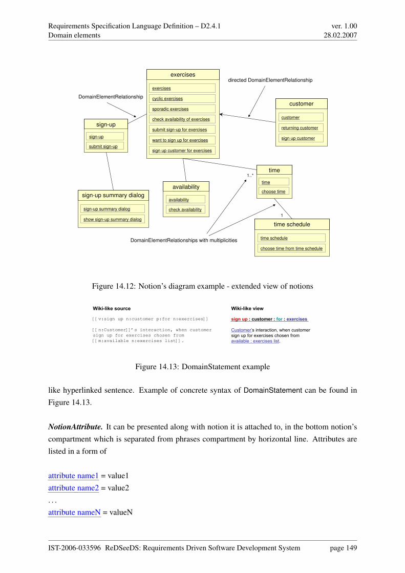
Requirements Specification Language Definition – D2.4.1Domain elements
ver. 1.0028.02.2007
sign-up summary dialog
sign-up summary dialog
show sign-up summary dialog
exercises
cyclic exercises
sporadic exercises
check availability of exercises
submit sign-up for exercises
want to sign up for exercises
sign up customer for exercises
exercises
customer
customer
returning customer
sign up customer
time schedule
time schedule
choose time from time schedule
time
time
choose timeavailability
availability
check availability
sign-up
sign-up
submit sign-up
DomainElementRelationship
directed DomainElementRelationship
1..*
1
DomainElementRelationships with multiplicities
Figure 14.12: Notion’s diagram example - extended view of notions
sign up : customer : for : exercises
Customer’s interaction, when customer sign up for exercises chosen from available : exercises list.
Wiki-like view
[[v:sign up n:customer p:for n:exercises]]
[[n:Customer]]’s interaction, when customer sign up for exercises chosen from [[m:available n:exercises list]].
Wiki-like source
Figure 14.13: DomainStatement example
like hyperlinked sentence. Example of concrete syntax of DomainStatement can be found inFigure 14.13.
NotionAttribute. It can be presented along with notion it is attached to, in the bottom notion’scompartment which is separated from phrases compartment by horizontal line. Attributes arelisted in a form of
attribute name1 = value1attribute name2 = value2. . .attribute nameN = valueN
IST-2006-033596 ReDSeeDS: Requirements Driven Software Development System page 149
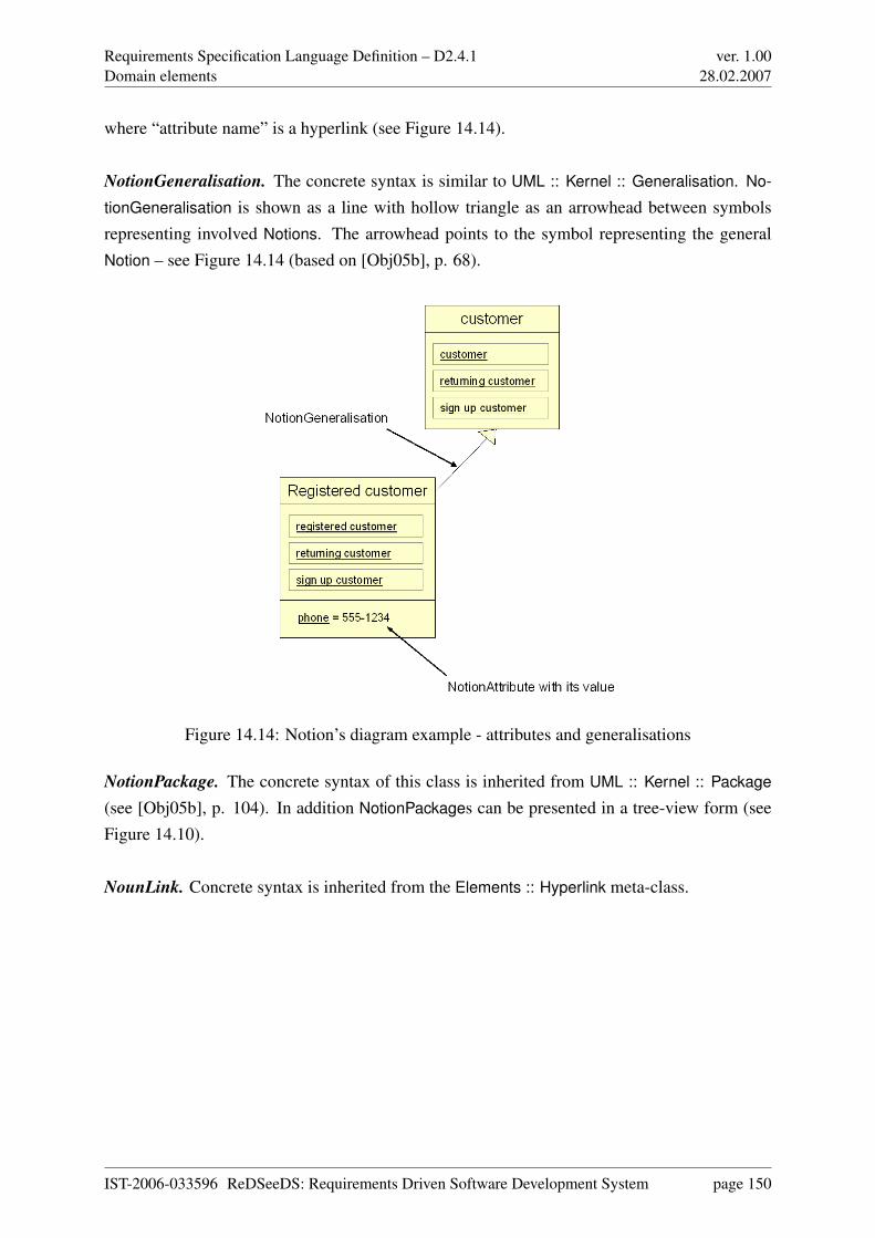
Requirements Specification Language Definition – D2.4.1Domain elements
ver. 1.0028.02.2007
where “attribute name” is a hyperlink (see Figure 14.14).
NotionGeneralisation. The concrete syntax is similar to UML :: Kernel :: Generalisation. No-
tionGeneralisation is shown as a line with hollow triangle as an arrowhead between symbolsrepresenting involved Notions. The arrowhead points to the symbol representing the generalNotion – see Figure 14.14 (based on [Obj05b], p. 68).
Figure 14.14: Notion’s diagram example - attributes and generalisations
NotionPackage. The concrete syntax of this class is inherited from UML :: Kernel :: Package
(see [Obj05b], p. 104). In addition NotionPackages can be presented in a tree-view form (seeFigure 14.10).
NounLink. Concrete syntax is inherited from the Elements :: Hyperlink meta-class.
IST-2006-033596 ReDSeeDS: Requirements Driven Software Development System page 150
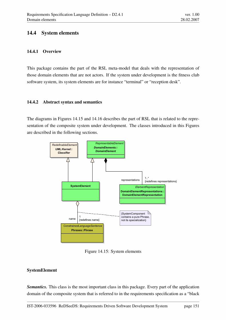
Requirements Specification Language Definition – D2.4.1Domain elements
ver. 1.0028.02.2007
14.4 System elements
14.4.1 Overview
This package contains the part of the RSL meta-model that deals with the representation ofthose domain elements that are not actors. If the system under development is the fitness clubsoftware system, its system elements are for instance “terminal” or “reception desk”.
14.4.2 Abstract syntax and semantics
The diagrams in Figures 14.15 and 14.16 describes the part of RSL that is related to the repre-sentation of the composite system under development. The classes introduced in this Figuresare described in the following sections.
SystemElement
RedefinableElement
UML:Kernel::
Classifier
ConstrainedLanguageSentence
Phrases::Phrase
ElementRepresentation
DomainElementRepresentations::
DomainElementRepresentation
RepresentableElement
DomainElements::
DomainElement
{SystemComponent
contains a pure Phrase,
not its specialization}name
1
{redefines name}
representations1..*
{redefines representations}
Figure 14.15: System elements
SystemElement
Semantics. This class is the most important class in this package. Every part of the applicationdomain of the composite system that is referred to in the requirements specification as a “black
IST-2006-033596 ReDSeeDS: Requirements Driven Software Development System page 151
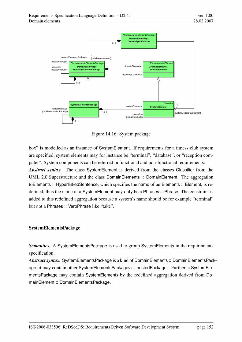
Requirements Specification Language Definition – D2.4.1Domain elements
ver. 1.0028.02.2007
Classifier
SystemElement
RepresentableElement
DomainElements::
DomainElement
RepresentableElementsPackage
DomainElements::
DomainElementsPackage
SystemElementsPackage
RepresentableElementsPackage
DomainElements::
DomainSpecification
systemElements
*
{redefines
domainElements}
0..1
domainElements
*
{redefines elements}
nestedPackage
*
{redefines
nestedPackage}
0..1
domainElementsPackages*
{redefines elements}
0..1
nestedPackage *
{redefines nestedPackage}
0..1
systemUnderDevelopment
1
Figure 14.16: System package
box” is modelled as an instance of SystemElement. If requirements for a fitness club systemare specified, system elements may for instance be “terminal”, “database”, or “reception com-puter”. System components can be referred in functional and non-functional requirements.Abstract syntax. The class SystemElement is derived from the classes Classifier from theUML 2.0 Superstructure and the class DomainElements :: DomainElement. The aggregationtoElements :: HyperlinkedSentence, which specifies the name of an Elements :: Element, is re-defined, thus the name of a SystemElement may only be a Phrases :: Phrase. The constraint isadded to this redefined aggregation because a system’s name should be for example “terminal”but not a Phrases :: VerbPhrase like “take”.
SystemElementsPackage
Semantics. A SystemElementsPackage is used to group SystemElements in the requirementsspecification.Abstract syntax. SystemElementsPackage is a kind of DomainElements :: DomainElementsPack-
age, it may contain other SystemElementsPackages as nestedPackages. Further, a SystemEle-
mentsPackage may contain SystemElements by the redefined aggregation derived from Do-
mainElement :: DomainElementsPackage.
IST-2006-033596 ReDSeeDS: Requirements Driven Software Development System page 152
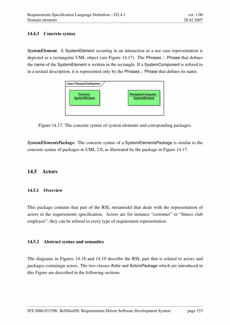
Requirements Specification Language Definition – D2.4.1Domain elements
ver. 1.0028.02.2007
14.4.3 Concrete syntax
SystemElement. A SystemElement occuring in an interaction or a use case representation isdepicted as a rectangular UML object (see Figure 14.17). The Phrases :: Phrase that definesthe name of the SystemElement is written in the rectangle. If a SystemComponent is refered toin a textual description, it is represented only by the Phrases :: Phrase that defines its name.
class FitnessClubSystem
Terminal :
SystemElement
ReceptionComputer :
SystemElement
Figure 14.17: The concrete syntax of system elements and coresponding packages.
SystemElementsPackage. The concrete syntax of a SystemElementsPackage is similar to theconcrete syntax of packages in UML 2.0, as illustrated by the package in Figure 14.17.
14.5 Actors
14.5.1 Overview
This package contains that part of the RSL metamodel that deals with the representation ofactors in the requirements specification. Actors are for instance “customer” or “fitness clubemployee”, they can be refered in every type of requirement representation.
14.5.2 Abstract syntax and semantics
The diagrams in Figures 14.18 and 14.19 describe the RSL part that is related to actors andpackages containign actors. The two classes Actor and ActorsPackage which are introduced inthis Figure are described in the following sections.
IST-2006-033596 ReDSeeDS: Requirements Driven Software Development System page 153
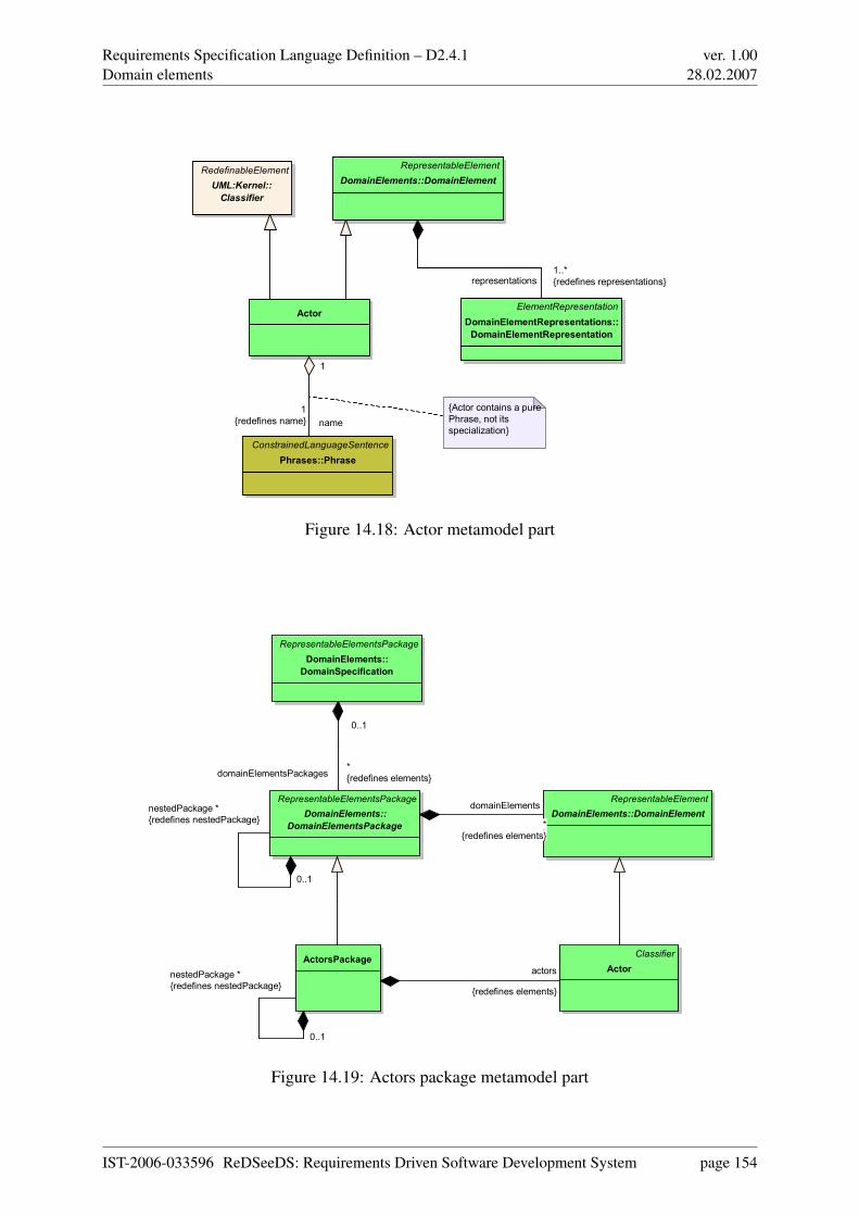
Requirements Specification Language Definition – D2.4.1Domain elements
ver. 1.0028.02.2007
Actor
ConstrainedLanguageSentence
Phrases::Phrase
{Actor contains a pure
Phrase, not its
specialization}
RedefinableElement
UML:Kernel::
Classifier
ElementRepresentation
DomainElementRepresentations::
DomainElementRepresentation
RepresentableElement
DomainElements::DomainElement
name
1
{redefines name}
1
representations1..*
{redefines representations}
Figure 14.18: Actor metamodel part
Classifier
Actor
RepresentableElement
DomainElements::DomainElement
RepresentableElementsPackage
DomainElements::
DomainElementsPackage
ActorsPackage
RepresentableElementsPackage
DomainElements::
DomainSpecification
actors
{redefines elements}
domainElements
*
{redefines elements}
nestedPackage *
{redefines nestedPackage}
0..1
domainElementsPackages*
{redefines elements}
0..1
nestedPackage *
{redefines nestedPackage}
0..1
Figure 14.19: Actors package metamodel part
IST-2006-033596 ReDSeeDS: Requirements Driven Software Development System page 154
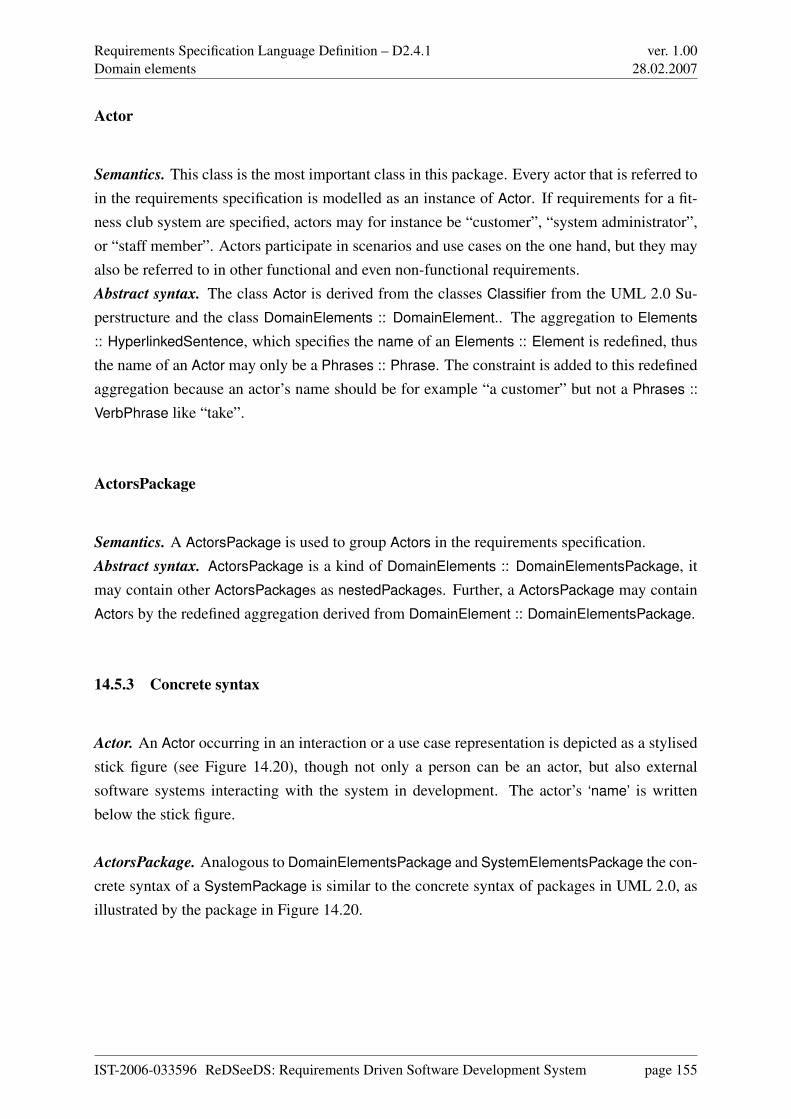
Requirements Specification Language Definition – D2.4.1Domain elements
ver. 1.0028.02.2007
Actor
Semantics. This class is the most important class in this package. Every actor that is referred toin the requirements specification is modelled as an instance of Actor. If requirements for a fit-ness club system are specified, actors may for instance be “customer”, “system administrator”,or “staff member”. Actors participate in scenarios and use cases on the one hand, but they mayalso be referred to in other functional and even non-functional requirements.Abstract syntax. The class Actor is derived from the classes Classifier from the UML 2.0 Su-perstructure and the class DomainElements :: DomainElement.. The aggregation to Elements
:: HyperlinkedSentence, which specifies the name of an Elements :: Element is redefined, thusthe name of an Actor may only be a Phrases :: Phrase. The constraint is added to this redefinedaggregation because an actor’s name should be for example “a customer” but not a Phrases ::
VerbPhrase like “take”.
ActorsPackage
Semantics. A ActorsPackage is used to group Actors in the requirements specification.Abstract syntax. ActorsPackage is a kind of DomainElements :: DomainElementsPackage, itmay contain other ActorsPackages as nestedPackages. Further, a ActorsPackage may containActors by the redefined aggregation derived from DomainElement :: DomainElementsPackage.
14.5.3 Concrete syntax
Actor. An Actor occurring in an interaction or a use case representation is depicted as a stylisedstick figure (see Figure 14.20), though not only a person can be an actor, but also externalsoftware systems interacting with the system in development. The actor’s ‘name’ is writtenbelow the stick figure.
ActorsPackage. Analogous to DomainElementsPackage and SystemElementsPackage the con-crete syntax of a SystemPackage is similar to the concrete syntax of packages in UML 2.0, asillustrated by the package in Figure 14.20.
IST-2006-033596 ReDSeeDS: Requirements Driven Software Development System page 155
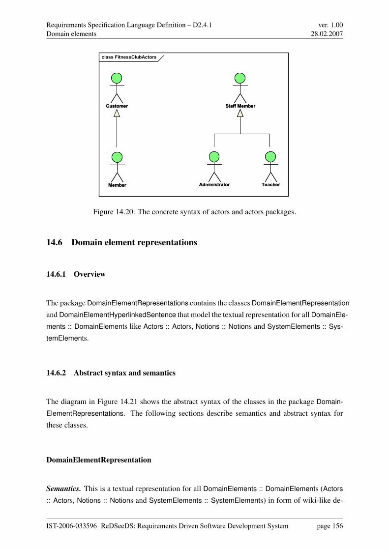
Requirements Specification Language Definition – D2.4.1Domain elements
ver. 1.0028.02.2007
class FitnessClubActors
Customer
Member
Staff Member
Administrator Teacher
Customer
Member
Staff Member
Administrator Teacher
Figure 14.20: The concrete syntax of actors and actors packages.
14.6 Domain element representations
14.6.1 Overview
The package DomainElementRepresentations contains the classes DomainElementRepresentation
and DomainElementHyperlinkedSentence that model the textual representation for all DomainEle-
ments :: DomainElements like Actors :: Actors, Notions :: Notions and SystemElements :: Sys-
temElements.
14.6.2 Abstract syntax and semantics
The diagram in Figure 14.21 shows the abstract syntax of the classes in the package Domain-
ElementRepresentations. The following sections describe semantics and abstract syntax forthese classes.
DomainElementRepresentation
Semantics. This is a textual representation for all DomainElements :: DomainElements (Actors
:: Actors, Notions :: Notions and SystemElements :: SystemElements) in form of wiki-like de-
IST-2006-033596 ReDSeeDS: Requirements Driven Software Development System page 156
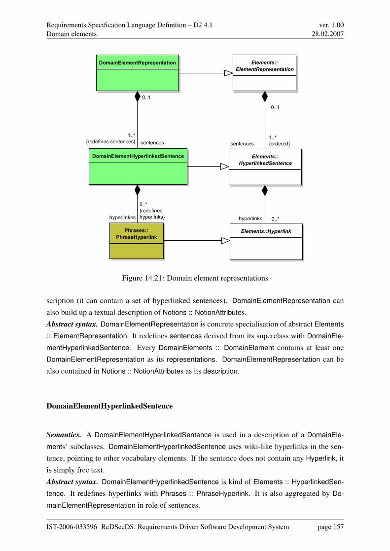
Requirements Specification Language Definition – D2.4.1Domain elements
ver. 1.0028.02.2007
Elements::
HyperlinkedSentence
Elements::Hyperlink
DomainElementRepresentation
DomainElementHyperlinkedSentence
Phrases::
PhraseHyperlink
Elements::
ElementRepresentation
sentences
1..*
{ordered}
0..1
hyperlinks 0..*
sentences
1..*
{redefines sentences}
0..1
hyperlinkes
0..*
{redefines
hyperlinks}
Figure 14.21: Domain element representations
scription (it can contain a set of hyperlinked sentences). DomainElementRepresentation canalso build up a textual description of Notions :: NotionAttributes.Abstract syntax. DomainElementRepresentation is concrete specialisation of abstract Elements
:: ElementRepresentation. It redefines sentences derived from its superclass with DomainEle-
mentHyperlinkedSentence. Every DomainElements :: DomainElement contains at least oneDomainElementRepresentation as its representations. DomainElementRepresentation can bealso contained in Notions :: NotionAttributes as its description.
DomainElementHyperlinkedSentence
Semantics. A DomainElementHyperlinkedSentence is used in a description of a DomainEle-
ments’ subclasses. DomainElementHyperlinkedSentence uses wiki-like hyperlinks in the sen-tence, pointing to other vocabulary elements. If the sentence does not contain any Hyperlink, itis simply free text.Abstract syntax. DomainElementHyperlinkedSentence is kind of Elements :: HyperlinkedSen-
tence. It redefines hyperlinks with Phrases :: PhraseHyperlink. It is also aggregated by Do-
mainElementRepresentation in role of sentences.
IST-2006-033596 ReDSeeDS: Requirements Driven Software Development System page 157
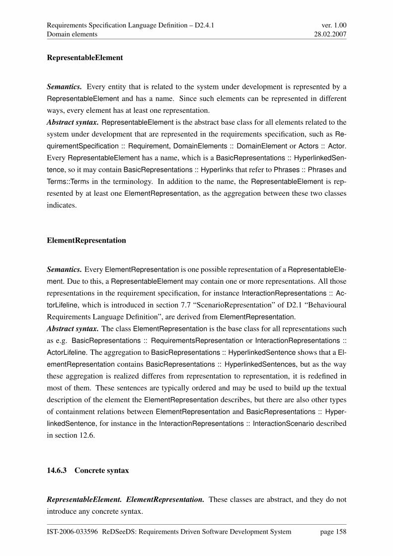
Requirements Specification Language Definition – D2.4.1Domain elements
ver. 1.0028.02.2007
RepresentableElement
Semantics. Every entity that is related to the system under development is represented by aRepresentableElement and has a name. Since such elements can be represented in differentways, every element has at least one representation.Abstract syntax. RepresentableElement is the abstract base class for all elements related to thesystem under development that are represented in the requirements specification, such as Re-
quirementSpecification :: Requirement, DomainElements :: DomainElement or Actors :: Actor.Every RepresentableElement has a name, which is a BasicRepresentations :: HyperlinkedSen-
tence, so it may contain BasicRepresentations :: Hyperlinks that refer to Phrases :: Phrases andTerms::Terms in the terminology. In addition to the name, the RepresentableElement is rep-resented by at least one ElementRepresentation, as the aggregation between these two classesindicates.
ElementRepresentation
Semantics. Every ElementRepresentation is one possible representation of a RepresentableEle-
ment. Due to this, a RepresentableElement may contain one or more representations. All thoserepresentations in the requirement specification, for instance InteractionRepresentations :: Ac-
torLifeline, which is introduced in section 7.7 “ScenarioRepresentation” of D2.1 “BehaviouralRequirements Language Definition”, are derived from ElementRepresentation.Abstract syntax. The class ElementRepresentation is the base class for all representations suchas e.g. BasicRepresentations :: RequirementsRepresentation or InteractionRepresentations ::
ActorLifeline. The aggregation to BasicRepresentations :: HyperlinkedSentence shows that a El-
ementRepresentation contains BasicRepresentations :: HyperlinkedSentences, but as the waythese aggregation is realized differes from representation to representation, it is redefined inmost of them. These sentences are typically ordered and may be used to build up the textualdescription of the element the ElementRepresentation describes, but there are also other typesof containment relations between ElementRepresentation and BasicRepresentations :: Hyper-
linkedSentence, for instance in the InteractionRepresentations :: InteractionScenario describedin section 12.6.
14.6.3 Concrete syntax
RepresentableElement. ElementRepresentation. These classes are abstract, and they do notintroduce any concrete syntax.
IST-2006-033596 ReDSeeDS: Requirements Driven Software Development System page 158
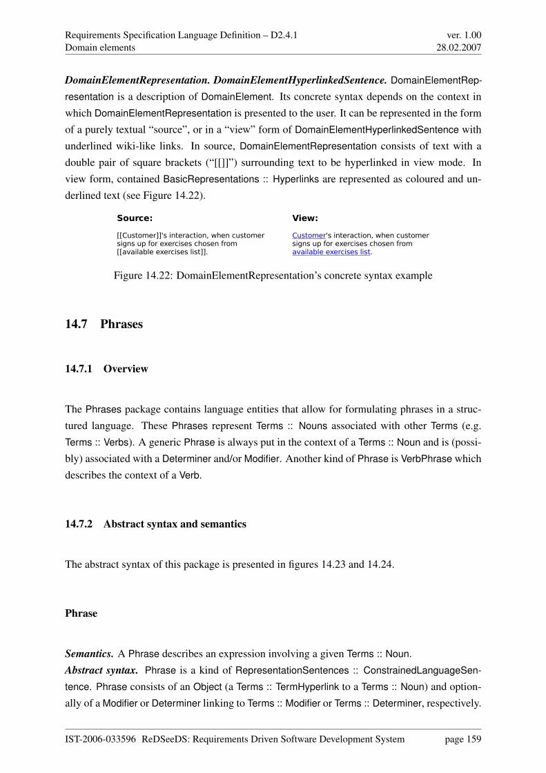
Requirements Specification Language Definition – D2.4.1Domain elements
ver. 1.0028.02.2007
DomainElementRepresentation. DomainElementHyperlinkedSentence. DomainElementRep-
resentation is a description of DomainElement. Its concrete syntax depends on the context inwhich DomainElementRepresentation is presented to the user. It can be represented in the formof a purely textual “source”, or in a “view” form of DomainElementHyperlinkedSentence withunderlined wiki-like links. In source, DomainElementRepresentation consists of text with adouble pair of square brackets (“[[]]”) surrounding text to be hyperlinked in view mode. Inview form, contained BasicRepresentations :: Hyperlinks are represented as coloured and un-derlined text (see Figure 14.22).
Source: View:
[[Customer]]'s interaction, when customer Customer's interaction, when customer signs up for exercises chosen from signs up for exercises chosen from [[available exercises list]]. available exercises list.
Figure 14.22: DomainElementRepresentation’s concrete syntax example
14.7 Phrases
14.7.1 Overview
The Phrases package contains language entities that allow for formulating phrases in a struc-tured language. These Phrases represent Terms :: Nouns associated with other Terms (e.g.Terms :: Verbs). A generic Phrase is always put in the context of a Terms :: Noun and is (possi-bly) associated with a Determiner and/or Modifier. Another kind of Phrase is VerbPhrase whichdescribes the context of a Verb.
14.7.2 Abstract syntax and semantics
The abstract syntax of this package is presented in figures 14.23 and 14.24.
Phrase
Semantics. A Phrase describes an expression involving a given Terms :: Noun.Abstract syntax. Phrase is a kind of RepresentationSentences :: ConstrainedLanguageSen-
tence. Phrase consists of an Object (a Terms :: TermHyperlink to a Terms :: Noun) and option-ally of a Modifier or Determiner linking to Terms :: Modifier or Terms :: Determiner, respectively.
IST-2006-033596 ReDSeeDS: Requirements Driven Software Development System page 159
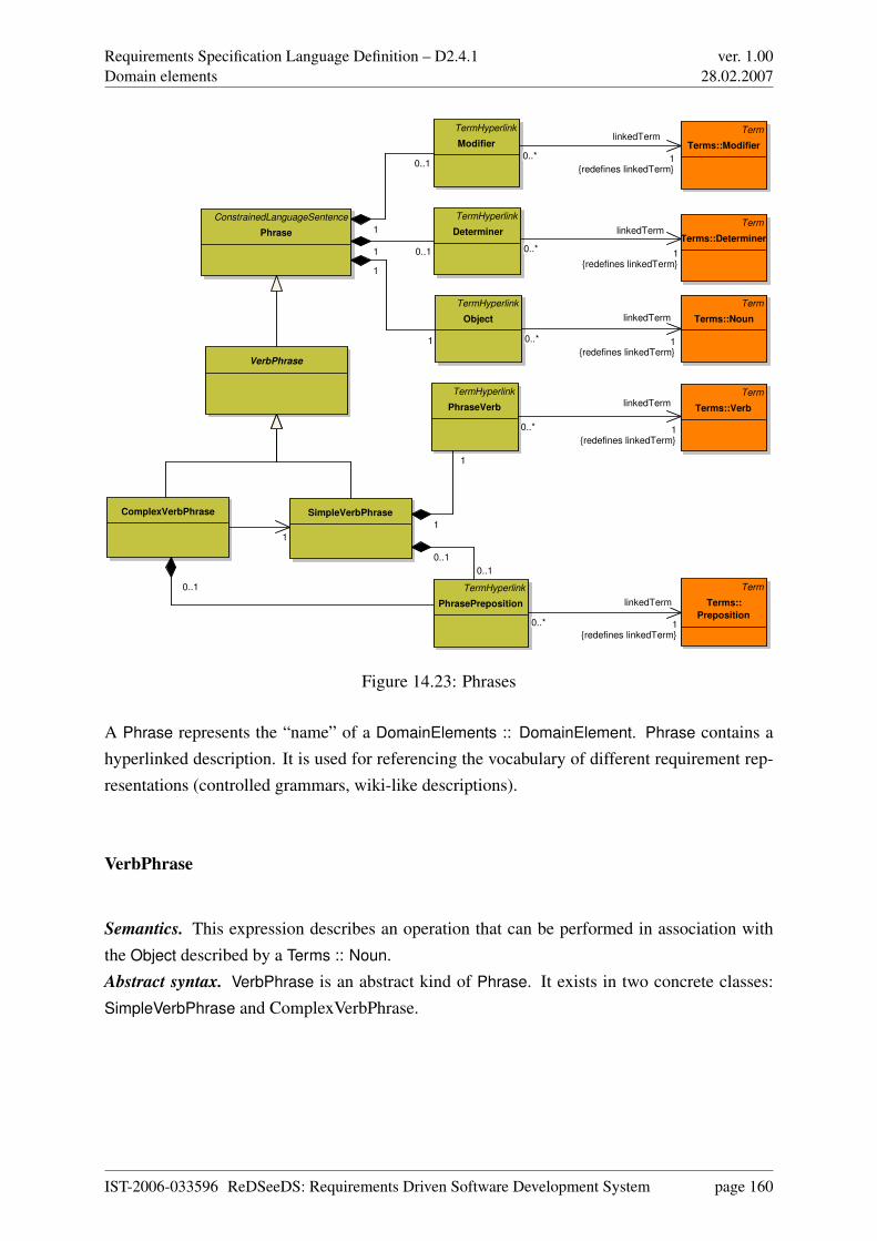
Requirements Specification Language Definition – D2.4.1Domain elements
ver. 1.0028.02.2007
ConstrainedLanguageSentence
Phrase
ComplexVerbPhrase SimpleVerbPhrase
Term
Terms::Noun
VerbPhrase
Term
Terms::Verb
Term
Terms::
Preposition
TermHyperlink
Modifier
TermHyperlink
Determiner
TermHyperlink
Object
TermHyperlink
PhraseVerb
TermHyperlink
PhrasePreposition
Term
Terms::Modifier
Term
Terms::Determiner
0..1
1
1
1
0..11
0..1
1
1
1
0..1
0..1
0..*
linkedTerm
1{redefines linkedTerm}
0..*
linkedTerm
1{redefines linkedTerm}
0..*
linkedTerm
1{redefines linkedTerm}
0..*
linkedTerm
1{redefines linkedTerm}
0..*
linkedTerm
1{redefines linkedTerm}
Figure 14.23: Phrases
A Phrase represents the “name” of a DomainElements :: DomainElement. Phrase contains ahyperlinked description. It is used for referencing the vocabulary of different requirement rep-resentations (controlled grammars, wiki-like descriptions).
VerbPhrase
Semantics. This expression describes an operation that can be performed in association withthe Object described by a Terms :: Noun.Abstract syntax. VerbPhrase is an abstract kind of Phrase. It exists in two concrete classes:SimpleVerbPhrase and ComplexVerbPhrase.
IST-2006-033596 ReDSeeDS: Requirements Driven Software Development System page 160
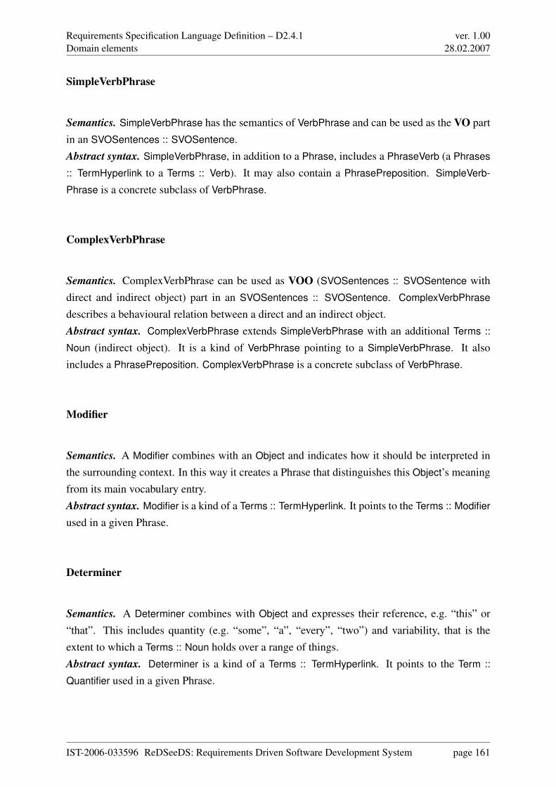
Requirements Specification Language Definition – D2.4.1Domain elements
ver. 1.0028.02.2007
SimpleVerbPhrase
Semantics. SimpleVerbPhrase has the semantics of VerbPhrase and can be used as the VO partin an SVOSentences :: SVOSentence.Abstract syntax. SimpleVerbPhrase, in addition to a Phrase, includes a PhraseVerb (a Phrases
:: TermHyperlink to a Terms :: Verb). It may also contain a PhrasePreposition. SimpleVerb-
Phrase is a concrete subclass of VerbPhrase.
ComplexVerbPhrase
Semantics. ComplexVerbPhrase can be used as VOO (SVOSentences :: SVOSentence withdirect and indirect object) part in an SVOSentences :: SVOSentence. ComplexVerbPhrase
describes a behavioural relation between a direct and an indirect object.Abstract syntax. ComplexVerbPhrase extends SimpleVerbPhrase with an additional Terms ::
Noun (indirect object). It is a kind of VerbPhrase pointing to a SimpleVerbPhrase. It alsoincludes a PhrasePreposition. ComplexVerbPhrase is a concrete subclass of VerbPhrase.
Modifier
Semantics. A Modifier combines with an Object and indicates how it should be interpreted inthe surrounding context. In this way it creates a Phrase that distinguishes this Object’s meaningfrom its main vocabulary entry.Abstract syntax. Modifier is a kind of a Terms :: TermHyperlink. It points to the Terms :: Modifier
used in a given Phrase.
Determiner
Semantics. A Determiner combines with Object and expresses their reference, e.g. “this” or“that”. This includes quantity (e.g. “some”, “a”, “every”, “two”) and variability, that is theextent to which a Terms :: Noun holds over a range of things.Abstract syntax. Determiner is a kind of a Terms :: TermHyperlink. It points to the Term ::
Quantifier used in a given Phrase.
IST-2006-033596 ReDSeeDS: Requirements Driven Software Development System page 161
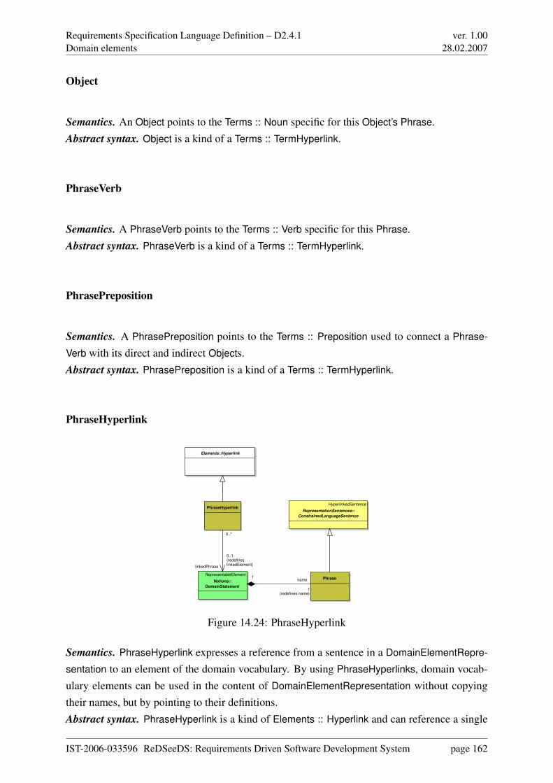
Requirements Specification Language Definition – D2.4.1Domain elements
ver. 1.0028.02.2007
Object
Semantics. An Object points to the Terms :: Noun specific for this Object’s Phrase.Abstract syntax. Object is a kind of a Terms :: TermHyperlink.
PhraseVerb
Semantics. A PhraseVerb points to the Terms :: Verb specific for this Phrase.Abstract syntax. PhraseVerb is a kind of a Terms :: TermHyperlink.
PhrasePreposition
Semantics. A PhrasePreposition points to the Terms :: Preposition used to connect a Phrase-
Verb with its direct and indirect Objects.Abstract syntax. PhrasePreposition is a kind of a Terms :: TermHyperlink.
PhraseHyperlink
Elements::Hyperlink
HyperlinkedSentence
RepresentationSentences::
ConstrainedLanguageSentence
PhraseRepresentableElement
Notions::
DomainStatement
PhraseHyperlink
0..*
linkedPhrase
0..1{redefineslinkedElement}
name
1{redefines name}
1
Figure 14.24: PhraseHyperlink
Semantics. PhraseHyperlink expresses a reference from a sentence in a DomainElementRepre-
sentation to an element of the domain vocabulary. By using PhraseHyperlinks, domain vocab-ulary elements can be used in the content of DomainElementRepresentation without copyingtheir names, but by pointing to their definitions.Abstract syntax. PhraseHyperlink is a kind of Elements :: Hyperlink and can reference a single
IST-2006-033596 ReDSeeDS: Requirements Driven Software Development System page 162
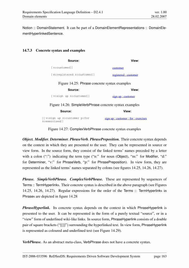
Requirements Specification Language Definition – D2.4.1Domain elements
ver. 1.0028.02.2007
Notion :: DomainStatement. It can be part of a DomainElementRepresentations :: DomainEle-
mentHyperlinkedSentence.
14.7.3 Concrete syntax and examples
Source: View:
[[n:customer]] customer
[[m:registered n:customer]] registered : customer
Figure 14.25: Phrase concrete syntax examples
Source: View:
[[v:sign up n:customer]] sign up : customer
Figure 14.26: SimpleVerbPhrase concrete syntax examples
Source: View:
[[v:sign up n:customer p:for n:exercises]]
sign up : customer : for : exercises
Figure 14.27: ComplexVerbPhrase concrete syntax examples
Object. Modifier. Determiner. PhraseVerb. PhrasePreposition. Their concrete syntax dependson the context in which they are presented to the user. They can be represented in source orview form. In the source form, they consist of the linked terms’ names preceded by a letterwith a colon (“:”) indicating the term type (“n:” for noun (Object), “m:” for Modifier, “d:”for Determiner, “v:” for PhraseVerb, “p:” for PhrasePreposition). In view form, they arerepresented as the linked terms’ names separated by colons (see figures 14.25, 14.26, 14.27).
Phrase. SimpleVerbPhrase. ComplexVerbPhrase. These are represented by sequences ofTerms :: TermHyperlinks. Their concrete syntax is described in the above paragraph (see Figures14.25, 14.26, 14.27). Regular expressions for the order of the Terms :: TermHyperlinks inPhrases are depicted in figure 14.28
PhraseHyperlink. Its concrete syntax depends on the context in which PhraseHyperlink ispresented to the user. It can be represented in the form of a purely textual “source”, or in a“view” form of underlined wiki-like links. In source form, PhraseHyperlink consists of a doublepair of square brackets (“[[]]”) surrounding the hyperlinked text. In view form, PhraseHyperlink
is represented as coloured and underlined text (see Figure 14.29).
VerbPhrase. As an abstract meta-class, VerbPhrase does not have a concrete syntax.
IST-2006-033596 ReDSeeDS: Requirements Driven Software Development System page 163
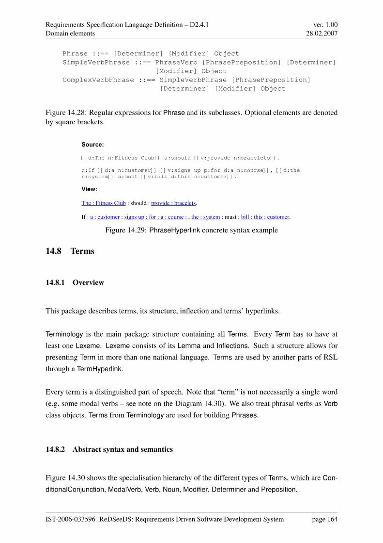
Requirements Specification Language Definition – D2.4.1Domain elements
ver. 1.0028.02.2007
Phrase ::== [Determiner] [Modifier] ObjectSimpleVerbPhrase ::== PhraseVerb [PhrasePreposition] [Determiner]
[Modifier] ObjectComplexVerbPhrase ::== SimpleVerbPhrase [PhrasePreposition]
[Determiner] [Modifier] Object
Figure 14.28: Regular expressions for Phrase and its subclasses. Optional elements are denotedby square brackets.
Source:
[[d:The n:Fitness Club]] a:should [[v:provide n:bracelets]].
c:If [[d:a n:customer]] [[v:signs up p:for d:a n:course]], [[d:the n:system]] a:must [[v:bill d:this n:customer]].
View:
The : Fitness Club : should : provide : bracelets.
If : a : customer : signs up : for : a : course : , the : system : must : bill : this : customer.
Figure 14.29: PhraseHyperlink concrete syntax example
14.8 Terms
14.8.1 Overview
This package describes terms, its structure, inflection and terms’ hyperlinks.
Terminology is the main package structure containing all Terms. Every Term has to have atleast one Lexeme. Lexeme consists of its Lemma and Inflections. Such a structure allows forpresenting Term in more than one national language. Terms are used by another parts of RSLthrough a TermHyperlink.
Every term is a distinguished part of speech. Note that “term” is not necessarily a single word(e.g. some modal verbs – see note on the Diagram 14.30). We also treat phrasal verbs as Verb
class objects. Terms from Terminology are used for building Phrases.
14.8.2 Abstract syntax and semantics
Figure 14.30 shows the specialisation hierarchy of the different types of Terms, which are Con-
ditionalConjunction, ModalVerb, Verb, Noun, Modifier, Determiner and Preposition.
IST-2006-033596 ReDSeeDS: Requirements Driven Software Development System page 164
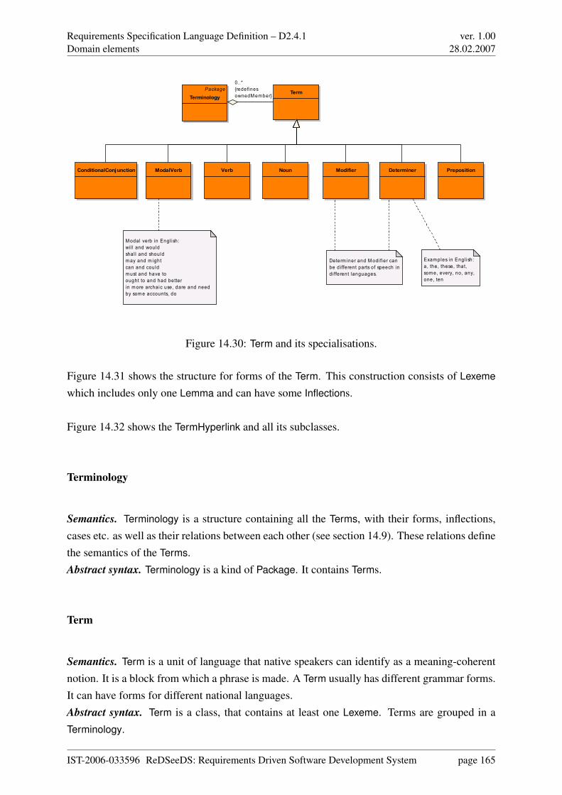
Requirements Specification Language Definition – D2.4.1Domain elements
ver. 1.0028.02.2007
Verb Noun
Term
PrepositionModalVerb
M odal verb in Engl ish: wi l l and wouldshal l and shouldm ay and m ightcan and couldm ust and have toought to and had betterin m ore archaic use, dare and needby som e accounts, do
PackageTerminology
ConditionalConjunction Modifier Determiner
Determ iner and M odi fier can be d i fferent parts of speech in di fferent languages.
Exam ples in Engl ish:a, the, these, that, som e, every, no, any, one, ten
0..*{redefinesownedM em ber}
Figure 14.30: Term and its specialisations.
Figure 14.31 shows the structure for forms of the Term. This construction consists of Lexeme
which includes only one Lemma and can have some Inflections.
Figure 14.32 shows the TermHyperlink and all its subclasses.
Terminology
Semantics. Terminology is a structure containing all the Terms, with their forms, inflections,cases etc. as well as their relations between each other (see section 14.9). These relations definethe semantics of the Terms.Abstract syntax. Terminology is a kind of Package. It contains Terms.
Term
Semantics. Term is a unit of language that native speakers can identify as a meaning-coherentnotion. It is a block from which a phrase is made. A Term usually has different grammar forms.It can have forms for different national languages.Abstract syntax. Term is a class, that contains at least one Lexeme. Terms are grouped in aTerminology.
IST-2006-033596 ReDSeeDS: Requirements Driven Software Development System page 165
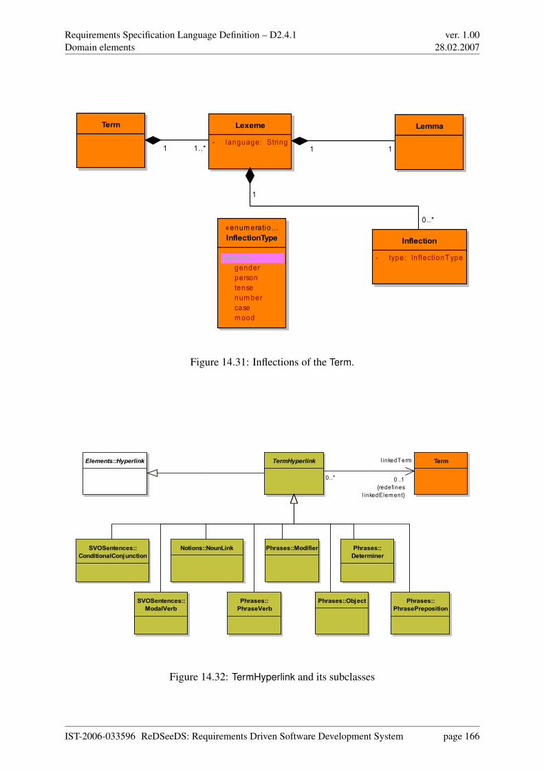
Requirements Specification Language Definition – D2.4.1Domain elements
ver. 1.0028.02.2007
Term Lexeme
- language: String
Lemma
Inflection
- type: In flectionT ype
«enum eratio...InflectionType
«enum » gender person tense num ber case m ood
1..*1
0..*
1
11
Figure 14.31: Inflections of the Term.
Elements::Hyperlink Term
Phrases::Object
Phrases::Modifier Phrases::Determiner
Phrases::PhraseVerb
Phrases::PhrasePreposition
SVOSentences::ModalVerb
Notions::NounLink
TermHyperlink
SVOSentences::ConditionalConjunction
0..*
l inkedTerm
0..1{redefines
l inkedElement}
Figure 14.32: TermHyperlink and its subclasses
IST-2006-033596 ReDSeeDS: Requirements Driven Software Development System page 166

Requirements Specification Language Definition – D2.4.1Domain elements
ver. 1.0028.02.2007
Lexeme
Semantics. Lexeme is an abstract unit of morphological analysis in linguistics. It is character-istic for national language. It can be understood as a set of forms, inflections of the same Term.Abstract syntax. Lexeme is a component of Term. It consists of only one Lemma and some In-
flections. This class has an attribute “language” of type String determining the national languageof the Lexeme.
Lemma
Semantics. Lemma represents the canonical form of a Lexeme.Abstract syntax. This class is a component of Lexeme. Lexeme can have only one Lemma.
Inflection
Semantics. Inflection is modification of a Term (or more precisely Lemma) reflecting a gram-matical information. Grammatical form is constrained by InflectionType gender, tense, number,person, case, mood.Abstract syntax. This class is a composite of Lexeme. Lexeme has at least one Inflection, theLemma.
InflectionType
Semantics. InflectionType determines type of Term’s inflection type. Possible types of inflec-tions are: gender, tense, number, person, case, mood.Abstract syntax. InflectionType is an enumerator which defines values: gender, tense, number,person, case, mood.
ConditionalConjunction
Semantics. A ConditionalConjunction is a Terminology element used for combining two sen-tences into a conditional or state descriptive structure.Abstract syntax. ConditionalConjunction is a kind of a Term.
IST-2006-033596 ReDSeeDS: Requirements Driven Software Development System page 167
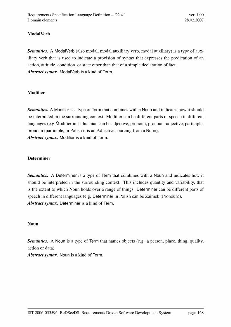
Requirements Specification Language Definition – D2.4.1Domain elements
ver. 1.0028.02.2007
ModalVerb
Semantics. A ModalVerb (also modal, modal auxiliary verb, modal auxiliary) is a type of aux-iliary verb that is used to indicate a provision of syntax that expresses the predication of anaction, attitude, condition, or state other than that of a simple declaration of fact.Abstract syntax. ModalVerb is a kind of Term.
Modifier
Semantics. A Modifier is a type of Term that combines with a Noun and indicates how it shouldbe interpreted in the surrounding context. Modifier can be different parts of speech in differentlanguages (e.g.Modifier in Lithuanian can be adjective, pronoun, pronoun+adjective, participle,pronoun+participle, in Polish it is an Adjective sourcing from a Noun).Abstract syntax. Modifier is a kind of Term.
Determiner
Semantics. A Determiner is a type of Term that combines with a Noun and indicates how itshould be interpreted in the surrounding context. This includes quantity and variability, thatis the extent to which Noun holds over a range of things. Determiner can be different parts ofspeech in different languages (e.g. Determiner in Polish can be Zaimek (Pronoun)).Abstract syntax. Determiner is a kind of Term.
Noun
Semantics. A Noun is a type of Term that names objects (e.g. a person, place, thing, quality,action or data).Abstract syntax. Noun is a kind of Term.
IST-2006-033596 ReDSeeDS: Requirements Driven Software Development System page 168

Requirements Specification Language Definition – D2.4.1Domain elements
ver. 1.0028.02.2007
Preposition
Semantics. A Preposition is a type of Term that combines with Phrases :: Phrases and indicateshow they should be interpreted in the surrounding context.Abstract syntax. Preposition is a kind of Term.
Verb
Semantics. A Verb is a type of a Term that expresses action or state of being.Abstract syntax. Verb is a kind of a Term.
TermHyperlink
Semantics. A TermHyperlink denotes a reference to a Term. Using instances of the various sub-classes of TermHyperlink, Terms can be used in Phrases, SVOSentences, Notions by pointingto them.Abstract syntax. The abstract meta-class TermHyperlink is a kind of Elements :: Hyperlink. Itcan reference a single Term.
14.8.3 Concrete syntax and examples
Terminology. It is a semantic structure that holds Terms. This structure should allow forsemantic-based reuse of organisation-specific Terms. The concrete syntax is equivalent to theconcrete syntax of the DomainVocabulary (compare Figure 14.33 and Figure 14.7) which isbased on Kernel :: Package. More important is the tree view presentation of the Terminology as
Figure 14.33: Package view: Terminology’s concrete syntax.
depicted in Figure 14.34. Please note that the tree view depicts only the specialisation relations.Therefore relations between Terms are not shown.
IST-2006-033596 ReDSeeDS: Requirements Driven Software Development System page 169
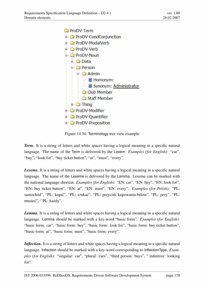
Requirements Specification Language Definition – D2.4.1Domain elements
ver. 1.0028.02.2007
Figure 14.34: Terminology tree view example
Term. It is a string of letters and white spaces having a logical meaning in a specific naturallanguage. The name of the Term is delivered by the Lexem. Examples (for English): “car”,“buy”, “look for”, “buy ticket button”, “at”, “must”, “every”.
Lexeme. It is a string of letters and white spaces having a logical meaning in a specific naturallanguage. The name of the Lexeme is delivered by the Lemma. Lexeme can be marked withthe national language shortcut. Examples (for English): “EN: car”, “EN: buy”, “EN: look for”,“EN: buy ticket button”, “EN: at”, “EN: must”, “EN: every”. Examples (for Polish): “PL:samochód”, “PL: kupic”, “PL: szukac”, “PL: przycisk kupowania biletu”, “PL: przy”, “PL:musiec”, ‘’PL: kazdy”.
Lemma. It is a string of letters and white spaces having a logical meaning in a specific naturallanguage. Lemma should be marked with a key-word “basic form”. Examples (for English):
“basic form: car”, “basic form: buy”, “basic form: look for”, “basic form: buy ticket button”,“basic form: at”, “basic form: must”, “basic form: every”.
Inflection. It is a string of letters and white spaces having a logical meaning in a specific naturallanguage. Inflection should be marked with a key-word corresponding to InflectionType. Exam-
ples (for English): “singular: car”, “plural: cars”, “third person: buys”, “ infinitive: lookingfor”.
IST-2006-033596 ReDSeeDS: Requirements Driven Software Development System page 170
Requirements Specification Language Definition – D2.4.1Domain elements
ver. 1.0028.02.2007
InflectionType. It is a string of letters and white spaces finished with a colon “:”, used in formu-lating a key-word used in describing Inflection. Examples (for English): “singular:”, “plural:”,“third person:”, “infinitive:”.
Conditional Conjunction. It is a string of letters and white spaces used in formulating con-ditional or state descriptive clauses. Examples (for English): “if”, “when”, “upon”, “after”,“during”.
ModalVerb. It is a string of letters and white spaces used in formulating a modal form. Examples
(for English): “will”/“would”, “shall”, “should”, “may”/“might”, “can”/“could”, “must”, “haveto”, “ought to”.
Modifier. is a string of letters and white spaces used in describing (modifying the meaning of)a Noun. Examples (for English): “registered”, “fast”, “common”.
Determiner. is a string of letters and white spaces used in formulating a quantity and a variabil-ity of a Noun. Examples (for English): “every”, “one”, “each”.
Noun. It is a string of letters and white spaces used in formulating an objects’ description.Examples (for English): “user”, “system”, “buy ticket button”, “accessibility”, “saving”
Preposition. It is a string of letters and white spaces used in formulating Phrases :: Phrases’
context. Examples (for English): “on”, “of”, “to”, “for”, “inside”, “next to”, “in accordancewith”
Verb. is a string of letters and white spaces used in formulating an action description. Examples
(for English): “add”, “show”, “save”, “start”, “provide”, “look for”, “choose between”
TermHyperlink. As an abstract meta-class, TermHyperlink does not have a concrete syntax.
14.9 TermsRelations
14.9.1 Overview
This package describes subclasses, that form the basic structure for thesaurus and ontology.TermSpecialisationRelation as well as HasSynonym and HasHomonym relations are seen as themain semantic information for Terms :: Term.
IST-2006-033596 ReDSeeDS: Requirements Driven Software Development System page 171
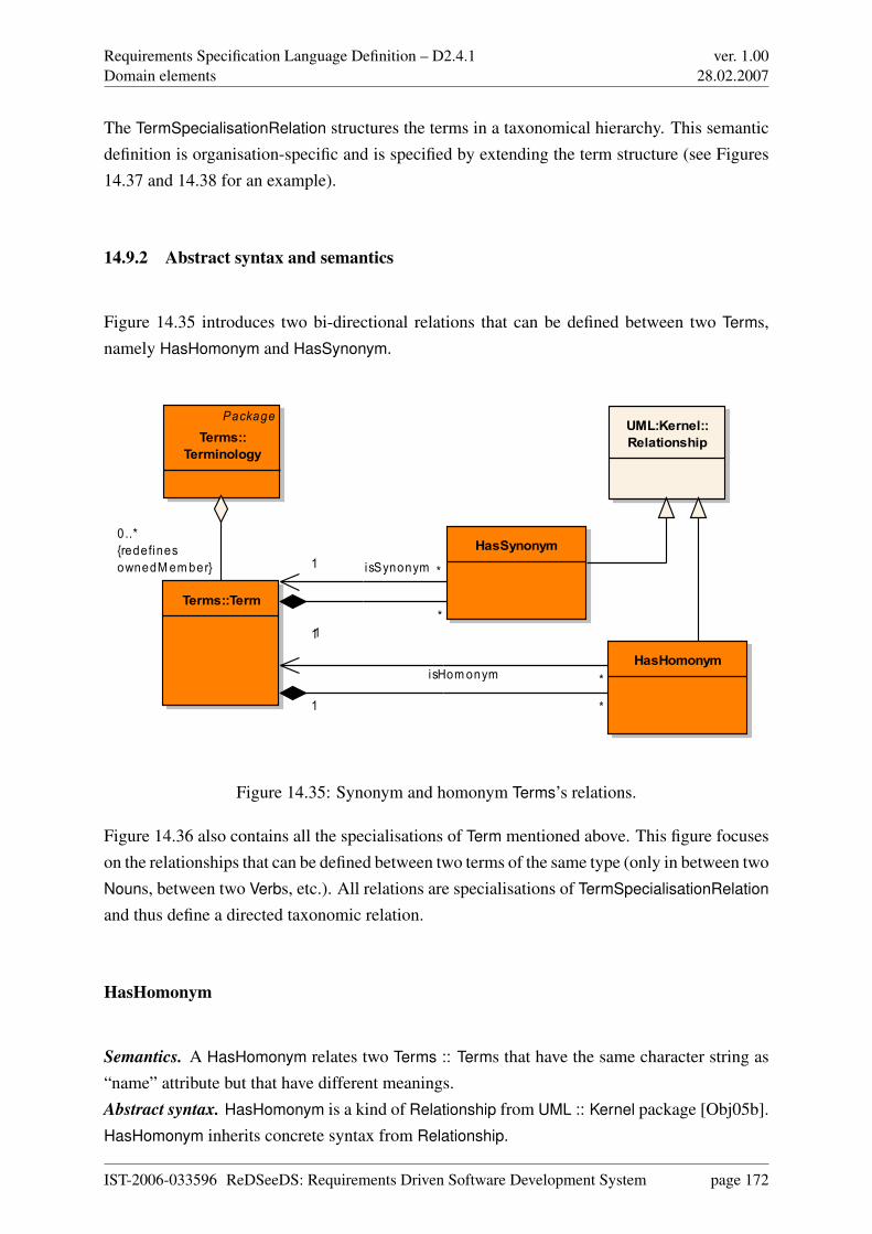
Requirements Specification Language Definition – D2.4.1Domain elements
ver. 1.0028.02.2007
The TermSpecialisationRelation structures the terms in a taxonomical hierarchy. This semanticdefinition is organisation-specific and is specified by extending the term structure (see Figures14.37 and 14.38 for an example).
14.9.2 Abstract syntax and semantics
Figure 14.35 introduces two bi-directional relations that can be defined between two Terms,namely HasHomonym and HasSynonym.
Terms::Term
PackageTerms::
Terminology
HasHomonym
HasSynonym
UML:Kernel::Relationship
*1
*1
0..*{redefinesownedMember}
1
isHomonym *
1 isSynonym *
Figure 14.35: Synonym and homonym Terms’s relations.
Figure 14.36 also contains all the specialisations of Term mentioned above. This figure focuseson the relationships that can be defined between two terms of the same type (only in between twoNouns, between two Verbs, etc.). All relations are specialisations of TermSpecialisationRelation
and thus define a directed taxonomic relation.
HasHomonym
Semantics. A HasHomonym relates two Terms :: Terms that have the same character string as“name” attribute but that have different meanings.Abstract syntax. HasHomonym is a kind of Relationship from UML :: Kernel package [Obj05b].HasHomonym inherits concrete syntax from Relationship.
IST-2006-033596 ReDSeeDS: Requirements Driven Software Development System page 172
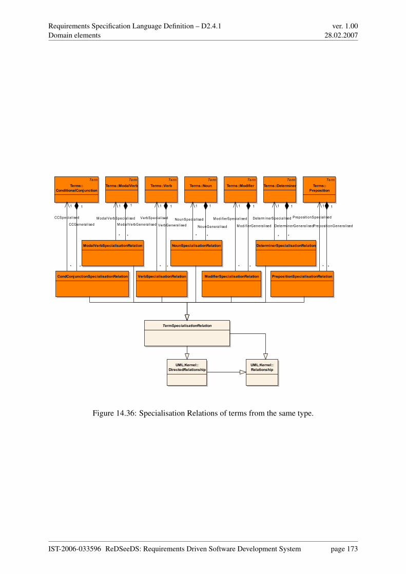
Requirements Specification Language Definition – D2.4.1Domain elements
ver. 1.0028.02.2007
TermTerms::Verb
TermTerms::Noun
TermTerms::Determiner
TermTerms::
Preposition
TermTerms::ModalVerb
TermTerms::Modifier
TermTerms::
ConditionalConjunction
NounSpecialisationRelation
VerbSpecialisationRelation
ModalVerbSpecialisationRelation
ModifierSpecialisationRelation
DeterminerSpecialisationRelation
PrepositionSpecialisationRelationCondConjunctionSpecialisationRelation
TermSpecialisationRelation
UML:Kernel::DirectedRelationship
UML:Kernel::Relationship
1
Determ inerSpecia l ised
*
1
Preposi tionSpecial ised
**
VerbGenera l ised
1 1
Modi fierSpecia l ised
*
1
ModalVerbSpecia l ised
*
1
VerbSpecial ised
*
1
NounSpecial ised
*
*
CCGeneral ised
1
*
Modi fierGenera l ised
1
*
ModalVerbGenera l ised
1
*
Preposi tionGenera l ised
1
*
Determ inerGenera l ised
1
*
NounGeneral ised
11
CCSpecial ised
*
Figure 14.36: Specialisation Relations of terms from the same type.
IST-2006-033596 ReDSeeDS: Requirements Driven Software Development System page 173
Requirements Specification Language Definition – D2.4.1Domain elements
ver. 1.0028.02.2007
HasSynonym
Semantics. A HasSynonym relates two Terms :: Terms that have the same meaning but adifferent character string as “name” attribute.Abstract syntax. HasSynonym is a kind of Relationship from UML :: Kernel package [Obj05b].HasSynonym inherits concrete syntax from Relationship.
TermSpecialisationRelation
Semantics. TermSpecialisationRelation is an abstract class that defines semantics for all otherrelation classes in this package other than HasHomonym and HasSynonym. TermSpecialisa-
tionRelation inherits concrete syntax from DirectRelationship. The subclasses of TermSpecial-
isationRelation are: CondConjunctionSpecialisationRelation, ModalVerbSpecialisationRelation,NounSpecialisationRelation, ModifierSpecialisationRelation, DeterminerSpecialisationRelation,PrepositionSpecialisationRelation. These relations define specific specialisation relations forthe diverse types of terms. Those subclasses ensure that the source and the target of the re-lationship are of the same kind of Terms :: Term. The source of each relationship should bedifferent from its target - Terms :: Term cannot be associated with itself.Abstract syntax. TermSpecialisationRelation is a kind of DirectRelationship from the UML ::
Kernel package [Obj05b].
CondConjunctionSpecialisationRelation
Semantics. A CondConjunctionSpecialisationRelation relates one Terms :: ConditionalConjunc-
tion (as the source of the relationship) to another Terms :: ConditionalConjunction (the target ofthe relationship).Abstract syntax. CondConjunctionSpecialisationRelation is a kind of TermSpecialisationRela-
tion.
ModalVerbSpecialisationRelation
Semantics. A ModalVerbSpecialisationRelation relates one Terms :: ModalVerb (as the sourceof the relationship) to another Terms :: ModalVerb (the target of the relationship).Abstract syntax. ModalVerbSpecialisationRelation is a kind of TermSpecialisationRelation.
IST-2006-033596 ReDSeeDS: Requirements Driven Software Development System page 174
Requirements Specification Language Definition – D2.4.1Domain elements
ver. 1.0028.02.2007
VerbSpecialisationRelation
Semantics. A VerbSpecialisationRelation relates one Terms :: Verb (as the source of the rela-tionship) to another Terms :: Verb (the target of the relationship).Abstract syntax. VerbSpecialisationRelation is a kind of TermSpecialisationRelation.
NounSpecialisationRelation
Semantics. A NounSpecialisationRelation relates one Terms :: Noun (as the source of the rela-tionship) to another Terms :: Noun (the target of the relationship).Abstract syntax. NounSpecialisationRelation is a kind of TermSpecialisationRelation.
ModifierSpecialisationRelation
Semantics. A ModifierSpecialisationRelation relates one Terms :: Modifier (as the source of therelationship) to another Terms :: Modifier (the target of the relationship).Abstract syntax. ModifierSpecialisationRelation is a kind of TermSpecialisationRelation.
DeterminerSpecialisationRelation
Semantics. A DeterminerSpecialisationRelation relates one Terms :: Determiner (as the sourceof the relationship) to another Terms :: Determiner (the target of the relationship).Abstract syntax. DeterminerSpecialisationRelation is a kind of TermSpecialisationRelation.
PrepositionSpecialisationRelation
Semantics. A PrepositionSpecialisationRelation relates one Terms :: Preposition (as the sourceof the relationship) to another Terms :: Preposition (the target of the relationship).Abstract syntax. PrepositionSpecialisationRelation is a kind of TermSpecialisationRelation.
IST-2006-033596 ReDSeeDS: Requirements Driven Software Development System page 175
Requirements Specification Language Definition – D2.4.1Domain elements
ver. 1.0028.02.2007
14.9.3 Concrete syntax and examples
HasSynonym. HasSynonym is presented in tree view as subelement (leaf) of Terms :: Term
(see Figure 14.34).
HasHomonym. HasHomonym is presented in tree view as subelement (leaf) of Terms :: Term
(see Figure 14.34).
TermSpecialisationRelation. As an abstract meta-class, TermSpecialisationRelation does nothave a concrete syntax. All specialisation classes of TermSpecialisationRelation are depicted asa package with a subpackages in the tree view of the Terminology (see Figure 14.34).
Figures 14.37 and 14.38 show the abstract syntax of a terminology with domain-specific exten-sions (for ProDV related terms in this case). Figure 14.37 depicts the noun related part of theterminology, while Figure 14.38 shows the verb related part respectively.
IST-2006-033596 ReDSeeDS: Requirements Driven Software Development System page 176
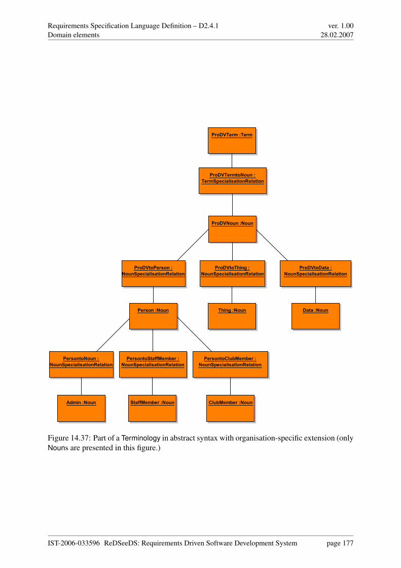
Requirements Specification Language Definition – D2.4.1Domain elements
ver. 1.0028.02.2007
ProDVNoun :Noun
Data :NounPerson :Noun Thing :Noun
Admin :Noun ClubMember :NounStaffMember :Noun
ProDVtoPerson :
NounSpecialisationRelation
ProDVtoThing :
NounSpecialisationRelation
ProDVtoData :
NounSpecialisationRelation
PersontoNoun :
NounSpecialisationRelation
PersontoClubMember :
NounSpecialisationRelation
PersontoStaffMember :
NounSpecialisationRelation
ProDVTerm :Term
ProDVTermtoNoun :
TermSpecialisationRelation
Figure 14.37: Part of a Terminology in abstract syntax with organisation-specific extension (onlyNouns are presented in this figure.)
IST-2006-033596 ReDSeeDS: Requirements Driven Software Development System page 177
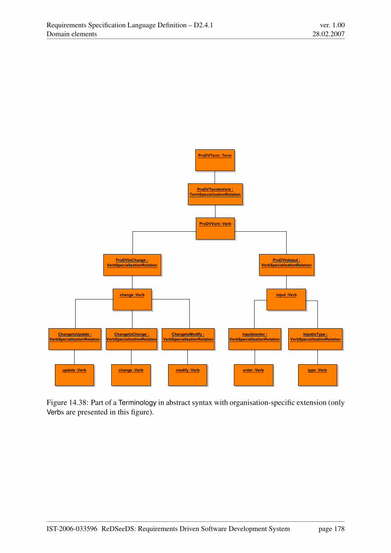
Requirements Specification Language Definition – D2.4.1Domain elements
ver. 1.0028.02.2007
ProDVVerb :Verb
change :Verb
update :Verb change :Verb modify :Verb
input :Verb
enter :Verb type :Verb
ProDVtoChange :
VerbSpecialisationRelation
ProDVtoInput :
VerbSpecialisationRelation
ChangetoUpdate :
VerbSpecialisationRelation
ChangetoChange :
VerbSpecialisationRelation
ChangetoModify :
VerbSpecialisationRelation
Inputtoenter :
VerbSpecialisationRelation
InputtoType :
VerbSpecialisationRelation
ProDVTerm :Term
ProDVTermtoVerb :
TermSpecialisationRelation
Figure 14.38: Part of a Terminology in abstract syntax with organisation-specific extension (onlyVerbs are presented in this figure).
IST-2006-033596 ReDSeeDS: Requirements Driven Software Development System page 178
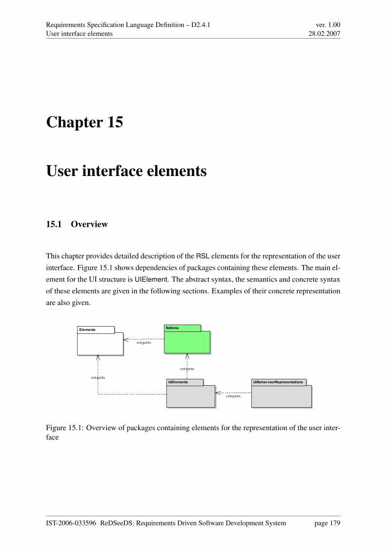
Requirements Specification Language Definition – D2.4.1User interface elements
ver. 1.0028.02.2007
Chapter 15
User interface elements
15.1 Overview
This chapter provides detailed description of the RSL elements for the representation of the userinterface. Figure 15.1 shows dependencies of packages containing these elements. The main el-ement for the UI structure is UIElement. The abstract syntax, the semantics and concrete syntaxof these elements are given in the following sections. Examples of their concrete representationare also given.
UIElements
NotionsElements
UIBehaviourRepresentations
«import»
«import»
« import»
« import»
Figure 15.1: Overview of packages containing elements for the representation of the user inter-face
IST-2006-033596 ReDSeeDS: Requirements Driven Software Development System page 179
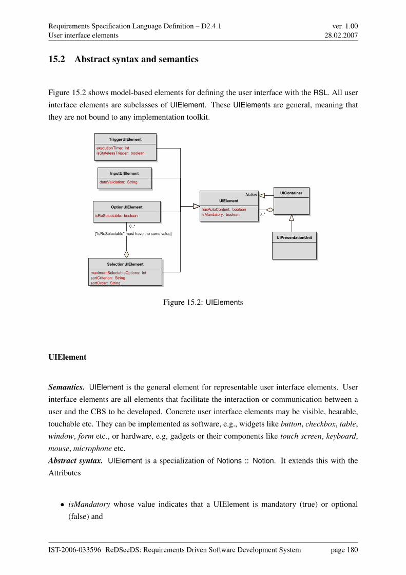
Requirements Specification Language Definition – D2.4.1User interface elements
ver. 1.0028.02.2007
15.2 Abstract syntax and semantics
Figure 15.2 shows model-based elements for defining the user interface with the RSL. All userinterface elements are subclasses of UIElement. These UIElements are general, meaning thatthey are not bound to any implementation toolkit.
Notion
UIElement
hasAutoContent: boolean
isMandatory: boolean
InputUIElement
dataValidation: String
OptionUIElement
isReSelectable: boolean
SelectionUIElement
maximumSelectableOptions: int
sortCriterion: String
sortOrder: String
TriggerUIElement
executionTime: int
isStatelessTrigger: boolean
UIContainer
UIPresentationUnit
0..*
0..*
{"isReSelectable" must have the same value}
Figure 15.2: UIElements
UIElement
Semantics. UIElement is the general element for representable user interface elements. Userinterface elements are all elements that facilitate the interaction or communication between auser and the CBS to be developed. Concrete user interface elements may be visible, hearable,touchable etc. They can be implemented as software, e.g., widgets like button, checkbox, table,window, form etc., or hardware, e.g, gadgets or their components like touch screen, keyboard,mouse, microphone etc.Abstract syntax. UIElement is a specialization of Notions :: Notion. It extends this with theAttributes
• isMandatory whose value indicates that a UIElement is mandatory (true) or optional(false) and
IST-2006-033596 ReDSeeDS: Requirements Driven Software Development System page 180
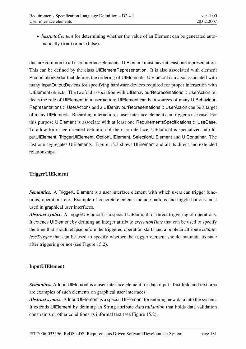
Requirements Specification Language Definition – D2.4.1User interface elements
ver. 1.0028.02.2007
• hasAutoContent for determining whether the value of an Element can be generated auto-matically (true) or not (false).
that are common to all user interface elements. UIElement must have at least one representation.This can be defined by the class UIElementRepresentation. It is also associated with elementPresentationOrder that defines the ordering of UIElements. UIElement can also associated withmany InputOutputDevices for specifying hardware devices required for proper interaction withUIElement objects. The twofold association with UIBehaviourRepresentations :: UserAction re-flects the role of UIElement in a user action; UIElement can be a sources of many UIBehaviour-
Representations :: UserActions and a UIBehaviourRepresentations :: UserAction can be a targetof many UIElements. Regarding interaction, a user interface element can trigger a use case. Forthis purpose UIElement is associate with at least one RequirementsSpecifications :: UseCase.To allow for usage oriented definition of the user interface, UIElement is specialized into In-
putUIElement, TriggerUIElement, OptionUIElement, SelectionUIElement and UIContainer. Thelast one aggregates UIElements. Figure 15.3 shows UIElement and all its direct and extendedrelationships.
TriggerUIElement
Semantics. A TriggerUIElement is a user interface element with which users can trigger func-tions, operations etc. Example of concrete elements include buttons and toggle buttons mostused in graphical user interfaces.Abstract syntax. A TriggerUIElement is a special UIElement for direct triggering of operations.It extends UIElement by defining an integer attribute executionTime that can be used to specifythe time that should elapse before the triggered operation starts and a boolean attribute isState-
lessTrigger that can be used to specify whether the trigger element should maintain its stateafter triggering or not (see Figure 15.2).
InputUIElement
Semantics. A InputUIElement is a user interface element for data input. Text field and text areaare examples of such elements on graphical user interfaces.Abstract syntax. A InputUIElement is a special UIElement for entering new data into the system.It extends UIElement by defining an String attribute dataValidation that holds data validationconstraints or other conditions as informal text (see Figure 15.2).
IST-2006-033596 ReDSeeDS: Requirements Driven Software Development System page 181
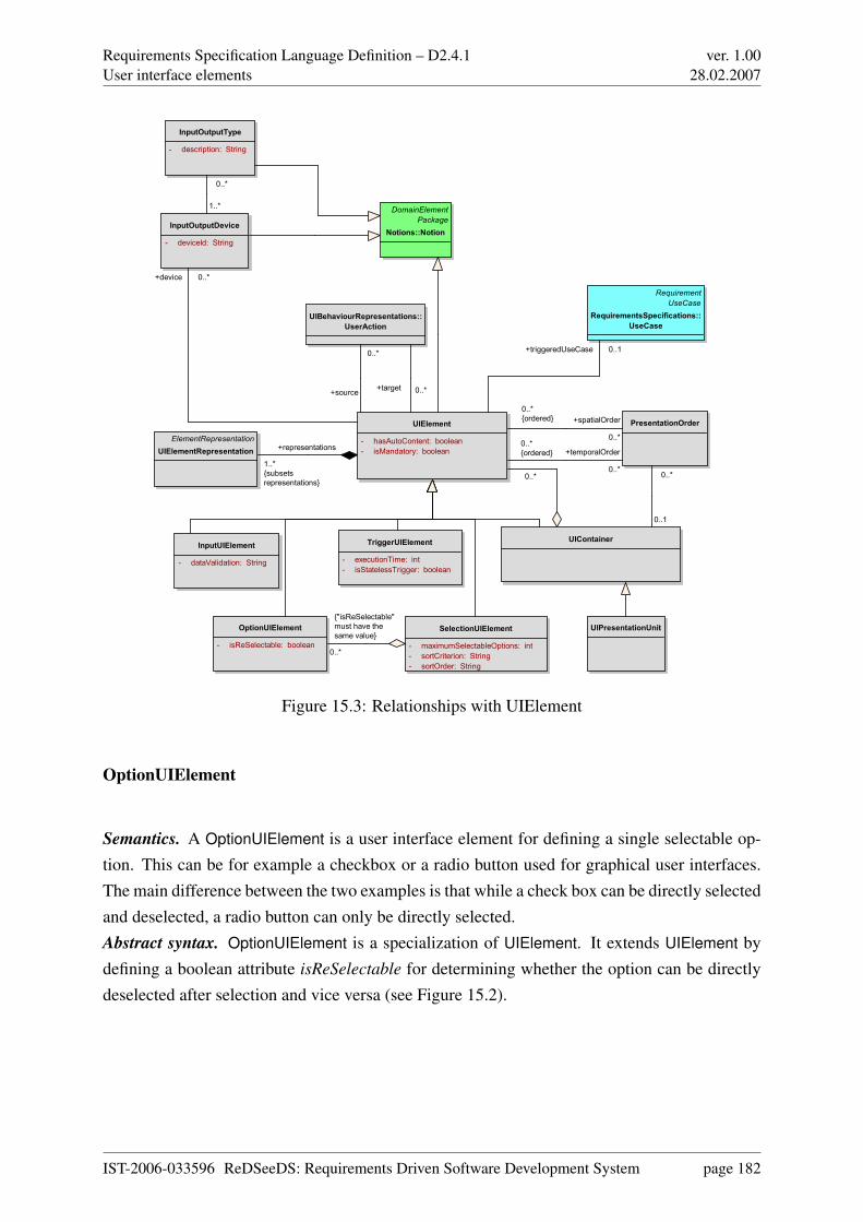
Requirements Specification Language Definition – D2.4.1User interface elements
ver. 1.0028.02.2007
UIElement
- hasAutoContent: boolean
- isMandatory: boolean
DomainElement
Package
Notions::NotionInputOutputDevice
- deviceId: String
InputUIElement
- dataValidation: String
OptionUIElement
- isReSelectable: boolean
PresentationOrder
SelectionUIElement
- maximumSelectableOptions: int
- sortCriterion: String
- sortOrder: String
TriggerUIElement
- executionTime: int
- isStatelessTrigger: boolean
UIContainer
ElementRepresentation
UIElementRepresentation
Requirement
UseCase
RequirementsSpecifications::
UseCase
UIBehaviourRepresentations::
UserAction
UIPresentationUnit
InputOutputType
- description: String
0..*
{"isReSelectable"
must have the
same value}
0..*
+source
1..*
{subsets
representations}
+representations
0..1
0..*
+temporalOrder
0..*
0..*
{ordered}
1..*
0..*
+target 0..*
+triggeredUseCase 0..1
0..*
+device 0..*
+spatialOrder
0..*
0..*
{ordered}
Figure 15.3: Relationships with UIElement
OptionUIElement
Semantics. A OptionUIElement is a user interface element for defining a single selectable op-tion. This can be for example a checkbox or a radio button used for graphical user interfaces.The main difference between the two examples is that while a check box can be directly selectedand deselected, a radio button can only be directly selected.Abstract syntax. OptionUIElement is a specialization of UIElement. It extends UIElement bydefining a boolean attribute isReSelectable for determining whether the option can be directlydeselected after selection and vice versa (see Figure 15.2).
IST-2006-033596 ReDSeeDS: Requirements Driven Software Development System page 182
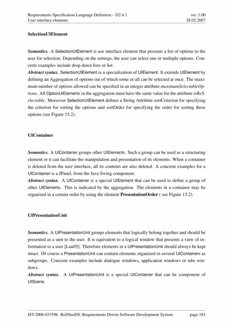
Requirements Specification Language Definition – D2.4.1User interface elements
ver. 1.0028.02.2007
SelectionUIElement
Semantics. A SelectionUIElement is use interface element that presents a list of options to theuser for selection. Depending on the settings, the user can select one or multiple options. Con-crete examples include drop down lists or list.Abstract syntax. SelectionUIElement is a specialization of UIElement. It extends UIElement bydefining an Aggregation of options out of which some or all can be selected at once. The maxi-mum number of options allowed can be specified in an integer attribute maximumSelectableOp-
tions. All OptionUIElements in the aggregation must have the same value for the attribute isReS-
electable. Moreover SelectionUIElement defines a String Attribute sortCriterion for specifyingthe criterion for sorting the options and sortOrder for specifying the order for sorting theseoptions (see Figure 15.2).
UIContainer
Semantics. A UIContainer groups other UIElements. Such a group can be used as a structuringelement or it can facilitate the manipulation and presentation of its elements. When a containeris deleted from the user interface, all its contents are also deleted. A concrete examples for aUIContainer is a JPanel, from the Java Swing component.Abstract syntax. A UIContainer is a special UIElement that can be used to define a group ofother UIElements. This is indicated by the aggregation. The elements in a container may beorganized in a certain order by using the element PresentationOrder ( see Figure 15.2).
UIPresentationUnit
Semantics. A UIPresentationUnit groups elements that logically belong together and should bepresented as a unit to the user. It is equivalent to a logical window that presents a view of in-formation to a user [Lau05]. Therefore elements in a UIPresentationUnit should always be keptintact. Of course a PresentationUnit can contain elements organized in several UIContainers assubgroups. Concrete examples include dialogue windows, application windows or tabs win-dows.Abstract syntax. A UIPresentationUnit is a special UIContainer that can be component ofUIScene.
IST-2006-033596 ReDSeeDS: Requirements Driven Software Development System page 183
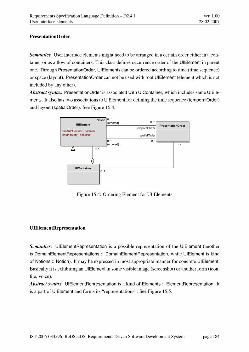
Requirements Specification Language Definition – D2.4.1User interface elements
ver. 1.0028.02.2007
PresentationOrder
Semantics. User interface elements might need to be arranged in a certain order either in a con-tainer or as a flow of containers. This class defines occurrence order of the UIElement in parentone. Through PresentationOrder, UIElements can be ordered according to time (time sequence)or space (layout). PresentationOrder can not be used with root UIElement (element which is notincluded by any other).Abstract syntax. PresentationOrder is associated with UIContainer, which includes same UIEle-
ments. It also has two associations to UIElement for defining the time sequence (temporalOrder)and layout (spatialOrder). See Figure 15.4.
Notion
UIElement
hasAutoContent: boolean
isMandatory: boolean
UIContainer
PresentationOrder
0..*
0..1
0..*
temporalOrder
0..*0..*
{ordered}
spatialOrder
0..*0..*
{ordered}
Figure 15.4: Ordering Element for UI Elements
UIElementRepresentation
Semantics. UIElementRepresentation is a possible representation of the UIElement (anotheris DomainElementRepresentations :: DomainElementRepresentation, while UIElement is kindof Notions :: Notion). It may be expressed in most appropriate manner for concrete UIElement.Basically it is exhibiting an UIElement in some visible image (screenshot) or another form (icon,file, voice).Abstract syntax. UIElementRepresentation is a kind of Elements :: ElementRepresentation. Itis a part of UIElement and forms its “representations”. See Figure 15.5.
IST-2006-033596 ReDSeeDS: Requirements Driven Software Development System page 184
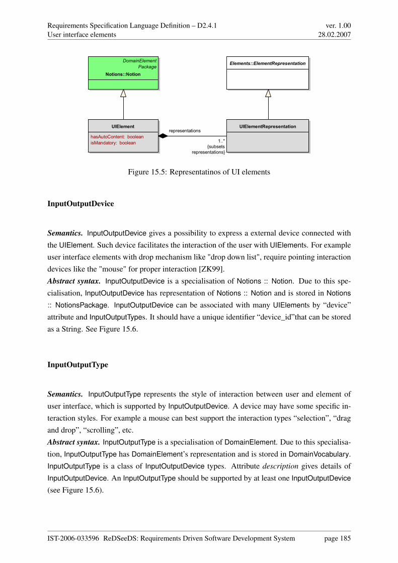
Requirements Specification Language Definition – D2.4.1User interface elements
ver. 1.0028.02.2007
UIElement
hasAutoContent: boolean
isMandatory: boolean
UIElementRepresentation
DomainElement
Package
Notions::Notion
Elements::ElementRepresentation
1..*
{subsets
representations}
representations
Figure 15.5: Representatinos of UI elements
InputOutputDevice
Semantics. InputOutputDevice gives a possibility to express a external device connected withthe UIElement. Such device facilitates the interaction of the user with UIElements. For exampleuser interface elements with drop mechanism like "drop down list", require pointing interactiondevices like the "mouse" for proper interaction [ZK99].Abstract syntax. InputOutputDevice is a specialisation of Notions :: Notion. Due to this spe-cialisation, InputOutputDevice has representation of Notions :: Notion and is stored in Notions
:: NotionsPackage. InputOutputDevice can be associated with many UIElements by “device”attribute and InputOutputTypes. It should have a unique identifier “device_id”that can be storedas a String. See Figure 15.6.
InputOutputType
Semantics. InputOutputType represents the style of interaction between user and element ofuser interface, which is supported by InputOutputDevice. A device may have some specific in-teraction styles. For example a mouse can best support the interaction types “selection”, “dragand drop”, “scrolling”, etc.Abstract syntax. InputOutputType is a specialisation of DomainElement. Due to this specialisa-tion, InputOutputType has DomainElement’s representation and is stored in DomainVocabulary.InputOutputType is a class of InputOutputDevice types. Attribute description gives details ofInputOutputDevice. An InputOutputType should be supported by at least one InputOutputDevice
(see Figure 15.6).
IST-2006-033596 ReDSeeDS: Requirements Driven Software Development System page 185
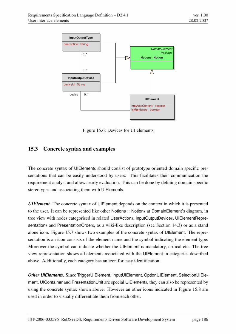
Requirements Specification Language Definition – D2.4.1User interface elements
ver. 1.0028.02.2007
InputOutputDevice
deviceId: String
InputOutputType
description: String
UIElement
hasAutoContent: boolean
isMandatory: boolean
DomainElement
Package
Notions::Notion
1..*
0..*
device 0..*
Figure 15.6: Devices for UI elements
15.3 Concrete syntax and examples
The concrete syntax of UIElements should consist of prototype oriented domain specific pre-sentations that can be easily understood by users. This facilitates their communication therequirement analyst and allows early evaluation. This can be done by defining domain specificstereotypes and associating them with UIElements.
UIElement. The concrete syntax of UIElement depends on the context in which it is presentedto the user. It can be represented like other Notions :: Notions at DomainElement’s diagram, intree view with nodes categorised in related UserActions, InputOutputDevices, UIElementRepre-
sentations and PresentationOrders, as a wiki-like description (see Section 14.3) or as a standalone icon. Figure 15.7 shows two examples of the concrete syntax of UIElement. The repre-sentation is an icon consists of the element name and the symbol indicating the element type.Moreover the symbol can indicate whether the UIElement is mandatory, critical etc. The treeview representation shows all elements associated with the UIElement in categeries describedabove. Additionally, each category has an icon for easy identification.
Other UIElements. Since TriggerUIElement, InputUIElement, OptionUIElement, SelectionUIEle-
ment, UIContainer and PresentationUnit are special UIElements, they can also be represented byusing the concrete syntax shown above. However an other icons indicated in Figure 15.8 areused in order to visually differentiate them from each other.
IST-2006-033596 ReDSeeDS: Requirements Driven Software Development System page 186
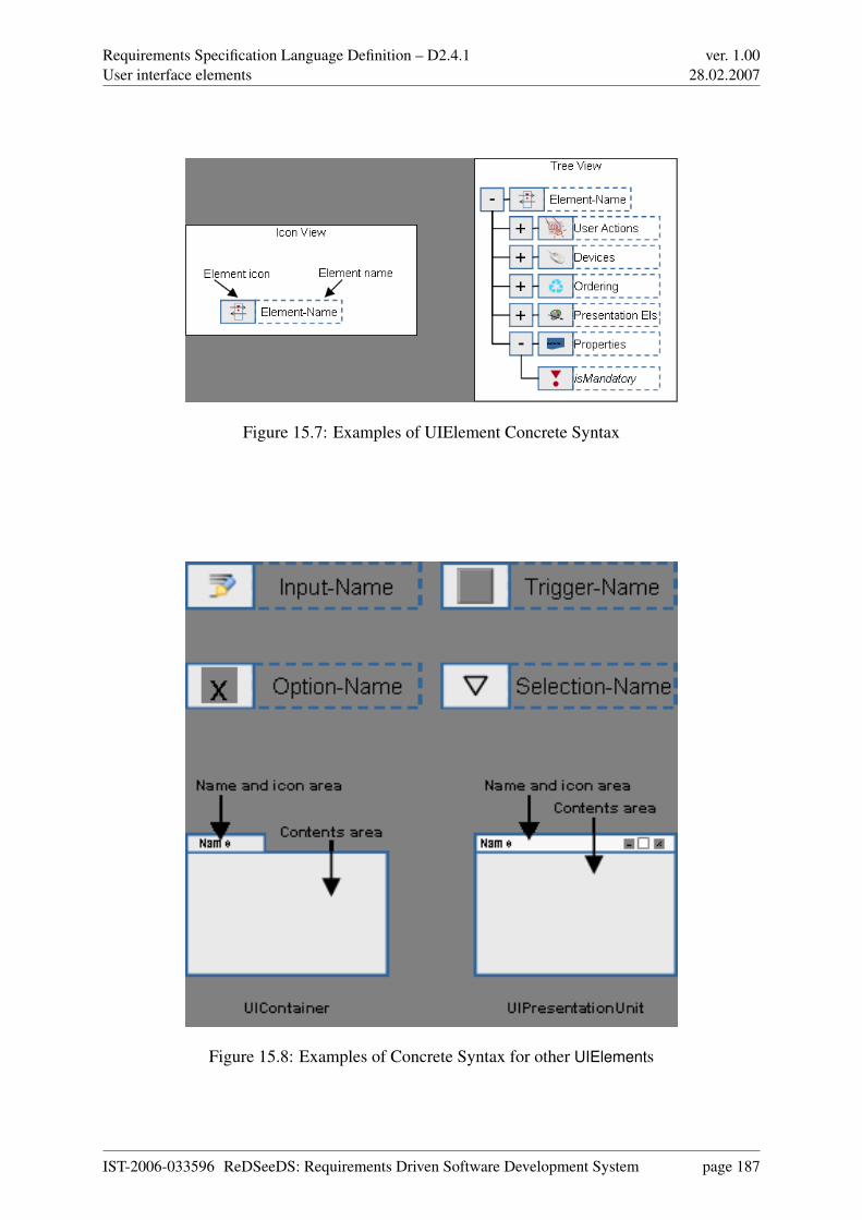
Requirements Specification Language Definition – D2.4.1User interface elements
ver. 1.0028.02.2007
Figure 15.7: Examples of UIElement Concrete Syntax
Figure 15.8: Examples of Concrete Syntax for other UIElements
IST-2006-033596 ReDSeeDS: Requirements Driven Software Development System page 187
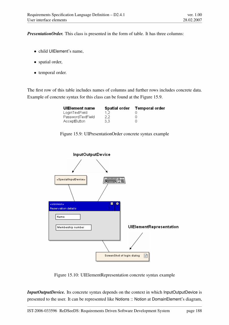
Requirements Specification Language Definition – D2.4.1User interface elements
ver. 1.0028.02.2007
PresentationOrder. This class is presented in the form of table. It has three columns:
• child UIElement’s name,
• spatial order,
• temporal order.
The first row of this table includes names of columns and further rows includes concrete data.Example of concrete syntax for this class can be found at the Figure 15.9.
Figure 15.9: UIPresentationOrder concrete syntax example
Figure 15.10: UIElementRepresentation concrete syntax example
InputOutputDevice. Its concrete syntax depends on the context in which InputOutputDevice ispresented to the user. It can be represented like Notions :: Notion at DomainElement’s diagram,
IST-2006-033596 ReDSeeDS: Requirements Driven Software Development System page 188
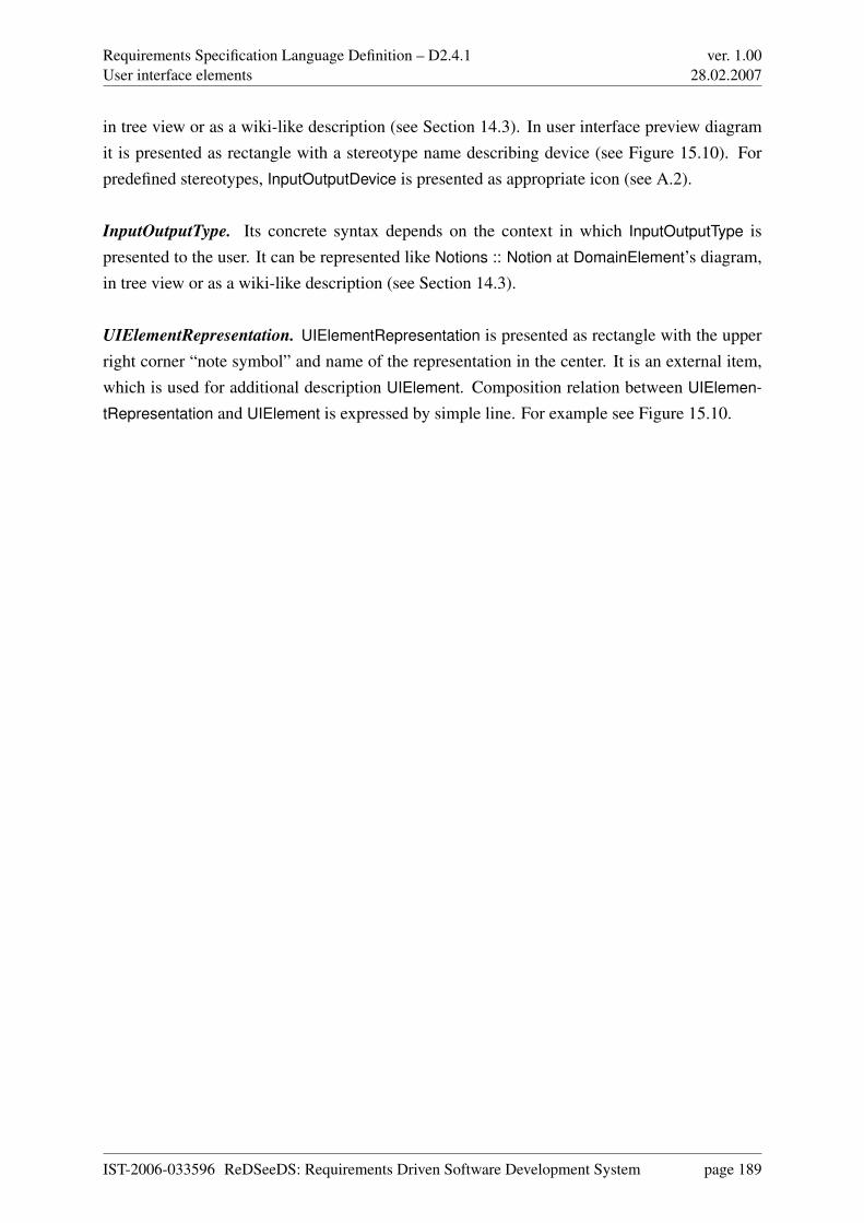
Requirements Specification Language Definition – D2.4.1User interface elements
ver. 1.0028.02.2007
in tree view or as a wiki-like description (see Section 14.3). In user interface preview diagramit is presented as rectangle with a stereotype name describing device (see Figure 15.10). Forpredefined stereotypes, InputOutputDevice is presented as appropriate icon (see A.2).
InputOutputType. Its concrete syntax depends on the context in which InputOutputType ispresented to the user. It can be represented like Notions :: Notion at DomainElement’s diagram,in tree view or as a wiki-like description (see Section 14.3).
UIElementRepresentation. UIElementRepresentation is presented as rectangle with the upperright corner “note symbol” and name of the representation in the center. It is an external item,which is used for additional description UIElement. Composition relation between UIElemen-
tRepresentation and UIElement is expressed by simple line. For example see Figure 15.10.
IST-2006-033596 ReDSeeDS: Requirements Driven Software Development System page 189
Requirements Specification Language Definition – D2.4.1User interface behaviour representation
ver. 1.0028.02.2007
Chapter 16
User interface behaviour representation
16.1 Overview
This package describes the general structure of UI elements that are used to describe behaviourof user interface. UIBehaviourRepresentations :: UIStoryboard as the main element presentingbehaviour of user interface includes UIScenes connected to ScenarioSenteces :: SVOScenar-
ioSentence. Each UIScene is built from UIElements :: UIPresentationUnit enriched by descrip-tion and scene number. UIScenes are related through UserActions which represent the actionsof users in interaction with the system.UIPresentationUnit is a snapshot of the user interface of the system (in form of graphic, text,etc.) at each specific step of interaction between the user and the system. This is a part of theconcrete syntax of UIScene. The other part is the textual description and the number of thescene. A connection between UIScenes is presented as an arrowed line. All these elementstogether create the concrete syntax of UIBehaviourRepresentations :: UIStoryboard.
16.2 Abstract syntax and semantics
Abstract syntax for the UIBehaviourRepresentations package is described in Figure 16.1.
IST-2006-033596 ReDSeeDS: Requirements Driven Software Development System page 190
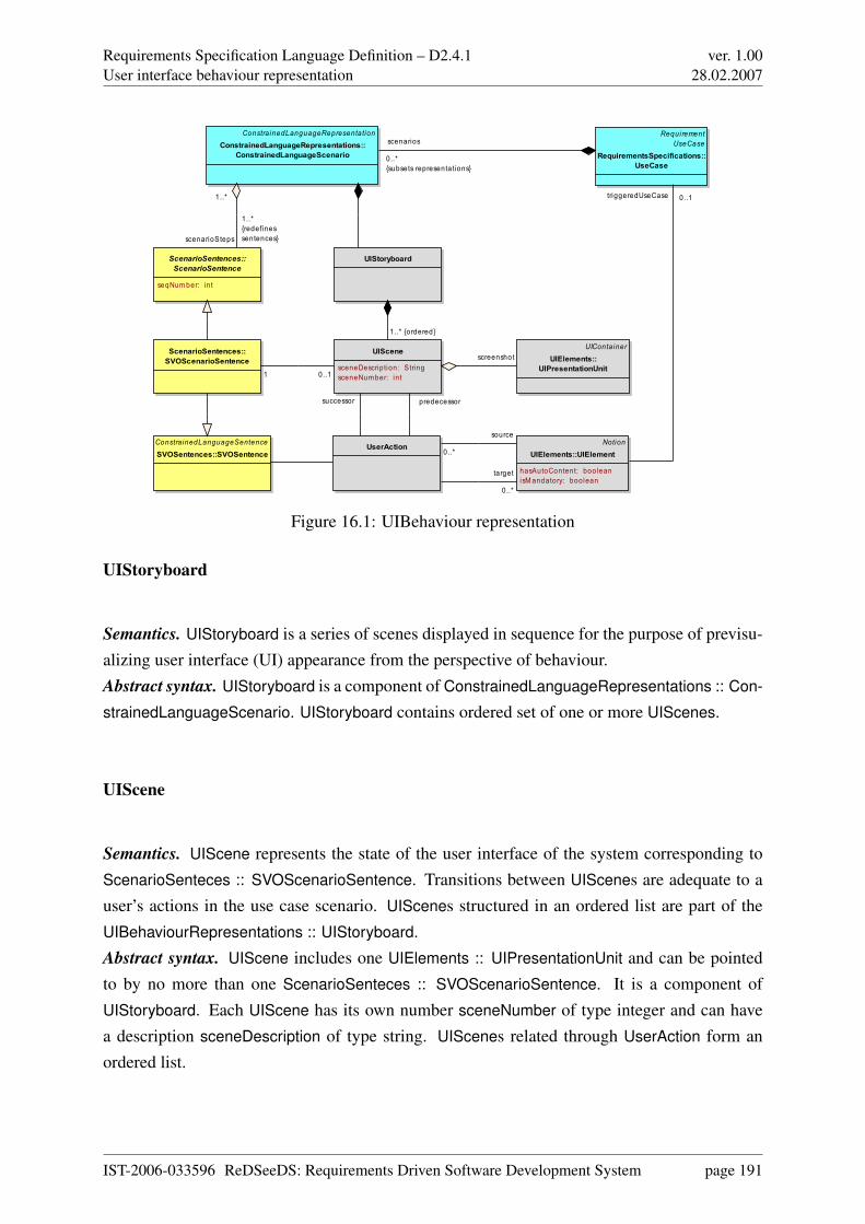
Requirements Specification Language Definition – D2.4.1User interface behaviour representation
ver. 1.0028.02.2007
UIStoryboard
ConstrainedLanguageRepresentationConstrainedLanguageRepresentations::
ConstrainedLanguageScenario
UIScene
sceneDescription: StringsceneNumber: int
ScenarioSentences::ScenarioSentence
seqNum ber: int
ScenarioSentences::SVOScenarioSentence
UserAction NotionUIElements::UIElement
hasAutoContent: booleanisM andatory: boolean
UIContainerUIElements::
UIPresentationUnit
ConstrainedLanguageSentenceSVOSentences::SVOSentence
RequirementUseCase
RequirementsSpecifications::UseCase
1..* {ordered}
scenarioSteps
1..*{redefinessentences}
1..*
successor
1 0..1
predecessor
screenshot
target
0..*
0..*
source
triggeredUseCase 0..1
scenarios
0..*{subsets representations}
Figure 16.1: UIBehaviour representation
UIStoryboard
Semantics. UIStoryboard is a series of scenes displayed in sequence for the purpose of previsu-alizing user interface (UI) appearance from the perspective of behaviour.Abstract syntax. UIStoryboard is a component of ConstrainedLanguageRepresentations :: Con-
strainedLanguageScenario. UIStoryboard contains ordered set of one or more UIScenes.
UIScene
Semantics. UIScene represents the state of the user interface of the system corresponding toScenarioSenteces :: SVOScenarioSentence. Transitions between UIScenes are adequate to auser’s actions in the use case scenario. UIScenes structured in an ordered list are part of theUIBehaviourRepresentations :: UIStoryboard.Abstract syntax. UIScene includes one UIElements :: UIPresentationUnit and can be pointedto by no more than one ScenarioSenteces :: SVOScenarioSentence. It is a component ofUIStoryboard. Each UIScene has its own number sceneNumber of type integer and can havea description sceneDescription of type string. UIScenes related through UserAction form anordered list.
IST-2006-033596 ReDSeeDS: Requirements Driven Software Development System page 191
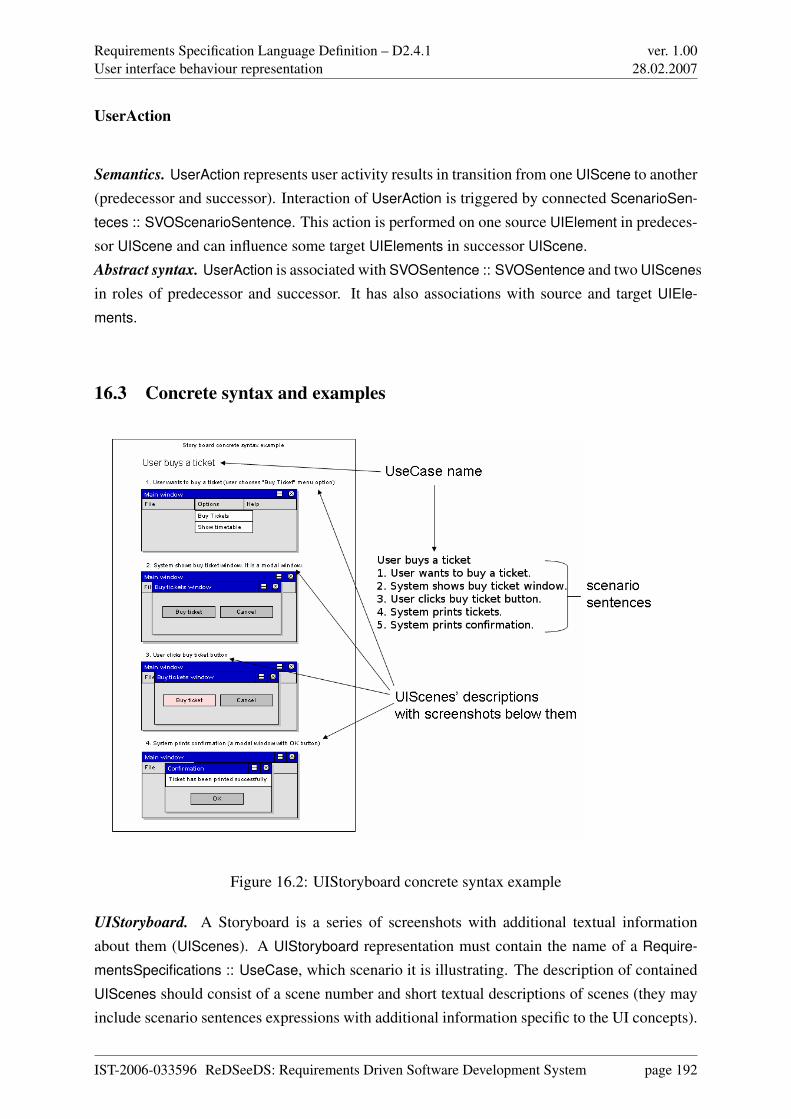
Requirements Specification Language Definition – D2.4.1User interface behaviour representation
ver. 1.0028.02.2007
UserAction
Semantics. UserAction represents user activity results in transition from one UIScene to another(predecessor and successor). Interaction of UserAction is triggered by connected ScenarioSen-
teces :: SVOScenarioSentence. This action is performed on one source UIElement in predeces-sor UIScene and can influence some target UIElements in successor UIScene.Abstract syntax. UserAction is associated with SVOSentence :: SVOSentence and two UIScenesin roles of predecessor and successor. It has also associations with source and target UIEle-
ments.
16.3 Concrete syntax and examples
Figure 16.2: UIStoryboard concrete syntax example
UIStoryboard. A Storyboard is a series of screenshots with additional textual informationabout them (UIScenes). A UIStoryboard representation must contain the name of a Require-
mentsSpecifications :: UseCase, which scenario it is illustrating. The description of containedUIScenes should consist of a scene number and short textual descriptions of scenes (they mayinclude scenario sentences expressions with additional information specific to the UI concepts).
IST-2006-033596 ReDSeeDS: Requirements Driven Software Development System page 192
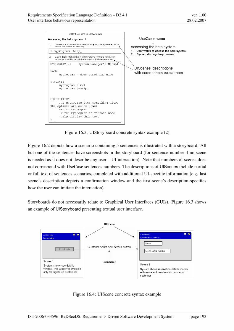
Requirements Specification Language Definition – D2.4.1User interface behaviour representation
ver. 1.0028.02.2007
Figure 16.3: UIStoryboard concrete syntax example (2)
Figure 16.2 depicts how a scenario containing 5 sentences is illustrated with a storyboard. Allbut one of the sentences have screenshots in the storyboard (for sentence number 4 no sceneis needed as it does not describe any user – UI interaction). Note that numbers of scenes doesnot correspond with UseCase sentences numbers. The descriptions of UIScenes include partialor full text of sentences scenarios, completed with additional UI-specific information (e.g. lastscene’s description depicts a confirmation window and the first scene’s description specifieshow the user can initiate the interaction).
Storyboards do not necessarily relate to Graphical User Interfaces (GUIs). Figure 16.3 showsan example of UIStoryboard presenting textual user interface.
Figure 16.4: UIScene concrete syntax example
IST-2006-033596 ReDSeeDS: Requirements Driven Software Development System page 193
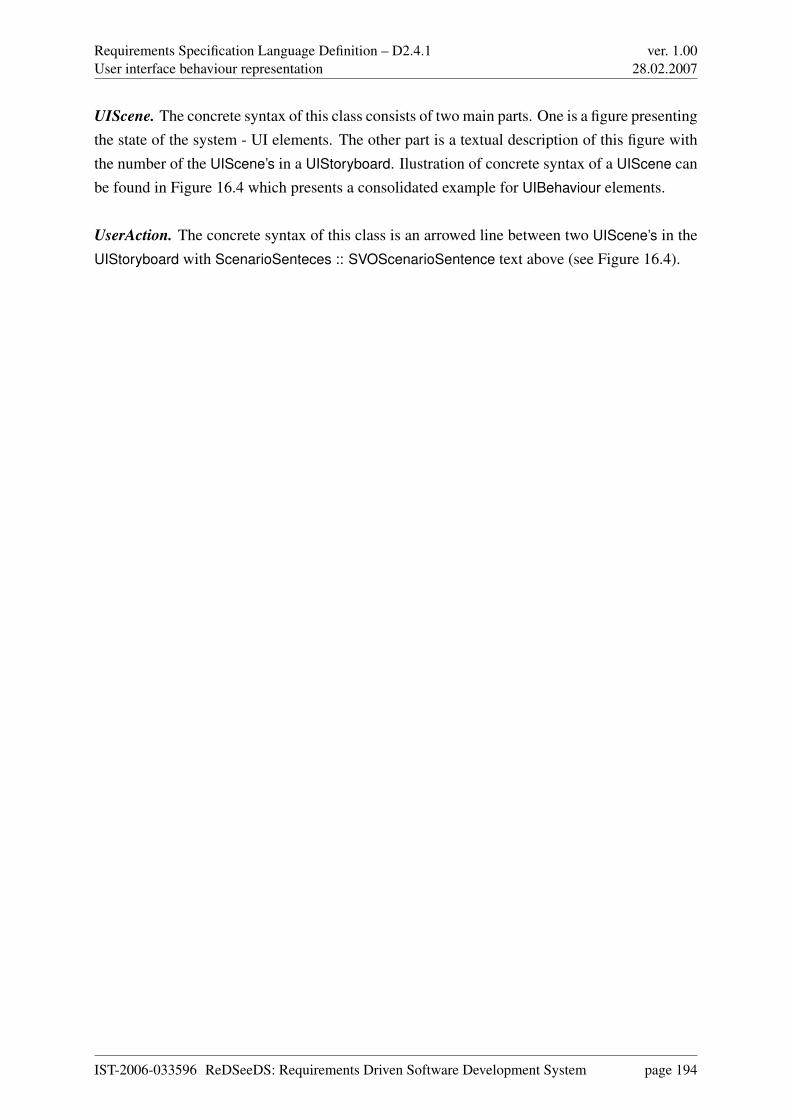
Requirements Specification Language Definition – D2.4.1User interface behaviour representation
ver. 1.0028.02.2007
UIScene. The concrete syntax of this class consists of two main parts. One is a figure presentingthe state of the system - UI elements. The other part is a textual description of this figure withthe number of the UIScene’s in a UIStoryboard. Ilustration of concrete syntax of a UIScene canbe found in Figure 16.4 which presents a consolidated example for UIBehaviour elements.
UserAction. The concrete syntax of this class is an arrowed line between two UIScene’s in theUIStoryboard with ScenarioSenteces :: SVOScenarioSentence text above (see Figure 16.4).
IST-2006-033596 ReDSeeDS: Requirements Driven Software Development System page 194
Requirements Specification Language Definition – D2.4.1Conclusion
ver. 1.0028.02.2007
Chapter 17
Conclusion
This deliverable presents a new requirements specification language named RSL. It integrates abehavioural and a structural part, and even a part for user-interface specifications.
The behavioural part of this language is special because of its clear distinction between Func-tional and Behavioural Requirements as well as its precise definition of their relationships. Itsconceptual definition is new in its clear distinction between requirements and representations
of requirements. This distinction is important for the use of this language as a basis for reusebased on requirements, since only representations can actually be reused. This language isalso unique through its explicit distinction between descriptive and model-based requirementsrepresentations.
The structural part of this language is special because of its explicit inclusion of objects ex-isting in the domain (environment) of the software system to be built — domain objects. Aconceptual Domain Model (to-be) can be represented in newly defined domain entity diagrams.Additionally, descriptions are possible in a newly defined representation of vocabulary, whichis organised as a terminology representation that integrates a dictionary with a thesaurus. Bothkinds of domain representations facilitate a better understanding of the requirements per se.
The part of this language for user-interface specifications is special because of its explicit bind-ing between behavioural representations of requirements (e.g., scenarios in Use Cases) withuser-interface elements. It can be used to describe user interfaces in a platform-independentway. The user interfaces can be textual or graphical, and with various types of access (limited,voice-triggered etc.). Features specific to culture and region are also supported.
IST-2006-033596 ReDSeeDS: Requirements Driven Software Development System page 195
Requirements Specification Language Definition – D2.4.1Conclusion
ver. 1.0028.02.2007
The user-interface specifications may contain textual descriptions as well as screenshots ordrawings illustrating the appearance of user-interface elements. With the envisioned tool sup-port, the graphical representation will allow visualising interaction of a user with a softwaresystem even before any prototype is available.
A major contribution of our work is the coherent integration of all these parts of RSL. In par-ticular, textual descriptions in user-interface specifications can be written according to the samegrammars as the textual descriptions in structural and behavioural specifications.
Our language is the first requirements specification language intimately integrated with UMLand defined using the same metamodelling approach as used for UML itself (using MOF).
This deliverable also presents and explains the complete language definition, from abstractdown to concrete syntax.
IST-2006-033596 ReDSeeDS: Requirements Driven Software Development System page 196
Requirements Specification Language Definition – D2.4.1Profiles for User Interface Representation
ver. 1.0028.02.2007
Appendix A
Profiles for User Interface Representation
This annex describes the predefined standard stereotypes for User Interface Representation. Thestandard stereotypes are specified in two separate profiles. These profiles can be applied to auser model elements just like any other profile.
The stereotypes belonging to the profile are described using a compact tabular form rather thangraphically. The first column gives the name of the stereotype label corresponding to the stereo-type. The actual name of the stereotype is the same as the stereotype label except that the firstletter of each is capitalised. The second column identifies the metaclass to which the stereo-type applies and the third column provides a description of the meaning of the stereotype. Thelast column contains a figure that symbolises redefined concrete syntax of class that stereotypeapplies to.
A.1 Profile for user interface elements
This profile provides concrete syntax for various types of graphical user interface elements ininformation systems. The images are suggestions and they can be changed accordingly. Thefirst two lines are general symbols that can be used to explicitly mark mandatory and critical
IST-2006-033596 ReDSeeDS: Requirements Driven Software Development System page 197
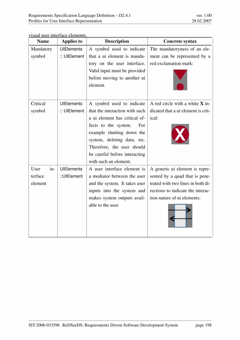
Requirements Specification Language Definition – D2.4.1Profiles for User Interface Representation
ver. 1.0028.02.2007
visual user interface elements.Name Applies to Description Concrete syntax
Mandatorysymbol
UIElements
:: UIElement
A symbol used to indicatethat a ui element is manda-tory on the user interface.Valid input must be providedbefore moving to another uielement.
The mandatoryness of an ele-ment can be represented by ared exclamation mark:
Criticalsymbol
UIElements
:: UIElement
A symbol used to indicatethat the interaction with sucha ui element has critical ef-fects to the system. Forexample shutting down thesystem, deleting data, etc.Therefore, the user shouldbe careful before interactingwith such an element.
A red circle with a white X in-dicated that a ui element is crit-ical:
User in-terfaceelement
UIElements
::UIElement
A user interface element isa mediator between the userand the system. It takes userinputs into the system andmakes system outputs avail-able to the user.
A generic ui element is repre-sented by a quad that is pene-trated with two lines in both di-rections to indicate the interac-tion nature of ui elements:
IST-2006-033596 ReDSeeDS: Requirements Driven Software Development System page 198
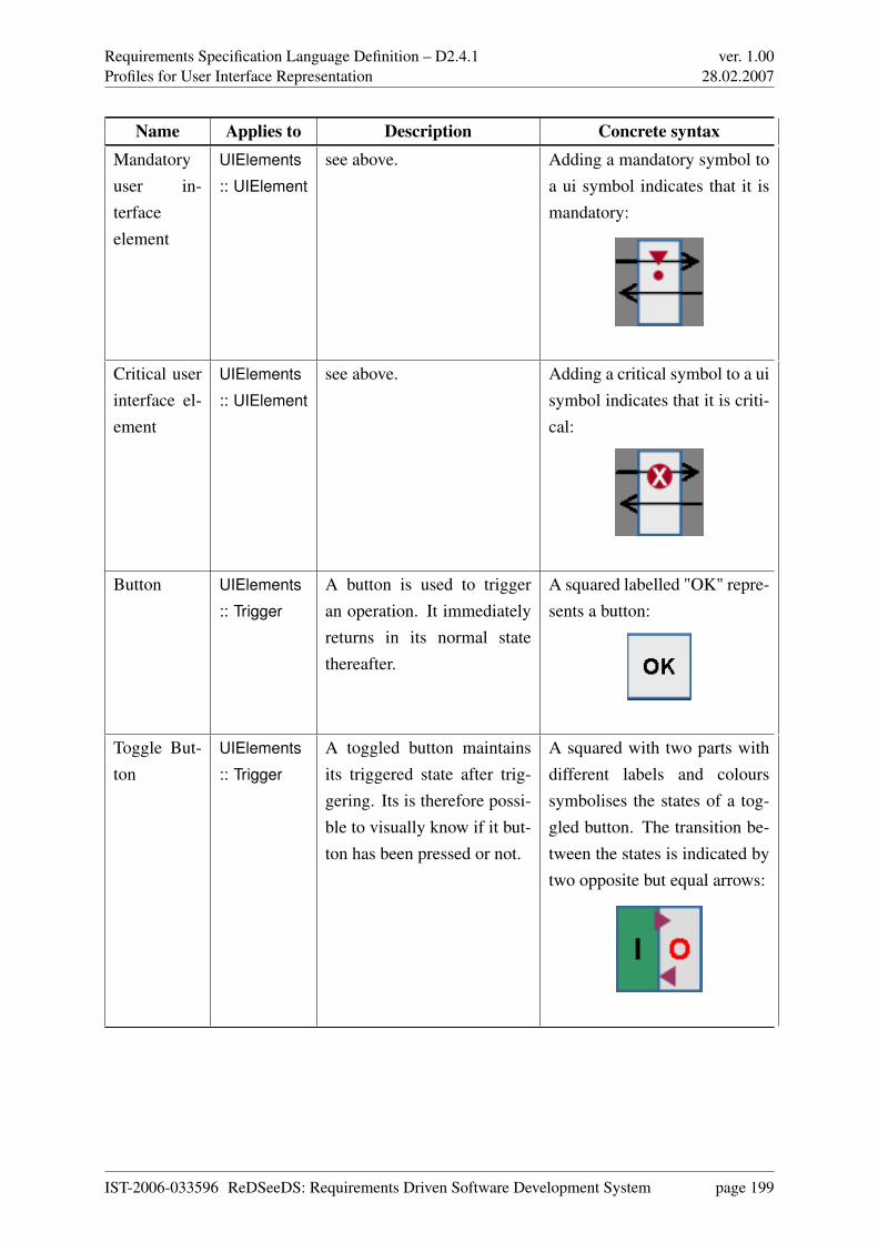
Requirements Specification Language Definition – D2.4.1Profiles for User Interface Representation
ver. 1.0028.02.2007
Name Applies to Description Concrete syntaxMandatoryuser in-terfaceelement
UIElements
:: UIElement
see above. Adding a mandatory symbol toa ui symbol indicates that it ismandatory:
Critical userinterface el-ement
UIElements
:: UIElement
see above. Adding a critical symbol to a uisymbol indicates that it is criti-cal:
Button UIElements
:: Trigger
A button is used to triggeran operation. It immediatelyreturns in its normal statethereafter.
A squared labelled "OK" repre-sents a button:
Toggle But-ton
UIElements
:: Trigger
A toggled button maintainsits triggered state after trig-gering. Its is therefore possi-ble to visually know if it but-ton has been pressed or not.
A squared with two parts withdifferent labels and colourssymbolises the states of a tog-gled button. The transition be-tween the states is indicated bytwo opposite but equal arrows:
IST-2006-033596 ReDSeeDS: Requirements Driven Software Development System page 199
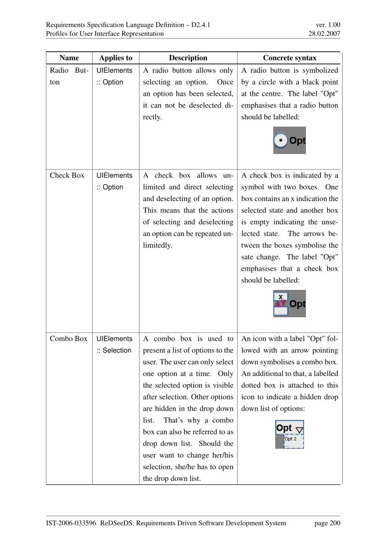
Requirements Specification Language Definition – D2.4.1Profiles for User Interface Representation
ver. 1.0028.02.2007
Name Applies to Description Concrete syntaxRadio But-ton
UIElements
:: Option
A radio button allows onlyselecting an option. Oncean option has been selected,it can not be deselected di-rectly.
A radio button is symbolizedby a circle with a black pointat the centre. The label "Opt"emphasises that a radio buttonshould be labelled:
Check Box UIElements
:: Option
A check box allows un-limited and direct selectingand deselecting of an option.This means that the actionsof selecting and deselectingan option can be repeated un-limitedly.
A check box is indicated by asymbol with two boxes. Onebox contains an x indication theselected state and another boxis empty indicating the unse-lected state. The arrows be-tween the boxes symbolise thesate change. The label "Opt"emphasises that a check boxshould be labelled:
Combo Box UIElements
:: Selection
A combo box is used topresent a list of options to theuser. The user can only selectone option at a time. Onlythe selected option is visibleafter selection. Other optionsare hidden in the drop downlist. That’s why a combobox can also be referred to asdrop down list. Should theuser want to change her/hisselection, she/he has to openthe drop down list.
An icon with a label "Opt" fol-lowed with an arrow pointingdown symbolises a combo box.An additional to that, a labelleddotted box is attached to thisicon to indicate a hidden dropdown list of options:
IST-2006-033596 ReDSeeDS: Requirements Driven Software Development System page 200
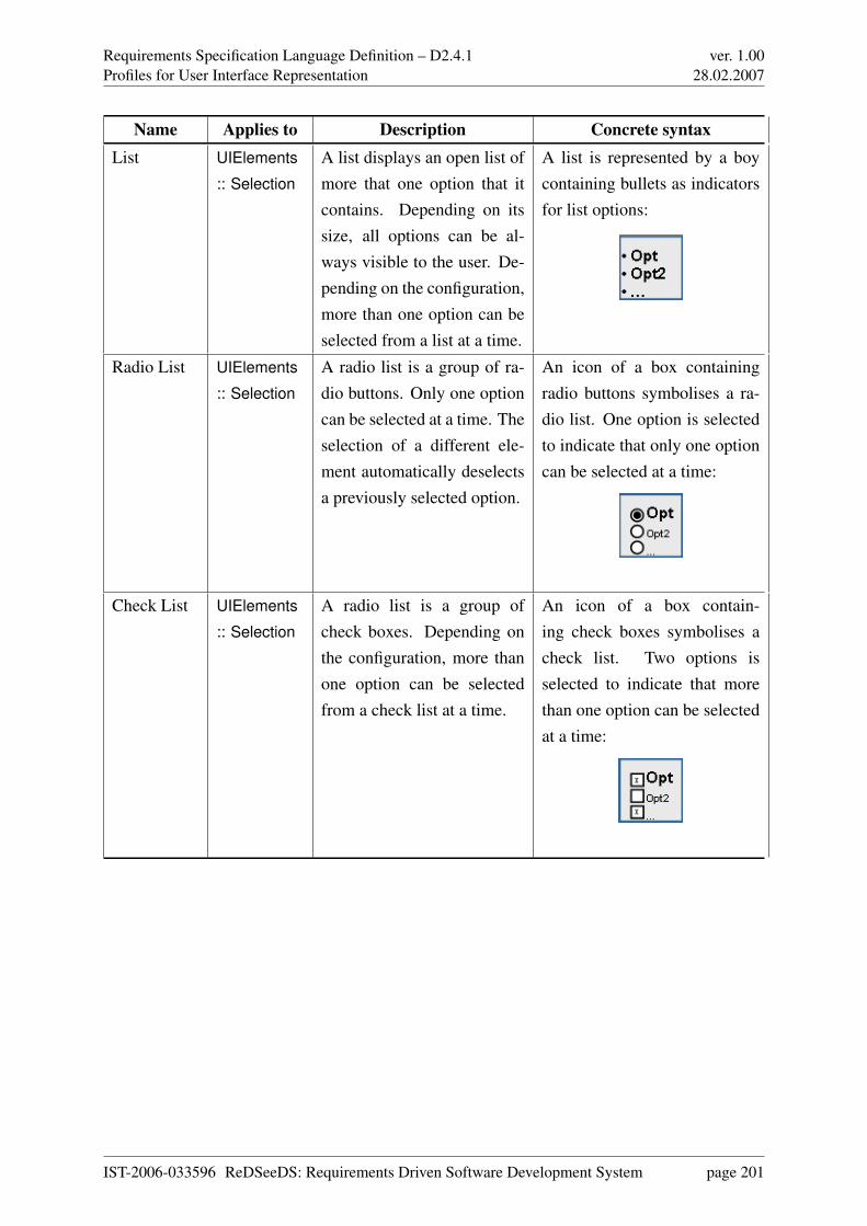
Requirements Specification Language Definition – D2.4.1Profiles for User Interface Representation
ver. 1.0028.02.2007
Name Applies to Description Concrete syntaxList UIElements
:: Selection
A list displays an open list ofmore that one option that itcontains. Depending on itssize, all options can be al-ways visible to the user. De-pending on the configuration,more than one option can beselected from a list at a time.
A list is represented by a boycontaining bullets as indicatorsfor list options:
Radio List UIElements
:: Selection
A radio list is a group of ra-dio buttons. Only one optioncan be selected at a time. Theselection of a different ele-ment automatically deselectsa previously selected option.
An icon of a box containingradio buttons symbolises a ra-dio list. One option is selectedto indicate that only one optioncan be selected at a time:
Check List UIElements
:: Selection
A radio list is a group ofcheck boxes. Depending onthe configuration, more thanone option can be selectedfrom a check list at a time.
An icon of a box contain-ing check boxes symbolises acheck list. Two options isselected to indicate that morethan one option can be selectedat a time:
IST-2006-033596 ReDSeeDS: Requirements Driven Software Development System page 201
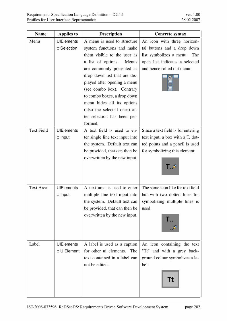
Requirements Specification Language Definition – D2.4.1Profiles for User Interface Representation
ver. 1.0028.02.2007
Name Applies to Description Concrete syntaxMenu UIElements
:: Selection
A menu is used to structuresystem functions and makethem visible to the user asa list of options. Menusare commonly presented asdrop down list that are dis-played after opening a menu(see combo box). Contraryto combo boxes, a drop downmenu hides all its options(also the selected ones) af-ter selection has been per-formed.
An icon with three horizon-tal buttons and a drop downlist symbolizes a menu. Theopen list indicates a selectedand hence rolled out menu:
Text Field UIElements
:: Input
A text field is used to en-ter single line text input intothe system. Default text canbe provided, that can then beoverwritten by the new input.
Since a text field is for enteringtext input, a box with a T, dot-ted points and a pencil is usedfor symbolizing this element:
Text Area UIElements
:: Input
A text area is used to entermultiple line text input intothe system. Default text canbe provided, that can then beoverwritten by the new input.
The same icon like for text fieldbut with two dotted lines forsymbolizing multiple lines isused:
Label UIElements
:: UIElement
A label is used as a captionfor other ui elements. Thetext contained in a label cannot be edited.
An icon containing the text"Tt" and with a grey back-ground colour symbolizes a la-bel:
IST-2006-033596 ReDSeeDS: Requirements Driven Software Development System page 202
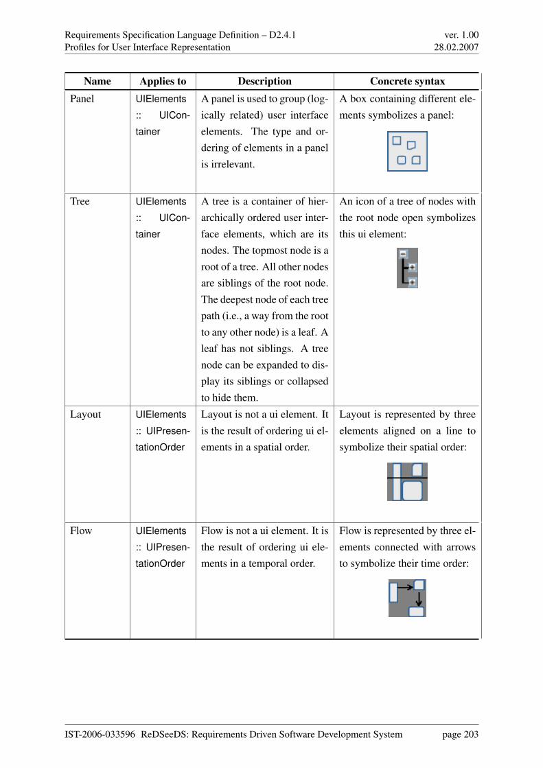
Requirements Specification Language Definition – D2.4.1Profiles for User Interface Representation
ver. 1.0028.02.2007
Name Applies to Description Concrete syntaxPanel UIElements
:: UICon-
tainer
A panel is used to group (log-ically related) user interfaceelements. The type and or-dering of elements in a panelis irrelevant.
A box containing different ele-ments symbolizes a panel:
Tree UIElements
:: UICon-
tainer
A tree is a container of hier-archically ordered user inter-face elements, which are itsnodes. The topmost node is aroot of a tree. All other nodesare siblings of the root node.The deepest node of each treepath (i.e., a way from the rootto any other node) is a leaf. Aleaf has not siblings. A treenode can be expanded to dis-play its siblings or collapsedto hide them.
An icon of a tree of nodes withthe root node open symbolizesthis ui element:
Layout UIElements
:: UIPresen-
tationOrder
Layout is not a ui element. Itis the result of ordering ui el-ements in a spatial order.
Layout is represented by threeelements aligned on a line tosymbolize their spatial order:
Flow UIElements
:: UIPresen-
tationOrder
Flow is not a ui element. It isthe result of ordering ui ele-ments in a temporal order.
Flow is represented by three el-ements connected with arrowsto symbolize their time order:
IST-2006-033596 ReDSeeDS: Requirements Driven Software Development System page 203
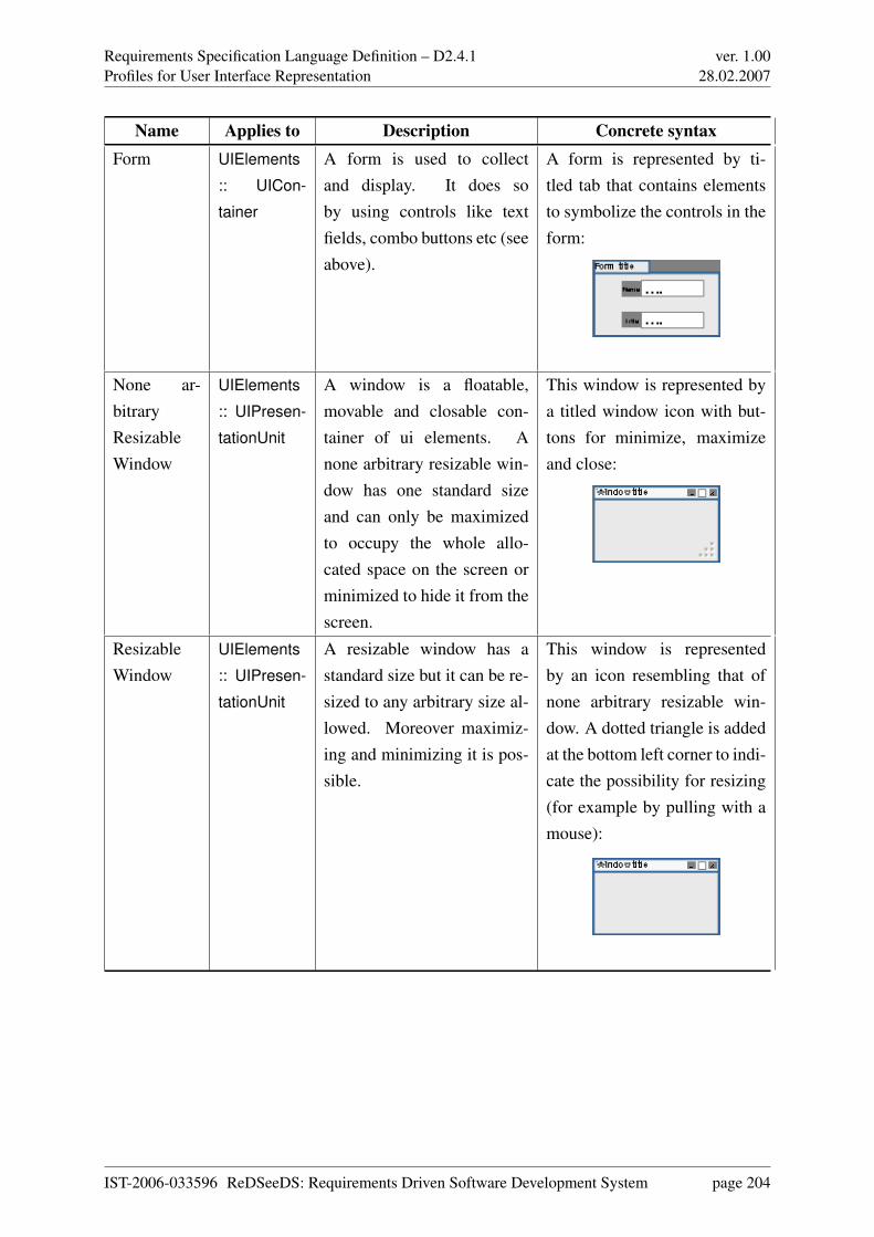
Requirements Specification Language Definition – D2.4.1Profiles for User Interface Representation
ver. 1.0028.02.2007
Name Applies to Description Concrete syntaxForm UIElements
:: UICon-
tainer
A form is used to collectand display. It does soby using controls like textfields, combo buttons etc (seeabove).
A form is represented by ti-tled tab that contains elementsto symbolize the controls in theform:
None ar-bitraryResizableWindow
UIElements
:: UIPresen-
tationUnit
A window is a floatable,movable and closable con-tainer of ui elements. Anone arbitrary resizable win-dow has one standard sizeand can only be maximizedto occupy the whole allo-cated space on the screen orminimized to hide it from thescreen.
This window is represented bya titled window icon with but-tons for minimize, maximizeand close:
ResizableWindow
UIElements
:: UIPresen-
tationUnit
A resizable window has astandard size but it can be re-sized to any arbitrary size al-lowed. Moreover maximiz-ing and minimizing it is pos-sible.
This window is representedby an icon resembling that ofnone arbitrary resizable win-dow. A dotted triangle is addedat the bottom left corner to indi-cate the possibility for resizing(for example by pulling with amouse):
IST-2006-033596 ReDSeeDS: Requirements Driven Software Development System page 204
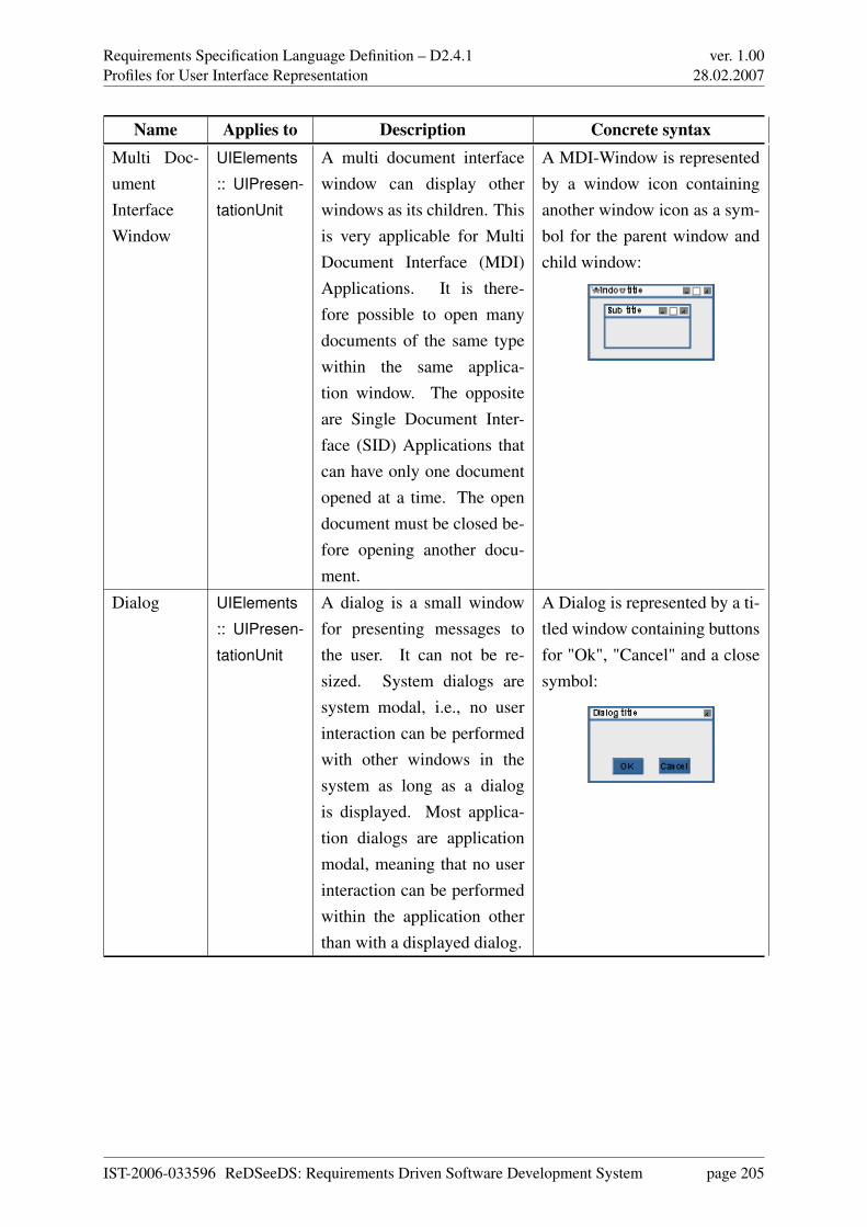
Requirements Specification Language Definition – D2.4.1Profiles for User Interface Representation
ver. 1.0028.02.2007
Name Applies to Description Concrete syntaxMulti Doc-umentInterfaceWindow
UIElements
:: UIPresen-
tationUnit
A multi document interfacewindow can display otherwindows as its children. Thisis very applicable for MultiDocument Interface (MDI)Applications. It is there-fore possible to open manydocuments of the same typewithin the same applica-tion window. The oppositeare Single Document Inter-face (SID) Applications thatcan have only one documentopened at a time. The opendocument must be closed be-fore opening another docu-ment.
A MDI-Window is representedby a window icon containinganother window icon as a sym-bol for the parent window andchild window:
Dialog UIElements
:: UIPresen-
tationUnit
A dialog is a small windowfor presenting messages tothe user. It can not be re-sized. System dialogs aresystem modal, i.e., no userinteraction can be performedwith other windows in thesystem as long as a dialogis displayed. Most applica-tion dialogs are applicationmodal, meaning that no userinteraction can be performedwithin the application otherthan with a displayed dialog.
A Dialog is represented by a ti-tled window containing buttonsfor "Ok", "Cancel" and a closesymbol:
IST-2006-033596 ReDSeeDS: Requirements Driven Software Development System page 205
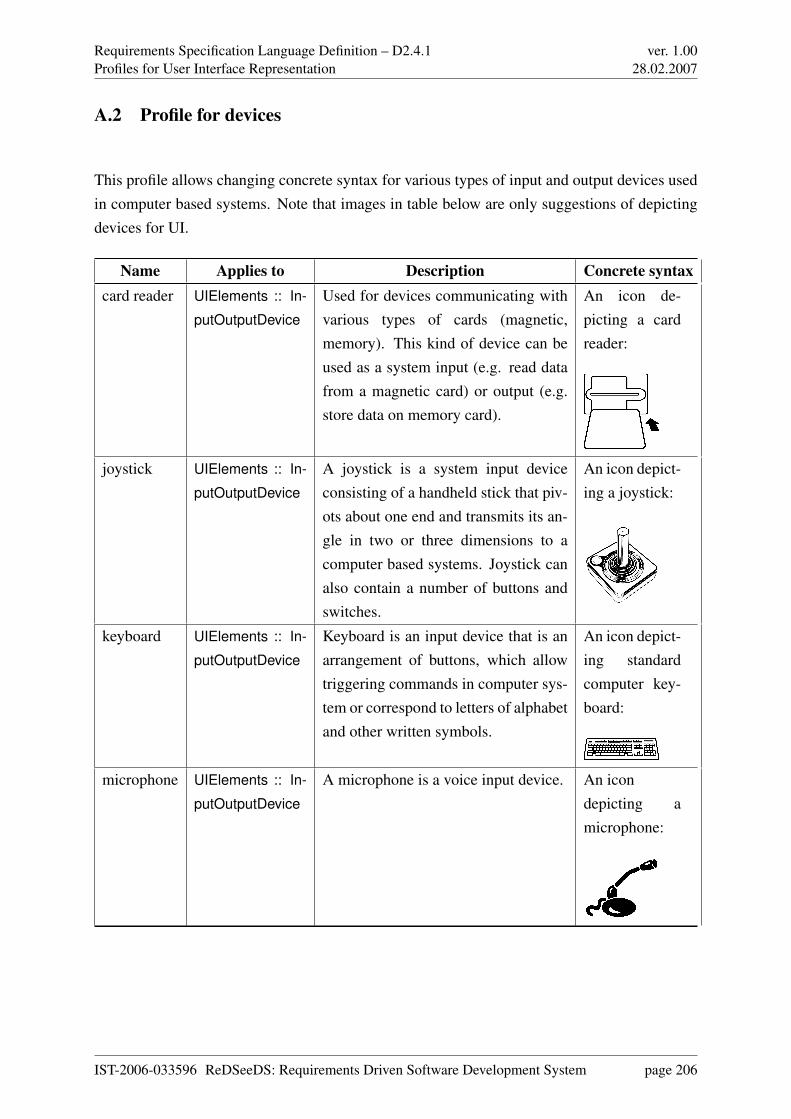
Requirements Specification Language Definition – D2.4.1Profiles for User Interface Representation
ver. 1.0028.02.2007
A.2 Profile for devices
This profile allows changing concrete syntax for various types of input and output devices usedin computer based systems. Note that images in table below are only suggestions of depictingdevices for UI.
Name Applies to Description Concrete syntaxcard reader UIElements :: In-
putOutputDevice
Used for devices communicating withvarious types of cards (magnetic,memory). This kind of device can beused as a system input (e.g. read datafrom a magnetic card) or output (e.g.store data on memory card).
An icon de-picting a cardreader:
joystick UIElements :: In-
putOutputDevice
A joystick is a system input deviceconsisting of a handheld stick that piv-ots about one end and transmits its an-gle in two or three dimensions to acomputer based systems. Joystick canalso contain a number of buttons andswitches.
An icon depict-ing a joystick:
keyboard UIElements :: In-
putOutputDevice
Keyboard is an input device that is anarrangement of buttons, which allowtriggering commands in computer sys-tem or correspond to letters of alphabetand other written symbols.
An icon depict-ing standardcomputer key-board:
microphone UIElements :: In-
putOutputDevice
A microphone is a voice input device. An icondepicting amicrophone:
IST-2006-033596 ReDSeeDS: Requirements Driven Software Development System page 206
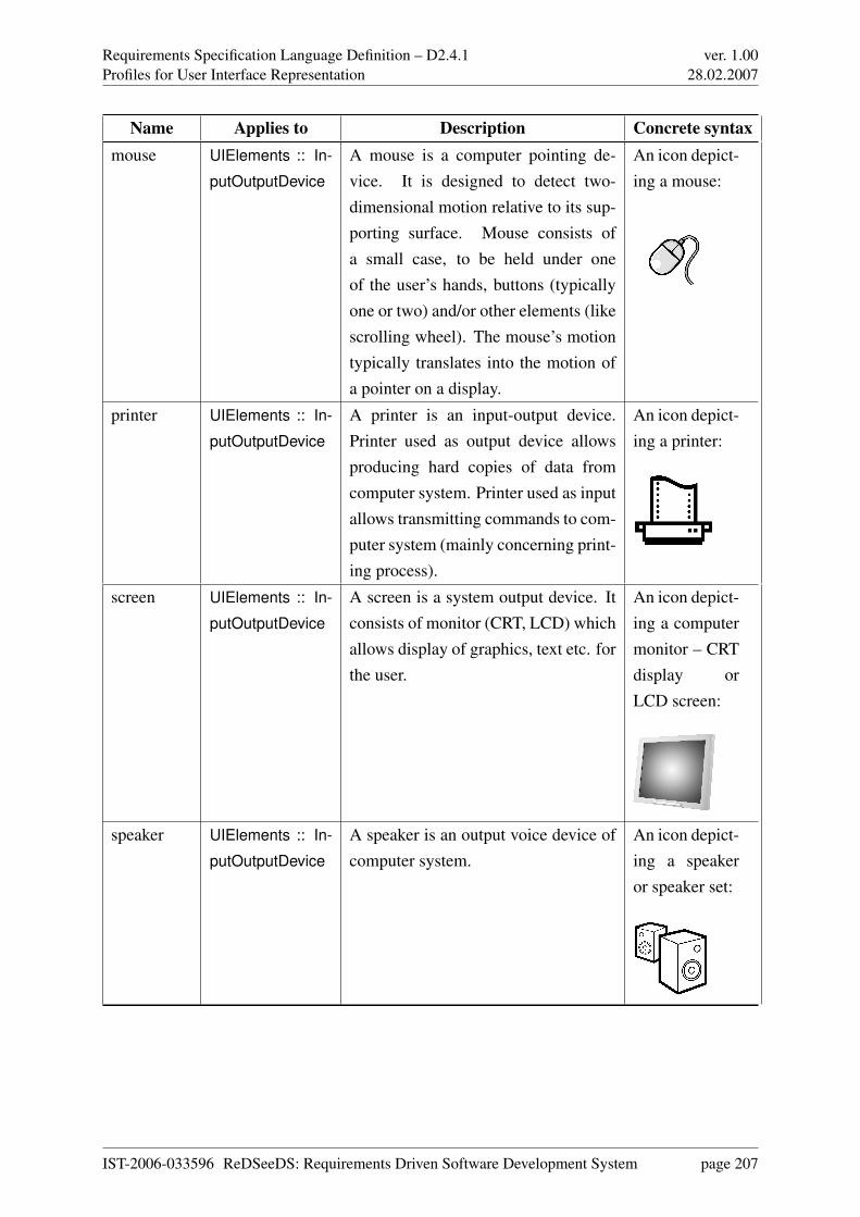
Requirements Specification Language Definition – D2.4.1Profiles for User Interface Representation
ver. 1.0028.02.2007
Name Applies to Description Concrete syntaxmouse UIElements :: In-
putOutputDevice
A mouse is a computer pointing de-vice. It is designed to detect two-dimensional motion relative to its sup-porting surface. Mouse consists ofa small case, to be held under oneof the user’s hands, buttons (typicallyone or two) and/or other elements (likescrolling wheel). The mouse’s motiontypically translates into the motion ofa pointer on a display.
An icon depict-ing a mouse:
printer UIElements :: In-
putOutputDevice
A printer is an input-output device.Printer used as output device allowsproducing hard copies of data fromcomputer system. Printer used as inputallows transmitting commands to com-puter system (mainly concerning print-ing process).
An icon depict-ing a printer:
screen UIElements :: In-
putOutputDevice
A screen is a system output device. Itconsists of monitor (CRT, LCD) whichallows display of graphics, text etc. forthe user.
An icon depict-ing a computermonitor – CRTdisplay orLCD screen:
speaker UIElements :: In-
putOutputDevice
A speaker is an output voice device ofcomputer system.
An icon depict-ing a speakeror speaker set:
IST-2006-033596 ReDSeeDS: Requirements Driven Software Development System page 207
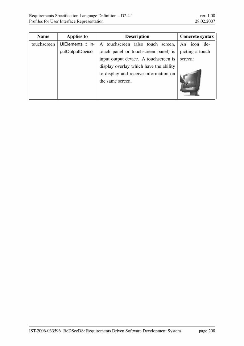
Requirements Specification Language Definition – D2.4.1Profiles for User Interface Representation
ver. 1.0028.02.2007
Name Applies to Description Concrete syntaxtouchscreen UIElements :: In-
putOutputDevice
A touchscreen (also touch screen,touch panel or touchscreen panel) isinput output device. A touchscreen isdisplay overlay which have the abilityto display and receive information onthe same screen.
An icon de-picting a touchscreen:
IST-2006-033596 ReDSeeDS: Requirements Driven Software Development System page 208
Requirements Specification Language Definition – D2.4.1List of abbreviations
ver. 1.0028.02.2007
Appendix B
List of abbreviations
ACE Attempto Controlled EnglishAIO Abstract Interaction ObjectsATM Automatic Teller MachineCASE Computer Aided Software EngineeringCBS Computer-Based SystemCHI Computer Human InteractionCIO Concrete Interaction ObjectsDM Domain ModelGUI Graphical User InterfaceIEEE Institute of Electrical and Electronics EngineersINTERACT International Conference on Human Computer InteractionIUI International Conference on Intelligent User InterfacesMB-UID Model Based User Interface DevelopmentMOF Meta Object FacilityOMG Object Management GroupOOA Object Oriented AnalysesRE Requirements EngineeringRSL Requirements Specification LanguageRUP Rational Unified ProcessSVO Subject Verb ObjectSysML System Modelling LanguageTORE Task and Object Oriented Requirements Engineering
IST-2006-033596 ReDSeeDS: Requirements Driven Software Development System page 209
Requirements Specification Language Definition – D2.4.1List of abbreviations
ver. 1.0028.02.2007
UbiComp International Conference on Ubiquitous ComputingUC Use CaseUI User InterfaceUIDL User Interface Description LanguageUML Unified Modeling LanguageXML Extensible Markup LanguageXUL XML User Interface Language
IST-2006-033596 ReDSeeDS: Requirements Driven Software Development System page 210
Requirements Specification Language Definition – D2.4.1Bibliography
ver. 1.0028.02.2007
Bibliography
[AH02] M Abrams and J Helms. UIML v3.0 Draft Specification, 2002.
[Ant96] Annie I. Antón. Goal-based requirements analysis. In ICRE ’96: Proceedings of
the 2nd International Conference on Requirements Engineering (ICRE ’96), page136, Washington, DC, USA, 1996. IEEE Computer Society.
[BI96] Barry Boehm and Hoh In. Identifying quality-requirement conflicts. IEEE Soft-
ware, 13(2):25–35, 1996.
[BMT90] Richard Beckwith, George A Miller, and Randee Tengi. Design and implementa-tion of the wordnet lexical database and searching software. International Journal
on Lexicography, 3(4):62–77, 1990.
[BPG+01] Paolo Bresciani, Anna Perini, Paolo Giorgini, Fausto Giunchiglia, and John My-lopoulos. Modeling early requirements in tropos: A transformation based ap-proach. In AOSE, pages 151–168, 2001.
[Bro03] Der Brockhaus Computer und Informationstechnologie. Brockhaus, Mannheim,2003.
[CdPL04] Luiz Marcio Cysneiros and Julio Cesar Sampaio do Prado Leite. Nonfunctional re-quirements: from elicitation to conceptual models. IEEE Transactions on Software
Engineering, 30(5):328–350, May 2004.
[CEE+04] Kai-Uwe Carstensen, Christian Ebert, Cornelia Endriss, Susanne Jekat, and RalfKlabunde, editors. Computerlinguistik und Sprachtechnologie. Elsevier SpektrumAkademischer Verlag, 2004.
[CKM01] Jaelson Castro, Manuel Kolp, and John Mylopoulos. A requirements-driven devel-opment methodology. Lecture Notes in Computer Science, 2068, 2001.
[CKM02] Jaelson Castro, Manuel Kolp, and John Mylopoulos. Towards requirements-driveninformation systems engineering: The tropos project. To Appear in Information
Systems, Elsevier, Amsterdam, The Netherlands, 2002.
IST-2006-033596 ReDSeeDS: Requirements Driven Software Development System page 211
Requirements Specification Language Definition – D2.4.1Bibliography
ver. 1.0028.02.2007
[Coc97] Alistair Cockburn. Structuring use cases with goals. Journal of Object-Oriented
Programming, 5(10):56–62, 1997.
[Coc00] Alistair Cockburn. Writing Effective Use Cases. Addison-Wesley, 2000.
[DvLF93] A. Dardenne, A. van Lamsweerde, and S. Fickas. Goal-directed requirements ac-quisition. Science of Computer Programming, 20:3–50, 1993.
[EK02] Gerald Ebner and Hermann Kaindl. Tracing all around in reengineering. IEEE
Software, 19(3):70–77, 2002.
[FHK+05] Norbert E. Fuchs, Stefan Höfler, Kaarel Kaljurand, Fabio Rinaldi, and GeroldSchneider. Attempto controlled english: A knowledge representation languagereadable by humans and machines. Lecture Notes in Computer Science, 3564,2005.
[Fow04] Martin Fowler. UML Distilled: A Brief Guide to the Standard Object Modeling
Language, Third Edition. Addison-Wesley, 2004.
[Gli05] Martin Glinz. Rethinking the notion of non-functional requirements. In Proceed-
ings of the Third World Congress for Software Quality, Munich, Germany. Depart-ment of Informatics, University of Zurich, September 2005.
[GM90] Derek Gross and Katherine J. Miller. Adjectives in wordnet. International Journal
on Lexicography, 3(4):265–277, 1990.
[GMP01] Fausto Giunchiglia, John Mylopoulos, and Anna Perini. The tropos software de-velopment methodology. Technical Report No. 0111-20, ITC - IRST. Submitted to
AAMAS ’02. A Knowledge Level Software Engineering 15, 2001.
[GPM+01] Paolo Giorgini, Anna Perini, John Mylopoulos, Fausto Giunchiglia, and PaoloBresciani. Agent-oriented software development: A case study. In Proceedings
of the Thirteenth International Conference on Software Engineering & Knowledge
Engineering (SEKE01), 2001.
[GPS01] Fausto Giunchiglia, Anna Perini, and Fabrizio Sannicolo. Knowledge level soft-ware engineering. In Springer Verlag, Editor, In Proceedings of ATAL 2001, Seattle,
USA. Also IRST TR 011222, Istituto Trentino Di Cultura, Trento, Italy, 2001.
[Hoe04] Stefan Hoefler. The syntax of attempto controlled english: An abstract grammar forace 4.0, technical report. Technical Report ifi-2004.03, Department of Informatics,University of Zurich, 2004.
[Kai93] H. Kaindl. The missing link in requirements engineering. ACM Software Engineer-
ing Notes (SEN), 18(2):30–39, 1993.
IST-2006-033596 ReDSeeDS: Requirements Driven Software Development System page 212
Requirements Specification Language Definition – D2.4.1Bibliography
ver. 1.0028.02.2007
[Kai95] H. Kaindl. An integration of scenarios with their purposes in task modeling. InProceedings of the Symposium on Designing Interactive Systems: Processes, Prac-
tices, Methods, & Techniques (DIS ’95), pages 227–235, Ann Arbor, MI, August1995. ACM.
[Kai96] H. Kaindl. Using hypertext for semiformal representation in requirements engi-neering practice. The New Review of Hypermedia and Multimedia, 2:149–173,1996.
[Kai97] H. Kaindl. A practical approach to combining requirements definition and object-oriented analysis. Annals of Software Engineering, 3:319–343, 1997.
[Kai00] H. Kaindl. A design process based on a model combining scenarios with goals andfunctions. IEEE Transactions on Systems, Man, and Cybernetics (SMC) Part A,30(5):537–551, Sept. 2000.
[Kai05] Hermann Kaindl. A scenario-based approach for requirements engineering: Expe-rience in a telecommunication software development project. Systems Engineering,8(3):197–209, 2005.
[KGM02] Manuel Kolp, Paolo Giorgini, and John Mylopoulos. A goal-based organizationalperspective on multi-agent architectures. In ATAL ’01: Revised Papers from the 8th
International Workshop on Intelligent Agents VIII, LNCS 2333, pages 128–140.Springer, 2002.
[Kru03] Philippe Kruchten. The Rational Unified Process: An Introduction, 3rd ed. AddisonWesley, 2003.
[KS91] H. Kaindl and M. Snaprud. Hypertext and structured object representation: A uni-fying view. In Proceedings of the Third ACM Conference on Hypertext (Hypertext
’91), pages 345–358, San Antonio, TX, December 1991.
[Kur04] Dominik Kuropka. Modelle zur Repräsentation natürlichsprachlicher Dokumente.Logos Verlag Berlin, 2004.
[Lar04] Craig Larman. Applying UML and Patterns: An Introduction to Object-Oriented
Analysis and Design and Iterative Development. Prentice Hall, Englewood Cliffs,NJ, second edition, 2004.
[Lau02] Søren Lauesen. Software Requirements: Styles and Techniques. Addison-Wesley,Reading, MA, 2002.
[Lau05] Soren Lauesen. User Interface Design: A Software Engineering Perspective. Ad-dison Wesley, 2005.
IST-2006-033596 ReDSeeDS: Requirements Driven Software Development System page 213
Requirements Specification Language Definition – D2.4.1Bibliography
ver. 1.0028.02.2007
[Lim04] Q Limbourg. Multi-Path Development of User Interfaces. PhD thesis, Universitécatholique de Louvain, Louvain, 2004.
[MBF+90] George A Miller, Richard Beckwith, Christiane Fellbaum, Derek Gross, andKatherine J Miller. Introduction to wordnet: An on-line lexical database. Inter-
national Journal of Lexicography, 3(4):235–244, 1990.
[MC00] John Mylopoulos and Jaelson Castro. Tropos: A framework for requirements-driven software development. In J. Brinkkemper and A. Solvberg, Editors, Informa-
tion Systems Engineering: State of the Art and Research Themes. SpringerVerlag,2000.
[MCL+01] John Mylopoulos, Lawrence Chung, Stephen Liao, Huaiqing Wang, and Eric Yu.Exploring alternatives during requirements analysis. IEEE Software, 18(1):92–96,/2001.
[MCY99] John Mylopoulos, Lawrence Chung, and Eric Yu. From object-oriented to goal-oriented requirements analysis. Communications of the ACM, 42(1):31–37, 1999.
[Mil90] George A. Miller. Nouns in wordnet: a lexical inheritance system. International
Journal of Lexicography, 3(4):245–264, 1990.
[MKC01] John Mylopoulos, Manuel Kolp, and Jaelson Castro. UML for agent-oriented soft-ware development: The tropos proposal. In UML 2001 - The Unified Modeling
Language.Modeling Languages, Concepts, and Tools: Fourth International Con-
ference, LNCS 2185, pages 422–441. Springer, 2001.
[MKG02] John Mylopoulos, Manuel Kolp, and Paolo Giorgini. Agent-oriented software de-velopment. In Methods and Applications of Artificial Intelligence: Second Hellenic
Conference on AI, SETN, LNCS 2308, pages 3–17. Springer, 2002.
[MM03] Joaquin Miller and Jishnu Mukerji, editors. MDA Guide Version 1.0.1, omg/03-06-
01. Object Management Group, 2003.
[Mol04] P. Molina. A review to model-based user interface development technolgy. In Pro-
ceedings of the first Workshop on Making Model-Based User Interfaces Practical,2004.
[MOW01] Pierre Metz, John O’Brien, and Wolfgang Weber. Against use case interleaving.Lecture Notes in Computer Science, 2185:472–486, 2001.
[Moz02] Mozilla. XUL Programmer’s Reference, 2002.
IST-2006-033596 ReDSeeDS: Requirements Driven Software Development System page 214
Requirements Specification Language Definition – D2.4.1Bibliography
ver. 1.0028.02.2007
[Muk06] Kizito S Mukasa. Model-Based Generation of User Interface Prototypes - A De-
sign Tool for the formal Description of generic and consistent User Interfaces with
XML. PhD thesis, Kaiserslautern University of Technology, Kaiserslautern, Ger-many, 2006.
[Obj03a] Object Management Group. Meta Object Facility (MOF) 2.0 Core Specification,
Final Adopted Specification, ptc/03-10-04, 2003.
[Obj03b] Object Management Group. OCL 2.0, Final Adopted Specification, ptc/03-10-14,2003.
[Obj05a] Object Management Group. Unified Modeling Language: Infrastructure, version
2.0, formal/05-07-05, 2005.
[Obj05b] Object Management Group. Unified Modeling Language: Superstructure, version
2.0, formal/05-07-04, 2005.
[Obj06a] Object Management Group. Meta Object Facility Core Specification, version 2.0,
formal/2006-01-01, 2006.
[Obj06b] Object Management Group. Systems Modeling Language (SysML) Specification,
version 1.0, ptc/2006-05-03, 2006.
[PK03] B Paech and K Kohler. Task-driven requirements in object-oriented development.volume 753 of The International Series in Engineering and Computer Science,chapter 3, pages 45–68. Springer, 2003.
[SBNS05a] Michał Smiałek, Jacek Bojarski, Wiktor Nowakowski, and Tomasz Straszak. Sce-nario construction tool based on extended UML metamodel. Lecture Notes in Com-
puter Science, 3713:414–429, 2005.
[SBNS05b] Michał Smiałek, Jacek Bojarski, Wiktor Nowakowski, and Tomasz Straszak. Writ-ing coherent user stories with tool support. Lecture Notes in Computer Science,3556:247–250, 2005.
[Sim99] A J H Simons. Use cases considered harmful. In Proceedings of the 29th Con-
ference on Technology of Object-Oriented Languages and Systems-TOOLS Eu-
rope’99, pages 194–203, Nancy, France, June 1999. IEEE Computer Society Press.
[SK94] M. Snaprud and H. Kaindl. Types and inheritance in hypertext. International Jour-
nal of Human-Computer Studies (IJHCS), 41(1/2):223–241, July/August 1994.
[Sze96] Pedro Szekely. Retrospective and challenges for model-based interface develop-ment. Design, Specification and Verification of Interactive Systems., 1996.
IST-2006-033596 ReDSeeDS: Requirements Driven Software Development System page 215
Requirements Specification Language Definition – D2.4.1Bibliography
ver. 1.0028.02.2007
[vLL00] Axel van Lamsweerde and Emmanuel Letier. Handling obstacles in goal-oriented requirements engineering. IEEE Transactions on Software Engineering,26(10):978–1005, 2000.
[VPG99] Piek Vossen, Wim Peters, and Julio Gonzalo. Towards a universal index of mean-ing. In Proceedings of SIGLEX (Special Interest Group on the Lexicon), 1999.
[ZK99] D. Zuehlke and L. Krauss. Human adapted design of machines and process user
interfaces based on WINDOWS. Shaker, 1999.
IST-2006-033596 ReDSeeDS: Requirements Driven Software Development System page 216