standard specification for annular ball bearings for...
TRANSCRIPT

Designation: F2332 − 06
Standard Specification forAnnular Ball Bearings for Instruments and PrecisionRotating Components1
This standard is issued under the fixed designation F2332; the number immediately following the designation indicates the year oforiginal adoption or, in the case of revision, the year of last revision. A number in parentheses indicates the year of last reapproval. Asuperscript epsilon (´) indicates an editorial change since the last revision or reapproval.
1. Scope
1.1 This specification covers annular ball bearings intendedprimarily for use in instrument and precision rotating compo-nents. Instrument and precision ball bearings should meettolerances specified in ABMA Standard 12.2, Instrument BallBearings Inch Design for Classes ABEC 5P and 7P.
1.2 Intended Use—Ball bearings defined by this specifica-tion are intended for use in critical components of instrumentsystems. Such components range from air circulating blowersand drive motors through precision gear trains, gyro gimbals,and pickoffs to rate integrating spin-motors.
1.3 The specification contains many of the requirements ofMIL-B-81793, which was originally developed by the Depart-ment of Defense and maintained by the Naval Air SystemsCommand (Navy-AS) in Lakehurst, NJ. The following gov-ernment activity codes may be found in the Department ofDefense, Standardization Directory SD-1.2
Preparing activity Custodians Review activitiesNavy - AS Army - AT Army-AV
Navy - AS Navy - MC, SHAir Force - 99 Air Force–84DLA - GS
1.4 Classification—Annular ball bearings for instrumentand precision rotating components shall be of the followingtypes, as specified:
1.4.1 Type I—Annular ball bearing, for instruments andprecision rotating components, deep groove, unflanged; (SeeAnnex A1-Annex A4)
1.4.2 Type II—Annular ball bearing, for instruments andprecision rotating components, deep groove, flanged; (SeeAnnex A5-Annex A8)
1.4.3 Type III—Annular ball bearing, for instruments andprecision rotating components, deep groove, unflanged, innerring extended; (See Annex A9-Annex A12)
1.4.4 Type IV—Annular ball bearing, for instruments andprecision rotating components, deep groove, flanged, inner ringextended; (See Annex A13-Annex A16)
1.4.5 Type V—Annular ball bearing, for instruments andprecision rotating components, angular contact, unflanged,nonseparable, and counterbored outer ring; (See AnnexA17-Annex A20)
1.4.6 Type VI—Annular ball bearing, for instruments andprecision rotating components, angular contact, flanged, non-separable, and counterbored outer ring on flange side; (SeeAnnex A21-Annex A24)
1.4.7 Type VII—Annular ball bearing, for instruments andprecision rotating components, angular contact, unflanged,separable, and stepped inner ring; (See Annex A25-AnnexA28)
1.4.8 Type VIII—Annular ball bearing, for instruments andprecision rotating components, angular contact, flanged, sepa-rable, and stepped inner ring; (See Annex A29-Annex A32)
1.4.9 Type IX—Annular ball bearing, for instruments andprecision rotating components, angular contact, unflanged,nonseparable, and stepped inner ring. (See Annex A33-AnnexA36)
1.5 Inch-Pound Specification—This specification coversonly the inch-pound bearings.
1.6 This standard does not purport to address all of thesafety concerns, if any, associated with its use. It is theresponsibility of the user of this standard to establish appro-priate safety and health practices and determine the applica-bility of regulatory requirements prior to use.
2. Referenced Documents
2.1 ASTM Standards:3
A240/A240M Specification for Chromium and Chromium-Nickel Stainless Steel Plate, Sheet, and Strip for PressureVessels and for General Applications
A313/A313M Specification for Stainless Steel Spring WireA380 Practice for Cleaning, Descaling, and Passivation of
1 This specification is under the jurisdiction of ASTM Committee F34 on RollingElement Bearings and is the direct responsibility of Subcommittee F34.06 onAerospace.
Current edition approved Nov. 1, 2006. Published February 2007. DOI: 10.1520/F2332-06.
2 The military codes that are listed in SD-1 give the address and phone numbersof the DoD contacts. These are found in the DoD’s ASSIST website http://assist.daps.dla.mil/.
3 For referenced ASTM standards, visit the ASTM website, www.astm.org, orcontact ASTM Customer Service at [email protected]. For Annual Book of ASTMStandards volume information, refer to the standard’s Document Summary page onthe ASTM website.
Copyright © ASTM International, 100 Barr Harbor Drive, PO Box C700, West Conshohocken, PA 19428-2959. United States
1Copyright by ASTM Int'l (all rights reserved);

Stainless Steel Parts, Equipment, and SystemsA580/A580M Specification for Stainless Steel WireA666 Specification for Annealed or Cold-Worked Austenitic
Stainless Steel Sheet, Strip, Plate, and Flat BarA756 Specification for Stainless Anti-Friction Bearing SteelA967 Specification for Chemical Passivation Treatments for
Stainless Steel PartsD2273 Test Method for Trace Sediment in Lubricating OilsE45 Test Methods for Determining the Inclusion Content of
SteelE140 Hardness Conversion Tables for Metals Relationship
Among Brinell Hardness, Vickers Hardness, RockwellHardness, Superficial Hardness, Knoop Hardness, andScleroscope Hardness
2.2 ABMA Standards:4
STD 1 Terminology for Anti-Friction Ball and Roller Bear-ings and Parts
STD 10 Metal BallsSTD 12.2 Instruments Ball Bearings—Inch Design2.3 SAE-AMS Specifications:5
SAE-AMS 2303 Aircraft Quality Steel Cleanliness, Marten-sitic Corrosion Resistant Steels, Magnetic Particle Inspec-tion Procedure
SAE-AMS 5688 Steel, Corrosion Resistant Wire, 18CR-9.0NI, (SAE 30302), Spring Temper
SAE-AMS 5880 Steel, Corrosion Resistant Bars, Wire andForgings, 17CR-0.52MO (0.95-1.2C)
SAE-AMS 6444 Steel Bars, Forgings, and Mechanical Tub-ing, 1.45 Cr (0.98-1.10C) (SAE 52100) Premium AircraftQuality Consumable Electrode Vacuum Melted
SAE-AMS-QQ-S-763 Steel Bars, Wire, Shapes, and Forg-ings, Corrosion Resistant
2.4 ASME Standards:6
B46.1 Surface Texture (Surface Roughness, Waviness andLay)
B89.3.1 Measurement of Out of Roundness2.5 ASQC Standards:7
Z1.4 Sampling Procedures and Tables for Inspection byAttributes
2.6 NCLS Standard8
Z540.1 Laboratories, Calibration, Measuring and TestEquipment
2.7 ISO Standards:9
ISO 1224 Bearings, Rolling—Instrument Precision BearingsISO 3290 Bearings, Rolling–Balls–Dimensions and Toler-
ances
ISO 10012-1 Quality Assurance Requirements for Measur-ing Equipment
ISO 14644-1 Cleanrooms and Associated Controlled Envi-ronments. Part 1: Classification of Air Cleaniness
ISO 14644-2 Cleanrooms and Associated Controlled Envi-ronments. Part 2: Specifications for Testing and Monitor-ing to Provide Continued Compliance with ISO 14644-1
2.8 Department of Defense:10
Specifications:MIL-DTL-197 Packaging of Bearings, Associated Parts and
Sub-AssembliesMIL-PRF-6085 Lubricating Oil, Instrument, Aircraft, Low
VolatilityMIL-PRF-23827 Grease, Aircraft and Instrument, Gear and
Actuator Screw, NATO Code G-354, MetricMIL-DTL-53131 Lubricating Oil, Precision Rolling Ele-
ment Bearing, Polyalphaolefin BasedMIL-S-81087 Silicone Fluid, Chlorinated Phenyl Methyl
Polysiloxane, NATO Code Number H-536MIL-PRF-81322 Grease, Aircraft, General Purpose, Wide
Temperature RangeMIL-B-81744 Barrier Coating Solution, Lubricant Migra-
tion DeterringDOD-L-81846 Lubricating Oil, Instrument, Ball Bearing,
High Flash PointMIL-G-81937 Grease, Instrument, Ultra Clean, MetricMIL-PRF-83261 Grease, Aircraft, Extreme Pressure, Anti-
WearStandards:
MIL-STD-129 Military MarkingMIL-STD-130 Identification Marking of U.S. Military Prop-
ertyMIL-STD-206 Friction Torque Testing for Bearings, Ball,
Annular (Instrument Type)MIL-STD-1334 Process for Barrier Coating of Anti-Friction
BearingsMIL-STD-1647 Identification Markings for Domestically
Manufactured Bearings, Ball, Annular for Instruments andPrecision Components
2.9 Federal Standards:FED-STD-791 Lubricants, Liquid Fuel and Related Prod-
ucts, Methods of Testing10
3. Performance Requirements
3.1 Annexes—The individual item requirements shall be asspecified herein and in accordance with the applicable annex.In the event of any conflict between the requirements of thisspecification and the annexes, the latter shall govern.
3.2 Materials:3.2.1 Ball and Ring Materials—Balls and rings shall be
made of corrosion-resistant steel, 440C (UNS S44004), con-forming to SAE-AMS 5880 or A756; chromium-alloy steel52100 (UNS G52986) conforming to SAE-AMS 6444 as
4 Available from the American Bearing Manufacturers Association, 2025 M St.NW, Suite 800, Washington, DC 20036, http://www.amba-dc.org/.
5 Available from Society of Automotive Engineers (SAE), 400 CommonwealthDr., Warrendale, PA 15096-0001, http://www.sae.org.
6 Available from American Society of Mechanical Engineers (ASME), ASMEInternational Headquarters, Three Park Ave., New York, NY 10016-5990, http://www.asme.org.
7 Available from American Society for Quality (ASQ), 600 N. Plankinton Ave.,Milwaukee, WI 53203, http://www.asq.org.
8 National Conference of Standards Laboratories (NCSL) Intl, 1800 30th Street,Suite 305, Boulder, CO 80301-1026, http://www.ncsli.org/
9 Available from American National Standards Institute (ANSI), 25 W. 43rd St.,4th Floor, New York, NY 10036, http://www.ansi.org.
10 Available from Standardization Documents Order Desk, DODSSP, Bldg. 4,Section D, 700 Robbins Ave., Philadelphia, PA 19111-5094, http://assist.daps.dla.mil/.
F2332 − 06
2Copyright by ASTM Int'l (all rights reserved);

specified by the applicable annexes. (A single material isrepresented by each annex.)
3.2.1.1 Material Cleanliness/Inclusion Content—440Ccorrosion-resistant steels used for production of bearings shallmeet the cleanliness requirements of SAE-AMS 5880.Chromium-alloy steel used for the production of bearings shallmeet the cleanliness requirements of SAE-AMS 6444.
3.2.1.2 Passivation—Passivation shall be accomplished inaccordance with A380 and A967 on all bearing componentsfabricated from corrosion-resistant steel after completion of allmachining or metal-removing operations and before assembly.
3.2.2 Retainer Metal—When corrosion-resistant steel isspecified, crown retainers shall be UNS S41000 and ribbonretainers shall be either UNS S30200, UNS S30500, or UNSS43000 in accordance with A240/A240M or A666. Configu-ration shall be as specified by the part number designator in theRetainer table of the annexes.
3.2.3 Shield Material—Shield material shall be corrosion-resistant steel conforming to A580/A580M, Condition A,A240/A240M, or A666.
3.2.4 Snap Ring Material—Snap ring material shall becorrosion-resistant steel conforming to A313/A313M, Type302, Class 1 or SAE-AMS 5688.
3.2.5 Seal Material—Seal materials shall be as specified bythe part number designator in the Closures tables of theannexes. Materials shall be compatible with and shall beresistant to deterioration caused by lubricant, preservative,hydraulic fluid, solvents, or other substances and chemicalsthat can be expected to come into contact with the bearing andshall cause no deterioration of the same. Seal materials shallnot affect or be affected by the lubricants and solvents referredto in this specification. Synthetic rubber seals shall operatefrom −65 to 230°F (−54 to 110°C).
3.3 Design and Construction—Bearings shall be of thedesign, construction, and physical dimensions specified on theapplicable annex (see 3.1).
3.4 Closures—The number, type, and locations of closuresshall be as specified by the part number designator in theClosures tables of the annexes. Unless otherwise specified,location for single closures shall be on either side of asymmetrical bearing.
3.4.1 Closure Attachment—Closures shall be securely at-tached to the outer ring and shall permit removal and reinstal-lation using common bearing working tools. Snap ring wiresare preferred, but “self-holding” closures are permitted pro-vided they withstand service vibration conditions withoutbecoming detached. Reinstallation does not apply to syntheticrubber seals.
3.5 Visual Requirements:3.5.1 Surface Appearance—Cylindrical mounting surfaces,
cage piloting lands, and faces of inner and outer rings shallhave a smooth finished appearance characteristic of one ormore of the following processes: grinding, honing, lapping,polishing, or tumbling. The surfaces shall be free of visible toolmarks, chatter and waviness, scratches with raised metal, pits,rust, or other surface imperfections. Metal retainers, snap rings,and closures shall have a smooth finished appearance charac-
teristic of a tumbling process and shall be free of burrs, dents,and folded material. Machined nonmetallic retainers shall befree of delaminations and shall be deburred.
3.5.2 Cracks and Fractures—Rings, balls, retainers, snaprings, and closures shall be free of cracks and fractures.
3.5.3 Material Imperfections—Nonmetallic retainers shallhave no material imperfections, such as chipping and pits, inball contact areas, and material imperfections in other areasshall not exceed 0.015-in. (0.038-cm) major dimension.
3.5.4 Particulate Contamination—All exterior surfaces andinterior areas of the bearing shall be free of foreign particlesvisible using 10× magnification.
3.6 Dimensions:3.6.1 Boundary Dimensions—The boundary dimensions for
each specification sheet shall be in accordance with theBoundary Dimensions table of that annex.
3.6.2 Tolerance Class—Tolerance classes for ABEC 5P or7P shall be in accordance with the tolerance tables of ABMAStandard 12.2. The tolerance classes shall apply to all bearingsizes listed in the Boundary Dimensions tables of the annexes.
3.6.3 Roundness—Raceways shall be round within the val-ues specified in Table 1 when measured by the minimum radialseparation (MRS) method. This method consists of construct-ing two concentric circles, which fully encompasses the polartrace of the measured surface and have the least possible radialseparation. This radial separation is the measurement of out ofroundness.
3.6.4 Radial Internal Clearance—Radial internal clearance(radial play) of deep groove radial bearings shall be asspecified by the part number designator in the Radial InternalClearance tables of the annexes.
3.6.5 Contact Angle—The contact angle or radial internalclearance of angular contact bearings shall be as specified bythe part number designator in the Radial Internal Clearancetables of the annexes and reflects the unit of the appropriatemethod of measurement. The contact angle shall be as definedby ABMA Standard 1. A bearing offered with a singularcontact angle shall obtain that value within 61.5° whenmeasured in accordance with 4.7.5.1.
3.7 Performance Test—The performance test shall be asspecified by the part number designator in the PerformanceTest tables of the annexes.
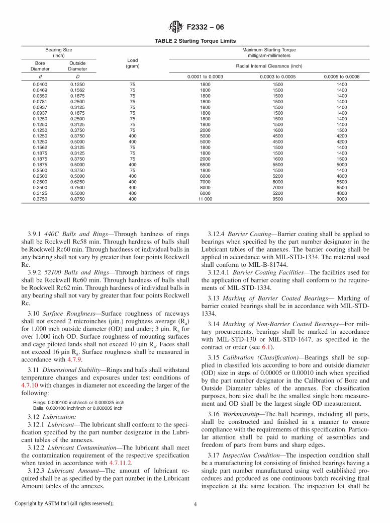
3.7.1 Starting Torque—Maximum starting torque shall be inaccordance with the values listed in Table 2.
3.8 Ball Quality—The minimum quality level of ball geom-etry and surface roughness for all bearings of both ABECtolerance levels shall be a Grade 5 (G5) as selected from thegrade levels specified in ABMA Standard 10/ISO 3290. Theballs in each bearing shall come from the same ball lot or beinspected to be G5.
3.9 Hardness of Balls and Rings :
TABLE 1 Surface Roundness
Precision Level(ABEC)
Raceways(µin.)
5 507 40
F2332 − 06
3Copyright by ASTM Int'l (all rights reserved);
3.9.1 440C Balls and Rings—Through hardness of ringsshall be Rockwell Rc58 min. Through hardness of balls shallbe Rockwell Rc60 min. Through hardness of individual balls inany bearing shall not vary by greater than four points RockwellRc.
3.9.2 52100 Balls and Rings—Through hardness of ringsshall be Rockwell Rc60 min. Through hardness of balls shallbe Rockwell Rc62 min. Through hardness of individual balls inany bearing shall not vary by greater than four points RockwellRc.
3.10 Surface Roughness—Surface roughness of racewaysshall not exceed 2 microinches (µin.) roughness average (Ra)for 1.000 inch outside diameter (OD) and under; 3 µin. Ra forover 1.000 inch OD. Surface roughness of mounting surfacesand cage piloted lands shall not exceed 10 µin Ra. Faces shallnot exceed 16 µin Ra. Surface roughness shall be measured inaccordance with 4.7.9.
3.11 Dimensional Stability—Rings and balls shall withstandtemperature changes and exposures under test conditions of4.7.10 with changes in diameter not exceeding the larger of thefollowing:
Rings: 0.000100 inch/inch or 0.000025 inchBalls: 0.000100 inch/inch or 0.000005 inch
3.12 Lubrication:3.12.1 Lubricant—The lubricant shall conform to the speci-
fication specified by the part number designator in the Lubri-cant tables of the annexes.
3.12.2 Lubricant Contamination—The lubricant shall meetthe contamination requirement of the respective specificationwhen tested in accordance with 4.7.11.2.
3.12.3 Lubricant Amount—The amount of lubricant re-quired shall be as specified by the part number in the LubricantAmount tables of the annexes.
3.12.4 Barrier Coating—Barrier coating shall be applied tobearings when specified by the part number designator in theLubricant tables of the annexes. The barrier coating shall beapplied in accordance with MIL-STD-1334. The material usedshall conform to MIL-B-81744.
3.12.4.1 Barrier Coating Facilities—The facilities used forthe application of barrier coating shall conform to the require-ments of MIL-STD-1334.
3.13 Marking of Barrier Coated Bearings— Marking ofbarrier coated bearings shall be in accordance with MIL-STD-1334.
3.14 Marking of Non-Barrier Coated Bearings—For mili-tary procurements, bearings shall be marked in accordancewith MIL-STD-130 or MIL-STD-1647, as specified in thecontract or order (see 6.1).
3.15 Calibration (Classification)—Bearings shall be sup-plied in classified lots according to bore and outside diameter(OD) size in steps of 0.00005 or 0.00010 inch when specifiedby the part number designator in the Calibration of Bore andOutside Diameter tables of the annexes. For classificationpurposes, bore size shall be the smallest single bore measure-ment and OD shall be the largest single OD measurement.
3.16 Workmanship—The ball bearings, including all parts,shall be constructed and finished in a manner to ensurecompliance with the requirements of this specification. Particu-lar attention shall be paid to marking of assemblies andfreedom of parts from burrs and sharp edges.
3.17 Inspection Condition—The inspection condition shallbe a manufacturing lot consisting of finished bearings having asingle part number manufactured using well established pro-cedures and produced as one continuous batch receiving finalinspection at the same location. The inspection lot shall be
TABLE 2 Starting Torque Limits
Bearing Size(inch)
Load(gram)
Maximum Starting Torquemilligram-millimeters
BoreDiameter
OutsideDiameter
Radial Internal Clearance (inch)
d D 0.0001 to 0.0003 0.0003 to 0.0005 0.0005 to 0.0008
0.0400 0.1250 75 1800 1500 14000.0469 0.1562 75 1800 1500 14000.0550 0.1875 75 1800 1500 14000.0781 0.2500 75 1800 1500 14000.0937 0.3125 75 1800 1500 14000.0937 0.1875 75 1800 1500 14000.1250 0.2500 75 1800 1500 14000.1250 0.3125 75 1800 1500 14000.1250 0.3750 75 2000 1600 15000.1250 0.3750 400 5000 4500 42000.1250 0.5000 400 5000 4500 42000.1562 0.3125 75 1800 1500 14000.1875 0.3125 75 1800 1500 14000.1875 0.3750 75 2000 1600 15000.1875 0.5000 400 6500 5500 50000.2500 0.3750 75 1800 1500 14000.2500 0.5000 400 6000 5200 48000.2500 0.6250 400 7000 6000 55000.2500 0.7500 400 8000 7000 65000.3125 0.5000 400 6000 5200 48000.3750 0.8750 400 11 000 9500 9000
F2332 − 06
4Copyright by ASTM Int'l (all rights reserved);

identified by a unique number (Manufacturer’s Lot ControlNumber) to be included on the bearing process sheets, pack-aging markings and associated certifications that accompanythe shipping paperwork. The manufacturer’s lot control num-ber shall be traceable to the finished bearing assembly while inits original packaging. The samples taken for acceptancetesting/inspection shall be randomly selected to ensure thatthey are representative of the lot. Component information shallbe maintained for each bearing assembly lot. Multiple compo-nent lots are permitted as long as this component informationis maintained.
4. Verification
4.1 Inspection Conditions—Unless otherwise specified, allinspections shall be performed in accordance with the testconditions specified herein or in the applicable test method.
4.2 Inspection Area Cleanliness—Inspection areas shallmeet the cleanliness requirements of ISO 14644-1, Class 5,Class 7.
4.3 Measurement Standards Calibration— Measurementstandards shall have calibrations in accordance with ISO10012-1 and NCSL Z540.1.
4.4 Measurement Temperature—Dimensional measurementmade at other than the standard calibration temperature shall becorrected for temperature effects.
4.5 Inspection Provisions—Alternate inspection proceduresand inspection equipment may be used by the contractor whensuch procedures and equipment provide, as a minimum, thequality assurance required in the contractual documents. Be-fore applying such alternative inspection procedures and in-spection equipment, the contractor shall describe them in awritten proposal and shall demonstrate for the approval of theprocuring representative that their effectiveness is equal orbetter than the contractual quality assurance procedure. Incases of dispute as to whether certain procedures of thecontractor’s inspection system provide equal assurance, thecontract and procedures of this specification shall apply.
4.6 Conformance Inspection Sample— An inspection lotshall consist of all bearings of a particular identificationnumber submitted for delivery at the same time. For each lot ofassembled bearings, the procuring activity quality assurancerepresentative shall specify the inspection level. If the inspec-tion level is not specified, the contractor shall use their standardinspection procedures.
4.6.1 Conformance Inspection—The sample shall be sub-jected to the applicable tests specified in Table 3, Groups A andB. Groups C and D shall be used only when specified by theprocuring activity.
4.7 Methods of Inspection:4.7.1 Material Inspections—Material inspection methods
shall be in accordance with the material specification.4.7.2 Passivation Tests—Passivation tests of corrosion-
resistant components shall be conducted in accordance with thecopper sulfate or high humidity tests of A380. Each componentshall be examined under 10× magnification to determinecompliance.
4.7.3 Visual Inspections—Inspection for conformance to therequirements of 3.5.1 through 3.5.4 shall be made using a 10×binocular microscope. All other visual inspections shall bemade without magnification. The classification of defects,Table 4, shall be used to classify the defects found.
4.7.4 Dimensional Inspections:4.7.4.1 Boundary Dimensions Inspection— The bearing di-
mensions required in 3.6.1 and respective tolerance classrequired in 3.6.2 shall be measured with closures attached inaccordance with ABMA Standard 12.2 and ISO 1224.
4.7.4.2 Roundness Measurements—Roundness measure-ments specifying MRS method microinch values (see 3.6.3)shall be made on equipment meeting ASME Standard B89.3.1.Such equipment shall include means to provide a permanentrecording on either strip or polar chart-type recorders.
4.7.5 Radial Internal Clearance—Radial internal clearanceshall be measured with closures removed and the bearinglubricated with a thin film of oil. Gage pressure shall be theminimum required to overcome friction and weight of movingparts and obtain repeatable readings. Radial internal clearanceshall be the average of three measurements taken with eachmeasurement using a different position of the outer race. Themeasurements shall be made by comparison with a bearing ofknown radial play or by the method described in ABMAStandards 12.2 and ISO 1224.
TABLE 3 Conformance Inspection
InspectionRequirement
ParagraphTest
Paragraph
Group ADesign and constructionRetainer materialClosuresClosure attachmentSurface appearanceCracks and fracturesMaterial imperfectionsParticulate contaminationWorkmanshipBarrier coatingPacking, Preservation, Packaging andPackage Marking
3.33.2.23.43.4.13.5.13.5.23.5.33.5.43.163.12.33.14
4.7.34.7.34.7.34.7.34.7.34.7.34.7.34.7.34.7.34.7.11.34.7.3
Group BBoundary dimensionsTolerance ClassRadial internal clearanceContact anglePerformance test
Starting torqueHardness-Balls/RingsCalibration (Classification)
3.6.13.6.23.6.43.6.53.7
3.7.13.93.15
4.7.4.14.7.4.24.7.54.7.5.1ApplicableAnnex4.7.6.14.7.84.7.12
Group CPassivationBall qualityRoundnessSurface roughnessHardness of balls and ringsDimensional stabilityLubricantLubricant cleanliness
3.2.1.23.83.6.33.103.93.113.12.13.12.1
4.7.24.7.74.7.4.24.7.94.7.84.7.104.7.11.14.7.11.2
Group DBall and ring material testingMaterial cleanliness testingShield material testingSnap ring material testingSeal material testing
3.2.13.2.1.13.2.33.2.43.2.5
4.7.14.7.14.7.14.7.14.7.1
F2332 − 06
5Copyright by ASTM Int'l (all rights reserved);

4.7.5.1 Contact Angle—When the part number designator inthe Radial Internal Clearance tables of the annexes for angularcontact bearings specifies a contact angle, the bearing shall bemounted in such a manner that no radial distortion is caused byan interference fit. The test fixture shall be set up to impart a netthrust not to exceed 2 lb. The inner race or the outer race of the
bearing shall be rotated at a constant speed while the speed ofthe retainer (rolling element pitch diameter) is determined. Thenumber of revolutions of the retainer shall be counted wheneither the inner or the outer race is rotated. Diametric valuesshall be determined and recorded for use in the followingapplicable formulas:
Rotating Inner Race:
b 5 cos21 F Ed F 1 2
2NeNi G G (1)
Rotating Outer Race:
b 5 cos21 F Ed F 2Ne
No2 1G G (2)
where:Ne = rpm of pitch circle,Ni = rpm of rotating inner race,No = rpm of rotating outer race,E = pitch diameter,b = contact angle, andd = ball diameter.
4.7.6 Torque Tests:4.7.6.1 Starting Torque Test—Starting torque test method
shall be in accordance with MIL-STD-206.4.7.7 Ball Quality Inspections—Ball diameter measure-
ments shall be based on comparative measurements withmaster balls. The measurements of master balls and balls beingtested shall be made at the same temperature and with the samegage pressure (see Table 5). If the master balls are of a differentmaterial than the balls being tested, readings shall be referredto zero gage pressure and a temperature of 68 6 3°F.Conformance to the ball quality requirements specified in ISO3290 apply.
4.7.7.1 Diameter Variations per Ball—The differences be-tween the maximum diameter measured and the minimumdiameter measured on each ball is the maximum diametervariation of that ball per ISO 3290.
4.7.7.2 Ball Diameter Variation per Bearing—The averagediameter of each ball shall be computed by averaging fivemeasurements of that ball. The difference between the average
TABLE 4 Classification of Defects
Category Description of Defect Requirement
Critical Incorrect material 3.2.1 through 3.2.5Incorrect design and construction 3.3Incorrect retainer type 3.3Incorrect number, type or locationof closures
3.4
Closures not securely attached 3.4.1Cracks or fractures in anycomponents
3.5.2
Barrier coat on raceways,retainers, or ring lands
3.12.3
Major Passivation 3.2.1.2Burrs, dents or folded material onclosures
3.5.1
Delimitation or burring of non-metallic retainers
3.5.1
Material break out of non-metallicretainers
3.5.3
Particulate contamination 3.5.4Boundary dimensions
Outer ring outside diameter (OD) 3.6.1Outer ring OD out-of-round 3.6.2Outer ring OD taper 3.6.2Outer ring radial runout 3.6.2Outer ring width variation 3.6.2Outer ring OD runout with
reference face3.6.2
Outer ring corner radii 3.6.1Outer ring OD/flange face
undercut3.6.2
Inner ring bore diameter 3.6.1Inner ring bore out-of-round 3.6.2Inner ring radial runout 3.6.2Inner ring width variation 3.6.2Inner ring bore taper 3.6.2Inner ring bore runout with
reference face3.6.2
Inner ring corner radii 3.6.1Radial internal clearance or contactangle
3.6.4 or 3.6.5
Starting torque 3.7.1Ball quality 3.8Hardness of balls and rings 3.9Surface roughness of raceways 3.10Incorrect lubricant 3.12.1Barrier coating missing fromrequired surface
3.12.3
Calibration 3.15Minor Snap rings not easily removable 3.5.1
Surfaces do not meet visualrequirements
3.5.1 through 3.5.4
Boundary dimensionsOuter ring width 3.6.1Outer ring flange width 3.6.1Outer ring flange OD 3.6.1Outer ring OD roundness 3.6.1Outer ring raceway roundness 3.6.2 and 3.6.3Inner ring bore roundness 3.6.2 and 3.6.3Inner ring raceway roundness 3.6.2 and 3.6.3Outer ring raceway runout to
reference side3.6.2
Inner ring raceway runout toreference side
3.6.2
Surface roughness of mountingsurface, levels and surfaces
3.10
Marking for identification 3.14
TABLE 5 Standard Oil Quantities
Number of drops, #26 BD needle 1A
BallDiameter
Number of Balls
5 6 7 8 9 10 11 12
0.0250 1 1 1 1 1 1 1 10.0312 1 1 1 1 1 1 1 10.0394 1 1 1 1 1 1 2 20.0625 1 2 2 2 2 2 3 30.0937 2 3 3 3 3 3 4 40.1250 3 3 3 3 3 3 4 40.1406 3 4 4 4 4 4 4 40.1562 3 4 4 4 4 4 4 40.1875 4 4 4 4 4 4 5 50.2187 4 4 4 4 5 5 5 5
A Oil: Lubricate bearing with the indicated number of drops with a 50/50 mixture byvolume of oil and solvent and allow solvent to evaporate. (The properties of the oilshall not change after evaporation of the solvent.) Minimum quantity for Gimbalbearings (one drop).
F2332 − 06
6Copyright by ASTM Int'l (all rights reserved);

diameter of the largest ball and the average diameter of thesmallest ball in a bearing is the ball diameter variation of thebearing.
4.7.8 Hardness Tests—The bearings selected for this testshall not be the same bearings used for the dimensionalstability test. If, because of limited size of surface or for othervalid reasons, Rockwell C scale measurements are not feasible,other methods of measuring hardness may be used, providedcorrelation with the Rockwell C scale measurement values isestablished. When lighter loads are used, conversion to Rock-well C shall be through the use of charts in HardnessConversion Tables E140. Hardness tests shall be made on flatsurfaces.
4.7.9 Surface Roughness Tests—Measurements from lessthan 1 to 1000 µin. shall be made with equipment meeting therequirements of ASME B46.1. Such equipment shall allowmeasurements on most surfaces including fine finished or softmaterials. The equipment shall include means to provide apermanent graphical plot of the data. Minimum cutoff wave-length shall be determined by dividing width of surface to bemeasured by ten and selecting the next lowest preferred cutoffwavelength, either 0.001, 0.003, 0.01, or 0.03 in. In deepgroove raceways, the width of the surface is the distance fromthe bottom of the race to either land corner.
4.7.10 Dimensional Stability Tests—The dimensional stabil-ity of rings and balls shall be demonstrated by the followingtest: The rings and balls shall be subjected to a temperature of−80 6 3°F for 25 hr 6 30 min. Immediately following, theparts shall be subjected to a temperature of +302 6 3°F for 25hr 6 30 min. This cycle shall then be repeated for a total of 100hours. Diameter shall be measured at 68 6 3°F and comparedto values recorded before temperature cycling.
4.7.11 Lubricant Inspections:4.7.11.1 Lubricant—Lubricant shall meet the OEM, NSN,
Source Control, Spec Control drawing requirements. Whenrequired, conformity to a lubricant specification shall beverified by analysis with an infrared spectrometer.
4.7.11.2 Lubricant Contamination Tests— All tests shall beperformed in a ISO 14644–1, Class 5 environment. Samplebearings shall be tested for lubricant contamination by thefollowing procedure: When required by contract, the bearingsupplier shall take three random samples from the lubricatingfixture or container of lubricant if a fixture is not used, at thetime bearings are lubricated. Samples of grease shall beprepared and read for dirt count in accordance with FED-STD-791, Method 3005. Samples of oil shall be prepared and readfor dirt count in accordance with FED-STD-791, Method 3004or D2273. The bearing’s supplier shall maintain the sample andinspection report for examination by the procuring activity’srepresentative and shall certify that the sample was taken fromthe lubricant used to lubricate the bearings.
4.7.11.3 Barrier Coat Inspection—Barrier coated bearingsshall be inspected in accordance with MIL-STD-1334.
4.7.12 Calibration Classification Inspection—Bore and ODmeasurements of 4.7.4.1 shall be used to verify conformance tocalibration requirements. Individual measurements as specifiedin 3.6.1 shall be used rather than average values.
5. Packing, Preservation, Packaging and PackageMarking
5.1 Packing—For acquisition purposes, the packing require-ments shall be as specified in the contract or order (see 6.1).
5.1.1 Preservation and Packaging—For military procure-ments, preservation and packaging shall be in accordance withMIL-DTL-197, Method 41B.
5.1.2 Package Marking—For military procurements, pack-age marking shall be in accordance with MIL-STD-129.Special marking requirements shall be as specified in thecontract or order.
6. Supplementary Requirements
6.1 Acquisition Requirements—Procurement documentsshould specify the following:
6.1.1 Title, number, and date of the specification.6.1.2 Quantity and part identifying number (PIN) of the
bearing required.6.1.3 Ring, ball, retainer, and closure materials (see 3.2).6.1.4 Number, type, and location of closures (see 3.4).6.1.5 Boundary dimensions (see 3.6.1).6.1.6 Bearing precision level ABEC tolerances (see 3.6.2).6.1.7 Radial internal clearance or contact angle (see 3.6.4
and 3.6.5).6.1.8 Type and amount of lubricant (see 3.12.1 and 3.12.3).6.1.9 Barrier coating requirements (see 3.12.4).6.1.10 Performance tests required (see 3.7).6.1.11 Packing, preservation, packaging and package mark-
ing requirements (see Section 5).6.1.12 Marking requirements (see 3.14).
6.2 Envelope Dimension Size Availability—The listing of aparticular envelope dimension size of a bearing in a specifica-tion sheet does not guarantee availability from every manufac-turer. Shields or seals, for instance, may not be available on thethinner widths of a particular bore and OD. Recommendverification of availability from industry sources before assign-ment of PIN.
7. Keywords
7.1 ABEC 5P; ABEC 7P; angular contact; barrier coating;bearing void; calibration (classification); contact angle; coun-terbored outer ring; deep groove radial; extended inner ring;instrument bearing; nonseparable; passivation; precision bear-ing; separable; starting torque; stepped inner ring
F2332 − 06
7Copyright by ASTM Int'l (all rights reserved);

ANNEXES
(Mandatory Information)
A1. ANNULAR BALL BEARINGS FOR INSTRUMENTS AND PRECISION ROTATING COMPONENTS, DEEP GROOVE, UN-FLANGED, CHROMIUM ALLOY STEEL, ABEC 5P
A1.1 Requirements
A1.1.1 Design—All bearings described in this specificationsheet shall be deep groove instrument bearings, unflanged.
A1.1.2 Material—The ball and ring material for these bear-ings shall be chromium-alloy steel 52100 (UNS G52986)conforming to SAE-AMS 6444.
A1.1.3 Tolerance Class— The tolerance class shall be inaccordance with the ABEC 5P tolerance tables of ABMAStandard 12.2. This tolerance class shall apply to all bearingsizes listed in Table A1.1.
A1.1.4 Boundary Dimensions—The boundary dimensionsshall be as specified by the dash number (Dash No.) in TableA1.1.
A1.1.5 Retainer—The retainer shall be as specified by thepart number designator (PN Des) in Table A1.2.
A1.1.6 Closures—The closures shall be as specified by thepart number designator in Table A1.3.
A1.1.7 Radial Internal Clearance —The radial internalclearance shall be as specified by the part number designator inTable A1.4.
A1.1.8 Calibration— The calibration shall be as specifiedby the part number designator in Table A1.5.
A1.1.9 Performance Test—The performance test shall be asspecified by the part number designator in Table A1.6.
A1.1.10 Lubrication:
A1.1.10.1 Lubricant—The lubricant shall be in accordancewith the specification specified by the part number designatorin Table A1.7.
A1.1.10.2 Lubricant Amount—The amount of lubricantshall be as specified by the part number designator in TableA1.8.
A1.1.10.3 Barrier Coating— The barrier coating shall beapplied to bearings as specified by the part number designatorin Table A1.7.
A1.1.11 Part Number— The part number consists of thefollowing: prefix letter M; general specification number; num-ber of this specification sheet; dash number; and characters for:retainer, closures, radial internal clearance, calibration, perfor-mance test, lubricant, and lubricant amount (see Fig. A1.2).
FIG. A1.1 Bearing Configuration
F2332 − 06
8Copyright by ASTM Int'l (all rights reserved);

TABLE A1.1 Boundary Dimensions, inches
DashNo.
Bored
ODD
WidthC
RadiusrA
-AA 0.0400 0.1250 0.0469 0.003-BA 0.0469 0.1562 0.0625 0.003-BC 0.0469 0.1562 0.0937 0.003-CA 0.0550 0.1875 0.0781 0.003-CB 0.0550 0.1875 0.1094 0.003-DA 0.0781 0.2500 0.0937 0.003-DB 0.0781 0.2500 0.1406 0.003-DC 0.0781 0.2500 0.1094 0.003-EA 0.0937 0.1875 0.0625 0.003-EB 0.0937 0.1875 0.0937 0.003-EC 0.0937 0.2500 0.0625 0.003-ED 0.0937 0.2500 0.0937 0.003-EE 0.0937 0.2500 0.1094 0.003-EF 0.0937 0.2883 0.0625 0.003-EG 0.0937 0.3125 0.0625 0.003-EH 0.0937 0.3125 0.1094 0.003-EJ 0.0937 0.3125 0.1406 0.003-EK 0.0937 0.4100 0.1094 0.003-FA 0.1250 0.2500 0.0937 0.003-FB 0.1250 0.2500 0.1094 0.003-FC 0.1250 0.3125 0.1094 0.003-FD 0.1250 0.3125 0.1406 0.003-FE 0.1250 0.3750 0.1094 0.005-FF 0.1250 0.3750 0.1406 0.005-FG 0.1250 0.3750 0.1562 0.012-FH 0.1250 0.4100 0.0937 0.003-FJ 0.1250 0.4100 0.1094 0.003-FK 0.1250 0.4250 0.0937 0.003-FL 0.1250 0.4250 0.1094 0.003-FM 0.1250 0.4375 0.1094 0.003-FN 0.1250 0.4375 0.1406 0.003-FP 0.1250 0.5000 0.1094 0.003-FR 0.1250 0.5000 0.1719 0.012-FT 0.1250 0.7500 0.1250 0.010-FV 0.1250 0.3750 0.0937 0.003-GA 0.1562 0.3125 0.1094 0.003-GB 0.1562 0.3125 0.1250 0.003-HA 0.1875 0.3125 0.1094 0.003-HB 0.1875 0.3125 0.1250 0.003-HC 0.1875 0.3750 0.1094 0.003-HD 0.1875 0.3750 0.1250 0.003-HE 0.1875 0.4100 0.1094 0.003-HF 0.1875 0.4250 0.1094 0.003-HG 0.1875 0.4375 0.1094 0.003-HH 0.1875 0.5000 0.1094 0.003-HJ 0.1875 0.5000 0.1562 0.012-HK 0.1875 0.5000 0.1960 0.012-HL 0.1875 0.7435 0.1960 0.012-HM 0.1875 0.7500 0.1960 0.012-HN 0.1875 0.8750 0.1960 0.012-JA 0.2500 0.3750 0.1250 0.003-JB 0.2500 0.5000 0.1094 0.003-JC 0.2500 0.5000 0.1250 0.005-JD 0.2500 0.5000 0.1875 0.005-JE 0.2500 0.6250 0.1960 0.012-JF 0.2500 0.7500 0.1960 0.012-JG 0.2500 0.7500 0.2188 0.016-JH 0.2500 0.7500 0.2812 0.016-JJ 0.2500 0.8750 0.1960 0.012-JK 0.2500 1.0000 0.1960 0.012-JL 0.2500 1.0480 0.1960 0.012-KA 0.3125 0.5000 0.1562 0.005-KB 0.3125 0.6250 0.1562 0.010-LA 0.3750 0.8750 0.2188 0.016-LB 0.3750 0.8750 0.2812 0.016-MA 0.5000 0.8750 0.2188 0.016-MB 0.5000 0.8750 0.2812 0.016-MC 0.5000 1.1250 0.2500 0.016-MD 0.5000 1.1250 0.3125 0.016-NA 0.6250 1.3750 0.2812 0.031-NB 0.6250 1.3750 0.3438 0.031
A Maximum shaft or housing fillet radius that bearing corners will clear.
TABLE A1.2 Retainer
PN Des Type
0 no retainer, full complement1 manufacturer’s standardA
2 crownB
3 ribbon, tight-clinchedB
4 ribbon, loose-clinchedC
5 PTFE tube separatorD
7 phenolic laminateE ,F
8 vacuum-impregnated phenolicF ,G
9 nonporous, nonmetallic crownF
A One-piece pressed corrosion-resistant steel crown or two-piece pressedcorrosion-resistant steel ribbon.B One-piece pressed corrosion-resistant steel.C Two-piece pressed corrosion-resistant steel.D PTFE (polytetrafluoroethylene).E Phenolic or other porous nonmetallic material.F Used for high-speed applications.G Phenolic or other porous nonmetallic material saturated with lubricant. Selectionof this choice dictates choosing manufacturer’s standard amount of lubricant.
TABLE A1.3 Closures
PN Des Number Type
N none noneA one shieldA
C two shieldA
D one sealB
E one sealC
H two sealB
J two sealC
A Corrosion-resistant steel conforming to Specification A580/A580M, Condition A;Specification A240/A240M; Specification A756; or Specification A666 (for shield)and Specification A313/A313M, Type 302, Class 1, or SAE-AMS 5688 for snaprings.B Synthetic rubber.C Glass fiber (polytetrafluoroethylene) or other inert fiber.
TABLE A1.4 Radial Internal Clearance
PN Des Range, in.
1 0.0001 to 0.00032 0.0003 to 0.00055 0.0005 to 0.00088 0.0008 to 0.00119 As specified in contract
TABLE A1.5 Calibration of Bore and Outside Diameter (OD)
PN Des Bore Increments OD Increments
N no calibration no calibrationA no calibration 0.00010B no calibration 0.00005C 0.00010 no calibrationD 0.00010 0.00010E 0.00010 0.00005F 0.00005 no calibrationG 0.00005 0.00010H 0.00005 0.00005
F2332 − 06
9Copyright by ASTM Int'l (all rights reserved);

TABLE A1.6 Performance Test
PN Des Type
1 manufacturer’s standard2 starting torqueA
A Starting torque limits from Table 2 of base document.
TABLE A1.7 Lubricant
PN Des Specification
P preservativeA
A MIL-PRF-6085B MIL-PRF-6085B
C DOD-L-81846D DOD-L-81846B
E MIL-PRF-23827F MIL-PRF-81322G MIL-G-81937H MIL-PRF-83261J MIL-S-81087C
K MIL-S-81087C
L MIL-DTL-53131, Grade 4M MIL-DTL-53131, Grade 6N MIL-DTL-53131, Grade 9Q MIL-DTL-53131, Grade 14R MIL-DTL-53131, Grade 40S As specified in contract
A PN Des “P” shall be used only with PN Des “P” in Table A1.8.B With barrier coat.C Canceled – lube no longer manufactured.
TABLE A1.8 Lubricant Amount
PN Des Quantity
P preservative amount as required byMIL-DTL-197
1 manufacturer’s standardA
2 oil per Table 5 of base document3 15 % grease4 25 % grease5 35 % grease6 45 % grease7 As specified in contract
A Grease: fill to minimum 25 %, maximum 40 % of bearing void. Oil: immerse andthen allow excess to drip off. The standard quantity of oil varies with each bearingsize.
F2332 − 06
10Copyright by ASTM Int'l (all rights reserved);

FIG. A1.2 Part Number
F2332 − 06
11Copyright by ASTM Int'l (all rights reserved);

A2. ANNULAR BALL BEARINGS FOR INSTRUMENTS AND PRECISION ROTATING COMPONENTS, DEEP GROOVE, UN-FLANGED, CHROMIUM ALLOY STEEL, ABEC 7P
A2.1 Requirements
A2.1.1 Design—All bearings described in this specificationsheet shall be deep groove instrument bearings, unflanged.
A2.1.2 Material—The ball and ring material for these bear-ings shall be chromium-alloy steel 52100 (UNS G52986)conforming to SAE-AMS 6444.
A2.1.3 Tolerance Class— The tolerance class shall be inaccordance with the ABEC 7P tolerance tables of ABMAStandard 12.2. This tolerance class shall apply to all bearingsizes listed in Table A2.1.
A2.1.4 Boundary Dimensions—The boundary dimensionsshall be as specified by the dash number (Dash No.) in TableA2.1.
A2.1.5 Retainer—The retainer shall be as specified by thepart number designator (PN Des) in Table A2.2.
A2.1.6 Closures—The closures shall be as specified by thepart number designator in Table A2.3.
A2.1.7 Radial Internal Clearance —The radial internalclearance shall be as specified by the part number designator inTable A2.4.
A2.1.8 Calibration— The calibration shall be as specifiedby the part number designator in Table A2.5.
A2.1.9 Performance Test—The performance test shall be asspecified by the part number designator in Table A2.6.
A2.1.10 Lubrication:
A2.1.10.1 Lubricant—The lubricant shall be in accordancewith the specification specified by the part number designatorin Table A2.7.
A2.1.10.2 Lubricant Amount—The amount of lubricantshall be as specified by the part number designator in TableA2.8.
A2.1.10.3 Barrier Coating— The barrier coating shall beapplied to bearings as specified by the part number designatorin Table A2.7.
A2.1.11 Part Number— The part number consists of thefollowing: prefix letter M; general specification number; num-ber of this specification sheet; dash number; and characters for:retainer, closures, radial internal clearance, calibration, perfor-mance test, lubricant, and lubricant amount (see Fig. A2.2).
FIG. A2.1 Bearing Configuration
F2332 − 06
12Copyright by ASTM Int'l (all rights reserved);

TABLE A2.1 Boundary Dimensions, inches
DashNo.
Bored
ODD
WidthC
RadiusrA
-AA 0.0400 0.1250 0.0469 0.003-BA 0.0469 0.1562 0.0625 0.003-BC 0.0469 0.1562 0.0937 0.003-CA 0.0550 0.1875 0.0781 0.003-CB 0.0550 0.1875 0.1094 0.003-DA 0.0781 0.2500 0.0937 0.003-DB 0.0781 0.2500 0.1406 0.003-DC 0.0781 0.2500 0.1094 0.003-EA 0.0937 0.1875 0.0625 0.003-EB 0.0937 0.1875 0.0937 0.003-EC 0.0937 0.2500 0.0625 0.003-ED 0.0937 0.2500 0.0937 0.003-EE 0.0937 0.2500 0.1094 0.003-EF 0.0937 0.2883 0.0625 0.003-EG 0.0937 0.3125 0.0625 0.003-EH 0.0937 0.3125 0.1094 0.003-EJ 0.0937 0.3125 0.1406 0.003-EK 0.0937 0.4100 0.1094 0.003-FA 0.1250 0.2500 0.0937 0.003-FB 0.1250 0.2500 0.1094 0.003-FC 0.1250 0.3125 0.1094 0.003-FD 0.1250 0.3125 0.1406 0.003-FE 0.1250 0.3750 0.1094 0.005-FF 0.1250 0.3750 0.1406 0.005-FG 0.1250 0.3750 0.1562 0.012-FH 0.1250 0.4100 0.0937 0.003-FJ 0.1250 0.4100 0.1094 0.003-FK 0.1250 0.4250 0.0937 0.003-FL 0.1250 0.4250 0.1094 0.003-FM 0.1250 0.4375 0.1094 0.003-FN 0.1250 0.4375 0.1406 0.003-FP 0.1250 0.5000 0.1094 0.003-FR 0.1250 0.5000 0.1719 0.012-FT 0.1250 0.7500 0.1250 0.010-FV 0.1250 0.3750 0.0937 0.003-GA 0.1562 0.3125 0.1094 0.003-GB 0.1562 0.3125 0.1250 0.003-HA 0.1875 0.3125 0.1094 0.003-HB 0.1875 0.3125 0.1250 0.003-HC 0.1875 0.3750 0.1094 0.003-HD 0.1875 0.3750 0.1250 0.003-HE 0.1875 0.4100 0.1094 0.003-HF 0.1875 0.4250 0.1094 0.003-HG 0.1875 0.4375 0.1094 0.003-HH 0.1875 0.5000 0.1094 0.003-HJ 0.1875 0.5000 0.1562 0.012-HK 0.1875 0.5000 0.1960 0.012-HL 0.1875 0.7435 0.1960 0.012-HM 0.1875 0.7500 0.1960 0.012-HN 0.1875 0.8750 0.1960 0.012-JA 0.2500 0.3750 0.1250 0.003-JB 0.2500 0.5000 0.1094 0.003-JC 0.2500 0.5000 0.1250 0.005-JD 0.2500 0.5000 0.1875 0.005-JE 0.2500 0.6250 0.1960 0.012-JF 0.2500 0.7500 0.1960 0.012-JG 0.2500 0.7500 0.2188 0.016-JH 0.2500 0.7500 0.2812 0.016-JJ 0.2500 0.8750 0.1960 0.012-JK 0.2500 1.0000 0.1960 0.012-JL 0.2500 1.0480 0.1960 0.012-KA 0.3125 0.5000 0.1562 0.005-KB 0.3125 0.6250 0.1562 0.010-LA 0.3750 0.8750 0.2188 0.016-LB 0.3750 0.8750 0.2812 0.016-MA 0.5000 0.8750 0.2188 0.016-MB 0.5000 0.8750 0.2812 0.016-MC 0.5000 1.1250 0.2500 0.016-MD 0.5000 1.1250 0.3125 0.016-NA 0.6250 1.3750 0.2812 0.031-NB 0.6250 1.3750 0.3438 0.031
A Maximum shaft or housing fillet radius that bearing corners will clear.
TABLE A2.2 Retainer
PN Des Type
0 no retainer, full complement1 manufacturer’s standardA
2 crownB
3 ribbon, tight-clinchedB
4 ribbon, loose-clinchedC
5 PTFE tube separatorD
7 phenolic laminateE ,F
8 vacuum-impregnated phenolicF ,G
9 nonporous, nonmetallic crownF
A One-piece pressed corrosion-resistant steel crown or two-piece pressedcorrosion-resistant steel ribbon.B One-piece pressed corrosion-resistant steel.C Two-piece pressed corrosion-resistant steel.D PTFE (polytetrafluoroethylene).E Phenolic or other porous nonmetallic material.F Used for high-speed applications.G Phenolic or other porous nonmetallic material saturated with lubricant. Selectionof this choice dictates choosing manufacturer’s standard amount of lubricant.
TABLE A2.3 Closures
PN Des Number Type
N none noneA one shieldA
C two shieldA
D one sealB
E one sealC
H two sealB
J two sealC
A Corrosion-resistant steel conforming to Specification A580/A580M, Condition A;Specification A240/A240M; Specification A756; or Specification A666 (for shield)and Specification A313/A313M, Type 302, Class 1, or SAE-AMS 5688 for snaprings.B Synthetic rubber.C Glass fiber (polytetrafluoroethylene) or other inert fiber.
TABLE A2.4 Radial Internal Clearance
PN Des Range, in.
1 0.0001 to 0.00032 0.0003 to 0.00055 0.0005 to 0.00088 0.0008 to 0.00119 As specified in contract
TABLE A2.5 Calibration of Bore and Outside Diameter (OD)
PN Des Bore Increments OD Increments
N no calibration no calibrationA no calibration 0.00010B no calibration 0.00005C 0.00010 no calibrationD 0.00010 0.00010E 0.00010 0.00005F 0.00005 no calibrationG 0.00005 0.00010H 0.00005 0.00005
F2332 − 06
13Copyright by ASTM Int'l (all rights reserved);

TABLE A2.6 Performance Test
PN Des Type
1 manufacturer’s standard2 starting torqueA
A Starting torque limits from Table 2 of base document.
TABLE A2.7 Lubricant
PN Des Specification
P preservativeA
A MIL-PRF-6085B MIL-PRF-6085B
C DOD-L-81846D DOD-L-81846B
E MIL-PRF-23827F MIL-PRF-81322G MIL-G-81937H MIL-PRF-83261J MIL-S-81087C
K MIL-S-81087C
L MIL-DTL-53131, Grade 4M MIL-DTL-53131, Grade 6N MIL-DTL-53131, Grade 9Q MIL-DTL-53131, Grade 14R MIL-DTL-53131, Grade 40S As specified in contract
A PN Des “P” shall be used only with PN Des “P” in Table A2.8.B With barrier coat.C Canceled – lube no longer manufactured.
TABLE A2.8 Lubricant Amount
PN Des Quantity
P preservative amount as required byMIL-DTL-197
1 manufacturer’s standardA
2 oil per Table 5 of base document3 15 % grease4 25 % grease5 35 % grease6 45 % grease7 As specified in contract
A Grease: fill to minimum 25 %, maximum 40 % of bearing void. Oil: immerse andthen allow excess to drip off. The standard quantity of oil varies with each bearingsize.
F2332 − 06
14Copyright by ASTM Int'l (all rights reserved);

FIG. A2.2 Part Number
F2332 − 06
15Copyright by ASTM Int'l (all rights reserved);

A3. ANNULAR BALL BEARINGS FOR INSTRUMENTS AND PRECISION ROTATING COMPONENTS, DEEP GROOVE, UN-FLANGED, CORROSIONRESISTANT STEEL, ABEC 5P
A3.1 Requirements
A3.1.1 Design—All bearings described in this specificationsheet shall be deep groove instrument bearings, unflanged.
A3.1.2 Material—The ball and ring material for these bear-ings shall be corrosion-resistant steel 440C (UNS S44004)conforming to SAE-AMS-QQ-S-763.
A3.1.3 Tolerance Class— The tolerance class shall be inaccordance with the ABEC 5P tolerance tables of ABMAStandard 12.2. This tolerance class shall apply to all bearingsizes listed in Table A3.1.
A3.1.4 Boundary Dimensions—The boundary dimensionsshall be as specified by the dash number (Dash No.) in TableA3.1.
A3.1.5 Retainer—The retainer shall be as specified by thepart number designator (PN Des) in Table A3.2.
A3.1.6 Closures—The closures shall be as specified by thepart number designator in Table A3.3.
A3.1.7 Radial Internal Clearance —The radial internalclearance shall be as specified by the part number designator inTable A3.4.
A3.1.8 Calibration— The calibration shall be as specifiedby the part number designator in Table A3.5.
A3.1.9 Performance Test—The performance test shall be asspecified by the part number designator in Table A3.6.
A3.1.10 Lubrication:
A3.1.10.1 Lubricant—The lubricant shall be in accordancewith the specification specified by the part number designatorin Table A3.7.
A3.1.10.2 Lubricant Amount—The amount of lubricantshall be as specified by the part number designator in TableA3.8.
A3.1.10.3 Barrier Coating— The barrier coating shall beapplied to bearings as specified by the part number designatorin Table A3.7.
A3.1.11 Part Number— The part number consists of thefollowing: prefix letter M; general specification number; num-ber of this specification sheet; dash number; and characters for:retainer, closures, radial internal clearance, calibration, perfor-mance test, lubricant, and lubricant amount (see Fig. A3.2).
FIG. A3.1 Bearing Configuration
F2332 − 06
16Copyright by ASTM Int'l (all rights reserved);
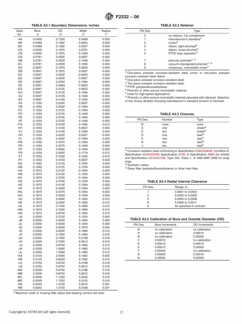
TABLE A3.1 Boundary Dimensions, inches
DashNo.
Bored
ODD
WidthC
RadiusrA
-AA 0.0400 0.1250 0.0469 0.003-BA 0.0469 0.1562 0.0625 0.003-BC 0.0469 0.1562 0.0937 0.003-CA 0.0550 0.1875 0.0781 0.003-CB 0.0550 0.1875 0.1094 0.003-DA 0.0781 0.2500 0.0937 0.003-DB 0.0781 0.2500 0.1406 0.003-DC 0.0781 0.2500 0.1094 0.003-EA 0.0937 0.1875 0.0625 0.003-EB 0.0937 0.1875 0.0937 0.003-EC 0.0937 0.2500 0.0625 0.003-ED 0.0937 0.2500 0.0937 0.003-EE 0.0937 0.2500 0.1094 0.003-EF 0.0937 0.2883 0.0625 0.003-EG 0.0937 0.3125 0.0625 0.003-EH 0.0937 0.3125 0.1094 0.003-EJ 0.0937 0.3125 0.1406 0.003-EK 0.0937 0.4100 0.1094 0.003-FA 0.1250 0.2500 0.0937 0.003-FB 0.1250 0.2500 0.1094 0.003-FC 0.1250 0.3125 0.1094 0.003-FD 0.1250 0.3125 0.1406 0.003-FE 0.1250 0.3750 0.1094 0.005-FF 0.1250 0.3750 0.1406 0.005-FG 0.1250 0.3750 0.1562 0.012-FH 0.1250 0.4100 0.0937 0.003-FJ 0.1250 0.4100 0.1094 0.003-FK 0.1250 0.4250 0.0937 0.003-FL 0.1250 0.4250 0.1094 0.003-FM 0.1250 0.4375 0.1094 0.003-FN 0.1250 0.4375 0.1406 0.003-FP 0.1250 0.5000 0.1094 0.003-FR 0.1250 0.5000 0.1719 0.012-FT 0.1250 0.7500 0.1250 0.010-FV 0.1250 0.3750 0.0937 0.003-GA 0.1562 0.3125 0.1094 0.003-GB 0.1562 0.3125 0.1250 0.003-HA 0.1875 0.3125 0.1094 0.003-HB 0.1875 0.3125 0.1250 0.003-HC 0.1875 0.3750 0.1094 0.003-HD 0.1875 0.3750 0.1250 0.003-HE 0.1875 0.4100 0.1094 0.003-HF 0.1875 0.4250 0.1094 0.003-HG 0.1875 0.4375 0.1094 0.003-HH 0.1875 0.5000 0.1094 0.003-HJ 0.1875 0.5000 0.1562 0.012-HK 0.1875 0.5000 0.1960 0.012-HL 0.1875 0.7435 0.1960 0.012-HM 0.1875 0.7500 0.1960 0.012-HN 0.1875 0.8750 0.1960 0.012-JA 0.2500 0.3750 0.1250 0.003-JB 0.2500 0.5000 0.1094 0.003-JC 0.2500 0.5000 0.1250 0.005-JD 0.2500 0.5000 0.1875 0.005-JE 0.2500 0.6250 0.1960 0.012-JF 0.2500 0.7500 0.1960 0.012-JG 0.2500 0.7500 0.2188 0.016-JH 0.2500 0.7500 0.2812 0.016-JJ 0.2500 0.8750 0.1960 0.012-JK 0.2500 1.0000 0.1960 0.012-JL 0.2500 1.0480 0.1960 0.012-KA 0.3125 0.5000 0.1562 0.005-KB 0.3125 0.6250 0.1562 0.010-LA 0.3750 0.8750 0.2188 0.016-LB 0.3750 0.8750 0.2812 0.016-MA 0.5000 0.8750 0.2188 0.016-MB 0.5000 0.8750 0.2812 0.016-MC 0.5000 1.1250 0.2500 0.016-MD 0.5000 1.1250 0.3125 0.016-NA 0.6250 1.3750 0.2812 0.031-NB 0.6250 1.3750 0.3438 0.031
A Maximum shaft or housing fillet radius that bearing corners will clear.
TABLE A3.2 Retainer
PN Des Type
0 no retainer, full complement1 manufacturer’s standardA
2 crownB
3 ribbon, tight-clinchedB
4 ribbon, loose-clinchedC
5 PTFE tube separatorD
7 phenolic laminateE ,F
8 vacuum-impregnated phenolicF ,G
9 nonporous, nonmetallic crownF
A One-piece pressed corrosion-resistant steel crown or two-piece pressedcorrosion-resistant steel ribbon.B One-piece pressed corrosion-resistant steel.C Two-piece pressed corrosion-resistant steel.D PTFE (polytetrafluoroethylene).E Phenolic or other porous nonmetallic material.F Used for high-speed applications.G Phenolic or other porous nonmetallic material saturated with lubricant. Selectionof this choice dictates choosing manufacturer’s standard amount of lubricant.
TABLE A3.3 Closures
PN Des Number Type
N none noneA one shieldA
C two shieldA
D one sealB
E one sealC
H two sealB
J two sealC
A Corrosion-resistant steel conforming to Specification A580/A580M, Condition A;Specification A240/A240M; Specification A756; or Specification A666 (for shield)and Specification A313/A313M, Type 302, Class 1, or SAE-AMS 5688 for snaprings.B Synthetic rubber.C Glass fiber (polytetrafluoroethylene) or other inert fiber.
TABLE A3.4 Radial Internal Clearance
PN Des Range, in.
1 0.0001 to 0.00032 0.0003 to 0.00055 0.0005 to 0.00088 0.0008 to 0.00119 As specified in contract
TABLE A3.5 Calibration of Bore and Outside Diameter (OD)
PN Des Bore Increments OD Increments
N no calibration no calibrationA no calibration 0.00010B no calibration 0.00005C 0.00010 no calibrationD 0.00010 0.00010E 0.00010 0.00005F 0.00005 no calibrationG 0.00005 0.00010H 0.00005 0.00005
F2332 − 06
17Copyright by ASTM Int'l (all rights reserved);

TABLE A3.6 Performance Test
PN Des Type
1 manufacturer’s standard2 starting torqueA
A Starting torque limits from Table 2 of base document.
TABLE A3.7 Lubricant
PN Des Specification
P preservativeA
A MIL-PRF-6085B MIL-PRF-6085B
C DOD-L-81846D DOD-L-81846B
E MIL-PRF-23827F MIL-PRF-81322G MIL-G-81937H MIL-PRF-83261J MIL-S-81087C
K MIL-S-81087C
L MIL-DTL-53131, Grade 4M MIL-DTL-53131, Grade 6N MIL-DTL-53131, Grade 9Q MIL-DTL-53131, Grade 14R MIL-DTL-53131, Grade 40S As specified in contract
A PN Des “P” shall be used only with PN Des “P” in Table A3.8.B With barrier coat.C Canceled – lube no longer manufactured.
TABLE A3.8 Lubricant Amount
PN Des Quantity
P preservative amount as required byMIL-DTL-197
1 manufacturer’s standardA
2 oil per Table 5 of base document3 15 % grease4 25 % grease5 35 % grease6 45 % grease7 As specified in contract
A Grease: fill to minimum 25 %, maximum 40 % of bearing void. Oil: immerse andthen allow excess to drip off. The standard quantity of oil varies with each bearingsize.
F2332 − 06
18Copyright by ASTM Int'l (all rights reserved);

FIG. A3.2 Part Number
F2332 − 06
19Copyright by ASTM Int'l (all rights reserved);

A4. ANNULAR BALL BEARINGS FOR INSTRUMENTS AND PRECISION ROTATING COMPONENTS, DEEP GROOVE, UN-FLANGED, CORROSIONRESISTANT STEEL, ABEC 7P
A4.1 Requirements
A4.1.1 Design—All bearings described in this specificationsheet shall be deep groove instrument bearings, unflanged.
A4.1.2 Material—The ball and ring material for these bear-ings shall be corrosion-resistant steel 440C (UNS S44004)conforming to SAE-AMS-QQ-S-763.
A4.1.3 Tolerance Class— The tolerance class shall be inaccordance with the ABEC 7P tolerance tables of ABMAStandard 12.2. This tolerance class shall apply to all bearingsizes listed in Table A4.1.
A4.1.4 Boundary Dimensions—The boundary dimensionsshall be as specified by the dash number (Dash No.) in TableA4.1.
A4.1.5 Retainer—The retainer shall be as specified by thepart number designator (PN Des) in Table A4.2.
A4.1.6 Closures—The closures shall be as specified by thepart number designator in Table A4.3.
A4.1.7 Radial Internal Clearance —The radial internalclearance shall be as specified by the part number designator inTable A4.4.
A4.1.8 Calibration— The calibration shall be as specifiedby the part number designator in Table A4.5.
A4.1.9 Performance Test—The performance test shall be asspecified by the part number designator in Table A4.6.
A4.1.10 Lubrication:
A4.1.10.1 Lubricant—The lubricant shall be in accordancewith the specification specified by the part number designatorin Table A4.7.
A4.1.10.2 Lubricant Amount—The amount of lubricantshall be as specified by the part number designator in TableA4.8.
A4.1.10.3 Barrier Coating— The barrier coating shall beapplied to bearings as specified by the part number designatorin Table A4.7.
A4.1.11 Part Number— The part number consists of thefollowing: prefix letter M; general specification number; num-ber of this specification sheet; dash number; and characters for:retainer, closures, radial internal clearance, calibration, perfor-mance test, lubricant, and lubricant amount (see Fig. A4.2).
FIG. A4.1 Bearing Configuration
F2332 − 06
20Copyright by ASTM Int'l (all rights reserved);

TABLE A4.1 Boundary Dimensions, inches
DashNo.
Bored
ODD
WidthC
RadiusrA
-AA 0.0400 0.1250 0.0469 0.003-BA 0.0469 0.1562 0.0625 0.003-BC 0.0469 0.1562 0.0937 0.003-CA 0.0550 0.1875 0.0781 0.003-CB 0.0550 0.1875 0.1094 0.003-DA 0.0781 0.2500 0.0937 0.003-DB 0.0781 0.2500 0.1406 0.003-DC 0.0781 0.2500 0.1094 0.003-EA 0.0937 0.1875 0.0625 0.003-EB 0.0937 0.1875 0.0937 0.003-EC 0.0937 0.2500 0.0625 0.003-ED 0.0937 0.2500 0.0937 0.003-EE 0.0937 0.2500 0.1094 0.003-EF 0.0937 0.2883 0.0625 0.003-EG 0.0937 0.3125 0.0625 0.003-EH 0.0937 0.3125 0.1094 0.003-EJ 0.0937 0.3125 0.1406 0.003-EK 0.0937 0.4100 0.1094 0.003-FA 0.1250 0.2500 0.0937 0.003-FB 0.1250 0.2500 0.1094 0.003-FC 0.1250 0.3125 0.1094 0.003-FD 0.1250 0.3125 0.1406 0.003-FE 0.1250 0.3750 0.1094 0.005-FF 0.1250 0.3750 0.1406 0.005-FG 0.1250 0.3750 0.1562 0.012-FH 0.1250 0.4100 0.0937 0.003-FJ 0.1250 0.4100 0.1094 0.003-FK 0.1250 0.4250 0.0937 0.003-FL 0.1250 0.4250 0.1094 0.003-FM 0.1250 0.4375 0.1094 0.003-FN 0.1250 0.4375 0.1406 0.003-FP 0.1250 0.5000 0.1094 0.003-FR 0.1250 0.5000 0.1719 0.012-FT 0.1250 0.7500 0.1250 0.010-FV 0.1250 0.3750 0.0937 0.003-GA 0.1562 0.3125 0.1094 0.003-GB 0.1562 0.3125 0.1250 0.003-HA 0.1875 0.3125 0.1094 0.003-HB 0.1875 0.3125 0.1250 0.003-HC 0.1875 0.3750 0.1094 0.003-HD 0.1875 0.3750 0.1250 0.003-HE 0.1875 0.4100 0.1094 0.003-HF 0.1875 0.4250 0.1094 0.003-HG 0.1875 0.4375 0.1094 0.003-HH 0.1875 0.5000 0.1094 0.003-HJ 0.1875 0.5000 0.1562 0.012-HK 0.1875 0.5000 0.1960 0.012-HL 0.1875 0.7435 0.1960 0.012-HM 0.1875 0.7500 0.1960 0.012-HN 0.1875 0.8750 0.1960 0.012-JA 0.2500 0.3750 0.1250 0.003-JB 0.2500 0.5000 0.1094 0.003-JC 0.2500 0.5000 0.1250 0.005-JD 0.2500 0.5000 0.1875 0.005-JE 0.2500 0.6250 0.1960 0.012-JF 0.2500 0.7500 0.1960 0.012-JG 0.2500 0.7500 0.2188 0.016-JH 0.2500 0.7500 0.2812 0.016-JJ 0.2500 0.8750 0.1960 0.012-JK 0.2500 1.0000 0.1960 0.012-JL 0.2500 1.0480 0.1960 0.012-KA 0.3125 0.5000 0.1562 0.005-KB 0.3125 0.6250 0.1562 0.010-LA 0.3750 0.8750 0.2188 0.016-LB 0.3750 0.8750 0.2812 0.016-MA 0.5000 0.8750 0.2188 0.016-MB 0.5000 0.8750 0.2812 0.016-MC 0.5000 1.1250 0.2500 0.016-MD 0.5000 1.1250 0.3125 0.016-NA 0.6250 1.3750 0.2812 0.031-NB 0.6250 1.3750 0.3438 0.031
A Maximum shaft or housing fillet radius that bearing corners will clear.
TABLE A4.2 Retainer
PN Des Type
0 no retainer, full complement1 manufacturer’s standardA
2 crownB
3 ribbon, tight-clinchedB
4 ribbon, loose-clinchedC
5 PTFE tube separatorD
7 phenolic laminateE ,F
8 vacuum-impregnated phenolicF ,G
9 nonporous, nonmetallic crownF
A One-piece pressed corrosion-resistant steel crown or two-piece pressedcorrosion-resistant steel ribbon.B One-piece pressed corrosion-resistant steel.C Two-piece pressed corrosion-resistant steel.D PTFE (polytetrafluoroethylene).E Phenolic or other porous nonmetallic material.F Used for high-speed applications.G Phenolic or other porous nonmetallic material saturated with lubricant. Selectionof this choice dictates choosing manufacturer’s standard amount of lubricant.
TABLE A4.3 Closures
PN Des Number Type
N none noneA one shieldA
C two shieldA
D one sealB
E one sealC
H two sealB
J two sealC
A Corrosion-resistant steel conforming to Specification A580/A580M, Condition A;Specification A240/A240M; Specification A756; or Specification A666 (for shield)and Specification A313/A313M, Type 302, Class 1, or SAE-AMS 5688 for snaprings.B Synthetic rubber.C Glass fiber (polytetrafluoroethylene) or other inert fiber.
TABLE A4.4 Radial Internal Clearance
PN Des Range, in.
1 0.0001 to 0.00032 0.0003 to 0.00055 0.0005 to 0.00088 0.0008 to 0.00119 As specified in contract
TABLE A4.5 Calibration of Bore and Outside Diameter (OD)
PN Des Bore Increments OD Increments
N no calibration no calibrationA no calibration 0.00010B no calibration 0.00005C 0.00010 no calibrationD 0.00010 0.00010E 0.00010 0.00005F 0.00005 no calibrationG 0.00005 0.00010H 0.00005 0.00005
F2332 − 06
21Copyright by ASTM Int'l (all rights reserved);

TABLE A4.6 Performance Test
PN Des Type
1 manufacturer’s standard2 starting torqueA
A Starting torque limits from Table 2 of base document.
TABLE A4.7 Lubricant
PN Des Specification
P preservativeA
A MIL-PRF-6085B MIL-PRF-6085B
C DOD-L-81846D DOD-L-81846B
E MIL-PRF-23827F MIL-PRF-81322G MIL-G-81937H MIL-PRF-83261J MIL-S-81087C
K MIL-S-81087C
L MIL-DTL-53131, Grade 4M MIL-DTL-53131, Grade 6N MIL-DTL-53131, Grade 9Q MIL-DTL-53131, Grade 14R MIL-DTL-53131, Grade 40S As specified in contract
A PN Des “P” shall be used only with PN Des “P” in Table A4.8.B With barrier coat.C Canceled – lube no longer manufactured.
TABLE A4.8 Lubricant Amount
PN Des Quantity
P preservative amount as required byMIL-DTL-197
1 manufacturer’s standardA
2 oil per Table 5 of base document3 15 % grease4 25 % grease5 35 % grease6 45 % grease7 As specified in contract
A Grease: fill to minimum 25 %, maximum 40 % of bearing void. Oil: immerse andthen allow excess to drip off. The standard quantity of oil varies with each bearingsize.
F2332 − 06
22Copyright by ASTM Int'l (all rights reserved);

FIG. A4.2 Part Number
F2332 − 06
23Copyright by ASTM Int'l (all rights reserved);

A5. ANNULAR BALL BEARINGS FOR INSTRUMENTS AND PRECISION ROTATING COMPONENTS, DEEP GROOVE,FLANGED, CHROMIUM ALLOY STEEL, ABEC 5P
A5.1 Requirements
A5.1.1 Design—All bearings described in this specificationsheet shall be deep groove instrument bearings, flanged.
A5.1.2 Material—The ball and ring material for these bear-ings shall be chromium-alloy steel 52100 (UNS G52986)conforming to SAE-AMS 6444.
A5.1.3 Tolerance Class— The tolerance class shall be inaccordance with the ABEC 5P tolerance tables of ABMAStandard 12.2. This tolerance class shall apply to all bearingsizes listed in Table A5.1.
A5.1.4 Boundary Dimensions—The boundary dimensionsshall be as specified by the dash number (Dash No.) in TableA5.1.
A5.1.5 Retainer—The retainer shall be as specified by thepart number designator (PN Des) in Table A5.2.
A5.1.6 Closures—The closures shall be as specified by thepart number designator in Table A5.3.
A5.1.7 Radial Internal Clearance —The radial internalclearance shall be as specified by the part number designator inTable A5.4.
A5.1.8 Calibration— The calibration shall be as specifiedby the part number designator in Table A5.5.
A5.1.9 Performance Test—The performance test shall be asspecified by the part number designator in Table A5.6.
A5.1.10 Lubrication:
A5.1.10.1 Lubricant—The lubricant shall be in accordancewith the specification specified by the part number designatorin Table A5.7.
A5.1.10.2 Lubricant Amount—The amount of lubricantshall be as specified by the part number designator in TableA5.8.
A5.1.10.3 Barrier Coating— The barrier coating shall beapplied to bearings as specified by the part number designatorin Table A5.7.
A5.1.11 Part Number— The part number consists of thefollowing: prefix letter M; general specification number; num-ber of this specification sheet; dash number; and characters for:retainer, closures, radial internal clearance, calibration, perfor-mance test, lubricant, and lubricant amount (see Fig. A5.2).
FIG. A5.1 Bearing Configuration
F2332 − 06
24Copyright by ASTM Int'l (all rights reserved);

TABLE A5.1 Boundary Dimensions, inches
DashNo.
Bored
ODD
WidthC
FlangeODD1
FlangeWidth
C1
RadiusrA
-AA 0.0400 0.1250 0.0469 0.171 0.013 0.003-BA 0.0469 0.1562 0.0625 0.203 0.013 0.003-BB 0.0469 0.1562 0.0937 0.203 0.031 0.003-CA 0.0550 0.1875 0.0781 0.234 0.023 0.003-CB 0.0550 0.1875 0.1094 0.234 0.031 0.003-DA 0.0781 0.2500 0.0937 0.296 0.023 0.003-DB 0.0781 0.2500 0.1406 0.296 0.031 0.003-EA 0.0937 0.1875 0.0625 0.234 0.018 0.003-EB 0.0937 0.1875 0.0937 0.234 0.031 0.003-EC 0.0937 0.3125 0.1094 0.359 0.023 0.003-ED 0.0937 0.3125 0.1406 0.359 0.031 0.003-FA 0.1250 0.2500 0.0937 0.296 0.023 0.003-FB 0.1250 0.2500 0.1094 0.296 0.031 0.003-FC 0.1250 0.3125 0.1094 0.359 0.023 0.003-FD 0.1250 0.3125 0.1406 0.359 0.031 0.003-FE 0.1250 0.3750 0.1094 0.422 0.023 0.005-FF 0.1250 0.3750 0.1406 0.422 0.031 0.005-FG 0.1250 0.3750 0.1562 0.440 0.030 0.012-GA 0.1562 0.3125 0.1094 0.359 0.023 0.003-GB 0.1562 0.3125 0.1250 0.359 0.036 0.003-HA 0.1875 0.3750 0.1250 0.422 0.023 0.003-HB 0.1875 0.3750 0.1250 0.422 0.031 0.003-HC 0.1875 0.5000 0.1562 0.565 0.042 0.012-HD 0.1875 0.5000 0.1960 0.565 0.042 0.012-HE 0.1875 0.3125 0.1094 0.359 0.023 0.003-HF 0.1875 0.3125 0.1250 0.359 0.036 0.003-JA 0.2500 0.3750 0.1250 0.422 0.023 0.003-JB 0.2500 0.3750 0.1250 0.422 0.036 0.003-JC 0.2500 0.5000 0.1250 0.547 0.023 0.005-JD 0.2500 0.5000 0.1875 0.547 0.045 0.005-JE 0.2500 0.6250 0.1960 0.690 0.042 0.012-KA 0.3125 0.5000 0.1562 0.547 0.031 0.005-LA 0.3750 0.8750 0.2188 0.969 0.062 0.016-LB 0.3750 0.8750 0.2812 0.969 0.062 0.016-MA 0.5000 1.1250 0.2500 1.225 0.062 0.016-MB 0.5000 1.1250 0.3125 1.225 0.062 0.016
A Maximum shaft or housing fillet radius that bearing corners will clear.
TABLE A5.2 Retainer
PN Des Type
0 no retainer, full complement1 manufacturer’s standardA
2 crownB
3 ribbon, tight-clinchedB
4 ribbon, loose-clinchedC
5 PTFE tube separatorD
7 phenolic laminateE ,F
8 vacuum-impregnated phenolicF ,G
9 nonporous, nonmetallic crownF
A One-piece pressed corrosion-resistant steel crown or two-piece pressedcorrosion-resistant steel ribbon.B One-piece pressed corrosion-resistant steel.C Two-piece pressed corrosion-resistant steel.D PTFE (polytetrafluoroethylene).E Phenolic or other porous nonmetallic material.F Used for high-speed applications.G Phenolic or other porous nonmetallic material saturated with lubricant. Selectionof this choice dictates choosing manufacturer’s standard amount of lubricant.
TABLE A5.3 Closures
PN Des Number Type Locations
N none noneA one shieldA normalB
B one shieldA oppositeC
C two shieldA
D one sealD snrmalB
E one sealE normalB
F one sealD oppositeC
G one sealE oppositeC
H two sealD
J two sealE
A Corrosion-resistant steel conforming to Specification A580/A580M, Condition A;Specification A240/A240M; Specification A756; or Specification A666 (for shield)and Specification A313/A313M, Type 302, Class 1, or SAE-AMS 5688 for snaprings.B On flange side.C On side opposite flange.D Synthetic rubber.E Glass fiber (polytetrafluoroethylene) or other inert fiber.
TABLE A5.4 Radial Internal Clearance
PN Des Range, in.
1 0.0001 to 0.00032 0.0003 to 0.00055 0.0005 to 0.00088 0.0008 to 0.00119 As specified in contract
TABLE A5.5 Calibration of Bore and Outside Diameter (OD)
PN Des Bore Increments OD Increments
N no calibration no calibrationA no calibration 0.00010B no calibration 0.00005C 0.00010 no calibrationD 0.00010 0.00010E 0.00010 0.00005F 0.00005 no calibrationG 0.00005 0.00010H 0.00005 0.00005
F2332 − 06
25Copyright by ASTM Int'l (all rights reserved);

TABLE A5.6 Performance Test
PN Des Type
1 manufacturer’s standard2 starting torqueA
A Starting torque limits from Table 2 of base document.
TABLE A5.7 Lubricant
PN Des Specification
P preservativeA
A MIL-PRF-6085B MIL-PRF-6085B
C DOD-L-81846D DOD-L-81846B
E MIL-PRF-23827F MIL-PRF-81322G MIL-G-81937H MIL-PRF-83261J MIL-S-81087C
K MIL-S-81087C
L MIL-DTL-53131, Grade 4M MIL-DTL-53131, Grade 6N MIL-DTL-53131, Grade 9Q MIL-DTL-53131, Grade 14R MIL-DTL-53131, Grade 40S As specified in contract
A PN Des “P” shall be used only with PN Des “P” in Table A5.8.B With barrier coat.C Canceled – lube no longer manufactured.
TABLE A5.8 Lubricant Amount
PN Des Quantity
P preservative amount as required byMIL-DTL-197
1 manufacturer’s standardA
2 oil per Table 5 of base document3 15 % grease4 25 % grease5 35 % grease6 45 % grease7 As specified in contract
A Grease: fill to minimum 25 %, maximum 40 % of bearing void. Oil: immerse andthen allow excess to drip off. The standard quantity of oil varies with each bearingsize.
F2332 − 06
26Copyright by ASTM Int'l (all rights reserved);

FIG. A5.2 Part Number
F2332 − 06
27Copyright by ASTM Int'l (all rights reserved);

A6. ANNULAR BALL BEARINGS FOR INSTRUMENTS AND PRECISION ROTATING COMPONENTS, DEEP GROOVE,FLANGED, CHROMIUM ALLOY STEEL, ABEC 7P
A6.1 Requirements
A6.1.1 Design—All bearings described in this specificationsheet shall be deep groove instrument bearings, flanged.
A6.1.2 Material—The ball and ring material for these bear-ings shall be chromium-alloy steel 52100 (UNS G52986)conforming to SAE-AMS 6444.
A6.1.3 Tolerance Class— The tolerance class shall be inaccordance with the ABEC 7P tolerance tables of ABMAStandard 12.2. This tolerance class shall apply to all bearingsizes listed in Table A6.1.
A6.1.4 Boundary Dimensions—The boundary dimensionsshall be as specified by the dash number (Dash No.) in TableA6.1.
A6.1.5 Retainer—The retainer shall be as specified by thepart number designator (PN Des) in Table A6.2.
A6.1.6 Closures—The closures shall be as specified by thepart number designator in Table A6.3.
A6.1.7 Radial Internal Clearance —The radial internalclearance shall be as specified by the part number designator inTable A6.4.
A6.1.8 Calibration— Calibration shall be as specified bythe part number designator in Table A6.5.
A6.1.9 Performance Test—The performance test shall be asspecified by the part number designator in Table A6.6.
A6.1.10 Lubrication:
A6.1.10.1 Lubricant—The lubricant shall be in accordancewith the specification specified by the part number designatorin Table A6.7.
A6.1.10.2 Lubricant Amount—The amount of lubricantshall be as specified by the part number designator in TableA6.8.
A6.1.10.3 Barrier Coating— The barrier coating shall beapplied to bearings as specified by the part number designatorin Table A6.7.
A6.1.11 Part Number— The part number consists of thefollowing: prefix letter M; general specification number; num-ber of this specification sheet; dash number; and characters for:retainer, closures, radial internal clearance, calibration, perfor-mance test, lubricant, and lubricant amount (see Fig. A6.2).
FIG. A6.1 Bearing Configuration
F2332 − 06
28Copyright by ASTM Int'l (all rights reserved);

TABLE A6.1 Boundary Dimensions, inches
DashNo.
Bored
ODD
WidthC
FlangeODD1
FlangeWidth
C1
RadiusrA
-AA 0.0400 0.1250 0.0469 0.171 0.013 0.003-BA 0.0469 0.1562 0.0625 0.203 0.013 0.003-BB 0.0469 0.1562 0.0937 0.203 0.031 0.003-CA 0.0550 0.1875 0.0781 0.234 0.023 0.003-CB 0.0550 0.1875 0.1094 0.234 0.031 0.003-DA 0.0781 0.2500 0.0937 0.296 0.023 0.003-DB 0.0781 0.2500 0.1406 0.296 0.031 0.003-EA 0.0937 0.1875 0.0625 0.234 0.018 0.003-EB 0.0937 0.1875 0.0937 0.234 0.031 0.003-EC 0.0937 0.3125 0.1094 0.359 0.023 0.003-ED 0.0937 0.3125 0.1406 0.359 0.031 0.003-FA 0.1250 0.2500 0.0937 0.296 0.023 0.003-FB 0.1250 0.2500 0.1094 0.296 0.031 0.003-FC 0.1250 0.3125 0.1094 0.359 0.023 0.003-FD 0.1250 0.3125 0.1406 0.359 0.031 0.003-FE 0.1250 0.3750 0.1094 0.422 0.023 0.005-FF 0.1250 0.3750 0.1406 0.422 0.031 0.005-FG 0.1250 0.3750 0.1562 0.440 0.030 0.012-GA 0.1562 0.3125 0.1094 0.359 0.023 0.003-GB 0.1562 0.3125 0.1250 0.359 0.036 0.003-HA 0.1875 0.3750 0.1250 0.422 0.023 0.003-HB 0.1875 0.3750 0.1250 0.422 0.031 0.003-HC 0.1875 0.5000 0.1562 0.565 0.042 0.012-HD 0.1875 0.5000 0.1960 0.565 0.042 0.012-HE 0.1875 0.3125 0.1094 0.359 0.023 0.003-HF 0.1875 0.3125 0.1250 0.359 0.036 0.003-JA 0.2500 0.3750 0.1250 0.422 0.023 0.003-JB 0.2500 0.3750 0.1250 0.422 0.036 0.003-JC 0.2500 0.5000 0.1250 0.547 0.023 0.005-JD 0.2500 0.5000 0.1875 0.547 0.045 0.005-JE 0.2500 0.6250 0.1960 0.690 0.042 0.012-KA 0.3125 0.5000 0.1562 0.547 0.031 0.005-LA 0.3750 0.8750 0.2188 0.969 0.062 0.016-LB 0.3750 0.8750 0.2812 0.969 0.062 0.016-MA 0.5000 1.1250 0.2500 1.225 0.062 0.016-MB 0.5000 1.1250 0.3125 1.225 0.062 0.016
A Maximum shaft or housing fillet radius that bearing corners will clear.
TABLE A6.2 Retainer
PN Des Type
0 no retainer, full complement1 manufacturer’s standardA
2 crownB
3 ribbon, tight clinchedB
4 ribbon, loose clinchedC
5 PTFE tube separatorD
7 phenolic laminateE ,F
8 vacuum-impregnated phenolicF ,G
9 nonporous, nonmetallic crownF
A One-piece pressed corrosion-resistant steel crown or two-piece pressedcorrosion-resistant steel ribbon.B One-piece pressed corrosion-resistant steel.C Two-piece pressed corrosion-resistant steel.D PTFE (polytetrafluoroethylene).E Phenolic or other porous nonmetallic material.F Used for high-speed applications.G Phenolic or other porous nonmetallic material saturated with lubricant. Selectionof this choice dictates choosing manufacturer’s standard amount of lubricant.
TABLE A6.3 Closures
PN Des Number Type Locations
N none noneA one shieldA normalB
B one shieldA oppositeC
C two shieldA
D one sealD normalB
E one sealE normalB
F one sealD oppositeC
G one sealE oppositeC
H two sealD
J two sealE
A Corrosion-resistant steel conforming to Specification A580/A580M, Condition A;Specification A240/A240M; Specification A756; or Specification A666 (for shield)and Specification A313/A313M, Type 302, Class 1, or SAE-AMS 5688 for snaprings.B On flange side.C On side opposite flange.D Synthetic rubber.E Glass fiber (polytetrafluoroethylene) or other inert fiber.
TABLE A6.4 Radial Internal Clearance
PN Des Range, in.
1 0.0001 to 0.00032 0.0003 to 0.00055 0.0005 to 0.00088 0.0008 to 0.00119 As specified in contract
TABLE A6.5 Calibration of Bore and Outside Diameter (OD)
PN Des Bore Increments OD Increments
N no calibration no calibrationA no calibration 0.00010B no calibration 0.00005C 0.00010 no calibrationD 0.00010 0.00010E 0.00010 0.00005F 0.00005 no calibrationG 0.00005 0.00010H 0.00005 0.00005
F2332 − 06
29Copyright by ASTM Int'l (all rights reserved);

TABLE A6.6 Performance Test
PN Des Type
1 manufacturer’s standard2 starting torqueA
A Starting torque limits from Table 2 of base document.
TABLE A6.7 Lubricant
PN Des Specification
P preservativeA
A MIL-PRF-6085B MIL-PRF-6085B
C DOD-L-81846D DOD-L-81846B
E MIL-PRF-23827F MIL-PRF-81322G MIL-G-81937H MIL-PRF-83261J MIL-S-81087C
K MIL-S-81087C
L MIL-DTL-53131, Grade 4M MIL-DTL-53131, Grade 6N MIL-DTL-53131, Grade 9Q MIL-DTL-53131, Grade 14R MIL-DTL-53131, Grade 40S As specified in contract
A PN Des “P” shall be used only with PN Des “P” in Table A6.8.B With barrier coat.C Canceled – lube no longer manufactured.
TABLE A6.8 Lubricant Amount
PN Des Quantity
P preservative amount as required byMIL-DTL-197
1 manufacturer’s standardA
2 oil per Table 5 of base document3 15 % grease4 25 % grease5 35 % grease6 45 % grease7 As specified in contract
A Grease: fill to minimum 25 %, maximum 40 % of bearing void. Oil: immerse andthen allow excess to drip off. The standard quantity of oil varies with each bearingsize.
F2332 − 06
30Copyright by ASTM Int'l (all rights reserved);

FIG. A6.2 Part Number
F2332 − 06
31Copyright by ASTM Int'l (all rights reserved);

A7. ANNULAR BALL BEARINGS FOR INSTRUMENTS AND PRECISION ROTATING COMPONENTS, DEEP GROOVE,FLANGED, CORROSION-RESISTANT STEEL, ABEC 5P
A7.1 Requirements
A7.1.1 Design—All bearings described in this specificationsheet shall be deep groove instrument bearings, flanged.
A7.1.2 Material—The ball and ring material for these bear-ings shall be corrosion-resistant steel 440C (UNS S44004)conforming to SAE-AMS-QQ-S-763.
A7.1.3 Tolerance Class— The tolerance class shall be inaccordance with the ABEC 5P tolerance tables of ABMAStandard 12.2. This tolerance class shall apply to all bearingsizes listed in Table A7.1.
A7.1.4 Boundary Dimensions—The boundary dimensionsshall be as specified by the dash number (Dash No.) in TableA7.1.
A7.1.5 Retainer—The retainer shall be as specified by thepart number designator (PN Des) in Table A7.2.
A7.1.6 Closures—The closures shall be as specified by thepart number designator in Table A7.3.
A7.1.7 Radial Internal Clearance —The radial internalclearance shall be as specified by the part number designator inTable A7.4.
A7.1.8 Calibration— The calibration shall be as specifiedby the part number designator in Table A7.5.
A7.1.9 Performance Test—The performance test shall be asspecified by the part number designator in Table A7.6.
A7.1.10 Lubrication:
A7.1.10.1 Lubricant—The lubricant shall be in accordancewith the specification specified by the part number designatorin Table A7.7.
A7.1.10.2 Lubricant Amount—The amount of lubricantshall be as specified by the part number designator in TableA7.8.
A7.1.10.3 Barrier Coating— The barrier coating shall beapplied to bearings as specified by the part number designatorin Table A7.7.
A7.1.11 Part Number— The part number consists of thefollowing: prefix letter M; general specification number; num-ber of this specification sheet; dash number; and characters for:retainer, closures, radial internal clearance, calibration, perfor-mance test, lubricant, and lubricant amount (see Fig. A7.2).
FIG. A7.1 Bearing Configuration
F2332 − 06
32Copyright by ASTM Int'l (all rights reserved);

TABLE A7.1 Boundary Dimensions, inches
DashNo.
Bored
ODD
WidthC
FlangeODD1
FlangeWidth
C1
RadiusrA
-AA 0.0400 0.1250 0.0469 0.171 0.013 0.003-BA 0.0469 0.1562 0.0625 0.203 0.013 0.003-BB 0.0469 0.1562 0.0937 0.203 0.031 0.003-CA 0.0550 0.1875 0.0781 0.234 0.023 0.003-CB 0.0550 0.1875 0.1094 0.234 0.031 0.003-DA 0.0781 0.2500 0.0937 0.296 0.023 0.003-DB 0.0781 0.2500 0.1406 0.296 0.031 0.003-EA 0.0937 0.1875 0.0625 0.234 0.018 0.003-EB 0.0937 0.1875 0.0937 0.234 0.031 0.003-EC 0.0937 0.3125 0.1094 0.359 0.023 0.003-ED 0.0937 0.3125 0.1406 0.359 0.031 0.003-FA 0.1250 0.2500 0.0937 0.296 0.023 0.003-FB 0.1250 0.2500 0.1094 0.296 0.031 0.003-FC 0.1250 0.3125 0.1094 0.359 0.023 0.003-FD 0.1250 0.3125 0.1406 0.359 0.031 0.003-FE 0.1250 0.3750 0.1094 0.422 0.023 0.005-FF 0.1250 0.3750 0.1406 0.422 0.031 0.005-FG 0.1250 0.3750 0.1562 0.440 0.030 0.012-GA 0.1562 0.3125 0.1094 0.359 0.023 0.003-GB 0.1562 0.3125 0.1250 0.359 0.036 0.003-HA 0.1875 0.3750 0.1250 0.422 0.023 0.003-HB 0.1875 0.3750 0.1250 0.422 0.031 0.003-HC 0.1875 0.5000 0.1562 0.565 0.042 0.012-HD 0.1875 0.5000 0.1960 0.565 0.042 0.012-HE 0.1875 0.3125 0.1094 0.359 0.023 0.003-HF 0.1875 0.3125 0.1250 0.359 0.036 0.003-JA 0.2500 0.3750 0.1250 0.422 0.023 0.003-JB 0.2500 0.3750 0.1250 0.422 0.036 0.003-JC 0.2500 0.5000 0.1250 0.547 0.023 0.005-JD 0.2500 0.5000 0.1875 0.547 0.045 0.005-JE 0.2500 0.6250 0.1960 0.690 0.042 0.012-KA 0.3125 0.5000 0.1562 0.547 0.031 0.005-LA 0.3750 0.8750 0.2188 0.969 0.062 0.016-LB 0.3750 0.8750 0.2812 0.969 0.062 0.016-MA 0.5000 1.1250 0.2500 1.225 0.062 0.016-MB 0.5000 1.1250 0.3125 1.225 0.062 0.016
A Maximum shaft or housing fillet radius that bearing corners will clear.
TABLE A7.2 Retainer
PN Des Type
0 no retainer, full complement1 manufacturer’s standardA
2 crownB
3 ribbon, tight-clinchedB
4 ribbon, loose-clinchedC
5 PTFE tube separatorD
7 phenolic laminateE ,F
8 vacuum-impregnated phenolicF ,G
9 nonporous, nonmetallic crownF
A One-piece pressed corrosion-resistant steel crown or two-piece pressedcorrosion-resistant steel ribbon.B One-piece pressed corrosion-resistant steel.C Two-piece pressed corrosion-resistant steel.D PTFE (polytetrafluoroethylene).E Phenolic or other porous nonmetallic material.F Used for high-speed applications.G Phenolic or other porous nonmetallic material saturated with lubricant. Selectionof this choice dictates choosing manufacturer’s standard amount of lubricant.
TABLE A7.3 Closures
PN Des Number Type Locations
N none noneA one shieldA normalB
B one shieldA oppositeC
C two shieldA
D one sealD normalB
E one sealE normalB
F one sealD oppositeC
G one sealE oppositeC
H two sealD
J two sealE
A Corrosion-resistant steel conforming to Specification A580/A580M, Condition A;Specification A240/A240M; Specification A756; or Specification A666 (for shield)and Specification A313/A313M, Type 302, Class 1, or SAE-AMS 5688 for snaprings.B On flange side.C On side opposite flange.D Synthetic rubber.E Glass fiber (polytetrafluoroethylene) or other inert fiber.
TABLE A7.4 Radial Internal Clearance
PN Des Range, in.
1 0.0001 to 0.00032 0.0003 to 0.00055 0.0005 to 0.00088 0.0008 to 0.00119 As specified in contract
TABLE A7.5 Calibration of Bore and Outside Diameter (OD)
PN Des Bore Increments OD Increments
N no calibration no calibrationA no calibration 0.00010B no calibration 0.00005C 0.00010 no calibrationD 0.00010 0.00010E 0.00010 0.00005F 0.00005 no calibrationG 0.00005 0.00010H 0.00005 0.00005
F2332 − 06
33Copyright by ASTM Int'l (all rights reserved);

TABLE A7.6 Performance Test
PN Des Type
1 manufacturer’s standard2 starting torqueA
A Starting torque limits from Table 2 of base document.
TABLE A7.7 Lubricant
PN Des Specification
P preservativeA
A MIL-PRF-6085B MIL-PRF-6085B
C DOD-L-81846D DOD-L-81846B
E MIL-PRF-23827F MIL-PRF-81322G MIL-G-81937H MIL-PRF-83261J MIL-S-81087C
K MIL-S-81087C
L MIL-DTL-53131, Grade 4M MIL-DTL-53131, Grade 6N MIL-DTL-53131, Grade 9Q MIL-DTL-53131, Grade 14R MIL-DTL-53131, Grade 40S As specified in contract
A PN Des “P” shall be used only with PN Des “P” in Table A7.8.B With barrier coat.C Canceled – lube no longer manufactured.
TABLE A7.8 Lubricant Amount
PN Des Quantity
P preservative amount as required byMIL-DTL-197
1 manufacturer’s standardA
2 oil per Table 5 of base document3 15 % grease4 25 % grease5 35 % grease6 45 % grease7 As specified in contract
A Grease: fill to minimum 25 %, maximum 40 % of bearing void. Oil: immerse andthen allow excess to drip off. The standard quantity of oil varies with each bearingsize.
F2332 − 06
34Copyright by ASTM Int'l (all rights reserved);

FIG. A7.2 Part Number
F2332 − 06
35Copyright by ASTM Int'l (all rights reserved);

A8. ANNULAR BALL BEARINGS FOR INSTRUMENTS AND PRECISION ROTATING COMPONENTS, DEEP GROOVE,FLANGED, CORROSION-RESISTANT STEEL, ABEC 7P
A8.1 Requirements
A8.1.1 Design—All bearings described in this specificationsheet shall be deep groove instrument bearings, flanged.
A8.1.2 Material—The ball and ring material for these bear-ings shall be corrosion-resistant steel 440C (UNS S44004)conforming to SAE-AMS-QQ-S-763.
A8.1.3 Tolerance Class— The tolerance class shall be inaccordance with the ABEC 7P tolerance tables of ABMAStandard 12.2. This tolerance class shall apply to all bearingsizes listed in Table A8.1.
A8.1.4 Boundary Dimensions—The boundary dimensionsshall be as specified by the dash number (Dash No.) in TableA8.1.
A8.1.5 Retainer—The retainer shall be as specified by thepart number designator (PN Des) in Table A8.2.
A8.1.6 Closures—The closures shall be as specified by thepart number designator in Table A8.3.
A8.1.7 Radial Internal Clearance —The radial internalclearance shall be as specified by the part number designator inTable A8.4.
A8.1.8 Calibration— The calibration shall be as specifiedby the part number designator in Table A8.5.
A8.1.9 Performance Test—The performance test shall be asspecified by the part number designator in Table A8.6.
A8.1.10 Lubrication:
A8.1.10.1 Lubricant—The lubricant shall be in accordancewith the specification specified by the part number designatorin Table A8.7.
A8.1.10.2 Lubricant Amount—The amount of lubricantshall be as specified by the part number designator in TableA8.8.
A8.1.10.3 Barrier Coating— The barrier coating shall beapplied to bearings as specified by the part number designatorin Table A8.7.
A8.1.11 Part Number— The part number consists of thefollowing: prefix letter M; general specification number; num-ber of this specification sheet; dash number; and characters for:retainer, closures, radial internal clearance, calibration, perfor-mance test, lubricant, and lubricant amount (see Fig. A8.2).
FIG. A8.1 Bearing Configuration
F2332 − 06
36Copyright by ASTM Int'l (all rights reserved);

TABLE A8.1 Boundary Dimensions, inches
DashNo.
Bored
ODD
WidthC
FlangeODD1
FlangeWidth
C1
RadiusrA
-AA 0.0400 0.1250 0.0469 0.171 0.013 0.003-BA 0.0469 0.1562 0.0625 0.203 0.013 0.003-BB 0.0469 0.1562 0.0937 0.203 0.031 0.003-CA 0.0550 0.1875 0.0781 0.234 0.023 0.003-CB 0.0550 0.1875 0.1094 0.234 0.031 0.003-DA 0.0781 0.2500 0.0937 0.296 0.023 0.003-DB 0.0781 0.2500 0.1406 0.296 0.031 0.003-EA 0.0937 0.1875 0.0625 0.234 0.018 0.003-EB 0.0937 0.1875 0.0937 0.234 0.031 0.003-EC 0.0937 0.3125 0.1094 0.359 0.023 0.003-ED 0.0937 0.3125 0.1406 0.359 0.031 0.003-FA 0.1250 0.2500 0.0937 0.296 0.023 0.003-FB 0.1250 0.2500 0.1094 0.296 0.031 0.003-FC 0.1250 0.3125 0.1094 0.359 0.023 0.003-FD 0.1250 0.3125 0.1406 0.359 0.031 0.003-FE 0.1250 0.3750 0.1094 0.422 0.023 0.005-FF 0.1250 0.3750 0.1406 0.422 0.031 0.005-FG 0.1250 0.3750 0.1562 0.440 0.030 0.012-GA 0.1562 0.3125 0.1094 0.359 0.023 0.003-GB 0.1562 0.3125 0.1250 0.359 0.036 0.003-HA 0.1875 0.3750 0.1250 0.422 0.023 0.003-HB 0.1875 0.3750 0.1250 0.422 0.031 0.003-HC 0.1875 0.5000 0.1562 0.565 0.042 0.012-HD 0.1875 0.5000 0.1960 0.565 0.042 0.012-HE 0.1875 0.3125 0.1094 0.359 0.023 0.003-HF 0.1875 0.3125 0.1250 0.359 0.036 0.003-JA 0.2500 0.3750 0.1250 0.422 0.023 0.003-JB 0.2500 0.3750 0.1250 0.422 0.036 0.003-JC 0.2500 0.5000 0.1250 0.547 0.023 0.005-JD 0.2500 0.5000 0.1875 0.547 0.045 0.005-JE 0.2500 0.6250 0.1960 0.690 0.042 0.012-KA 0.3125 0.5000 0.1562 0.547 0.031 0.005-LA 0.3750 0.8750 0.2188 0.969 0.062 0.016-LB 0.3750 0.8750 0.2812 0.969 0.062 0.016-MA 0.5000 1.1250 0.2500 1.225 0.062 0.016-MB 0.5000 1.1250 0.3125 1.225 0.062 0.016
A Maximum shaft or housing fillet radius that bearing corners will clear.
TABLE A8.2 Retainer
PN Des Type
0 no retainer, full complement1 manufacturer’s standardA
2 ccrownB
3 ribbon, tight-clinchedB
4 ribbon, loose-clinchedC
5 PTFE tube separatorD
6 not applicable7 phenolic laminateE ,F
8 vacuum-impregnated phenolicF ,G
9 nonporous, nonmetallic crownF
A One-piece pressed corrosion-resistant steel crown or two-piece pressedcorrosion-resistant steel ribbon.B One-piece pressed corrosion-resistant steel.C Two-piece pressed corrosion-resistant steel.D PTFE (polytetrafluoroethylene).E Phenolic or other porous nonmetallic material.F Used for high-speed applications.G Phenolic or other porous nonmetallic material saturated with lubricant. Selectionof this choice dictates choosing manufacturer’s standard amount of lubricant.
TABLE A8.3 Closures
PN Des Number Type Locations
N none noneA one shieldA normalB
B one shieldA oppositeC
C two shieldA
D one sealD normalB
E one sealE normalB
F one sealD oppositeC
G one sealE oppositeC
H two sealD
J two sealE
A Corrosion-resistant steel conforming to Specification A580/A580M, Condition A;Specification A240/A240M; Specification A756; or Specification A666 (for shield)and Specification A313/A313M, Type 302, Class 1, or SAE-AMS 5688 for snaprings.B On flange side.C On side opposite flange.D Synthetic rubber.E Glass fiber (polytetrafluoroethylene) or other inert fiber.
TABLE A8.4 Radial Internal Clearance
PN Des Range, in.
1 0.0001 to 0.00032 0.0003 to 0.00055 0.0005 to 0.00088 0.0008 to 0.00119 As specified in contract
TABLE A8.5 Calibration of Bore and Outside Diameter (OD)
PN Des Bore Increments OD Increments
N no calibration no calibrationA no calibration 0.00010B no calibration 0.00005C 0.00010 no calibrationD 0.00010 0.00010E 0.00010 0.00005F 0.00005 no calibrationG 0.00005 0.00010H 0.00005 0.00005
F2332 − 06
37Copyright by ASTM Int'l (all rights reserved);

TABLE A8.6 Performance Test
PN Des Type
1 manufacturer’s standard2 starting torqueA
A Starting torque limits from Table 2 of base document.
TABLE A8.7 Lubricant
PN Des Specification
P preservativeA
A MIL-PRF-6085B MIL-PRF-6085B
C DOD-L-81846D DOD-L-81846B
E MIL-PRF-23827F MIL-PRF-81322G MIL-G-81937H MIL-PRF-83261J MIL-S-81087C
K MIL-S-81087C
L MIL-DTL-53131, Grade 4M MIL-DTL-53131, Grade 6N MIL-DTL-53131, Grade 9Q MIL-DTL-53131, Grade 14R MIL-DTL-53131, Grade 40S As specified in contract
A PN Des “P” shall be used only with PN Des “P” in Table A8.8.B With barrier coat.C Canceled – lube no longer manufactured.
TABLE A8.8 Lubricant Amount
PN Des Quantity
P preservative amount as required byMIL-DTL-197
1 manufacturer’s standardA
2 oil per Table 5 of base document3 15 % grease4 25 % grease5 35 % grease6 45 % grease7 As specified in contract
A Grease: fill to minimum 25 %, maximum 40 % of bearing void. Oil: immerse andthen allow excess to drip off. The standard quantity of oil varies with each bearingsize.
F2332 − 06
38Copyright by ASTM Int'l (all rights reserved);

FIG. A8.2 Part Number
F2332 − 06
39Copyright by ASTM Int'l (all rights reserved);

A9. ANNULAR BALL BEARINGS FOR INSTRUMENTS AND PRECISION ROTATING COMPONENTS, DEEP GROOVE, UN-FLANGED, INNER RING EXTENDED, CHROMIUM ALLOY STEEL, ABEC 5P
A9.1 Requirements
A9.1.1 Design—All bearings described in this specificationsheet shall be deep groove instrument bearings, unflanged,inner ring extended configuration (see Fig. A9.1).
A9.1.2 Material—The ball and ring material for these bear-ings shall be chromium-alloy steel 52100 (UNS G52986)conforming to SAE-AMS 6444.
A9.1.3 Tolerance Class— The tolerance class shall be inaccordance with the ABEC 5P tolerance tables of ABMAStandard 12.2. This tolerance class shall apply to all bearingsizes listed in Table A9.1.
A9.1.4 Boundary Dimensions—The boundary dimensionsshall be as specified by the dash number (Dash No.) in TableA9.1.
A9.1.5 Retainer—The retainer shall be as specified by thepart number designator (PN Des) in Table A9.2.
A9.1.6 Closures—The closures shall be as specified by thepart number designator in Table A9.3.
A9.1.7 Radial Internal Clearance —The radial internalclearance shall be as specified by the part number designator inTable A9.4.
A9.1.8 Calibration— The calibration shall be as specifiedby the part number designator in Table A9.5.
A9.1.9 Performance Test—The performance test shall be asspecified by the part number designator in Table A9.6.
A9.1.10 Lubrication:
A9.1.10.1 Lubricant—The lubricant shall be in accordancewith the specification specified by the part number designatorin Table A9.7.
A9.1.10.2 Lubricant Amount—The amount of lubricantshall be as specified by the part number designator in TableA9.8.
A9.1.10.3 Barrier Coating— The barrier coating shall beapplied to bearings as specified by the part number designatorin Table A9.7.
A9.1.11 Part Number— The part number consists of thefollowing: prefix letter M; general specification number; num-ber of this specification sheet; dash number; and characters for:retainer, closures, radial internal clearance, calibration, perfor-mance test, lubricant, and lubricant amount (see Fig. A9.2).
FIG. A9.1 Bearing Configuration
F2332 − 06
40Copyright by ASTM Int'l (all rights reserved);

TABLE A9.1 Boundary Dimensions, inches
DashNo.
Bored
ODD
OuterRingWidth
C
InnerRingWidth
B
RadiusrA
-BA 0.0469 0.1562 0.0625 0.0937 0.003-BB 0.0469 0.1562 0.0937 0.1250 0.003-CA 0.0550 0.1875 0.0781 0.1094 0.003-CB 0.0550 0.1875 0.1094 0.1406 0.003-DA 0.0781 0.2500 0.0937 0.1250 0.003-DB 0.0781 0.2500 0.1406 0.1719 0.003-EA 0.0937 0.1875 0.0625 0.0937 0.003-EB 0.0937 0.1875 0.0937 0.1250 0.003-EC 0.0937 0.3125 0.1094 0.1406 0.003-ED 0.0937 0.3125 0.1406 0.1719 0.003-FA 0.1250 0.2500 0.0937 0.1250 0.003-FB 0.1250 0.2500 0.1094 0.1406 0.003-FC 0.1250 0.3125 0.1094 0.1406 0.003-FD 0.1250 0.3125 0.1406 0.1719 0.003-FE 0.1250 0.3750 0.1094 0.1406 0.003-FF 0.1250 0.3750 0.1406 0.1719 0.005-FG 0.1250 0.3750 0.1562 0.1875 0.012-GA 0.1562 0.3125 0.1094 0.1406 0.003-GB 0.1562 0.3125 0.1250 0.1562 0.003-HA 0.1875 0.3125 0.1094 0.1406 0.003-HB 0.1875 0.3125 0.1250 0.1562 0.003-HC 0.1875 0.3750 0.1250 0.1562 0.003-HD 0.1875 0.5000 0.1562 0.1875 0.012-HE 0.1875 0.5000 0.1960 0.2272 0.012-JA 0.2500 0.3750 0.1250 0.1562 0.003-JB 0.2500 0.5000 0.1250 0.1562 0.005-JC 0.2500 0.5000 0.1875 0.2188 0.005-JD 0.2500 0.6250 0.1960 0.2272 0.012-KA 0.3125 0.5000 0.1562 0.1875 0.003
A Maximum shaft or housing fillet radius that bearing corners will clear.
TABLE A9.2 Retainer
PN Des Type
0 no retainer, full complement1 manufacturer’s standardA
2 crownB
3 ribbon, tight-clinched4 ribbon, loose-clinchedC
5 PTFE tube separatorD
7 phenolic laminateE ,F
8 vacuum-impregnated phenolicF ,G
9 nonporous, nonmetallic crownF
A One-piece pressed corrosion-resistant steel crown or two-piece pressedcorrosion-resistant steel ribbon.B One-piece pressed corrosion-resistant steel.C Two-piece pressed corrosion-resistant steel.D PTFE (polytetrafluoroethylene).E Phenolic or other porous nonmetallic material.F Used for high-speed applications.G Phenolic or other porous nonmetallic material saturated with lubricant. Selectionof this choice dictates choosing manufacturer’s standard amount of lubricant.
TABLE A9.3 Closures
PN Des Number Type
N none noneA one shieldA
C two shieldA
D one sealB
E one sealC
H two sealB
J two sealC
A Corrosion-resistant steel conforming to Specification A580/A580M, Condition A;Specification A240/A240M; Specification A756; or Specification A666 (for shield)and Specification A313/A313M, Type 302, Class 1, or SAE-AMS 5688 for snaprings.B Synthetic rubber.C Glass fiber (polytetrafluoroethylene) or other inert fiber.
TABLE A9.4 Radial Internal Clearance
PN Des Range, in.
1 0.0001 to 0.00032 0.0003 to 0.00055 0.0005 to 0.00088 0.0008 to 0.00119 As specified in contract
TABLE A9.5 Calibration of Bore and Outside Diameter (OD)
PN Des Bore Increments OD Increments
N no calibration no calibrationA no calibration 0.00010B no calibration 0.00005C 0.00010 no calibrationD 0.00010 0.00010E 0.00010 0.00005F 0.00005 no calibrationG 0.00005 0.00010H 0.00005 0.00005
F2332 − 06
41Copyright by ASTM Int'l (all rights reserved);

TABLE A9.6 Performance Test
PN Des Type
1 manufacturer’s standard2 starting torqueA
A Starting torque limits from Table 2 of base document.
TABLE A9.7 Lubricant
PN Des Specification
P preservativeA
A MIL-PRF-6085B MIL-PRF-6085B
C DOD-L-81846D DOD-L-81846B
E MIL-PRF-23827F MIL-PRF-81322G MIL-G-81937H MIL-PRF-83261J MIL-S-81087C
K MIL-S-81087C
L MIL-DTL-53131, Grade 4M MIL-DTL-53131, Grade 6N MIL-DTL-53131, Grade 9Q MIL-DTL-53131, Grade 14R MIL-DTL-53131, Grade 40S As specified in contract
A PN Des “P” shall be used only with PN Des “P” in Table A9.8.B With barrier coat.C Canceled – lube no longer manufactured.
TABLE A9.8 Lubricant Amount
PN Des Quantity
P preservative amount as required byMIL-DTL-197
1 manufacturer’s standardA
2 oil per Table 5 of base document3 15 % grease4 25 % grease5 35 % grease6 45 % grease7 As specified in contract
A Grease: fill to minimum 25 %, maximum 40 % of bearing void. Oil: immerse andthen allow excess to drip off. The standard quantity of oil varies with each bearingsize.
F2332 − 06
42Copyright by ASTM Int'l (all rights reserved);

FIG. A9.2 Part Number
F2332 − 06
43Copyright by ASTM Int'l (all rights reserved);

A10. ANNULAR BALL BEARINGS FOR INSTRUMENTS AND PRECISION ROTATING COMPONENTS, DEEP GROOVE, UN-FLANGED, INNER RING EXTENDED, CHROMIUM ALLOY STEEL, ABEC 7P
A10.1 Requirements
A10.1.1 Design—All bearings described in this specifica-tion sheet shall be deep groove instrument bearings, unflanged,inner ring extended configuration (see Fig. A10.1).
A10.1.2 Material—The ball and ring material for thesebearings shall be chromium-alloy steel 52100 (UNS G52986)conforming to SAE-AMS 6444.
A10.1.3 Tolerance Class— The tolerance class shall be inaccordance with the ABEC 7P tolerance tables of ABMAStandard 12.2. This tolerance class shall apply to all bearingsizes listed in Table A10.1.
A10.1.4 Boundary Dimensions—The boundary dimensionsshall be as specified by the dash number (Dash No.) in TableA10.1.
A10.1.5 Retainer—The retainer shall be as specified by thepart number designator (PN Des) in Table A10.2.
A10.1.6 Closures—The closures shall be as specified by thepart number designator in Table A10.3.
A10.1.7 Radial Internal Clearance —The radial internalclearance shall be as specified by the part number designator inTable A10.4.
A10.1.8 Calibration— The calibration shall be as specifiedby the part number designator in Table A10.5.
A10.1.9 Performance Test—The performance test shall beas specified by the part number designator in Table A10.6.
A10.1.10 Lubrication:
A10.1.10.1 Lubricant—The lubricant shall be in accordancewith the specification specified by the part number designatorin Table A10.7.
A10.1.10.2 Lubricant Amount—The amount of lubricantshall be as specified by the part number designator in TableA10.8.
A10.1.10.3 Barrier Coating— The barrier coating shall beapplied to bearings as specified by the part number designatorin Table A10.7.
A10.1.11 Part Number— The part number consists of thefollowing: prefix letter M; general specification number; num-ber of this specification sheet; dash number; and characters for:retainer, closures, radial internal clearance, calibration, perfor-mance test, lubricant, and lubricant amount (see Fig. A10.2).
FIG. A10.1 Bearing Configuration
F2332 − 06
44Copyright by ASTM Int'l (all rights reserved);

TABLE A10.1 Boundary Dimensions, inches
DashNo.
Bored
ODD
OuterRingWidth
C
InnerRingWidth
B
RadiusrA
-BA 0.0469 0.1562 0.0625 0.0937 0.003-BB 0.0469 0.1562 0.0937 0.1250 0.003-CA 0.0550 0.1875 0.0781 0.1094 0.003-CB 0.0550 0.1875 0.1094 0.1406 0.003-DA 0.0781 0.2500 0.0937 0.1250 0.003-DB 0.0781 0.2500 0.1406 0.1719 0.003-EA 0.0937 0.1875 0.0625 0.0937 0.003-EB 0.0937 0.1875 0.0937 0.1250 0.003-EC 0.0937 0.3125 0.1094 0.1406 0.003-ED 0.0937 0.3125 0.1406 0.1719 0.003-FA 0.1250 0.2500 0.0937 0.1250 0.003-FB 0.1250 0.2500 0.1094 0.1406 0.003-FC 0.1250 0.3125 0.1094 0.1406 0.003-FD 0.1250 0.3125 0.1406 0.1719 0.003-FE 0.1250 0.3750 0.1094 0.1406 0.003-FF 0.1250 0.3750 0.1406 0.1719 0.005-FG 0.1250 0.3750 0.1562 0.1875 0.012-GA 0.1562 0.3125 0.1094 0.1406 0.003-GB 0.1562 0.3125 0.1250 0.1562 0.003-HA 0.1875 0.3125 0.1094 0.1406 0.003-HB 0.1875 0.3125 0.1250 0.1562 0.003-HC 0.1875 0.3750 0.1250 0.1562 0.003-HD 0.1875 0.5000 0.1562 0.1875 0.012-HE 0.1875 0.5000 0.1960 0.2272 0.012-JA 0.2500 0.3750 0.1250 0.1562 0.003-JB 0.2500 0.5000 0.1250 0.1562 0.005-JC 0.2500 0.5000 0.1875 0.2188 0.005-JD 0.2500 0.6250 0.1960 0.2272 0.012-KA 0.3125 0.5000 0.1562 0.1875 0.003
A Maximum shaft or housing fillet radius that bearing corners will clear.
TABLE A10.2 Retainer
PN Des Type
0 no retainer, full complement1 manufacturer’s standardA
2 crownB
3 ribbon, tight-clinchedB
4 ribbon, loose-clinchedC
5 PTFE tube separatorD
7 phenolic laminateE ,F
8 vacuum-impregnated phenolicF ,G
9 nonporous, nonmetallic crownF
A One-piece pressed corrosion-resistant steel crown or two-piece pressedcorrosion-resistant steel ribbon.B One-piece pressed corrosion-resistant steel.C Two-piece pressed corrosion-resistant steel.D PTFE (polytetrafluoroethylene).E Phenolic or other porous nonmetallic material.F Used for high-speed applications.G Phenolic or other porous nonmetallic material saturated with lubricant. Selectionof this choice dictates choosing manufacturer’s standard amount of lubricant.
TABLE A10.3 Closures
PN Des Number Type
N none noneA one shieldA
C two shieldA
D one sealB
E one sealC
H two sealB
J two sealC
A Corrosion-resistant steel conforming to Specification A580/A580M, Condition A;Specification A240/A240M; Specification A756; or Specification A666 (for shield)and Specification A313/A313M, Type 302, Class 1, or SAE-AMS 5688 for snaprings.B Synthetic rubber.C Glass fiber (polytetrafluoroethylene) or other inert fiber.
TABLE A10.4 Radial Internal Clearance
PN Des Range, in.
1 0.0001 to 0.00032 0.0003 to 0.00055 0.0005 to 0.00088 0.0008 to 0.00119 As specified in contract
TABLE A10.5 Calibration of Bore and Outside Diameter (OD)
PN Des Bore Increments OD Increments
N no calibration no calibrationA no calibration 0.00010B no calibration 0.00005C 0.00010 no calibrationD 0.00010 0.00010E 0.00010 0.00005F 0.00005 no calibrationG 0.00005 0.00010H 0.00005 0.00005
F2332 − 06
45Copyright by ASTM Int'l (all rights reserved);

TABLE A10.6 Performance Test
PN Des Type
1 manufacturer’s standard2 starting torqueA
A Starting torque limits from Table 2 of base document.
TABLE A10.7 Lubricant
PN Des Specification
P preservativeA
A MIL-PRF-6085B MIL-PRF-6085B
C DOD-L-81846D DOD-L-81846B
E MIL-PRF-23827F MIL-PRF-81322G MIL-G-81937H MIL-PRF-83261J MIL-S-81087C
K MIL-S-81087C
L MIL-DTL-53131, Grade 4M MIL-DTL-53131, Grade 6N MIL-DTL-53131, Grade 9Q MIL-DTL-53131, Grade 14R MIL-DTL-53131, Grade 40S As specified in contract
A PN Des “P” shall be used only with PN Des “P” in Table A10.8.B With barrier coat.C Canceled – lube no longer manufactured.
TABLE A10.8 Lubricant Amount
PN Des Quantity
P preservative amount as required byMIL-DTL-197
1 manufacturer’s standardA
2 oil per Table 5 of base document3 15 % grease4 25 % grease5 35 % grease6 45 % grease7 As specified in contract
A Grease: fill to minimum 25 %, maximum 40 % of bearing void. Oil: immerse andthen allow excess to drip off. The standard quantity of oil varies with each bearingsize.
F2332 − 06
46Copyright by ASTM Int'l (all rights reserved);
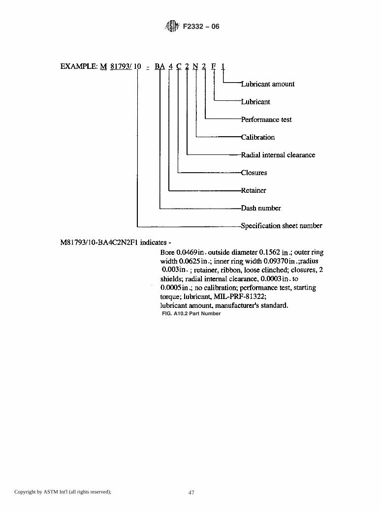
FIG. A10.2 Part Number
F2332 − 06
47Copyright by ASTM Int'l (all rights reserved);

A11. ANNULAR BALL BEARINGS FOR INSTRUMENTS AND PRECISION ROTATING COMPONENTS, DEEP GROOVE, UN-FLANGED, INNER RING EXTENDED, CORROSION-RESISTANT STEEL, ABEC 5P
A11.1 Requirements
A11.1.1 Design—All bearings described in this specifica-tion sheet shall be deep groove instrument bearings, unflanged,inner ring extended configuration (see Fig. A11.1).
A11.1.2 Material—The ball and ring material for thesebearings shall be corrosion-resistant steel 440C (UNS S44004)conforming to SAE-AMS-QQ-S-763.
A11.1.3 Tolerance Class— The tolerance class shall be inaccordance with the ABEC 5P tolerance tables of ABMAStandard 12.2. This tolerance class shall apply to all bearingsizes listed in Table A11.1.
A11.1.4 Boundary Dimensions—The boundary dimensionsshall be as specified by the dash number (Dash No.) in TableA11.1.
A11.1.5 Retainer—The retainer shall be as specified by thepart number designator (PN Des) in Table A11.2.
A11.1.6 Closures—The closures shall be as specified by thepart number designator in Table A11.3.
A11.1.7 Radial Internal Clearance —The radial internalclearance shall be as specified by the part number designator inTable A11.4.
A11.1.8 Calibration— The calibration shall be as specifiedby the part number designator in Table A11.5.
A11.1.9 Performance Test—The performance test shall beas specified by the part number designator in Table A11.6.
A11.1.10 Lubrication:
A11.1.10.1 Lubricant—The lubricant shall be in accordancewith the specification specified by the part number designatorin Table A11.7.
A11.1.10.2 Lubricant Amount—The amount of lubricantshall be as specified by the part number designator in TableA11.8.
A11.1.10.3 Barrier Coating— The barrier coating shall beapplied to bearings as specified by the part number designatorin Table A11.7.
A11.1.11 Part Number— The part number consists of thefollowing: prefix letter M; general specification number; num-ber of this specification sheet; dash number; and characters for:retainer, closures, radial internal clearance, calibration, perfor-mance test, lubricant, and lubricant amount (see Fig. A11.2).
FIG. A11.1 Bearing Configuration
F2332 − 06
48Copyright by ASTM Int'l (all rights reserved);

TABLE A11.1 Boundary Dimensions, inches
DashNo.
Bored
ODD
OuterRingWidth
C
InnerRingWidth
B
RadiusrA
-BA 0.0469 0.1562 0.0625 0.0937 0.003-BB 0.0469 0.1562 0.0937 0.1250 0.003-CA 0.0550 0.1875 0.0781 0.1094 0.003-CB 0.0550 0.1875 0.1094 0.1406 0.003-DA 0.0781 0.2500 0.0937 0.1250 0.003-DB 0.0781 0.2500 0.1406 0.1719 0.003-EA 0.0937 0.1875 0.0625 0.0937 0.003-EB 0.0937 0.1875 0.0937 0.1250 0.003-EC 0.0937 0.3125 0.1094 0.1406 0.003-ED 0.0937 0.3125 0.1406 0.1719 0.003-FA 0.1250 0.2500 0.0937 0.1250 0.003-FB 0.1250 0.2500 0.1094 0.1406 0.003-FC 0.1250 0.3125 0.1094 0.1406 0.003-FD 0.1250 0.3125 0.1406 0.1719 0.003-FE 0.1250 0.3750 0.1094 0.1406 0.003-FF 0.1250 0.3750 0.1406 0.1719 0.005-FG 0.1250 0.3750 0.1562 0.1875 0.012-GA 0.1562 0.3125 0.1094 0.1406 0.003-GB 0.1562 0.3125 0.1250 0.1562 0.003-HA 0.1875 0.3125 0.1094 0.1406 0.003-HB 0.1875 0.3125 0.1250 0.1562 0.003-HC 0.1875 0.3750 0.1250 0.1562 0.003-HD 0.1875 0.5000 0.1562 0.1875 0.012-HE 0.1875 0.5000 0.1960 0.2272 0.012-JA 0.2500 0.3750 0.1250 0.1562 0.003-JB 0.2500 0.5000 0.1250 0.1562 0.005-JC 0.2500 0.5000 0.1875 0.2188 0.005-JD 0.2500 0.6250 0.1960 0.2272 0.012-KA 0.3125 0.5000 0.1562 0.1875 0.003
A Maximum shaft or housing fillet radius that bearing corners will clear.
TABLE A11.2 Retainer
PN Des Type
0 no retainer, full complement1 manufacturer’s standardA
2 crownB
3 ribbon, tight-clinchedB
4 ribbon, loose-clinchedC
5 PTFE tube separatorD
7 phenolic laminateE ,F
8 vacuum-impregnated phenolicF ,G
9 nonporous, nonmetallic crownF
A One-piece pressed corrosion-resistant steel crown or two-piece pressedcorrosion-resistant steel ribbon.B One-piece pressed corrosion-resistant steel.C Two-piece pressed corrosion-resistant steel.D PTFE (polytetrafluoroethylene).E Phenolic or other porous nonmetallic material.F Used for high-speed applications.G Phenolic or other porous nonmetallic material saturated with lubricant. Selectionof this choice dictates choosing manufacturer’s standard amount of lubricant.
TABLE A11.3 Closures
PN Des Number Type
N none noneA one shieldA
C two shieldA
D one sealB
E one sealC
H two sealB
J two sealC
A Corrosion-resistant steel conforming to Specification A580/A580M, Condition A;Specification A240/A240M; Specification A756; or Specification A666 (for shield)and Specification A313/A313M, Type 302, Class 1, or SAE-AMS 5688 for snaprings.B Synthetic rubber.C Glass fiber (polytetrafluoroethylene) or other inert fiber.
TABLE A11.4 Radial Internal Clearance
PN Des Range, in.
1 0.0001 to 0.00032 0.0003 to 0.00055 0.0005 to 0.00088 0.0008 to 0.00119 As specified in contract
TABLE A11.5 Calibration of Bore and Outside Diameter (OD)
PN Des Bore Increments OD Increments
N no calibration no calibrationA no calibration 0.00010B no calibration 0.00005C 0.00010 no calibrationD 0.00010 0.00010E 0.00010 0.00005F 0.00005 no calibrationG 0.00005 0.00010H 0.00005 0.00005
F2332 − 06
49Copyright by ASTM Int'l (all rights reserved);

TABLE A11.6 Performance Test
PN Des Type
1 manufacturer’s standard2 starting torqueA
A Starting torque limits from Table 2 of base document.
TABLE A11.7 Lubricant
PN Des Specification
P preservativeA
A MIL-PRF-6085B MIL-PRF-6085B
C DOD-L-81846D DOD-L-81846B
E MIL-PRF-23827F MIL-PRF-81322G MIL-G-81937H MIL-PRF-83261J MIL-S-81087C
K MIL-S-81087C
L MIL-DTL-53131, Grade 4M MIL-DTL-53131, Grade 6N MIL-DTL-53131, Grade 9Q MIL-DTL-53131, Grade 14R MIL-DTL-53131, Grade 40S As specified in contract
A PN Des “P” shall be used only with PN Des “P” in Table A11.8.B With barrier coat.C Canceled – lube no longer manufactured.
TABLE A11.8 Lubricant Amount
PN Des Quantity
P preservative amount as required byMIL-DTL-197
1 manufacturer’s standardA
2 oil per Table 5 of base document3 15 % grease4 25 % grease5 35 % grease6 45 % grease7 As specified in contract
A Grease: fill to minimum 25 %, maximum 40 % of bearing void. Oil: immerse andthen allow excess to drip off. The standard quantity of oil varies with each bearingsize.
F2332 − 06
50Copyright by ASTM Int'l (all rights reserved);

FIG. A11.2 Part Number
F2332 − 06
51Copyright by ASTM Int'l (all rights reserved);

A12. ANNULAR BALL BEARINGS FOR INSTRUMENTS AND PRECISION ROTATING COMPONENTS, DEEP GROOVE, UN-FLANGED, INNER RING EXTENDED, CORROSIONRESISTANT STEEL, ABEC 7P
A12.1 Requirements
A12.1.1 Design—All bearings described in this specifica-tion sheet shall be deep groove instrument bearings, unflanged,inner ring extended configuration (see Fig. A12.1).
A12.1.2 Material—The ball and ring material for thesebearings shall be corrosion-resistant steel 440C (UNS S44004)conforming to SAE-AMS-QQ-S-763.
A12.1.3 Tolerance Class— The tolerance class shall be inaccordance with the ABEC 7P tolerance tables of ABMAStandard 12.2. This tolerance class shall apply to all bearingsizes listed in Table A12.1.
A12.1.4 Boundary Dimensions—The boundary dimensionsshall be as specified by the dash number (Dash No.) in TableA12.1.
A12.1.5 Retainer—The retainer shall be as specified by thepart number designator (PN Des) in Table A12.2.
A12.1.6 Closures—The closures shall be as specified by thepart number designator in Table A12.3.
A12.1.7 Radial Internal Clearance —The radial internalclearance shall be as specified by the part number designator inTable A12.4.
A12.1.8 Calibration— The calibration shall be as specifiedby the part number designator in Table A12.5.
A12.1.9 Performance Test—The performance test shall beas specified by the part number designator in Table A12.6.
A12.1.10 Lubrication:
A12.1.10.1 Lubricant—The lubricant shall be in accordancewith the specification specified by the part number designatorin Table A12.7.
A12.1.10.2 Lubricant Amount—The amount of lubricantshall be as specified by the part number designator in TableA12.8.
A12.1.10.3 Barrier Coating— The barrier coating shall beapplied to bearings as specified by the part number designatorin Table A12.7.
A12.1.11 Part Number— The part number consists of thefollowing: prefix letter M; general specification number; num-ber of this specification sheet; dash number; and characters for:retainer, closures, radial internal clearance, calibration, perfor-mance test, lubricant, and lubricant amount (see Fig. A12.2).
FIG. A12.1 Bearing Configuration
F2332 − 06
52Copyright by ASTM Int'l (all rights reserved);

TABLE A12.1 Boundary Dimensions, inches
DashNo.
Bored
ODD
OuterRingWidth
C
InnerRingWidth
B
RadiusrA
-BA 0.0469 0.1562 0.0625 0.0937 0.003-BB 0.0469 0.1562 0.0937 0.1250 0.003-CA 0.0550 0.1875 0.0781 0.1094 0.003-CB 0.0550 0.1875 0.1094 0.1406 0.003-DA 0.0781 0.2500 0.0937 0.1250 0.003-DB 0.0781 0.2500 0.1406 0.1719 0.003-EA 0.0937 0.1875 0.0625 0.0937 0.003-EB 0.0937 0.1875 0.0937 0.1250 0.003-EC 0.0937 0.3125 0.1094 0.1406 0.003-ED 0.0937 0.3125 0.1406 0.1719 0.003-FA 0.1250 0.2500 0.0937 0.1250 0.003-FB 0.1250 0.2500 0.1094 0.1406 0.003-FC 0.1250 0.3125 0.1094 0.1406 0.003-FD 0.1250 0.3125 0.1406 0.1719 0.003-FE 0.1250 0.3750 0.1094 0.1406 0.003-FF 0.1250 0.3750 0.1406 0.1719 0.005-FG 0.1250 0.3750 0.1562 0.1875 0.012-GA 0.1562 0.3125 0.1094 0.1406 0.003-GB 0.1562 0.3125 0.1250 0.1562 0.003-HA 0.1875 0.3125 0.1094 0.1406 0.003-HB 0.1875 0.3125 0.1250 0.1562 0.003-HC 0.1875 0.3750 0.1250 0.1562 0.003-HD 0.1875 0.5000 0.1562 0.1875 0.012-HE 0.1875 0.5000 0.1960 0.2272 0.012-JA 0.2500 0.3750 0.1250 0.1562 0.003-JB 0.2500 0.5000 0.1250 0.1562 0.005-JC 0.2500 0.5000 0.1875 0.2188 0.005-JD 0.2500 0.6250 0.1960 0.2272 0.012-KA 0.3125 0.5000 0.1562 0.1875 0.003
A Maximum shaft or housing fillet radius that bearing corners will clear.
TABLE A12.2 Retainer
PN Des Type
0 no retainer, full complement1 manufacturer’s standardA
2 crownB
3 ribbon, tight-clinchedB
4 ribbon, loose-clinchedC
5 PTFE tube separatorD
7 phenolic laminateE ,F
8 acuum-impregnated phenolicF ,G
9 nNonporous, nonmetallic crownF
A One-piece pressed corrosion-resistant steel crown or two-piece pressedcorrosion-resistant steel ribbon.B One-piece pressed corrosion-resistant steel.C Two-piece pressed corrosion-resistant steel.D PTFE (polytetrafluoroethylene).E Phenolic or other porous nonmetallic material.F Used for high-speed applications.G Phenolic or other porous nonmetallic material saturated with lubricant. Selectionof this choice dictates choosing manufacturer’s standard amount of lubricant.
TABLE A12.3 Closures
PN Des Number Type
N one noneA one shieldA
C two shieldA
D one sealB
E one sealC
H two sealB
J two sealC
A Corrosion-resistant steel conforming to Specification A580/A580M, Condition A;Specification A240/A240M; Specification A756; or Specification A666 (for shield)and Specification A313/A313M, Type 302, Class 1, or SAE-AMS 5688 for snaprings.B Synthetic rubber.C Glass fiber (polytetrafluoroethylene) or other inert fiber.
TABLE A12.4 Radial Internal Clearance
PN Des Range, in.
1 0.0001 to 0.00032 0.0003 to 0.00055 0.0005 to 0.00088 0.0008 to 0.00119 As specified in contract
TABLE A12.5 Calibration of Bore and Outside Diameter (OD)
PN Des Bore Increments OD Increments
N no calibration no calibrationA no calibration 0.00010B no calibration 0.00005C 0.00010 no calibrationD 0.00010 0.00010E 0.00010 0.00005F 0.00005 no calibrationG 0.00005 0.00010H 0.00005 0.00005
F2332 − 06
53Copyright by ASTM Int'l (all rights reserved);

TABLE A12.6 Performance Test
PN Des Type
1 manufacturer’s standard2 starting torqueA
A Starting torque limits from Table 2 of base document.
TABLE A12.7 Lubricant
PN Des Specification
P preservativeA
A MIL-PRF-6085B MIL-PRF-6085B
C DOD-L-81846D DOD-L-81846B
E MIL-PRF-23827F MIL-PRF-81322G MIL-G-81937H MIL-PRF-83261J MIL-S-81087C
K MIL-S-81087C
L MIL-DTL-53131, Grade 4M MIL-DTL-53131, Grade 6N MIL-DTL-53131, Grade 9Q MIL-DTL-53131, Grade 14R MIL-DTL-53131, Grade 40S As specified in contract
A PN Des “P” shall be used only with PN Des “P” in Table A12.8.B With barrier coat.C Canceled – lube no longer manufactured.
TABLE A12.8 Lubricant Amount
PN Des Quantity
P preservative amount as required byMIL-DTL-197
1 manufacturer’s standardA
2 oil per Table 5 of base document3 15 % grease4 25 % grease5 35 % grease6 45 % grease7 As specified in contract
A Grease: fill to minimum 25 %, maximum 40 % of bearing void. Oil: immerse andthen allow excess to drip off. The standard quantity of oil varies with each bearingsize.
F2332 − 06
54Copyright by ASTM Int'l (all rights reserved);

FIG. A12.2 Part Number
F2332 − 06
55Copyright by ASTM Int'l (all rights reserved);

A13. ANNULAR BALL BEARINGS FOR INSTRUMENTS AND PRECISION ROTATING COMPONENTS, DEEP GROOVE,FLANGED, INNER RING EXTENDED, CHROMIUM ALLOY STEEL, ABEC 5P
A13.1 Requirements
A13.1.1 Design—All bearings described in this specifica-tion sheet shall be deep groove instrument bearings, flanged,inner ring extended configuration (see Fig. A13.1).
A13.1.2 Material—The ball and ring material for thesebearings shall be chromium-alloy steel 52100 (UNS G52986)conforming to SAE-AMS 6444.
A13.1.3 Tolerance Class— The tolerance class shall be inaccordance with the ABEC 5P tolerance tables of ABMAStandard 12.2. This tolerance class shall apply to all bearingsizes listed in Table A13.1.
A13.1.4 Boundary Dimensions—The boundary dimensionsshall be as specified by the dash number (Dash No.) in TableA13.1.
A13.1.5 Retainer—The retainer shall be as specified by thepart number designator (PN Des) in Table A13.2.
A13.1.6 Closures—The closures shall be as specified by thepart number designator in Table A13.3.
A13.1.7 Radial Internal Clearance —The radial internalclearance shall be as specified by the part number designator inTable A13.4.
A13.1.8 Calibration— The calibration shall be as specifiedby the part number designator in Table A13.5.
A13.1.9 Performance Test—The performance test shall beas specified by the part number designator in Table A13.6.
A13.1.10 Lubrication:
A13.1.10.1 Lubricant—The lubricant shall be in accordancewith the specification specified by the part number designatorin Table A13.7.
A13.1.10.2 Lubricant Amount—The amount of lubricantshall be as specified by the part number designator in TableA13.8.
A13.1.10.3 Barrier Coating— The barrier coating shall beapplied to bearings as specified by the part number designatorin Table A13.7.
A13.1.11 Part Number— The part number consists of thefollowing: prefix letter M; general specification number; num-ber of this specification sheet; dash number; and characters for:retainer, closures, radial internal clearance, calibration, perfor-mance test, lubricant, and lubricant amount (see Fig. A13.2).
FIG. A13.1 Bearing Configuration
F2332 − 06
56Copyright by ASTM Int'l (all rights reserved);

TABLE A13.1 Boundary Dimensions, inches
DashNo.
Bored
RingODD
OuterRingWidth
C
InnerRingWidth
B
FlangeODD1
FlangeWidth
C1
RadiusrA
-BA 0.0469 0.1562 0.0625 0.0937 0.203 0.013 0.003-BB 0.0469 0.1562 0.0937 0.1250 0.203 0.031 0.003-CA 0.0550 0.1875 0.0781 0.1094 0.234 0.023 0.003-CB 0.0550 0.1875 0.1094 0.1406 0.234 0.031 0.003-DA 0.0781 0.2500 0.0937 0.1250 0.296 0.023 0.003-DB 0.0781 0.2500 0.1406 0.1719 0.296 0.031 0.003-EA 0.0937 0.1875 0.0625 0.0938 0.234 0.018 0.003-EB 0.0937 0.1875 0.0937 0.1250 0.234 0.031 0.003-EC 0.0937 0.3125 0.1094 0.1406 0.359 0.023 0.003-ED 0.0937 0.3125 0.1406 0.1719 0.234 0.031 0.003-FA 0.1250 0.2500 0.0937 0.1250 0.296 0.023 0.003-FB 0.1250 0.2500 0.1094 0.1406 0.296 0.031 0.003-FC 0.1250 0.3125 0.1094 0.1406 0.359 0.023 0.003-FD 0.1250 0.3125 0.1406 0.1719 0.359 0.031 0.003-FE 0.1250 0.3750 0.1094 0.1406 0.422 0.023 0.005-FF 0.1250 0.3750 0.1406 0.1719 0.422 0.031 0.005-FG 0.1250 0.3750 0.1562 0.1875 0.440 0.030 0.012-HA 0.1562 0.3125 0.1094 0.1406 0.359 0.023 0.003-HB 0.1562 0.3125 0.1250 0.1562 0.359 0.036 0.003-JA 0.1875 0.3125 0.1094 0.1406 0.359 0.023 0.003-JB 0.1875 0.3125 0.1250 0.1562 0.359 0.036 0.003-JC 0.1875 0.3750 0.1250 0.1562 0.422 0.023 0.003-JD 0.1875 0.3750 0.1250 0.1562 0.422 0.031 0.003-JE 0.1875 0.5000 0.1562 0.1875 0.565 0.042 0.012-JF 0.1875 0.5000 0.1960 0.2272 0.565 0.042 0.012-KA 0.2500 0.3750 0.1250 0.1562 0.422 0.023 0.003-KB 0.2500 0.3750 0.1250 0.1562 0.422 0.036 0.003-KC 0.2500 0.5000 0.1250 0.1562 0.547 0.023 0.005-KD 0.2500 0.5000 0.1875 0.2188 0.547 0.045 0.005-KE 0.2500 0.6250 0.1960 0.2272 0.690 0.042 0.012
A Maximum shaft or housing fillet radius that bearing corners will clear.
TABLE A13.2 Retainer
PN Des Type
0 no retainer, full complement1 manufacturer’s standardA
2 crownB
3 ribbon, tight-clinchedB
4 ribbon, loose-clinchedC
5 PTFE tube separatorD
7 phenolic laminateE ,F
8 vacuum-impregnated phenolicF ,G
9 nonporous, nonmetallic crownF
A One-piece pressed corrosion-resistant steel crown or two-piece pressedcorrosion-resistant steel ribbon.B One-piece pressed corrosion-resistant steel.C Two-piece pressed corrosion-resistant steel.D PTFE (polytetrafluoroethylene).E Phenolic or other porous nonmetallic material.F Used for high-speed applications.G Phenolic or other porous nonmetallic material saturated with lubricant. Selectionof this choice dictates choosing manufacturer’s standard amount of lubricant.
TABLE A13.3 Closures
PN Des Number Type Locations
N none noneA one shieldA normalB
B one shieldA oppositeC
C two shieldA
D one sealD normalB
E one sealE normalB
F one sealD oppositeC
G one sealE oppositeC
H two sealD
J two sealE
A Corrosion-resistant steel conforming to Specification A580/A580M, Condition A;Specification A240/A240M; Specification A756; or Specification A666 (for shield)and Specification A313/A313M, Type 302, Class 1, or SAE-AMS 5688 for snaprings.B On flange side.C On side opposite flange.D Synthetic rubber.E Glass fiber (polytetrafluoroethylene) or other inert fiber.
TABLE A13.4 Radial Internal Clearance
PN Des Range, in.
1 0.0001 to 0.00032 0.0003 to 0.00055 0.0005 to 0.00088 0.0008 to 0.00119 As specified in contract
TABLE A13.5 Calibration of Bore and Outside Diameter (OD)
PN Des Bore Increments OD Increments
N no calibration no calibrationA no calibration 0.00010B no calibration 0.00005C 0.00010 no calibrationD 0.00010 0.00010E 0.00010 0.00005F 0.00005 no calibrationG 0.00005 0.00010H 0.00005 0.00005
F2332 − 06
57Copyright by ASTM Int'l (all rights reserved);

TABLE A13.6 Performance Test
PN Des Type
1 manufacturer’s standard2 starting torqueA
A Starting torque limits from Table 2 of base document.
TABLE A13.7 Lubricant
PN Des Specification
P preservativeA
A MIL-PRF-6085B MIL-PRF-6085B
C DOD-L-81846D DOD-L-81846B
E MIL-PRF-23827F MIL-PRF-81322G MIL-G-81937H MIL-PRF-83261J MIL-S-81087C
K MIL-S-81087C
L MIL-DTL-53131, Grade 4M MIL-DTL-53131, Grade 6N MIL-DTL-53131, Grade 9Q MIL-DTL-53131, Grade 14R MIL-DTL-53131, Grade 40S As specified in contract
A PN Des “P” shall be used only with PN Des “P” in Table A13.8.B With barrier coat.C Canceled – lube no longer manufactured.
TABLE A13.8 Lubricant Amount
PN Des Quantity
P preservative amount as required byMIL-DTL-197
1 manufacturer’s standardA
2 oil per Table 5 of base document3 15 % grease4 25 % grease5 35 % grease6 45 % grease7 As specified in contract
A Grease: fill to minimum 25 %, maximum 40 % of bearing void. Oil: immerse andthen allow excess to drip off. The standard quantity of oil varies with each bearingsize.
F2332 − 06
58Copyright by ASTM Int'l (all rights reserved);

FIG. A13.2 Part Number
F2332 − 06
59Copyright by ASTM Int'l (all rights reserved);

A14. ANNULAR BALL BEARINGS FOR INSTRUMENTS AND PRECISION ROTATING COMPONENTS, DEEP GROOVE,FLANGED, INNER RING EXTENDED, CHROMIUM ALLOY STEEL, ABEC 7P
A14.1 Requirements
A14.1.1 Design—All bearings described in this specifica-tion sheet shall be deep groove instrument bearings, flanged,inner ring extended configuration (see Fig. A14.1).
A14.1.2 Material—The ball and ring material for thesebearings shall be chromium-alloy steel 52100 (UNS G52986)conforming to SAE-AMS 6444.
A14.1.3 Tolerance Class— The tolerance class shall be inaccordance with the ABEC 7P tolerance tables of ABMAStandard 12.2. This tolerance class shall apply to all bearingsizes listed in Table A14.1.
A14.1.4 Boundary Dimensions—The boundary dimensionsshall be as specified by the dash number (Dash No.) in TableA14.1.
A14.1.5 Retainer—The retainer shall be as specified by thepart number designator (PN Des) in Table A14.2.
A14.1.6 Closures—The closures shall be as specified by thepart number designator in Table A14.3.
A14.1.7 Radial Internal Clearance —The radial internalclearance shall be as specified by the part number designator inTable A14.4.
A14.1.8 Calibration— The calibration shall be as specifiedby the part number designator in Table A14.5.
A14.1.9 Performance Test—The performance test shall beas specified by the part number designator in Table A14.6.
A14.1.10 Lubrication:
A14.1.10.1 Lubricant—The lubricant shall be in accordancewith the specification specified by the part number designatorin Table A14.7.
A14.1.10.2 Lubricant Amount—The amount of lubricantshall be as specified by the part number designator in TableA14.8.
A14.1.10.3 Barrier Coating— The barrier coating shall beapplied to bearings as specified by the part number designatorin Table A14.7.
A14.1.11 Part Number— The part number consists of thefollowing: prefix letter M; general specification number; num-ber of this specification sheet; dash number; and characters for:retainer, closures, radial internal clearance, calibration, perfor-mance test, lubricant, and lubricant amount (see Fig. A14.2).
FIG. A14.1 Bearing Configuration
F2332 − 06
60Copyright by ASTM Int'l (all rights reserved);

TABLE A14.1 Boundary Dimensions, inches
DashNo.
Bored
RingODD
OuterRingWidth
C
InnerRingWidth
B
FlangeODD1
FlangeWidth
C1
RadiusrA
-BA 0.0469 0.1562 0.0625 0.0937 0.203 0.013 0.003-BB 0.0469 0.1562 0.0937 0.1250 0.203 0.031 0.003-CA 0.0550 0.1875 0.0781 0.1094 0.234 0.023 0.003-CB 0.0550 0.1875 0.1094 0.1406 0.234 0.031 0.003-DA 0.0781 0.2500 0.0937 0.1250 0.296 0.023 0.003-DB 0.0781 0.2500 0.1406 0.1719 0.296 0.031 0.003-EA 0.0937 0.1875 0.0625 0.0938 0.234 0.018 0.003-EB 0.0937 0.1875 0.0937 0.1250 0.234 0.031 0.003-EC 0.0937 0.3125 0.1094 0.1406 0.359 0.023 0.003-ED 0.0937 0.3125 0.1406 0.1719 0.234 0.031 0.003-FA 0.1250 0.2500 0.0937 0.1250 0.296 0.023 0.003-FB 0.1250 0.2500 0.1094 0.1406 0.296 0.031 0.003-FC 0.1250 0.3125 0.1094 0.1406 0.359 0.023 0.003-FD 0.1250 0.3125 0.1406 0.1719 0.359 0.031 0.003-FE 0.1250 0.3750 0.1094 0.1406 0.422 0.023 0.005-FF 0.1250 0.3750 0.1406 0.1719 0.422 0.031 0.005-FG 0.1250 0.3750 0.1562 0.1875 0.440 0.030 0.012-HA 0.1562 0.3125 0.1094 0.1406 0.359 0.023 0.003-HB 0.1562 0.3125 0.1250 0.1562 0.359 0.036 0.003-JA 0.1875 0.3125 0.1094 0.1406 0.359 0.023 0.003-JB 0.1875 0.3125 0.1250 0.1562 0.359 0.036 0.003-JC 0.1875 0.3750 0.1250 0.1562 0.422 0.023 0.003-JD 0.1875 0.3750 0.1250 0.1562 0.422 0.031 0.003-JE 0.1875 0.5000 0.1562 0.1875 0.565 0.042 0.012-JF 0.1875 0.5000 0.1960 0.2272 0.565 0.042 0.012-KA 0.2500 0.3750 0.1250 0.1562 0.422 0.023 0.003-KB 0.2500 0.3750 0.1250 0.1562 0.422 0.036 0.003-KC 0.2500 0.5000 0.1250 0.1562 0.547 0.023 0.005-KD 0.2500 0.5000 0.1875 0.2188 0.547 0.045 0.005-KE 0.2500 0.6250 0.1960 0.2272 0.690 0.042 0.012
A Maximum shaft or housing fillet radius that bearing corners will clear.
TABLE A14.2 Retainer
PN Des Type
0 no retainer, full complement1 manufacturer’s standardA
2 crownB
3 ribbon, tight-clinchedB
4 ribbon, loose-clinchedC
5 PTFE tube separatorD
7 phenolic laminateE ,F
8 vacuum-impregnated phenolicF ,G
9 nonporous, nonmetallic crownF
A One-piece pressed corrosion-resistant steel crown or two-piece pressedcorrosion-resistant steel ribbon.B One-piece pressed corrosion-resistant steel.C Two-piece pressed corrosion-resistant steel.D PTFE (polytetrafluoroethylene).E Phenolic or other porous nonmetallic material.F Used for high-speed applications.G Phenolic or other porous nonmetallic material saturated with lubricant. Selectionof this choice dictates choosing manufacturer’s standard amount of lubricant.
TABLE A14.3 Closures
PN Des Number Type Locations
N none noneA one shieldA normalB
B one shieldA oppositeC
C two shieldA
D one sealD normalB
E one sealE normalB
F one sealD oppositeC
G one sealE oppositeC
H two sealD
J two sealE
A Corrosion-resistant steel conforming to Specification A580/A580M, Condition A;Specification A240/A240M; Specification A756; or Specification A666 (for shield)and Specification A313/A313M, Type 302, Class 1, or SAE-AMS 5688 for snaprings.B On flange side.C On side opposite flange.D Synthetic rubber.E Glass fiber (polytetrafluoroethylene) or other inert fiber.
TABLE A14.4 Radial Internal Clearance
PN Des Range, in.
1 0.0001 to 0.00032 0.0003 to 0.00055 0.0005 to 0.00088 0.0008 to 0.00119 As specified in contract
TABLE A14.5 Calibration of Bore and Outside Diameter (OD)
PN Des Bore Increments OD Increments
N no calibration no calibrationA no calibration 0.00010B no calibration 0.00005C 0.00010 no calibrationD 0.00010 0.00010E 0.00010 0.00005F 0.00005 no calibrationG 0.00005 0.00010H 0.00005 0.00005
F2332 − 06
61Copyright by ASTM Int'l (all rights reserved);

TABLE A14.6 Performance Test
PN Des Type
1 manufacturer’s standard2 starting torqueA
A Starting torque limits from Table 2 of base document.
TABLE A14.7 Lubricant
PN Des Specification
P preservativeA
A MIL-PRF-6085B MIL-PRF-6085B
C DOD-L-81846D DOD-L-81846B
E MIL-PRF-23827F MIL-PRF-81322G MIL-G-81937H MIL-PRF-83261J MIL-S-81087C
K MIL-S-81087C
L MIL-DTL-53131, Grade 4M MIL-DTL-53131, Grade 6N MIL-DTL-53131, Grade 9Q MIL-DTL-53131, Grade 14R MIL-DTL-53131, Grade 40S As specified in contract
A PN Des “P” shall be used only with PN Des “P” in Table A14.8.B With barrier coat.C Canceled – lube no longer manufactured.
TABLE A14.8 Lubricant Amount
PN Des Quantity
P preservative amount as required byMIL-DTL-197
1 manufacturer’s standardA
2 oil per Table 5 of base document3 15 % grease4 25 % grease5 35 % grease6 45 % grease7 As specified in contract
A Grease: fill to minimum 25 %, maximum 40 % of bearing void. Oil: immerse andthen allow excess to drip off. The standard quantity of oil varies with each bearingsize.
F2332 − 06
62Copyright by ASTM Int'l (all rights reserved);

FIG. A14.2 Part Number
F2332 − 06
63Copyright by ASTM Int'l (all rights reserved);

A15. ANNULAR BALL BEARINGS FOR INSTRUMENTS AND PRECISION ROTATING COMPONENTS, DEEP GROOVE,FLANGED, INNER RING EXTENDED, CORROSION RESISTANT STEEL, ABEC 5P
A15.1 Requirements
A15.1.1 Design—All bearings described in this specifica-tion sheet shall be deep groove instrument bearings, flanged,inner ring extended configuration (see Fig. A15.1).
A15.1.2 Material—The ball and ring material for thesebearings shall be corrosion-resistant steel 440C (UNS S44004)conforming to SAE-AMS-QQ-S-763.
A15.1.3 Tolerance Class— The tolerance class shall be inaccordance with the ABEC 5P tolerance tables of ABMAStandard 12.2. This tolerance class shall apply to all bearingsizes listed in Table A15.1.
A15.1.4 Boundary Dimensions—The boundary dimensionsshall be as specified by the dash number (Dash No.) in TableA15.1.
A15.1.5 Retainer—The retainer shall be as specified by thepart number designator (PN Des) in Table A15.2.
A15.1.6 Closures—The closures shall be as specified by thepart number designator in Table A15.3.
A15.1.7 Radial Internal Clearance —The radial internalclearance shall be as specified by the part number designator inTable A15.4.
A15.1.8 Calibration— The calibration shall be as specifiedby the part number designator in Table A15.5.
A15.1.9 Performance Test—The performance test shall beas specified by the part number designator in Table A15.6.
A15.1.10 Lubrication:
A15.1.10.1 Lubricant—The lubricant shall be in accordancewith the specification specified by the part number designatorin Table A15.7.
A15.1.10.2 Lubricant Amount—The amount of lubricantshall be as specified by the part number designator in TableA15.8.
A15.1.10.3 Barrier Coating— The barrier coating shall beapplied to bearings as specified by the part number designatorin Table A15.7.
A15.1.11 Part Number— The part number consists of thefollowing: prefix letter M; general specification number; num-ber of this specification sheet; dash number; and characters for:retainer, closures, radial internal clearance, calibration, perfor-mance test, lubricant, and lubricant amount (see Fig. A15.2).
FIG. A15.1 Bearing Configuration
F2332 − 06
64Copyright by ASTM Int'l (all rights reserved);

TABLE A15.1 Boundary Dimensions, inches
DashNo.
Bored
RingODD
OuterRingWidth
C
InnerRingWidth
B
FlangeODD1
FlangeWidth
C1
RadiusrA
-BA 0.0469 0.1562 0.0625 0.0937 0.203 0.013 0.003-BB 0.0469 0.1562 0.0937 0.1250 0.203 0.031 0.003-CA 0.0550 0.1875 0.0781 0.1094 0.234 0.023 0.003-CB 0.0550 0.1875 0.1094 0.1406 0.234 0.031 0.003-DA 0.0781 0.2500 0.0937 0.1250 0.296 0.023 0.003-DB 0.0781 0.2500 0.1406 0.1719 0.296 0.031 0.003-EA 0.0937 0.1875 0.0625 0.0938 0.234 0.018 0.003-EB 0.0937 0.1875 0.0937 0.1250 0.234 0.031 0.003-EC 0.0937 0.3125 0.1094 0.1406 0.359 0.023 0.003-ED 0.0937 0.3125 0.1406 0.1719 0.234 0.031 0.003-FA 0.1250 0.2500 0.0937 0.1250 0.296 0.023 0.003-FB 0.1250 0.2500 0.1094 0.1406 0.296 0.031 0.003-FC 0.1250 0.3125 0.1094 0.1406 0.359 0.023 0.003-FD 0.1250 0.3125 0.1406 0.1719 0.359 0.031 0.003-FE 0.1250 0.3750 0.1094 0.1406 0.422 0.023 0.005-FF 0.1250 0.3750 0.1406 0.1719 0.422 0.031 0.005-FG 0.1250 0.3750 0.1562 0.1875 0.440 0.030 0.012-HA 0.1562 0.3125 0.1094 0.1406 0.359 0.023 0.003-HB 0.1562 0.3125 0.1250 0.1562 0.359 0.036 0.003-JA 0.1875 0.3125 0.1094 0.1406 0.359 0.023 0.003-JB 0.1875 0.3125 0.1250 0.1562 0.359 0.036 0.003-JC 0.1875 0.3750 0.1250 0.1562 0.422 0.023 0.003-JD 0.1875 0.3750 0.1250 0.1562 0.422 0.031 0.003-JE 0.1875 0.5000 0.1562 0.1875 0.565 0.042 0.012-JF 0.1875 0.5000 0.1960 0.2272 0.565 0.042 0.012-KA 0.2500 0.3750 0.1250 0.1562 0.422 0.023 0.003-KB 0.2500 0.3750 0.1250 0.1562 0.422 0.036 0.003-KC 0.2500 0.5000 0.1250 0.1562 0.547 0.023 0.005-KD 0.2500 0.5000 0.1875 0.2188 0.547 0.045 0.005-KE 0.2500 0.6250 0.1960 0.2272 0.690 0.042 0.012
A Maximum shaft or housing fillet radius that bearing corners will clear.
TABLE A15.2 Retainer
PN Des Type
0 no retainer, full complement1 manufacturer’s standardA
2 crownB
3 ribbon, tight-clinchedB
4 ribbon, loose-clinchedC
5 PTFE tube separatorD
7 phenolic laminateE ,F
8 vacuum-impregnated phenolicF ,G
9 nonporous, nonmetallic crownF
A One-piece pressed corrosion-resistant steel crown or two-piece pressedcorrosion-resistant steel ribbon.B One-piece pressed corrosion-resistant steel.C Two-piece pressed corrosion-resistant steel.D PTFE (polytetrafluoroethylene).E Phenolic or other porous nonmetallic material.F Used for high-speed applications.G Phenolic or other porous nonmetallic material saturated with lubricant. Selectionof this choice dictates choosing manufacturer’s standard amount of lubricant.
TABLE A15.3 Closures
PN Des Number Type Locations
N none noneA one shieldA normalB
B one shieldA oppositeC
C two shieldA
D one sealD normalB
E one sealE normalB
F one sealD oppositeC
G one sealE oppositeC
H two sealD
J two sealE
A Corrosion-resistant steel conforming to Specification A580/A580M, Condition A;Specification A240/A240M; Specification A756; or Specification A666 (for shield)and Specification A313/A313M, Type 302, Class 1, or SAE-AMS 5688 for snaprings.B On flange side.C On side opposite flange.D Synthetic rubber.E Glass fiber (polytetrafluoroethylene) or other inert fiber.
TABLE A15.4 Radial Internal Clearance
PN Des Range, in.
1 0.0001 to 0.00032 0.0003 to 0.00055 0.0005 to 0.00088 0.0008 to 0.00119 As specified in contract
TABLE A15.5 Calibration of Bore and Outside Diameter (OD)
PN Des Bore Increments OD Increments
N no calibration no calibrationA no calibration 0.00010B no calibration 0.00005C 0.00010 no calibrationD 0.00010 0.00010E 0.00010 0.00005F 0.00005 no calibrationG 0.00005 0.00010H 0.00005 0.00005
F2332 − 06
65Copyright by ASTM Int'l (all rights reserved);

TABLE A15.6 Performance Test
PN Des Type
1 manufacturer’s standard2 starting torqueA
A Starting torque limits from Table 2 of base document.
TABLE A15.7 Lubricant
PN Des Specification
P preservativeA
A MIL-PRF-6085B MIL-PRF-6085B
C DOD-L-81846D DOD-L-81846B
E MIL-PRF-23827F MIL-PRF-81322G MIL-G-81937H MIL-PRF-83261J MIL-S-81087C
K MIL-S-81087C
L MIL-DTL-53131, Grade 4M MIL-DTL-53131, Grade 6N MIL-DTL-53131, Grade 9Q MIL-DTL-53131, Grade 14R MIL-DTL-53131, Grade 40S As specified in contract
A PN Des “P” shall be used only with PN Des “P” in Table A15.8.B With barrier coat.C Canceled – lube no longer manufactured.
TABLE A15.8 Lubricant Amount
PN Des Quantity
P preservative amount as required byMIL-DTL-197
1 manufacturer’s standardA
2 oil per Table 5 of base document3 15 % grease4 25 % grease5 35 % grease6 45 % grease7 As specified in contract
A Grease: fill to minimum 25 %, maximum 40 % of bearing void. Oil: immerse andthen allow excess to drip off. The standard quantity of oil varies with each bearingsize.
F2332 − 06
66Copyright by ASTM Int'l (all rights reserved);

FIG. A15.2 Part Number
F2332 − 06
67Copyright by ASTM Int'l (all rights reserved);

A16. ANNULAR BALL BEARINGS FOR INSTRUMENTS AND PRECISION ROTATING COMPONENTS, DEEP GROOVE,FLANGED, INNER RING EXTENDED, CORROSION RESISTANT STEEL, ABEC 7P
A16.1 Requirements
A16.1.1 Design—All bearings described in this specifica-tion sheet shall be deep groove instrument bearings, flanged,inner ring extended configuration (see Fig. A16.1).
A16.1.2 Material—The ball and ring material for thesebearings shall be corrosion-resistant steel 440C (UNS S44004)conforming to SAE-AMS-QQ-S-763.
A16.1.3 Tolerance Class— The tolerance class shall be inaccordance with the ABEC 7P tolerance tables of ABMAStandard 12.2. This tolerance class shall apply to all bearingsizes listed in Table A16.1.
A16.1.4 Boundary Dimensions—The boundary dimensionsshall be as specified by the dash number (Dash No.) in TableA16.1.
A16.1.5 Retainer—The retainer shall be as specified by thepart number designator (PN Des) in Table A16.2.
A16.1.6 Closures—The closures shall be as specified by thepart number designator in Table A16.3.
A16.1.7 Radial Internal Clearance —The radial internalclearance shall be as specified by the part number designator inTable A16.4.
A16.1.8 Calibration— The calibration shall be as specifiedby the part number designator in Table A16.5.
A16.1.9 Performance Test—The performance test shall beas specified by the part number designator in Table A16.6.
A16.1.10 Lubrication:
A16.1.10.1 Lubricant—The lubricant shall be in accordancewith the specification specified by the part number designatorin Table A16.7.
A16.1.10.2 Lubricant Amount—The amount of lubricantshall be as specified by the part number designator in TableA16.8.
A16.1.10.3 Barrier Coating— The barrier coating shall beapplied to bearings as specified by the part number designatorin Table A16.7.
A16.1.11 Part Number— The part number consists of thefollowing: prefix letter M; general specification number; num-ber of this specification sheet; dash number; and characters for:retainer, closures, radial internal clearance, calibration, perfor-mance test, lubricant, and lubricant amount (see Fig. A16.2).
FIG. A16.1 Bearing Configuration
F2332 − 06
68Copyright by ASTM Int'l (all rights reserved);

TABLE A16.1 Boundary Dimensions, inches
DashNo.
Bored
RingODD
OuterRingWidth
C
InnerRingWidth
B
FlangeODD1
FlangeWidth
C1
RadiusrA
-BA 0.0469 0.1562 0.0625 0.0937 0.203 0.013 0.003-BB 0.0469 0.1562 0.0937 0.1250 0.203 0.031 0.003-CA 0.0550 0.1875 0.0781 0.1094 0.234 0.023 0.003-CB 0.0550 0.1875 0.1094 0.1406 0.234 0.031 0.003-DA 0.0781 0.2500 0.0937 0.1250 0.296 0.023 0.003-DB 0.0781 0.2500 0.1406 0.1719 0.296 0.031 0.003-EA 0.0937 0.1875 0.0625 0.0938 0.234 0.018 0.003-EB 0.0937 0.1875 0.0937 0.1250 0.234 0.031 0.003-EC 0.0937 0.3125 0.1094 0.1406 0.359 0.023 0.003-ED 0.0937 0.3125 0.1406 0.1719 0.234 0.031 0.003-FA 0.1250 0.2500 0.0937 0.1250 0.296 0.023 0.003-FB 0.1250 0.2500 0.1094 0.1406 0.296 0.031 0.003-FC 0.1250 0.3125 0.1094 0.1406 0.359 0.023 0.003-FD 0.1250 0.3125 0.1406 0.1719 0.359 0.031 0.003-FE 0.1250 0.3750 0.1094 0.1406 0.422 0.023 0.005-FF 0.1250 0.3750 0.1406 0.1719 0.422 0.031 0.005-FG 0.1250 0.3750 0.1562 0.1875 0.440 0.030 0.012-HA 0.1562 0.3125 0.1094 0.1406 0.359 0.023 0.003-HB 0.1562 0.3125 0.1250 0.1562 0.359 0.036 0.003-JA 0.1875 0.3125 0.1094 0.1406 0.359 0.023 0.003-JB 0.1875 0.3125 0.1250 0.1562 0.359 0.036 0.003-JC 0.1875 0.3750 0.1250 0.1562 0.422 0.023 0.003-JD 0.1875 0.3750 0.1250 0.1562 0.422 0.031 0.003-JE 0.1875 0.5000 0.1562 0.1875 0.565 0.042 0.012-JF 0.1875 0.5000 0.1960 0.2272 0.565 0.042 0.012-KA 0.2500 0.3750 0.1250 0.1562 0.422 0.023 0.003-KB 0.2500 0.3750 0.1250 0.1562 0.422 0.036 0.003-KC 0.2500 0.5000 0.1250 0.1562 0.547 0.023 0.005-KD 0.2500 0.5000 0.1875 0.2188 0.547 0.045 0.005-KE 0.2500 0.6250 0.1960 0.2272 0.690 0.042 0.012
A Maximum shaft or housing fillet radius that bearing corners will clear.
TABLE A16.2 Retainer
PN Des Type
0 no retainer, full complement1 manufacturer’s standardA
2 crownB
3 ribbon, tight-clinchedB
4 ribbon, loose-clinchedC
5 PTFE tube separatorD
7 phenolic laminateE ,F
8 vacuum-impregnated phenolicF ,G
9 nonporous, nonmetallic crownF
A One-piece pressed corrosion-resistant steel crown or two-piece pressedcorrosion-resistant steel ribbon.B One-piece pressed corrosion-resistant steel.C Two-piece pressed corrosion-resistant steel.D PTFE (polytetrafluoroethylene).E Phenolic or other porous nonmetallic material.F Used for high-speed applications.G Phenolic or other porous nonmetallic material saturated with lubricant. Selectionof this choice dictates choosing manufacturer’s standard amount of lubricant.
TABLE A16.3 Closures
PN Des Number Type Locations
N none noneA one shieldA normalB
B one shieldA oppositeC
C two shieldA
D one sealD normalB
E one sealE normalB
F one sealD oppositeC
G one sealE oppositeC
H two sealD
J two sealE
A Corrosion-resistant steel conforming to Specification A580/A580M, Condition A;Specification A240/A240M; Specification A756; or Specification A666 (for shield)and Specification A313/A313M, Type 302, Class 1, or SAE-AMS 5688 for snaprings.B On flange side.C On side opposite flange.D Synthetic rubber.E Glass fiber (polytetrafluoroethylene) or other inert fiber.
TABLE A16.4 Radial Internal Clearance
PN Des Range, in.
1 0.0001 to 0.00032 0.0003 to 0.00055 0.0005 to 0.00088 0.0008 to 0.00119 As specified in contract
TABLE A16.5 Calibration of Bore and Outside Diameter (OD)
PN Des Bore Increments OD Increments
N no calibration no calibrationA no calibration 0.00010B no calibration 0.00005C 0.00010 no calibrationD 0.00010 0.00010E 0.00010 0.00005F 0.00005 no calibrationG 0.00005 0.00010H 0.00005 0.00005
F2332 − 06
69Copyright by ASTM Int'l (all rights reserved);

TABLE A16.6 Performance Test
PN Des Type
1 manufacturer’s standard2 starting torqueA
A Starting torque limits from Table 2 of base document.
TABLE A16.7 Lubricant
PN Des Specification
P preservativeA
A MIL-PRF-6085B MIL-PRF-6085B
C DOD-L-81846D DOD-L-81846B
E MIL-PRF-23827F MIL-PRF-81322G MIL-G-81937H MIL-PRF-83261J MIL-S-81087C
K MIL-S-81087C
L MIL-DTL-53131, Grade 4M MIL-DTL-53131, Grade 6N MIL-DTL-53131, Grade 9Q MIL-DTL-53131, Grade 14R MIL-DTL-53131, Grade 40S As specified in contract
A PN Des “P” shall be used only with PN Des “P” in Table A16.8.B With barrier coat.C Canceled – lube no longer manufactured.
TABLE A16.8 Lubricant Amount
PN Des Quantity
P preservative amount as required byMIL-DTL-197
1 manufacturer’s standardA
2 oil per Table 5 of base document3 15 % grease4 25 % grease5 35 % grease6 45 % grease7 As specified in contract
A Grease: fill to minimum 25 %, maximum 40 % of bearing void. Oil: immerse andthen allow excess to drip off. The standard quantity of oil varies with each bearingsize.
F2332 − 06
70Copyright by ASTM Int'l (all rights reserved);

FIG. A16.2 Part Number
F2332 − 06
71Copyright by ASTM Int'l (all rights reserved);

A17. ANNULAR BALL BEARINGS FOR INSTRUMENTS AND PRECISION ROTATING COMPONENTS, ANGULAR CON-TACT, UNFLANGED, NONSEPARABLE, AND COUNTERBORED OUTER RING, CHROMIUM ALLOY STEEL, ABEC 5P
A17.1 Requirements
A17.1.1 Design—All bearings described in this specifica-tion sheet shall be angular contact instrument bearings, unf-langed, nonseparable, and counterbored outer ring configura-tion (see Fig. A17.1).
A17.1.2 Material—The ball and ring material for thesebearings shall be chromium-alloy steel 52100 (UNS G52986)conforming to SAE-AMS 6444.
A17.1.3 Tolerance Class— The tolerance class shall be inaccordance with the ABEC 5P tolerance tables of ABMAStandard 12.2. This tolerance class shall apply to all bearingsizes listed in Table A17.1.
A17.1.4 Boundary Dimensions—The boundary dimensionsshall be as specified by the dash number (Dash No.) in TableA17.1.
A17.1.5 Retainer—The retainer shall be as specified by thepart number designator (PN Des) in Table A17.2.
A17.1.6 Closures—The closures shall be as specified by thepart number designator in Table A17.3.
A17.1.7 Radial Internal Clearance —The radial internalclearance shall be as specified by the part number designator inTable A17.4.
A17.1.8 Calibration— The calibration shall be as specifiedby the part number designator in Table A17.5.
A17.1.9 Performance Test—The performance test shall beas specified by the part number designator in Table A17.6.
A17.1.10 Lubrication:
A17.1.10.1 Lubricant—The lubricant shall be in accordancewith the specification specified by the part number designatorin Table A17.7.
A17.1.10.2 Lubricant Amount—The amount of lubricantshall be as specified by the part number designator in TableA17.8.
A17.1.10.3 Barrier Coating— The barrier coating shall beapplied to bearings as specified by the part number designatorin Table A17.7.
A17.1.11 Part Number— The part number consists of thefollowing: prefix letter M; general specification number; num-ber of this specification sheet; dash number; and characters for:retainer, closures, radial internal clearance, calibration, perfor-mance test, lubricant, and lubricant amount (see Fig. A17.2).
FIG. A17.1 Bearing Configuration
F2332 − 06
72Copyright by ASTM Int'l (all rights reserved);

TABLE A17.1 Boundary Dimensions, inches
DashNo.
Bored
ODD
WidthC
RadiusrA,B
-AA 0.0400 0.1250 0.0469 0.003-BA 0.0469 0.1562 0.0625 0.003-BC 0.0469 0.1562 0.0937 0.003-CA 0.0550 0.1875 0.0781 0.003-CB 0.0550 0.1875 0.1094 0.003-DA 0.0781 0.2500 0.0937 0.003-DB 0.0781 0.2500 0.1406 0.003-DC 0.0781 0.2500 0.1094 0.003-EA 0.0937 0.1875 0.0625 0.003-EB 0.0937 0.1875 0.0937 0.003-EC 0.0937 0.2500 0.0625 0.003-ED 0.0937 0.2500 0.0937 0.003-EE 0.0937 0.2500 0.1094 0.003-EF 0.0937 0.2883 0.0625 0.003-KG 0.0937 0.3125 0.0625 0.003-EH 0.0937 0.3125 0.1094 0.003-EJ 0.0937 0.3125 0.1406 0.003-EK 0.0937 0.4100 0.1094 0.003-FA 0.1250 0.2500 0.0937 0.003-FB 0.1250 0.2500 0.1094 0.003-FC 0.1250 0.3125 0.1094 0.003-FD 0.1250 0.3125 0.1406 0.003-FE 0.1250 0.3750 0.1094 0.005-FF 0.1250 0.3750 0.1406 0.005-FG 0.1250 0.3750 0.1562 0.012-FH 0.1250 0.4100 0.0937 0.003-FJ 0.1250 0.4100 0.1094 0.003-FK 0.1250 0.4250 0.0937 0.003-FL 0.1250 0.4250 0.1094 0.003-FM 0.1250 0.4375 0.1094 0.003-FN 0.1250 0.4375 0.1406 0.003-FP 0.1250 0.5000 0.1094 0.003-FR 0.1250 0.5000 0.1719 0.012-FT 0.1250 0.7500 0.1250 0.010-FV 0.1250 0.3750 0.0937 0.003-GA 0.1562 0.3125 0.1094 0.003-GB 0.1562 0.3125 0.1250 0.003-HA 0.1875 0.3125 0.1094 0.003-HB 0.1875 0.3125 0.1250 0.003-HC 0.1875 0.3750 0.1094 0.003-HD 0.1875 0.3750 0.1250 0.003-HE 0.1875 0.4100 0.1094 0.003-HF 0.1875 0.4250 0.1094 0.003-HG 0.1875 0.4375 0.1094 0.003-HH 0.1875 0.5000 0.1094 0.003-HJ 0.1875 0.5000 0.1562 0.012-HK 0.1875 0.5000 0.1960 0.012-HL 0.1875 0.7435 0.1960 0.012-HM 0.1875 0.7500 0.1960 0.012-HN 0.1875 0.8750 0.1960 0.012-JA 0.2500 0.3750 0.1250 0.003-JB 0.2500 0.5000 0.1094 0.003-JC 0.2500 0.5000 0.1250 0.005-JD 0.2500 0.5000 0.1875 0.005-JE 0.2500 0.6250 0.1960 0.012-JF 0.2500 0.7500 0.1960 0.012-JG 0.2500 0.7500 0.2188 0.016-JH 0.2500 0.7500 0.2812 0.016-JJ 0.2500 0.8750 0.1960 0.012-JK 0.2500 1.0000 0.1960 0.012-JL 0.2500 1.0480 0.1960 0.012-KA 0.3125 0.5000 0.1562 0.005-KB 0.3125 0.6250 0.1562 0.010-LA 0.3750 0.8750 0.2188 0.016-LB 0.3750 0.8750 0.2812 0.016-MA 0.5000 0.8750 0.2188 0.016-MB 0.5000 0.8750 0.2812 0.016-MC 0.5000 1.1250 0.2500 0.016-MD 0.5000 1.1250 0.3125 0.016-NA 0.6250 1.3750 0.2812 0.031-NB 0.6250 1.3750 0.3438 0.031
A Maximum shaft or housing fillet radius that bearing corners will clear.B Narrow face of rings shall have a maximum r value of one half the value listedprovided this quantity does not fall below 0.003 inches.
TABLE A17.2 Retainer
PN Des Type
0 no retainer, full complement6 PTFE toroidsA
7 phenolic laminateB ,C
8 vacuum-impregnated phenolicC ,D
9 nonporous, nonmetallicC
A PTFE (polytetrafluoroethylene).B Phenolic or other porous non-metallic material.C Used for high-speed applications.D Phenolic or other porous nonmetallic material saturated with lubricant. Selectionof this choice dictates choosing manufacturer’s standard amount of lubricant.
TABLE A17.3 Closures
PN Des Number Type
N none none
TABLE A17.4 Radial Internal Clearance or Contact Angle
PN Des Range
1 0.0001 to 0.0003 in.2 0.0003 to 0.0005 in.3 14° or lessA
4 greater than 14° but less than 20°A
5 0.0005 to 0.0008 in.6 greater than 20°A
8 0.0008 to 0.0011 in.9 As specified in contract
A Angular contact bearing designations only.
TABLE A17.5 Calibration of Bore and Outside Diameter (OD)
PN Des Bore Increments OD Increments
N no calibration no calibrationA no calibration 0.00010B no calibration 0.00005C 0.00010 no calibrationD 0.00010 0.00010E 0.00010 0.00005F 0.00005 no calibrationG 0.00005 0.00010H 0.00005 0.00005
F2332 − 06
73Copyright by ASTM Int'l (all rights reserved);

TABLE A17.6 Performance Test
PN Des Type
1 manufacturer’s standard2 starting torqueA
A Starting torque limits from Table 2 of base document.
TABLE A17.7 Lubricant
PN Des Specification
P preservativeA
A MIL-PRF-6085B MIL-PRF-6085B
C DOD-L-81846D DOD-L-81846B
E MIL-PRF-23827F MIL-PRF-81322G MIL-G-81937H MIL-PRF-83261J MIL-S-81087C
K MIL-S-81087C
L MIL-DTL-53131, Grade 4M MIL-DTL-53131, Grade 6N MIL-DTL-53131, Grade 9Q MIL-DTL-53131, Grade 14R MIL-DTL-53131, Grade 40S As specified in the contract
A PN Des “P” shall be used only with PN Des “P” in Table A17.8.B With barrier coat.C Canceled – lube no longer manufactured.
TABLE A17.8 Lubricant Amount
PN Des Quantity
P preservative amount as required byMIL-DTL-197
1 manufacturer’s standardA
2 oil per Table 5 of base document3 15 % grease4 25 % grease5 35 % grease6 45 % grease7 As specified in contract
A Grease: fill to minimum 25 %, maximum 40 % of bearing void. Oil: immerse andthen allow excess to drip off. The standard quantity of oil varies with each bearingsize.
F2332 − 06
74Copyright by ASTM Int'l (all rights reserved);

FIG. A17.2 Part Number
F2332 − 06
75Copyright by ASTM Int'l (all rights reserved);

A18. ANNULAR BALL BEARINGS FOR INSTRUMENTS AND PRECISION ROTATING COMPONENTS, ANGULAR CON-TACT, UNFLANGED, NONSEPARABLE, AND COUNTERBORED OUTER RING, CHROMIUM ALLOY STEEL, ABEC 7P
A18.1 Requirements
A18.1.1 Design—All bearings described in this specifica-tion sheet shall be angular contact instrument bearings, unf-langed, nonseparable, and counterbored outer ring configura-tion (see Fig. A18.1).
A18.1.2 Material—The ball and ring material for thesebearings shall be chromium-alloy steel 52100 (UNS G52986)conforming to SAE-AMS 6444.
A18.1.3 Tolerance Class— The tolerance class shall be inaccordance with the ABEC 7P tolerance tables of ABMAStandard 12.2. This tolerance class shall apply to all bearingsizes listed in Table A18.1.
A18.1.4 Boundary Dimensions—The boundary dimensionsshall be as specified by the dash number (Dash No.) in TableA18.1.
A18.1.5 Retainer—The retainer shall be as specified by thepart number designator (PN Des) in Table A18.2.
A18.1.6 Closures—The closures shall be as specified by thepart number designator in Table A18.3.
A18.1.7 Radial Internal Clearance —The radial internalclearance shall be as specified by the part number designator inTable A18.4.
A18.1.8 Calibration— The calibration shall be as specifiedby the part number designator in Table A18.5.
A18.1.9 Performance Test—The performance test shall beas specified by the part number designator in Table A18.6.
A18.1.10 Lubrication:
A18.1.10.1 Lubricant—The lubricant shall be in accordancewith the specification specified by the part number designatorin Table A18.7.
A18.1.10.2 Lubricant Amount—The amount of lubricantshall be as specified by the part number designator in TableA18.8.
A18.1.10.3 Barrier Coating— The barrier coating shall beapplied to bearings as specified by the part number designatorin Table A18.7.
A18.1.11 Part Number— The part number consists of thefollowing: prefix letter M; general specification number; num-ber of this specification sheet; dash number; and characters for:retainer, closures, radial internal clearance, calibration, perfor-mance test, lubricant, and lubricant amount (see Fig. A18.2).
FIG. A18.1 Bearing Configuration
F2332 − 06
76Copyright by ASTM Int'l (all rights reserved);

TABLE A18.1 Boundary Dimensions, inches
DashNo.
Bored
ODD
WidthC
RadiusrA,B
-AA 0.0400 0.1250 0.0469 0.003-BA 0.0469 0.1562 0.0625 0.003-BC 0.0469 0.1562 0.0937 0.003-CA 0.0550 0.1875 0.0781 0.003-CB 0.0550 0.1875 0.1094 0.003-DA 0.0781 0.2500 0.0937 0.003-DB 0.0781 0.2500 0.1406 0.003-DC 0.0781 0.2500 0.1094 0.003-EA 0.0937 0.1875 0.0625 0.003-EB 0.0937 0.1875 0.0937 0.003-EC 0.0937 0.2500 0.0625 0.003-ED 0.0937 0.2500 0.0937 0.003-EE 0.0937 0.2500 0.1094 0.003-EF 0.0937 0.2883 0.0625 0.003-KG 0.0937 0.3125 0.0625 0.003-EH 0.0937 0.3125 0.1094 0.003-EJ 0.0937 0.3125 0.1406 0.003-EK 0.0937 0.4100 0.1094 0.003-FA 0.1250 0.2500 0.0937 0.003-FB 0.1250 0.2500 0.1094 0.003-FC 0.1250 0.3125 0.1094 0.003-FD 0.1250 0.3125 0.1406 0.003-FE 0.1250 0.3750 0.1094 0.005-FF 0.1250 0.3750 0.1406 0.005-FG 0.1250 0.3750 0.1562 0.012-FH 0.1250 0.4100 0.0937 0.003-FJ 0.1250 0.4100 0.1094 0.003-FK 0.1250 0.4250 0.0937 0.003-FL 0.1250 0.4250 0.1094 0.003-FM 0.1250 0.4375 0.1094 0.003-FN 0.1250 0.4375 0.1406 0.003-FP 0.1250 0.5000 0.1094 0.003-FR 0.1250 0.5000 0.1719 0.012-FT 0.1250 0.7500 0.1250 0.010-FV 0.1250 0.3750 0.0937 0.003-GA 0.1562 0.3125 0.1094 0.003-GB 0.1562 0.3125 0.1250 0.003-HA 0.1875 0.3125 0.1094 0.003-HB 0.1875 0.3125 0.1250 0.003-HC 0.1875 0.3750 0.1094 0.003-HD 0.1875 0.3750 0.1250 0.003-HE 0.1875 0.4100 0.1094 0.003-HF 0.1875 0.4250 0.1094 0.003-HG 0.1875 0.4375 0.1094 0.003-HH 0.1875 0.5000 0.1094 0.003-HJ 0.1875 0.5000 0.1562 0.012-HK 0.1875 0.5000 0.1960 0.012-HL 0.1875 0.7435 0.1960 0.012-HM 0.1875 0.7500 0.1960 0.012-HN 0.1875 0.8750 0.1960 0.012-JA 0.2500 0.3750 0.1250 0.003-JB 0.2500 0.5000 0.1094 0.003-JC 0.2500 0.5000 0.1250 0.005-JD 0.2500 0.5000 0.1875 0.005-JE 0.2500 0.6250 0.1960 0.012-JF 0.2500 0.7500 0.1960 0.012-JG 0.2500 0.7500 0.2188 0.016-JH 0.2500 0.7500 0.2812 0.016-JJ 0.2500 0.8750 0.1960 0.012-JK 0.2500 1.0000 0.1960 0.012-JL 0.2500 1.0480 0.1960 0.012-KA 0.3125 0.5000 0.1562 0.005-KB 0.3125 0.6250 0.1562 0.010-LA 0.3750 0.8750 0.2188 0.016-LB 0.3750 0.8750 0.2812 0.016-MA 0.5000 0.8750 0.2188 0.016-MB 0.5000 0.8750 0.2812 0.016-MC 0.5000 1.1250 0.2500 0.016-MD 0.5000 1.1250 0.3125 0.016-NA 0.6250 1.3750 0.2812 0.031-NB 0.6250 1.3750 0.3438 0.031
A Maximum shaft or housing fillet radius that bearing corners will clear.B Narrow face of rings shall have a maximum r value of one half the value listedprovided this quantity does not fall below 0.003 inches.
TABLE A18.2 Retainer
PN Des Type
0 no retainer, full complement6 PTFE toroidsA
7 phenolic laminateB ,C
8 vacuum-impregnated phenolicC ,D
9 nonporous, nonmetallicC
A PTFE (polytetrafluoroethylene).B Phenolic or other porous non-metallic material.C Used for high-speed applications.D Phenolic or other porous nonmetallic material saturated with lubricant. Selectionof this choice dictates choosing manufacturer’s standard amount of lubricant.
TABLE A18.3 Closures
PN Des Number Type
N none none
TABLE A18.4 Radial Internal Clearance or Contact Angle
PN Des Range
1 0.0001 to 0.0003 in.2 0.0003 to 0.0005 in.3 14° or lessA
4 greater than 14° but less than 20°A
5 0.0005 to 0.0008 in.6 greater than 20°A
8 0.0008 to 0.0011 in.9 As specified in contract
A Angular contact bearing designations only.
TABLE A18.5 Calibration of Bore and Outside Diameter (OD)
PN Des Bore Increments OD Increments
N no calibration no calibrationA no calibration 0.00010B no calibration 0.00005C 0.00010 no calibrationD 0.00010 0.00010E 0.00010 0.00005F 0.00005 no calibrationG 0.00005 0.00010H 0.00005 0.00005
F2332 − 06
77Copyright by ASTM Int'l (all rights reserved);

TABLE A18.6 Performance Test
PN Des Type
1 nanufacturer’s standard2 starting torqueA
A Starting torque limits from Table 2 of base document.
TABLE A18.7 Lubricant
PN Des Specification
P preservativeA
A MIL-PRF-6085B MIL-PRF-6085B
C DOD-L-81846D DOD-L-81846B
E MIL-PRF-23827F MIL-PRF-81322G MIL-G-81937H MIL-PRF-83261J MIL-S-81087C
K MIL-S-81087C
L MIL-DTL-53131, Grade 4M MIL-DTL-53131, Grade 6N MIL-DTL-53131, Grade 9Q MIL-DTL-53131, Grade 14R MIL-DTL-53131, Grade 40S As specified in contract
A PN Des “P” shall be used only with PN Des “P” in Table A18.8.B With barrier coat.C Canceled – lube no longer manufactured.
TABLE A18.8 Lubricant Amount
PN Des Quantity
P preservative amount as required byMIL-DTL-197
1 manufacturer’s standardA
2 oil per Table 5 of base document3 15 % grease4 25 % grease5 35 % grease6 45 % grease7 As specified in contract
A Grease: fill to minimum 25 %, maximum 40 % of bearing void. Oil: immerse andthen allow excess to drip off. The standard quantity of oil varies with each bearingsize.
F2332 − 06
78Copyright by ASTM Int'l (all rights reserved);

FIG. A18.2 Part Number
F2332 − 06
79Copyright by ASTM Int'l (all rights reserved);
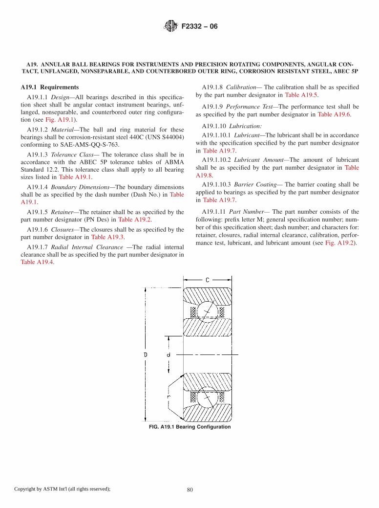
A19. ANNULAR BALL BEARINGS FOR INSTRUMENTS AND PRECISION ROTATING COMPONENTS, ANGULAR CON-TACT, UNFLANGED, NONSEPARABLE, AND COUNTERBORED OUTER RING, CORROSION RESISTANT STEEL, ABEC 5P
A19.1 Requirements
A19.1.1 Design—All bearings described in this specifica-tion sheet shall be angular contact instrument bearings, unf-langed, nonseparable, and counterbored outer ring configura-tion (see Fig. A19.1).
A19.1.2 Material—The ball and ring material for thesebearings shall be corrosion-resistant steel 440C (UNS S44004)conforming to SAE-AMS-QQ-S-763.
A19.1.3 Tolerance Class— The tolerance class shall be inaccordance with the ABEC 5P tolerance tables of ABMAStandard 12.2. This tolerance class shall apply to all bearingsizes listed in Table A19.1.
A19.1.4 Boundary Dimensions—The boundary dimensionsshall be as specified by the dash number (Dash No.) in TableA19.1.
A19.1.5 Retainer—The retainer shall be as specified by thepart number designator (PN Des) in Table A19.2.
A19.1.6 Closures—The closures shall be as specified by thepart number designator in Table A19.3.
A19.1.7 Radial Internal Clearance —The radial internalclearance shall be as specified by the part number designator inTable A19.4.
A19.1.8 Calibration— The calibration shall be as specifiedby the part number designator in Table A19.5.
A19.1.9 Performance Test—The performance test shall beas specified by the part number designator in Table A19.6.
A19.1.10 Lubrication:
A19.1.10.1 Lubricant—The lubricant shall be in accordancewith the specification specified by the part number designatorin Table A19.7.
A19.1.10.2 Lubricant Amount—The amount of lubricantshall be as specified by the part number designator in TableA19.8.
A19.1.10.3 Barrier Coating— The barrier coating shall beapplied to bearings as specified by the part number designatorin Table A19.7.
A19.1.11 Part Number— The part number consists of thefollowing: prefix letter M; general specification number; num-ber of this specification sheet; dash number; and characters for:retainer, closures, radial internal clearance, calibration, perfor-mance test, lubricant, and lubricant amount (see Fig. A19.2).
FIG. A19.1 Bearing Configuration
F2332 − 06
80Copyright by ASTM Int'l (all rights reserved);

TABLE A19.1 Boundary Dimensions, inches
DashNo.
Bored
ODD
WidthC
RadiusrA,B
-AA 0.0400 0.1250 0.0469 0.003-BA 0.0469 0.1562 0.0625 0.003-BC 0.0469 0.1562 0.0937 0.003-CA 0.0550 0.1875 0.0781 0.003-CB 0.0550 0.1875 0.1094 0.003-DA 0.0781 0.2500 0.0937 0.003-DB 0.0781 0.2500 0.1406 0.003-DC 0.0781 0.2500 0.1094 0.003-EA 0.0937 0.1875 0.0625 0.003-EB 0.0937 0.1875 0.0937 0.003-EC 0.0937 0.2500 0.0625 0.003-ED 0.0937 0.2500 0.0937 0.003-EE 0.0937 0.2500 0.1094 0.003-EF 0.0937 0.2883 0.0625 0.003-KG 0.0937 0.3125 0.0625 0.003-EH 0.0937 0.3125 0.1094 0.003-EJ 0.0937 0.3125 0.1406 0.003-EK 0.0937 0.4100 0.1094 0.003-FA 0.1250 0.2500 0.0937 0.003-FB 0.1250 0.2500 0.1094 0.003-FC 0.1250 0.3125 0.1094 0.003-FD 0.1250 0.3125 0.1406 0.003-FE 0.1250 0.3750 0.1094 0.005-FF 0.1250 0.3750 0.1406 0.005-FG 0.1250 0.3750 0.1562 0.012-FH 0.1250 0.4100 0.0937 0.003-FJ 0.1250 0.4100 0.1094 0.003-FK 0.1250 0.4250 0.0937 0.003-FL 0.1250 0.4250 0.1094 0.003-FM 0.1250 0.4375 0.1094 0.003-FN 0.1250 0.4375 0.1406 0.003-FP 0.1250 0.5000 0.1094 0.003-FR 0.1250 0.5000 0.1719 0.012-FT 0.1250 0.7500 0.1250 0.010-FV 0.1250 0.3750 0.0937 0.003-GA 0.1562 0.3125 0.1094 0.003-GB 0.1562 0.3125 0.1250 0.003-HA 0.1875 0.3125 0.1094 0.003-HB 0.1875 0.3125 0.1250 0.003-HC 0.1875 0.3750 0.1094 0.003-HD 0.1875 0.3750 0.1250 0.003-HE 0.1875 0.4100 0.1094 0.003-HF 0.1875 0.4250 0.1094 0.003-HG 0.1875 0.4375 0.1094 0.003-HH 0.1875 0.5000 0.1094 0.003-HJ 0.1875 0.5000 0.1562 0.012-HK 0.1875 0.5000 0.1960 0.012-HL 0.1875 0.7435 0.1960 0.012-HM 0.1875 0.7500 0.1960 0.012-HN 0.1875 0.8750 0.1960 0.012-JA 0.2500 0.3750 0.1250 0.003-JB 0.2500 0.5000 0.1094 0.003-JC 0.2500 0.5000 0.1250 0.005-JD 0.2500 0.5000 0.1875 0.005-JE 0.2500 0.6250 0.1960 0.012-JF 0.2500 0.7500 0.1960 0.012-JG 0.2500 0.7500 0.2188 0.016-JH 0.2500 0.7500 0.2812 0.016-JJ 0.2500 0.8750 0.1960 0.012-JK 0.2500 1.0000 0.1960 0.012-JL 0.2500 1.0480 0.1960 0.012-KA 0.3125 0.5000 0.1562 0.005-KB 0.3125 0.6250 0.1562 0.010-LA 0.3750 0.8750 0.2188 0.016-LB 0.3750 0.8750 0.2812 0.016-MA 0.5000 0.8750 0.2188 0.016-MB 0.5000 0.8750 0.2812 0.016-MC 0.5000 1.1250 0.2500 0.016-MD 0.5000 1.1250 0.3125 0.016-NA 0.6250 1.3750 0.2812 0.031-NB 0.6250 1.3750 0.3438 0.031
A Maximum shaft or housing fillet radius that bearing corners will clear.B Narrow face of rings shall have a maximum r value of one half the value listedprovided this quantity does not fall below 0.003 inches.
TABLE A19.2 Retainer
PN Des Type
0 no retainer, full complement6 PTFE toroidsA
7 phenolic laminateB ,C
8 vacuum-impregnated phenolicC ,D
9 nonporous, nonmetallicC
A PTFE (polytetrafluoroethylene).B Phenolic or other porous non-metallic material.C Used for high-speed applications.D Phenolic or other porous nonmetallic material saturated with lubricant. Selectionof this choice dictates choosing manufacturer’s standard amount of lubricant.
TABLE A19.3 Closures
PN Des Number Type
N none none
TABLE A19.4 Radial Internal Clearance or Contact Angle
PN Des Range
1 0.0001 to 0.0003 in.2 0.0003 to 0.0005 in.3 14° or lessA
4 greater than 14° but less than 20°A
5 0.0005 to 0.0008 in.6 greater than 20°A
8 0.0008 to 0.0011 in.9 As specified in contract
A Angular contact bearing designations only.
TABLE A19.5 Calibration of Bore and Outside Diameter (OD)
PN Des Bore Increments OD Increments
N no calibration no calibrationA no calibration 0.00010B no calibration 0.00005C 0.00010 no calibrationD 0.00010 0.00010E 0.00010 0.00005F 0.00005 no calibrationG 0.00005 0.00010H 0.00005 0.00005
F2332 − 06
81Copyright by ASTM Int'l (all rights reserved);

TABLE A19.6 Performance Test
PN Des Type
1 manufacturer’s standard2 starting torqueA
A Starting torque limits from Table 2 of base document.
TABLE A19.7 Lubricant
PN Des Specification
P preservativeA
A MIL-PRF-6085B MIL-PRF-6085B
C DOD-L-81846D DOD-L-81846B
E MIL-PRF-23827F MIL-PRF-81322G MIL-G-81937H MIL-PRF-83261J MIL-S-81087C
K MIL-S-81087C
L MIL-DTL-53131, Grade 4M MIL-DTL-53131, Grade 6N MIL-DTL-53131, Grade 9Q MIL-DTL-53131, Grade 14R MIL-DTL-53131, Grade 40S As specified in contract
A PN Des “P” shall be used only with PN Des “P” in Table A19.8.B With barrier coat.C Canceled – lube no longer manufactured.
TABLE A19.8 Lubricant Amount
PN Des Quantity
P preservative amount as required byMIL-DTL-197
1 manufacturer’s standardA
2 oil per Table 5 of base document3 15 % grease4 25 % grease5 35 % grease6 45 % grease7 As specified in contract
A Grease: fill to minimum 25 %, maximum 40 % of bearing void. Oil: immerse andthen allow excess to drip off. The standard quantity of oil varies with each bearingsize.
F2332 − 06
82Copyright by ASTM Int'l (all rights reserved);

FIG. A19.2 Part Number
F2332 − 06
83Copyright by ASTM Int'l (all rights reserved);

A20. ANNULAR BALL BEARINGS FOR INSTRUMENTS AND PRECISION ROTATING COMPONENTS, ANGULAR CON-TACT, UNFLANGED, NONSEPARABLE, AND COUNTERBORED OUTER RING, CORROSION RESISTANT STEEL, ABEC 7P
A20.1 Requirements
A20.1.1 Design—All bearings described in this specifica-tion sheet shall be angular contact instrument bearings, unf-langed, nonseparable, and counterbored outer ring configura-tion (see Fig. A20.1).
A20.1.2 Material—The ball and ring material for thesebearings shall be corrosion-resistant steel 440C (UNS S44004)conforming to SAE-AMS-QQ-S-763.
A20.1.3 Tolerance Class— The tolerance class shall be inaccordance with the ABEC 7P tolerance tables of ABMAStandard 12.2. This tolerance class shall apply to all bearingsizes listed in Table A20.1.
A20.1.4 Boundary Dimensions—The boundary dimensionsshall be as specified by the dash number (Dash No.) in TableA20.1.
A20.1.5 Retainer—The retainer shall be as specified by thepart number designator (PN Des) in Table A20.2.
A20.1.6 Closures—The closures shall be as specified by thepart number designator in Table A20.3.
A20.1.7 Radial Internal Clearance —The radial internalclearance shall be as specified by the part number designator inTable A20.4.
A20.1.8 Calibration— The calibration shall be as specifiedby the part number designator in Table A20.5.
A20.1.9 Performance Test—The performance test shall beas specified by the part number designator in Table A20.6.
A20.1.10 Lubrication:
A20.1.10.1 Lubricant—The lubricant shall be in accordancewith the specification specified by the part number designatorin Table A20.7.
A20.1.10.2 Lubricant Amount—The amount of lubricantshall be as specified by the part number designator in TableA20.8.
A20.1.10.3 Barrier Coating— The barrier coating shall beapplied to bearings as specified by the part number designatorin Table A20.7.
A20.1.11 Part Number— The part number consists of thefollowing: prefix letter M; general specification number; num-ber of this specification sheet; dash number; and characters for:retainer, closures, radial internal clearance, calibration, perfor-mance test, lubricant, and lubricant amount (see Fig. A20.2).
FIG. A20.1 Bearing Configuration
F2332 − 06
84Copyright by ASTM Int'l (all rights reserved);

TABLE A20.1 Boundary Dimensions, inches
DashNo.
Bored
ODD
WidthC
RadiusrA,B
-AA 0.0400 0.1250 0.0469 0.003-BA 0.0469 0.1562 0.0625 0.003-BC 0.0469 0.1562 0.0937 0.003-CA 0.0550 0.1875 0.0781 0.003-CB 0.0550 0.1875 0.1094 0.003-DA 0.0781 0.2500 0.0937 0.003-DB 0.0781 0.2500 0.1406 0.003-DC 0.0781 0.2500 0.1094 0.003-EA 0.0937 0.1875 0.0625 0.003-EB 0.0937 0.1875 0.0937 0.003-EC 0.0937 0.2500 0.0625 0.003-ED 0.0937 0.2500 0.0937 0.003-EE 0.0937 0.2500 0.1094 0.003-EF 0.0937 0.2883 0.0625 0.003-KG 0.0937 0.3125 0.0625 0.003-EH 0.0937 0.3125 0.1094 0.003-EJ 0.0937 0.3125 0.1406 0.003-EK 0.0937 0.4100 0.1094 0.003-FA 0.1250 0.2500 0.0937 0.003-FB 0.1250 0.2500 0.1094 0.003-FC 0.1250 0.3125 0.1094 0.003-FD 0.1250 0.3125 0.1406 0.003-FE 0.1250 0.3750 0.1094 0.005-FF 0.1250 0.3750 0.1406 0.005-FG 0.1250 0.3750 0.1562 0.012-FH 0.1250 0.4100 0.0937 0.003-FJ 0.1250 0.4100 0.1094 0.003-FK 0.1250 0.4250 0.0937 0.003-FL 0.1250 0.4250 0.1094 0.003-FM 0.1250 0.4375 0.1094 0.003-FN 0.1250 0.4375 0.1406 0.003-FP 0.1250 0.5000 0.1094 0.003-FR 0.1250 0.5000 0.1719 0.012-FT 0.1250 0.7500 0.1250 0.010-FV 0.1250 0.3750 0.0937 0.003-GA 0.1562 0.3125 0.1094 0.003-GB 0.1562 0.3125 0.1250 0.003-HA 0.1875 0.3125 0.1094 0.003-HB 0.1875 0.3125 0.1250 0.003-HC 0.1875 0.3750 0.1094 0.003-HD 0.1875 0.3750 0.1250 0.003-HE 0.1875 0.4100 0.1094 0.003-HF 0.1875 0.4250 0.1094 0.003-HG 0.1875 0.4375 0.1094 0.003-HH 0.1875 0.5000 0.1094 0.003-HJ 0.1875 0.5000 0.1562 0.012-HK 0.1875 0.5000 0.1960 0.012-HL 0.1875 0.7435 0.1960 0.012-HM 0.1875 0.7500 0.1960 0.012-HN 0.1875 0.8750 0.1960 0.012-JA 0.2500 0.3750 0.1250 0.003-JB 0.2500 0.5000 0.1094 0.003-JC 0.2500 0.5000 0.1250 0.005-JD 0.2500 0.5000 0.1875 0.005-JE 0.2500 0.6250 0.1960 0.012-JF 0.2500 0.7500 0.1960 0.012-JG 0.2500 0.7500 0.2188 0.016-JH 0.2500 0.7500 0.2812 0.016-JJ 0.2500 0.8750 0.1960 0.012-JK 0.2500 1.0000 0.1960 0.012-JL 0.2500 1.0480 0.1960 0.012-KA 0.3125 0.5000 0.1562 0.005-KB 0.3125 0.6250 0.1562 0.010-LA 0.3750 0.8750 0.2188 0.016-LB 0.3750 0.8750 0.2812 0.016-MA 0.5000 0.8750 0.2188 0.016-MB 0.5000 0.8750 0.2812 0.016-MC 0.5000 1.1250 0.2500 0.016-MD 0.5000 1.1250 0.3125 0.016-NA 0.6250 1.3750 0.2812 0.031-NB 0.6250 1.3750 0.3438 0.031
A Maximum shaft or housing fillet radius that bearing corners will clear.B Narrow face of rings shall have a maximum r value of one half the value listedprovided this quantity does not fall below 0.003 inches.
TABLE A20.2 Retainer
PN Des Type
0 no retainer, full complement6 PTFE toroidsA
7 phenolic laminateB ,C
8 vacuum-impregnated phenolicC ,D
9 nonporous, nonmetallicC
A PTFE (polytetrafluoroethylene).B Phenolic or other porous non-metallic material.C Used for high-speed applications.D Phenolic or other porous nonmetallic material saturated with lubricant. Selectionof this choice dictates choosing manufacturer’s standard amount of lubricant.
TABLE A20.3 Closures
PN Des Number Type
N none none
TABLE A20.4 Radial Internal Clearance or Contact Angle
PN Des Range
1 0.0001 to 0.0003 in.2 0.0003 to 0.0005 in.3 14° or lessA
4 greater than 14° but less than 20°A
5 0.0005 to 0.0008 in.6 greater than 20°A
8 0.0008 to 0.0011 in.9 As specified in contract
A Angular contact bearing designations only.
TABLE A20.5 Calibration of Bore and Outside Diameter (OD)
PN Des Bore Increments OD Increments
N no calibration no calibrationA no calibration 0.00010B no calibration 0.00005C 0.00010 no calibrationD 0.00010 0.00010E 0.00010 0.00005F 0.00005 no calibrationG 0.00005 0.00010H 0.00005 0.00005
F2332 − 06
85Copyright by ASTM Int'l (all rights reserved);

TABLE A20.6 Performance Test
PN Des Type
1 manufacturer’s standard2 starting torqueA
A Starting torque limits from Table 2 of base document.
TABLE A20.7 Lubricant
PN Des Specification
P preservativeA
A MIL-PRF-6085B MIL-PRF-6085B
C DOD-L-81846D DOD-L-81846B
E MIL-PRF-23827F MIL-PRF-81322G MIL-G-81937H MIL-PRF-83261J MIL-S-81087C
K MIL-S-81087C
L MIL-DTL-53131, Grade 4M MIL-DTL-53131, Grade 6N MIL-DTL-53131, Grade 9Q MIL-DTL-53131, Grade 14R MIL-DTL-53131, Grade 40S As specified in contract
A PN Des “P” shall be used only with PN Des “P” in Table A20.8.B With barrier coat.C Canceled – lube no longer manufactured.
TABLE A20.8 Lubricant Amount
PN Des Quantity
P preservative amount as required byMIL-DTL-197
1 manufacturer’s standardA
2 oil per Table 5 of base document3 15 % grease4 25 % grease5 35 % grease6 45 % grease7 As specified in contract
A Grease: fill to minimum 25 %, maximum 40 % of bearing void. Oil: immerse andthen allow excess to drip off. The standard quantity of oil varies with each bearingsize.
F2332 − 06
86Copyright by ASTM Int'l (all rights reserved);

FIG. A20.2 Part Number
F2332 − 06
87Copyright by ASTM Int'l (all rights reserved);

A21. ANNULAR BALL BEARINGS FOR INSTRUMENTS AND PRECISION ROTATING COMPONENTS, ANGULAR CON-TACT, FLANGED, NONSEPARABLE, AND COUNTERBORED OUTER RING ON FLANGE SIDE, CHROMIUM ALLOY
STEEL, ABEC 5P
A21.1 Requirements
A21.1.1 Design—All bearings described in this specifica-tion sheet shall be angular contact instrument bearings with aflanged, nonseparable, and counterbored outer ring on theflange side (see Fig. A21.1).
A21.1.2 Material—The ball and ring material for thesebearings shall be chromium-alloy steel 52100 (UNS G52986)conforming to SAE-AMS 6444.
A21.1.3 Tolerance Class— The tolerance class shall be inaccordance with the ABEC 5P tolerance tables of ABMAStandard 12.2. This tolerance class shall apply to all bearingsizes listed in Table A21.1.
A21.1.4 Boundary Dimensions—The boundary dimensionsshall be as specified by the dash number (Dash No.) in TableA21.1.
A21.1.5 Retainer—The retainer shall be as specified by thepart number designator (PN Des) in Table A21.2.
A21.1.6 Closures—Closures are not available for this typeof bearing. Part number designator N shall be used as shown inTable A21.3.
A21.1.7 Radial Internal Clearance or Contact Angle—Theradial internal clearance or contact angle shall be as specifiedby the part number designator in Table A21.4.
A21.1.8 Calibration— The calibration shall be as specifiedby the part number designator in Table A21.5.
A21.1.9 Performance Test—The performance test shall beas specified by the part number designator in Table A21.6.
A21.1.10 Lubrication:
A21.1.10.1 Lubricant—The lubricant shall be in accordancewith the specification specified by the part number designatorin Table A21.7.
A21.1.10.2 Lubricant Amount—The amount of lubricantshall be as specified by the part number designator in TableA21.8.
A21.1.10.3 Barrier Coating— The barrier coating shall beapplied to bearings as specified by the part number designatorin Table A21.7.
A21.1.11 Part Number— The part number consists of thefollowing: prefix letter M; general specification number; num-ber of this specification sheet; dash number; and characters for:retainer, closures, radial internal clearance or contact angle,calibration, performance test, lubricant, and lubricant amount(see Fig. A21.2).
FIG. A21.1 Bearing Configuration
F2332 − 06
88Copyright by ASTM Int'l (all rights reserved);

TABLE A21.1 Boundary Dimensions, inches
DashNo.
Bored
ODD
WidthC
FlangeODD1
FlangeWidth
C1
RadiusrA,B
-AA 0.0400 0.1250 0.0469 0.171 0.013 0.003-BA 0.0469 0.1562 0.0625 0.203 0.013 0.003-BB 0.0469 0.1562 0.0937 0.203 0.031 0.003-CA 0.0550 0.1875 0.0781 0.234 0.031 0.003-CB 0.0550 0.1875 0.1094 0.234 0.031 0.003-DA 0.0781 0.2500 0.0937 0.296 0.023 0.003-DB 0.0781 0.2500 0.1406 0.296 0.031 0.003-EA 0.0937 0.1875 0.0625 0.234 0.018 0.003-EB 0.0937 0.1875 0.0937 0.234 0.031 0.003-EC 0.0937 0.3125 0.1094 0.359 0.023 0.003-ED 0.0937 0.3125 0.1406 0.359 0.031 0.003-FA 0.1250 0.2500 0.0937 0.296 0.023 0.003-FB 0.1250 0.2500 0.1094 0.296 0.031 0.003-FC 0.1250 0.3125 0.1094 0.359 0.023 0.003-FD 0.1250 0.3125 0.1406 0.359 0.031 0.003-FE 0.1250 0.3750 0.1094 0.422 0.023 0.005-FF 0.1250 0.3750 0.1406 0.422 0.031 0.005-FG 0.1250 0.3750 0.1562 0.440 0.030 0.012-GA 0.1562 0.3125 0.1094 0.359 0.023 0.003-GB 0.1562 0.3125 0.1250 0.359 0.036 0.003-HA 0.1875 0.3750 0.1250 0.422 0.023 0.003-HB 0.1875 0.3750 0.1250 0.422 0.031 0.003-HC 0.1875 0.5000 0.1562 0.565 0.042 0.012-HD 0.1875 0.5000 0.1960 0.565 0.042 0.012-HE 0.1875 0.3125 0.1094 0.359 0.023 0.003-HF 0.1875 0.3125 0.1250 0.359 0.036 0.003-JA 0.2500 0.3750 0.1250 0.422 0.023 0.003-JB 0.2500 0.3750 0.1250 0.422 0.036 0.003-JC 0.2500 0.5000 0.1250 0.547 0.023 0.005-JD 0.2500 0.5000 0.1875 0.547 0.045 0.005-JE 0.2500 0.6250 0.1960 0.690 0.042 0.012-KA 0.3125 0.5000 0.1562 0.547 0.031 0.005-LA 0.3750 0.8750 0.2188 0.969 0.062 0.016-LB 0.3750 0.8750 0.2812 0.969 0.062 0.016-MA 0.5000 1.1250 0.2500 1.225 0.062 0.016-MB 0.5000 1.1250 0.3125 1.225 0.062 0.016
A Maximum shaft or housing fillet radius that bearing corners will clear.B Narrow face of rings shall have a maximum r value of one half the value listedprovided this quantity does not fall below 0.003 inches.
TABLE A21.2 Retainer
PN Des Type
0 no retainer, full complement6 PTFE toroidsA
7 phenolic-type laminateB ,C
8 vacuum-impregnated phenolicC ,D
9 nonporous, nonmetallicC
A PTFE (polytetrafluoroethylene).B Phenolic or other porous non-metallic material.C Used for high-speed applications.D Phenolic or other porous nonmetallic material saturated with lubricant. Selectionof this choice dictates choosing manufacturer’s standard amount of lubricant.
TABLE A21.3 Closures
PN Des Number Type
N none none
TABLE A21.4 Radial Internal Clearance or Contact Angle
PN Des Range
1 0.0001 to 0.0003 in.2 0.0003 to 0.0005 in.3 14° or lessA
4 greater than 14° but less than 20°A
5 0.0005 to 0.0008 in.6 greater than 20°A
8 0.0008 to 0.0011 in.9 As specified in contract
A Angular contact bearing designations only.
TABLE A21.5 Calibration of Bore and Outside Diameter (OD)
PN Des Bore Increments OD Increments
N no calibration no calibrationA no calibration 0.00010B no calibration 0.00005C 0.00010 no calibrationD 0.00010 0.00010E 0.00010 0.00005F 0.00005 no calibrationG 0.00005 0.00010H 0.00005 0.00005
TABLE A21.6 Performance Test
PN Des Type
1 manufacturer’s standard2 starting torqueA
A Starting torque limits from Table 2 of base document.
TABLE A21.7 Lubricant
PN Des Specification
P preservativeA
A MIL-PRF-6085B MIL-PRF-6085B
C DOD-L-81846D DOD-L-81846B
E MIL-PRF-23827F MIL-PRF-81322G MIL-G-81937H MIL-PRF-83261J MIL-S-81087C
K MIL-S-81087C
L MIL-DTL-53131, Grade 4M MIL-DTL-53131, Grade 6N MIL-DTL-53131, Grade 9Q MIL-DTL-53131, Grade 14R MIL-DTL-53131, Grade 40S As specified in contract
A PN Des “P” shall be used only with PN Des “P” in Table A21.8.B With barrier coat.C Canceled – lube no longer manufactured.
F2332 − 06
89Copyright by ASTM Int'l (all rights reserved);

TABLE A21.8 Lubricant Amount
PN Des Quantity
P preservative amount as required byMIL-DTL-197
1 manufacturer’s standardA
2 oil per Table 5 of base document3 15 % grease4 25 % grease5 35 % grease6 45 % grease7 As specified in contract
A Grease: fill to minimum 25 %, maximum 40 % of bearing void. Oil: immerse andthen allow excess to drip off. The standard quantity of oil varies with each bearingsize.
FIG. A21.2 Part Number
F2332 − 06
90Copyright by ASTM Int'l (all rights reserved);

A22. ANNULAR BALL BEARINGS FOR INSTRUMENTS AND PRECISION ROTATING COMPONENTS, ANGULAR CON-TACT, FLANGED, NONSEPARABLE, AND COUNTERBORED OUTER RING ON FLANGE SIDE, CHROMIUM ALLOY
STEEL, ABEC 7P
A22.1 Requirements
A22.1.1 Design—All bearings described in this specifica-tion sheet shall be angular contact instrument bearings with aflanged, nonseparable, and counterbored outer ring on theflange side (see Fig. A22.1).
A22.1.2 Material—The ball and ring material for thesebearings shall be chromium-alloy steel 52100 (UNS G52986)conforming to SAE-AMS 6444.
A22.1.3 Tolerance Class— The tolerance class shall be inaccordance with the ABEC 7P tolerance tables of ABMAStandard 12.2. This tolerance class shall apply to all bearingsizes listed in Table A22.1.
A22.1.4 Boundary Dimensions—The boundary dimensionsshall be as specified by the dash number (Dash No.) in TableA22.1.
A22.1.5 Retainer—The retainer shall be as specified by thepart number designator (PN Des) in Table A22.2.
A22.1.6 Closures—Closures are not available for this typeof bearing. Part number designator N shall be used as shown inTable A22.3.
A22.1.7 Radial Internal Clearance or Contact Angle—Theradial internal clearance or contact angle shall be as specifiedby the part number designator in Table A22.4.
A22.1.8 Calibration— The calibration shall be as specifiedby the part number designator in Table A22.5.
A22.1.9 Performance Test—The performance test shall beas specified by the part number designator in Table A22.6.
A22.1.10 Lubrication:
A22.1.10.1 Lubricant—The lubricant shall be in accordancewith the specification specified by the part number designatorin Table A22.7.
A22.1.10.2 Lubricant Amount—The amount of lubricantshall be as specified by the part number designator in TableA22.8.
A22.1.10.3 Barrier Coating— The barrier coating shall beapplied to bearings as specified by the part number designatorin Table A22.7.
A22.1.11 Part Number— The part number consists of thefollowing: prefix letter M; general specification number; num-ber of this specification sheet; dash number; and characters for:retainer, closures, radial internal clearance, calibration, perfor-mance test, lubricant, and lubricant amount (see Fig. A22.2).
FIG. A22.1 Bearing Configuration
F2332 − 06
91Copyright by ASTM Int'l (all rights reserved);

TABLE A22.1 Boundary Dimensions, inches
DashNo.
Bored
ODD
WidthC
FlangeODD1
FlangeWidth
C1
RadiusrA,B
-AA 0.0400 0.1250 0.0469 0.171 0.013 0.003-BA 0.0469 0.1562 0.0625 0.203 0.013 0.003-BB 0.0469 0.1562 0.0937 0.203 0.031 0.003-CA 0.0550 0.1875 0.0781 0.234 0.031 0.003-CB 0.0550 0.1875 0.1094 0.234 0.031 0.003-DA 0.0781 0.2500 0.0937 0.296 0.023 0.003-DB 0.0781 0.2500 0.1406 0.296 0.031 0.003-EA 0.0937 0.1875 0.0625 0.234 0.018 0.003-EB 0.0937 0.1875 0.0937 0.234 0.031 0.003-EC 0.0937 0.3125 0.1094 0.359 0.023 0.003-ED 0.0937 0.3125 0.1406 0.359 0.031 0.003-FA 0.1250 0.2500 0.0937 0.296 0.023 0.003-FB 0.1250 0.2500 0.1094 0.296 0.031 0.003-FC 0.1250 0.3125 0.1094 0.359 0.023 0.003-FD 0.1250 0.3125 0.1406 0.359 0.031 0.003-FE 0.1250 0.3750 0.1094 0.422 0.023 0.005-FF 0.1250 0.3750 0.1406 0.422 0.031 0.005-FG 0.1250 0.3750 0.1562 0.440 0.030 0.012-GA 0.1562 0.3125 0.1094 0.359 0.023 0.003-GB 0.1562 0.3125 0.1250 0.359 0.036 0.003-HA 0.1875 0.3750 0.1250 0.422 0.023 0.003-HB 0.1875 0.3750 0.1250 0.422 0.031 0.003-HC 0.1875 0.5000 0.1562 0.565 0.042 0.012-HD 0.1875 0.5000 0.1960 0.565 0.042 0.012-HE 0.1875 0.3125 0.1094 0.359 0.023 0.003-HF 0.1875 0.3125 0.1250 0.359 0.036 0.003-JA 0.2500 0.3750 0.1250 0.422 0.023 0.003-JB 0.2500 0.3750 0.1250 0.422 0.036 0.003-JC 0.2500 0.5000 0.1250 0.547 0.023 0.005-JD 0.2500 0.5000 0.1875 0.547 0.045 0.005-JE 0.2500 0.6250 0.1960 0.690 0.042 0.012-KA 0.3125 0.5000 0.1562 0.547 0.031 0.005-LA 0.3750 0.8750 0.2188 0.969 0.062 0.016-LB 0.3750 0.8750 0.2812 0.969 0.062 0.016-MA 0.5000 1.1250 0.2500 1.225 0.062 0.016-MB 0.5000 1.1250 0.3125 1.225 0.062 0.016
A Maximum shaft or housing fillet radius that bearing corners will clear.B Narrow face of rings shall have a maximum r value of one half the value listedprovided this quantity does not fall below 0.003 inches.
TABLE A22.2 Retainer
PN Des Type
0 no retainer, full complement6 PTFE toroidsA
7 phenolic-type laminateB ,C
8 vacuum-impregnated phenolicC ,D
9 nonporous, nonmetallicC
A PTFE (polytetrafluoroethylene).B Phenolic or other porous non-metallic material.C Used for high-speed applications.D Phenolic or other porous nonmetallic material saturated with lubricant. Selectionof this choice dictates choosing manufacturer’s standard amount of lubricant.
TABLE A22.3 Closures
PN Des Number Type
N none none
TABLE A22.4 Radial Internal Clearance or Contact Angle
PN Des Range
1 0.0001 to 0.0003 in.2 0.0003 to 0.0005 in.3 14° or lessA
4 greater than 14° but less than 20°A
5 0.0005 to 0.0008 in.6 greater than 20°A
8 0.0008 to 0.0011 in.9 As specified in contract
A Angular contact bearing designations only.
TABLE A22.5 Calibration of Bore and Outside Diameter (OD)
PN Des Bore Increments OD Increments
N no calibration no calibrationA no calibration 0.00010B no calibration 0.00005C 0.00010 no calibrationD 0.00010 0.00010E 0.00010 0.00005F 0.00005 no calibrationG 0.00005 0.00010H 0.00005 0.00005
TABLE A22.6 Performance Test
PN Des Type
1 manufacturer’s standard2 starting torqueA
A Starting torque limits from Table 2 of base document.
TABLE A22.7 Lubricant
PN Des Specification
P preservativeA
A MIL-PRF-6085B MIL-PRF-6085B
C DOD-L-81846D DOD-L-81846B
E MIL-PRF-23827F MIL-PRF-81322G MIL-G-81937H MIL-PRF-83261J MIL-S-81087C
K MIL-S-81087C
L MIL-DTL-53131, Grade 4M MIL-DTL-53131, Grade 6N MIL-DTL-53131, Grade 9Q MIL-DTL-53131, Grade 14R MIL-DTL-53131, Grade 40S As specified in contract
A PN Des “P” shall be used only with PN Des “P” in Table A22.8.B With barrier coat.C Canceled – lube no longer manufactured.
F2332 − 06
92Copyright by ASTM Int'l (all rights reserved);

TABLE A22.8 Lubricant Amount
PN Des Quantity
P preservative amount as required byMIL-DTL-197
1 manufacturer’s standardA
2 oil per Table 5 of base document3 15 % grease4 25 % grease5 35 % grease6 45 % grease7 As specified in contract
A Grease: fill to minimum 25 %, maximum 40 % of bearing void. Oil: immerse andthen allow excess to drip off. The standard quantity of oil varies with each bearingsize.
FIG. A22.2 Part Number
F2332 − 06
93Copyright by ASTM Int'l (all rights reserved);

A23. ANNULAR BALL BEARINGS FOR INSTRUMENTS AND PRECISION ROTATING COMPONENTS, ANGULAR CON-TACT, FLANGED, NONSEPARABLE, AND COUNTERBORED OUTER RING ON FLANGE SIDE, CORROSION-RESISTANT
STEEL, ABEC 5P
A23.1 Requirements
A23.1.1 Design—All bearings described in this specifica-tion sheet shall be angular contact instrument bearings with aflanged, nonseparable, and counterbored outer ring on theflange side (see Fig. A23.1).
A23.1.2 Material—The ball and ring material for thesebearings shall be corrosion-resistant steel 440C (UNS S44004)conforming to SAE-AMS-QQ-S-763.
A23.1.3 Tolerance Class— The tolerance class shall be inaccordance with the ABEC 5P tolerance tables of ABMAStandard 12.2. This tolerance class shall apply to all bearingsizes listed in Table A23.1.
A23.1.4 Boundary Dimensions—The boundary dimensionsshall be as specified by the dash number (Dash No.) in TableA23.1.
A23.1.5 Retainer—The retainer shall be as specified by thepart number designator (PN Des) in Table A23.2.
A23.1.6 Closures—Closures are not available for this typeof bearing. Part number designator N shall be as shown inTable A23.3.
A23.1.7 Radial Internal Clearance or Contact Angle—Theradial internal clearance or contact angle shall be as specifiedby the part number designator in Table A23.4.
A23.1.8 Calibration— The calibration shall be as specifiedby the part number designator in Table A23.5.
A23.1.9 Performance Test—The performance test shall beas specified by the part number designator in Table A23.6.
A23.1.10 Lubrication:
A23.1.10.1 Lubricant—The lubricant shall be in accordancewith the specification specified by the part number designatorin Table A23.7.
A23.1.10.2 Lubricant Amount—The amount of lubricantshall be as specified by the part number designator in TableA23.8.
A23.1.10.3 Barrier Coating— The barrier coating shall beapplied to bearings as specified by the part number designatorin Table A23.7.
A23.1.11 Part Number— The part number consists of thefollowing: prefix letter M; general specification number; num-ber of this specification sheet; dash number; and characters for:retainer, closures, radial internal clearance or contact angle,calibration, performance test, lubricant, and lubricant amount(see Fig. A23.2).
FIG. A23.1 Bearing Configuration
F2332 − 06
94Copyright by ASTM Int'l (all rights reserved);

TABLE A23.1 Boundary Dimensions, inches
DashNo.
Bored
ODD
WidthC
FlangeODD1
FlangeWidth
C1
RadiusrA,B
-AA 0.0400 0.1250 0.0469 0.171 0.013 0.003-BA 0.0469 0.1562 0.0625 0.203 0.013 0.003-BB 0.0469 0.1562 0.0937 0.203 0.031 0.003-CA 0.0550 0.1875 0.0781 0.234 0.031 0.003-CB 0.0550 0.1875 0.1094 0.234 0.031 0.003-DA 0.0781 0.2500 0.0937 0.296 0.023 0.003-DB 0.0781 0.2500 0.1406 0.296 0.031 0.003-EA 0.0937 0.1875 0.0625 0.234 0.018 0.003-EB 0.0937 0.1875 0.0937 0.234 0.031 0.003-EC 0.0937 0.3125 0.1094 0.359 0.023 0.003-ED 0.0937 0.3125 0.1406 0.359 0.031 0.003-FA 0.1250 0.2500 0.0937 0.296 0.023 0.003-FB 0.1250 0.2500 0.1094 0.296 0.031 0.003-FC 0.1250 0.3125 0.1094 0.359 0.023 0.003-FD 0.1250 0.3125 0.1406 0.359 0.031 0.003-FE 0.1250 0.3750 0.1094 0.422 0.023 0.005-FF 0.1250 0.3750 0.1406 0.422 0.031 0.005-FG 0.1250 0.3750 0.1562 0.440 0.030 0.012-GA 0.1562 0.3125 0.1094 0.359 0.023 0.003-GB 0.1562 0.3125 0.1250 0.359 0.036 0.003-HA 0.1875 0.3750 0.1250 0.422 0.023 0.003-HB 0.1875 0.3750 0.1250 0.422 0.031 0.003-HC 0.1875 0.5000 0.1562 0.565 0.042 0.012-HD 0.1875 0.5000 0.1960 0.565 0.042 0.012-HE 0.1875 0.3125 0.1094 0.359 0.023 0.003-HF 0.1875 0.3125 0.1250 0.359 0.036 0.003-JA 0.2500 0.3750 0.1250 0.422 0.023 0.003-JB 0.2500 0.3750 0.1250 0.422 0.036 0.003-JC 0.2500 0.5000 0.1250 0.547 0.023 0.005-JD 0.2500 0.5000 0.1875 0.547 0.045 0.005-JE 0.2500 0.6250 0.1960 0.690 0.042 0.012-KA 0.3125 0.5000 0.1562 0.547 0.031 0.005-LA 0.3750 0.8750 0.2188 0.969 0.062 0.016-LB 0.3750 0.8750 0.2812 0.969 0.062 0.016-MA 0.5000 1.1250 0.2500 1.225 0.062 0.016-MB 0.5000 1.1250 0.3125 1.225 0.062 0.016
A Maximum shaft or housing fillet radius that bearing corners will clear.B Narrow face of rings shall have a maximum r value of one half the value listedprovided this quantity does not fall below 0.003 inches.
TABLE A23.2 Retainer
PN Des Type
0 no retainer, full complement6 PTFE toroidsA
7 phenolic-type laminateB ,C
8 vacuum-impregnated phenolicC ,D
9 nonporous, nonmetallicC
A PTFE (polytetrafluoroethylene).B Phenolic or other porous nonmetallic material.C Used for high-speed applications.D Phenolic or other porous nonmetallic material saturated with lubricant. Selectionof this choice dictates choosing manufacturer’s standard amount of lubricant.
TABLE A23.3 Closures
PN Des Number Type
N none none
TABLE A23.4 Radial Internal Clearance or Contact Angle
PN Des Range
1 0.0001 to 0.0003 in.2 0.0003 to 0.0005 in.3 14° or lessA
4 greater than 14° but less than 20°A
5 0.0005 to 0.0008 in.6 greater than 20°A
8 0.0008 to 0.0011 in.9 As specified in contract
A Angular contact bearing designations only.
TABLE A23.5 Calibration of Bore and Outside Diameter (OD)
PN Des Bore Increments OD Increments
N no calibration no calibrationA no calibration 0.00010B no calibration 0.00005C 0.00010 no calibrationD 0.00010 0.00010E 0.00010 0.00005F 0.00005 no calibrationG 0.00005 0.00010H 0.000 05 0.00005
TABLE A23.6 Performance Test
PN Des Type
1 manufacturer’s standard2 starting torqueA
A Starting torque limits from Table 2 of base document.
TABLE A23.7 Lubricant
PN Des Specification
P preservativeA
A MIL-PRF-6085B MIL-PRF-6085B
C DOD-L-81846D DOD-L-81846B
E MIL-PRF-23827F MIL-PRF-81322G MIL-G-81937H MIL-PRF-83261J MIL-S-81087C
K MIL-S-81087C
L MIL-DTL-53131, Grade 4M MIL-DTL-53131, Grade 6N MIL-DTL-53131, Grade 9Q MIL-DTL-53131, Grade 14R MIL-DTL-53131, Grade 40S As specified in contract
A PN Des “P” shall be used only with PN Des “P” in Table A23.8.B With barrier coat.C Canceled – lube no longer manufactured.
F2332 − 06
95Copyright by ASTM Int'l (all rights reserved);
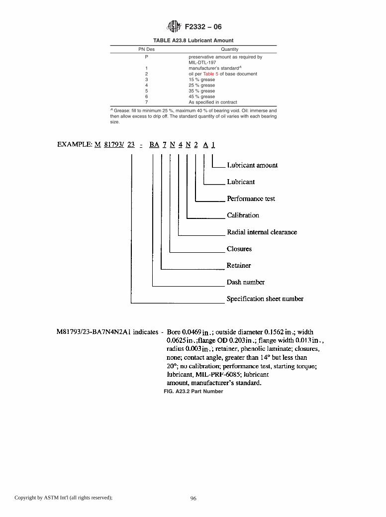
TABLE A23.8 Lubricant Amount
PN Des Quantity
P preservative amount as required byMIL-DTL-197
1 manufacturer’s standardA
2 oil per Table 5 of base document3 15 % grease4 25 % grease5 35 % grease6 45 % grease7 As specified in contract
A Grease: fill to minimum 25 %, maximum 40 % of bearing void. Oil: immerse andthen allow excess to drip off. The standard quantity of oil varies with each bearingsize.
FIG. A23.2 Part Number
F2332 − 06
96Copyright by ASTM Int'l (all rights reserved);

A24. ANNULAR BALL BEARINGS FOR INSTRUMENTS AND PRECISION ROTATING COMPONENTS, ANGULAR CON-TACT, FLANGED, NONSEPARABLE, AND COUNTERBORED OUTER RING ON FLANGE SIDE, CORROSION-RESISTANT
STEEL, ABEC 7P
A24.1 Requirements
A24.1.1 Design—All bearings described in this specifica-tion sheet shall be angular contact instrument bearings with aflanged, nonseparable, and counterbored outer ring on theflange side (see Fig. A24.1).
A24.1.2 Material—The ball and ring material for thesebearings shall be corrosion-resistant steel 440C (UNS S44004)conforming to SAE-AMS-QQ-S-763.
A24.1.3 Tolerance Class— The tolerance class shall be inaccordance with the ABEC 7P tolerance tables of ABMAStandard 12.2. This tolerance class shall apply to all bearingsizes listed in Table A24.1.
A24.1.4 Boundary Dimensions—The boundary dimensionsshall be as specified by the dash number (Dash No.) in TableA24.1.
A24.1.5 Retainer—The retainer shall be as specified by thepart number designator (PN Des) in Table A24.2.
A24.1.6 Closures—Closures are not available for this typeof bearing. Part number designator N shall be used as shown inTable A24.3.
A24.1.7 Radial Internal Clearance or Contact Angle—Theradial internal clearance or contact angle shall be as specifiedby the part number designator in Table A24.4.
A24.1.8 Calibration— The calibration shall be as specifiedby the part number designator in Table A24.5.
A24.1.9 Performance Test—The performance test shall beas specified by the part number designator in Table A24.6.
A24.1.10 Lubrication:
A24.1.10.1 Lubricant—The lubricant shall be in accordancewith the specification specified by the part number designatorin Table A24.7.
A24.1.10.2 Lubricant Amount—The amount of lubricantshall be as specified by the part number designator in TableA24.8.
A24.1.10.3 Barrier Coating— The barrier coating shall beapplied to bearings as specified by the part number designatorin Table A24.7.
A24.1.11 Part Number— The part number consists of thefollowing: prefix letter M; general specification number; num-ber of this specification sheet; dash number; and characters for:retainer, closures, radial internal clearance, calibration, perfor-mance test, lubricant, and lubricant amount (see Fig. A24.2).
FIG. A24.1 Bearing Configuration
F2332 − 06
97Copyright by ASTM Int'l (all rights reserved);

TABLE A24.1 Boundary Dimensions, inches
DashNo.
Bored
ODD
WidthC
FlangeODD1
FlangeWidth
C1
RadiusrA,B
-AA 0.0400 0.1250 0.0469 0.171 0.013 0.003-BA 0.0469 0.1562 0.0625 0.203 0.013 0.003-BB 0.0469 0.1562 0.0937 0.203 0.031 0.003-CA 0.0550 0.1875 0.0781 0.234 0.031 0.003-CB 0.0550 0.1875 0.1094 0.234 0.031 0.003-DA 0.0781 0.2500 0.0937 0.296 0.023 0.003-DB 0.0781 0.2500 0.1406 0.296 0.031 0.003-EA 0.0937 0.1875 0.0625 0.234 0.018 0.003-EB 0.0937 0.1875 0.0937 0.234 0.031 0.003-EC 0.0937 0.3125 0.1094 0.359 0.023 0.003-ED 0.0937 0.3125 0.1406 0.359 0.031 0.003-FA 0.1250 0.2500 0.0937 0.296 0.023 0.003-FB 0.1250 0.2500 0.1094 0.296 0.031 0.003-FC 0.1250 0.3125 0.1094 0.359 0.023 0.003-FD 0.1250 0.3125 0.1406 0.359 0.031 0.003-FE 0.1250 0.3750 0.1094 0.422 0.023 0.005-FF 0.1250 0.3750 0.1406 0.422 0.031 0.005-FG 0.1250 0.3750 0.1562 0.440 0.030 0.012-GA 0.1562 0.3125 0.1094 0.359 0.023 0.003-GB 0.1562 0.3125 0.1250 0.359 0.036 0.003-HA 0.1875 0.3750 0.1250 0.422 0.023 0.003-HB 0.1875 0.3750 0.1250 0.422 0.031 0.003-HC 0.1875 0.5000 0.1562 0.565 0.042 0.012-HD 0.1875 0.5000 0.1960 0.565 0.042 0.012-HE 0.1875 0.3125 0.1094 0.359 0.023 0.003-HF 0.1875 0.3125 0.1250 0.359 0.036 0.003-JA 0.2500 0.3750 0.1250 0.422 0.023 0.003-JB 0.2500 0.3750 0.1250 0.422 0.036 0.003-JC 0.2500 0.5000 0.1250 0.547 0.023 0.005-JD 0.2500 0.5000 0.1875 0.547 0.045 0.005-JE 0.2500 0.6250 0.1960 0.690 0.042 0.012-KA 0.3125 0.5000 0.1562 0.547 0.031 0.005-LA 0.3750 0.8750 0.2188 0.969 0.062 0.016-LB 0.3750 0.8750 0.2812 0.969 0.062 0.016-MA 0.5000 1.1250 0.2500 1.225 0.062 0.016-MB 0.5000 1.1250 0.3125 1.225 0.062 0.016
A Maximum shaft or housing fillet radius that bearing corners will clear.B Narrow face of rings shall have a maximum r value of one half the value listedprovided this quantity does not fall below 0.003 inches.
TABLE A24.2 Retainer
PN Des Type
0 no retainer, full complement6 PTFE toroidsA
7 Pphenolic-type laminateB ,C
8 vacuum-impregnated phenolicC ,D
9 nonporous, nonmetallicC
A PTFE (polytetrafluoroethylene).B Phenolic or other porous nonmetallic material.C Used for high-speed applications.D Phenolic or other porous nonmetallic material saturated with lubricant. Selectionof this choice dictates choosing manufacturer’s standard amount of lubricant.
TABLE A24.3 Closures
PN Des Number Type
N none none
TABLE A24.4 Radial Internal Clearance or Contact Angle
PN Des Range
1 0.0001 to 0.0003 in.2 0.0003 to 0.0005 in.3 14° or lessA
4 greater than 14° but less than 20°A
5 0.0005 to 0.0008 in.6 greater than 20°A
8 0.0008 to 0.0011 in.9 As specified in contract
A Angular contact bearing designations only.
TABLE A24.5 Calibration of Bore and Outside Diameter (OD)
PN Des Bore Increments OD Increments
N no calibration no calibrationA no calibration 0.00010B no calibration 0.00005C 0.00010 no calibrationD 0.00010 0.00010E 0.00010 0.00005F 0.00005 no calibrationG 0.00005 0.00010H 0.00005 0.00005
TABLE A24.6 Performance Test
PN Des Type
1 manufacturer’s standard2 starting torqueA
A Starting torque limits from Table 2 of base document.
TABLE A24.7 Lubricant
PN Des Specification
P preservativeA
A MIL-PRF-6085B MIL-PRF-6085B
C DOD-L-81846D DOD-L-81846B
E MIL-PRF-23827F MIL-PRF-81322G MIL-G-81937H MIL-PRF-83261J MIL-S-81087C
K MIL-S-81087C
L MIL-DTL-53131, Grade 4M MIL-DTL-53131, Grade 6N MIL-DTL-53131, Grade 9Q MIL-DTL-53131, Grade 14R MIL-DTL-53131, Grade 40S As specified in contract
A PN Des “P” shall be used only with PN Des “P” in Table A24.8.B With barrier coat.C Canceled – lube no longer manufactured.
F2332 − 06
98Copyright by ASTM Int'l (all rights reserved);

TABLE A24.8 Lubricant Amount
PN Des Quantity
P preservative amount as required byMIL-DTL-197
1 manufacturer’s standardA
2 oil per Table 5 of base document3 15 % grease4 25 % grease5 35 % grease6 45 % grease7 As specified in contract
A Grease: fill to minimum 25 %, maximum 40 % of bearing void. Oil: immerse andthen allow excess to drip off. The standard quantity of oil varies with each bearingsize.
FIG. A24.2 Part Number
F2332 − 06
99Copyright by ASTM Int'l (all rights reserved);

A25. ANNULAR BALL BEARING FOR INSTRUMENTS AND PRECISION ROTATING COMPONENTS, ANGULAR CON-TACT, UNFLANGED, SEPARABLE AND STEPPED INNER RING, CHROMIUM ALLOY STEEL, ABEC 5P
A25.1 Requirements
A25.1.1 Design—All bearings described in this annex shallbe angular contact instrument bearings with an unflanged,separable, and stepped inner ring configuration (see Fig.A25.1).
A25.1.2 Material—The ball and ring material for thesebearings shall be chromium-alloy steel 52100 (UNS G52986)conforming to SAE-AMS 6444.
A25.1.3 Tolerance Class— The tolerance class shall be inaccordance with the ABEC 5P tolerance tables of ABMAStandard 12.2. This tolerance class shall apply to all bearingsizes listed in Table A25.1.
A25.1.4 Boundary Dimensions—The boundary dimensionsshall be as specified by the dash number (Dash No.) in TableA25.1.
A25.1.5 Retainer—The retainer shall be as specified by thepart number designator (PN Des) in Table A25.2.
A25.1.6 Closures—Closures are not available for this typeof bearing. Part number designator N shall be used as shown inTable A25.3.
A25.1.7 Radial Internal Clearance or Contact Angle—Theradial internal clearance or contact angle shall be as specifiedby the part number designator in Table A25.4.
A25.1.8 Calibration— The calibration shall be as specifiedby the part number designator in Table A25.5.
A25.1.9 Performance Test—The performance test shall beas specified by the part number designator in Table A25.6.
A25.1.10 Lubrication:
A25.1.10.1 Lubricant—The lubricant shall be in accordancewith the specification indicated by the part number designatorin Table A25.7.
A25.1.10.2 Lubricant Amount—The amount of lubricantshall be as specified by the part number designator in TableA25.8.
A25.1.10.3 Barrier Coating— The barrier coating shall beapplied to bearings as specified by the part number designatorin Table A25.7.
A25.1.11 Part Number— The part number consists of thefollowing: prefix letter M; general specification number; num-ber of this specification sheet; dash number; and characters for:retainer, closures, radial internal clearance or contact angle,calibration, performance test, lubricant, and lubricant amount(see Fig. A25.2).
FIG. A25.1 Bearing Configuration
F2332 − 06
100Copyright by ASTM Int'l (all rights reserved);

TABLE A25.1 Boundary Dimensions, inches
DashNo.
Bored
ODD
WidthC
RadiusrA,B
-AA 0.0400 0.1250 0.0469 0.003-BA 0.0469 0.1562 0.0625 0.003-BB 0.0469 0.1562 0.0937 0.003-CA 0.0550 0.1875 0.0781 0.003-CB 0.0550 0.1875 0.1094 0.003-DA 0.0781 0.2500 0.0937 0.003-DB 0.0781 0.2500 0.1406 0.003-DC 0.0781 0.2500 0.1094 0.003-EA 0.0937 0.1875 0.0625 0.003-EB 0.0937 0.1875 0.0937 0.003-EC 0.0937 0.3125 0.1094 0.003-ED 0.0937 0.3125 0.1406 0.003-EE 0.0937 0.2500 0.1094 0.003-EF 0.0937 0.2883 0.0625 0.003-KG 0.0937 0.3125 0.0625 0.003-EH 0.0937 0.3125 0.1094 0.003-EJ 0.0937 0.3125 0.1406 0.003-EK 0.0937 0.4100 0.1094 0.003-FA 0.1250 0.2500 0.0937 0.003-FB 0.1250 0.2500 0.1094 0.003-FC 0.1250 0.3125 0.1094 0.003-FD 0.1250 0.3125 0.1406 0.003-FE 0.1250 0.3750 0.1094 0.005-FF 0.1250 0.3750 0.1406 0.005-FG 0.1250 0.3750 0.1562 0.012-FH 0.1250 0.4100 0.0937 0.003-FJ 0.1250 0.4100 0.1094 0.003-FK 0.1250 0.4250 0.0937 0.003-FL 0.1250 0.4250 0.1094 0.003-FM 0.1250 0.4375 0.1094 0.003-FN 0.1250 0.4375 0.1406 0.003-FP 0.1250 0.5000 0.1094 0.003-FR 0.1250 0.5000 0.1719 0.012-FT 0.1250 0.7500 0.1250 0.010-FV 0.1250 0.3750 0.0937 0.003-GA 0.1562 0.3125 0.1094 0.003-GB 0.1562 0.3125 0.1250 0.003-HA 0.1875 0.3125 0.1094 0.003-HB 0.1875 0.3125 0.1250 0.003-HC 0.1875 0.3750 0.1094 0.003-HD 0.1875 0.3750 0.1250 0.003-HE 0.1875 0.4100 0.1094 0.003-HF 0.1875 0.4250 0.1094 0.003-HG 0.1875 0.4375 0.1094 0.003-HH 0.1875 0.5000 0.1094 0.003-HJ 0.1875 0.5000 0.1562 0.012-HK 0.1875 0.5000 0.1960 0.012-HL 0.1875 0.7435 0.1960 0.012-HM 0.1875 0.7500 0.1960 0.012-HN 0.1875 0.8750 0.1960 0.012-JA 0.2500 0.3750 0.1250 0.003-JB 0.2500 0.5000 0.1094 0.003-JC 0.2500 0.5000 0.1250 0.005-JD 0.2500 0.5000 0.1875 0.005-JE 0.2500 0.6250 0.1960 0.012-JF 0.2500 0.7500 0.1960 0.012-JG 0.2500 0.7500 0.2188 0.016-JH 0.2500 0.7500 0.2812 0.016-JJ 0.2500 0.8750 0.1960 0.012-JK 0.2500 1.0000 0.1960 0.012-JL 0.2500 1.0480 0.1960 0.012-KA 0.3125 0.5000 0.1562 0.005-KB 0.3125 0.6250 0.1562 0.010-LA 0.3750 0.8750 0.2188 0.016-LB 0.3750 0.8750 0.2812 0.016-MA 0.5000 0.8750 0.2188 0.016-MG 0.5000 0.8750 0.2812 0.016-MC 0.5000 1.1250 0.2500 0.016-MD 0.5000 1.1250 0.3125 0.016-NA 0.6250 1.3750 0.2812 0.031-NB 0.6250 1.3750 0.3438 0.031
A Maximum shaft or housing fillet radius that bearing corners will clear.B Narrow face of rings shall have a maximum r value of one half the value listedprovided this quantity does not fall below 0.003 inches.
TABLE A25.2 Retainer
PN Des Type
7 phenolic-type laminateA ,B
8 vacuum-impregnated phenolicB ,C
9 nonporous, nonmetallicB
A Phenolic or other porous nonmetallic material.B Used for high-speed applications.C Phenolic or other porous nonmetallic material saturated with lubricant. Selectionof this choice dictates choosing manufacturer’s standard amount of lubricant.
TABLE A25.3 Closures
PN Des Number Type
N none none
TABLE A25.4 Radial Internal Clearance or Contact Angle
PN Des Range
1 0.0001 to 0.0003 in.2 0.0003 to 0.0005 in.3 14° or lessA
4 greater than 14° but less than 20°A
5 0.0005 to 0.0008 in.6 greater than 20°A
8 0.0008 to 0.0011 in.9 As specified in contract
A Angular contact bearing designations only.
TABLE A25.5 Calibration of Bore and Outside Diameter (OD)
PN Des Bore Increments OD Increments
N no calibration no calibrationA no calibration 0.00010B no calibration 0.00005C 0.00010 no calibrationD 0.00010 0.00010E 0.00010 0.00005F 0.00005 no calibrationG 0.00005 0.00010H 0.00005 0.00005
F2332 − 06
101Copyright by ASTM Int'l (all rights reserved);

TABLE A25.6 Performance Test
PN Des Type
1 manufacturer’s standard2 starting torqueA
A Starting torque limits from Table 2 of base document.
TABLE A25.7 Lubricant
PN Des Specification
P preservativeA
A MIL-PRF-6085B MIL-PRF-6085B
C DOD-L-81846D DOD-L-81846B
E MIL-PRF-23827F MIL-PRF-81322G MIL-G-81937H MIL-PRF-83261J MIL-S-81087C
K MIL-S-81087C
L MIL-DTL-53131, Grade 4M MIL-DTL-53131, Grade 6N MIL-DTL-53131, Grade 9Q MIL-DTL-53131, Grade 14R MIL-DTL-53131, Grade 40S As specified in contract
A PN Des “P” shall be used only with PN Des “P” in Table A25.8.B With barrier coat.C Canceled – lube no longer manufactured.
TABLE A25.8 Lubricant Amount
PN Des Quantity
P preservative amount as required byMIL-DTL-197
1 manufacturer’s standardA
2 oil per Table 5 of base document3 15 % grease4 25 % grease5 35 % grease6 45 % grease7 As specified in contract
A Grease: fill to minimum 25 %, maximum 40 % of bearing void. Oil: immerse andthen allow excess to drip off. The standard quantity of oil varies with each bearingsize.
F2332 − 06
102Copyright by ASTM Int'l (all rights reserved);

FIG. A25.2 Part Number
F2332 − 06
103Copyright by ASTM Int'l (all rights reserved);
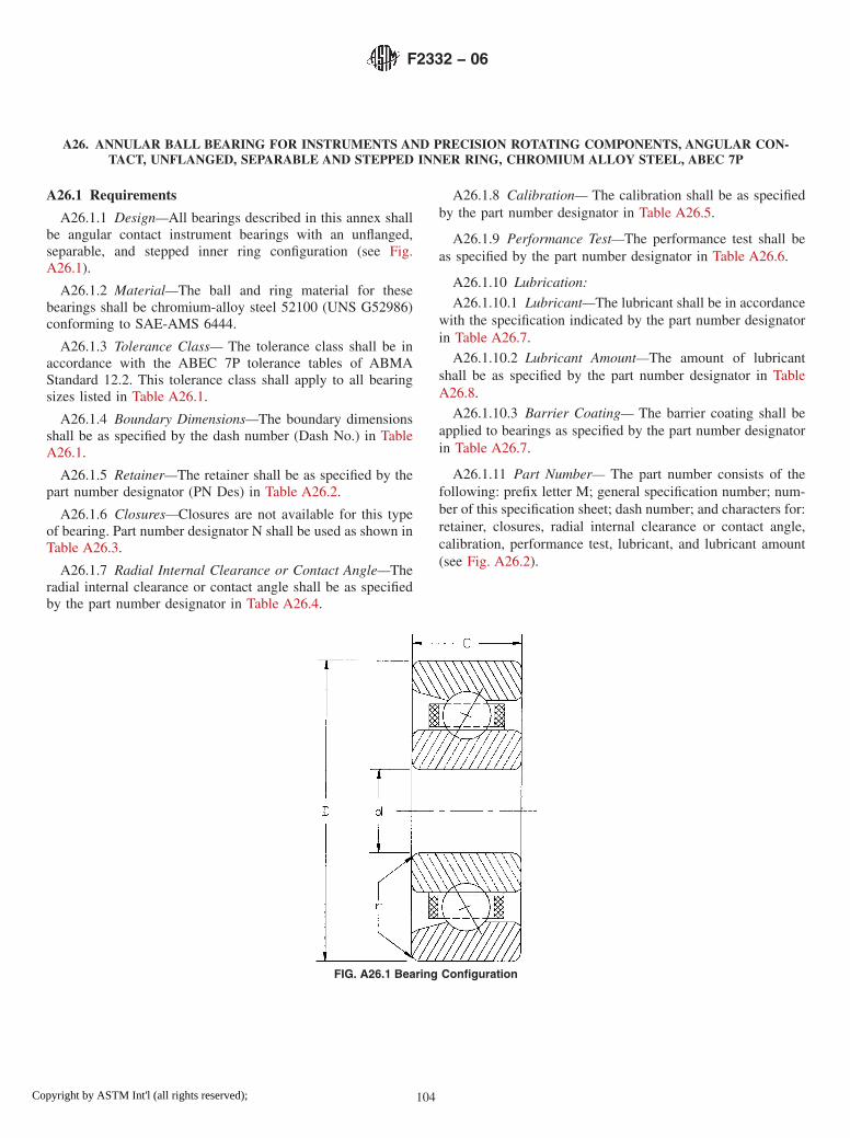
A26. ANNULAR BALL BEARING FOR INSTRUMENTS AND PRECISION ROTATING COMPONENTS, ANGULAR CON-TACT, UNFLANGED, SEPARABLE AND STEPPED INNER RING, CHROMIUM ALLOY STEEL, ABEC 7P
A26.1 Requirements
A26.1.1 Design—All bearings described in this annex shallbe angular contact instrument bearings with an unflanged,separable, and stepped inner ring configuration (see Fig.A26.1).
A26.1.2 Material—The ball and ring material for thesebearings shall be chromium-alloy steel 52100 (UNS G52986)conforming to SAE-AMS 6444.
A26.1.3 Tolerance Class— The tolerance class shall be inaccordance with the ABEC 7P tolerance tables of ABMAStandard 12.2. This tolerance class shall apply to all bearingsizes listed in Table A26.1.
A26.1.4 Boundary Dimensions—The boundary dimensionsshall be as specified by the dash number (Dash No.) in TableA26.1.
A26.1.5 Retainer—The retainer shall be as specified by thepart number designator (PN Des) in Table A26.2.
A26.1.6 Closures—Closures are not available for this typeof bearing. Part number designator N shall be used as shown inTable A26.3.
A26.1.7 Radial Internal Clearance or Contact Angle—Theradial internal clearance or contact angle shall be as specifiedby the part number designator in Table A26.4.
A26.1.8 Calibration— The calibration shall be as specifiedby the part number designator in Table A26.5.
A26.1.9 Performance Test—The performance test shall beas specified by the part number designator in Table A26.6.
A26.1.10 Lubrication:
A26.1.10.1 Lubricant—The lubricant shall be in accordancewith the specification indicated by the part number designatorin Table A26.7.
A26.1.10.2 Lubricant Amount—The amount of lubricantshall be as specified by the part number designator in TableA26.8.
A26.1.10.3 Barrier Coating— The barrier coating shall beapplied to bearings as specified by the part number designatorin Table A26.7.
A26.1.11 Part Number— The part number consists of thefollowing: prefix letter M; general specification number; num-ber of this specification sheet; dash number; and characters for:retainer, closures, radial internal clearance or contact angle,calibration, performance test, lubricant, and lubricant amount(see Fig. A26.2).
FIG. A26.1 Bearing Configuration
F2332 − 06
104Copyright by ASTM Int'l (all rights reserved);

TABLE A26.1 Boundary Dimensions, inches
DashNo.
Bored
ODD
WidthC
RadiusrA,B
-AA 0.0400 0.1250 0.0469 0.003-BA 0.0469 0.1562 0.0625 0.003-BB 0.0469 0.1562 0.0937 0.003-CA 0.0550 0.1875 0.0781 0.003-CB 0.0550 0.1875 0.1094 0.003-DA 0.0781 0.2500 0.0937 0.003-DB 0.0781 0.2500 0.1406 0.003-DC 0.0781 0.2500 0.1094 0.003-EA 0.0937 0.1875 0.0625 0.003-EB 0.0937 0.1875 0.0937 0.003-EC 0.0937 0.3125 0.1094 0.003-ED 0.0937 0.3125 0.1406 0.003-EE 0.0937 0.2500 0.1094 0.003-EF 0.0937 0.2883 0.0625 0.003-KG 0.0937 0.3125 0.0625 0.003-EH 0.0937 0.3125 0.1094 0.003-EJ 0.0937 0.3125 0.1406 0.003-EK 0.0937 0.4100 0.1094 0.003-FA 0.1250 0.2500 0.0937 0.003-FB 0.1250 0.2500 0.1094 0.003-FC 0.1250 0.3125 0.1094 0.003-FD 0.1250 0.3125 0.1406 0.003-FE 0.1250 0.3750 0.1094 0.005-FF 0.1250 0.3750 0.1406 0.005-FG 0.1250 0.3750 0.1562 0.012-FH 0.1250 0.4100 0.0937 0.003-FJ 0.1250 0.4100 0.1094 0.003-FK 0.1250 0.4250 0.0937 0.003-FL 0.1250 0.4250 0.1094 0.003-FM 0.1250 0.4375 0.1094 0.003-FN 0.1250 0.4375 0.1406 0.003-FP 0.1250 0.5000 0.1094 0.003-FR 0.1250 0.5000 0.1719 0.012-FT 0.1250 0.7500 0.1250 0.010-FV 0.1250 0.3750 0.0937 0.003-GA 0.1562 0.3125 0.1094 0.003-GB 0.1562 0.3125 0.1250 0.003-HA 0.1875 0.3125 0.1094 0.003-HB 0.1875 0.3125 0.1250 0.003-HC 0.1875 0.3750 0.1094 0.003-HD 0.1875 0.3750 0.1250 0.003-HE 0.1875 0.4100 0.1094 0.003-HF 0.1875 0.4250 0.1094 0.003-HG 0.1875 0.4375 0.1094 0.003-HH 0.1875 0.5000 0.1094 0.003-HJ 0.1875 0.5000 0.1562 0.012-HK 0.1875 0.5000 0.1960 0.012-HL 0.1875 0.7435 0.1960 0.012-HM 0.1875 0.7500 0.1960 0.012-HN 0.1875 0.8750 0.1960 0.012-JA 0.2500 0.3750 0.1250 0.003-JB 0.2500 0.5000 0.1094 0.003-JC 0.2500 0.5000 0.1250 0.005-JD 0.2500 0.5000 0.1875 0.005-JE 0.2500 0.6250 0.1960 0.012-JF 0.2500 0.7500 0.1960 0.012-JG 0.2500 0.7500 0.2188 0.016-JH 0.2500 0.7500 0.2812 0.016-JJ 0.2500 0.8750 0.1960 0.012-JK 0.2500 1.0000 0.1960 0.012-JL 0.2500 1.0480 0.1960 0.012-KA 0.3125 0.5000 0.1562 0.005-KB 0.3125 0.6250 0.1562 0.010-LA 0.3750 0.8750 0.2188 0.016-LB 0.3750 0.8750 0.2812 0.016-MA 0.5000 0.8750 0.2188 0.016-MG 0.5000 0.8750 0.2812 0.016-MC 0.5000 1.1250 0.2500 0.016-MD 0.5000 1.1250 0.3125 0.016-NA 0.6250 1.3750 0.2812 0.031-NB 0.6250 1.3750 0.3438 0.031
A Maximum shaft or housing fillet radius that bearing corners will clear.B Narrow face of rings shall have a maximum r value of one half the value listedprovided this quantity does not fall below 0.003 inches.
TABLE A26.2 Retainer
PN Des Type
7 phenolic-type laminateA ,B
8 vacuum-impregnated phenolicB ,C
9 nonporous, nonmetallicB
A Phenolic or other porous nonmetallic material.B Used for high-speed applications.C Phenolic or other porous nonmetallic material saturated with lubricant. Selectionof this choice dictates choosing manufacturer’s standard amount of lubricant.
TABLE A26.3 Closures
PN Des Number Type
N none none
TABLE A26.4 Radial Internal Clearance or Contact Angle
PN Des Range
1 0.0001 to 0.0003 in.2 0.0003 to 0.0005 in.3 14° or lessA
4 greater than 14° but less than 20°A
5 0.0005 to 0.0008 in.6 greater than 20°A
8 0.0008 to 0.0011 in.9 As specified in contract
A Angular contact bearing designations only.
TABLE A26.5 Calibration of Bore and Outside Diameter (OD)
PN Des Bore Increments OD Increments
N no calibration no calibrationA no calibration 0.00010B no calibration 0.00005C 0.00010 no calibrationD 0.00010 0.00010E 0.00010 0.00005F 0.00005 no calibrationG 0.00005 0.00010H 0.00005 0.00005
F2332 − 06
105Copyright by ASTM Int'l (all rights reserved);

TABLE A26.6 Performance Test
PN Des Type
1 manufacturer’s standard2 starting torqueA
A Starting torque limits from Table 2 of base document.
TABLE A26.7 Lubricant
PN Des Specification
P preservativeA
A MIL-PRF-6085B MIL-PRF-6085B
C DOD-L-81846D DOD-L-81846B
E MIL-PRF-23827F MIL-PRF-81322G MIL-G-81937H MIL-PRF-83261J MIL-S-81087C
K MIL-S-81087C
L MIL-DTL-53131, Grade 4M MIL-DTL-53131, Grade 6N MIL-DTL-53131, Grade 9Q MIL-DTL-53131, Grade 14R MIL-DTL-53131, Grade 40S As specified in contract
A PN Des “P” shall be used only with PN Des “P” in Table A26.8.B With barrier coat.C Canceled – lube no longer manufactured.
TABLE A26.8 Lubricant Amount
PN Des Quantity
P preservative amount as required byMIL-DTL-197
1 manufacturer’s standardA
2 oil per Table 5 of base document3 15 % grease4 25 % grease5 35 % grease6 45 % grease7 As specified in contract
A Grease: fill to minimum 25 %, maximum 40 % of bearing void. Oil: immerse andthen allow excess to drip off. The standard quantity of oil varies with each bearingsize.
F2332 − 06
106Copyright by ASTM Int'l (all rights reserved);

FIG. A26.2 Part Number
F2332 − 06
107Copyright by ASTM Int'l (all rights reserved);

A27. ANNULAR BALL BEARING FOR INSTRUMENTS AND PRECISION ROTATING COMPONENTS, ANGULAR CON-TACT, UNFLANGED, SEPARABLE AND STEPPED INNER RING, CORROSION-RESISTANT STEEL, ABEC 5P
A27.1 Requirements
A27.1.1 Design—All bearings described in this annex shallbe angular contact instrument bearings with an unflanged,separable, and stepped inner ring configuration (see Fig.A27.1).
A27.1.2 Material—The ball and ring material for thesebearings shall be corrosion-resistant steel 440C (UNS S44004)conforming to SAE-AMS-QQ-S-763.
A27.1.3 Tolerance Class— The tolerance class shall be inaccordance with the ABEC 5P tolerance tables of ABMAStandard 12.2. This tolerance class shall apply to all bearingsizes listed in Table A27.1.
A27.1.4 Boundary Dimensions—The boundary dimensionsshall be as specified by the dash number (Dash No.) in TableA27.1.
A27.1.5 Retainer—The retainer shall be as specified by thepart number designator (PN Des) in Table A27.2.
A27.1.6 Closures—Closures are not available for this typeof bearing. Part number designator N shall not be used asshown in Table A27.3.
A27.1.7 Radial Internal Clearance or Contact Angle—Theradial internal clearance or contact angle shall be as specifiedby the part number designator in Table A27.4.
A27.1.8 Calibration— The calibration shall be as specifiedby the part number designator in Table A27.5.
A27.1.9 Performance Test—The performance test shall beas specified by the part number designator in Table A27.6.
A27.1.10 Lubrication:
A27.1.10.1 Lubricant—The lubricant shall be in accordancewith the specification indicated by the part number designatorin Table A27.7.
A27.1.10.2 Lubricant Amount—The amount of lubricantshall be as specified by the part number designator in TableA27.8.
A27.1.10.3 Barrier Coating— The barrier coating shall beapplied to bearings as specified by the part number designatorin Table A27.7.
A27.1.11 Part Number— The part number consists of thefollowing: prefix letter M; general specification number; num-ber of this specification sheet; dash number; and characters for:retainer, closures, radial internal clearance or contact angle,calibration, performance test, lubricant, and lubricant amount(see Fig. A27.2).
FIG. A27.1 Bearing Configuration
F2332 − 06
108Copyright by ASTM Int'l (all rights reserved);
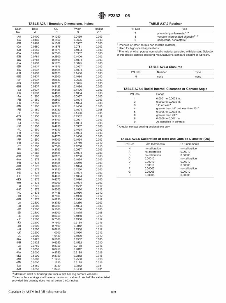
TABLE A27.1 Boundary Dimensions, inches
DashNo.
Bored
ODD
WidthC
RadiusrA,B
-AA 0.0400 0.1250 0.0469 0.003-BA 0.0469 0.1562 0.0625 0.003-BB 0.0469 0.1562 0.0937 0.003-CA 0.0550 0.1875 0.0781 0.003-CB 0.0550 0.1875 0.1094 0.003-DA 0.0781 0.2500 0.0937 0.003-DB 0.0781 0.2500 0.1406 0.003-DC 0.0781 0.2500 0.1094 0.003-EA 0.0937 0.1875 0.0625 0.003-EB 0.0937 0.1875 0.0937 0.003-EC 0.0937 0.3125 0.1094 0.003-ED 0.0937 0.3125 0.1406 0.003-EE 0.0937 0.2500 0.1094 0.003-EF 0.0937 0.2883 0.0625 0.003-KG 0.0937 0.3125 0.0625 0.003-EH 0.0937 0.3125 0.1094 0.003-EJ 0.0937 0.3125 0.1406 0.003-EK 0.0937 0.4100 0.1094 0.003-FA 0.1250 0.2500 0.0937 0.003-FB 0.1250 0.2500 0.1094 0.003-FC 0.1250 0.3125 0.1094 0.003-FD 0.1250 0.3125 0.1406 0.003-FE 0.1250 0.3750 0.1094 0.005-FF 0.1250 0.3750 0.1406 0.005-FG 0.1250 0.3750 0.1562 0.012-FH 0.1250 0.4100 0.0937 0.003-FJ 0.1250 0.4100 0.1094 0.003-FK 0.1250 0.4250 0.0937 0.003-FL 0.1250 0.4250 0.1094 0.003-FM 0.1250 0.4375 0.1094 0.003-FN 0.1250 0.4375 0.1406 0.003-FP 0.1250 0.5000 0.1094 0.003-FR 0.1250 0.5000 0.1719 0.012-FT 0.1250 0.7500 0.1250 0.010-FV 0.1250 0.3750 0.0937 0.003-GA 0.1562 0.3125 0.1094 0.003-GB 0.1562 0.3125 0.1250 0.003-HA 0.1875 0.3125 0.1094 0.003-HB 0.1875 0.3125 0.1250 0.003-HC 0.1875 0.3750 0.1094 0.003-HD 0.1875 0.3750 0.1250 0.003-HE 0.1875 0.4100 0.1094 0.003-HF 0.1875 0.4250 0.1094 0.003-HG 0.1875 0.4375 0.1094 0.003-HH 0.1875 0.5000 0.1094 0.003-HJ 0.1875 0.5000 0.1562 0.012-HK 0.1875 0.5000 0.1960 0.012-HL 0.1875 0.7435 0.1960 0.012-HM 0.1875 0.7500 0.1960 0.012-HN 0.1875 0.8750 0.1960 0.012-JA 0.2500 0.3750 0.1250 0.003-JB 0.2500 0.5000 0.1094 0.003-JC 0.2500 0.5000 0.1250 0.005-JD 0.2500 0.5000 0.1875 0.005-JE 0.2500 0.6250 0.1960 0.012-JF 0.2500 0.7500 0.1960 0.012-JG 0.2500 0.7500 0.2188 0.016-JH 0.2500 0.7500 0.2812 0.016-JJ 0.2500 0.8750 0.1960 0.012-JK 0.2500 1.0000 0.1960 0.012-JL 0.2500 1.0480 0.1960 0.012-KA 0.3125 0.5000 0.1562 0.005-KB 0.3125 0.6250 0.1562 0.010-LA 0.3750 0.8750 0.2188 0.016-LB 0.3750 0.8750 0.2812 0.016-MA 0.5000 0.8750 0.2188 0.016-MG 0.5000 0.8750 0.2812 0.016-MC 0.5000 1.1250 0.2500 0.016-MD 0.5000 1.1250 0.3125 0.016-NA 0.6250 1.3750 0.2812 0.031-NB 0.6250 1.3750 0.3438 0.031
A Maximum shaft or housing fillet radius that bearing corners will clear.B Narrow face of rings shall have a maximum r value of one half the value listedprovided this quantity does not fall below 0.003 inches.
TABLE A27.2 Retainer
PN Des Type
7 phenolic-type laminateA ,B
8 vacuum-impregnated phenolicB ,C
9 nonporous, nonmetallicB
A Phenolic or other porous non-metallic material.B Used for high-speed applications.C Phenolic or other porous nonmetallic material saturated with lubricant. Selectionof this choice dictates choosing manufacturer’s standard amount of lubricant.
TABLE A27.3 Closures
PN Des Number Type
N none none
TABLE A27.4 Radial Internal Clearance or Contact Angle
PN Des Range
1 0.0001 to 0.0003 in.2 0.0003 to 0.0005 in.3 14° or lessA
4 greater than 14° but less than 20°A
5 0.0005 to 0.0008 in.6 greater than 20°A
8 0.0008 to 0.0011 in.9 As specified in contract
A Angular contact bearing designations only.
TABLE A27.5 Calibration of Bore and Outside Diameter (OD)
PN Des Bore Increments OD Increments
N no calibration no calibrationA no calibration 0.00010B no calibration 0.00005C 0.00010 no calibrationD 0.00010 0.00010E 0.00010 0.00005F 0.00005 no calibrationG 0.00005 0.00010H 0.00005 0.00005
F2332 − 06
109Copyright by ASTM Int'l (all rights reserved);

TABLE A27.6 Performance Test
PN Des Type
1 manufacturer’s standard2 starting torqueA
A Starting torque limits from Table 2 of base document.
TABLE A27.7 Lubricant
PN Des Specification
P preservativeA
A MIL-PRF-6085B MIL-PRF-6085B
C DOD-L-81846D DOD-L-81846B
E MIL-PRF-23827F MIL-PRF-81322G MIL-G-81937H MIL-PRF-83261J MIL-S-81087C
K MIL-S-81087C
L MIL-DTL-53131, Grade 4M MIL-DTL-53131, Grade 6N MIL-DTL-53131, Grade 9Q MIL-DTL-53131, Grade 14R MIL-DTL-53131, Grade 40S As specified in contract
A PN Des “P” shall be used only with PN Des “P” in Table A27.8.B With barrier coat.C Canceled – lube no longer manufactured.
TABLE A27.8 Lubricant Amount
PN Des Quantity
P preservative amount as required byMIL-DTL-197
1 manufacturer’s standardA
2 oil per Table 5 of base document3 15 % grease4 25 % grease5 35 % grease6 45 % grease7 As specified in contract
A Grease: fill to minimum 25 %, maximum 40 % of bearing void. Oil: immerse andthen allow excess to drip off. The standard quantity of oil varies with each bearingsize.
F2332 − 06
110Copyright by ASTM Int'l (all rights reserved);
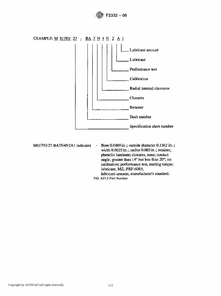
FIG. A27.2 Part Number
F2332 − 06
111Copyright by ASTM Int'l (all rights reserved);

A28. ANNULAR BALL BEARING FOR INSTRUMENTS AND PRECISION ROTATING COMPONENTS, ANGULAR CON-TACT, UNFLANGED, SEPARABLE AND STEPPED INNER RING, CORROSION-RESISTANT STEEL, ABEC 7P
A28.1 Requirements
A28.1.1 Design—All bearings described in this annex shallbe angular contact instrument bearings with an unflanged,separable, and stepped inner ring configuration (see Fig.A26.1).
A28.1.2 Material—The ball and ring material for thesebearings shall be corrosion-resistant steel 440C (UNS S44004)conforming to SAE-AMS-QQ-S-763.
A28.1.3 Tolerance Class— The tolerance class shall be inaccordance with the ABEC 7P tolerance tables of ABMAStandard 12.2. This tolerance class shall apply to all bearingsizes listed in Table A28.1.
A28.1.4 Boundary Dimensions—The boundary dimensionsshall be as specified by the dash number (Dash No.) in TableA28.1.
A28.1.5 Retainer—The retainer shall be as specified by thepart number designator (PN Des) in Table A28.2.
A28.1.6 Closures—Closures are not available for this typeof bearing. Part number designator N shall be used as shown inTable A28.3.
A28.1.7 Radial Internal Clearance or Contact Angle—Theradial internal clearance or contact angle shall be as specifiedby the part number designator in Table A28.4.
A28.1.8 Calibration— The calibration shall be as specifiedby the part number designator in Table A28.5.
A28.1.9 Performance Test—The performance test shall beas specified by the part number designator in Table A28.6.
A28.1.10 Lubrication:
A28.1.10.1 Lubricant—The lubricant shall be in accordancewith the specification indicated by the part number designatorin Table A28.7.
A28.1.10.2 Lubricant Amount—The amount of lubricantshall be as specified by the part number designator in TableA28.8.
A28.1.10.3 Barrier Coating— The barrier coating shall beapplied to bearings as specified by the part number designatorin Table A28.7.
A28.1.11 Part Number— The part number consists of thefollowing: prefix letter M; general specification number; num-ber of this specification sheet; dash number; and characters for:retainer, closures, radial internal clearance or contact angle,calibration, performance test, lubricant, and lubricant amount(see Fig. A28.2).
FIG. A28.1 Bearing Configuration
F2332 − 06
112Copyright by ASTM Int'l (all rights reserved);

TABLE A28.1 Boundary Dimensions, inches
DashNo.
Bored
ODD
WidthC
RadiusrA,B
-AA 0.0400 0.1250 0.0469 0.003-BA 0.0469 0.1562 0.0625 0.003-BB 0.0469 0.1562 0.0937 0.003-CA 0.0550 0.1875 0.0781 0.003-CB 0.0550 0.1875 0.1094 0.003-DA 0.0781 0.2500 0.0937 0.003-DB 0.0781 0.2500 0.1406 0.003-DC 0.0781 0.2500 0.1094 0.003-EA 0.0937 0.1875 0.0625 0.003-EB 0.0937 0.1875 0.0937 0.003-EC 0.0937 0.3125 0.1094 0.003-ED 0.0937 0.3125 0.1406 0.003-EE 0.0937 0.2500 0.1094 0.003-EF 0.0937 0.2883 0.0625 0.003-KG 0.0937 0.3125 0.0625 0.003-EH 0.0937 0.3125 0.1094 0.003-EJ 0.0937 0.3125 0.1406 0.003-EK 0.0937 0.4100 0.1094 0.003-FA 0.1250 0.2500 0.0937 0.003-FB 0.1250 0.2500 0.1094 0.003-FC 0.1250 0.3125 0.1094 0.003-FD 0.1250 0.3125 0.1406 0.003-FE 0.1250 0.3750 0.1094 0.005-FF 0.1250 0.3750 0.1406 0.005-FG 0.1250 0.3750 0.1562 0.012-FH 0.1250 0.4100 0.0937 0.003-FJ 0.1250 0.4100 0.1094 0.003-FK 0.1250 0.4250 0.0937 0.003-FL 0.1250 0.4250 0.1094 0.003-FM 0.1250 0.4375 0.1094 0.003-FN 0.1250 0.4375 0.1406 0.003-FP 0.1250 0.5000 0.1094 0.003-FR 0.1250 0.5000 0.1719 0.012-FT 0.1250 0.7500 0.1250 0.010-FV 0.1250 0.3750 0.0937 0.003-GA 0.1562 0.3125 0.1094 0.003-GB 0.1562 0.3125 0.1250 0.003-HA 0.1875 0.3125 0.1094 0.003-HB 0.1875 0.3125 0.1250 0.003-HC 0.1875 0.3750 0.1094 0.003-HD 0.1875 0.3750 0.1250 0.003-HE 0.1875 0.4100 0.1094 0.003-HF 0.1875 0.4250 0.1094 0.003-HG 0.1875 0.4375 0.1094 0.003-HH 0.1875 0.5000 0.1094 0.003-HJ 0.1875 0.5000 0.1562 0.012-HK 0.1875 0.5000 0.1960 0.012-HL 0.1875 0.7435 0.1960 0.012-HM 0.1875 0.7500 0.1960 0.012-HN 0.1875 0.8750 0.1960 0.012-JA 0.2500 0.3750 0.1250 0.003-JB 0.2500 0.5000 0.1094 0.003-JC 0.2500 0.5000 0.1250 0.005-JD 0.2500 0.5000 0.1875 0.005-JE 0.2500 0.6250 0.1960 0.012-JF 0.2500 0.7500 0.1960 0.012-JG 0.2500 0.7500 0.2188 0.016-JH 0.2500 0.7500 0.2812 0.016-JJ 0.2500 0.8750 0.1960 0.012-JK 0.2500 1.0000 0.1960 0.012-JL 0.2500 1.0480 0.1960 0.012-KA 0.3125 0.5000 0.1562 0.005-KB 0.3125 0.6250 0.1562 0.010-LA 0.3750 0.8750 0.2188 0.016-LB 0.3750 0.8750 0.2812 0.016-MA 0.5000 0.8750 0.2188 0.016-MG 0.5000 0.8750 0.2812 0.016-MC 0.5000 1.1250 0.2500 0.016-MD 0.5000 1.1250 0.3125 0.016-NA 0.6250 1.3750 0.2812 0.031-NB 0.6250 1.3750 0.3438 0.031
A Maximum shaft or housing fillet radius that bearing corners will clear.B Narrow face of rings shall have a maximum r value of one half the value listedprovided this quantity does not fall below 0.003 inches.
TABLE A28.2 Retainer
PN Des Type
7 phenolic-type laminateA ,B
8 vacuum-impregnated phenolicB ,C
9 nonporous, nonmetallicB
A Phenolic or other porous nonmetallic material.B Used for high-speed applications.C Phenolic or other porous nonmetallic material saturated with lubricant. Selectionof this choice dictates choosing manufacturer’s standard amount of lubricant.
TABLE A28.3 Closures
PN Des Number Type
N none none
TABLE A28.4 Radial Internal Clearance or Contact Angle
PN Des Range
1 0.0001 to 0.0003 in.2 0.0003 to 0.0005 in.3 14° or lessA
4 greater than 14° but less than 20°A
5 0.0005 to 0.0008 in.6 greater than 20°A
8 0.0008 to 0.0011 in.9 As specified in contract
A Angular contact bearing designations only.
TABLE A28.5 Calibration of Bore and Outside Diameter (OD)
PN Des Bore Increments OD Increments
N no calibration no calibrationA no calibration 0.00010B no calibration 0.00005C 0.00010 no calibrationD 0.00010 0.00010E 0.00010 0.00005F 0.00005 no calibrationG 0.00005 0.00010H 0.00005 0.00005
F2332 − 06
113Copyright by ASTM Int'l (all rights reserved);

TABLE A28.6 Performance Test
PN Des Type
1 manufacturer’s standard2 starting torqueA
A Starting torque limits from Table 2 of base document.
TABLE A28.7 Lubricant
PN Des Specification
P preservativeA
A MIL-PRF-6085B MIL-PRF-6085B
C DOD-L-81846D DOD-L-81846B
E MIL-PRF-23827F MIL-PRF-81322G MIL-G-81937H MIL-PRF-83261J MIL-S-81087C
K MIL-S-81087C
L MIL-DTL-53131, Grade 4M MIL-DTL-53131, Grade 6N MIL-DTL-53131, Grade 9Q MIL-DTL-53131, Grade 14R MIL-DTL-53131, Grade 40S As specified in contract
A PN Des “P” shall be used only with PN Des “P” in Table A28.8.B With barrier coat.C Canceled – lube no longer manufactured.
TABLE A28.8 Lubricant Amount
PN Des Quantity
P preservative amount as required byMIL-DTL-197
1 manufacturer’s standardA
2 oil per Table 5 of base document3 15 % grease4 25 % grease5 35 % grease6 45 % grease7 As specified in contract
A Grease: fill to minimum 25 %, maximum 40 % of bearing void. Oil: immerse andthen allow excess to drip off. The standard quantity of oil varies with each bearingsize.
F2332 − 06
114Copyright by ASTM Int'l (all rights reserved);

FIG. A28.2 Part Number
F2332 − 06
115Copyright by ASTM Int'l (all rights reserved);

A29. ANNULAR BALL BEARING FOR INSTRUMENTS AND PRECISION ROTATING COMPONENTS, ANGULAR CON-TACT, FLANGED, SEPARABLE, AND STEPPED INNER RING, CHROMIUM ALLOY STEEL, ABEC 5P
A29.1 Requirements
A29.1.1 Design—All bearings described in this annex shallbe angular contact instrument bearings with a flanged, sepa-rable, and stepped inner ring configuration (see Fig. A29.1).
A29.1.2 Material—The ball and ring material for thesebearings shall be chromium-alloy steel 52100(UNS G52986)conforming to SAE-AMS-6444.
A29.1.3 Tolerance Class— The tolerance class shall be inaccordance with the ABEC 5P tolerance tables of ABMAStandard 12.2. This tolerance class shall apply to all bearingsizes listed in Table A29.1.
A29.1.4 Boundary Dimensions—The boundary dimensionsshall be as specified by the dash number (Dash No.) in TableA29.1.
A29.1.5 Retainer—The retainer shall be as specified by thepart number designator (PN Des) in Table A29.2.
A29.1.6 Closures—Closures are not available for this typeof bearing. Part number designator N shall be used as shown inTable A29.3.
A29.1.7 Radial Internal Clearance or Contact Angle—Theradial internal clearance or contact angle shall be as specifiedby the part number designator in Table A29.4.
A29.1.8 Calibration— The calibration shall be as specifiedby the part number designator in Table A29.5.
A29.1.9 Performance Test—The performance test shall beas indicated by the part number designator in Table A29.6.
A29.1.10 Lubrication:
A29.1.10.1 Lubricant—The lubricant shall be in accordancewith the specification indicated by the part number designatorin Table A29.7.
A29.1.10.2 Lubricant Amount—The amount of lubricantshall be as specified by the part number designator in TableA29.8.
A29.1.10.3 Barrier Coating— The barrier coating shall beapplied to bearings as specified by the part number designatorin Table A29.7.
A29.1.11 Part Number— The part number consists of thefollowing: prefix letter M; general specification number; num-ber of this specification sheet; dash number; and characters for:retainer, closures, radial internal clearance or contact angle,calibration, performance test, lubricant, and lubricant amount(see Fig. A29.2).
FIG. A29.1 Bearing Configuration
F2332 − 06
116Copyright by ASTM Int'l (all rights reserved);

TABLE A29.1 Boundary Dimensions, inches
DashNo.
Bored
ODD
WidthC
FlangeODD1
FlangeWidth
C1
RadiusrA,B
-AA 0.0400 0.1250 0.0469 0.171 0.013 0.003-BA 0.0469 0.1562 0.0625 0.203 0.013 0.003-BB 0.0469 0.1562 0.0937 0.203 0.031 0.003-CA 0.0550 0.1875 0.0781 0.234 0.031 0.003-CB 0.0550 0.1875 0.1094 0.234 0.031 0.003-DA 0.0781 0.2500 0.0937 0.296 0.023 0.003-DB 0.0781 0.2500 0.1406 0.296 0.031 0.003-EA 0.0937 0.1875 0.0625 0.234 0.018 0.003-EB 0.0937 0.1875 0.0937 0.234 0.031 0.003-EC 0.0937 0.3125 0.1094 0.359 0.023 0.003-ED 0.0937 0.3125 0.1406 0.359 0.031 0.003-FA 0.1250 0.2500 0.0937 0.296 0.023 0.003-FB 0.1250 0.2500 0.1094 0.296 0.031 0.003-FC 0.1250 0.3125 0.1094 0.359 0.023 0.003-FD 0.1250 0.3125 0.1406 0.359 0.031 0.003-FE 0.1250 0.3750 0.1094 0.422 0.023 0.003-FF 0.1250 0.3750 0.1406 0.422 0.031 0.033-FG 0.1250 0.3750 0.1562 0.440 0.030 0.012-GA 0.1562 0.3125 0.1094 0.359 0.023 0.003-GB 0.1562 0.3125 0.1250 0.359 0.036 0.003-GD 0.1562 0.3125 0.1250 0.359 0.036 0.003-HA 0.1875 0.3750 0.1250 0.422 0.023 0.003-HB 0.1875 0.3750 0.1250 0.422 0.031 0.003-HC 0.1875 0.5000 0.1562 0.565 0.042 0.012-HD 0.1875 0.5000 0.1960 0.565 0.042 0.012-HE 0.1875 0.3125 0.1094 0.359 0.023 0.003-HF 0.1875 0.3125 0.1250 0.359 0.036 0.003-JA 0.2500 0.3750 0.1250 0.422 0.023 0.003-JB 0.2500 0.3750 0.1250 0.422 0.036 0.003-JC 0.2500 0.5000 0.1250 0.547 0.023 0.005-JD 0.2500 0.5000 0.1875 0.547 0.045 0.005-JE 0.2500 0.6250 0.1960 0.690 0.042 0.012-KA 0.3125 0.5000 0.1562 0.547 0.031 0.005-LA 0.3750 0.8750 0.2188 0.969 0.062 0.016-LB 0.3750 0.8750 0.2812 0.969 0.062 0.016-MA 0.5000 1.1250 0.2500 1.225 0.062 0.016-MB 0.5000 1.1250 0.3125 1.225 0.062 0.016
A Maximum shaft or housing fillet radius that bearing corners will clear.B Narrow face of rings shall have a maximum r value of one half the value listedprovided this quantity does not fall below 0.003 inches.
TABLE A29.2 Retainer
PN Des Type
7 phenolic-type laminateA ,B
8 vacuum-impregnated phenolicB ,C
9 nonporous, nonmetallicB
A Phenolic or other porous nonmetallic material.B Used for high-speed applications.C Phenolic or other porous nonmetallic material saturated with lubricant. Selectionof this choice dictates choosing manufacturer’s standard amount of lubricant.
TABLE A29.3 Closures
PN Des Number Type
N none none
TABLE A29.4 Radial Internal Clearance or Contact Angle
PN Des Range
1 0.0001 to 0.0003 in.2 0.0003 to 0.0005 in.3 14° or lessA
4 greater than 14° but less than 20°A
5 0.0005 to 0.0008 in.6 greater than 20°A
8 0.0008 to 0.0011 in.9 As specified in contract
A Angular contact bearing designations only.
TABLE A29.5 Calibration of Bore and Outside Diameter (OD)
PN Des Bore Increments OD Increments
N no calibration no calibrationA no calibration 0.00010B no calibration 0.00005C 0.00010 no calibrationD 0.00010 0.00010E 0.00010 0.00005F 0.00005 no calibrationG 0.00005 0.00010H 0.00005 0.00005
TABLE A29.6 Performance Test
PN Des Type
1 manufacturer’s standard2 starting torqueA
A Starting torque limits from Table 2 of base document.
TABLE A29.7 Lubricant
PN Des Specification
P preservativeA
A MIL-PRF-6085B MIL-PRF-6085B
C DOD-L-81846D DOD-L-81846B
E MIL-PRF-23827F MIL-PRF-81322G MIL-G-81937H MIL-PRF-83261J MIL-S-81087C
K MIL-S-81087C
L MIL-DTL-53131, Grade 4M MIL-DTL-53131, Grade 6N MIL-DTL-53131, Grade 9Q MIL-DTL-53131, Grade 14R MIL-DTL-53131, Grade 40S As specified in contract
A PN Des “P” shall be used only with PN Des “P” in Table A29.8.B With barrier coat.C Canceled – lube no longer manufactured.
F2332 − 06
117Copyright by ASTM Int'l (all rights reserved);

TABLE A29.8 Lubricant Amount
PN Des Quantity
P preservative amount as required byMIL-DTL-197
1 manufacturer’s standardA
2 oil per Table 5 of base document3 15 % grease4 25 % grease5 35 % grease6 45 % grease7 As specified in contract
A Grease: fill to minimum 25 %, maximum 40 % of bearing void. Oil: immerse andthen allow excess to drip off. The standard quantity of oil varies with each bearingsize.
FIG. A29.2 Part Number
F2332 − 06
118Copyright by ASTM Int'l (all rights reserved);

A30. ANNULAR BALL BEARING FOR INSTRUMENTS AND PRECISION ROTATING COMPONENTS, ANGULAR CON-TACT, FLANGED, SEPARABLE, AND STEPPED INNER RING, CHROMIUM ALLOY STEEL, ABEC 7P
A30.1 Requirements
A30.1.1 Design—All bearings described in this annex shallbe angular contact instrument bearings with a flanged, sepa-rable, and stepped inner ring configuration (see Fig. A30.1).
A30.1.2 Material—The ball and ring material for thesebearings shall be chromium-alloy steel 52100 (UNS G52986)conforming to SAE-AMS-6444.
A30.1.3 Tolerance Class— The tolerance class shall be inaccordance with the ABEC 7P tolerance tables of ABMAStandard 12.2. This tolerance class shall apply to all bearingsizes listed in Table A30.1.
A30.1.4 Boundary Dimensions—The boundary dimensionsshall be as specified by the dash number (Dash No.) in TableA30.1.
A30.1.5 Retainer—The retainer shall be as specified by thepart number designator (PN Des) in Table A30.2.
A30.1.6 Closures—Closures are not available for this typeof bearing. Part number designator N shall be used as shown inTable A30.3.
A30.1.7 Radial Internal Clearance or Contact Angle—Theradial internal clearance or contact angle shall be as specifiedby the part number designator in Table A30.4.
A30.1.8 Calibration— The calibration shall be as specifiedby the part number designator in Table A30.5.
A30.1.9 Performance Test—The performance test shall beas specified by the part number designator in Table A30.6.
A30.1.10 Lubrication:A30.1.10.1 Lubricant—The lubricant shall be in accordance
with the specification indicated by the part number designatorin Table A30.7.
FIG. A30.1 Bearing Configuration
TABLE A30.1 Boundary Dimensions, inches
DashNo.
Bored
ODD
WidthC
FlangeODD1
FlangeWidth
C1
RadiusrA,B
-AA 0.0400 0.1250 0.0469 0.171 0.013 0.003-BA 0.0469 0.1562 0.0625 0.203 0.013 0.003-BB 0.0469 0.1562 0.0937 0.203 0.031 0.003-CA 0.0550 0.1875 0.0781 0.234 0.031 0.003-CB 0.0550 0.1875 0.1094 0.234 0.031 0.003-DA 0.0781 0.2500 0.0937 0.296 0.023 0.003-DB 0.0781 0.2500 0.1406 0.296 0.031 0.003-EA 0.0937 0.1875 0.0625 0.234 0.018 0.003-EB 0.0937 0.1875 0.0937 0.234 0.031 0.003-EC 0.0937 0.3125 0.1094 0.359 0.023 0.003-ED 0.0937 0.3125 0.1406 0.359 0.031 0.003-FA 0.1250 0.2500 0.0937 0.296 0.023 0.003-FB 0.1250 0.2500 0.1094 0.296 0.031 0.003-FC 0.1250 0.3125 0.1094 0.359 0.023 0.003-FD 0.1250 0.3125 0.1406 0.359 0.031 0.003-FE 0.1250 0.3750 0.1094 0.422 0.023 0.003-FF 0.1250 0.3750 0.1406 0.422 0.031 0.033-FG 0.1250 0.3750 0.1562 0.440 0.030 0.012-GA 0.1562 0.3125 0.1094 0.359 0.023 0.003-GB 0.1562 0.3125 0.1250 0.359 0.036 0.003-GD 0.1562 0.3125 0.1250 0.359 0.036 0.003-HA 0.1875 0.3750 0.1250 0.422 0.023 0.003-HB 0.1875 0.3750 0.1250 0.422 0.031 0.003-HC 0.1875 0.5000 0.1562 0.565 0.042 0.012-HD 0.1875 0.5000 0.1960 0.565 0.042 0.012-HE 0.1875 0.3125 0.1094 0.359 0.023 0.003-HF 0.1875 0.3125 0.1250 0.359 0.036 0.003-JA 0.2500 0.3750 0.1250 0.422 0.023 0.003-JB 0.2500 0.3750 0.1250 0.422 0.036 0.003-JC 0.2500 0.5000 0.1250 0.547 0.023 0.005-JD 0.2500 0.5000 0.1875 0.547 0.045 0.005-JE 0.2500 0.6250 0.1960 0.690 0.042 0.012-KA 0.3125 0.5000 0.1562 0.547 0.031 0.005-LA 0.3750 0.8750 0.2188 0.969 0.062 0.016-LB 0.3750 0.8750 0.2812 0.969 0.062 0.016-MA 0.5000 1.1250 0.2500 1.225 0.062 0.016-MB 0.5000 1.1250 0.3125 1.225 0.062 0.016
A Maximum shaft or housing fillet radius that bearing corners will clear.B Narrow face of rings shall have a maximum r value of one-half the value listedprovided this quantity does not fall below 0.003 inches.
F2332 − 06
119Copyright by ASTM Int'l (all rights reserved);

A30.1.10.2 Lubricant Amount—The amount of lubricantshall be as specified by the part number designator in TableA30.8.
A30.1.10.3 Barrier Coating— The barrier coating shall beapplied to bearings as specified by the part number designatorin Table A30.7.
A30.1.11 Part Number— The part number consists of thefollowing: prefix letter M; general specification number; num-
ber of this specification sheet; dash number; and characters for:retainer, closures, radial internal clearance or contact angle,calibration, performance test, lubricant, and lubricant amount(see Fig. A30.2).
TABLE A30.2 Retainer
PN Des Type
7 phenolic-type laminateA ,B
8 vacuum-impregnated phenolicB ,C
9 nonporous, nonmetallicB
A Phenolic or other porous nonmetallic material.B Used for high-speed applications.C Phenolic or other porous nonmetallic material saturated with lubricant. Selectionof this choice dictates choosing manufacturer’s standard amount of lubricant.
TABLE A30.3 Closures
PN Des Number Type
N none none
TABLE A30.4 Radial Internal Clearance or Contact Angle
PN Des Range
1 0.0001 to 0.0003 in.2 0.0003 to 0.0005 in.3 14° or lessA
4 greater than 14° but less than 20°A
5 0.0005 to 0.0008 in.6 greater than 20°A
8 0.0008 to 0.0011 in.9 As specified in contract
A Angular contact bearing designations only.
TABLE A30.5 Calibration of Bore and Outside Diameter (OD)
PN Des Bore Increments OD Increments
N no calibration no calibrationA no calibration 0.00010B no calibration 0.00005C 0.00010 no calibrationD 0.00010 0.00010E 0.00010 0.00005F 0.000 05 no calibrationG 0.00005 0.00010H 0.00005 0.00005
TABLE A30.6 Performance Test
PN Des Type
1 manufacturer’s standard2 starting torqueA
A Starting torque limits from Table 2 of base document.
TABLE A30.7 Lubricant
PN Des Specification
P preservativeA
A MIL-PRF-6085B MIL-PRF-6085B
C DOD-L-81846D DOD-L-81846B
E MIL-PRF-23827F MIL-PRF-81322G MIL-G-81937H MIL-PRF-83261J MIL-S-81087C
K MIL-S-81087C
L MIL-DTL-53131, Grade 4M MIL-DTL-53131, Grade 6N MIL-DTL-53131, Grade 9Q MIL-DTL-53131, Grade 14R MIL-DTL-53131, Grade 40S As specified in contract
A PN Des “P” shall be used only with PN Des “P” in Table A30.8.B With barrier coat.C Canceled – lube no longer manufactured.
TABLE A30.8 Lubricant Amount
PN Des Quantity
P preservative amount as required byMIL-DTL-197
1 manufacturer’s standardA
2 oil per Table 5 of base document3 15 % grease4 25 % grease5 35 % grease6 45 % grease7 As specified in contract
A Grease: fill to minimum 25 %, maximum 40 % of bearing void. Oil: immerse andthen allow excess to drip off. The standard quantity of oil varies with each bearingsize.
F2332 − 06
120Copyright by ASTM Int'l (all rights reserved);

A31. ANNULAR BALL BEARING FOR INSTRUMENTS AND PRECISION ROTATING COMPONENTS, ANGULAR CON-TACT, FLANGED, SEPARABLE, AND STEPPED INNER RING, CORROSION-RESISTANT STEEL, ABEC 5P
A31.1 Requirements
A31.1.1 Design—All bearings described in this annex shallbe angular contact instrument bearings with a flanged, sepa-rable, and stepped inner ring configuration (see Fig. A31.1).
A31.1.2 Material—The ball and ring material for thesebearings shall be corrosion-resistant steel 440C (UNS S44004)conforming to SAE-AMS-QQ-S-763.
A31.1.3 Tolerance Class— The tolerance class shall be inaccordance with the ABEC 5P tolerance tables of ABMAStandard 12.2. This tolerance class shall apply to all bearingsizes listed in Table A31.1.
A31.1.4 Boundary Dimensions—The boundary dimensionsshall be as specified by the dash number (Dash No.) in TableA31.1.
A31.1.5 Retainer—The retainer shall be as specified by thepart number designator (PN Des) in Table A31.2.
A31.1.6 Closures—Closures are not available for this typeof bearing. Part number designator N shall be used as shown inTable A31.3.
A31.1.7 Radial Internal Clearance or Contact Angle—Theradial internal clearance or contact angle shall be as specifiedby the part number designator in Table A31.4.
FIG. A30.2 Part Number
F2332 − 06
121Copyright by ASTM Int'l (all rights reserved);
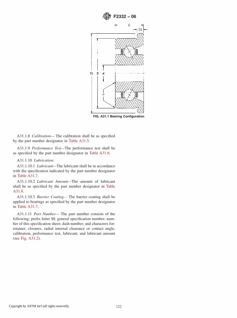
A31.1.8 Calibration— The calibration shall be as specifiedby the part number designator in Table A31.5.
A31.1.9 Performance Test—The performance test shall beas specified by the part number designator in Table A31.6.
A31.1.10 Lubrication:
A31.1.10.1 Lubricant—The lubricant shall be in accordancewith the specification indicated by the part number designatorin Table A31.7.
A31.1.10.2 Lubricant Amount—The amount of lubricantshall be as specified by the part number designator in TableA31.8.
A31.1.10.3 Barrier Coating— The barrier coating shall beapplied to bearings as specified by the part number designatorin Table A31.7.
A31.1.11 Part Number— The part number consists of thefollowing: prefix letter M; general specification number; num-ber of this specification sheet; dash number; and characters for:retainer, closures, radial internal clearance or contact angle,calibration, performance test, lubricant, and lubricant amount(see Fig. A31.2).
FIG. A31.1 Bearing Configuration
F2332 − 06
122Copyright by ASTM Int'l (all rights reserved);

TABLE A31.1 Boundary Dimensions, inches
DashNo.
Bored
ODD
WidthC
FlangeODD1
FlangeWidth
C1
RadiusrA,B
-AA 0.0400 0.1250 0.0469 0.171 0.013 0.003-BA 0.0469 0.1562 0.0625 0.203 0.013 0.003-BB 0.0469 0.1562 0.0937 0.203 0.031 0.003-CA 0.0550 0.1875 0.0781 0.234 0.031 0.003-CB 0.0550 0.1875 0.1094 0.234 0.031 0.003-DA 0.0781 0.2500 0.0937 0.296 0.023 0.003-DB 0.0781 0.2500 0.1406 0.296 0.031 0.003-EA 0.0937 0.1875 0.0625 0.234 0.018 0.003-EB 0.0937 0.1875 0.0937 0.234 0.031 0.003-EC 0.0937 0.3125 0.1094 0.359 0.023 0.003-ED 0.0937 0.3125 0.1406 0.359 0.031 0.003-FA 0.1250 0.2500 0.0937 0.296 0.023 0.003-FB 0.1250 0.2500 0.1094 0.296 0.031 0.003-FC 0.1250 0.3125 0.1094 0.359 0.023 0.003-FD 0.1250 0.3125 0.1406 0.359 0.031 0.003-FE 0.1250 0.3750 0.1094 0.422 0.023 0.003-FF 0.1250 0.3750 0.1406 0.422 0.031 0.033-FG 0.1250 0.3750 0.1562 0.440 0.030 0.012-GA 0.1562 0.3125 0.1094 0.359 0.023 0.003-GB 0.1562 0.3125 0.1250 0.359 0.036 0.003-GD 0.1562 0.3125 0.1250 0.359 0.036 0.003-HA 0.1875 0.3750 0.1250 0.422 0.023 0.003-HB 0.1875 0.3750 0.1250 0.422 0.031 0.003-HC 0.1875 0.5000 0.1562 0.565 0.042 0.012-HD 0.1875 0.5000 0.1960 0.565 0.042 0.012-HE 0.1875 0.3125 0.1094 0.359 0.023 0.003-HF 0.1875 0.3125 0.1250 0.359 0.036 0.003-JA 0.2500 0.3750 0.1250 0.422 0.023 0.003-JB 0.2500 0.3750 0.1250 0.422 0.036 0.003-JC 0.2500 0.5000 0.1250 0.547 0.023 0.005-JD 0.2500 0.5000 0.1875 0.547 0.045 0.005-JE 0.2500 0.6250 0.1960 0.690 0.042 0.012-KA 0.3125 0.5000 0.1562 0.547 0.031 0.005-LA 0.3750 0.8750 0.2188 0.969 0.062 0.016-LB 0.3750 0.8750 0.2812 0.969 0.062 0.016-MA 0.5000 1.1250 0.2500 1.225 0.062 0.016-MB 0.5000 1.1250 0.3125 1.225 0.062 0.016
A Maximum shaft or housing fillet radius that bearing corners will clear.B Narrow face of rings shall have a maximum r value of one half the value listedprovided this quantity does not fall below 0.003 inches.
TABLE A31.2 Retainer
PN Des Type
7 phenolic-type laminateA ,B
8 vacuum-impregnated phenolicB ,C
9 nonporous, nonmetallicB
A Phenolic or other porous nonmetallic material.B Used for high-speed applications.C Phenolic or other porous nonmetallic material saturated with lubricant. Selectionof this choice dictates choosing manufacturer’s standard amount of lubricant.
TABLE A31.3 Closures
PN Des Number Type
N none none
TABLE A31.4 Radial Internal Clearance or Contact Angle
PN Des Range
1 0.0001 to 0.0003 in.2 0.0003 to 0.0005 in.3 14° or lessA
4 greater than 14° but less than 20°A
5 0.0005 to 0.0008 in.6 greater than 20°A
8 0.0008 to 0.0011 in.9 As specified in contract
A Angular contact bearing designations only.
TABLE A31.5 Calibration of Bore and Outside Diameter (OD)
PN Des Bore Increments OD Increments
N no calibration no calibrationA no calibration 0.00010B no calibration 0.00005C 0.00010 no calibrationD 0.00010 0.00010E 0.00010 0.00005F 0.00005 no calibrationG 0.00005 0.00010H 0.00005 0.00005
TABLE A31.6 Performance Test
PN Des Type
1 manufacturer’s standard2 starting torqueA
A Starting torque limits from Table 2 of base document.
F2332 − 06
123Copyright by ASTM Int'l (all rights reserved);

TABLE A31.7 Lubricant
PN Des Specification
P preservativeA
A MIL-PRF-6085B MIL-PRF-6085B
C DOD-L-81846D DOD-L-81846B
E MIL-PRF-23827F MIL-PRF-81322G MIL-G-81937H MIL-PRF-83261J MIL-S-81087C
K MIL-S-81087C
L MIL-DTL-53131, Grade 4M MIL-DTL-53131, Grade 6N MIL-DTL-53131, Grade 9Q MIL-DTL-53131, Grade 14R MIL-DTL-53131, Grade 40S As specified in contract
A PN Des “P” shall be used only with PN Des “P” in Table A31.8.B With barrier coat.C Canceled – lube no longer manufactured.
TABLE A31.8 Lubricant Amount
PN Des Quantity
P preservative amount as required byMIL-DTL-197
1 manufacturer’s standardA
2 oil per Table 5 of base document3 15 % grease4 25 % grease5 35 % grease6 45 % grease7 As specified in contract
A Grease: fill to minimum 25 %, maximum 40 % of bearing void. Oil: immerse andthen allow excess to drip off. The standard quantity of oil varies with each bearingsize.
F2332 − 06
124Copyright by ASTM Int'l (all rights reserved);

A32. ANNULAR BALL BEARING FOR INSTRUMENTS AND PRECISION ROTATING COMPONENTS, ANGULAR CON-TACT, FLANGED, SEPARABLE, AND STEPPED INNER RING, CORROSION-RESISTANT STEEL, ABEC 7P
A32.1 Requirements
A32.1.1 Design—All bearings described in this annex shallbe angular contact instrument bearings with a flanged, sepa-rable, and stepped inner ring configuration (see Fig. A32.1).
A32.1.2 Material—The ball and ring material for thesebearings shall be corrosion-resistant steel 440C (UNS S44004)conforming to SAE-AMS-QQ-S-763.
A32.1.3 Tolerance Class— The tolerance class shall be inaccordance with the ABEC 7P tolerance tables of ABMAStandard 12.2. This tolerance class shall apply to all bearingsizes listed in Table A32.1.
A32.1.4 Boundary Dimensions—The boundary dimensionsshall be as specified by the dash number (Dash No.) in TableA32.1.
A32.1.5 Retainer—The retainer shall be as specified by thepart number designator (PN Des) in Table A32.2.
A32.1.6 Closures—Closures are not available for this typeof bearing. Part number designation N shall be used as shownin Table A32.3.
A32.1.7 Radial Internal Clearance or Contact Angle—Theradial internal clearance or contact angle shall be as specifiedby the part number designator in Table A32.4.
FIG. A31.2 Part Number
F2332 − 06
125Copyright by ASTM Int'l (all rights reserved);

A32.1.8 Calibration— The calibration shall be as specifiedby the part number designator in Table A32.5.
A32.1.9 Performance Test—The performance test shall beas specified by the part number designator in Table A32.6.
A32.1.10 Lubrication:
A32.1.10.1 Lubricant—The lubricant shall be in accordancewith the specification indicated by the part number designatorin Table A32.7.
A32.1.10.2 Lubricant Amount—The amount of lubricantshall be as specified by the part number designator in TableA32.8.
A32.1.10.3 Barrier Coating— The barrier coating shall beapplied to bearings as specified by the part number designatorin Table A32.7.
A32.1.11 Part Number— The part number consists of thefollowing: prefix letter M; general specification number; num-ber of this specification sheet; dash number; and characters for:retainer, closures, radial internal clearance or contact angle,calibration, performance test, lubricant, and lubricant amount(see Fig. A32.2).
FIG. A32.1 Bearing Configuration
F2332 − 06
126Copyright by ASTM Int'l (all rights reserved);

TABLE A32.1 Boundary Dimensions, inches
DashNo.
Bored
ODD
WidthC
FlangeODD1
FlangeWidth
C1
RadiusrA,B
-AA 0.0400 0.1250 0.0469 0.171 0.013 0.003-BA 0.0469 0.1562 0.0625 0.203 0.013 0.003-BB 0.0469 0.1562 0.0937 0.203 0.031 0.003-CA 0.0550 0.1875 0.0781 0.234 0.031 0.003-CB 0.0550 0.1875 0.1094 0.234 0.031 0.003-DA 0.0781 0.2500 0.0937 0.296 0.023 0.003-DB 0.0781 0.2500 0.1406 0.296 0.031 0.003-EA 0.0937 0.1875 0.0625 0.234 0.018 0.003-EB 0.0937 0.1875 0.0937 0.234 0.031 0.003-EC 0.0937 0.3125 0.1094 0.359 0.023 0.003-ED 0.0937 0.3125 0.1406 0.359 0.031 0.003-FA 0.1250 0.2500 0.0937 0.296 0.023 0.003-FB 0.1250 0.2500 0.1094 0.296 0.031 0.003-FC 0.1250 0.3125 0.1094 0.359 0.023 0.003-FD 0.1250 0.3125 0.1406 0.359 0.031 0.003-FE 0.1250 0.3750 0.1094 0.422 0.023 0.003-FF 0.1250 0.3750 0.1406 0.422 0.031 0.033-FG 0.1250 0.3750 0.1562 0.440 0.030 0.012-GA 0.1562 0.3125 0.1094 0.359 0.023 0.003-GB 0.1562 0.3125 0.1250 0.359 0.036 0.003-GD 0.1562 0.3125 0.1250 0.359 0.036 0.003-HA 0.1875 0.3750 0.1250 0.422 0.023 0.003-HB 0.1875 0.3750 0.1250 0.422 0.031 0.003-HC 0.1875 0.5000 0.1562 0.565 0.042 0.012-HD 0.1875 0.5000 0.1960 0.565 0.042 0.012-HE 0.1875 0.3125 0.1094 0.359 0.023 0.003-HF 0.1875 0.3125 0.1250 0.359 0.036 0.003-JA 0.2500 0.3750 0.1250 0.422 0.023 0.003-JB 0.2500 0.3750 0.1250 0.422 0.036 0.003-JC 0.2500 0.5000 0.1250 0.547 0.023 0.005-JD 0.2500 0.5000 0.1875 0.547 0.045 0.005-JE 0.2500 0.6250 0.1960 0.690 0.042 0.012-KA 0.3125 0.5000 0.1562 0.547 0.031 0.005-LA 0.3750 0.8750 0.2188 0.969 0.062 0.016-LB 0.3750 0.8750 0.2812 0.969 0.062 0.016-MA 0.5000 1.1250 0.2500 1.225 0.062 0.016-MB 0.5000 1.1250 0.3125 1.225 0.062 0.016
A Maximum shaft or housing fillet radius that bearing corners will clear.B Narrow face of rings shall have a maximum r value of one half the value listedprovided this quantity does not fall below 0.003 inches.
TABLE A32.2 Retainer
PN Des Type
7 phenolic-type laminateA ,B
8 vacuum-impregnated phenolicB ,C
9 nonporous, nonmetallicB
A Phenolic or other porous nonmetallic material.B Used for high-speed applications.C Phenolic or other porous nonmetallic material saturated with lubricant. Selectionof this choice dictates choosing manufacturer’s standard amount of lubricant.
TABLE A32.3 Closures
PN Des Number Type
N none none
TABLE A32.4 Radial Internal Clearance or Contact Angle
PN Des Ranges
1 0.0001 to 0.0003 in.2 0.0003 to 0.0005 in.3 14° or lessA
4 greater than 14° but less than 20°A
5 0.0005 to 0.0008 in.6 greater than 20°A
8 0.0008 to 0.0011 in.9 As specified in contract
A Angular contact bearing designations only.
TABLE A32.5 Calibration of Bore and Outside Diameter (OD)
PN Des Bore Increments OD Increments
N no calibration no calibrationA no calibration 0.00010B no calibration 0.00005C 0.00010 no calibrationD 0.00010 0.00010E 0.00010 0.00005F 0.00005 no calibrationG 0.00005 0.00010H 0.00005 0.00005
TABLE A32.6 Performance Test
PN Des Type
1 manufacturer’s standard2 starting torqueA
A Starting torque limits from Table 2 of base document.
F2332 − 06
127Copyright by ASTM Int'l (all rights reserved);

TABLE A32.7 Lubricant
PN Des Specification
P preservativeA
A MIL-PRF-6085B MIL-PRF-6085B
C DOD-L-81846D DOD-L-81846B
E MIL-PRF-23827F MIL-PRF-81322G MIL-G-81937H MIL-PRF-83261J MIL-S-81087C
K MIL-S-81087C
L MIL-DTL-53131, Grade 4M MIL-DTL-53131, Grade 6N MIL-DTL-53131, Grade 9Q MIL-DTL-53131, Grade 14R MIL-DTL-53131, Grade 40S As specified in contract
A PN Des “P” shall be used only with PN Des “P” in Table A32.8.B With barrier coat.C Canceled – lube no longer manufactured.
TABLE A32.8 Lubricant Amount
PN Des Quantity
P preservative amount as required byMIL-DTL-197
1 manufacturer’s standardA
2 oil per Table 5 of base document3 15 % grease4 25 % grease5 35 % grease6 45 % grease7 As specified in contract
A Grease: fill to minimum 25 %, maximum 40 % of bearing void. Oil: immerse andthen allow excess to drip off. The standard quantity of oil varies with each bearingsize.
F2332 − 06
128Copyright by ASTM Int'l (all rights reserved);

A33. ANNULAR BALL BEARING FOR INSTRUMENTS AND PRECISION ROTATING COMPONENTS, ANGULAR CON-TACT, UNFLANGED, NONSEPARABLE, AND STEPPED INNER RING, CHROMIUM ALLOY STEEL, ABEC 5P
A33.1 Requirements
A33.1.1 Design—All bearings described in this annex shallbe angular contact instrument bearings with an unflanged,nonseparable, and stepped inner ring configuration (see Fig.A33.1).
A33.1.2 Material—The ball and ring material for thesebearings shall be chromium-alloy steel 52100 (UNS G52986)conforming to SAE-AMS-6444.
A33.1.3 Tolerance Class— The tolerance class shall be inaccordance with the ABEC 5P tolerance tables of ABMAStandard 12.2. This tolerance class shall apply to all bearingsizes listed in Table A33.1.
A33.1.4 Boundary Dimensions—The boundary dimensionsshall be as specified by the dash number (Dash No.) in TableA33.1.
A33.1.5 Retainer—The retainer shall be as specified by thepart number designator (PN Des) in Table A33.2.
A33.1.6 Closures—Closures are not available for this typeof bearing. Part number designator N shall be used as shown inTable A33.3.
A33.1.7 Radial Internal Clearance or Contact Angle—Theradial internal clearance or contact angle shall be as specifiedby the part number designator in Table A33.4.
FIG. A32.2 Part Number
F2332 − 06
129Copyright by ASTM Int'l (all rights reserved);

A33.1.8 Calibration— The calibration shall be as specifiedby the part number designator in Table A33.5.
A33.1.9 Performance Test—The performance test shall beas specified by the part number designator in Table A33.6.
A33.1.10 Lubrication:A33.1.10.1 Lubricant—The lubricant shall be in accordance
with the specification indicated by the part number designatorin Table A33.7.
A33.1.10.2 Lubricant Amount—The amount of lubricantshall be as specified by the part number designator in TableA33.8.
A33.1.10.3 Barrier Coating— The barrier coating shall beapplied to bearings as specified by the part number designatorin Table A33.7.
A33.1.11 Part Number— The part number consists of thefollowing: prefix letter M; general specification number; num-ber of this specification sheet; dash number; and characters for:retainer, closures, radial internal clearance or contact angle,calibration, performance test, lubricant, and lubricant amount(see Fig. A33.2).
FIG. A33.1 Bearing Configuration
F2332 − 06
130Copyright by ASTM Int'l (all rights reserved);

TABLE A33.1 Boundary Dimensions, inches
DashNo.
Bored
ODD
WidthC
RadiusrA,B
-AA 0.0400 0.1250 0.0469 0.003-BA 0.0469 0.1562 0.0625 0.003-BB 0.0469 0.1562 0.0937 0.003-CA 0.0550 0.1875 0.0781 0.003-CB 0.0550 0.1875 0.1094 0.003-DA 0.0781 0.2500 0.0937 0.003-DB 0.0781 0.2500 0.1406 0.003-DC 0.0781 0.2500 0.1094 0.003-EA 0.0937 0.1875 0.0625 0.003-EB 0.0937 0.1875 0.0937 0.003-EC 0.0937 0.3125 0.1094 0.003-ED 0.0937 0.3125 0.1406 0.003-EE 0.0937 0.2500 0.1094 0.003-EF 0.0937 0.2883 0.0625 0.003-KG 0.0937 0.3125 0.0625 0.003-EH 0.0937 0.3125 0.1094 0.003-EJ 0.0937 0.3125 0.1406 0.003-EK 0.0937 0.4100 0.1094 0.003-FA 0.1250 0.2500 0.0937 0.003-FB 0.1250 0.2500 0.1094 0.003-FC 0.1250 0.3125 0.1094 0.003-FD 0.1250 0.3125 0.1406 0.003-FE 0.1250 0.3750 0.1094 0.005-FF 0.1250 0.3750 0.1406 0.005-FG 0.1250 0.3750 0.1562 0.012-FH 0.1250 0.4100 0.0937 0.003-FJ 0.1250 0.4100 0.1094 0.003-FK 0.1250 0.4250 0.0937 0.003-FL 0.1250 0.4250 0.1094 0.003-FM O.1250 0.4375 0.1094 0.003-FN 0.1250 0.4375 0.1406 0.003-FP 0.1250 0.5000 0.1094 0.003-FR 0.1250 0.5000 0.1719 0.012-FT 0.1250 0.7500 0.1250 0.010-FV 0.1250 0.3750 0.0937 0.003-GA 0.1562 0.3125 0.1094 0.003-GB 0.1562 0.3125 0.1250 0.003-HA 0.1875 0.3125 0.1094 0.003-HB 0.1875 0.3125 0.1250 0.003-HC 0.1875 0.3750 0.1094 0.003-HD 0.1875 0.3750 0.1250 0.003-HE 0.1875 0.4100 0.1094 0.003-HF 0.1875 0.4250 0.1094 0.003-HG 0.1875 0.4375 0.1094 0.003-HH 0.1875 0.5000 0.1094 0.003-HJ 0.1875 0.5000 0.1562 0.012-HK 0.1875 0.5000 0.1960 0.012-HL 0.1875 0.7435 0.1960 0.012-HM 0.1875 0.7500 0.1960 0.012-HN 0.1875 0.8750 0.1960 0.012-JA 0.2500 0.3750 0.1250 0.003-JB 0.2500 0.5000 0.1094 0.003-JC 0.2500 0.5000 0.1250 0.005-JD 0.2500 0.5000 0.1875 0.005-JE 0.2500 0.6250 0.1960 0.012-JF 0.2500 0.7500 0.1960 0.012-JG 0.2500 0.7500 0.2188 0.016-JH 0.2500 0.7500 0.2812 0.016-JJ 0.2500 0.8750 0.1960 0.012-JK 0.2500 1.0000 0.1960 0.012-JL 0.2500 1.0480 0.1960 0.012-KA 0.3125 0.5000 0.1562 0.005-KB 0.3125 0.6250 0.1562 0.010-LA 0.3750 0.8750 0.2188 0.016-LB 0.3750 0.8750 0.2812 0.016-MA 0.5000 0.8750 0.2188 0.016-MG 0.5000 0.8750 0.2812 0.016-MC 0.5000 1.1250 0.2500 0.016-MD 0.5000 1.1250 0.3125 0.016-NA 0.6250 1.3750 0.2812 0.031-NB 0.6250 1.3750 0.3438 0.031
A Maximum shaft or housing fillet radius that bearing corners will clear.B Narrow face of rings shall have a maximum r value of one half the value listedprovided this quantity does not fall below 0.003 inches.
TABLE A33.2 Retainer
PN Des Type
0 no retainer, full complement6 PTFE toroidsA
7 phenolic-type laminateB ,C
8 vacuum-impregnated phenolicC ,D
9 nonporous, nonmetallicC
A PTFE (polytetrafluoroethylene).B Phenolic or other porous nonmetallic material.C Used for high-speed applications.D Phenolic or other porous nonmetallic material saturated with lubricant. Selectionof this choice dictates choosing manufacturer’s standard amount of lubricant.
TABLE A33.3 Closures
PN Des Number Type
N none none
TABLE A33.4 Radial Internal Clearance or Contact Angle
PN Des Range
1 0.0001 to 0.0003 in.2 0.0003 to 0.0005 in.3 14° or lessA
4 greater than 14° but less than 20°A
5 0.0005 to 0.0008 in.6 greater than 20°A
8 0.0008 to 0.0011 in.9 As specified in contract
A Angular contact bearing designations only.
TABLE A33.5 Calibration of Bore and Outside Diameter (OD)
PN Des Bore Increments OD Increments
N no calibration no calibrationA no calibration 0.00010B no calibration 0.00005C 0.00010 no calibrationD 0.00010 0.00010E 0.00010 0.00005F 0.00005 no calibrationG 0.00005 0.00010H 0.00005 0.00005
F2332 − 06
131Copyright by ASTM Int'l (all rights reserved);
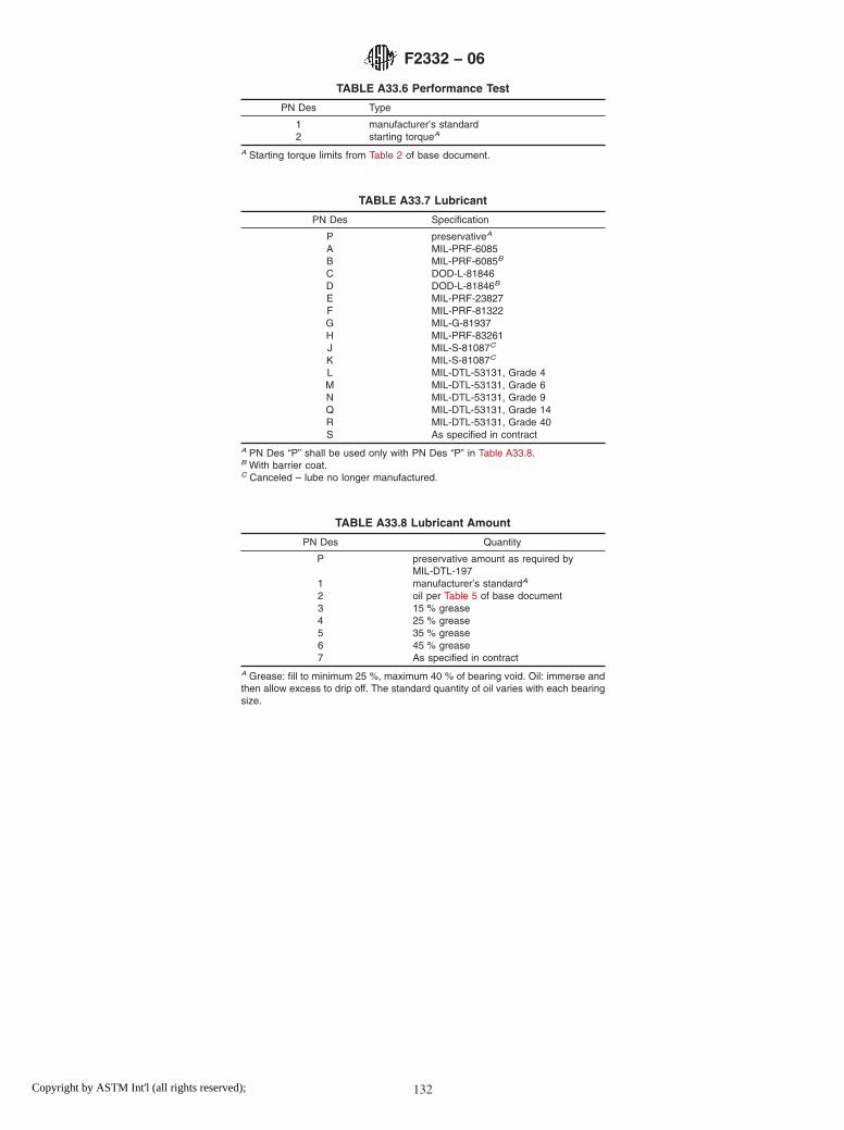
TABLE A33.6 Performance Test
PN Des Type
1 manufacturer’s standard2 starting torqueA
A Starting torque limits from Table 2 of base document.
TABLE A33.7 Lubricant
PN Des Specification
P preservativeA
A MIL-PRF-6085B MIL-PRF-6085B
C DOD-L-81846D DOD-L-81846B
E MIL-PRF-23827F MIL-PRF-81322G MIL-G-81937H MIL-PRF-83261J MIL-S-81087C
K MIL-S-81087C
L MIL-DTL-53131, Grade 4M MIL-DTL-53131, Grade 6N MIL-DTL-53131, Grade 9Q MIL-DTL-53131, Grade 14R MIL-DTL-53131, Grade 40S As specified in contract
A PN Des “P” shall be used only with PN Des “P” in Table A33.8.B With barrier coat.C Canceled – lube no longer manufactured.
TABLE A33.8 Lubricant Amount
PN Des Quantity
P preservative amount as required byMIL-DTL-197
1 manufacturer’s standardA
2 oil per Table 5 of base document3 15 % grease4 25 % grease5 35 % grease6 45 % grease7 As specified in contract
A Grease: fill to minimum 25 %, maximum 40 % of bearing void. Oil: immerse andthen allow excess to drip off. The standard quantity of oil varies with each bearingsize.
F2332 − 06
132Copyright by ASTM Int'l (all rights reserved);

FIG. A33.2 Part Number
F2332 − 06
133Copyright by ASTM Int'l (all rights reserved);
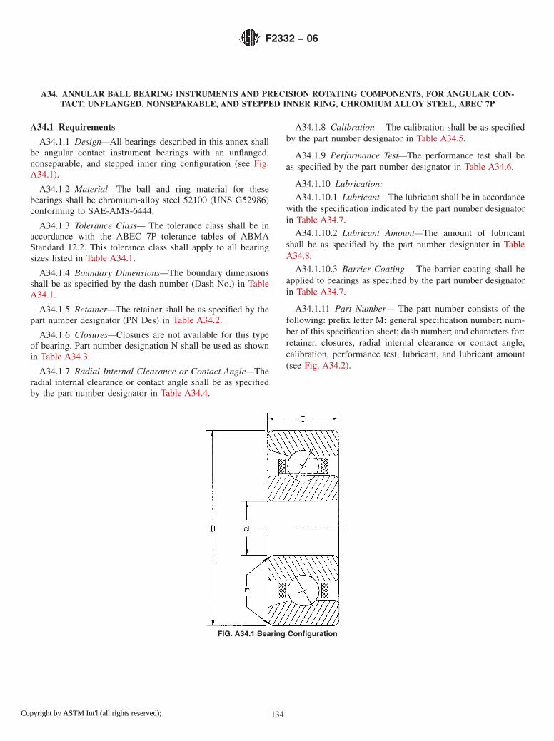
A34. ANNULAR BALL BEARING INSTRUMENTS AND PRECISION ROTATING COMPONENTS, FOR ANGULAR CON-TACT, UNFLANGED, NONSEPARABLE, AND STEPPED INNER RING, CHROMIUM ALLOY STEEL, ABEC 7P
A34.1 Requirements
A34.1.1 Design—All bearings described in this annex shallbe angular contact instrument bearings with an unflanged,nonseparable, and stepped inner ring configuration (see Fig.A34.1).
A34.1.2 Material—The ball and ring material for thesebearings shall be chromium-alloy steel 52100 (UNS G52986)conforming to SAE-AMS-6444.
A34.1.3 Tolerance Class— The tolerance class shall be inaccordance with the ABEC 7P tolerance tables of ABMAStandard 12.2. This tolerance class shall apply to all bearingsizes listed in Table A34.1.
A34.1.4 Boundary Dimensions—The boundary dimensionsshall be as specified by the dash number (Dash No.) in TableA34.1.
A34.1.5 Retainer—The retainer shall be as specified by thepart number designator (PN Des) in Table A34.2.
A34.1.6 Closures—Closures are not available for this typeof bearing. Part number designation N shall be used as shownin Table A34.3.
A34.1.7 Radial Internal Clearance or Contact Angle—Theradial internal clearance or contact angle shall be as specifiedby the part number designator in Table A34.4.
A34.1.8 Calibration— The calibration shall be as specifiedby the part number designator in Table A34.5.
A34.1.9 Performance Test—The performance test shall beas specified by the part number designator in Table A34.6.
A34.1.10 Lubrication:
A34.1.10.1 Lubricant—The lubricant shall be in accordancewith the specification indicated by the part number designatorin Table A34.7.
A34.1.10.2 Lubricant Amount—The amount of lubricantshall be as specified by the part number designator in TableA34.8.
A34.1.10.3 Barrier Coating— The barrier coating shall beapplied to bearings as specified by the part number designatorin Table A34.7.
A34.1.11 Part Number— The part number consists of thefollowing: prefix letter M; general specification number; num-ber of this specification sheet; dash number; and characters for:retainer, closures, radial internal clearance or contact angle,calibration, performance test, lubricant, and lubricant amount(see Fig. A34.2).
FIG. A34.1 Bearing Configuration
F2332 − 06
134Copyright by ASTM Int'l (all rights reserved);

TABLE A34.1 Boundary Dimensions, inches
DashNo.
Bored
ODD
WidthC
RadiusrA,B
-AA 0.0400 0.1250 0.0469 0.003-BA 0.0469 0.1562 0.0625 0.003-BB 0.0469 0.1562 0.0937 0.003-CA 0.0550 0.1875 0.0781 0.003-CB 0.0550 0.1875 0.1094 0.003-DA 0.0781 0.2500 0.0937 0.003-DB 0.0781 0.2500 0.1406 0.003-DC 0.0781 0.2500 0.1094 0.003-EA 0.0937 0.1875 0.0625 0.003-EB 0.0937 0.1875 0.0937 0.003-EC 0.0937 0.3125 0.1094 0.003-ED 0.0937 0.3125 0.1406 0.003-EE 0.0937 0.2500 0.1094 0.003-EF 0.0937 0.2883 0.0625 0.003-KG 0.0937 0.3125 0.0625 0.003-EH 0.0937 0.3125 0.1094 0.003-EJ 0.0937 0.3125 0.1406 0.003-EK 0.0937 0.4100 0.1094 0.003-FA 0.1250 0.2500 0.0937 0.003-FB 0.1250 0.2500 0.1094 0.003-FC 0.1250 0.3125 0.1094 0.003-FD 0.1250 0.3125 0.1406 0.003-FE 0.1250 0.3750 0.1094 0.005-FF 0.1250 0.3750 0.1406 0.005-FG 0.1250 0.3750 0.1562 0.012-FH 0.1250 0.4100 0.0937 0.003-FJ 0.1250 0.4100 0.1094 0.003-FK 0.1250 0.4250 0.0937 0.003-FL 0.1250 0.4250 0.1094 0.003-FM 0.1250 0.4375 0.1094 0.003-FN 0.1250 0.4375 0.1406 0.003-FP 0.1250 0.5000 0.1094 0.003-FR 0.1250 0.5000 0.1719 0.012-FT 0.1250 0.7500 0.1250 0.010-FV 0.1250 0.3750 0.0937 0.003-GA 0.1562 0.3125 0.1094 0.003-GB 0.1562 0.3125 0.1250 0.003-HA 0.1875 0.3125 0.1094 0.003-HB 0.1875 0.3125 0.1250 0.003-HC 0.1875 0.3750 0.1094 0.003-HD 0.1875 0.3750 0.1250 0.003-HE 0.1875 0.4100 0.1094 0.003-HF 0.1875 0.4250 0.1094 0.003-HG 0.1875 0.4375 0.1094 0.003-HH 0.1875 0.5000 0.1094 0.003-HJ 0.1875 0.5000 0.1562 0.012-HK 0.1875 0.5000 0.1960 0.012-HL 0.1875 0.7435 0.1960 0.012-HM 0.1875 0.7500 0.1960 0.012-HN 0.1875 0.8750 0.1960 0.012-JA 0.2500 0.3750 0.1250 0.003-JB 0.2500 0.5000 0.1094 0.003-JC 0.2500 0.5000 0.1250 0.005-JD 0.2500 0.5000 0.1875 0.005-JE 0.2500 0.6250 0.1960 0.012-JF 0.2500 0.7500 0.1960 0.012-JG 0.2500 0.7500 0.2188 0.016-JH 0.2500 0.7500 0.2812 0.016-JJ 0.2500 0.8750 0.1960 0.012-JK 0.2500 1.0000 0.1960 0.012-JL 0.2500 1.0480 0.1960 0.012-KA 0.3125 0.5000 0.1562 0.005-KB 0.3125 0.6250 0.1562 0.010-LA 0.3750 0.8750 0.2188 0.016-LB 0.3750 0.8750 0.2812 0.016-MA 0.5000 0.8750 0.2188 0.016-MG 0.5000 0.8750 0.2812 0.016-MC 0.5000 1.1250 0.2500 0.016-MD 0.5000 1.1250 0.3125 0.016-NA 0.6250 1.3750 0.2812 0.031-NB 0.6250 1.3750 0.3438 0.031
A Maximum shaft or housing fillet radius that bearing corners will clear.B Narrow face of rings shall have a maximum r value of one half the value listedprovided this quantity does not fall below 0.003 inches.
TABLE A34.2 Retainer
PN Des Type
0 no retainer, full complement6 PTFE toroidsA
7 phenolic-type laminateB ,C
8 vacuum-impregnated phenolicC ,D
9 nonporous, nonmetallicC
A PTFE (polytetrafluoroethylene).B Phenolic or other porous nonmetallic material.C Used for high-speed applications.D Phenolic or other porous nonmetallic material saturated with lubricant. Selectionof this choice dictates choosing manufacturer’s standard amount of lubricant.
TABLE A34.3 Closures
PN Des Number Type
N none none
TABLE A34.4 Radial Internal Clearance or Contact Angle
PN Des Range
1 0.0001 to 0.0003 in.2 0.0003 to 0.0005 in.3 14° or lessA
4 greater than 14° but less than 20°A
5 0.0005 to 0.0008 in.6 greater than 20°A
8 0.0008 to 0.0011 in.9 As specified in contract
A Angular contact bearing designations only.
TABLE A34.5 Calibration of Bore and Outside Diameter (OD)
PN Des Bore Increments OD Increments
N no calibration no calibrationA no calibration 0.00010B no calibration 0.00005C 0.00010 no calibrationD 0.00010 0.00010E 0.00010 0.00005F 0.00005 no calibrationG 0.00005 0.00010H 0.00005 0.00005
F2332 − 06
135Copyright by ASTM Int'l (all rights reserved);

TABLE A34.6 Performance Test
PN Des Type
1 manufacturer’s standard2 starting torqueA
A Starting torque limits from Table 2 of base document.
TABLE A34.7 Lubricant
PN Des Specification
P preservativeA
A MIL-PRF-6085B MIL-PRF-6085B
C DOD-L-81846D DOD-L-81846B
E MIL-PRF-23827F MIL-PRF-81322G MIL-G-81937H MIL-PRF-83261J MIL-S-81087C
K MIL-S-81087C
L MIL-DTL-53131, Grade 4M MIL-DTL-53131, Grade 6N MIL-DTL-53131, Grade 9Q MIL-DTL-53131, Grade 14R MIL-DTL-53131, Grade 40S As specified in contract
A PN Des “P” shall be used only with PN Des “P” in Table A34.8.B With barrier coat.C Canceled – lube no longer manufactured.
TABLE A34.8 Lubricant Amount
PN Des Quantity
P preservative amount as required byMIL-DTL-197
1 manufacturer’s standardA
2 oil per Table 5 of base document3 15 % grease4 25 % grease5 35 % grease6 45 % grease7 As specified in contract
A Grease: fill to minimum 25 %, maximum 40 % of bearing void. Oil: immerse andthen allow excess to drip off. The standard quantity of oil varies with each bearingsize.
F2332 − 06
136Copyright by ASTM Int'l (all rights reserved);

FIG. A34.2 Part Number
F2332 − 06
137Copyright by ASTM Int'l (all rights reserved);

A35. ANNULAR BALL BEARING FOR INSTRUMENTS AND PRECISION ROTATING COMPONENTS, ANGULAR CON-TACT, UNFLANGED, NONSEPARABLE, AND STEPPED INNER RING, CORROSION-RESISTANT STEEL, ABEC 5P
A35.1 Requirements
A35.1.1 Design—All bearings described in this annex shallbe angular contact instrument bearings with an unflanged,nonseparable, and stepped inner ring configuration (see Fig.A35.1).
A35.1.2 Material—The ball and ring material for thesebearings shall be corrosion-resistant steel 440C (UNS S44004)conforming to SAE-AMS-QQ-S-763.
A35.1.3 Tolerance Class— The tolerance class shall be inaccordance with the ABEC 5P tolerance tables of ABMAStandard 12.2. This tolerance class shall apply to all bearingsizes listed in Table A35.1.
A35.1.4 Boundary Dimensions—The boundary dimensionsshall be as specified by the dash number (Dash No.) in TableA35.1.
A35.1.5 Retainer—The retainer shall be as specified by thepart number designator (PN Des) in Table A35.2.
A35.1.6 Closures—Closures are not available for this typeof bearing. Part number designator N shall be used as shown inTable A35.3.
A35.1.7 Radial Internal Clearance or Contact Angle—Theradial internal clearance or contact angle shall be as specifiedby the part number designator in Table A35.4.
A35.1.8 Calibration— The calibration shall be as specifiedby the part number designator in Table A35.5.
A35.1.9 Performance Test—The performance test shall beas indicated by the part number designator in Table A35.6.
A35.1.10 Lubrication:
A35.1.10.1 Lubricant—The lubricant shall be in accordancewith the specification indicated by the part number designatorin Table A35.7.
A35.1.10.2 Lubricant Amount—The amount of lubricantshall be as indicated by the part number designator in TableA35.8.
A35.1.10.3 Barrier Coating— The barrier coating shall beapplied to bearings as specified by the part number designatorin Table A35.7.
A35.1.11 Part Number— The part number consists of thefollowing: prefix letter M; general specification number; num-ber of this specification sheet; dash number; and characters for:retainer, closures, radial internal clearance or contact angle,calibration, performance test, lubricant, and lubricant amount(see Fig. A35.2).
FIG. A35.1 Bearing Configuration
F2332 − 06
138Copyright by ASTM Int'l (all rights reserved);

TABLE A35.1 Boundary Dimensions, inches
DashNo.
Bored
ODD
WidthC
RadiusrA,B
-AA 0.0400 0.1250 0.0469 0.003-BA 0.0469 0.1562 0.0625 0.003-BB 0.0469 0.1562 0.0937 0.003-CA 0.0550 0.1875 0.0781 0.003-CB 0.0550 0.1875 0.1094 0.003-DA 0.0781 0.2500 0.0937 0.003-DB 0.0781 0.2500 0.1406 0.003-DC 0.0781 0.2500 0.1094 0.003-EA 0.0937 0.1875 0.0625 0.003-EB 0.0937 0.1875 0.0937 0.003-EC 0.0937 0.3125 0.1094 0.003-ED 0.0937 0.3125 0.1406 0.003-EE 0.0937 0.2500 0.1094 0.003-EF 0.0937 0.2883 0.0625 0.003-KG 0.0937 0.3125 0.0625 0.003-EH 0.0937 0.3125 0.1094 0.003-EJ 0.0937 0.3125 0.1406 0.003-EK 0.0937 0.4100 0.1094 0.003-FA 0.1250 0.2500 0.0937 0.003-FB 0.1250 0.2500 0.1094 0.003-FC 0.1250 0.3125 0.1094 0.003-FD 0.1250 0.3125 0.1406 0.003-FE 0.1250 0.3750 0.1094 0.005-FF 0.1250 0.3750 0.1406 0.005-FG 0.1250 0.3750 0.1562 0.012-FH 0.1250 0.4100 0.0937 0.003-FJ 0.1250 0.4100 0.1094 0.003-FK 0.1250 0.4250 0.0937 0.003-FL 0.1250 0.4250 0.1094 0.003-FM 0.1250 0.4375 0.1094 0.003-FN 0.1250 0.4375 0.1406 0.003-FP 0.1250 0.5000 0.1094 0.003-FR 0.1250 0.5000 0.1719 0.012-FT 0.1250 0.7500 0.1250 0.010-FV 0.1250 0.3750 0.0937 0.003-GA 0.1562 0.3125 0.1094 0.003-GB 0.1562 0.3125 0.1250 0.003-HA 0.1875 0.3125 0.1094 0.003-HB 0.1875 0.3125 0.1250 0.003-HC 0.1875 0.3750 0.1094 0.003-HD 0.1875 0.3750 0.1250 0.003-HE 0.1875 0.4100 0.1094 0.003-HF 0.1875 0.4250 0.1094 0.003-HG 0.1875 0.4375 0.1094 0.003-HH 0.1875 0.5000 0.1094 0.003-HJ 0.1875 0.5000 0.1562 0.012-HK 0.1875 0.5000 0.1960 0.012-HL 0.1875 0.7435 0.1960 0.012-HM 0.1875 0.7500 0.1960 0.012-HN 0.1875 0.8750 0.1960 0.012-JA 0.2500 0.3750 0.1250 0.003-JB 0.2500 0.5000 0.1094 0.003-JC 0.2500 0.5000 0.1250 0.005-JD 0.2500 0.5000 0.1875 0.005-JE 0.2500 0.6250 0.1960 0.012-JF 0.2500 0.7500 0.1960 0.012-JG 0.2500 0.7500 0.2188 0.016-JH 0.2500 0.7500 0.2812 0.016-JJ 0.2500 0.8750 0.1960 0.012-JK 0.2500 1.0000 0.1960 0.012-JL 0.2500 1.0480 0.1960 0.012-KA 0.3125 0.5000 0.1562 0.005-KB 0.3125 0.6250 0.1562 0.010-LA 0.3750 0.8750 0.2188 0.016-LB 0.3750 0.8750 0.2812 0.016-MA 0.5000 0.8750 0.2188 0.016-MG 0.5000 0.8750 0.2812 0.016-MC 0.5000 1.1250 0.2500 0.016-MD 0.5000 1.1250 0.3125 0.016-NA 0.6250 1.3750 0.2812 0.031-NB 0.6250 1.3750 0.3438 0.031
A Maximum shaft or housing fillet radius that bearing corners will clear.B Narrow face of rings shall have a maximum r value of one half the value listedprovided this quantity does not fall below 0.003 inches.
TABLE A35.2 Retainer
PN Des Type
0 no retainer, full complement6 PTFE toroidsA
7 phenolic-type laminateB ,C
8 vacuum-impregnated phenolicC ,D
9 nonporous, nonmetallicC
A PTFE (polytetrafluoroethylene).B Phenolic or other porous nonmetallic material.C Used for high-speed applications.D Phenolic or other porous nonmetallic material saturated with lubricant. Selectionof this choice dictates choosing manufacturer’s standard amount of lubricant.
TABLE A35.3 Closures
PN Des Number Type
N none none
TABLE A35.4 Radial Internal Clearance or Contact Angle
PN Des Range
1 0.0001 to 0.0003 in.2 0.0003 to 0.0005 in.3 14° or lessA
4 greater than 14° but less than 20°A
5 0.0005 to 0.0008 in.6 greater than 20°A
8 0.0008 to 0.0011 in.9 As specified in contract
A Angular contact bearing designations only.
TABLE A35.5 Calibration of Bore and Outside Diameter (OD)
PN Des Bore Increments OD Increments
N no calibration no calibrationA no calibration 0.00010B no calibration 0.00005C 0.00010 no calibrationD 0.00010 0.00010E 0.00010 0.00005F 0.00005 no calibrationG 0.00005 0.00010H 0.00005 0.00005
F2332 − 06
139Copyright by ASTM Int'l (all rights reserved);

TABLE A35.6 Performance Test
PN Des Type
1 manufacturer’s standard2 starting torqueA
A Starting torque limits from Table 2 of base document.
TABLE A35.7 Lubricant
PN Des Specification
P preservativeA
A MIL-PRF-6085B MIL-PRF-6085B
C DOD-L-81846D DOD-L-81846B
E MIL-PRF-23827F MIL-PRF-81322G MIL-G-81937H MIL-PRF-83261J MIL-S-81087C
K MIL-S-81087C
L MIL-DTL-53131, Grade 4M MIL-DTL-53131, Grade 6N MIL-DTL-53131, Grade 9Q MIL-DTL-53131, Grade 14R MIL-DTL-53131, Grade 40S As specified in contract
A PN Des “P” shall be used only with PN Des “P” in Table A35.8.B With barrier coat.C Canceled – lube no longer manufactured.
TABLE A35.8 Lubricant Amount
PN Des Quantity
P preservative amount as required byMIL-DTL-197
1 manufacturer’s standardA
2 oil per Table 5 of base document3 15 % grease4 25 % grease5 35 % grease6 45 % grease7 As specified in contract
A Grease: fill to minimum 25 %, maximum 40 % of bearing void. Oil: immerse andthen allow excess to drip off. The standard quantity of oil varies with each bearingsize.
F2332 − 06
140Copyright by ASTM Int'l (all rights reserved);

FIG. A35.2 Part Number
F2332 − 06
141Copyright by ASTM Int'l (all rights reserved);

A36. ANNULAR BALL BEARING FOR INSTRUMENTS AND PRECISION ROTATING COMPONENTS, ANGULAR CON-TACT, UNFLANGED, NONSEPARABLE, AND STEPPED INNER RING, CORROSION-RESISTANT STEEL, ABEC 7P
A36.1 Requirements
A36.1.1 Design—All bearings described in this annex shallbe angular contact instrument bearings with an unflanged,nonseparable, and stepped inner ring configuration (see Fig.A36.1).
A36.1.2 Material—The ball and ring material for thesebearings shall be corrosion-resistant steel 440C (UNS S44004)conforming to SAE-AMS-QQ-S-763.
A36.1.3 Tolerance Class— The tolerance class shall be inaccordance with the ABEC 7P tolerance tables of ABMAStandard 12.2. This tolerance class shall apply to all bearingsizes listed in Table A36.1.
A36.1.4 Boundary Dimensions—The boundary dimensionsshall be as specified by the dash number (Dash No.) in TableA36.1.
A36.1.5 Retainer—The retainer shall be as specified by thepart number designator (PN Des) in Table A36.2.
A36.1.6 Closures—Closures are not available for this typeof bearing. Part number designator N shall be used as shown inTable A36.3.
A36.1.7 Radial Internal Clearance or Contact Angle—Theradial internal clearance or contact angle shall be as specifiedby the part number designator in Table A36.4.
A36.1.8 Calibration— The alibration shall be as specifiedby the part number designator in Table A36.5.
A36.1.9 Performance Test—The performance test shall beas indicated by the part number designator in Table A36.6.
A36.1.10 Lubrication:
A36.1.10.1 Lubricant—The lubricant shall be in accordancewith the specification indicated by the part number designatorin Table A36.7.
A36.1.10.2 Lubricant Amount—The amount of lubricantshall be as indicated by the part number designator in TableA36.8.
A36.1.10.3 Barrier Coating— The barrier coating shall beapplied to bearings as specified by the part number designatorin Table A36.7.
A36.1.11 Part Number— The part number consists of thefollowing: prefix letter M; general specification number; num-ber of this specification sheet; dash number; and characters for:retainer, closures, radial internal clearance or contact angle,calibration, performance test, lubricant, and lubricant amount(see Fig. A36.2).
FIG. A36.1 Bearing Configuration
F2332 − 06
142Copyright by ASTM Int'l (all rights reserved);
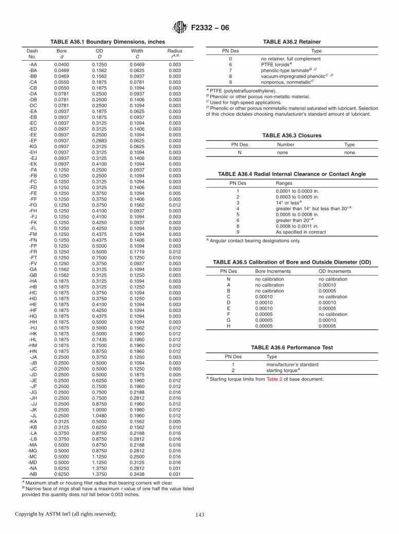
TABLE A36.1 Boundary Dimensions, inches
DashNo.
Bored
ODD
WidthC
RadiusrA,B
-AA 0.0400 0.1250 0.0469 0.003-BA 0.0469 0.1562 0.0625 0.003-BB 0.0469 0.1562 0.0937 0.003-CA 0.0550 0.1875 0.0781 0.003-CB 0.0550 0.1875 0.1094 0.003-DA 0.0781 0.2500 0.0937 0.003-DB 0.0781 0.2500 0.1406 0.003-DC 0.0781 0.2500 0.1094 0.003-EA 0.0937 0.1875 0.0625 0.003-EB 0.0937 0.1875 0.0937 0.003-EC 0.0937 0.3125 0.1094 0.003-ED 0.0937 0.3125 0.1406 0.003-EE 0.0937 0.2500 0.1094 0.003-EF 0.0937 0.2883 0.0625 0.003-KG 0.0937 0.3125 0.0625 0.003-EH 0.0937 0.3125 0.1094 0.003-EJ 0.0937 0.3125 0.1406 0.003-EK 0.0937 0.4100 0.1094 0.003-FA 0.1250 0.2500 0.0937 0.003-FB 0.1250 0.2500 0.1094 0.003-FC 0.1250 0.3125 0.1094 0.003-FD 0.1250 0.3125 0.1406 0.003-FE 0.1250 0.3750 0.1094 0.005-FF 0.1250 0.3750 0.1406 0.005-FG 0.1250 0.3750 0.1562 0.012-FH 0.1250 0.4100 0.0937 0.003-FJ 0.1250 0.4100 0.1094 0.003-FK 0.1250 0.4250 0.0937 0.003-FL 0.1250 0.4250 0.1094 0.003-FM 0.1250 0.4375 0.1094 0.003-FN 0.1250 0.4375 0.1406 0.003-FP 0.1250 0.5000 0.1094 0.003-FR 0.1250 0.5000 0.1719 0.012-FT 0.1250 0.7500 0.1250 0.010-FV 0.1250 0.3750 0.0937 0.003-GA 0.1562 0.3125 0.1094 0.003-GB 0.1562 0.3125 0.1250 0.003-HA 0.1875 0.3125 0.1094 0.003-HB 0.1875 0.3125 0.1250 0.003-HC 0.1875 0.3750 0.1094 0.003-HD 0.1875 0.3750 0.1250 0.003-HE 0.1875 0.4100 0.1094 0.003-HF 0.1875 0.4250 0.1094 0.003-HG 0.1875 0.4375 0.1094 0.003-HH 0.1875 0.5000 0.1094 0.003-HJ 0.1875 0.5000 0.1562 0.012-HK 0.1875 0.5000 0.1960 0.012-HL 0.1875 0.7435 0.1960 0.012-HM 0.1875 0.7500 0.1960 0.012-HN 0.1875 0.8750 0.1960 0.012-JA 0.2500 0.3750 0.1250 0.003-JB 0.2500 0.5000 0.1094 0.003-JC 0.2500 0.5000 0.1250 0.005-JD 0.2500 0.5000 0.1875 0.005-JE 0.2500 0.6250 0.1960 0.012-JF 0.2500 0.7500 0.1960 0.012-JG 0.2500 0.7500 0.2188 0.016-JH 0.2500 0.7500 0.2812 0.016-JJ 0.2500 0.8750 0.1960 0.012-JK 0.2500 1.0000 0.1960 0.012-JL 0.2500 1.0480 0.1960 0.012-KA 0.3125 0.5000 0.1562 0.005-KB 0.3125 0.6250 0.1562 0.010-LA 0.3750 0.8750 0.2188 0.016-LB 0.3750 0.8750 0.2812 0.016-MA 0.5000 0.8750 0.2188 0.016-MG 0.5000 0.8750 0.2812 0.016-MC 0.5000 1.1250 0.2500 0.016-MD 0.5000 1.1250 0.3125 0.016-NA 0.6250 1.3750 0.2812 0.031-NB 0.6250 1.3750 0.3438 0.031
A Maximum shaft or housing fillet radius that bearing corners will clear.B Narrow face of rings shall have a maximum r value of one half the value listedprovided this quantity does not fall below 0.003 inches.
TABLE A36.2 Retainer
PN Des Type
0 no retainer, full complement6 PTFE toroidsA
7 phenolic-type laminateB ,C
8 vacuum-impregnated phenolicC ,D
9 nonporous, nonmetallicC
A PTFE (polytetrafluoroethylene).B Phenolic or other porous non-metallic material.C Used for high-speed applications.D Phenolic or other porous nonmetallic material saturated with lubricant. Selectionof this choice dictates choosing manufacturer’s standard amount of lubricant.
TABLE A36.3 Closures
PN Des Number Type
N none none
TABLE A36.4 Radial Internal Clearance or Contact Angle
PN Des Ranges
1 0.0001 to 0.0003 in.2 0.0003 to 0.0005 in.3 14° or lessA
4 greater than 14° but less than 20°A
5 0.0005 to 0.0008 in.6 greater than 20°A
8 0.0008 to 0.0011 in.9 As specified in contract
A Angular contact bearing designations only.
TABLE A36.5 Calibration of Bore and Outside Diameter (OD)
PN Des Bore Increments OD Increments
N no calibration no calibrationA no calibration 0.00010B no calibration 0.00005C 0.00010 no calibrationD 0.00010 0.00010E 0.00010 0.00005F 0.00005 no calibrationG 0.00005 0.00010H 0.00005 0.00005
TABLE A36.6 Performance Test
PN Des Type
1 manufacturer’s standard2 starting torqueA
A Starting torque limits from Table 2 of base document.
F2332 − 06
143Copyright by ASTM Int'l (all rights reserved);

TABLE A36.7 Lubricant
PN Des Specification
P preservativeA
A MIL-PRF-6085B MIL-PRF-6085B
C DOD-L-81846D DOD-L-81846B
E MIL-PRF-23827F MIL-PRF-81322G MIL-G-81937H MIL-PRF-83261J MIL-S-81087C
K MIL-S-81087C
L MIL-DTL-53131, Grade 4M MIL-DTL-53131, Grade 6N MIL-DTL-53131, Grade 9Q MIL-DTL-53131, Grade 14R MIL-DTL-53131, Grade 40S As specified in contract
A PN Des “P” shall be used only with PN Des “P” in Table A36.8.B With barrier coat.C Canceled – lube no longer manufactured.
TABLE A36.8 Lubricant Amount
PN Des Quantity
P preservative amount as required byMIL-DTL-197
1 manufacturer’s standardA
2 oil per Table 5 of base document3 15 % grease4 25 % grease5 35 % grease6 45 % grease7 As specified in contract
A Grease: fill to minimum 25 %, maximum 40 % of bearing void. Oil: immerse andthen allow excess to drip off. The standard quantity of oil varies with each bearingsize.
F2332 − 06
144Copyright by ASTM Int'l (all rights reserved);
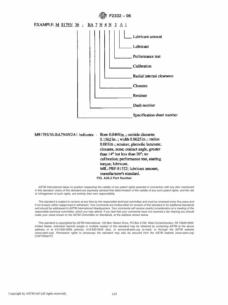
ASTM International takes no position respecting the validity of any patent rights asserted in connection with any item mentionedin this standard. Users of this standard are expressly advised that determination of the validity of any such patent rights, and the riskof infringement of such rights, are entirely their own responsibility.
This standard is subject to revision at any time by the responsible technical committee and must be reviewed every five years andif not revised, either reapproved or withdrawn. Your comments are invited either for revision of this standard or for additional standardsand should be addressed to ASTM International Headquarters. Your comments will receive careful consideration at a meeting of theresponsible technical committee, which you may attend. If you feel that your comments have not received a fair hearing you shouldmake your views known to the ASTM Committee on Standards, at the address shown below.
This standard is copyrighted by ASTM International, 100 Barr Harbor Drive, PO Box C700, West Conshohocken, PA 19428-2959,United States. Individual reprints (single or multiple copies) of this standard may be obtained by contacting ASTM at the aboveaddress or at 610-832-9585 (phone), 610-832-9555 (fax), or [email protected] (e-mail); or through the ASTM website(www.astm.org). Permission rights to photocopy the standard may also be secured from the ASTM website (www.astm.org/COPYRIGHT/).
FIG. A36.2 Part Number
F2332 − 06
145Copyright by ASTM Int'l (all rights reserved);