msg swing gate datasheet
DESCRIPTION
A market leader for more than 30 years and designed for high end commercial and industrial applicationsTRANSCRIPT
Vehicle Access - Swing Gates
MSG Swing Gate
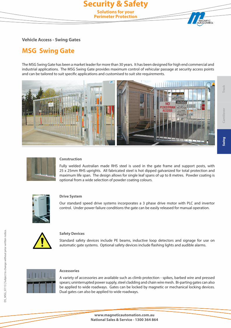
The MSG Swing Gate has been a market leader for more than 30 years. It has been designed for high end commercial and industrial applications. The MSG Swing Gate provides maximum control of vehicular passage at security access points and can be tailored to suit specific applications and customised to suit site requirements.
Safety Devices
Standard safety devices include PE beams, inductive loop detectors and signage for use on automatic gate systems. Optional safety devices include flashing lights and audible alarms.
Drive System
Our standard speed drive systems incorporates a 3 phase drive motor with PLC and invertor control. Under power failure conditions the gate can be easily released for manual operation.
Construction
Fully welded Australian made RHS steel is used in the gate frame and support posts, with 25 x 25mm RHS uprights. All fabricated steel is hot dipped galvanized for total protection and maximum life span. The design allows for single leaf spans of up to 8 metres. Powder coating is optional from a wide selection of powder coating colours.
Accessories
A variety of accessories are available such as climb protection - spikes, barbed wire and pressed spears; uninterrupted power supply, steel cladding and chain wire mesh. Bi-parting gates can also be applied to wide roadways. Gates can be locked by magnetic or mechanical locking devices. Dual gates can also be applied to wide roadways.
Security & SafetySolutions for your
Perimeter Protection
DS_
MSG
_07/
13 |
Subj
ect t
o ch
ange
with
out p
rior w
ritte
n no
tice.
Swin
gCa
ntile
ver
Trac
k
www.magneticautomation.com.auNational Sales & Service - 1300 364 864
www.magneticautomation.com.au
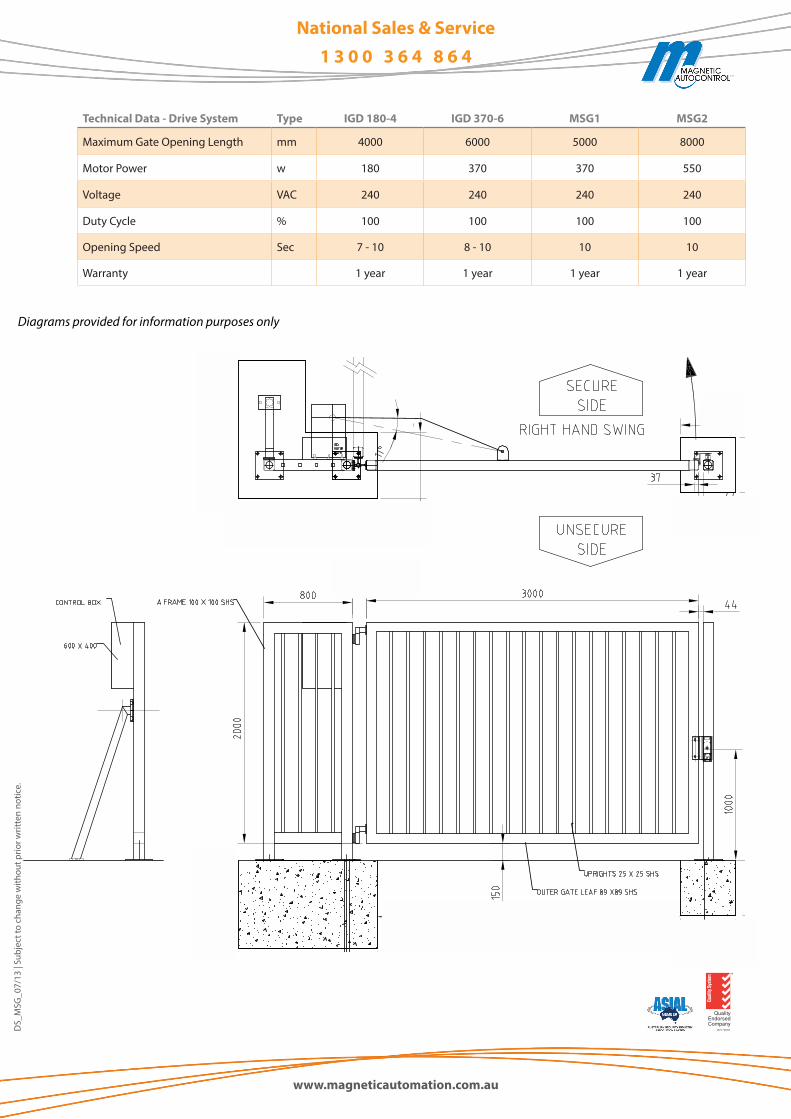
Technical Data - Drive System Type IGD 180-4 IGD 370-6 MSG1 MSG2
Maximum Gate Opening Length mm 4000 6000 5000 8000
Motor Power w 180 370 370 550
Voltage VAC 240 240 240 240
Duty Cycle % 100 100 100 100
Opening Speed Sec 7 - 10 8 - 10 10 10
Warranty 1 year 1 year 1 year 1 year
DS_
MSG
_07/
13 |
Subj
ect t
o ch
ange
with
out p
rior w
ritte
n no
tice.
National Sales & Service1 3 0 0 3 6 4 8 6 4
Diagrams provided for information purposes only