elite swing gate manual v3.01w
TRANSCRIPT

Elite®
INSTALLATION INSTRUCTIONS | OWNERS COPY
Swing Gate Opener
Technical Document
Installation Manual
v3.0114 Dec 2011
English
Part # 13295 (Manual)
2 Elite® - Swing Gate Opener Owner Installation Instructions
WARNING: It is vital for the safety of persons to follow all instructions. Failure to comply with the installation instructions and the safety warnings may result in serious personal injury and/or property and remote control opener damage. Please save these instructions for future reference.Automatic Technology Australia Pty Ltd to the extent that such may be lawfully excluded hereby expressly disclaims all conditions or warranties, statutory or otherwise which may be implied by laws as conditions or warranties of purchase of an Automatic Technology Australia Pty Ltd Elite® Swing Gate Opener. Automatic Technology Australia Pty Ltd hereby further expressly excludes all or any liability for any injury, damage, cost, expense or claim whatsoever suffered by any person as a result whether directly or indirectly from failure to install the Automatic Technology Australia Swing Gate Opener in accordance with these installation instructions.

Owner Installation Instructions Elite® - Swing Gate Opener 3
Elite®Swing Gate Opener
Important Safety Instructions 4
Features 6
Kit Contents 8
Drive Unit Installation 9
Installing Drive Unit Arms 11
Installing Minimum Sideroom Kit 12
Mounting Control Box 12
Five Wire Connection Single Leaf 14
Five Wire Connection Dual Leaf 15
Three Wire Connection Single Leaf 16
Three Wire Connection Dual Leaf 17
Control Board Layout 18
Menu Structure 20
Setting Travel Limits 21
Coding Transmitters 23
Standard Operating Modes 24
Control Board Adjustments 25
Menu 2 Current Trips 25
Menu 3 Auto-Close Times 26
Menu 4 Lock Times 27
Menu 5 Light Times 27
Menu 6 Motor Settings 27
Menu 7 Operating Modes 28
Diagnostic Tools 30
Menu 8.1 Test Inputs 30
Menu 8.2 Test Tx’ers 30
Menu 8.3 Display History 30
Menu 8.4 Memory Usage 30
Menu 8.5 Service Counter 31
Menu 8.6 Counters 31
Memory Tools 32
Menu 9.1 Clr Control 32
Menu 9.2 Clr Tx’ers 32
Setting Pedestrian Position 32
PE Beam installation 33
Accessories Installation 34
Battery Backup Installation 35
Troubleshooting Guide 36
Specifi cations 37
Spare Parts List 38
Warranty 40

4 Elite® - Swing Gate Opener Owner Installation Instructions
FOR ADDITIONAL SAFETY protection we strongly recommend the fi tting of a Photo Electric (PE) Beam. In most countries, PE Beams are mandatory on all gates fi tted with
automatic openers. For a small additional outlay, Automatic Technology recommends that Photo Electric Beams be installed with the automatic opener ensuring
additional safety and peace of mind.
DO NOT operate the gate opener unless the gate is in full view and free from objects such as cars and children/people. Make sure that the gate has fi nished moving before entering or leaving the driveway.
DO NOT operate the gate opener when children/people are near the gate. Children must be supervised near the gate at all times when the gate opener is in use. Serious personal injury and/or property damage can result from failure to follow this warning.
DO NOT allow children to operate the swing gate opener. Serious personal injury and/or property damage can result from failure to follow this warning.
Make sure that the Safety Obstruction Force system is working correctly, and is tested every month. Test as per the Installation Instructions Manual. Adjust if necessary and recheck. Failure to follow this rule could result in serious personal injury and/or property damage. This test must be repeated at regular intervals and the necessary adjustments made as required.
DO NOT disengage the swing gate opener to manual operation with children/people or any other objects including motor vehicles within the gateway.
If using a key switch, keypad or any device that can operate the swing gate opener, make sure it is out of reach of children and that the gateway is in full view at all times.
If the power supply cord is damaged, it must be replaced by an Automatic Technology service agent or suitably qualifi ed person.
Make sure that remote transmitters are kept out of reach of children.
WARNING: It is vital for the safety of persons to follow all instructions. Failure to comply with the following Safety Instructions may result in serious personal injury and/or property damage.
Important Safety Instructions

Owner Installation Instructions Elite® - Swing Gate Opener 5
The Elite® swing gate opener should not be immersed in water or sprayed directly by a hose or other water carrying device.
The gate(s) must be well balanced and in good working order. Faulty gates must be repaired by a qualifi ed technician prior to opener installation.
Remove or disengage all gate locks and mechanisms prior to installation of the opener.
Connect the gate opener to a properly earthed general purpose 240V mains power outlet installed by a qualifi ed electrical contractor.
Disconnect the power cord from mains power before making any repairs or removing covers. Only experienced service personnel should remove covers from the gate opener.
Keep hands and loose clothing clear of the gate and opener at all times.
When using Auto-Close mode, a Photo Electric Beam must be fi tted correctly and tested for operation at regular intervals. Extreme caution is recommended when
using Auto-Close mode. All safety instructions above must be followed.
In order for the gate opener to sense an object obstructing the gateway, some force must be exerted on the object. As a result the object, gate
and/or person may suffer damage or injury.
Make sure that the gate is fully open before driving into or out of the driveway. Make sure the gate is fully closed before leaving the
driveway.
The gate opener is not intended for use by young children or infi rm persons without adequate supervision. Children should
be supervised to ensure that they do not play with the remote transmitters or the opener.
Frequently examine the installation and mountings for signs of wear, damage or imbalance. DO NOT use if
repair or adjustment is needed since a fault in the installation or an incorrectly balanced gate may
cause injury.
Important Safety Instructions
Please read this instruction manual fully before attempting to install or use the opener. Failure to comply with the installation instructions may result in serious injury and/or property damage.

6 Elite® - Swing Gate Opener Owner Installation Instructions
Dual Leaf GateA dual leaf gate can be controlled with the addition of a second drive unit. Mains power is only required for the control box and a 5-core low voltage cable for the drive units.
OperationTo activate the gate simply press a button on the TrioCode® transmitter, keypad or other optional control devices. During an open or close cycle, the gate can be stopped by pressing the button whilst it is in motion. The next actuation will move the gate in the opposite direction.
Operator ConsoleThe DCB-05 gate controller features a LCD display operator console which simplifi es installation, adjustments and status indication. Features include editing transmitter storage and names, setting parameters, selecting specialised operating modes and performing system diagnostics.
TrioCode™ Code Hopping TechnologyEvery time a TrioCode™ transmitter is used, a new security code is randomly generated from over 4.29 billion possibilities. This greatly enhances the security of the system and makes “code grabbing” a thing of the past.
These transmitters also overcome interference issues by simultaneously sending a signal over three different frequencies. Even if two of the three signals are jammed, the system will still work.
Security Code StoreThe Elite® Swing Gate Opener uses revolutionary technology to securely store up to fi ve hundred and eleven (511) transmitters in its memory with the ability to assign an 11 character name to each.
InstallationThe display console on the DCB-05 gate controller “holds your hand” through the installation and setup process. Also, during installation a handheld transmitter can be used to set gate travel limits, allowing the installer to closely monitor the gate’s position and stop points instead of having to be within arms reach of the console.
Gate Sync DelayIf the gate leafs overlap, a delay can be used to start one leaf moving without interfering with the other.
Features
Thank you for purchasing the Elite® Swing Gate Opener from Automatic Technology. Designed for residential hinged swing gates by our world renowned team of engineers, this unit will give years of smart, simple and secure operation. Listed below are some of its many features.
Owner Installation Instructions Elite® - Swing Gate Opener 7
ISS (Intelligent Safety System)Should the gate hit an obstacle or be restricted in some manner, it will automatically reverse. The
amount of force the gate should encounter before reversing is automatically adjusted by the control system during the initialisation of the automatic opener. The gate will also stop if
restricted whilst opening. The Safety Obstruction Force should be checked at least once a month. See installation manual for instructions.
Status IndicatorThe LCD console display screen indicates through text the status of the Elite®
Swing Gate Opener. When the MAIN SCREEN is displayed, the current position of the gate or the result of the last movement can be viewed. The display also shows the countdown timer for Auto-Close operations. Any active input will also be displayed along with the state of various features such as periodic service, battery backup operation and vacation mode.
Control of Lock and LightsThe incorporated controller has dedicated outputs for operating an electric lock, warning or courtesy lights. The timing of these outputs can be adjusted to suit your needs. In addition, a button on a remote transmitter can be coded to operate the light output.
Extensive Operating Modes Via Control Inputs The DCB-05 gate controller can be confi gured to operate in many
different ways via the seven (7) control and safety inputs which include P.E, AUXILIARY OPEN, STOP, CLOSE, OSC, SWIPE and PEDESTRIAN.
Operating Modes Via Remote ControlsOperation is provided with each transmitter’s button being able to be confi gured
to operate one of OSC, PEDESTRIAN, SWIPE, CLOSE, OPEN, STOP, LIGHT or VACATION functions.
The functionality of the transmitter is further enhanced by four (4) Auto-Close modes, three (3) PE Beam response modes and two (2) pedestrian response modes.
SmartSolar™ and Battery Backup Compatibility (optional)The Elite® swing gate opener can be fi tted with a SmartSolar™ or Battery Backup kit for operation in the event of a power outage, or where mains power access is not available.
Pedestrian ModeThe gate can be programmed to open partially to allow pedestrian access. In a dual leaf gate, only one leaf opens to allow pedestrians through without permitting vehicle access.
Manual Operation The opener can be disengaged and the gate operated manually by opening the drive unit cover and disengaging the gearbox. If power to the opener is disrupted for any reason, it can be disengaged. This will allow you to manually open or close the gate.

8 Elite® - Swing Gate Opener Owner Installation Instructions
Kit Contents
01
02
03
04
09
07
05
ITEM DESCRIPTION QTY 1. Drive Unit 1 2. Drive Arm Extension 1 3. Slave Arm 1 4. Gate Mounting Bracket 1 5. Plastic Washer 4 6. Shoulder Screw 2 7. Hex Head Screw 2 8. Spring Washer 2 9. Flat Washer 210. Control Box 111. Control Box Mounting Bracket 412. PTX-5 Keyring Transmitter 2
08
06
10
11
12
01fi g

Owner Installation Instructions Elite® - Swing Gate Opener 9
Drive Unit Installation
Mounting The Drive UnitThe Elite® swing gate opener is designed to operate most residential swing gates. The gates must be in good working condition and should operate by hand relatively freely. Wind loading may affect the operation of the opener in high wind areas. Correct obstruction and reversing settings should be chosen for trouble free operation.
Pre-installation InspectionBefore commencing installation, check the following:
The gate moves freely by hand for the full length of open and close travel.The pier or post for mounting must be of solid construction (Brick, solid timber or steel). It must bear most of the force applied by the drive unit.A weatherproof 240V 10A general purpose power point should be available within one metre of the pier/post. If Elite® gate openers are required, provision for underground cabling should be made from one post to the other.
1.
2.
3.
02fi g
Gate in open position
Ensure sideroom clearance is adequate. Refer to Table on page 10. If there is not enough sideroom available, the Minimum Sideroom Kit (Page 12) is required.The mount distance of the Drive Unit should be recorded. This value will be used later.
4.
5.
Mountdistance
Sideroom clearance
Hingedistance
Wall/PierFence

10 Elite® - Swing Gate Opener Owner Installation Instructions
04fi g
05fi g
Drive Unit Installation
Mount Distance Hinge Distance
0 50 100 125 150 180 200 220 mm
Sideroom clearance
90 470 470 470 470 470 470 465 460 mm
120 450 470 480 470 465 460 435 425 mm
140 470 465 470 465 460 440 420 390 mm
200 470 465 445 430 400 350 390 250 mm
The mount distance for the drive unit and the hinge distance for the gate can be selected to optimise the sideroom clearance. See Fig. 03.
NOTE: If the gate is already installed, measure the hinge distance and use this table to optimise the mount distance.
Mount drive unit using four (4) 10mm loxins or dynabolts. Make sure that the Drive Unit is mounted at an appropriate height from the ground - allow minimum 35mm clearance for drive arm extension.
NOTE: If the gateway slopes away from pier/post, make sure an allowance is made for clearance of the drive arm extension and slave arm to not touch the ground.
Manual OperationDisengage drive motor by pulling manual release pin up using the release ring. While holding the ring, rotate the motor assembly clockwise. (Fig. 04, 05 & 06)
To re-engage, pull pin and rotate motor assembly anti-clockwise until manual release pin clicks into place.
1.
2.
Engagedposition
Disengagedposition
06fi g
03fi g
Owner Installation Instructions Elite® - Swing Gate Opener 11
Installing Drive Unit Arms
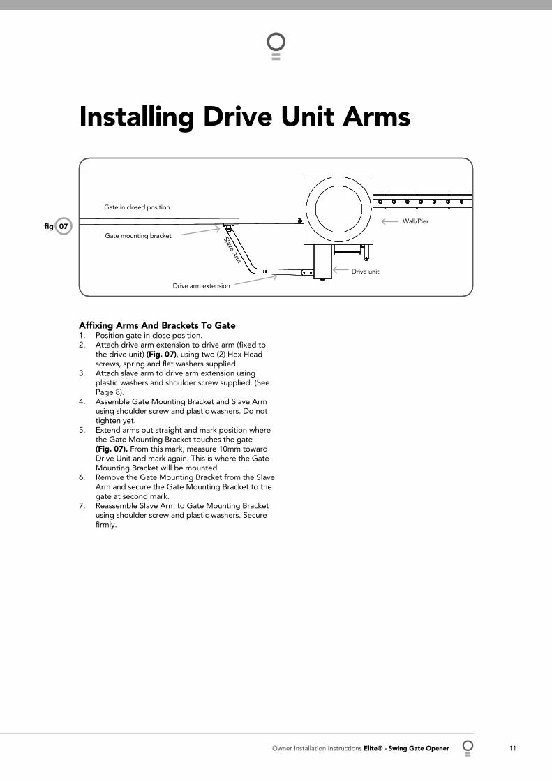
07fi g
Gate in closed position
Drive unit
Wall/Pier
Slave Arm
Affi xing Arms And Brackets To GatePosition gate in close position.Attach drive arm extension to drive arm (fi xed to the drive unit) (Fig. 07), using two (2) Hex Head screws, spring and fl at washers supplied.Attach slave arm to drive arm extension using plastic washers and shoulder screw supplied. (See Page 8).Assemble Gate Mounting Bracket and Slave Arm using shoulder screw and plastic washers. Do not tighten yet.Extend arms out straight and mark position where the Gate Mounting Bracket touches the gate (Fig. 07). From this mark, measure 10mm toward Drive Unit and mark again. This is where the Gate Mounting Bracket will be mounted.Remove the Gate Mounting Bracket from the Slave Arm and secure the Gate Mounting Bracket to the gate at second mark. Reassemble Slave Arm to Gate Mounting Bracket using shoulder screw and plastic washers. Secure fi rmly.
1.2.
3.
4.
5.
6.
7.
Drive arm extension
Gate mounting bracket

12 Elite® - Swing Gate Opener Owner Installation Instructions
Mounting Control Box
Installing Minimum Sideroom KitMinimum Sideroom KitIf you have limited sideroom, an optional minimum sideroom kit reduces the gate opener’s required sideroom to the width of the drive unit (135mm). (ATA Order code 90182).
Fitting Minimum Sideroom KitSecure the extension arm from the Minimum Sideroom Kit onto drive arm extension with supplied M12 screws.Drill Ø12 hole in the Drive Arm Extension (use hole in extension arm as a guide). Insert the other M12 screw and secure with spring washer and nut. Check that the screws are tight (Fig. 09)Check that the Drive Unit is disengaged and the gate is closed. Slide the Guide Track over the idler. Locate Track on the gate and check travel of the Arm. The idler should always be inside the Guide Track in the closed and open positions (Fig. 08).Secure the track to the gate (weld if possible).
NOTE: If a shorter arm is required, drill the drive arm extension and extension arm where appropriate. You should not have to cut the arms and you should still be able to use pre-threaded hole in the drive arm extension.
1.
2.
3.
4.
5.
110
175
55
275
Mounting Control Box
CAUTION: do not use any cables which carry green/yellow wires as this signifi es earth, and do not comply with electrical authority regulations.
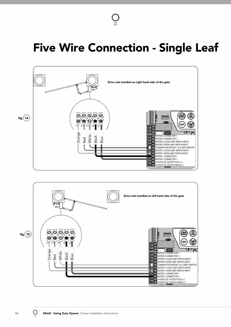
The control box should be mounted near the drive unit using four (4) 6mm screws. Drill holes as per (Fig. 10). When locating the control box, allow ample space around the unit for easy access and wiring connections. Remove cover from control box. Determine which leaf you would like to open fi rst and close last. This gate leaf must be connected to Motor 1 (M1) terminals on the control board.Connect drive unit(s) to control board using 5-core or 3-core cable.Two diodes IN4001 per drive unit must be used with 3-core cable instalation. For detailed electrical connection see (Fig. 14 -21).
1.
2.
3.4.
5.
Socket head screw M12 x 60
Idler
Nylock nut M12
Slave arm
Drive arm extension
Drill 12.5 mm
Shoulder screw
Control box mounting
Drive unit mounting
08fi g
09fi g
10fi g
Owner Installation Instructions Elite® - Swing Gate Opener 13
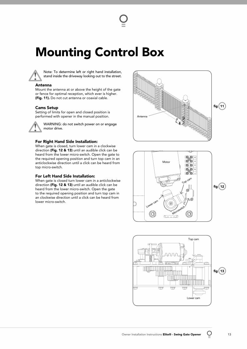
Note: To determine left or right hand installation, stand inside the driveway looking out to the street.
AntennaMount the antenna at or above the height of the gate or fence for optimal reception, which ever is higher. (Fig. 11). Do not cut antenna or coaxial cable.
Cams SetupSetting of limits for open and closed position is performed with opener in the manual position.
WARNING: do not switch power on or engage motor drive.
For Right Hand Side Installation:When gate is closed, turn lower cam in a clockwise direction (Fig. 12 & 13) until an audible click can be heard from the lower micro-switch. Open the gate to the required opening position and turn top cam in an anticlockwise direction until a click can be heard from top micro-switch.
For Left Hand Side Installation:When gate is closed turn lower cam in a anticlockwise direction (Fig. 12 & 13) until an audible click can be heard from the lower micro-switch. Open the gate to the required opening position and turn top cam in an clockwise direction until a click can be heard from lower micro-switch.
Mounting Control Box
Top cam
Lower cam
Motor
Microswitch
11fi g
12fi g
13fi g
Antenna
Top cam
Lower cam
14 Elite® - Swing Gate Opener Owner Installation Instructions
Five Wire Connection - Single Leaf
MOTOR 2 CONNECTOR 1MOTOR 2 CONNECTOR 2MOTOR 2 CLOSE LIMIT SWITCH INPUTMOTOR 2 OPEN LIMIT SWITCH INPUTCOMMON FOR MOTOR 1 & 2 LIMIT SWITCHS MOTOR 1 CLOSE LIMIT SWITCH INPUTMOTOR 1 OPEN LIMIT SWITCH INPUTMOTOR 1 CONNECTOR 1MOTOR 1 CONNECTOR 224 VOLTS DC OUTPUT PLUS (+)24 VOLTS DC OUTPUT MINUS (-)
MOTOR 2 CONNECTOR 1MOTOR 2 CONNECTOR 2MOTOR 2 CLOSE LIMIT SWITCH INPUTMOTOR 2 OPEN LIMIT SWITCH INPUTCOMMON FOR MOTOR 1 & 2 LIMIT SWITCHS MOTOR 1 CLOSE LIMIT SWITCH INPUTMOTOR 1 OPEN LIMIT SWITCH INPUTMOTOR 1 CONNECTOR 1MOTOR 1 CONNECTOR 224 VOLTS DC OUTPUT PLUS (+)24 VOLTS DC OUTPUT MINUS (-)
Ora
nge
Red
Whi
te
Bla
ck
Blu
e
Ora
nge
Red
Whi
te
Bla
ck
Blu
e
14fi g
15fi g
Drive unit installed on right hand side of the gate
Drive unit installed on left hand side of the gate
M1
M1

Owner Installation Instructions Elite® - Swing Gate Opener 15
M2
MOTOR 2 CONNECTOR 1MOTOR 2 CONNECTOR 2MOTOR 2 CLOSE LIMIT SWITCH INPUTMOTOR 2 OPEN LIMIT SWITCH INPUTCOMMON FOR MOTOR 1 & 2 LIMIT SWITCHS MOTOR 1 CLOSE LIMIT SWITCH INPUTMOTOR 1 OPEN LIMIT SWITCH INPUTMOTOR 1 CONNECTOR 1MOTOR 1 CONNECTOR 224 VOLTS DC OUTPUT PLUS (+)24 VOLTS DC OUTPUT MINUS (-)
MOTOR 2 CONNECTOR 1MOTOR 2 CONNECTOR 2MOTOR 2 CLOSE LIMIT SWITCH INPUTMOTOR 2 OPEN LIMIT SWITCH INPUTCOMMON FOR MOTOR 1 & 2 LIMIT SWITCHS MOTOR 1 CLOSE LIMIT SWITCH INPUTMOTOR 1 OPEN LIMIT SWITCH INPUTMOTOR 1 CONNECTOR 1MOTOR 1 CONNECTOR 224 VOLTS DC OUTPUT PLUS (+)24 VOLTS DC OUTPUT MINUS (-)
M1
M1M2
Ora
nge
Red
Whi
te
Bla
ck
Blu
e
Ora
nge
Red
Whi
te
Bla
ck
Blu
e
Ora
nge
Red
Whi
te
Bla
ck
Blu
e
Ora
nge
Red
Whi
te
Bla
ck
Blu
e
16fi g
17fi g
Left hand leaf opens fi rst and close last
Right hand leaf opens fi rst and close last
Five Wire Connection - Dual Leaf

16 Elite® - Swing Gate Opener Owner Installation Instructions
Three Wire Connection - Single Leaf
MOTOR 2 CONNECTOR 1MOTOR 2 CONNECTOR 2MOTOR 2 CLOSE LIMIT SWITCH INPUTMOTOR 2 OPEN LIMIT SWITCH INPUTCOMMON FOR MOTOR 1 & 2 LIMIT SWITCHS MOTOR 1 CLOSE LIMIT SWITCH INPUTMOTOR 1 OPEN LIMIT SWITCH INPUTMOTOR 1 CONNECTOR 1MOTOR 1 CONNECTOR 224 VOLTS DC OUTPUT PLUS (+)24 VOLTS DC OUTPUT MINUS (-)
MOTOR 2 CONNECTOR 1MOTOR 2 CONNECTOR 2MOTOR 2 CLOSE LIMIT SWITCH INPUTMOTOR 2 OPEN LIMIT SWITCH INPUTCOMMON FOR MOTOR 1 & 2 LIMIT SWITCHS MOTOR 1 CLOSE LIMIT SWITCH INPUTMOTOR 1 OPEN LIMIT SWITCH INPUTMOTOR 1 CONNECTOR 1MOTOR 1 CONNECTOR 224 VOLTS DC OUTPUT PLUS (+)24 VOLTS DC OUTPUT MINUS (-)
Whi
te
BlackBlue
18fi g
19fi g
M1
M1
WhiteBlue
Black
Drive unit installed on right hand side of the gate.
One diode IN4001 is connected between1 and 4. The second diode IN4001 is connected between 2 and 5 on the drive unit terminal.
Drive unit installed on right hand side of the gate .
One diode IN4001 is connected between1 and 4. The second diode IN4001 is connected between 2 and 5 on the drive unit terminal.
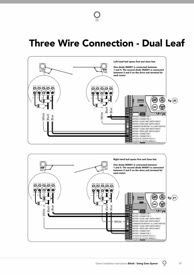
Owner Installation Instructions Elite® - Swing Gate Opener 17
M2
MOTOR 2 CONNECTOR 1MOTOR 2 CONNECTOR 2MOTOR 2 CLOSE LIMIT SWITCH INPUTMOTOR 2 OPEN LIMIT SWITCH INPUTCOMMON FOR MOTOR 1 & 2 LIMIT SWITCHS MOTOR 1 CLOSE LIMIT SWITCH INPUTMOTOR 1 OPEN LIMIT SWITCH INPUTMOTOR 1 CONNECTOR 1MOTOR 1 CONNECTOR 224 VOLTS DC OUTPUT PLUS (+)24 VOLTS DC OUTPUT MINUS (-)
MOTOR 2 CONNECTOR 1MOTOR 2 CONNECTOR 2MOTOR 2 CLOSE LIMIT SWITCH INPUTMOTOR 2 OPEN LIMIT SWITCH INPUTCOMMON FOR MOTOR 1 & 2 LIMIT SWITCHS MOTOR 1 CLOSE LIMIT SWITCH INPUTMOTOR 1 OPEN LIMIT SWITCH INPUTMOTOR 1 CONNECTOR 1MOTOR 1 CONNECTOR 224 VOLTS DC OUTPUT PLUS (+)24 VOLTS DC OUTPUT MINUS (-)
M1
M1M2
Whi
te
Bla
ck
Blu
e
Whi
te Bla
ck
Blu
e
Whi
te Bla
ck
Blu
e
White
Bla
ck
Blu
e
20fi g
21fi g
Right hand leaf opens fi rst and close last.
One diode IN4001 is connected between1 and 4. The second diode IN4001 is connected between 2 and 5 on the drive unit terminal for each motor.
Three Wire Connection - Dual Leaf
Left hand leaf opens fi rst and close last.
One diode IN4001 is connected between1 and 4. The second diode IN4001 is connected between 2 and 5 on the drive unit terminal for each motor.

18 Elite® - Swing Gate Opener Owner Installation Instructions
03
02
04
05
06
07
08
09
10
11
12
13
14
15
16
17
18
19
20
21
22
23
24
25
26
27
29
01 PE V+ is used to power photo electric beam.
PE In for photo electric beam for safety
PE (v-) is used to supply (-) volt to photo electric beam.
Aux control input
OPN Programmable N/O or N/C input terminal
STP Programmable N/O or N/C input terminal
CLS N/O input terminal
OSC N/O input terminal
SWP N/O input terminal
PED N/O input terminal
COM terminal for input terminals 1 to 8
OUTPUT 2 (optional relay module coil drive)
OUTPUT 2 (optional relay module coil drive)
OUTPUT 1 N/C relay contact
OUTPUT 1 COM relay contact
OUTPUT 1 N/O relay contact
MOTOR 2 terminal 1
MOTOR 2 terminal 2
MOTOR 2 close limit switch input terminal
MOTOR 2 open limit switch input terminal
COM terminal for Terminals 16,17,19 & 20.
MOTOR 1 close limit switch input terminal
MOTOR 1 open limit switch input terminal
MOTOR 1 terminal 1
MOTOR 1 terminal 2
24VDC (+) output for powering accessories
24VDC (-) output for powering accessories
Standby battery / solar charger connector
24VAC power input (from transformer)
10 amp fuse
Programmer Input
Console keypad
Console display (LCD)
Antenna connector
28
30
31
32
33
34
Control Board Layout
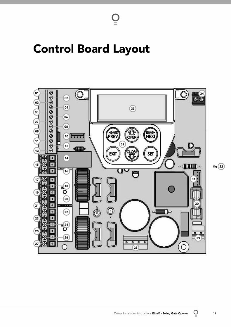
Owner Installation Instructions Elite® - Swing Gate Opener 19
Control Board Layout
01
02
22fi g
03
0405
06
07
08
09
10
11
12
13
14
15
17
19
21
23
25
27
16
18
20
22
24
26
28
29
30
31
32
33
34
20 Elite® - Swing Gate Opener Owner Installation Instructions
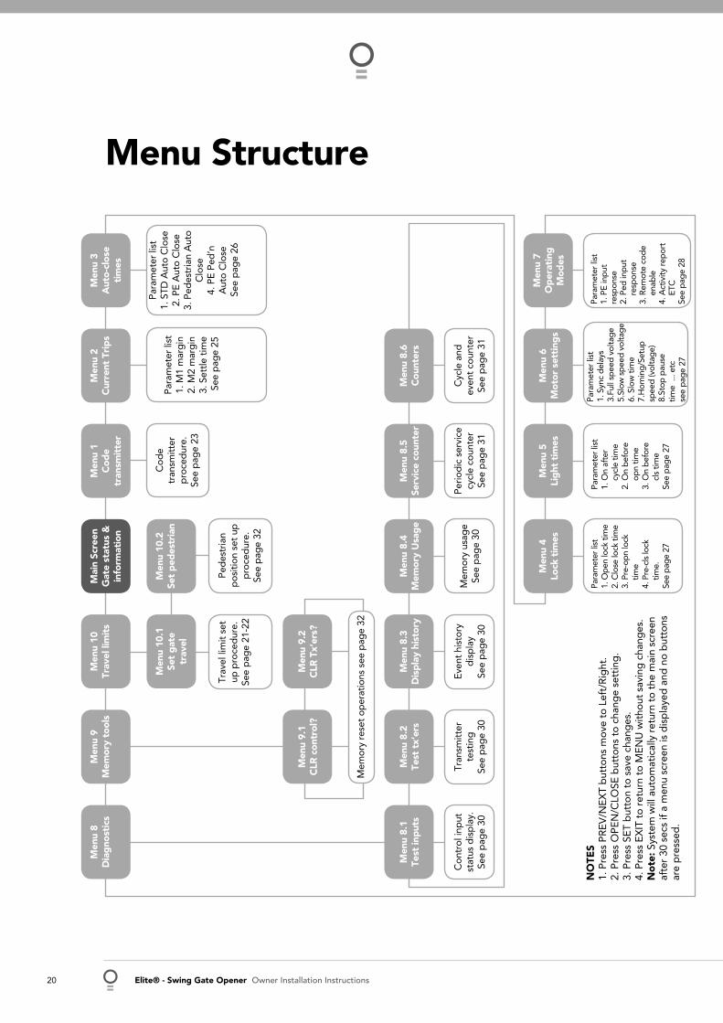
Menu Structure
Men
u 8
Dia
gno
stic
sM
enu
9M
emor
y to
ols
Men
u 10
Trav
el li
mit
sM
enu
1C
ode
tran
smit
ter
Men
u 2
Cur
rent
Tri
ps
Men
u 3
Aut
o-cl
ose
tim
es
Mai
n Sc
reen
Gat
e st
atus
&
info
rmat
ion
Men
u 10
.1Se
t g
ate
trav
el
Men
u 10
.2Se
t p
edes
tria
nC
ode
tran
smitt
er
pro
ced
ure.
Se
e p
age
23
Para
met
er li
st1.
M1
mar
gin
2. M
2 m
arg
in3.
Set
tle t
ime
See
pag
e 25
Para
met
er li
st1.
STD
Aut
o C
lose
2. P
E A
uto
Clo
se3.
Ped
estr
ian
Aut
o
Clo
se4.
PE
Ped
’n
Aut
o C
lose
See
pag
e 26
Trav
el li
mit
set
up p
roce
dur
e.
See
pag
e 21
-22
Ped
estr
ian
pos
ition
set
up
p
roce
dur
e.
See
pag
e 32
Men
u 9.
1C
LR c
ontr
ol?
Men
u 9.
2C
LR T
x’er
s?
Mem
ory
rese
t op
erat
ions
see
pag
e 32
Men
u 8.
1Te
st in
put
sM
enu
8.2
Test
tx’
ers
Men
u 8.
3D
isp
lay
hist
ory
Men
u 8.
5Se
rvic
e co
unte
rM
enu
8.6
Cou
nter
sM
enu
8.4
Mem
ory
Usa
ge
Con
trol
inp
ut
stat
us d
isp
lay.
Se
e p
age
30
Tran
smitt
er
test
ing
See
pag
e 30
Even
t hi
stor
y d
isp
lay
See
pag
e 30
Perio
dic
ser
vice
cy
cle
coun
ter
See
pag
e 31
Cyc
le a
nd
even
t co
unte
rSe
e p
age
31
Mem
ory
usag
eSe
e p
age
30
Para
met
er li
st
1. O
n af
ter
c
ycle
tim
e 2.
On
bef
ore
o
pn
time
3. O
n b
efor
e
cls
tim
e Se
e p
age
27
Para
met
er li
st
1. S
ync
del
ays
3.Fu
ll sp
eed
vol
tag
e5.
Slow
sp
eed
vol
tag
e6.
Slo
w t
ime
7.H
omin
g/S
etup
sp
eed
(vol
tag
e)8.
Stop
pau
setim
e ..
. etc
see
pag
e 27
Para
met
er li
st
1. P
E in
put
re
spon
se
2. P
ed in
put
r
esp
onse
3.
Rem
ote
cod
e
ena
ble
4.
Act
ivity
rep
ort
E
TC
See
pag
e 28
Para
met
er li
st
1. O
pen
lock
tim
e 2.
Clo
se lo
ck ti
me
3. P
re-o
pn lo
ck
tim
e 4.
Pre
-cls
lock
ti
me.
Se
e pa
ge 2
7
NO
TES
1. P
ress
PR
EV/N
EXT
but
tons
mov
e to
Lef
t/R
ight
.2.
Pre
ss O
PEN
/CLO
SE b
utto
ns t
o ch
ang
e se
ttin
g.
3. P
ress
SET
but
ton
to s
ave
chan
ges
.4.
Pre
ss E
XIT
to
retu
rn t
o M
ENU
with
out
savi
ng c
hang
es.
No
te: S
yste
m w
ill a
utom
atic
ally
ret
urn
to t
he m
ain
scre
enaf
ter
30 s
ecs
if a
men
u sc
reen
is d
isp
laye
d a
nd n
o b
utto
nsar
e p
ress
ed.
Men
u 5
Lig
ht t
imes
Men
u 6
Mot
or s
etti
ngs
Men
u 7
Op
erat
ing
M
odes
Men
u 4
Lock
tim
es
Owner Installation Instructions Elite® - Swing Gate Opener 21
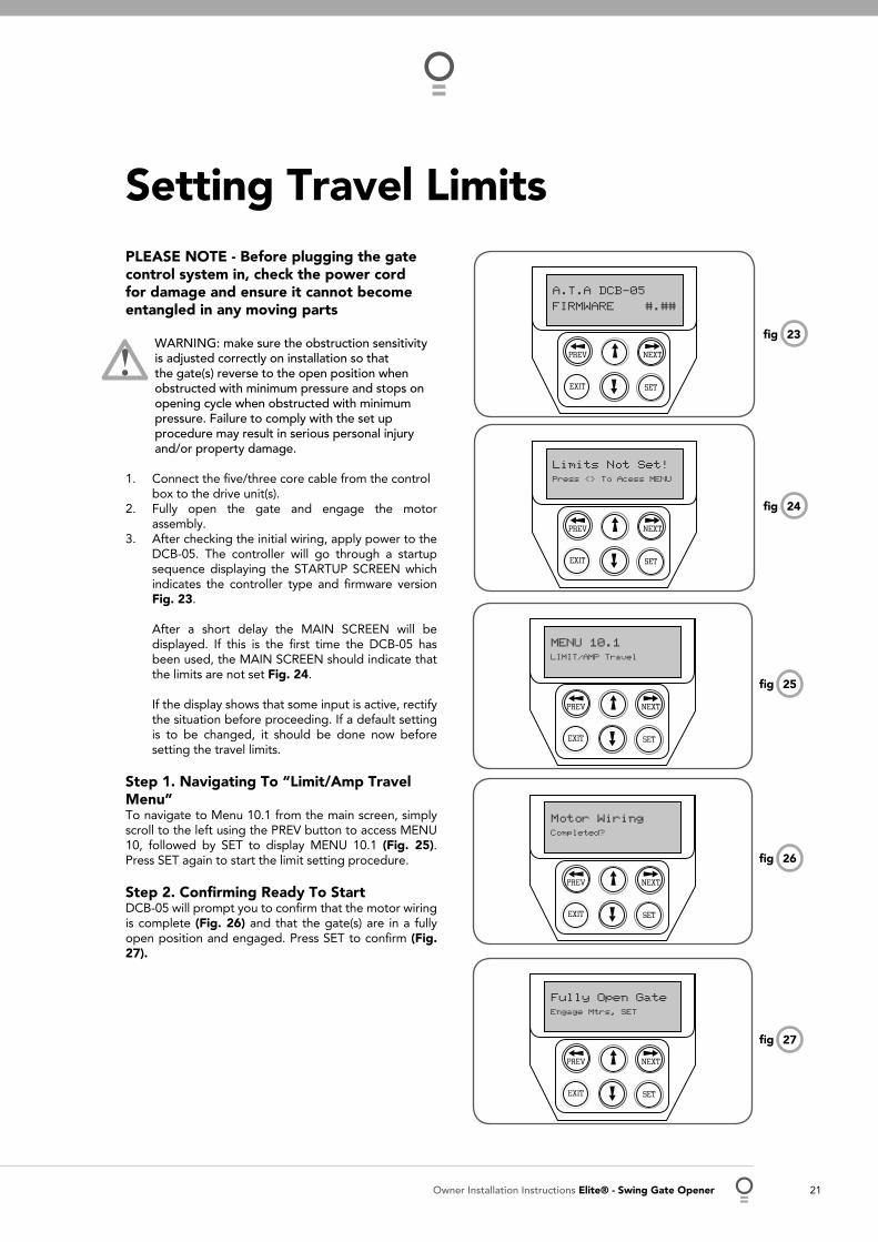
PLEASE NOTE - Before plugging the gate control system in, check the power cord for damage and ensure it cannot become entangled in any moving parts
WARNING: make sure the obstruction sensitivity is adjusted correctly on installation so that the gate(s) reverse to the open position when obstructed with minimum pressure and stops on opening cycle when obstructed with minimum pressure. Failure to comply with the set up procedure may result in serious personal injury and/or property damage.
Connect the fi ve/three core cable from the control box to the drive unit(s).Fully open the gate and engage the motor assembly.After checking the initial wiring, apply power to the DCB-05. The controller will go through a startup sequence displaying the STARTUP SCREEN which indicates the controller type and fi rmware version Fig. 23.
After a short delay the MAIN SCREEN will be displayed. If this is the fi rst time the DCB-05 has been used, the MAIN SCREEN should indicate that the limits are not set Fig. 24.
If the display shows that some input is active, rectify the situation before proceeding. If a default setting is to be changed, it should be done now before setting the travel limits.
Step 1. Navigating To “Limit/Amp Travel Menu”To navigate to Menu 10.1 from the main screen, simply scroll to the left using the PREV button to access MENU 10, followed by SET to display MENU 10.1 (Fig. 25). Press SET again to start the limit setting procedure.
Step 2. Confi rming Ready To StartDCB-05 will prompt you to confi rm that the motor wiring is complete (Fig. 26) and that the gate(s) are in a fully open position and engaged. Press SET to confi rm (Fig. 27).
1.
2.
3.
23fi g
24fi g
A.T.A DCB-05
FIRMWARE #.##
PREV NEXT
EXIT SET
Limits Not Set!Press <> To Acess MENU
PREV NEXT
EXIT SET
Setting Travel Limits
MENU 10.1LIMIT/AMP Travel
PREV NEXT
EXIT SET
Motor WiringCompleted?
PREV NEXT
EXIT SET
25fi g
26fi g
Fully Open GateEngage Mtrs, SET
PREV NEXT
EXIT SET
27fi g

22 Elite® - Swing Gate Opener Owner Installation Instructions
Step 3. Confi rming Correct Wiring DetectedDCB-05 will now automatically detect the type of drive unit used by the number of wires used. If the correct number of wires is displayed (Fig. 28) then press SET to continue. Otherwise press EXIT and check the wiring.
Step 4. Confi rming Motors DetectedDCB-05 will now automatically detect if one or two motor are connected. If the correct number is displayed, then press SET to confi rm. Otherwise press EXIT and check the wiring (Fig. 29).
Step 5. Adjusting Close Limit(s)DCB-05 will now prompt one at a time for the motor(s) to be driven to the desired close limit and for the limit switches to be adjusted so that the motor stops at the desired position (Fig. 30).
The motor can be driven using the UP and DOWN buttons on the console keypad or Button 1 and 4 of a transmitter. In the limits setup mode, the display will show the percentage of the power used to move the gate (Fig. 31).
After making adjustments to the limit switch positions always re-approach the limit at full speed by driving the motor open a short distance and then driving it close again. When the close limit has been adjusted, press SET to continue.
Note: If the motor drives in the wrong direction (UP closes gate / DOWN opens gate), the motor wires need to be swapped.
Step 6. Adjusting Open Limit(s)DCB-05 will now prompt for the motor(s) to be driven to the desired open limit and for the limit switches to be adjusted so that the motor stops at the desired position.
The motor can be driven using the UP and DOWN buttons on the console keypad or Button 1 and 4 of a transmitter. In the limits setup mode, the display will show the percentage of the power used to move the gate.
After making adjustments to the limit switch positions always re-approach the limit at full speed by driving the motor close a short distance and then driving it open again. When the open limit has been adjusted, press SET.
Step 7. Automatic Profi lingAfter a brief pause, DCB-05 will automatically close and open gate several times and learn the gates load and travel characteristics. When the setup is complete, the MAIN SCREEN will be displayed “Gate is closed”. The gate can now be used.
29fi g
28fi g
Motor=5 Wire
PREV NEXT
EXIT SET
Press Set If OK
PRESS
M1&2 Detected
PREV NEXT
EXIT SET
Press Set If OK
PRESS
30fi g
Confi rming Detected Motor Wiring
Confi rming Detected Motor Wiring
PREV NEXT
EXIT SET
Press SET
DRIVE M2 CLOSE
ORPRESS
PRESS
Adjusting The CLOSE LIMIT
31fi g
PREV NEXT
EXIT SET
10%
DRIVE M2 CLOSEPRESS
OR
PRESS
Setting Travel Limits (Cont.)
Owner Installation Instructions Elite® - Swing Gate Opener 23
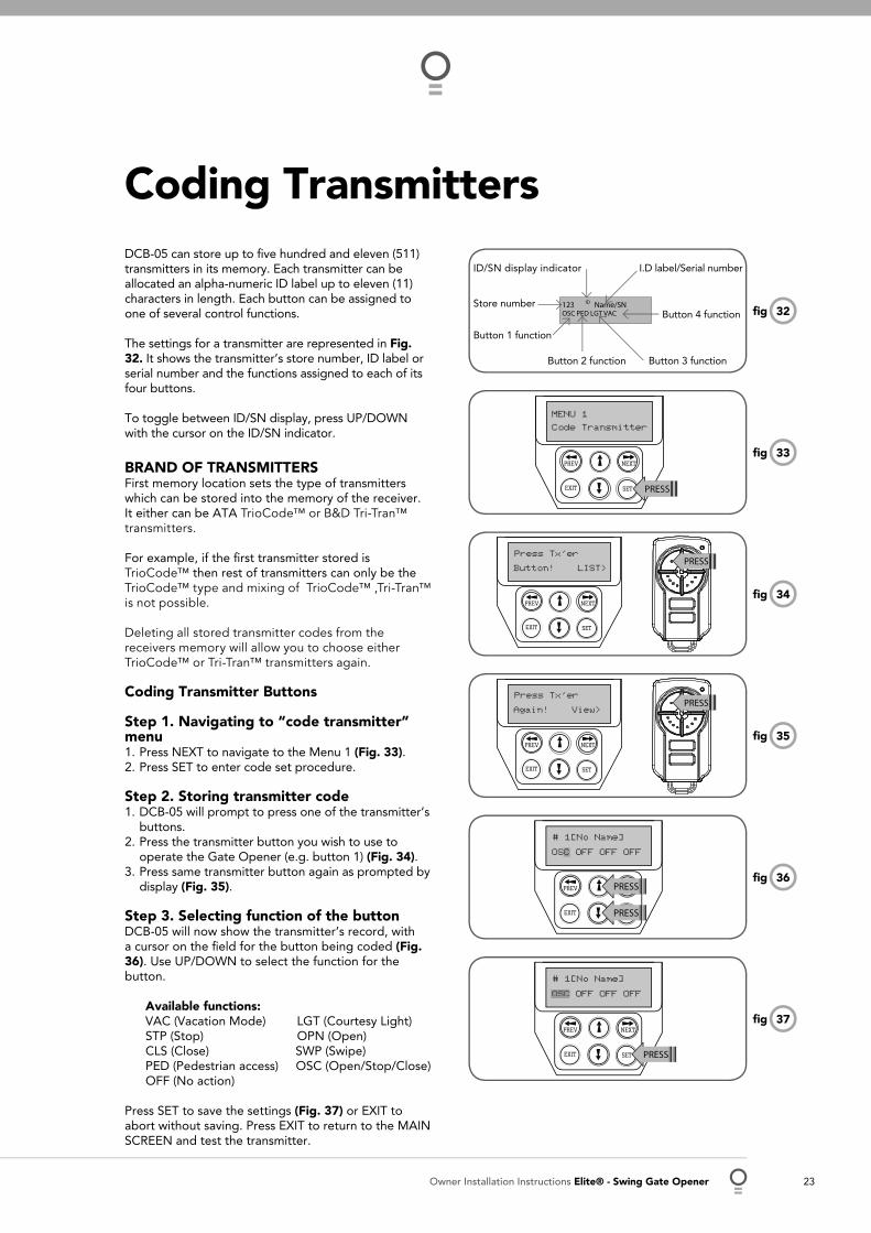
Coding Transmitters DCB-05 can store up to fi ve hundred and eleven (511) transmitters in its memory. Each transmitter can be allocated an alpha-numeric ID label up to eleven (11) characters in length. Each button can be assigned to one of several control functions.
The settings for a transmitter are represented in Fig. 32. It shows the transmitter’s store number, ID label or serial number and the functions assigned to each of its four buttons.
To toggle between ID/SN display, press UP/DOWN with the cursor on the ID/SN indicator.
BRAND OF TRANSMITTERSFirst memory location sets the type of transmitters which can be stored into the memory of the receiver. It either can be ATA TrioCode™ or B&D Tri-Tran™ transmitters.
For example, if the fi rst transmitter stored is TrioCode™ then rest of transmitters can only be the TrioCode™ type and mixing of TrioCode™ ,Tri-Tran™ is not possible.
Deleting all stored transmitter codes from the receivers memory will allow you to choose either TrioCode™ or Tri-Tran™ transmitters again.
Coding Transmitter Buttons
Step 1. Navigating to “code transmitter” menu
Press NEXT to navigate to the Menu 1 (Fig. 33). Press SET to enter code set procedure.
Step 2. Storing transmitter code DCB-05 will prompt to press one of the transmitter’s buttons. Press the transmitter button you wish to use to operate the Gate Opener (e.g. button 1) (Fig. 34). Press same transmitter button again as prompted by display (Fig. 35).
Step 3. Selecting function of the button DCB-05 will now show the transmitter’s record, with a cursor on the fi eld for the button being coded (Fig. 36). Use UP/DOWN to select the function for the button.
Available functions: VAC (Vacation Mode) LGT (Courtesy Light) STP (Stop) OPN (Open) CLS (Close) SWP (Swipe) PED (Pedestrian access) OSC (Open/Stop/Close) OFF (No action)
Press SET to save the settings (Fig. 37) or EXIT to abort without saving. Press EXIT to return to the MAIN SCREEN and test the transmitter.
1.2.
1.
2.
3.
34fi g
MENU 1
PREV NEXT
EXIT SET
Code Transmitter
PRESS
35fi g
36fi g
37fi gPREV NEXT
EXIT SET
OSC OFF OFF OFF
# 1[No Name]
PRESS
OSC
PREV NEXT
EXIT SET
OSC OFF OFF OFF
# 1[No Name]
PRESS
PRESS
C
PREV NEXT
EXIT SET
Again! View>
Press Tx’erPRESS
33fi g
PREV NEXT
EXIT SET
Button! LIST>
Press Tx’erPRESS
32fi g
I.D label/Serial number
Button 4 function
Button 3 functionButton 2 function
Button 1 function
Store number
ID/SN display indicator

24 Elite® - Swing Gate Opener Owner Installation Instructions
This section describes the standard operation of DCB-05 with the factory set default values.
Motor Control.DCB-05 drives the motor in the appropriate direction as instructed by the control inputs. Once a cycle is started, the motor will continue to travel until:
DCB-05 is instructed to stop by a control input.The motor’s travel limit is reached.The motor is obstructed, overloaded or stalls
When the control inputs instruct DCB-05 to change the motor direction, DCB-05 brakes the motor, waits for the motor to stop and then starts the motor in the other direction.
Motor Obstruction DetectionIf a motor is obstructed while opening, the motor is stopped. If the motor is obstructed while closing, the motor is stopped and then reversed to the open position. Obstruction detection is achieved by monitoring the motor’s current and comparing it to the “normal” current profi le for the motor.
If the current of the motor rises above the “normal” MARGIN AMP setting, then the motor is said to be obstructed. In addition to the normal motor obstruction detection, motor overload and stall detection is provided to protect the gate opener and DCB-05.
Motor Speed ControlThe motor’s speed is controlled by varying the voltage applied to the motor. When the motor is started, the voltage is increased to the OPEN or CLOSE Speed Voltage parameter. When the limit switch of a drive unit is activated, the motor is slowed so as to come to a gentle stop.
Lock Release OutputThe lock release output is confi gured to pulse for 0.5 seconds at the start of each cycle. The output is turned on at the same time the motors are started. The output is provided on OUTPUT1.
Courtesy LightThe courtesy light is normally used to illuminate the driveway. The light will be turned on each time the gate is activated (day or night) and automatically turned off 1 minute after the drive cycle has fi nished.
The light can also be activated and deactivated by pressing a transmitter button assigned the LGT function. The light output is provided on OUTPUT2 (requires additional light relay module RO-1).
Open / Stop / Close (Osc) Input(Activated by OSC terminal with N/O switch or by transmitter button with OSC function assigned)If the gate is stopped, the OSC input will cause the gate to move in the opposite direction to that last travelled. If the gate is moving, the OSC input will cause the gate to stop.
Pedestrian Access (Ped) Function (Activated by PED terminal with N/O switch or by transmitter button with PED Function assigned)The pedestrian access operation partly opens the gate to allow pedestrian access but prevent vehicle access. The position is automatically set to fi ve (5) seconds from the fully closed position during setting of the travel limits, but can be manually adjusted.
Pedestrian access mode is entered when the input is activated and the gate is in the closed position. If the gate is not in the pedestrian access mode, the PED input will stop the gates if moving, or close the gates, if stopped.
While in pedestrian access mode, the pedestrian access position temporarily becomes the open limit for the gate leaf. The PED input then acts with an OSC type function. The pedestrian access mode is exited when the gate is closed or when another input is activated.
1.2.3.
Standard Operation Modes

Owner Installation Instructions Elite® - Swing Gate Opener 25
Close (Cls) Input(Activated by CLS terminal with N/O switch, by transmitter button with CLS function assigned or by the DOWN button on the console.) Activating the CLS input will cause the gate to close. Holding the input active will prevent opening.
Swipe (Swp) Input(Activated by SWP terminal with N/O switch or by transmitter button with SWP function assigned)Activating the the SWP input will cause the gate to be opened. If the terminal input is held, it will prevent the gate being closed. The swipe input also effects P.E TRIGGERED AUTO CLOSE.
Open (Opn) Input(Activated by OPN terminal with N/O switch, by transmitter button with OPN function assigned or by console’s UP button) Activating the OPN input will cause the gate to open. Holding the input will prevent closing.
Stop (Stp) Input(Activated by STP terminal with N/O switch, by transmitter button with STP function assigned or by console’s EXIT button) Activating the STP input while the gate is moving will cause the gate to be stopped. If the STP terminal is held, it will prevent the gate from being moved.
Photo Electric Safety Beam (PE) InputWhen the PE input is active, the gate is prevented from being closed. If the PE input is triggered while the gate is closing, DCB-05 will stop the motors and then open the gate. The PE input has no effect while the gate is opening.
Vacation ModeDCB-05 supports a Vacation mode where remote control access is disabled. The mode is activated by pressing a transmitter button with the VAC function assigned until the console displays that vacation mode is enabled (approx. 5 seconds).
When activated any transmitter button which is assigned VAC will be ignored. To turn the Vacation mode off, simply press a transmitter button with the VAC function assigned (only requires a brief activation). Vacation mode can also be turned on or off manually by editing the VACATION MODE parameter.
DCB-05 can be instructed, via the pedestrian control feature, to partly open and provide pedestrian access but prevent vehicle access. This is achieved by partly opening the motor 1 gate leaf. If dual motors are used, motor 2’s gate leaf is held closed. The partly open position of motor 1’s gate leaf is initially set to a position halfway between open and closed. This initial position can be adjusted by the installer to any position within the gates travel range by selecting a pedestrian access travel time (from closed). The setting is accessed from “MENU 10.4 Set Pedestrian”. The time is adjustable in 1 second steps.
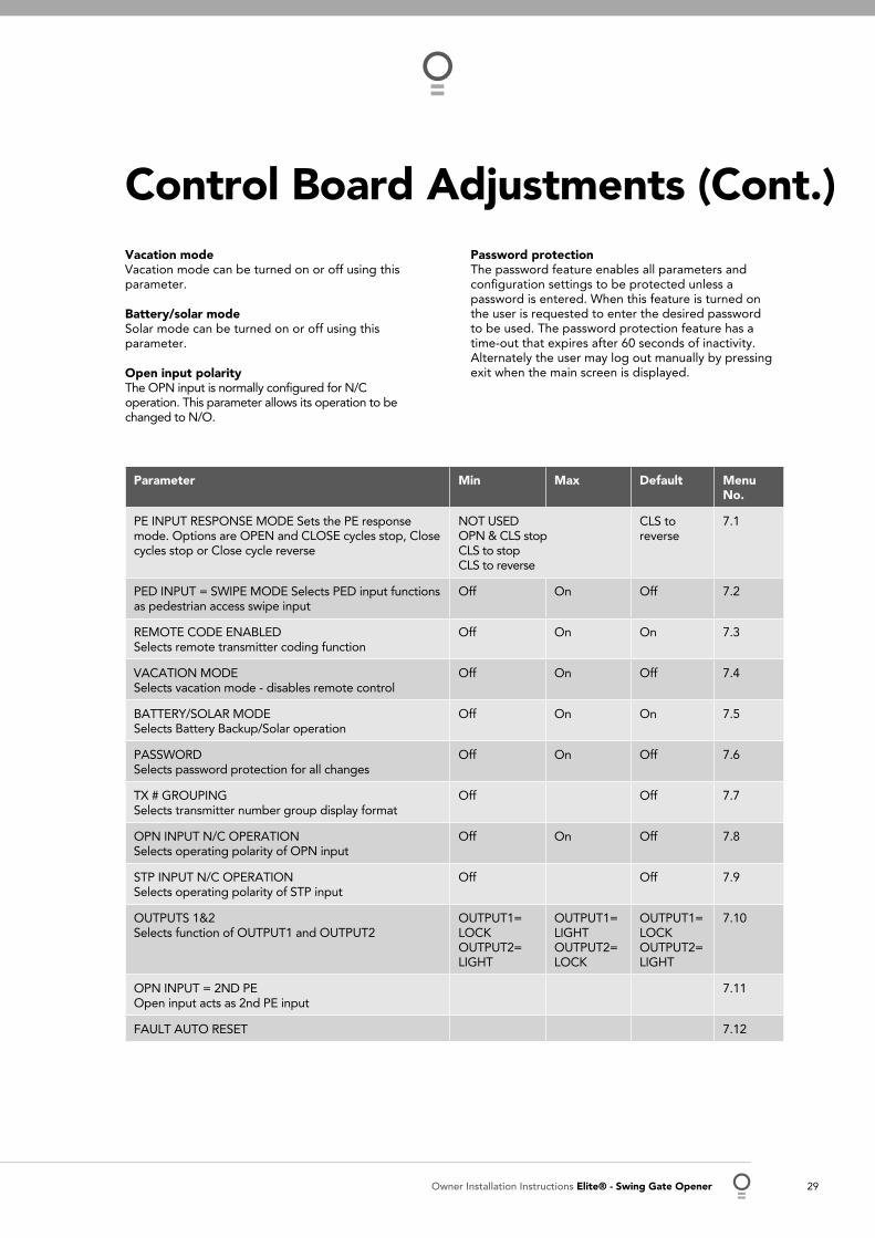
Parameter (Limit Switch) Min Max Default Step Unit Menu No.
M1 MARGIN Sets obstruction detection margin for M1 0.0 5.0 0.7 0.1 AMPS 2
M2 MARGIN Sets obstruction detection margin for M2 0.0 5.0 0.7 0.1 AMPS 2
SETTLE TIME disable the obstruction detection in the start of the cycle
0.1 2.0 1.0 0.1 SEC 2
Control Board AdjustmentsDCB-05’s standard operation can be altered by editing various parameters. This section describes the parameters and the effect they have.
Menu 2. Current Trips The obstruction margins are used to alter the sensitivity of the allowable variation between the “normal” speed profi le and DCB-05 to obstructions. Increasing the value increases the force required to detect an obstruction.
Standard Operation Modes
26 Elite® - Swing Gate Opener Owner Installation Instructions
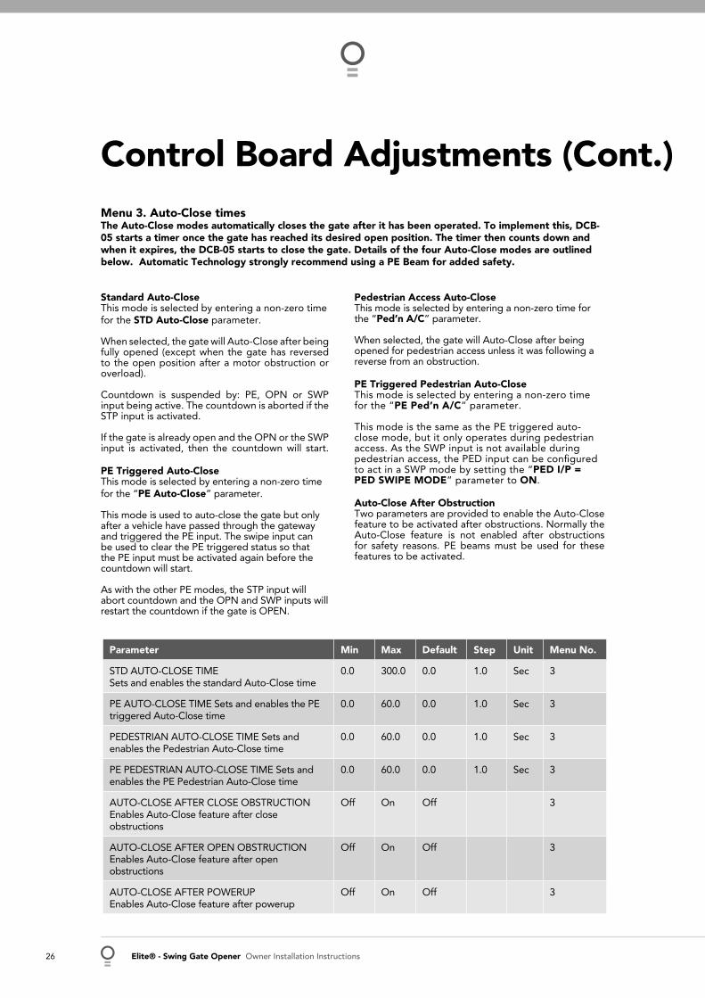
Menu 3. Auto-Close times The Auto-Close modes automatically closes the gate after it has been operated. To implement this, DCB-05 starts a timer once the gate has reached its desired open position. The timer then counts down and when it expires, the DCB-05 starts to close the gate. Details of the four Auto-Close modes are outlined below. Automatic Technology strongly recommend using a PE Beam for added safety.
Standard Auto-Close This mode is selected by entering a non-zero time for the STD Auto-Close parameter.
When selected, the gate will Auto-Close after being fully opened (except when the gate has reversed to the open position after a motor obstruction or overload).
Countdown is suspended by: PE, OPN or SWP input being active. The countdown is aborted if the STP input is activated.
If the gate is already open and the OPN or the SWP input is activated, then the countdown will start.
PE Triggered Auto-Close This mode is selected by entering a non-zero time for the “PE Auto-Close” parameter.
This mode is used to auto-close the gate but only after a vehicle have passed through the gateway and triggered the PE input. The swipe input can be used to clear the PE triggered status so that the PE input must be activated again before the countdown will start.
As with the other PE modes, the STP input will abort countdown and the OPN and SWP inputs will restart the countdown if the gate is OPEN.
Parameter Min Max Default Step Unit Menu No.
STD AUTO-CLOSE TIME Sets and enables the standard Auto-Close time
0.0 300.0 0.0 1.0 Sec 3
PE AUTO-CLOSE TIME Sets and enables the PE triggered Auto-Close time
0.0 60.0 0.0 1.0 Sec 3
PEDESTRIAN AUTO-CLOSE TIME Sets and enables the Pedestrian Auto-Close time
0.0 60.0 0.0 1.0 Sec 3
PE PEDESTRIAN AUTO-CLOSE TIME Sets and enables the PE Pedestrian Auto-Close time
0.0 60.0 0.0 1.0 Sec 3
AUTO-CLOSE AFTER CLOSE OBSTRUCTION Enables Auto-Close feature after close obstructions
Off On Off 3
AUTO-CLOSE AFTER OPEN OBSTRUCTION Enables Auto-Close feature after open obstructions
Off On Off 3
AUTO-CLOSE AFTER POWERUP Enables Auto-Close feature after powerup
Off On Off 3
Control Board Adjustments (Cont.)
Pedestrian Access Auto-Close This mode is selected by entering a non-zero time for the “Ped’n A/C” parameter.
When selected, the gate will Auto-Close after being opened for pedestrian access unless it was following a reverse from an obstruction.
PE Triggered Pedestrian Auto-Close This mode is selected by entering a non-zero time for the “PE Ped’n A/C” parameter.
This mode is the same as the PE triggered auto-close mode, but it only operates during pedestrian access. As the SWP input is not available during pedestrian access, the PED input can be confi gured to act in a SWP mode by setting the “PED I/P = PED SWIPE MODE” parameter to ON. Auto-Close After Obstruction Two parameters are provided to enable the Auto-Close feature to be activated after obstructions. Normally the Auto-Close feature is not enabled after obstructions for safety reasons. PE beams must be used for these features to be activated.
Owner Installation Instructions Elite® - Swing Gate Opener 27
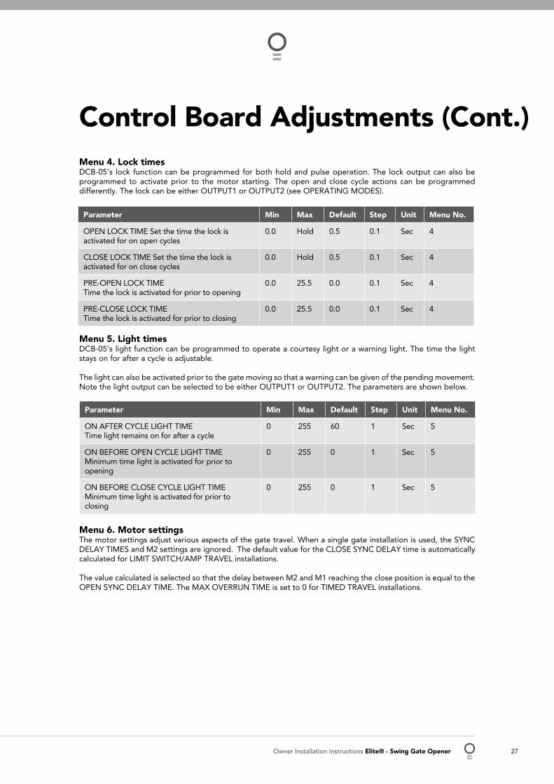
Menu 4. Lock times DCB-05’s lock function can be programmed for both hold and pulse operation. The lock output can also be programmed to activate prior to the motor starting. The open and close cycle actions can be programmed differently. The lock can be either OUTPUT1 or OUTPUT2 (see OPERATING MODES).
Parameter Min Max Default Step Unit Menu No.
OPEN LOCK TIME Set the time the lock is activated for on open cycles
0.0 Hold 0.5 0.1 Sec 4
CLOSE LOCK TIME Set the time the lock is activated for on close cycles
0.0 Hold 0.5 0.1 Sec 4
PRE-OPEN LOCK TIME Time the lock is activated for prior to opening
0.0 25.5 0.0 0.1 Sec 4
PRE-CLOSE LOCK TIME Time the lock is activated for prior to closing
0.0 25.5 0.0 0.1 Sec 4
Menu 5. Light times DCB-05’s light function can be programmed to operate a courtesy light or a warning light. The time the light stays on for after a cycle is adjustable.
The light can also be activated prior to the gate moving so that a warning can be given of the pending movement. Note the light output can be selected to be either OUTPUT1 or OUTPUT2. The parameters are shown below.
Parameter Min Max Default Step Unit Menu No.
ON AFTER CYCLE LIGHT TIME Time light remains on for after a cycle
0 255 60 1 Sec 5
ON BEFORE OPEN CYCLE LIGHT TIME Minimum time light is activated for prior to opening
0 255 0 1 Sec 5
ON BEFORE CLOSE CYCLE LIGHT TIME Minimum time light is activated for prior to closing
0 255 0 1 Sec 5
Menu 6. Motor settings The motor settings adjust various aspects of the gate travel. When a single gate installation is used, the SYNC DELAY TIMES and M2 settings are ignored. The default value for the CLOSE SYNC DELAY time is automatically calculated for LIMIT SWITCH/AMP TRAVEL installations.
The value calculated is selected so that the delay between M2 and M1 reaching the close position is equal to the OPEN SYNC DELAY TIME. The MAX OVERRUN TIME is set to 0 for TIMED TRAVEL installations.
Control Board Adjustments (Cont.)

28 Elite® - Swing Gate Opener Owner Installation Instructions
Parameter Min Max Default Step Unit Menu No.
CLOSE SYNC DELAY TIME Time delay between M2 and M1 closing
0.0 25.5 2.0 0.1 SEC 6.1
OPEN SYNC DELAY TIME Time delay between M1 and M2 opening
0.0 25.5 2.0 0.1 SEC 6.2
OPEN SPEED VOLTSVoltage applied to motors when opening
12 24 22 1 VOLTS 6.3
CLOSE SPEED VOLTSVoltage applied to motors when closing
12 24 20 1 VOLTS 6.4
SLOW SPEED VOLTSVoltage applied to motors when slowing down
6 24 8 1 VOLTS 6.5
SLOW TIMEThe time between slow down and end of cycle
0.1 10.0 3.0 0.1 SEC 6.6
HOMING / SETUP SPEED VOLTSVoltage applied to motors when setting up the travel limits
12 24 Norm 1 Volts 6.7
STOP PAUSE TIMEPause time used between motor direction changes
0.0 2.0 0.2 0.1 SEC 6.8
M1 NORMAL OPEN TIMENormal open time for motor 1
0.0 60.0 0.0 0.1 SEC 6.9
M1 NORMAL CLOSE TIMENormal close time for motor 1
0.0 60.0 0.0 0.1 SEC 6.10
M2 NORMAL OPEN TIMENormal open time for motor 2
0.0 60.0 0.0 0.1 SEC 6.11
M2 NORMAL CLOSE TIMENormal close time for motor 2
0.0 60.0 0.0 0.1 SEC 6.12
MAX OVERRUN TIMEExtra time allowed for cycle to complete (beyond normal cycle time)
0 60 5 1 6.13
Menu 7. Operating modes
PE input response mode The PE input can be confi gured to respond in one of three modes.
Open and close cycles stop In this mode, all cycles are prevented from being completed or initiated when the PE input is active.
Close cycles stop In this mode, the PE input has no effect when opening but will stop the gate when closing.
Reverses close cycles In this mode, the PE input has no effect when opening but will cause the gate to reverse if activated when closing.
PED input function The PED input can be confi gured to a SWIPE type input for pedestrian access. This provides full functionality with the PE Triggered Pedestrian Auto-Close function.
Remote code DCB-05 supports the Remote Code Set feature. This parameter can be used to disable the feature for security or transmitter management reasons.
Control Board Adjustments (Cont.)
Owner Installation Instructions Elite® - Swing Gate Opener 29
Vacation mode Vacation mode can be turned on or off using this parameter.
Battery/solar mode Solar mode can be turned on or off using this parameter.
Open input polarity The OPN input is normally confi gured for N/C operation. This parameter allows its operation to be changed to N/O.
Password protection The password feature enables all parameters and confi guration settings to be protected unless a password is entered. When this feature is turned on the user is requested to enter the desired password to be used. The password protection feature has a time-out that expires after 60 seconds of inactivity. Alternately the user may log out manually by pressing exit when the main screen is displayed.
Parameter Min Max Default Menu No.
PE INPUT RESPONSE MODE Sets the PE response mode. Options are OPEN and CLOSE cycles stop, Close cycles stop or Close cycle reverse
NOT USEDOPN & CLS stopCLS to stopCLS to reverse
CLS to reverse
7.1
PED INPUT = SWIPE MODE Selects PED input functions as pedestrian access swipe input
Off On Off 7.2
REMOTE CODE ENABLED Selects remote transmitter coding function
Off On On 7.3
VACATION MODE Selects vacation mode - disables remote control
Off On Off 7.4
BATTERY/SOLAR MODE Selects Battery Backup/Solar operation
Off On On 7.5
PASSWORD Selects password protection for all changes
Off On Off 7.6
TX # GROUPINGSelects transmitter number group display format
Off Off 7.7
OPN INPUT N/C OPERATION Selects operating polarity of OPN input
Off On Off 7.8
STP INPUT N/C OPERATIONSelects operating polarity of STP input
Off Off 7.9
OUTPUTS 1&2Selects function of OUTPUT1 and OUTPUT2
OUTPUT1=LOCKOUTPUT2=LIGHT
OUTPUT1=LIGHTOUTPUT2=LOCK
OUTPUT1=LOCKOUTPUT2=LIGHT
7.10
OPN INPUT = 2ND PEOpen input acts as 2nd PE input
7.11
FAULT AUTO RESET 7.12
Control Board Adjustments (Cont.)
30 Elite® - Swing Gate Opener Owner Installation Instructions
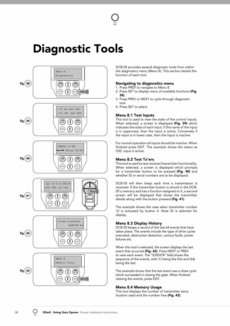
Diagnostic ToolsDCB-05 provides several diagnostic tools from within the diagnostics menu (Menu 8). This section details the function of each tool.
Navigating to diagnostics menu 1. Press PREV to navigate to Menu 8.2. Press SET to display menu of available functions (Fig.
38). 3. Press PREV or NEXT to cycle through diagnostic
tool. 4. Press SET to select.
Menu 8.1 Test Inputs This tool is used to view the state of the control inputs. When selected, a screen is displayed (Fig. 39) which indicates the state of each input. If the name of the input is in uppercase, then the input is active. Conversely if the input is in lower case, then the input is inactive.
For normal operation all inputs should be inactive. When fi nished press EXIT. The example shows the status as OSC input is active.
Menu 8.2 Test Tx’ers This tool is used to test receiver/transmitter functionality. When selected, a screen is displayed which prompts for a transmitter button to be pressed (Fig. 40) and whether ID or serial numbers are to be displayed.
DCB-05 will then beep each time a transmission is received. If the transmitter button is stored in the DCB-05’s memory and has a function assigned to it, a second screen will be displayed that shows the transmitter details along with the button pressed (Fig. 41).
The example shows the case when transmitter number 12 is activated by button 4. Note ID is selected for display.
Menu 8.3 Display History DCB-05 keeps a record of the last 64 events that have taken place. The events include the type of drive cycles executed, obstruction detection, various faults, power failures etc.
When this tool is selected, the screen displays the last event that occurred (Fig. 42). Press NEXT or PREV to view each event. The “EVENT#” fi eld shows the sequence of the events, with (1) being the fi rst and (64) being the last.
The example shows that the last event was a close cycle which succeeded in closing the gate. When fi nished viewing the events, press EXIT.
Menu 8.4 Memory Usage This tool displays the number of transmitter store location used and the number free (Fig. 43).
PREV NEXT
EXIT SET
Diagnostics
MENU 8
PRESS
40fi g
PREV NEXT
EXIT SET
cls osc swp ped
I/P pe opn stp
41fi g
42fi g
43fi gPREV NEXT
EXIT SET
Memory Tools
MENU 9
PRESS
PREV NEXT
EXIT SET
EVENT# 64
Close Complete
PREV NEXT
EXIT SET
OSC PED LGT>VAC
124 ID B B SMITH
PRESS
39fi g
PREV NEXT
EXIT SET
/ Shows ID/SN
PRESS TX’ER
38fi g
Owner Installation Instructions Elite® - Swing Gate Opener 31
PREV NEXT
EXIT SET
(CYCLES) 60000
Service Counter
PREV NEXT
EXIT SET
1234
1:Open Cycles
45fi g
44fi g
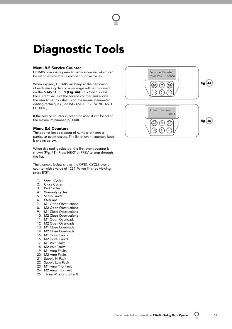
Menu 8.5 Service Counter DCB-05 provides a periodic service counter which can be set to expire after a number of drive cycles.
When expired, DCB-05 will beep at the beginning of each drive cycle and a message will be displayed on the MAIN SCREEN (Fig. 44). This tool displays the current value of the service counter and allows the user to set its value using the normal parameter editing techniques (See PARAMETER VIEWING AND EDITING).
If the service counter is not to be used it can be set to the maximum number (60,000).
Menu 8.6 Counters The opener keeps a count of number of times a particular event occurs. The list of event counters kept is shown below.
When this tool is selected, the fi rst event counter is shown (Fig. 45). Press NEXT or PREV to step through the list.
The example below shows the OPEN CYCLE event counter with a value of 1234. When fi nished viewing press EXIT.
Open CyclesClose CyclesPed CyclesWarranty cyclesSetup LimitsOverlapsM1 Open ObstructionsM2 Open Obstructions M1 Close ObstructionsM2 Close Obstructions M1 Open OverloadsM2 Open OverloadsM1 Close Overloads M2 Close OverloadsM1 Drive FaultsM2 Drive Faults M1 Volt FaultsM2 Volt FaultsM1 Amp FaultsM2 Amp Faults Supply Hi FaultSupply Low FaultM1 Amp Trip FaultM2 Amp Trip FaultThree Wire Limits Fault
1.2.3.4.5.6.7.8.9.10.11.12.13.14.15.16.17.18.19.20.21.22.23.24.25.
Diagnostic Tools

32 Elite® - Swing Gate Opener Owner Installation Instructions
The Memory Tools accessed from within Menu 9 are used to backup, restore or clear the controller. Once selected, the PREV or NEXT buttons can be used to view the Memory Tool options. To execute the displayed option simply press SET (Fig. 46).
Menu 9.1 Clr Control This option will clear the gate control memory and reload the factory set defaults for parameters such as the lock time, light time, Auto-Close times etc. It will also clear the travel limits.
Menu 9.2 Clr Tx’ers This option will clear the transmitter storage memory.
Memory Tools
PREV NEXT
EXIT SET
Memory Tools
MENU 9
PRESS
46fi g
DCB-05 can be instructed, via its pedestrian control feature, to partly open and provide pedestrian access but prevent vehicle access. This is achieved by partly opening the motor 1 gate leaf.
If dual motors are used, motor 2’s gate leaf is held closed. The partly open position of motor 1’s gate leaf is initially set to fi ve (5) seconds from fully closed position. This initial position can be adjusted by the installer to any position within the gates travel range by selecting a pedestrian access travel time (from closed). The setting is accessed from “MENU 10.4 Set Pedestrian” (Fig. 47).
The time is adjustable in 1 second steps.
Step 1. Navigating to “set pedestrian menu” 1. Press PREV to navigate to Menu 10 2. Press SET - MENU 10.1 is displayed. 3. Press NEXT to go to MENU 10.4. 4. Press SET to enter Set Pedestrian procedure (Fig. 48).
Step 2. Setting pedestrian position 1. Press OPEN or CLOSE to adjust pedestrian drive time. 2. Press SET to record position 3. Press transmitter coded for pedestrian function or push
button wired into pedestrian input to test.
Setting Pedestrian Position
PREV NEXT
EXIT SET
Set Pedrestrian
MENU 10.4
PRESS
PREV NEXT
EXIT SET
Time 5
Ped’n Opening
47fi g
48fi g

Owner Installation Instructions Elite® - Swing Gate Opener 33
PE Beam Installation
49fi g
50fi g
51fi g
Fitting Photo Electric (PE) Beams Attach the mounting bracket (4) to adjustment bracket (3) with the pan head screw (6) (supplied) (Fig. 49).Attach the PE 2000TS bracket (2) to PE beam transmitter (IR-200TS-TX) with four taptite screws (m3x5) and attach the other side to adjustment bracket (3) with the pan head screw (6) (supplied).Repeat steps a and b to assemble the PE Beam receiver ( IR-200TS-RX).
Locate the Photo Electric (PE) Beams in a strategic location in the gateway. Automatic Technology recommend that the sensor is placed 150 mm above the fl oor level. Connect as per the wiring diagram (Fig. 51). Use 5.6 kilo ohm resistor with the colour code green, blue, red and gold on the PE Beams receiver between the V- and NC terminals as shown in (Fig. 51).
AlignmentPower up the PE Beams. The green LED on the transmitter and red LED on the receiver should turn ON to indicate power is present.If the receiver is connected to power and the red LED is on while the green LED is on, the transmitter and receiver are not aligned.Make horizontal and/or vertical (Fig. 50) adjustment on the transmitter and/or receiver until the red LED turns off on the receiver, indicating alignment.
WARNING: Tampering with the PE Beams could result in serious personal injury and/or property damage and will void the warranty.
a.
b.
c.
a.
b.
c.
1
2
34
6
5
RED
BLACK
RED
BLACK
RED
BLACK
YELLOW
R1=5.6K OHM Green,Blue,Red,Gold.25WATT 5% TOLERENCERESISTANCE
R1
YELLOWBLACK
V- IN V+P.E BEAM
R1

34 Elite® - Swing Gate Opener Owner Installation Instructions
Wiring Output1 And Output2Outputs 1 and 2 are used to control a lock and a light. Which output is to control which function and the way it is controlled, is programmable.
If using these outputs make sure that the functions are confi gured for correct operation prior to setting the travel limits.
OUTPUT1 is a relay output with high current capability. OUTPUT2 is used to activate an optional external relay module (RO-1) which in turn is used to switch the load.
Fitting solenoid or magnetic locks Install the lock mechanism on the gate as per the manufacturers instructions. The wiring diagram on the left is a representation of a typical lock with a bias for normally closed contact (Fig. 52).
Fitting courtesy lights An AC or DC courtesy light can be activated via an output on the gate opener control board. Connect the light as per the diagram on the left (Fig. 53).
WARNING: A qualifi ed electrician must perform the installation where 240V AC power is used.
Wiring Control Inputs The console switch inputs may be used for operating the gate via any device that provides and switch contact output.
AUX, OPN, STP, CLS, SWP, PED requires normally open contact switches (Fig. 54). OPN and STP inputs can be confi gured to take normally close contact switches.
53fi g
52fi g
Accessories Installation
SUITABLE POWER SUPPLY + -
OUT1 N/COUT1 COMMONOUT1 N/O
STOPCLOSEOSCSWIPEPEDESTRIANCOMMONOUT2 +OUT2 -
LIG
HT
RELA
Y M
OD
ULE
PO
WER
SUPP
LY
OUT1 N/COUT1 COMMONOUT1 N/O
V+INV-AUXOPENSTOPCLOSEOSCSWIPEPEDESTRIANCOMMONOUT2 +OUT2 -
OUT1 N/COUT1 COMMONOUT1 N/O
P.E BEAM
54fi g

Owner Installation Instructions Elite® - Swing Gate Opener 35
Battery Backup InstallationConnect the Battery Backup Kit
Disconnect power to the DCB-05.Secure the SBY-3 Charger Board in the control box with sticky pads (supplied with the battery charger kit part number # 90188).Connect the SBY-3 charger board to battery box and to DCB-05 as shown (Fig. 55).Reconnect power.From menu 7.9 select the “battery enabled option”
Testing Battery BackupPress transmitter to test the gate opener.Whilst gate is in motion, disconnect mains power. The gate should continue to operate as normal.
NOTE: Wait for the gate to complete its travel.
Press the transmitter to activate the gate.Whilst gate is in motion re-connect power. The gate should complete the cycle as normal.
TroubleshootingIf gate stops or moves very slowly under battery power, the batteries may be weak or have no charge. Connect mains power and allow the batteries to charge. This may take 24 - 48 hours to reach maximum charge capacity.
1.2.
3.
4.5.
1.2.
3.4.
55fi g

36 Elite® - Swing Gate Opener Owner Installation Instructions
Gate does not open or close Check that power is still available at mains power point.Check that Control Box is plugged into mains power.Check that motor is engaged for automatic operation.Check all wiring from motor and microswitches to the control board are sound.
Gate reverses while closing or stops while opening
Check obstruction overload sensitivity adjustment.Check for obstructions.Disengage the drive unit to manual and check the gate is in good working order.If a P.E. beam is fi tted, ensure it is clear of obstructions or dirt on the lens.
Transmitter not functioning New transmitters must be coded to the receiver.Check/change the battery in the transmitter (LED fl ashes to indicate low battery).Having the antenna behind a structure (gate or fence) or not in line of sight may reduce optimal range/reception.Interference from external/outside sources such as baby monitors, or radio transmitter etc. The best solution is to remove the source causing the interference.
Gate and/or opener requires service
Contact the installer of the opener or local ATA dealer for service. They will be able to inspect, service, adjust or repair the gate and opener as necessary.
Troubleshooting guide

Owner Installation Instructions Elite® - Swing Gate Opener 37
Specifi cation
Drive unit
Motor Voltage 24V DC
Maximum Pulling Force 200N (20Kg)
Drive Arm Rotation Speed Approx. 8°/sec
Dimensions 135W x 290H x 230D (mm)
Weight 13Kg (incl. arms)
Max Weight Of The Gate 250 kg¹
Control Box
Protection rating 24V DC
24VDC accessory output 24VDC (unfi ltered) 3Amp maximum
Secondary voltage: 24V AC 150 VA
Receiver type: 433.92 MHz TrioCode™ or Tri-Tran™ 2
Receiver code storage capacity: 511 x 4 Button Transmitter Codes
Transmitter frequency: UHF Multi-frequency FM Transmitter
Coding type: Hopping Code
Code generation: Non-linear encryption algorithm
Transmitter battery: CR2032
Note:The maximum weight gate that the opener can be installed on 250Kg. The gate must be well balanced. A person of limited strength should be able to move the gate manually with very little effort (15Kg force max.) in case of an emergency.The fi rst memory location sets the type of transmitters which can be stored into the receivers memory. It either can be ATA TrioCode™ or B&D Tri-Tran™ transmitters.
1.
2.

38 Elite® - Swing Gate Opener Owner Installation Instructions
Spare Parts List

Owner Installation Instructions Elite® - Swing Gate Opener 39
1. This Warranty is given by Automatic Technology (Australia) Pty Ltd (ABN 11 007 125 368) (ATA), 6-8 Fiveways Boulevard, Keysborough 3173, 1300 133 944, [email protected]
2. The Competition and Consumer Act 2010 (including the Australian Consumer Law) and other relevant statutes provide a set of statutory consumer guarantees and other legal rights that cannot be excluded, restricted or modifi ed by contract. This Warranty is in addition to and does not affect any of your rights under the Australian Consumer Law and other relevant statutes.
3. Our goods come with guarantees that cannot be excluded under the Australian Consumer Law. You are entitled to a replacement or refund for a major failure and for compensation of any other reasonably foreseeable loss or damage. You are also entitled to have the goods repaired or replaced if the goods fail to be of acceptable quality and the failure does not amount to a major failure.
4. Subject to your non-excludable rights under the Australian Consumer Law, ATA expressly excludes any liability for consequential loss, incidental or indirect damages (including but not limited to damages for loss of business profi ts, business interruption and loss of business information) due to a defect of the SGO-1 Elite® (Product). In particular any loss or damage caused to other equipment or accessories used with the product or any loss resulting from a delay in repair is excluded to extent permitted by law.
5. Subject to all of the matters set out below, ATA warrants in relation to the Product that:
(a) the Product’s drive units will be free of any defects in material and workmanship for at least 12 months after the date of purchase (as evidenced by the sales docket receipt), or 2,500 cycles, which ever occurs fi rst; and
(b) the Product’s other components and accessories will be free of any defects in material and workmanship for at least 12 months after the date of purchase (as evidenced by the sales docket receipt).
6. No additional warranty will apply for Products repaired during the relevant warranty period.
7. For all Products repaired outside the warranty period, a six (6) month warranty that the Product will be free of any defects in material and workmanship will apply from the date of dispatch of the Product to you. ATA may charge you for any repairs undertaken outside the warranty period, and will provide you with a quotation in relation to any such costs for your approval before proceeding with any repairs.
8. This Warranty applies only where you:(a) immediately notify ATA at the contact details provided
in paragraph 1 above or notify the or the retailer that you purchased the Product from of the alleged defect;
(b) return the product to the retailer that you purchased the Product from; and
(c) present the relevant sales docket and this Warranty document to the retailer to confi rm the date of purchase.
9. Except for this Warranty, ATA gives no warranties of any kind whatsoever (whether express or implied), in relation to the product, and, subject to paragraph 1 above, all warranties of whatsoever kind relating to the product are hereby excluded.
10. This Warranty excludes damage resulting from:(a) normal wear and tear;(b) accidental damage;(c) incorrect installation of the Product;(d) blown fuses, electrical surges, power surges or power spikes;(e) theft, fi re, fl ood, rain, water, lightning, storms or any other acts
of God;(f) any installation, confi guration or use of the Product contrary to
the instructions supplied with the Product;(g) maximum continuous operating time exceeding 1 minute in 10;
(h) the operating force exceeding 15kg* (150 Newton) when moving the door or gate manually to the open or closed position;
(i) residential gate weight exceeding 300kg;(j) the gate used with the Product not being in safe working order and
condition;(k) repairs which are not authorised by ATA;(l) any failure to install or maintain the Product in accordance with the
instructions supplied with the Product;(m) any use which is not in accordance with the instructions provided
with the Product;(n) deliberate or negligent damage to the Product;(o) any unauthorised modifi cation to the Product;(p) faulty or unsuitable wiring in the building in which the Product is
installed;(q) damage caused by insects;(r) any cost or expense relating to the recall of the Product;(s) installation of a residential gate opener in a commercial or industrial
situation or in a dwelling other than a single-family dwelling;(t) radio or electrical interference; or(u) acts or omissions of any person (including service providers
approved by ATA) other than ATA.11. ATA’s liability under this Warranty is limited, at ATA’s absolute
option, to replacing or repairing the product which ATA, in its unfettered opinion, considers to be defective either in material and/or workmanship or to credit the dealer with the price at which the product was purchased by the dealer.
12. This Warranty does not extend to cover labour for installation of the Product following repairs, the cost of which must be borne by you.
13. This Warranty is limited to Return-to-Base (RTB) repair and does not cover labour for on-site attendance, the cost of which must be borne by you.
14. Except as specifi ed in this Warranty, ATA will not charge you for any repairs or replacements conducted under the Warranty. However, ATA will charge you for any repairs which are not within the scope of this Warranty (or which are not required to be undertaken free of charge pursuant to the Australian Consumer Law).
15. This Warranty is void if the Product is not returned to the manufacturer in original or suitably secure packaging.
16. This Warranty is only applicable for repairs to the product carried out within Australia.
17. This Warranty does not cover consumable items including, without limitation, globes, batteries and fuses.
18. This Warranty is not transferable. 19. Where the Product is retailed by any person other than ATA, except
for the warranty set out above, such person has no authority from ATA to give any warranty or guarantee on ATA’s behalf in addition to the warranty set out above.
20. Any provision of this Warranty that is prohibited or unenforceable in any jurisdiction is ineffective as to that jurisdiction to the extent of the prohibition or unenforceability. That does not invalidate the remaining provisions of this Warranty nor affect the validity or enforceability of that provision in any other jurisdiction.
21. Products presented for repair may be replaced by refurbished goods of the same type rather than being repaired. Refurbished parts may be used to repair the Product.
NOTES:1. One (1) cycle = one (1) open and one (1) close action of the door or
gate.2. This Warranty is to be read in conjunction with the owner’s copy of
the installation instruction manual.3. * The door or gate that the Product is used with should be balanced
in such a way that the user is able to open or close the door or gate manually using a force not greater than 150 Newton (15 kg), other than to initially cause the door or gate to start moving, which may require force in excess of that specifi ed in this paragraph.
Warranty and Exclusion of Liability

GARAGE DOOR OPENERS | GATE OPENERS | REMOTE CONTROL ACCESS SOLUTIONS
© December 2011 Automatic Technology (Australia) Pty Ltd. All rights reserved. Elite® is registered and TrioCode™ is the trademark of Automatic Technology (Australia) Pty Ltd. Tri-Tran™ is a trademark of B&D Doors and openers. No part of this document may be reproduced without prior permission. In an ongoing commitment to product quality we reserve the right to change specifi cation without notice. E&OE.
Automatic Technololgy (Australia) Pty LtdABN 11 007 125 368
6-8 Fiveways BoulevardKeysborough, Victoria, 3173, Australia
P 1300 133 944
+61 3 97910200 (International Enquiries Only)
www.ata-aust.com.au