mpe table lime rock park sc 2 ct - mpe 07.29
TRANSCRIPT
21003850-v1
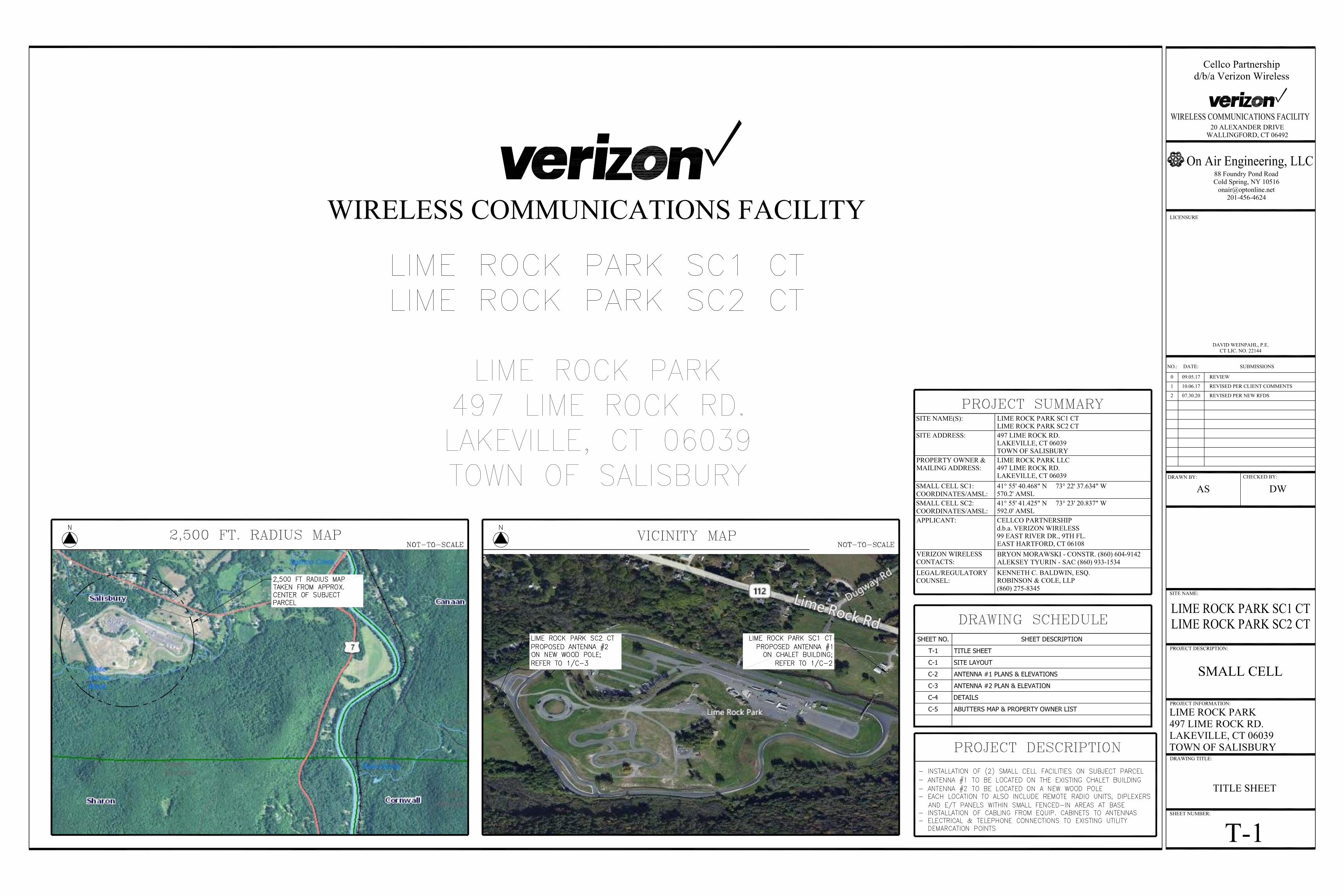
August 3, 2020 Melanie A. Bachman, Esq. Executive Director/Staff Attorney Connecticut Siting Council 10 Franklin Square New Britain, CT 06051 Re: Petition No. 1331 –Cellco Partnership d/b/a Verizon Wireless
Lime Rock Park, 497 Lime Rock Road, Lakeville, Connecticut
Request for Staff Approval of Minor Project Changes Dear Attorney Bachman:
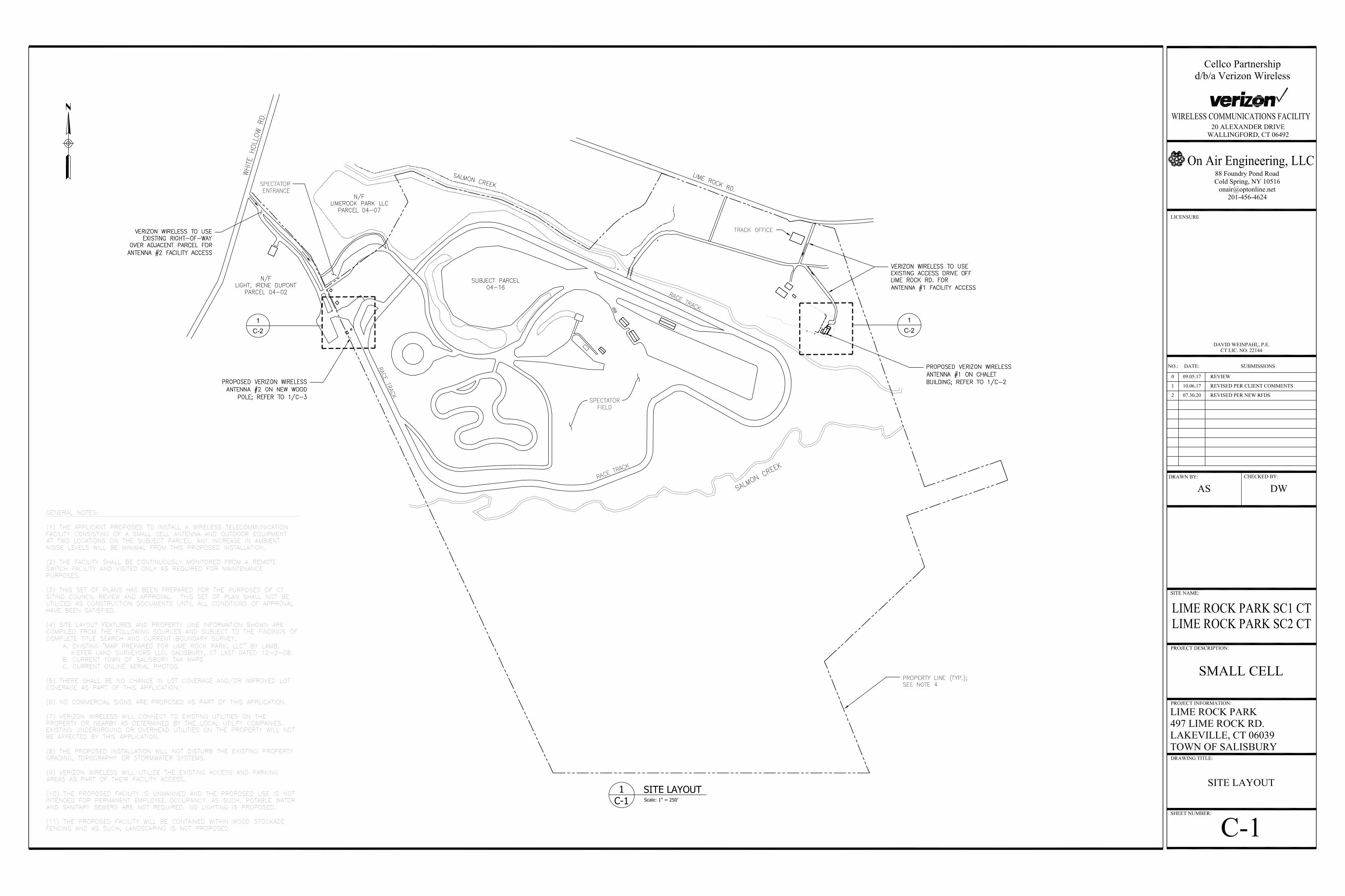
On December 7, 2017, the Siting Council approved Cellco’s Petition for a Declaratory Ruling to establish two small cell wireless facilities at Lime Rock Park in Lakeville, Connecticut. Recently, Cellco decided to change the model of the antenna it intends to use at each of the approved small cell locations. A copy of the new antenna model specification sheet is included in Attachment 1.
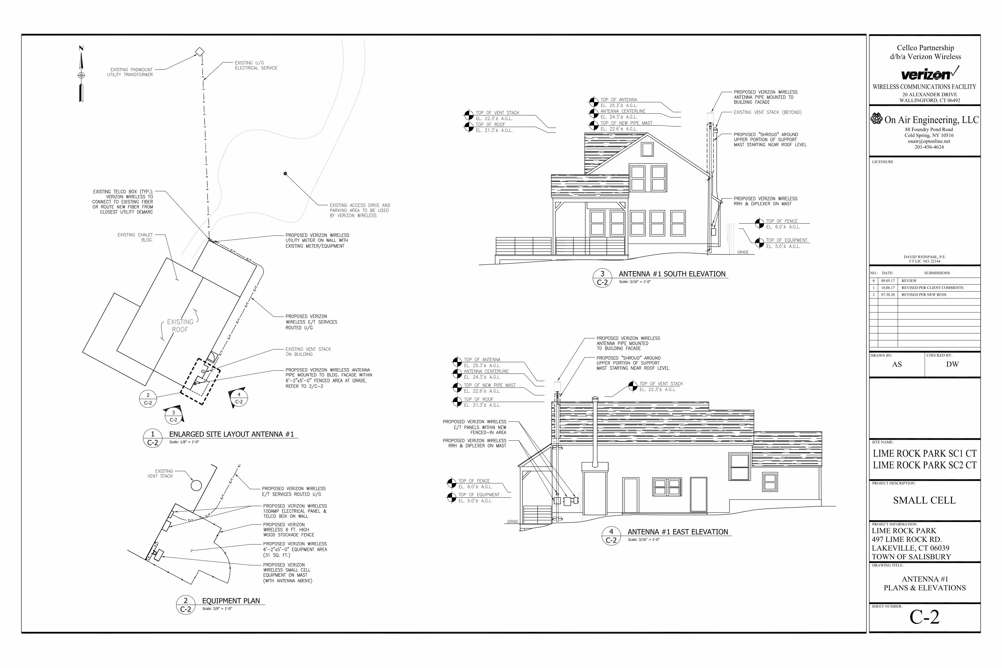
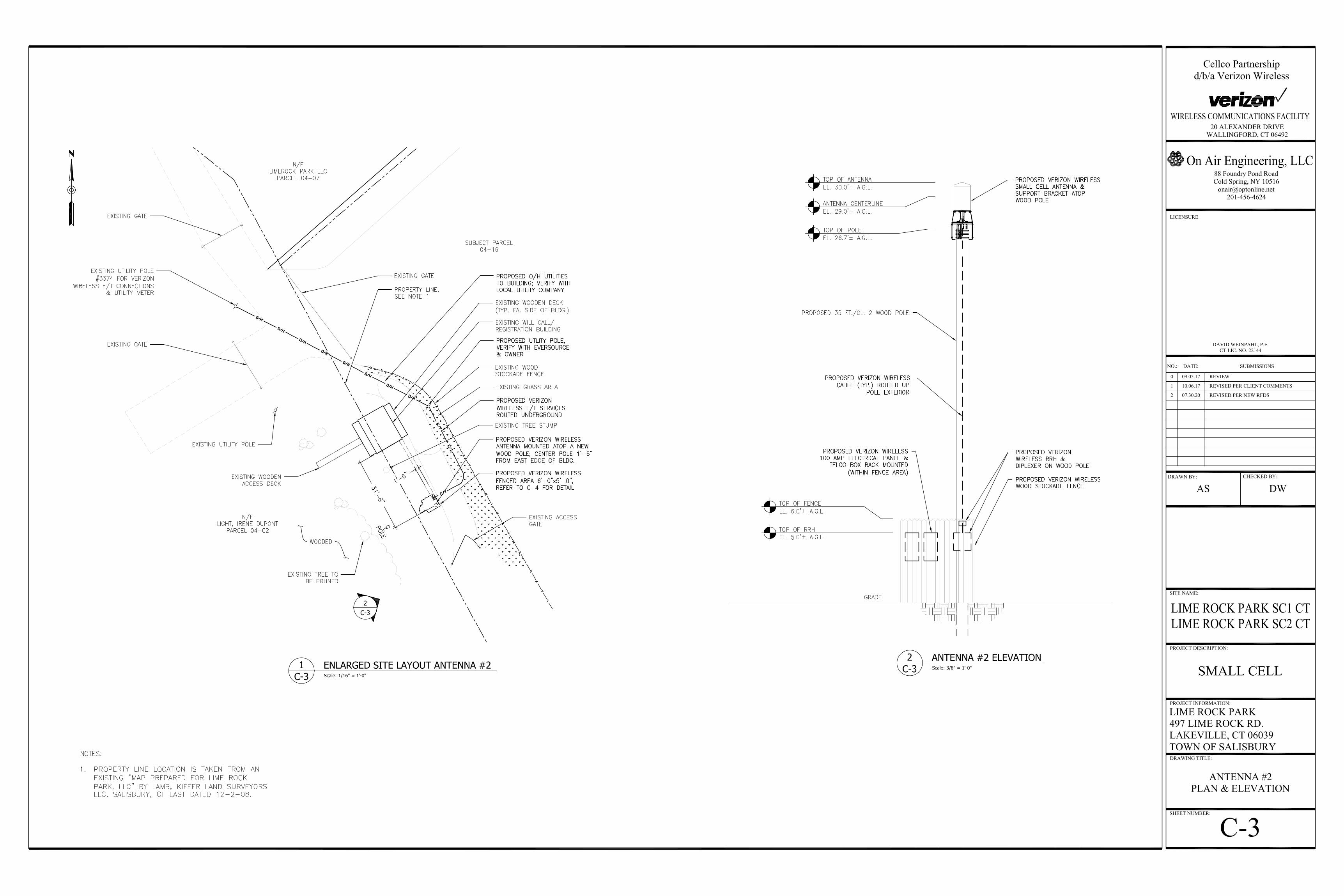
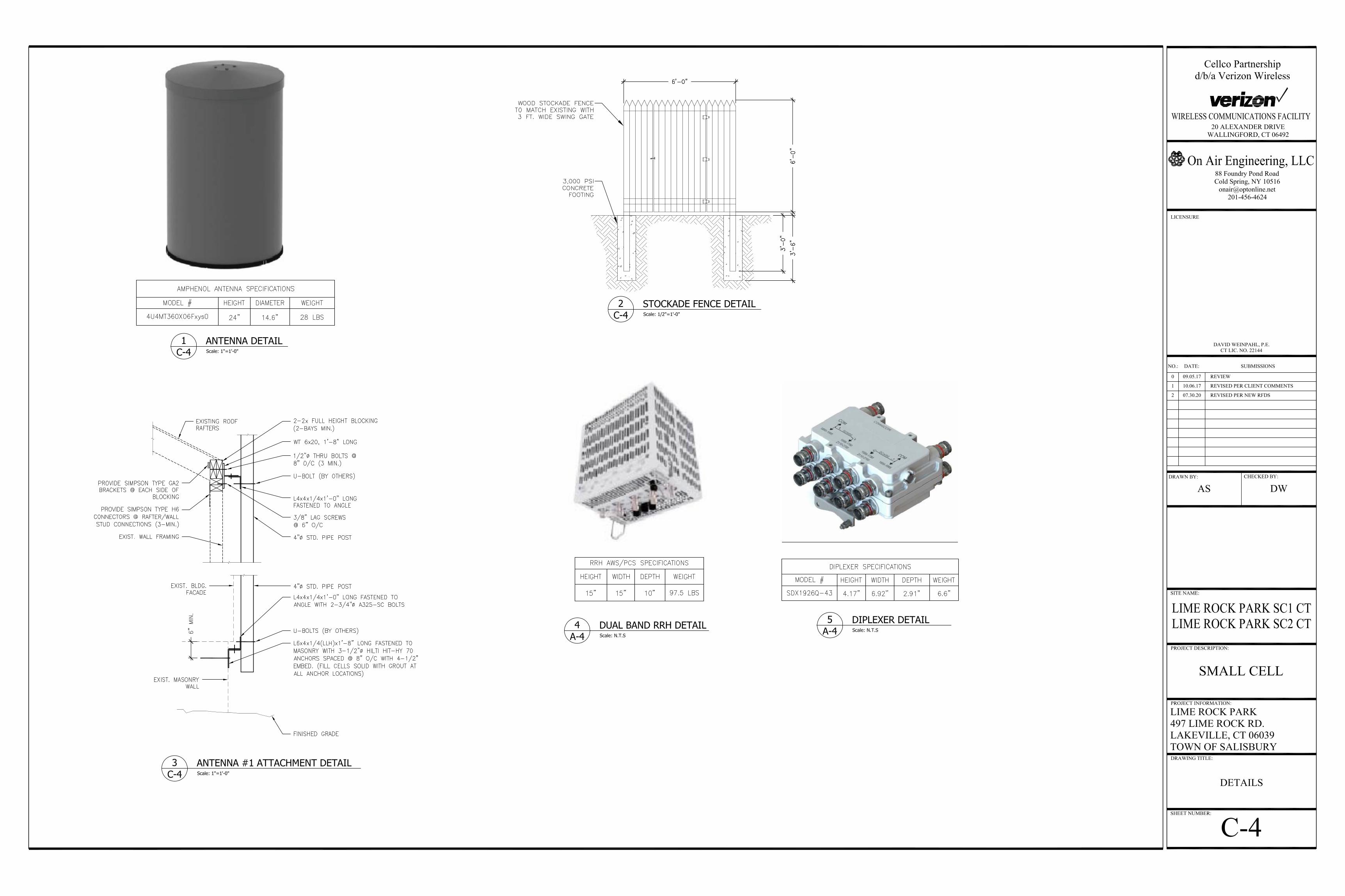
The location of the two approved facilities will not change and the overall height of each structure, to the top of the cannister antenna, will remain the same. The proposed antenna centerline height will be 24.3’ above grade at the Lime Rock Park SC 1 facility and 29’ above grade at the Lime Rock Park SC 2 facility. Project plans for both small cell facilities are included in Attachment 2.
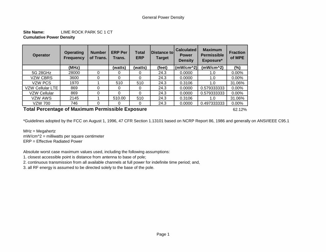
Radio frequency (“RF”) emissions from both proposed facilities, with the new antenna models, will continue to comply with the standards adopted by the Federal Communications Commission (“FCC”). Included in Attachment 3 are General Power Density tables that demonstrate that Lime Rock Park SC1 or Lime Rock Park SC2 Facilities will operate well within the FCC safety standard.
KENNETH C. BALDWIN 280 Trumbull Street Hartford, CT 06103-3597 Main (860) 275-8200 Fax (860) 275-8299 [email protected] Direct (860) 275-8345 Also admitted in Massachusetts and New York
August 3, 2020 Page 2
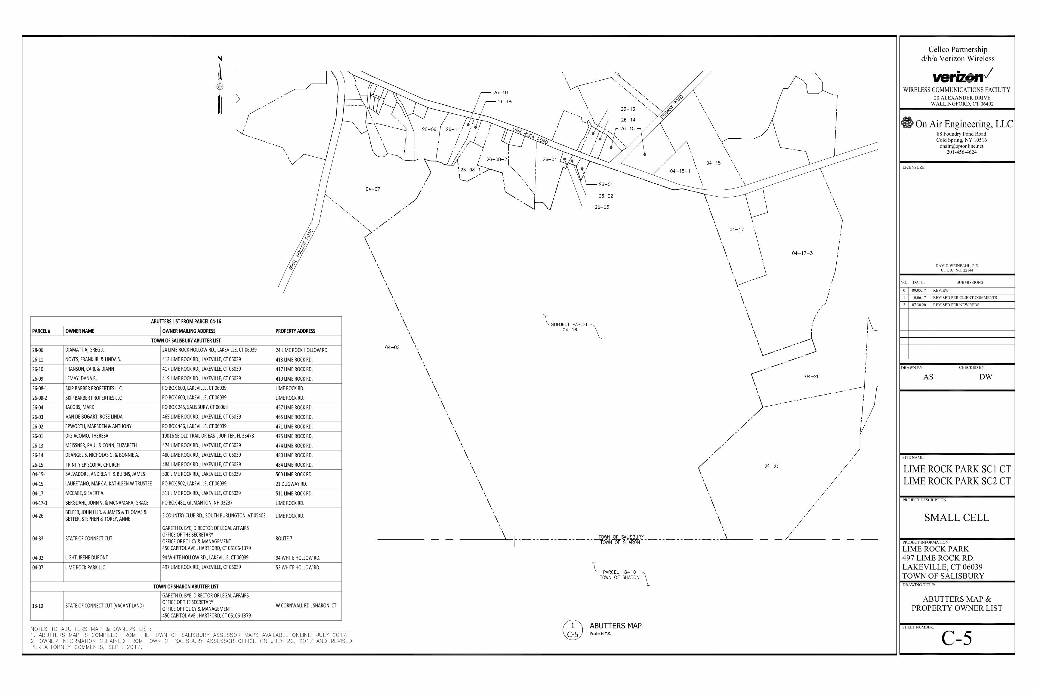
Cellco respectfully submits that, pursuant to Condition No. 3 of the Council’s December 7, 2017 approval, the proposed modifications described above are “minor project changes” that can be approved by Council staff. A copy of this correspondence was sent to Salisbury’s First Selectman Curtis Rand; Abby Conroy, Land Use Administrator; and Lime Rock Park LLC, the owner of the Property.
If you have any questions or need any additional information regarding this matter, please do not hesitate to contact me.
Sincerely,
Kenneth C. Baldwin
Copy to:
Corey Vaccaro

ATTACHMENT 1

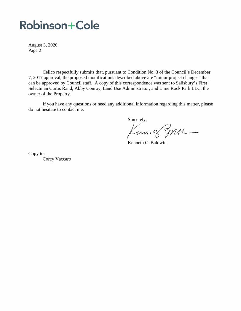
Connector DescriptionThe antenna has 16 connectors located at the bottom.
Mid Band #1 Y1 Pseudo Omni 1695-2700 MHz (2x) 4.3-10 Female
Mid Band #2 Y2 Pseudo Omni 1695-2700 MHz (2x) 4.3-10 Female
Mid Band #3 Y3 Pseudo Omni 1695-2700 MHz (2x) 4.3-10 Female
Mid Band #4 Y4 Pseudo Omni 1695-2700 MHz (2x) 4.3-10 Female
Mid Band #5 Y5 Pseudo Omni 3550-3700 MHz (2x) 4.3-10 Female
Mid Band #6 Y6 Pseudo Omni 3550-3700 MHz (2x) 4.3-10 Female
High Band #1 V1 Pseudo Omni 5150-5925 MHz (2x) 4.3-10 Female
High Band #2 V2 Pseudo Omni 5150-5925 MHz (2x) 4.3-10 Female
Electrical Characteristics Y1, Y2, Y3, Y4 Y5 Y6 V1 V2
Frequency Bands (MHz)(4x) 1695-2700
(2x) 3550-3700 (2x) 5150-59251695-1880 1850-1990 1920-2200 2300-2700
Polarization (4x) ±45° (2x) ±45° (2x) ±45°
Horizontal Beamwidth 360° 360° 360° 360° 360° 360°
Vertical Beamwidth 23.4° ± 4.2° 21.7° ± 4.3° 20.9° ± 4.3° 17.1° ± 3.2° 37.1° ± 10.6° 22.9° ± 5.1°
Gain 9.1 ± 0.5 dBi 8.9 ± 0.4 dBi 9.1 ± 0.7 dBi 9.6 ± 0.6 dBi 5.2 ± 0.5 dBi Avg. 5.1 dBiMax. 5.8 dBi
Electrical Downtilt (°) (x) 2, 4, 6 (y) 0 (y) 0
Impedance 50Ω 50Ω 50Ω
VSWR ≤ 1.5:1 ≤ 1.5:1 ≤ 1.5:1
Upper Sidelobe Suppression > 14 dB N/A > 13 dB
IsolationIntraband 25 dB 25 dB 25 dB
Interband 28 dB 28 dB 28 dB
IM3 (2x20W carrier) < -153 dBc N/A N/A
Input Power (8x) 300 W (4x) 100W (4x) 50W
U-NII Compliant --- --- Yes
Number of Sectors, Pattern Shape 3 Sectors / Pseudo Omni
Lightning Protection Direct Ground
Mechanical CharacteristicsAntenna Dimensions (Height x Diameter) 610 x 371 mm 24.0 x 14.6 in
Weight without Mounting Bracket Kit 12.7 kg 28 lbs
Antenna Volume 0.07 m3 2.3 ft3
Survival Wind Speed 241 km/hr 150 mph
Wind Area 0.22 m2 2.4 ft2
Wind Load (160 km/hr or 100 mph) 191 N 43 lbf
4U4MT360X06Fxys0PSEUDO OMNI | CANISTER ANTENNA | X-POL | FIXED TILT | 610 MM (24.0 IN)
Quoted performance parameters are provided to offer typical, peak or range values only and may vary as a result of normal testing, manufacturing and operational conditions. Extreme operational conditions and/or stress on structural supports is beyond our control. Such conditions may result in damage to this product. Improvements to products may be made without notice.
REV072518NA www.amphenol-antennas.com 1 of 4
(4x) 1695-2700 / (2x) 3550-3700 / (2x) 5150-5925 MHz
• Pseudo Omni configuration with 16 connectors• Ideal for Small Cell / DAS applications• Available with 4.3-10 connectors• This antenna meets the requirements of the U-NII• Available for order with a grey, brown or black radome
Features
4U4MT360X06Fxys0PSEUDO OMNI | CANISTER ANTENNA | X-POL | FIXED TILT | 610 MM (24.0 IN)
Quoted performance parameters are provided to offer typical, peak or range values only and may vary as a result of normal testing, manufacturing and operational conditions. Extreme operational conditions and/or stress on structural supports is beyond our control. Such conditions may result in damage to this product. Improvements to products may be made without notice.
REV072518NA www.amphenol-antennas.com 2 of 4
(4x) 1695-2700 / (2x) 3550-3700 / (2x) 5150-5925 MHz
Bottom View - Labeling

4U4MT360X06Fxys0PSEUDO OMNI | CANISTER ANTENNA | X-POL | FIXED TILT | 610 MM (24.0 IN)
Quoted performance parameters are provided to offer typical, peak or range values only and may vary as a result of normal testing, manufacturing and operational conditions. Extreme operational conditions and/or stress on structural supports is beyond our control. Such conditions may result in damage to this product. Improvements to products may be made without notice.
REV072518NA www.amphenol-antennas.com 3 of 4
(4x) 1695-2700 / (2x) 3550-3700 / (2x) 5150-5925 MHz
15°CONNECTOR SPACING
120°
6.3inR160mm
CONNECTOR RADIUS
3.0inR76mm
MOUNTING BOLTSO.D.
1.0in25mm
MOUNTING BOLTSPACING
3/8-16 MOUNTING BOLTSAT 120° SPACING
Bottom View - Connector Diagram
4U4MT360X06Fxys0
Quoted performance parameters are provided to offer typical, peak or range values only and may vary as a result of normal testing, manufacturing and operational conditions. Extreme operational conditions and/or stress on structural supports is beyond our control. Such conditions may result in damage to this product. Improvements to products may be made without notice.
REV072518NA www.amphenol-antennas.com 4 of 4
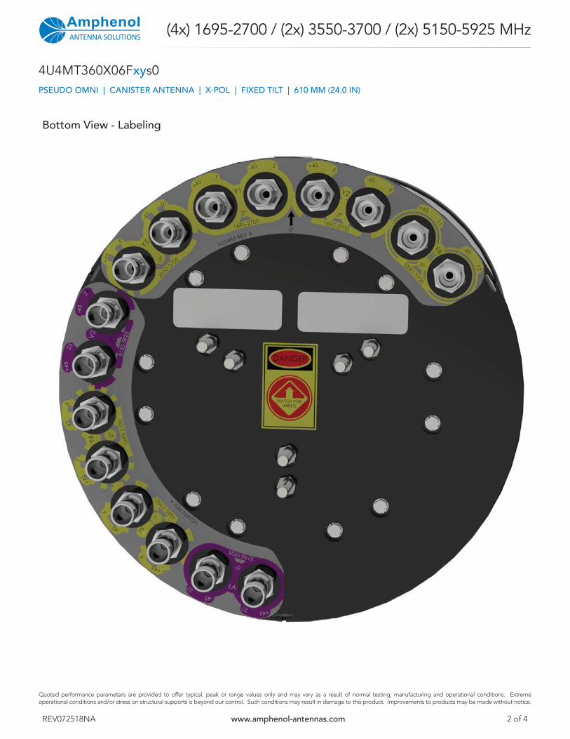
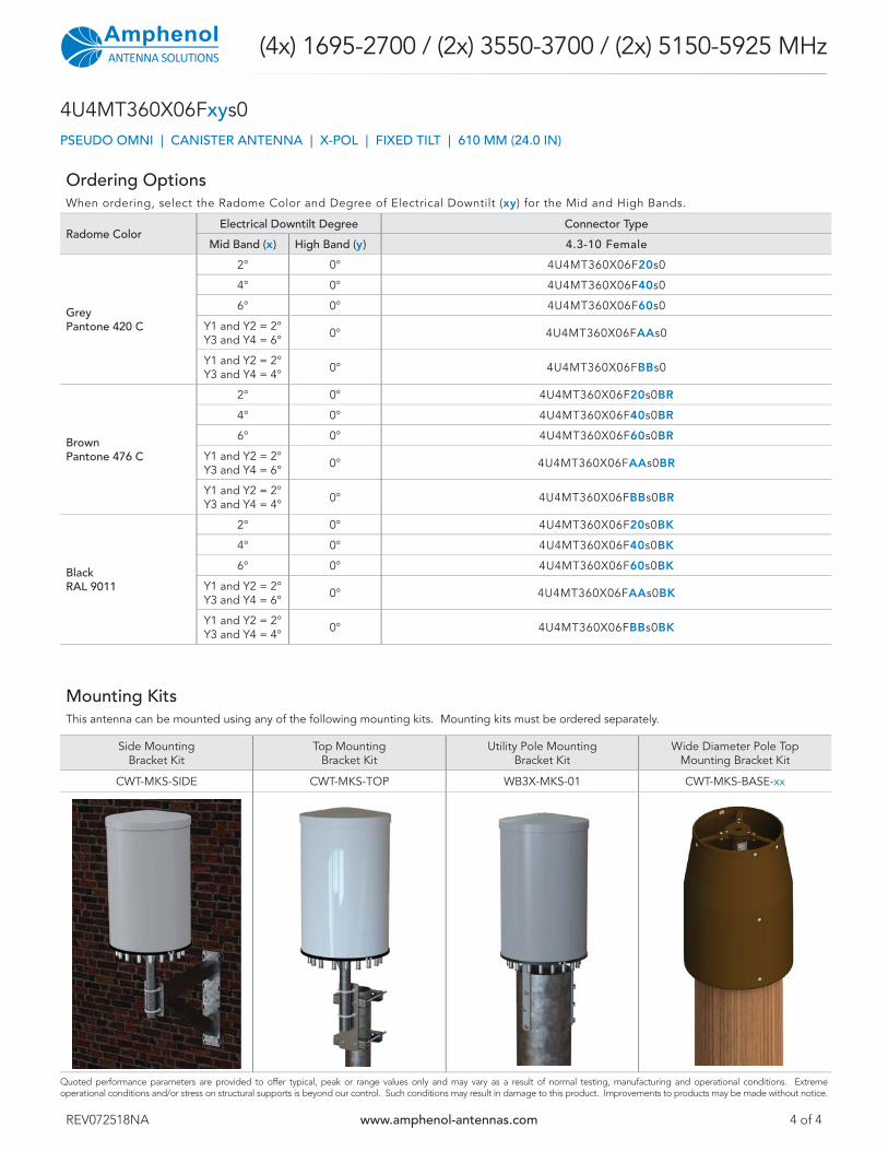
Ordering OptionsWhen ordering, select the Radome Color and Degree of Electrical Downtilt (xy) for the Mid and High Bands.
Radome ColorElectrical Downtilt Degree Connector Type
Mid Band (x) High Band (y) 4.3-10 Female
GreyPantone 420 C
2° 0° 4U4MT360X06F20s0
4° 0° 4U4MT360X06F40s0
6° 0° 4U4MT360X06F60s0
Y1 and Y2 = 2°Y3 and Y4 = 6° 0° 4U4MT360X06FAAs0
Y1 and Y2 = 2°Y3 and Y4 = 4° 0° 4U4MT360X06FBBs0
BrownPantone 476 C
2° 0° 4U4MT360X06F20s0BR
4° 0° 4U4MT360X06F40s0BR
6° 0° 4U4MT360X06F60s0BR
Y1 and Y2 = 2°Y3 and Y4 = 6° 0° 4U4MT360X06FAAs0BR
Y1 and Y2 = 2°Y3 and Y4 = 4° 0° 4U4MT360X06FBBs0BR
BlackRAL 9011
2° 0° 4U4MT360X06F20s0BK
4° 0° 4U4MT360X06F40s0BK
6° 0° 4U4MT360X06F60s0BK
Y1 and Y2 = 2°Y3 and Y4 = 6° 0° 4U4MT360X06FAAs0BK
Y1 and Y2 = 2°Y3 and Y4 = 4° 0° 4U4MT360X06FBBs0BK
PSEUDO OMNI | CANISTER ANTENNA | X-POL | FIXED TILT | 610 MM (24.0 IN)
(4x) 1695-2700 / (2x) 3550-3700 / (2x) 5150-5925 MHz
Mounting KitsThis antenna can be mounted using any of the following mounting kits. Mounting kits must be ordered separately.
Side Mounting Bracket Kit
Top Mounting Bracket Kit
Utility Pole Mounting Bracket Kit
Wide Diameter Pole Top Mounting Bracket Kit
CWT-MKS-SIDE CWT-MKS-TOP WB3X-MKS-01 CWT-MKS-BASE-xx

ATTACHMENT 2

ATTACHMENT 3
General Power Density
Site Name: LIME ROCK PARK SC 1 CTCumulative Power Density
OperatorOperating
Frequency
Number
of Trans.
ERP Per
Trans.
Total
ERP
Distance to
Target
Calculated
Power
Density
Maximum
Permissible
Exposure*
Fraction
of MPE
(MHz) (watts) (watts) (feet) (mW/cm^2) (mW/cm^2) (%)
5G 28GHz 28000 0 0 0 24.3 0.0000 1.0 0.00%VZW CBRS 3600 0 0 0 24.3 0.0000 1.0 0.00%VZW PCS 1970 1 510 510 24.3 0.3106 1.0 31.06%
VZW Cellular LTE 869 0 0 0 24.3 0.0000 0.579333333 0.00%VZW Cellular 869 0 0 0 24.3 0.0000 0.579333333 0.00%VZW AWS 2145 1 510.00 510 24.3 0.3106 1.0 31.06%VZW 700 746 0 0 0 24.3 0.0000 0.497333333 0.00%
Total Percentage of Maximum Permissible Exposure 62.12%
*Guidelines adopted by the FCC on August 1, 1996, 47 CFR Section 1.13101 based on NCRP Report 86, 1986 and generally on ANSI/IEEE C95.1-1992
MHz = MegahertzmW/cm^2 = milliwatts per square centimeterERP = Effective Radiated Power
Absolute worst case maximum values used, including the following assumptions: 1. closest accessible point is distance from antenna to base of pole; 2. continuous transmission from all available channels at full power for indefinite time period; and, 3. all RF energy is assumed to be directed solely to the base of the pole.
Page 1

General Power Density
Site Name: LIME ROCK PARK SC 2 CTCumulative Power Density
OperatorOperating
Frequency
Number
of Trans.
ERP Per
Trans.
Total
ERP
Distance to
Target
Calculated
Power
Density
Maximum
Permissible
Exposure*
Fraction
of MPE
(MHz) (watts) (watts) (feet) (mW/cm^2) (mW/cm^2) (%)
5G 28GHz 28000 0 0 0 29 0.0000 1.0 0.00%VZW CBRS 3600 0 0 0 29 0.0000 1.0 0.00%VZW PCS 1970 1 510 510 29 0.2181 1.0 21.81%
VZW Cellular LTE 869 0 0 0 29 0.0000 0.579333333 0.00%VZW Cellular 869 0 0 0 29 0.0000 0.579333333 0.00%VZW AWS 2145 1 510.00 510 29 0.2181 1.0 21.81%VZW 700 746 0 0 0 29 0.0000 0.497333333 0.00%
Total Percentage of Maximum Permissible Exposure 43.62%
*Guidelines adopted by the FCC on August 1, 1996, 47 CFR Section 1.13101 based on NCRP Report 86, 1986 and generally on ANSI/IEEE C95.1-1992
MHz = MegahertzmW/cm^2 = milliwatts per square centimeterERP = Effective Radiated Power
Absolute worst case maximum values used, including the following assumptions: 1. closest accessible point is distance from antenna to base of pole; 2. continuous transmission from all available channels at full power for indefinite time period; and, 3. all RF energy is assumed to be directed solely to the base of the pole.
Page 1