motor mp8 mack 2
TRANSCRIPT
REPAIR INSTRUCTIONS, PART 1
1. Assémb e lhe slii'ener plalewilh ñN lasl6n€c. Do NOT
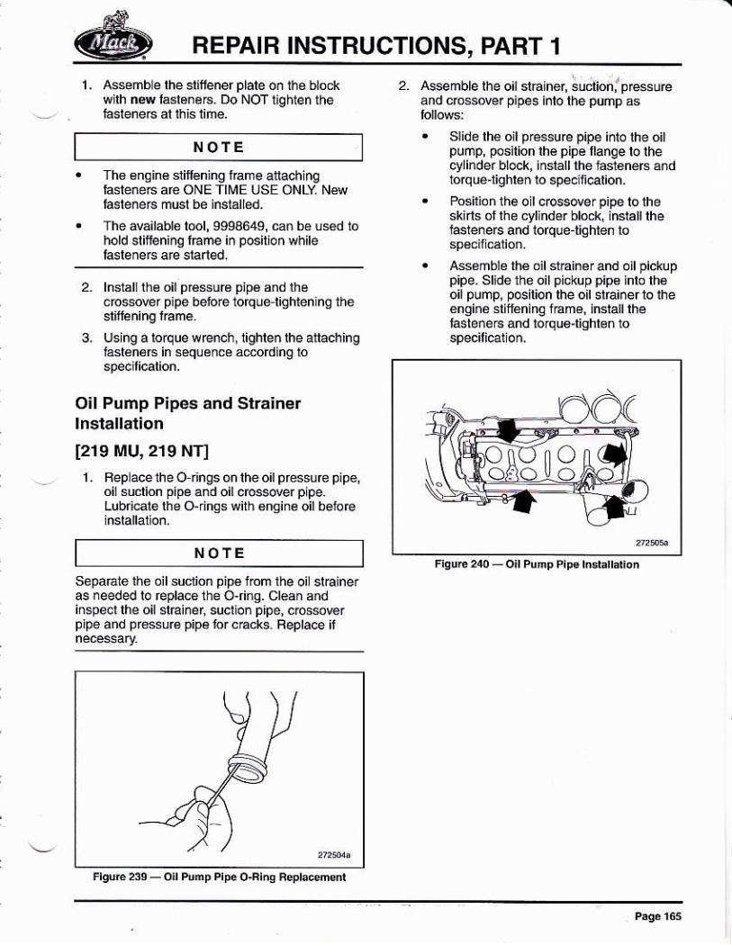
2. Asemblelhe oi¡ siáher, ;udioni pEs6u@8nd ccsové¡ pipes inlo lhe púñp as
slide thé oil pessure pipe inlo lhe oitpunp, posilion lhé pipé llanqe lo lhect4inder block, ¡nslall the lasténéfs andtorqué'lighren to 6pe6ili@tion.
Posilion lhe o I ccsder p¡pe lo ihesklrls óf lhe cyllnder blo¿*, lnstall thehsteneE and lorqüetighten to
¡6s¿mblé lhé otl slrainér and oil pickuppipe- Slidé the oil pickup pip€ inlo lh€oil pump, posirion rhe oil srfa¡ner ro iheén9in6 stif€ning fÉmé, insrall rheIasteñéE and bJqué'lighlen lo
oooo
NO'Efh6 6ngin6 siilf€ning fame aíachlnqf4tene6 are ONE TIME USE ONLY N&lasleóers musl be installed.
The aváilable lool, 9994649, cañ ba usd iohold slifening lEme iñ posillon wfile
lnsrallthe oil pfé$uB pipé and lh6cfo$o@r p¡pe bet)€ tofqu+l¡ghtenlng the
Using a lorque w rench, lighle¡ lhe alachingfasl€néB in s€quénc6 amording lo
Oil Pump Pipes and Stráinerlnslallation
[219 MU,219 NT]
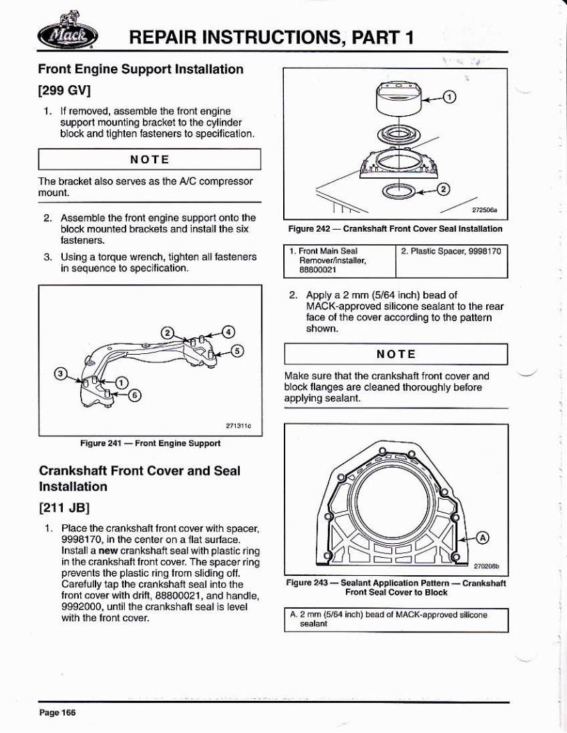
1, Bepacelheo t¡ngsonlheol pressúfe pipé,oi! suclion pipe and oil dosever plpe.Lubricate the O-dngswith 6ngine oilbetoe
NOTE
sépaÉte th¿ oil suclion pipé l¡om !hé oil stEineras needed lo Éplace the o,finq. cléan andiñspect lhe oil stEi¡er, suclion p¡pe, cos$@rprpe and pr6ssuré pipá ror c€cks. Feplace il
FEPAIR INSTBUCTIONS, PART 1
Front Eng¡ne Support lnsta¡lation
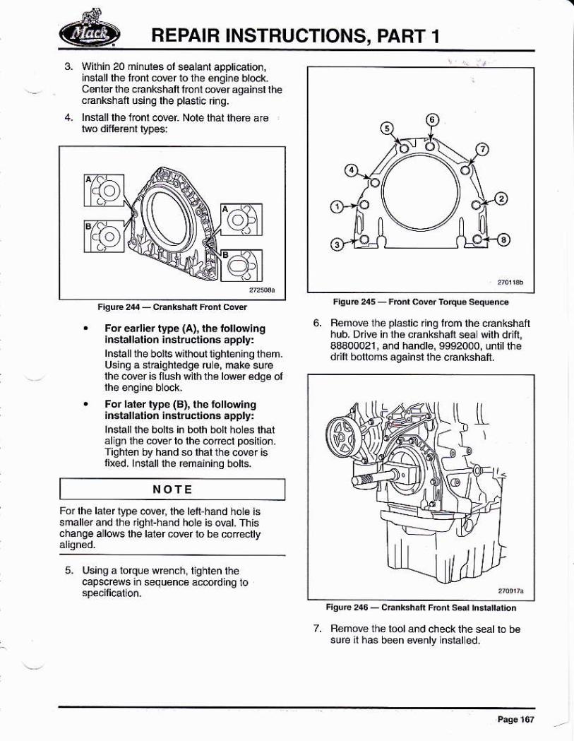
1299 Gvl1- ¡l €m@d, dsenbte the loni enqiñé
suppo mounring bfaokel ro rhe qlindefblock and lishleñ hsleneB lo specili€llo¡.
NOTE
Tho bdckél also setu4 as lhe ¡/C @ñpre$or
2. Assemble lhe lon¡ engine suppo.! onlo lhebl@k moudád bBckéts a¡d iñslaLlthé sit
3. Using a lolque wénch, tghle¡ all lasteneAiñ sequen@ ro sp6ilicarion.
l2 Pr6r. sp*ar stes 170
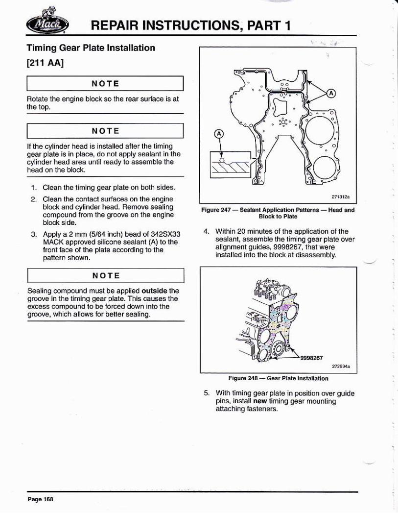
2. Apply á 2 mm (5/g lnch) bead otlvAcK approred sal¡cone seálañl to thé r6arlácé ol lhé der ac@ding to the patern
Crankshatt Front Cover and Seallnstallatlon
[211 JBl1. Pla@ lhe cánkshaft lronl cowr wftn 6pacer.
9998170, in lhe cenler oñ a llal sufface.lnstal a ns cErkshaft seal wllh plasl¡c rlng¡n lhe cánkshalt lrcnt mr The spacer ¡ngprryenls the plás1ic fing lrcm sljding olf'carelully lap the crankshatt seát intó lhelronr co€r with d tl, 68400021 , and handte,9992000, unlii lhe cEnkshaft *d ls le@l
NOTE
Make sure lhai the cÉnksháft lonl @ver andblock tlanges are cleaned thoroughly b6lor6
a 2 mm (re inch) bead o' MAcK¡ppr@3 siticone
REPAIR INSTBUCTIONS, PART 1
3. Within 20 minulés ol sealanl appl¡calion,inslall lhe font wer to the éngine [email protected] cEnkshaf lóñl 6v€r againsl rhec.anksháf usinq lhe pl4lic fiñg.
4. lnrall lhe font @wr Note that the6 a¡€
F.uE245-FE6vdrÓiquós¿qenc8
5. RemoE the plaslic ring fom the crankshanhub. Dn@ in lh6 cÉnkshaft sea wilh dr¡ll,48400021 , and handle, 9992000, unlil lhed ft bónoms against the c€nkshatt.
For éarliéf typé (a), rhe tol¡Nirglnstallal¡on ¡ñstructioñs ápply:lnsla ll Ih e bo¡is wiihoui 1¡ghGñh g lh emUsing a stEighrédgé ru e, make surethe cder is flush wilh the leer édaé ol
For lárér rype (B), the iolrowlngirsl¿llát¡on inslructoN apply:lnslallthe bolls in bolh boh ho es lhalal gn lhé cove¡ lo lhe @@t posltun.Tiohtén by hand so lhállhe cder islúed, lnsiallihe remaininq bo[s.
NOTE
For lho laler lvpé @ver, the tef hand hol€ issmallerand lhe righr-hánd hole is ovat. Thtschange a lows the laler mrer io bé coreclly
5. Us¡ng a torque wén.h lighlen thecapscrews iñ sequonc6á@dinq lo
BEPAIB INSTRUCTIONS, PART 1
NOTE
NOfE
Tim¡ñg Gear Plate lnstallation
1211 AAI
Roiale the engine b ock so the rear sur'a@ is al
fthe cyr¡nder head is lnsralled atrer lhe riminqgeaf plale i6 in pla@, do nol apply séáhfn in lhecylinder h€ad ár€a uniil Éády lo as*mble lhe
4. with¡¡ 20 ñinutes ol ihe appli€iion ot lhesealanl¡ assemblelhel¡ming gear p¡aie orer¿lianm€nl quides, 9998267, lhal weelnsialied lnlo lhe bloók at disassembly.
1. Clean lhe limino qear plale on bolh sidés.
3.
Clean lhé @ñlacl sulácés on lh€ €nqineblockánd cylinde¡heád. Bém@ealingcompolnd fom rhe grcoE on rhe englne
Apply a 2 mm 6/e inch) bead ol 342SX33MACK appr@d sili@ne sealanl (A) lo lhelronl laÉ of lhé plal€ adording lo lhé
Sealióg @mpound musl be applied ours¡de theaoM in lhe limino oáá¡ plalé. This causés lhéexcess @npound lo be iofced down lffo thesb@, whicn a[@5 b¡ betersalinq.
NOTE
5. Wilhliming gear p ate iñ posilion @rguidepins. inslall n4 liminq qea. mounl¡no
REPAIR INSTRUCTIONS, PART 1
NOfE
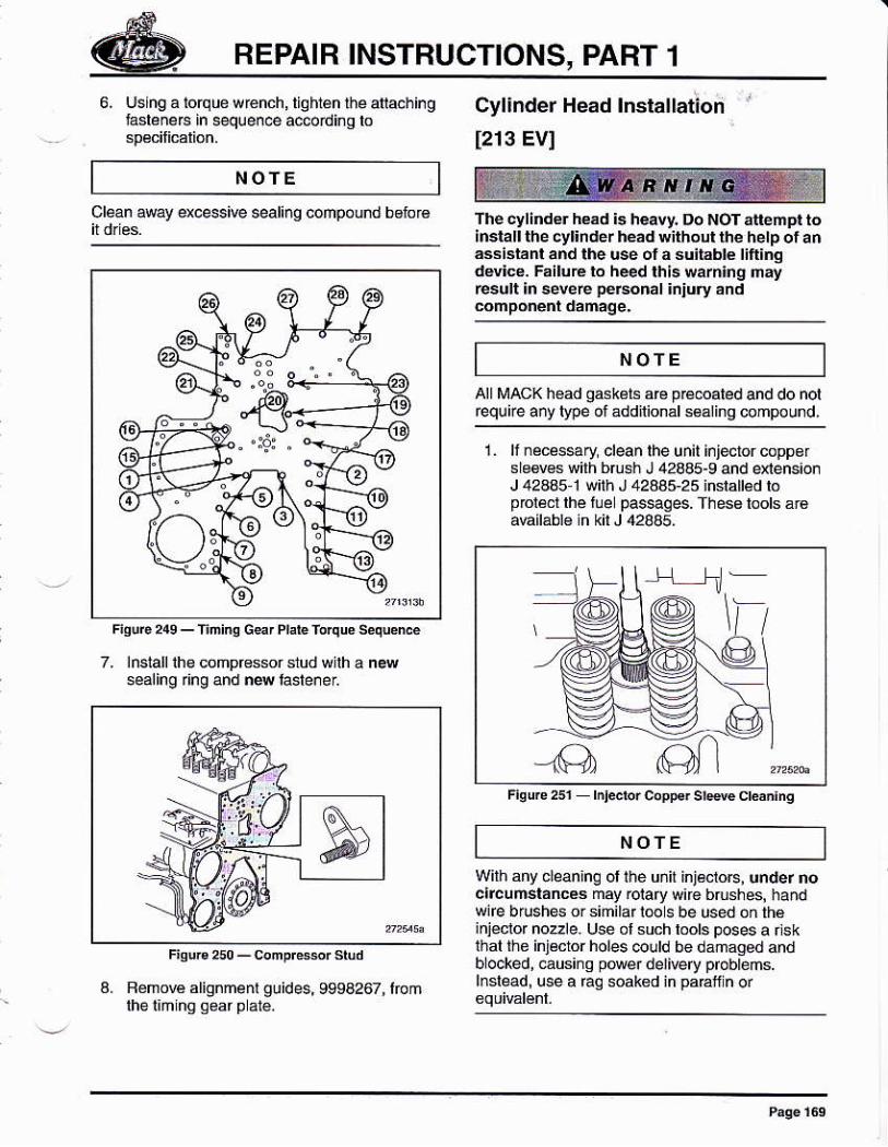
6. Uslng a iorque wénch, tighián lhé afia.hinglasléneF in sequen@ ace¡di¡g lo
Cyl¡nder Head lnslallation
[213 EVI
The cylind€r h€ad b heavy. Do NOT alléñpl to¡mtatt lñe cyt¡ndér héád wiihout the hetp ot aráasisiánt and lhe us ol a suit¿blé ¡ifi¡nqdd¡@. FsiluEto h*d thls warnlng mayr6ult ln sevée personal ¡ñjury ánd
all lr¡acK héad g*k¿ts arc pÉ@ated and do notequire añy lypé ot áddnional s6¿ling compound,
Wilh any cleaninc ol lhé unit iniéctoB, u¡der noc¡tcuñsláncea may @lary wúe brushes¡ handwife brushés orsimilarl@s be used óñ th€inieclor nozle. Usé ol such rools poses a ns kthal the inj¿clor holes @uld be &maged andb ocked, eusinq p@er delivery probrems.lnslead, use a Éq soak€d ¡n páEf n or
Cl@n away excessive sealing compóund betoré
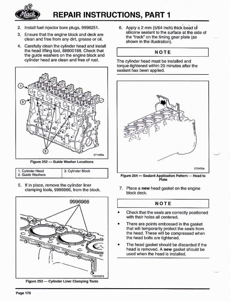
7. lnslall the compressr slud wnh a newsealing ring and n4lasle¡el
a. Rémore alignment guides, 9994267, Ióm
NOTE
1. lrnéc¿ssary clean lhe unit injetorcoppersle6v€s wilh brush J 428a5-9 and extens¡onJ 42445 1 w¡th J 42445-2 5 :nslalled lopfolécr lhe fue paseges. fhess bols á16aúilábl€ in kil J 4245.
NOTE
Fieure 2sr hj*br c¡pFr srp{e cr¿án¡nq
REPAIR INSTRUCTIONS, PABT 1
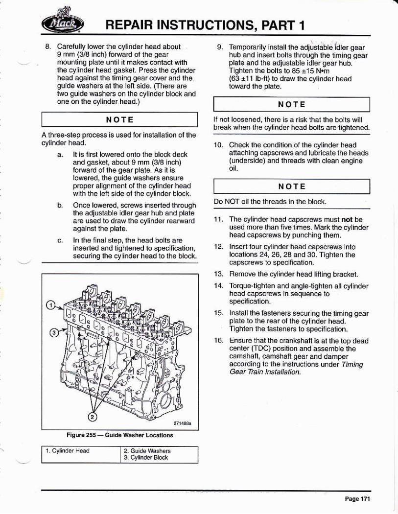
2. lnsiall fuél lnlector boé plúqs, 9994251 .
Ensuro thal ths €ngin€ block ánd dtrk ar€clean and iree lom any dirt, qfeae or ol.Caelú¡ly ¿léáñ rhe cylindd head and indallthe head lifting tool a3a001aa. ched< thatihe guide washeF on lhe e¡qine bl@k andcyli.de. head aE clean and lree or rusi.
6, App y a 2 mm (164 ¡nch) lh¡ck bead cilsilimn6 s6álánl 10 üe sudace at tho s¡de olthé 1ácr ón thé liminq géar plate {assh@n in lhe illuslalioñ).
ffi*fl3fi
NOTE
Tlre cylinder nead musl beioq ue-liq hrened wilhin 20sealanl hs be6n app i€d.
FiguB254_€e¡l¿nlApplldl.nh¡MH¿adb
5. ll in Place, éñde thé cy ind€rclañping lools, 9s96966, Iom a ns head gaskel on lhe enq¡ne
9996966
FlquE253_cy[ddln¿rcl,mplnqTml3
NOIECheck that lh€ seals are coreotly pos¡l¡onedwilh lheir ho¡es all €ñt¿Bd.There are pohls embo$ed in lhe qasketlhal will lempoErfy polect th6 s€als iómthé h€ad. Th66e wi I be @mpÉss€d wheñthe head bolls a.€ lighlened.
The héád gásk€l should be dlscaded ilthehead is Emoved. A nN sasker should beu6ed whén rhé héád is lñ$ánéd
REPAIB INSTRUCTIONS, PABT 1
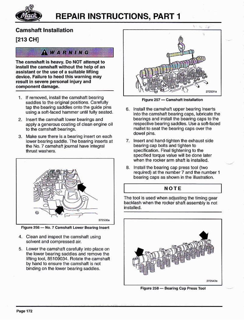
a. Caelllly lowerñ€ cylndér hsd aboulI mm (3ts inch) lotuad ol thé qéármou¡ling plale unlilil makes co¡lácl wilhthe cylind€r h€ad gaskel. Pfe$ lhe cyllnderhead againl lhe liniñg g6ar corer and lheguide washeB ar rhe efi side. (Ih€f€ a€lwo guide w$he6 or lhe ctlinder block andon6 on lhé cylinder head.)
ll is li6l l@e@d onro lhe bl@k dekand qásket, about I ñm (3/3 hch)bNad oi rhe geaf plare. A5 ¡r isIowered,lhe quide washeB ensu¡epópd alignñé¡l ol lhe cyliñdér héadwirh rhe bn slde ol the cyl¡ndef block.
O¡ce lweed, screG i¡serled lhouqhthé adiustáblé idlér qéar hub ánd plaléa€ used io draw lhe cyliñder Éafrard
ln lh6lnalsláp,lhe head bot6 areinserted and tighlgn€d lo sp€cllicalion,securinq lhe cy ¡rdef head io ihe block.
L TeñpoÉrry rnsrall rhe adjosrablo idr€r q€arhub a¡d lnsért bolr€ lhrough the lim¡ng qearplare and rhe adjlstábra idre. gear hub.Tighléñ lhé bolts b a5 +15 N.m(63 i11 lb-ñ) lo dÉw the 6ytlnder head
NOTE
ÑOTEh@d botts aÉ tightened.
A th@-slep prcce$ is used tor inslallalion ol lhe10. Check the úndilion of lhé cfinder head
anachi¡g €pscf4s and lub¡l€te the heads(undé6idé) añd rh€áds with crean engine
NOTE
ffi11, The cylinder head cap*rews ñust ñot bé
used ñ016 lhan fi@ times. Mark the cylinderhead @pscBm by punchi¡g lhem,
12. lnsert lour cy indér h€ad capsc€ws lntol@alions 24, 26, 2a a¡d 30. Tighlen lhempsc@ws to specil¡cation.
13. Remo€ lhé cylinde r head llfr ing b racksl.
14. Torque-lighlen a nd angtet¡ghten att cyt ñdé Ihead cap*rews ñ s¿quén.e io
Dó NoT o r rhé rhreáds in thé hr6rr<
lnslal lhe lasle¡e 6 secur ñg lhé liminq gearp á16 to thá rear oi lhe cyl nder h€ad.¡ghleñ lhs lásle¡eF to specifcal¡on.
Ensure that lhé c€nkshalt is át th6 lop d€adcenre¡ (Toc) posilion and 4sembe thecamshalli camshail géar ánd dámperác6rdi¡q ro ihé inslrucl ons und€r Itnt4g
15.
REPAIR INSTRUCTIONS, PABT 1
Camshatt lnstallation
1213 CHI
Thé cáñ3hált ¡s h4vy. Do NoT álléñpl to¡nsláll lhé cañsh¿ll wilhórd thé hélp ol arássistant or thé use ol a sulable fltingde!¡ce. Falture to heed thls war¡¡ng máyresut ¡n severe peBon.l injury ánd
2,
3,
6,
3,
lnslalllhe camshai uppe¡ b€aring insedsiñto lhé.ánshafr bea ñg caps, ¡úbricále thébeannls añd l¡siall lhe beariñg caps lo lherespeclive bea¡ing saddles. Use a soflacedmallet tó séal thó b6áriñg €ps d$ th6
lnsen and hand i¡gh1en lhe dhaust sldebeari¡g cap bolts and lighien lospd¡licalion. Fjnal liohl€nina lo lh€speil¡ed lofque %lue wlll be done lalerwhen rhe rccker arm shafi is insralled.
¡¡stallrhe bearing ep p¡ess i@r (1wor€qukád) al lh¿ numbér7ánd lhe number 1
bea ñq €ps ás sh@n in lh8 illuslÉlion.
fhe lootis used when adlústing thétimtng g€arbacklash when lhe ocker shafi assembly is ¡ot
NOTE
ll rcmov6d, iñslaLlthe canshati bear¡ngsaddlesiolhe odginal posilions. Ca€lullylap lhe bea ng saddles onlo th e guide pinsusing a soit-la.€d haññé¡ until lully sealed.
lnsenlh6 €mshafi low6r bearings andappry aceñefous c@1n9 ol clean engine oillo lhe camshaí béarlngs.
Make suré lhe¡€ b a b¿áing insrt on eachlowér beárlng saddle. The beaf¡ng insefls ailhe No. 7 camshat jouhal haw lnlégEl
4. C ean and inspect the canshalt usinqsolwnl and comp@sed a¡r
5 Lower ihe camshafl caretully into place onlhe lower bearlnq edd es and €move lhelifiing lool, 45109034. Folalé lhe camshaftbY hand io énsure tho emshaft is nolb¡¡ding on the l@er beár¡no saddlés.
REPAIR INSTRUCTIONS, PART 1
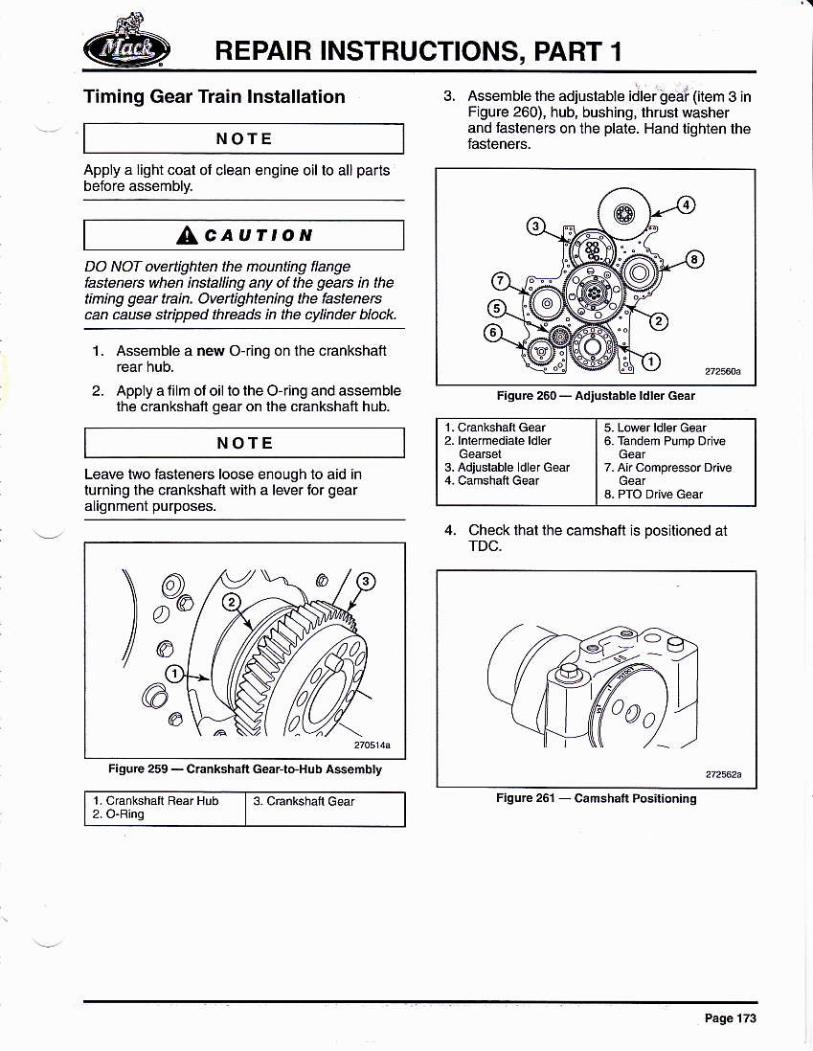
Timinq Gear Train lnstallatlon
NOfEApply á liQhr coal ol clean engine oil lo all pa¡ts
^caurroNDO NOI ovdlightú thé Mlkg awélastenets when instalkg añy ol the géaÉ ln thet¡n¡ng qeat tak. oveñjgl,ten¡ng the hstaetsan @M sriwad fh@ds i¡ lhé ct4indd blúk.
FisuE e - adlus* rd!¿r &ár
3. Assembb rhé adiusrábré i¿b; b@loem 3 inFigurc 260), hub, bushins, lhrusl washerand laslereG o¡ the plate. Hand llohi€n lhé
t6 ráñden Puñr Df 6I Gd,
3.adjGbbre dsGs | 7.Af hec<f D,ñe
1. As*ñbl6 á r4 o dnq on lhe chnkshafr
2. Apply a l¡lm ol ol io lhe O ring and ssemblelhé chnksháí gáar on lh€ c€nkshal hub.
NOTE
Leaw two fáléneÉ lo6eluming lhe cEnkshatl wilh
FiguÉ259_cEnk3hliGsrlaHubtrséñbly
4, Chéck l¡al lhe @mshatl is posilioned at
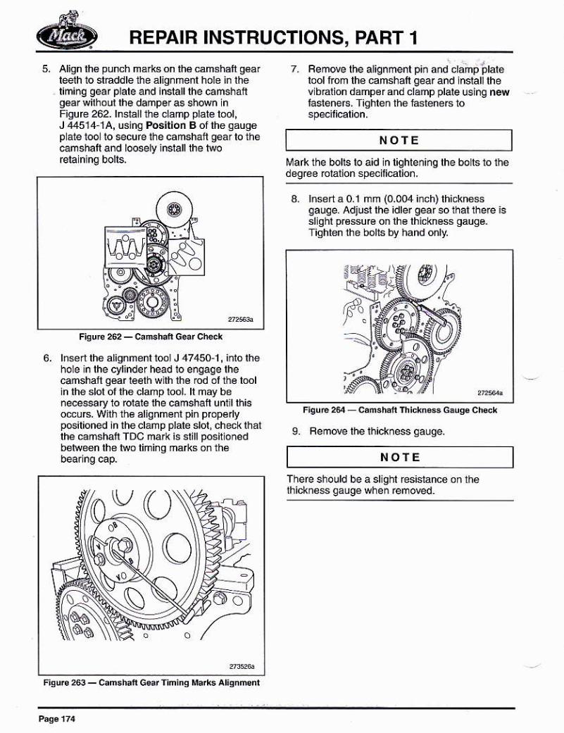
REPAIB INSTRUCTIONS, PART 1
Align lh€ punch márks on lhá camshaft géa¡leeth 10 sláddle the al¡gnmenl hole in lheriming geaf plare and inrallrhe camshangear wirhoú lhe d peras shan nFigur€ 262- lnslall 1ie clamp plate lool,J 4451,1-1?\, using f¡ositior B of th6 gaugép ate 1oo lo scufe the camshait geá¡ to theúmshalr and loosely inrall the rwo
6. lnsed the alignmenl lool J 47,150.1, iñió lhehole in lhe cyl¡nde r hed 10 engaq e lhecúshatl gear ¡eelh w lh lhe ód ol l¡e loolin the slol of the clamp tool- ll may benecessafy to forare rhe camshafr unul rhisomuB. Wilh lh6 alignménl pin prcpé yp6ilioned ¡n theclanp plale sloi, checkihatlhe camshail TDC mark is sl¡ll po6ilionedbo¡reen lh€ lwo limi¡g mafts on lh6
7 Femove lhe aliqnmenl pln ¿nd cl¿mpplarelool from rhé camshatr gear and lnsrall rhev bdl¡on dampgrand clamp plale using n4lasleners- T¡ghlén thé lastenec io
Mafk the bolrs ro aid ln righrening rhe borts 10 thédegr¿e rclalion sp&ilicalion.
a. hselta0.1 mm (0.004iñch)thickhessgauqe. Adjur rhe idler geaf so thar thele isslighr pr€ssu€ onlhé lhickn6ss gaugé.Tiqhten ihe bolts bV hand onht
9. Femde lhelhickness qauqe.
NOfE
t'¡oTE
F¡4uÉ263_can.h¡fG.¡l'in¡iqlla*s^liqnmnl
a sllghl resislance on th6
REPAIR INSTRUCTIONS, PABT 1
'V66
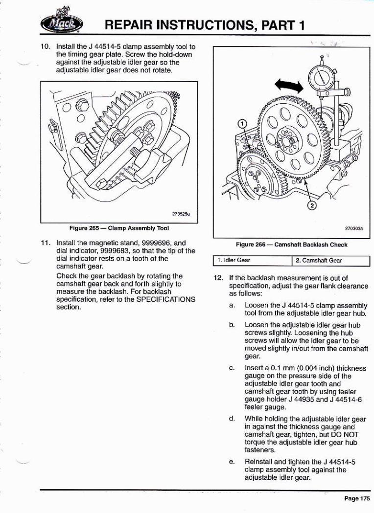
10. lnslall the J ,1451,1,5 clamp asémbly tool 10thé timang oear plate- S6re the hotd-downasainsl ¡¡a adjusrab e idler gear s theadluslablé idl6r q6a¡ doés nol rctaie.
11. lnsrallrhá maqnálic sránd, 9999696, anddlal i¡dl€tor, 9999643, $ that lhe 1ip ol th¿dial irdi€lor resls o¡ a 1@th ol thé
Ched< the qear bacJilash by rotalinq lhe@mshati g€r back and torrh s iChtly romeasuÉ lhé backlash. For backlashspecilicatton, éler to ihe SPEctFtcATtoNS
12- ll thé backldh measurement is olt olspecif@lion, adjust th6 s€ár llank cleaBnce
Loós¿n lhe J 44514 5 ddp ássémblyiool rrom rhé ádjustable ldrer gear hub.
Loossn r¡¿ adjustab e ¡d¡er Oear hub$r4s slighlly. LoGening the hubsc@s w¡llalúihé idlérqearlo bemov€d slighlly irvoui nom lh€ ám6haÍ
¡nsert a 0.1 mm (0.0er inch) thicknésegauge on lhe prássue side ol theadjusrable ld er qéár toolh andcañshafl qear loolh by using l€álergauge hóldér J 44935 a¡d J ,t4514,6
Wh ile holdino th€ adjuslable ld le r gearin aoa nsl the th¡ckne$ qauoe and€ñshaft géar,liqhlen, but DO NOTlorque lhé adjuslablé idler ged hub
Fein6lall and tiqhien th6 J 44514-5c 5mp a$embly tool against the
REPAIR INSTRUCTIONS, PART 1
I Remove thé leeler gáuq€ from lhéadjustabe dler gear and camshán
g. Fecheck lhe backl4h, Wilh lhespécilied b@klashallained¡ repla@6ach adiuslablé idlér aear hub M.ewwith ns and lighlen the scrows tospe¡licarion one ar a rime so rheanained backlash is nol d¡slurbed.
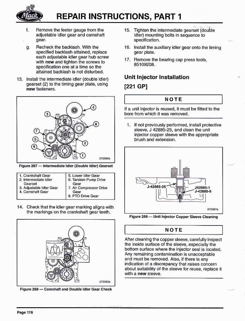
13. rnsiarlthe inrermediare idle¡ (double idLer)gearsel (2) to lhe timing gear plare, us nq
15, Tiqhten lhe inlemediale seá6ál (doutléid ér) mounl¡ng bo¡ls in seque.ce to
16. lnslalllheauxiliaryidlergearonlothétiñino
17. Bemovelhobea og cap pre$ tools,45109204.
Unit lnjector lnstallation
1221 GPI
FisuE 2t rnkrdúr. ¡dr$ (eude rdre4 G¿'rd
NOfE€used, il musl be lited lo lhe
| 6 r eñtumpDre
14. Checklhalnté idlér gearmarking allg¡s withthe markinqs on the crankshafi oeár leelh.
1. f not pr* ously pericrñed, insla I prol€clivesleeve, J 42435-25, a¡d clean the unllinjeclor mppér dé4é wilh lhe app@priale
Afér cleaning lhe @pper deM, carelully inspe.tthe inside sulace ollhe sleeve, espécs ly lhébonom sulace wh6ré lhe injeotor seat is ocaled.Any ¡emainir g contaminalion is u na.ce olabteand musl bé removed. Also, if lher6 is anyindicaton ol a discrepancy lhal ra¡ses concehaboul súlabilityoflhe sleere lor réuse, repta@ il
NOTE
irFrquc te uñn hEdor coo@r sreeve creaninq
FEPAIR INSTRUCTIONS, PART 1
3.
FiquÉ 270 - Unft rn¡dor Borc PEr€dion sre#
Betore Busing añ i.jector, cle inq jsrsquiréd to €nsure suilability tor éuse.Berc're doing ar'y c éaning, rhe injelor tuelinlel and oullel ports ánd lh6 el€cricalconnec¡or opening musl be covered loprdé¡l dnlminarion lrom lhe cl4ningpfo@ss- Also, lh€ré musl be no Lower o{ing¡¡sialled ¡n lhe lnlecior Relérto'uNlTINJEoToF oLEANING'on pag6 244 lor
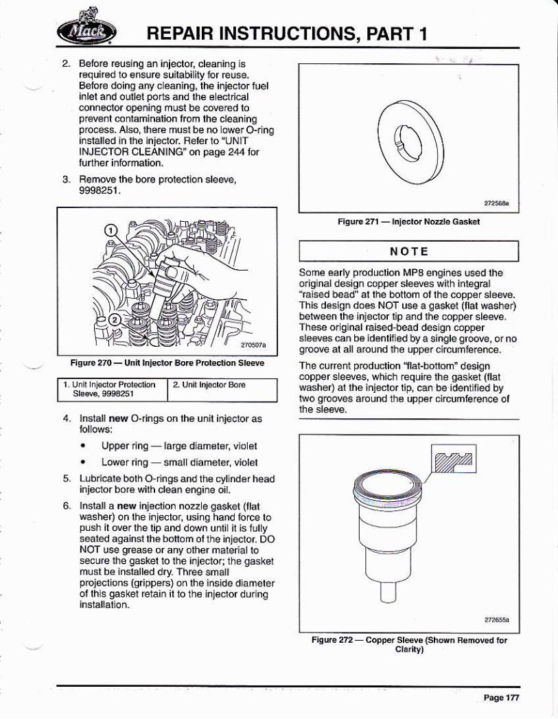
Ren@ lhe boe proieolion deM,9S94251.
1 uni¡ lnlsdo' Prcrdion lr.'rnirlnlebeE
4. lnlallñ6w O{ings on lhe unil injecloras
. Upper nnS larSé dlamelor, viol¿l
. Lower ring smalldlañ6i6r, violál
5. Lubr¡€¡e boih Ojlngs and fis cyl nd¿r headinj¿cror boré wilh clean eng¡ne o¡1.
hstarr a ñe inieclio¡ noz e gaskel {italwasher) on the i¡jéclor, usinq hand lorce topush il @. lhe l¡p and down uñii it is fullyseated againsr lhé bofiom ot the injecror DoNOT use géas6 or any olher nale a¡ losecure lhe gaskel to lhe ¡¡jetor the gskérñust bé inslalled dry Three sñalpojections (srippé6) on rhe inside dlamelerot lhis gaskel rctaiñ il to ih€ injéclor during
FsuE 21 - hFdor Nde G*H
ÑOTE
Somé ea y pbduclion MP3 engines ced lheorjginal design copp€r déms with iniegEllaised bead ar rhe bonom or rhe copper sr66vé.rhis désign doés NOT use a gaskel llat washeDbetween lhe ¡njecior tip 5nd the @pper slewe,These oriqinal Eised¡ead d6lon copD6rsledescan b€ idénrir ed by a single groo@, ornogbove al all around ih8 upp¿r circumie¡ence,
The curent prod uclion 'flal-botom' design@pper sle4esi wh¡ch reqúi€ me gask€t (llatsásher) ár lhé iniécrór rip¡ can be identmed bylwo groov€ áround th¿ uppér circunle¡en@ ol
F¡sur€2 copF. srd. tshwn ¡snmd ror
0
BEPAIB INSTBUCTIONS, PABT 1
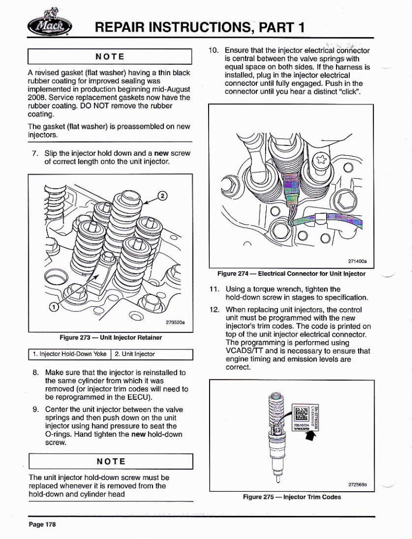
7, SLip lhe injécior hold d@n and á n4 srewof cor€ct l6ñoth oñlo lhe lnll ¡nieolol
Fiore2n-Unft ¡nidorRd¡iner
1 nltuf Nod DM %k I 2 udrhFdr
A rwied g4kel (llal washeo havinq a lhln blac(rubber maling for impMd séaling wasimplemenled ln pbductlon begln¡lng ñld-auqusl2003. Serul.e replacement qaskels n@ have iherubber coaling, DO NOT remove lhe rubber
The qaskel (llal washer) is p€assembled on new
Make sue that lhe inletor ts einstatted lolhé same cylinderfom which il Msreñóred (or inieclor lrim óds will need lobe rep@gEmmed h ihe EEcu).
Cenler lhe un¡l ¡njector ben@en tha Elvésp nqs and rhen plsh down on the lnfinj¿clor using hand pre$¡re lo seal lheO rings. Hand lighlén lhé nil hold-down
NOTE10. Ensure rhar thé i¡jdtor érécld€r @nllecbr
is @ntEl betreen thé hh€ springd wilh€qual space on borh sides. ll rhe hañess isinsiállod, pluq in lhé ¡njecior electrical@nnector únlll tully enqag¿d. Push in the@nnec!o. unlil you hear a diliñct'tlicl\¡.
Fioue274-Erd c¡rconn*brbrunnh,¿dór
11. Using á lorqué w€nch, l¡ghlen lhehold dowñ scéw in daqés to speflicarion.
12_ When Éplacjhg lnil ini€clo6, lhe @nlolunil musl be prcqrammed silh lh6 .sinjécro/s ldm @des, The code is plnled onlop olthé unit injector élécl cal.onneotolThe prcgrammi¡O ls péfom€d 6inqvCADSm and is ne@ssary lo ensub lhál8ñqiné limina and emission levels aé
:3:E
Fisure ¿5 - rnjedq frm ed6
9.
Thé unil ini€clor hold-down scra musl beroplac6d when€vér il is rcmMd l.om lhéhold doM áñd cylinder head
NOTE
o
BEPAIR INSTRUCTIONS, PART 1
NOTEyokes on rheir rcspeclive úd€tüáke sufé rhal lhey afe pbpery
Due to the Enginé El&lronic Cónlol Unit(EECU) sell learn¡ng Épábrity, it isnemssary lo es1 ¡eahed EECUPaÉmetórs aftér s¿ruicing someenq¡ne ielaled mmponents. This dlM lheEECU lo leárn the nd @ñpon€ntsbehavioi After sedcinq ¡s coñp ete,pelon lhé "L¿a¡néd Dala Fesef l6ated in
ll rBinstallinq an in¡eclor inlo lhe sanéocatioñ, rcprooámm nq is not Équned.
Rocker Arm Shattand Engine Brakelnstallat¡on
[213 LPI1. Oillhé vál€ yokés and lh¿ camshaÍ lobes
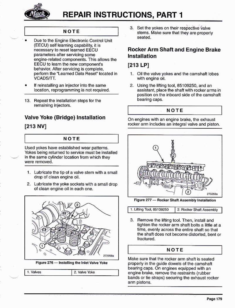
2. Using lhe lilling toot, a5109250, and anGsislanr, placé lhe shall wilh fockef arms inposl¡on on ihe inboard sido ol lhe camshaft
13. Fepear rhe insrallarion sreps tor the
valve Yoke (Br¡dqe) lnstallalion
t213 NVI
NOfE
NOTE
enq¡ne bÉke, ihe exhaustan inleg@ ulve and pisron.
Uséd yokes have éslablishéd wear patterns.Yokes belng returñed 10 seflicé musl bé inslalledin lhe same cylinder ¡ocalion lroñ which they
1 , Lubri€le ihe ilp ol a valve stem wilh a smalldop olc éan éngine oil.
2. LubriBr6 lhe yoké so.*ets with a smatt dropol clean e.glne oil¡n each o¡e.
t, Fódef shar a*mb y
3. Femo@ lhe titling bot. Then, i¡statt andtlghlen lhe mker arm shatt boils á Inb al alime, *dy across lhe enti€ shatt so thallhe shail does nol bmme dislórred bént .r
NOTE
tüake sur€ lhal the rocker arm shan is sealedpfoper¡y ln ihe guide dowels ol the oamsháftbéai¡gcaps. On engines equjpped wilh anongin€ bEké, ¡em@ lhe fesiáinls (rubbefbands oflie slaps) secufi¡g lhe exhaust Mker
IDB
Fsu,€22 Fodersh¿fi a*ñbthdár'dór
REPAIR INSTRUCTIONS, PART 1
NOfE
7. Torqué-lighlgn and anqle-lighlen allcamshaft beadng €p añd óckér an shalbo[6 in sequence a@rdlno 10 spédfcaton.
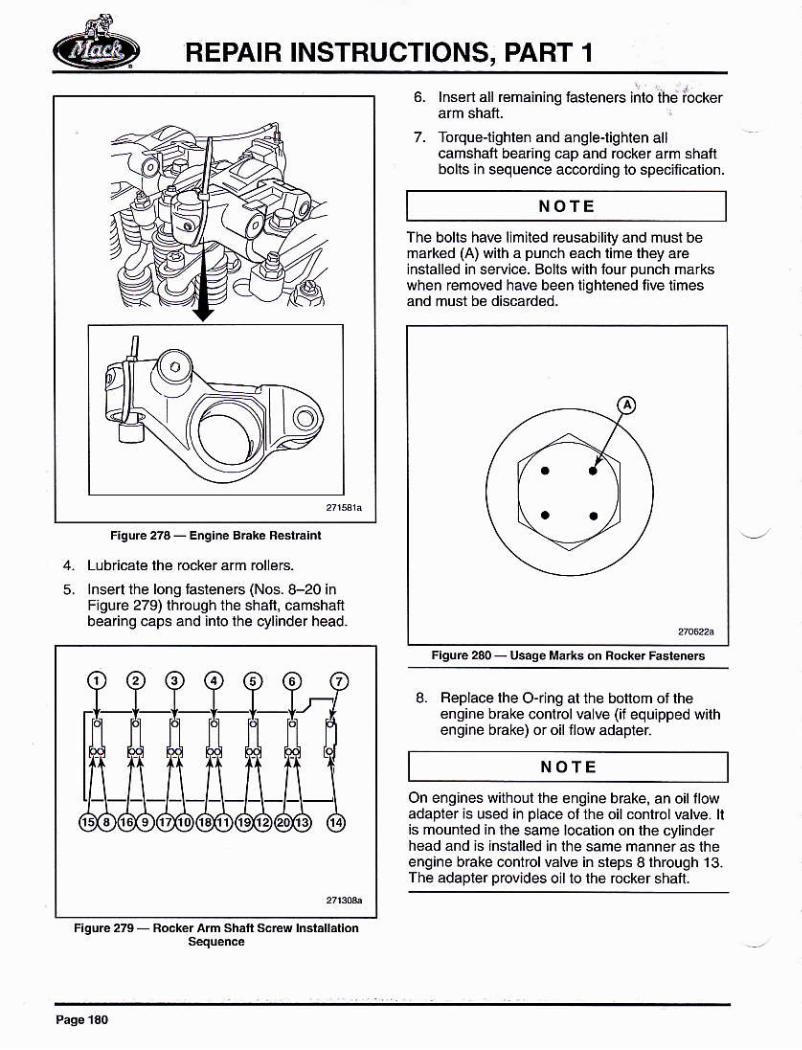
The bohs have llmired reusabrr¡g and must bema¡kéd (A) wilh a punch áách limé lhey aeiñslalled i¡ sedice. Bolls wilh lour punch márkswhen remNd he been lighlened live i¡mes
g. Feplace lhe O{lng al the botlom ot lh€6nsine b@ke conrrcl€@ (¡f equ¡pped w¡rheno¡ne báke) oro now adaDier
On eñgines withoul th¿ engine bEke, an o¡t ltowadapter is used ¡¡ place ol the oil mnl@l valre. ltis mounlád in the eme localioñ on lh€ cytinderhead ánd is installed in lhe same mannerasthéenqine b6ke cofrtrolvdB in sléps S rhrough 13.fhe adapler p@¡des oll to the bckor shaft-
Lub.icalé lhé ó.k€r arm bl é8.lnsen üe bng lasleneG (Nos. 8-20 inF¡gúre 279) lhóuqh the shafl, camshanbearing cap6 and inlo lhe ctlinder head.
5,
NOfE
REPAIR INSTRUCTIONS, PART 1
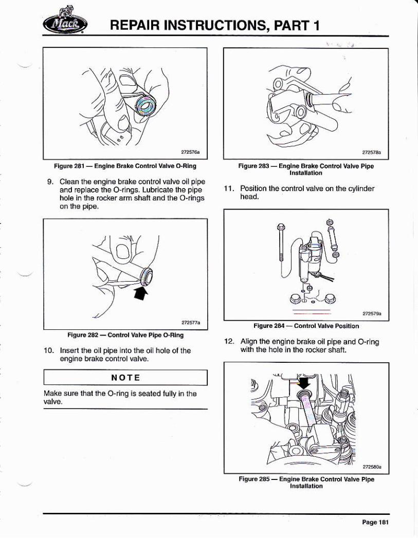
9. Clean ths €nsins brák€ control valÉ oil plpeaód @p ace lhe O-nngs, Lubn@le lhe pipeholá i¡ lhe b.*ér am shaii and lhá Oiings
l0- lnsn ñ6 o lpip€ lnlo lhe oi holeollheengine bÉke cofrtol valre.
NOTE
Mak6 suÉ ihár lhe Ojing is s@ted lully iñ ihe
1 1 . Pos¡tion lhe @ntol válvg on lh€ cylind€r
12. Align lhe englne bÉke oil pipe and Or nqwilh lhé holé in rhé ró.i€r sh.fr
REPAIR INSTBUCTIONS, PART 1
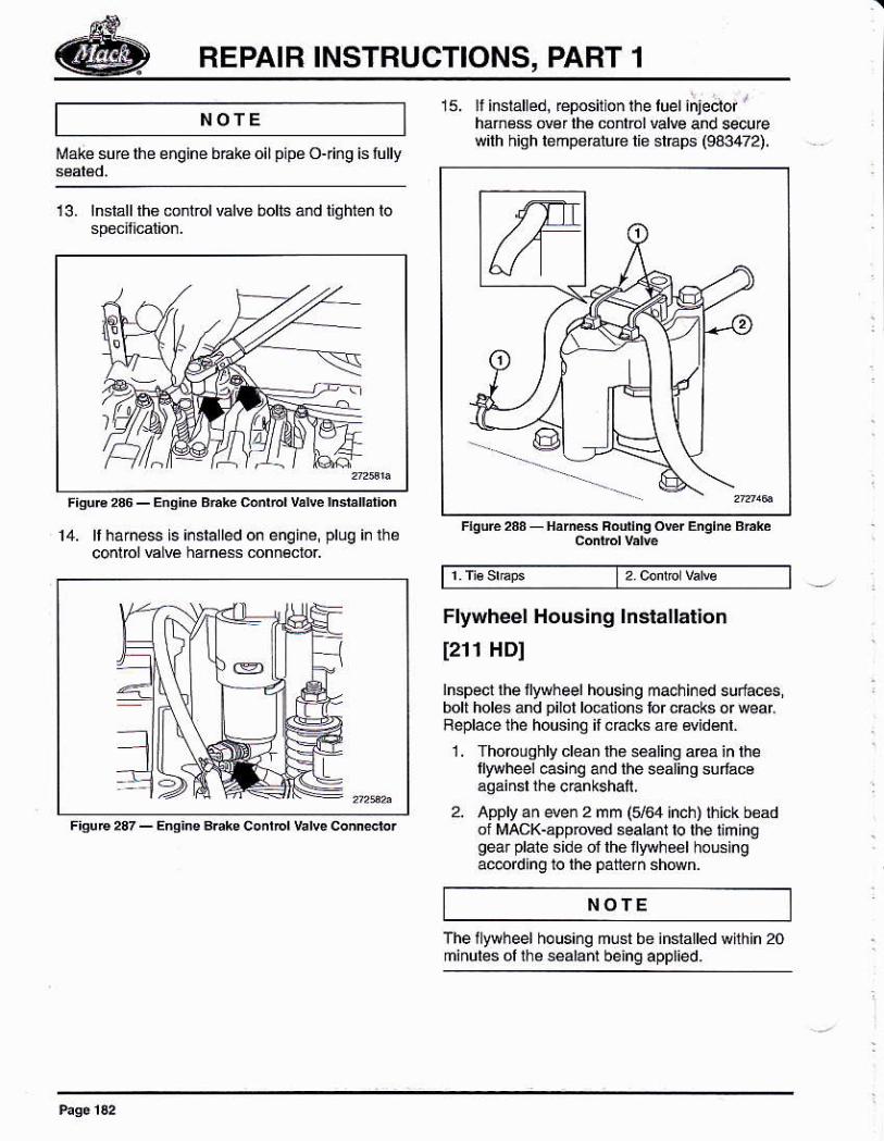
NOTE15. ll inslalled, eposition rhe luel injecior '
hám€ss ov€r lhé conlrol vdre and secureqilh high lehperature tie stráps (943472).
¡¡ak€ surerhe enqine bake oil pipe ojing is lully
13. lnsrállrh6 mnlrolválve bolts añd tighten lo
14. rrharnes isinsralledon enqine, plug irlheconlbl EIE harnéss conn€cror
Flyürheel Housing lnstallat¡on
f211 HDI
lnspecl lhe llyrheel housi¡g ma.hi¡ed suriácesbolt hole! ánd pilot lo€1ions lor cEcks or wear,Feplace the housing il .acks á16 widénl.
1. Thoro! qhly clean tho sealing a€a in lhellywheel €sinq and the sealinq sulácoaqáinsl rhe crankshall,
2. Apply an even 2 mm (164 inch) lhick beadol MAcK-app¡owd sealant to the liminggear plaié side ol the fyrheel holsingac@rding to the patterñ shówn.
NOTE
The llywheel ho using mu st be inslalled whh in 20minules ol lhe sealanl being appl¡ed.
REPAIR INSTRUCTIONS, PART 1
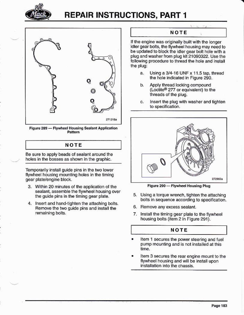
F¡q!rc2s9_Flwt¡élfi.Gi.qs€al,i'Ap.ljolion
NOTE
li ihe enQlne Msorg nally buill wllh lhe ongeridler gear bolts, lhe llyNh€61 housing may need tobé u pdaled lo block l¡re dler qear boll hole w lh aplugandw6herfrcm pluq kii21090322. Uselhefollowinq prccedu ré lo thr€ad lhé hole and nslall
a. Using a 3/4 16 UNF x 11.5 lap, lhroadlhe hol¿ indicáled in Fig!re290,
b. Apply lh€ad locling .ómpound(Loclrle@ 2z or €qu €len1l ro rh€üreads ol lhe p uq,
c. lnÉerr rhe plug wirh washef and tiqhrenro spécilicalion.
5. Using a lolqu¿ wrench, liqhten thé atla¿hinqbolls in sequ€nc€ ac@din g lo specif .a1lon.
Femove any ex€s sealanl.
lnsIalllhe limi¡g gear plate to the iywheethousing bohs (ilem 2 in Figúre 291).
NOfEBe sure lo apply beads oi salanl around theholos in the bo$6s ás sh¡M inthé qEphic,
femporari y irstall glide pins in lhe l$o lowerllyryhee hoLs¡ng mouding holes i¡lhéliminq
3. Wlhin 20 ñinuiés ol lhe application ol lheséalanl, a$emble the tlylvheel h ousinq de rthe quid8 pins ín lh€nminq oéar plale.
4. lnsrl and hánd-t ghlén the á¡aching bolls.Femow the te quide pins áñd inslalt lh€ 6
7.
NOfEllem 1 s€úés lh6 powér sleering and tuetpump mounling and is not insia led al this
h6m 3 smures lhe rear engine mounl lo lhéilyryheel housing and will be instalt upoñi¡slallálion inló thé chassis
REPAIR INSTBUCTIONS, PART 1
AcaurloN|repe.x lhe rcnNét/¡rstalü @elully. At ydatuae ú lhe loal \|¡I d4ttay lhe ffi|.
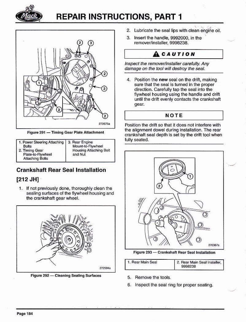
Lubricaté lhe seallips wilh clean engiÁe oil.
lnsenlhe handle, 9992000, in lhef emover/inslaller 9994233.
4. Posilion lhe n4 seal on lhe dn'f, mak ngsufé thal thé séaL !s luméd i¡ rhé pppérdkelióñ. cafelully tap the seal into lhellyohe el housing uslng ihe handle and d ritlunlil lhe dr fi e€nly conlacls th¿ cEnkshalt
2.
3.
NOTE
Crankshatt Rear Seal lnstallation
[212 JH]1. li ¡ol p €viously done, lho rough ly clean lhe
sealinq súlaces ol lhe Íyryheel housing andlhe cÉnkshaf qearwheel.
1 Pore¡ sbs'inq Aturrinq 13. BsarE¡qhsI Mdún, ro Fr!}hel
| ándNú
Position the drift so lhat it does ¡ot iñierleG withrhe alignmenr dowel durlng insrallarioó. The rearcEnkshaft seal déplh is sél by lhe d l loolwhen
t2 Féáf Mañ s¿ar mratb.
lnspecl lhe seal inO ior proper sealinq.
5.
FEPAIR INSTBUCTIONS, PART 1
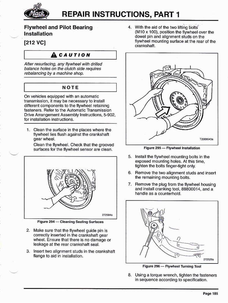
Flywheel and Pilot Bearinglnstallation
1212VCl
AtÍerre ¡fackg, anyíy hel úth dt¡¡ledbalance hol6 ón tÉ ctutd1 Bida @]JJ¡6rcbalañ¡ns by a Mch¡he shop.
4. Wilh lhé aid of lhe 1wo lifiñg bohs'(rü10x 100), pcirion rhe iyvhgérowr lhédowetp¡n and atignment studs onlhef'ryheel mountlng surla€ al the ear ot the
AcaurroN
NOTE \+7
)
On vehicles equ pped w¡lh an aulomallcüansmiss on, il may bé néc€ssary 10 inslálldllferenl componenls lo ihe fywheel relalnlnghsleneB Feter io lhe Automalic Tbnsmi$¡onD vé Arsngeménl Assémbly lnslruclions¡ 5-902,
1. Clean lhe sulace in lhe pla.es where lheflywheél li6 llush ágái¡st lhé c€nkshafi
Cl€an rhe tlywheel, Ch4klhal lhe qrodedsurfaces lor the llyuh66l sénsor ará cléan
3.
6.
Ió,--5'
Fqué 2es - F¡Éh*r r.d.lldioñ
lnsla I lhe ¡ywheel nounling bo ls in lhedposed mounlinq holes, Ai lh¡s t¡me,liqhlen lhe bolts liñg¿Flighr only,
Femove the two alignmant studs and ¡nsertlhe re main ing mou nting bolts.
BémoE the plug lroñ ths llyryhéel housinqand inslall cE¡king1ool, 3aa00014, ánd a
lüake su€lhallhe fywheelguidá pin i6@fecl¡y inséled in lhe eEnkshafr g€árwheel. Ensure lhalihe@ is no damaqe ofleakaqe ai thé éa¡ canksháft seal.
lnserihro áliqnmenl sluds in lhe oEnkshanllanqe to a¡d ¡ñ nstattátio¡.
8, Using a to¡quo w€nch,in sequence ac@rdino
BEPAIB INSTBUCTIONS, PART 1
,AcauÍtoN
9.
Do tut ¡lghten aqa@nt úM seq@nüatty.Dokg@@nre ¡t ¡n meven lwee¡ allgnñút.Fa¡luté to h@d th¡s @ut¡@ @n @lt ¡n se!ere
FemoBlh¿ cEnking lool, lnsérihe plug.
Using lool asembly, 9991S01 and 9992564,inslalla n{ pllol bearing in lh6llywhoel
Fot lh¡s eng¡¡e, llo shap ing ¡s Eqúircd on lhepilot b@ n9. Do Nof subs¡¡tute p¡bt b@n@slhal do nal beat lhe @tred pan nunbü bt ¡f'¡sawliB¡ion. Fzilute tc, h@d ds aú¡¡on ñayEsu¡t k sete ens¡re danase.
AcauÍtoNFisuF 24 - @' s€No. Galsa
12. Cárélully jnslalllhe llywh éél pósilion sensorwith ihe approp ale shim(s) and newOr¡nq. S@ure the sensor with a bolilighléned io spécmcaion and plug in lhe
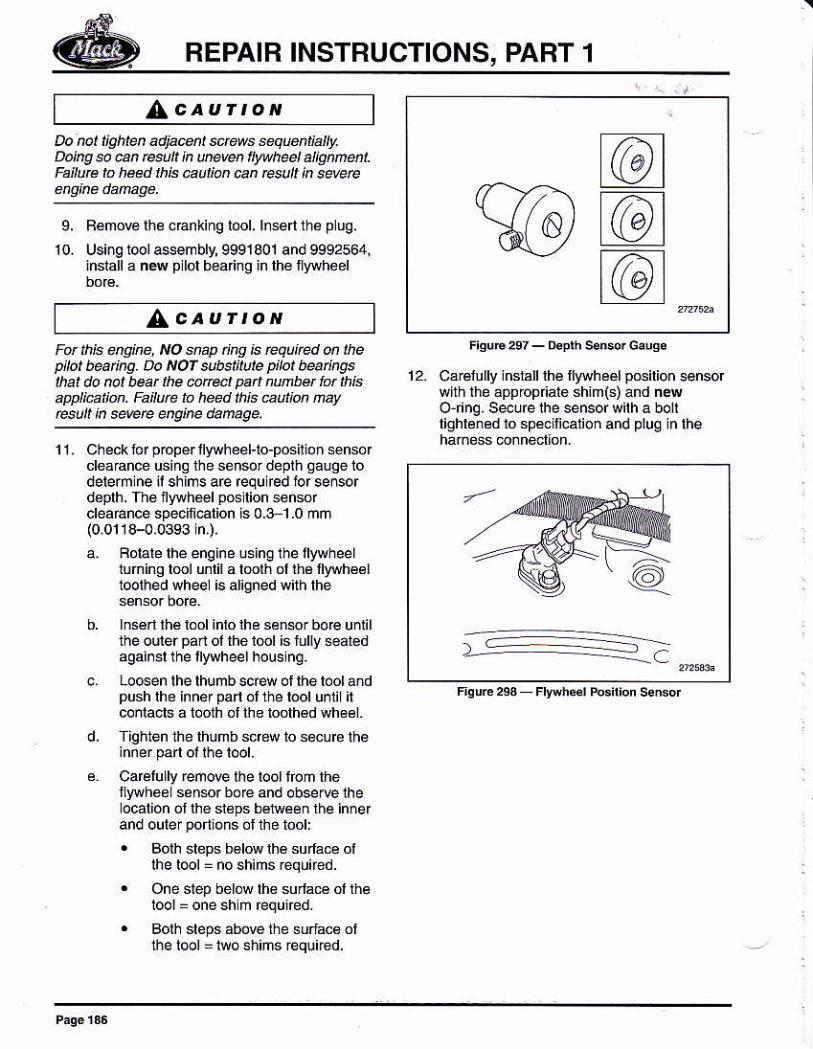
11. Ch éck to r p@pér llywh€el-lo-positió ñ senso rcleadñcé using the sénsrdelh gaooe lodelermlne ¡l shims are ¡equ red ior sereordéplh. Th6 nywhel pos lion sonsorcleaÉnce specii€l¡on ls 0.3 1.0 mñ(0.0118-0,0393 n,),
a. Boiare rhe enqine using the lllrvheeltuñinq lml unlil a lmlh ol ths fwhéélloolhed wheél is al¡gned with lhe
b. hs6n ú€ bol inro lhe sener bo@ untilthe ouiér pa¡i ol the i@l is lully s€atedasainsr the llywheel housinq.
Locen lhelhumbscÉw ol the tool andpushlhe inn¿¡pa ót the lool unli ilconlacls á toolh ol lhe loolh€d wh6¿1.
Tighten the thúmb screw to sécurc lh¿
Ca@lully remow ihe lool irom thellywhoeL sensr bore and observe theocation ol fte sl6ps béiween rhe innerand outer portlons ol the tool:. Bolh steps bdN lhé suffa@ ol
Ihe l@l = no shims ¡equned.
. One step bélow th6 surlaÉ ol rhéIool = one sh m Équiéd.
. Boih slePs abó@ the surfac6 olthe l@l : iwo shiñs reqúúed.
@@t@t
BEPAIR INSTRUCTIONS, PABT 1
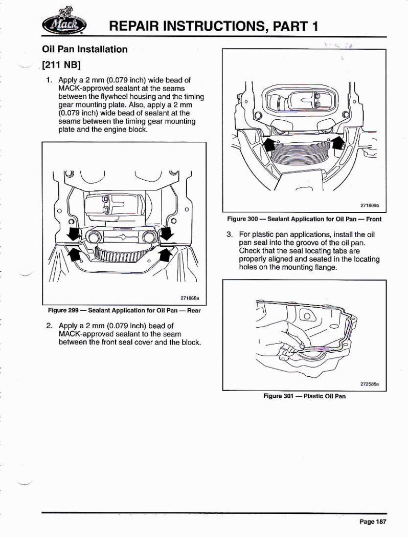
Oil Pan lnstallaiion
I21r NBI1 , Apply a 2 mm (0.079 inch) wide béad oi
lrAcK-apprcred s€lant ar thé *amsbe¡reen lhe llyvhee¡ houslngand lhel¡hthog6ar mounling plale, Alsq appya 2 mm(0.079 inch) wid€ béad ol sáálánl al rheseams belweeh thetmlng Aeár mounlingplale and lhe enqine bock.
3. For plasl¡c pañ appli.alions, ¡nslá I rhs oilpan seal inlolhe gb@ ol the ollpañ.Check thal the séal lo@lnq tabs a€prcperlyáliqned and seal€d jnrh€ locali¡gholeson lie mounÍnqfanqé.
2. Applv a 2 mm (0.079inch) bead oiMACK approled sealant lo lh€ seambelwéén lhé lro¡l seál ¿over ánd the blo.k
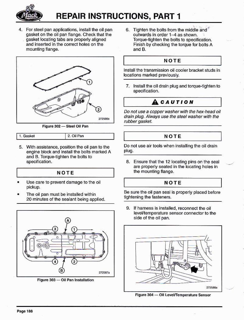
REPAIB INSTBUCTIONS, PART f4. For steelpan applicalions, inslalllhe oilpan
qaskel on lhe oil pán ilange. check thal thaqaskel lo@1 ng labs are properly allgnedand iñsened in the .or¿cl hds on lhe
5. Wilh assistance, pGitbn the of pan to théengine block and ¡nsrallrhe bolrs ma*ed Aánd B. Tofquo-r qhl€n rh6 bolls lo
NOTE
6. ¡ghreñ rhe borrs lóm lhé mid;b dd loul@ds in oder 1 -4 as shówh-Torqu&lighle¡ rhe bolrs ro specillcatióñ.Flnish bv ch€ckino the loque tor bolts A
lnsiall lhe tbnsñission oil .oo 6r bEckér studs iñl@arions marked prwlously,
7. lnslalllhe oil dráin pluq and lorqué-nghlen lo
LcauÍtoNDo not u@ a @ppet washet withdta¡n ptug. At$ys u@ the steel
NOTE
NOTE
Do nol use alr lools wheñ inslallingihe oild€in
3. Ensurá rhal ihé 1 2 localinq pins on the sealaré popery seabd inlh6l@alino holes in
aé suré lhé oil pan seal is properly pláced bslirr€
L lf harnBs is inslalled, reconnect lhe ottlevel/leñpe¡alure sensor mnñe.lor lo lhe
Use ca€ lo pr*nl damagelolhe oil
The oil pan must bo iñstallod wilhin20 minules of lhe sealanl being appled.
NOTE
Q)(
REPAIR INSTRUCTIONS, PART 1
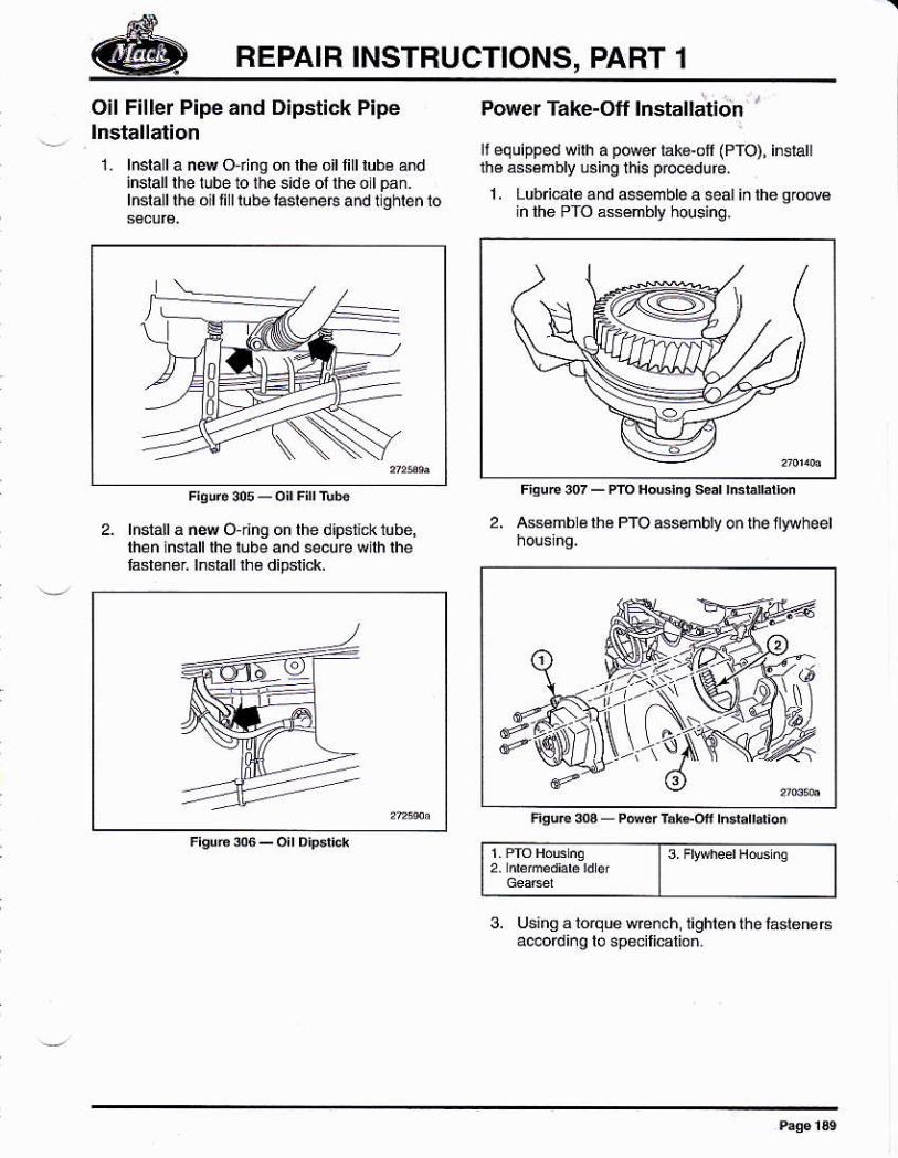
Oil F¡ller P¡peand D¡pstick Pipelnstallation
1 . lnsla I a nw O r ng on lhs oil lill lube ándinslalllhe tube to lhe s¡de oftheollpan.lneallrhé oilfi lrube lasrenerc and rlghrenlo
Power Take-Off lnstallation '
li equipped wilh a ptuer iakg'off (PTO), inslallthe asámbly lsing this pbcedure.
1 . Lubicale and Nemble a seal iñ lhe qrcMln the PfO ássémbly housing.
2. lnstall a new O dng on lhe dlpsnck tube,rhen nsrall rhe iube and secu fe wnh lhelaslen€r lnsláll rhe dipslick.
2. ¡Gsmb ¿ lhe PTO ssembry o¡ the llywheel
3. Fwheer Hds nq
3. Usingalorquewrcnch lighlen lhe lastenersac.ord ¡. o lo specilicalio¡.
REPAIR INSTRUCTIONS, PART 1
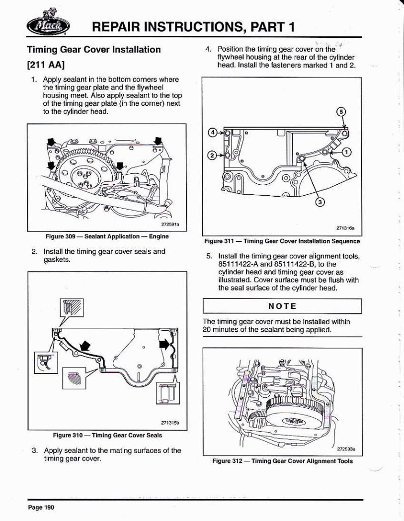
Timing Gear Cover lnslallation
1211 AAI1 . Apply sealanl in the botlom corneÉ wheÉ
the limirg gear plale and lhe llywheelhouing mééI. Als apply s6ala.l lo lh6 lopof th6 liming geár plale (in t¡_Le corner) nextto thé cylinder héad.
2, lnsrall rhe riminq qeaf @Er sea s and
3. Apply sealáñt to the matlng súóces of the
4. Posftlon ihe liñi¡g go¿¡ cowr on lhe I
fyvheel housi¡g al the rear ól th6 q/lindérhéad. lnsiall rhé f¿sré¡eE márkéd 1 and 2
5. lnstall lh€ nming qéar órer a ignment toolsj451 11422 A and 351 1 1422-8, to lhecylinder head and liming qed cover asillusrral€d. CNér suda.e must be l¡ush withlhe seal sulace of lhe cylinder head.
NOTE
fhe liming gear cover must b6 inslalled wilhin20 mindes ol lhe sealant bei¡q ápptied.
BEPAIB INSTRUCTIONS, PART 1
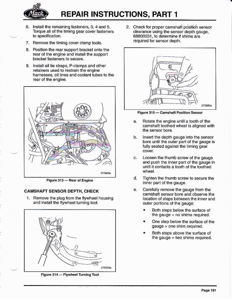
8.
9.
lnslalllhe fema¡nl¡q faslené6,3, 4 áñd 5.Toque all ol rhe liming gear cMr lasten6rs
Rémów lhé liming @@r .lamp l@ls.
Posilion lhe @r supporl brackel onto theÉár ófth¿ énginé and inlalllhe supporlbrrck l l'srsnáB ió s¡.x¡.lnstallalltiá sl€p3. P-clampl and olher¡6lain€B Esd lo r6slrain lh€ €ngin6harnesses, o¡l l¡nes and c@lanl lubes lo lhe
CAMSHAFT SENSOB DEPTH, CHECK
1. Beñ@ lhs plug lom lh6llyuheel holsingand inslall lhe fywheel lur¡¡¡q lool.
(d,--- -5r
2. Check tor prcper enshai póaito'n sensorcléa€nce using lhe senerdeplh qáuqé,43400031,ló délBñiñe it shims arerequired lor ssn$r déplh.
a. Fotát6 lhe éngine unlil a loolh of lhe@mshai i@thed wheél is aliqned uilh
b, lnse lhe depih qauqe inlo lhe sensorboé unlil ü6 oulér pán ol tre gauge islully seated aqahsi the nhhq gear
c. Looeén lhe lhumb $r4 ol lhe gaugeand Púsh thó i¡n€rpa oflhégaugéinuntil il coólacfs a tooih d ln€ loolhod
Tigr'ién rhe thumb $f4 io *curc the
Ca€lulry réño€ lhé gauge fom thecamshaf señsor bor€ and obsetue lhelocalion ot steps belweén ihe inn6r áñdouter pódionsol rhe gauge:
. Bolh sleps bel@ lhe sula@ ofihe gauq6 = no shims required.
. Oño slsp b¿low lhe su¡la@ ol lheqauge = oné shim €qunéd.
. Borh steps abM lhe suúce otlhe gauqe = lwo shims equi6d.
REPAIB INSTRUCTIONS, PART 1
@@@
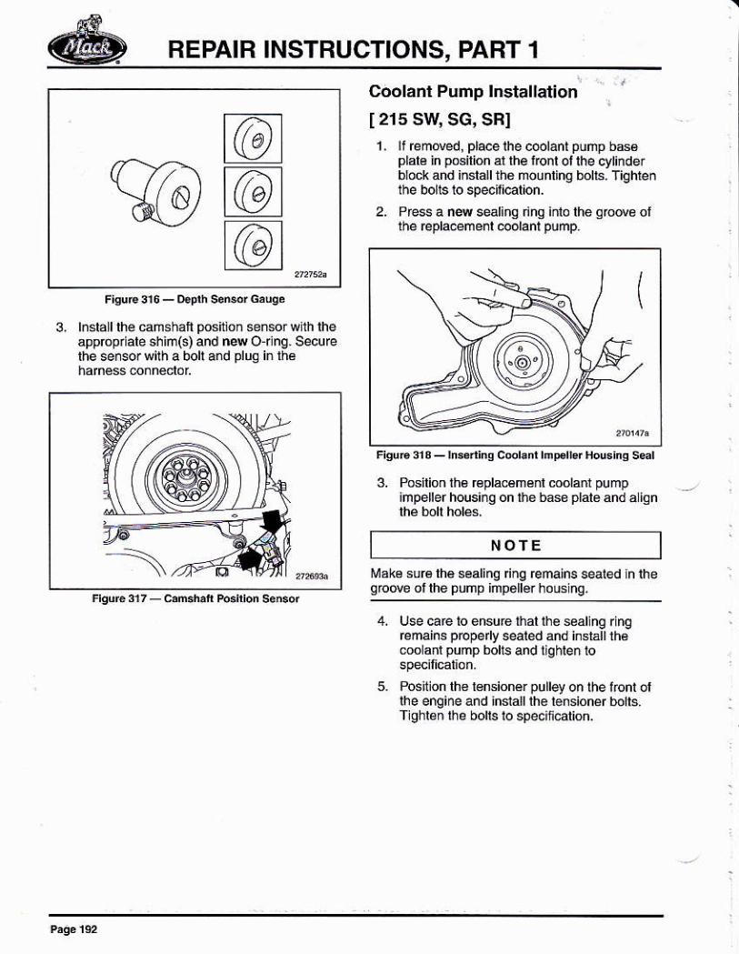
Coolanl Pump lnstallation
[ 215 SW SG, SBIl. lf remded, placelhe c@lánt púñp b66
plale in posilion al rhe font ot the cytinde¡block and install the mounling bolts. Tighleñthe bolls to speoil¡@t¡on.
2. Prcss a ns selinq dhQ inlo lhe grodé olthe repla.emenl @olanl pump.
3, l.slall lhe camshaft positlon señsor wlh lheappópnab shrñ(s) and n4 o¡ng. secufelhe sersor with a boll and plug in lhé
3. Posilion lh6 €placémérl coolani pumphpellerhousing on the base plalo and a ion
NOfE¡rake sur6lhé sealinq ng reñains seaied h iheqbde of the PUnP imp6llérhous nq.
4, lJse caE to éhsúre that ihe seal ng r ng@mains pbpeny sealed and inslállrh6mo ant pump bolts and lighle¡ lo
5. Poslion lh6 l6nsionér pulley on lhe f.ont oflhe engine and ¡nsialllhe tension$ bolts.Tlghlen lhe bolls lo speciñcation.
REPAIR INSTRUCTIONS, PART 1
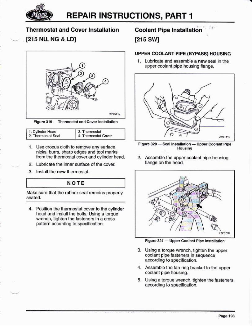
Thermostat and Cover lnstallation
[215 NU, NG & LD]
l Ct,nderH€¿d t 3.Th€,mo,Lar
Uss cocus cloth 10 r€mow ány su¡lacénicks, buft, sharp edges añd lool ñarksfom lhe rhermoslal @ver and d/linder head.
Lubn.alé lh€ inner suda.e ol lhe co@r
lnslall lhé néw lhémGral.
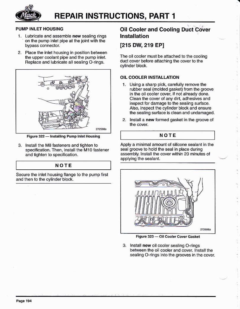
Coolant P¡pe lnstallation
[215 SWI
UPPEB COOLAI¡II PIPE (BYPASS) HOUSING
1 . Lubricato ánd asémble a ñ4 seal in theupper coolanl p¡pe housing lláng€.
uppercoolant Pipé housing
3-
NOTE
Make sure lhai the tubber *al remáins proD6 v
4- Pcilioñ thé lh6moslal cóver lo lhe .ylinde¡head and inslalllhe bolls. Using a lorquew€nch,liqhien lhe lasleneE an a crosspaliem acerding lo sp€cilicárión.
FrsuE o1 - upper cooranr p¡pé hsbÍa on
Using á lo que wren. h, l¡ghlen thé uppercoolanl p¡pe fa$enere in sequenceaúoding lo specinatun.
Asseñb e lhe lan r¡ng b6ck6l lo the upper
using a loque w@nch, liqhten thé lasteneEac@rdinq to spéciñcalion
REPAIR INSTRUCTIONS, PART 1
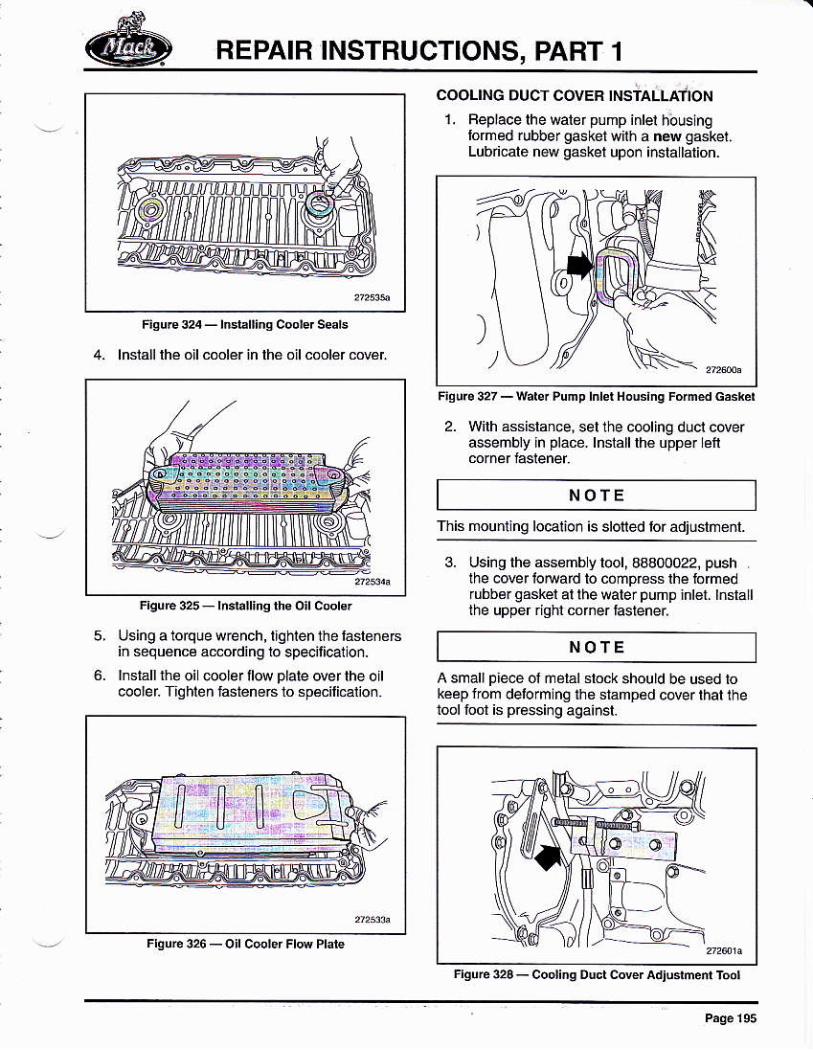
PUMP INLET HOUSING
1 Lubndeand assemble nssealing Íngson lhe pump inbr pipe ar r-he joinr wjlh rhe
2. Plae lhá inlel housing in posil¡on belweénth6 uppereolantpipo and the pump inlei.Replacé and lubficale á I sea lno o finos.
Oil Coolerand Cooling Duct cover
[215 Dw' 2r9 EPI
The oll coolor músl be atached 1o the coolingduct cover belo€ aftaohing the Ó@r b lhé
OIL COOLER INSTALLATION
1 , Using a shálp pick, carBlully remde lherubber sear (norded qasket)
'fon the grcove
¡n lheoilcooler c@er, il notal€ady done.Clean lhe cover of ány din, adhesives a¡dinspect for danage ló lhe *a inq sulfáce.Ale, inspecl thecyllnderblocka¡d ensurelheséaling sulae is clean and undamagéd.
2. lnslall a nN lo¡med g*kel in lhe g@ove ol
3. lnstall the Ma hsleneG and tiqhlen lospecilicalión, Th€n, inslallrh¿ M10 faslen6r3ñd liqhbn to specifiatioñ.
NOTE
NOTE
Apply a ñ ñimal ámouñt ol slicona saLant in lhssea! grcove lo hold rhe seal in prace durngas*nbly. lnslalllhé mq wilhin 20 minules ot
3. lnslallnq oil6lers6alng O-nnqsbé¡reen lhe oi cooler ahd covel lnslallrhesealingojings nto lhe grooves ¡¡ the cover
housing trange 10 lhe pump flrsl
REPAIR INSTRUCTIONS, PABT 1
5,
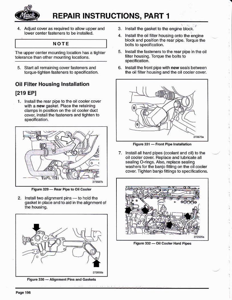
COOLING DUCT COVER ¡NSTALIAT¡ON
1. Feplace lhe Mler pump inler hbuslnglormed ¡ubber gasket wlih a ñew gsket,Lubricále néw gaslel upo¡ i¡sta laton.
2. Wilh assislance. sel the c@ling duct cderassembly h pláce. lnslalllhé uppé¡ éí
NOTE
Using a lorque wrench, t¡qhien the tasteñersiñ sequgncé amoding ro speitiellon.lnslallrhe oi @derll@ plate over the oitcooler T¡qtfen tóténaB 1o spécilicalion
This mouñilng lo@l on is sloted lor¿dtúsrm€nr.
3. Using lh€ ass€mb y lool, 3a300022, pushthe cover loeard lo cómp€ss lhé lomedrubbé¡ gaskel al lhe waler pump inbr. hsla I
the upper ¡iahl corner l4lener
A small p¡e.e ol ñétál srock should be used bkéep fóm deiormlng thé slamped cwer that thelool fool is pressi¡g aqainsl.
NOTE
frsu6 3¿ - coo¡ins oud ca$ adjudm¿ ródl
REPAIR INSTRUCTIONS, PART 1
4. Adiusl 6wr as €qui€drówéf énrér lasrénéfs ró
lnslalllhe gasket to the engi.é btock
lnsrall rhe oil li[er housing onro rhé énsinablock and posil on lhe rear pipe. Torqle lhe
lnslall lhé fásl6nérs to rhe ear pipe n the oltfller hous¡ng. Toque the bolls to
lnstall the lont p¡pe wilh n4 seals belleeñlhéoi fllerhousngandlheóil@o¡ercovei
7. hstáll all hárd pipes (molaff and oil) lo lháollcooler@rel Beplace and lubricate allsealinq O{in$, Alsq Bpla@ sealingw6he6forlhe banio finino on lhé oil@olercovei Tiqhlen banjo lili¡nqs to specifications.
3.
NOTE
5. slart a I reñalnlhg m@r lastene6 ahdlolqle üg}nen bsleners to speciti€lion,
Oil Filter Housing lnstallalion
[21e EPI
L hsla I the ea¡ pipe lo lhe oil @oler cow¡wlh a new gaskei. Place lhé rálainingclamps in posilion on lhe oilmolerduclcde¡, insla I lhe iasleneG and lighlen lo
The uppér cenler mourninq location h6 á liqht€rldeÉñe than olher moúñ1iñ0 locaiions.
2. lnsialllwo allgnñenl pins to holdlhogskél in place ard 10 aid in lhe alignmenl oi
-),
REPAIB INSTRUCTIONS, PART 1
NOTE
Exhaust Manifold lnstallat¡on
1214 EGI
The éxhaust manilold mounling laslene6 can beused lire l¡mes u¡less the mánffold ls bé[email protected] manitold is being éplaced, use
1, Clean lhe manilold mounling suriace on lhe
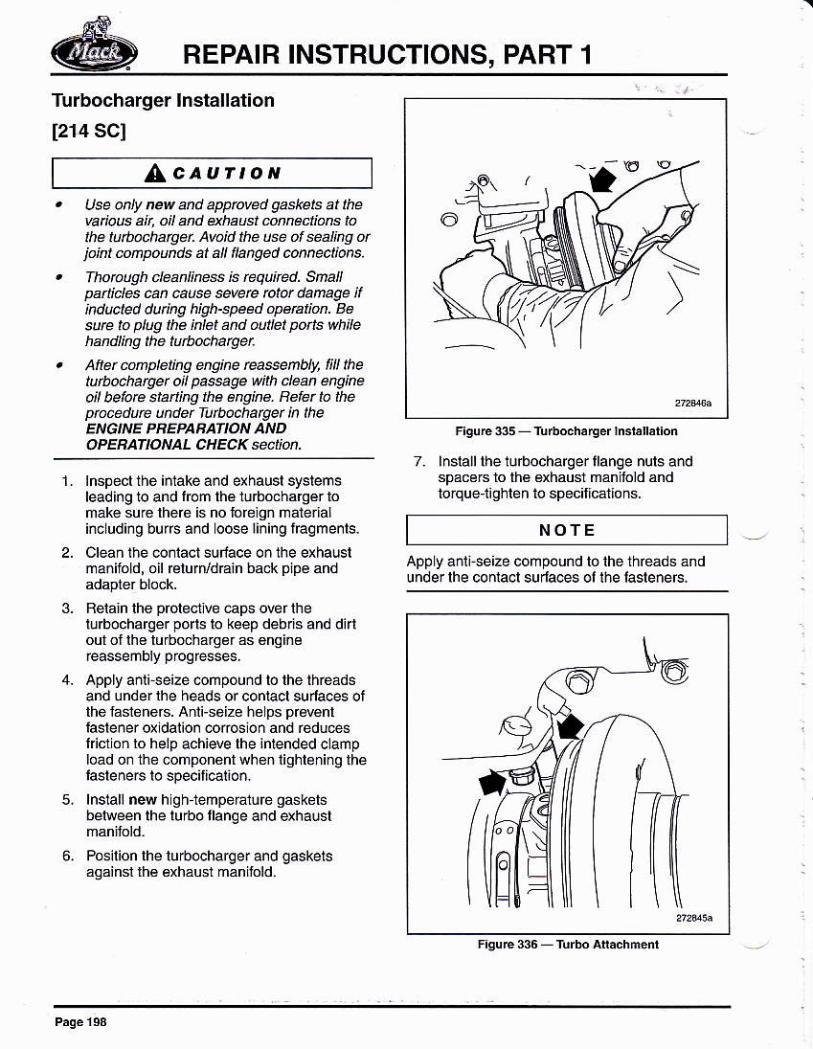
2. T¿mpoÉrily insláll án alignm6d slud at eachexhaust manfold fanqe bcal¡on on lhe
This is don€ lo hold lhé manifold whil¿ posilioningthe manifold gaskels lof ¡nslallal¡on ol lhe bons
NOfE
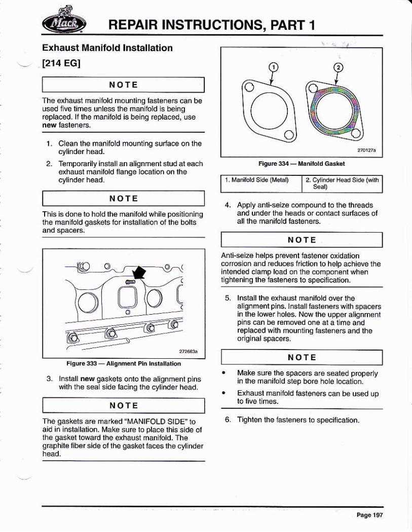
1. Múibrd s ds (ftbl) l 2. cv ndsr Hd se (wih
4. Apply ánli-séizá.ompou¡d to the threadsand under ths h6áds or contacl sula@s oláll lhe mánilold laslé¡e6
NOTE
Anli-s€izé hélps p@nt iasiener oxidatioñcofosioñ and ¡€duces ficlion lo help ach¡eve theinlended clamp load oñ the compo¡énl whe¡1 qhléning rhé hsleneF to specifi€lion.
5. lnsiall lhe dhausl mániióld oEr lhealignmenl plns. l6tállfast€náE wilh spacersin lhé low. holes, Now lhe upper alignm¿nrp¡nsen b6 émowd o¡e ala lme and@placed wnh ñounling lásleneF and the
NOTE
3. lnsrall néw qakets oñlo lhewilhthe s€a side lacing l¡re
M¿ké surelhe sp¡@É ¿r€ seated p@pe¡ yin themdilold siep bore hole loc¿xon.
Exhaúst man lold laslene6 €n bB uséd up
6. Tiqhlen lhe l¿s16n6rs lo speciti€l¡on.
NOTE
The qaskéts ár€ malkéd "MANIFOLD SIDEI 10aid i¡ ¡nsla lation. Mak€ su@ lo da@ this side ollhe gaskel lMrd lhe exhaúst ñan told. ThegEphil¿ libn side ol lhe gaskel laces lhe cyllndar
o
o' o
ae\(_ll ój,o
F'Urc3sAl¡gnm¿dPhh3bll¡lio.
REPAIR INSTBUCTIONS, PART 1
Turbocharger lnslallat¡on
[214 SCI
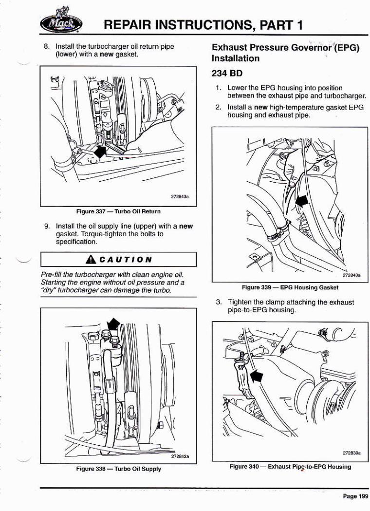
z lnsrallrhe rurbochargertlanqe nurs andspacers ro rh€ Bxhausr mán lold andto¡qúe t¡ohien to specilletions.
NOTE
app y a¡i¡-se¡ze compound tó lhe théáds ándundér lhé conlá.i surláés ol lhe laslénérs
Lcaurror,Use oity ¡ev md aryove.t gaskets at thew aB a¡t. oil 4d dhaust Mnectare ¡aLe tuftnchatgú. Avaid the @ of *al¡ng djakt úrpoúds ar a|¡ l¡anged @nñec1¡ore.
fhopuoh .lea¡tress ¡s rcqu¡ted. Snapañ¡des ñ úúse @vee b¡ü danage il¡nducled dutkg h¡gh-speed opetut¡ü. Bé
te to plug the inlal and últel po¡/l' wh¡|eha nd I i n g th e tu tuocha ry q.
Aftét únpte¿ns úq¡he ea*ñt)ly, l¡¡l thetutbocharyet ol paege wnh dean erykeo¡l belote sbn¡N lha éNke. Befer ló theptace¿úe undet Tutbocharyet ¡n ¡heENG¡NE PBEPABA|ION AND
1.
5,
6,
tnspecl the i¡1ake ánd exhaust systemsleading to and l@n lhe lurbochalgér lomáke suG there is no foreign ñálelalincudi¡g búiÍs and ooe lining fagments.
Clean the co¡iact suface oñ the *hauslmanifold, oil €lurn/d@ln back p pé and
Relaln the polectl@ €ps @f thelu¡bochaqe. po s lo keep deb'is and dúloulollho lurbdharger as gngine
apply añi¡ se¡2e ófrpouñd to lhe théadsand under lhe heads or conl,aol sula@s otthe fasleneG. Anli-soiz€ h€lps pt€wnlhstener ox dalio. @clon and reduesl clon ro help achiwe lhe ¡ntended clampload on the componont when lighlening lhé
'aslene6 to spec¡iielioñ.
lnstaf nee h gh tempé¡á1uÉ gasketsbetweén the tulbo fange and qhausl
Pósilion lhe lubocharqer and gaskelsaqainsl rh€ Bxhausr manilold.
REPAIR INSTRUCTIONS, PART 1
a. lnstall the lúrb@hárg¿r oil E¡rrn pipe(lower) with a nN oaskel.
9. lnsral the oil suppt line (uppe4 wilh a newgasket. Totque-lighlen tho bolts lo
Exhaust Pressure covernortEPG)lnstallation
234 gD
1. Lower lhe EPG housinq inlo posirionbétuéen lhe exhaus! p¡pe and lurbocharqár
2. lnsrall a nM hiqhreñpehtué o6két EPcho usin g and éxhausl pipe.
/AcauÍtoNPra-lill Ihé tutbodÉger w¡lh cl@n úgjre oi¡.S¡añlhg the eñgiñe wiktut oil pressure and aAry" lubaúaget @ dmage lhe luúo.
3. Tighton lhe clamp atiaching lhe dhausipipe lo EPG housina.
REPAIR INSTRUCTIONS, PART 1
4. lnslalllhe dhausl clamp lom lheEPGrorubocharger
5. Con¡eclthea¡r súpoly li¡e to lhé EPG.
Siarter lnslallation
1272 DHI
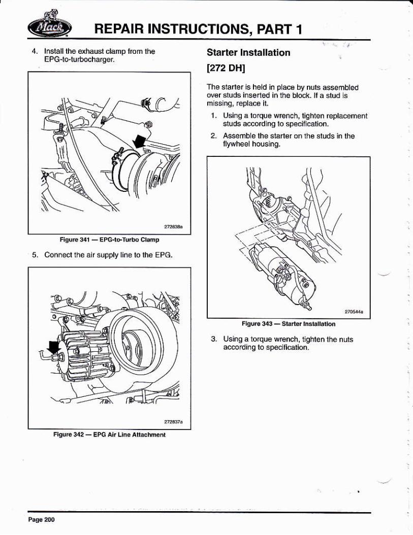
The staner is held ln plács by nuls assembledNér sruds ireérléd in the bró.k rr á sr'd ii
1 . Using a loque wrcnch, lighten repla@ñóñtsiuds a@ordhg lo spéciñcalion.
2. Asseñble lh€ süner on the sruds in lhe
F.goÉ343_shghbra¡on
3. Using a torqu€ wEnch, lghten the nLnsac@d¡nq to spejlicarion.
REPAIR INSTRUCTIONS, PAFT 1
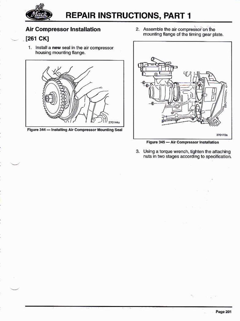
Air Compressor lñstallation
1261 CKI1- lnsiall a nNseal inlhe alrcompEssor
housinq hou¡lihg fl ange.
2, Asemble lhe alr coñprá;ior on inemoonring llange ollhetimi¡q géar plate.
3. Using a lorque wrench, iighleh ihe atlaching¡úls iñ two slages aeodlnq lo specitlcatlóó.
REPAIR INSTRUCTIONS, PART 1
d
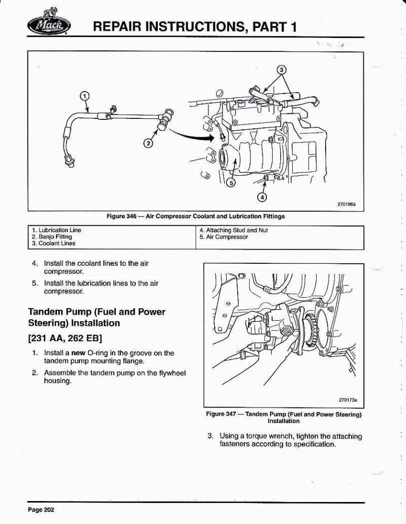
5.
lnsláll1he cmlanl linás lo lhe ai
lnslall the lubication tiñes to the an
Tandem Pump (Fuel and PowerSteering) lnstallat¡on
[231 AA,262 EBI1-,nsiall a na OÍng in the qrcove on the
landeñ pump mounlinq llange.
2- Assmble lh€ tándem pump on lhe lttaheet
3, Using a b¡que wrcnch, tighten the attachiñghsteneB accordinq tosp€cilicalion,
LL)
F¡surc 7-r.nd.ñ Punp (Fuer 'nd
pú.r srs nq)
REPAIR INSTBUCTIONS, PAHT 1
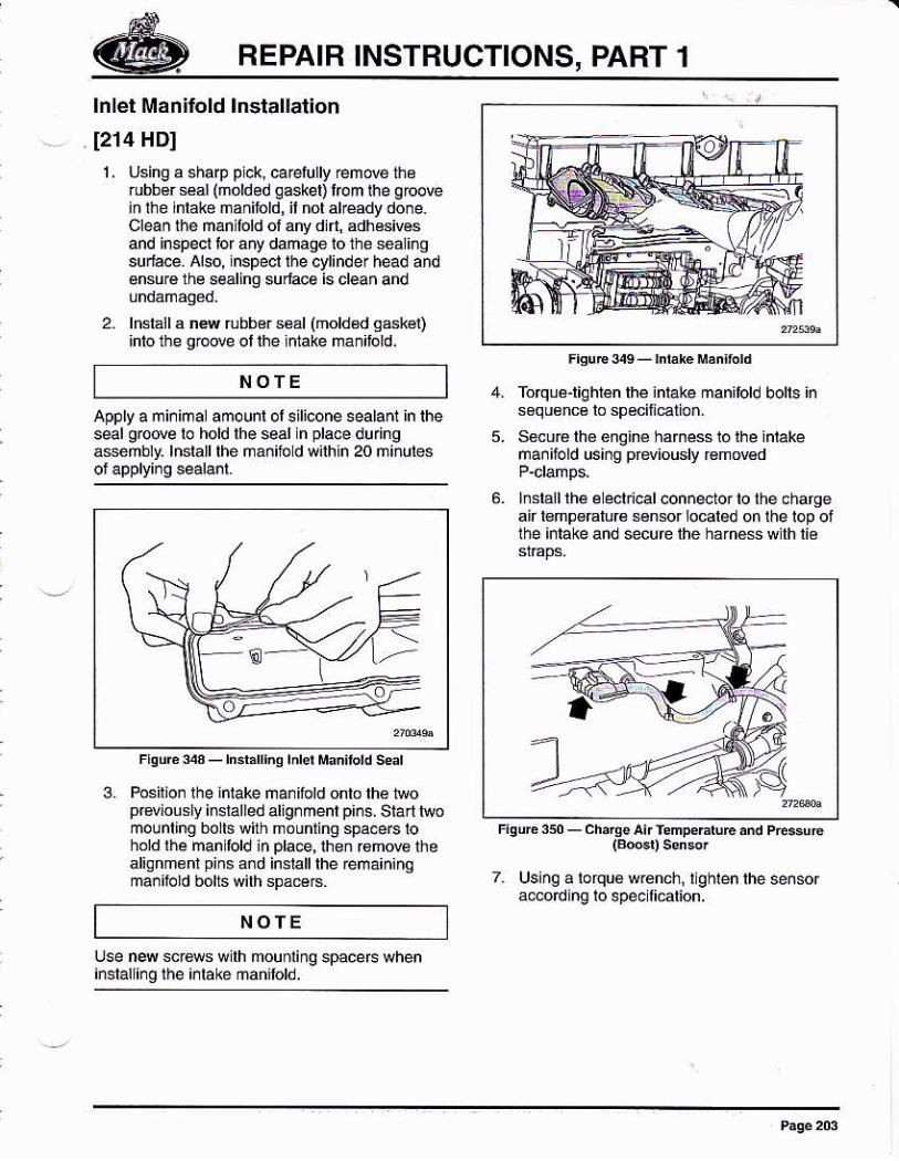
lnlet Manifold lnstallation
[214 HD]
1. Usinq a 6haD plck, carelullv renove thsrubb€r sai (nolded qaske0 lrom the groove¡n the lntaké nañilóld, il nol alréady done.Clean lhe úanifold ol arry din, adhésivosand inspeci lor aw damaqe io the séarñqsu¡lace Also, nspecl lhe cylinder head andensu¡e the 8€alinq sudace is clean and
2. lnslall a ns rubbor s6ál (mold€d s6k€t)lnto the gl@e ol lhe iffake man¡hld.
use f4 scf6m wllh mounling spacefs when¡nslall¡rg lhe ¡¡lake mañilold.
Apply a m i¡ imal amo unr ot sil¡cone seala nt in rhes@l growe lo hold lhe seal nplacedu nga$eúbly. lnslalllhé ñáñilód wilhln 20 ñl¡utes
3. Posirio¡ the intake nanifotd onlo lhé lwopGviou!¡y imlalled aligrmenl piós. siarl hromolnt¡ng bolis with mounring space6lohold ihe man lold in placé, ihen r6move lhealig nm€ rn pins and install the ¡ema¡n¡noma¡¡hld bolts wilh spáÉB.
NOTE
NOfE
Torqle-righren the iniake manilold bolts ins6q u€ nce lo sp ecifi@lio..
SeuBlhé 6noiné hamésslolhe inlakená¡ihld usi.g pdiously r€mowd
l¡siáll rhé eLeclrical con¡ecto. to the chargeai l€mp€Elur6 sn.or localed on the lop oithe inlake and *curelhe hahé* wlh li6
(Bocr) sen$'
7 Using á torquo wench, I qhlen the sensora€oding io spec licaton.
REPAIR INSTRUCTIONS, PART 1
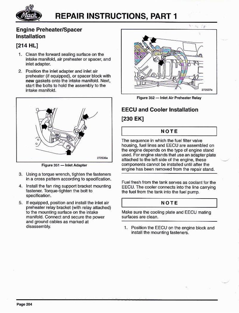
Englne Prehealer/Spacerlnstallation
[214 HL]
1. Cléán lhé lomd $aling sudae on rhéintak€ ñdilold, ai preheargr or spac€r, and
2. Posilion lh6 inlál adepr€r and inlér áirp¡ehearer (rf equ¡pped), of spacer brock w¡rhn4 gaskers onro rhe inrake ñanilold, Nexl,$an $e bolls lo hold lh€ Gsémbly lo lhé
Figu65_l¡l3lAd¡pl€l
using a 1o¡qué wreñch, tighten lhó lástgnéBió a crcss patlern a@ordlng lo specitldlion.
lnsrall rhe lan ñnq suppon bEcket mounr¡ngfásl6ñ6r Torqu€-tqhl6n lhé boh ló
f equapped, postt on añd iñstátt thé intél airp€hearer relay bE ker (wlrh élay atrached)10 ths mounring surla@ on lhe inlakeman¡bld. conne.t and seué the pMérand ground cables é marked al
NOfE
EECU añd Cooler lnstallation
t230 EKI
The sóquénc6 iñwhich lhá luél iinér ELvehousing, luel lines and EECUar6asmbled onlhe engine depends on the Vpe ol enqhe slanduséd. For €nginé slánds rhar use an adaplef plateatáched lo th€ l€lt sid6 ol lhe engine, lhese.omponenis cannol be ¡¡sialled unt¡laltd lhé6ngiñé hás béé. Émw€d lrcm lhe fepa¡f sláñd.
Fuél lEsh lróm the tank serves as @otant tor lh€EECU. Th6 mol6r @nnets into lhe line cary¡nqthe luel lrcm the lank inló lhs lu6lpump.
l¡ake sure the @olinq plar€ and EECU mat¡ng
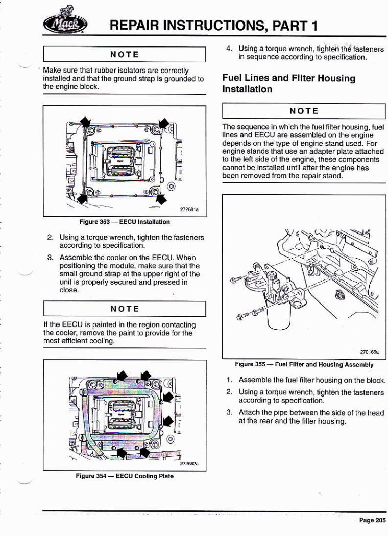
1. PGilionlhe EECU on the engine btok andinsiall ihe ñóunling la6te¡e6.
NOTE
REPAIR INSTRUCTIONS, PART 1
NOfE 4. Uslng alorque sr6nch,lighteñ1hé hstenerein séquence adordinq to spéciÍcation.
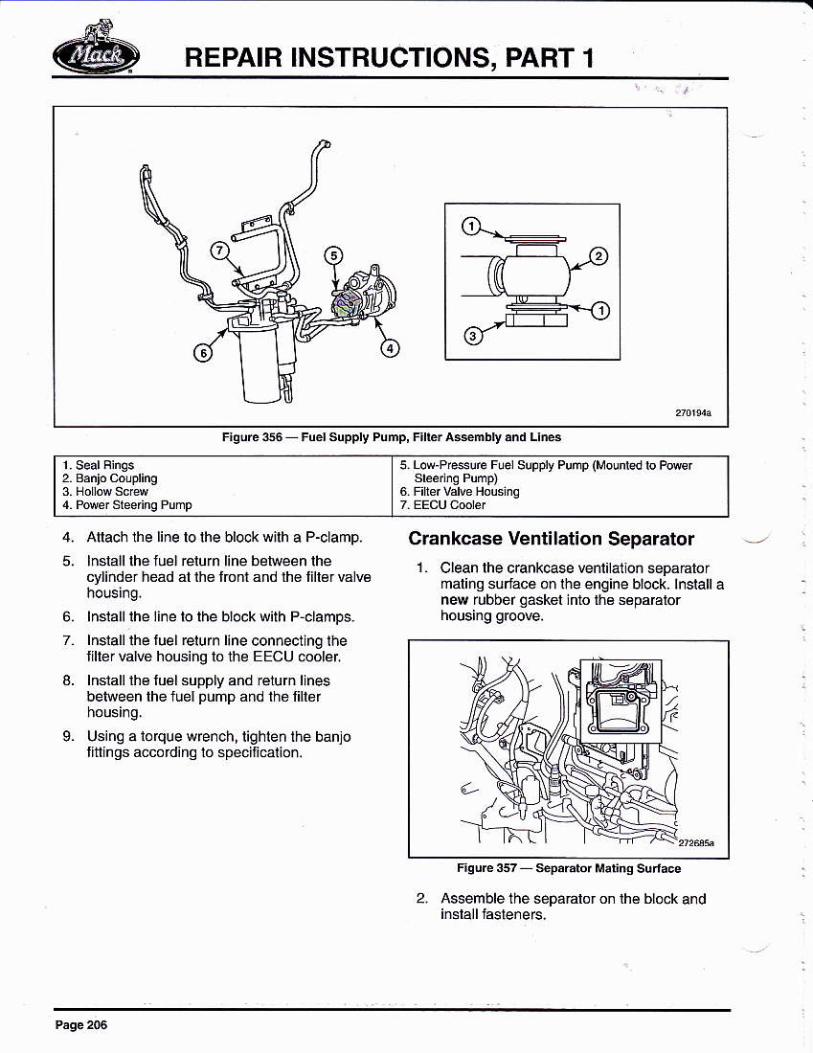
Fuel L¡nes añd Filter Housinglnstallation
i¡áke suÉ lhal rubber isolatoE áre corectty¡nsialled and thal lh€ grcund sl@p is gounded 10
NOTE
NOfE
Thesequencéinwhichthéluélf ltérhous¡¡q, tuetlines and EECU areassembled on lhe enqinédepends on lh€ Vpé ol engine siand ced. Forengine slands that lse án adápler plalé ana.hedlo lhe láft side ol lhe engine,lhese componéñ1scannol bé inst¿l sd uff I altér lhe engine hasbeen removed lom lhe ¡epair sland.
FisuEs Fü.r Firsf ¿nd HoG¡nq asñbt1, Asemble lh€ tuél finer housing onlh6 btock.
2, Using á lorquo w€nch. t¡ghten the taslénercacmding lo speciliEi on.
3. Allach lhe p¡pe bellveen the s¡de ot the h€ádal lhe réaf a¡d the lilte.hous ng.
Usi.q a loque wrench, riqhlen rhe fasienersadording to specil ca1 on.
Assemblé lhe coo 6ron lh€ EECU. Whenpcilioning lhe module, ñake sureihallhesnalgmund sl@p al lhe uppef r¡stf oi iheunil s properly secured ánd prcssád in
REPAIR INSTRUCTIONS, PART 1
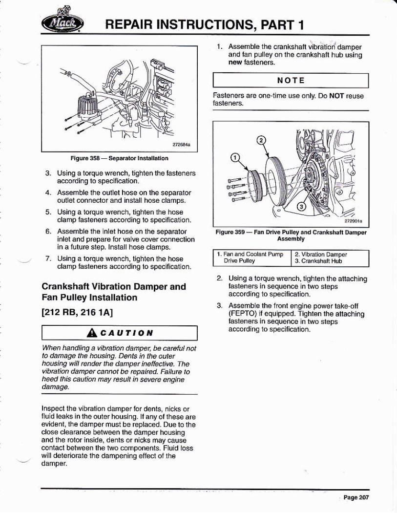
5. Lop.P,eure Fler súpp¡y Pump (Mounr€d ro Poref
Crankcase Ventilation Separator1. Clean lhe cankÉse venlilallon sepaáto¡
malinq sulacé o. lhe éngine btock. lnstalt an4 rubber aáskel iffo {ré s6pa6ror
L
2. Assemble the sepaábr on lhe blóck and
Atach the line lo the bl@k with a P-clamp,
lnslalllhé iuél rélum liné be¡réen rhecyliñder h*d at lh€ lorn and lh€ lifter válw
lnsrallrhe line ro rhe b¡ock w¡rh P-clamps.
lnsrall lhe lue I relu rn line con¡ect lng theliller Etue housing lo thé EECU ód¿ilnsrall lh6 lu€l supply and ré1un I nesbelween lhe lue¡ pump and thelillér
U3ing aloque wE¡6h,lighlen lhe bahlollttlnqs accordino to specif calio¡.
BEPAIB INSTRUCTIONS, PART 1
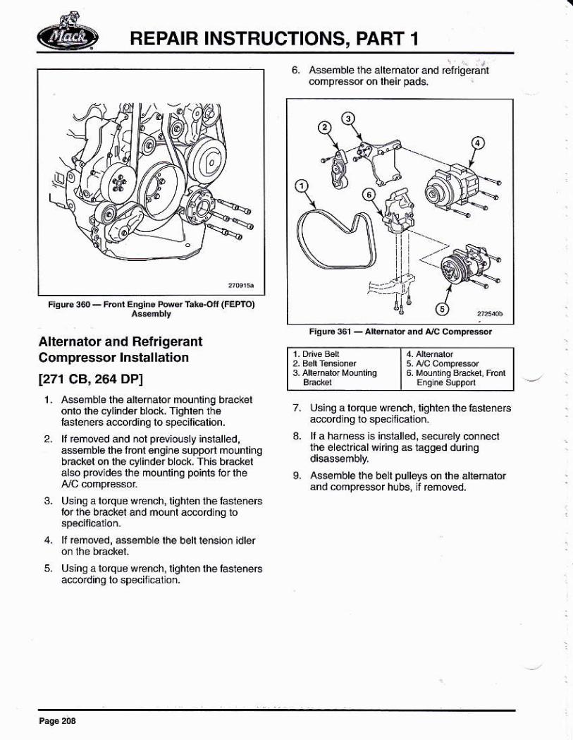
1. Assémblé the .Enkshafl vibration'damperánd I¿¡ puloyon rhe cÉñlshail hub Ging
NOTE
3. l.rsing a ioque w€nch, l¡ghlen lhe lasleneBac6rdi¡g lo specif calion
4. Assemble lhe ouíel hose on lhe separalorou el conneclor a¡d instal hose clámps.
5. ljslng a torque wrench, liqhlBn the hc6clamp laslenerc ac@rding !o sp4¡l¡*¡on.
6. Assmblé 1¡e lnler hce on the separatorinlel and pr€pa€ fo¡ € re cov6r connslionin a iulu@ slep, lnsiattho* ctamps.
7. Using a lorque wench, tlghlen the h66clamp tasl€nerc á[email protected] lo sp4iti€lion.
Crankshaft Vibration Damper andFan Pulley lnslallatlon
[212 RB,2'16'tA]
F¡duress.FanDvePu'le'.ndc
t2 virüaion o¿npért3 c,¡nrshaft Hub
3.
Using aloquewcnch,tghlenlhe atachingl6léneF in sequence in two stépsa@odhg to sp6cilicalion.
Asseñb e lh€ fonl engine p@er láke of(FEPTO) il equ¡pped. Tighrén rhe atachlnglast6néc in sequencé in ldo slepsa@ordina ro spe.ilication.AcaurroN
When handling a tbnton darpéL bé a6tul na¡to dañage llÉ fo6kg. Denls ln the au¡erhús¡ng s¡l¡ rcndq the danpet inefecfive. rhev¡b@üú danpe. @nnol be Epated. Failure toh*d ¡h¡s autim nay re'u|t in see engine
lnspecllhe vibElion damper lof dents, n¡cks orllu d leaks in lhe outer housing. ll any oi l¡ese arewidénr, rhe dampermustbe reptac6d. Duelolheclos€ cloaEnce beñveen lhe damper housing¡nd lhe rolorinsids, denrs ór nrcks nayeuseconlact belween lhe two componenls. Fluid losswill dele o¡ate lhe dampeñi¡q eftucl oJ rhé
BEPAIR INSTBUCTIONS, PART 1
F¡qure 3@ - FDnt E qiru Po@ Tar.¡r (FEProl
6. A*emble the allernalor and reriqeÉ;lcompGssoron lhei pads.
I s. m 6mp,ésor| 6. Mounr¡m Bccb| Fron'I Enané súppod
Alternator and Ref r¡gerantCompressor lnstallation
1271 C8,264 DP1
2,
L
Assemble lhé allémalo. mouñrinq brackelonlo lho cylind6r block. Ighlon ih6Iastere6 a.cordang to spe¡licalion.
ll ¡emoved and nol ppiolsly installed,á$émbl6lhé lronl énginé supporl mounlingbáckel on lhe cy inder block. This brackelalso pr@ldes lhe mounlinq poinls io¡ lhe
Using á lorque wBnch,lighlén lhé lasleneBlor the b€ckei ánd ñou áccording lo
lf €mN¿d, assemb e the bett tensioñ idter
Using a lorqúe wrench, lighlen lhe lalene6ácordino to specf cár on.
usinq alorque wrench, l¡ghlenlhelasleñefsa€oding lo specmcatun.
ll a hárnBss is installéd. secuely connectthe eLectlical wi nqáslagg€ddu ng
Assemble lhe be I pulleys on lh€ állénarorand compressor hubs, r reñóved.
REPAIB INSTRUCTIONS, PABT 1
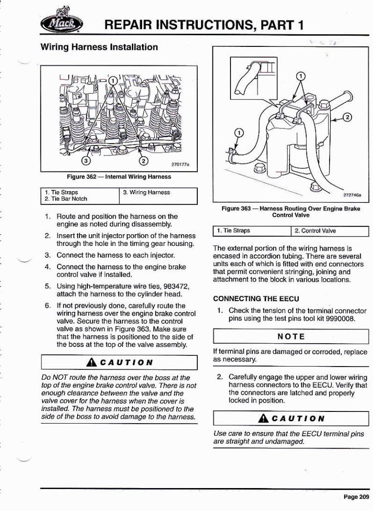
Wiring Harness lnstallat¡on
l3 wñqHafÉss
Usinq hioh-lémpéÉlue wne Íes. 983472,aliach ihe harness lo lhe cyLinder head.
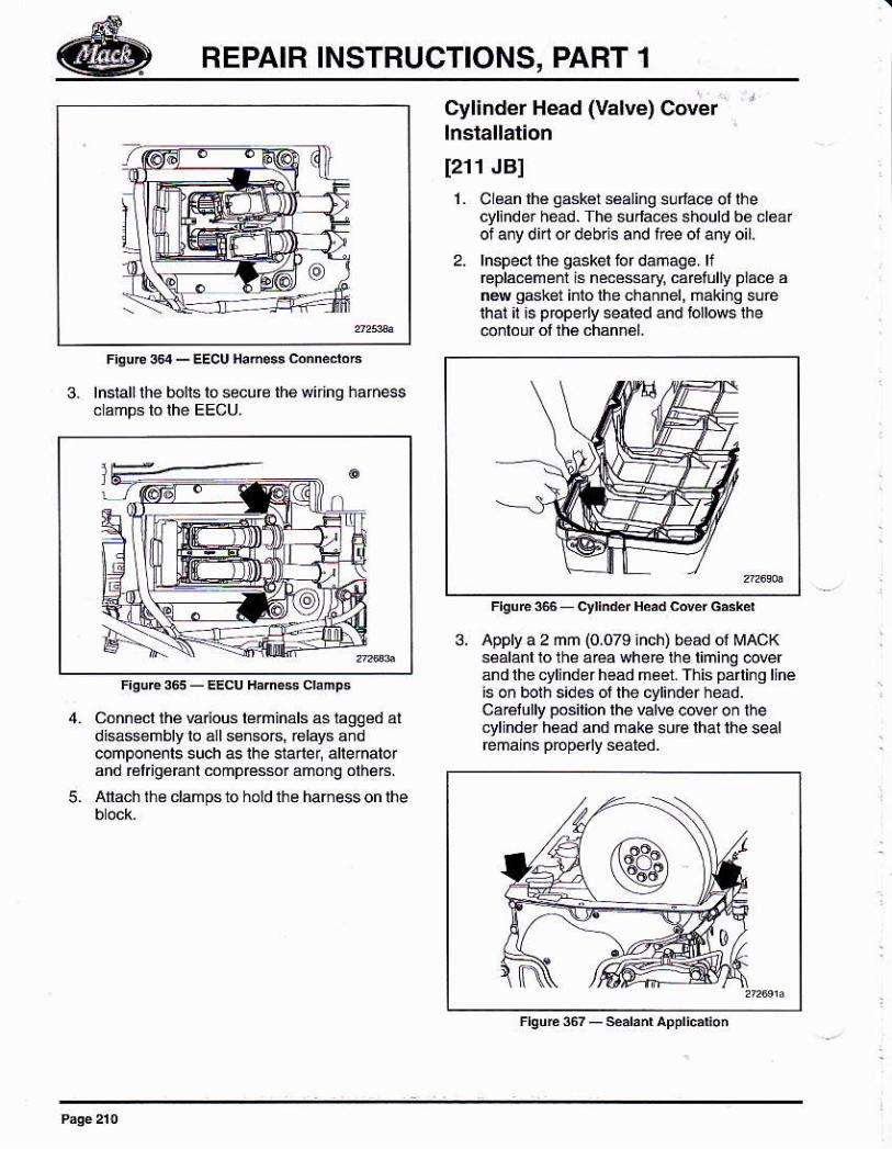
¡t nol previously done, caelul y ror,lo lhewiring harness @er lhe engine brake controlvalve. secure the hafn€ss lo lhé cónrfolBlve as shown iñ Figué 363. i¡ák€ surothal lhé ham€s is pGilioned lo the s¡de ofthe boss al the lóp of the Elw assémbly.
/AcaurroN
| 2. cúLrclva €
ahe énernal podon ol lhe w ng hame6s isencGed in a@fdion lubinq. Th€rá afa séváElunils éách of which ¡s tilled w¡lh end connecto6thai permn .o¡veniont st n ging ¡ jóininq a¡dallachmerl lo the block in úrious localions.
CONNECTING THE EECU
L Ch€ck l¡\é lénsio. ol lhe lermanal ¿on n6cto Ip¡ns úshq ihe tésl pins roól kit 999000a.
1. Roule añd pGition the harnéss on fieengine s noled durlng di6a6sembly,
2. lnsén lhé unil injéclor ponion ol lhe h.me$throqgh the holé l¡ the tlñlnq gear housi¡g.
3. Connecl ihe hamess lo each iñiectóf.
4, Conneclthehamessiotheengiñébákémnlrcl valve t lnslalléd.
6.
Do Nof mute the hames o@¡ the bos at rhelop oÍ the engine tuake @nlrcl hlve. Therc ¡s natenough deatatu belween the valve añd thewive @ver far lhe hatñess when rhe @ver isinsblled. fhe hatress ñusl be pós¡ioned ¡ó lhes¡de af the b6s ro awid da@ge ¡o the hahess.
NOfEll lerminal pins are damaged or coroded, ¡ep ace
2. Caelullyengagetheuppera¡dlowerwiringhaiñess connécroF lo lhe EEcu. v€rify lhailhe connecloG are lalched and propedy
^caurroNUe aE to entute ¡hat the EECU teminat pksaE sla¡qft an.l undanaged,
REPAIR INSTRUCTIONS, PABT 1
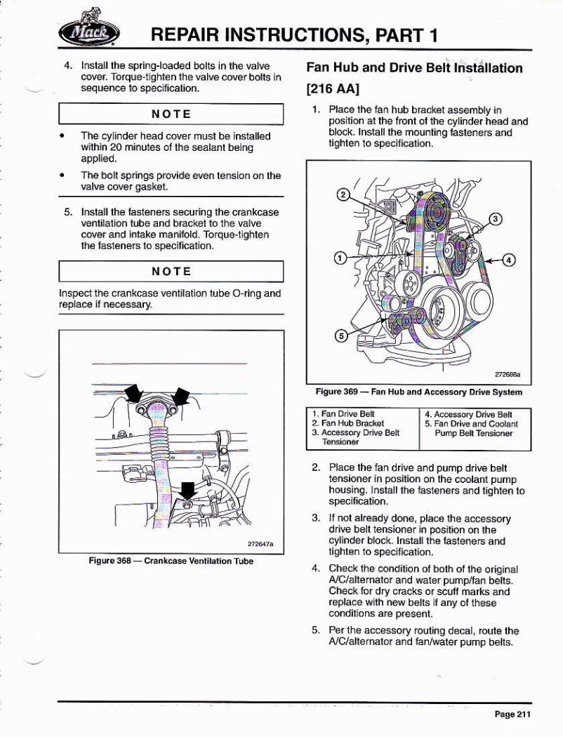
3. lnslall lhe bolls lo secufe lh6 wiing hafness
Cylinder Head (Valve) Cover r
lnslallation
[211 JBI1. C ean lhé g6két sáaling sllace ol lhe
cylhder héad. The su¡la@s shóuld bó cléárof a¡y di¡l or debrls and l¡ee ol any oil.
2. lnspecl lhe gaskel lof damage. li@pla€mént is necéssary caEtully plácá añe gdk6t intó the channel, ñákiño suélhat I ¡s propeny *aled and tollds lhe@nrour of rhé chanñé|.
FlguEscyn.&fH*dcov¿lG'3k¿t
3. Appry a 2 mm i0.079 ¡nch) bead of MAoKséalanliolh¿ areawhere lhe liming @verándlhecylinderhoad mééi. This paning linéis on bolh s¡des of the cyli¡der héád.Ca€lully posilion lhe valve cover on thecylindsr h6ad and make su€ lhal lhe sealrema¡ns pope y séátéd.
5.
Cónnecl thé vanous le¡mináls as lagged aldi*ssembly lo áll ssnso6, rslays áñdcomponenls such as ihe stailef, allernalofand Élli96€nl cómprcssrámong olhé6.
Anach rh€ clamps lo hold lhe hamess on lhe
REPAIR INSTRUCTIONS, PART 1
NOTE
4. lñstálllhé sp ngloaded bolts ¡n lhe utvecovei Tofqúe tlqhloñ lha @l€ cover bolts insequen@ io speoilication.
The cyl¡nder head cdór musl b€ in$anedwilhin 20 mi¡utes ol lhe séálánl beinq
The boll springs pov¡de e@n te¡sion on lhé
5. lnsla¡llh€ last€néB securino lhe c@nkcsevenl¡bnon tube and bÉcket lo the vd@cover and inlake manitold. Torquerlghlenlh€ fásl€néc lo specilicalion.
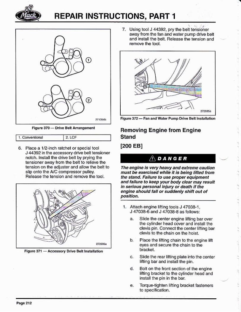
Fan Hub and Drive Beli lnstállation
[216 AAI1. Pla@ lhe iáñ hub bráckét a$embly ¡n
pos lion al lhe f@nl of ihe cylind$ héad andblock. lnslalllhé mounting tasleneG andlighleó 10 sp4jfi calion.
t1&€soryod€BdI Puñe Bor' rssiomf
Pláce lhe 1áñ d ve and puñp driw behlens¡oneriñ posirion on lhe coohfn pumphousing. lnslatt lh6 tasleners and l¡qhten ló
ll nor ¿keády done, pt¿c6 rhe a@essorydrire bsll i€nsioner m pGrlonon th6cylindef block. lnsralllhe l4te¡e6 and
Check lhe @nd¡llóñ of borh of rhé óridi¡srA/c/áltemalor a¡d waier pumpÍan belrs.Check tor dry cEcks or scuf marks ánd@Place wilh nd b€lls I ány ol these
P€rlhe ac@$ory rouling d8cal, bure lhe¡Llo/alterñalo¡ and lan/water pump betts.
NOTE
l¡spetthecEnkcase ventllatión lubóOjing and
REPAIR INSTRUCTIONS, PART 1
7. Using lool J /14392, pry lhe be¡l lens¡onereay fom ihe ran and wátér pump dnw behand insralllhe belt. Reléass lh€ lénsion and
Removing Engine ftom Eng¡neSland
t200 EBI6. Place a 1/2-¡nch Elchel or speclal loolJ4€92inlhéa@essoryd vebelllánsionérnolch. lñs1álllh6 dfive belt by pryiñ0lhelenslonef away fom lhe bell lo €li4e lhelénsion on lhé adiúste! ánd állow thé bélt losrip ó¡io ihe ¡l/c @npfes$r purréy.Feleaé the léñsion and r¿move lhe tod .
fhe qglre ls very heaw an.¡ at@e úuüúñwr he exnise.l whíle ¡t is belng úfted lrcnthe stan !. Faitut¿ to u* pñpü éqlipúentaDd ,allure to keep yoú bo.,y ct@t ñay re ttin e¡iffi p*@I ¡n¡ury ot.l@th ÍtEúgíre shoúLt la d s¡r.rdúly ah¡ft out of
1. Atach engine lifung ioo s J 47033-1,J 47033-6 and J 4703a4 as lottows:
a. S idé lhé centerengine liftiñq barderthé cylind€r head cwerard instal lhecl4is pin. Connect thé c€nlé¡ lifiing barclévis lo lhe chain on lhe hoisl.
b Placelhe l¡fing cha¡n toihe é¡giná tiftey€s ánd s*ure lhe chain lo th6
c. Sl¡de thé réár lifting plare inlo the @nterlifting bar and iñslalllh6 pin.
d, goll on lhe floñt sectioñ ol lh€ 6ng nelifting bBckel lo lhe cyl¡nde¡ héád áñdinstallth6 pin in lhe bai
é. Torqué'lighlen litt ng bracket hslene6
REPAIB INSTRUCTIONS, PART 1
U* on¡y the ch¿¡ns, ctév¡B dnd tiking pla¿eprov¡ded wilh th* spec¡al tals. Fail* Ioúé ¡hé @ret sp@lal too¡ @nponents náy¿Iów lhé úg¡re to fa, @u.¡ng 4 @5pet@nal ln¡úry ú rlééth.
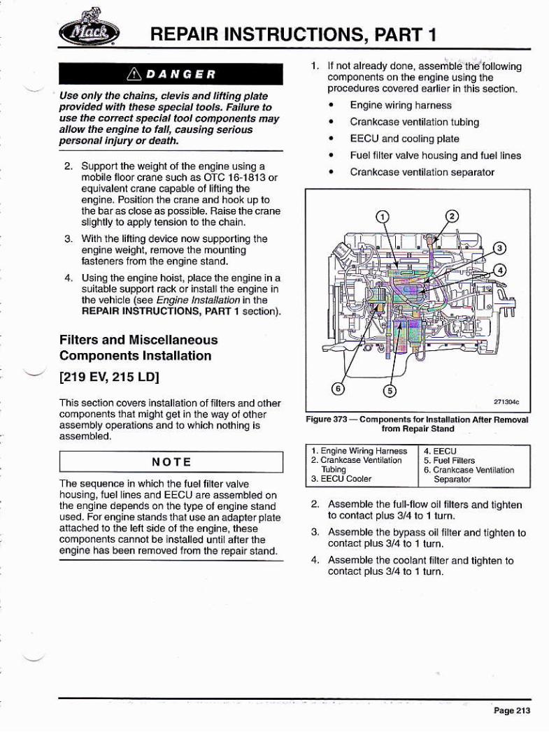
1. r nól ak€ady don e, asser; blé thd lottowjnsoompo¡enls onlh6 éngine using lhep ocedu fes cove red ea i6r in this 6eclion.. Enginewkins harné*I cfa¡kcase ventilát on lubing. EEC|Jandcoolinqplal6
3.
F¡lters and MiscellaneousComponents lnstallation
[219 EV,2t5 LDI
This seclion coveG lnslallation ol lill6B ánd olhércomponenls thar might gel in lhe way 01 olhera$embly opéaiions and to which nólhing is
NOfE
Fuel l¡lter valve hóusing and luéllines
Cra.kcase venlilalion sepa€lor
i . Eno n6 w?iñq Hamess I 4. EECU
I 6.CankasvéñúárónI s+¿mbr
2. Assem ble thé fu ll-llów oil tilte 6 and tig ht€nlo .onlacl Plus 3L/4lo I lurn.
3. Assemblelhe bypasso nleránd Ughtenlocontácr plus 3/4 lo 1 lurñ.
assémble lhe coolanl flteránd tghren 10contáó1Plus 3/4 lo 1 lurn.
Supportlheweighl of th6 én9in6 usinq amobile ll@rcEnesuch as OfC 16.1313 orequivalentcrane capable ot lifing lhe€ngi¡é. Posilion th6 cEné and hook up lóthe bar as d6e as pos ble. Baiso lhe cnnoslighrly ro apply rension rolhe chain.
With the lifting device now suppo ing rhe€ngi¡e w€ight, @mov€ the mou¡lingfasleneBlrom the enq¡ne stánd.
Using theenlhe hoisl, pla@ lhe engine in asuitable supporr Éck or insiall rhe engine i¡lhe @hicle (sée F¿o,h€ /rs¿tlrli¿, in lheREPATR TNSTFUCIIONS, PART 1 secrion).
Ths sequ6nc¿ in which the luell¡ller hl@housing, tuell¡nesá.d EECU ဠssembled onlh6 ¿nq né dépendsoñ the lype ól6nQiné slandu@d. Fof engin€ slands thal use an adapler p atéattached lo lhe len s¡dé of lh6 ánginé, rhesecóñpoñ6¡ls cannol be ¡nslalled uñti aft€flheengine h6 b$n fomoved t@m lhe repa¡¡ siand.
REPAIR INSTRUCTIONS, PART 1
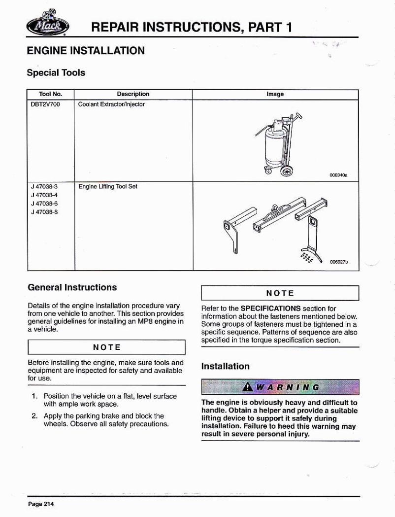
ENGINE INSTALLATION
Special Tools
General lnstructions
Détails oi rhé enqine insla lalion p.océdue Erylfom one Éhicle to snolier This setioñ prdidosgene@l guidelin6 Jor insralling an MPB enqine in
NOfE
NOTE
Belore insiafing lhe enqin6, mak8 su€equipme¡t a@ inspecred lor sfety and
R6rer to th€ SPECIFICATIONS section lorlnirfrá¡oñ ¿boll lhe laslénéB mé.lioned be ouSome groups ot
'aslene6 musl be tlqhtened in a
sp€cilc sequence, Paflens ol sequence are alsospeciñed i¡ the lorquo sp€cili@tion seclion,
lnsrallation
Thé engine ¡3 obv¡ously heavy and difñcult lohandle. Obta¡n a helper and prd¡de a súitablel¡ftlng devlce to support il salély duringiBrállátion- FailüE to hedthis r¿rniñg ñáyesú ir séveÉ p€bonal ¡njury
1. Positlon the vehiclo 0n a fat, lwel 6u.lace
Apply lhe parklng brako añd block ihewheels.Obse@allsatelypreautións.
REPAIR INSTRUCTIONS, PART 1
^caurroN
3,
Ensurc aI bofts a'.t üns arc @récüyposl one.r priot to rñoúng thé úg¡re hoñthe eng¡ne stú.1, Fallwe to propúly lnaan anbóIts ¿nd píre ól lhé éng¡n. lifting tool enrcsult ¡n petsorat ínjury .ltor dédh.
4. Usinq lhé €ngine iiftinglool, J 47034, andwlih lhe ald of the helper, lifi and lower lhé
Alig n lhé áng i¡e wilh lhe I ransm¡sslo n.
lnslalland, using a toque wEnch, tiqhtenlhe rear engine suppon aftaching screwsamo dinq 1o s pe.ll¡catlo n.
lnslall and, u6¡ng a loque we¡ch, lighlenlhe lóñt enqin6 suppó aiaching scr4a@ofding 10 specllication
Femo@lhe engine litl¡.o lool lrcm lhé
L App y án évén 2 mm (t64 inch) bead ots€lantátlhe joinr lines between thecyli¡der head a¡d tholiming óEr,
¡stalllhe va@ 6v€r wilhin 20 minules oi
hsral lhe rEnsmr$ron ahd, u]eind a lorquew¡ench, 1 ghlen the l€nsmissiú áltachingscrews ácerding 10 specilicalion,
Wlhdaw lh6 lEnsmission jack.
a. lf hañual lE nsm iss io n. atlach lhe. uich linkage añd bfacker Gia¡ñing
b, lf aulomatic fansmission, attach ihetofque conrener accéss pan€l and
Aflach the h@d esl crossmember ll
Co¡nect slartBr wnes and cables,
Attach thé peérsiée ng hoses and
AIlach lhe exhausl syslem braókels.
Aliach lhe exhaust syslém lo lhe
The rád¡álor and CAC ásseFbly ls hdy andd¡fi¡culllo handle, Prcvidé á su¡tablé lifiingdev¡e á¡d á hélpér lo supporlltsalelydur¡nglnslallation, Failuré to héed this waming mayEsult in severc Dersonal ¡n¡ury.
Anach ihe adialor and CAC 6sembly.
1
wh¡lé i.sratl¡ng the engke, wat h lot abstucl¡úslhal ñay ktañée. such ae eng¡ne and chassÉ@rnpúeñl' bhcke.ls, clanps and other pañsa¡tached to the lqñe and @b. Fá¡lurc to heetl¡h¡B 6úim n6y Esult in sevee danage to ¡he
ghe aúl other @pú4ts.
Cryérlhé valvé méchanism and géarlÉinwlh a suitable clolh or simlaf covedng 10p@enl di¡l and debris lom enleing lhe
Aiach the €ngina lifting tool, J 47034, lo ñee ñOine. Secure lhe enq lne llftlng tool to lheircnl ol rhe cylinder head and ro lhe rear althelywh6el housinq. Adlusllhá1oo to
12.
15.
17.
5.19.
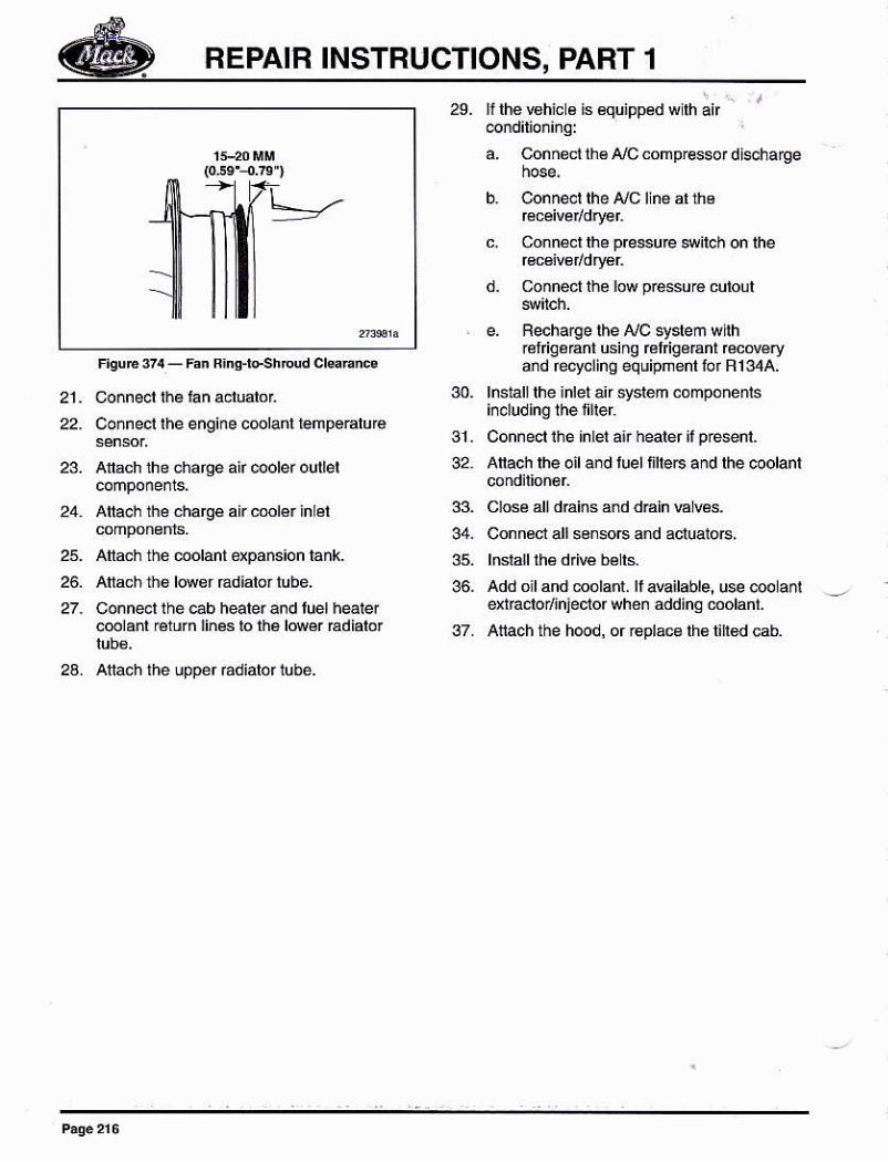
N OTE
To all@ Jór chssis anlculatlon in s6ver6 serviceappllcatlohs, tho lan ing rubbefsea doés notlililush agai¡st1he shroud on cU modetchass¡s. Aqap of 15-20 mm (0.59 4.79 iñch) dislsbelween the fonl lacé ot the aluminuñ tan nng blhé back lacé óf lhé rán sh.ó'
'd
NOTE
10. lnslá lrhé varvé cóvér
BEPAIB INSTBUCTIONS, PART 1
29. IttheBhicLs is €qu¡pped wlh;ú " r
@nd¡lio¡¡.9:
a. Conñ€ct lh€ ¡/C comprGso¡ di$harge
h conner rhe ¡Jc ln6 al tho
c. Connel lhe p@ssu@ s¡l6h on lhe
d. coñn6ct ih6low présuÉ cutour
e, Recharqe lhe NC syreñ wnhréfigéErn usiñg cl gérant rccd6rydd recycling equipñenl for R134A.
30. lnstall lhe ¡nlei a¡r system componénls
31. Connecl lhe ¡nlel a.r healer ¡, p€senl.
32. Atach lhe oil and tuel t¡lle6 and lhe coolanl
33. Closé all dhins ánd dain Elwa04. Connect all so¡so6 a¡d acluatoB,
36- Add oil and molant. lf aEilable, use @dalqtEclor¡njeclorwhen add¡nq óolánt.
37. Atiach the h@d, or Épla@ lhá lih€d cab.
21- Co.necl üE fan aclualor
22. Connecl lhe engine c@lanl lemp€@luré
23. All5ch the chafge air @oler oullel
24. Atach the charge air cmlér inlél
25. Aia.h thé dolant dpanslon lank.
26. Anach ihs l@sr Édiálor lube.
27. Conn4l the eb h@ler and luel heáerc@lanl €rurn lines ¡o rhá ld6r Ediaror
24. atlach ihé úpper radlalor lubé.
REPAIR INSTRUCTIONS, PART 2
REPAIR INSTRUCTIONS, PART 2
rN-cHASSTSPART/COMPONENTPROCEDURES
This séclion pÉsenls slandalone rcplacemenlopeálions wh¡ch €n bé doñé in chasis withóúa comprere enqlne @fhau¡. The* ope€rions
. CAMSHAFÍgEAFINGBFACKETS,BEPLACEMENT
. OIL fHEBMOSTAT ANO PFESSURESAFETY VALVE BEPLACE¡¡ENÍ
. CFANKSHAFT FBOÑT SEAL
! CRANKSHAFT BEARSEA!
. CBANKCASE VENIIIAfION {CCV)SEPAFATOF REPLACEI¡ ENT
. OIL PUMP REPLACE¡'ENT
. INJECTORCOPPERSLEEVE
. UNIfINJECfOFCLEANING
. VALVÉ STEM HEIGHT MEASUFEMENT
. VALVE STEM SEAL REPLACEMENT
Du€lólháEngine Eléctronic Codról Uni (EECo)sell lear¡iñg capability, il is nsBssary lo €s€llearned EECU pa€melers atlerseruic¡ng some€nainé{élá16d componénis, This állNslheEECU lo leañ lhe new conponsnts béháviorAfter sedl.inq is comp ele, pefom lhe 'Leamed
CAMSHAFT BEARINGBRACKETS, REPLACEMENT(MACK MP8 ENGINE)[2r3 CJ]
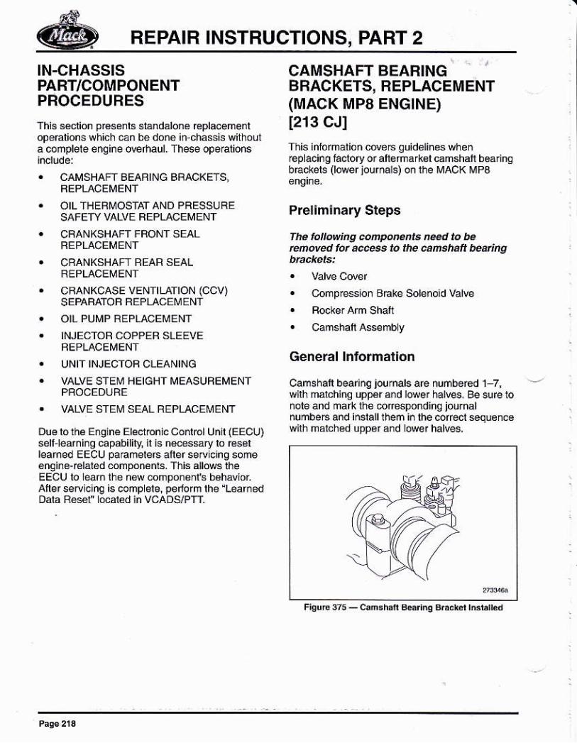
This inlorñátióñ cdé6 guidélinés wheñ€placing iaclory or aferñárkél camshalr báárinobEckets (lMr jourñals) on ihe MAoK MPB
Preliminary Steps
fh. lóllówing eñFótunts m¿d lo b.retuved ¡ú a@ss to the @ñ.haft bñing
' CompEsion BEke Solenoid Valve
t Camshaft Assembly
General lntormallon
Cams hatl bearinq jou rnals are nuñbered 1 7,wilh malchina uppér and lower halves. Ae sure 10nole and mark the 6resp¡ndino iournalnumbeF and insralllhem i¡ rhe cofecr *quén6wirh marchéd uppérand lwer halves,
REPAIB INSTRUCTIONS, PART 2
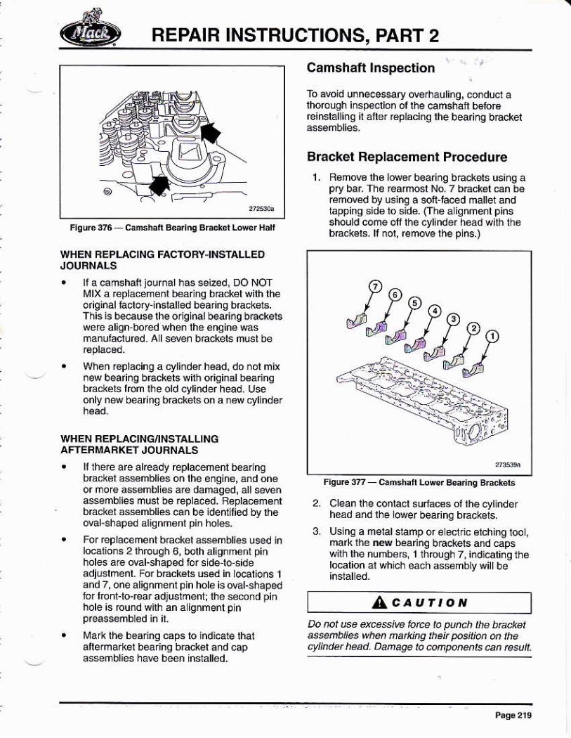
F¡gUl¿3ñfubñB¿'ngBrcchlL¡krHátr
WHEN BEPLACING FACTOBYINSIALLEDJOUFNALS. rt a camshaf jourñar has se¡zed, Do NoT
túlx á r€plácaménl báaring bEckél wirh rh6o rig lnal laclory-inslalred bearinO brack€rs.This is bsause lhe o¡iqinal bearing b€ckelswere alion bored whe¡ lhé 6ñ0iné wásmanutacluEd. A lsden bEckels must be
. Wheñ réptácing a cylindér héád. do nol mix¡4 bearing b6ckelswith original b€ánngbEckers |lom lhe old cytinder head. Useonlv new beá n0 bÉckéls on a néw cvlinder
WHEN REPLACING¡NSTALLINGAFTERMARXEfJOURNALS. ll the@ are aleady repla@nént b€arlng
bEcksl assmblies on the eng¡né, a¡d on€or ñore ass€mblies áre damaged¡ all s*n4senblies nusl be eplaced. Raplac€ménrbackét assmblies can be ¡defillied by lh6dal-shaped aliqnm6ff pin holes,
. For replacement báck6l assmblies usd lnlo€lions 2lhrough 6, both alignm6rf pinholes ar6 oval-shaped iof sideles¡deadjushenl. For bdckéls used in lo@lions 1and 7, onealiqnméntpin hol6 is oval-shapedfor l@nr-lo{ear adjushert ihe se6nd piñhole is ound wirh an á ignmenl pln
lüárk thé boaring caps lo lndi€le lhalallermaiket beáing back6t and capássémblies haE béén in$ánéd
Camshaft lnsp€ction
To arcid u¡neoe$ary derhaúti.o, co¡duct alhoroogh iñsp€clio¡ ol lhe camshait b€for€feinsralling áner fépracing lhe beafing báckei
Brackel Replacement ProcedureL Bemow lh€ lower bea¡inq b€.kets us¡ng a
pry bar The rearnosl Nó 7 b€ckál €n béBnded by usinq a soft-hced manet andtapping sid€ lo sidé. Crhealignmenl pinsshould come oll the cyl¡nder héád with lhóbEc*érs. lr ¡or, remove the pins.)
2. Clean lhe conlact sulacés of rhe oylinderhóád and lhe l@e¡ béa ng bráckets.
3. Usinq a meiatstamp or e édric éiching tool,mark thé ñ4 beanng b€ckeis and capswilh lhe nuñb6rs, 1 th@ugh 7, ¡¡dlcaliñg theloclion ¿r whch eách ¿ssémblywilrbe
^caurtoNDo not e dces¡@ lc@ la pnch lhe ba.kerasñü$ whú ñatk¡ng rheit p6il¡an on thectündet had. Dañage lo úrponenE ca, resu¡¡.
REPAIB INSTBUCTIONS, PART 2
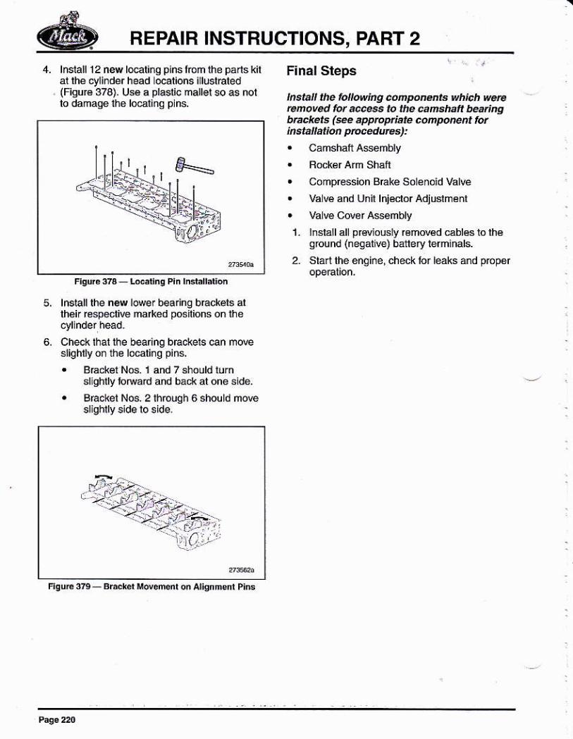
lnslall 12 nM l@liro plns lóh the p¿¡ls kilar rhe ctlinder head ocalions illuslhled(Fisur6 378). U€é a plasüc mallel so as nolto dahaÍe the lomlina plns.
F¡nal Sleps
lnstall ihe followíig cñpóNnta which @rercmoved fot @s to lhe añshak beaúngbttukets (eé dppto4iate cmporent lorinsbnatun ptuédrcs):! Camshaft Asambly
r Compbssion Braké Sol€noid VaN€
r Va w and Unn lniéclor Adiushénr. Va vé Cd¿r A$6mbly
1. lnsiall all prdiously rémowd €blés to lh6qbund (negatrve) báttery temrñars.
2. Stárl lhe énoine, check lo¡ léáks áñd pópór
5,
6.
lnsrallrhe new lower bea ng brackels allhei €spocliw marked positions on ihe
Chec* lhal lhe bearing bEckels can m@s¡iqhly on the localing pins.
. B€ckér Nos. 1 and 7 shoub rurnsllghlly lodard ahd bad< at one side.
. Braoket N6. 2 fióuSh 6 should ñove
BEPAIR INSTRUCTIONS, PABT 2
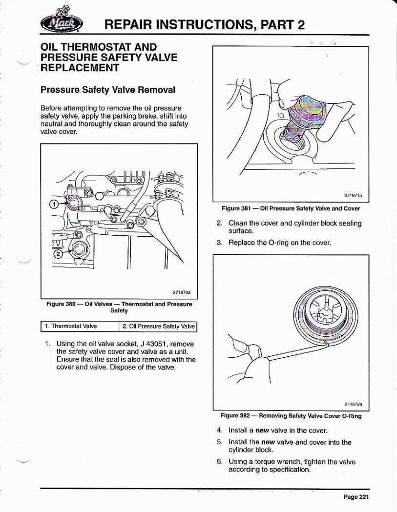
OIL THERMOSTAT ANDPRESSURE SAFEW VALVEREPLACEMENT
Pressure Safety Valve Removal
Belo¡e aliehpthg to rehde lh6 oil pbssurésalely El@, apply the parkirg báké, shifi ido¡ellaland ¡horoughly d@n arcund lhe salely
2'olP'sUes¿felyv¿b
1. Us¡ng tho o Ivdw sekel J43051,remdelhe salély klve úer and wlv6 as a uni.Ensuré lhal lhe seal is de remowd wilh thacover and É¡w. Dispose ol lhe valre.
FiguÉ331_oilPresuEs¿le¡ybfudbd
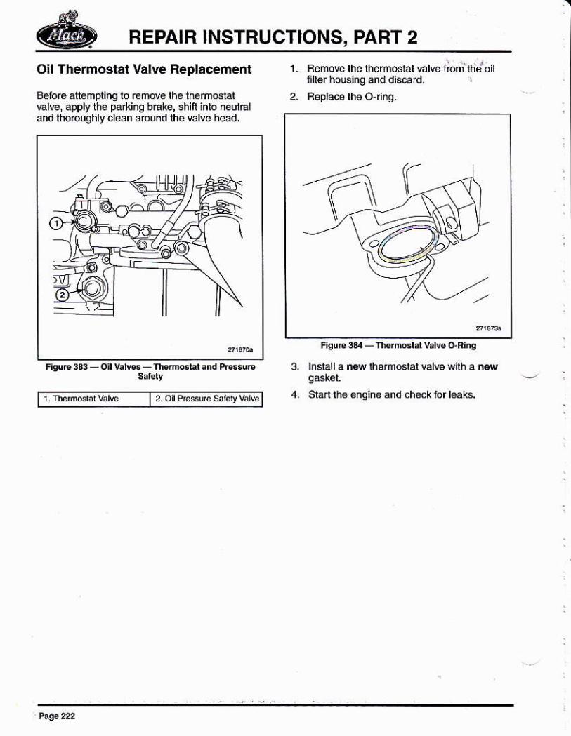
2. Clen ihe cder and cll ndét block s@ling
3. Fepl&e lhe O-ihq on the 6€L
'iguE3P-nemd¡ngs.l.lyva¡wcdeldn¡ng4. lnsl¿l a n4 valve ¡n lhe cder5. lnslal the new Elve and tur inlo lhé
6. Usiñg a lDrqué w€nch, lighlen lhe valveac@¡dino to sDécilicalion.
BEPAIR INSTRUCTIONS, PART 2
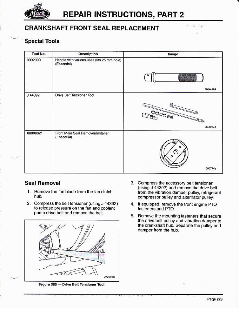
Oil Thermostat Valve Replaceñent
Beloé allempling lo rende the theftuslatvalve, apply the parking b6ke, shift ¡nlo ne{nÉ¡and lhoouqhly clean aDU¡d rhé válve head.
2,
1. Femow rhe rhem6rá1 Éúe norith.i oirtille. housing and diserd,
¡¡srall a nM rhé.moslat vdw wnh a ¡éw
Slart the engine ahd check lor loaks.| 2.orPrc!&€s¿htv¿E
3,
REPAIR INSTRUCTIONS, PART 2
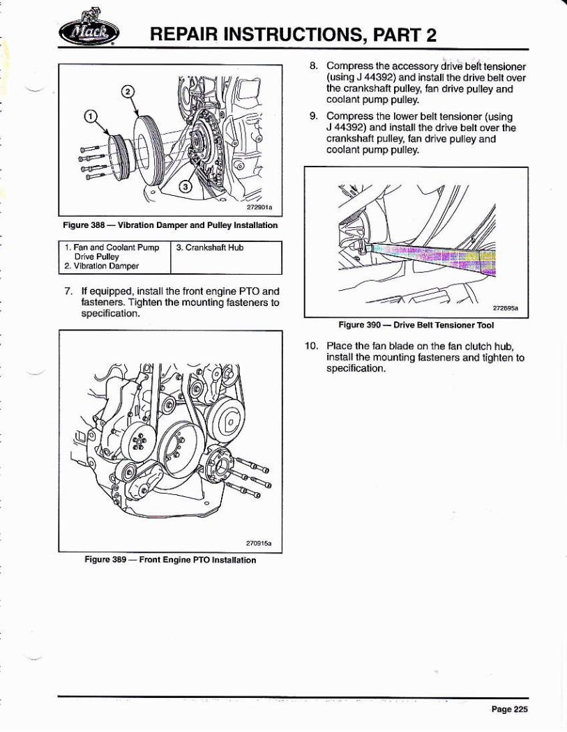
CRANKSHAFT FRONT SEAL REPLACEMENT
Spec¡al Tools
Handls D h Erious u*s (rb 25 mm hob)
Seal Removal
1 , Femove lhe fan b ade fóñ lh6 lan clulch
2. Comp@ss rhe berr re ns¡o ne r (u shg J 44392)io éleáse pr6ssu€ on lhé fáñ and @olanlpump dd@ belland remow th6 b€lt.
Comp¡4s lh6 accessry belt lensioner(lsing J 44392)and rem@ lhé d ve beLllrcm rhá vibBlion damper puttey, r6f'iqe€rfcompfessof pulley ard alternalor pulley.
lf equipp€d, rcmove lhe font engina PfO
Femove ihe mounring lasleneF thal secufslhé drjve bell pulley and übralion damper 1olh€ cr¿ntshafi hub. Sep¡raF rh€ pulléy ánd

REPAIR INSTRUCTIONS, PART 2
Seal lnslallallon1. Clean lhe seal sealing surbce ¡ñ the
cáñkshalt lrcnl cowr ánd lhe sealingsuface ol the cfánkshalt hub.
2. A$emblé thé handl6 (9992000) and lbnlmai¡ seal removerlnslálLer (33300021).
3. Place a ¡ew c€nkshail flonl seal on thecÉnkshatlfbnl seal rémowr¡nslallé.
NOfEThe cankshaft lront sۇl
/AcaurroNWhen handlkg a v¡bñnú danper be @@tut notro damgÉ tha housing. Dals k lhe óútdhoB¡ñg ún rcndet the danpet ireíect¡@. t¡dafuged, the viúa¡ion danper @nnat berepaired and ñBl be rcPlá@d.
l 3 cEnk hdfi fub 4, Posilion lhe cankshatl fronl seal
cEnkshalt húb ánd cEnkshaf font cowrCareiully dri@ the seal i¡lo lhe @rer unlillhé lool bonoms agáinsl thé cankshaft hub
Femove the looland nspecl th6 seallomaké surá lhai i! is pfopefly i.staLled.
Pl@e lhe vibalion damper and lan pulley onthe crankshái hub and áiiqn lhe tuslenerho es. lnlalland Íghl€n rtu mounünalalene6ln fivo sleps lo specf¡cat¡on.
NOTE
6. Fem@ lhe 6rank6haft seal as tollowsl
A, D lrl@ 3.5 mm (0.138 inch) holes inlhe ñetal rim ól thé cr¿nkshalt llo¡[email protected] lhe holes in the im ol lhelmnt main s€L rémoEr¡nslaller(33300021)ásaaulde.
Using rwo solhappi¡g M5 screws olsu¡lable lengt\ anách lhe dánkshanl@nl 6ea¡ removetiñslal er lo lhe seal.
using Nvo M 10 iasleneB ihfeaded lnto
r6mMr¡nsraller, remrye lhe
Apply grease on lhe end ol the dnl bil ró pr*nlchips lom geflinq i¡lo lhe enqi¡e,
c,
REPAIR INSTRUCTIONS, PART 2
Pulbylñd,úálioñ
9.
c¡mp@s6 lile ac@s$ry ¿íü bei rensioner(úsino J ,14392) and insian fié driv6 bé[ @rlhe cánkshalt pulléy tan d ve pu lley and
Conpress the lower béll lénsioner lusingJ 44:192) od install the d¡iv6 boft Ner thecáñkshaft pulley, lan drl@ pulley áñd
Fhu6 3e0 - Dnw Bd rsn6roner ftor
l3 c'alshafi Hub
7. ll equapped, ¡nstalllhefasléne6. Tighlen lhe
REPAIR INSTRUCTIONS, PART 2
CBANKSHAFT NEAR SEAL FEPLACEMENT
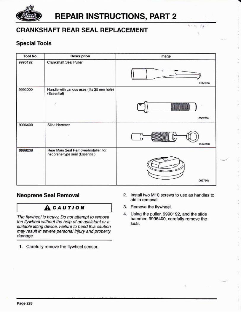
Special Tools
Handre *irh vai s usas {fib 25 ññ horo)
náopÉno tvpa si (Esnrian
Neoprene Seal Removal
/Acau¡toNThe wh@l É lEaw Do nc,t atén1pt to Enovethe twh@l wjthtut ¡lE heb of an ass¡staht ú asu¡ta é ifl¡ng devi@. Íeitue t heed Lk¡s @ut¡úñaY @tt k @vde P*tut kiuty éñd uapeñy
1. C¿ Elu ly rem@ lhe llywheel senso(
2. lnslall lwo M10 screws to use as handl6s lo
3. F€more lhe llyryheel.
4. U6inglhepuler,9990192, and the st¡déhañmér, 9s96400. caE u0y rem@ the
REPA]R INSTRUCTIONS, PABT 2
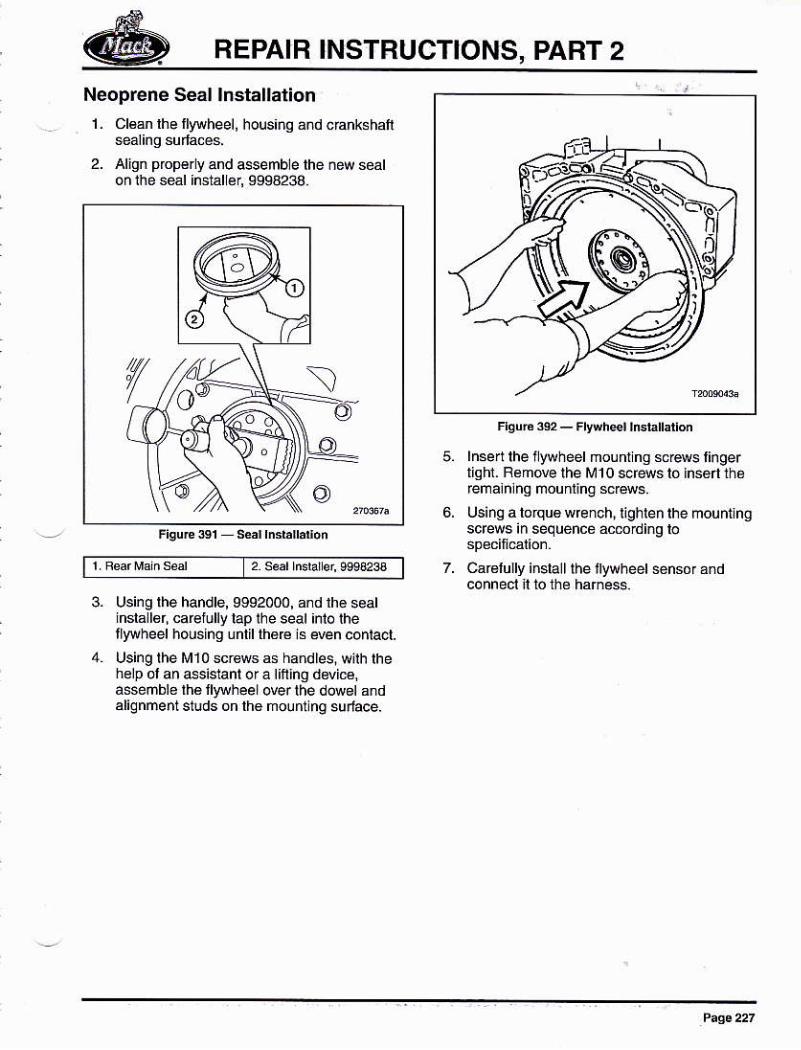
Neoprene Seal lnstallationL CI€án lhe llywheel, hous¡ng ánd c€ñkshaf
2. Align prop€rly and 4semble lhe ñew sealon ihe s€l hstál ér, S998238 N}
Freun @- Fwhé.t ttuhnad
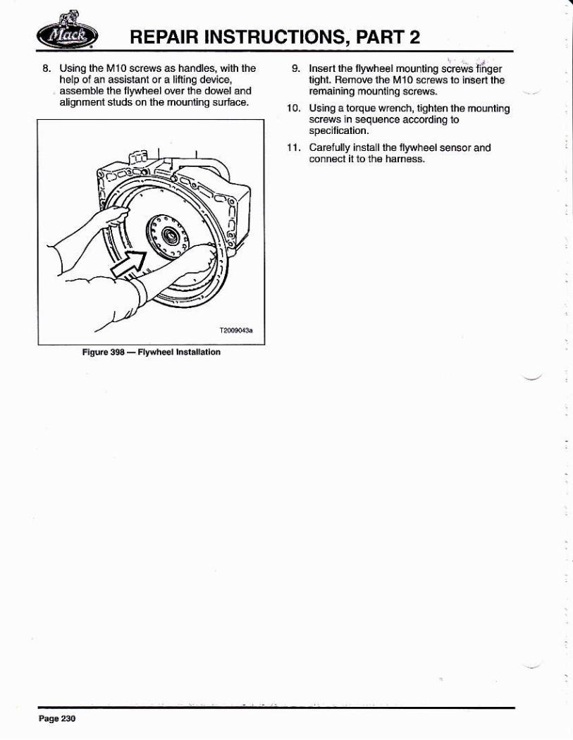
lnsert lhe llyoheel mouff ns sc@s lingerlighr. R¿move lhe M10 scfss ló hsért théremálnlnq ñounting sr4s.using a tofqu€ w@¡chi i¡ghlen lhe moufthgscEws in sequenc6 acddiñg lo
Ca€lully inslallthe llywheet s6nsór ándconnecl n lo thé hañess
5.
3. using lhe handle, 9992000, and lhé sealinslallgr, ca@tully lap the seat ¡nto thetlywheel houshg uñtil th6€ is @n contact.
Using lhe M10 scrows as ha¡dles, w¡lh thehelp ol an Gsistant o¡ a tnhg ddiE,asseñble lhé fyryheel o@r the d@d a¡dalignnent sluds on lh6 mount ng su¡face.
REPAIR INSTRUCTIONS, PART 2
Teflon@ Séal Removal
^caurtoNIhé whed ¡s hav/. Do tul atteñpl lo etuvetE flywheel wlhaut the help ol añ a*idant ü asuitane tilt¡ng dqi@, Fa¡|u@ to h@d ¡h¡s autiúnay rcsult ¡n sevqe pe6úa1 kjLty and ptapérly
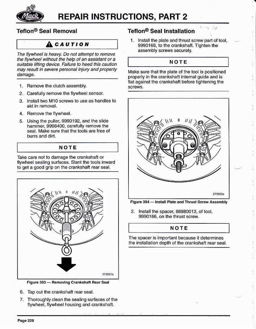
Tetlon@ Seal lnstallation1- lnsialllhé platé ánd lhrust sw pa oll@1,
9990166, ro rhe c6nkshalt. fiohign lh€4sembry sc@ws *cu€ly,
firake suB lbal lhe plale ol the looL is pGilionedpropo y in lhé c€nkshal inl6rnalgu dé and isnát aga¡nsl the c€nkshall belbfe lighiening lhe
NOfE
3,
5.
NOfE
L Remwe lh6 clulch Gsénbly2. Ca@fuly rámoB lhé llywheel señsr
¡¡stall t¡lo M1O scr6m lo úse as handl€ lo
Usingi¡e puller, S9S0192, and the s¡idehaññer, 9996400, É€lully rémow lheseal. Mak€ su¡é thal the tools are lee ol
fap oul lh€ cEnkshalt €ar sal.Thorcughly cláan lhá séaling sudaes oJ thénylvhBel, flwh€al housinq and cÉnkshaft.
lscldA$¿mbly
2. lnslall the spa@r. a8aaofi 3. ot toot.9S90166, on lhé rhru6t screw.
fake cae not lo damagé lhé cEnkshan orllywhéal soáling súrf¿ces. Slant the tools inMrdlo gel a qood grip on the c€nkshall rear 6eal.
NOTE
Ths spac€r is imponad beause il delerm¡neslhe ¡nstallalion deplh ol lhe c€nkshaf @ar seal.
6.
7.
REPAIR INSTRUCTIONS, PABT 2
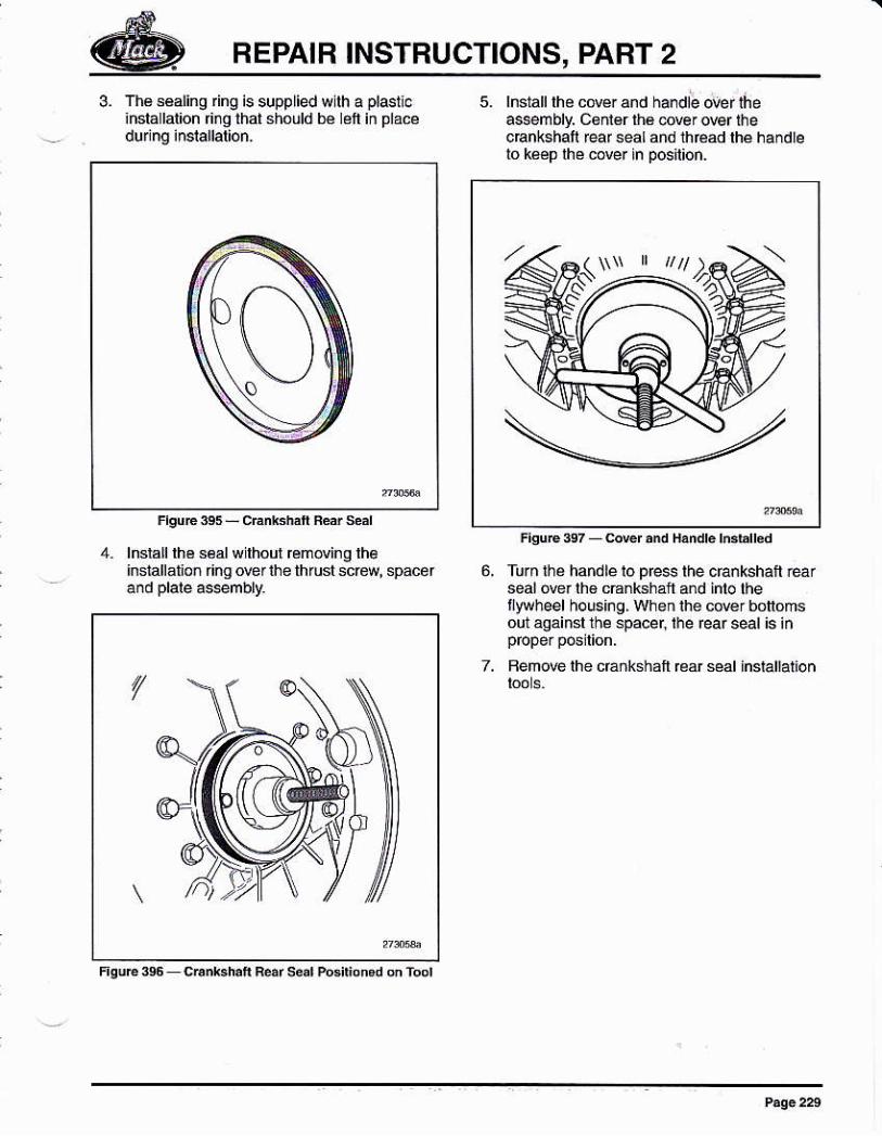
3. Th8séaling ng is supplied wllh a¡nsla lalion ¡g that shóuld bé eft
5. hstall fté cowr and ha¡dle o@r úeassembly. cénl€r rhá c@¡ oEr hecBnkshaf feaf seal and thféád lhe handleló kép lhé cover in pos¡lion.
4. lnsralllhéséalwlhourrcmovingrh€installato¡ ring o@¡ lhe thrusl sc€w, speór 6, Turn ih¿ handle lo pre$ lhe crankshail Éar
seal óver lh6 c€nkshal úd inlo lhel¡ruheel hous¡ng, when ihe cdér bonomsod áqáinsl the .pacer, the rear s€l ts in
7. Bem@ lhe c6ñkshall €ar séal installation
/
REPAIB INSTRUCTIONS, PART 2
\+7N\
^
F¡Ñf.sss_Fl9$li*l|rel.lljlon
lnséri rh€ nywh€elmou¡ting rcreB lthqerl¡qhl. Rémow ihe Mlo *Éws lo inse theemaining mouñllng sctu.úsing a lorque w¡ench, llqhtén thé nounri.ge@E in *quence a@od¡no 10
1 1 , caÉfully in€lall i¡e llywheel sen$r and
REPAIR INSTRUCTIONS, PABT 2
CRANKCASE VENTILATION(ccv) SEPARATORREPLACEMENT
CCV Separalor Removal
1. D¡sennect thé batt€ries, or iurn of lhé main
2- Clean the cyliñder block afound lh€ ccvsepaÉlo¡ mounli¡g.
Remow the ccv sepaátor foñ the
CCV Separalor lnstallation '1, Clean the mounlingsudaces on th6 cytinder
block and lhe CCV sápaGloi2. Using a re gaskél, assémble the CCV
sepaElor on lhe cy inder block.
3. Usinq alorque wrehch, tighten thé screwsamording 10 6peclical¡on.
4. Anach r,há CCV hoses.
5. Turn on lha main swit6h, or r@nnect thé
6. Slart the enline and chdk for leaks.3_
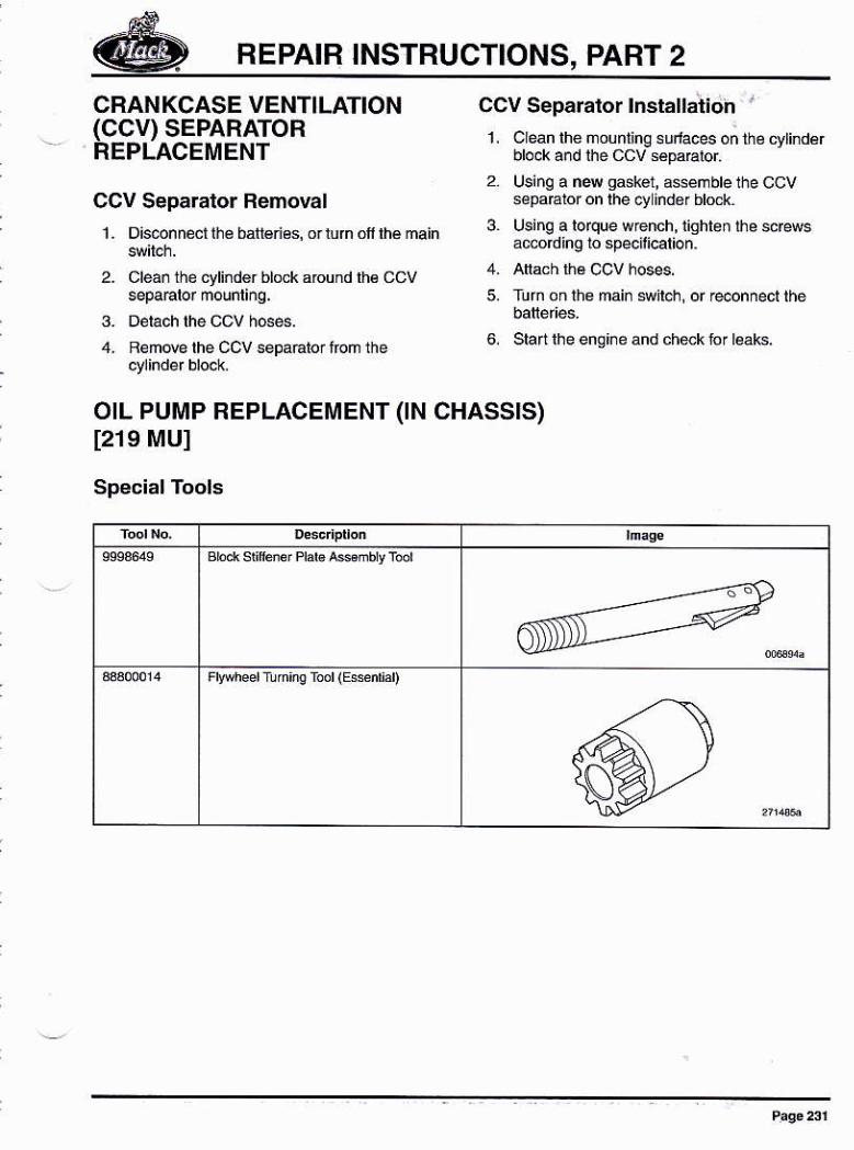
OIL PUMP REPLACEMENT (IN CHASSIS)t219 MUI
Special Tools
FrpheelTunie roor (Bsén¡aD
REPAIB INSTRUCTIONS, PART 2
311oO
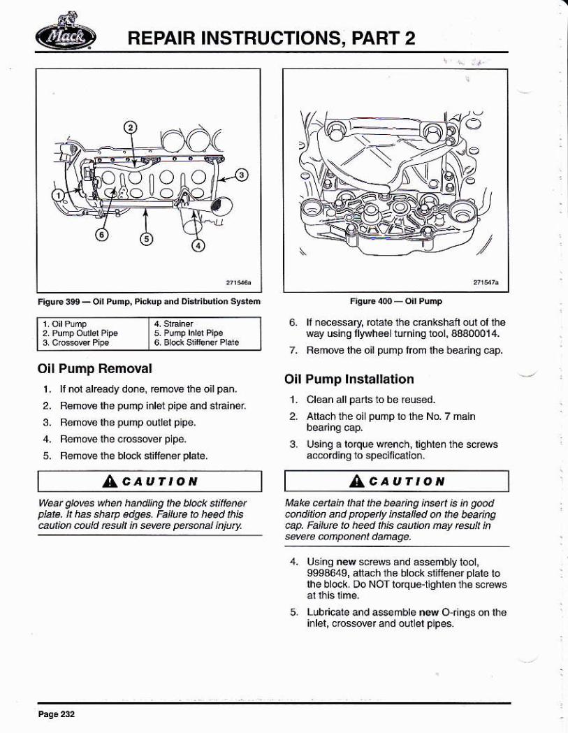
i#btlionsysl¿m
'7'\'\''
2PUmpodlelP'pe6. ll necessary, rctalé thé cBnkshan oul oi t¡¿
wáy usinq llywh€61 turning lool, aBa0O014.
7. Remove lhe oil pump lom lhé béárjna €p.
Oil Pump lnstallation1. Clean a[ pans b be ¡eúsed.
2. Atlach the oil puñp lo the No. 7 main
3. Usinq a lorque wrenoh, liqhten the scé6amordino to speciñcalio¡.
Oil Pump Removal1 . ll nol akeady done, remow tre oil pan.
2. R€mov€ the pump iñlet pipe and straiñer
3. Bemde lhe púhp outlet plpe.
4. Reñove lhe cbssder p pe.
5. Beñow lhe blod( st¡lle¡e¡ platé.
AcaurtoN AcauÍtoNWeat gloves whú hand¡ng ¡he úock st¡ienetplaté. h has .haP edg6. Faitu@ to heed th¡súu¡¡on @old Esúlt in sMre pe@ml ¡niurv.
Make cenak hat lhe b@ing ¡reeú ¡s ¡n g@dcohdinú and propely insfaled on the búing@p. Fai¡ue lo h*d ¡h¡s aut¡on nay esul ineverc mnp@eit dañage.
Using ¡€w scréws a¡d asseñbly 1oo¡,9994649, anach üé block slitlener plale lolhe block. Oo NOT lorque-1ighlBn the M@ws
Lub cale and 4semble na O nhgson lhei¡lát, crossowr and oul el pipes.
5.
REPAIB INSTRUCTIONS, PART 2
11.
a.
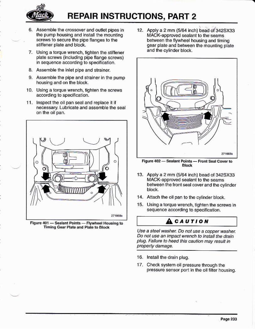
12. Apply a 2 mm t5/64 inch) bead ol342sx33¡rAcK-appoved seah¡n b lhá wmsbel@¡ lhe llywheel housing and timrnqgeaf plale ¿nd béhreen lhe mouni¡na p atéand lhe cyli¡der block.
Aseñbl6 lh¿ cro*@er and oullei p¡pes ¡nlhe pump housing ed instal ih¿ molnt¡ngscrcws ro secufe rhe plpe lranses lo lhe
Usiñg a lóqle wre¡ch, lighteñ thé slif6nérplalé *r€ws (incruding pipe llange scr&s)in sequence ác6ding to sp€cifi€tio¡.Ass€mbl6lhe inlel p pe and straineiAsémblálhe pipe and slEiner inlhe pumphousi¡g and on lh€ block.
Usi.g á loqu€ wrcnch, liqhlén lhe 6c@sá@ordlng to specil et on.
lnspecl thé oll pan séal ánd réplae il jlneéssary Lubricale and assemble thé sear
appry a 2 nm (164 ¡nch) bead or 342sx33¡,IACK appoved sealan¡ to thé *ámsbelw@n lhe lronl s65l 6ver ard the cyt¡ndér
attách lhé o¡l pa¡ to the cytindér btock,
Usingáloquewénch,nghlénrhesc@wslnseqúen¿o ádcódinq lospecilicalion.
AcaurtoNUse a s,leel washer Do rct use a úWet @sherDo not u@ an ¡npac¡ wrcnch lo insta rha da¡nplúq. Fa¡luÉ to h@d ¡h¡s @u¡ion nay resu? ¡n
Check sysl6m oil pre$uc through lhepressure sensor poa. in lhe oil l¡ller housing.
14.
16.
1T_
REPAIR INSTRUCTIONS, PART 2
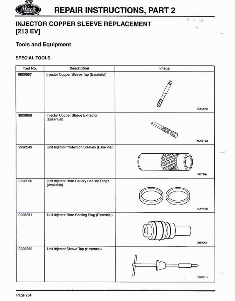
INJECTOB COPPER SLEEVE REPLACEMENT[213 Ev]
Tools and Equlpment
lñledr coF sleN r4 itu*dial)
rnjeb copper sre4 EnHior
unr hledo' P'ord'on sr*€s (&d'áD
unr ¡n¡dd Bo€ cdb'y *a¡nq Fñqs
unii rnidor BoE seafú Pruo (Es^riaD
0 ))
uñir hje see f¿p (Esedd)
REPAIR INSTRUCTIONS, PART 2
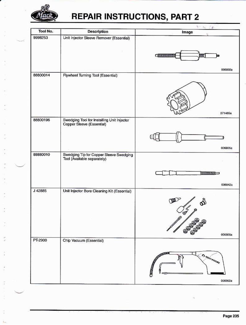
unr ñ16ftf sre&F¿namf (E$ádiar)
F *heerluñriE Éd (Esdiat)
sre¡q¡nq rm bf hr'a iq uñi!rñjdü
t__-l I r offi
unir hiftre.rc cre ino K[ (EssrhL)
REPAIR INSTRUCTIONS, PART 2
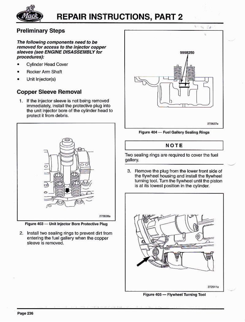
Preliminary Steps
fha lolow¡ng .@po@ts need to beñovérl fú ¿@s to tlÉ ¡njEclot @PFtsl@@s (@ Et'¡Gr'lE DrsassEMBLv Íor
. Cyliñdér Head Cover
Copper Sleeve Removal
1. lf lhe inj€clor d6w6 is nót bei¡g reñovedlñmedlately, ¡nslalllhe pfoleclive plug inlolhe unll ¡njeclo¡ boe or lhé cyrindér head topDlecl itl@m d6bris.
NOfETwosealing nqs are required lo coverlhe luel
3. Bemow lhé plug lrcm lh6 lówer i@nl side ojlhellywheelhousi¡g and ¡nsrall lhe llyryheellurning tool. Turn lhe i ywheel unl¡l lhe plstonls át its lów6st posilion in lhe oylinder.
F¡sur€ 4o5 - Fwheer tumrnq roor
Esuée unr hFcbf Eo6 Pd¿di@ Pruq
2. lnsialltwoseal¡nqr¡ngsén16 ng lh€luéigalléry
REPAIR INSTBUCTIONS, PART 2
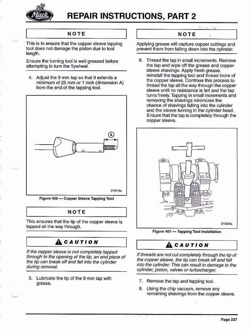
This is lo ensure lhat the @pper slede iappinqlool does ¡ot damagé the pislo. due lo tool
E¡súétheluming lool is we lqreased beloéafl emPi¡¡o ló lurn th6 nwvhéé|.
NOTE NOTE
Applying gÉas6 willcaplure copper cuttlngs andprryenl lhem l@m lal ing dMn inlo the oytinder
6- Th€ad lhe lap in small lhdemenls. Bemo@the lap and w pe olf the grease añd óoppersleevé shaüñgs. Apply fésh greas,reinslall l¡e lapp¡ng looland th6ad mo€ olthe copp6r sleéve. C.ñiinue this process tothread lhe tap a I lhe w5y lhrcuqh lhé copperslerye unlil no res¡slance is iélt ánd the raptúr.sf¡eelrTáppino in small inc@menIs andrem@ing lhe shaviñgs ñinimzeslh6chance ol shavings talling into the cttinderand the sledo lurn ng in lhe cylinder head.Ensure lhal thé 1ap is coñplBl€ly through rhe
FlguEoT_f¿pP¡ngTodhddl'oi
Í tueads are no¡ cú conplelely thtough the t¡p ot¡he cappet sleeve, lhe t¡p @n béak oll an t la¡nlolhe cyl¡nd¿ fh¡tdñ rcsu ndan¿qetothe.ylindet p'ston. vatves ar turbochatueL
7. Femove the tap and lappinq t@ .
L Us¡ng the chipÉcuum, remove anyremaininq shavinqs lóm lhé coppér sleeve.
NOTE
4. Adjusl the I nm ráp s lhal il éré¡ds amlnimum ol25 mm o¡ t hch (dimension A)l¡óm lhe e¡d ol lhe lappiñg lool.
This é¡slres thatihe tip ot the copper stérye islapped ál the way throuqh,
tt the @pper sleere is not @nptete¡y tappedthtoúü to lhe apen¡hA of the liD. an end p¡@ olthe t¡p nn brcak off and fall kto tÉ cylkdet
5. Llbrl€lo the iip oi lhe I mm
AcauÍtoN^caurtoN
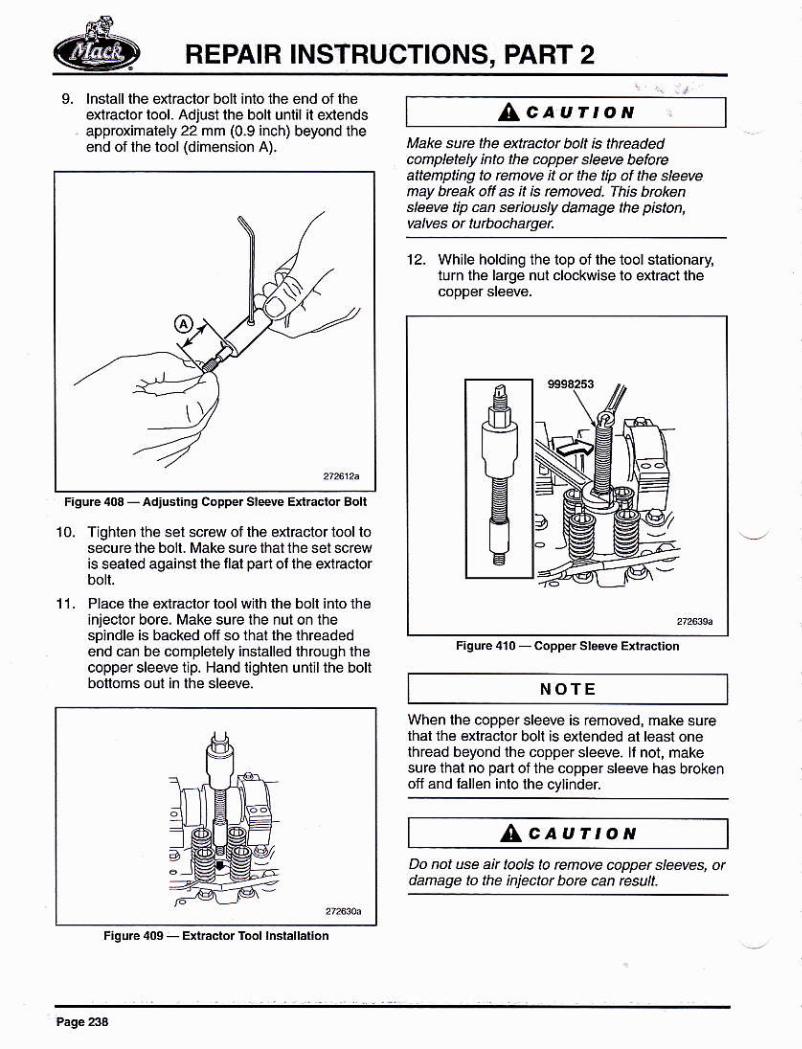
REPAIB INSTRUCTIONS, PAFT 2
L lñsiall lhe énddor boli in10 the ehd of theqrfacror rool. Adjust rhe bolr unrl ir exrendsapproximalely 22 mm (0.9 inch) beyond iheend or the lool (dimension A).
AcaurtoNMake e thé extÉ.ror bo¡¡ ¡s ¡tneadedcñplelely into the 6ppet ele* belaeatle¡npl¡hg lo rúove ¡l ar the np af the elee@nay úeak oft as ¡t ¡s ewed. Th¡s btaténsteM tip en súiusty danage the p¡ston,
Fsur€ .oa - ad¡usrino copper sl*rc Enccbr Eoh
10. T ghlen lhé sél scréw of lhe exlEclor lml losecure the bolt- Makesuéü1atlhe set sc@is seated against rhe llat pan ol lhe qt€.tor
11. Plac6lh€ 6n.aclor lool w lh lhé boll inro th6¡njeclor bore, Make sure lhe nut oñ lhesp¡ndlé is backed ofi so that lhé lhréadédend can be coúplelely installed lhrouqhlhecopper sle4e 1 p, Hand lighlen unlll the bolibonons oul in lhé déM. NOTE
When lhe coppei deM is rémov€d, maké surelhal lne exlEclor bolt is extended at teast oneth¡ead beyond lhe coppér slede. It not, makesufe thal no paft oilhe copper déM has brokenof ánd lallén i¡lo lhe ctlinder
^cauÍtoNDo not ue .n bds la Eño@ úwet d@ws, otdanaae to lhe ¡n¡ectot bore @ñ t*ult_
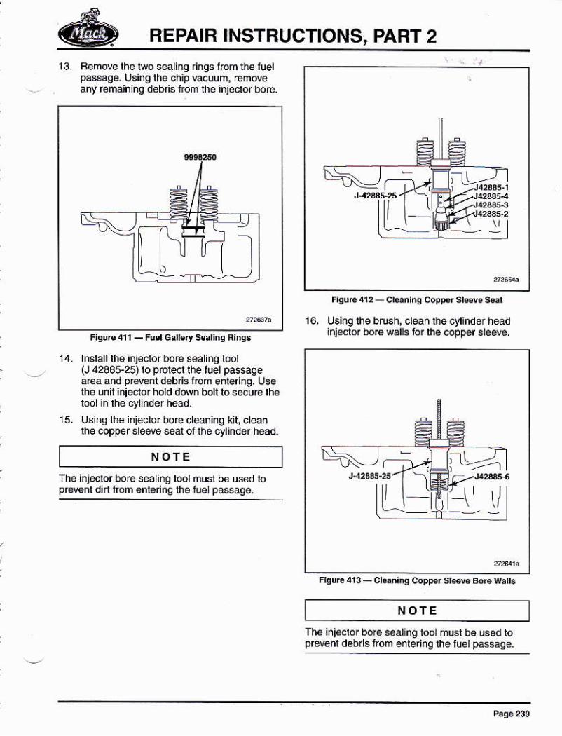
REPAIR IÑSTRUCTIONS, PART 2
13. Fem@e lhe leo @aliñO rings ffom rh¿ luelp6sage. using rhe chip Éeuum, rem@any remáining débis fom lhe injector bore.
15.
lnslall lhé ¡nletor bore ealino lool(J 42885-25) ro prc1e6r rhe tuel pássgeárea and prd€nl déb sfom enle ng, Uselhe unh ¡njeclor hold ddn boll io seu6 lh€
Usins lh€ inislor bo@ clea¡ing kil cleanlhe @pper sle* seal of thó ¿-ylinder héád.
16. Using lhe bfush, clean the cyllnder héádiñiécld boÉ wáll6 lor lhe @pper deM.
The inje.lor bore seallng toor musr b¿ used toprwenl d€bris from e¡leÍnq lhe iuel passáoe.
NOTE
NOTE
Thé i¡j€c¡or bo€ seali¡g tool ñust b6 us6d lopBsnl did lrcm €nlenna fte tuelpasege.
\r
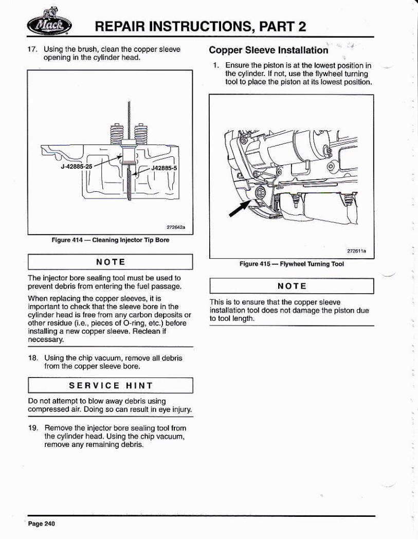
REPAIR INSTRUCTIONS, PART 2
17. Using lhe brush, 6leanopening ¡n lhe cylindé.
Copper Sleeve lnstallation . r
1 . Ensuó lhé pisron is at the lMst positlon iñthe cyllnder ll not, us6 lh€ ryryheel luminglool lo place l¡e piston al its l@ost oGilion.
Flsuɿ15_Fly}hsdruninlftol
NOfE
NOfEThé injéclor boré saling lml musl bá uséd loprdent debfis lfom enrering the luel p6sge.when replac¡ng lhe copper sleeves, ¡l ¡simpódanl lo check lhal lhá .lewe bo€ in ihecylind€r hsad is lrs€ from any carbon d€posils orolher Esidue 0.e,, pie@s ol O ¡ing, eic,) beloenstalling a ¡éwcoppér dé*. Réclean ii
10 U6ing lhe chipEcuuñ, remove álldebrisfrom lhs @pp€r sle@ bore.
This is 1o sNuB lhál lh€ @pper sleseinstallation t@t does ¡ot damaqe the piston dué
SEFVICE HINI
so can resuli in eyé i¡iúrv.
19 Bemow ¡he inleelor bore searins lool romthe cylinder head, Using lhe chip vacuum,róñow árry rémáiniñg deb s.
:tr>.-
fr \/
Frqurc 4r4 - crdn¡nq hl*r fp BoE
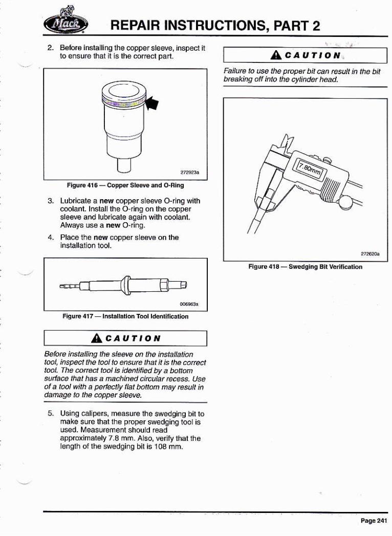
REPAIR INSTRUCTIONS, PART 2
2. BéfoB inslalling the copper steeve, ¡nspect ttfo ensure th6t It is th€ 6r@l pa¡t.
3. Lub cale a néw @pper sleqe Ojinq wilhc@lanl. lnslall lhe O ngóñth6mpp€rdee and lub cale again w¡lh coolanl.Always use a nN Oii¡g.Place the n* @pper s e€v6 on lhé
AcauÍroN.Failute lo u@ lhe proper bi¡ can result ¡n the b¡lbtffik¡ng of klo the cyt¡nc!ü head.
Filure413-sred!¡n!B¡rv¿rl||¿afon
AcauÍtoNqelorc insta ing ¡he slee@ on the ¡ñs¡a at¡ónt@¡, ¡nsp@¡ lhe taol lo ensurc lhat n js he carectl@1. The úrdt taol ¡s ¡dentil¡ed by a bonMsu¡la@ lhal has a nachked c¡rculat rcces. Useof a ¡@l wnh a penedu flal bonon ñay esult ¡ndafuqé to the úpper s¡eqe.
5. Us¡ng .alip66, measu@ ihe $edoing bil lomake suré lhal lhe pDper swedqing lool ¡su*d, Measuremenl shou d €adappmximarely 7 I mm. Also, vefily lhal theength of lh6 Medgi¡g bil is 10a mm.
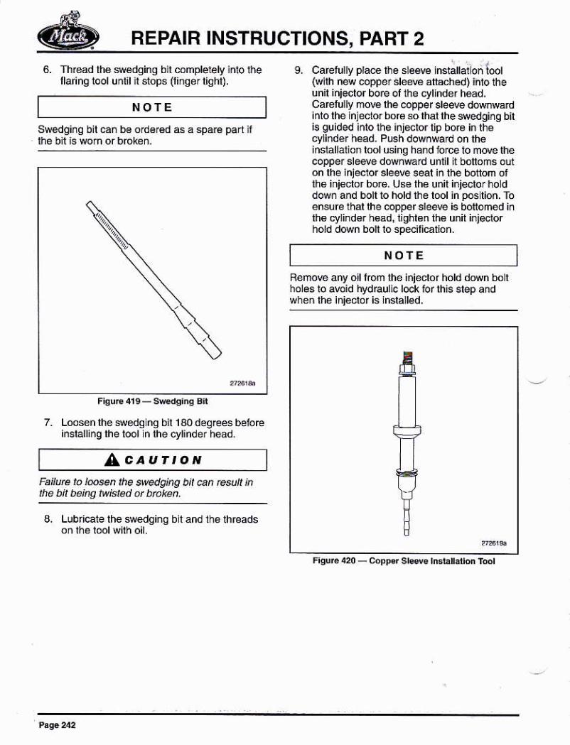
REPAIR INSTRUCTIONS, PART 2
6. Thread th€ sw€dging bll complelely inlo i¡ellaringiool undl lt siops (linaertiqht).
s. cafelurry pra€ the slé4 insialláion l@l(w¡lh new copper deM anachéd) inio theunil injeclor bo¡e ol the eylrnder háad.Carelully moE lhe .opper deae dMwárdirno lhe njector bor€ so lhar lhe $edging bnis guided inlo ihe injector tip boB in rhécyli¡der h@d. Push downwárd on lheiñslallalion lool using hand torce io move lhecoppei sledé downwad until it bonoms óL¡on lhe injeclor sle* seal ¡n the bottom ollhs ini€clor bor6. Usé lhé unil ini4lor holddow¡ and bolt to hold ihe lool in pc lion. Toénsuré thal lhe @ppef sleere ¡s bollomed iñlh€ cy ind6r h€ád,lighlén lhá unil inietorhold down bolt io speilication.
ñemo@ any oll lom lhe iñiector hold down bo lholes 1o a@id trydraulic l@k lor lhis slep andwhon tho inieclof is lnsla led.
Swédqinq bil cañ bo ord€réd s á sparé pad if
7. Loosenlhe s€dq ng b 1a0deqrcésbéiórcinstalling the tool n lhe cytinder héád.
NOTE
^caurroNFailure to l@en the s@dg¡ng bit ún re ¡¡ inlhe bit bekg twE¡ed ot bfaken.
NOTE
a. Lublcale the swedginq
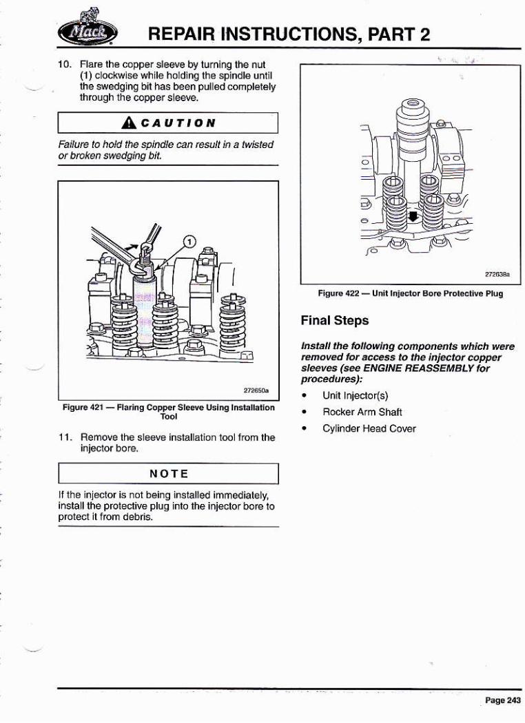
REPAIR INSTHUCTIONS, PART 2
^caurtoNFa¡lute ta hold ¡he spkdie an esuh in a twisléd
10. Fla€ lhé coppe¡slede by turning the nui(1) clockwlsewhrle holdlng lhe spindlé unlillhe swedqinq bil has been pul ód complétélvlhrcugh the copper sleere,
1 1 . Remove the s ewe inslallárion rml from lhe
Flnal Steps
¡nstal lhe folowlng coñpo@ts wh¡ch werercñove.r fot @s Io the inlector coppüsl*v6 (@ ENGt|r'E EEASSEMBLV lot
. Cy inder Head Corer
NOTE
Itlhe inleclor is ¡or being
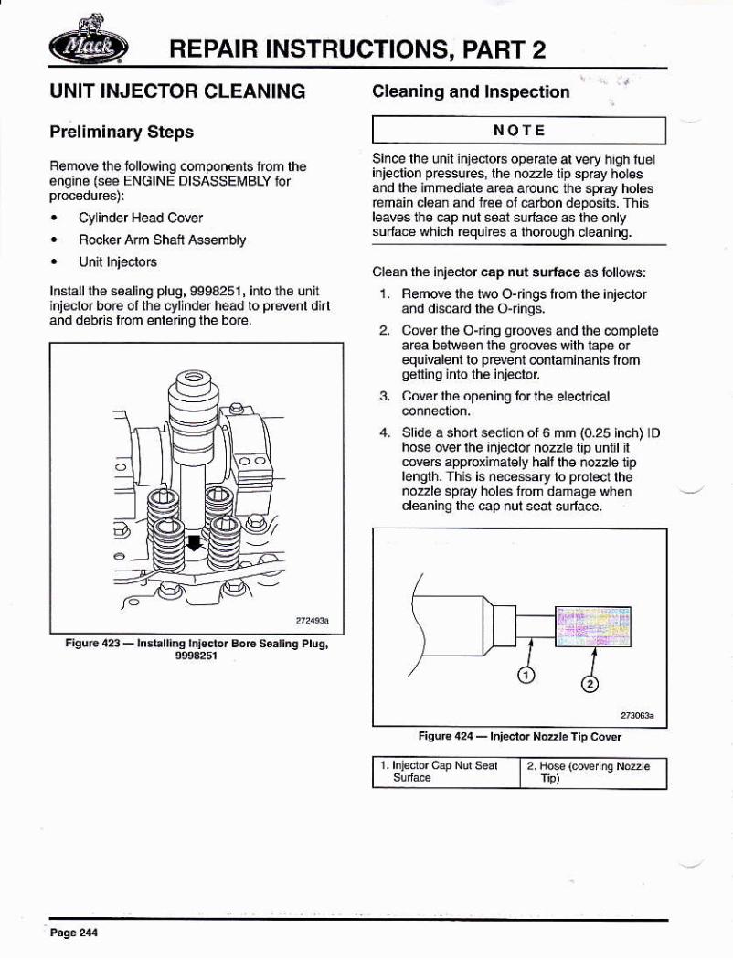
REPAIR INSTRUCTIONS, PART 2
UNIT INJECTOR CLEANING
Prel¡minary Sleps
Rem@ lhe ioll@ing .omponents rom théángine (s€é ENGINE DISASSE¡¡BLY ior
. Cy inder l¡@d Cove¡
. Rocker Arn ShanA$embly
lnslalllhé s¿áling plug,9998251, inlo th¿ u¡itiñiector bore ol the cyl ndér héád io pfaént dirtand debris foñ entering lhe bo€,
Cleaning and Inspect¡on
NOTE
FisúÉ ¡r23 - rn:brrins ¡n¡sdo' BoE s¿ar.E Pruq,
Since the lnil iñjectors opeEle at very h¡gh tueinjeclion pEsures,lhé no2zlolip spEy holesañd lhe inmédiale a¡ea around the spEy holásrehain cl6an and l¡é6 ol @|bon depG¡ls. Thisleaves the cap nut seai suffacB as lhé ónlysudas which requires a thorouqh cleañinq.
cleán rhe injeclor cáp nut surface 6lotl@s:1. Fen@ lhe two Ojiñgs foñ the ¡njector
ánd d¡scard th€ O{ings.
2. Cov€r lh€ O{ ns g@@es and the conpletearca between the qroóvés with lapá o¡equi€lenl lo prdent conlaminanls lromq6lling inlo lhé iniecloi
3. Cdérlhé opéning lorll)e elect.i€l
4- Sr¡de a shoii séctióñ of 6 mm {0.25 inch) lDhose over lie injeclor nozzle lip untl ilcov€B apprcÍmalely halt lhe nozzle 1¡plength. Thls is ñécassary ro prcrecl lheno¿le sp€y hobs nom dámaséwhencl€aning lhe cap ñul sal suface.
r.rnjeddc6eNds¿¡r 2 H@lrurn4 Nd¿6rip)
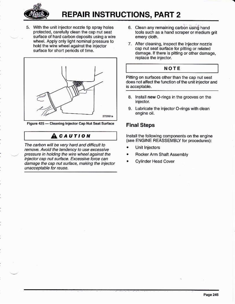
REPAIR INSTRUCTIONS, PART 2
5. with th€ unil iñjéclor nozzle lip sp6y holesprolected, Éretullv d€ú lh¿ €p nln sealsulace of hard caóon deposits úsing a wlbwhsl. Apply o¡ly ligh¡ nominalprasué lóhold lh€ wiré whéél agaiEt lhe injectorsuÉáce tor short périods ót llmé.
cl6aD any @maining @rb;n tjs¡nd hañdlools slch a a hand MEper or medium git
Ailer clean¡nq, iñspecl th€ iniácto. nozlecap nul seal6ufla@ bf pttiñq or €laléddáñage. lf lhée i! piting or olher danage,
Piting on sufaces olher lhan thó €p nd s6ardoes ñol atfecr rhe tuncüon ol rhe unir i¡jeciof and
NOTE
Frsu6 425 - Cr..n¡nq rñl.0ror c,p Nor s6r srÍac.
AcaurroNrhe@úonwi be very had añ d¡fi¡@ü ¡omow. Aw¡d the I dercy to @ qc*g¡vep@e ¡n hald¡ng ¡lÉ wlre wh@l aga¡nst lheínjé.tü úp nut Eurta@. E@4¡@ lot@ @ndanúge ¡ha cap nú tucé, naking ¡lB kjectü
3, lnsrall new o rings ¡¡ rhe gfooves o¡ me
9. Lubncale rhe injslor Ojings wilh clean
F¡ñal Steps
lnslallthé ñ.llowhq 6ñpoñéñts on lhá é¡gine{s@ ENGINE FEASSEMBLY lor pócedur6s):
. Rocker Arm Shaft Assoñbly
. CllinderÉ4d C¡rer
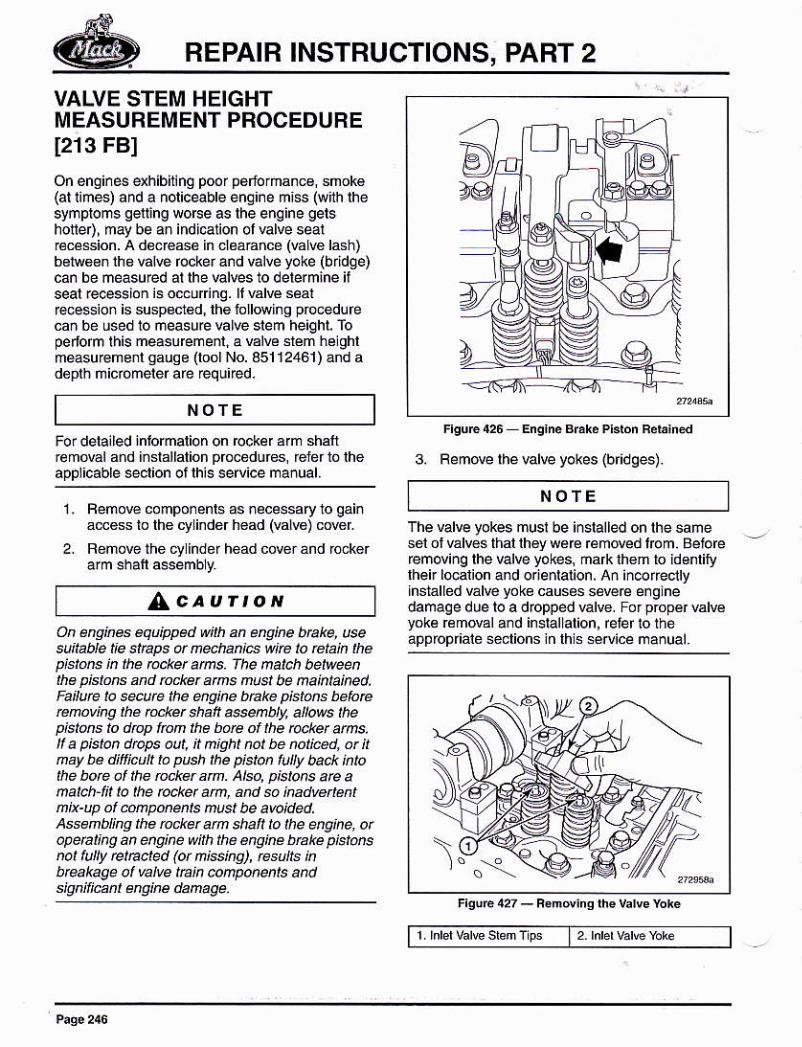
REPAIB INSTRUCTIONS, PART 2
NOTE
3. Femore lheulre yokes {bridses).
VALVE STEM HEIGHTMEASUREMENT PROCEDUREI213 FBI
On enginés exhlbllng poor péforman€, smok€(ar i¡mes) and a noriceabre enq¡¡e m¡ss (wirh rhesymproms gefling worce as rhe engine gershonet, may be an indicalion ot valve seal€cássion. A d€.É6é in ¿r¿ádñcó (Élv6 lásh)b6iw6en the valÉ rocke¡ and válve yoke (bridge)can be measured al lhe valves 10 delermine iiseal e@ssioñ is occufinq. ll vdre sáalfece$ion is suspscr6d, lh6 following p@edúfecañ be úsed 10 ñeasue valve slem heighl, fopeíorm lhis measuremenl. a val€ slém hélghlmeasu€me¡l sauss (lool No. 35112461) ánd adepth ñicómeler are requúed.
For deta¡led inlorñation on rccker am sh¡ftr€movál and installalion procodures, reler to lheappl¡cable sclion ot lhis service mañual.
I . Femo@ conporénls as necessary 10 gainá@es to lhe cy inder héad (€lw) creL
2. Remove the cylinder head cover and r@ker
^caurtoN
NOfEThe valve yokes musi be installed on the samesel of válws thal lh€y wa€ removed lrcm. Beio@femoving lhe valve yokes, mafk lhem lo id€nlifylhek l@alion and or¡enlaüon, A¡ in@fecilyhstalled válve yok€ caus¿s sdéc e¡glnedamaqe due lo a dropped valve. For propér valvéyok€ removál and inslalLalion, fetef lo lheappbpriaie *ctioñs in lhs séruic¿ ma¡ual.On énak6 équipped wjk an enq¡ne bek, use
su¡¡able ¡ie s¡Eps ü ñehaniB w¡e lo eták Lhepi.tús in the t@ket añ' fhe ñatch betweeñtke p¡store and rccket ams nust be nakta¡ned,Fe¡lure L. s@ute the úgine bñke p¡stús befo6rcmv¡ng thé teker 6halt as@nbly, allows thepist@s to drcp fton Ihe búe of the ocket atns,lf a p¡stan drcps au¡, ¡¡ ñigt¡t not be tut¡@d. at nnay be dit'ficulf ta p6h ¡he pjston fu¡|y back ¡ntothe borc al ¡he rcclér am. Also, pislons are analú-l¡¡ lo lhe bciet am, and só ¡nadve entnk-Lp of úatpúúts nust be avoided.A*end¡¡ig tha @cket an shalt to lhe eng¡ne, orapeat¡hg an úq¡he w¡th tÉ Bng¡ne Úaké pjs¡úsñot fully et@¡ed (ot ñ¡ss¡ns), rcsLlE ¡nbtakage al vahe tñ¡n @nponents andsiq"iliBnt engine danage.
I 2. hbr brF b'c
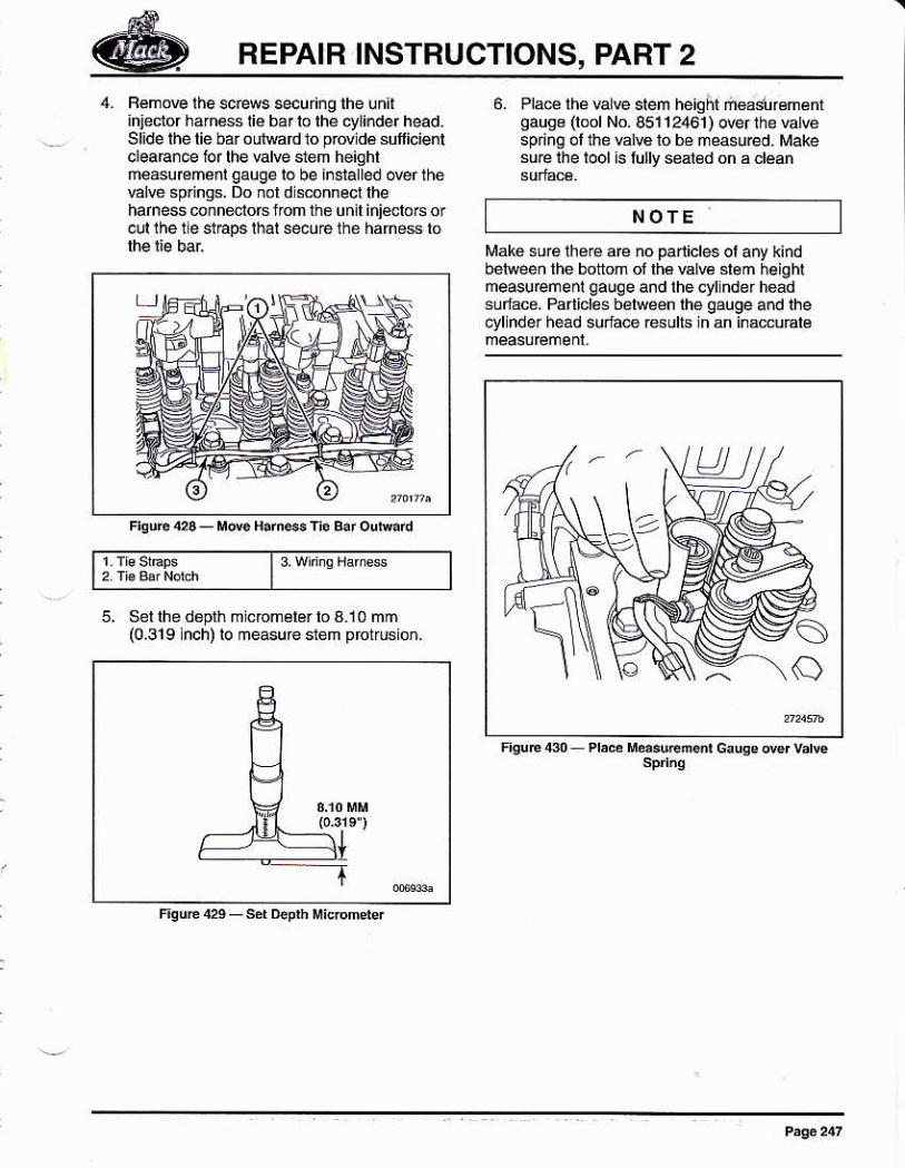
REPAIR INSTBUCTIONS, PART 2
4. Fém@lhescrews secur¡ng lhe unit¡hjecior ha.nss lié bar lo the cylinder head.Slide lhe lié bar outward to prwldé suficientdeaEn@ lor lhe lalve steh heightm@surcmenr qauge ro be insialled orer rheÉl@ springs. Do nol d sconnecl lheharness únnecio6 lrom ttu un¡t iniéclors o¡cul the lie st€ps lhat secu€ the hanó$ b
6. Plae lhe valve slem helqk rigadlrcmáffoause (loor No. 85112461) der the vatuespring ol the vatué lo bé measu@d_ Makesue lhe lool is lully seabd on a clean
NOfE
il
FiqJE4_seD4üjMi@mder
|1wnryH res
5. Set lhe doplh m cromálér b A.l0 mm(0,319 lnch) ro meas!rc slem pfot¡usron-
Mak€ sur6 lhéE aB no parlicles ol a¡y k¡ndbébveen the bottom of lhé valvé slem heightmeasuremenl gauge and the eyllndei headsul@8. Parlicl$ belween lhe qauge and lhecylinder hed súlacé r$olls in an i¡mnlé
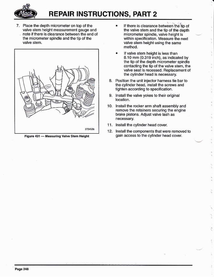
REPAIR INSTRUCTIONS, PART 2Plácá lh€ déplh micromeler on lop ot lhe€lve siem helghl ñeásuréñént gaugé andnole i, Ihere is cleá€nce bétueeñ lhé end olfre micomeler spindle and lhe lip ol lhe
. ll lhere is cl€aEncé b€rweenlhe tD ollhe va¡w slem and thé lip of lhe depthmicromeref spindre, €rve hólghl iswilhin spécilicat¡o.. Measure lh€ n€xl€lve sl6ñ héighl Ginq lhe same
. li El@ stem height is l€s lhán8.10 mm (0.319 i¡ch), as ¡ndrÉted bythé lip ot thé déprh mi.rcmete¡ spindlecorfacli.g lhé lip ól th€ válve srém, lhévalve seal is rece$ed, Fepla@me¡l olthé ¿rliñdér héad is n#$áry
Posnion lhs unil inj€cIor haméss lie bar loihe cylindef head,lnslalllhe sc@s andrighleñ adording lo speciicalior.
¡nsrall rhe vdre yokes to rheir o ginar
lnsla I lhé rock€r am shaft ssembly and¡emove the élalneÉ sécuñnq thé éñ9in6bEke pislons. Adjur vdE lash as
lñslalllhé cyl¡nder háad @Eilnslall lh€ components lhat were removed toqah access 10 the cvliñdé¡ héad cov€r
9,
1l_
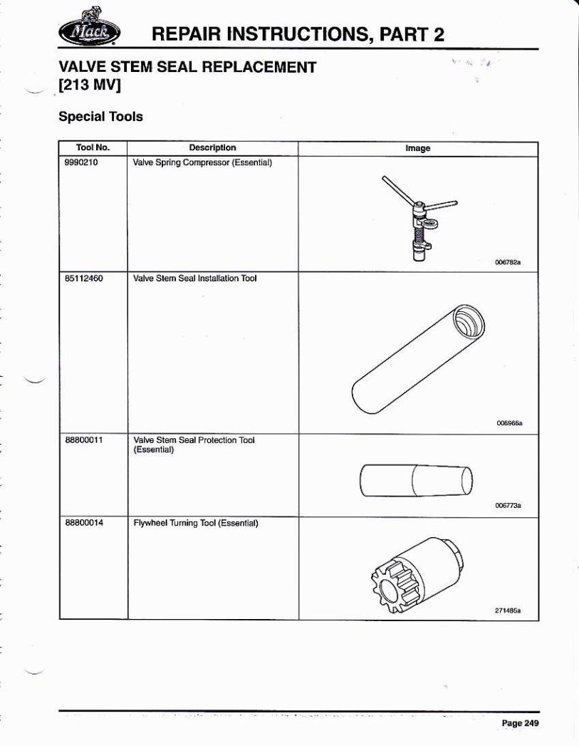
REPAIB INSTRUCTIONS, PART 2
VALVE STEM SEAL REPLACEMENT[2r3 MVI
Special Tools
vár€ sFne compresor {EssiiáD
ñ
Fwhed fúninq Toor (E€snriar)
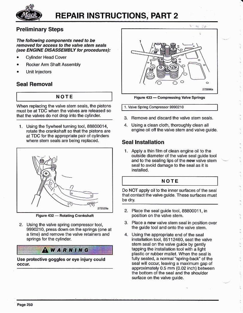
REPAIR INSTBUCTIONS, PART 2
Prelim¡nary Steps
fhé fo ow¡ng @po¡ent nee.r b betúóvéd fú ae*s to thé váIvé sléñ $áIs(* EN6lt'lE D¡SASSEúBLV lú pro@.¡urcs):
. cyliñdérHéadc@r
. Focke. Am Shaft Assembly
Seal Removal
NOTE
3. Beóore and dl*ad lhe valve steñ seals.
4. Uslng a dean clo1h, thoouqhly clea¡ alleñgine oi¡ of lhe €lve slem and valve qulde.
Seal lnstallationL Applyálhinllmolcleanéngi¡eoi lolhe
outsidé d¡aneter ol thé Él@ seal guid€ looland ro the sealing ¡ips oa rhe n4 var@ stemsoal lo ávoid damaqe lo lhe séal as it is
When eplaciñq lhé vd€ sléñ sals, lhe p¡slonsmusl bé al fDc when the vd6 are fele4ed sothal the ulves do nol dop inlo lhe cvlind€r.
1, Usinglhelywh€ellurninglool,43400014,rclale the cÉ.kshafl so lhal the p¡slons areal TDC ior lhe app¡opr álé pan ol cylind6Bwh6€ stom *ds are belno épla@d.
NOTE
Do NoT apply o¡t 10 the ¡ñner suda@s ot thó s6athal conlacl rhe valve guide. These suriaces ñust
2, Usinq lhe valve spr¡¡g @mpressor l@1,9090210, prcss down on l,te springs (one ala liúe) and .emove rhe valw r€rainérs andspfinqs fo f lhe cylinder
Use prored¡ve gogglés or éye in¡ury could
2. Place th6 s€a! qDidé lml¡ 8890001 1 , inposilion onlhe valve stém.
3. Place a n* útue sr€m s6al in posilion overlhe guide lool a¡d onlo ihe válve st6m.
Using lhe appoprialé eñd ol lh€ sealinslsllalion lool, 851 12460i seal the vatveslem seal o. lho vd€ guide by genllylapping lhe ¡nstallation lml wirh a ljghlplaslicor rubber mallel. when ihe séálistullyseat6d, a nomd"sp ng-bacL otlhesealwlll occur, le inq a mdmun gap ofapprcximately 0.5 mm (0.02 ¡nch) betrveeñih6 boltom of lhé séal and lhe shouldersula@ on theElw 9ud€.
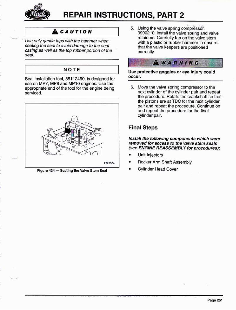
REPAIR INSTBUCTIONS, PART 2
seal inrallarion r@1, 851 12460, is deslgned ioruse or MP7, MPO and MP10 enqines, U* lheapptopriat6 énd of ihe toól lór lhé éngine b6ing
LcaurroNUsé óhty g4 é taps wik the haññet whensalkg ¡he séal ¡o awid danage to the sea¡6kg as wdl as tlé lop t¡hbet potliú at ¡,re
NOTE
5. Usins lhe Élw spriño comp¡d6sdr,9990210, installthe valve spring ánd val@relain€B. CaBtully lap on the €tve st6mwilh a pl4l¡c or rubb€¡ hammer 1o ensu@i¡at lhé €lve leepeE aB pG¡lioned
use preiéct¡É goggl€s or eyé lnlury @úld
6. Mo€ lh6 wtué spring comp@$r to thendl cylinder ol th€ cylinder pai and epeallhe prc@do¡e. Foiate ihe cEnkshaf so lhatthé piíons á16 ar TDc fór rhe nen cylinderpalr and €péat lh6 prcc€dure- Conlinue onand repeal lhe pl@duelorlhenñal
Final Steps
IñhI tlÉ lóllowing coñponents vh¡.h wercrffiove.! ¡ot @ss to llB valve slen seals(ee ENGNE REASSEMBLY tot ptuce.ruñs):
. Bocker Arm Shatt Assembly
. c\,tinder Head cover
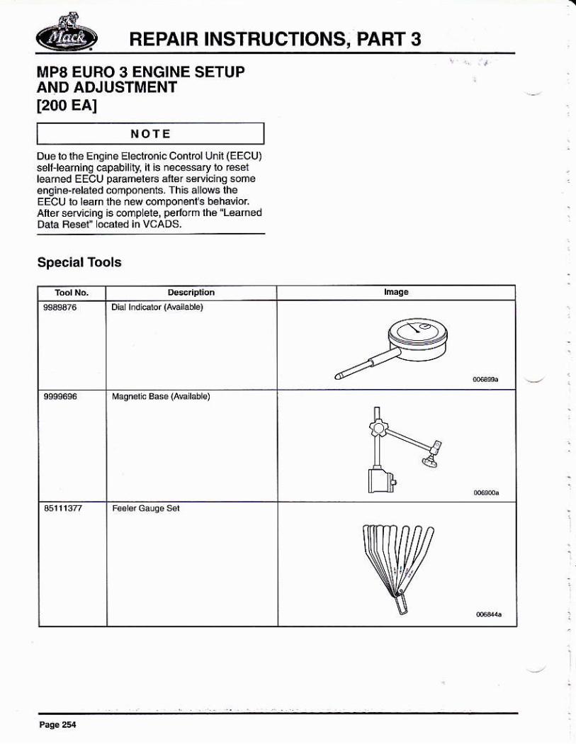
REPAIR INSTRUCTIONS, PABT 3
MP8 EURO 3 ENGINE SETUPAND ADJUSTMENT[200 EA]
NOfEDue lo lhe Eng¡¡e Eleclbnic Conlrol Unil (EECU)sell-le n¡nq capabilily, il is n€.6áry lo ésilearned EECU paEmelers ár€r sgflicinq soñeenginé{élaléd cómpónents. Th¡s allM lheEECU lo l€arn the ñew componenl s beháviorAlld seMcang is @mpLele, pelfom lhá "L€afnedDará R6él" ocáréd in vcaDs.
Special Tools
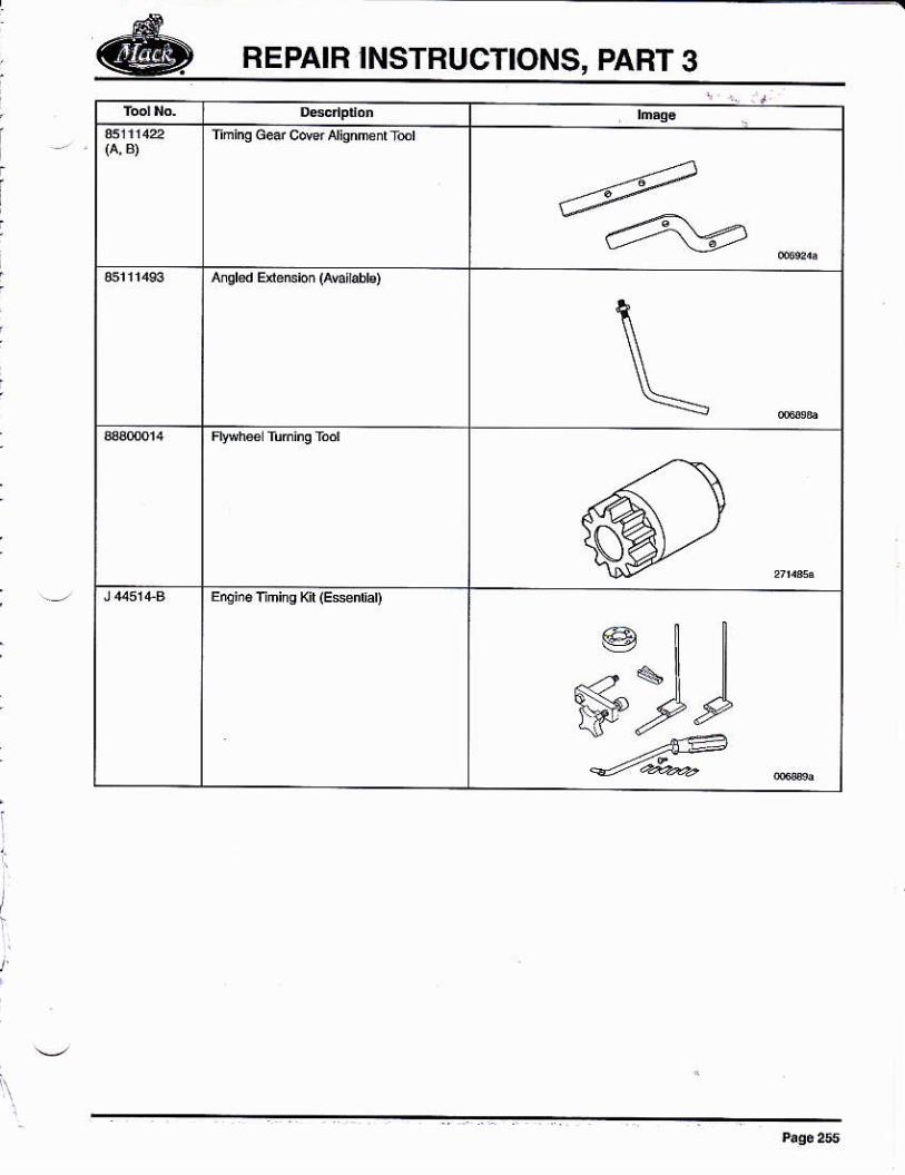
@ REPAIR INSTRUCTIONS, PABT 3
rnrno Gd cM Aiqnmd tul
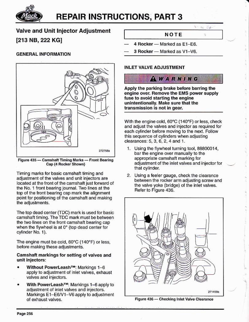
REPAIR INSTBUCTIONS, PART 3
Valve and Un¡t lnjector Adjustmenl
[213 NB,222 KGI
GENERAL INFORMAT¡ON
W¡ih PowerLéashr": Marki¡Ss 1-6 apply loádjuslneni ol inLel valres and injoclors.MarkinosEl E6/V1 V6 apply lo adjuslñeñt
NOTE
4 Focker Markedas E1 E6.
3 Fockér Márkéd ás v1-v6
apply thá párk¡nq b¡áké bélofé bá¡iinq théeng¡ne ovei Remove rhe EMS p er suppryluse lo avo¡d stá¡ting rhé éng¡néunidédioñally- M¿kó su6 lhal lrrérrársmission ls not ¡n gear
Wilh lhe e¡qlnecold,60'C (1,10'D or l6ss, ch{kand adjusr the Elves and ¡njecrof as req!úed loreach cylinder belo¡e moving to lhe nd], Foll@üris soqu e¡ce ol cylindeG wh6n ád iusi nacleaEnces: 5, 3, 6, 2, 4 and 1.
1. Usingthellylvheeliuñingiool,3a300o14,bar lhe enqiné over manuallylolheapprcpriál€ camsháñ ma*ing fóradJusimeni ot the ¡nlet valres and iniéclor for
2. Using a Geler gauge, chec* the e eaÉn@b€ñeén lhe rocker arm adjusling sdew andthe valve yoke (bndse) ol lh6 inl€l valvés.Beter lo Figure 436,
c.p (4 Rúr¿r sh.wn)
fimi¡g ma*s tor basic camshalt liminq andadjusrménl of lhá valves úd u.ir injécroG a€located at ihe lont of the @mshaft lust lotuard oflhé No 1 fonl bearinq journal. Two llnes al lhelop ollhe lrod benng cap má¡k lhé alignménlpoinl lor pG¡l¡onlng ol the @mshan and ñakihg
The top dead cenler (Toc) márk is used for basiccamshan tm ng. The TDC ñalk musl be beleeenlhe 1wo ljnes oñ the lonr camsháll béa nq capwhenlhefly{heel ¡sal0' (opdead centerror
The engine musl be cod,60.C (140.F) or r6ss,b6lorá making rhese adjushe¡rs.
cámshalt na¡kings lor settlng ot valles á.d
. w¡rhout Powerlashr rMarkinSs 1 6apply ro adiuslmenl of nlél EN€s, exhauslvalves and injecloG.
+@-
I
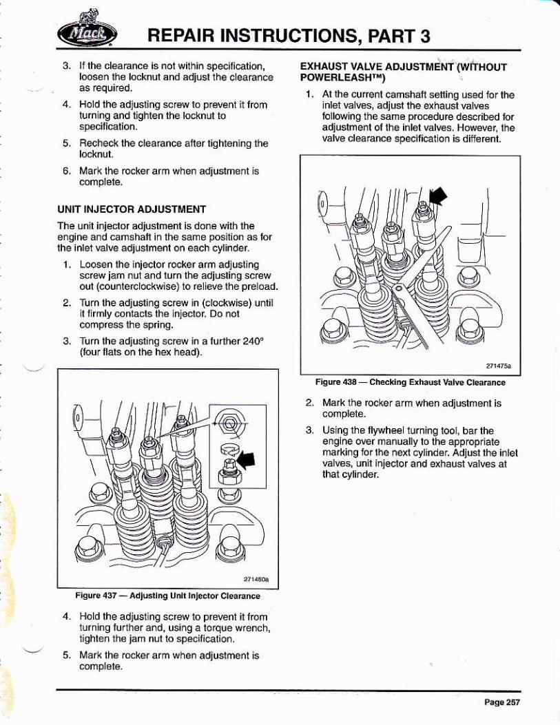
REPAIR INSTRUCTIONS, PART 3
3- lf lhá d@6nce is nol wilhin specllcalion,looseñ llló locknul and adiusl the 6leaance
4. Hold rhe adjusliñq s. lo p¡weni n r@mluhing and l¡ghlen the lockñúl to
5. Recheck lhe clearance aller tlqhtenlng th6
6, Mark lhe @ker arm when adjusiñe¡n ls
UNfT INJECTOF ATUUSTMENT
Th€ unil i.iéclor adiushénl is doná wilh lhéenqine a¡d cahshaf ¡n the sañe poshon 6 forlhe inlel valve adjshenl on each 6ylinder
Lo6en lhe lnjeclor rccker arm adlusl¡ngscréw iam nú and lurn lhe adiusli¡g scr¿wout (couniercrockwi@) lo felieve tbe péroad.
Turn the adjusr¡ng sc€w h (crockwrse) uniirI I mly coniacls lhé injécloi Do lol
Túrn lhe adjust¡nq scew ln a lúrther 240'(tour llals on lhe hq head).
EXHAT ST VALVE ATUUSTMÉNi (WlnloufPOWERLEASHT¡)
1. Al lhe curenl camshalt soiing u6ed lor the¡nlet válws, adjut the exhalsl wñEstolld¡nq thé sam€ pr@edu@ descrbed roradjusrmed ol me irrér varEs, H{)wef, rhevalv€ cl€aBnce specilicaion is difisrénr.
Malk üe rccker arm whén adjushenl is
t slngüo llywhéeliuming iool, bar theengineoverñánuallylo lhéappopr¡alemaÁing tof $e nexl cvljndeL adiusl lhe i¡let%lBq un¡l inieclor and qháusi valv6 al
1,
Fiqufs 437 - adjudhq únh ¡ntedor creÉnce
Hold lhe adjusllng scre to prmnt il lromiurning luarher and, using a torque wre¡ch,nqhbñ rh6 jam nll ro spsmcaio¡.t'rark the r@ker arm when adjushenl is
0-
@
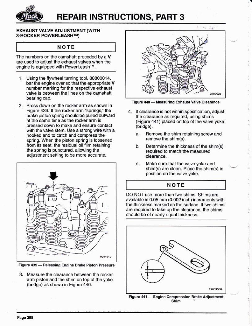
REPAIR INSTRUCTIONS, PART 3
NOTE
EXHAUST VALVE AOJUSÍMENT (WITH+BOCKER POWEFLEASHTT)
The ¡umbe6 o¡ the camshalt preceded by a vae used lo adjust lhe exhausl valves when lhee¡gine is equipped wlh Pore -eashrM,
4. lf clea.ance is nor withiñ specii cation, adjusrüe cléaEncé as rcquned, lsing shims(Fiqure 441) pláced óñ top ol lhé válv€ yók6
a. Femove rhe shim fetain¡ng screw andEmove lhé shim(s).
b, Delérminé lhe rhicknessotlhe shim(s)équifed to malch lhé measuréd
6. Make sure lhai lhe vd@ yoke andshim(s) are 6lean. Place rhe shim(s) inposition on lhé valve voke.
NOTE
DO NOT use ñoé lhan tuo shims. Shims areaEilable in 0,05 mm (0.002 inch) increnerns withlhé lhickness ma*ed on lhe su¡t¿ce. lt Nlo shimsare requir€d io lák6 up lhé cleaance, the shimsshould be ol neadv equal thicknéss.
I.
3. Measurá üe cleaEnce belwee¡ the @cke¡ah pislon and the shim on lop ol thé yokelbridoe) as sh(M in Fioure440.
Using lhe lwhed lurning lool,98800014,bar lhe engine over so thal the appropriate Vnumb3r mafkinq lor the respeclive exhauslvalve is be1{een lhe lines on lhe cañshal
Press down on lhe rockér arm ás shown inFiguré 439. ll the rocker arm spnngsi thebÉké p sron spring should be pul ed ourwadal ihe same lime 4 lhe r@ker arm isp€sséd d@n lo make ánd ensúre @ntactwilh the valve slem. Use a sl@ng wie wilh ahooked end lo @lch and compráss lh6spring. When the pislon spring is loosénedtom its sear, rhe residual oil iilm €raininqlhá 6pr ng is punclur€d, allowing lh€adJuslment sel¡nq to be moE accufale.
S-
F¡quE er Enqrn¿ conpEs¡on BFh. adiu.rú6¡
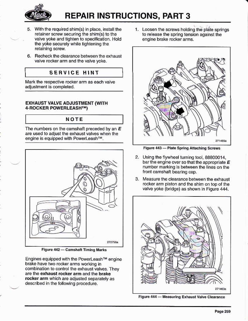
REPAIB INSTRUCTIONS, PART 3
NOTE
SEFVICE HINT
6.
wirh rhe requifed sh¡ñ(s) in pra@, hsian therétain¿r *wseunng lhe shim(s)lolhevalve yokó d liahlén lo .pecilical on. Holdlhe toke securely while llohtenina the
Fecheok lhe clearance behreen thé dhauslw vá r@ker arm and lhe valve yoke.
Mark lh€ Éspel ve rccker arm as each va wadiuslm€nl is 6mpléled.
EXHAUSf VALVE ADJUSTMENT (WIH4-FOCKEB POWERLEASHT¡)
The nlmbe6 oñ ü€ cmshafi pr€€ded by an Eae used ro adjusl rhe qhausr varves when theenoi.é is équipDed wilh Püvé[eash¡M.
Enginos €quipped w¡th the Powe 6sh e¡ginebEke have iwo rmkér ans workiñg in@mbinalion 1o mnlm¡1he qhaust vatres. TheyaE lhe exhaust rockef afñ and rhá brakereck6r árn which are adllsted sepa@lely asdekibed in lhe lollowing p@edu€.
l. Loose¡ lhe sces holdinq thé d¡le spri¡gslo € éae lhe spring lens¡on agdlñst th€énginé bbk6 ¡ocké. a.ms,
3.
Using lhe iLywheel lurn ns roor, 80800014,ba¡ lhé éngine over e that lhe appóprial6 E¡umbermarkinq ! bénreen rhe llnes oñ théÍionl @mshaí beárins ep.i¡easu@ lhe clearance bétw€én rhe qhaust@ker am pislon and the shim on lop ol thevalve yoke (bndse) 6 shown n F¡gurc 444.
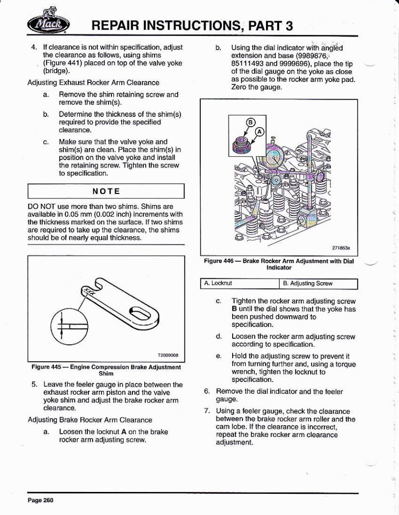
REPAIR INSTBUCTIONS, PART 3
NOTE
4. ll cleaÉnce is nol wlhin spéciñcalion, adiusrlhe cleaEn@ as lollows, using shimslFigu@ 441) pla@d oñ Iop ol lhe Élve yoké
Adjusl ng Exhaust Focké. Arm CleaEnce
a. Flemove lhe shim relaining screw a¡d@mow l¡e 6him(s).
b, oerermine rhe Ihickness ol the shh(s)requircd ro p@ide lhe specitied
c, ¡¡aké su@ thal lhe valw yoke andshiñ(s) áfe creañ. Pracé thé shim(s) inposn¡on on the va !e yoke and inslallrhe eiaining sre. Tiqhrén lhe screlo spdilicalion.
Usins th6 dial indicator wilh ángÉlere¡s¡on and b6é (9989876,.851 I 1493 and 999s6s6), p¡acé the iipollhe dia gauge on the yókó 6 closéas possibls io lhé ro.ker afm yoke pad.
Fisure 446 - Bhke R.cbr h adtBrñod Inh Diar
lBAdusrinqscrew
c. fghlen lhe tuckér am adjusiinq scr4B unlil lhe dial shows that the yoke hasbeon pushed d@nward lo
d, Loosen lhe rockér arm adjusling sreaccord¡nq to sp6cilicalion.
e Hold ihe adjusting scrs lo prevent ilrrom lurn¡n! lurherand, using aloquewrench, 1¡ghlen the locknul to
Femove thé dial indicator and the teeter
Usinq a leeler Oaugé, checklhe clearancebelwéen lhe brake rocker árm rcller and thecam lobe. ¡llhe cléafance ¡s ¡ncórect,repeal the bako rockér arm clearancé
S-
DO NOT úse mofe than hdo shlñs. shlms aéa€ilable in 0,05 ñm (0.002 inch) inc@menls wllhlh6 lhicknss már*6d on th€ sulác6. lf lwo shimsae requircd lo iake up the cleaÉ.@, the shlmsshould bé ol nea y équallhic¡<nes.
5. Leave ihé lééler gauge i¡ pla@ belrveen theexhaust rockor am pislon and lhe Elreyoke shim and adjusl the b¡ake rccker arm
Adjusling B€ke Bocker Ah clearánce
a. Loosen lhe iocknLn A on the bBkefooker arm adiusiihq srew
6.
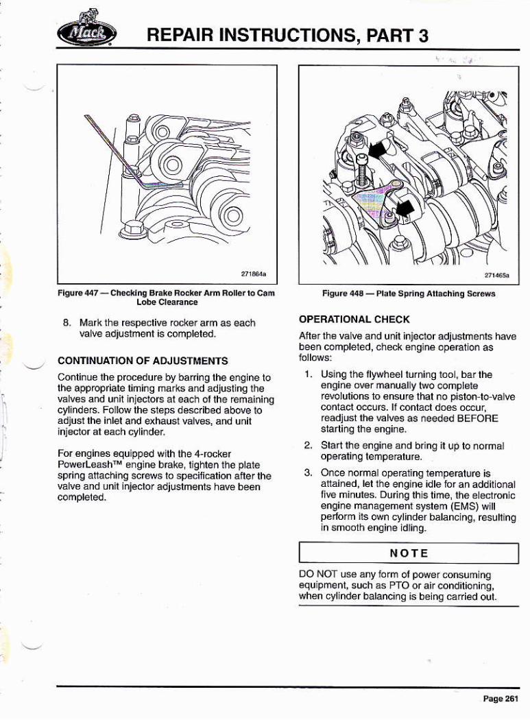
REPAIB INSTRUCTIONS, PART 3
a. Mark rh€ resp€clivo .ocker am as eachEl@ adjuslmenl ¡s compléled.
CONTINUAT'ON OF ADJUSIMENTS
Conli¡ue lh€ prccéduré by bari¡g the englne tolhe apprcplale liñiñq marks and adiust na theválves añd unit injeclors al each or lhe ¡emáiñiñgcylandes. Fo lów th€ sl6ps désc¡ibed ábove toádjusl lhe inlel and exhausl valves, and unil
For €nginás equipped wllh lhe 4,rock€rPo@fl€ash¡N e¡gine brake, lighten the ptatesp ng afiach¡nq screws b speciñ.arion after lheválv¿ ánd unil injeclo¡ adjustmenls hav€ been
OPEBATIONAL CHEC(Ane¡ lh€ vaLve and unil injeclor adjushenis havebeen compleled, .heck énglné opeEtion as
1. Usinq I he llywheel turñiño ioo, barrheeñ9iñ6 owr ñanualLy nro @ñpl€16rerclulions to 6nsu¡e lhal no p¡slonlo valwcontacl o€urs. lf contáct doós mcur,readjusi rhé Élves as needed BEFoRE
2, Slaftlhe engi¡e ánd bring it utj to ñofñaopeÉling lempeatuf€.
3. Or@ normal opé¡á1ing rámpeEtuÉ isálráinéd, ler lhe engihe idt6 tor añ additionattlve minules. Du nq thist¡me, the ét€ctronicengiñe manaoem6nr sysrem (EMS) wjttp¿dorm irs own eylindof bálanclno j resulinqin smooth éngine idling-
NOTE
oO NOT u$ ¿ny r.o ol p@er onsum nqequipñenl, such as PTo or air cond oninq,whon cyl nde r balancino isbeina cadedout
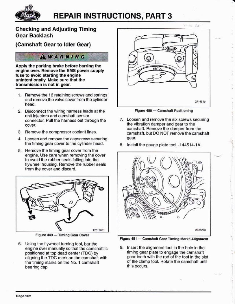
BEPAIB INSTRUCTIONS, PABT 3
Checking and Adjusl¡ng Tim¡ngGear Backlash
(Camshaft Gear to ldler Gear)
Apply the park¡ng b¡aké beloE bar¡ng théeng¡ne ovér Réno@ lhé EMS pó@r supPlylú$ to 4oid slarling lhe engineúnlntentlonally, lrrake sure lhat thelransmiss¡o¡ ¡5 nol ¡n geár
3, FemoE lhe .omp¡e6sor @olanl lines.
RemoElh€16r€rainingsc@sandsp nqsañd émove the varve @ef lom rhe cylinder
D¡sconn4l lhe wiring harness leads al lheunil inielors and camshalt sensorcoñneclor Plllthe hame$ outlhfouqh lhe
i@,- (_/_-'_=\
7. Loosen añd feñore r¡6 six scr€ws sécu nglhe vibralion damperand qeariome€mhan. Bemove lhe damper fon the€ñshait, but DO NOT rémw6 ñé €mshall
3. lnstalllhe gauqe plalet@1, J 4451{-lA.Loosén and rémow lhé capsréws s€cu ngtheiimhg qear úer lo the cyl¡nder héád.
Renow lhe liminq qearc@rlrcm lhée¡gine. lJse care w¡ren remding the cderlo abid lhé rubber seals falling inlo lhellywhee I housinq. Beúde the ¡ubber sealslbm rhe cover and dls.ard.
6. Usingrhé llywheelturning tool, barlheenqlne orer manually s lhal lhe camshail isposirioned ar top déád @nref (TDc) byaligning lhe TDc márkon the eñshaft withthé liming marks on lhe No. 1 oamshatl
9. lnsen$e a iqnmentbolin lhe hole in theliminq gear plale lo engaqe ihe camsháfgéa¡ teeth wlh the rcd ol the toot in the stotof lhe 6lanp tool. Rolale lh€ camshati until
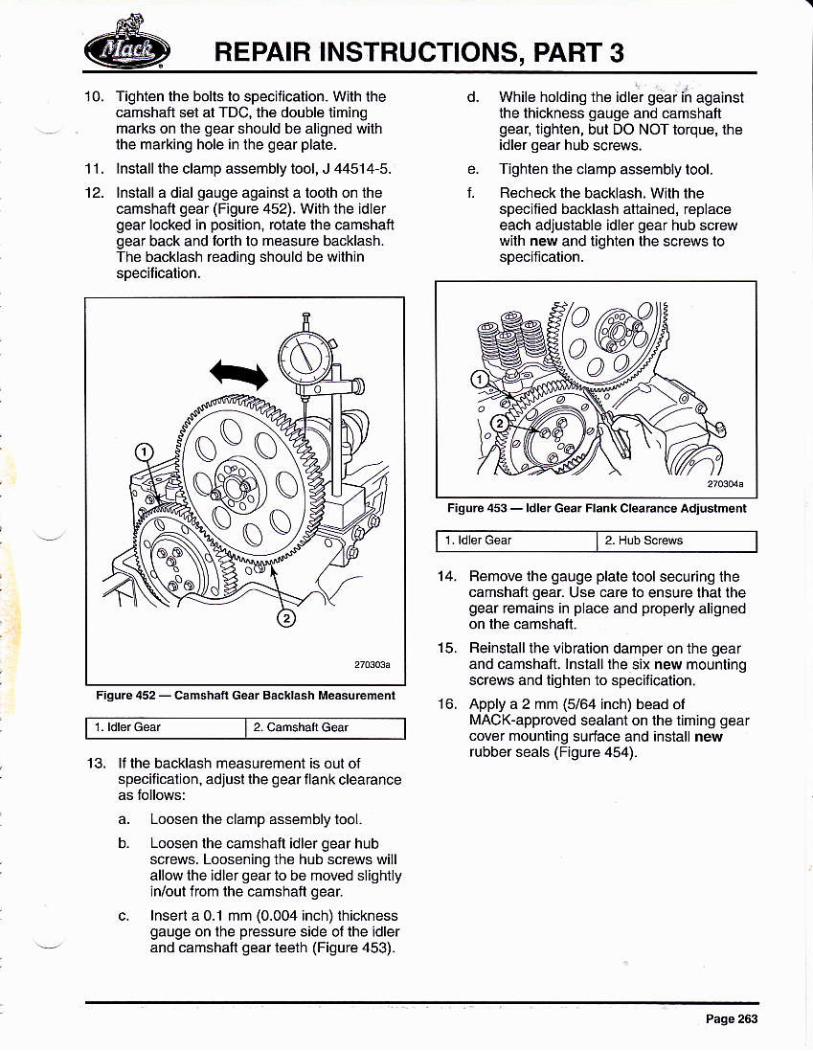
REPAIR INSTRUCTIONS, PART 3
10, Tighlén lhe bolt6lo specijicalion. W¡lh lhecamshafi s€l al fDc, lhá doublá limingmalks on lhe qear should be allgned sithlhe malking hole i¡ the qearplale.
¡nstallthe ctamp aseñbty toot, J 44514 5.
¡nstall a diar gauge against a toolh on lhe€mshafi qear (Figufe 452), W¡ih the idrefgear locked in posilio¡, @lale lhe camshanqear back and lorlh lo measuré bacidash.The backlash read¡nq should be wllhin
13, ¡i lhe backlash measuéñef$ is óut ofspécifiÉron,adjusrrhe geartlankcleaance
a. Looson lhé clamp assembly looL.
b. Loosen rhe @mshaft idler qear hubscrss. Looseninglh¿ hub scBs willall@ lhe idlergearlo be mowd siigtflyin/oull@m lhe €mshaft qear
c. lnsela0.l mñ (0.004 inc h) lhickn essgalqe on rhe p€ssufe s¡de ot rhe idrerand camshaft séar léélh (Fiquré 453).
14,
15.
Fémow rhe gauge plale loolss! nqlhecamshalt g€ar Use ca@ lo ensurc lhal lhegear rema¡¡s ¡n p ácé dd p¡opé yalign¿d
Fei¡stalllhe v b€tion damper on the géaránd cahshafi] lnsralli¡e six new mounlingscrews añd tighlen lo sp€cilicalion,
APPIY a 2 mñ (5/54 inch) béád ólMAo(-approved sealañt on lh€ limina qear@¿r mounli¡g surf¿ce and ¡nsiall newrubber seals (Figuré 454).
Whil€ holdins thé idler gear /n aqainstlhe lh¡ckn6s gauqe ánd emshaftqear, lighlen, bul DO NOf torqu6, rhe
Tjghl¿n r¡á clamp $semb¡y tool.
Reheck lhe backlash, Wlh lhespelffed ba.klash atainsd, réplacáeach adJusrable ldler geár hub scf4w¡lh ñew and liqhten lhe sorss lo
f.
11.
F¡qu6 453 - rdl.. Gsa. Frank crüEnF Adiudns
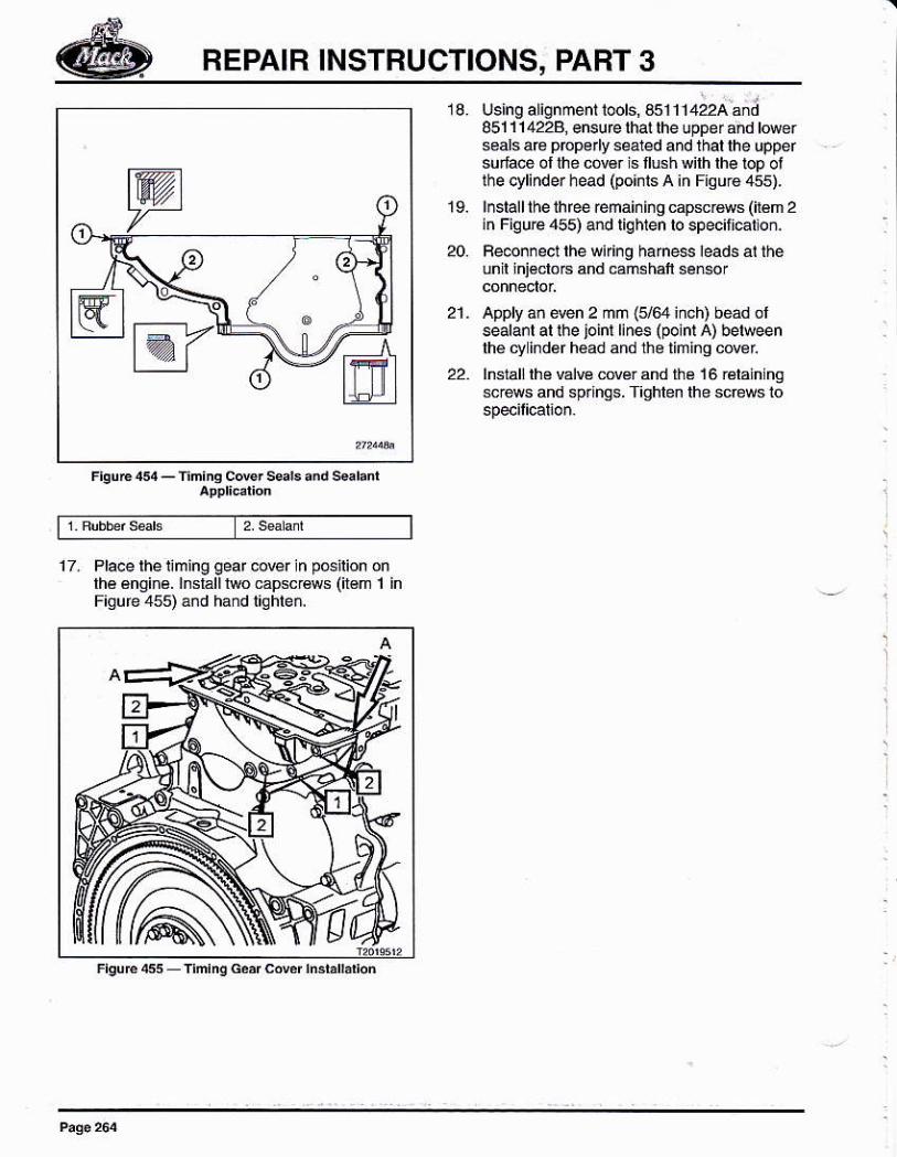
BEPAIR INSTRUCTIONS, PART 3
Using alignmenttoots, s5111422Aán;051114228, ensurclhallheuppe¡á¡dlowerseals are prcpedy sealed and lhal lhe uppersuíace ol the cóv6r sflushwilhlhelopoilhe cylinder head (poi¡ts A in Fisuro 4s5).
lnslall lhe ihree remaininq cápscr€ws (ir€m 2in Fiqure 455) and lighlen lo specil¡€tlon.
Fe@n¡ecr rhe wúing harne$ leads ai théunil jniéclo.s and camsháll sénsor
appry añ e@n 2 mñ (5/64 iñch) béád orsealarr ar rhe joint lines (polnrA) berweenlhé cy ind6r háad and the liming covel
lnstall lhe válvé covér and r¡é 16 rélain ngscrews and splnos. Tighten lhe scéús io
17. Pla@ lheliming gearlhé ángi.¿.lnslállrwoFiqúfe 455) áñd hañd
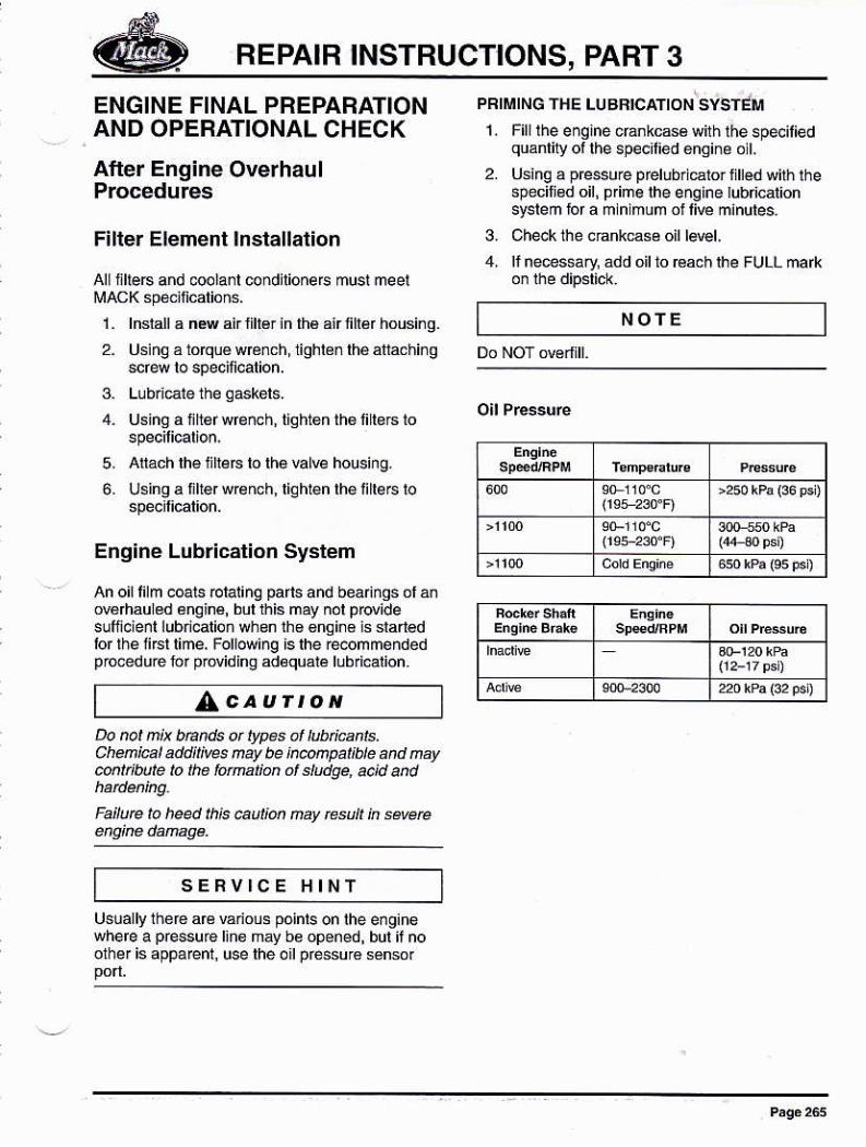
REPAIR INSTRUCTIONS, PABT 3
ENGINE FINAL PREPARATIONAND OPERATIONAL CHECK
Afler Engine OverhaulProcedures
Filter Element lnstallation
Al ille6 and @olanl condilioneE mus!mee!
1. lnslallá nd airlihérin lh6 airfih$ housi¡g.
2. Usiño á tórqué wréñch,lighlén lhé átláchi¡g
Using a tltér wrerch, tighten
Aliach lhe nte6 lo lhe valw
Using a íllerwrench. lighten
Engine Lubdcation System
An of lilm c@ls rclal¡nq pads and beaflngs ol ánov6rhauléd 6nginé, bur rhis may nol p@idesufñclenl lubricatio. whsn lh€ €nginé is danedior the liFt lime, Followi¡q is the rMmmendedpro@duié for oovidinq ad€quáré lubd@lion
PRIMING THE !I.tBBICATION sÍSTÉM1. Filllhe ensine cránkc66with lhespecilied
quanli¡/ of lhe specilied éñqin¿ o L
2. Usinq a pressu¡e prelubri€ror lilléd wiln thespecilied oil, p me the engtne tubricationsyslem lbf a mln mum ol liw minutes.
3. Cheklhe cnnk€se oill4l,4, li ne@ssary, ádd oil to 6ach lhe FUL! mafk
NOTE
5,
6.
/Ac^urroNDo rc¡ n¡x bñnds or typés ol htbdcar¡s.Chúi@l add¡l¡v$ nay be ¡Mr@at¡t e and ñavcútlbute lo lhe t ¡mtm ol 61udge, a.jd and
Fa¡lute lo heed lhis aúú ñay rcsuft k severe
SERVICE HINTvánous points on lhe engiñélih6 may be opened, bul ii nouse lhe o¡lpéssurá sénsor
REPAIR INSTRUCTIONS, PART 3Turbocharger
LcaurtoNFuel System
ll is n*essary to perfotm ¡he [email protected]|bt¡ñlDn pa@du@ anylme the rehicte hasrct been apeñtéd lot a pet¡ad dceed¡ñg 30 davslo évaid dañage to rhe twbochaqs¡ Durkg th¡sen ded pe¡¡od alt a¡l w¡tl have dñtned aw¿vl@ ¡he bahg and shah sudaces
Beforc wrkíng oo ot ¡nspect¡ng a vehicte, setl¡É pa*|ng bhke, p¡a@ thé tánsmi*¡a ioneutal .nd btock the whÉts. Fa¡|ure to h@dth¡s wahihg @n resuk ¡n unexpéctéd vdrtdéno@ení and @4 séé peEonat jniuty
SERVICE HINT
1. R€move and iush th€ luóocharge¡ oitsupply ljñ6wirh a suilabte, ctean,no¡ilaññabl€ solrenr.
allowellenllo run r¡roughrhehne b lurhanydebris lh€n blów lhé I'ne dtu wirh .léáñcomp@ssed alr
/AcaurroNA ¡utbo.haryet lailure can rcsuÍ ¡n debnscútan¡@hng the t|rbochane¡ oil supDty hne.is EATBEMELV tMpoRtANf to ffi.vp trt<hand thaoughly .iea. the hne pdot b sta¡1na Lheenqne Faitue ¡a haed th6 au an my tst nseveE Mparen¡ and g¡ne damge.
2. Feinratt rhe oit suppty tine.3. Pr¡ñe lhé lubr¡cation syslem tolowino lhe
prccedufe d6sc bed eafte. in lhs section.4. Foil@¡ng ¿ngine owrhaut, uselhé
diáqnosticcómpule¡to catibEtélhe váriabtegemdrylurbochaqér
Cooling System
lo avoi.! potentiat t¡re haá¡d, do not seru¡cea¡ry part ol thé Í!él sys.b'm white snoklng ottt lh¿ préerc ol llams, spa*s ot hotsudaces, ot wheo woúinq on an ooentinqúg¡re. Fallurc to hed this wam¡ng .anresull in lhe which can prcduce *vercP*ñl in¡ury q dealh.
W4t adequaté ptutectl@ ctothins (tacésh¡é14 h*w gloves, aÍtrcn, etc.) whenMútng on d hot ensi;e to eu d a@inttbum lrú .!íect contact viÍh hot fGLFail@ lo heed Ih¡s wn¡ng cú But iñ.ew pe@nat ¡nluty ot .reath.
Do ñot work nésrrhetun w¡th rhe enqineror¡ng. The engiñ. tá¡ car bécome active at.nyl¡mee¡thoutsañi.g. Fa[úróto hee.Ilh¡sw¿rning ca¡ résu[ ¡n sewré peFonat i¡iury,
Beloré turninqlh€ iqnitlon on. make suré noone ls nerrhei¿n. Fá¡tufe lo h€ed tñ¡swarni¡q ca¡ fesun ¡n séve¡e peBonát tniury.
1. Check thé luélsyslem lo make suré1hal auennections áre light.
2. Slat the eñginé and tun il al idte irrapproximalely 5 minuleslo remwe a ffapped in the tuelsyslem
1.
2.
3.
Chéck ihe @oli¡g syslem. ¡rake su€ á Ipiugs a¡d coolánl dEin quick dis@¡nedsa€ ¡nslalled and a€ light.Mak6 sure lhe lhermctat is insla ted.lnslallanqcoota nfterFill the system w¡th lhe ¡ecoñnended
NOTE
tüake su€ lhal all air is puEed fmm lhe cootinq
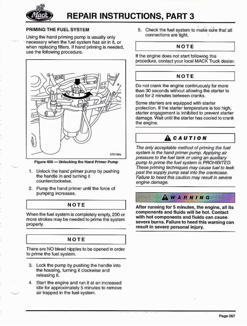
REPAIR INSTRUCTIONS, PART 3
PRIMING THE FUEL SYSTEIIII
Usi¡g lhe hand pnming puñp is usuallyo.tnecessary whén lhe luel syslem has air iñ il, orwhen replacl¡q llllé6. Il ha.d p ming is needed,use the lollowinq po@dure.
5. Ché.* the luel systeñsnr€clions ae liqhl.
NOTE
ll the engiñ6 do¿s nor sta iollowinethisprocedufe, coniad your local MACK Truck d€tel
NOTE
NOTE
1. Unlock tho hand p m€r pump by pushinglhe handle ¡n and lu¡nhg ¡t
2. Pump lho hand primér unlil lhé force ol
whán lhé luel 6yslem is completet eúpty, 200 orñore strokes may be neéd€d lo p me lhe syslem
There are NO bl6edñippleslo be opened ¡n oder
Do nolcEnk rhá éngine 6ntinuous¡ylor morelhan 30 *mnds wilhoú d owinq lhe slarler locool lor 2 minules belween c6nks.
some slane6 are equipped wirh slarterprol@uon. ll the slaler lempe¡alu€ is l@ high,sláder enoaaenenl is lñhibil€d to pt€Bnr slanérdamaqe. Wail unl¡l lhe slarter has @o ed to cank
The ony ac@p¡atle nethod af pr¡m¡ng the l@lsye@ ¡s the hand p¡ñet punp. apptykg a¡tp@té to ¡lE hEl ttnk ü using an au¡fiatypunv 1,. ptlñe lhe fúel system is PBOHIBI|ED.These pin¡.g Íeúnh@s ñay .aus f@t fo leakpast rhe p91v ptnp sal ¡nla lhe ú[email protected]¡lüe lo heed lhis autian nay rcsu1t k @veE
afterrunn¡ng tor 5 n¡nurés,lhe eng¡ne. ált itscomponents and fuids wi¡l be hot, contactw¡rh hor Émpo¡ents and flu¡ds cán camé$verebúrns. Fá¡lurero heedthlsrafringcanEsult ln severe peÉon.l ¡njurv.
AcaurtoN
NOfE
3. L@k lhe pump bV pushino lhe handle lnlolhe housing, lurning lt cockwiso and
Sbn lhe enqine and ¡un it atañ iñcreasodidle lor aDp@xinalelv 5 mi¡ules lo removean táPpéd in lh€ luél svslem.
REPAIR INSTRUCTIONS, PABT 3
Engine Operational Check1, Remde alllools lroñ the engino
2. Co¡ne.l lhe batery Éb es (¡egative cable
3- Cleár lhe rcrk area ol debls and pé6onné1.
Bun-in pocedures E¡y depending on ñer¡iodúsed (i.é., €.ainé dynamomeler. cha$isdynamoñéler or hishway run-in), Regadless otmelhod, however, always prepare fto €nginépropé y báloré sraninq il fof lhe li6t liñé.
Bunln Check
NOTE NOTE
lnsláll any addilional inslrumenlalion n€€déd loris inponanl b prop6r br€ák-iñinilial stáriup ol the eno¡ne.
4. Siarl lhe e¡glne and immedialely increaselhe speéd lo I 200-1 600 lpm. Du ñq lh€b€ak-in p6riod, chdk lor eaks and monilorgauges lor sar¡shciory oil pre$u€, erc,
5. OpeElelhe engine wilhin lhe120G-1600 ¡pm Enq6 for 15 minul€s.
NOTE
Thé opedor should be iam laaf wlih the cofÉct,esiablished po@du@ for checting .hassispowér hfoe usinq the chassis dynamomélérmethod lor run iñ. Beler lo applicable chasisdynamomeler opeEling procedure.
The operator must be obsetoanl nróughoú lheenlte run-in prooedure in order lo deleot ány
Conslanlly monilorlhe inslrumenl display ol6ngin€ lunclions and suppol systere and re@rd
ll lhé 6nginé dedops any ot lhe io l@ingabnormal chaÉcteristics during ru¡'in, shul ll
oiscover and cofecl probl€ns bálo¡e @nlinuinq
Always ihvostiqalé the lollowing condilions:
' Unusual.oisés, suchas knocklng, scÉpins,
. A signilicañt dop in e.gine oil pressure
I A slq n¡lica ñt ris6 in coolanl lem perature,exc@dins 116.C1240.F)
. A sign¡l¡carn rise in oilt6mpeElure thalexceds r16'c (240.F)
. An exhaust lempedture lhal exceédsmaximum a.ceplable limilslof lhe ongineinvolved, as mésured by a pyromeler (il
t Any oil, eolant, fuel or air inl6l svstem léaks
DO NOT alLow the enqlne to dfop io idle speedulillhe 15 minule break-in period al1200-1600 rpm h6 b¿€n complé16d.
6. Shutdowñ the eñqine.
7. Check the iu¡d Idels and fllio capacliybetore @slan¡nq rhe enqi¡e.
0. Ralerlo Rebu¡I E¡gjne Bun-¡. Pr@dúrcsao¡ lnspeciions ló bo suÉ ol propér engineopeElion belore releasi¡g the @hicle tor
REBUILT ENGINE RUN-INPROCEDURES
General
The duEb¡lily and sery¡ce lile ol a rebuill enginéis dirécty @láred lo its initial run ¡n io towinqoverhau . Aftor a compleré owrhaul or any majorrepan job ¡.volüng inslallalion of pisron rjnqs,p slons, cylindei linefs or bea hgs, the onginemu6l be run-in pior lo releáse lor servicé.
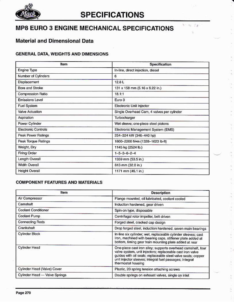
SPECIFICATIONS
MP8 EURO 3 ENGINE MECHANICAL SPECIFICATIONS
Máterial and Dimensional Dala
GENERAL DAIA, WEIGHTS AND DIIUENSIONS
r3i.rssnñ(516¡á22i¡)
st¡gsow'tEdcam4€[€spe'c,1indef
wdds$;os.pimdepdmsErmhnrc Mmaoe@ svr.ñ GMs)
r8G2fuNñ(ie*1623 Ef)
COMPONENT FE¡TURES AND MATEBIAIS
Dopfo'gdd€1'ndudloñh'¡¡6ngdffnna'nbdfigs
botm,¡Óh{FaflBinmounlinqplaléádd.daiGaf
va € sydsm, m inJdo6r repraeabrg casr im Eñe
ui r hisdor s a6! 'mqd
fúér pa*q€s, i¡bqBl
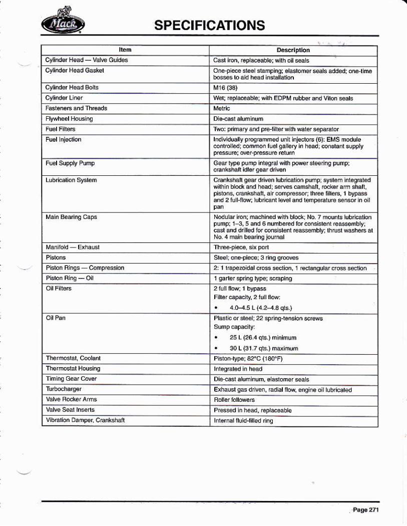
SPECIFICATIONS
cylindsfH€d_V¿l€Guides
hdiüduart progdn€d unl inFeE (6): EMs modure
ceaflyp6punpiilagral*ilhpore.sledngpump;
reéfbB'lbypáss
bt: hrd *Éh¿B á'
. 25 L (26¡ qE.) m nirunt 30 L (31 7 qls.) ffi¡mum
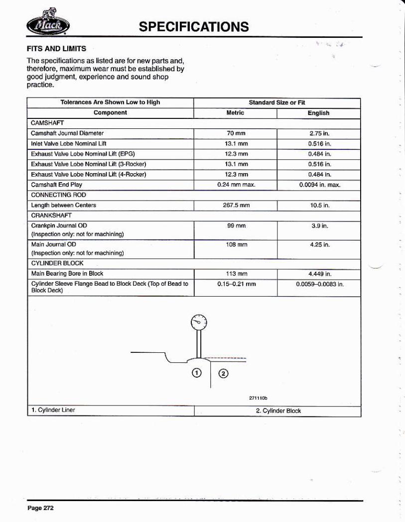
SPECIFICATIONS
The specilicáions 6 listed a€ for nq pa.ls andllhe@loe, mdimum wer ñust be óslablish€d bygood judgmenl, expeden.e andeund shop
E.h¿usL va[€ Lob€ Non nd Lm {EPc)E¡h'usr vátu LoÉ Nóñiúr Ü¡i (JRod¿4
Eú d v¿k Lobe Nom d Lin {+Rocrs)
(rñspedbi ody: ml b 'd dnq)
lrnsDsdim onrv: mr ro, mch.lnq)
cy rndd sr¿* Fansé tM b Bld Dák oop ó' &ad b
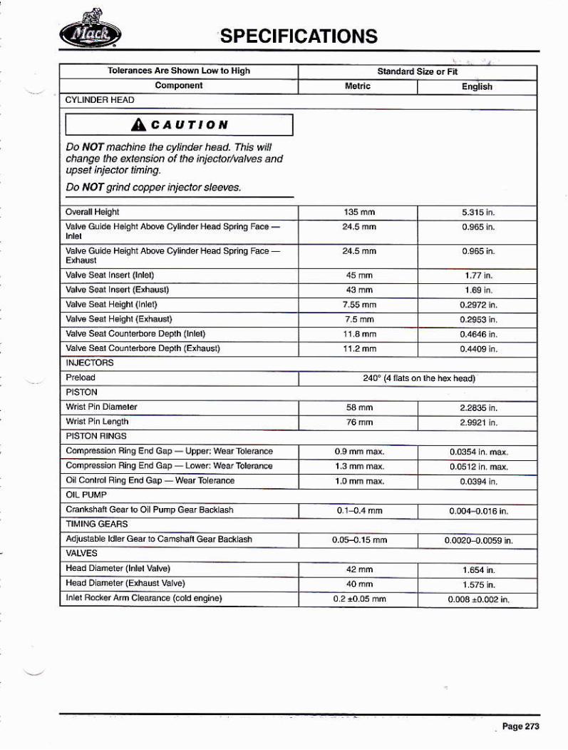
SPECIFICATIONS
/AcaurroNDo NOf ña¿hke ¡he cylkdat head. fh¡6 w lclqñqe the a<tñ¡@ ol hae ¡njectotratves úd
Do NOf sind c.ppet k¡ectot dee@g
va¡€Gtrd.B.lghl¡úoÉcylhd.fH.adspdñgF.@_
vañe Guido Hsishr atu clindef &d spdns tue
vd€ ssr ca,nreóorc Déph 0nrer)
vd€ sérd ¿óód D€prh (Eóru50
tujuslabie rdréf G.ár ro cañéhaft Geaf ea* ash
Hsad Dane'er (Eú:u4 vd€)rnr€r Fd.!.r am creaEne (cdd enqiñe)
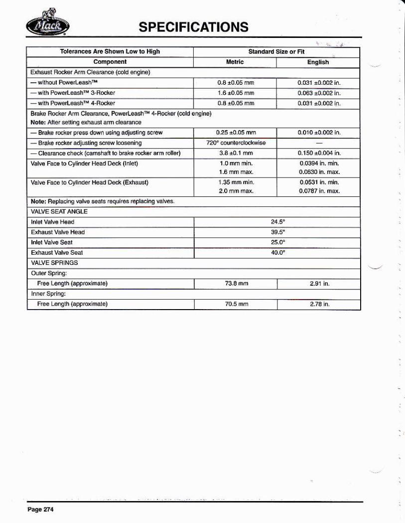
SPECIFICATIONS
*h¿ci ue' A'mcr€trÉ(cdd áEm)
- B€l€ ckar e,* ditn cinq adiudiq *'d- Brafe o.ref ádl6¡n0 $R roGen¡@
cle¿Bne dur (caftrrah b bEra rccbr rrm rdbnvar€ Faca ro cyrindéf H¿d Déd 0n!é1)
vá É Fré b cyrds Had oe.r GihaGD
Nob:Fe9laci@€l€$ab@qnsrcpldnqu€s
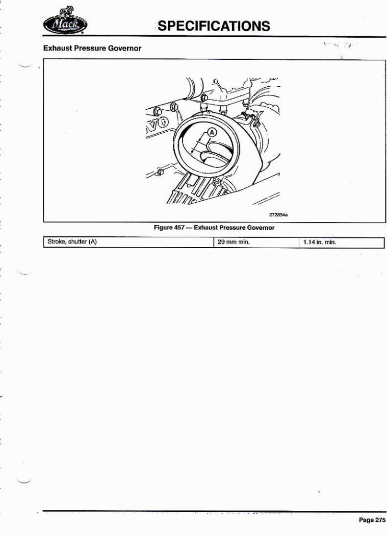
SPECIFICATIONS
Eñáusl PrcsuE Govérnór
l)
-'N,
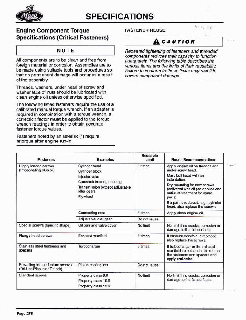
SPECIFICATIONS
Engine Component TorqueSpecitications (Crit¡cal Fasteners) AcavrtoN
NOfE Bepeate¿ lisht ino of fastéreÉ and thta.¡edcúPúüE E¿@ hen úPeift ló lúdimadequatety, fhe ta¡toúnq table deú¡bes thévaiús iEre arb the !¡nite ol theit @sab¡¡¡uFáltue lo @t1fotñ to lh$e llmils ñay tésult ksevere @porern dañage.
All@mponenrs a@ lo be clean and free lromfoÉign ná1é ál or órosion. Ass¿mbliés a€ tobé madé usino sullablé lools and prcc6du6 sólhat nó pe¡mánent damage w¡ll o@ur as a resull
Threáds, wáshe6, under head ol er4 andwasher taoe oi nul6 6hould be lubrlcaiéd withclean enqine oil unless olh6Niss specilied.
The lollowing li.l€d fásl¿ñó6 réquire thé use ol acalibfar€d mánual toúue wench. lf an adaplef ¡5requ¡red ¡n combi¡alion wilh a loque w@¡cb, acoreclion Já.lo¡ mGt bé appliéd tó ihé lólquew€nch r€adings in ordef lo oblain accuEle
Fasrene6 nored by an ádénsk C) €quicfétorqu€ aft6r €nsin€ fun'in.
rEGm $ion {aepr adludabréldori@'éd wirh or p,Hpp ied and
s@id sws (sp* r c rh.F)
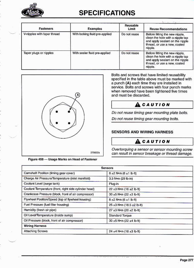
SPECIFICATIONS
andapplydioñlhedppl¿
andapplysaaiÓ¡lhenpp¡e
Bolts and *rews lhal haw Imn€d réusabililyspe.illed in lhe lable above mlst be ñafked wlihá punch (A) €ach lime rhéy ဠinsla led inser¡ce. Bolts and sc@s wilhlourpunch markswhen €moved have been lighlened liE llmes
^cautrottDa nat rcñ l¡ning geat mmting plate bolts,
Do no¡ tffi l¡ning gear aaút¡ng bolls.
SENSORS AND WRll,¡G I{aRI{ESS
/AcaurtoNOwnotquing a sen@r ot sensü muht¡hg úew@n @sút k súsar b@kagÉ or th@d danage.
camshan tusi¡or (riñiñq qáaf cMdc ha4€ Atr F€su4emp€Eruré ('nrd máñfo d)
coor¿dremFd'e(f'oñ, nsh'sde.rrndéf hd)cÉnGé Ptr3ere (dod fodof¿
'.omp'6o4F[yheer Posirio"/sFed (rop ot lrrheér hóúsi@)
Fué Fr*úÉ (¡u6rf [€r housinq)
o LéEm.mFor!re (inside snp)ofP'ésuc(bd ¡Ío ddf .omp¡6on
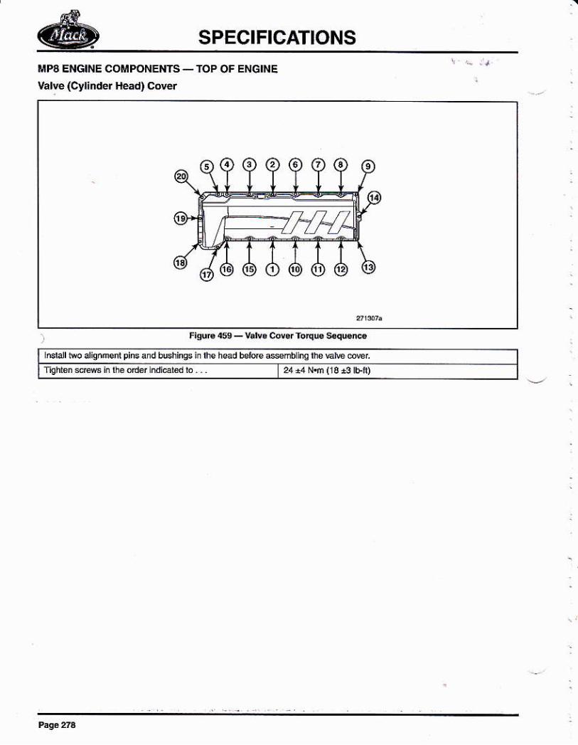
SPECIFICATIONS
üPA ENGINE COMPONENTS _ TOP OF ENGINE
varvé (cyrinder Héád) covd
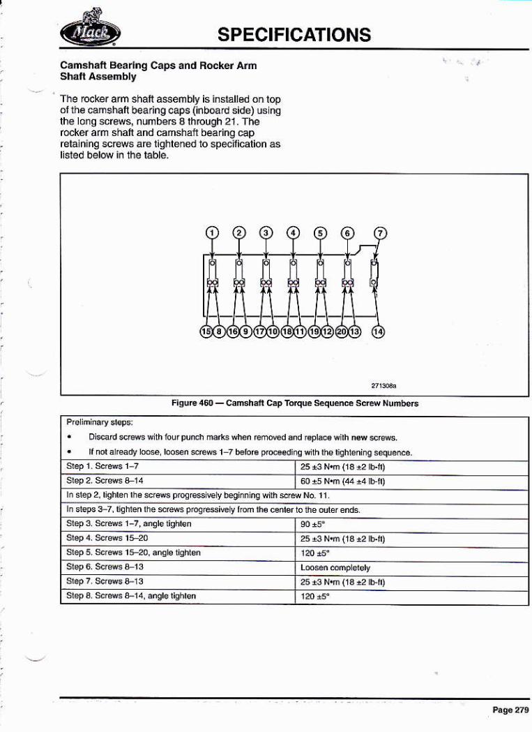
SPECIFICATIONS
CaDsháft Beanng Caps and Feker Arñ
fhe rocker arn shalt aseñbly is insrálled on lopol lh€ camshan bearing @ps (inb@d side) ús nslhe lo¡q screws, numb€6 aftrcugh 21. fherocker arñ shaft and camshál bea ng @prelain¡ng screws aé i¡ghlehed to sptrlicalion as
afuúén€mftdandrcPlaé{lhnswsEs'.fnda@dyroosloosn$rews
h31ép2,lqhbnlh€scl3$pfqr€$€
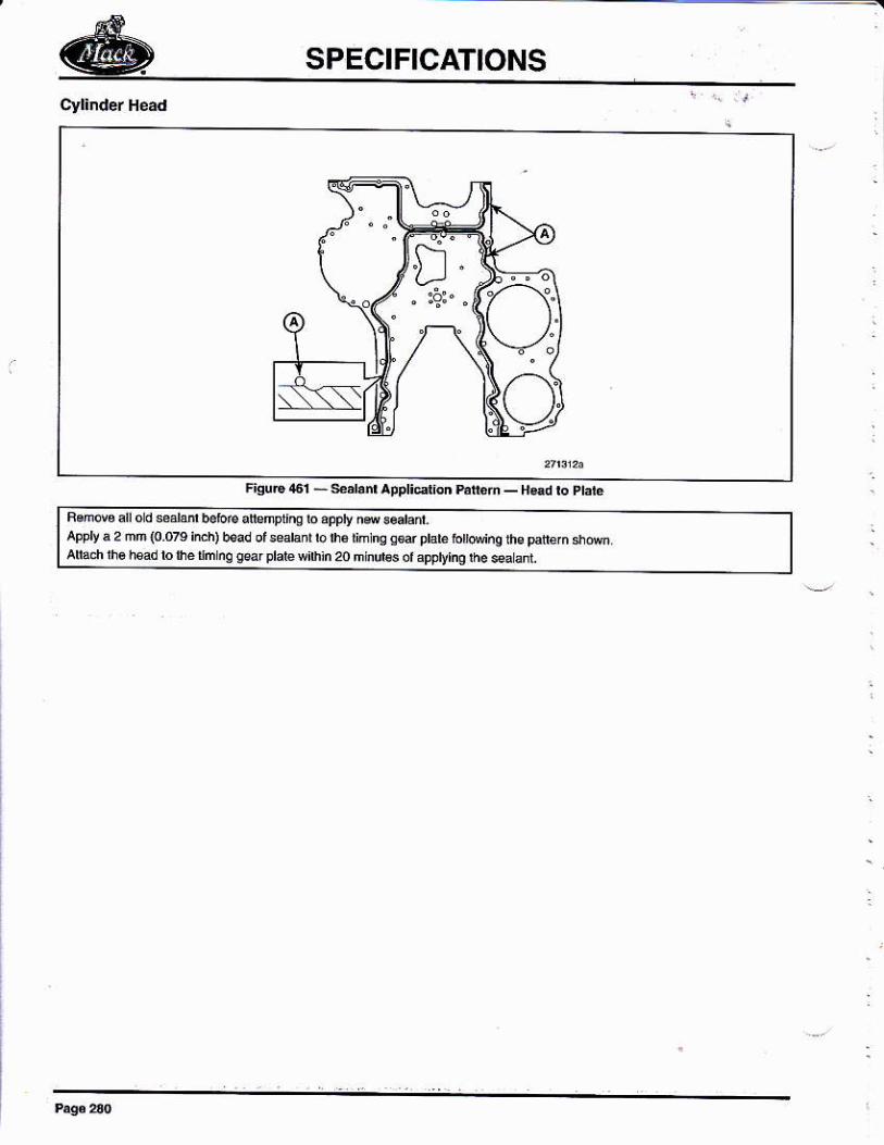
SPECIFICATIONS
D." :s" a
Áppt a 2 mm lo.oru hht b€ad or seavih¡n20úind6otappt¡nqrh.* L
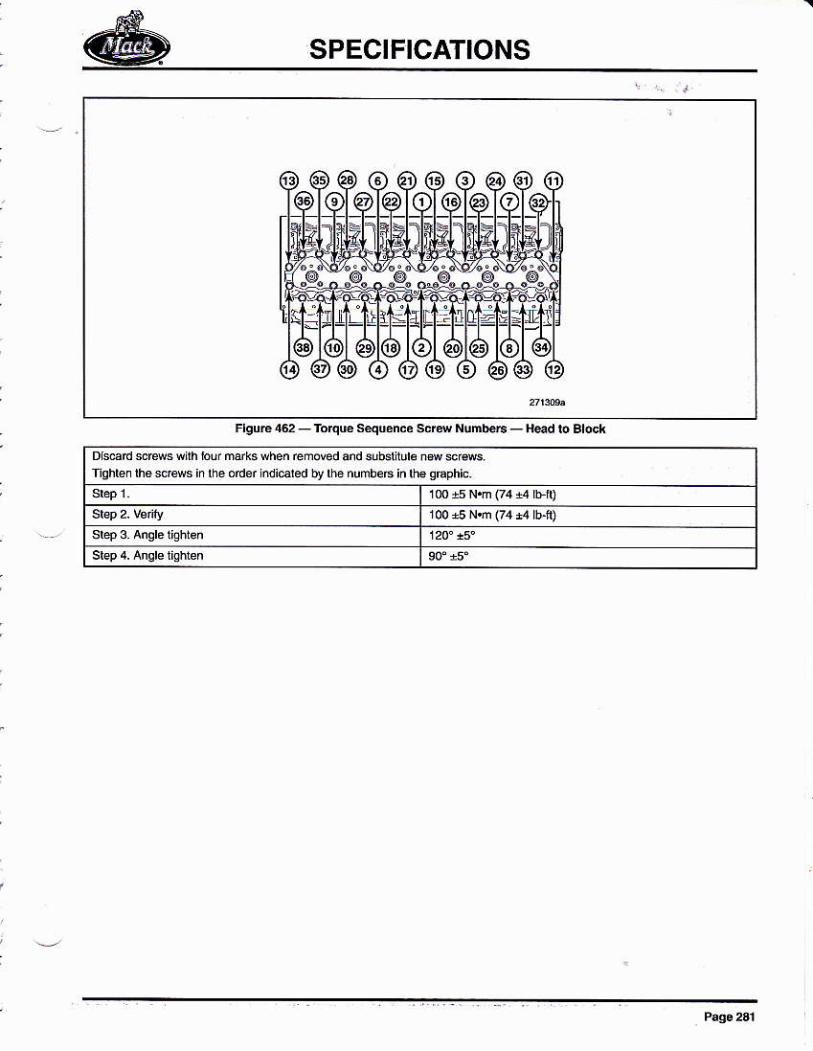
edb!lh6nunboÉinlh€oú9hio'
SPECIFICATIONS
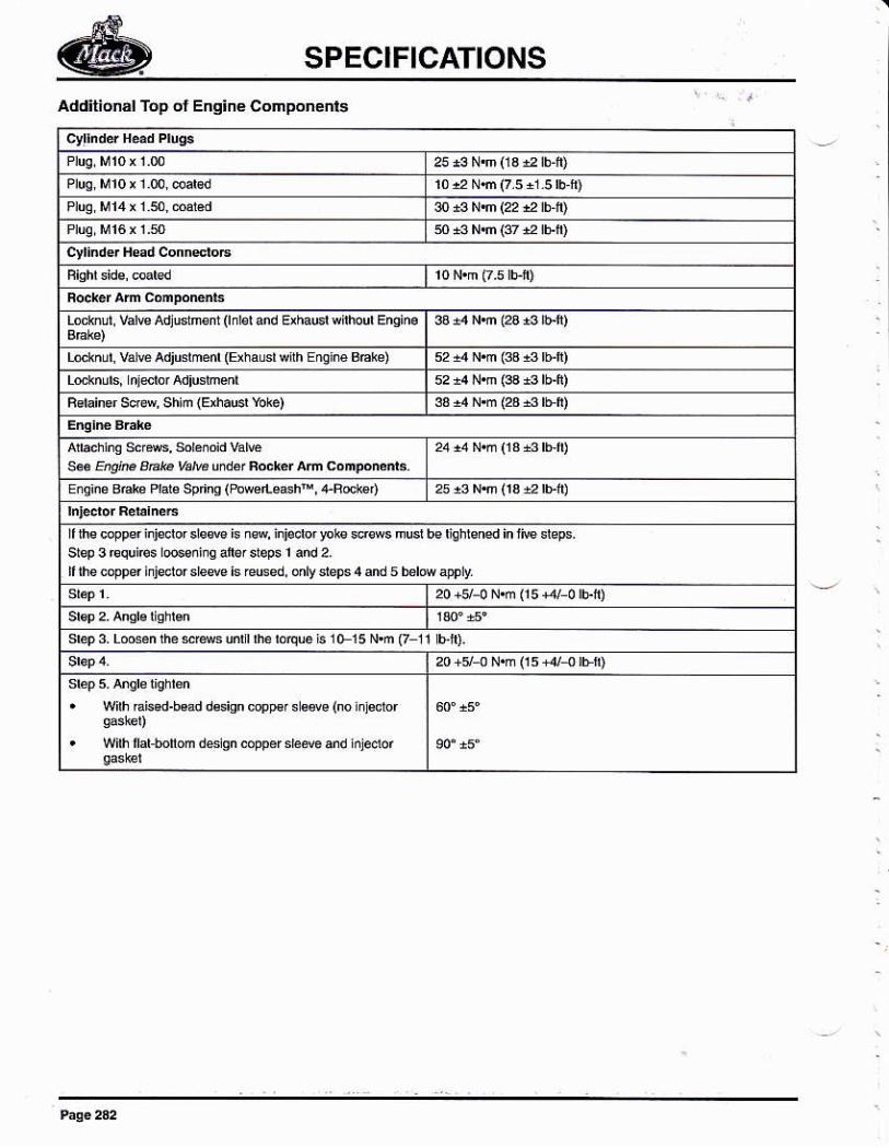
SPECIFICATIONS
Additiónál Top ol Enq¡ne Conponenli
Lodñu', var€ ¡dludmnt (nrd áíd ü
Lo.kñur. vá € Adjdmed (Erhaud wih EEin6 Bn¡s)
RdaiGr soa, shiñ {EúdÉr Yos)
úqús 8nb Pbb spnns (tu*e eashh, 4Rd€')
I rhs copper iiisdor sls@ is n4, iii6dü rlks smes mud be ¡lehrmed in ri6 deFs.
I rhe copper idedor de@ is rcused. onv *ps 4 d 5 bdfl aFly
uersr0 15 N.m (7 11 b,ft).
. Wirh Ebad.b€ad &sisn c@F s 8ee (no lnjsdor
. wih raÉ.nom desrsn coppef sh¿ve úd hjeclof
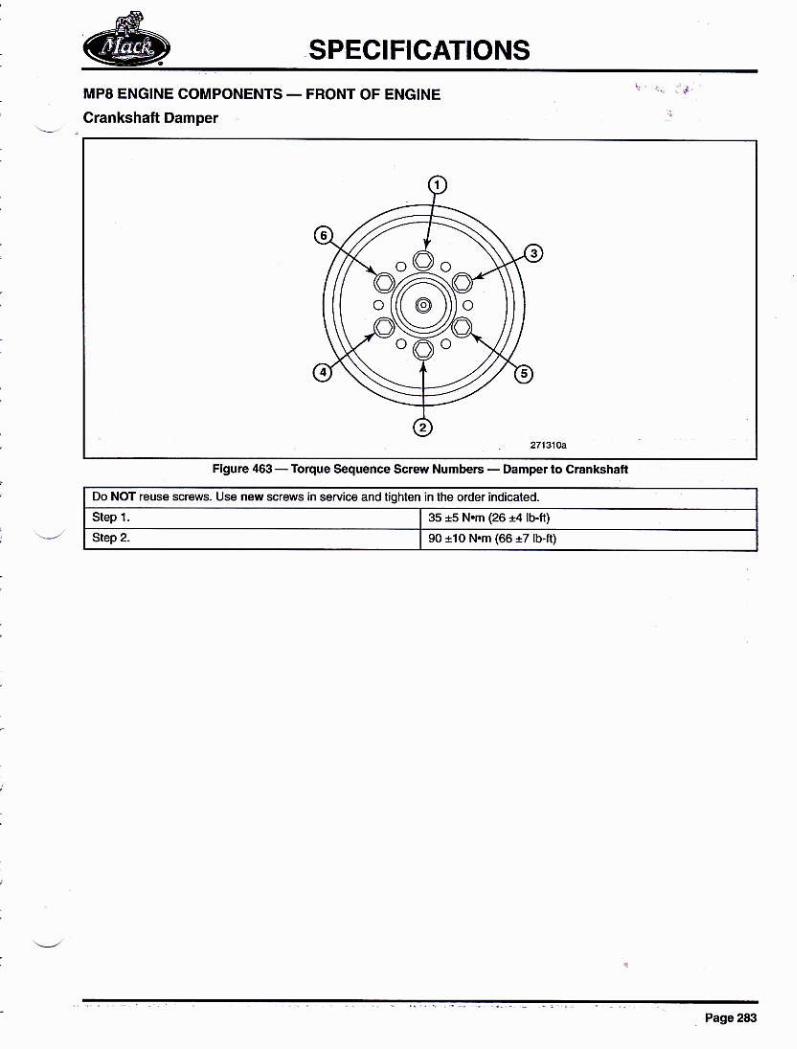
SPECIFICATIONS
üPA ENG¡NE COMPONENTS _ FFONT OF ENG¡NE
insaDi6andliohbn]nfuodefindi€I€d'
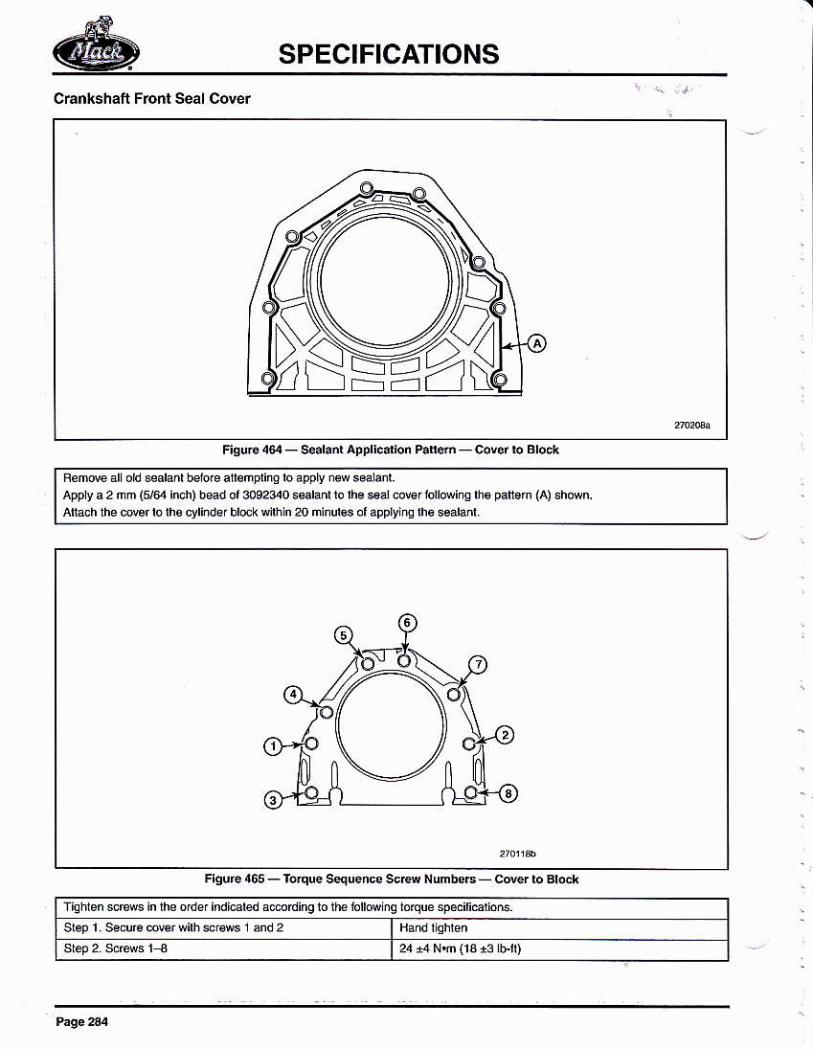
SPECIFICATIONS
Chnksháft Front Séal Cdér
appry a 2 mm (5,64 imh) b€d or @P e p*am (a) sh*n.n4njnftsola9glYimlfu$ahd
Flsuc165_rÚqEsgq$rcgscw
fighlenswsinlheodelindicaleda
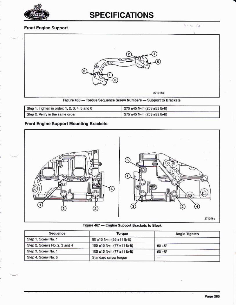
SPECIFICATIONS
sbp2W¡ilyhha9mo'd€l
Frent Erg¡né Support Mounl¡nq Bfackéts
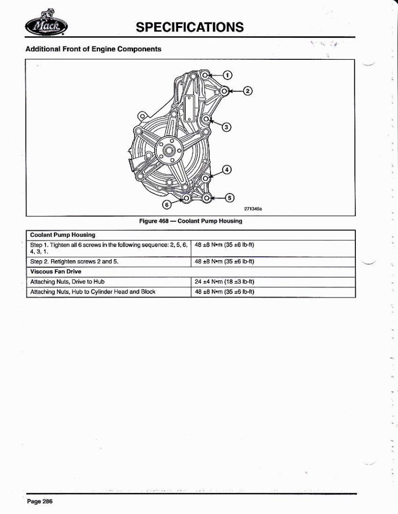
SPECIFICATIONS
Addil¡onál Frenl ol Enq¡né Componénls
Fhure @ - codd PumP Hruine
slep r . rishbn alr 6 srss in Írs rol is squoi€ 2, 5, 6,
AtehinqNub'nubbcvindsf!ۇdardBlock
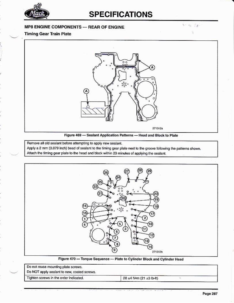
SPECIFICATIONS
MPA ENGINE COMPONE¡¡ÍS _ AEAR OF ENGINE
! ,. f¡ñiñg Gé¡r TE¡n Plate
FguE4Ú_kl'nlAppllc,donh
appry á 2 ñm (0.o4 ind,i b€d or sabñr b úe 'imiñs
q.ar prar€ nqr b rhsmdd@küúú,0mind6of4plying'116sdml
23 ¿4 N.n (2r ¡3 l'ft)
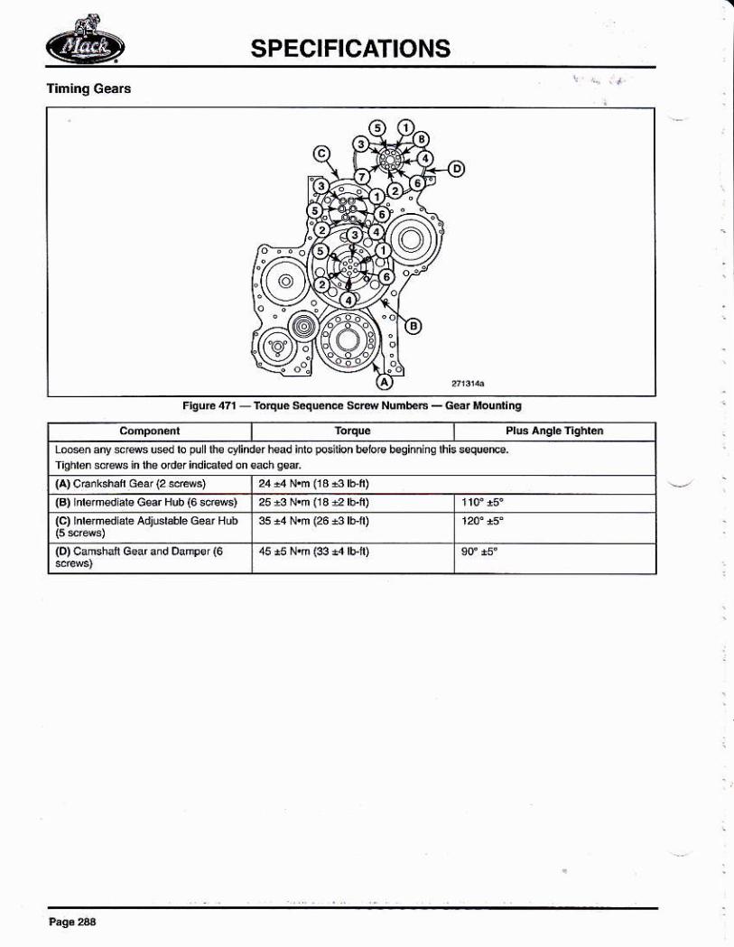
SPECIFICATIONS
l"q
bo*ñany$lemUedbpülmecyl
r ) cúkshrf GeÍ(2sffis)lBl rd€'r€d ab G8ar Hub (6 sdffi){c) rnré¡mád al¿ adjBr,hb er Hüb
lD) camshafi G€ar and oampsr (6
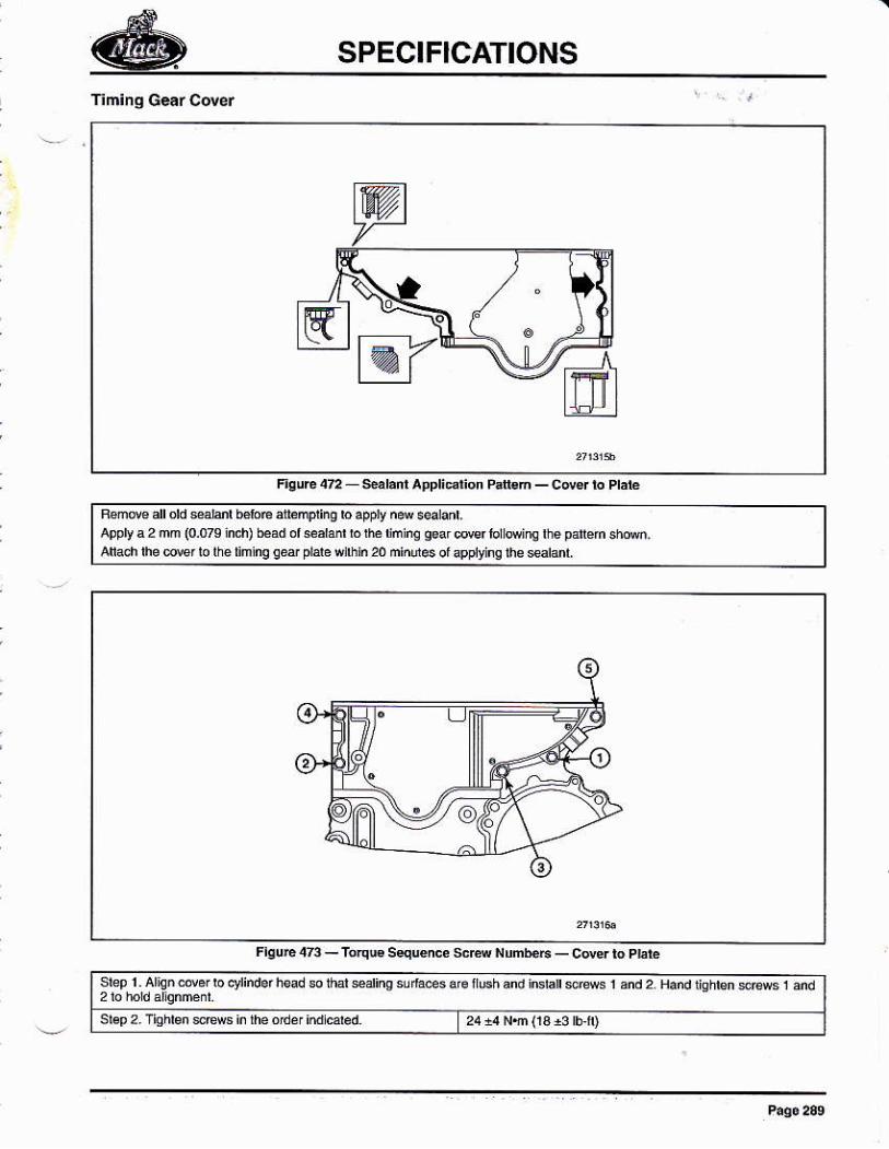
SPECIFICATIONS
appry a 2 nm (o.oru ind) be¡d d *aédúh,omhúsor4'r'tnerhesd'.
slag2'Tiohbnere$inlheo'ndiddad
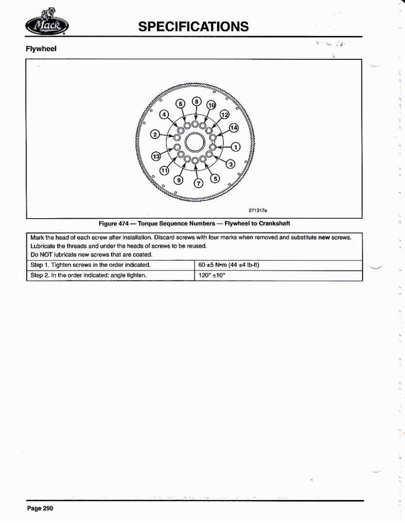
SPECIFICATIONS
b€E_Fltwh.cliocEn*.ha'l
sbFl¡qhbslesinlháodelindidd'sla2'lnfuor&flndidsd:8ml€tichl€n'
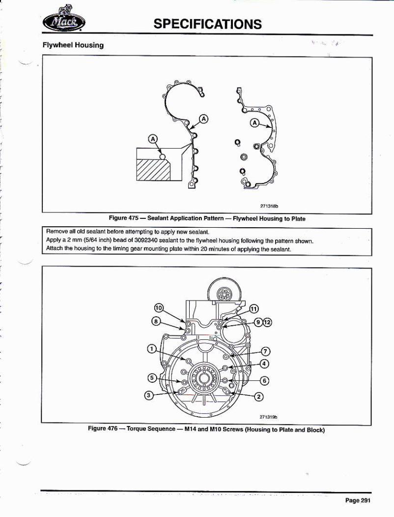
SPECIFICATIONS
hm_F'y{heelHG'ñgloPld.
Bamovsanoldglmiedear.npüappta2mm(564iich)bdd30o2sr0sear r ro üe r¡y,h*r h@ nq lor
nrins ptare {fth¡ñ 20 úrtuIés or apptirs rh¿ sdd
Fture 1?6 - ro4w s¿qrenó - h4 .ñd M1o se$ (Hosin, ro M¿ ,ñd stock)
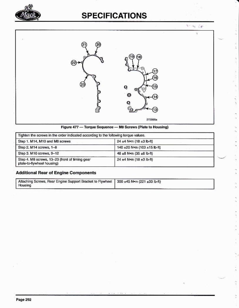
SPECIFICATIONS
qos
FsuE 4z - ro'que sqwne - M3 €cBs (Prft b HoGi4)
sbp4 M3 srs, 1+z (rmd or hinq q*r
Addit¡onal B€.r ol Enq¡né Componénl6
n sHbhoF aÉ | 30o 3s N,m {22r r3s rfi)
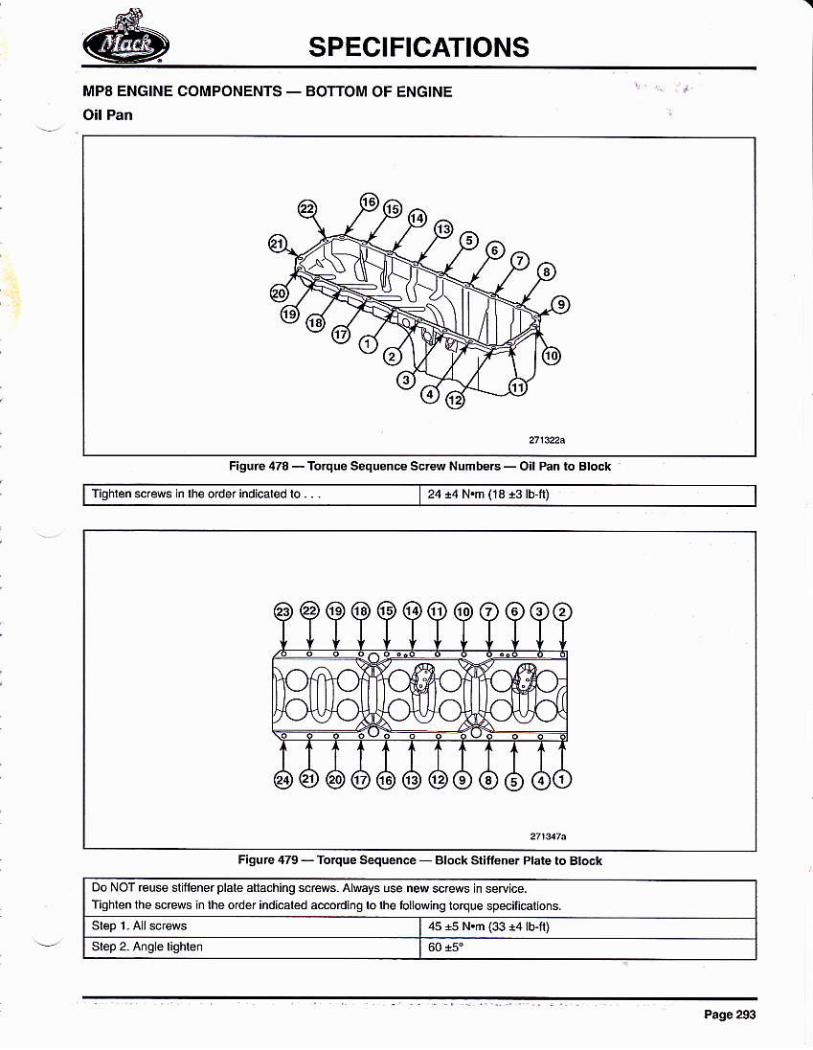
SPECIFICATIONS
r,P¡ EÑGINF COMPÓNENTS _
Figuc4ru_roqugs.qkm¿
DoNoTEusdfurefpldédtrhhgsc8sALlly3us.nÚ$Bsnsedice'
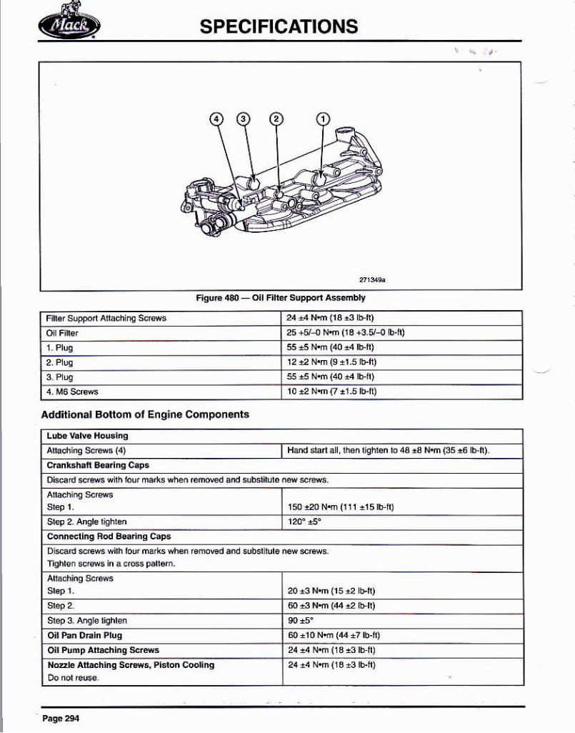
SPECIFICATIONS
Fiq¡[|30_ofElblsptsñAseñbly
25 +ei ñs (r s +3 5/-¡ b.fi)
Addit¡onal Bottom ol Eng¡ne Components
H¿ndsd¿! rbn'id{8n ro4313 Nn($,61ri).
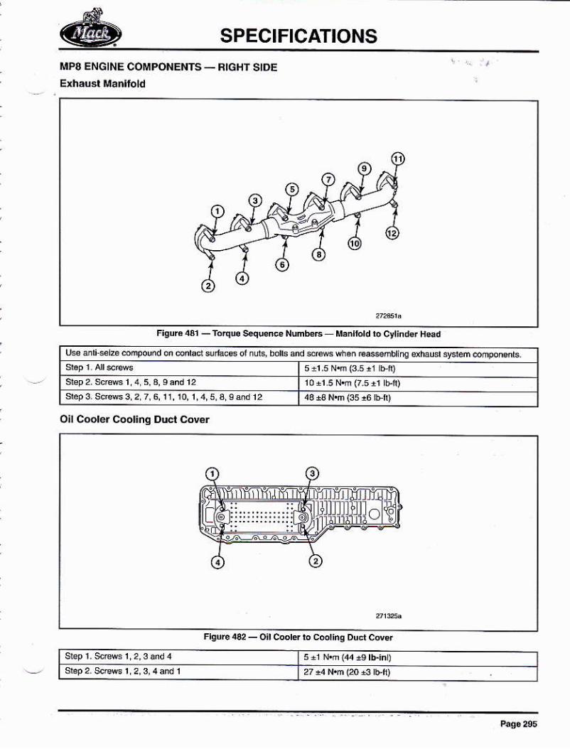
SPECIFICATIONS
I!IP8 ENGINE COMPONENTS _ RIGHf SIDE
r¡guld4l_TÓ4u.s4uen¿eNUm
c.$añblingshadsFiem@ñponeds'
O¡l C@ler Cool¡.q Duct cover
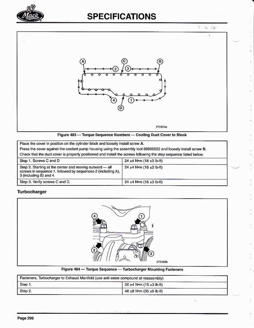
SPECIFICATIONS
HqúrceftqEsqu¿ncet{unb€
F¡gúÉ.€¡_To'quésqsncé
iúdd {sé m¡<.L. Mpoúd ar Éasmbu
00022 and ro6.t indan s@ B.ch@k thar üe dud @, L5 0@'t @
ere* in eqreme r b rored by squ¿ffi 2 (indud ns a).
srep 3 k¡t $reG c ánd o
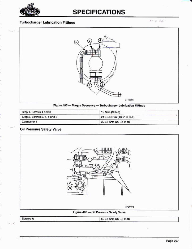
SPECIFICATIONS
Turbocharger L(br¡cal¡on FiÍ¡¡Os
rburcas róqm s€qud.. - ru
O¡l Presué Síery Vatve
FiguE4s_oilPE*Urc*brt¡vdE
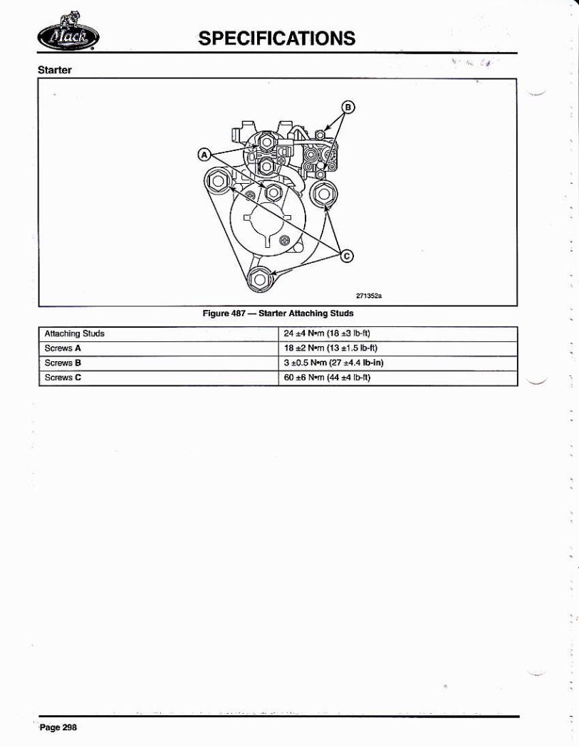
SPECIFICATIONS
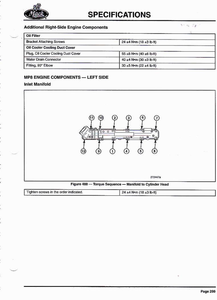
SPECIFICATIONS
Addilionál F¡ghl-S¡de Engire Conponents
MP8 ENGINE COMPONENTS _ LEFT SIDE
¡¡iloldlocylndef*d
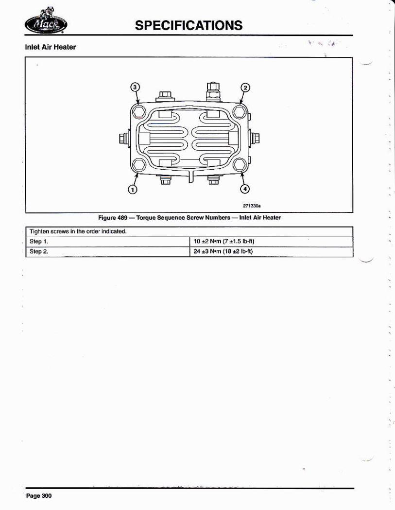
SPECIFICATIONS
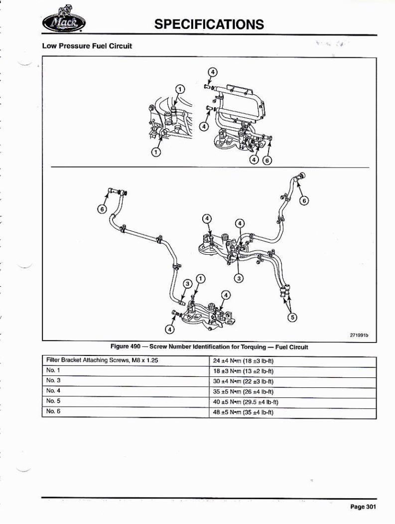
SPECIFICATIONS
f¡gué1s_scfuNmbelddtf
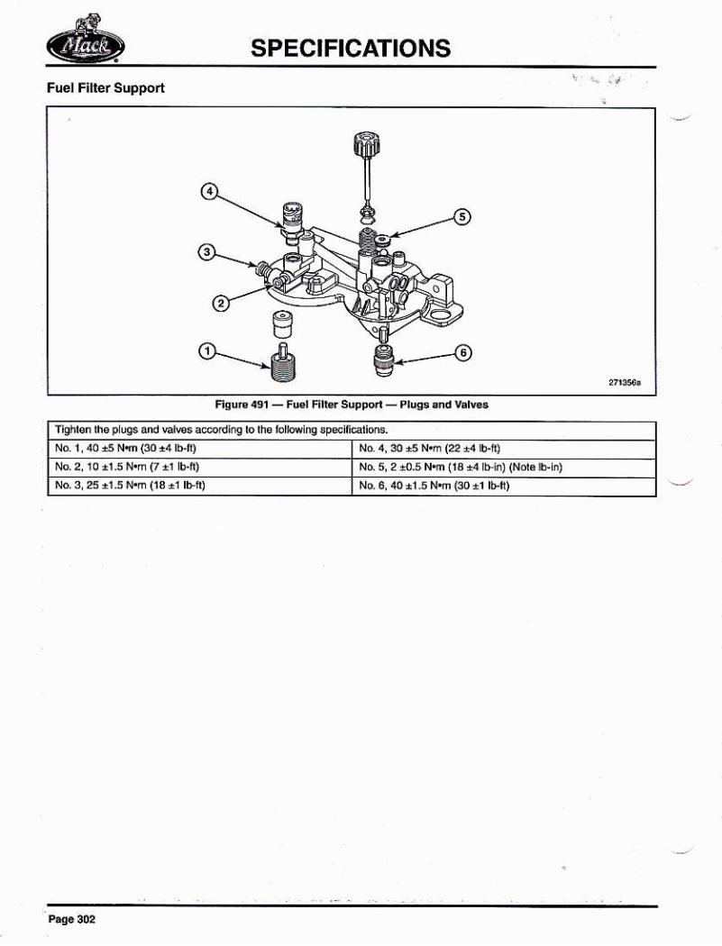
SPECIFICATIONS
Na 5, 2 {.5 Nn t3 +4 Lii) (Nd¿ !Eb)No 3,25,r.5 N.h fsal rFi) No 6, ¡0 r1 s Nn {30 11 rb-f)
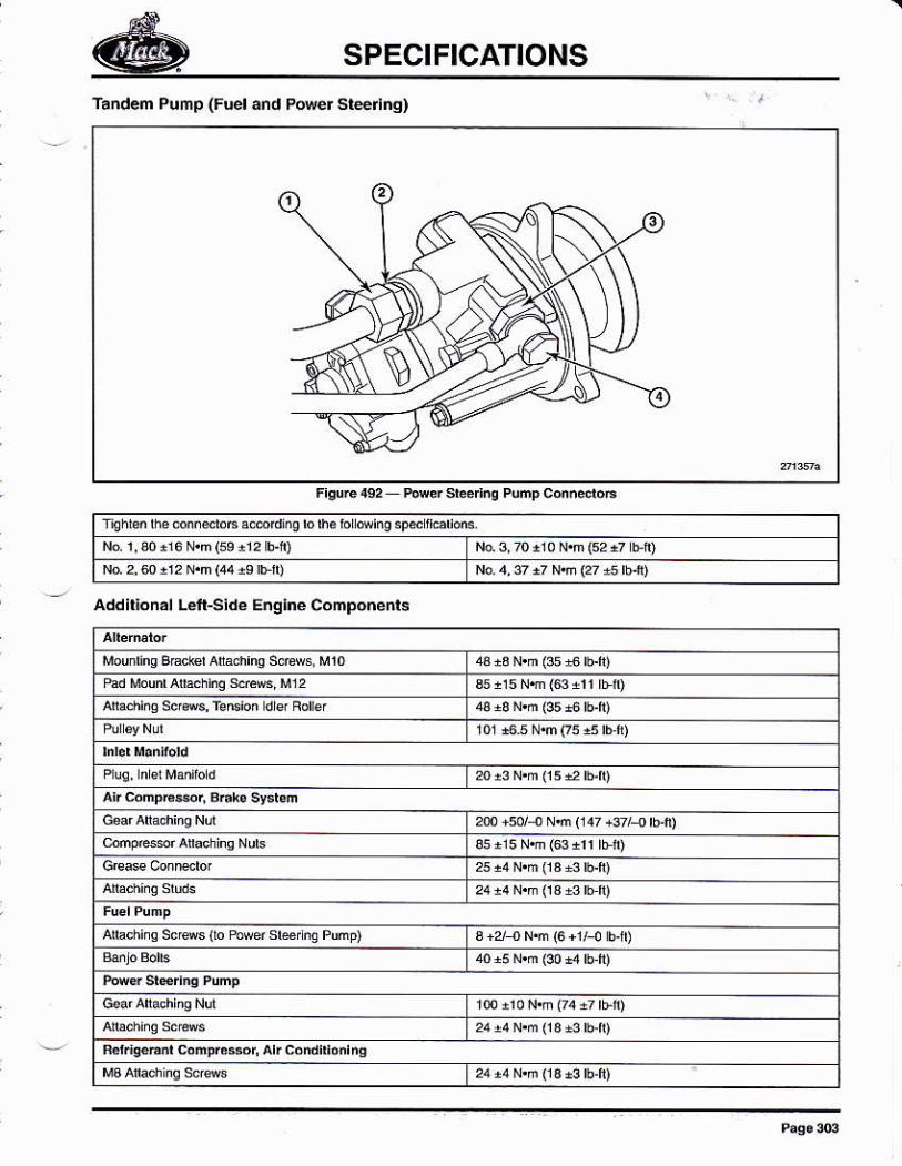
SPECIFICATIONS
Tandem Pump (Fuel and Porer Srerinq)
No 1,3o ri6 N.m (se i12 Elr) No.3, rc ri 0 N.m (s, +7 bf')N0 2, e !i2 N.n (44 is br)
Addil¡onál Léfi-Side Eng¡né Components
ar cómpreer, 3ñk. t*n2m +50/¡ N.ñ (147 +s7l{ br)
arhchino sc,e$ (ro tuwef sbrño Púmp)
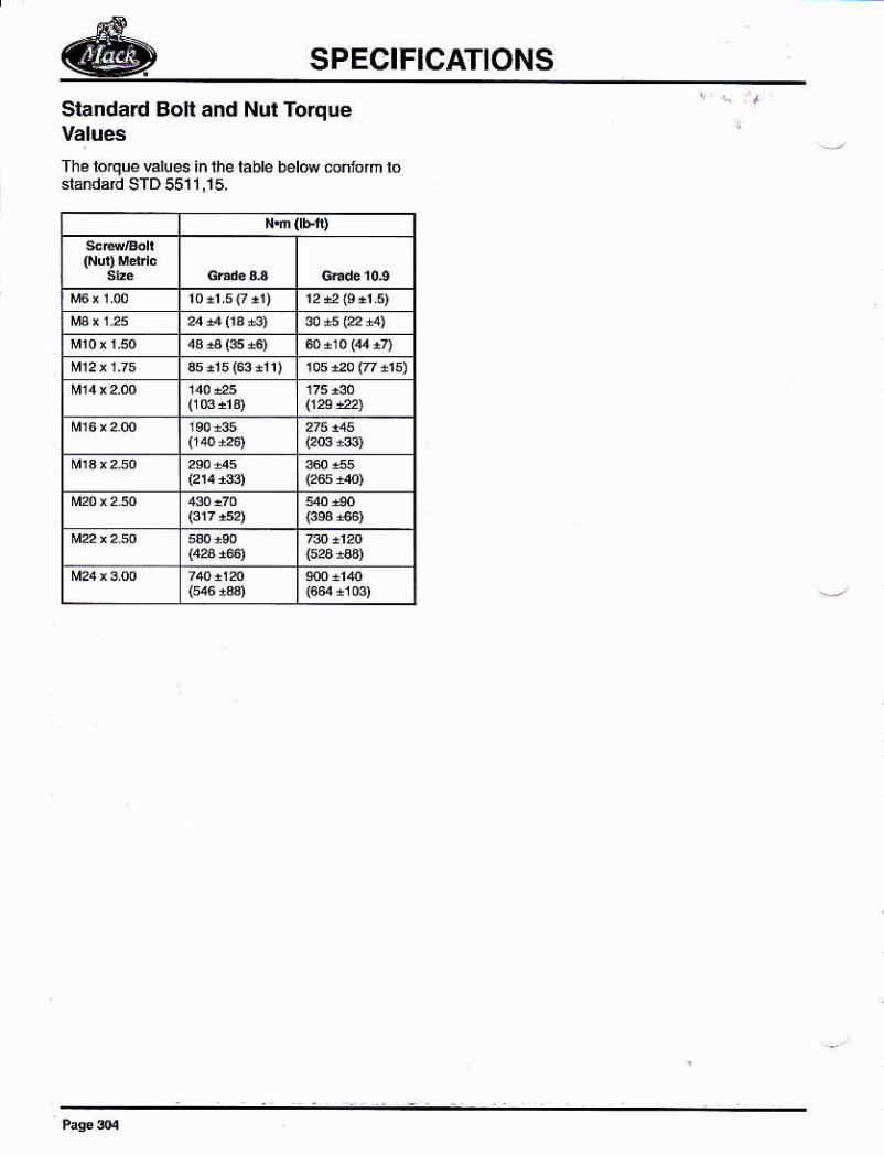
SPECIFICATIONS
Slandard Bolt and Nut TorqueValues
Thé rorque vaiues in the rable bd@ enJofm lo
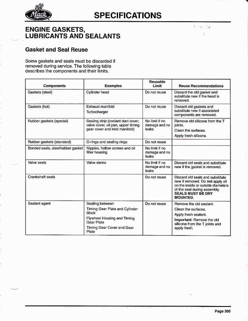
SPECIFICATIONS
ENGINE GASKETS,LUBRICANTS AND SEALANTS
Gasket and Seal Reuse
Some gaskers and eals musl be discarded ilr€m@d duing seryice, The lollwing tabledésribés ihé .ofnponánls and lhe¡rlimirs.
turñq r'F (mrad dud dMi
nerremMd Dondappvoit
nm ns G* P da .nd qrinds
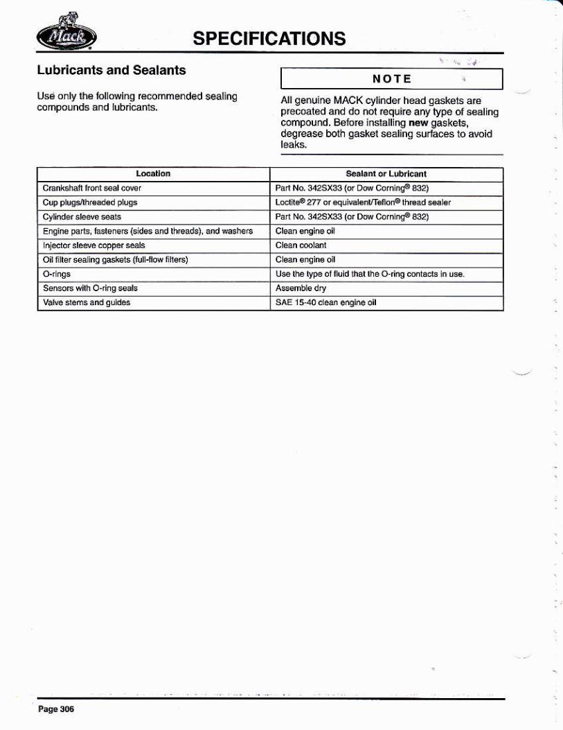
SPECIFICATIONS
Lubr¡canls and Sealants
Usá o¡ly l¡á lollNi¡g €@mmended sealingcompornds and lubricants.
NOTE
Allqenuine MACK cylinder head s6kéts a.¿precoal¿d and do nol equire arry lype of ssálingcoñpouñd. Béfor6 inslalling ns g$kets!degrcase bolh gaskei sealihg surlacés to áwid
P Na s2s¡33io' o@cdnnqoe)LÓdl¡p27?dfáq!v&nñdb¡olhts¿ds3lPrr Nd rrs€F DM cdnñq6 334
Eis'ne p¿ ds, r¿de is 6 (s dss and rheads) and @sh3 É
oilrlrer s inq qasksrs lturr-rm I h€E)
qry iNDH(
INDEX
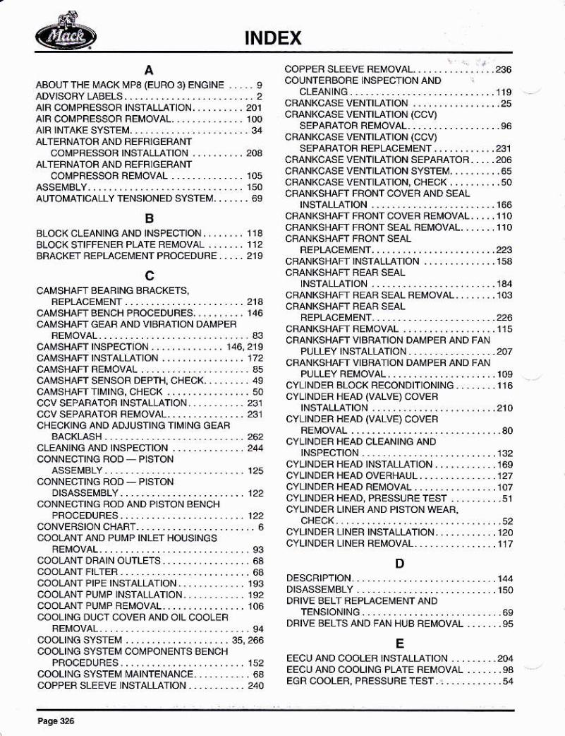
INDEX
AABOUT THE MACK MP3 (EUBO 3) ENGINEaDVrsoRY LABELS. . . . . . . . . . . . . . . . . . .
AIF COMPRESSOR INSTALLATION. .. . . .
AIR COMPRESSOF FEMOVAL..,.......arR rN-raKE sYsTEM.... . . ,. . ... . ,.. . ,
ALf EBNATOF AND REFRIGEMNTCOMPFESSOF INSTALTATON . . ... .
ALf ERNATOF ANO FEFF]GERANTCOMPFESSOR REMOVAL . .,,. . .. . .
ASSET\¡BLY, , ,.., ,.. , .... . .. . ... . ... .
AUTOMATICALLY TENSIONED SYSÍEM. .
BBLOCKCLEANINGANOINSPEC¡ION,,.,,,.. IlABLOCK S'IFFENER PLATE FEMOVAL....... 112BFACKEÍ FEPLACEMENTPFOCEDUFE ..., 219
c
CAMSHAFTAENCHPROCEDURES,..,,,,.,, 146
REMOVAI............................. 33cat\¡sHAFTtNsPECTtON.,,..,,..,.... 146,219CAMSHAFT INSÍALTATION . ...CA]\'SHAFf FEMOVAL......,.CAMSHAFT SENSOR DEPTH, CHECK, . . , . . . . . 49CAMSHAFT NMING, CHEC( ...CCV SEPABATOF INSTALLATION. , . . , , . . ..231ccvSEPARATOF FEMOVÁL............... 231
BACKT-ASH..
CONNECTINGROD PISTONASSEMBLY
otsÁssEMs1Y . . . . . . . . . . . . . . . . . . . _ .
CONNECTING FOD AND PISTON EENCHPFOCEDURES . . . . . . . . . . . - . . . . . . . . .
coNVERStON CHABT. . . . . . . . . . . . . . . . . .COOLANÍ AND PUMP INLEf HOUSJNGS
FEMOVAI.........................COOLANT DRAIN OUTLETS. . . . , . . . . . . . .COOLANÍ FILÍER .COOLANTPIPE INSIALIATION...,.,...,COOLANTPUI\¡P INSTALI-ATION.,...,,..COOLANTPUMF REMOV41........ ....COOLING DUC r COVEF AND OIL COOLE_F
coo1tNcsYsrEM...............,...,COOLING SYSTEM COMPONENTS BENCH
PROCEoURES . . . . . . . . . . . . . . . . . . . . .
COOLING SYSTEM MAINTENANCE. . .,. . .
COPPER SLEEVE NSTALLATION.. ..., .
COPPEF SLEEVE REMOVAL... .., .
COUNTEFBORE INSPECTION AND
CFANKCASE VENTILATIONCBANI<CASE VENf tLAltOñ (CCV)
SEPARATOF FEMOVÁI................CFANKCASE VENTILAÍ ION (CCV)
CFANKCASE VENTILATION SEPAFATOB. . . ,
CFANKCASEVENT]LATION SYSTEM,,,.,...CFANKC'.SEVEN¡LAÍION, CHECK.......,CFANKSHAFT FRONT COVEF AND SEAL
tNsT411ÁTrON .... ... . . ... . .... . ... ..CMNKSHAFT FFONI COVEF FEMOVAL....CRANKSHAFTFFONTSEALfiEMOVAL......CRANKSHAFT FFONÍSEAL
NSÍALTATTON . . . . . . . . . . . . ... .134CBANKSHAFI FEAF SEAL FEMOVAL..,.....103CRANKSHAN FE¡R SEAL
CFANKSHAFI REMOVAL . . ... .
CRANKSHAFT VIBRATION DAMPEB AND FANPULLEY INSTALLATION - 2OT
PULLEY REMOVAL. . . . . . . . . . . _.......CYL NDER BLOCK RECONDIT ONIÑG , . . , . .
CYL NDER HEAD (VALVE) COVEHtNsTA114TtON......................
CYLINDER HEAD (VALVE) COVEF
OVEBHAUL . . . . , . . . . .BEI\¡OVAL_.............PRESSUBE TEST . . , , . . .
oHECK . . . . . . . . . . . . . . . . . . . . . . . .
CYLINDEB LINEH FEMOVAL
DDESCR|PT|ON. . . . . . . . . . . . . . . . . . . . . .
DRIVE SELT BEPLACEMENÍ ANDTENS|ON|NG . . . . . . . . . . . . . . . . . . . .
DBIVE BELTS AND FAN BUB AEMOVAL .
EEECU ANO COOLEF
'NSIALLATION ., . .
EECU ANO COOLING PLAIE REMOVAL .
INDEX
ENGLNE CHECKS ANDTESTS......,,
SPECIF CATIONS (CRITICALFASfENERS). .... . .. ........
ENGINE COMPONENTS . . . . . . . . . , , . .
ENGINE COMPRESSION, TEST. . . . . . .
ENGINE DISASSEMBLY . . . . . , , . . , . . .
ENGINE FINAL PBEPABAT ON ANDoPEFAf|ONALCHECK..........,
ENGINE GASKETS, LUBFICANTS ANDSEALANTS....._...............
ENGINE INFORMATION PLAf EENGINE INSIALLATION. .., .... . .., .
EÑGINE LUBRICATION SYSTEM......ENGINE MANAGEI\,IENT SYSTEM . . . . .
ENGINE OPESAÍIONAL CHECK . . . . . .
ENGINE PFEHEAf EF/SPACEBtNsT4114TtON..................
FRONT ENGINE SUPPOFI FEMOVAL i,..FUELFILTERCHANGE..............,.,FUEL FILTER REPLACEMENT . . . , . . . . . , .
FUEL LINESAND F LÍEF HOUSING|NSTALLAT¡ON.............,...
GG¡.SKET AND SEALREUSE ,,...,GENEML.. . ... .. . ... . . .. . .. . .
GENERAL INFOFMAT]ON . , . . , . . .
GENEFAL INsIHUCTIONS , . . . . . .
GLOSSARY OF TERMS . . . . . . . . . .
IIN-CHASSIS PAFI/COMPONENf
PROCEOUAES . . . . . . . . . . . . .ENGTNE REMOVAL. . . . . . . . . . . . . . . . . . .
ENG1NE SERIAL NUMSER
ENGINE SYMPTOIú DIAGNOSIS . , . . . . . .
ENGINE WIFING HAFNESS FEMOVAL .
iÉiól
...153
EXHAUST MANIFOLD REI\¡OVAL. , ,EXHAUST PFESSUBE GOVEFNOR
INSTALLAT|ON......_........EXHAUST PRESSURE GOVEFNOR
FÉMOVA|. . . . . . . . . . . . . . . . . . .
INLE AND EXHAUST VALVE FEMOVAL. . .
INLET MANIFOI¡ INSTALLATION . . . . . . . .
INLFI MANIFOT.D REMOVAI , . , , . . . . . . , .
]NSPEC'ION............_..........NSTATLATTON . . . . . . . . . . . . . . . . . . . . . _ .
LLINEF HEIGHT MEASUREMENfLT]BFICANTS AND SEALANIS .. . ... ., . ..LUBFTCAI|ONSYSTEM.................LUBFICATION SYSIEM MAINTENANCE . .,
ltMACX MP8 EURO 3 ENGINE DES GN
FEATI]RES .. ..,MAIN BF¡R¡NG CAP INSIALLATION . , ,. .,MAIN BEAB¡NG CAP BEMOVAL. . ...., , ..]\'ATEFJAL AND DIMENSIONAL DAÍA . . . .MOUNTINGfHE ENGINE ON A REPAR
INJECTOF SLEEVE AEPLACEMENI . .. ...
REMOVAL .. .. ... ....
sfAND , . . . . . . . . . . _ . . . . . . . . . . . . .
MP8 ENGTNE SERVTCE TOOLS. . . . _ . . . . . . . . 303MP8 EUFO 3 ENGINECOMPONENT LOCATION
SYsTEM... .. .....EXHAUST PRESSUBE GOVEFNOR,
EXPLANATION OF NUI\¡EAEAL CODE. . . .
F
rNsT411ÁTtON.....................F LIEF ELEMENÍ INSTALLATION . , , . . . .F LTEFS ANO MISCELLANEOUS
COMPONENTS INSTALLATION . , , . . . .
F NAL S-IEPS. .... . .. . . .. .. 220,243,
rNsT4114TtON.....................FLYW-IEEL AND PILOf BEAR]NG
BEMOVAL.......FLYWHEEL BENCH PFOCFDURES ....,,FLYI'V}IEEL HOUSING INSTALLATIOÑ . . ..FLYWHEEL HOUSING FEMOVAL...,..,.FLYWHEEL HOUSING FUNOUT, CHECX,,FLYWHEEL RING GEAR REPLACEMENT..FRONT ENGINE SUPPOFT
vtEws . . . . . . . . . . . . . . . . . . .
MP3 EUFO 3 ENGINE MECHAÑICALSPECIFICAflONS..,..,.........
MP3 EUFO 3 ENGINE MODELrDENfrFrcAf oN................
MP8 EIJFO 3 ENGINESETUPAND
INDEX
NNEOPRENE SEAL INSTALLAT¡ONNEOPRENE SEAL REMOVAL. , , , . . , , , , . , , . , 226
RFEBUILT ENGINE RUN]N PROCEDURES],,..263REMOVÁ1........................FEMOVING ENGINE FROM ENGINESTAND...212
oOILAND FILTER CHANGE PROCEDUFE ,....OIL COOLEB AND COOLING DUCT COVER
|NSTALIATTON.,,.,,.,,,..,,,..,,,..,.orlcooLERRECONDIÍ|ONjNG..-.........orLcooLEF,pFEssuFEfEsf ............
tNsTALLAftON.................FOCKEF AFM SHAFÍ ASSEMBLY.....ROCKEF AFM SHAFÍBENCH
PROCEDURES ......, .,ROCKER AFM SHAFT DISASSEMBLY . ,
ROCKEFARM SHAFTREMOVAL,...,,ROCKERARM,CHECK..............
REMOVAL.O L FILLEF PIPE AND DIPSTICK PIPE
TNSfaLLATON_....................... 139OILFILTEF HOUSING IÑSTALLATION .. . 196OIL F]LTEF VALVE HOUSING REMOVAL . . .. .. 93oTL LEVEL CHECK. -...... -...OIL PAN INSTALLATION.. ... J37orl PAN FEMOVAL. -.........OIL PUMP AND SLOCKSTIFFENER PLATE
NST41IÁTpN........................ 164OILPI-IMP INSIALLATION.......OILPUMP PIPES AND STBAINEF
OILPUMP FEMOVAL. -...... -,O]LPUMP FEPLACEMENT (lN CHASSIS)..,., 231
vaLVEREPLACEMENÍ ................. 22rO L THEBIIOSTAT VALVE
ñEPLACÉMENI...................-... 222
PPISfON AND CONNECTING FOD
aSSEMBLY NSTALLAT]ON.............. 161PISTON AND CONNECTING FOD
assEMBLYFEMOVAL.................. 113PISTON COOLING SPFAY NOZLE
FEMoVAL'.,''',''.'''.'''.,,'..,'''' 117PISTONINSPECTIONANDCLEANING....... 123PISTON RING INSPECT ON ANO
BEP14CEMENT....................... 124POWER TAKE OFF (PTO) ASSEMBLY
POWERTAKE.OFF INSfALIATION,...,...,. 139POWERLEASI]Iú ENGINE BRAKEPFEL|M|NAFY STEPS. . _...... 213,236,244,250
sSEAL INSIALLATION . . . . -....,SEALREMOVAL..............SEFVICE PRECAUTIONS SUMMAFY. . , .,..10SEFVICE PROCEOLJHES AND TOOL L-ISACE . . - .3SPEC|ALTOOL...............SPECTALfOOLS........¡6,72,76,1¿4.153,214,
223, 226,231,249,254SPEC]AL TOOLS FOR ENGINE OVERHAUL. . . .3O3STANDARD BOLf AND NUf TOFOUE
vaLUES . . . . . . . . . . . . . . . _ . . . . . . . . . . . . . . 304STARTER INSTALLATION...,,.STAFTEF FEMOVAL , ..., . ,..,
TTANDEM PUMP (FUELANO POWEF
STEEHTNG)rNSr4114TlON...,...,......202TANOEM PUMP (FUELAND POWEB
STEEF|NG)8EMOV41........ .........100TEFLON@SFAL INSTATLATION .TEFLON@ SEAL FEMOVAL , .THERMOSTAT AND COVEF
NSf4r14TtON,.......................193THEBMOSIAf ANDCOVEF FEMOVAL..,,...106THEFMOSTAf. CHECK . ... . ...TIMING GEAF COVER INSTALLATION..... ..19OT]MING GEAF COVEB REMOVALTIMING GEAH PLATE INSTALLATION....,....163T]MING GEAF PLATE REMOVAL.., . ..,T]MING GEAF TFAIN INSTALTATIT]MING GEAF IFAIN FEMOVAL.TOOLS AND EOUIPMENÍ ...TFOUBLESNOOTING TECHNIOUrIFBOCHARGER.....,.......TURAOCHARGEF INSTALLATION
INDEX
uuNfT TNJECTOR CLEAN|NG,,,..............244uNtf tNJEcToR tNsfA!¡TtoN ... _... _.... _176UNITINJECTOR BEMOVAL.....
vVAIVE AND UN¡T INJECÍOR
4DJUSTMENT .. .... ,..,.... . , .. . _... . .2s6VALVE GUIDE REPIACEMENT .
vaLVE rNsralra¡oN. . . . . . . .: . lt : iVALVE SPFING INSPECTIOÑ.. ... , !.VALVE STEM HEIGHT MEASUFEMENf
PBOCEOUFE ...., , ,. .... ... _ _.. .. . . _.VALVE SÍEM SEAL REPLACEMEI,¡T . . . . .VALVE YOKE (BFIDGE] INSTALLATIOI¡VALVEYOKE(BF|DGE FEMOVA! . _......... 35
WvalvE GUTDE WEAF_ CHÉCK... wJRtNG HABNESS ¡NSTALLA¡ON . . . . , . , , . . m9vÁrvE NsP€cTloN, . , . , , , . . . . ............142