motion terminal vtem - festo.com · 2.3 motion apps ... english 2 function 2.1 general remarks the...
TRANSCRIPT

Motion Terminal
VTEM
Description
Function
Parameterisation
8071728
2017-12
[8071730]

VTEM
2 Festo – VTEM-Func+Par-EN – 2017-12 –
Translation of the original instructions
VTEM-Func+Par-EN
Firefox® is a registered trademark of its respective trademark holder in certain countries.

VTEM
Festo – VTEM-Func+Par-EN – 2017-12 – English 3
Table of contents
1 About this document 6. . . . . . . . . . . . . . . . . . . . . . . . . . . . . . . . . . . . . . . . . . . . . . . . . . . . . . . . . . . . . . . . . . . . .
1.1 Further applicable documents 6. . . . . . . . . . . . . . . . . . . . . . . . . . . . . . . . . . . . . . . . . . . . . . . . . . . . . . . . . . . . . .
1.2 Target group 6. . . . . . . . . . . . . . . . . . . . . . . . . . . . . . . . . . . . . . . . . . . . . . . . . . . . . . . . . . . . . . . . . . . . . . . . . . . .
1.3 Product version 6. . . . . . . . . . . . . . . . . . . . . . . . . . . . . . . . . . . . . . . . . . . . . . . . . . . . . . . . . . . . . . . . . . . . . . . . .
1.3.1 Product labelling 7. . . . . . . . . . . . . . . . . . . . . . . . . . . . . . . . . . . . . . . . . . . . . . . . . . . . . . . . . . . . . . . . . .
2 Function 9. . . . . . . . . . . . . . . . . . . . . . . . . . . . . . . . . . . . . . . . . . . . . . . . . . . . . . . . . . . . . . . . . . . . . . . . . . . . . . .
2.1 General remarks 9. . . . . . . . . . . . . . . . . . . . . . . . . . . . . . . . . . . . . . . . . . . . . . . . . . . . . . . . . . . . . . . . . . . . . . . . .
2.1.1 Product design 9. . . . . . . . . . . . . . . . . . . . . . . . . . . . . . . . . . . . . . . . . . . . . . . . . . . . . . . . . . . . . . . . . . .
2.1.2 Display components 11. . . . . . . . . . . . . . . . . . . . . . . . . . . . . . . . . . . . . . . . . . . . . . . . . . . . . . . . . . . . . . .
2.1.3 Control components 13. . . . . . . . . . . . . . . . . . . . . . . . . . . . . . . . . . . . . . . . . . . . . . . . . . . . . . . . . . . . . . .
2.1.4 Connection components 13. . . . . . . . . . . . . . . . . . . . . . . . . . . . . . . . . . . . . . . . . . . . . . . . . . . . . . . . . . . .
2.1.5 Definition of direction of movement/position of the drive 15. . . . . . . . . . . . . . . . . . . . . . . . . . . . . . . . .
2.2 WebConfig user interface 16. . . . . . . . . . . . . . . . . . . . . . . . . . . . . . . . . . . . . . . . . . . . . . . . . . . . . . . . . . . . . . . . . .
2.2.1 Manual override 16. . . . . . . . . . . . . . . . . . . . . . . . . . . . . . . . . . . . . . . . . . . . . . . . . . . . . . . . . . . . . . . . . .
2.3 Motion apps 17. . . . . . . . . . . . . . . . . . . . . . . . . . . . . . . . . . . . . . . . . . . . . . . . . . . . . . . . . . . . . . . . . . . . . . . . . . . .
2.3.1 Motion app ID 17. . . . . . . . . . . . . . . . . . . . . . . . . . . . . . . . . . . . . . . . . . . . . . . . . . . . . . . . . . . . . . . . . . . .
2.3.2 Licences 17. . . . . . . . . . . . . . . . . . . . . . . . . . . . . . . . . . . . . . . . . . . . . . . . . . . . . . . . . . . . . . . . . . . . . . . . .
2.3.3 System and application parameters 17. . . . . . . . . . . . . . . . . . . . . . . . . . . . . . . . . . . . . . . . . . . . . . . . . .
2.3.4 Setpoint and actual values 23. . . . . . . . . . . . . . . . . . . . . . . . . . . . . . . . . . . . . . . . . . . . . . . . . . . . . . . . . .
2.3.5 Waiting time between Motion apps 23. . . . . . . . . . . . . . . . . . . . . . . . . . . . . . . . . . . . . . . . . . . . . . . . . . .
2.4 Communication between PLC and Motion Terminal 24. . . . . . . . . . . . . . . . . . . . . . . . . . . . . . . . . . . . . . . . . . . . .
2.4.1 Numerical representation 24. . . . . . . . . . . . . . . . . . . . . . . . . . . . . . . . . . . . . . . . . . . . . . . . . . . . . . . . . . .
2.4.2 Structure of the process data when running a Motion app 24. . . . . . . . . . . . . . . . . . . . . . . . . . . . . . . .
2.4.3 Running a Motion app 27. . . . . . . . . . . . . . . . . . . . . . . . . . . . . . . . . . . . . . . . . . . . . . . . . . . . . . . . . . . . .
2.4.4 Transfer mode 29. . . . . . . . . . . . . . . . . . . . . . . . . . . . . . . . . . . . . . . . . . . . . . . . . . . . . . . . . . . . . . . . . . . .
2.5 Motion App #01: Directional control valve functions 36. . . . . . . . . . . . . . . . . . . . . . . . . . . . . . . . . . . . . . . . . . . .
2.5.1 Functional description 36. . . . . . . . . . . . . . . . . . . . . . . . . . . . . . . . . . . . . . . . . . . . . . . . . . . . . . . . . . . . .
2.5.2 Sensors required 36. . . . . . . . . . . . . . . . . . . . . . . . . . . . . . . . . . . . . . . . . . . . . . . . . . . . . . . . . . . . . . . . .
2.5.3 System parameters used 36. . . . . . . . . . . . . . . . . . . . . . . . . . . . . . . . . . . . . . . . . . . . . . . . . . . . . . . . . . .
2.5.4 Application parameters used 36. . . . . . . . . . . . . . . . . . . . . . . . . . . . . . . . . . . . . . . . . . . . . . . . . . . . . . . .
2.5.5 Set values 36. . . . . . . . . . . . . . . . . . . . . . . . . . . . . . . . . . . . . . . . . . . . . . . . . . . . . . . . . . . . . . . . . . . . . . .
2.5.6 Feedback values 39. . . . . . . . . . . . . . . . . . . . . . . . . . . . . . . . . . . . . . . . . . . . . . . . . . . . . . . . . . . . . . . . . .
2.6 Teach-in run 42. . . . . . . . . . . . . . . . . . . . . . . . . . . . . . . . . . . . . . . . . . . . . . . . . . . . . . . . . . . . . . . . . . . . . . . . . . . .
2.6.1 Prerequisites for starting the teach-in run 42. . . . . . . . . . . . . . . . . . . . . . . . . . . . . . . . . . . . . . . . . . . . .
2.6.2 Selection of the teach-in run mode 42. . . . . . . . . . . . . . . . . . . . . . . . . . . . . . . . . . . . . . . . . . . . . . . . . . .
2.6.3 Controlling the manual teach-in run 43. . . . . . . . . . . . . . . . . . . . . . . . . . . . . . . . . . . . . . . . . . . . . . . . . .
2.6.4 End-position sensing 43. . . . . . . . . . . . . . . . . . . . . . . . . . . . . . . . . . . . . . . . . . . . . . . . . . . . . . . . . . . . . .
2.6.5 State of teach-in run 44. . . . . . . . . . . . . . . . . . . . . . . . . . . . . . . . . . . . . . . . . . . . . . . . . . . . . . . . . . . . . . .
2.6.6 Sequence of teach-in run 44. . . . . . . . . . . . . . . . . . . . . . . . . . . . . . . . . . . . . . . . . . . . . . . . . . . . . . . . . . .
2.6.7 Saving the teach-in data 44. . . . . . . . . . . . . . . . . . . . . . . . . . . . . . . . . . . . . . . . . . . . . . . . . . . . . . . . . . . .
2.7 Diagnostics options 45. . . . . . . . . . . . . . . . . . . . . . . . . . . . . . . . . . . . . . . . . . . . . . . . . . . . . . . . . . . . . . . . . . . . . .
2.7.1 LED display components 45. . . . . . . . . . . . . . . . . . . . . . . . . . . . . . . . . . . . . . . . . . . . . . . . . . . . . . . . . . .
2.7.2 Diagnostic interface 48. . . . . . . . . . . . . . . . . . . . . . . . . . . . . . . . . . . . . . . . . . . . . . . . . . . . . . . . . . . . . . .
2.7.3 Diagnostics channel in transfer mode 49. . . . . . . . . . . . . . . . . . . . . . . . . . . . . . . . . . . . . . . . . . . . . . . . .

VTEM
4 Festo – VTEM-Func+Par-EN – 2017-12 – English
3 Parameterisation 54. . . . . . . . . . . . . . . . . . . . . . . . . . . . . . . . . . . . . . . . . . . . . . . . . . . . . . . . . . . . . . . . . . . . . . . .
3.1 Setting system and application parameters 54. . . . . . . . . . . . . . . . . . . . . . . . . . . . . . . . . . . . . . . . . . . . . . . . . . .
3.1.1 Prerequisites 54. . . . . . . . . . . . . . . . . . . . . . . . . . . . . . . . . . . . . . . . . . . . . . . . . . . . . . . . . . . . . . . . . . . . .
3.1.2 Procedure 54. . . . . . . . . . . . . . . . . . . . . . . . . . . . . . . . . . . . . . . . . . . . . . . . . . . . . . . . . . . . . . . . . . . . . . .
3.2 Reading out system and application parameters 55. . . . . . . . . . . . . . . . . . . . . . . . . . . . . . . . . . . . . . . . . . . . . . .
3.2.1 Prerequisites 55. . . . . . . . . . . . . . . . . . . . . . . . . . . . . . . . . . . . . . . . . . . . . . . . . . . . . . . . . . . . . . . . . . . . .
3.2.2 Procedure 55. . . . . . . . . . . . . . . . . . . . . . . . . . . . . . . . . . . . . . . . . . . . . . . . . . . . . . . . . . . . . . . . . . . . . . .
3.3 Saving parameterisation as persistent data 57. . . . . . . . . . . . . . . . . . . . . . . . . . . . . . . . . . . . . . . . . . . . . . . . . . .
3.4 Changing parameter set 57. . . . . . . . . . . . . . . . . . . . . . . . . . . . . . . . . . . . . . . . . . . . . . . . . . . . . . . . . . . . . . . . . . .
A Technical appendix 59. . . . . . . . . . . . . . . . . . . . . . . . . . . . . . . . . . . . . . . . . . . . . . . . . . . . . . . . . . . . . . . . . . . . . .
A.1 Technical data 59. . . . . . . . . . . . . . . . . . . . . . . . . . . . . . . . . . . . . . . . . . . . . . . . . . . . . . . . . . . . . . . . . . . . . . . . . . .
A.1.1 General information 59. . . . . . . . . . . . . . . . . . . . . . . . . . . . . . . . . . . . . . . . . . . . . . . . . . . . . . . . . . . . . . .
A.1.2 Power supply 59. . . . . . . . . . . . . . . . . . . . . . . . . . . . . . . . . . . . . . . . . . . . . . . . . . . . . . . . . . . . . . . . . . . . .
A.1.3 Operating and environmental conditions 59. . . . . . . . . . . . . . . . . . . . . . . . . . . . . . . . . . . . . . . . . . . . . .
A.1.4 Input modules 60. . . . . . . . . . . . . . . . . . . . . . . . . . . . . . . . . . . . . . . . . . . . . . . . . . . . . . . . . . . . . . . . . . . .
B Glossary 61. . . . . . . . . . . . . . . . . . . . . . . . . . . . . . . . . . . . . . . . . . . . . . . . . . . . . . . . . . . . . . . . . . . . . . . . . . . . . . .
C Supported peripherals 62. . . . . . . . . . . . . . . . . . . . . . . . . . . . . . . . . . . . . . . . . . . . . . . . . . . . . . . . . . . . . . . . . . .
C.1 Supported CPX bus nodes 62. . . . . . . . . . . . . . . . . . . . . . . . . . . . . . . . . . . . . . . . . . . . . . . . . . . . . . . . . . . . . . . . .
C.2 List of supported drives 62. . . . . . . . . . . . . . . . . . . . . . . . . . . . . . . . . . . . . . . . . . . . . . . . . . . . . . . . . . . . . . . . . . .
D Diagnostics using transfer mode 68. . . . . . . . . . . . . . . . . . . . . . . . . . . . . . . . . . . . . . . . . . . . . . . . . . . . . . . . . . .
D.1 Error in basic system 68. . . . . . . . . . . . . . . . . . . . . . . . . . . . . . . . . . . . . . . . . . . . . . . . . . . . . . . . . . . . . . . . . . . . .
D.2 Application-specific malfunction 70. . . . . . . . . . . . . . . . . . . . . . . . . . . . . . . . . . . . . . . . . . . . . . . . . . . . . . . . . . . .
D.3 Sensor error 73. . . . . . . . . . . . . . . . . . . . . . . . . . . . . . . . . . . . . . . . . . . . . . . . . . . . . . . . . . . . . . . . . . . . . . . . . . . .
E Licences 74. . . . . . . . . . . . . . . . . . . . . . . . . . . . . . . . . . . . . . . . . . . . . . . . . . . . . . . . . . . . . . . . . . . . . . . . . . . . . . .

1 About this document
Festo – VTEM-Func+Par-EN – 2017-12 – English 5
1 About this document
This document describes the function and parameterisation of the product stated in the title. Safe use of the
product is described in a separate document (� 1.1 Further applicable documents).
1.1 Further applicable documents
Document Contents
Assembly instructions for Motion Terminal CPX, VTEM
(CPX_VTEM-…)
Instructions and important notes on the mounting of
the Motion Terminal VTEM with connected CPX terminal
Instructions for use of the Motion Terminal VTEM
(VTEM-...)
Instructions on safe use and important notes on
handling, installation, commissioning and maintenance
of the Motion Terminal VTEM
Description of the Motion Terminal VTEM, Motion app ...
(VTEM-MA…-…)
Detailed description of the Motion apps for the
Festo�Motion Terminal VTEM
CPX system description
(P.BE-CPX-SYS-…)
Information on the complete system of the CPX terminal
Tab. 1.1
For all available product documentation � www.festo.com/pk
1.2 Target group
This document is intended for qualified personnel. Experience with electrical and pneumatic control systems is
required in order to understand this documentation.
1.3 Product version
This document refers to the following product versions:
Product Version
VTEM-… Motion Terminal VTEM, revision 01 or later
CTMM-S1-C Controller for the Motion Terminal VTEM, revision 01 or later
Firmware Firmware for the controller CTMM, version 4.0.2 or later
VEVM-S1-27-… Valve for Motion Terminal VTEM, revision 01 or later
CTMM-S1-D-8E-M8-3 Digital input module for Motion Terminal VTEM, revision 01 or later
CTMM-S1-A-8E-A-M8-4 Analogue input module for Motion Terminal VTEM, revision 01 or later
Browser Firefox version 38 or later1)
1) Use latest version.
Tab. 1.2
The product version can be identified from the product label or with the help of appropriate software from Festo.
Appropriate software for identifying the product version can be found in the Festo Support Portal
(� www.festo.com/sp).
Information on using the software can be found in the integrated Help function.
Note
There may be an updated version of this document for these or later product versions.
� Check whether a corresponding version of this document is available (� www.festo.com/sp).

1 About this document
6 Festo – VTEM-Func+Par-EN – 2017-12 – English
1.3.1 Product labelling
Product labelling is made up of several individual labels. These are shown below.
The Product Key for the Motion Terminal and the associated Data Matrix Code are shown on the labels on the
Motion Terminal (� 1 Fig. 1.1) and on the left end plate (� 4 Fig. 1.1).
Scanning the Data Matrix Code with an appropriate device opens the Festo Support Portal with information
appropriate for the product. Alternatively, the Product Key (11-digit alphanumeric code on the product labelling)
can�be entered in the search field of the Support Portal.
1 Label on Motion Terminalwith Product Key (Motion Terminal)
2 Label on input module3 Label on valve4 Product Key (Motion Terminal)5 Label on controller
1
2
3
4
5
Fig. 1.1
Label on Motion Terminal
1 Revision2 Serial number3 Part number4 Operating pressure range5 Pilot pressure range6 Registration number for KC certification7 Data Matrix Code8 Product Key
1
2
3
4
5 6
7
8
Fig. 1.2
Label on input module
1 Order code2 Part number3 Serial number4 Revision5 Product Key6 Data Matrix Code
1
2
3 4 5 6
Fig. 1.3

1 About this document
Festo – VTEM-Func+Par-EN – 2017-12 – English 7
Label on valve
1 Order code2 Part number3 Data Matrix Code4 Product Key5 Circuit symbol6 Information on normal position of valve
C: Normally closed7 Serial number8 Revision
1
2
3
4
5
6
7
8
Fig. 1.4
Label on controller
1 Order code2 Serial number3 Product Key4 Data Matrix Code
1
2
3 4
Fig. 1.5

2 Function
8 Festo – VTEM-Func+Par-EN – 2017-12 – English
2 Function
2.1 General remarks
The Motion Terminal VTEM provides a range of pneumatic open-loop and closed-loop control functions that
are�executed in the form of Motion apps (MA). Parameters and setpoint values for executing a Motion app can be
specified. The Motion app converts these specifications into control commands at the corresponding valve.
2.1.1 Product design
The product can consist of the following modules, dependent on the configuration ordered:
1
2
3
4
5
6
7
1 CPX terminal2 Motion Terminal controller CTMM-S1-C3 Manifold rail4 Pilot pressure regulator
5 Input module CTMM-S1-A/D-… (optional)6 Cover plate VABB-P11-27-T7 Valve VEVM-S1-27-…
Fig. 2.1
2.1.1.1 CPX terminal
The CPX terminal establishes the connection to a higher-order controller by means of an internal controller
(CPX-CEC-...-V3) or a bus node (� C.1).
2.1.1.2 Motion Terminal controller CTMM-S1-C
The Motion Terminal controller forms the interface between the CPX terminal and the components of the
Motion�Terminal.
The controller has an Ethernet interface for accessing the WebConfig user interface for the Motion Terminal.
Compressed air (1) and common exhaust or vacuum (3), and pilot exhaust air (84) and pressure compensation (L)
can be connected to the controller housing.
From the perspective of the CPX terminal, the Motion Terminal is a single component and is modelled with a defined
amount of input and output data in the process data of the CPX terminal
(� 2.4 Communication between PLC and Motion Terminal).

2 Function
Festo – VTEM-Func+Par-EN – 2017-12 – English 9
2.1.1.3 Manifold rail
The manifold rail provides the working ports (2) and (4) for each of the valves, as well as the ports for compressed
air supply (1) and common exhaust (3). In addition, the manifold rail can be connected to an external pilot air
supply�(14). The changeover between internal and external pilot air is effected using a blanking plug or selector in
the manifold rail (� Instructions for use of the Motion Terminal VTEM).
2.1.1.4 Pilot pressure regulator
The pressure regulator ensures a constant pilot pressure for the valves.
The pressure regulator is set and sealed at the factory. The setting must not be changed; doing so will
invalidate the warranty.
2.1.1.5 Input module CTMM-S1-A/D-… (optional)
Individual Motion apps include the evaluation of digital or analogue sensor signals. The sensors necessary for this
are connected to the CTMM input modules. Here, the inputs of the input modules are permanently assigned to the
slots for the valves. The slots are numbered sequentially from left to right, starting at the right of the controller with
slot 0.
– The even-numbered inputs are used to detect the ‘retracted’ end position ((2) pressurised, (4) exhausted,
switching position 12).
– The odd-numbered inputs are used to detect the ‘advanced’ end position ((4) pressurised, (2) exhausted,
switching position 14).
0 1 2 3 4 5 6 7
Inputs 0 1 2 3 4 5 6 7
Valve on slot 0 1 2 3
End position with switching position 12 14 12 14 12 14 12 14
Tab. 2.1
For Motion Terminals with more than 4 valves, Motion apps that require input signals to function are only
run on valves on the first 4 slots from the left.
The inputs are evaluated only by the controller of the Motion Terminal. The states of the inputs cannot be
queried directly by the higher-order controller. However, various Motion apps provide information about
the states or values of the sensors.
2.1.1.6 Cover plate VABB-P11-27-T
Vacant valve or module positions must be sealed with a cover plate.

2 Function
10 Festo – VTEM-Func+Par-EN – 2017-12 – English
2.1.1.7 Valves
The valves together with the controller form the central component of the Motion Terminal. A valve VEVM-S1-27-...
in each case contains 4x 2/2-way dynamic control valves with piezo pilot valves interconnected to form a full bridge.
Each valve is additionally equipped with sensors so as to be able to detect the actual state of the valve and
regulate�it.
(2) (4)
(1)
(3)
One of the licensed Motion apps can be run on each valve, independently of the other valves.
Numbering of the valves
The slots for the valves are numbered sequentially in ascending order from left to right, starting at the right of the
controller with slot 0. The number (address) of a valve is given by the slot on which it is mounted.
2.1.2 Display components
For behaviour of display components and diagnostics options see � 2.7.1 LED display components
2.1.2.1 Controller
1 CPX-specific LEDs2 Ethernet-specific LED
1
2
M
PS
PL
ST
SP
Fig. 2.2
CPX-specific LEDs
LED Significance
PL (green) Power load Monitoring the load voltage supply UVAL
M (yellow) Modify Parameterisation mode (via CPX bus node or WebConfig interface)
SF (red) System Failure Communication error

2 Function
Festo – VTEM-Func+Par-EN – 2017-12 – English 11
LED Significance
PS (green) Power system Monitoring the operating voltage supply UEL/SEN
Tab. 2.2
Ethernet-specific LED
LED Significance
TP (green) Ethernet
Link/Traffic
Ethernet connection/data traffic
Tab. 2.3
2.1.2.2 Valve
1 LED indicator on valve (red/blue)
1
Fig. 2.3
LED Significance
(red) Valve error
(blue) Operation/update
Tab. 2.4
2.1.2.3 Input modules
1 LED indicator for input status (green, only digitalinput modules CTMM-S1-D-…)
2 LED indicator for module error (red)1
2
0
1
2
3
4
5
6
7
Fig. 2.4

2 Function
12 Festo – VTEM-Func+Par-EN – 2017-12 – English
LED Significance
(green) Input status (digital input modules CTMM-S1-D-… only)
P
(red)
Short circuit/overload
2) Logic: LED illuminated when the connected PNP N/O contact is closed.
Tab. 2.5
2.1.3 Control components
The product has no mechanical control components. Parameters and setpoint values are set solely via the
WebConfig user interface or using the higher-order controller (PLC).
The WebConfig interface can be opened with a web browser if there is an existing Ethernet connection to the
controller of the Motion Terminal (� 2.2 WebConfig user interface).
2.1.4 Connection components
2.1.4.1 Electrical
1 Functional earth connection(must be connected in addition to the functionalearth on the CPX side)
1
Fig. 2.5
1 Ethernet interface
1
M
PS
PL
ST
SP
Fig. 2.6
Ethernet interface
The Ethernet interface is located on the controller behind a transparent cover.
The Ethernet interface is used exclusively for accessing the WebConfig user interface for the controller.

2 Function
Festo – VTEM-Func+Par-EN – 2017-12 – English 13
Note
Unauthorised access to the device can cause damage or malfunctions.
When connecting the device to a network:
� Protect the network against unauthorised access.
Measures to protect the network include:
– Firewall
– Intrusion prevention system (IPS)
– Network segmentation
– Virtual LAN (VLAN)
– Virtual private network (VPN)
– Security at physical access level (port security)
For additional information � Guidelines and standards for security in information technology,
e.g. IEC 62443, ISO/IEC 27001.
Input modules
CTMM-…-D-… CTMM-…-A-…
43
1
1
3
4
+24 V UEL/SEN
0 V UEL/SEN
Input1
4
3
2 1
2
3
4
+24 V UEL/SEN
Input
0 V UEL/SEN
n.c.
Fig. 2.7

2 Function
14 Festo – VTEM-Func+Par-EN – 2017-12 – English
2.1.4.2 Pneumatic
Ports for compressed air supply (1) and common exhaust (3) are available both on the controller and on
the right-hand end of the manifold rail. The ports are internally connected in each case and can be used
as alternatives or in parallel.
1
2
3
4
5 6
7 8
9
aJ
1 M7 connection for pressure compensation (L)2 Gy connection for common exhaust (3)3 Gy connection for compressed air supply (1)4 M7 connection for pilot exhaust air (84)5 Gx connection for working air (2)6 Gx connection for working air (4)
7 M5 selector/blanking plug (changeover of internal/external pilot air)
8 Gy connection for compressed air supply (1)9 Gy connection for common exhaust (3)aJ M5 connection for external pilot air (14)
Fig. 2.8
2.1.5 Definition of direction of movement/position of the drive
In this document and on the WebConfig interface, the direction of movement and the position of drives
that are controlled by the Motion Terminal are generally described using the terms ‘advancing’ or
‘advanced’ and ‘retracting’ or ‘retracted’, respectively, which relate to piston rod cylinders with a piston
rod at one end.
The significance of the terms can be transferred to other drives by means of the pneumatic function.
Term Port (4) Port (2) Switching position of the valve
Advancing/advanced Pressurised Exhausted 14
Retracting/retracted Exhausted Pressurised 12
Tab. 2.6

2 Function
Festo – VTEM-Func+Par-EN – 2017-12 – English 15
2.2 WebConfig user interface
The Motion Terminal has a WebConfig interface for commissioning and functional testing. This can be opened using
a browser on a device connected to the Motion Terminal controller.
Factory settings of the controller:
IP address: 192.168.4.2, subnet address: 255.255.0.0
Password: vtem
The password can be changed via the WebConfig interface.
The device on which the WebConfig interface is to be opened must be connected directly to the
Motion�Terminal controller.
It is not possible to access the WebConfig interface for the controller using the Ethernet connection of
a�bus node in the CPX terminal.
Operation of the WebConfig interface is described in the “Motion Terminal VTEM, WebConfig interface”
QuickGuide (� www.festo.com/sp ).
2.2.1 Manual override
To enable testing of the functionality and pneumatic connection of a connected drive, the WebConfig interface has
a�‘manual override’ that makes it possible to use the basic logic function of the valves without using a Motion app.
The manual override is also used to test the tubing connection and direction of movement of the drive
(� 2.1.5 Definition of direction of movement/position of the drive).

2 Function
16 Festo – VTEM-Func+Par-EN – 2017-12 – English
2.3 Motion apps
The functions of the Motion Terminal are defined by what are known as Motion apps. A Motion app generally
executes a pneumatic task such as pressure regulation, flow control or the controlled acceleration and braking of
a�movement.
Motion App #01 “Directional control valve functions”, which is part of the basic equipment of the Motion Terminal,
is�described in this document (� 2.5 Motion App #01: Directional control valve functions).
Additional Motion apps are each described in separate documentation (� www.festo.com/sp).
2.3.1 Motion app ID
Each Motion app has a unique ID. This ID is required both to select and to parameterise the Motion app.
The�respective ID is given in the Motion app documentation.
2.3.2 Licences
To be able to use a Motion app, a corresponding licence must be stored on the Motion Terminal controller. For many
Motion apps, the number of licences required for each app is based on the desired number of valves on which the
Motion app should run simultaneously.
Motion App #01 “Directional control valve functions” is licensed as standard for all valves on the Motion Terminal.
It�is therefore possible, for example, to run a different directional control valve function on each of the maximum
8�valves of a Motion Terminal.
Additional Motion apps can either be run simultaneously on all valves of the Motion Terminal with just one licence,
or can be run on the same number of valves as there are licences for the Motion app stored on the Motion Terminal
controller.
If, for example, Motion App #03 “Proportional pressure regulation” is to be run on 3 valves at the same time, there
must be 3 licences stored for this app.
The number of licences stored on the Motion Terminal and the number that are free (not in use by an
active Motion app) can be viewed on the WebConfig interface.
The licences are not assigned to a particular valve position. Each licensed Motion app can be run on any valve.
The�restrictions relating to the number of licences only apply in respect of running a Motion app simultaneously on
multiple valves.
Information on adding to your available licences can be found in the Festo catalogue
(� www.festo.com/catalogue).
2.3.3 System and application parameters
The basic conditions for operating a Motion app are set using system and app-specific parameters. There is a
distinction here between 2 types of parameters:
– System parameters describe the components that are connected to the Motion Terminal (tubes, drive, mounting
position, etc.). System parameters apply to a valve position and hence jointly to all Motion apps running on this
valve position.
– Application parameters describe the application of the Motion app (moving mass, travel time, minimum force,
etc.). Application parameters can be stored separately on each valve for each Motion app.
The following sections relate to transferring the system and application parameters using the
higher-order controller (PLC). Since communication only allows for integer values, the unit-based values
are increased by a factor to give integer values.
Example:
The tube internal diameter can be defined in 0.01 mm steps in the range from 0 ... 100 mm. To do this,
a�value in the range 0 ... 10000 is transferred. One increment (digit) therefore corresponds to 0.01 mm.
2 Function
Festo – VTEM-Func+Par-EN – 2017-12 – English 17
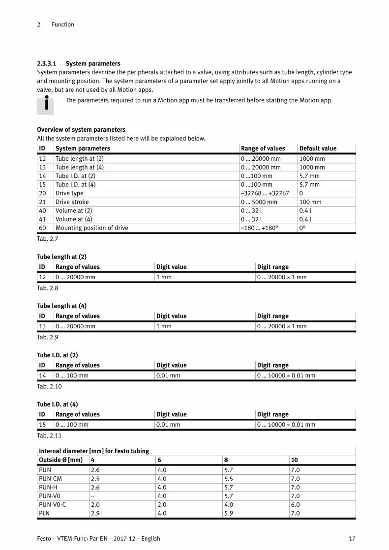
2.3.3.1 System parameters
System parameters describe the peripherals attached to a valve, using attributes such as tube length, cylinder type
and mounting position. The system parameters of a parameter set apply jointly to all Motion apps running on a
valve, but are not used by all Motion apps.
The parameters required to run a Motion app must be transferred before starting the Motion app.
Overview of system parameters
All the system parameters listed here will be explained below.
ID System parameters Range of values Default value
12 Tube length at (2) 0 … 20000 mm 1000 mm
13 Tube length at (4) 0 … 20000 mm 1000 mm
14 Tube I.D. at (2) 0 …100 mm 5.7 mm
15 Tube I.D. at (4) 0 …100 mm 5.7 mm
20 Drive type –32768 … +32767 0
21 Drive stroke 0 … 5000 mm 100 mm
40 Volume at (2) 0 … 32 l 0.4 l
41 Volume at (4) 0 … 32 l 0.4 l
60 Mounting position of drive –180 … +180° 0°
Tab. 2.7
Tube length at (2)
ID Range of values Digit value Digit range
12 0 … 20000 mm 1 mm 0 … 20000 × 1 mm
Tab. 2.8
Tube length at (4)
ID Range of values Digit value Digit range
13 0 … 20000 mm 1 mm 0 … 20000 × 1 mm
Tab. 2.9
Tube I.D. at (2)
ID Range of values Digit value Digit range
14 0 … 100 mm 0.01 mm 0 … 10000 × 0.01 mm
Tab. 2.10
Tube I.D. at (4)
ID Range of values Digit value Digit range
15 0 … 100 mm 0.01 mm 0 … 10000 × 0.01 mm
Tab. 2.11
Internal diameter [mm] for Festo tubing
Outside Ø [mm] 4 6 8 10
PUN 2.6 4.0 5.7 7.0
PUN-CM 2.5 4.0 5.5 7.0
PUN-H 2.6 4.0 5.7 7.0
PUN-V0 – 4.0 5.7 7.0
PUN-V0-C 2.0 2.0 4.0 6.0
PLN 2.9 4.0 5.9 7.0

2 Function
18 Festo – VTEM-Func+Par-EN – 2017-12 – English
Internal diameter [mm] for Festo tubing
Outside Ø [mm] 10864
PEN 2.7 4.0 5.7 7.0
PAN 2.9 4.0 5.9 7.0
PAN-MF 2.5 4.0 6.0 7.5
PAN-R 2.5 3.8 5.0 6.2
PFAN 2.9 4.0 5.9 7.0
Tab. 2.12
Drive type
The Festo drives supported by the Motion Terminal are shown in a list. The list contains a value for the “drive type”
parameter for each drive. The default value must be replaced with the value for one of the listed drive types before
using a corresponding Motion app.
ID Range of values
20 � C Supported peripherals
Tab. 2.13
Drive stroke
The drive stroke describes the maximum stroke of the drive without taking into consideration mechanical stops
within the total stroke.
ID Range of values Digit value Digit range
211) 0 … 5000 mm 1 mm 0 … 5000 × 1 mm
0 … 270° 1° 0 … 270°
1) When selecting a semi-rotary drive as drive type, the “drive stroke” parameter does not need to be defined. The value for the swivel angle is
determined from the order code for the semi-rotary drive and is automatically transferred to the “degrees” unit in the “drive stroke” parameter.
Tab. 2.14
Volume at (2)
ID Range of values Digit value Digit range
40 0 … 32 l 0.001 l 0 … 32000 × 0.001 l
Tab. 2.15
Volume at (4)
ID Range of values Digit value Digit range
41 0 … 32 l 0.001 l 0 … 32000 × 0.001 l
Tab. 2.16
Mounting position of drive
ID Range of values Digit value Digit range
60 –180 … +180° 0.01° –18000 … 18000 × 0.01°
Tab. 2.17
A positive value means that the mass is moved when advancing upward (away from
the ground) (port (4) pressurised, port (2) exhausted, switching position 14).
±180° 0°
+90°
–90°

2 Function
Festo – VTEM-Func+Par-EN – 2017-12 – English 19
The value given for the mounting position relates to the position of the plane on which the mass is moved, and
therefore changes as a function of the drive selected (� System parameter 20 “drive type”).
Drive system -135° -45° 0° 45° 135°
Cylinder with piston rod
Linear drive
(12 = ‘retracting’)
(14 = ‘advancing’) 12
14
12
14
12 14
12
14
12
14
Semi-rotary drive Semi-rotary drives may only be used in the following mounting situations where the
gravitational force resulting from the mounting position does not affect the movement
behaviour of the semi-rotary drive.
– Centre of gravity in the axis of rotation:
Any installation position is permitted.
– Centre of gravity outside the axis of rotation (not recommended):
Only vertical mounting position permitted; axis points vertically upward or
downward.
In these cases, there is no need to parameterise the “mounting position of drive”
parameter.
Use outside of the above-described mounting situations can lead to unpredictable
movement behaviour of the semi-rotary drive and is therefore not permitted.
Tab. 2.18
2.3.3.2 Application parameters
Application parameters describe the basic conditions under which a Motion app is to be executed, using attributes
such as mass during retracting and advancing, travel time, and acceleration. Here, the application parameters of
a�parameter set (� 2.3.3.4 Parameter sets) can be individually adapted for each Motion app. This means that the
“mass during retracting” can be defined differently for different Motion apps on the same valve.
Not all Motion apps use application parameters.
The parameters required to run a Motion app must be transferred before starting the Motion app.
Overview of application parameters
ID Application parameters
100 Retracting load1)
101 Advancing load2)
120 Travel time, retracting1)
121 Travel time, advancing2)
182 Max. pressure rise at (2)
183 Max. pressure rise at (4)
200 Max. leakage for status “good”
201 Max. leakage for status “warning”
202 Max. leakage for status “critical”
220 Characteristic (2)
221 Characteristic (4)
222 Pressure build-up function
1) (2) pressurised, (4) exhausted; switching position 12
2) (4) pressurised, (2) exhausted; switching position 14

2 Function
20 Festo – VTEM-Func+Par-EN – 2017-12 – English
ID Application parameters
255 Motion app to be taught in
1) (2) pressurised, (4) exhausted; switching position 12
2) (4) pressurised, (2) exhausted; switching position 14
Tab. 2.19
Retracting load ((2) pressurised)
ID Range of values Digit value Digit range
100 0 … 100 kg 0.01 kg 0 … 10000 × 0.01 kg
Tab. 2.20
Advancing load ((4) pressurised)
ID Range of values Digit value Digit range
101 0 … 100 kg 0.01 kg 0 … 10000 × 0.01 kg
Tab. 2.21
Travel time, retracting ((2) pressurised)
ID Range of values Digit value Digit range
120 0 … 300 s 0.01 s 0 … 30000 × 0.01 s
Tab. 2.22
Travel time, advancing ((4) pressurised)
ID Range of values Digit value Digit range
121 0 … 300 s 0.01 s 0 … 30000 × 0.01 s
Tab. 2.23
Max. pressure rise at (2)
ID Range of values Digit value Digit range
182 0.1 … 200 bar/s 0.01 bar/s 10 … 20000 × 0.01 bar/s
Tab. 2.24
Max. pressure rise at (4)
ID Range of values Digit value Digit range
183 0.1 … 200 bar/s 0.01 bar/s 10 … 20000 × 0.01 bar/s
Tab. 2.25
Max. leakage for status “good”
ID Range of values Digit value Digit range
200 2 … 600 l/h 0.1 l/h 20 … 6000 × 0.1 l/h
Tab. 2.26
Max. leakage for status “warning”
The actual range of values for this parameter depends on the “adjacent” parameters (200 and 202) and
must be between the values for these parameters.

2 Function
Festo – VTEM-Func+Par-EN – 2017-12 – English 21
ID Range of values Digit value Digit range
201 2 … 600 l/h 0.1 l/h 20 … 6000 × 0.1 l/h
Tab. 2.27
Max. leakage for status “critical”
ID Range of values Digit value Digit range
202 2 … 600 l/h 0.1 l/h 20 … 6000 × 0.1 l/h
Tab. 2.28
Characteristic (2)
ID Range of values Digit value Digit range
220 0 … 31) 1 0 … 31)
1) Significance is specific to the Motion app
Tab. 2.29
Characteristic (4)
ID Range of values Digit value Digit range
221 0 … 31) 1 0 … 31)
1) Significance is specific to the Motion app
Tab. 2.30
Pressure build-up function
When moving a pneumatic drive towards a chamber which is only supplied with low pressure (e.g. ambient
pressure), the movement of the drive may be unexpectedly fast.
The pressure build-up function prevents this behaviour by checking the pressure in the corresponding chamber. If
the pressure is too low, the chamber is actively pressurised before executing a travel command. The execution of the
travel command can therefore be delayed as a function of the connected peripherals and the prevailing pressure
conditions.
Owing to the pressure build-up in the chamber that is to be exhausted according to the travel command,
there may be a brief movement of the drive in the direction opposite to the travel command.
For applications in which this behaviour is undesirable, the pressure build-up function can be
deactivated.
ID Status of function Value of parameter
221 Active 1
Inactive 0
Tab. 2.31
Motion app to be taught in
The ID of the Motion app for which the teach-in data and reference value are to be determined during execution of
the teach-in run must be entered as a value in this parameter.
ID Range of values Digit value Digit range
255 1 … 59 1 1 … 59
Tab. 2.32

2 Function
22 Festo – VTEM-Func+Par-EN – 2017-12 – English
2.3.3.3 Teach-in data
Some Motion apps require a teach-in process to determine the characteristics of the connected peripherals and to
achieve the desired result during movement (� 2.6 Teach-in run). The data from this teach-in process are stored in
the parameter set in a manner specific to the Motion app (� 2.3.3.4 Parameter sets).
These data are continuously updated when the corresponding Motion app is in operation.
The teach-in data are stored in the parameter set that is currently active.
2.3.3.4 Parameter sets
The Motion Terminal can manage 5 different parameter sets for each valve, each set comprising system parameters,
application parameters and teach-in data (� 2.6 Teach-in run). When changing over the connected peripherals, it is
easy to modify the parameterisation of the valve by activating a different parameter set.
Parameter set 1 is automatically selected when the Motion Terminal is started. Changing the parameter
set is described in section � 3.4 Changing parameter set.
Structure of a parameter set
The following example is intended to illustrate the structure of a parameter set.
Valve on slot 1 Valve on slot 2
Parameter set 1 Parameter set 2 Parameter set 3 Parameter set 4 Parameter set 5 Parameter set 1 …
Parameter set 3 Motion App #01 Motion App #02 Motion App #03 Motion App #04 Motion App #…
System
parameters
Sys. par. a
Sys. par. b
Sys. par. c
Sys. par. …
Application
parameters
App. par. x App. par. x App. par. x App. par. x App. par. x
App. par. y App. par. y App. par. y App. par. y App. par. y
App. par. z App. par. z App. par. z App. par. z App. par. z
App. par. … App. par. … App. par. … App. par. … App. par. …
Teach-in data Data record 1 Data record 2 Data record 3 Data record 4 Data record 5
Tab. 2.33
2.3.4 Setpoint and actual values
Setpoint and actual values can be written and read cyclically by the process data.
Writing setpoint values: Output data (PDO, process data output)
Reading actual values: Input data (PDI, process data input)
The setpoint and actual values are specific to the individual Motion apps. The structure of the process data is
described in section � 2.4 Communication between PLC and Motion Terminal.
2.3.5 Waiting time between Motion apps
In the following cases, calibration of the associated valve takes place before the Motion app that has been started is
executed:
– Following a restart of the Motion Terminal, a Motion app is started for the first time.
– After execution of Motion App #01, a different Motion app is started for the first time.
This calibration can take up to 20 seconds and will be performed automatically prior to execution of the Motion app.

2 Function
Festo – VTEM-Func+Par-EN – 2017-12 – English 23
2.4 Communication between PLC and Motion Terminal
The communication between the higher-order controller (PLC) and the Motion Terminal controller is based on input
and output data of in each case 8 × 6 bytes from the CPX terminal. Each of the maximum 8 valves on a Motion
Terminal is assigned 6 bytes of input data (PDI) and 6 bytes of output data (PDO), regardless of the actual number of
valves present.
Valve on
slot 0
Valve on
slot 1
Valve on
slot 2
Valve on
slot 3
Valve on
slot 4
Valve on
slot 5
Valve on
slot 6
Valve on
slot 7
6 bytes PDI 6 bytes PDI 6 bytes PDI 6 bytes PDI 6 bytes PDI 6 bytes PDI 6 bytes PDI 6 bytes PDI
6 bytes PDO 6 bytes PDO 6 bytes PDO 6 bytes PDO 6 bytes PDO 6 bytes PDO 6 bytes PDO 6 bytes PDO
Depending on the current operating mode of a valve (� 2.4.2.1 Structure of the output data (PDO)), the following
functions and content can be transferred using the process data:
– Starting/running/ending a Motion app (� 2.4.2 Structure of the process data when running a Motion app)
– Parameterisation of the Motion app using the PLC (parameter download
� 3.1 Setting system and application parameters)
– Reading the configured Motion app (parameter upload) (�3.2 Reading out system and application parameters)
– Diagnostic information and acknowledging errors (� 2.7.3.6 Acknowledging errors)
2.4.1 Numerical representation
Setpoint values and actual values, as well as system and application parameters, are represented within
the process data as a two's complement value in the format “16 bit signed integer”.
2.4.2 Structure of the process data when running a Motion app
The use of process data when running a Motion app is described in section � 2.4.3.

2 Function
24 Festo – VTEM-Func+Par-EN – 2017-12 – English
2.4.2.1 Structure of the output data (PDO)
When a Motion app is running, the 6 bytes of output data (PDO) for each valve slot are divided into 3 sections:
– Command
– Setpoint value 1
– Setpoint value 2
Valve on slot 0 Valve on slot 1ÍÍÍÍ
Valve on slot 7
Byte 5 Byte 4 Byte 3 Byte 2 Byte 1 Byte 0 Byte 5 Byte 4 Byte 3ÍÍÍÍ
Byte 2 Byte 1 Byte 0
Setpoint value 2 Setpoint value 1 Command Setpoint value 2 Set
point
ÍÍÍÍÍÍ
Value 1 Command
“Command” section
PDO byte 1 PDO byte 0
Command
Bit 7 Bit 6 Bit 5 Bit 4 Bit 3 Bit 2 Bit 1 Bit 0 Bit 7 Bit 6 Bit 5 Bit 4 Bit 3 Bit 2 Bit 1 Bit 0
app option app control valve mode
Valve mode
The valve mode is specified by bits 5 ... 0 in byte 0 (PDO).
PDO byte 0
Bit 7 Bit 6 Bit 5 Bit 4 Bit 3 Bit 2 Bit 1 Bit 0
This section is allocated the same function in every operating mode and is of central importance for the
control of the Motion Terminal. Allocation of the other sections depends on the current operating mode of
the valve.
Value dec. Valve mode Description
0 Reserved Invalid value
1 … 59 Run Motion app
(value corresponds to Motion app ID)
Selection of the Motion app to be run, by means of
its ID. The setpoint values required to run the
Motion app are transferred using bytes 5 ... 2 (PDO).
60 Teach-in run Teaching in of the relevant characteristics of the
connected system for execution of particular Motion
apps.
61 End Motion app Ending the Motion app currently running on the
valve.
62 Acknowledge error Error must be acknowledged to change the valve
status from “not ready” to “configurable”.
63 Transfer mode Transfer of parameters, diagnostic information and
settings for the valves (� 2.4.4 Transfer mode).
Tab. 2.34
Control of the Motion app (app control)
The information for controlling the Motion app is specified using bits 7 ... 6 in byte 0 (PDO).
PDO byte 0
Bit 7 Bit 6 Bit 5 Bit 4 Bit 3 Bit 2 Bit 1 Bit 0
The exact function is specific to the Motion app and can be found in the description of the Motion app.

2 Function
Festo – VTEM-Func+Par-EN – 2017-12 – English 25
Setting the Motion app (app option)
The setting for a Motion app is specified using byte 1 (PDO).
PDO byte 1
The exact function is specific to the Motion app and can be found in the description of the Motion app.
“Setpoint value 1” and “setpoint value 2” sections
Setpoint values for executing a Motion app are specified using bytes 5 ... 4 (PDO) (setpoint 2) and 3 ... 2 (PDO)
(setpoint 1).
PDO byte 5 PDO byte 4 PDO byte 3 PDO byte 2
Setpoint value 2 Setpoint value 1
The exact function is specific to the Motion app and can be found in the description of the Motion app.
2.4.2.2 Structure of the input data (PDI)
Valve on slot 0 Valve on slot 1ÍÍÍÍ
Valve on slot 7
Byte 5 Byte 4 Byte 3 Byte 2 Byte 1 Byte 0 Byte 5 Byte 4 Byte 3ÍÍÍÍ
Byte 2 Byte 1 Byte 0
Actual value 2 Actual value 1 Status Actual value 2 ActualÍÍÍÍ
Value 1 Status
“State” section
PDI byte 1 PDI byte 0
Status
Bit 7 Bit 6 Bit 5 Bit 4 Bit 3 Bit 2 Bit 1 Bit 0 Bit 7 Bit 6 Bit 5 Bit 4 Bit 3 Bit 2 Bit 1 Bit 0
app state valve state valve mode
Valve mode
The valve mode that is currently active is fed back using bits 5 ... 0 in byte 0 (PDI).
PDI byte 0
Bit 7 Bit 6 Bit 5 Bit 4 Bit 3 Bit 2 Bit 1 Bit 0
Value dec. Valve mode Description
1 … 59 Motion app being run Display of currently running Motion app using the ID.
60 Teach-in run
61 Valve inactive (in normal position) No Motion app is currently being executed, or the
most recently executed Motion app has been
stopped.
62 Reserved Not used. Feedback for command “62”
(end Motion app) is “61” (valve inactive).
63 Transfer mode active Parameters can be transferred
(� 2.4.4 Transfer mode)
Tab. 2.35
Example
To start Motion App #05, the value “5” is transferred in the PDO section “valve mode”.
The Motion app is only actually started when the value “5” is present in the PDI section “valve mode” (and “2” is
present in the “valve state” section).

2 Function
26 Festo – VTEM-Func+Par-EN – 2017-12 – English
Valve state
The current state of the valve is given by bits 7 ... 6 in byte 0 (PDI).
PDI byte 0
Bit 7 Bit 6 Bit 5 Bit 4 Bit 3 Bit 2 Bit 1 Bit 0
Valve state Significance Bit 7 Bit 6 Dec.
Not ready Start process for Motion Terminal is not completed or an
error that has been detected and eliminated is yet to be
acknowledged.
0 0 0
Configurable A Motion app can be run or a switch to transfer mode can be
made.
0 1 1
Running A Motion app is currently being executed. 1 0 2
Failure An error has been detected but not yet eliminated.
The�Motion app has been stopped.
1 1 3
Tab. 2.36
App state
The current state of the app is given by a range of information using bits 7 ... 0 in byte 1 (PDI).
PDI byte 1
Bit 7 Bit 6 Bit 5 Bit 4 Bit 3 Bit 2 Bit 1 Bit 0
The information described here is valid when running all Motion apps.
Additional information specific to the Motion app, which is transferred in the app state, is given in the
description for the Motion app in question.
Indicating warnings
The presence of warnings in the diagnostic memory of the Motion Terminal is indicated using bit 7 in byte 1 (PDI).
PDI byte 1
Bit 7 Bit 6 Bit 5 Bit 4 Bit 3 Bit 2 Bit 1 Bit 0
Value Description
0 No warning present.
1 The active Motion app is reporting a warning that is present in the diagnostic memory of the Motion
Terminal.
Tab. 2.37
For how to deal with warnings and errors � 2.7 Diagnostics options.
2.4.3 Running a Motion app
Depending on the Motion app to be run, the system and application parameters must be defined before
operation (� 2.3.3 System and application parameters). The system and/or application parameters used
by a Motion app are documented in the description for the Motion app in question.
2.4.3.1 Prerequisites
– The Motion Terminal boot procedure is completed.
– System and application parameters required by the Motion app have been transferred
(� 3.1 Setting system and application parameters).
– If necessary, a teach-in run for the Motion app has been carried out (� 2.6 Teach-in run).

2 Function
Festo – VTEM-Func+Par-EN – 2017-12 – English 27
– The state of the valve on which the Motion app is to be run is “configurable”
(� 2.4.2.2 Structure of the input data (PDI)).
– There is no active error on the valve on which the Motion app is to be run
(� 2.7.3.5 Readout of the diagnostic memory, � 2.7.3.6 Acknowledging errors).
2.4.3.2 Starting a Motion app
To start a Motion app, setpoint values 1 and 2 and the command (comprising “valve mode”, “app control” and
“app�option”) must be transferred in the 6 byte PDO for the corresponding valve.
Example
Motion App #02 “Proportional directional control valve” (PDO byte 0 bits 5 ... 0 => 210) is to be started with the
following specifications:
– Switching status of the working ports (app control):
(2) active, (4) active (PDO byte 0 bit 7 => 1, PDO byte 0 bit 6 => 1)
– Valve type (app option): 2 x 3/3 (PDO byte 1 => 1510)
– Valve position (setpoint value 1): +50 % (PDO byte 2+3 => 500010)
PDO byte 5 4 3 2 1 0
Area setpoint
value 2
setpoint
value 1
command
Bits 15 … 0 15 … 0 7 6 5 4 3 2 1 0 7 6 5 4 3 2 1 0
Function setpoint
value 2
setpoint
value 1
app option app
control
valve mode
Value 4000 5000 0 0 0 0 1 1 1 0 1 1 0 0 0 0 1 0
The input data are used to feed back the current state of the valve and of the Motion app:
– Valve mode: Motion App #02 (PDI byte 0 bits 5 … 0 => 0000102)
– Valve state: running (PDI byte 0 bits 7 … 6 => 102)
– App state:
– Status information of Motion app: not used (PDI byte 1 bits 6 ... 0 => 000000)
– End-position sensing:
Sensor for end position ‘advanced’ gives “1” (PDI byte 1 bit 2 => 1)
Sensor for end position ‘retracted’ gives “0” (PDI byte 1 bit 0 => 0)
– Warning: no warning present (PDI byte 1 bit 7 => 0)
– Actual value 1: valve position: e.g. +50.02 % (PDI byte 3 … 2 => 500210)
– Actual value 2: valve position: e.g. +39.99% (PDI byte 5 … 4 => 399910)
PDI byte 5 4 3 2 1 0
Area actual
value 2
actual
value 1
status
Bits 15 … 0 15 … 0 7 6 5 4 3 2 1 0 7 6 5 4 3 2 1 0
Function actual
value 2
actual
value 1
app state valve
state
valve mode
Value 3999 5002 0 0 0 0 0 1 0 0 1 0 0 0 0 0 1 0
2.4.3.3 Controlling a Motion app
During operation, the behaviour of a Motion app can be controlled by adjusting the values for “app control”,
“app�option”, “setpoint value 1” and “setpoint value 2”.
2.4.3.4 Ending a Motion app
To end a Motion app, the valve mode must be set to “61”. The Motion app is then ended. The value in the
“valve�state” section of the input data (PDI) changes to “1” (configurable).
Another Motion app can now be started, or a switch to transfer mode can be made (� 2.4.4 Transfer mode).

2 Function
28 Festo – VTEM-Func+Par-EN – 2017-12 – English
2.4.3.5 Feedback in the case of incorrect output data
If incorrect output data is transferred from the higher-order controller to the Motion Terminal controller during
operation of a Motion app, the Motion app currently running is stopped and corresponding feedback is sent using
the input data:
– Valve mode: 61 (Motion app stopped) (PDI byte 0 bits 5 … 0 => 1111012)
– Valve state: configurable (PDI byte 0 bits 7 … 6 => 012)
– App state: � Tab. 2.38
– Actual value 1: (PDI byte 3 … 2 => current pressure [mbar] at port (2))
– Actual value 2: (PDI byte 5 … 4 => current pressure [mbar] at port (4))
PDI byte 5 4 3 2 1 0
Area actual
value 2
actual
value 1
status
Bits 15 … 0 15 … 0 7 6 5 4 3 2 1 0 7 6 5 4 3 2 1 0
Function actual
value 2
actual
value 1
app state valve
state
valve mode
Value current
pressure
current
pressure
� Tab. 2.38 0 1 1 1 1 1 0 1
PDI byte 1
Value dec. app state Significance
1 valve mode invalid Invalid value in “valve mode” section
2 app control invalid Invalid value in “app control” section
3 app option invalid Invalid value in “app option” section
4 setpoint1 invalid Invalid value in “setpoint value 1” section
5 setpoint2 invalid Invalid value in “setpoint value 2” section
6 parameters invalid Incorrect parameterisation1)
10 access denied (WebConfig access) Access by PLC denied owing to active access by WebConfig
interface.
11 blocked due to saving Access blocked due to active save process.
12 no licence for this app No licence available for the requested Motion app.
13 all licences in use No free licence available for the requested Motion app.
14 licence file invalid Licence file is invalid.
15 no valve detected No valve detected on the valve position addressed.
16 valve self calibration running Valve self-calibration process in operation.
1) More precise information can be determined using the diagnostics channel in the transfer mode
(� 2.7.3 Diagnostics channel in transfer mode, � Appendix D Diagnostics using transfer mode, error codes 71 ... 74)
Tab. 2.38
2.4.4 Transfer mode
The transfer mode (valve mode = “63”) gives the option of exchanging information such as parameters or diagnostic
information between the Motion Terminal and the higher-order controller using a range of channels. The transfer
mode makes use of process data (6 bytes output data (PDO) and 6 bytes input data (PDI) for each valve).

2 Function
Festo – VTEM-Func+Par-EN – 2017-12 – English 29
2.4.4.1 Structure of the process data in transfer mode
Structure of the output data (PDO)
When using transfer mode, the 6 bytes of output data (PDO) for each valve slot are divided into 3 sections:
– Command
– Parameter
– Value
Valve on slot 0 Valve on slot 1ÍÍÍÍ
Valve on slot 7
Byte 5 Byte 4 Byte 3 Byte 2 Byte 1 Byte 0 Byte 5 Byte 4 Byte 3ÍÍÍÍ
Byte 2 Byte 1 Byte 0
Value Parameter Command Value ParaÍÍÍÍ
meter Command
“Command” section
PDO byte 1 PDO byte 0
Command
Bit 7 Bit 6 Bit 5 Bit 4 Bit 3 Bit 2 Bit 1 Bit 0 Bit 7 Bit 6 Bit 5 Bit 4 Bit 3 Bit 2 Bit 1 Bit 0
transfer control channel – valve mode = 63
Byte 0
The valve is set to transfer mode using the valve mode (PDO byte 0 bits 5 ... 0) with value “63”.
PDO byte 0
Bit 7 Bit 6 Bit 5 Bit 4 Bit 3 Bit 2 Bit 1 Bit 0
Bits 7 ... 6 on byte 0 (PDO) are ignored in transfer mode.
Channel
Bits 4 ... 0 in byte 1 (PDO) are used to select the channel on which information is to be transferred.
PDO byte 1
Bit 7 Bit 6 Bit 5 Bit 4 Bit 3 Bit 2 Bit 1 Bit 0
Value
dec.1)
Channel Significance
1 parameter set 12) Parameterisation in parameter set 1
2 parameter set 22) Parameterisation in parameter set 2
3 parameter set 32) Parameterisation in parameter set 3
4 parameter set 42) Parameterisation in parameter set 4
5 parameter set 52) Parameterisation in parameter set 5
15 valve setting Valve settings
25 Information3) Information on the status of the terminal
31 malfunctions3) Access to the diagnostic memory
1) Values that are not listed are reserved and cannot be used.
2) � 2.3.3.4 Parameter sets
3) � Tab. 2.41
Tab. 2.39
Transfer control
Transfer in transfer mode is controlled using bits 7 ... 5 in byte 1 (PDO).
PDO byte 1
Bit 7 Bit 6 Bit 5 Bit 4 Bit 3 Bit 2 Bit 1 Bit 0

2 Function
30 Festo – VTEM-Func+Par-EN – 2017-12 – English
Value dec.1) Transmitting Significance
1 Download Transfer from the PLC to the Motion Terminal
2 Upload Transfer from the Motion Terminal to the PLC
3 End transfer mode Transfer mode is exited; the valve mode switches to
61 (valve in normal position), the valve state to 1
(configurable).
4 Save parameterisation as persistent data The data for the valve currently being parameterised
are saved to the Motion Terminal as persistent data.
1) Values that are not listed are reserved and cannot be used.
Tab. 2.40
Valve on slot 0 Valve on slot 1ÍÍÍÍ
Valve on slot 7
Byte 5 Byte 4 Byte 3 Byte 2 Byte 1 Byte 0 Byte 5 Byte 4 Byte 3ÍÍÍÍ
Byte 2 Byte 1 Byte 0
Value Parameter Command Value ParaÍÍÍÍmeter Command
“Parameter” section
PDO byte 3 PDO byte 2
Parameter
Bit 7 Bit 6 Bit 5 Bit 4 Bit 3 Bit 2 Bit 1 Bit 0 Bit 7 Bit 6 Bit 5 Bit 4 Bit 3 Bit 2 Bit 1 Bit 0
index addressed Motion app
Addressed Motion app
When writing or reading application parameters, the ID of the addressed Motion app is entered in byte 2 (PDO).
PDO byte 2
For settings that are not specific to the Motion app (e.g. system parameters, or the selection of the active
parameter set), a “0” is entered here.
Index
Depending on the channel selected, the information to be transferred is more precisely identified by means of byte 3
(PDO).
PDO byte 3
Channel Index Significance Digit value
1 … 5 0 … 255 ID of the system or application parameter that is to be transferred 1
15 1 The entry in the “value” section corresponds to the number of the active
parameter set
1
1) The valve on which the transfer mode will be executed
2) For commissioning with the reference value determined in the teach-in run for Motion App #12 “Leakage diagnostics”

2 Function
Festo – VTEM-Func+Par-EN – 2017-12 – English 31
Channel Digit valueSignificanceIndex
25 1 Ambient pressure 0.001 bar abs.
2 Supply pressure (absolute) 0.001 bar abs.
3 Supply pressure (relative) 0.001 bar rel.
4 Exhaust air pressure (absolute) 0.001 bar abs.
5 Exhaust air pressure (relative) 0.001 bar rel.
10 Temperature at atmospheric pressure sensor 0.1 °C
11 Temperature at supply pressure sensor 0.1 °C
12 Temperature at exhaust air pressure sensor 0.1 °C
13 Temperature at valve1), working port (2) 0.1 °C
14 Temperature at valve1), working port (4) 0.1 °C
100 Leakage reference value2) for working port (2), parameter set 1 0.1 l/h
101 Leakage reference value2) for working port (4), parameter set 1 0.1 l/h
102 Leakage reference value2) for working port (2), parameter set 2 0.1 l/h
103 Leakage reference value2) for working port (4), parameter set 2 0.1 l/h
104 Leakage reference value2) for working port (2), parameter set 3 0.1 l/h
105 Leakage reference value2) for working port (4), parameter set 3 0.1 l/h
106 Leakage reference value2) for working port (2), parameter set 4 0.1 l/h
107 Leakage reference value2) for working port (4), parameter set 4 0.1 l/h
108 Leakage reference value2) for working port (2), parameter set 5 0.1 l/h
109 Leakage reference value2) for working port (4), parameter set 5 0.1 l/h
31 1 … 40 Number of position in diagnostic memory of content to be read 1
253 Position of the most recent diagnostic message of type “error” 1
254 Position of the earliest diagnostic message of type “error” 1
255 Number of diagnostic messages in the diagnostic memory 1
1) The valve on which the transfer mode will be executed
2) For commissioning with the reference value determined in the teach-in run for Motion App #12 “Leakage diagnostics”
Tab. 2.41
“Value” section
PDO byte 5 PDO byte 4
Value
This section is used to transfer numerical values. The significance and function of the numerical values are defined
by the sections described above.

2 Function
32 Festo – VTEM-Func+Par-EN – 2017-12 – English
Structure of the input data (PDI)
In transfer mode, the input data (PDI) serve to confirm the transfer that has taken place. To do this, the information
as to “valve mode”, “channel”, “transfer control”, “addressed app” and “index” that has been transferred to the
output data is fed back at the corresponding positions in the input data.
The “valve state” section gives the information described in section � 2.4.2.2.
Valve on slot 0 Valve on slot 1ÍÍÍÍ
Valve on slot 7
Byte 5 Byte 4 Byte 3 Byte 2 Byte 1 Byte 0 Byte 5 Byte 4 Byte 3ÍÍÍÍ
Byte 2 Byte 1 Byte 0
Value Parameter Status Value ParaÍÍÍÍ
meter Status
“Command” section
PDI byte 1 PDI byte 0
Command
Bit 7 Bit 6 Bit 5 Bit 4 Bit 3 Bit 2 Bit 1 Bit 0 Bit 7 Bit 6 Bit 5 Bit 4 Bit 3 Bit 2 Bit 1 Bit 0
transfer control channel valve state valve mode = 63
Valve on slot 0 Valve on slot 1ÍÍÍÍ
Valve on slot 7
Byte 5 Byte 4 Byte 3 Byte 2 Byte 1 Byte 0 Byte 5 Byte 4 Byte 3ÍÍÍÍ
Byte 2 Byte 1 Byte 0
Value Parameter Status Value ParaÍÍÍÍ
meter Status
“Parameter” section
PDI byte 3 PDI byte 2
Parameter
Bit 7 Bit 6 Bit 5 Bit 4 Bit 3 Bit 2 Bit 1 Bit 0 Bit 7 Bit 6 Bit 5 Bit 4 Bit 3 Bit 2 Bit 1 Bit 0
index addressed Motion app
2.4.4.2 Feedback in the case of incorrect output data
If invalid information is transmitted as part of the output data, corresponding feedback is provided in the input data
in transfer mode:
– Valve mode: 63 (transfer mode active) (PDI byte 0 bits 5 … 0 => 1111112)
– Valve state: gives the information described in section � 2.4.2.2.
– Channel: (PDI byte 1 bits 4 … 0 => 0)
– Transfer control: (PDI byte 1 bits 7 … 5 => 0)
– Addressed Motion app: (PDI byte 2 => 0)
– Index: (PDI byte 3 => 0)
– Value: (PDI byte 5 … 4 � Tab. 2.42)
Allocating invalid information
The “value” section indicates which part of the output data contains invalid information.
PDI byte 5 PDI byte 4
Value
Value invalid command Significance
1 invalid channel Invalid value in “channel” section
2 invalid transfer control Invalid value in “transfer control” section

2 Function
Festo – VTEM-Func+Par-EN – 2017-12 – English 33
Value Significanceinvalid command
3 invalid addressed app Invalid value in “addressed app” section
4 invalid index Invalid value in “index” section
5 Invalid value Invalid value in “value” section
6 invalid combination Invalid combination of values in various sections
Tab. 2.42
Example of input data with incorrect value in “index” section
PDI byte 1 PDI byte 0
Command
Bit 7 Bit 6 Bit 5 Bit 4 Bit 3 Bit 2 Bit 1 Bit 0 Bit 7 Bit 6 Bit 5 Bit 4 Bit 3 Bit 2 Bit 1 Bit 0
0 0 0 0 0 0 0 0 … … 1 1 1 1 1 1
transfer control = 0 channel = 0 valve state valve mode = 63 (transfer mode)
PDI byte 3 PDI byte 2
Parameter
Bit 7 Bit 6 Bit 5 Bit 4 Bit 3 Bit 2 Bit 1 Bit 0 Bit 7 Bit 6 Bit 5 Bit 4 Bit 3 Bit 2 Bit 1 Bit 0
0 0 0 0 0 0 0 0 0 0 0 0 0 0 0 0
index = 0 addressed Motion app = 0
PDI byte 5 PDI byte 4
Value
Bit 15 Bit 14 Bit 13 Bit 12 Bit 11 Bit 10 Bit 9 Bit 8 Bit 7 Bit 6 Bit 5 Bit 4 Bit 3 Bit 2 Bit 1 Bit 0
0 0 0 0 0 0 0 0 0 0 0 0 0 1 0 0
value = 4
2.4.4.3 Saving settings as persistent data
To save the current settings of a valve on the Motion Terminal as persistent data, the transfer control method
“save�persistent” (transfer control = 4) is used. No special channel is required for this; the value “channel” is not
evaluated.
After performing a teach-in run, the “save persistent” function should be executed to store the data
obtained during the teach-in run permanently on the Motion Terminal controller.
Otherwise, the teach-in run must be executed again after restarting the Motion Terminal
(� 2.6.7 Saving the teach-in data).
Status of save process
The status of the save process is shown in the “value” section of the input data (PDI).
PDI byte 5 PDI byte 4
Value
Value Saving progress Significance/remedy
1 saving in progress Save process active.
2 saving successful Save process is completed.
3 saving not possible Save process cannot be executed.
� Repeat the process.
� If the problem persists, contact Festo Support.
4 saving failed Save process failed.
� Repeat the process.
� If the problem persists, contact Festo Support.
Tab. 2.43

2 Function
34 Festo – VTEM-Func+Par-EN – 2017-12 – English
Content of output data for saving as persistent data
PDO byte 1 PDO byte 0
Command
Bit 7 Bit 6 Bit 5 Bit 4 Bit 3 Bit 2 Bit 1 Bit 0 Bit 7 Bit 6 Bit 5 Bit 4 Bit 3 Bit 2 Bit 1 Bit 0
1 0 0 … … … … … 0 0 1 1 1 1 1 1
transfer control = 4
(save persistent)
channel = …
(ignored)
– valve mode = 63 (transfer mode)
PDO byte 3 PDO byte 2
Parameter
Bit 7 Bit 6 Bit 5 Bit 4 Bit 3 Bit 2 Bit 1 Bit 0 Bit 7 Bit 6 Bit 5 Bit 4 Bit 3 Bit 2 Bit 1 Bit 0
0 0 0 0 0 0 0 0 0 0 0 0 0 0 0 0
index = 0 addressed Motion app = 0
PDO byte 5 PDO byte 4
Value
Bit 15 Bit 14 Bit 13 Bit 12 Bit 11 Bit 10 Bit 9 Bit 8 Bit 7 Bit 6 Bit 5 Bit 4 Bit 3 Bit 2 Bit 1 Bit 0
0 0 0 0 0 0 0 0 0 0 0 0 0 0 0 0
value = 0
Content of input data if save process is successful:
PDI byte 1 PDI byte 0
Command
Bit 7 Bit 6 Bit 5 Bit 4 Bit 3 Bit 2 Bit 1 Bit 0 Bit 7 Bit 6 Bit 5 Bit 4 Bit 3 Bit 2 Bit 1 Bit 0
1 0 0 … … … … … … … 1 1 1 1 1 1
transfer control = 4
(save persistent)
channel = … valve state valve mode = 63 (transfer mode)
PDI byte 3 PDI byte 2
Parameter
Bit 7 Bit 6 Bit 5 Bit 4 Bit 3 Bit 2 Bit 1 Bit 0 Bit 7 Bit 6 Bit 5 Bit 4 Bit 3 Bit 2 Bit 1 Bit 0
0 0 1 0 1 1 1 1 0 0 1 1 1 1 1 1
index = 0 addressed Motion app = 0
PDI byte 5 PDI byte 4
Value
Bit 15 Bit 14 Bit 13 Bit 12 Bit 11 Bit 10 Bit 9 Bit 8 Bit 7 Bit 6 Bit 5 Bit 4 Bit 3 Bit 2 Bit 1 Bit 0
0 0 0 0 0 0 0 0 0 0 0 0 0 0 1 0
value = 2 (saving successful)

2 Function
Festo – VTEM-Func+Par-EN – 2017-12 – English 35
2.5 Motion App #01: Directional control valve functions
Motion app ID Pictogram for Motion app
01
Tab. 2.44
The Motion app ID must be transferred using the “valve mode” section of the process data (bits 5 ... 0 in
byte 0 (PDO)) to run the Motion app on a valve (� 2.4.2.1 Structure of the output data (PDO)).
2.5.1 Functional description
The Motion app makes 9 directional control valve functions available for execution by the corresponding valve. The
directional control valve function makes it possible to assign the characteristics of a conventional switching valve to
a valve on the Motion Terminal. The integrated sensors enable monitoring of the switching position and of the
pressure at the working ports. If the pilot pressure or power supply are interrupted, the valve reverts to its
mechanical normal position (all channels are blocked).
The valve types listed in section � 2.5.5.1 can be allocated cyclically to the CPX terminal by means of the process
data. In addition, the switching status of the particular valve type can be specified cyclically using the process data
of the CPX terminal.
2.5.2 Sensors required
None
2.5.3 System parameters used
None
2.5.4 Application parameters used
None
2.5.5 Set values
The structure of the process data when running a Motion app is described in section � 2.4.2.
2.5.5.1 Setting the Motion app (app option)
Valve type
The valve type is defined using byte 1 (PDO).
PDO byte 1
Valve type Value dec.
4/2 mono 0
4/3 G (normally closed) (default setting) 1
4/3 B (normally open) 2
4/3 E (normally exhausted) 3
2 × 3/2 O (normally open) 4
2 × 3/2 G (normally closed) 5
3/2 O + 3/2 G 6
4/2 bistable 7
2 × 2/2 G (normally closed) 8
Tab. 2.45

2 Function
36 Festo – VTEM-Func+Par-EN – 2017-12 – English
2.5.5.2 Control of the Motion app (app control)
Switching status of the valve
The switching status at the working ports (2) and (4) of the valve is controlled using bits 7 ... 6 in byte 0 (PDO) and is
dependent on the valve type defined.
PDO byte 0
Bit 7 Bit 6 Bit 5 Bit 4 Bit 3 Bit 2 Bit 1 Bit 0
Possible switching statuses:
– Closed (G)
– Pressurised (B)
– Exhausted (E)
Conventional valve type Switching
status
Replacement
symbol1)
Byte 0 Dec.
(4) (2) Bit 7 Bit 6
4/2 mono E B – 2) 0 0
B E – 2) 1 1
4/3 G
(normal position: closed)
G G 0 0 0
E B 0 1 1
B E 1 0 2
G G 1 1 3
4/3 B
(normal position: pressurised)
B B 0 0 0
E B 0 1 1
B E 1 0 2
B B 1 1 3
1) The symbol in this column replaces the full bridge in the circuit diagram for the valve VEVM and therefore represents the function in the
switched state of the valve with corresponding setpoint value (right columns).
2) This bit is ignored

2 Function
Festo – VTEM-Func+Par-EN – 2017-12 – English 37
Conventional valve type Dec.Byte 0Replacement
symbol1)
Switching
status
Conventional valve type
Bit 6Bit 7(2)(4)
4/3 E
(normal position: exhausted)
E E 0 0 0
E B 0 1 1
B E 1 0 2
E E 1 1 3
2 × 3/2 O
(normal position: open)
B B 0 0 0
E B 0 1 1
B E 1 0 2
E E 1 1 3
2 × 3/2 G
(normal position: closed)
E E 0 0 0
B E 0 1 1
E B 1 0 2
B B 1 1 3
1) The symbol in this column replaces the full bridge in the circuit diagram for the valve VEVM and therefore represents the function in the
switched state of the valve with corresponding setpoint value (right columns).
2) This bit is ignored

2 Function
38 Festo – VTEM-Func+Par-EN – 2017-12 – English
Conventional valve type Dec.Byte 0Replacement
symbol1)
Switching
status
Conventional valve type
Bit 6Bit 7(2)(4)
3/2 O + 3/2 G
Normal position: retracting
((2) pressurised, (4) exhausted)
E B 0 0 0
B B 0 1 1
E E 1 0 2
B E 1 1 3
4/2 bistable
Initial position:
When the valve type is selected for
the�first time, (2) and (4) are blocked.
If a switch is made from a different
valve type to 4/2 bistable, the most
recent switching position remains
active.
Hold status 0 0 0
E B 0 1 1
B E 1 0 2
Hold status 1 1 3
2 × 2/2 G
Normal position: closed
G G 0 0 0
B G 0 1 1
G B 1 0 2
B B 1 1 3
1) The symbol in this column replaces the full bridge in the circuit diagram for the valve VEVM and therefore represents the function in the
switched state of the valve with corresponding setpoint value (right columns).
2) This bit is ignored
Tab. 2.46
2.5.5.3 Setpoint value 1 and setpoint value 2
The Motion app does not use any setpoint functions.
2.5.6 Feedback values
2.5.6.1 App state
Status of the digital inputs (end-position sensing)
The status of the inputs of the digital input module CTMM-...-D-... that are assigned to the valve currently in use
(� 2.1.1.5 Input module CTMM-S1-A/D-… (optional)) is shown using bits 2 and 0 in byte 1 (PDI).
Assigning the inputs to the valve slots is described in section � 2.1.1.5.

2 Function
Festo – VTEM-Func+Par-EN – 2017-12 – English 39
PDI byte 1
Bit 7 Bit 6 Bit 5 Bit 4 Bit 3 Bit 2 Bit 1 Bit 0
Position Bit 2 Bit 1 Bit 0
Status at input with odd number
(corresponds to position “‘advanced’ end position reached”1))
01
Status at input with even number
(corresponds to position “‘retracted’ end position reached”2))
01
1) (4) pressurised, (2) exhausted; switching position 14
2) (2) pressurised, (4) exhausted; switching position 12
Tab. 2.47
Switching position at the working ports (2) and (4)
The switching position at the working ports (2) and (4) of the valve is given by bits 6 ... 5 (4) and 4 ... 3 (2) in byte 1
(PDI).
PDI byte 1
Bit 7 Bit 6 Bit 5 Bit 4 Bit 3 Bit 2 Bit 1 Bit 0
Switching position Bit 6 Bit 5 Bit 4 Bit 3
(4) (2)
Closed 0 0
Pressurised 0 1
Exhausted 1 0
Error1) 1 1
Closed 0 0
Pressurised 0 1
Exhausted 1 0
Error1) 1 1
1) If the problem persists, contact Festo Support.
Tab. 2.48
Warning
The presence of warnings in the diagnostic memory of the Motion Terminal is indicated using bit 7 in byte 1 (PDI).
PDI byte 1
Bit 7 Bit 6 Bit 5 Bit 4 Bit 3 Bit 2 Bit 1 Bit 0
Value Description
0 No warning present.
1 Warning is present in the diagnostic memory of the Motion Terminal.
Tab. 2.49
For how to deal with warnings and errors � 2.7 Diagnostics options.

2 Function
40 Festo – VTEM-Func+Par-EN – 2017-12 – English
2.5.6.2 Actual value 1 and actual value 2
Measured pressure at working ports (2) and (4)
The measured pressure at the working ports (2) and (4) of the valve is given as a signed integer value by bytes
5 ... 4�(PDI) (4) and 3 ... 2 (PDI) (2).
PDI byte 5 PDI byte 4 PDI byte 3 PDI byte 2
(4) (2)
Connection Range of values Digit value Digit range Data type Byte (PDI)
(4) –1000 … +32767 mbar 1 mbar –1000 … +32767 × 1 mbar 16 bit signed integer 5 … 4
(2) –1000 … +32767 mbar 1 mbar –1000 … +32767 × 1 mbar 16 bit signed integer 3 … 2
Tab. 2.50

2 Function
Festo – VTEM-Func+Par-EN – 2017-12 – English 41
2.6 Teach-in run
Various motion apps require information about the physical behaviour of the connected peripherals in order to run.
This information is determined by the Motion Terminal during the process referred to as the “teach-in run”.
The�information is saved as “teach-in data” within a parameter set on the Motion Terminal controller
(� 2.3.3 System and application parameters).
A teach-in run can be executed in 2 different modes:
– Automatic
An automatic program is executed which determines and saves the corresponding teach-in data.
– Manual
The valve is in teach-in mode. The movements of the drive are controlled manually (via the WebConfig interface
or using the higher-order controller).
This allows individual movements to be executed which can each then be analysed by the teach-in routine.
The type of teach-in run that can be used depends on the Motion app for which the teach-in data are to
be determined. Not all Motion apps have the option of both types of teach-in run.
2.6.1 Prerequisites for starting the teach-in run
Before starting a teach-in run for a particular Motion app, the system and application parameters used by this
Motion app must have been parameterised.
In addition, the application parameter “Motion app to be taught in” (255) must be parameterised to the ID of the
Motion app for which the teach-in run is to be executed (� 3.1 Setting system and application parameters).
Application parameters can be defined individually for each Motion app on a valve
(� 2.3.3 System and application parameters).
To carry out the teach-in run, the application parameter “Motion app to be taught in” (255) must be
defined for the “teach-in run” mode (60). In this case, the teach-in run is treated like a Motion app.
The�ID�of the Motion app for which a teach-in run is to be executed must be assigned as a value to the
application parameter.
Example
A teach-in run for Motion App #07 “Travel time specification” is to be executed.
To do this, the value “7” must be assigned to the application parameter “Motion app to be taught in”
(255) for the “teach-in run” mode (60).
After defining the application parameter 255, you must exit transfer mode. The valve can now be switched to the
“teach-in run” mode (60).
2.6.2 Selection of the teach-in run mode
The teach-in run mode (automatic/manual) is specified using bits 7 ... 6 in byte 0 (PDO).
PDO byte 0
Bit 7 Bit 6 Bit 5 Bit 4 Bit 3 Bit 2 Bit 1 Bit 0
Teach-in run mode Bit 7 Bit 6 Dec.
Stop teach-in run 0 0 0
Execute automatic teach-in run 0 1 1
Execute manual teach-in run 1 0 2
Reserved 1 1 3
Tab. 2.51

2 Function
42 Festo – VTEM-Func+Par-EN – 2017-12 – English
2.6.3 Controlling the manual teach-in run
The movement of the drive for manual determination of the teach-in data is controlled using bytes 3 ... 2 (PDO).
PDO byte 3 PDO byte 2
Function Switching
status
Replacement
symbol1)
Value dec.
(4) (2)
Blocked G G 0
Advancing B E 1
Retracting E B 2
Exhausting E E 3
1) The symbol in this column replaces the full bridge in the circuit diagram for the valve VEVM and therefore represents the function in the
switched state of the valve with corresponding setpoint value (right column).
Tab. 2.52
2.6.4 End-position sensing
If the Motion app to be taught in requires sensors, the information as to whether the end positions have been
reached is provided by bits 2 and 0 in byte 1 (PDI).
Assigning the inputs to the valve slots is described in section � 2.1.1.5.
PDI byte 1
Bit 7 Bit 6 Bit 5 Bit 4 Bit 3 Bit 2 Bit 1 Bit 0
Position Bit 2 Bit 1 Bit 0
Status at input with odd number
(corresponds to position “‘advanced’ end position reached”1))
01
Status at input with even number
(corresponds to position “‘retracted’ end position reached”2))
01
1) (4) pressurised, (2) exhausted; switching position 14
2) (2) pressurised, (4) exhausted; switching position 12
Tab. 2.53

2 Function
Festo – VTEM-Func+Par-EN – 2017-12 – English 43
2.6.5 State of teach-in run
The current state of the teach-in run is given by bits 6 ... 3 in byte 1 (PDI).
PDI byte 1
Bit 7 Bit 6 Bit 5 Bit 4 Bit 3 Bit 2 Bit 1 Bit 0
Status Bit 6 Bit 5 Bit 4 Bit 3 Dec.
Reserved 0 0 0 0 0
No teach-in data present (unlearned) 0 0 0 1 1
Tubing connection being checked (check tubes) 0 0 1 0 2
Control algorithm being determined (choose control) 0 0 1 1 3
Movement parameters being adjusted (tune trajectory) 0 1 0 0 4
Reference value being determined (determine reference value) 0 1 0 1 5
Partially completed (only for (2)) 1 1 0 0 12
Partially completed (only for (4)) 1 1 0 1 13
Teach-in run completed (finished) 1 1 1 0 14
An error has occurred (error) 1 1 1 1 15
Tab. 2.54
2.6.6 Sequence of teach-in run
2.6.6.1 Automatic teach-in run
After the teach-in run mode (� 2.6.2) has been set to “Execute automatic teach-in run”, the teach-in run starts. In
this mode, the drive is moved from one end position to the other until the data required to execute the motion app
have been determined.
The teach-in run state then changes to “14” (finished) (� 2.6.5).
2.6.6.2 Manual teach-in run
After the teach-in run mode (� 2.6.2) has been set to “Execute manual teach-in run”, the drive can be moved
between the end positions using the control for the manual teach-in run (� 2.6.3). The process can be observed
using the “state of the teach-in run” (� 2.6.5).
The teach-in run is completed when the “state of the teach-in run” changes to “14” (finished) (� 2.6.5).
2.6.7 Saving the teach-in data
The teach-in data and reference values determined during the teach-in run are automatically saved in the active
parameter set on the Motion Terminal controller as persistent data.
While the Motion app is running, the teach-in data are continuously reviewed and adjusted if appropriate. These
adjustments are also saved directly as persistent data.
In the event of a change to the system and/or application parameters, the teach-in data and reference
values are discarded, as in this case it must be assumed that they no longer match the modified
configuration.
Therefore, following the change to the system and/or application parameters in a parameter set, a new
teach-in run must be executed for the Motion app affected by the changes.
The teach-in data and reference values are also reset if the system and application parameters, which
are�always the same, are transferred from the higher-order controller at system start but have never been
saved as persistent data on the Motion Terminal controller.
In this case, the Motion Terminal starts with the default values for the parameters. As soon as these are
overwritten by the higher-order controller, this change to the parameters causes the teach-in data and
reference values to be discarded.
To prevent this behaviour, the system and application parameters must be saved once as persistent data
on the Motion Terminal controller. This ensures that, when the higher-order controller transfers the
parameters, which are always the same, no change can be detected between the saved and transferred
values.

2 Function
44 Festo – VTEM-Func+Par-EN – 2017-12 – English
2.7 Diagnostics options
Various options are available for diagnosing malfunctions.
Diagnostics option Description Detailed information
LED display components The general system status of the Motion Terminal is
indicated by the LED display components on the
controller, on the valves and on the input modules.
� 2.7.1
CPX system diagnostics The CPX system diagnostics provides information on
the nature of malfunctions within the CPS terminal
(including the Motion Terminal) by way of CPX error
numbers.
� 2.7.2
� CPX system description
Diagnostics channel in
transfer mode
(Motion�Terminal)
In addition to the information from the CPX
diagnostics, the Motion Terminal provides
information on errors and warnings. This information
can be accessed via the diagnostics channel in
transfer mode.
� 2.7.3
Tab. 2.55
2.7.1 LED display components
2.7.1.1 Controller
LED indicator PL (power load, load voltage supply UVAL)
LED (green) Significance Action
Illuminated
ON
OFFVoltage is present. No error. –
Off
ON
OFFVoltage is not present. � Check connection of the power supply.
Tab. 2.56
LED indicator M (modify)
LED (yellow) Significance Action
Off
ON
OFFConfiguration inactive: no access via the
WebConfig interface.
–
Illuminated
ON
OFFConfiguration active: The WebConfig
interface has write access, or the PLC is
executing write access on the
parameterisation of the controller.
–
Tab. 2.57
LED indicator PS (power system, operating voltage supply UEL/SEN)
LED (green) Significance Action
Illuminated
ON
OFFVoltage is present. No error. –
Flashing
ON
OFFVoltage is present but outside the toler
ance range.
� Eliminate short circuit/overload.
Off
ON
OFFVoltage is not present. � Check connection of the power supply.
Tab. 2.58

2 Function
Festo – VTEM-Func+Par-EN – 2017-12 – English 45
LED indicator SF (system failure)
LED (red) Significance Action
Off
ON
OFFNo error –
Illuminated
ON
OFFVoltage of the load voltage supply UVAL is
outside the tolerance range.
� Eliminate short circuit/overload.
Access to WebConfig interface is not
possible or only conditionally.
� Switch operating voltage supply
UEL/SEN off and back on.
Tab. 2.59
LED indicator TP (Ethernet link/traffic)
LED (green) Significance Action
Illuminated
ON
OFFNetwork connection is OK (link). –
Flashing
ON
OFFData traffic (traffic)
Flashing frequency is dependent on the
traffic.
–
Off
ON
OFFNo network connection / network cable is
not connected.
If access to the WebConfig interface is
required:
� Check network connection.
Tab. 2.60
2.7.1.2 Valve
LED indicator valve state
LED (blue/red) Significance Action
Illuminated
red
ON
OFFValve error � Check error log (� 2.7.3)
Load voltage supply UVAL is not applied. � Check connection of the power supply
UVAL.
Illuminated
blue
ON
OFFError-free operation –
Flashing
blue
ON
OFFUpdate –
Valve booting. –
Valve being calibrated (� 2.3.5). –
Off
ON
OFFValve has no power supply. � If the power supply of the terminal is
switched on, check valve to ensure it is
seated properly.
Tab. 2.61
2.7.1.3 Analogue input module
LED indicator P
LED (red) Significance Action
Off
ON
OFFNo error –
Illuminated
ON
OFFShort circuit/overload in sensor supply. � Eliminate short circuit/overload.
Module error � Switch operating voltage supply
UEL/SEN off and back on.
Tab. 2.62

2 Function
46 Festo – VTEM-Func+Par-EN – 2017-12 – English
2.7.1.4 Digital input module
LED indicator P
LED (red) Significance Action
Off
ON
OFFNo error –
Illuminated
ON
OFFShort circuit/overload in sensor supply. � Eliminate short circuit/overload.
Tab. 2.63
LED indicator input status
LED (green) Significance Action
Illuminated
ON
OFFLogic 1
(Signal is present).
–
Off
ON
OFFLogic 0
(Signal is not present).
–
Tab. 2.64

2 Function
Festo – VTEM-Func+Par-EN – 2017-12 – English 47
2.7.2 Diagnostic interface
The diagnostic interface for the CPX terminal makes it possible to locate a malfunction to a specific component of
the CPX terminal or of the Motion Terminal.
The source of the malfunction within the Motion Terminal can be identified using the channel information.
Input channel I0 – – – – – – – – I1
I2 … I9
I10
I11 … I18
Output channel O0 O1 O2 O3 O4 O5 O6 O7 O8 – –
Channels I2 ... I9 and I11 ... I18 correspond to the individual inputs (0 ... 7) of the respective input module.
Depending on the structure of the CPX terminal, the channel numbers shown above must be added to the
number of the I/O channels that can be assigned to additional modules in the CPX terminal.
Example
If another digital input module having 8 input channels (0 ... 7) is installed between the bus node and the
Motion Terminal controller, the Motion Terminal controller uses channels I8 and O0.
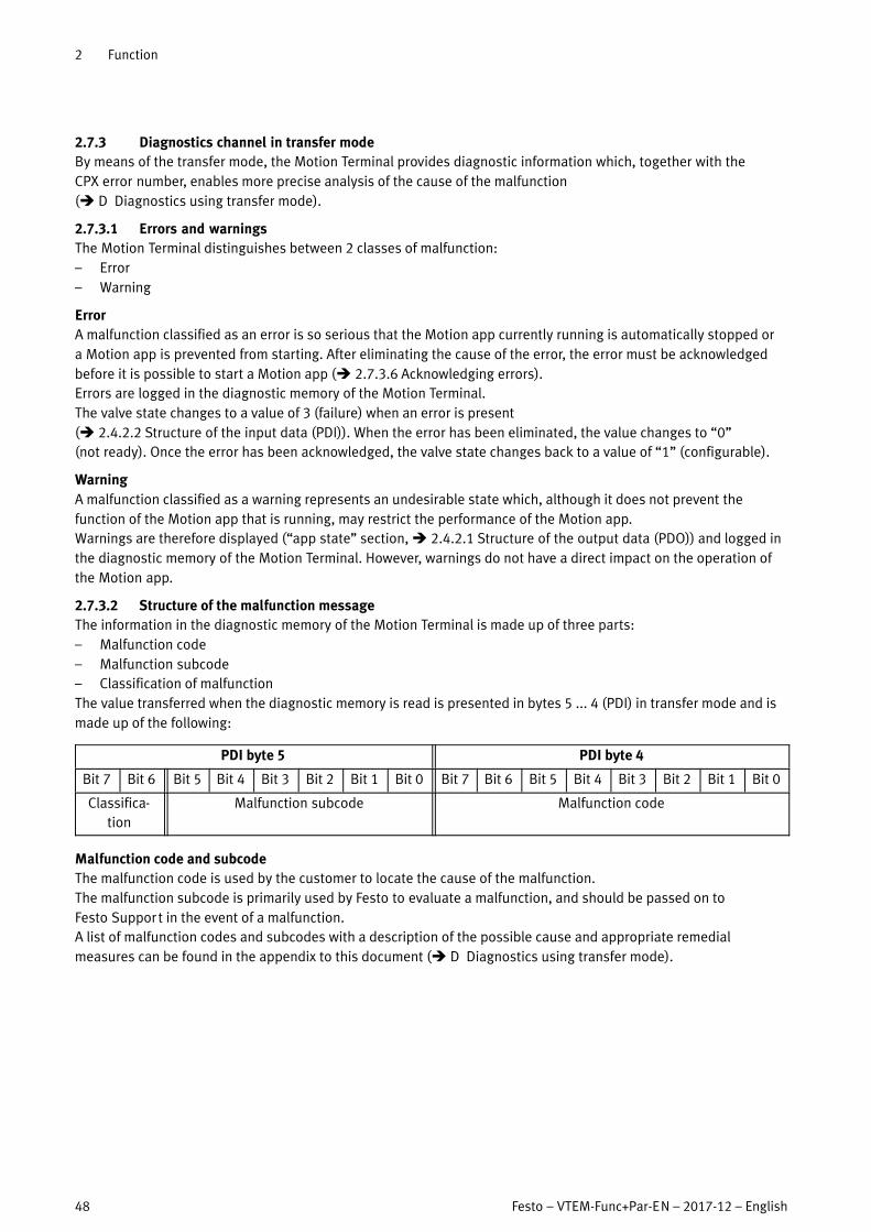
2 Function
48 Festo – VTEM-Func+Par-EN – 2017-12 – English
2.7.3 Diagnostics channel in transfer mode
By means of the transfer mode, the Motion Terminal provides diagnostic information which, together with the
CPX�error number, enables more precise analysis of the cause of the malfunction
(� D Diagnostics using transfer mode).
2.7.3.1 Errors and warnings
The Motion Terminal distinguishes between 2 classes of malfunction:
– Error
– Warning
Error
A malfunction classified as an error is so serious that the Motion app currently running is automatically stopped or
a�Motion app is prevented from starting. After eliminating the cause of the error, the error must be acknowledged
before it is possible to start a Motion app (� 2.7.3.6 Acknowledging errors).
Errors are logged in the diagnostic memory of the Motion Terminal.
The valve state changes to a value of 3 (failure) when an error is present
(� 2.4.2.2 Structure of the input data (PDI)). When the error has been eliminated, the value changes to “0”
(not�ready). Once the error has been acknowledged, the valve state changes back to a value of “1” (configurable).
Warning
A malfunction classified as a warning represents an undesirable state which, although it does not prevent the
function of the Motion app that is running, may restrict the performance of the Motion app.
Warnings are therefore displayed (“app state” section, � 2.4.2.1 Structure of the output data (PDO)) and logged in
the diagnostic memory of the Motion Terminal. However, warnings do not have a direct impact on the operation of
the Motion app.
2.7.3.2 Structure of the malfunction message
The information in the diagnostic memory of the Motion Terminal is made up of three parts:
– Malfunction code
– Malfunction subcode
– Classification of malfunction
The value transferred when the diagnostic memory is read is presented in bytes 5 ... 4 (PDI) in transfer mode and is
made up of the following:
PDI byte 5 PDI byte 4
Bit 7 Bit 6 Bit 5 Bit 4 Bit 3 Bit 2 Bit 1 Bit 0 Bit 7 Bit 6 Bit 5 Bit 4 Bit 3 Bit 2 Bit 1 Bit 0
Classifica
tion
Malfunction subcode Malfunction code
Malfunction code and subcode
The malfunction code is used by the customer to locate the cause of the malfunction.
The malfunction subcode is primarily used by Festo to evaluate a malfunction, and should be passed on to
Festo�Support in the event of a malfunction.
A list of malfunction codes and subcodes with a description of the possible cause and appropriate remedial
measures can be found in the appendix to this document (� D Diagnostics using transfer mode).

2 Function
Festo – VTEM-Func+Par-EN – 2017-12 – English 49
Malfunction subcode
Classification of malfunction
Malfunctions in the diagnostic memory of the Motion Terminal are assigned one of the following classifications.
The classification of the malfunction is given by bits 7 ... 6 in byte 5 (PDI)
PDI byte 5
Bit 7 Bit 6 Bit 5 Bit 4 Bit 3 Bit 2 Bit 1 Bit 0
Classification Significance Bit 7 Bit 6 Dec.
Reserved – 0 0 0
Active error The malfunction is classified as an error. The cause of the error is still
present.
0 1 1
Inactive error The malfunction is classified as an error. The cause of the error is no
longer present, but the error has not been acknowledged
(� 2.7.3.6 Acknowledging errors)
1 0 2
Warning The malfunction is classified as a warning. 1 1 3
Tab. 2.65
2.7.3.3 Structure of the VTEM diagnostic memory
The diagnostic memory for the Motion Terminal can accommodate up to 40 malfunction messages and is filled
chronologically. Here, a new malfunction message always appears in position 1, and existing messages are moved
‘back’ by one position (previous position number + 1).
If there are already 40 malfunction messages stored in the diagnostic memory, and a new message is added, the
earliest message at position 40 is overwritten.
Information about the content of the diagnostic memory is available at positions 253 ... 255:
Position Contents
253 Position of the most recent diagnostic message of type “error”
254 Position of the earliest diagnostic message of type “error”
255 Number of diagnostic messages in the diagnostic memory
Tab. 2.66
Example
The table below shows possible content of the diagnostic memory. This contains 3 malfunction messages. The most
recent malfunction message at position 1 is classified as an error.
Position Contents Value dec. Significance
1 01|000000|00001010 1 | 0 | 10 Active error | malfunction subcode 0 | short circuit in one of the
connected sensors on input module 1
2 11|000100|01001110 3 | 4 | 78 Warning | malfunction subcode 4 | PLC command invalid
3 11|000101|01001110 3 | 5 | 78 Warning | malfunction subcode 5 | PLC command invalid
… 00|000000|00000000 0 | 0 | 0 No malfunction message
40 00|000000|00000000 0 | 0 | 0 No malfunction message
41 … 252 00|000000|00000000 0 | 0 | 0 Not used
253 00 000000 00000001 1 The most recent error message is at position 1
254 00 000000 00000000 1 The earliest error message is at position 11)
255 00 000000 00000011 3 There are 3 malfunction messages in the diagnostic memory
1) The most recent and the earliest error message are therefore identical; there is only 1 error message in the diagnostic memory.
Tab. 2.67

2 Function
50 Festo – VTEM-Func+Par-EN – 2017-12 – English
2.7.3.4 Behaviour when an error occurs
When an error occurs, the valve is brought to a stop (valve state = 3 (failure)). No further errors are recorded in the
diagnostic memory.
If the error is no longer present, the valve state changes to “not ready” (valve state = 0).
After acknowledging the error, the valve state changes to “configurable” (valve state = 1) (� 2.7.3.6).
2.7.3.5 Readout of the diagnostic memory
The diagnostic memory is read out using the transfer mode (valve mode = 63). The sections of process data are
used as follows:
– Valve mode: 63 (transfer mode active) (PDO byte 0 bits 5 … 0 => 1111112)
– Channel: 31 (malfunctions) (PDO byte 1 bits 4 … 0 => 111112)
– Transfer control: 2 (upload) (PDO byte 1 bits 7 … 5 => 0102)
– Addressed Motion app: 0 (PDO byte 2 => 0)
– Index: position in diagnostic memory having the value that is to be read out (� 2.7.3.3)
(PDO byte 3 => 1 … 40, 253 … 255)
– Value: 0 (PDO byte 5 … 4 => 0)
Example of output data for reading out the most recent entry in the diagnostic memory
The starting point is the example content of a diagnostic memory in section � 2.7.3.3.
PDO byte 1 PDO byte 0
Command
Bit 7 Bit 6 Bit 5 Bit 4 Bit 3 Bit 2 Bit 1 Bit 0 Bit 7 Bit 6 Bit 5 Bit 4 Bit 3 Bit 2 Bit 1 Bit 0
0 1 0 1 1 1 1 1 … … 1 1 1 1 1 1
transfer control = 2 channel = 31 – valve mode = 63 (transfer mode)
PDO byte 3 PDO byte 2
Parameter
Bit 7 Bit 6 Bit 5 Bit 4 Bit 3 Bit 2 Bit 1 Bit 0 Bit 7 Bit 6 Bit 5 Bit 4 Bit 3 Bit 2 Bit 1 Bit 0
0 0 0 0 0 0 0 1 0 0 0 0 0 0 0 0
index = 1 addressed Motion app = 0
PDO byte 5 PDO byte 4
Value
Bit 15 Bit 14 Bit 13 Bit 12 Bit 11 Bit 10 Bit 9 Bit 8 Bit 7 Bit 6 Bit 5 Bit 4 Bit 3 Bit 2 Bit 1 Bit 0
0 0 0 0 0 0 0 0 0 0 0 0 0 0 0 0
value = 0

2 Function
Festo – VTEM-Func+Par-EN – 2017-12 – English 51
Example of input data having the content of the most recent entry in the diagnostic memory
The starting point is the example content of a diagnostic memory in section � 2.7.3.3.
PDI byte 1 PDI byte 0
Command
Bit 7 Bit 6 Bit 5 Bit 4 Bit 3 Bit 2 Bit 1 Bit 0 Bit 7 Bit 6 Bit 5 Bit 4 Bit 3 Bit 2 Bit 1 Bit 0
0 1 0 1 1 1 1 1 … … 1 1 1 1 1 1
transfer control = 2 channel = 31 valve state valve mode = 63 (transfer mode)
PDI byte 3 PDI byte 2
Parameter
Bit 7 Bit 6 Bit 5 Bit 4 Bit 3 Bit 2 Bit 1 Bit 0 Bit 7 Bit 6 Bit 5 Bit 4 Bit 3 Bit 2 Bit 1 Bit 0
0 0 0 0 0 0 0 1 0 0 0 0 0 0 0 0
index = 1 addressed Motion app = 0
PDI byte 5 PDI byte 4
Classifica
tion
Malfunction subcode Malfunction code
Bit 15 Bit 14 Bit 13 Bit 12 Bit 11 Bit 10 Bit 9 Bit 8 Bit 7 Bit 6 Bit 5 Bit 4 Bit 3 Bit 2 Bit 1 Bit 0
0 1 0 0 0 0 0 0 0 0 0 0 1 0 1 0
1 (active
error)
0 (no malfunction subcode) 10 (short circuit in one of the connected sensors
at input module 2)
2.7.3.6 Acknowledging errors
To change the valve state from “0” (not ready) to “1” (configurable), the error must be acknowledged once the cause
has been eliminated.
1. End transfer mode by setting the transfer control (PDO byte 1 bits 7 ... 5) to a value of 3.
The valve switches to mode (valve mode) 61, valve state is “failure” (value 3).
2. Eliminate fault.
Valve state changes to “not ready” (value 0).
3. Set valve mode (PDO byte 0 bits 5 … 0) to value “62” (“acknowledge error”).
Valve state changes to “configurable” (value 1).
Acknowledgement deletes all entries in the malfunction list.

2 Function
52 Festo – VTEM-Func+Par-EN – 2017-12 – English
Acknowledging errors without using the diagnostic memory
If the error can be eliminated without using the diagnostic memory (and hence the transfer mode), the following
simplified procedure results:
– An error is present. Content of process input data:
PDI byte 0
Bit 7 Bit 6 Bit 5 Bit 4 Bit 3 Bit 2 Bit 1 Bit 0
valve state valve mode
1 1 0 0 0 0 0 1
(failure) (ID of Motion App #01)
– The cause of the error has been eliminated. Content of process input data:
PDI byte 0
Bit 7 Bit 6 Bit 5 Bit 4 Bit 3 Bit 2 Bit 1 Bit 0
valve state valve mode
0 0 0 0 0 0 0 1
(not ready) (ID of Motion App #01)
– The error is acknowledged. Set the process output data “valve mode” to 62:
PDO byte 0
Bit 7 Bit 6 Bit 5 Bit 4 Bit 3 Bit 2 Bit 1 Bit 0
app control valve mode
0 0 1 1 1 1 1 0
… 62 (acknowledge error)
– The valve is once more ready. Content of process input data:
PDI byte 0
Bit 7 Bit 6 Bit 5 Bit 4 Bit 3 Bit 2 Bit 1 Bit 0
valve state valve mode
0 1 0 0 0 0 0 1
(configurable) (ID of Motion App #01)
After acknowledging the error, a Motion app or transfer mode can be started.

3 Parameterisation
Festo – VTEM-Func+Par-EN – 2017-12 – English 53
3 Parameterisation
In this chapter, parameterisation refers to the transfer of system and application parameters from the higher-order
controller (PLC) to the Motion Terminal VTEM.
The transfer mode of the Motion Terminal is used to transfer the parameter values (� 2.4.4 Transfer mode).
In addition to the approach described here, it is also possible to set up the parameters of the
Motion�Terminal using the WebConfig user interface.
Parameterisation that has been created using the WebConfig interface and saved on the Motion Terminal
controller can be transferred to the higher-order controller using the upload function.
3.1 Setting system and application parameters
System and application parameters are set using the transfer mode (� 2.4.4 Transfer mode).
3.1.1 Prerequisites
– The Motion Terminal boot procedure is completed.
– There are no Motion apps currently running on the valve in question (valve state is not equal to “2” (running)).
3.1.2 Procedure
To transfer system and application parameters, the following settings must be selected in the transfer mode:
– Valve mode: 63 (transfer mode active) (PDO byte 0 bits 5 … 0 => 1111112)
– Channel: 1 … 5 (ID of the parameter set for which the parameter is to be defined)
(PDO byte 1 bits 4 … 0 => 000012 … 001012)
– Transfer control: 1 (download) (PDO byte 1 bits 7 … 5 => 0012)
– Addressed Motion app: 0 … 60 (PDO byte 2 => 010 … 6010)
0 for setting system parameters (independent of Motion app)
60 for the application parameter 255 (Motion app to be taught-in) used by the teach-in run
– Index: ID of the parameter that is to be set (PDO byte 3 => 1210 … 25510)
– Value: value to be written to the parameter (PDO bytes 5 … 4).
Compared to the representation in section � 2.3.3, the ranges of values for the parameters may be
restricted by the respective Motion app used. The specific ranges of values for each Motion app is
described in the description for the Motion app in question.

3 Parameterisation
54 Festo – VTEM-Func+Par-EN – 2017-12 – English
Example
The system parameter “Tube I.D. at (2)” (ID 14) needs to be parameterised in parameter set 2 for a tube internal
diameter of 5.7 mm.
PDO byte 1 PDO byte 0
Command
Bit 7 Bit 6 Bit 5 Bit 4 Bit 3 Bit 2 Bit 1 Bit 0 Bit 7 Bit 6 Bit 5 Bit 4 Bit 3 Bit 2 Bit 1 Bit 0
0 0 1 0 0 0 1 0 0 0 1 1 1 1 1 1
transfer control = 1
(download)
channel = 2
(parameter set 2)
– valve mode = 63 (transfer mode)
PDO byte 3 PDO byte 2
Parameter
Bit 7 Bit 6 Bit 5 Bit 4 Bit 3 Bit 2 Bit 1 Bit 0 Bit 7 Bit 6 Bit 5 Bit 4 Bit 3 Bit 2 Bit 1 Bit 0
0 0 0 0 1 1 1 0 0 0 0 0 0 0 0 0
index = 14
(parameter ID 14)
addressed Motion app = 0
(system parameter)
PDO byte 5 PDO byte 4
Value
Bit 15 Bit 14 Bit 13 Bit 12 Bit 11 Bit 10 Bit 9 Bit 8 Bit 7 Bit 6 Bit 5 Bit 4 Bit 3 Bit 2 Bit 1 Bit 0
0 0 0 1 0 1 1 0 0 1 0 0 0 1 0 0
value = 570
(570 × 0.01 mm = 5.7 mm)
The values are displayed in the corresponding sections of the input data (PDI) for confirmation
(� 2.4.4.1 Structure of the process data in transfer mode).
3.2 Reading out system and application parameters
System and application parameters are read out using the transfer mode (� 2.4.4 Transfer mode).
3.2.1 Prerequisites
– The Motion Terminal boot procedure is completed.
– There are no Motion apps currently running on the valve in question (valve state “2” (running)).
3.2.2 Procedure
To read out values for system and application parameters, the following settings must be selected in the transfer
mode:
– Valve mode: 63 (transfer mode active) (PDO byte 0 bits 5 … 0 => 1111112)
– Channel: 1 … 5 (ID of the parameter set from which a parameter value is to be read out)
(PDO byte 1 bits 4 … 0 => 000012 … 001012)
– Transfer control: 2 (upload) (PDO byte 1 bits 7 … 5 => 0102)
– Addressed Motion app: 0 … 60 (PDO byte 2 => 010 … 6010)
0 for reading out system parameters (independent of Motion app)
60 for the application parameter 255 (Motion app to be taught-in) used by the teach-in run
– Index: ID of the parameter, the value of which is to be read out (PDO byte 3 => 1210 … 25510)
– Value: 0 (PDO byte 5 … 4 => 0)

3 Parameterisation
Festo – VTEM-Func+Par-EN – 2017-12 – English 55
Example
The value of the application parameter “Travel time, advancing” (ID 121) for Motion App #07 in parameter set 4 is to
be read out.
PDO byte 1 PDO byte 0
Command
Bit 7 Bit 6 Bit 5 Bit 4 Bit 3 Bit 2 Bit 1 Bit 0 Bit 7 Bit 6 Bit 5 Bit 4 Bit 3 Bit 2 Bit 1 Bit 0
0 1 0 0 0 1 0 0 0 0 1 1 1 1 1 1
transfer control = 2
(upload)
channel = 4
(parameter set 4)
– valve mode = 63 (transfer mode)
PDO byte 3 PDO byte 2
Parameter
Bit 7 Bit 6 Bit 5 Bit 4 Bit 3 Bit 2 Bit 1 Bit 0 Bit 7 Bit 6 Bit 5 Bit 4 Bit 3 Bit 2 Bit 1 Bit 0
0 1 1 1 1 0 0 1 0 0 0 0 0 1 1 1
index = 121
(parameter ID 121)
addressed Motion app = 7
(Motion App #07)
PDO byte 5 PDO byte 4
Value
Bit 15 Bit 14 Bit 13 Bit 12 Bit 11 Bit 10 Bit 9 Bit 8 Bit 7 Bit 6 Bit 5 Bit 4 Bit 3 Bit 2 Bit 1 Bit 0
0 0 0 0 0 0 0 0 0 0 0 0 0 0 0 0
value = 0
(upload)
The value of the application parameter is given by the input data in byte 5 ... 4 (PDI).
PDI byte 1 PDI byte 0
Command
Bit 7 Bit 6 Bit 5 Bit 4 Bit 3 Bit 2 Bit 1 Bit 0 Bit 7 Bit 6 Bit 5 Bit 4 Bit 3 Bit 2 Bit 1 Bit 0
0 1 0 0 0 1 0 0 … … 1 1 1 1 1 1
transfer control = 2
(upload)
channel = 4
(parameter set 4)
valve state valve mode = 63 (transfer mode)
PDI byte 3 PDI byte 2
Parameter
Bit 7 Bit 6 Bit 5 Bit 4 Bit 3 Bit 2 Bit 1 Bit 0 Bit 7 Bit 6 Bit 5 Bit 4 Bit 3 Bit 2 Bit 1 Bit 0
0 1 1 1 1 0 0 1 0 0 0 0 0 1 1 1
index = 121
(parameter ID 121)
addressed Motion app = 7
(Motion App #07)
PDI byte 5 PDI byte 4
Value
Bit 15 Bit 14 Bit 13 Bit 12 Bit 11 Bit 10 Bit 9 Bit 8 Bit 7 Bit 6 Bit 5 Bit 4 Bit 3 Bit 2 Bit 1 Bit 0
0 1 0 0 1 1 1 0 0 0 1 0 0 0 0 0
value = 100
(100× 0.01 s = 1 s)

3 Parameterisation
56 Festo – VTEM-Func+Par-EN – 2017-12 – English
3.3 Saving parameterisation as persistent data
Saving parameterisation on the Motion Terminal controller as persistent data is described in section
� 2.4.4.3.
Even in the case where the parameterisation is transferred to the Motion Terminal controller by the
higher-order controller at every system start, this parameterisation should additionally be saved once,
as�persistent data, on the Motion Terminal controller. Otherwise, the teach-in data determined during
a�teach-in run or the reference value for a Motion app may be lost (� 2.6.7 Saving the teach-in data).
3.4 Changing parameter set
Changing the active parameter set is controlled using the “valve setting” channel (channel = 15).
The “Value” section contains the number of the parameter set to be activated.
Example
Parameter set 4 is to be selected as the active parameter set.
Output data:
PDO byte 1 PDO byte 0
Command
Bit 7 Bit 6 Bit 5 Bit 4 Bit 3 Bit 2 Bit 1 Bit 0 Bit 7 Bit 6 Bit 5 Bit 4 Bit 3 Bit 2 Bit 1 Bit 0
0 0 1 0 1 1 1 1 0 0 1 1 1 1 1 1
transfer control = 1
(download)
channel = 15
(valve setting)
– valve mode = 63 (transfer mode)
PDO byte 3 PDO byte 2
Parameter
Bit 7 Bit 6 Bit 5 Bit 4 Bit 3 Bit 2 Bit 1 Bit 0 Bit 7 Bit 6 Bit 5 Bit 4 Bit 3 Bit 2 Bit 1 Bit 0
0 0 1 0 1 1 1 1 0 0 1 1 1 1 1 1
index = 1 (chosen parameter set) addressed Motion app = 0
PDO byte 5 PDO byte 4
Value
Bit 15 Bit 14 Bit 13 Bit 12 Bit 11 Bit 10 Bit 9 Bit 8 Bit 7 Bit 6 Bit 5 Bit 4 Bit 3 Bit 2 Bit 1 Bit 0
0 0 0 0 0 0 0 0 0 0 0 0 0 1 0 0
value = 4

3 Parameterisation
Festo – VTEM-Func+Par-EN – 2017-12 – English 57
Transfer is confirmed in the input data:
PDI byte 1 PDI byte 0
Command
Bit 7 Bit 6 Bit 5 Bit 4 Bit 3 Bit 2 Bit 1 Bit 0 Bit 7 Bit 6 Bit 5 Bit 4 Bit 3 Bit 2 Bit 1 Bit 0
0 0 1 0 1 1 1 1 … … 1 1 1 1 1 1
transfer control = 1
(download)
channel = 15
(valve setting)
valve state valve mode = 63 (transfer mode)
PDI byte 3 PDI byte 2
Parameter
Bit 7 Bit 6 Bit 5 Bit 4 Bit 3 Bit 2 Bit 1 Bit 0 Bit 7 Bit 6 Bit 5 Bit 4 Bit 3 Bit 2 Bit 1 Bit 0
0 0 1 0 1 1 1 1 0 0 1 1 1 1 1 1
index = 1 (chosen parameter set) addressed Motion app = 0
PDI byte 5 PDI byte 4
Value
Bit 15 Bit 14 Bit 13 Bit 12 Bit 11 Bit 10 Bit 9 Bit 8 Bit 7 Bit 6 Bit 5 Bit 4 Bit 3 Bit 2 Bit 1 Bit 0
0 0 0 0 0 0 0 0 0 0 0 0 0 1 0 0
value = 4

A Technical appendix
58 Festo – VTEM-Func+Par-EN – 2017-12 – English
A Technical appendix
A.1 Technical data
A.1.1 General information
Feature Specification/value
Operating medium Compressed air to ISO 8573-1:2010 [7:4:4],
inert�gasesPilot medium
Note about the operating/pilot medium Lubricated operation not possible
Nominal operating pressure/pilot pressure [bar] 6
Operating pressure [bar] 3 … 8
Pilot pressure [bar] 3 … 8
Notes on operating pressure [bar] 0 … 8 with external pilot air
Vacuum operation only at (3)
Flow rate per valve [l/min] 480 ±15 %
Flow direction Non-reversible
Pneumatic interfaces
Air ports (2) and (4) G1/8
Pilot air (14) M5
Valve connection (1) and (3) G3/8
Pilot exhaust air (84) M7
Pressure compensation (L) M7
Vibration and shock resistance � Assembly instruction CPX_VTEM
Tab. A.1
A.1.2 Power supply
Feature Specification/value
UEL/SEN VVAL
Operating voltage (via CPX terminal)
Nominal voltage [V DC] 24
Voltage range [V DC] 18 … 30
Intrinsic current consumption VTEM at 24 V DC typ.
Controller + linking [mA] 115 85
Per valve [mA] 28 24
Analogue input module1) [mA] 12 0
Digital input module1) [mA] 12 0
Per switched input [mA] 15 0
Electrical isolation UEL/SEN and UVAL Yes, with separate supply at the CPX terminal
Functional earth (FE) To be connected on the CPX and VTEM sides
1) Plus own consumption of the sensors
Tab. A.2
A.1.3 Operating and environmental conditions
Ambient conditions
Permitted temperature range
Long-term storage [°C] –20 … +40
Operation [°C] –5 … +50
Medium [°C] –5 … +50
Relative air humidity [%] 0 … 90
Degree of protection IP651)

A Technical appendix
Festo – VTEM-Func+Par-EN – 2017-12 – English 59
Ambient conditions
Corrosion resistance CRC
� www.festo.com/sp � Search for “CRC”
� Expert knowledge
Moderate protection (CRC 2)1)
CE marking
(declaration of conformity � www.festo.com/sp)
To EU EMC Directive
(The product is intended for use in industrial
environments. When used outside an industrial
environment, e.g. in commercial and mixed
residential areas, measures for radio interference
suppression may be necessary.)
1) To ensure the degree of protection IP65, use cover caps, blanking plugs, and inspection covers to seal off unused ports. Degree of protection
IP65 is not ensured when using the Ethernet port.
2) Moderate corrosion stress. Internal application in which condensation can occur. External visible parts with primarily decorative surface
requirements which are in direct contact with a normal industrial environment.
Tab. A.3 Technical data: Ambient conditions
A.1.4 Input modules
General
Feature Specification/value
Maximum length of the connected cables [m] 30
Fuse protection Internal electronic fuse per module
Galvanic isolation between the inputs None
Tab. A.4
Digital input module CTMM-…-D-…
Feature Specification/value
Interface M8, 3-pin
Characteristics Voltage input 24 V DC
Switching level Signal 0 [V DC] � 5
Signal 1 [V DC] � 11
Input characteristic To IEC 1131-2
Switching logic PNP, NO (normally open)
Tab. A.5
Analogue input module CTMM-…-A-…
Feature Specification/value
Interface M8, 4-pin
Characteristics Current input 4 … 20 mA
Compatible sensors Festo SDAP-...-M50-...-M8
Tab. A.6

B Glossary
60 Festo – VTEM-Func+Par-EN – 2017-12 – English
B Glossary
Term/abbreviation Description
Application parameters describe the application of the Motion app (moving mass, travel time, minimum force,etc.). Application parameters can be stored separately on each valve for each Motion app.
Controller The Motion Terminal controller forms the interface between the CPX terminal and thecomponents of the Motion Terminal.
GSDML Device description file in XML format � www.festo.com/sp
Motion app (MA) A Motion app converts parameter and setpoint specifications into control commands atthe corresponding valve.
Motion Terminal The Motion Terminal VTEM provides a range of pneumatic open-loop and closed-loopcontrol functions that are executed in the form of Motion apps.
Parameter set The system parameters of a parameter set apply jointly to all Motion apps running ona�valve, but are not used by all Motion apps.
PDI Process data input to the higher-order controller: status and states
PDO Process data output from the higher-order controller: configurations and specifications
Process data Cyclic data that are gained from a technical process by means of sensors. Process data
represent the actual values of the Motion Terminal and of the connected peripherals.
System parameters describe the components that are connected to the Motion Terminal (tubes, drive,mounting position, etc.). System parameters apply to a valve and hence jointly to allMotion apps running on this valve.
Teach-in run Teach-in process to determine the characteristics of the connected peripherals and toachieve the desired result during movement.
Transfer mode Transfer of parameters, diagnostic information and settings for the valves
WebConfig The product has no mechanical control components for commissioning and functionaltesting (manual override). Parameters and setpoint values are set solely via theWebConfig user interface or using the higher-order controller (PLC).
The WebConfig interface can be opened with a web browser if there is an existing Ethernetconnection to the controller of the Motion Terminal.
Tab. B.1 Terms and abbreviations

C Supported peripherals
Festo – VTEM-Func+Par-EN – 2017-12 – English 61
C Supported peripherals
C.1 Supported CPX bus nodes
The CPX terminal can establish the connection to a higher-order controller by means of one of the following bus
nodes:
Type code Designation Protocol
CPX-FB13 Bus node Profibus DP
CPX-FB33/FB34 Bus node PROFINET
CPX-FB36 Bus node Ethernet/IP, Modbus/TCP
CPX-FB37 Bus node EtherCAT
Tab. C.1
C.2 List of supported drives
This list contains all Festo drives approved for the Motion Terminal and the corresponding value that must be
entered in the “drive type” system parameter (ID 20) in order to be able to operate the respective drive with
a�Motion app.
List last updated: 2017-12-01
List of values for Festo drives
Drive/volume Value for “drive type” system parameter
No drive (volume, e.g. air reservoir) -1
Default value
(must be replaced with the value for one of the listed
drive types before using a corresponding Motion app)
0
ADN100...APA 641
ADN100...APPSA 902
ADN100...IPA 641
ADN100...IPPSA 902
ADN125...APA 642
ADN125...IPA 642
ADN25...APA 635
ADN25...APPSA 1458
ADN25...IPA 635
ADN25...IPPSA 1458
ADN32...APA 636
ADN32...APPSA 901
ADN32...IPA 636
ADN32...IPPSA 901
ADN40...APA 637
ADN40...APPSA 1260
ADN40...IPA 637
ADN40...IPPSA 1260
ADN50...APA 638
ADN50...APPSA 907
ADN50...IPA 638
ADN50...IPPSA 907
ADN63...APA 639
ADN63...APPSA 1327

C Supported peripherals
62 Festo – VTEM-Func+Par-EN – 2017-12 – English
List of values for Festo drives
Drive/volume Value for “drive type” system parameter
ADN63...IPA 639
ADN63...IPPSA 1327
ADN80...APA 640
ADN80...APPSA 1101
ADN80...IPA 640
ADN80...IPPSA 1101
ADVC25...AP 701
ADVC25...APA 613
ADVC32...AP 702
ADVC32...APA 614
ADVC40...AP 703
ADVC40...APA 615
ADVC50...AP 704
ADVC50...APA 616
ADVC63...AP 705
ADVC63...APA 617
CRDSNU25...PA 1413
CRDSNU25...PPSA 1425
CRDSNU25...PPVA 1419
CRDSNU32...PA 1414
CRDSNU32...PPSA 1426
CRDSNU32...PPVA 1420
CRDSNU40...PA 1415
CRDSNU40...PPSA 1427
CRDSNU40...PPVA 1421
CRDSNU50...PA 1416
CRDSNU50...PPSA 1428
CRDSNU50...PPVA 1422
CRDSNU63...PA 1417
CRDSNU63...PPSA 1429
CRDSNU63...PPVA 1423
DFM25...BPAG F 775
DFM25...BPAG FAJEJ 776
DFM25...BPAKF 778
DFM25...BPAKFA JEJ 779
DFM25...BPPVAG F 685
DFM25...BPPVAKF 765
DFM25...BYSRWGF 774
DFM25...BYSRWKF 777
DFM25...PAGF 392
DFM25...PAKF 495
DFM32...BPAG F 781
DFM32...BPAG FAJEJ 782
DFM32...BPAKF 784
DFM32...BPAKFA JEJ 785
DFM32...BPPVAG F 686
DFM32...BPPVAKF 766
DFM32...BYSRWGF 780
DFM32...BYSRWKF 783
DFM32...PAGF 393
DFM32...PAKF 496

C Supported peripherals
Festo – VTEM-Func+Par-EN – 2017-12 – English 63
List of values for Festo drives
Drive/volume Value for “drive type” system parameter
DFM40...BPAG F 787
DFM40...BPAG FAJEJ 788
DFM40...BPAKF 790
DFM40...BPAKFA JEJ 791
DFM40...BPPVAG F 687
DFM40...BPPVAKF 767
DFM40...BYSRWGF 786
DFM40...BYSRWKF 789
DFM40...PAG F 394
DFM40...PAKF 497
DFM50...BPAG F 1153
DFM50...BPAKF 1151
DFM50...BPPVAG F 1157
DFM50...BPPVAKF 1155
DFM50...BYSRWKF 1159
DFM50...PAGF 395
DFM50...PAKF 498
DFM63...BPAG F 1154
DFM63...BPAKF 1152
DFM63...BPPVAG F 1158
DFM63...BPPVAKF 1156
DFM63...BYSRWKF 1160
DFM63...PAGF 489
DFM63...PAKF 499
DGC25...GFPPVA 811
DGC25...GFYSRA 813
DGC25...GFYSRWA 814
DGC25...GPPVA 812
DGC25...KFPPVA 645
DGC25...KFYSRA 815
DGC25...KFYSRWA 816
DGC32...GFPPVA 751
DGC32...GFYSRA 801
DGC32...GFYSRWA 802
DGC32...GPPVA 752
DGC32...KFPPVA 750
DGC32...KFYSRA 803
DGC32...KFYSRWA 804
DGC40...GFPPVA 805
DGC40...GFYSRA 807
DGC40...GFYSRWA 808
DGC40...GPPVA 806
DGC40...KFPPVA 753
DGC40...KFYSRA 809
DGC40...KFYSRWA 810
DGC50...GFPPVA 1012
DGC50...GFYSRA 1013
DGC50...GFYSRWA 1014
DGC50...GPPVA 1015
DGC50...KFPPVA 1016
DGC50...KFYSRA 1017

C Supported peripherals
64 Festo – VTEM-Func+Par-EN – 2017-12 – English
List of values for Festo drives
Drive/volume Value for “drive type” system parameter
DGC50...KFYSRWA 1018
DGC63...GFPPVA 1019
DGC63...GFYSRA 1020
DGC63...GFYSRWA 1021
DGC63...GPPVA 1022
DGC63...KFPPVA 1023
DGC63...KFYSRA 1024
DGC63...KFYSRWA 1025
DGCK25...PPVAGK 1452
DGCK25...PPVAGKD2 1720
DGCK32...PPVAGK 1453
DGCK32...PPVAGKD2 1716
DGCK40...PPVAG K 1454
DGCK40...PPVAG KD2 1717
DGCK50...PPVAGK 1455
DGCK50...PPVAGKD2 1718
DGCK63...PPVAGK 1456
DGCK63...PPVAGKD2 1719
DGRFCGF25...PAR 1384
DGRFCGF25...PARA3 1393
DGRFCGF32...PAR 1385
DGRFCGF32...PARA3 1394
DGRFCGF32...PPSAR 1829
DGRFCGF32...PPVAR 1386
DGRFCGF32...PPVARA3 1395
DGRFCGF40...PPSAR 1830
DGRFCGF40...PPVAR 1387
DGRFCGF40...PPVARA3 1396
DGRFCGF50...PPSAR 1832
DGRFCGF50...PPVAR 1388
DGRFCGF50...PPVARA3 1397
DGRFCGF63...PPSAR 1835
DGRFCGF63...PPVAR 1389
DGRFCGF63...PPVARA3 1398
DGSL20...CY3A 1057
DGSL20...P1A 1050
DGSL20...PA 1049
DGSL20...Y11A 1192
DGSL20...Y3A 1057
DGSL25...CY3A 1058
DGSL25...P1A 1052
DGSL25...PA 1051
DGSL25...Y11A 1193
DGSL25...Y3A 1058
DRRD25180FHPA 1764
DRRD25180FHY10A 1805
DRRD25180FHY12A 1806
DRRD25180FHY14A 1986
DRRD25180FHY9A 1804
DRRD32180FHPA 1765
DRRD32180FHY12A 1879

C Supported peripherals
Festo – VTEM-Func+Par-EN – 2017-12 – English 65
List of values for Festo drives
Drive/volume Value for “drive type” system parameter
DRRD32180FHY14A 1987
DRRD32180FHY9A 1878
DRRD35180FHY10A 1881
DRRD35180FHY12A 1882
DRRD35180FHY9A 1880
DRRD40180FHPA 1767
DRRD40180FHY10A 1884
DRRD40180FHY12A 1885
DRRD40180FHY14A 1989
DRRD40180FHY9A 1883
DRRD50180FHY10A 1886
DRRD50180FHY12A 1887
DRRD50180FHY9A 1768
DRRD63180FHY10A 1888
DRRD63180FHY12A 1889
DRRD63180FHY9A 1769
DRVS25180P 1912
DRVS25270P 1902
DRVS2590P 1911
DRVS32180P 1914
DRVS32270P 1903
DRVS3290P 1913
DRVS40180P 1916
DRVS40270P 1904
DRVS4090P 1915
DSBC32...PAN3 1702
DSBC32...PP1AN3 1709
DSBC32...PPSAN3 1621
DSBC32...PPVAN3 1620
DSBC40...PAN3 1703
DSBC40...PP1AN3 1710
DSBC40...PPSAN3 1623
DSBC40...PPVAN3 1622
DSBC50...PAN3 1704
DSBC50...PP1AN3 1711
DSBC50...PPSAN3 1625
DSBC50...PPVAN3 1624
DSBC63...PAN3 1705
DSBC63...PP1AN3 1712
DSBC63...PPSAN3 1627
DSBC63...PPVAN3 1626
DSBCL132...PAN3 1836
DSBCL150...PAN3 1929
DSBCL163...PAN3 1931
DSBFC32...PAN3R 1688
DSBFC32...PPSAN3R 1401
DSBFC32...PPVAN3R 1400
DSBFC40...PAN3R 1689
DSBFC40...PPSAN3R 1403
DSBFC40...PPVAN3R 1402
DSBFC50...PAN3R 1690

C Supported peripherals
66 Festo – VTEM-Func+Par-EN – 2017-12 – English
List of values for Festo drives
Drive/volume Value for “drive type” system parameter
DSBFC50...PPSAN3R 1405
DSBFC50...PPVAN3R 1404
DSBFC63...PAN3R 1691
DSBFC63...PPSAN3R 1407
DSBFC63...PPVAN3R 1406
DSNU16...PA 136
DSNU16...PA+FEN 238
DSNU16...PA+FENG 247
DSNU16...PPS 1219
DSNU16...PPSA 1212
DSNU16...PPVA 124
DSNU16...PPVA+FEN 237
DSNU20...PA 137
DSNU20...PA+FEN 239
DSNU20...PA+FENG 248
DSNU20...PPS 1220
DSNU20...PPSA 1213
DSNU20...PPVA 139
DSNU20...PPVA+FEN 240
DSNU25...PA 138
DSNU25...PA+FEN 242
DSNU25...PA+FENG 251
DSNU25...PPS 1221
DSNU25...PPSA 1214
DSNU25...PPVA 123
DSNU25...PPVA+FEN 241
DSNU32...PA 833
DSNU32...PPS 1095
DSNU32...PPSA 1215
DSNU32...PPVA 837
DSNU40...PA 834
DSNU40...PPS 1094
DSNU40...PPSA 1216
DSNU40...PPVA 838
DSNU50...PA 835
DSNU50...PPS 1093
DSNU50...PPSA 1217
DSNU50...PPVA 839
DSNU63...PA 836
DSNU63...PPS 1082
DSNU63...PPSA 1218
DSNU63...PPVA 840
Tab. C.2

D Diagnostics using transfer mode
Festo – VTEM-Func+Par-EN – 2017-12 – English 67
D Diagnostics using transfer mode
The following tables contain all the malfunction codes and sub-codes relevant to the application that can be stored
in the diagnostic memory of the Motion Terminal.
Description of the diagnostic function via transfer mode � 2.7.3 Diagnostics channel in transfer mode
D.1 Error in basic system
VTEM malfunction Diagnostic message Error elimination CPX error
numberCode Sub-code
Hardware fault
1 0 Hardware fault on valve Shut down electrical and pneumatic
supply and replace valve
106
1 Piezo failure in valve
2 Voltage conversion defective in valve
3 Leakage in pilot control in valve
4 Leakage in booster in valve
5 Pressure sensor defective in valve
6 Stroke conversion defective in valve
7 Voltage too high in valve
8 Temperature sensor defective in valve
9 Production data of valve invalid
10 Valve not supported
11 Piezo offset identification failed
2 0 Hardware fault on controller Replace Motion Terminal (controller) 107
1 Atmospheric pressure sensor defective
in controller
2 Supply pressure sensor defective in
controller
3 Exhaust air sensor defective in
controller
14 Backplane ID not known
15 Backplane ID not supported
16 Atmospheric pressure sensor of
controller outside of valid range of
values
17 Supply pressure sensor of controller
outside of valid range of values
18 Exhaust pressure sensor of controller
outside of valid range of values
3 0 Hardware fault on input module 1 Shut down electrical supply and
replace input module
115
4 0 Hardware fault on input module 2 Shut down electrical supply and
replace input module
115
9 0 Short circuit in one of the connected
sensors at input module 1
Replace sensor 2
10 0 Short circuit in one of the connected
sensors at input module 2
Replace sensor 2

D Diagnostics using transfer mode
68 Festo – VTEM-Func+Par-EN – 2017-12 – English
VTEM malfunction CPX error
number
Error eliminationDiagnostic message
Code
CPX error
number
Error eliminationDiagnostic message
Sub-code
Operational fault
15 0 Over-temperature in valve Check ambient conditions and restart;
if appropriate, shut down electrical and
pneumatic supply and replace valve
75
16 0 Value range for temperature
measurement violated in controller
Check ambient conditions and restart;
if appropriate, shut down electrical and
pneumatic supply and replace valve
75/80
1 Value range for temperature
measurement violated in controller:
measured value > 85�°C
75
2 Value range for temperature
measurement violated in controller:
measured value < -20�°C
80
21 0 Error in internal communication Check ambient conditions and restart;
if appropriate, shut down electrical and
pneumatic supply and replace valve
110
1 Communication failure,
controller to�valve
2 Communication malfunction,
valve to�controller
3 Communication failure,
valve to controller
4 Communication failure,
controller to input module 1
5 Communication malfunction,
input module 1 to controller
6 Communication failure,
input module 1 to controller
7 Communication failure,
controller to input module 2
8 Communication malfunction,
input module 2 to controller
9 Communication failure,
input module 2 to controller
22 0 Error communicating with higher-order
controller (PLC)
Check PLC and connection, restart if
appropriate
110
1 Communication with higher-order
controller (PLC) interrupted
23 0 Internal software error Perform firmware update,
contact Support
115
29 0 Error list is full (new entries not
possible until errors acknowledged)
Reset error list by acknowledging
errors (valve mode 62)
Initialisation failed
30 0 Module update not possible Check hardware versions are
consistent; if appropriate, shut down
electrical and pneumatic supply and
replace module
115

D Diagnostics using transfer mode
Festo – VTEM-Func+Par-EN – 2017-12 – English 69
VTEM malfunction CPX error
number
Error eliminationDiagnostic message
Code
CPX error
number
Error eliminationDiagnostic message
Sub-code
31 0 Module update required Perform module update 231
1 Bootloader version of valve invalid
2 Software version of valve invalid
3 Bootloader version of input module 1
invalid
4 Software version of input module 1
invalid
5 Bootloader version of input module 2
invalid
6 Software version of input module 2
invalid
32 0 Incorrect configuration file Delete invalid or inconsistent
configuration file from device
100
33 0 Motion app licensing failed Contact Support 229
34 0 Version information incorrect Contact Support 115
Supply error
40 0 Malfunction of load voltage Check load voltage and cabling 5
42 0 Malfunction of pilot pressure Check pilot pressure and tubing
connection
85
Assembly fault
69 0 Input module configuration invalid Check input modules for compatibility 228
Tab. D.1
D.2 Application-specific malfunction
VTEM malfunction Diagnostic message Error elimination CPX error
numberCode Sub-code
Parameters or setting values invalid
71 0 Invalid value for a system parameter in
the range of indices 10 ... 19 (tube)
Comply with valid ranges of values for
the parameters of the Motion app
being run
72 0 Invalid value for a system parameter in
the range of indices 20 ... 39 (drive)
Comply with valid ranges of values for
the parameters of the Motion app
being run
73 0 Invalid value for a system parameter in
the range of indices 40 ... 59 (volume)
Comply with valid ranges of values for
the parameters of the Motion app
being run
74 0 Invalid value for a system parameter in
the range of indices 60 ... 69
Comply with valid ranges of values for
the parameters of the Motion app
being run
77 0 Invalid value for an application
parameter in the range of indices 100
... 255
Comply with valid ranges of values for
the parameters of the Motion app
being run
101
78 0 PLC command invalid Check command sequence in PLC
program
1 Valve mode invalid
2 App control invalid
3 App option invalid
4 Setpoint value 1 invalid
5 Setpoint value 2 invalid

D Diagnostics using transfer mode
70 Festo – VTEM-Func+Par-EN – 2017-12 – English
VTEM malfunction CPX error
number
Error eliminationDiagnostic message
Code
CPX error
number
Error eliminationDiagnostic message
Sub-code
79 0 Actual value outside of defined value
range
Interpret actual value that is output
(is�kept within the range of values)
1 Determined actual value 1 lower than
minimum of defined value range
2 Determined actual value 1 higher than
maximum of defined value range
3 Determined actual value 2 lower than
minimum of defined value range
4 Determined actual value 2 higher than
maximum of defined value range
Start condition of Motion app not met
101 0 Analogue input module not present Shut down electrical supply and install
input module
115
102 0 Digital input module not present Shut down electrical supply and install
input module
115
103 0 Drive not in required initial position Move drive to required initial position 101
1 Drive not in (correct) end position
104 0 Teach-in run not executed successfully
(no teach-in data available)
Execute teach-in run 101
105 0 Movement test not executed
successfully
Execute teach-in run 101
Supply malfunction
130 0 No supply pressure Check supply pressure and tubing
connection
105
131 0 Supply pressure too high Check supply pressure 105
Malfunction in the execution of a Motion app
140 0 Motion app malfunction: end position
speed too high
Check compliance with the functional
range of the Motion app
101
141 0 Motion app malfunction: weight force
in measurement position too high
(weight force > 75�% pneumatic force)
Check compliance with the functional
range of the Motion app
1 Motion app malfunction: measurement
position = advanced state
2 Motion app malfunction: measurement
position = retracted state
145 0 Motion app malfunction: target
pressure > supply pressure
Check compliance with the functional
range of the Motion app
1 Motion app malfunction: target
pressure > supply pressure at (2)
2 Motion app malfunction: target
pressure > supply pressure at (4)
3 Motion app malfunction: target
pressure > supply pressure at (2) + (4)

D Diagnostics using transfer mode
Festo – VTEM-Func+Par-EN – 2017-12 – English 71
VTEM malfunction CPX error
number
Error eliminationDiagnostic message
Code
CPX error
number
Error eliminationDiagnostic message
Sub-code
146 0 Motion app malfunction: target
pressure < exhaust pressure
Check compliance with the functional
range of the Motion app
1 Motion app malfunction: target
pressure < exhaust pressure at (2)
2 Motion app malfunction: target
pressure < exhaust pressure at (4)
3 Motion app malfunction: target
pressure < exhaust pressure at (2) + (4)
147 0..15 Motion app malfunction: following
error, stroke above threshold value
Check compliance with the functional
range of the Motion app
101
148 0 Motion app malfunction: unexpected
exiting of end position
Check compliance with the functional
range of the Motion app
1 Motion app malfunction: unexpected
exiting of ‘retracted’ end position ((2)
pressurised)
2 Motion app malfunction: unexpected
exiting of ‘advanced’ end position ((4)
pressurised)
149 0 Motion app malfunction: end position
not reached
Check compliance with the functional
range of the Motion app
101
1 Motion app malfunction: ‘retracted’
end position ((2) pressurised) not
reached
2 Motion app malfunction: ‘advanced’
end position ((4) pressurised) not
reached
150 0 Motion app malfunction: pressure
build-up not successful
Check compliance with the functional
range of the Motion app
101
1 Motion app malfunction: pressure
build-up not successful at (2)
2 Motion app malfunction: pressure
build-up not successful at (4)
151 0 Motion app malfunction: pressure
reduction not successful
Check compliance with the functional
range of the Motion app
101
1 Motion app malfunction: pressure
reduction not successful at (2)
2 Motion app malfunction: pressure
reduction not successful at (4)

D Diagnostics using transfer mode
72 Festo – VTEM-Func+Par-EN – 2017-12 – English
VTEM malfunction CPX error
number
Error eliminationDiagnostic message
Code
CPX error
number
Error eliminationDiagnostic message
Sub-code
Deviation from setpoint behaviour
190 0 Motion app malfunction: travel time
not achieved
Check compliance with the functional
range of the Motion app
101
1 Motion app malfunction: target travel
time for advancing ((4) pressurised)
not achieved
2 Motion app malfunction: target travel
time for retracting ((2) pressurised) not
achieved
193 0 Motion app malfunction: desired
performance may not be achievable
Check compliance with the functional
range of the Motion app
1 Motion app malfunction: target travel
time for advancing may not be
achievable
2 Motion app malfunction: target travel
time for retracting may not be
achievable
Tab. D.2
D.3 Sensor error
VTEM malfunction Diagnostic message Error elimination CPX error
numberCode Sub-code
225 0 Sensor error, front partial stroke
measurement (‘retracted’ end
position�/ (2) pressurised)
Check sensor and cabling 3
226 0 Sensor error, rear partial stroke
measurement (‘advanced’ end
position�/ (4) pressurised)
Check sensor and cabling 3
Tab. D.3

E Licences
Festo – VTEM-Func+Par-EN – 2017-12 – English 73
E Licences
This product uses open-source software. The following table lists the corresponding software packages as well as
the licences that govern the software.
Software package Licence Version number Terms of the licence
Unity MIT https://opensource.org/licenses/MIT
bbenv GPL 2.0 http://www.gnu.org/licenses/oldlicenses/gpl2.0
bootgen Xilinx
bootloader GPL 2.0+ http://www.gnu.org/licenses
busybox GPL 2.0 http://www.gnu.org/licenses/oldlicenses/gpl2.0
e2fsprogs GPL 2.0 http://www.gnu.org/licenses/oldlicenses/gpl2.0
gcovr BSD 3 https://opensource.org/licenses/BSD-3-Clause
haserl GPL 2.0 http://www.gnu.org/licenses/oldlicenses/gpl2.0
libb64 Public Domain
Certification
libev BSD 2 https://opensource.org/licenses/BSD-2-Clause
libiniparser MIT https://opensource.org/licenses/MIT
libnl LGPL 2.1 http://www.gnu.org/licenses/oldlicenses/lgpl2.1
libtool BSD 3 https://opensource.org/licenses/BSD-3-Clause
linux GPL 2.0 http://www.gnu.org/licenses/oldlicenses/gpl2.0
lua MIT https://opensource.org/licenses/MIT
luafilesystem MIT https://opensource.org/licenses/MIT
lzo GPL 2.0 http://www.gnu.org/licenses/oldlicenses/gpl2.0
mkimage GPL 2.0+ http://www.gnu.org/licenses
mtdutils GPL 2.0 http://www.gnu.org/licenses/oldlicenses/gpl2.0
sysroot LGPL 2.1 http://www.gnu.org/licenses/oldlicenses/lgpl2.1
zlib Zlib http://www.gzip.org/zlib/zlib_license.html
Tab. E.1


Reproduction, distribution or sale of this document or communication ofits contents to others without express authorization is prohibited. Offenders will be liable for damages. All rights reserved in the event that a patent, utility model or design patent is registered.
Copyright:Festo AG & Co. KGRuiter Straße 8273734 EsslingenGermany
Phone:+49 711 347-0
Fax:+49 711 347-2144
e-mail:[email protected]
Internet:www.festo.com