vtem improvements to meet exploration challenges...
TRANSCRIPT

10th SAGA Biennial Technical Meeting and Exhibition . Short Paper
VTEM improvements to meet exploration challenges demonstrated at Caber and Fox River Projects
Magdel Combrinck1, Bob Lo2
1. Geotech Airborne Ltd, South Africa, [email protected] 2. Geotech Ltd, Canada, [email protected]
INTRODUCTION Time Domain Electromagnetic (TDEM) systems are designed to induce electrical currents in the subsurface and measure the resulting electromagnetic fields. From this information earth conductivity models are produced. Applications of TDEM include mineral exploration – either in directly detecting conductive orebodies or in mapping conductors associated with non-conductive ores as well as shallow groundwater and pollution mapping. A large range of system types and platforms (air and ground) are operated commercially and the successful application of TDEM is critically dependent on choosing the optimum system and acquisition parameters for targets of interest. The "VTEM" (Versatile Time Domain EM) system offer selectable transmitter wave-form types and computer controlled power electronics and advanced signal processing software that makes the system easily adjustable to different geophysical tasks. The VTEM, as all other commercial airborne systems, records the time derivative of the magnetic field (dB/dt) with a receiver coil (effective area 113 m2). Measuring the dB/dt field has an inherent limitation when exploring for massive copper-nickel sulphide orebodies.
These targets are too conductive to have significant dB/dt responses, and are much better defined by their B-field signatures (Smith and Annan, 1998). Another advantage mentioned by Smith and Annan (1998) is the fact that the B-field excitation waveform has significantly more energy than the dB/dt power spectrum at low frequencies while the reverse is observed for high frequencies. This implies that deep seated conductors under conductive overburden will be better resolved from B-field responses. The B-field response can be measured directly using magnetometers as receivers instead of an induction coil (Foley and Leslie, 1998; Katayama et al, 2004). However, the logistical challenges associated with this approach are still preventing the commercial availablility of an airborne TDEM system directly measuring the B-field. A more practical approach at this stage is to approximate the B-field response from measured dB/dt values. Various approcahes can be followed as sufficiently summarised by Smith and Annan (2000). The VTEM system was re-configured in 2006 to provide a calculated B-field response utilising approximately 20 on-time measurements for a very accurate waveform definition. The effective increase in the target resolvability is discussed as well as examples and comparison of data aqcuired over the Fox River
ABSTRACT VTEM is a helicopter-borne Time Domain Electromagnetic (TDEM) system with concentric loop transmitter receiver geometry. The system utilises a coil as receiver, measuring the time derivative of the magnetic (dB/dt) field used to map and delineate sub-surface conductivities. However, extremely good conductors have very low dB/dt responses and are much better resolved by the induced magnetic (B) field. The B-field can either be measured directly or calculated by integrating the dB/dt response. This calculation of the B-field was recently introduced to the VTEM system. The additional benefit provided by the B-field response is illustrated over highly conductive mineral deposits. Data acquired over the Fox River Project and Caber deposits are presented as case histories and clearly demonstrate the benefit of continuing improvements in acquisition systems to provide increasing resolving capabilities for conductive targets. Key words: TDEM, VTEM, Fox River, Caber, B-field, AEM

Abbreviated title Combrinck and Lo
10th SAGA Biennial Technical Meeting and Exhibition Short Paper
Project nickel-copper sulphide and Caber zinc orebodies. THE VTEM SYSTEM The VTEM system parameters can be summarised as: Base Frequency: 30/25 Hz Waveform (TX pulse): Trapezoidal Average Dipole Moment: 220,413 Peak Dipole Moment (NIA): 500,000 EM Transmitter height: 30 metres EM Receiver height: 30 metres Configuration: Concentric loop Magnetometer height: 50 metres Survey Platform: A-Star helicopters Survey speed: 25 m/sec Rx time gates: 25 (0.12 – 7.2 ms) These parameters relate to:
• Deep penetration (750m confirmed in Athabasca Basin) associated with the large transmitter dipole moment which is the highest of the helicopter EM systems and the low Tx/Rx terrain clearance of 30m
• High spatial resolution because of a low survey speed (stations every 2.5 m)
• Symmetric anomalies due to concentric transmitter/receiver coils
• Contouring ability in areas of moderate to rugged terrain, reducing terrain effect on data
• Long pulse width (up to 7.5 ms) reducing interference of “positive ramp” decays for good conductors on the “negative ramp” response measured in the off-time.
All the above-mentioned advantages of the VTEM system ensure excellent quality dB/dt data which directly transforms to excellent quality in the calculated B-field data. Increased transmitter power (2005) and the addtion of the B-field calculation in 2006 increased the sensitivity of the system. Including B-field data in a survey extends the dynamic range of conductivities that can be resolved in a survey. CABER DEPOSIT EXAMPLE Geotech’s testing over the Caber Deposit shows the marked improvements that have been made in the VTEM system. The Caber Deposit is a zinc rich VMS deposit located in the Matagami mining camp of Quebec, Canada. It is a cigar shaped body dipping between 75˚ and 85˚ to the southwest, striking at 125˚ azimuth. The top to the body is approximately 125 meters beneath surface. The Caber deposit resources were evaluated by Roscoe Postle & Associates Inc., and estimated at: 515,000 t of indicated resources @ 11.0% Zn, 0.56% Cu, 11.1 g/t Ag and 0.14 g/t Au; 285,000 t of inferred resources @ 8.5% Zn, 0.8% Cu, 11.6 g/t Ag and 0.14 g/t Au (Théberge, D., 2006). Geotech flew the
Caber deposit in 2003 and the result is shown in Figure 1 and while an indication that an anomalous response was present, it was too noisy to have been interpreted with confidence as a valid AEM target. In 2005, Geotech surveyed the Caber Deposit with their high-power VTEM system which was introduced earlier in the year (Figure 2).
Figure 1. 2003 VTEM results over Caber. At mid and late times, there is an indication of a response, but it is only slightly higher in amplitude than the noise.
Figure 2. 2005 VTEM survey over the Caber Deposit which is clearly detected. Note that the spatial resolution of the system is also greatly improved.
Abbreviated title Combrinck and Lo
10th SAGA Biennial Technical Meeting and Exhibition Short Paper
The 2005 results show the Caber Deposit being easily detected once the response from the conductive overburden to the northwest has decayed away. The steep dip which can be interpreted from the VTEM profiles match the known orientation of the body. There is a ten times increase in the signal to noise ratio between 2003 and 2005. The increase in transmitter dipole moment from 2003 to 2005 was about two times only and the rest is due to improvements in the electronics and other patented technologies. Note that the spatial resolution is also much better, due to the decreased requirements for filtering. FOX RIVER PROJECT EXAMPLE The Fox River Project provides an example of a very good conductor (7000 S determined from UTEM) containing more than up to 45% pyrrhotite and 0.5% chalcopyrite in some horizons. It occurs in the Superior Boundary Zone and consists of sedimentary semi-massive to massive sulphides associated with ultramafic and mafic intrusions (Peck et. al., 2000). Target conductors were identified with a UTEM ground survey in 2000 and subsequent drilling has confirmed the presence and orientation of the orebody. In 2006 VTEM dB/dt and B-field data were aqcuired over the Fox River deposit as a test survey and compared with UTEM ground data and drillhole information.
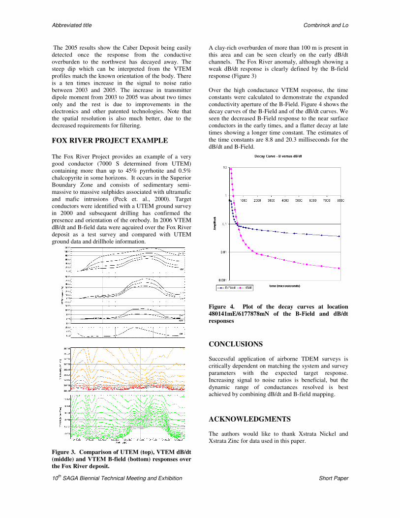
Figure 3. Comparison of UTEM (top), VTEM dB/dt (middle) and VTEM B-field (bottom) responses over the Fox River deposit.
A clay-rich overburden of more than 100 m is present in this area and can be seen clearly on the early dB/dt channels. The Fox River anomaly, although showing a weak dB/dt response is clearly defined by the B-field response (Figure 3) Over the high conductance VTEM response, the time constants were calculated to demonstrate the expanded conductivity aperture of the B-Field. Figure 4 shows the decay curves of the B-Field and of the dB/dt curves. We seen the decreased B-Field response to the near surface conductors in the early times, and a flatter decay at late times showing a longer time constant. The estimates of the time constants are 8.8 and 20.3 milliseconds for the dB/dt and B-Field.
Figure 4. Plot of the decay curves at location 480141mE/6177878mN of the B-Field and dB/dt responses CONCLUSIONS Successful application of airborne TDEM surveys is critically dependent on matching the system and survey parameters with the expected target response. Increasing signal to noise ratios is beneficial, but the dynamic range of conductances resolved is best achieved by combining dB/dt and B-field mapping. ACKNOWLEDGMENTS The authors would like to thank Xstrata Nickel and Xstrata Zinc for data used in this paper.

Abbreviated title Combrinck and Lo
10th SAGA Biennial Technical Meeting and Exhibition Short Paper
REFERENCES Arai, E., Katayama, H., Masuda, K., Hayashi, T., Ota, H., and Nagaishi, T., 2004, Development of a TDEM data acquisition system based on a SQUID magnetometer for mineral exploration. SEG Technical Program Expanded Abstracts, 696-699. Théberge, D., 2006. Concernant lapropriété :Caber - du dôme, Ressources Metco inc., Rapport technique ni 43-101 Foley, C. P., and Leslie, K. E., 1998, Potential use of high Tc SQUIDS for airborne electromagnetics: Exploration Geophysics, 29, 30–34. (Foley and Leslie, 1998; Katayama et al, 2004) Sumitomo Electric Hightechs Co., Ltd. Peck, D.C., Potter, L., Desharnais, G., Scoates, R.F.J., Corkery, M.T. and Böhm, Ch.O. 2000: Geology of the western part of the Fox River Belt (parts of NTS 53M and 53N); in Report of Activities 2000, Manitoba Industry, Trade and Mines, Manitoba Geological Survey, 38-41. Smith, R., and Annan, P., 1998, The use of B-field measurements in an airborne time-domain system: Part 1. Benefits of B-field versus dB/dt data: Exploration Geophysics, 29, 24-29. Smith, R., and Annan, P., 2000, Using an induction coil sensor to indirectly measure the B-field response in the bandwidth of the transient electromagnetic method: Geophysics, 65, 1489–1494.