module standards, third revision, winter … standards, third revision, winter 2004 ... other...
TRANSCRIPT
MODULE STANDARDS, THIRD REVISION, WINTER 2004
This manual is the product of six years of effort, education and enjoyment of Z Scale modulesbuilt for use at home and at shows. We hope you will find the concept one that you would like toconstruct for yourself.
We subscribe to the concept that model railroads are just more fun at home if they have apurpose - the prototypical pickup and delivery of goods and people from one point on a layout toanother point. We strongly encourage operational sidings and branch tracks to serve industriesand train stations for the simple pleasure of prototypical drop off and pickup of rolling stock.
When we assemble these modules together as a group, we take great delight in running longtrains our individual home layouts can not. Prototypically long trains of 50 to 100 cars are adelight to watch, and a real attention grabber at public shows. Obviously, such modules must bebuilt to some form of a "standard" to allow sections built by any modeler's to be mated with thoseof another modular.
The Z-Bend Track concept supply supports both North American and European designspowered by either (or both) DC and DCC with (our without) centenary built using all knowncommercial track products. The concept only contains minimums (radius, height, etc.) with noupper limits imposed on modelers.
Let’s examine how all this is possible.
BASIC CONCEPT:
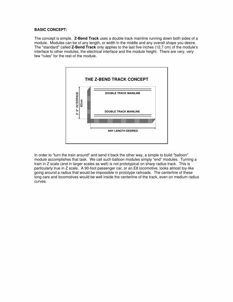
The concept is simple. Z-Bend Track uses a double track mainline running down both sides of amodule. Modules can be of any length, or width in the middle and any overall shape you desire.The "standard" called Z-Bend Track only applies to the last five inches (12.7 cm) of the module’sinterface to other modules, the electrical interface and the module height. There are very, veryfew "rules" for the rest of the module.
THE Z-BEND TRACK CONCEPT
ANY LENGTH DESIRED
DOUBLE TRACK MAINLINE
DOUBLE TRACK MAINLINE
In order to "turn the train around" and send it back the other way, a simple to build "balloon"module accomplishes that task. We call such balloon modules simply “end” modules. Turning atrain in Z scale (and in larger scales as well) is not prototypical on sharp radius track. This isparticularly true in Z scale. A 90-foot passenger car, or an E8 locomotive, looks almost toy-likegoing around a radius that would be impossible in prototype railroads. The centerline of theselong cars and locomotives would be well inside the centerline of the track, even on medium radiuscurves.

We encourage end modules to utilize the concepts of "view blocks." View blocks use buildings,tall grain elevators, trees, geology or other scenery to "hide" the train while it is in the turn. Eventhough our "logical" minds tell us the train is simply going behind an object, the train thatreappears from hiding is somehow a "different" train than the one that disappeared a secondbefore.
BALLOON "END" MODULES
R1
R2
16" MINIMUM~41cm
But end modules caps can be much more. For someone with very limited space, two endmodules can be a complete layout. However, the owner can take them to group setups, anddisplay their skills in module building right along with the rest of the participants.
MINIMAL WORKING LAYOUT
If a modeler has more room, then the construction of one, or more, modules can go between theend modules to create a larger layout to fill the available layout space at home. The extra spaceis just waiting for lots of interesting turnouts and sidings to serve all manners of passenger andfreight traffic.
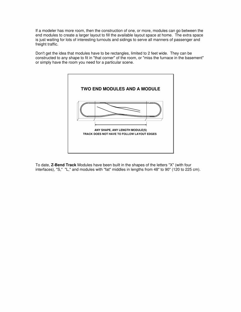
Don't get the idea that modules have to be rectangles, limited to 2 feet wide. They can beconstructed to any shape to fit in "that corner" of the room, or "miss the furnace in the basement"or simply have the room you need for a particular scene.
TWO END MODULES AND A MODULE
ANY SHAPE, ANY LENGTH MODULE(S)TRACK DOES NOT HAVE TO FOLLOW LAYOUT EDGES
To date, Z-Bend Track Modules have been built in the shapes of the letters "X" (with fourinterfaces), "S," "L," and modules with "fat" middles in lengths from 48" to 90" (120 to 225 cm).

MODULE PLANNING CONCEPTS
That brings us to one of the most important concepts of Z-Bend Track. Absolute freedom to buildthe scene you wish, without excessive forced compression, or leaving out part of the scene ordistorting a prototypical scene you wish to model.
We strongly suggest that you layout the scene first, without showing any wooded "borders"around the edge of the scene. Don't confine your thinking to a particular rectangle of wood,unless your available space requires it:
LAYOUT OUT THE SCENE FIRST
Once you have the scene completely drawn out (or on the computer screen) only then addwooden "borders" around the scene to determine what the woodworking project will be toconstruct the module. If the module frame is too complex, then you can make adjustments to thescene to simplify the module frame construction.
DETERMINE THE MODULE SHAPE SECOND
STANDARD INTERFACE
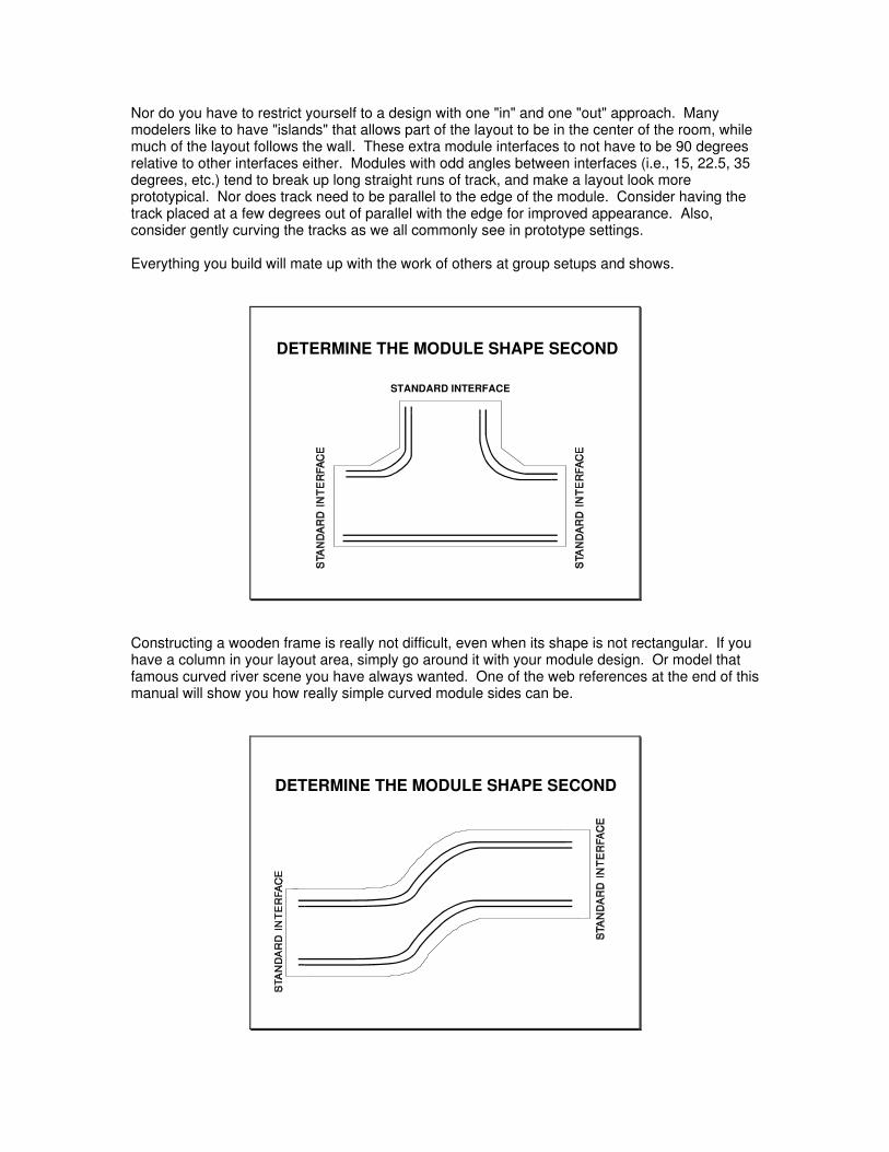
Nor do you have to restrict yourself to a design with one "in" and one "out" approach. Manymodelers like to have "islands" that allows part of the layout to be in the center of the room, whilemuch of the layout follows the wall. These extra module interfaces to not have to be 90 degreesrelative to other interfaces either. Modules with odd angles between interfaces (i.e., 15, 22.5, 35degrees, etc.) tend to break up long straight runs of track, and make a layout look moreprototypical. Nor does track need to be parallel to the edge of the module. Consider having thetrack placed at a few degrees out of parallel with the edge for improved appearance. Also,consider gently curving the tracks as we all commonly see in prototype settings.
Everything you build will mate up with the work of others at group setups and shows.
DETERMINE THE MODULE SHAPE SECOND
STANDARD INTERFACE
Constructing a wooden frame is really not difficult, even when its shape is not rectangular. If youhave a column in your layout area, simply go around it with your module design. Or model thatfamous curved river scene you have always wanted. One of the web references at the end of thismanual will show you how really simple curved module sides can be.
DETERMINE THE MODULE SHAPE SECOND

How do all these interesting shapes work out when they are transported out of the home forpublic displays? Absolutely! Actually, we find they make for the most interesting layout you canimaging. The combination of shapes adds a lot of visual interest to the assembled layout, withtrains twisting and turning just like we see them in real life.
MODULE SHAPES AND BRANCHING
EM EXTRA WIDE "T" "L"
"L"
Z-BEND TRACK PERMITS ALL
EM
EM = ENDMODULE
"S"EM
At public shows, the area set aside for displays may not be the perfect shape for setting up alayout. By using the wonderful module shapes the owner's built, the layout can be configured togo around existing doors, columns or other obstructions. This frequently occurs, and theassembled layout almost looks like it was build specifically for this particular show area.
MODULE HEIGTH
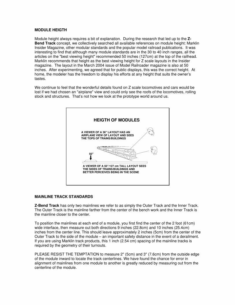
Module height always requires a bit of explanation. During the research that led up to the Z-Bend Track concept, we collectively searched all available references on module height: MarklinInsider Magazine, other modular standards and the popular model railroad publications. It wasinteresting to find that although many module standards are in the 30 to 40 inch ranges, all thearticles on the "best viewing height" recommended 50 inches (127cm) at the top of the railhead.Marklin recommends that height as the best viewing height for Z scale layouts in the Insidermagazine. The layout in the March 2004 issue of Model Railroader magazine is also at 50inches. After experimenting, we agreed that for public displays, this was the correct height. Athome, the modeler has the freedom to display his efforts at any height that suits the owner’stastes.
We continue to feel that the wonderful details found on Z scale locomotives and cars would belost if we had chosen an "airplane" view and could only see the roofs of the locomotives, rollingstock and structures. That’s not how we look at the prototype world around us.
HEIGTH OF MODULES
A VIEWER OF A 36" LAYOUT HAS ANAIRPLANE VIEW OF LAYOUT AND SEES
A VIEWER OF A 50”/127 cm TALL LAYOUT SEESTHE SIDES OF TRAINS/BUILDINGS ANDBETTER PERCEIVES BEING IN THE SCENE
THE TOPS OF TRAINS/BUILDINGS
50"
MAINLINE TRACK STANDARDS
Z-Bend Track has only two mainlines we refer to as simply the Outer Track and the Inner Track.The Outer Track is the mainline farther from the center of the bench work and the Inner Track isthe mainline closer to the center.
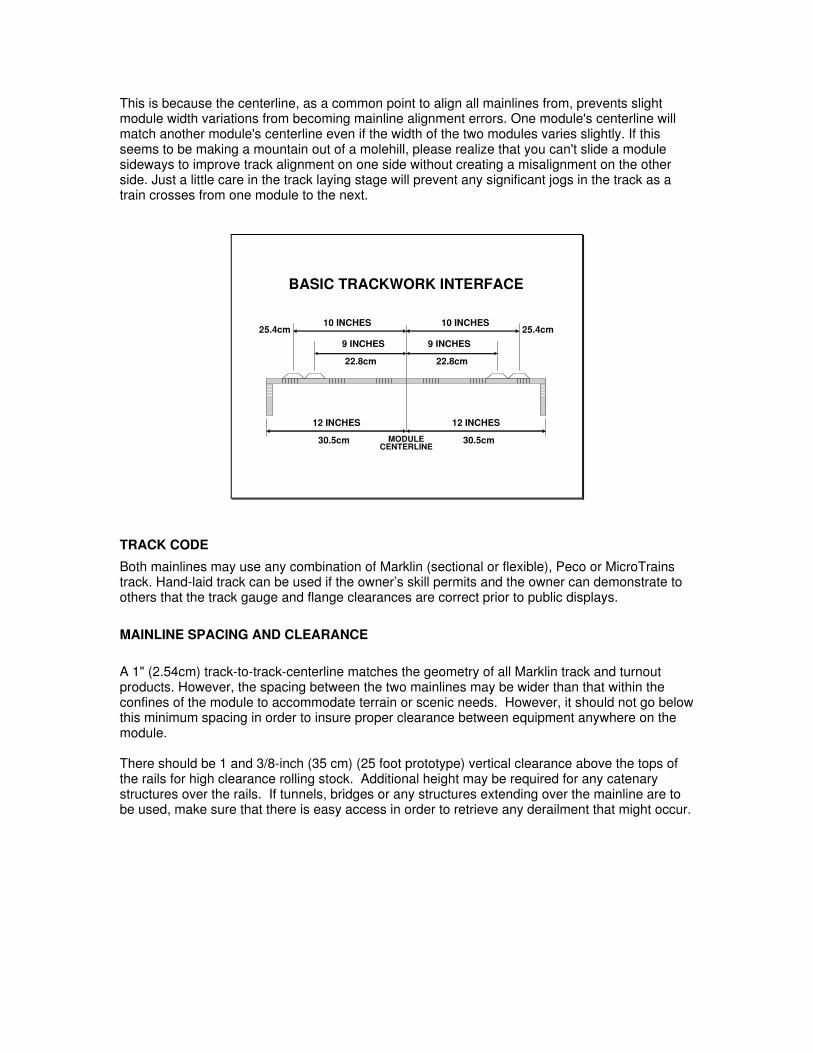
To position the mainlines at each end of a module, you first find the center of the 2 foot (61cm)wide interface, then measure out both directions 9 inches (22.8cm) and 10 inches (25.4cm)inches from the center line. This should leave approximately 2 inches (5cm) from the center of theOuter Track to the side of the module – an important safety distance in the event of a derailment.If you are using Marklin track products, this 1 inch (2.54 cm) spacing of the mainline tracks isrequired by the geometry of their turnouts.
PLEASE RESIST THE TEMPTATION to measure 2" (5cm) and 3" (7.6cm) from the outside edgeof the module inward to locate the track centerlines. We have found the chance for error inalignment of mainlines from one module to another is greatly reduced by measuring out from thecenterline of the module.
This is because the centerline, as a common point to align all mainlines from, prevents slightmodule width variations from becoming mainline alignment errors. One module's centerline willmatch another module's centerline even if the width of the two modules varies slightly. If thisseems to be making a mountain out of a molehill, please realize that you can't slide a modulesideways to improve track alignment on one side without creating a misalignment on the otherside. Just a little care in the track laying stage will prevent any significant jogs in the track as atrain crosses from one module to the next.
BASIC TRACKWORK INTERFACE
10 INCHES 10 INCHES
9 INCHES 9 INCHES
12 INCHES 12 INCHES
MODULECENTERLINE
30.5cm 30.5cm
22.8cm 22.8cm
25.4cm 25.4cm
TRACK CODE
Both mainlines may use any combination of Marklin (sectional or flexible), Peco or MicroTrainstrack. Hand-laid track can be used if the owner’s skill permits and the owner can demonstrate toothers that the track gauge and flange clearances are correct prior to public displays.
MAINLINE SPACING AND CLEARANCE
A 1" (2.54cm) track-to-track-centerline matches the geometry of all Marklin track and turnoutproducts. However, the spacing between the two mainlines may be wider than that within theconfines of the module to accommodate terrain or scenic needs. However, it should not go belowthis minimum spacing in order to insure proper clearance between equipment anywhere on themodule.
There should be 1 and 3/8-inch (35 cm) (25 foot prototype) vertical clearance above the tops ofthe rails for high clearance rolling stock. Additional height may be required for any catenarystructures over the rails. If tunnels, bridges or any structures extending over the mainline are tobe used, make sure that there is easy access in order to retrieve any derailment that might occur.
TRACK SETBACK ON MODULES
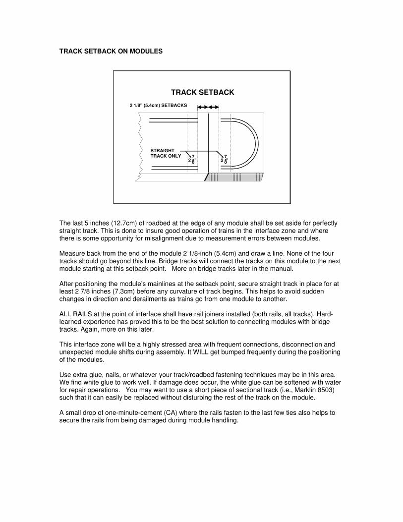
TRACK SETBACK
2 " 2 "
STRAIGHTTRACK ONLY
2 1/8" (5.4cm) SETBACKS
7-87-8
The last 5 inches (12.7cm) of roadbed at the edge of any module shall be set aside for perfectlystraight track. This is done to insure good operation of trains in the interface zone and wherethere is some opportunity for misalignment due to measurement errors between modules.
Measure back from the end of the module 2 1/8-inch (5.4cm) and draw a line. None of the fourtracks should go beyond this line. Bridge tracks will connect the tracks on this module to the nextmodule starting at this setback point. More on bridge tracks later in the manual.
After positioning the module’s mainlines at the setback point, secure straight track in place for atleast 2 7/8 inches (7.3cm) before any curvature of track begins. This helps to avoid suddenchanges in direction and derailments as trains go from one module to another.
ALL RAILS at the point of interface shall have rail joiners installed (both rails, all tracks). Hard-learned experience has proved this to be the best solution to connecting modules with bridgetracks. Again, more on this later.
This interface zone will be a highly stressed area with frequent connections, disconnection andunexpected module shifts during assembly. It WILL get bumped frequently during the positioningof the modules.
Use extra glue, nails, or whatever your track/roadbed fastening techniques may be in this area.We find white glue to work well. If damage does occur, the white glue can be softened with waterfor repair operations. You may want to use a short piece of sectional track (i.e., Marklin 8503)such that it can easily be replaced without disturbing the rest of the track on the module.
A small drop of one-minute-cement (CA) where the rails fasten to the last few ties also helps tosecure the rails from being damaged during module handling.
MAINLINE RADIUS
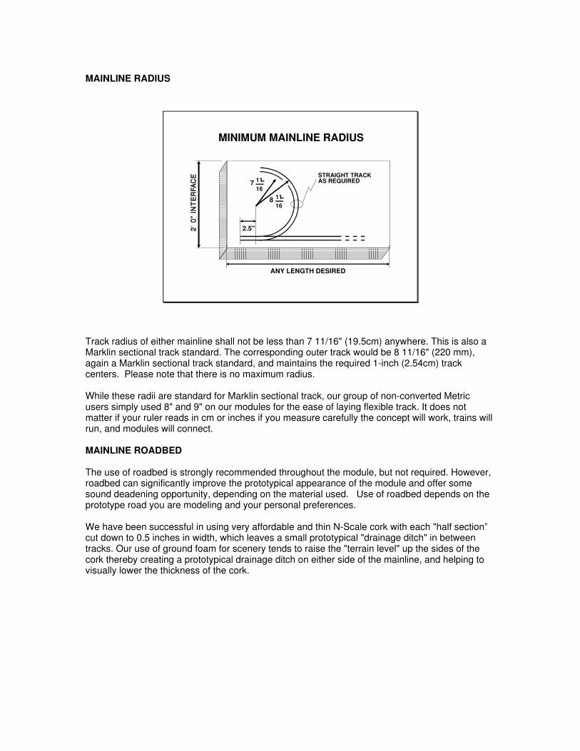
MINIMUM MAINLINE RADIUS
ANY LENGTH DESIRED
7 "1116
8 "1116
2.5"
STRAIGHT TRACKAS REQUIRED
Track radius of either mainline shall not be less than 7 11/16" (19.5cm) anywhere. This is also aMarklin sectional track standard. The corresponding outer track would be 8 11/16" (220 mm),again a Marklin sectional track standard, and maintains the required 1-inch (2.54cm) trackcenters. Please note that there is no maximum radius.
While these radii are standard for Marklin sectional track, our group of non-converted Metricusers simply used 8" and 9" on our modules for the ease of laying flexible track. It does notmatter if your ruler reads in cm or inches if you measure carefully the concept will work, trains willrun, and modules will connect.
MAINLINE ROADBED
The use of roadbed is strongly recommended throughout the module, but not required. However,roadbed can significantly improve the prototypical appearance of the module and offer somesound deadening opportunity, depending on the material used. Use of roadbed depends on theprototype road you are modeling and your personal preferences.
We have been successful in using very affordable and thin N-Scale cork with each "half section”cut down to 0.5 inches in width, which leaves a small prototypical "drainage ditch" in betweentracks. Our use of ground foam for scenery tends to raise the "terrain level" up the sides of thecork thereby creating a prototypical drainage ditch on either side of the mainline, and helping tovisually lower the thickness of the cork.
MAINLINE TURNOUTS
Mainline turnouts are strongly encouraged, both manual and remote. Remote control turnoutsmust have some method of manual operation if electrical circuits fail, or fail in the "through"direction. Marklin turnouts in good operating order are recommended.
If hand laid turnouts are used, they shall be restricted to the "straight" direction on the mainline,unless the module owner has demonstrated the operation, proper gauge and that other geometryare correct prior to public displays.
MAINLINE CROSSOVERS
Crossovers (Back to back turnouts) made with standard turnouts are allowed, and evenencouraged. Marklin crossovers in good operating order are recommended. Hand laid turnoutsare allowed, subject to the owner's demonstration of operation, gauge and other track geometryat shows are correct prior to public displays.
Mainline "X" Crossovers
Are allowed on mainlines, but strongly NOT recommended. In additional to serious electricalpower considerations, 11-degree "X" crossovers seem to be difficult to maintain in properoperation over time. Trains may "bounce" going over them, even if they do not derail. There is notime at shows to be adjusting them. Any use of "X" crossovers must have the prior approval of allother module owners before module assembly begins. Modules with poorly operating crossoverswill be removed from the layout immediately.
Mainline Double Slip Switches
Are NOT allowed. In additional to serious electrical power considerations, double slip switchesseem to be difficult to maintain in proper operation over time. Trains may "bounce" going overthem, even if they do not derail. There is no time at shows to be adjusting them.
MAINLINE GRADES
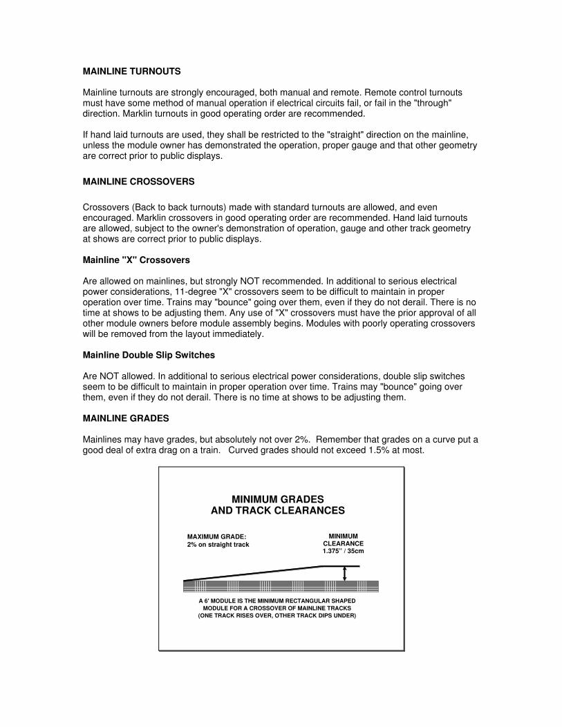
Mainlines may have grades, but absolutely not over 2%. Remember that grades on a curve put agood deal of extra drag on a train. Curved grades should not exceed 1.5% at most.
MINIMUM GRADES
MAXIMUM GRADE: 2% on straight track
MINIMUMCLEARANCE1.375” / 35cm
A 6' MODULE IS THE MINIMUM RECTANGULAR SHAPEDMODULE FOR A CROSSOVER OF MAINLINE TRACKS
AND TRACK CLEARANCES
(ONE TRACK RISES OVER, OTHER TRACK DIPS UNDER)
Our purpose is to run trains of near prototypical length. Grades of greater than 2% severelyimpacts the number of cars that can negotiate the layout with most unmodified Z-Scalelocomotives (no extra internal weight added). Slight grades may make the layout moreinteresting, but can shorten train lengths to near nothing. Test your proposed grade and trackplan with loose track on an inclined surface before committing your ideas to a module.
SOLDERING OF RAILS
While we normally solder all rail connections, and solder track power feeder wires at these samepoints, it is clearly understood that many modelers do not possess the skills to solder track orperform some electrical wiring issues.
Any method of positive, reliable, long-term mechanical and electrical connections to the track thatthe owner is capable of is acceptable. However, if non-solder connections are used, a fullelectrical checkout and repair(s) of the module by the owner is strongly recommended before theday of group assembly time. Rail joiners have a bad habit of electrically failing without notice.
Modules which do not fully function (mechanical or electrical) at assembly time should be takenout of the layout and set aside for maintenance on another day.
SCENERY TRACKS
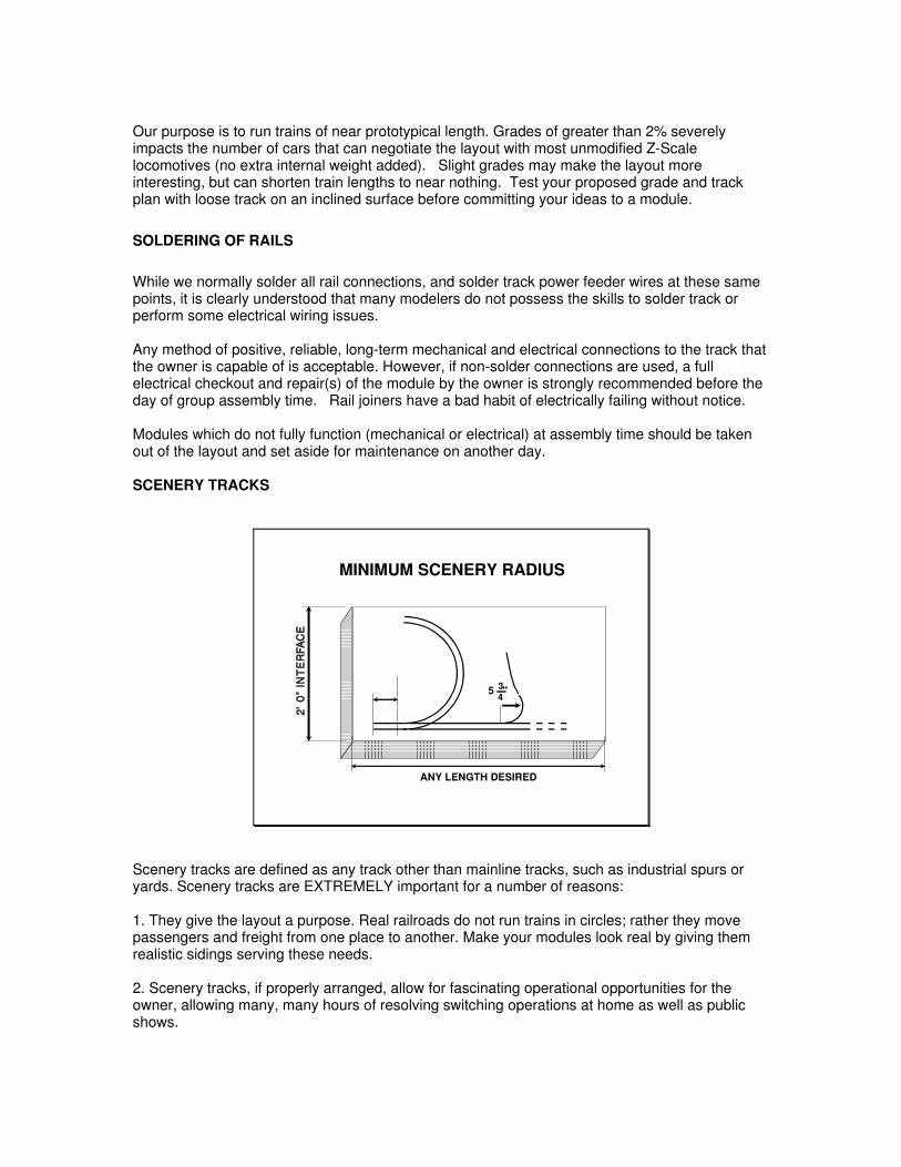
MINIMUM SCENERY RADIUS
ANY LENGTH DESIRED
5 "34
Scenery tracks are defined as any track other than mainline tracks, such as industrial spurs oryards. Scenery tracks are EXTREMELY important for a number of reasons:
1. They give the layout a purpose. Real railroads do not run trains in circles; rather they movepassengers and freight from one place to another. Make your modules look real by giving themrealistic sidings serving these needs.
2. Scenery tracks, if properly arranged, allow for fascinating operational opportunities for theowner, allowing many, many hours of resolving switching operations at home as well as publicshows.

While many viewers are attracted to the continuously running of trains on the mainlines, theattention of many viewers can be further captured by switching operations on the scenic tracks,regardless of the coupler system used (Marklin or MT).
SCENERY TRACK
Scenery tracks may be any type of commercial track that is available. They may also be handlaid, if so inclined, without prior inspection or approval of other module owners.
SCENERY RADIUS
There are no radius restrictions on scenery tracks. However radii smaller than Marklin's smallestsectional track is not recommended (5 3/4 / 145mm).
SCENERY GRADES
There are no grade restrictions on scenery tracks.
SCENERY TURNOUTS
Turnouts can be any type of commercial or hand laid, and may have any radius.
SCENERY ROADBED
There are no restrictions or requirements for roadbed.
SCENERY ELECTRICAL
While there are no electrical requirements for scenery tracks, owners are STRONGLYencouraged to power these tracks for operational reasons, previously stated.
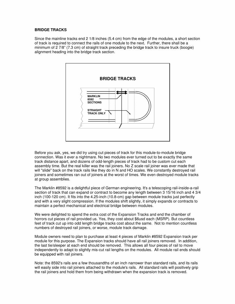
BRIDGE TRACKS
Since the mainline tracks end 2 1/8 inches (5.4 cm) from the edge of the modules, a short sectionof track is required to connect the rails of one module to the next. Further, there shall be aminimum of 2 7/8” (7.3 cm) of straight track preceding the bridge track to insure truck (boogie)alignment heading into the bridge track section.
BRIDGE TRACKS
MARKLIN8592SECTIONS
STRAIGHTTRACK ONLY
Before you ask, yes, we did try using cut pieces of track for this module-to-module bridgeconnection. Was it ever a nightmare. No two modules ever turned out to be exactly the sametrack distance apart, and dozens of odd-length pieces of track had to be custom cut eachassembly time. But the real killer was the rail joiners. No Z scale rail joiner was ever made thatwill "slide" back on the track rails like they do in N and HO scales. We constantly destroyed railjoiners and sometimes ran out of joiners at the worst of times. We even destroyed module tracksat group assemblies.
The Marklin #8592 is a delightful piece of German engineering. It's a telescoping rail-inside-a-railsection of track that can expand or contract to become any length between 3 15/16 inch and 4 3/4inch (100-120 cm). It fits into the 4.25-inch (10.8-cm) gap between module tracks just perfectlyand with a very slight compression. If the modules shift slightly, it simply expands or contracts tomaintain a perfect mechanical and electrical bridge between modules.
We were delighted to spend the extra cost of the Expansion Tracks and end the chamber ofhorrors cut pieces of rail provided us. Yes, they cost about $6usd each (MSRP). But countlessfeet of track cut up into odd length bridge tracks cost about the same. Not to mention countlessnumbers of destroyed rail joiners, or worse, module track damage.
Module owners need to plan to purchase at least 4 pieces of Marklin #8592 Expansion track permodule for this purpose. The Expansion tracks should have all rail joiners removed. In addition,the last tie/sleeper at each end should be removed. This allows all four pieces of rail to moveindependently to adapt to slightly mis-cut rail lengths on the modules. All module rail ends shouldbe equipped with rail joiners.
Note: the 8592's rails are a few thousandths of an inch narrower than standard rails, and its railswill easily side into rail joiners attached to the module's rails. All standard rails will positively gripthe rail joiners and hold them from being withdrawn when the expansion track is removed.
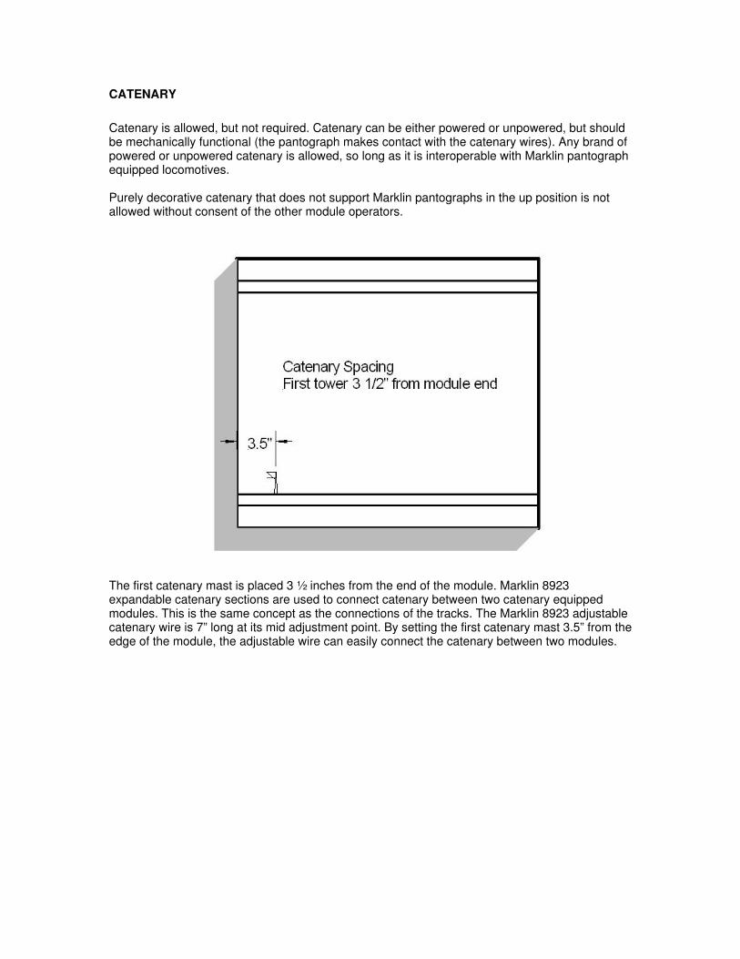
CATENARY
Catenary is allowed, but not required. Catenary can be either powered or unpowered, but shouldbe mechanically functional (the pantograph makes contact with the catenary wires). Any brand ofpowered or unpowered catenary is allowed, so long as it is interoperable with Marklin pantographequipped locomotives.
Purely decorative catenary that does not support Marklin pantographs in the up position is notallowed without consent of the other module operators.
The first catenary mast is placed 3 ½ inches from the end of the module. Marklin 8923expandable catenary sections are used to connect catenary between two catenary equippedmodules. This is the same concept as the connections of the tracks. The Marklin 8923 adjustablecatenary wire is 7” long at its mid adjustment point. By setting the first catenary mast 3.5” from theedge of the module, the adjustable wire can easily connect the catenary between two modules.
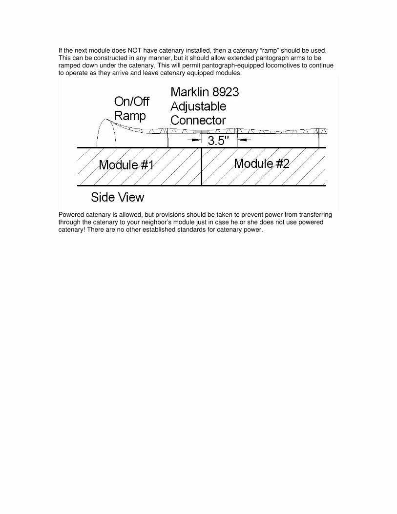
If the next module does NOT have catenary installed, then a catenary “ramp” should be used.This can be constructed in any manner, but it should allow extended pantograph arms to beramped down under the catenary. This will permit pantograph-equipped locomotives to continueto operate as they arrive and leave catenary equipped modules.
Powered catenary is allowed, but provisions should be taken to prevent power from transferringthrough the catenary to your neighbor’s module just in case he or she does not use poweredcatenary! There are no other established standards for catenary power.

BASIC WOOD WORKING
BASIC MODULE CONSTRUCTION
1"x4"SIDES &
ENDS
24"
APPX. 4"
Z-Bend Track modules are no different in construction than any other modular standard. Asimple, lightweight and strong frame is key to any module, no matter is length or shape. Pine 1x4lumber is quite sufficient our experience has shown. Please note that the sidepieces go theentire length of the module and the end pieces go between them. This helps to have anattractive, continuous and smooth side to the module, which is what the public sees.
MODULE SUPPORT DETAILS
3" FROM TOP OFCORK ROADBED
3/8" HOLE 7" EITHERSIDE OF CENTERLINE
End modules present a special case. Since they are typically without legs, a simple "C" clamp isnot sufficient to maintain the module's alignment at the end of a row of modules. We have foundthat people (even ourselves) tend to use the end module as an armrest, which can result in the1x4 lumber on the end shattering under the "C" clamp. We drill 3/8" (~1 cm) holes in the ends ofALL modules for the purpose of using 1/4" (~6.4mm) bolt and wingnut hardware to fasten theballoons on the end of ANY module. These extra bolts stabilize the module from slipping downon one side of another.
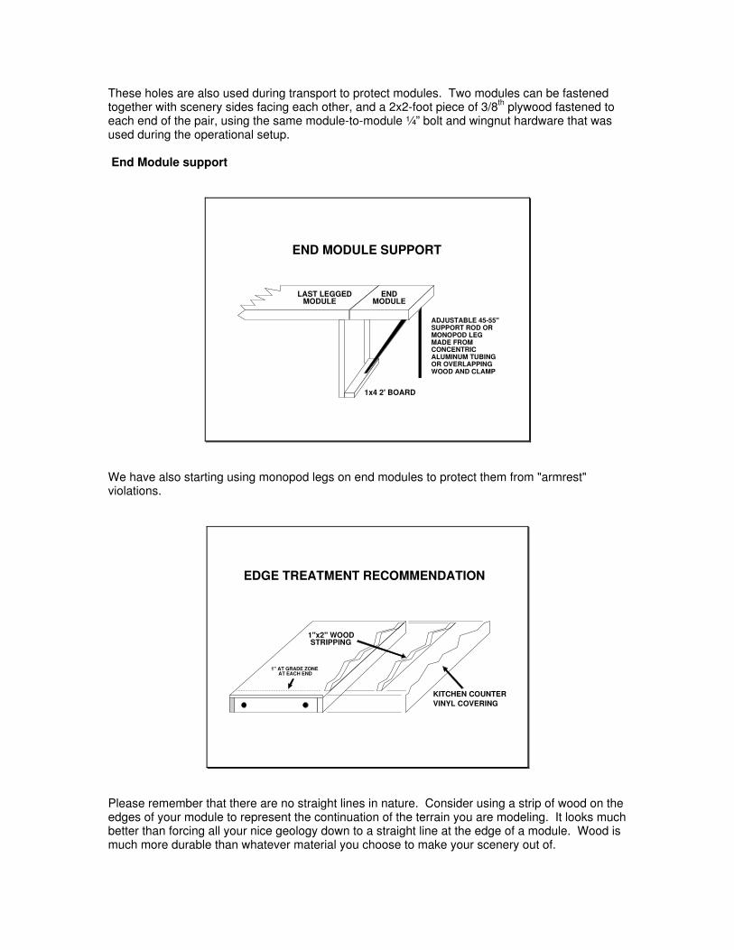
These holes are also used during transport to protect modules. Two modules can be fastenedtogether with scenery sides facing each other, and a 2x2-foot piece of 3/8th plywood fastened toeach end of the pair, using the same module-to-module ¼” bolt and wingnut hardware that wasused during the operational setup.
End Module support
END MODULE SUPPORT
LAST LEGGEDMODULE
ENDMODULE
1x4 2' BOARD
ADJUSTABLE 45-55"SUPPORT ROD ORMONOPOD LEGMADE FROMCONCENTRICALUMINUM TUBINGOR OVERLAPPINGWOOD AND CLAMP
We have also starting using monopod legs on end modules to protect them from "armrest"violations.
EDGE TREATMENT RECOMMENDATION
KITCHEN COUNTERVINYL COVERING
1"x2" WOODSTRIPPING
1" AT GRADE ZONEAT EACH END
Please remember that there are no straight lines in nature. Consider using a strip of wood on theedges of your module to represent the continuation of the terrain you are modeling. It looks muchbetter than forcing all your nice geology down to a straight line at the edge of a module. Wood ismuch more durable than whatever material you choose to make your scenery out of.

Lastly, we tend to use thin wood-grain vinyl countertop material to cover both the 1x4 lumber andthe thin strip of wood terrain material on the sides that visitors will see. It cuts with a sharp knifeor scissors and glues on nicely with standard contact cements. In addition to the visual benefit, itprovides for a scratch free durable side on your module at shows. Although we treat modulesvery tenderly, inevitably, a module will be slid along a rough concrete floor, sooner or later.Painted edges scratch badly during transport while durable counter top material does not.
Kitchen replacement countertop material is available in a wide range of solid colors and woodgrains to suit your color preferences. It cuts with scissors or a sharp knife and can be filed orsanded to irregular shapes on the side edge of your module.
Drapes:
VELCRO STRIP FOR DRAPERY
BELOW TOP OF RAILS
3/4" (2cm) VELCROHOOK SIDE ON MODULELOOP (FUZZY) SIDE ON FABRIC
VELCRO STARTS 2 3/4" (7cm)
While a layout may be sceniced to perfection, looking at it standing on a bunch of exposed legsand toolboxes and crates stacked underneath will not help the overall visual image to viewers. Itreally looks nice to provide for some form of drapery around the modules to hide all that. In orderto make all the drapes across (and mate with) all modules, a 3/4 inch (2cm) Velcro Hook tapeshould be fastened across the entire length of a modules side. The “hook” component of theVelcro tape should be fastened 2 3/4 inches (7cm) below the height of the rails. The loop (fuzzy)side of the Velcro tape should be fastened to the draperies.
ELECTRICAL (BACKGROUND)
For transmitting power from module to module, we settled on the DB-25 series connector that iscommon available throughout the world. It’s the same gold plated connector type that you find onthe back of Personal Computers (printer port, serial port, video, etc.). Not only is the connectorunder one dollar USD, but it is extremely reliable, as any PC owner will acknowledge. It canaccept multiconductor 26-awg wiring as well as 18-awg lamp cord, sometimes called "zip cord"for the power circuits. The resulting bundle of wiring is small, even with the added functions.
The power rating on DB series pins is 7 amps per pin for machined pins, and around 1 amp onquality crimp pins. We use three pins together to insure sufficient current capacity not only fornormal operations, but also for catastrophic short conditions. The connector will still functionnormally if a single pin is accidentally broken during transport.
This solution has withstood the test of time in the field for six years, and the skills of a wide varietyof module builders. Because of its wide spread use, crimp type connectors and crimp tools arecommonly available at computer outlets for those that do not wish to solder wires.
When considering a wiring plan that can support 100 feet of modules, special consideration waspaid to voltage drops in the backbone cable. No one wants to have to constantly twist a throttleback and forth to compensate for "slow trains" at the far end and "fast trains" close to the throttle.Our planning was to have no more than a 10% voltage drop 100 feet from the throttle with threelocomotives pulling a 100-car train. Our super large layouts at the National Train Shows haveproven that design goal has been achieved.
Additionally, when layouts become very large, the throttle operator may not be in visual contactwith their train for periods of time. There are special problems the Z-Bend Track wiring planconsiders:
1. The Z-Bend Track wiring is both DC and DCC compliant. Users can even switchback and forth between the two power sources, or have one mainline on DC and theother on DCC. It offers the owner the flexibility to run one mode at home and anotherat shows.
2. Since derailments in Z are not uncommon, we felt it was important that the wiringcarry sufficient current to insure a power pack's circuit breaker would trip whenlocomotives derail, and before the locomotive's trucks melt down from excessiveshort circuit currents (yes, that can happen at turnouts). This is especially true whenworking from DCC power sources.
3. Crowd noise frequently prevents effective communications between train operatorsand assisting observers. When a multi-engine consist derails, frequently thelocomotives still on the track work to push the derailed locomotive in the lead off theedge of the table. We have added a circuit that enables simple pushbuttons to beplaced around the layout which, when pressed, will completely shut down power to alltracks on the layout. If it's YOUR locomotive that's headed for the edge of themodule, you will appreciate this safety feature much more.
4. In the original wiring plan, several non-power conductors (pins 22-25) were set asidefor wired communications circuits (i.e., headsets) to overcome crowd noise whenoperating the layout. However, the extremely affordable 2-way personal radios (i.e.,FRS/GMRS) made these considerations unnecessary. These circuits are no longerrequired by the standard.
However, these lines are now set aside for “user defined” conductors for electricalservice between a given builder’s module set. If you use these circuits, you must

provide some method of disconnecting (or isolating) these conductors fromother modules you may connect up to. Remember that 24-awg wiring and a singleDB-25 pin do not carry much current either. In-line glass fuses are recommended inthese circuit paths.

ELECTRICAL SPECIFICATIONS
Each half of the module is electrically totally independent from the other half. Each half of themodule has a cable that furnishes a number of power connections to that half of the module,while other circuits just pass through. All power circuit and accessory power circuit wiring in thebackbone must be at least 18 awg. Non-power circuits may be 24 awg.
BASIC WIRING CONCEPT
DC POWER FEEDOUTSIDE TRACK POWERINSIDE TRACK POWEREMERGENCY SHUTDOWN CIRCUITOPTIONAL USER DEFINED CIRCUITS
DC POWER FEEDOUTSIDE TRACK POWERINSIDE TRACK POWEREMERGENCY SHUTDOWN CIRCUITOPTIONAL USER DEFINED CIRCUITS
EACH MODULE IS ELECTRICALLY SPLIT IN HALF
DB25
DB25 DB25
DB25
FEMALE
MALEFEMALE
MALE
(TOP VIEW)
Each half of the module has a cable furnishes a number of power connections to the module half,while other circuits just pass through. In addition to track power, each module is furnished with ascenery power circuit for lights and animation uses (up to 1/3 amp per module). If you usescenery power, you are expected to provide a glass fuse (not a mechanical circuit breaker) toinsure that if you develop a short circuit, the fuse will blow and the rest of the modules will not beaffected. In addition, some method (i.e., an on/off switch) should be provided to disable thescenery power should an electrical malfunction occur in the module during a show.
DO NOT USE pre-made computer cables (printers, serial modems, etc.). While veryinexpensive, they use extremely tiny wiring, which is absolutely not sufficient for power conductorservice over great distances. Some pre-made computer cables have special internal wiring thatwill short out other Z-Bend Track modules with correct "standard" wiring.

DB-25 CONNECTORS
This is what a DB-25 connector looks like when you start to add wires to it. Note the method ofcounting pins when viewed from the back of the connector (solder side).
DB25 CONNECTOR PIN NUMBERING
1 2 3 4 5 6 7 8 9 10 11 12 13
14 15 16 17 18 19 20 21 22 23 24 25
13 12 11 10 9 8 7 6 5 4 3 2 1
25 24 23 22 21 20 19 18 17 16 15 14
DB 25 - SOLDER SIDE - FEMALE
DB 25 - SOLDER SIDE - MALE
*POWERING UP MODULES
Since all modules have the same identical wiring plan, there must be a provision for applyingpower to modules. This is done without modification to any module by simply by plugging in anadapter in-between any two modules. In the illustration below, one of the mainline tracks ispowered across all modules by a single throttle feed at an adapter that is inserted between thecables of two modules. The throttle would work equally well if it was moved anywhere around thelayout shown.
BASIC CONNECTED LAYOUT
CONTROLS TRACK
EXAMPLE: OPERATOR CONTROLS ENTIRE OUTER TRACK
By using insulated rail joiners on one end of bridge tracks and a special one-way power feedadapters, you can electrically break up the layout into several electrical "blocks" each with its own

throttle and operator. One operator can "hand off" a train to another operator's control as itpasses over insulated rail joiners and begins taking power from the new operator's power pack.Think for a second, isn't this exactly how prototype trains work, with the train passing from onecontrol section to another and with coordination between from both dispatchers? Why not hasfun with this in models as well?
BLOCK CONTROL OF LAYOUT
CONTROLSBLOCK
CONTROLSBLOCK
CONTROLSBLOCK
EXAMPLE: OUTER TRACK IS BROKEN INTO BLOCKSWITH THE USE OF DIRECTIONAL POWER ADAPTORS
(INNER TRACK IS INDEPENDENT OF THIS BLOCKING)
DETAILS OF WIRING
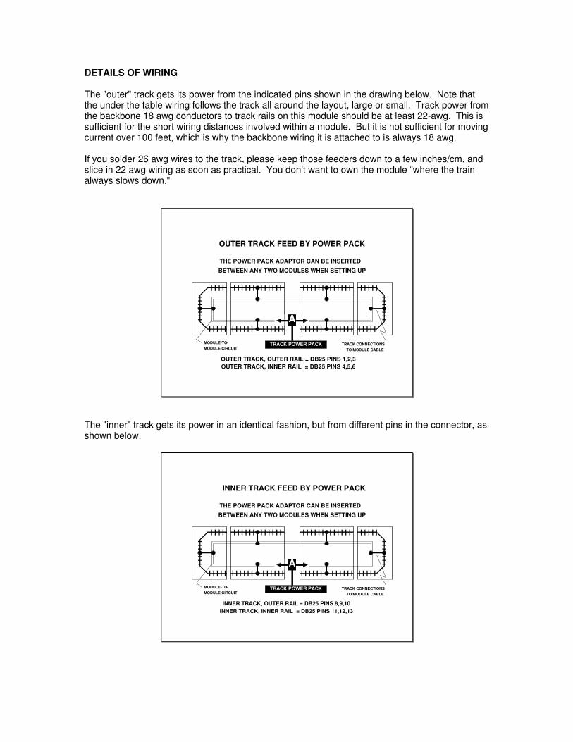
The "outer" track gets its power from the indicated pins shown in the drawing below. Note thatthe under the table wiring follows the track all around the layout, large or small. Track power fromthe backbone 18 awg conductors to track rails on this module should be at least 22-awg. This issufficient for the short wiring distances involved within a module. But it is not sufficient for movingcurrent over 100 feet, which is why the backbone wiring it is attached to is always 18 awg.
If you solder 26 awg wires to the track, please keep those feeders down to a few inches/cm, andslice in 22 awg wiring as soon as practical. You don't want to own the module “where the trainalways slows down."
TRACK POWER PACK
OUTER TRACK FEED BY POWER PACK
OUTER TRACK, OUTER RAIL = DB25 PINS 1,2,3
THE POWER PACK ADAPTOR CAN BE INSERTED
BETWEEN ANY TWO MODULES WHEN SETTING UP
TRACK CONNECTIONSTO MODULE CABLE
OUTER TRACK, INNER RAIL = DB25 PINS 4,5,6
A
MODULE-TO-MODULE CIRCUIT
The "inner" track gets its power in an identical fashion, but from different pins in the connector, asshown below.
TRACK POWER PACK
THE POWER PACK ADAPTOR CAN BE INSERTED
BETWEEN ANY TWO MODULES WHEN SETTING UP
TRACK CONNECTIONSTO MODULE CABLE
A
MODULE-TO-MODULE CIRCUIT
INNER TRACK FEED BY POWER PACK
INNER TRACK, OUTER RAIL = DB25 PINS 8,9,10INNER TRACK, INNER RAIL = DB25 PINS 11,12,13
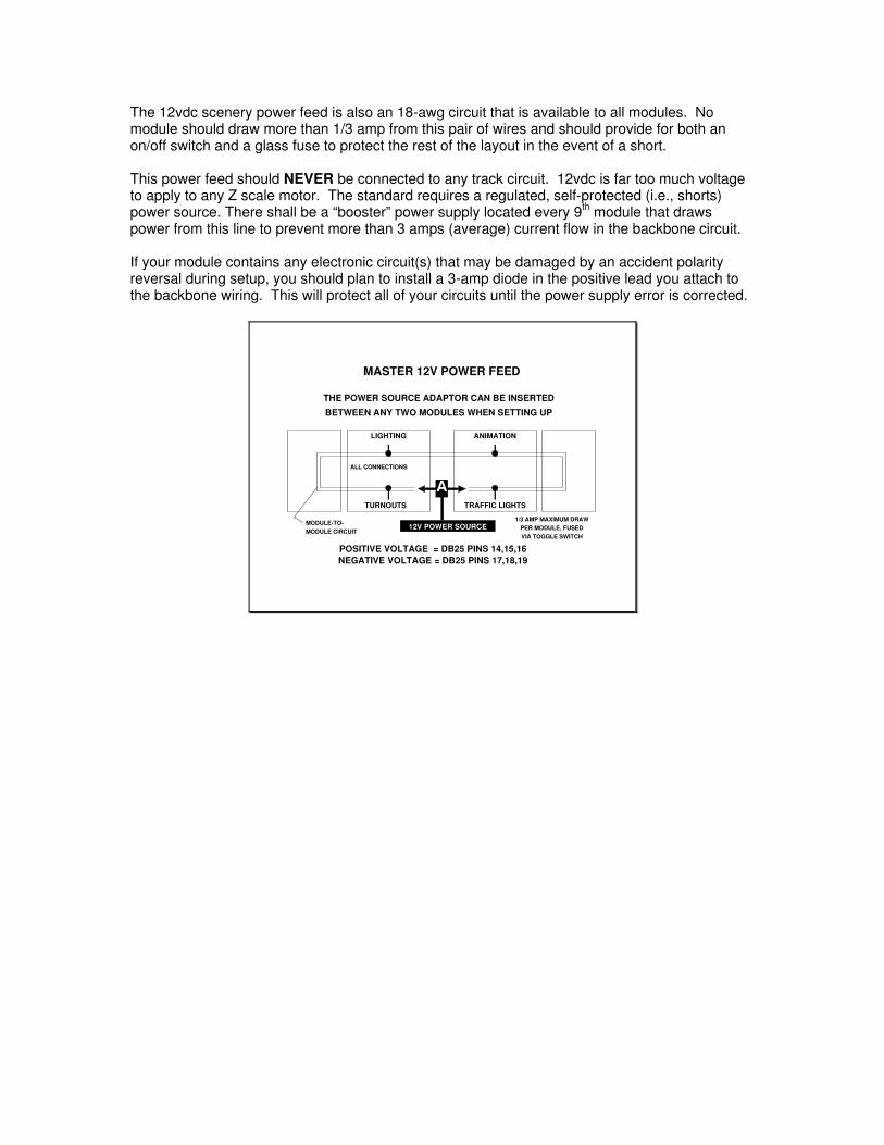
The 12vdc scenery power feed is also an 18-awg circuit that is available to all modules. Nomodule should draw more than 1/3 amp from this pair of wires and should provide for both anon/off switch and a glass fuse to protect the rest of the layout in the event of a short.
This power feed should NEVER be connected to any track circuit. 12vdc is far too much voltageto apply to any Z scale motor. The standard requires a regulated, self-protected (i.e., shorts)power source. There shall be a “booster” power supply located every 9th module that drawspower from this line to prevent more than 3 amps (average) current flow in the backbone circuit.
If your module contains any electronic circuit(s) that may be damaged by an accident polarityreversal during setup, you should plan to install a 3-amp diode in the positive lead you attach tothe backbone wiring. This will protect all of your circuits until the power supply error is corrected.
MASTER 12V POWER FEED
A
12V POWER SOURCE
POSITIVE VOLTAGE = DB25 PINS 14,15,16
THE POWER SOURCE ADAPTOR CAN BE INSERTED
BETWEEN ANY TWO MODULES WHEN SETTING UP
MODULE-TO- 1/3 AMP MAXIMUM DRAW
MODULE CIRCUIT PER MODULE, FUSED
NEGATIVE VOLTAGE = DB25 PINS 17,18,19
LIGHTING ANIMATION
TURNOUTS TRAFFIC LIGHTS
ALL CONNECTIONS
VIA TOGGLE SWITCH

There are several pass-through circuits in the cable. One is an emergency shut down circuit. Atshows, crowd noise often prevents good communications between operators. In order to providean emergency shutdown function for trains from various points around the layout, a low voltage isapplied between these two leads. Push button switches are periodically added between modulesby way of adapters between modules. If any of the push buttons are pressed, the closure acrossthese wires will trigger the complete shutdown of all track power supplies. Power will be restoredby a central push button. Wiring should be 22-awg wire. The detector circuit will be published inan Appendix to this manual.
EMERGENCY OFF & PUSH BUTTONS
EMERGENCY TRACK POWER SHUTDOWN BY A SWITCH
THE OPTIONAL POWER SHUTDOWN CIRCUIT AND "N" NUMBEROF PUSH BUTTONS CAN CONNECTED DURING SETUP
CLOSURE BETWEEN DB25 PINS 20 AND 21, ANYWHERE
A
PWR. SHUTOFF CKT.MODULE-TO-MODULE CIRCUIT
A
PUSH BUTTON(S)
There are also 4 wires reserved for user defined circuits (pins 22, 23, 24 and 25). If you providewiring on these pins, you must provide for some method of isolating your wiring from adjacentmodules (i.e., adapter, switch, etc.) which may use these conductors for an entirely differentfunction.
As example, Rob Allbritton has utilized these extra circuits for enhanced DCC train detectionwithin his set of Gotthard Line modules. His uses are shown below:
Pin# DCC Use
7 DCC Ground20 Loop to Pin 2121 Loop to Pin 2022 Digitrax BDL-16 Power (A) 12VAC23 Digitrax BDL-16 Power (B) 12VAC24 DCC Signal (A) 12VAC25 DCC Signal (B) 12VAC
Pin 7 and 22 through 25 are used for specific DCC purposes:DCC Ground and BDL-16 Power are needed for Digitrax electronic train detectionDCC Signal is a “cleaner” way for the turnout DCC decoders to receive instructions
If a DCC module is plugged into an analog module by mistake, thenlooping Pins 20 and 21 will trigger the automatic shutdown of theanalog modules for their own protection. Normally, a DCC to Analogconverter adapter (DB25) will separate out pins 7 and 20 through 25.
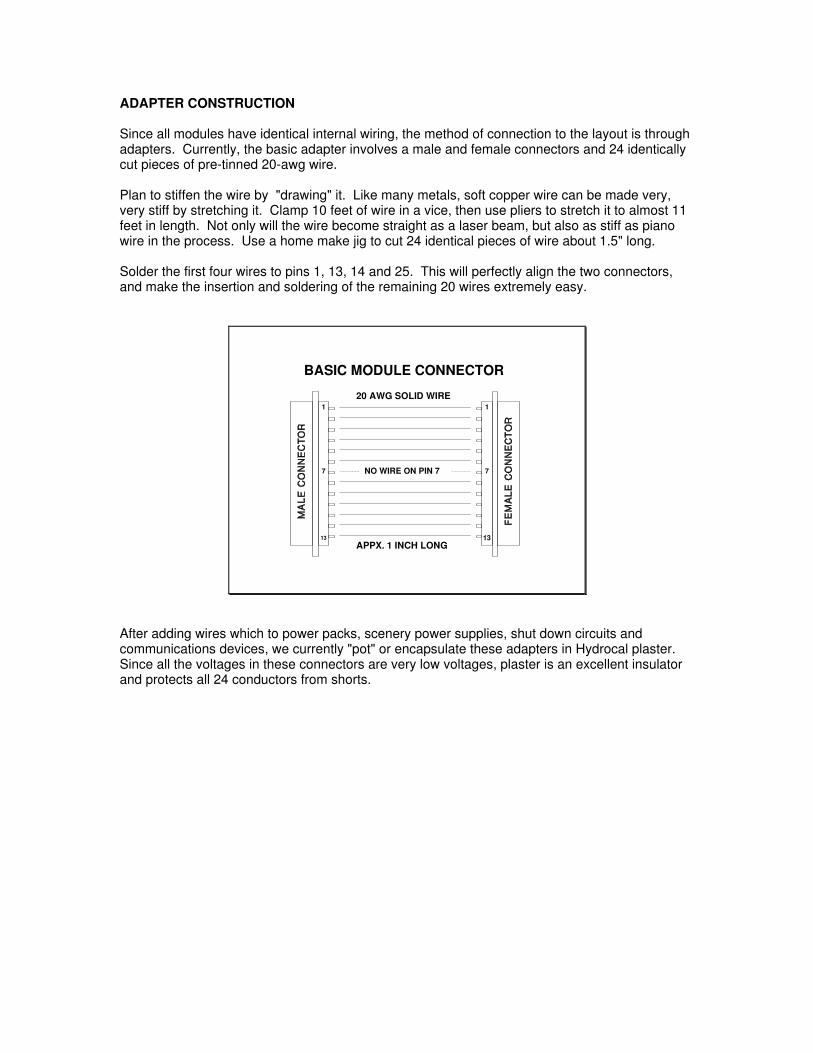
ADAPTER CONSTRUCTION
Since all modules have identical internal wiring, the method of connection to the layout is throughadapters. Currently, the basic adapter involves a male and female connectors and 24 identicallycut pieces of pre-tinned 20-awg wire.
Plan to stiffen the wire by "drawing" it. Like many metals, soft copper wire can be made very,very stiff by stretching it. Clamp 10 feet of wire in a vice, then use pliers to stretch it to almost 11feet in length. Not only will the wire become straight as a laser beam, but also as stiff as pianowire in the process. Use a home make jig to cut 24 identical pieces of wire about 1.5" long.
Solder the first four wires to pins 1, 13, 14 and 25. This will perfectly align the two connectors,and make the insertion and soldering of the remaining 20 wires extremely easy.
BASIC MODULE CONNECTOR
20 AWG SOLID WIRE
APPX. 1 INCH LONG
1
13
1
13
77 NO WIRE ON PIN 7
After adding wires which to power packs, scenery power supplies, shut down circuits andcommunications devices, we currently "pot" or encapsulate these adapters in Hydrocal plaster.Since all the voltages in these connectors are very low voltages, plaster is an excellent insulatorand protects all 24 conductors from shorts.
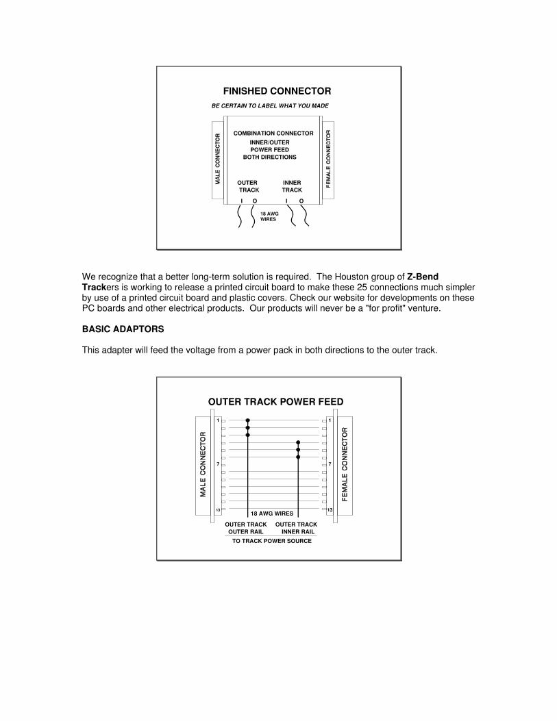
FINISHED CONNECTOR
COMBINATION CONNECTOR
INNER/OUTERPOWER FEED
OUTERTRACK
INNERTRACK
I O I O
BOTH DIRECTIONS
BE CERTAIN TO LABEL WHAT YOU MADE
18 AWGWIRES
We recognize that a better long-term solution is required. The Houston group of Z-BendTrackers is working to release a printed circuit board to make these 25 connections much simplerby use of a printed circuit board and plastic covers. Check our website for developments on thesePC boards and other electrical products. Our products will never be a "for profit" venture.
BASIC ADAPTORS
This adapter will feed the voltage from a power pack in both directions to the outer track.
OUTER TRACK POWER FEED
1
13
1
13
77
OUTER TRACKOUTER RAIL
OUTER TRACKINNER RAIL
TO TRACK POWER SOURCE
18 AWG WIRES

This adapter will feed power from a power pack in both directions to the inner track. Note that theOuter and Inner power packs do not have to be at the same location on the layout. They can belocated between any two modules. This is very helpful when you have a small group of modelersand a large layout with limited operator vision. The two operators could "see" the entire layoutmuch better if their power supply stations are in different locations around the layout.
INNER TRACK POWER FEED
1
13
1
13
77
INNER TRACKOUTER RAIL
INNER TRACKINNER RAIL
TO TRACK POWER SOURCE
18 AWG WIRES
This adapter will feed the power from two power packs to both the Outer and Inner tracks at asingle location.
DOUBLE TRACK FEED CONNECTOR
1
13
1
13
77
OUTER TRACKPOWER PACK
INNER TRACKPOWER PACK
COMBINATION CONNECTOR
18 AWG WIRES
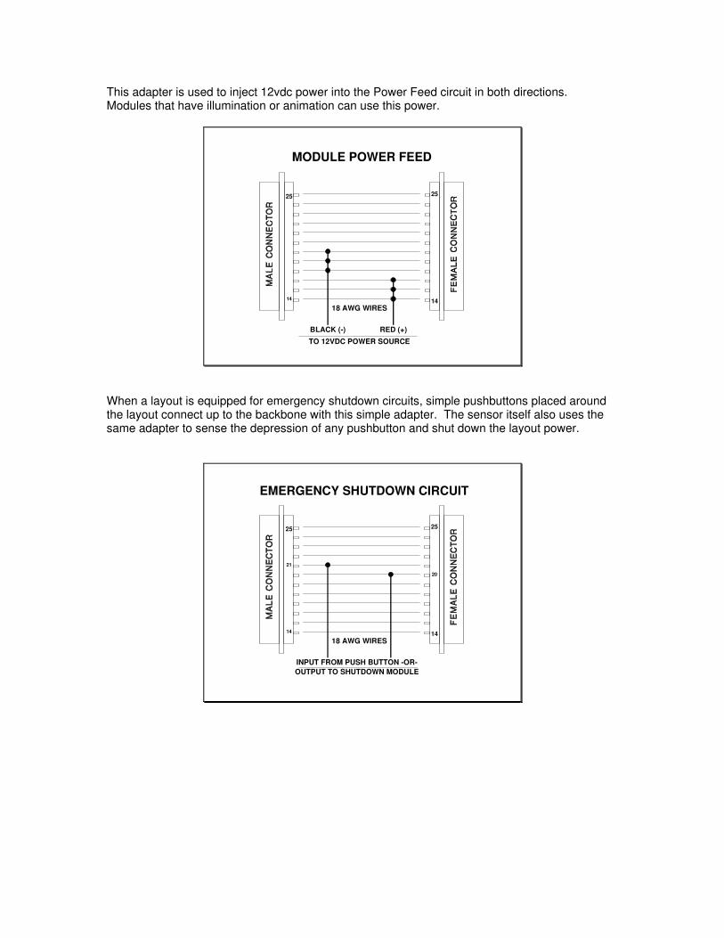
This adapter is used to inject 12vdc power into the Power Feed circuit in both directions.Modules that have illumination or animation can use this power.
MODULE POWER FEED
25
14
25
14
BLACK (-) RED (+)
TO 12VDC POWER SOURCE
18 AWG WIRES
When a layout is equipped for emergency shutdown circuits, simple pushbuttons placed aroundthe layout connect up to the backbone with this simple adapter. The sensor itself also uses thesame adapter to sense the depression of any pushbutton and shut down the layout power.
EMERGENCY SHUTDOWN CIRCUIT
25
14
25
14
INPUT FROM PUSH BUTTON -OR-OUTPUT TO SHUTDOWN MODULE
18 AWG WIRES
21
20
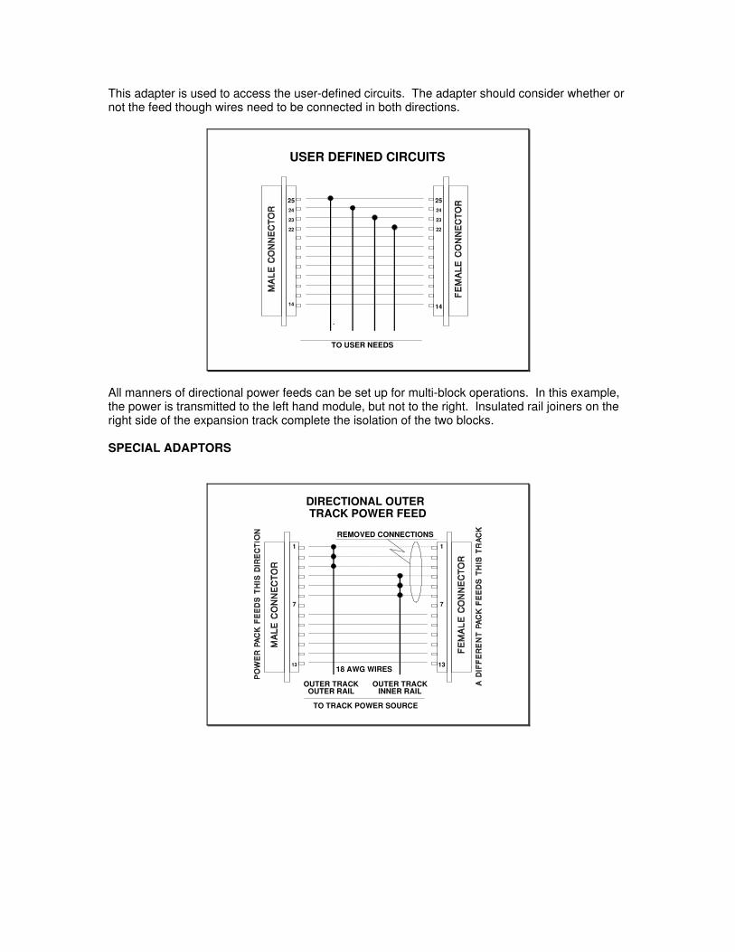
This adapter is used to access the user-defined circuits. The adapter should consider whether ornot the feed though wires need to be connected in both directions.
USER DEFINED CIRCUITS
25
14
25
14
TO USER NEEDS
22
23
24 24
23
22
.
All manners of directional power feeds can be set up for multi-block operations. In this example,the power is transmitted to the left hand module, but not to the right. Insulated rail joiners on theright side of the expansion track complete the isolation of the two blocks.
SPECIAL ADAPTORS
TRACK POWER FEED
1
13
1
13
77
OUTER TRACKOUTER RAIL
OUTER TRACKINNER RAIL
TO TRACK POWER SOURCE
18 AWG WIRES
REMOVED CONNECTIONS
DIRECTIONAL OUTER

DC OPERATIONS
While the source of track power in a home environment is strictly up to the owner, in a groupsetting there will be some sensitivity to power sources due to a very wide range of motive powerand internal train accessories that may be placed on the track. At public shows almost all of theOperations will be in the form of continuous running. Rather than place locomotives, user builtsolid state accessories and exotic motors at unknown compatibility risks with unknown powersources, only pure DC power packs should power the mainlines. Voltages shall not exceed 8volts. Train speeds should be prototypical at all times. All devices including electrostaticgenerators or pulse power should not be applied to the rails. No one wants to accidentallydamage someone’s special lighting circuit or expensive motor.
DCC OPERATIONS
Z-Bend Track fully supports DCC operation. No special wiring is required to the modules forDCC operation. The DCC encoded power is sent to the modules via the standard track powerfeed adapters. From an electrical standpoint, the DCC encoded power is sent into the modulesthe way any other throttle works, but during operating sessions DCC power must be isolatedfrom analog power, unless you enjoy pyrotechnics!
The DCC booster must have short circuit protection. We strongly recommend use of a powermanagement unit, such as a Digitrax PM4. It has superior DCC short circuit protection, and willprovide protection for both locomotives, as well as inadvertent connection between DCC andAnalog powered modules.
The best way to implement DCC in a mixed analog / digital layout is to designate the outer trackas Analog and the inner track as DCC, or vise versa. Another wonderful way to share digital andanalog is to have a special interface module that allows the outer tracks to go through, but loopsthe inner tracks back on themselves:
Analog
Analog
Analog
Analog
Analog
Analog
DCC Digital
DCC Digital
This solution allows some of the modules to have a DCC digital inner track, but allows the outertrack to be available for all through running trains. The Washington and Houston groups did thisat two NMRA National Train Shows with absolutely no problems. The Washington DC modulesalso pass Digitrax Loconet from module to module in a daisy chain fashion using RJ45connectors not covered by this standard. Contact Rob Allbritton at [email protected] formore information if you would like to make your Z-Bend Track modules compatible with theWashington DC modules.

Prior to placement of locomotives and rolling stock on the track, the owner of the DCC equipmentpowering the rails shall advise the equipment owner of the maximum voltage that the DCCequipment will be applying to the rails. The owner of the DCC power source should make allpossible attempts to maintain a track waveform that is reasonable and safe for the widest rangeof decoders, lighting accessories and user built circuits.

APPENDIX 1
Acknowledgment of Intellectual Property:
The concept of Z-Bend Track borrows heavily from the original work of Allen Heimsoth and JimHoover, the creators of N Scale's "Bend Track." With their knowledge and generous support andpermission, Z-Bend Track was born.
Our Z-Bend Track logo reflects the N Scale "Bend Track " logo as a sign of our appreciation.The N Scale "Bend Track" website is an excellent reference, and can be found at the URL:
http://www.alltel.net/~ah50902/
The Z-Bend Track website can be found at:
www.zbendtrack.com
Copyright January 1st, 2004 (first issued: July 1, 2002)
Bill KronenbergerChad BryanJack WithemRob Allbritton