module 4:environmentalchallenges – pulp& …€¢ tier 2: case study applications • tier 3:...
TRANSCRIPT

Program for North American Mobility in Higher Education
Introducing Process Integration for Environmental Control in Engineering Curricula
Module 4: Environmental Challenges –Pulp & Paper Industry
Caroline GaudreaultCreated at:
École Polytechnique de Montréal &Texas A&M University, 2003

2
Purpose of Module X
What is the purpose of this module?
This module is intended to overview the environmental challenges of the pulp & paper industry and, more specifically, the reduction of environmental impacts related with the kraftpulping process.

3
Structure of the Module X
What is the structure of this module?Module X is divided into 3 “tiers”, each with a specific goal:
• Tier 1: Basic introduction• Tier 2: Case study applications• Tier 3: Open-ended problem
These tiers are intended to be completed in order. Students arequizzed at various points, to measure their degree of understanding, before proceeding.
Each tier contains a statement of intent at the beginning, and a quiz at the end.

4
LEGEND
Go to the web site
Go to next subject
More information on the same subject
Look for the answer to the question

Tier I:Background Information

6
Tier I: Statement of Intent
Tier I: Statement of Intent
The purpose of this module is to provides a general overview of the concepts related to minimum impact manufacturing in the Kraft process, and an introduction to pertinent PI tools.
Tier 1 also includes some selected readings, to help the student acquire a deeper understanding of this subject.

7
Tier I: Content
Tier I is broken into three sections:1.1 Introduction to the kraft pulping process, its
related environmental impacts and related regulations
1.2 Introduction to minimum impact manufacturing
1.3 Related PI tools
At the end of Tier I, there is a short multiple-answer quiz

1.1 Introduction to the kraft pulpingprocess and its related environmental
impacts and related regulations

9
General Description of the Kraft PulpingProcess
The kraft process is a form of chemical pulping. This means that, in order to degrade and dissolve away the lignin and keep most of the cellulose and hemicellulose, the wood chips are cooked with appropriate chemicals in an aqueous solution at elevated temperature and pressure. The main challenge is to form fibers that are practically intact.More specifically, the kraft process involves cooking of the chips using a solution of sodium hydroxide (NaOH) and sodium sulfide (Na2S)One major characteristic of the kraft process is that the cooking chemicals are regenerated in a recovery process that will be discussed later.
10
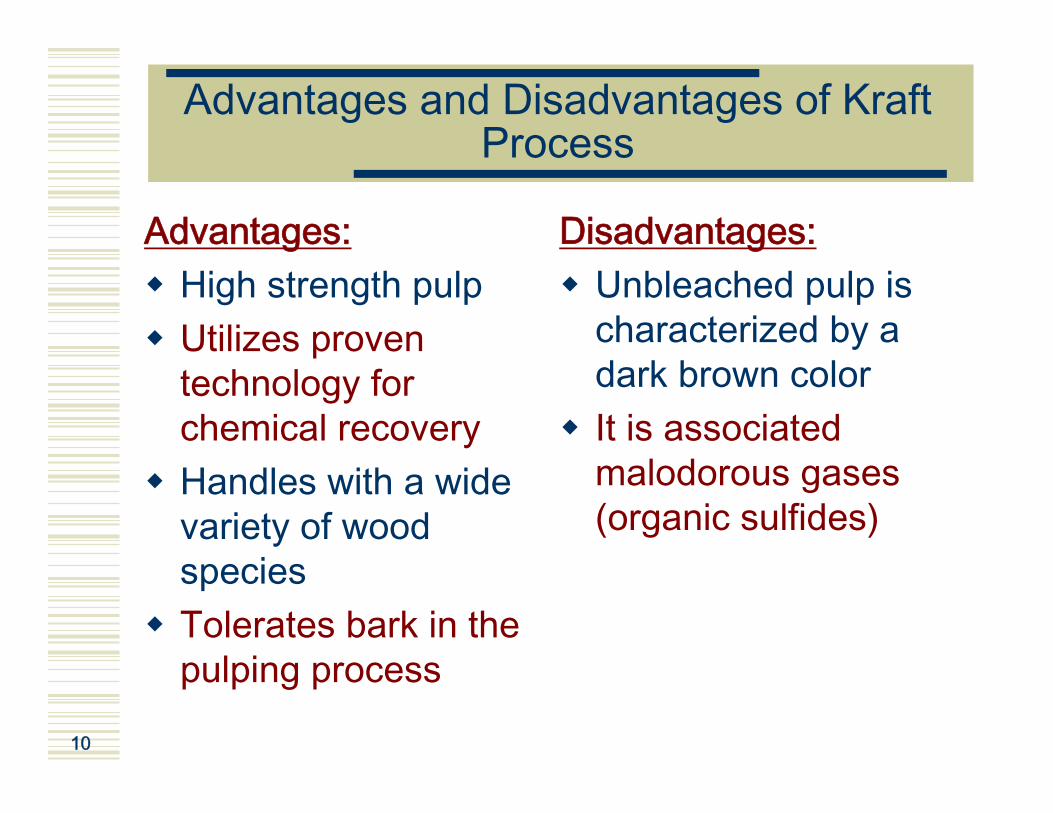
Advantages and Disadvantages of Kraft Process
Advantages:High strength pulpUtilizes proven technology for chemical recoveryHandles with a wide variety of wood speciesTolerates bark in the pulping process
Disadvantages:Unbleached pulp is characterized by a dark brown colorIt is associated malodorous gases (organic sulfides)

11
Definitions and Nomenclature (1)
White liquor:Liquor containing the active cooking chemicals (NaOH and Na2S) and used to cook chips.Black liquor:Residual liquor from cooking containing the reaction products of lignin solubilization. This liquor is concentrated and burnt into a recovery furnace and yields an inorganic smelt of Na2CO3. Green liquor:Liquor obtained by dissolving the latter smelt. The green liquor is reacted with CaO in order to convert the Na2CO3 in NaOH and regenerate the white liquor.
Cooking&
Washing
ChipsPulp
Evaporation&
BurningCausticizing
BLACK LIQUORAlkali ligninHydrolysis saltsSulphonationproducts
WHITE LIQUORNAOHNA2S
GREEN LIQUORNa2CO3Na2S
The kraft sodium cycle(Source:Smook, 1994)

12
Definitions and Nomenclature (2)
% (on a Na2O basis)Na2S / (soda sulfur coumpounds) ratio (oftensimplified as Na2S / [Na2S + Na2SO4 ] ratio)
Reduction Efficiency(Green liquor)
g/L as Na2OAlkali concentration determined by titrationResidual Alkali (Black liquor)
% (on a Na2O basis)
Same as causticity. (However, the concentration of NaOH in the green liquor should be subtracted so that the value of NaOH represents only the portion produced by the causticizing reaction.)
Causticizing Efficiency(White liquor)
% (on a Na2O basis)Na2S / AA (or TTA) ratioSulfidity% (on a Na2O basis)NaOH / [NaOH + Na2CO3] ratioCausticity
%AA / TTA ratioActivityg/L as Na2OTotal NaOH + ½ Na2SEffective Alkali (EA)g/L as Na2OTotal NaOH + Na2SActive Alkali (AA)g/L as Na2OTotal NaOH + Na2S + Na2CO3Total Titrable Alkali (TTA)
g/L as Na2OTotal of all viable sodium alkali compounds i.e. NaOH + Na2S + Na2CO3 + Na2SO4 + Na2S2O3 + Na2SO3 (does not include NaCl)
Total Alkali
UNITSDEFINITIONTERM
(Source:Smook, 1994)

13
Sodium vs. Calcium Cycle
(Adapted from European Comission IPPC, 2001)

14
Wood Fibers
Pulp fibers are manufactured by chemically dissolving those wood components (mainly lignin) that keep wood cells together to form the original wood structure by minimizing the damages to these components.
Wood
Lignin Extractive
Carbohydrates
TerpenesResin acids (softwood)Fatty acidsPhenolsUnsaponifiables
2-8%21% Hardwoods25% Softwoods
HemicelluloseCellulose45%35% Hardwoods25% Softwoods
GlucoseMannoseGalactoseXyloseArabinnose
Glucose
Chemical Components of Wood Structure of cellulose
Source: Smook, 1994

15
Overview of the Kraft Process
Digester
Chips
Blow tank
Washers
Weak black liquor storage
Evaporators
Strong black liquor storage
White liquorclarifier
Causticizers
Slaker
Green liquorstorage
Green liquorclarifier
Dissolving tankRecoveringfurnace
Lime mudwasher
Lime mudthickener
Lime kiln
Dregswasher
Weak liquorstorage
White liquorstorage
Water
Contaminatedcondensates
Pulp to bleaching
Grits Lime
WeakLiquorstorage
Lime mud
Water
DregsDregs
Smelt
Source: Smook, 1994

16
Overview of the Kraft Process
Digester
Chips
Blow tank
Washers
Weak black liquor storage
Evaporators
Strong black liquor storage
White liquorclarifier
Causticizers
Slaker
Green liquorstorage
Green liquorclarifier
Dissolving tankRecoveringfurnace
Lime mudwasher
Lime mudthickener
Lime kiln
Dregswasher
Weak liquorstorage
White liquorstorage
Water
Contaminatedcondensates
Pulp to bleaching
Grits Lime
WeakLiquorstorage
Lime mud
Water
DregsDregs
Smelt
Source: Smook, 1994
The wood is mechanically debarked and cut into chips that are screened prior the chemical treatment.Lignin and some carbohydrate material are dissolved from wood chips during cooking in aqueous solution of alkaline, neutral or acidic components at elevated temperature and pressure.Chips maintain their wood structure during chemical pulping but this latter is so weak that it will break down to individual fiber by modest mechanical action.
17
Overview of the Kraft Process
Digester
Chips
Blow tank
Weak black liquor storage
Evaporators
Strong black liquor storage
White liquorclarifier
Causticizers
Slaker
Green liquorstorage
Green liquorclarifier
Dissolving tankRecoveringfurnace
Lime mudwasher
Lime mudthickener
Lime kiln
Dregswasher
Weak liquorstorage
White liquorstorage
Water
Contaminatedcondensates
Grits Lime
WeakLiquorstorage
Lime mud
Water
DregsDregs
Smelt
Source: Smook, 1994
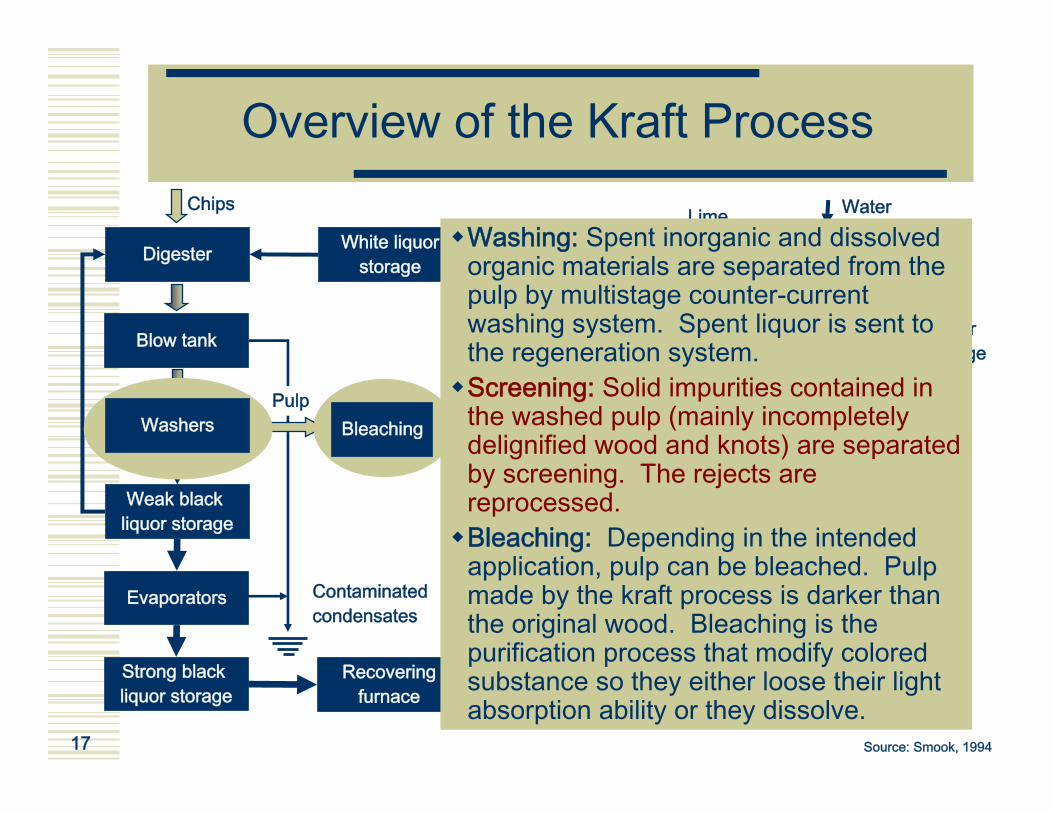
Washing: Spent inorganic and dissolved organic materials are separated from the pulp by multistage counter-current washing system. Spent liquor is sent to the regeneration system.Screening: Solid impurities contained in the washed pulp (mainly incompletely delignified wood and knots) are separated by screening. The rejects are reprocessed.Bleaching: Depending in the intended application, pulp can be bleached. Pulp made by the kraft process is darker than the original wood. Bleaching is the purification process that modify colored substance so they either loose their light absorption ability or they dissolve.
PulpWashers Bleaching

18
Overview of the Kraft Process
Digester
Chips
Blow tank
Washers
Weak black liquor storage
Evaporators
Strong black liquor storage
White liquorclarifier
Causticizers
Slaker
Green liquorstorage
Green liquorclarifier
Dissolving tankRecoveringfurnace
Lime mudwasher
Lime mudthickener
Lime kiln
Dregswasher
Weak liquorstorage
White liquorstorage
Water
Contaminatedcondensates
Grits Lime
WeakLiquorstorage
Lime mud
Water
DregsDregs
Smelt
Source: Smook, 1994
In order to be used as a fuel, kraft liquor must be evaporated in a multistage evaporation system.
PulpBleaching

19
Bleaching
Overview of the Kraft Process
Digester
Chips
Blow tank
Washers
Weak black liquor storage
Evaporators
Strong black liquor storage
White liquorclarifier
Causticizers
Slaker
Green liquorstorage
Green liquorclarifier
Dissolving tankRecoveringfurnace
Lime mudwasher
Lime mudthickener
Lime kiln
Dregswasher
Weak liquorstorage
White liquorstorage
Water
Contaminatedcondensates
Grits Lime
WeakLiquorstorage
Lime mud
Water
DregsDregs
Smelt
Source: Smook, 1994
The strong black liquor is then burned in a recovery furnace where inorganic substances are converted into regenerable substances.Sodium and sulfur salts are converted to a smelt of Na2S and Na2CO3 and brought to a dissolved tank
Pulp

20
Overview of the Kraft Process
Digester
Chips
Blow tank
Washers
Weak black liquor storage
Evaporators
Strong black liquor storage
White liquorclarifier
Causticizers
Slaker
Green liquorstorage
Green liquorclarifier
Dissolving tankRecoveringfurnace
Lime mudwasher
Lime mudthickener
Lime kiln
Dregswasher
Weak liquorstorage
White liquorstorage
Water
Contaminatedcondensates
Grits Lime
WeakLiquorstorage
Lime mud
Water
DregsDregs
Smelt
Source: Smook, 1994
The smelt is dissolved in weak wash liquor from the recausticizing plant.
PulpBleaching

21
Overview of the Kraft Process
Digester
Chips
Blow tank
Washers
Weak black liquor storage
Evaporators
Strong black liquor storage
White liquorclarifier
Causticizers
Slaker
Green liquorstorage
Green liquorclarifier
Dissolving tankRecoveringfurnace
Lime mudwasher
Lime mudthickener
Lime kiln
Dregswasher
Weak liquorstorage
White liquorstorage
Water
Contaminatedcondensates
Sour
ce: S
moo
k, 1
994
Grits Lime
WeakLiquorstorage
Lime mud
Water
DregsDregs
Smelt
Source: Smook, 1994
The green liquor is clarified.
PulpBleaching

22
Overview of the Kraft Process
Digester
Chips
Blow tank
Washers
Weak black liquor storage
Evaporators
Strong black liquor storage
White liquorclarifier
Causticizers
Slaker
Green liquorstorage
Green liquorclarifier
Dissolving tankRecoveringfurnace
Lime mudwasher
Lime mudthickener
Lime kiln
Dregswasher
Weak liquorstorage
White liquorstorage
Water
Contaminatedcondensates
Grits Lime
WeakLiquorstorage
Lime mud
Water
DregsDregs
Smelt
Source: Smook, 1994
The green liquor is causticized with reburned lime to form white liquor:CaO and water are reacted in a slaker to form CaOH, which in turn reacts with Na2CO3 in the green liquor to form NaOH and CaCO3.The CaCO3, which is insoluble, is separated by filtering and iswashed free from sodium salts.It is then calcinated in a lime kiln to CaO and reused.The regenared white liquor is reused in cooking.
PulpBleaching

23
Pollutants in the P&P Industry
What is a pollutant?A pollutant is “a substance that can alter the natural environment”(Springer and al., 2000).
US EPA classification of pollutantsOxygen-demanding substancesDisease-causing agentsSynthetic organic compoundsPlant nutrientsInorganic chemical and mineral substancesSedimentsRadioactive substancesThermal discharges

24
Environmental Impacts of the Kraft Process
Digester
Chips
Blow tank
Washers
Weak black liquor storage
Evaporators
Strong black liquor storage
White liquorclarifier
Causticizers
Slaker
Green liquorstorage
Green liquorclarifier
Dissolving tankRecoveringfurnace
Lime mudwasher
Lime mudthickener
Lime kiln
Dregswasher
Weak liquorstorage
White liquorstorage
Water
Contaminatedcondensates
Pulp Grits Lime
WeakLiquorstorage
Lime mud
Water
DregsDregs
SmeltSour
ce: S
moo
k, 1
994
Wood preparation To learn about major environmental impacts of the kraftprocess: Click on the yellow then pink boxes!
Bleaching

25
Wood Preparation
Air Pollution:Transportation of logs, production, screening, transportation and storage of chips as well as debarking activities can result in the emission of particulate matters. That are extremely difficult to measure.
Another type of fugitive emission associated with wood preparation activities is gaseous such as volatile organic compounds (VOC).
Water Pollution:Water is used for 3 purposes: log conveyance?, log washing and wet debarking.
Return to theflowsheet
For more information

26
Pulp Production
Air Pollution:The cooking process results in formation and releases of VOC’sand reduced components (TRS) that are odorous.
These compounds can exit the digester either in gaseous or liquid form. The gas are sent to condensers to remove water and other condensable compounds.
The non-condensable gas are incinerated in order to eliminate the odorous ones.
The remainder are condensed and used to pre-heat the chips.
Water Pollution:Wood chips are cooked in aqueous solution.
Return to theflowsheet
For more information

27
Pulp Washing, Screening andDeknotting
Air Pollution:The pulp washing, screening and deknotting do not result in new pollutant but volatile compounds contained in the pulp can escape during those operations.
Water Pollution:Pulp is washed to remove pulping chemicals and soluble wood components and diluted with water.
Return to theflowsheet
For more information

28
Bleaching: Oxygen Delignification (OD) – Air Pollution
In OD, steam, caustic (as oxidized white liquor), and oxygen are added to the pulp in order to reduce the lignin content before further bleaching. VOC’s are present in the incoming pulp, white liquor and washer shower water and can be released.
CO2 and CO are formed in the reactor during the delignification.

29
Bleaching – Air Pollution
Bleaching occurs in a multistep process involving the use of chemicals that will oxidize and dissolve the lignin. Following this process, the cellulose and the hemicellulose will be separated from the undesirable material. This process also involves chemical utilization.
Traditionally, chlorine was used in the first stage of bleaching but it was replaced by ClO2 because of the possible formation of unwanted chlorine compounds. Use of sodium hypochlorite in the third stage has also mostly been discontinued because of concerns related with chloroform and AOX formation.
Exhausts gases from bleaching will contain VOC’s, unreactedbleaching chemical, and inadvertently formed compounds. Most VOC’s are returned to the unbleached pulp slurry. It is also possible that ClO2 and Cl are present in small amounts in the bleach plant gases.
CO is mostly formed in the first stage of bleaching.

30
Bleaching – Water Pollution
Different chemicals are used in a multi-stage process to bleach the pulp. Aqueous washing is performed between stages to remove bleaching chemicals and any dissolved wood components extracted during bleaching.
Water is also used to prepare bleaching chemical solutions and in air emission control scrubbers.
Because waste water from bleaching usually has a high content in content in chlorine, it is incompatible with chemical recovery process and it is sent directly to the wastewater treatment.
Return to theflowsheet
For more information

31
Chemical Recovery:Evaporation
Air Pollution:
Following the cooking, the spent cooking liquor referred to as weak black liquor. This liquor is composed of around 85% water and 15% solids that are a complex mixture of sulfur and sodium containing organic and inorganic compounds.
During the evaporation of water, gaseous volatile compounds can be formed. Also, because of the presence of sodium sulfide in Kraft cooking liquor, TRS compounds can be released during the evaporation. To avoid bad odors, these gas are sent to combustion in order to oxidize the TRS.
Water Pollution:
Water from weak black liquor is evaporated and the condensates from the evaporators comprise the excess water from liquor concentration. These condensates can be reused in other processes but excess condensates are discharged to the wastewater treatment.
The condensates can contain high level of TRS, methanol and acetone.
Return to theflowsheet
For more information

32
Chemical Recovery:Recovery Furnace – Air Pollution
When the liquor has a minimum of 60% solids, it is sent in the recovery furnace where the organic compounds are burnt and the inorganic compounds transformed in a molten smelt.
The recovery furnace is the recovery furnace is the predominant source of TRS emissions.
Particulates such as sodium sulfate and sodium carbonate are also emitted by the recovery furnace. Potassium compounds and other metals can be present in smaller quantities.
Recovery furnaces also emit SO2, NOx, CO, volatile organic compounds and other products from incomplete combustion. There is also a potential for SO3, H2SO4, HCL and NH3 emissions.
There are possibilities for other chlorinated compounds emissions but in very small quantities.
Return to theflowsheet

33
Chemical Recovery:Dissolving and Clarification – Air Pollution
Molten smelt drains from the furnace to a tank and the smelt is broken up with steam. The smelt particles fall into an agitated solution of weak wash. The mixture is called green liquor that is pumped to the clarifier where suspended solids are removed.
Most of the emissions from the dissolving tank are TRS and particulate matter that are similar to the ones from the recovery furnace.
VOC and NH3 can also be released.
Return to theflowsheet

34
Chemical Recovery:Lime Kiln
Return to theflowsheet
Air Pollution:
Lime mud is calcinated to form CaO and CO2 in the lime kiln.
Most of the emissions from the lime kiln are TRS and particulate matter.
SO2 emissions are low because of the alkaline atmosphere in the lime kiln.
Lime kiln can also emit NOx, CO and VOC from incomplete combustion.
Water PollutionWater is used to wash the solid precipitates formed in the recovery cycle. Washing recovers sodium and sulfur containing from green liquor dregs and lime mud. This weak wash is reused to dissolve recovery furnace and the excess is sent to the wastewater treatment.
For more information

35
Chemical Recovery:Slaker – Air Pollution
CaO from the kiln and green liquor from the dissolving tank are mixed together to give NaOH, CaCO3. A large amount of steam that must be ventiled is formed.
The steam contains a lot a particulate matter that are mostly calcium and sodium carbonates and sulfates.
NH3 can also be formed.
Return to theflowsheet

36
Chemical RecoveryOther Causticizing Area Equipment
Air Pollution:
Other equipment associated with the processing of green liquor (clarifiers, storage, surge tanks and dregs washers), white liquor (causticizers tanks, clarifiers, pressure filters and storage tanks), and lime mud (mix tanks, dilution tanks, storage tanks, pressure filters and pumps) can vent to the atmosphere.
However, gas flow rates such as VOC and NH3 from this equipment are usually very small and concentrations low.
Return to theflowsheet

37
Representative Bleached Kraft Mill Water Loads
The highest volume of discharges comesfrom the paper mill.The largest BOD loads occur at thebleach plant.The paper millprocess the highestamount of TSS.
(Source: Springer and al., 1997)
Return to Lime Killn Return to Evaporation Return to Bleaching Return to Pulp Washing
Return to Pulp Production Return to Wood Preparation

38
Most Impacting Environmental Regulations
Legislation is one of the drivers for implementing environmental changes and it is also recognized as a important factor to conserve an advantage over competitors.Also, there is a consensus that legislations will be more and more stringent over the next 25 years.For this reason, the regulations that have the most significant impact on the pulp and paper industry will be described in the following slides.The importance of legislation as well as of other drivers for environmental change will be described in tier II.

39
US EPA Clean Water Act
The Clean Water Act launched in 1977 established the basic structure for regulating discharges of pollutants into the waters of the United States. By this, the USEPA has the authority to implement pollution control programs (e.g. setting wastewater standards for industry).It aims at reducing direct pollutant discharges into waterways, finance municipal wastewater treatment facilities, and manage polluted runoff using regulatory and non-regulatory tools.

40
US EPA Cluster Rule
The US EPA Cluster Rule integrates air and water regulations.It was first published in 1998 and was applying to bleachedpaper grade kraft, soda and paper grade sulfite mills.Key features of the Cluster Rule are:
Implementation within 3 years;Bleach plant eflluent limitations for dioxin, chlorinated phenolics, and chloroform;AOX limitations;Establishment of best management practices (BMP) for control of spills of spent pulping liquor, turpentine and soap;Encouragement of project XL;No Change on BOD and TSS limits;No limits on color, methylene chloride, or methy ethyl ketone;No current COD limitations, but it changes in the future.

41
US EPA Project XL
Project XL stands for "eXcellence and Leadership” and is a US pilot program that allows state and local governments, businesses and federal facilities to develop with EPA innovative strategies to test better or more cost-effective ways of achieving environmental and public health protection. Project XL has 8 selection criteria:
1. Produce superior environmental results beyond those that would have been achieved under current and reasonably anticipated future regulations or policies;
2. Produce benefits such as cost savings, paperwork reduction, regulatory flexibility or other types of flexibility that serve as an incentive to both project sponsors and regulators;
3. Supported by stakeholders; 4. Achieve innovation/pollution prevention; 5. Produce lessons or data that are transferable to other facilities; 6. Demonstrate feasibility; 7. Establish accountability through agreed upon methods of monitoring, reporting,
and evaluations; and 8. Avoid shifting the risk burden, i.e., do not create worker safety or environmental
justice problems as a result of the experiment.
In addition, projects must present economic opportunities and incorporate community planning.

42
Industrial Depollution Attestations (Quebec)
Program for Industrial Waste Reduction:The Program for waste reduction was launched in 1988. Quebec Ministry of Environment has developed an intervention strategy integrating all receiving medias. The target industrials sectors were those whom contaminant rejects, more specifically releases of toxic substances had the largest impacts on local environments.Industrial Depollution Attestations:The Industrial Depollution Attestation is the legal tool that allows the ministry to operationalyze the Program for Waste Reduction.

43
Industrial Depollution Attestations (Quebec)
The Industrial Depollution Attestation is a permit, renewable every 5 years, that establishes the environmental conditions under which the industry must operate.The Industrial Depollution Attestation main components are:
Reject standards to respect;Requirements related to rejects follow-up;Other operation conditions as determined by the ministry;Studies to perform;Due dates and additional requirements.
Targeted Sectors:Pulp and Paper (is the only one to have completely implemented the program to date);Mines and Metallurgy;Organic and Inorganic Chemistry;Agri-food industry, wood transformation and textiles.
44
Integrated Pollution Prevention and Control (IPPC) - Europe
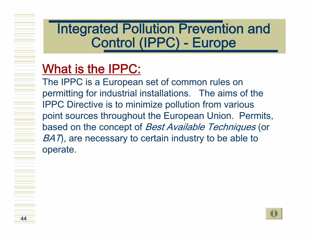
What is the IPPC:The IPPC is a European set of common rules on permitting for industrial installations. The aims of the IPPC Directive is to minimize pollution from various point sources throughout the European Union. Permits, based on the concept of Best Available Techniques (orBAT), are necessary to certain industry to be able to operate.

45
Kyoto Protocol and GHG Mitigations
Climate change is a problem which affects all countries. Many human activities emit greenhouse gases (GHGs) to the atmosphere ( heating and cooling buildings, using energy,transportation, industrial processes, etc.). When in contact with the sun radiations, the GHGs act like a greenhouse's glass to block this heat from escaping back to space increasing the earth temperature.
In1997, more than 160 countries met in Kyoto (Japan), and agreedto targets to reduce GHG emissions. This agreement is called theKyoto Protocol. Canada's target is to reduce its GHG emissions to 6 percent below 1990 levels by the period between 2008 and 2012.
The Protocol will only become legally binding when it is ratified by at least 55 countries, covering at least 55 per cent of the emissions addressed by the Protocol. Neither USA or Mexico have ratified the protocol. At this time (May 2004) the implementation is pending ratification by either USA or Russia.

46
GHG Mitigations & Pulp and Paper
In 2003, the Forest Products Association of Canada has sign an agreement with the Canadian government concerning the GHG emissions which includes a commitment by the industry to reduce its greenhouse gas (GHG) emissions intensity by an average of 15 percent by 2008 to 2012, the first Kyoto commitment period.

47
References
ENVIRONNEMENT QUÉBEC. 2003. Le Programme de réduction des rejets industriels et l’attestation d’assainissement.http://www.menv.gouv.qc.ca/programmes/prri/index.htm (page consulted in 2004)EUROPEAN COMISSION. Integrated Pollution Prevention and Control (IPPC) –Reference Document on Best Available Techniques in the Pulp and Paper Industry. 2001, 475 p.Gullichsen, J. Fogelholm, C-J. (eds). Papermaking Science and Technology, Chemical Pulping, Book 6A. Tappi Press, Helsinki, Finland, 2000, 693 p. SMOOK, G.A. Handbook for pulp & paper technologists. 2nd ed. Angus Wilde Publications, Vancouver, Canada, 1992, 419 p.SPRINGER, Allan M. (ed.) Industrial Environmental Control – Pulp and Paper Industry. 3rd ed. Tappi Press, Atlanta, USA, 2000, 711 p.USEPA. 2003. Project XL. http://www.epa.gov/ProjectXL/ (page consulted in 2004)USEPA. 2003. Industrial Water Pollution Controls.http://www.epa.gov/OST/pulppaper/cluster.html (page consulted in 2004).

1.2 Introduction to minimum impact manufacturing (MIM)

49
Content
A. MIM conceptsB. Progressive water system closure and
build-up of NPE’sC. Zero discharge conceptsD. Tracking models for water, NPE’s, and
targeted speciesE. Kraft mill energy efficiencyF. Relation between minimum energy and
minimum effluentG. BAT conceptsH. Example of application of MIM concept

50
Content
A. MIM conceptsB. Zero discharge conceptsC. Progressive water system closure and
build-up of NPE’sD. Tracking models for water, NPE’s, and
targeted speciesE. Kraft mill energy efficiencyF. Relation between minimum energy and
minimum effluentG. BAT conceptsH. Example of application of MIM concept

51
Weyerhaeuser’s Vision of MIM
Minimum impact manufacturing (MIM) concept has first been introduced by Weyerhaeuser:
“Using a Minimum Impact Manufacturing strategy, Weyerhaeuser directs its efforts to manufacturing
quality products with minimal environmental impact and maximum return to shareholders. The strategy works to
prevent pollution by continuously reducing process byproducts and finding ways to capture, reuse or
recycle them.”(Weyerhaeuser website, 2004)

52
Weyerhaeuser’s Vision of MIM
For a production facility MIM includes Weyerhaeuser's commitment to strive to close the loop by further:
Optimizing raw materials used at the mill level Reducing water usage Minimizing fossil fuel for energy in manufacturing Reducing/eliminating hazardous waste Generating less solid waste Reducing emissions to all media Eliminating spills Reusing and recycling from our mills the materials and residualsthat previously went to landfills Collecting and recycling used waste paper for use as a rawmaterial
(Weyerhaeuser website, 2004)

53
Goals of MIM
Minimum Impact Manufacturing aims to:Eliminate process issues before they become environmental problems.Address multiple environmental areas, including air and water quality, solid and hazardous waste minimization and more.Use science and economics to focus on pollution prevention at the source rather than end-of-pipe remedies.
(Weyerhaeuser website, 2004)

54
Environmental Hiearchy of Needs
Acute Impacts on the environment
Chronic and/or Long-Term Effects
Subtle, Complex, Aesthetic
MinimumImpact
Resource depletionacute toxicity,raw effluent,etc.
Energy, odor, color,biodiversity, etc.
Completion of theForest products cycle
Chronic toxicity,bioaccumulation,etc.
Source: Erickson, Zacher and Decrease, 1996

55
Key Environmental ParameterRelated to MIM
Accidental ReleasesNon-Compliant Events SARA 313 ReleasesEnergy Use/Energy ExportsAesthetics: - Site Appearance - Odor - Noise Improvement Projects Chemical Management Key Environmental Accomplishments
Solid Waste GeneratedSolid Waste Disposition:- Landfill - Recycled - Energy Reduction Plans/AchievementsHazardous Waste Elimination
Particulate TRS Methanol Chloroform Chlorine Chlorine
Dioxide CO/CO2 NOxSO2 VOCsOpacity HAPS
Water UsageBleach Plant Effluent Volume Final Effluent Volume BOD COD TSS Effluent AOX Dioxin Color Chronic Toxicity Nutrients
OtherSolid WasteAirWater

56
Content
A. MIM conceptsB. Zero discharge conceptsC. Progressive water system closure and
build-up of NPE’sD. Tracking models for water, NPE’s, and
targeted speciesE. Kraft mill energy efficiencyF. Relation between minimum energy and
minimum effluentG. BAT conceptsH. Example of application of MIM concept

57
Goal of Process Closure
The goal of process closure with respect to effluent discharges is to minimize theamount of waste generated. This can beaccomplished by:
Using more efficient processes;Using processes that do not require water;Recovering the waste materials.
(Source, NCASI, 2003)

58
Rapson-Reeve Process
In 1967 Rapson proposed a bleached kraft pulpmanufacturing process that had the potential to greatly reduce, if not eliminate, effluent discharges.The idea was based on a collection of technologies, including incresed use of chlorine dioxide for bleaching and a process for generating this chemicalthat could be fully integrated with the chemicalrequirements of the kraft pulping and bleachingprocesses.The driver for this process was a cost effective alternative to the biological effluent treatment.The process was implemented by the Great Lakes Paper mill in Thunder Bay, but abandoned.

59
Rapson-Reeve Process
The original effluent-free mill concept was based on thefollowing ideas:
Replace 70-80% of the chlorine in the chlorination stage withan equivalent amount of chlorine dioxide.Use a new chlorine dioxide generating process.Use countercurrent washing in bleach plant, usingwastewater from the wet end of the pulp dryer or papermachine to minimize de volume of filtrate to be recovered.Use a portion of the bleaching filtrate to wash theunbleached filtrate, allowing the dissolved from bleaching to be recovered via evaporation and burning.Use the remainder of the bleaching filtrate to wash the lime mud and green liquor dregs and to dissolve the smelt fromthe recovery furnace.

60
Rapson Reeve Process
Effluent-free concept (Cont’d):Treat the evaporator condensates with a small amount of chlorine dioxide to oxidize the foul-smelling compounds and use the oxidized condensates in place of fresh water on the wet end of the pulp dryer or paper machine.Remove the sodium chloride from the liquor cycle by extracting it from the recovery furnace flue gas in the electrostatic precipitator. A portion of the extract would be used to generate chlorine dioxide for the bleach plant and the remainder would be discarded.Establish closed water systems for wood debarking, pulp screening, and cleaning.

61
Main Problems in Making a Mill Effluent-Free
Non-process elements can accumulate.Pulp quality can be affected.About one quarter of the water pollution in bleached pulp millscomes from spills and wash-up and are not well controlled.Calcium trap: when there is any acid stage in the bleachingsequence (ozone), calcium carbonate will travel with the pulp in neutral or alkaline stages, but dissolve in acid stages. If countercurrent washing is used, the calcium will be precipitated intothe pulp in any previous alkaline stage and carried forward to be re-dissolved in acid stage.In order to obtain the appropriated displacement ratio and purge for each stage, the flow of filtrate in and out must be preciselybalanced.In order to minimize the consumption of oxidizing agent in subsequent stages throught incomplete washing, the concentration of organic matter in each filtrate must be carefully controlled.

62
Process Closure Technologies
Definition:Process closure technologies can be defined as those which effect or enable the reduction of waterborne wastes from pulp manufacturing facilities. They serve to divert wood components and other raw materials from liquid waste streams by prevention, reuse, or recovery.These technologies were largely driven by the desire to limit the discharge of chlorinated organic compounds.

63
Zero Discharge Concept
For a majority of pulp mills zero-effluent discharge is impracticable.Currently, zero effluent operation appears to be restricted to plants producing bleached chemical thermal mechanical pulp and non-chlorine bleaching agents. Since the bleach plant is the major source of contaminated effluent in a kraft pulp mill, the closure of these circuits is an essential prerequisite for producing a zero-effluent kraft mill.This requires the simultaneous resolution of a number of problems:
water balance, chemicals balance, corrosion, precipitation of salts and removal of non-product substances.

64
Low Effluent Kraft Mill ExamplesNewest Mills of America
The 3 newest mills of America were designed to be highly economical and environmentally performing using high capacity, single line facilities, and employing modern technology for pulp production and effluent treatment. None of these mills practices recovery of bleaching wastewaters but their effluent quality is among the best in the world. These mills are:
Bahia Sul, Brazil;Alabama Pine Pulp, USA;Alberta-Pacific, Canada.

65
Low Effluent Kraft Mill ExamplesMill Practicing Recovery of Bleaching Filtrates
Linerboard mills:AssiDomän Frövi, Swenden;Kappa Kraftliner (formerly AssiDomän) Piteå, Sweden;SCA Munksund, Sweden.

66
Low Effluent Kraft Mill ExamplesMill Practicing Recovery of Bleaching Filtrates
Bleached papergrade kraft mills:Blue Ridge Paper Products – Canton, North Carolina, U.S.A.International Paper Company – Franklin, Virginia, U.S.A.Aspa Bruk – Smurfit Munksjö, SwedenM-Real Sverige AB – Husum, SwedenSCA Pulp AB – Östrand, SwedenSödra Cell – Mörrum, SwedenSödra Cell – Värö Bruk, SwedenStora Enso – Skoghall, SwedenMetsä-Botnia – Rauma, FinlandUPM-Kymmene Wisaforest – Pietarsaari, Finland

67
Content
A. MIM conceptsB. Zero discharge conceptsC. Progressive water system closure and
build-up of NPE’sD. Tracking models for water, NPE’s, and
targeted speciesE. Kraft mill energy efficiencyF. Relation between minimum energy and
minimum effluentG. BAT conceptsH. Example of application of MIM concept

68
Progressive Water System Closure
Conventional methods to achieve water closure are simple andinclude:
Using counter-current washing in pulping and bleaching operations;Closing brownstock screen room;Using dry debarking;Using evaporator condensate for brownstock washing;Recycling excess whitewater from paper machine to bleach plant;Reusing stripped condensates from steam stripping of foul condensates;Using equipment and process that require less water;Using cooling towers for vacuum pump seal water an non-contact cooling water;Using first bleach stage washer/filtrate to dilute brown high-density stock;Recycle/reuse secondary and/or tertiary treated effluent;
Applicating changes to pulping and bleaching practices will furtherstrive to the closure.

69
Non Process Elements (NPEs)
NPEs are materials such as potassium (K), phosphorus (P), manganese (Mn), magnesium (Mg), iron (Fe), aluminium (Al), silicon (Si), calcium (Ca), barium (Ba), andchlorine (Cl) that enter the chemical pulpingprocess with the wood, water and chemicals.When we decrease fresh water consumption, there is a potential for increasing theconcentration of some troublesomesubstances and more specifically NPEs.

70
NPEs Consequences
NPEs accumulate in the sodium and calcium cycle in kraft process potentially causing the followingconsequences:
Corrosion of the recovery boiler and other equipment;Deposits on the boiler tubes that reduce heat transfer;Scale in the digester, evaporators, and heat exchangers;Blinding of white liquor and lime mud filters;Reduced reburned lime reactivity;Ring formation in the lime kiln;Increased dust formation in the lime kiln;Increased chemical consumption in bleaching;Reduced effectiveness of ozone and peroxide bleaching.

71
NPEs Classification
There are to catogories of NPEs:1. NPEs that form insoluble metal hydroxides
or carbonates and are removed from the sodium cycle with the dregs and grits: mostly Ca, Mg, Mn and Si.
2. NPEs that form soluble compounds in alkaline solution: mostly Al, Cl, and K.

72
Build-up of NPEs
In an « open » mill the presence of NPEs is not importance since they are purged outside the system.When progressively closing mill, many outlets are not available anymore. The consequence of this is thebuild-up of NPEs.NPEs have a tendency to accumulate in eighter thesodium or calcium cycle in the following way:Sodium Cycle: K > Cl > Al > Fe > Si > Mn > Mg > CaCalcium Cycle: Mg > Al > Fe > Mn > Si > Na > K > S > Cl
The most troublesome NPEs are K, Cl and Na. Na is the most tricky because it is a process and non-process element at the same time.

73
Content
A. MIM conceptsB. Progressive water system closure and
build-up of NPE’sC. Zero discharge conceptsD. Tracking models for water, NPE’s, and
targeted speciesE. Kraft mill energy efficiencyF. Relation between minimum energy and
minimum effluentG. BAT conceptsH. Example of application of MIM concept

74
Tracking Models for Water, NPE’s, and Targeted Species
Path diagram equation:It is a mass integration tool whose objective is to track targeted species (e.g., NPEs and water) as they propagate throughout the process and provides the right level of details to be incorporated into a mass integration analysis.A typical form of the path equations is to describe outlet flows and compositions from each critical unit as a function of inlet flow, inlet compositions, and appropriate design and operating parameters.Steps for analysis will be described in the following slides.

75
Main Characteristic of the Path DiagramEquation
In order to optimize water allocation in a pulping process, two important activities can be used together: mass integration and process simulation. Mass integration techniques handle process objectives, data, requirements and constraints. It will allow to fix performance targets, solution strategies, and proposed changes to the process.
Learn more aboutsimulation
Learn more aboutMass integration
ProcessIntegration
ProcessSimulation
Process modifications,structural changes,
Input-outputrelations,newprocess
f
ProcessObjectives, Data,and Constraints
Performance targets,Solutions, Strategies,and Insights,
Because of these changes, the performance must be reassessed using process analysis or simulation. The use of process simulation enables the update of flowrates and compositions throughout the process
(Source: Lovelady, 2001)

76
1. Degrees of Freedom
NV = NS x NC
F= NV - NE = NC (NS - 1)F: degrees of freedomNV: number of variablesNE: number of equationsNC: number of targeted speciesNS: number of outlet streams
Assumptions:All inlets to a unit are known and it is desired to determine the outputs of the unit.
F must provided as additional modeling equations, assumptions, measurements, or data in order to have an appropriately specified (determined) set of equations that is solvable.
Unit U
Inlet stream(Fresh inputs or outlets from other units)
Outlet streamsNstreams out

77
2. Mixer-Splitter Model
The mixer-splitter model is a modeling technique which relies on nominal data .The nominal data are those for the plant prior to any changes and can be obtained via simulation, fundamental modeling, direct measurements, or literature data.There are various of the mixer splitter model:
Fixed split model;Flow ratio model ;Species ratio model.
Based on the knowledge of the process, choices can be made for the selected model and streams/species.Path equations can be developed for water and targeted NPEs throughout the process.

78
Fixed Split Models
The fixed split model adopts a certain split for the flows of the various streams leaving the unit.This model is useful in predicting flows out of many units, particularly separators.
Fixed SplitModel
FαF
(1-α)F

79
Flow Ratio Model
The ratio model, relates certain streams or components via fixed ratios.The flow ratio model assumes that inlet and outlet flows of certain streams maintain a certain ratio.
Flow RatioModel
F G
G2 = G1 x F2
F1

80
Species Ratio Model
The species ratio model is another form of the ratio model. It assumes relationship between certain species within the same stream via fixed ratios. This is particularly useful when one component can be accurately tracked while another one cannot.
Flow RatioModel
FSpecy A = αSpecy B = β
B2 = A2 x (β/α )

81
Content
A. MIM conceptsB. Progressive water system closure and
build-up of NPE’sC. Zero discharge conceptsD. Tracking models for water, NPE’s, and
targeted speciesE. Kraft mill energy efficiencyF. Relation between minimum energy and
minimum effluentG. BAT conceptsH. Example of application of MIM concept

82
Energy in Kraft Mill
Kraft mills are usually partly energysufficient:
They generate power using sources such as wood wastes and spent pulping liquor.This is very important since CO2 emissions from renewable sources are not included in the greenhouse gases inventory considered under the Kyoto protocol.The emergence of new technologies will allow the kraft mill to be essentially energy-sufficient in the future.

83
Kraft Mill Energy Efficiency
To maximize operating profit a mill requires thefollowing technologies:
Since black liquor is the largest source of energy in a kraftmill, it is important to use it in an efficient way. A higher solids content will result in more steam produced and less heat going to recovery stack as water vapor.Pulping yield must be increased using new cooking technologies with reduced energy consumption.Washing and screening must be runned at higher consistencies and their performance must be increased in order to reduce the water necessary to wash the pulp.For improved steam economies and evaporation to high solids levels with scaling, modern evaporators with heat treatment can be used.

84
Kraft Mill Energy Efficiency
To maximize operating profit a mill requires thefollowing technologies:
New kiln technology with large precoat filters, flash dryers, product coolers and better insulating brick will reduce lost of heat.Screening and conditioning of chips will reduce fines generation and improve digester yield.Others:
Economies of scale are important in terms of energy consumption;Using less water will generally reduce heating requirements;Efficient mill layout will reduce friction loss associated with long piping;Etc.

85
Content
A. MIM conceptsB. Progressive water system closure and
build-up of NPE’sC. Zero discharge conceptsD. Tracking models for water, NPE’s, and
targeted speciesE. Kraft mill energy efficiencyF. Relation between minimum energy and
minimum effluentG. BAT conceptsH. Example of application of MIM concept

86
Effect of Water Closure on Energy
Effect of reducing water usage on energy flows are strong and complex.This leads to complex process designs and an increasing need for systematic and system-oriented analysis of energy and water use in the mills.On of the challenge is to deal with excess heat that increases the temperature of process streams and effluent.Process integration can be an useful tool to understand this can of problems.

87
Content
A. MIM conceptsB. Progressive water system closure and
build-up of NPE’sC. Zero discharge conceptsD. Tracking models for water, NPE’s, and
targeted speciesE. Kraft mill energy efficiencyF. Relation between minimum energy and
minimum effluentG. BAT conceptsH. Example of application of MIM concept

88
BAT Concept(Source: European IPPC)
BAT: Best Available Technology economically achievableKey characteristics of BATs:
There is no single reference of best available techniques in pulp and paper industry. In contrast, the list of techniques to consider in the determination of BAT provides a lot of different options of an overall BAT for given mills, which may be combined in different ways.The BAT-concept is process-related because the environmental impact is caused on this level i.e. by different manufacturing processes as for instance cooking, bleaching, de-inking, coating etc. The single processes, the raw materials used and the product properties to be achieved determine the emission of a mill. Thatmeans when approaching the pulp and paper industry different types of raw materials used and processes involved have to be distinguished.

89
BAT Concept(Source: European IPPC)
Key characteristics of BATs (Cont’d):As pulp and paper products are highly diverse and utilized processes even for one and the same product may vary greatly, many factors of production technology must be taken into accountto guarantee a high level of environmental protection. For the pulp and paper industry the best available techniques cannot be defined solely by describing unit processes. Instead, the whole installations must be examined and dealt with as entities. BAT in pulp and paper industry is linked to the environmental performance of mills.There are different options for suitable combinations of processes depending - besides other things - on the product properties to be achieved. As a consequence, the process-oriented approach has to be extended by a product-oriented concept i.e. the BAT approach must be linked to the environmental performance of specific types of mills where specific products are manufactured. Thus, in this document best available techniques are presented for major mill classes separately.

90
BAT - Remark
The following programs are based on BAT:
USEPA Cluster Rules;European IPPC.

91
Content
A. MIM conceptsB. Progressive water system closure and
build-up of NPE’sC. Zero discharge conceptsD. Tracking models for water, NPE’s, and
targeted speciesE. Kraft mill energy efficiencyF. Relation between minimum energy and
minimum effluentG. BAT conceptsH. Example of application of MIM concept

92
Application of MIM Concepts:The Flint River Case Study
Description of the millFlint River is a Kraft pulp mill located in Georgia, USA.It is producing 320 000 tons per year of fluff pulp.Flint River Operations' environmental performance has been recognized as superior within the bleached Kraft pulping industry.Flint River was the first bleached Kraft pulp mill to employ commercially viable advanced technologies that minimize adverse impacts to the environment such as oxygen delignification, 100% chlorine dioxide substitution and bleaching and extensive water conservation practices.

93
Application of MIM Concepts:The Flint River Case Study
Weyerhaeuser Project XL:Weyerhaeuser Company's pulp manufacturing facility in Oglethorpe, Georgia, is striving to minimize the environmental impact of its manufacturing processes on the Flint River and surrounding environment by pursuing a long-term vision of a Minimum (environmental) Impact Mill. Weyerhaeuser Company is taking immediate steps by decreasing water use and meeting or exceeding all regulatory targets. EPA and the State of Georgia have agreed to propose changes in the rules to support minimum impact manufacturing. The Final Project Agreement was signed on January 17, 1997.

94
Application of MIM Concepts:The Flint River Case Study
MIM phases at Flint RiverMIM Phase I (1979-1980)
Original Facility DesignOxygen DelignificationExtensive Water Recycle / ReuseChlorine/Chlorine Dioxide Bleaching Air Emissions / Low Odor / BACT/ NSPS Extensive Wastewater Treatment
MIM Phase II (1981-1985)River & Lake Environmental StudiesHolding Pond Addition / Delta Color ManagementProcess Reliability I (Rate/Surge)Spill Containment & Liquor Best Management Practices

95
Application of MIM Concepts:The Flint River Case Study
MIM phases at Flint RiverMIM Phase III (1986-1995)
Process Reliability II (Statistical Process Control)Elimination Of Molecular ChlorineBleach Plant & Chemical Generator CollectionEmergency Response Team (Fire/Hazmat/EMT/Confined Space)ISO 9000 Certification
MIM Phase IV (1996-1997)Isothermal CookingOdor Control System UpgradeEnergy Steam ReductionsISO 14001 Environmental Management System (EMS)

96
Application of MIM Concepts:The Flint River Case Study
MIM phases at Flint RiverMIM Phase V
Bleach Plant Effluent ReductionsSolid Waste ReductionsTimberland Resource StrategiesWater Use ReductionEnergy ConservationHazardous Air Pollutant (HAP) Emission Reductions
MIM Phase VI:Life Cycle Inventory

97
References
EUROPEAN COMISSION. Integrated Pollution Prevention and Control (IPPC) – Reference Document on Best Available Techniques in the Pulp andPaper Industry. 2001, 475 p.LOVELADY, EVA M. An Integrated Approach to the Optimization of Water Usage and Discharge in Pulp and Paper Plants. Auburn University, USA, 2002, 185 p.Minimum Impact Manufacturing. 1996 International Environmental Conference & Exhibits. 1996, p.623-628.NCASI. Pulp Mill Process Closure: A Review of Global Technology Developments and Mill Experiences in the 1990s. Technical Bulletin No. 860, May 2003, 108 p.PAPRICAN. Energy cost reduction in the pulp and paper industry. Pointe Claire, QC, Canada : Pulp and Paper Research Institute of Canada, 1999. USEPA. Project XL – Weyerhaeuser Company. http://www.epa.gov/projectxl/weyer/index.htm (page consulted in 2004).WEYERHAEUSER. 2001. Minimum Impact Manufacturing. http://www.weyerhaeuser.com/environment/reducingpollution/minimumimpactmfg.asp (page consulted in 2004)

1.3 Related PI Tools

99
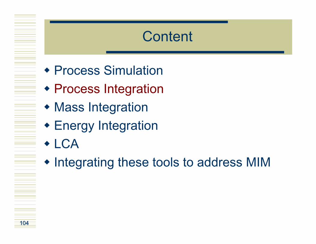
Content
Process SimulationProcess IntegrationMass Integration Energy Integration LCAIntegrating these tools to address MIM

100
Content
Process SimulationMass Integration Energy Integration LCAIntegrating these tools to address MIM

101
What is a Model? A Simulation?
A model is an abstraction of a process operation used to build, change, improve or control that process.Models are useful for:
Equipment design, sizing, selectionComparison of possible configurationsEvaluation of process performance against limits (e.g. concentrations, effluent discharge rates, …)Debottlenecking and optimizationControl strategy development and evaluation
Simulation involves performing a series of experiments with a process model.
Return to PathDiagram Equation

102
Benefits of Simulation
Better understanding of the processConsistent set of typical mill dataObjective comparative evaluation of options for ROI etc.Identification of bottlenecks, instabilities etc.Perform many experiments cheaply once model builtAvoid implementing ineffective solutions
Return to PathDiagram Equation
103
Models Are Only an Approximation of theReality
There is many type of models:
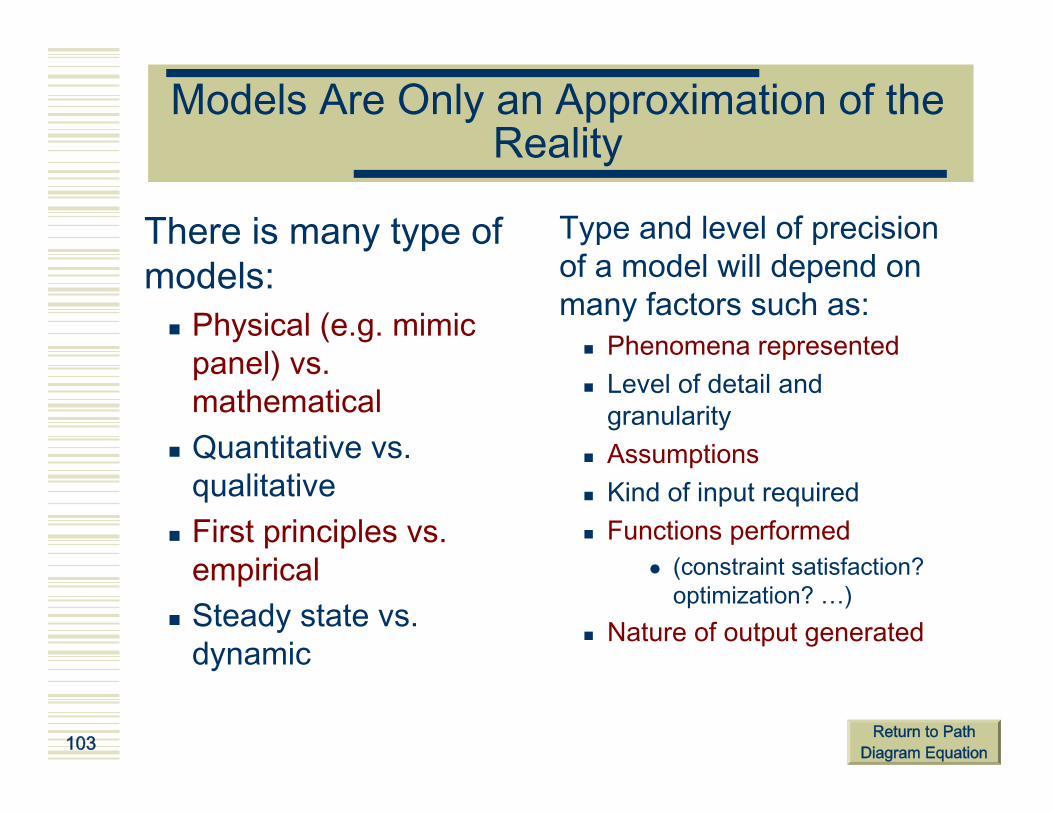
Physical (e.g. mimic panel) vs. mathematicalQuantitative vs. qualitativeFirst principles vs. empiricalSteady state vs. dynamic
Type and level of precision of a model will depend on many factors such as:
Phenomena represented Level of detail and granularityAssumptions Kind of input requiredFunctions performed
(constraint satisfaction? optimization? …)
Nature of output generated
Return to PathDiagram Equation
104
Content
Process SimulationProcess IntegrationMass Integration Energy Integration LCAIntegrating these tools to address MIM

105
Process Integration
Definitions:“Process integration is a holistic approach to process design, retrofitting, and operation which emphasizes the unity of the process.”(El-Halwagi, 1997)“The holistic analysis of processes involving the following elements:
Process data;Systems and tools;Process engineering principles and in dept process sector knowledge.”(Stuart, 2002)

106
Content
Process SimulationProcess IntegrationMass IntegrationEnergy Integration LCAIntegrating these tools to address MIM

107
Mass Integration
Definition:“Systematic methodology that provides a fundamental understanding of global flows of mass within the process and employs this holistic understanding in identifying performance targets and optimizing the generation and routing of species throughout the process” (El-Halwagi, 1997)
Pollution prevention is one of the most importantobjectives of mass integration!
Return to PathDiagram Equation

108
Principles of Mass Integration
Mass integration is based on chemical engineering principlescombined with system analysis.Mass flow must be represented from a species viewpoint:
For each targeted species, there are sources (streams that carrythe substances) and sinks (reactors, heaters/coolers, etc.).Streams living the sinks become sources.The sinks can be generator of targeted species.Each sink/generator can be manipulated through design or their operations can be changed in order to affect the flow rate and composition of what each sink/generator accepts as discharges.
Sources are generally prepared for sinks through segregation and separation via waste interception network.Effective pollution prevention can be reached by combination of stream segragation, mixing, interception, recycle from sources to sinks and sink/generator manipulations.
Return to PathDiagram Equation

109
Sources(back toprocess)
Sinks/Generators
SegregatedSources
Sources
Segregation, Recycle, Interception and Sink/Generator Manipulation
Segregation: Avoiding the mixing of the streams.Recycle: Utilization of pollutant-laden stream (a source) in a process unit (a sink).Interception: Utilization of separation unit operation to adjust the composition of the pollution-laden streams to make them acceptable for sinks.Sink/Generator manipulation: Design or operation of changes that alter the flowrate or composition of pollutant-laden streams entering or leaving the process units.
WasteInterception
Network
2
1
Nsink
Mass and Energy-SeparatingAgents In
Mass and Energy-SeparatingAgents Out
(To Regeneration and Recycle)
Source: El-Halwagi, 1997Return to Path
Diagram Equation

110
Content
Process SimulationProcess IntegrationMass Integration Energy IntegrationLCAIntegrating these tools to address MIM

111
Energy Integration
Definition:“Systematic methodology that provides a fundamental understanding of energy utilization within the process and employs this understanding in identifying energy targets and optimizing heat-recovery and energy-utility systems” (El-Halwagi, 1997)
Energy integration tool:Thermal-pinch techniques are based on thermodynamicprinciples and are used, among others, to identifyminimum heating and cooling utility requirements.

112
Principles of Thermal Pinch
PROCESS
Reductionof Utilities
InternalExchanges
Utility costs
decrease
Costs related to exchange area
increase
From 100% utilies… … toward 100% internal exchanges
$
Trade-offTrade-off
ColdUtility
HotUtility

113
Composite Curves
Definition:Composite Curves consist of temperature-enthalpy (T-H) profiles of heat availability in the process (the “hot composite curve”) and heat demands in the process (the “cold composite curve”) together in a graphical representation.
H (k W )
T ( ° C )
H e a t s in k
H e a t S o u rc e
P in c h P o in t :
N o e n e rg y f lu x
Δ T m in : Δ T th a t w il l e n s u re th a t e n e rg yc a n b e e x c h a n g e d b e tw e e n tw os tre a m s

114
Grand Composite Curve
The grand composite curve is the tool that is used for setting multiple utility targets.
Qh
Qc
Pinch PointPinch Point
Heat transfer intra process Heat transfer intra process
T
H

115
Grand Composite CurveExample of Application
H
T
Reduction of high pressure steam (HP) by using a source
of energy of lower quality (LP)
HP
LPLP

116
Heat Exchanger Network DesignKey Steps
Heat and Mass Balances
1. Data Extraction
2. AnalysisTargeting
Process ModificationsUtility Selection
3. Design
4. Selection of Alternatives
5. Project Detailling
PINCHANALYSIS
ProcessSimulation
Total SiteAnalysis
Source: Linnhoff March,1998

117
Content
Process SimulationProcess IntegrationMass Integration Energy Integration LCAIntegrating these tools to address MIM

118
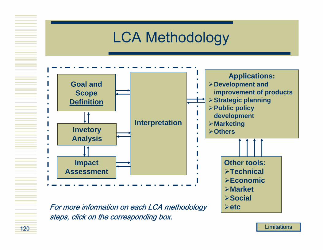
What is LCA
Definitions:A systematic set of procedures for compiling and examining the inputs and outputs of materials and energy and the associated environmental impacts directly attributable to the functioning of a product or service system throughout its life cycle.” (Source: ISO 14040: Life cycle assessment – principles and framework, 1998)
"Life Cycle Assessment is a process to evaluate the environmental burdens associated with a product, process, or activity by identifying and quantifying energy and materials used and wastesreleased to the environment; to assess the impact of those energy and materials used and releases to the environment; and to identify and evaluate opportunities to affect environmental improvements.The assessment includes the entire life cycle of the product, process or activity, encompassing, extracting and processing rawmaterials; manufacturing, transportation and distribution; use, re-use, maintenance; recycling, and final disposal". (Source: Guidelines for Life-Cycle Assessment: A 'Code of Practice', SETAC, Brussels, 1993 )

119
ExampleLife Cycle of Newspaper
Chips
AspenForestry
TMP
Sawmill
DIP
Papermaking
Newspaper
Allocated out of the system
Allocated out of the System
Waste paper
Wood
Water
Air emissions
Transportation
Waste paperManagement
MunicipalLandfill
Wastewater
Solid wastes
Hog fuel
Spruce
Fuel Production
ChemicalProduction
ElectricityProduction
SteamGeneration
LandfillIndustrial
SludgeTreatment
EffluentTreatment
Lumber
Writing
Use phase
Newsprint
120
LCA Methodology
Applications:Development and improvement of productsStrategic planningPublic policy developmentMarketingOthers
Other tools:TechnicalEconomicMarketSocialetc
Goal and Scope
Definition
InvetoryAnalysis
ImpactAssessment
Interpretation
For more information on each LCA methodologysteps, click on the corresponding box.
Limitations

121
Goal and Scope Definition
The goal of an LCA study shall unambiguously state the intended
application, the reasons for carrying out the study and the intended audience, i.e.
to whom the results of the study are intended to be communicated.

122
Goal and Scope Definition
the functions of the product system, or, in the case of comparative studies, the systems ;the functional unit ;the product system to be studied ;the product system boundaries ;allocation procedures ;data requirements ;assumptions ;
types of impact and methodology of impact assessment, and subsequent interpretation to be used ;limitations ;initial data quality requirements ;type of critical review, if any ;type and format of the report required for the study.
The scope of the LCA consists in:
Goal and Scope
Definition
InvetoryAnalysis
ImpactAssessment
Interpretation

123
Function
Definition:Service supplied by a system of product or a processunit.Examples:
Electricity generationSteam productionEtc.
Waste paper valorisationDeinked pulp productionEtc.
Possible functions
CogenerationPaper RecyclingSystem
Return tothe scope

124
Functional Unit
Definition:« Quantified performance of a product system for use as a reference unit in a life cycle assessment study »
Examples:
Electricity generationSteam productionEtc.
Waste paper valorisationDeinked pulp productionEtc.
Possible functions
Generation of 1MW of electricityProduction of 300000 of steam by hour at 125oC and 0.3 MPaEtc.
Recuperation of 1000 kg of waste paperProduction of 1 ton of deinked pulpEtc.
Relatedfunctional unit
CogenerationPaper RecyclingSystem
Return tothe scope

125
Product System
Definition:« Collection of materially andenergetically connectedunit processes whichperforms one or more defined functions »
Unit processA
Unit processB
Unit processC
Product flow
Environment
Environment
Elementary flow
Elementary flow
Elementary flow
Elementary flow
Elementary flow
Elementary flow
Intermediate flow
Intermediate flow
Return tothe scope

126
System Boundaries
Definition:« Interface between a product system and theenvironment or otherproduct systems »
Unit processA
Unit processB
Unit processC
Product flow
Environment
Environment
Elementary flow
Elementary flow
Elementary flow
Elementary flow
Elementary flow
Elementary flow
Intermediate flow
Intermediate flow
System boundaries
Return tothe scope

127
Allocation
Most industrial processes comprise more that one output product, and raw material inputs include intermediate products. These processes are multifunctional.In LCA terms, this means that the product system under system provides more functions than the one related to the functional unit. A decision will have to be taken in order to decide how to split flows and environmental intervention between these functions. This is allocation: “partitioning the input or output flows of a unit process to the product system under study”The allocation procedures must respect the mass conservation rules.The production of by-products as well as the open loop recycling are two common situations implicating allocation.

128
By-Products
Definition:A by-product can be defined as an output which is neither the primary product neither a waste.Example:Suppose you have a system with primary function to produce paper. In this system, you have a unit processwhich is wood sawing and which results in twoproducts, chips and lumber. Only chips will be used in the wood manufacturing, lumber will be sent out of thesystem and use in another one. So, in the system which has as main funtion to produce paper, lumber is a by-product.

129
Open vs. Close-Loop Recycling
Close-loop recycling:The product is reused in thesame product system to producethe same product.
No allocation required!
Close-loop recycling:Recycling of one product from on system to another.
Allocation of environmental impacts and credits of recycling will have to be allocated between both system.
Raw Material
Production
Use
Disposal
Recycling
Raw Material(product 1)
Production(product 1)
Use(produit 1)
Disposal(product 1)
Recycling
Raw Material(product 2)
Production(product 2)
Use(produit 2)
Disposal(product 2)
Return tothe scope

130
Inventory Analysis
Definition:“Phase of life cycle assessment involving the compilation and quantification of inputs and outputs, for a given product system throughout its life cycle”
Goal and Scope
Definition
InvetoryAnalysis
ImpactAssessment
Interpretation
(Source: ISO 14041)
131
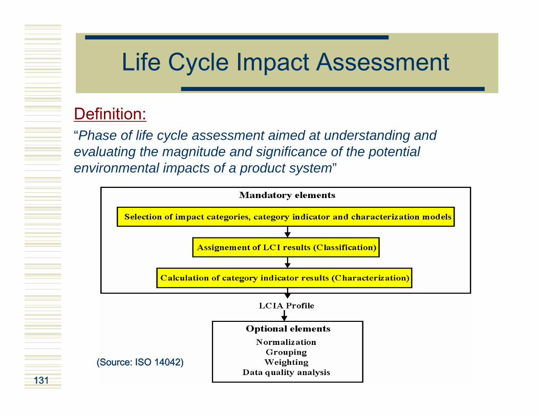
Life Cycle Impact Assessment
Definition:“Phase of life cycle assessment aimed at understanding and evaluating the magnitude and significance of the potential environmental impacts of a product system”
(Source: ISO 14042)

132
From Inventory to Impact Assessment
Inventory Impact
ProductionProcesses
EnergyProduction
WasteDisposal &
Management
Transport
Resource Depletion
Emissions:CFCPbCd
HAPCOVDDTCO2SO2NOX
PDustEtc.
Solid wastes
Resource Depletion
Global WarmingOzone Depletion
EcotoxicologyHuman Health
SmogAcidification
EutrophicationEtc…
Solid Wastes
ResourceDepletion
Mortality andDiceases
EcosystemDepletion
AesthicalValue
SolidWastes
Agre
gate
dIn
dica
tor
Problem Approach“Midpoint”
Damage Approach“Endpoint”
PRECISION Goal and Scope
Definition
InvetoryAnalysis
ImpactAssessment
Interpretation

133
InterpretationDefinition:“Phase of life cycle assessment in which the findings of either the inventory analysis or the impact assessment, or both, are combined consistent with the defined goal and scope in order to reach conclusions and recommendations”
GOAL &SCOPE
LCI
LCIAConclusions
RecommendationsReports
INTERPRÉTATION
Applications
LCA FRAMEW ORK
1. Significant pointsidentification
2. Verification by:- Completeness check- Sensibility check- Coherence check- Others
Goal and Scope
Definition
InvetoryAnalysis
ImpactAssessment
Interpretation
(Source: ISO 14043)

134
LCA Main Limitations
Site-specific impact are not well consideredSteady-state approachLinear modelingBased on a number of technical assumptionsand value choices for instance:
Impact categoriesCharacterization modelsSystem boundariesWeighting of impacts
Availability and reliability of data and models

135
Content
Process SimulationProcess IntegrationMass Integration Energy Integration LCAIntegrating these tools to address MIM

136
In Summary
Minimum Impact Manufacturing aims at minimizing:Resource consumptionEnergy consumptionEnvironmental impact (soil, air and water emissions)
Simulation are useful to better understand the processMass integration is a tool to reduce resource consumption and reject in the environmentEnergy integration is a tool that allows for a better utilization of the energyLCA allows for a holistic evaluation of environmental impacts over the product chain

137
Integration of Tools to Address MIM
MIM is a multi-objective problem involving the best trade-offs between:
Minimum resource consumption;Minimum energy consumption;Minimum air emissions;Minimum water emissions;Minimum solid wastes.
This is also submitted to a lot of complicated constraints:
Process constraints ;Technology constraints;Life cycle interactions;Costs.
For these reasons, integration of PI tools to address MIM is not obvious.

138
References
El-Halwagi, Mahmoud M. Pollution Prevention through Process Integration, Academic Press, San Diego, USA, 1997, 318 p.ISO 1997. Management environnemental – Analyse du cycle de vie Principes et cadres. CAN/CSA-ISO 14040:1997ISO 1998. Management environnemental – Analyse du cycle de vie –Définition de l’objectif et du champ de l’étude et analyse de l’inventaire. CAN/CSA-ISO 14041:1998ISO 2000. Management environnemental – Analyse du cycle de vie –Analyse de l’impact du cycle de vie. CAN/CSA-ISO 14042:2000ISO 2000. Management environnemental – Analyse du cycle de vie – Interprétation du cycle de vie. CAN/CSA-ISO 14043:2000Linnhoff March. 1998. Introduction to Pinch Technology. http://www.linnhoffmarch.com/pdfs/PinchIntro.pdf (page consulted in 2004)


140
Question 1
What is one of the main characteristics of kraft processes?
a) The mechanical pulpb) The necessity to bleach the pulpc) The chemical recovery systemd) Its low water consumption

141
Question 2
Which of the following unit processesgenerates the most sulfur compound emissions?
a) Oxygen delignificationb) Bleachingc) Pulping (digester)d) Recovery furnace

142
Question 3
Toward which of the following elements isMIM oriented?
a) Reducing air emissionsb) Reducing solid wastesc) Maximising shareholder valued) a and be) a, b and c

143
Question 4
Which of these technical problem can beassociated to process closure?
a) Accumulation of undesirable elements in the recovery system
b) Higher cost of utilityc) Higher energy consumptiond) Need of more pulping chemicals

144
Question 5
Which of these tracking model will youuse if one component can be accurately tracked while another one cannot
a) Fixed split modelb) Flow ratio modelc) Species ratio modeld) Degree of freedom equation

145
Question 6
Which of these is not a characteristic of BAT?
a) They must be economically achievableb) They must be process unit orientedc) They must be process orientedd) They must be product oriented

146
Question 7
Which of the following will not decreaseKraft mill energy consumption
a) Water consumption reductionb) Chips screeningc) Less pipingd) Changing ECF bleaching for TCF
bleaching

147
Question 8
Which of the following trade-offs is themost communly associated with energyintegration?
a) Reducing energy while increasing water consumption
b) Capital vs. operating costsc) Energy vs. chemical costsd) Time horizon vs. energy savings

148
Question 9
Which of the following correspond to segregation in mass integration?
a) Avoiding the mixing of the streams.b) Utilization of pollutant-laden stream (a source)
in a process unit (a sink).c) Utilization of separation unit operation to
adjust the composition of the pollution-laden streams to make them acceptable for sinks.
d) Design or operation of changes that alter the flowrate or composition of pollutant-laden streams entering or leaving the process units.

149
Question 10
Which of the following can be describedas a functional unit?
a) The production of kraft pulpb) The production of kraft pulp during 10
hoursc) The production of 1 admt kraft pulp d) b and c