modeling of saturation in induction machines using emtp...
TRANSCRIPT

'-l
ELECTAIC~QWEASIiISTEmSAESEr:1ACH
ELSEVIER Electric Power Systems Research 30 (1994) 279- 285
Modeling of saturation in induction machines using EMTP,PSpice and a dedicated computer program 1:;
J.F. Reynaud, P. PillayDepartment of Electrical Engineering, University of New Orleans, New Orleans, LA 70148, USA
Abstract
The effects of saturation in an induction motor's performance during a direct on-line start are studied using three differenttechniques. In the first method, the motor is modeled using the well-known Electromagnet Transients Program (EMTP) withsaturation included in the magnetizing branch only. Secondly, the motor is modeled using PSpice, a popular circuit simulationsoftware package, where magnetic-core saturation is modeled more accurately than in EMTP. In the final method, the motor ismodeled by taking into account cross- as well as magnetic-core saturation and implemented in a dedicated computer program. Acomparative evaluation of the results is presented.
Keywords: Saturation modeling; Induction motors
1. Introduction
In an industrial environment, it is important to beable to predict, as accurately as possible, the mechanicaland electrical response of electrical machinery underdifferent power supply disturbances. The effects of un-balanced voltages have been well documented in thetechnical literature [I, 2]. Supply short-circuit faultshave been recognized as the cause of severe transients onelectrical machines. Upon reapplication of the supply,even more severe transients can occur, depending on themagnitude and phase of the motor's residual back emf.The current transient could easily exceed even thatproduced at starting, which itself is typically five or sixtimes the rated value. It is during these conditions ofstarting or reconnection of the supply that machinesencounter deep levels of saturation. It then becomesmandatory to accurately model saturation effects for thecorrect determination of motor transients.
In this paper several different methods of model-ing saturation are studied and evaluated, including theuse of EMTP, PSpice, and a dedicated computerprogram.
.. Presented at the Third Biennial Symposium on Industrial Elec-tric Power Applications, New Orleans, LA, USA, November ]992.
Elsevier Science S.A.
SSDI 0378-7796(94 )0086 7-4
2. Induction motor model
2.1. EMTP implementation
The Electromagnetic Transients Program (EMTP) isa powerful software package for the simulation of powersystems. Included in the package is a Universal Machine(UM) model. The model used in EMTP is as follows:
V = Ri + L :t i + Wr Gi (1)where
V=
[
VdS
]
Vdr
Vqs
Vqr [
~dS
]
ldr
lqs
iqr
i=
[R' 0 0 0]
R = 0 Rr 0 0 (2)0 0 Rs 00 0 0 Rr
[L'D
Lmo 0
L]
L= Lmo Lro 0(3)0 0 LsQ
0 0 LmQ LrQ

280 i.F. Reynaud, P. Pil/ay / Electric Power Systems Research 30 (/994) 279-285
r
00
G= 0
-LmQ
0 0
]
LmD LrD
0 0
0 0
000
-LrQ
LsD = Ls + LmD
(4)
(5)
(6)
(7)
LrQ = Lr + LmQ (8)
R is the resistance matrix (constant), LsD and LsQ arethe D and Q axis stator self inductances, LrD and LrQare the D and Q axis rotor self inductances, and Wristhe rotor speed.
JOe electromagnetic torque is defined for both satu-rated and unsaturated conditions as
LSQ = Ls + LmQ
LrD = Lr + LmD
3P
Te = -2"2 Lm(isQirD - isDirq)(9)
dWr
Te = J dt + flwr + 1; (10)
In EMTP, saturation is approximated by a two-seg-ment piecewise curve of the magnetizing characteristicsof the motor (Fig. 1).
During saturation, the inductance matrix L can onlytake two values for Lm. Fig. 2 shows the approximationof the magnetizing curve of the motor by a two-seg-ment piecewise curve. The user must select a point inthe magnetizing curve as the border between saturatedand unsaturated operation. By inspecting this magnetiz-ing curve, it was determined that the motor operates inthe saturated region when 1m> 1.73 A. This point islabeled as PI in Fig. 2.
400
0300
~°...2~... 200
~c:..."::I
100
00 15 205 10
l.Iagnetizing Currenl (A)
Fig. 1. Magnetizing curve.
400
JOO
~"..."
"0
> 200....~uc'""::I
100
00 5 10 15 20
l.Ia9nolizing Curron! (A)
Fig. 2. Approximated magnetizing curve.
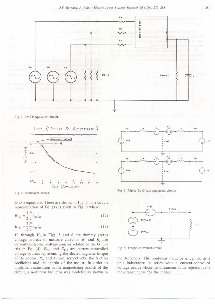
Fig. 3 shows the circuit representation as used inEMTP.
2.2. PSpice implementation
In PSpice, the induction motor is modeled using thesame D, Q axis equations given in Section 2.1. How-ever, saturation is accounted for in the magnetic coremore accurately than in EMTP. A slightly differentform of the torque equation is used in PSpice for easeof implementation:
3P
Te = -2"2(Aqridr - Adriqr)(II)
Aqr= Llriqr + LmQ(iqs+ iqr)
Adr = Llr idr + LmD (idr + id.)
dWr
Te = J dt + flwr + T,
(12)
(13)
(14)
In (12) and (13) LmD and LmQare considered saturableand can be modeled as nonlinear functions of theircurrents. The inductance curve for the motor understudy is approximated by a nonlinear function of themagnetizing currents (Fig. 4):
0.38
LmD = 1+ 0.04662iml + 0.04957( 15)
L - 0.38mQ- I + 0.04662i 2 + 0.04957mq(16)
Since PSpice is a circuit simulation package, anequivalent circuit must be generated to represent the D,
J.F. Reynaud, P. Pillay / Electric Power Systems Research 30 (1994) 279-285
v. Vb Vc
RCnd
Fig. 3. EMTP equivalent circuit.
Lm (True & Approx.)O.!>
0.4~
..,
'C.. 0.3
~.3 0.2
0.1
0.00 2 .. 5 a 10 12
1m (A-rrns)
1.. 15
Fig. 4. Inductance curves.
Q axis equations. These are shown in Fig. 5. The circuitrepresentation of Eq. (1) is given in Fig. 6 where
3P
ETel = "2'2 Adriqr(17)
3P
Ere2 ="2 '2 Aqridr (18)
VI through Vs in Figs. 5 and 6 are dummy (zero)voltage sources to measure currents. E, and E2 arecurrent-controlled voltage sources related to the G ma-trix in Eq. (4). ETel and ETe2 are current-controlledvoltage sources representing the electromagnetic torqueof the motor. Rte and LJ are, respectively, the frictioncoefficient and the inertia of the motor. In order toimplement saturation in the magnetizing branch of thecircuit, a nonlinear inductor was modeled as shown in
281
R.
Rb
AR).fATURE
T
Rc E
Rom.1I
-
Vl E:1Rw Lt.. u,.. R-
Urd
.V3 E2
Rw LI.. LI,.. FIr
Unq
Fig. 5. PSpice D, Q axis equivalent circuits.
V5Ri:e
LJ
-Fig. 6. Torque equivalent circuit.
the Appendix. The nonlinear inductor is defined as aunit inductance in series with a current-controlledvoltage source whose instantaneous value represents theinductance curve for the motor.

282 J.F. Reynaud, P. Pillay / Electric Power Systems Research 30 (/994) 279-285
2.3. Modeling and implementation using a dedicatedprogram
The most'accurate method [3-51 to account for coresaturation is to include cross saturation between the Dand Q axes which is absent under the assumption oflinearity of the magnetic circuit.
Eq. (1) characterizes the induction motor in thesaturated case. In this case the Land G matrices changeto account for the cross-saturation terms:
[
LsD LmD Ldq
L = LmD Lrd Ldq
Ldq Ldq LSQ
Ldq Ldq LmQ
G=
[~
-Lm
Ldq
]
Ldq
LmQ
LrQ
0 0 0
]
0 Lm Lr000
-Lr 0 0
(19)
(20)
The components of Land G are defined as follows:
Lm = I~j (21)
imd imq dLm
Ldq = 1'mI dl'mILr = Lrl+ Lm
I
imd
I
LmD = Lm + -:-- LdqImq
300
250
200
150
az'-'100
Qj='0",..0
~
50
0~ , , h ,~
0 2iJ
Fig. 7. Torque variations for the EMTP unsaturated case.
(22)
(23)
(24)
I
imq
I
LmQ = Lm + -:-- LdqImd
(25)
LsD = LSI + LmD (26)
(27)
(28)
(29)
LsQ = LSI + LmQ
LrD = Lrl + LmD
LrQ = Lrl + LmQ
where Lm is the magnetizing inductance, fm' imd, imq,and 'm are the magnetizing flux linkage, D and Q axismagnetizing currents, and the resultant magnetizingcurrent vector, respectively, and Ldq is the cross-satura-tion inductance.
The flux of the machine can then be expressed interms of the resultant magnetizing current vector asfollows:
t/1m = 0.822 tan-l(0.652Iiml) + 0.0054jiml (30)
The electromagnetic torque is defined for both satu-rated and unsaturated conditions as
3PTe = -- - Lm(isQird - isDirq)22
dWrf3Te=Jd(+ wr+1] (32)
The introduction of the Ldq term in the inductancematrix due to the effects of cross saturation between theD and Q axes induces a much greater computationalburden on the model.
(31)
-10 GO GO
Time (msec)

J.F. Reynaud, P. Pillay / Electric Power Systems Research 30 (1994) 279-285
300 + - -- - - - -+ - -- - - - - - -+-- - - - - -- -+--- - - - - - - -- - -+- - - - - - - - - - - --+I 1I II I1 I1 I, 1I II II II I1 II I
200+ +I II II II II II II II II II II II I
100 + +I I:
\:
I II II . I1 II . II II I1 . 11 I, I
0,.. "''-..j"I' 1, ,+ - - - - - -- -- --- -+ --- -- - - - - - - - -+-- - - - - - - - - - - -+- -- - - - -- - - - - -+- - - - - - - - - - - --+
Oms 20ms 40ms 60ms 80ms lOOmsa v(34)
'"
EZ'"
W
J[jL0I-
Fig. 8. Torque variations for the PSpice unsaturated case.
In order to solve Eq. (1), a fourth-order Runge-Kutta method is used; hence, Eq. (1) is arranged instate space form:
i i = L-I ( V - Ri - w Gi)dt r
dWr = Te - 13wr- r.dt J
3. Results
(33)
(34)
The motor used in the simulation is a four-pole, 5 hpinduction motor with the following parameters:
Rs = 1.86 Q
Rr=2.12Q
Ls = 0.011 H
Lr = 0.006 H
Lm(unsaturated) = 0.40699
J = 0.0625 kg m2fs2
The simulation was carried out at 360 V to empha-size the effects of saturation on the machine perfor-mance. A direct on-line start under this input voltagewas simulated. Figs. 7, 8, and 9 show the results forEMTP, PSpice and the dedicated program, respectively,under linear conditions. It can be seen that all resultsagree as expected. The electric torque reaches about
283
Tim~
300
234
\/"'\I \
I \"~'\\
I \\ .\
\ I\)'-
E168~..::>C"
~102 ,.
36 ~ J/
,
'~""'-----
-300.00 0.01 0.02 0.03 0.04 0.05 0.06 0.07 0.08 0.09 0.10
Time (s)
Fig. 9. Torque variations for the dedicated program unsaturated case,
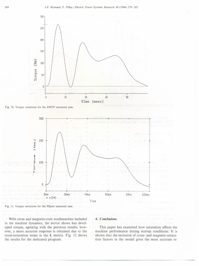
280 N m at startup. When saturation is included,though, the results change. Fig. 10 shows the results forEMTP. It can be seen that torque peaks are reduceddue to the inclusion of saturation in the magnetic core.However, higher torque peaks than the other two casesare observed. This is due to the fact that the magnetiz-ing curve of the machine is approximated in a ratherinaccurate way; thus, the motor operates longer in theunsaturated region, producing higher torque values atstartup. .
The PSpice results (Fig. 11) show the same trend.Torque peaks have decreased even more than in EMTPwhich can be attributed to the more accurate represen-tation of the magnetizing curve of the motor.
284 J.F. Reynaud, P. Pil/ay / Electric Power Systems Research 30 (/994) 279-285
0 'I-" , , ,... .\:), no ,"" no. .no'.. ,
0 20 so10 ro
Time (msec)
Fig. 10. Torque variations for the EMTP saturated case.
300;------ +-- +-------- +------ ---+ ---------t, ,, ,, ,, ,I ,I ,I ,I ,I II I, I, I
... 20C+ +I II ,, ,, ,, ,, II ,I ,I ,I I, II I
100 + +I I, ,, II \ ': .,
~:
I II , ,I II I, . ,, I, ,
0 " . . . . +I II ,+ + + + ~---+
Orns 20ms "Oms 60ms 8!)ms lOOmsD v(34)
EZ'V
~,UL0f-
Fig. 11. Torque variations for the PSpice saturated case.
Time
With cross and magnetic-core nonlinearities includedin the machine dynamics, the motor shows less devel-oped torque, agreeing with the previous results; how-ever, a more accurate response is obtained due to thecross-saturation terms in the L matrix. Fig. 12 showsthe results for the dedicated program.
4. Conclusions
This paper has examined how saturation affects themachine performance during startup conditions. It isshown that the inclusion of cross- and magnetic-satura-tion factors in the model gives the most accurate re-
300
-
;".;0
200
I
,-...a 100z'-'
Q)
C"50I-<
0E-t

J.F. Reynaud, P. Pillay / Electric Power Systems Research 30 (1994) 279-285
300
-300.00 0.01 0.02 0.03 0.04 0.05 0.06 0.07 0.08 0.09 0.1 0
Time (5)
Fig. 12. Torque variations for the dedicated program saturated case.
suIts. Although saturation was only included in the mainflux using a continuous magnetizing curve, the PSpiceresults appear to be more accurate than the resultsobtained using EMTP in which the magnetizing curve ofthe motor is approximated with a two-segment curve.Simulation time is always a constraint that must besatisfied in all computer models. In this respect, EMTPshows the best performance, followed by the dedicatedprogram.
Although it is much simpler to simulate the interactionof the electrical network with the electrical machinery andits loads using an off-the-shelf package such as PSpice orEMTP, it is shown in this paper that a dedicatedcomputer program provides the most accurate results.Furthermore, all models used in this paper are suitablefor the calculation of machine performance in a varietyof situations such as bus transfer and power disturbancestudies.
Acknowledgements
The work reported in this paper was supported by theElectric Power Research Institute, the Entergy Corpora-tion, Louisiana Power and Light Co., and the Mobil OilChalmette Refinery.
285
L
1 H
HL
(v(k)-1)*v( i, j)
Fig. AI. Nonlinear inductor.
Appendix
The model of the nonlinear inductor used to imple-ment saturation in the magnetizing branch is shown inFig. AI, where k is the voltage source node defining LmDor LmQ'
References
[I] J.e. Das, Effects of momentary voltage dips on the operation ofinduction and synchronous motors, IEEE Trans. Ind. Appl., 26(1990) 711-718.
[2] K.J. Sanghani, Protection of large induction motors againstrestarting on out-of-phase power, 2nd Biennial Symp. ElectricIndustry Applications, New Orleans, LA, USA, 1990.
[3] J.E. Brown, K.P. Kovacs and P. Vas, A method of including theeffects of main flux path saturation in the generalized equations ofA.C. machines, IEEE Trans. Power Appar. 3yst., PAS-102 (1983)96-103.
[4] K.-E. Hallenius, P. Vas and J.E. Brown, The analysis of asaturated self-excited asynchronous generator, IEEE Trans. En-ergy Conv., 6 (1991) 336-341.
[5] J.O. Ojo and A. Lipo, An improved model of saturated inductionmachines, IEEE Trans. Ind. Appl., 26 (1990) 212-217.
234 (\
I"'t I \ (\-; I \.......,
102! \ I \I \ j '.......36 / \ / .
! \, .