modeling, identification and feedforward control of...
TRANSCRIPT

Modeling, identification and feedforward control of multivariablehysteresis by combining Bouc-Wen equations and the inverse
multiplicative structure
Didace HABINEZA, Student Member, IEEE,Micky RAKOTONDRABE, Member, IEEE and Yann Le GORREC, Member, IEEE
Abstract— This paper deals with the modeling, identificationand feedforward control of hysteresis found in multi-degrees offreedom (DOF) piezoelectric actuators. One main characteristicof the considered hysteresis behavior is the strong couplings.To express such multivariable hysteresis, we propose to extendthe previous Bouc-Wen hysteresis monovariable model used for1-DOF actuators. Then we propose to combine the resultingmultivariable model with the inverse multiplicative structurein order to derive a multivariable compensator that suppressesthe direct and the coupling hysteresis. Experimental tests on apiezotube scanner demonstrate the efficiency of the proposedapproach.
I. INTRODUCTION
Piezoelectric based actuators are widely used in micro-nano positioning applications thanks to the high resolution,high bandwidth and high stiffness they can offer. However,the accuracy of their operation is compromised by hysteresisnon-linearities [1]. Feedback control can be used to removethe hysteresis effects but, in some applications such asprecise positioning, micromanipulation and microassembly,there is a lack of usable displacements sensors for that.Indeed, embeddable sensors (strain gage...) do not possessthe required performances while performant sensors (opticalsensors...) are very expensive and are bulky [2]. As an al-ternative to feedback control, feedforward control techniqueshave therefore been raised.
The most used feedforward hysteresis compensation ap-proach is the model-based compensation, where hysteresis isfirst modelled. The calculated model is afterwards invertedand put in cascade with the actuator, in order to have a globallinear system. Another approach is charge control basedcompensation where, instead of controlling the actuator bythe voltage, the actuator displacement is controlled by thecharge provided by an electronic circuit [3].
The most used model-based hysteresis models are Preisachand Prandtl-Ishlinskii. They can provide a very high accuracythanks to the superposition of many elementary hysteresisoperators (hysterons) [4][5][11][12]. However, their imple-mentation can become complex if the number of the hys-terons is very high. Furthermore, they are not easy to handlefor structural analysis or synthesis (stability...). Finally, when
FEMTO-ST Institute, AS2M department, Universite de Franche-Comte/CNRS/ENSMM/UTBM, 25000 Besancon, France.
Didace Habineza: [email protected] Rakotondrabe: [email protected] Le Gorrec: [email protected]
the system to be controlled has multiple degrees of freedom(multi-DOF), the number of parameters to be identified withthese models increases exponentially as well as the numberof hysterons, leading to a very complex calculation andimplementation of the compensator. Contrary to that, theBouc-Wen hysteresis model, which is based on a set oftwo equations, can offer a simplicity for handling, structuralanalysis/synthesis and for implementation. As it only usesfour parameters, employing this to multi-DOF actuatorsmay be of interest in term of simplicity, calculation andimplementation.
In [6] hysteresis in multi-DOF systems is studied butfeedback control techniques were used to remove the hys-teresis. In [7][8][9][10] model-based control is used but ithas been combined with feedback to suppress the hysteresis.In addition, couplings and the expected displacements areconsidered separately.
In this paper, we present the feedforward (open-loop) con-trol of hysteresis in multi-DOF piezoactuators by consideringthe direct and the couplings between the axis. Based on theBouc-Wen model used previously for mono-axis actuators,we give an extension to consider multivariable hysteresis.Then, we propose an identification procedure of the pa-rameters and a multivariable compensator to eliminate thehysteresis behaviour and to suppress the couplings betweenthe axis. Finally, experiments on a real system validate theefficiency of the proposed technique.
The paper is organized as follows. In section-II, we remindthe monovariable Bouc-Wen model and we extend it tomultivariable Bouc-Wen hysteresis model. In section-III, aprocedure to identify the parameters of the proposed multi-variable Bouc-Wen hysteresis model is proposed. Section-IVis devoted to the synthesis of a multivariable compensator forthe hysteresis. Finally, section-V presents the experimentscarried out with a multi-DOF piezoelectric actuator (piezo-tube).
II. MUTLIVARIABLE BOUC-WEN HYSTERESIS MODELING
A. Remind of the monovariable Bouc-Wen modeling
Bouc-Wen model of hysteresis has been used in [13](under equations (1)) as a relation between a mechanicalexcitation F , an output displacement y and a state variableh in nonlinear vibrational analysis. The parameters A, Band Γ govern the shape of the hysteresis while the powerm affects the smoothness of the transition from elastic to

plastic response. When the hysteresis is null, i.e. the internalvariable h does not evolve, the Bouc-Wen model becomesa linear relation: y = kF where k is the static gain. Theinfluence (effect) of the different parameters is detailed in[14][15].
{y = kF − hh = AF −B ˙|F |h ˙|h|
m−1− ΓF |h|m
(1)
For piezoelectric actuators where the driving signal is thevoltage, the mechanical excitation F is replaced by inputU . In addition, for piezoelectric based actuators, m canbe assumed to be equal to 1 due to their elastic structure[13]. Consequently, the static Bouc-Wen model adaptedto piezoactuators is described by equation (2) where dprepresents the piezoelectric coefficient, U the input voltageand y, the actuator deflection [1]. figure-1a depicts the blockdiagram of this Bouc-Wen model.
{y(t) = dpU(t)− h(t) , y(t0) = y0
h(t) = AU(t)−B|U(t)|h(t)− ΓU(t)|h(t)| , h(t0) = h0
(2)The previous Bouc-Wen expression can be reduced to
(3) by writing h = H(U) where H(U) is a nonlinearoperator characterized by the second equation of (2). Thewriting proposed in equation (3) is easier to handle whensynthesizing a feedforward hysteresis compensator [1].
y = dpU −H(U) (3)
B. Extension to multivariable modeling
The existing Bouc-Wen model as described by equation(2) is used for monovariable hysteresis modeling and com-pensation. This cannot be used to model and then to calculatea compensator for actuators having multiple degrees offreedom. In this section, we propose to extend this monovari-able model into multivariable Bouc-Wen hysteresis modelwith n inputs and n outputs. The corresponding diagramis represented in figure-1b where an input vector U =(U1 U2 · · ·Un)T and an output vector y = (y1 y2 · · · yn)T
are used.To perform, let the following tensorial expression be the
extension of the monovariable model of (2):
y1
y2
...yn
︸ ︷︷ ︸
y
=
D11 D12 · · · D1n
D21 D22 · · · D2n
......
...Dn1 Dn2 · · · Dnn
︸ ︷︷ ︸
Dp
U1
U2
...Un
︸ ︷︷ ︸
U
−
h1
h2
...hn
︸ ︷︷ ︸
h
(4)
h1
h2
...hn
︸ ︷︷ ︸
h
=
A11 A12 · · · A1n
A21 A22 · · · A2n
......
...An1 An2 · · · Ann
︸ ︷︷ ︸
A
U1
U2
...Un
︸ ︷︷ ︸
U
−
B11 B12 · · · B1n
B21 B22 · · · B2n
......
...Bn1 Bn2 · · · Bnn
︸ ︷︷ ︸
B
|U1| 0
|U2|. . .
0 |Un|
︸ ︷︷ ︸
diag(|U |)
h1
h2
...hn
︸ ︷︷ ︸
h
−
Γ11 Γ12 · · · Γ1n
Γ21 Γ22 · · · Γ2n
......
...Γn1 Γn2 · · · Γnn
︸ ︷︷ ︸
Γ
U1 0
U2
. . .
0 Un
︸ ︷︷ ︸
diag(U)
|h1||h2|
...|hn|
︸ ︷︷ ︸|h|
(5)
i.e.
{y = DpU − hh = AU −Bdiag
(|U |)h− Γdiag
(U)|h|
(6)
where h ∈ Rn is a state vector and A ∈ Rn×n,B ∈ Rn×n and Γ ∈ Rn×n are the matricial parametersof the multivariable Bouc-Wen hysteresis model. In the nextsection, we propose a method to identify these parametersfrom experimental data.
III. IDENTIFICATION OF THE MULTIVARIABLEBOUC-WEN HYSETERESIS MODEL
Equations (4) and (5) can be developped and written as:yi =
(n∑
j=1
DijUj
)− hi
hi =n∑
j=1
AijUj −n∑
j=1
Bij |Uj |hj −n∑
j=1
ΓijUj |hj |(7)
The parameters to be identified are Dij , Aij , Bij and Γij
(1 ≤ i, j ≤ n) which are respectively the elements of thematrices Dp, A, B and Γ of equation (5). The subscript idenotes the considered output inside the vector y, while j theconsidered input inside the vector U . We notice that wheni = j, we have the direct hysteresis and when i 6= j, wehave the coupling hysteresis.
From the second equation of (7), we remark that all signalshi (1 ≤ i ≤ n) do not depend on hi but on hj (with jthe subscript denoting the applied U ). This means that foreach applied voltage Uj (1 ≤ j ≤ n), all the outputs yi(1 ≤ i ≤ n) which, naturally, depends on hi also dependson hj . So, the identification procedure follows the followingsteps:
Step 1 (experimental characterization): Apply a repet-itive (sinusoidal or triangular) voltage input Uj (starting byj = 1) to the system and leave all the remaining inputs (i.e.all Uk with k 6= j and 1 ≤ k ≤ n) equal to zero. Capture all
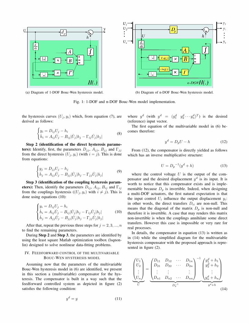
(a) Diagram of 1-DOF Bouc-Wen hysteresis model. (b) Diagram of n-DOF Bouc-Wen hysteresis model.
Fig. 1: 1-DOF and n-DOF Bouc-Wen model implementation.
the hysteresis curves (Uj , yi) which, from equation (7), arederived as follows:{
yi = DijUj − hihi = AijUj −Bij |Uj |hj − ΓijUj |hj |
(8)
Step 2 (identification of the direct hysteresis parame-ters): Identify, first, the parameters Djj , Ajj , Bjj and Γjj
from the direct hysteresis (Uj , yi) (with i = j). This is donefrom equations:{
yj = DjjUj − hjhj = AjjUj −Bjj |Uj |hj − ΓjjUj |hj |
(9)
Step 3 (identification of the coupling hysteresis param-eters): Then, identify the parameters Dij , Aij , Bij and Γij
from the couplings hysteresis ((Uj , yi) with i 6= j). This isdone using equations (10):
yi = DijUj − hihi = AijUj −Bij |Uj |hj − ΓijUj |hj |hj = AjjUj −Bjj |Uj |hj − ΓjjUj |hj |
(10)
After that, repeat the previous three steps for j = 2, 3, ..., nto find the remaining parameters.
During Step 2 and Step 3, the parameters are identified byusing the least square Matlab optimization toolbox (lsqnon-lin) designed to solve nonlinear data-fitting problems.
IV. FEEDFORWARD CONTROL OF THE MULTIVARIABLEBOUC-WEN HYSTERESIS MODEL
Assuming now that the parameters of the multivariableBouc-Wen hysteresis model in (6) are identified, we presentin this section a (multivariable) compensator for the hys-teresis. The compensator is built in a way such that thefeedforward controlled system as depicted in figure (2)satisfies the following condition:
yd = y (11)
where yd (with yd = (yd1 yd2 · · · ydn)T ) is the desired(reference) input vector.
The first equation of the multivariable model in (6) be-comes therefore:
yd = DpU − h (12)
From (12), the compensator is directly yielded as followswhich has an inverse multiplicative structure:
U = Dp−1(yd + h) (13)
where the control voltage U is the output of the com-pensator and the desired displacement yd is its input. It isworth to notice that this compensator exists and is imple-mentable because Dp is invertible. Indeed, when designinga multi-DOF actuators, the first natural expectation is thatthe input control Ui influence the output displacement yi:in other words, the direct transfers Dii are non-null. Thismeans that the diagonal of the matrix Dp is non-null andtherefore it is invertible. A case that may renders this matrixnon-invertible is when the couplings annihilate some directtransfers. However this case is impossible or very rare forreal processes.
In details, the compensator in equation (13) is written asin (14) while the simplified diagram for the multivariablehysteresis compensator with the proposed approach is repre-sented in figure (2).
U1
U2
...Un
︸ ︷︷ ︸
U
=
D11 D12 · · · D1n
D21 D22 · · · D2n
......
...Dn1 Dn2 · · · Dnn
−1
︸ ︷︷ ︸D−1
p
yd1 + h1
yd2 + h2
...ydn + hn
︸ ︷︷ ︸
yd+h
(14)

Fig. 2: n-DOF hysteresis compensator diagram.
The proposed approach is devoted to multi-DOF actuators.Another advantage is that there is no additional calculationto derive the compensator, except the inversion of Dp. Assoon as the model is identified, the compensator is derivedthanks to the inverse multiplicative structure.
V. EXPERIMENTAL RESULTS AND DISCUSSIONS
A. Experimental setup
The actuator used for the experiments is a PT230.94piezotube scanner (from PIceramic company) that is oftenused in atomic force microscopy (AFM). This is an actuatordesigned to provide deflections along with three directions(X, Y and Z). The actuator is made up of PZT material (leadzirconate titanate), four external electrodes (+x, -x, +y and-y), and an inside electrode for ground (see figure (3)). +Uand −U voltages can be applied on +x and -x electrodes(+y and -y respectively) to obtain tube deflections along theX direction (Y direction). Axial deformation (extension orelongation along the Z direction) is obtained by applyingsimultaneously +U on the four external electrodes.
As the PT230.94 operating voltage range is ±250V , ahigh voltage amplifier is needed to amplify the controlvoltage. The tube deflections are measured by using opticaldisplacement sensors (KC2420 from Keyence company). Thesensors are set to have a resolution of 50nm, an accuracy of200nm and a bandwidth in excess of 1500kHz. The sensorsand the amplifier are connected to the computer through a1103-dSPACE board (Figure (4)).
Due to the tubular shape of the actuator, it does not allowlinear measurement with the optical displacement sensors.For this reason, we placed a small cube on the top ofthe piezotube with perpendicular sides pointing towardsthe sensors. Also, in the sequel, we are interested to thehysteresis behavior along the X and the Y axis and to theircontrol. Accounting the general case where we are face tocouplings, we can consider a bi-variable system with inputsUx and Uy and with outputs X and Y .
B. System characterization, modeling and identification
This section is devoted to the characterization andmodeling of the piezotube and the parameters identification.
• Multivariable Hysteresis Characterization:We apply first a sine voltage Ux with an amplitude of200V and a frequency of 0.1Hz to the x electrodes
Fig. 3: (a) Top view showing the tube with its five electrodes(four external and one ground electrodes), (b) the tubebending in X and Y directions, (c) side view of the tubeand its elongation in Z direction.
Fig. 4: Experimental setup description.
(+x and -x) and we let Uy be zero. The correspondingdisplacements X and Y are pictured respectively infigure (5 - (a) and (c)). Figure (5 - (a)) correspondsto the direct hysteresis along X axis while Figure (5 -(c)) corresponds to the coupling along Y axis due toUx.Then, Ux is set equal to zero and we apply the same sinevoltage but to the y electrodes (+y and -y). The captured

deflections X and Y are represented in figure (5 - (b)and (d)). Figure (5 - (b)) corresponds to the couplinghysteresis along X axis due to Uy while Figure (5 - (d))corresponds to the direct hysteresis along Y axis.
Fig. 5: Hysteresis Characterization: (a) and (c) represent Xand Y displacements when only Ux is applied (Uy = 0), and(b) and (d) when only Uy is applied (Ux = 0). (a) and (d)represent the direct hysteresis, and (b) and (d) represent thecouplings.
Notice that the chosen frequency (0.1Hz) used for thecharacterization and identification corresponds to theoperational frequency when controlling the system.
• Bouc-Wen parameters Identification and Validation:This is done by following the steps discussed in sectionIII. After obtaining the experimental hysteresis curves,we have identified the parameters of the multivariableBouc-Wen model that fits with the experimental databy following these steps. The identified parameters arepresented in table (I).
TABLE I: 2-DOF multivariable Hysteresis Bouc-Wen modelparameters
UxX UxY UyX UyYdp 0.2042 0.0131 -0.0264 0.1930A 0.0857 0.0032 -0.0086 0.0780B 0.0072 0.0008 -0.0012 0.0100Γ 0.0023 -0.0003 -0.0003 -0.0008
We mention that the model parameters are identified onlyfrom the external hysteresis loops, i.e from the hysteresisloops captured when the input voltage amplitude is in itsmaximal operating range (±200V ). Figures (6 - (a) to (d))picture the comparison between the experimental hysteresisand the simulation of the identified model.
To validate the identified model, experiments and modelsimulation with lower input control voltages have also been
Fig. 6: Experimental curves and the simulation of the iden-tified 2-DOF Bouc-Wen model.
Fig. 7: Model validation: experimental curves and the simu-lation of the identified 2-DoF Bouc-Wen model with internalhysteresis loops (input voltages ±100V ).
carried out. In figure (7), hysteresis with the external loopsand hysteresis obtained with ±100V input voltage are plot-ted.
The comparison in figures (6) and (7) shows the goodconveniency of the identified model. We remark however thatthe model of the couplings presents slight difference relativeto the experiments. This is due to the fact that Bouc-Wenmodel only captures symmetric hysteresis.

C. Hysteresis compensation and experimental results
After the model identification and validation, we haveimplemented in Simulink-Matlab software the hysteresiscompensator of figure (2). The compensator is built byusing the parameters identified in section V-B. The actuatordeflections, when controlled, with respect to the desired inputcommands, are represented in figure (8).
Fig. 8: Tube deflections after compensation. Xd and Yd areapplied separately. (a) and (d) show the expected deflections,and (b) and (c), the system couplings after compensation.
Fig. 9: Evaluation of tracking error with sinusoidal inputs,for expected deflections. Xd and Yd are applied separately.
Comparing the initial hysteresis figures (5) with the resultsin (8) obtained with the compensator, we can clearly see that
the proposed compensator has almost suppressed hysteresisand reduced considerably the coupling amplitudes.
Figure (9) shows the tracking of sine input references Xd
and Yd, for expected deflections. It can be seen that, with theproposed compensator, the tracking error is less than 3µmalong X and 2.5µm along Y axis.
We conclude from these figures that the input-outputmap between the desired displacements and the real outputdisplacements reaches the expected linear behavior withunitary gain. Furthermore, the couplings are reduced to lessthan 3.3% of the amplitude of the desired displacements: lessthan 2µm of coupling for 60µm of desired displacements.
D. Complex trajectories tracking
In this subsection, we use a complex trajectory to thecontrolled piezotube. This has been done by tracking a circlewith a radius of 20µm in X-Y plane. Figure (10) pictures theresults obtained with compensator and without compensator(scaled for the comparison). From this figure, we noticethe improvement of the circular contouring when using thehysteresis compensator, i.e. the shape of the circle moreregular. In addition, the accuracy is improved thanks to thehysteresis compensator.
Fig. 10: Comparison between compensated and uncompen-sated system responses, by tracking a Circular Contour.
VI. CONCLUSIONS
In this paper, we presented the characterization, modeling,identification and feedforward compensation of hysteresis inmulti-DOF piezoactuators. First, we proposed to model themultivariable hysteresis by extending the existing monovari-able hysteresis into matricial model. The model permittedto account not only the hysteresis nonlinearities but also thecouplings between the axis. Then, an appropriate identifi-cation procedure was proposed. The compensation is basedon the combination of the yielded multivariable model andthe inverse multiplicative structure. Two major advantagesof the proposed compensator are its existence ensured andthe fact that no additional calculation is required to deriveit. As soon as the model is identified, the compensatoris derived. Experimental tests with a piezoelectric tube(piezotube) working on 2-DOF have been carried out. Theexperiments, performed with classical signals and with morecomplex trajectory (circular), demonstrated the efficiencyof the proposed modeling, identification and compensationtechniques.

ACKNOWLEDGMENT
This work is supported by the national ANR-JCJC C-MUMS-project (National young investigator project ANR-12-JS03007.01: Control of Multivariable Piezoelectric Mi-crosystems with Minimization of Sensors). A part of thiswork has also been supported by the national ANR-Emergence MYMESYS-project (ANR-11-EMMA-006: HighPerformances Embedded Measurement Systems for multiDe-grees of Freedom Microsystems).
REFERENCES
[1] Rakotondrabe, Micky, ”Bouc-Wen modeling and inverse multiplicativestructure to compensate hysteresis nonlinearity in piezoelectric actu-ators”, IEEE Transactions on Automation Science and Engineering,pp.428-431 Vol.8, 2011
[2] Devasia, Santosh and Eleftheriou, Evangelos and Moheimani, SOReza, ”A survey of Control Issues in Nanopositioning”, IEEE Trans-actions on Control Systems Technology,pp.802-823 Vol.15, 2007
[3] Clayton, GM and Tien, S and Fleming, AJ and Moheimani, SOR andDevasia, S, ”Hysteresis and vibration compensation in piezoelectricactuators by integrating charge control and inverse feedforward”, 4thIFAC Symp. Mechatron. Syst., Heidelberg, Germany, 2006
[4] Kuhnen, Klaus and Janocha, Hartmut, ”Inverse feedforward controllerfor complex hysteretic nonlinearities in smart-material systems”, Con-trol Intelligent Systems,pp.74-83 Vol.29, 2001
[5] R. V. Iyer, X. Tan, P. S. Krishnaprasad, ”Approximate inversion ofthe Preisach hysteresis operator with application to control of smartactuators”, IEEE Transactions on Automatic Control, vol. 50, no. 6,pp. 798-810, 2005
[6] Merry, Roel and Uyanik, Mustafa and van de Molengraft, Rene andKoops, Richard and van Veghel, Marijn and Steinbuch, Maarten,”Identification, control and hysteresis compensation of a 3 DOFmetrological AFM”, Asian Journal of Control, pp.130–143 Vol.11,2009
[7] Yong, Yuen Kuan and Aphale, Sumeet S and Moheimani, SO Reza,”Design, identification, and control of a flexure-based XY stage forfast nanoscale positioning”, IEEE Transactions on Nanotechnology,pp.46 Vol.8, 2009
[8] Rakotondrabe, Micky and Agnus, Joel and Lutz, Philippe, ”Feedfor-ward and IMC-feedback control of a nonlinear 2-DOF piezoactuatordedicated to automated tasks”, IEEE Conference on Automation Sci-ence and Engineering, pp.393–398, 2011
[9] Micky Rakotondrabe and Kanty Rabenorosoa and Joel Agnus andNicolas Chaillet, ”Robust Feedforward-Feedback Control of a Non-linear and Oscillating 2-DOF Piezocantilever”, IEEE T. AutomationScience and Engineering, pp.506–519 Vol.8, 2011
[10] Xu, Qingsong and Li, Yangmin, ”Dahl model-based hysteresis com-pensation and precise positioning control of an XY parallel microma-nipulator with piezoelectric actuation”, Journal of dynamic systems,measurement, and control, pp.041011 Vol.132, 2010
[11] Al Janaideh, Mohammad and Su, Chun-Yi and Rakheja, Subhash,”Compensation of rate-dependent hysteresis nonlinearities in a piezomicro-positioning stage”, International Conference on Robotics andAutomation (ICRA), pp.512–517, 2010
[12] Ang, Wei Tech and Khosla, Pradeep K and Riviere, Cameron N,”Feedforward controller with inverse rate-dependent model for piezo-electric actuators in trajectory-tracking applications”, Transactions onMechatronics, IEEE/ASME, pp.134–142 Vol.12, 2007
[13] Low, TS and Guo, W, ”Modeling of a three-layer piezoelectricbimorph beam with hysteresis”, Journal of MicroelectromechanicalSystems,pp.230-237 Vol.4, 1995
[14] W.Schwanen, ”Modelling and Identification of the dynamic behaviorof a wire rope spring”, Technische Universiteit Eindhoven, 2004
[15] Sain, Patrick M and Sain, Michael K and Spencer, BF, ”Models forHysteresis and Application to Structural Control”, American ControlConference, 1997
[16] Rakotondrabe, Micky, ”Classical Prandtl-Ishlinskii modeling and in-verse multiplicative structure to compensate hysteresis in piezoactua-tors”, American Control Conference, pp.1646-1651 Vol.10, 2012