miniature branch circuit breakers miniature supplementary
TRANSCRIPT

Close Protection from Moeller
miniature branch circuit breakersminiature supplementary protectors


FAZ branch circuit breakersGeneral Information ................................................................. 2
Selection Tables Trip Characteristic C - Box terminals ................................ 4
Trip Characteristic D - Box terminals ............................... 5
Trip Characteristic C - Ring tongue terminals ................ 6
Trip Characteristic D - Ring tongue terminals ............... 7
Accessories .................................................................................. 8
Technical Data ........................................................................... 10
Dimensions ................................................................................. 15
FAZ supplementary protectorsGeneral Information ................................................................. 20
Selection Tables Trip Characteristic B ............................................................. 22
Trip Characteristic C ............................................................. 24
Trip Characteristic D ............................................................ 26
Trip Characteristic K ............................................................. 28
Trip Characteristic Z ............................................................. 30
Trip Characteristic S ............................................................. 31
Accessories .................................................................................. 32
Technical Data ........................................................................... 35
Dimensions ................................................................................. 41
MCB ApplicationsApplying branch circuit breakers and supplementary protectors in North America ..................... 43

�
R
series FAZ branch circuit breakersBranch circuit protection up to 10kA
> Molded case circuit breaker per UL 489 / CSA 22.2 No. 5.1
> Current limiting device
> Ring-tongue terminals available
> Worldwide approvals
Moeller has just expanded its FAZ line of miniature circuit breakers to include de-vices that are listed and certified as molded case circuit breakers per UL 489 and CSA 22.2, No. 5-02. These new branch circuit breakers, called FAZ-NA, are ideal for the protection of power supplies, control power transformers, HVAC, refrigeration equipment, florescent lighting (to 20A) and many other applications requiring a primary protective device.
Flexible product rangeMoeller’s FAZ Branch Circuit Breakers are available in one, two and three pole con-figurations with 20 different current ratings ranging from 0.5A to 40A. All breakers are available in both C and D tripping curves, offering protection from 5 to 10 and 10 to 20 x the continuous rating of the device (In). Two and three pole devices can be used in solidly grounded circuits up to 480V AC. The entire line offers short circuit ratings of 10kA regardless of voltage applied.
Many installation optionsFAZ Branch Circuit Breakers are available in two terminal configu-rations; standard box terminals that accept multiple conductors and ring-tongue terminals, ideally suited to the demanding re-quirements of the semi-conductor industry. All breakers mount on standard 35mm DIN-rail. Bus Connectors and Feeder Termi-nals facilitate mounting and wiring of multiple miniature circuit breaker arrays in control panel assemblies. Power to the circuit breakers can also be fed from the line or load side.
Standard features enhance safetyAs with most products from Moeller, FAZ breaker terminals provide finger and back-of-hand protection to guard against accidental contact with live parts. A color-cod-ed red/green indicator provides immediate visual indication of device status and isolation function (green for OFF, red for ON). All FAZ breakers incorporate a “trip-free” mechanism. This prevents the trip function from being defeated by holding the operator in the ON position. In addition, all FAZ branch circuit breakers are UL listed and CSA certified for fuseless protection of smaller AWG 18 and 16 conductors!
Worldwide acceptanceFAZ-NA (RT) Molded Case Circuit Breakers are UL Listed for use in the United States in accordance with NFPA 70 (NEC). The devices comply with UL 489 and CSA 22.2 No. 5-02, meeting the requirements for Molded Case Circuit Breakers. These de-vices also comply with IEC 60947-2 and are CE compliant.
See page 43 about…
Applying
in North America
FAZ
(appphoto)

�
This graph shows trip-time versus over-current for Type C and D devices FAZ-NA branch circuit breakers.
0.0005
Trip
pin
gtim
et
[sec
]
7200
3600
1200
600
300
120
60
30
10
5
2
1
0.5
0.2
0.1
0.05
0.02
0.005
0.01
0.002
0.001
504030201510987654321
acc. to IEC 60898-1instantaneous tripping
5454
3
12
N
N
1
2
t
nt
N
N
N
N
4
6
N3
I = 1.0 I (T=40 °C )
I = 1.35 I : t < 1 h (T=25 °C )
2.0 I : t = 12- 120 s (T=25 °C )
10 I : t < 0.1 s
20 I : t < 0.1 s
conventional non-tripping current
conventional tripping current
type C: 5 I : t > 0.1 s
type D: 10 I : t > 0.1 s
tripping characteristicacc. to UL 489 / CSA 22.2 No. 235
3
DC
Multiples of In
Tripping characteristicsMoeller FAZ-NA(RT) branch circuit breakers are avail-able with “C” and “D” tripping characteristics. C-curve devices are suitable for applications where medium levels of inrush current are expected. Applications in-clude small transformers, lighting, pilot devices, con-trol circuits, and coils. C-curve devices provide a me-dium magnetic trip point.
Devices with a “D” curve are suitable for applications where high levels of inrush current are expected. The high magnetic trip point prevents nuisance tripping in high inductive applications such as motors, transform-ers, and power supplies.
Even though not required by NEC or CEC for Branch Circuit Breakers, Moeller’s FAZ-NA(RT) devices are cur-rent limiting, which means they interrupt fault currents within one half cycle of the fault. Current limiting de-vices offer superior protection by reducing peak let-through current and energy.
Available in one, two and three poles with “C” & “D” trip characteristics
Arc Chutes quickly extinguish arcs generated by the opening of the
contacts under normal or high fault conditions
Arc chutes and switching mechanism are kept apart for mechanical
reliability
Breakers install on standard DIN-rail
Bimetal trip assembly provides reliable overload protection through a broad
range of ambient temperatures
Short circuit rating to 10kA (@277V AC and 480Y/277V AC for multi-pole) –
Choose box terminals (AWA #18 to #4 ) or terminals for ring-tongue connectors
Complete bus bar system available for quickly installing breaker arrays
Trip-free design; breaker cannot be defeated by holding the handle in the ON position
Color coded indicator provides breaker status for easy troubleshooting
Breaker information printed on the front of the device for quick identification
Discover these advanced features

� moellerNA.com FAZ-CAT-NA-1107 Discount Schedule B��
> UL Approved (UL489) and CSA Certified (CSA C22.2 No. 5-02) as Branch Circuit Breakers
> Interrupting capacity: 10kA UL/CSA; 15kA IEC 60947
> Trip characteristic C: Response time of instantaneous trip: 5 – 10 x In current rating
> Current limiting device
Type C CharacteristicsSuitable for applications where medium levels of inrush current are expected. Instantaneous trip is 5 to 10 x rating of device (In). Applica-tions include small transformers, lighting, pilot devices, control circuits, and coils. Medium magnetic trip point.
Trip Characteristic C – Designed for inductive loads
Rated Current
In[A]
1 pole 2 poles 3 poles
Catalog Number Price Catalog Number Price Catalog Number Price0.5 FAZ-CO,5/1-NA 39 FAZ-C0,5/2-NA 90 FAZ-C0,5/3-NA 137
1 FAZ-C1/1-NA 39 FAZ-C1/2-NA 90 FAZ-C1/3-NA 137
1.5 FAZ-C1,5/1-NA 39 FAZ-C1,5/2-NA 90 FAZ-C1,5/3-NA 137
2 FAZ-C2/1-NA 39 FAZ-C2/2-NA 90 FAZ-C2/3-NA 137
3 FAZ-C3/1-NA 39 FAZ-C3/2-NA 90 FAZ-C3/3-NA 137
4 FAZ-C4/1-NA 39 FAZ-C4/2-NA 90 FAZ-C4/3-NA 137
5 FAZ-C5/1-NA 39 FAZ-C5/2-NA 90 FAZ-C5/3-NA 137
6 FAZ-C6/1-NA 34 FAZ-C6/2-NA 78 FAZ-C6/3-NA 120
7 FAZ-C7/1-NA 34 FAZ-C7/2-NA 78 FAZ-C7/3-NA 120
8 FAZ-C8/1-NA 34 FAZ-C8/2-NA 78 FAZ-C8/3-NA 120
10 FAZ-C10/1-NA 34 FAZ-C10/2-NA 78 FAZ-C10/3-NA 120
13 FAZ-C13/1-NA 34 FAZ-C13/2-NA 78 FAZ-C13/3-NA 120
15 FAZ-C15/1-NA 34 FAZ-C15/2-NA 78 FAZ-C15/3-NA 120
16 FAZ-C16/1-NA 34 FAZ-C16/2-NA 78 FAZ-C16/3-NA 120
20 FAZ-C20/1-NA 34 FAZ-C20/2-NA 78 FAZ-C20/3-NA 120
25 FAZ-C25/1-NA 34 FAZ-C25/2-NA 78 FAZ-C25/3-NA 120
30 FAZ-C30/1-NA 34 FAZ-C30/2-NA 78 FAZ-C30/3-NA 120
32 FAZ-C32/1-NA 34 FAZ-C32/2-NA 78 FAZ-C32/3-NA 120
35 FAZ-C35/1-NA 34 FAZ-C35/2-NA 78 FAZ-C35/3-NA 120
40 FAZ-C40/1-NA 34 FAZ-C40/2-NA 78 FAZ-C40/3-NA 120
See Trip Curve chart on page 11
FAZ Branch Circuit Breakers
TripCharacteristicC

FAZ-CAT-NA-1107 moellerNA.com � Discount Schedule B��
> UL Approved (UL489) and CSA Certified (CSA C22.2 No. 5-02) as Branch Circuit Breakers
> Interrupting capacity: 10kA UL/CSA; 15kA IEC 60947
> Trip characteristic D: Response time of instantaneous trip: 10 – 20 x In current rating
> Current limiting device
Type D CharacteristicsSuitable for applications where high levels of inrush current are expected. Instantaneous trip is 10 to 20 x rating of device (In). The high magnetic trip point prevents nuisance tripping in high inductive ap-plications such as motors, transformers, and power supplies.
Trip Characteristic D – Designed for highly inductive loads
Rated Current
In[A]
1 pole 2 poles 3 poles
Catalog Number Price Catalog Number Price Catalog Number Price0.5 FAZ-D0,5/1-NA 45 FAZ-D0,5/2-NA 103 FAZ-D0,5/3-NA 158
1 FAZ-D1/1-NA 45 FAZ-D1/2-NA 103 FAZ-D1/3-NA 158
1.5 FAZ-D1,5/1-NA 45 FAZ-D1,5/2-NA 103 FAZ-D1,5/3-NA 158
2 FAZ-D2/1-NA 45 FAZ-D2/2-NA 103 FAZ-D2/3-NA 158
3 FAZ-D3/1-NA 45 FAZ-D3/2-NA 103 FAZ-D3/3-NA 158
4 FAZ-D4/1-NA 45 FAZ-D4/2-NA 103 FAZ-D4/3-NA 158
5 FAZ-D5/1-NA 45 FAZ-D5/2-NA 103 FAZ-D5/3-NA 158
6 FAZ-D6/1-NA 39 FAZ-D6/2-NA 90 FAZ-D6/3-NA 138
7 FAZ-D7/1-NA 39 FAZ-D7/2-NA 90 FAZ-D7/3-NA 138
8 FAZ-D8/1-NA 39 FAZ-D8/2-NA 90 FAZ-D8/3-NA 138
10 FAZ-D10/1-NA 39 FAZ-D10/2-NA 90 FAZ-D10/3-NA 138
13 FAZ-D13/1-NA 39 FAZ-D13/2-NA 90 FAZ-D13/3-NA 138
15 FAZ-D15/1-NA 39 FAZ-D15/2-NA 90 FAZ-D15/3-NA 138
16 FAZ-D16/1-NA 39 FAZ-D16/2-NA 90 FAZ-D16/3-NA 138
20 FAZ-D20/1-NA 39 FAZ-D20/2-NA 90 FAZ-D20/3-NA 138
25 FAZ-D25/1-NA 39 FAZ-D25/2-NA 90 FAZ-D25/3-NA 138
30 FAZ-D30/1-NA 39 FAZ-D30/2-NA 90 FAZ-D30/3-NA 138
32 FAZ-D32/1-NA 39 FAZ-D32/2-NA 90 FAZ-D32/3-NA 138
35 FAZ-D35/1-NA 39 FAZ-D35/2-NA 90 FAZ-D35/3-NA 138
40 FAZ-D40/1-NA 39 FAZ-D40/2-NA 90 FAZ-D40/3-NA 138
See Trip Curve chart on page 11
FAZ Branch Circuit Breakers
TripCharacteristicD

� moellerNA.com FAZ-CAT-NA-1107 Discount Schedule B��
> UL Approved (UL489) and CSA Certified (CSA C22.2 No. 5-02) as Branch Circuit Breakers
> Connections for ring-tongue terminals
> Trip characteristic C: Response time of instantaneous trip: 5 – 10 x In current rating
> Interrupting capacity: 10kA UL/CSA; 15kA IEC 60947
Type C CharacteristicsSuitable for applications where medium levels of inrush current are expected. Instantaneous trip is 5 to 10 x rating of device (In). Applica-tions include small transformers, lighting, pilot devices, control circuits, and coils. Medium magnetic trip point.
Ring Tongue Trip Characteristic C – Designed for inductive loads
Rated Current
In[A]
Ring Tongue 1 pole Ring Tongue 2 poles Ring Tongue 3 poles
Catalog Number Price Catalog Number Price Catalog Number Price0.5 FAZ-CO,5/1-RT 44 FAZ-C0,5/2-RT 100 FAZ-C0,5/3-RT 152
1 FAZ-C1/1-RT 44 FAZ-C1/2-RT 100 FAZ-C1/3-RT 152
1.5 FAZ-C1,5/1-RT 44 FAZ-C1,5/2-RT 100 FAZ-C1,5/3-RT 152
2 FAZ-C2/1-RT 44 FAZ-C2/2-RT 100 FAZ-C2/3-RT 152
3 FAZ-C3/1-RT 44 FAZ-C3/2-RT 100 FAZ-C3/3-RT 152
4 FAZ-C4/1-RT 44 FAZ-C4/2-RT 100 FAZ-C4/3-RT 152
5 FAZ-C5/1-RT 44 FAZ-C5/2-RT 100 FAZ-C5/3-RT 152
6 FAZ-C6/1-RT 38 FAZ-C6/2-RT 86 FAZ-C6/3-RT 132
7 FAZ-C7/1-RT 38 FAZ-C7/2-RT 86 FAZ-C7/3-RT 132
8 FAZ-C8/1-RT 38 FAZ-C8/2-RT 86 FAZ-C8/3-RT 132
10 FAZ-C10/1-RT 38 FAZ-C10/2-RT 86 FAZ-C10/3-RT 132
13 FAZ-C13/1-RT 38 FAZ-C13/2-RT 86 FAZ-C13/3-RT 132
15 FAZ-C15/1-RT 38 FAZ-C15/2-RT 86 FAZ-C15/3-RT 132
16 FAZ-C16/1-RT 38 FAZ-C16/2-RT 86 FAZ-C16/3-RT 132
20 FAZ-C20/1-RT 38 FAZ-C20/2-RT 86 FAZ-C20/3-RT 132
25 FAZ-C25/1-RT 38 FAZ-C25/2-RT 86 FAZ-C25/3-RT 132
30 FAZ-C30/1-RT 38 FAZ-C30/2-RT 86 FAZ-C30/3-RT 132
32 FAZ-C32/1-RT 38 FAZ-C32/2-RT 86 FAZ-C32/3-RT 132
35 FAZ-C35/1-RT 38 FAZ-C35/2-RT 86 FAZ-C35/3-RT 132
40 FAZ-C40/1-RT 38 FAZ-C40/2-RT 86 FAZ-C40/3-RT 132
See Trip Curve chart on page 11
All breakers on this page are equipped with terminals that accommodate
ring-tongue connectors.
FAZ Branch Circuit Breakers - Ring Tongue
TripCharacteristicC

FAZ-CAT-NA-1107 moellerNA.com � Discount Schedule B��
> UL Approved (UL489) and CSA Certified (CSA C22.2 No. 5-02) as Branch Circuit Breakers
> Connections for ring-tongue terminals
> Trip characteristic D: Response time of instantaneous trip: 10 – 20 x In current rating
> Interrupting capacity: 10kA UL/CSA; 15kA IEC 60947
Type D CharacteristicsSuitable for applications where high levels of inrush current are expected. Instantaneous trip is 10 to 20 x rating of device (In). The high magnetic trip point prevents nuisance tripping in high inductive ap-plications such as motors, transformers, and power supplies.
Ring Tongue Trip Characteristic D – Designed for highly inductive loads
Rated Current
In[A]
Ring Tongue 1 pole Ring Tongue 2 poles Ring Tongue 3 poles
Catalog Number Price Catalog Number Price Catalog Number Price0.5 FAZ-D0,5/1-RT 50 FAZ-D0,5/2-RT 113 FAZ-D0,5/3-RT 172
1 FAZ-D1/1-RT 50 FAZ-D1/2-RT 113 FAZ-D1/3-RT 172
1.5 FAZ-D1,5/1-RT 50 FAZ-D1,5/2-RT 113 FAZ-D1,5/3-RT 172
2 FAZ-D2/1-RT 50 FAZ-D2/2-RT 113 FAZ-D2/3-RT 172
3 FAZ-D3/1-RT 50 FAZ-D3/2-RT 113 FAZ-D3/3-RT 172
4 FAZ-D4/1-RT 50 FAZ-D4/2-RT 113 FAZ-D4/3-RT 172
5 FAZ-D5/1-RT 50 FAZ-D5/2-RT 113 FAZ-D5/3-RT 172
6 FAZ-D6/1-RT 43 FAZ-D6/2-RT 98 FAZ-D6/3-RT 150
7 FAZ-D7/1-RT 43 FAZ-D7/2-RT 98 FAZ-D7/3-RT 150
8 FAZ-D8/1-RT 43 FAZ-D8/2-RT 98 FAZ-D8/3-RT 150
10 FAZ-D10/1-RT 43 FAZ-D10/2-RT 98 FAZ-D10/3-RT 150
13 FAZ-D13/1-RT 43 FAZ-D13/2-RT 98 FAZ-D13/3-RT 150
15 FAZ-D15/1-RT 43 FAZ-D15/2-RT 98 FAZ-D15/3-RT 150
16 FAZ-D16/1-RT 43 FAZ-D16/2-RT 98 FAZ-D16/3-RT 150
20 FAZ-D20/1-RT 43 FAZ-D20/2-RT 98 FAZ-D20/3-RT 150
25 FAZ-D25/1-RT 43 FAZ-D25/2-RT 98 FAZ-D25/3-RT 150
30 FAZ-D30/1-RT 43 FAZ-D30/2-RT 98 FAZ-D30/3-RT 150
32 FAZ-D32/1-RT 43 FAZ-D32/2-RT 98 FAZ-D32/3-RT 150
35 FAZ-D35/1-RT 43 FAZ-D35/2-RT 98 FAZ-D35/3-RT 150
40 FAZ-D40/1-RT 43 FAZ-D40/2-RT 98 FAZ-D40/3-RT 150
See Trip Curve chart on page 11
FAZ Branch Circuit Breakers – Ring Tongue
TripCharacteristicD
All breakers on this page are equipped with terminals that accommodate
ring-tongue connectors.

� moellerNA.com FAZ-CAT-NA-1107 Discount Schedule B��
For all FAZ…NA and FAZ…RT Miniature Circuit Breakers
Accessory Description Circuit Diagram
RatedOperational
Voltage Catalog Number PriceAuxiliary / Trip Indicating Contacts
Small selector screw changes modeTwo Form C (changeover) contactsInstalls on left side of FAZ or Shunt TripAux. contacts switch when FAZ is tripped electrically or manuallyTrip indicating contact switches only when FAZ is tripped electricallyTest button for electrical tripping function
••••
•
•
Two-pole auxiliary mode
Trip indicating mode
230V AC Z-NHK ➊ 39
Shunt Trip
Allows remote trip of FAZInstalls on left side of FAZ
••
C2
C1110 – 415V AC FAZ-XAA-NA110-415VAC 56
12 – 110V AC FAZ-XAA-NA12-110VAC 56
Padlock Hasp
Prevents reactivation of the device during maintenance Holds one padlock
••
– – IS/SPE-1TE 40
Allowable combinations of accessories
NHK FAZ
CircuitBreaker
NHK FAZ
CircuitBreaker
XAA
ShuntTrip
➊ Voltage of FAZ-…-NA circuit breaker is limited to 300V with this auxiliary contact installed.
FAZ Branch Circuit Breakers
Accessories

FAZ-CAT-NA-1107 moellerNA.com � Discount Schedule B��
Bus Bar System
Bus Bar
Number of Poles per
Device
Number of Terminals
Fixed Length
RatedOperationalCurrent (A) Description Catalog Number Price
1
6
80AUL/CSAMax 480V AC, 50/60 HZ; 96V DC
Z-SV/UL-16/1P-1TE/6 15
12 Z-SV/UL-16/1P-1TE/12 29
18 Z-SV/UL-16/1P-1TE/18 43
2
6
80AUL/CSAMax 480V AC, 50/60 HZ; 96V DC
Z-SV/UL-16/2P-2TE/6 19
12 Z-SV/UL-16/2P-2TE/12 38
18 Z-SV/UL-16/2P-2TE/18 57
3
6
80AUL/CSAMax 480V AC, 50/60 HZ; 96V DC
Z-SV/UL-16/3P-3TE/6 21
12 Z-SV/UL-16/3P-3TE/12 42
18 Z-SV/UL-16/3P-3TE/18 63
Terminal Shroud for unused bus bar terminals
Shroud Description Catalog Number Price
3-pole busbar cover ZV-BS-UL 3
Incoming Supply Terminal
Terminal Description Catalog Number Price
Extension TerminalAccommodates conductors up to 25 mm2 (2 – 14 AWG)Finger-safe connectionMax 480V AC, 50/60 HZ; 96V DC @ 80A
•
••
Z-EK/35/UL 13
FAZ Branch Circuit Breakers
Accessories

10 moellerNA.com FAZ-CAT-NA-1107
Let-through EnergyCharacteristic C (0.5-20A), 277V
5000
6000
7000
8000
9000
1000
0
1000
1500
2000
3000
400050
0
300
400
70000
50000
30000
15000
900
9000
7000
5000
3000
1500
700
500
80000
60000
40000
20000
10000
8000
6000
4000
2000
1000
800
600
C13C10
C 2
C 1,5
C8
C5
C 0.5
C 1
C3C4
C6 , C7
C 15, C 16C 20
Prospective short-circuit current [A]
Let-
thro
ugh
ener
gy I2
t [A
2sec
]
5000
6000
7000
8000
9000
1000
0
1000
1500
2000
3000
400050
0
300
400
70000
50000
30000
15000
900
9000
7000
5000
3000
1500
700
500
80000
60000
40000
20000
10000
8000
6000
4000
2000
1000
800
600
C30
C35C40
C32
C25
Prospective short-circuit current [A]
Let-
thro
ugh
ener
gy I2
t [A
2sec
]
5000
6000
7000
8000
9000
1000
0
1000
1500
2000
3000
400050
0
300
400
70000
50000
30000
15000
900
9000
7000
5000
3000
1500
700
500
80000
60000
40000
20000
10000
8000
6000
4000
2000
1000
800
600
D15, D16
D13
D10D8
D2
D1.5
D6,D7
D5
D0.5
D1
D3
D4
D20
Prospective short-circuit current [A]
Let-
thro
ugh
ener
gy I2
t [A
2sec
]
5000
6000
7000
8000
9000
1000
0
1000
1500
2000
3000
400050
0
300
400
70000
50000
30000
15000
900
9000
7000
5000
3000
1500
700
500
80000
60000
40000
20000
10000
8000
6000
4000
2000
1000
800
600
D30
D35
D40
D32
D25
Prospective short-circuit current [A]
Let-
thro
ugh
ener
gy I2
t [A
2sec
]
Characteristic C (25-40A), 240V
Characteristic D (0.5-20A), 277V Characteristic D (25-40A), 240V
FAZ Branch Circuit Breakers
Let-throughCharacteristics

FAZ-CAT-NA-1107 moellerNA.com 11
Tripping Characteristics Influence of ambient temperature T on load carrying capacity
0.0005
Trip
pin
gtim
et
[sec
]
7200
3600
1200
600
300
120
60
30
10
5
2
1
0.5
0.2
0.1
0.05
0.02
0.005
0.01
0.002
0.001
504030201510987654321
acc. to IEC 60898-1instantaneous tripping
5454
3
12
N
N
1
2
t
nt
N
N
N
N
4
6
N3
I = 1.0 I (T=40 °C )
I = 1.35 I : t < 1 h (T=25 °C )
2.0 I : t = 12- 120 s (T=25 °C )
10 I : t < 0.1 s
20 I : t < 0.1 s
conventional non-tripping current
conventional tripping current
type C: 5 I : t > 0.1 s
type D: 10 I : t > 0.1 s
tripping characteristicacc. to UL 489 / CSA 22.2 No. 235
3
DC
Multiples of In
50403020100-10-20
0.90
1.40
1.30
1.20
1.10
1.00
Ambient temperature T [°C ]
Maximum load IL at ambient temperature T:IL (T) = In KT (T)
Load
fact
or K
T [I/I
n]
Power loss at In
Characteristic C
In [A]1p
P[W]2p
P[W]3p
P[W]0.5 1.6 3.2 4.7
1 1.1 2.2 3.4
1.5 1.3 2.6 3.9
2 1.4 2.8 4.3
3 1.2 2.4 3.6
4 1.4 2.9 4.3
5 1.9 3.7 5.6
6 1.2 2.3 3.5
7 1.4 2.8 4.3
8 1.4 2.8 4.2
10 1.8 3.6 5.3
13 2.4 4.7 7.1
15 1.9 3.8 5.6
16 2.1 4.3 6.4
20 2.9 5.8 8.7
25 3.1 6.2 9.3
30 3.0 6.0 9.0
32 3.4 6.8 10.2
35 3.7 7.4 11.0
40 4.0 8.1 12.1
Characteristic D
In [A]1p
P[W]2p
P[W]3p
P[W]0.5 1.6 3.2 4.8
1 0.8 1.5 2.3
1.5 1.0 2.1 3.1
2 1.0 2.1 3.1
3 1.2 2.4 3.6
4 1.4 2.9 4.3
5 1.5 2.9 4.4
6 1.2 2.3 3.5
7 1.4 2.8 4.3
8 1.2 2.4 3.7
10 1.5 3.0 4.5
13 2.0 4.1 6.1
15 1.5 3.1 4.6
16 1.7 3.5 5.2
20 1.8 3.7 5.5
25 2.6 5.1 7.7
30 2.7 5.4 8.1
32 3.1 6.2 9.3
35 3.8 7.6 11.3
40 3.9 7.8 11.6
FAZ Branch Circuit Breakers
TechnicalData

1� moellerNA.com FAZ-CAT-NA-1107
FAZ-NA, FAZ-RT Miniature Circuit Breakers
FAZ-NA, FAZ-RTElectrical
Design according to current test marks as printed onto the device UL 489, CSA C22.2 No. 5, IEC 60947-2Rated voltage - AC UL/CSA 0.5 – 25A 277/480Y V AC UL/CSA 25 – 40A 240 V AC IEC 240/415 V ACRated Voltage - DC UL/CSA - Single Pole 48 V DC UL/CSA - Two Pole 96 V DCRated frequency 50/60 HzRated breaking capacity - AC UL/CSA 10 kA IEC 15 kARated breaking capacity - DC UL/CSA 10 kACharacteristic C, DEndurance ≥ 20,000 operating cyclesLine voltage connection operational suitable for reverse feedMechanical
Frame size 45 mmDevice height 105 mmDevice width 17.7 mm per poleMounting quick fastening with 2 lock-in positions on DIN rail EN 50022Upper and lower terminals open mouth/lift terminalsTerminal capacity 1 Wire AWG 18-6
2 Wires AWG 18-10Terminal fastening torque 1 Wire 21 lb-in
2 Wires 25 lb-inMounting independent of positionCalibration temperature UL 489, CSA C22.2 No. 5 40˚C IEC 60947-2 30˚C
FAZ Branch Circuit Breakers
TechnicalData

FAZ-CAT-NA-1107 moellerNA.com 1�
Selectable Aux Contact / Trip Indicating Contact – Z-NHK
Z-NHKElectrical
Can be mounted from the left onto: FAZ-NA, FAZ-RT, FAZ-XAA-NAContact function 2 changeover contacts (self cleaning)Rated voltage [V] 230Rated frequency [Hz] 50/60Rated current [A] 2Rated thermal current Ith [A] 2Utilization category AC13 Rated operational current Ie [A] 3 / 250V ACUtilization category AC15 Rated operational current Ie [A] 2 / 250V ACUtilization category DC12 Rated operational current Ie [A] 0.5 / 110V DCRated insulation voltage Ui [VAC] 250Minimum operational voltage per contact Umin [VDC] 5Minimum operational current Imin [mA] 10 mA DCRated peak withstand voltage Uimp (1.2/50µ) [kV] 2.5Conditional short-circuit current Ik with back-up fuse 6A [kA] 1 kAMax. back-up fuse, overload and short-circuit 6A gLMechanical
Tripping indicator “electrical tripping” blue/whiteFrame size 45 mmDevice height 80 mmDevice width 8.8 mm (0.5MU)Mounting Snaps on to side of MCBDegree of protection, built-in IP40Terminal protection finger and hand-touch safe according to BGV A3, ÖVE-EN 6Terminals lift terminalsTerminal capacity 18-14 AWGTerminal screws M3 (Pozidrive Z0)Fastening torque of terminal screws 7 lb-in
FAZ Branch Circuit Breakers
TechnicalData

1� moellerNA.com FAZ-CAT-NA-1107
Shunt Trip Release FAZ-XAA-NA
FAZ-XAA-NA12-110VAC FAZ-XAA-NA110-415VACElectrical
Can be mounted onto FAZ-NA, FAZ-RT FAZ-NA, FAZ-RTOperational voltage range 12-110V AC
12-60V DC110-415V AC110-230V DC
Frequency 50/60 Hz 50/60 HzPossible standard auxiliary switch Z-NHK Z-NHKMechanical
Frame size 45 mm 45 mmDevice height 105 mm 105 mmDevice width 17.5 mm (1MU) 17.5 mm (1MJ)Mounting quick fastening with 2 lock-in positions on DIN rail EN 50022 quick fastening with 2 lock-in positions on DIN rail EN 50022Degree of protection, built-in IP40 IP40Terminal protection finger and hand-touch safe according to BGV A3, ÖVE-EN 6 finger and hand-touch safe according to BGV A3, ÖVE-EN 6Terminals box/lift box/liftTerminal capacity 1 and 2 wires AWG 18-10 AWG 18-10
Bus Bar
Z-SV/UL-16...Electrical
Rated voltage 690VRated current 80AShort-circuit strength < 25 kAOvervoltage category IIIImpulse voltage strength ≥ 9.5 kVMechanical
Bus bar cross-section 16 mm2 CuStep distance 17.6 mmClimatic stability according to DIN EN 60068Flame class according to UL V0/0.4 mmPollution degree 2
FAZ Branch Circuit Breakers
TechnicalData

FAZ-CAT-NA-1107 moellerNA.com 1�
Dimensions are in millimeters.Not intended for manufacturing purposes.
17.7
1P 3P2P
45105
10
44
60
5.5
35.4
105
53.1
105
Branch Circuit BreakersFAZ-NA, FAZ-RT
5.5
4580
8.8 44
60
45
10
44
60
5.5
17.7
105
Auxiliary Contact / Trip-indicating ContactZ-NHK
Shunt TripFAZ-XAA-NA
FAZ Branch Circuit Breakers
Dimensions

1� moellerNA.com FAZ-CAT-NA-1107
5 x 17.6 = 88
100.4
15.5
1.7
max 1.5A
A
A – A
32.5
46
17.6
5
Dimensions are in millimeters.Not intended for manufacturing purposes.
Bus BarZ-SV/UL-16/1P-1TE/6 Z-SV/UL-16/2P-2TE/6 Z-SV/UL-16/3P-3TE/6
Z-SV/UL-16/1P-1TE/12 Z-SV/UL-16/2P-2TE/12 Z-SV/UL-16/3P-3TE/12
15.5206
1.5
11 x 17.6 = 193.6
17.6
5
1.7
max 1.5
32.5
46
A
A – A ( 1 : 1 )
A
Z-SV/UL-16/1P-1TE/18 Z-SV/UL-16/2P-2TE/18 Z-SV/UL-16/3P-3TE/18
17 x 17.6 = 299.2
311.6
15.5
1.5
32.5
46
17.6
5
FAZ Branch Circuit Breakers
Dimensions

FAZ-CAT-NA-1107 moellerNA.com 1�
Incoming Supply TerminalsZ-EK/35/UL
6.8
16
60
18.5
21
28.5
+0.2
-0
3
A
A
A – A
✔
Z-EK/35/UL supply terminals may only be installed per the illustration below.
FAZ Branch Circuit Breakers
Dimensions
Dimensions are in millimeters.Not intended for manufacturing purposes.

1� moellerNA.com FAZ-CAT-NA-1107
.35 - .45 Nm(3 - 4 lb-in)
OF F / O
LO CK OF F O NL Y
3 mm(1/8")
5.0 - 7.0 mm Ø(3/16 " - 9/32" Ø)
Padlock HaspIS/SPE-1TE
Dimensions are in millimeters.Not intended for manufacturing purposes.
MCB UL 489
FAZ Branch Circuit Breakers
Dimensions

FAZ-CAT-NA-1107 moellerNA.com 1�
FAZ Branch Circuit Breakers
Notes
�0
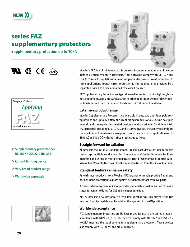
series FAZ supplementary protectorsSupplementary protection up to 10kA
See page 43 about…
Applying
in North America
FAZ
> Supplementary protector per UL 1077 / CSA 22.2 No. 235
> Current limiting device
> Very broad product range
> Worldwide approvals
Moeller’s FAZ line of miniature circuit breakers includes a broad range of devices defined as “supplementary protectors.” These breakers comply with UL 1077 and CSA 22.2 No. 235 regulations defining supplementary over-current protection. In these applications, branch circuit protection is not required, or is provided by a separate device like a fuse or molded case circuit breaker.
FAZ Supplementary Protectors are typically used for control circuits, lighting, busi-ness equipment, appliances and a range of other applications where “closer” pro-tection is desired than that offered by a branch circuit protection device.
Extensive product rangeMoeller Supplementary Protectors are available in one, two and three pole con-figurations and up to 17 different current ratings from 0.5A to 63A. One pole plus neutral, and three-pole plus neutral devices are also available. Six different trip characteristics including B, C, D, K, S and Z curves give you the ability to configure the exact protection scheme you require. Devices can be used in applications up to 480V AC and 48V DC with short circuit ratings up to 10kA.
Straightforward installationAll breakers mount on a standard 35mm DIN-rail. Each device has box terminals that accept multiple conductors. Bus Connectors and Feeder Terminals facilitate mounting and wiring of multiple miniature circuit breaker arrays in control panel assemblies. Power to the circuit breakers can also be fed from the line or load side.
Standard features enhance safetyAs with most products from Moeller, FAZ breaker terminals provide finger and back-of-hand protection to guard against accidental contact with live parts.
A color-coded red/green indicator provides immediate visual indication of device status (green for OFF, red for ON) and isolation function.
All FAZ breakers also incorporate a “trip-free” mechanism. This prevents the trip function from being defeated by holding the operator in the ON position.
Worldwide acceptanceFAZ Supplementary Protectors are UL Recognized for use in the United States in accordance with NFPA 70 (NEC). The devices comply with UL 1077 and CSA 22.2 No.235, meeting the requirements for supplementary protectors. These devices also comply with IEC 60898 and are CE marked.

�1
This graph shows trip-time versus over-current for all FAZ Supplementary Protectors.
Six tripping curves to chooseMoeller FAZ Supplementary Protectors are available with six different tripping characteristics, including Type B, C, D, K, S and Z. Definitions for each trip curve are contained on the ordering pages and can be used to determine the optimal characteristic for your application. For example, low level short-circuit faults in control wiring, such as PLCs, are best protected by devices with Type B trip char-acteristics (3 to 5 X continuous rating of the device (In).
Even though not required by NEC or CEC for Supplemen-tary Protectors, Moeller’s FAZ devices are current limiting, which means they interrupt fault currents within one half cycle. Current limiting devices offer superior protection by reducing peak let-through current and energy.
Discover these advanced features
Captive posidrive terminal screws with finger and back-of-hand protection (IP20)
Available in over 400 configurations including B, C, D, K, S and D trip curves
Short circuit rating to 10kA (@277V AC and 480Y/277V AC for multi-pole to 40A)
Breakers install on standard DIN-rail
Available in one, two and three pole models; one and three pole plus neutral
also available
Trip-free design; breaker cannot be defeated by holding the handle in the ON position
Box terminals accept #16 to #4 wire (1.5 to 25mm2)
Color coded indicator provides breaker status for easy troubleshooting
Complete bus bar system available for quickly installing breaker arrays in panel
assemblies
Breaker information printed on the front of the device for quick identification

�� moellerNA.com FAZ-CAT-NA-1107 Discount Schedule B��
> Designed for resistive or slightly inductive loads.
> Response time of instantaneous trip: 3 – 5 x In current rating
> UL Recognized and CSA Certified as Supplementary Protectors
> For international and domestic use (conform to IEC / EN60898)
Type B CharacteristicsSuitable for applications where protection against low level short circuit faults in control wiring is desired. Instantaneous trip is 3 to 5 x continu-ous rating of device (In). Applications include PLC wiring, business equip-ment, lighting, appliances and some motors. Low magnetic trip point.
Trip Characteristic B – Designed for resistive or slightly inductive loads ➊
Rated Current
In[A]
1 pole 2 poles 3 poles 4 poles
Catalog Number Price Catalog Number Price Catalog Number Price Catalog Number Price6 FAZ-B6/1 20 FAZ-B6/2 58 FAZ-B6/3 85 FAZ-B6/4 115
8 FAZ-B8/1 20 FAZ-B8/2 58 FAZ-B8/3 85 FAZ-B8/4 115
10 FAZ-B10/1 20 FAZ-B10/2 58 FAZ-B10/3 85 FAZ-B10/4 115
12 FAZ-B12/1 20 FAZ-B12/2 58 FAZ-B12/3 85 FAZ-B12/4 115
13 FAZ-B13/1 20 FAZ-B13/2 58 FAZ-B13/3 85 FAZ-B13/4 115
15 FAZ-B15/1 20 FAZ-B15/2 58 FAZ-B15/3 85 FAZ-B15/4 115
16 FAZ-B16/1 20 FAZ-B16/2 58 FAZ-B16/3 85 FAZ-B16/4 115
20 FAZ-B20/1 20 FAZ-B20/2 58 FAZ-B20/3 85 FAZ-B20/4 115
25 FAZ-B25/1 20 FAZ-B25/2 58 FAZ-B25/3 85 FAZ-B25/4 115
32 FAZ-B32/1 20 FAZ-B32/2 58 FAZ-B32/3 85 FAZ-B32/4 115
40 FAZ-B40/1 24 FAZ-B40/2 75 FAZ-B40/3 100 FAZ-B40/4 200
50 FAZ-B50/1 40 FAZ-B50/2 90 FAZ-B50/3 140 FAZ-B50/4 240
63 FAZ-B63/1 42 FAZ-B63/2 105 FAZ-B63/3 180 FAZ-B63/4 260
➊ In North America, these switches are UL recognized and CSA certified as Supple-mentary Protection devices. Per the intent of NEC (National Electrical Code), article 240, and CEC (Canadian Electrical Code), part 1 C22.1, supplementary breakers cannot be used as a substitute for the branch circuit protective device. They can be used to provide over-current protection within an appliance or other electrical equipment where branch circuit over-current protection is already provided, or is not required. See FAZ Branch Circuit Breakers in this catalog.
See Trip Curve chart on opposite page
FAZ Supplementary Protectors
TripCharacteristicB

FAZ-CAT-NA-1107 moellerNA.com �� Discount Schedule B��
> Designed for resistive or slightly inductive loads.
> Response time of instantaneous trip: 3 – 5 x In current rating
> UL Recognized and CSA Certified as Supplementary Protectors
> For international and domestic use (conform to IEC / EN60898)
Type B CharacteristicsSuitable for applications where protection against low level short circuit faults in control wiring is desired. Instantaneous trip is 3 to 5 x continu-ous rating of device (In). Applications include PLC wiring, business equip-ment, lighting, appliances and some motors. Low magnetic trip point.
Trip Characteristic B – Designed for resistive or slightly inductive loads ➊
Rated Current
In[A]
1 pole + Neutral 3 poles + Neutral
Catalog Number Price Catalog Number Price6 FAZ-B6/1N 38 FAZ-B6/3N 105
8 FAZ-B8/1N 38 FAZ-B8/3N 105
10 FAZ-B10/1N 38 FAZ-B10/3N 105
12 FAZ-B12/1N 38 FAZ-B12/3N 105
13 FAZ-B13/1N 38 FAZ-B13/3N 105
15 FAZ-B15/1N 38 FAZ-B15/3N 105
16 FAZ-B16/1N 38 FAZ-B16/3N 105
20 FAZ-B20/1N 38 FAZ-B20/3N 105
25 FAZ-B25/1N 38 FAZ-B25/3N 105
32 FAZ-B32/1N 38 FAZ-B32/3N 105
40 FAZ-B40/1N 45 FAZ-B40/3N 125
50 FAZ-B50/1N 74 FAZ-B50/3N 170
63 FAZ-B63/1N 76 FAZ-B63/3N 205
0.00051 2 3 4 5 6 7 8 9 10 15 20 30 40 50
0.0010.002
0.0050.010.02
0.050.10.2
0.5
10
t [s]
30
60120
300600
1200
36007200
1.13
1.45
B C D
12
5
�
�
� ��
�� �
Speci�ed non-tripping currentInt = 1.13 X In for t > 1 hSpeci�ed tripping currentIt = 1.45 X In for t < 1 h� 2.55 X In : t = 1 – 60 s (In < 32 A) t = 1 – 120 s (In > 32 A)� Type B: 3 X In : t > 0.1 s� Type B: 5 X In : t < 0.1 s� Type C: 5 X In : t > 0.1 s� Type C: 10 X In : t < 0.1 s� Type D: 10 X In : t > 0.1 s� Type D: 20 X In : t < 0.1 s
Multiples of In
➊ In North America, these switches are UL recognized and CSA certified as Supple-mentary Protection devices. Per the intent of NEC (National Electrical Code), article 240, and CEC (Canadian Electrical Code), part 1 C22.1, supplementary breakers cannot be used as a substitute for the branch circuit protective device. They can be used to provide over-current protection within an appliance or other electrical equipment where branch circuit over-current protection is already provided, or is not required. See FAZ Branch Circuit Breakers in this catalog.
FAZ Supplementary Protectors
TripCharacteristicD
�� moellerNA.com FAZ-CAT-NA-1107 Discount Schedule B��
> Designed for inductive loads.
> Response time of instantaneous trip: 5 –10 x In current rating
> UL Recognized and CSA Certified as Supplementary Protectors
> For international and domestic use (conform to IEC / EN60898)
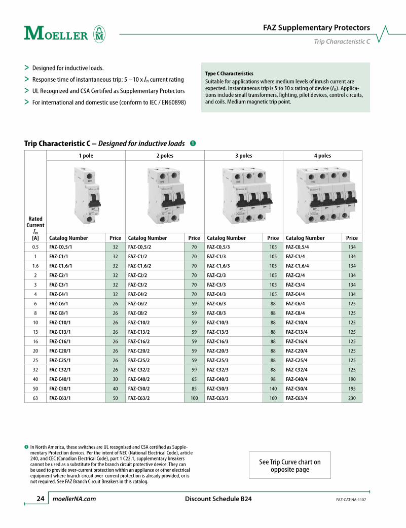
Type C CharacteristicsSuitable for applications where medium levels of inrush current are expected. Instantaneous trip is 5 to 10 x rating of device (In). Applica-tions include small transformers, lighting, pilot devices, control circuits, and coils. Medium magnetic trip point.
Trip Characteristic C – Designed for inductive loads ➊
Rated Current
In[A]
1 pole 2 poles 3 poles 4 poles
Catalog Number Price Catalog Number Price Catalog Number Price Catalog Number Price0.5 FAZ-C0,5/1 32 FAZ-C0,5/2 70 FAZ-C0,5/3 105 FAZ-C0,5/4 134
1 FAZ-C1/1 32 FAZ-C1/2 70 FAZ-C1/3 105 FAZ-C1/4 134
1.6 FAZ-C1,6/1 32 FAZ-C1,6/2 70 FAZ-C1,6/3 105 FAZ-C1,6/4 134
2 FAZ-C2/1 32 FAZ-C2/2 70 FAZ-C2/3 105 FAZ-C2/4 134
3 FAZ-C3/1 32 FAZ-C3/2 70 FAZ-C3/3 105 FAZ-C3/4 134
4 FAZ-C4/1 32 FAZ-C4/2 70 FAZ-C4/3 105 FAZ-C4/4 134
6 FAZ-C6/1 26 FAZ-C6/2 59 FAZ-C6/3 88 FAZ-C6/4 125
8 FAZ-C8/1 26 FAZ-C8/2 59 FAZ-C8/3 88 FAZ-C8/4 125
10 FAZ-C10/1 26 FAZ-C10/2 59 FAZ-C10/3 88 FAZ-C10/4 125
13 FAZ-C13/1 26 FAZ-C13/2 59 FAZ-C13/3 88 FAZ-C13/4 125
16 FAZ-C16/1 26 FAZ-C16/2 59 FAZ-C16/3 88 FAZ-C16/4 125
20 FAZ-C20/1 26 FAZ-C20/2 59 FAZ-C20/3 88 FAZ-C20/4 125
25 FAZ-C25/1 26 FAZ-C25/2 59 FAZ-C25/3 88 FAZ-C25/4 125
32 FAZ-C32/1 26 FAZ-C32/2 59 FAZ-C32/3 88 FAZ-C32/4 125
40 FAZ-C40/1 30 FAZ-C40/2 65 FAZ-C40/3 98 FAZ-C40/4 190
50 FAZ-C50/1 40 FAZ-C50/2 85 FAZ-C50/3 140 FAZ-C50/4 195
63 FAZ-C63/1 50 FAZ-C63/2 100 FAZ-C63/3 160 FAZ-C63/4 230
➊ In North America, these switches are UL recognized and CSA certified as Supple-mentary Protection devices. Per the intent of NEC (National Electrical Code), article 240, and CEC (Canadian Electrical Code), part 1 C22.1, supplementary breakers cannot be used as a substitute for the branch circuit protective device. They can be used to provide over-current protection within an appliance or other electrical equipment where branch circuit over-current protection is already provided, or is not required. See FAZ Branch Circuit Breakers in this catalog.
See Trip Curve chart on opposite page
FAZ Supplementary Protectors
TripCharacteristicC

FAZ-CAT-NA-1107 moellerNA.com �� Discount Schedule B��
> Designed for inductive loads.
> Response time of instantaneous trip: 5 –10 x In current rating
> UL Recognized and CSA Certified as Supplementary Protectors
> For international and domestic use (conform to IEC / EN60898)
Type C CharacteristicsSuitable for applications where medium levels of inrush current are expected. Instantaneous trip is 5 to 10 x rating of device (In). Applica-tions include small transformers, lighting, pilot devices, control circuits, and coils. Medium magnetic trip point.
Trip Characteristic C – Designed for inductive loads ➊
Rated Current
In[A]
1 pole + Neutral 3 poles + Neutral
Catalog Number Price Catalog Number Price0.5 FAZ-C0,5/1N 56 FAZ-C0,5/3N 121
1 FAZ-C1/1N 56 FAZ-C1/3N 121
1.6 FAZ-C1,6/1N 56 FAZ-C1,6/3N 121
2 FAZ-C2/1N 56 FAZ-C2/3N 121
3 FAZ-C3/1N 56 FAZ-C3/3N 121
4 FAZ-C4/1N 56 FAZ-C4/3N 121
6 FAZ-C6/1N 40 FAZ-C6/3N 115
8 FAZ-C8/1N 40 FAZ-C8/3N 115
10 FAZ-C10/1N 40 FAZ-C10/3N 115
13 FAZ-C13/1N 40 FAZ-C13/3N 115
16 FAZ-C16/1N 40 FAZ-C16/3N 115
20 FAZ-C20/1N 40 FAZ-C20/3N 115
25 FAZ-C25/1N 40 FAZ-C25/3N 115
32 FAZ-C32/1N 40 FAZ-C32/3N 115
40 FAZ-C40/1N 45 FAZ-C40/3N 125
50 FAZ-C50/1N 75 FAZ-C50/3N 170
63 FAZ-C63/1N 80 FAZ-C63/3N 195
0.00051 2 3 4 5 6 7 8 9 10 15 20 30 40 50
0.0010.002
0.0050.010.02
0.050.10.2
0.5
10
t [s]
30
60120
300600
1200
36007200
1.13
1.45
B C D
12
5
�
�
� ��
�� �
Speci�ed non-tripping currentInt = 1.13 X In for t > 1 hSpeci�ed tripping currentIt = 1.45 X In for t < 1 h� 2.55 X In : t = 1 – 60 s (In < 32 A) t = 1 – 120 s (In > 32 A)� Type B: 3 X In : t > 0.1 s� Type B: 5 X In : t < 0.1 s� Type C: 5 X In : t > 0.1 s� Type C: 10 X In : t < 0.1 s� Type D: 10 X In : t > 0.1 s� Type D: 20 X In : t < 0.1 s
Multiples of In
➊ In North America, these switches are UL recognized and CSA certified as Supple-mentary Protection devices. Per the intent of NEC (National Electrical Code), article 240, and CEC (Canadian Electrical Code), part 1 C22.1, supplementary breakers cannot be used as a substitute for the branch circuit protective device. They can be used to provide over-current protection within an appliance or other electrical equipment where branch circuit over-current protection is already provided, or is not required. See FAZ Branch Circuit Breakers in this catalog.
FAZ Supplementary Protectors
TripCharacteristicC

�� moellerNA.com FAZ-CAT-NA-1107 Discount Schedule B��
> Designed for highly inductive loads.
> Response time of instantaneous trip: 10 –20 x In current rating
> UL Recognized and CSA Certified as Supplementary Protectors
> For international and domestic use (conform to IEC / EN60898)
Type D CharacteristicsSuitable for applications where high levels of inrush current are expected. Instantaneous trip is 10 to 20 x rating of device (In). The high magnetic trip point prevents nuisance tripping in high inductive ap-plications such as motors, transformers, and power supplies.
Trip Characteristic D – Designed for highly inductive loads ➊
Rated Current
In[A]
1 pole 2 poles 3 poles 4 poles
Catalog Number Price Catalog Number Price Catalog Number Price Catalog Number Price6 FAZ-D6/1 28 FAZ-D6/2 63 FAZ-D6/3 102 FAZ-D6/4 140
8 FAZ-D8/1 28 FAZ-D8/2 63 FAZ-D8/3 102 FAZ-D8/4 140
10 FAZ-D10/1 28 FAZ-D10/2 63 FAZ-D10/3 102 FAZ-D10/4 140
13 FAZ-D13/1 28 FAZ-D13/2 63 FAZ-D13/3 102 FAZ-D13/4 140
16 FAZ-D16/1 28 FAZ-D16/2 63 FAZ-D16/3 102 FAZ-D16/4 140
20 FAZ-D20/1 28 FAZ-D20/2 63 FAZ-D20/3 102 FAZ-D20/4 140
25 FAZ-D25/1 28 FAZ-D25/2 63 FAZ-D25/3 102 FAZ-D25/4 140
32 FAZ-D32/1 28 FAZ-D32/2 63 FAZ-D32/3 102 FAZ-D32/4 140
40 FAZ-D40/1 28 FAZ-D40/2 63 FAZ-D40/3 102 FAZ-D40/4 140
➊ In North America, these switches are UL recognized and CSA certified as Supple-mentary Protection devices. Per the intent of NEC (National Electrical Code), article 240, and CEC (Canadian Electrical Code), part 1 C22.1, supplementary breakers cannot be used as a substitute for the branch circuit protective device. They can be used to provide over-current protection within an appliance or other electrical equipment where branch circuit over-current protection is already provided, or is not required. See FAZ Branch Circuit Breakers in this catalog.
See Trip Curve chart on opposite page
FAZ Supplementary Protectors
TripCharacteristicD
FAZ-CAT-NA-1107 moellerNA.com �� Discount Schedule B��
> Designed for highly inductive loads.
> Response time of instantaneous trip: 10 –20 x In current rating
> UL Recognized and CSA Certified as Supplementary Protectors
> For international and domestic use (conform to IEC / EN60898)
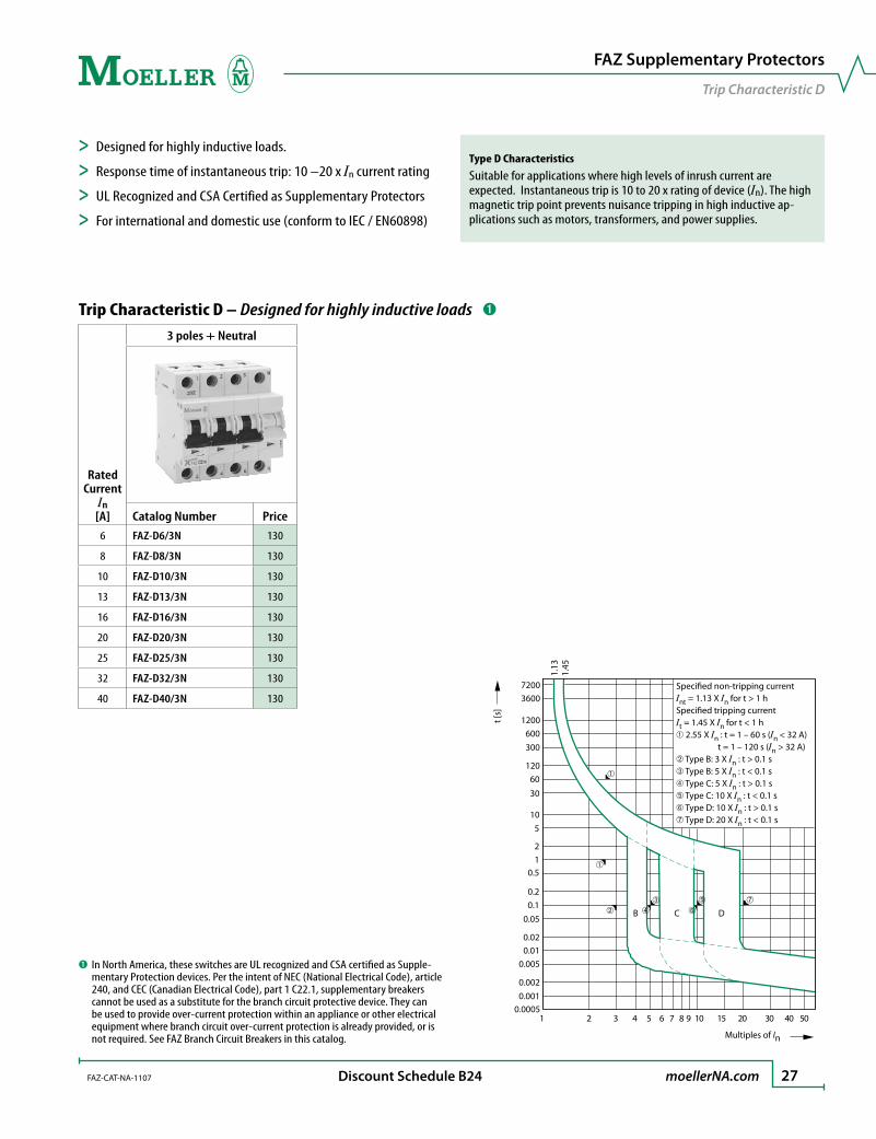
Type D CharacteristicsSuitable for applications where high levels of inrush current are expected. Instantaneous trip is 10 to 20 x rating of device (In). The high magnetic trip point prevents nuisance tripping in high inductive ap-plications such as motors, transformers, and power supplies.
Trip Characteristic D – Designed for highly inductive loads ➊
Rated Current
In[A]
3 poles + Neutral
Catalog Number Price6 FAZ-D6/3N 130
8 FAZ-D8/3N 130
10 FAZ-D10/3N 130
13 FAZ-D13/3N 130
16 FAZ-D16/3N 130
20 FAZ-D20/3N 130
25 FAZ-D25/3N 130
32 FAZ-D32/3N 130
40 FAZ-D40/3N 130
0.00051 2 3 4 5 6 7 8 9 10 15 20 30 40 50
0.0010.002
0.0050.010.02
0.050.10.2
0.5
10
t [s]
30
60120
300600
1200
36007200
1.13
1.45
B C D
12
5
�
�
� ��
�� �
Speci�ed non-tripping currentInt = 1.13 X In for t > 1 hSpeci�ed tripping currentIt = 1.45 X In for t < 1 h� 2.55 X In : t = 1 – 60 s (In < 32 A) t = 1 – 120 s (In > 32 A)� Type B: 3 X In : t > 0.1 s� Type B: 5 X In : t < 0.1 s� Type C: 5 X In : t > 0.1 s� Type C: 10 X In : t < 0.1 s� Type D: 10 X In : t > 0.1 s� Type D: 20 X In : t < 0.1 s
Multiples of In
➊ In North America, these switches are UL recognized and CSA certified as Supple-mentary Protection devices. Per the intent of NEC (National Electrical Code), article 240, and CEC (Canadian Electrical Code), part 1 C22.1, supplementary breakers cannot be used as a substitute for the branch circuit protective device. They can be used to provide over-current protection within an appliance or other electrical equipment where branch circuit over-current protection is already provided, or is not required. See FAZ Branch Circuit Breakers in this catalog.
FAZ Supplementary Protectors
TripCharacteristicD

�� moellerNA.com FAZ-CAT-NA-1107 Discount Schedule B��
> Designed for motors, transformers and upstream electronics.
> Response time of instantaneous trip: 8 –12 x In current rating
> UL Recognized and CSA Certified as Supplementary Protectors
> For international and domestic use (conform to IEC / EN60898)
Type K CharacteristicsSuitable for applications where high levels of inrush current are ex-pected. Instantaneous trip is 8 to 12 x continuous rating of device (In). The high magnetic trip point is ideal for motors and transformers. The narrow range (compared with the type D curve) makes it ideal for ap-plications where nuisance tripping is not an issue.
Trip Characteristic K – Designed for motors, transformers and upstream electronics ➊
Rated Current
In[A]
1 pole 2 poles 3 poles 4 poles
Catalog Number Price Catalog Number Price Catalog Number Price Catalog Number Price0.5 FAZ-K0,5/1 40 FAZ-K0,5/2 87 FAZ-K0,5/3 132 FAZ-K0,5/4 167
1 FAZ-K1/1 40 FAZ-K1/2 87 FAZ-K1/3 132 FAZ-K1/4 167
1.6 FAZ-K1,6/1 40 FAZ-K1,6/2 87 FAZ-K1,6/3 132 FAZ-K1,6/4 167
2 FAZ-K2/1 40 FAZ-K2/2 87 FAZ-K2/3 132 FAZ-K2/4 167
3 FAZ-K3/1 40 FAZ-K3/2 87 FAZ-K3/3 132 FAZ-K3/4 167
4 FAZ-K4/1 40 FAZ-K4/2 87 FAZ-K4/3 132 FAZ-K4/4 167
6 FAZ-K6/1 26 FAZ-K6/2 70 FAZ-K6/3 110 FAZ-K6/4 140
8 FAZ-K8/1 26 FAZ-K8/2 70 FAZ-K8/3 110 FAZ-K8/4 140
10 FAZ-K10/1 26 FAZ-K10/2 70 FAZ-K10/3 110 FAZ-K10/4 140
13 FAZ-K13/1 26 FAZ-K13/2 70 FAZ-K13/3 110 FAZ-K13/4 140
16 FAZ-K16/1 26 FAZ-K16/2 70 FAZ-K16/3 110 FAZ-K16/4 140
20 FAZ-K20/1 26 FAZ-K20/2 70 FAZ-K20/3 110 FAZ-K20/4 140
25 FAZ-K25/1 26 FAZ-K25/2 70 FAZ-K25/3 110 FAZ-K25/4 140
32 FAZ-K32/1 26 FAZ-K32/2 70 FAZ-K32/3 110 FAZ-K32/4 140
40 FAZ-K40/1 34 FAZ-K40/2 80 FAZ-K40/3 155 FAZ-K40/4 155
50 FAZ-K50/1 50 FAZ-K50/2 100 FAZ-K50/3 175 FAZ-K50/4 230
63 FAZ-K63/1 60 FAZ-K63/2 120 FAZ-K63/3 205 FAZ-K63/4 250
Special OrderThese breakers are available by special order only. Contact your Moeller representative for more information.
➊ In North America, these switches are UL recognized and CSA certified as Supple-mentary Protection devices. Per the intent of NEC (National Electrical Code), article 240, and CEC (Canadian Electrical Code), part 1 C22.1, supplementary breakers cannot be used as a substitute for the branch circuit protective device. They can be used to provide over-current protection within an appliance or other electrical equipment where branch circuit over-current protection is already provided, or is not required. See FAZ Branch Circuit Breakers in this catalog.
See Trip Curve chart on opposite page
FAZ Supplementary Protectors
TripCharacteristicK

FAZ-CAT-NA-1107 moellerNA.com �� Discount Schedule B��
> Designed for motors, transformers and upstream electronics.
> Response time of instantaneous trip: 8 –12 x In current rating
> UL Recognized and CSA Certified as Supplementary Protectors
> For international and domestic use (conform to IEC / EN60898)
Type K CharacteristicsSuitable for applications where high levels of inrush current are ex-pected. Instantaneous trip is 8 to 12 x continuous rating of device (In). The high magnetic trip point is ideal for motors and transformers. The narrow range (compared with the type D curve) makes it ideal for ap-plications where nuisance tripping is not an issue.
Trip Characteristic K – Designed for motors, transformers and upstream electronics ➊
Rated Current
In[A]
3 poles + Neutral
Catalog Number Price0.5 FAZ-K0,5/3N 152
1 FAZ-K1/3N 152
1.6 FAZ-K1,6/3N 152
2 FAZ-K2/3N 152
3 FAZ-K3/3N 152
4 FAZ-K4/3N 152
6 FAZ-K6/3N 130
8 FAZ-K8/3N 130
10 FAZ-K10/3N 130
13 FAZ-K13/3N 130
16 FAZ-K16/3N 130
20 FAZ-K20/3N 130
25 FAZ-K25/3N 130
32 FAZ-K32/3N 130
40 FAZ-K40/3N 160
50 FAZ-K50/3N 200
63 FAZ-K63/3N 230
Special OrderThese breakers are available by special order only.
Contact your Moeller representative for more information.
0.00051 2 3 4 5 6 7 8 9 10 15 20 30 40 50
0.0010.002
0.0050.010.02
0.050.10.2
0.512
510
t[s]
30
60120
300600
1200
36007200
1.05
1.30
Speci�ed non-tripping current nt = 1.05 u nfor t > 1 hSpeci�ed tripping current t = 1.30 u nfor t < 1 hI
I
I
I
u rated current
K
➊ In North America, these switches are UL recognized and CSA certified as Supple-mentary Protection devices. Per the intent of NEC (National Electrical Code), article 240, and CEC (Canadian Electrical Code), part 1 C22.1, supplementary breakers cannot be used as a substitute for the branch circuit protective device. They can be used to provide over-current protection within an appliance or other electrical equipment where branch circuit over-current protection is already provided, or is not required. See FAZ Branch Circuit Breakers in this catalog.
FAZ Supplementary Protectors
TripCharacteristicK

�0 moellerNA.com FAZ-CAT-NA-1107 Discount Schedule B��
> Designed for protection of electronic devices.
> Response time of instantaneous trip: 2 –3 x In current rating
> UL Recognized and CSA Certified as Supplementary Protectors
> For international and domestic use (conform to IEC / EN60898)
Type Z CharacteristicsSuitable for applications where semiconductors and other components that fail open are used. Instantaneous trip is 2 to 3 x continuous rating of device (In). The short thermal delay and low magnetic trip point are ideal for applications where devices and components have low surge and short circuit tolerances.
Trip Characteristic Z – Designed for protection of electronic devices ➊
Rated Current
In[A]
1 pole 2 poles 3 poles 4 poles
Catalog Number Price Catalog Number Price Catalog Number Price Catalog Number Price0.5 FAZ-Z0,5/1 40 FAZ-Z0,5/2 87 FAZ-Z0,5/3 132 FAZ-Z0,5/4 1661 FAZ-Z1/1 40 FAZ-Z1/2 87 FAZ-Z1/3 132 FAZ-Z1/4 166
1.6 FAZ-Z1,6/1 40 FAZ-Z1,6/2 87 FAZ-Z1,6/3 132 FAZ-Z1,6/4 1662 FAZ-Z2/1 40 FAZ-Z2/2 87 FAZ-Z2/3 132 FAZ-Z2/4 1663 FAZ-Z3/1 40 FAZ-Z3/2 87 FAZ-Z3/3 132 FAZ-Z3/4 1664 FAZ-Z4/1 40 FAZ-Z4/2 87 FAZ-Z4/3 132 FAZ-Z4/4 1666 FAZ-Z6/1 28 FAZ-Z6/2 70 FAZ-Z6/3 110 FAZ-Z6/4 1408 FAZ-Z8/1 28 FAZ-Z8/2 70 FAZ-Z8/3 110 FAZ-Z8/4 140
10 FAZ-Z10/1 28 FAZ-Z10/2 70 FAZ-Z10/3 110 FAZ-Z10/4 14013 FAZ-Z13/1 28 FAZ-Z13/2 70 FAZ-Z13/3 110 FAZ-Z13/4 14016 FAZ-Z16/1 28 FAZ-Z16/2 70 FAZ-Z16/3 110 FAZ-Z16/4 14020 FAZ-Z20/1 28 FAZ-Z20/2 70 FAZ-Z20/3 110 FAZ-Z20/4 14025 FAZ-Z25/1 28 FAZ-Z25/2 70 FAZ-Z25/3 110 FAZ-Z25/4 14032 FAZ-Z32/1 32 FAZ-Z32/2 70 FAZ-Z32/3 110 FAZ-Z32/4 14040 FAZ-Z40/1 40 FAZ-Z40/2 80 FAZ-Z40/3 135 FAZ-Z40/4 15550 FAZ-Z50/1 60 FAZ-Z50/2 130 FAZ-Z50/3 175 FAZ-Z50/4 24063 FAZ-Z63/1 65 FAZ-Z63/2 150 FAZ-Z63/3 205 FAZ-Z63/4 280
Special Order – These breakers are available by special order only. Contact your Moeller representative for more information.
0.00051 2 3 4 5 6 7 8 9 10 15 20 30 40 50
0.0010.002
0.0050.010.02
0.050.10.2
0.512
10
t[s]
30
60120
300600
1200
36007200
1.05
1.30
Speci�ed non-tripping current nt = 1.05 u nfor t > 1 hSpeci�ed tripping current t = 1.30 u nfor t < 1 hI
I
I
I
u rated current
5
Z
➊ In North America, these switches are UL recognized and CSA certified as Supple-mentary Protection devices. Per the intent of NEC (National Electrical Code), article 240, and CEC (Canadian Electrical Code), part 1 C22.1, supplementary breakers cannot be used as a substitute for the branch circuit protective device. They can be used to provide over-current protection within an appliance or other electrical equipment where branch circuit over-current protection is already provided, or is not required. See FAZ Branch Circuit Breakers in this catalog.
FAZ Supplementary Protectors
TripCharacteristicZ

FAZ-CAT-NA-1107 moellerNA.com �1 Discount Schedule B��
> Designed for control circuits with high inrush
> Response time of instantaneous trip: 13 –17 x In current rating
> UL Recognized and CSA Certified as Supplementary Protectors
> For international and domestic use (conform to IEC / EN60898)
Type S CharacteristicsSuitable for applications with highly inductive loads, especially in control circuits with coils and light filaments. Instantaneous response between 13 to 17 x rating of device (In).
Trip Characteristic S – Designed for control circuits with high inrush ➊
Rated Current
In[A]
1 pole 2 poles
Catalog Number Price Catalog Number Price1 FAZ-S1/1 40 FAZ-S1/2 88
2 FAZ-S2/1 40 FAZ-S2/2 88
3 FAZ-S3/1 40 FAZ-S3/2 88
4 FAZ-S4/1 40 FAZ-S4/2 88
6 FAZ-S6/1 28 FAZ-S6/2 60
10 FAZ-S10/1 28 FAZ-S10/2 60
16 FAZ-S16/1 28 FAZ-S16/2 60
20 FAZ-S20/1 28 FAZ-S20/2 60
25 FAZ-S25/1 28 FAZ-S25/2 75
32 FAZ-S32/1 32 FAZ-S32/2 85
40 FAZ-S40/1 40 FAZ-S40/2 90
Special OrderThese breakers are available by special order only.
Contact your Moeller representative for more information.
0.00051 2 3 4 5 6 7 8 9 10 15 20 30 40 50
0.0010.002
0.0050.010.02
0.050.10.2
0.512
510
t[s]
30
60120
300600
1200
36007200
1.05
1.30
Speci�ed non-tripping current nt = 1.05 u nfor t > 1 hSpeci�ed tripping current t = 1.30 u nfor t < 1 hI
I
I
I
u rated current
S
➊ In North America, these switches are UL recognized and CSA certified as Supple-mentary Protection devices. Per the intent of NEC (National Electrical Code), article 240, and CEC (Canadian Electrical Code), part 1 C22.1, supplementary breakers cannot be used as a substitute for the branch circuit protective device. They can be used to provide over-current protection within an appliance or other electrical equipment where branch circuit over-current protection is already provided, or is not required. See FAZ Branch Circuit Breakers in this catalog.
FAZ Supplementary Protectors
TripCharacteristicS

�� moellerNA.com FAZ-CAT-NA-1107 Discount Schedule B��
Auxiliary Contacts and Voltage Trips
Module Circuit Diagram Description
RatedOperational
Voltage Catalog Number PriceStandard Auxiliary Contacts
1 NO / 1 NCInstalls on left side of FAZ or Shunt TripMax. one per FAZ (1077) deviceSwitches when FAZ is tripped electrically or manually
••••
230V AC
FAZ-XHIN11 30
12 14
11
1 changeover contactInstalls on left side of FAZ or Shunt TripMax. one per FAZ (1077) deviceSwitches when FAZ is tripped electrically or manually
••••
FAZ-XHINW1 31
Auxiliary / Trip Indicating Contact
Two-pole auxiliary mode
Trip indicating mode
Small selector screw changes modeTwo Form C (changeover) contactsInstalls on left side of FAZ or Shunt TripAuxiliary contacts switch when FAZ is tripped electrically or manuallyTrip indicating contact switches only when FAZ is tripped electrically
••••
•
230V AC FAZ-XAM002 50
Undervoltage Trip
D2
U
D1Prevents FAZ from operating unless voltage is present Installs on left side of FAZ Includes test button
•
••
115V AC FAZ-XUA(115VAC) 148
230V AC FAZ-XUA(230VAC) 148
400V AC FAZ-XUA(400VAC) 148
Shunt Trip
C2
C1
Allows remote trip of FAZInstalls on left side of FAZ
••
110–415V AC110–230V DC FAZ-XAA-C-12-110VAC 55
12 – 110V AC12 – 60V DC FAZ-XAA-C-110-415VAC 55
Allowable combinations of accessories
XAMXHI FAZ
CircuitBreaker
or
XAMXHI FAZ
CircuitBreaker
XAA
ShuntTrip
or
FAZ
CircuitBreaker
XUA
UnderVTrip
FAZ Supplementary Protectors
Accessories

FAZ-CAT-NA-1107 moellerNA.com �� Discount Schedule B��
Bus Bar System ➊
Description
Number of Poles per
DeviceNumber of Terminals
RatedOperationalCurrent (A)
➊ Catalog Number PriceWithout auxiliary contacts
For connecting FAZ Supplemen-tary Protectors without auxiliary contacts. May be fed from line or
load side.
FAZFAZ FAZ
1
2
80
EVG-16/1PHAS/2MODUL 7
6 EVG-16/1PHAS/6MODUL 13
12 EVG-16/1PHAS/12MODUL 18
2
4 EVG-16/2PHAS/4MODUL 19
6 EVG-16/2PHAS/6MODUL 25
12 EVG-16/2PHAS/12MODUL 40
3
6 EVG-16/3PHAS/6MODUL 32
9 EVG-16/3PHAS/9MODUL 42
12 EVG-16/3PHAS/12MODUL 55
16 EVG-16/3PHAS/16MODUL 70
20 EVG-16/3PHAS/20MODUL 90
48 EVG-16/4PHAS/8MODUL 56
12 EVG-16/4PHAS/12MODUL 85
With auxiliary contacts
For connecting FAZ Supplemen-tary Protectors with auxiliary
contacts. May be fed from line or load side.
FAZFAZXHI XAM
1
2
80
EVG-16/1PHAS/2MODUL/HI 11
6 EVG-16/1PHAS/6MODUL/HI 25
9 EVG-16/1PHAS/9MODUL/HI 28
2
4 EVG-16/2PHAS/4MODUL/HI 25
6 EVG-16/2PHAS/6MODUL/HI 32
10 EVG-16/2PHAS/10MODUL/HI 40
3
6 EVG-16/3PHAS/6MODUL/HI 35
12 EVG-16/3PHAS/12MODUL/HI 60
➊ IEC rated only.
FAZ Supplementary Protectors
Accessories

�� moellerNA.com FAZ-CAT-NA-1107 Discount Schedule B��
Incoming Supply Terminals ➊
Accessories Description Installation Catalog Number PriceFork Connector
Fork connectorAccommodates conductors up to 25 mm2 (~ AWG 4)Finger-safe connection
•
•
FAZ-XK25
FAZ-XK25
FAZ FAZ
FAZ-XK25 16
Protective Accessories
Accessories Description Catalog Number PriceBus Bar Terminal Cover
For covering unused terminals ZV-BS-G 2
Padlock Hasp
Prevents reactivation of the device during maintenance Holds one padlock
•
•IS/SPE-1TE 40
➊ IEC rated only.
FAZ Supplementary Protectors
Accessories

FAZ-CAT-NA-1107 moellerNA.com ��
Let-through energy I2t
2 A
1 A
0.5 A
10 A13 A16 A20 A25 A32 A40 A
50 A63 A
4 A
3 A
6 A
0.5 1.5 151 2 3 4 5 6 7 8 9 10
103
104
105
8
6
4
2
1.5
8
6
4
2
8
6
4
3
1.5
2
.2∫i dt[A s] FAZ-B
FAZ-C
FAZ-...-B4HI
cc rms [kA]I
10 A
13 A16 A20 A25 A32 A40 A
6 A
0.5 1.5 151 2 3 4 5 6 7 8 9 10
104
105
8
6
4
2
1.5
8
6
4
2
1.5
8
6
4
103
2
.2∫i dt[A s] FAZ-D
cc rms [kA]I
i2dt[A2s]
103
1.5
0.5 1 1.5 2 3 4 5
2
3
4
6
104
8
1.5
2
3
4
6
8
5
4
3
50 A63 A
FAZ-K
40 A
32 A25 A20 A16 A
13 A
10 A
6 A
8 A
4 A3 A
1.6 A
0.5 A
1 A
2 A
6 7 8 9 10
I cc rms [kA]
103
1.5
0.5 1 1.5 2 3 4 5
2
3
4
6
104
8
1.5
2
3
4
6
8
5
i2dt[A2s]
40 A
FAZ-S
32 A25 A
20 A
16 A
10 A
4 A
6 A
3 A2 A
1 A
6 7 8 9 10
I cc rms [kA]
FAZ Supplementary Protectors
Let-throughCharacteristics

�� moellerNA.com FAZ-CAT-NA-1107
103
1.5
0.5 1 1.5 2 3 4 5
2
3
4
6
104
8
1.5
2
3
4
6
8
5
i2dt[A2s]
40 A50 A63 A
FAZ-Z
32 A
25 A20 A16 A
8 A
10 A
4 A
6 A
3 A
2 A
1.6 A1 A0.5 A
6 7 8 9 10
4
3
I cc rms [kA]
Let-through energy I2t
Let-through current ID
FAZ Supplementary Protectors
Let-throughCharacteristics

FAZ-CAT-NA-1107 moellerNA.com ��
Let-through current ID
FAZ Supplementary Protectors
Let-throughCharacteristics
�� moellerNA.com FAZ-CAT-NA-1107
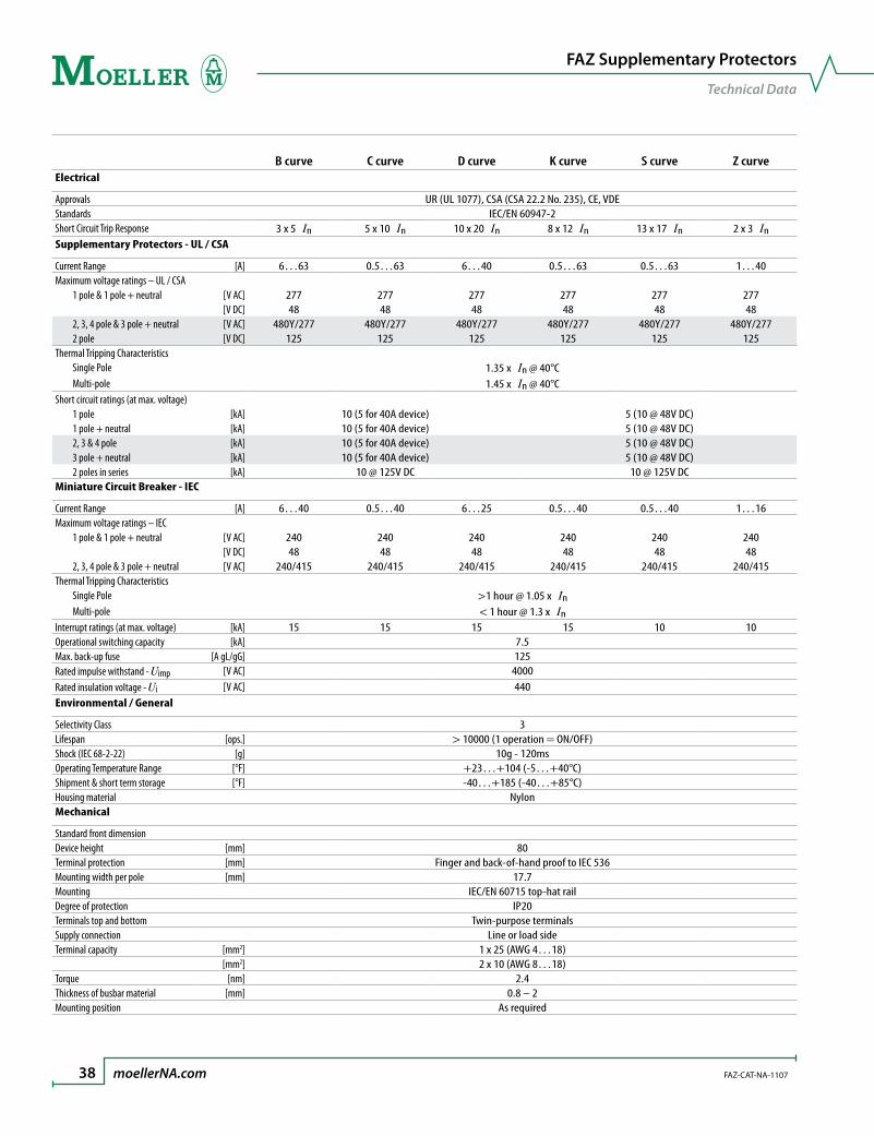
B curve C curve D curve K curve S curve Z curveElectrical
Approvals UR (UL 1077), CSA (CSA 22.2 No. 235), CE, VDEStandards IEC/EN 60947-2Short Circuit Trip Response 3 x 5 In 5 x 10 In 10 x 20 In 8 x 12 In 13 x 17 In 2 x 3 InSupplementary Protectors - UL / CSA
Current Range [A] 6…63 0.5…63 6…40 0.5…63 0.5…63 1…40Maximum voltage ratings – UL / CSA 1 pole & 1 pole + neutral [V AC] 277 277 277 277 277 277
[V DC] 48 48 48 48 48 48 2, 3, 4 pole & 3 pole + neutral [V AC] 480Y/277 480Y/277 480Y/277 480Y/277 480Y/277 480Y/277 2 pole [V DC] 125 125 125 125 125 125Thermal Tripping Characteristics Single Pole 1.35 x In @ 40°C Multi-pole 1.45 x In @ 40°CShort circuit ratings (at max. voltage) 1 pole [kA] 10 (5 for 40A device) 5 (10 @ 48V DC) 1 pole + neutral [kA] 10 (5 for 40A device) 5 (10 @ 48V DC) 2, 3 & 4 pole [kA] 10 (5 for 40A device) 5 (10 @ 48V DC) 3 pole + neutral [kA] 10 (5 for 40A device) 5 (10 @ 48V DC) 2 poles in series [kA] 10 @ 125V DC 10 @ 125V DCMiniature Circuit Breaker - IEC
Current Range [A] 6…40 0.5…40 6…25 0.5…40 0.5…40 1…16Maximum voltage ratings – IEC 1 pole & 1 pole + neutral [V AC] 240 240 240 240 240 240
[V DC] 48 48 48 48 48 48 2, 3, 4 pole & 3 pole + neutral [V AC] 240/415 240/415 240/415 240/415 240/415 240/415Thermal Tripping Characteristics Single Pole >1 hour @ 1.05 x In Multi-pole < 1 hour @ 1.3 x InInterrupt ratings (at max. voltage) [kA] 15 15 15 15 10 10Operational switching capacity [kA] 7.5Max. back-up fuse [A gL/gG] 125Rated impulse withstand - Uimp [V AC] 4000Rated insulation voltage - Ui [V AC] 440Environmental / General
Selectivity Class 3Lifespan [ops.] > 10000 (1 operation = ON/OFF)Shock (IEC 68-2-22) [g] 10g - 120msOperating Temperature Range [°F] +23…+104 (-5…+40°C)Shipment & short term storage [°F] -40…+185 (-40…+85°C)Housing material NylonMechanical
Standard front dimensionDevice height [mm] 80Terminal protection [mm] Finger and back-of-hand proof to IEC 536Mounting width per pole [mm] 17.7Mounting IEC/EN 60715 top-hat railDegree of protection IP20Terminals top and bottom Twin-purpose terminalsSupply connection Line or load sideTerminal capacity [mm2] 1 x 25 (AWG 4…18)
[mm2] 2 x 10 (AWG 8…18)Torque [nm] 2.4Thickness of busbar material [mm] 0.8 – 2Mounting position As required
FAZ Supplementary Protectors
TechnicalData
FAZ-CAT-NA-1107 moellerNA.com ��
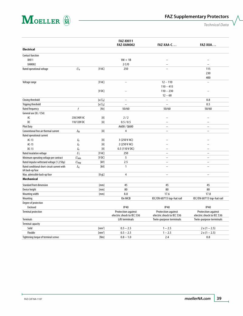
FAZ-XHI11 FAZ-XAM002 FAZ-XAA-C… FAZ-XUA…
Electrical
Contact function XHI11 1M + 1B – – XAM002 2 C/O – –Rated operational voltage Un [V AC] 250 – 115
230400
Voltage range [V AC] – 12 – 110 –110 – 415
[V DC] – 110 – 230 –12 – 60
Closing threshold [x Un] – – 0.8Tripping threshold [x Un] – – 0.5Rated frequency ƒ [Hz] 50/60 50/60 50/60General use (UL / CSA) AC 230/240V AC [A] 2 / 2 – – DC 110/120V DC [A] 0.5 / 0.5 – –Pilot Duty A600 / Q600 – –Conventional free air thermal current Ith [A] 4 – –Rated operational current AC-13 Ie [A] 3 (250 V AC) – – AC-15 Ie [A] 2 (250 V AC) – – DC-13 Ie [A] 0.5 (110 V DC) – –Rated insulation voltage Ui [V AC] 250 – –Minimum operating voltage per contract Umin [V DC] 5 – –Rated impulse withstand voltage (1.2/50µ) Uimp [kV] 2.5 – –Rated conditional short-circuit current with Isc 6A back-up fuse
[kA] 1 – –
Max. admissible back-up fuse [A gL] 4 – –Mechanical
Standard front dimension [mm] 45 45 45Device height [mm] 80 80 80Mounting width [mm] 8.8 17.6 17.8Mounting On MCB IEC/EN 60715 top-hat rail IEC/EN 60715 top-hat railDegree of protection Enclosed IP40 IP40 IP40Terminal protection Protection against
electric shock to IEC 536Protection against
electric shock to IEC 536Protection against
electric shock to IEC 536Terminals Lift terminals Twin-purpose terminals Twin-purpose terminalsTerminal capacity Solid [mm2] 0.5 – 2.5 1 – 2.5 2 x (1 – 2.5) Flexible [mm2] 0.5 – 2.5 1 – 2.5 2 x (1 – 2.5)Tightening torque of terminal screws [Nm] 0.8 – 1.0 2.4 0.8
FAZ Supplementary Protectors
TechnicalData

�0 moellerNA.com FAZ-CAT-NA-1107
Influence of the ambient temperature on the thermal tripping behaviorCorrected values of the rated current dependent on the ambient temperature
Ambient Temperature T [˚C]
In [A] -25 -20 -10 0 10 20 30 35 40 45 50 55 600.16 0.20 0.19 0.19 0.18 0.17 0.17 0.16 0.16 0.15 0.15 0.15 0.14 0.140.25 0.31 0.30 0.29 0.28 0.27 0.26 0.25 0.25 0.24 0.24 0.23 0.23 0.220.5 0.61 0.60 0.58 0.56 0.54 0.52 0.50 0.49 0.48 0.47 0.46 0.45 0.44
0.75 0.92 0.90 0.87 0.84 0.81 0.78 0.75 0.74 0.73 0.71 0.69 0.68 0.661 1.2 1.2 1.2 1.1 1.1 1.0 1.0 0.99 0.97 0.95 0.93 0.90 0.89
1.5 1.8 1.8 1.7 1.7 1.6 1.6 1.5 1.5 1.5 1.4 1.4 1.4 1.31.6 2.0 1.9 1.9 1.8 1.7 1.7 1.6 1.6 1.5 1.5 1.5 1.4 1.42 2.4 2.4 2.3 2.2 2.2 2.1 2.0 2.0 1.9 1.9 1.9 1.8 1.8
2.5 3.1 3.0 2.9 2.8 2.7 2.6 2.5 2.5 2.4 2.4 2.3 2.3 2.23 3.7 3.6 3.5 3.4 3.3 3.1 3.0 3.0 2.9 2.8 2.8 2.7 2.7
3.5 4.3 4.2 4.1 3.9 3.8 3.7 3.5 3.4 3.4 3.3 3.2 3.2 3.14 4.9 4.8 4.7 4.5 4.3 4.2 4.0 3.9 3.9 3.8 3.7 3.6 3.55 6.1 6.0 5.8 5.6 5.4 5.2 5.0 4.9 4.8 4.7 4.6 4.5 4.46 7.3 7.2 7.0 6.7 6.5 6.3 6.0 5.9 5.8 5.7 5.6 5.4 5.38 9.8 9.6 9.3 9.0 8.7 8.4 8.0 7.9 7.7 7.6 7.4 7.2 7.1
10 12 12 12 11 11 10 10 9.9 9.7 9.5 9.3 9.0 8.912 15 14 14 13 13 13 12 12 12 11 11 11 1113 16 16 15 15 14 14 13 13 13 12 12 12 1215 18 18 17 17 16 16 15 15 15 14 14 14 1316 20 19 19 18 17 17 16 16 15 15 15 14 1420 24 24 23 22 22 21 20 20 19 19 19 18 1825 31 30 29 28 27 26 25 25 24 24 23 23 2232 39 38 37 36 35 33 32 32 31 30 30 29 2840 49 48 47 45 43 42 40 39 39 38 37 36 3550 61 60 58 56 54 52 50 49 48 47 46 45 4463 77 76 73 71 68 66 63 62 61 60 58 57 56
Influence of the mains frequencyInfluence of the mains frequency on the tripping behavior IMA of the instantaneous release
Mains frequency f [Hz]
16 2∕3 50 60 100 200 300 400IMA(f)IMA (50 Hz) [%] 91 100 101 106 115 134 141
Load carrying capacity of adjoining miniature circuit-breakers
FAZ Supplementary Protectors
TechnicalData

FAZ-CAT-NA-1107 moellerNA.com �1
Miniature circuit-breakersFAZ
70.8
45
9.4
60
445.553.135.417.7
80
4580
44
60
5.58.8
4580
44
60
5.58.8
Auxiliary ContactsFAZ-XHI11 FAZ-XAM002
17.6
80
26.2
30.5 105.5
44
60
45
17.8
80
445.5
60
45
Shunt ReleasesFAZ-XAA
Undervoltage ReleasesFAZ-XUA
Dimensions are in millimeters.Not intended for manufacturing purposes.
FAZ Supplementary Protectors
Dimensions

�� moellerNA.com FAZ-CAT-NA-1107
BusbarEVG-16
a b b1 cEVG-16/1PHAS/2MODUL 33 25.9 14 3.4
EVG-16/1PHAS/6MODUL 105 25.9 14 3.4
EVG-16/1PHAS/12MODUL 210 25.9 14 3.4
EVG-16/2PHAS/4MODUL 75.5 30.9 19 7.3
EVG-16/2PHAS/6MODUL 105 30.9 19 7.3
EVG-16/2PHAS/12MODUL 209.5 30.9 19 7.3
EVG-16/3PHAS/6MODUL 102.5 30.9 19 10.3
EVG-16/3PHAS/9MODUL 156 30.9 19 10.3
EVG-16/3PHAS/12MODUL 209.5 30.9 19 10.3
EVG-16/3PHAS/16MODUL 285 30.9 19 10.3
EVG-16/3PHAS/20MODUL 353 30.9 19 10.3
EVG-16/4PHAS/8MODUL 138 30.9 19 13.3EVG-16/4PHAS/12MODUL 209.5 30.9 19 13.3
c
b1
ba
1.5
a b b1 cEVG-16/1PHAS/2MODUL/HI 60 25.9 14 3.4
EVG-16/1PHAS/6MODUL/HI 156.5 25.9 14 3.4
EVG-16/1PHAS/9MODUL/HI 237 25.9 14 3.4
EVG-16/2PHAS/4MODUL/HI 75.5 30.9 19 7.3
EVG-16/2PHAS/6MODUL/HI 120 30.9 19 7.3
EVG-16/2PHAS/10MODUL/HI 209.5 30.9 19 7.3
EVG-16/3PHAS/6MODUL/HI 115 30.9 19 10.3
EVG-16/3PHAS/12MODUL/HI 237 30.9 19 10.3
Dimensions are in millimeters.Not intended for manufacturing purposes.
FAZ Supplementary Protectors
Dimensions

Applying branch circuit breakers and supplementary protectors in North America
AndreR.FortinManager,Codes&Standards
MoellerElectricInc.

��
Applying branch circuit breakers and supplementary protectors in North America
FAZ-NA(RT) FAZ
IntroductionMoeller offers two types of miniature circuit breakers for use in North America. The first version, FAZ-NA(RT), fully complies with the Molded Case Circuit Breaker standard UL 489 and the Canadian equiv-alent CSA 22.2 No. 5-02, which states that devices within that range can be applied legitimately as Feeder and Branch Circuit Protective devices per the US and Canadian electrical Codes.
A second version, FAZ, is recognized per UL 1077 and certified per CSA C22.2 No. 235 as a Supplemen-tary Protector and can be fully utilized per the NEC and CEC Codes in that capacity. For international purposes, the entire FAZ family is CE marked and in full conformity with the applicable IEC standards for miniature circuit breakers, EN/IEC 60 898 and EN/IEC 60 947-2.
Both FAZ and FAZ-NA(RT) are offered in various ampere ranges and tripping characteristics. This paper will focus on the main technical aspects of the entire line and should assist in the proper selection and application of all versions.
Characteristics of IEC-style Miniature Circuit BreakersBecause Moeller’s FAZ Miniature Circuit Breakers are IEC-style devices, it is important to understand their inherent characteristics before examining them in the context of UL / CSA requirements.
IEC-style miniature circuit breakers are thermal-magnetic, inverse time protective devices, with both a fixed thermal and a fixed magnetic trip setting.
They are toggle operated, and like all modern circuit breakers, feature a “trip-free” mechanism. This means that the tripping action works independently of the handle position for safety purposes.
They all mount on a standard 35mm DIN-rail and share a common single pole width of 17.5 mm.
Most comply with EN/IEC 60898 and EN/IEC 60947-2, which are the relevant international performance and testing standards for low voltage (<1000V) circuit breakers in Europe and the rest of the IEC world.
Outside North America, they can be used in both residential and industrial applications as feeder and branch circuit protective devices.
In North America, most European Miniature Circuit Breakers are only UL recognized and CSA cer-tified as “Supplementary Protectors,” meaning they cannot be utilized as feeder or branch circuit protective devices per the local electrical codes. This commonly restricts their use to applications where “closer” protection is desired than that offered by a branch circuit protection device.
Some variations, like Moeller’s new FAZ-NA(RT) line have been specially designed to meet UL and CSA requirements for Molded Case Circuit Breakers and are marked accordingly. This makes them suitable for feeder and branch circuit protection applications in North America.
•
•
•
•
•
•
•

��
Supplementary ProtectorsAs mentioned, the standard Moeller FAZ line fulfills all of the criteria per Code of “Supplementary Overcurrent Protective Devices,” or “Supplementary Protectors,” as they are better known.
What is the definition of a Supplementary Protector per North American standards?
A Supplementary Protector is a manual reset device designed to open the circuit automatically on a pre-determined value of time versus current or voltage within an appliance or other electrical equipment. It may also be provided with manual means for opening or closing the circuit. (Source: UL 1077)
In the US (and similarly in Canada) the NEC 2005 further defines supplementary protectors as devices intended to provide limited overcurrent protection for specific applications, such as lighting fixtures and appliances. This limited protection is in addition to the protection provided in the required branch circuit by the branch circuit overcurrent protective device.
Clearly, the underlying message in those definitions is that Supplementary Protectors are not Branch Circuit overcurrent protective devices per Code, and neither are they tested that way per UL and CSA standards. They cannot replace the primary protective role performed by listed and certified molded case circuit breakers and fuses.
That explains, in part, their status by UL as “recognized only” devices. Supplementary Protectors will never bear a UL listing mark, simply because their suitability as protective devices is dependent on a number of acceptability conditions which can vary from make to make and ultimately define the manner in which they can be properly applied per Code. The manufacturer should be consulted in all cases when evaluating the suitability of “recognized only” components such as UL 1077 Supplemen-tary Protectors.
Moeller FAZ protectors are not subject to any specific restrictions in this respect, other than, like all Supplementary Protectors, they must never be used as a substitute for true listed and certified pri-mary overcurrent protective devices.
Where can Supplementary Protectors be used effectively per Code standards?
Moeller’s FAZ Supplementary Protectors can be used in a number of significant areas. To more clearly illustrate potential applications, however, let’s first present the NEC’s definition of a Branch Circuit:
The circuit conductors between the final overcurrent device protecting the circuit and the outlets. (Source: NEC 2005).
A branch circuit is that portion of the electrical distribution system which extends beyond the final branch circuit overcurrent protective device and is intended to serve lighting, appliance, motors and/or other individual loads.
Typically, the Branch Circuit Overcurrent Protective Device (BOPD) will be either a listed molded case circuit breaker or fuse. Supplementary Protectors, such as Moeller’s line of FAZ devices, can therefore be added to any of these branch circuits to “supplement” the branch circuit protection. Examples of applications ideally suited for these devices can include:
Any type of OEM electrical equipment which is fed from a service panel board and which often requires additional protection for sensitive internal circuitry and components. (Test and medical equipment, copiers and printers, computers and power supplies etc.)
The need for manual reset devices with optional accessories such as auxiliary contacts and volt-age trips to accomplish fuseless protective circuit designs and enhance operational diagnostics.
Isolation and protection of control cable, coils, contacts and circuit elements of motor control circuits tapped from the load side of the branch circuit protective device. (per NEC 430.72).
Protection of control circuit transformers, especially in the secondary where the manual reset protector can be used to isolate, as well as protect, secondary circuit conductors and loads.
•
•
•
•
“Recognized only” mark from UL
All UL 1077 Supplementary Protectors are recognized only devices. They are subject to Conditions of Acceptability in order to be applied properly per the intent of the Electrical Codes.

��
Typical let-through curve profile of a current-limiting device
- The X axis shows the prospective short circuit current levels.- The Y axis indicates the actual let-through values (Let-through current in the
example shown) at those prospective fault ratings for each FAZ device plotted.As can be interpreted from the bend in the plotted curves, each device acts to limit the damaging let-through energy (and current) at those values of short circuit current.In a conventional circuit breaker, no similar current limiting effect can be denoted and a device takes at least a few cycles to ultimately clear the fault. By design, all Moeller FAZ Supplementary Protectors and Miniature Molded Case circuit breakers are current limiting protective devices.
Primary protection, although permissible, is not an ideal application since these protectors, like fuses, have a fixed current setting not ideally matched to the transformer’s primary rated current. A better choice for primary protection of control transformers consists of manual motor controllers additionally evaluated and marked as “Tap Conductor Protectors,” such as Moeller’s PKZM0 device, since these have an adjustable thermal dial which can be set to the exact primary current rating of the transformer. Consult Moeller for additional information on this application.
IEC based miniature circuit breakers, such as Moeller’s entire FAZ line, are much more than just conven-tional supplementary protectors from an internal design point of view and can provide an ideal means to enhance the protective capabilities of any circuit.
As mentioned , they are in full compliance with the pertinent EN/IEC standards (EN/IEC 60898, EN/IEC 60947-2) for miniature circuit breakers and can thus be applied, outside of North America, as full-fledged stand-alone overcurrent protective devices in both residential and industrial applications.
As this typical let-through current curve shows, they are highly current limiting devices which appreciably limit the amount of let-through current and destructive energy within their ratings to minimize damage levels to downstream loads and circuits.
Circuit breakers that are classified as “current limiting” have the ability to clear dam-aging short circuit currents within the first half cycle of the fault, resulting in better overall protection for all circuit components.
They come in a variety of tripping characteristics, which is ideal when custom-izing protection to match specific load requirements. Moeller FAZ Supplementary Protectors offer a total of six different protection characteristics for this purpose: B, C, D, K, S and Z tripping characteristics.
They feature a number of electrical accessories to enhance the performance and diagnostic capabilities of control panels, as well as a means to facilitate panel mounting and wiring.
Tripping characteristicsMiniature circuit breakers are thermal-magnetic, inverse time tripping devices. From a thermal point of view, all FAZ protectors are calibrated to trip at the same level, which is 135% of the device’s fixed current rating for single pole and 145% for multi-pole at an ambient reference temperature of 40°C.
Note: Higher ambient temperatures, as well as density of mounting groups, can all be accommodated but may be subject to de-rating factors. Please consult Moeller technical data for further information and appropriate curves.
It is the response time of the magnetic trip which differentiates each characteristic and for which an identifying letter is assigned. The IEC 898 standard only specifically covers the B, C and D characteris-tics. The rest can vary from brand to brand, but essentially follow a uniform convention.
•
•
•
•
•

��
0.00051 2 3 4 5 6 7 8 9 10 15 20 30 40 50
0.0010.002
0.0050.010.02
0.050.10.2
0.5
10
t [s]
30
60120
300600
1200
36007200
1.13
1.45
B C D
12
5
�
�
� ��
�� �
Speci�ed non-tripping currentInt = 1.13 X In for t > 1 hSpeci�ed tripping currentIt = 1.45 X In for t < 1 h� 2.55 X In : t = 1 – 60 s (In < 32 A) t = 1 – 120 s (In > 32 A)� Type B: 3 X In : t > 0.1 s� Type B: 5 X In : t < 0.1 s� Type C: 5 X In : t > 0.1 s� Type C: 10 X In : t < 0.1 s� Type D: 10 X In : t > 0.1 s� Type D: 20 X In : t < 0.1 s
Multiples of In
Typical “Inverse Time” tripping characteristic of a miniature circuit breaker
- “Inverse Time” refers to the device’s tripping characteristic. As the curve shows, the higher the current, the lower the tripping time.
- The trip response on the thermal portion is uniform throughout the line. - The instantaneous response differs, depending on the characteristic
selected. (e.g. B, C or D)- Tripping is very quick (less than a half cycle) in the upper range of
overcurrents (bottom right) due to the current limiting design of Moeller miniature circuit breakers.
The following magnetic response times apply to each of the characteristic letters referenced in Moeller FAZ part numbers:
B: Instantaneous response between 3…5 x In (In = fixed current rating of each unit) – Ideally suited for resistive loads, such as conductors or heaters.
C: Instantaneous response between 5…10 x In – Ideally suited for inductive loads, such as motors and solenoids.
D: Instantaneous response between 10…20 x In – Ideally suited for highly inductive loads, such as lighting and higher efficiency motors.
K: Instantaneous response between 8…12 x In – Ideally suited for highly inductive loads, similar to D but with a narrower range.
S: Instantaneous response between 13…17 x In – Ideally suited for highly inductive loads, especially in control circuits with coils and light filaments.
Z: Instantaneous response between 2…3 x In – Very low instantaneous setting to provide tighter protection for loads which are more sensitive to the effects of overcurrents.
A typical Tripping Characteristic curve for FAZ miniature circuit breakers can be seen here:
FAZ-NA(RT) Miniature Circuit Breakers
As previously mentioned, Moeller has expanded its FAZ line of miniature circuit breakers to include a version which is listed and certified as a Molded Case Circuit Breaker (UL 489 and CSA No. 5).This line is rated up to 40A and comes in single, double and triple pole versions with instantaneous trip characteristics C and D. Of course, the line is also in conformity with the IEC standard for molded case circuit breakers, IEC 60947-2, and can therefore be universally applied.
The NEC 2005 defines a circuit breaker as follows:
A device designed to open and close a circuit by nonautomatic means and to open the circuit automatically on a predetermined overcurrent
without damage to itself when properly applied within its rating.
Note the text in italics. In the eyes of the Code, that definition sets circuit breakers apart from any other protective device and establishes their role as primary overcurrent protective switches in all types of electrical circuits. UL listing (and CSA Certification) requires additionally that regular testing on circuit breakers be conducted by UL and CSA at the manufacturer’s plant to monitor construction and verify their performance.
Moeller’s new miniature Molded Case Circuit Breaker line includes two types: the FAZ-NA with tradi-tional box terminals for multiple wires, and the FAZ-RT which accommodates ring-tongue terminals. Both versions can utilize a bus bar connection system available with the line.
•
•
•
•
•
•

��
The advantages of a current limiting deviceAs already mentioned, all Moeller FAZ devices are current limiting by design. In the case of the UL 489 devices, they are also classified by UL/CSA in that manner and are marked on the label.
A circuit breaker that is marked as a current limiting device is one that does not use a fusible element and, when operating within its current limiting range, limits the let-through energy (I2t) to less than the energy of a ½ cycle wave of the available symmetrical current.
The label on FAZ-NA(RT) devices lists the actual let-through energy (I2t = 45 kA2 s) and peak let-through current (6.2kA) at the maximum interrupting rating of 10kA.
Current limiting circuit breakers substantially reduce the amount of damage sustained by downstream components in the event of a high short circuit fault by clearing the fault in the shortest amount of time possible due to the quick separation of its contacts and ensuing extinction of the arc current.
HACR and SWDFAZ-NA(RT) circuit breakers are also marked “HACR” for use in Heating, Air Conditioning and Refrigera-tion applications. In addition, the abbreviation “SWD” on the label indicates the devices are suitable for switching fluorescent lighting loads on a regular basis.
Short Circuit markings on FAZ devicesBelow is tabulated summary of short circuit rating values that apply to the FAZ line of Supplementary Protectors and Molded Case circuit breakers.
It is important to keep in mind that short circuit markings on FAZ Supplementary Protectors (UL 1077) and FAZ-NA(RT) Molded Case Circuit breakers (UL 489) must not be interpreted in the same manner.
Supplementary Protectors have short circuit markings in association with upstream primary overcur-rent protective devices. Conversely, Molded Case Circuit Breakers are primary overcurrent protective devices and their ratings thus refer to their short circuit Interrupting capability.
FAZ Supplementary Protectors (UL 1077)
Trip Characteristic Max. Amps Max. Volts Short Circuit Rating
Single poleB and C
0.5…35A 277 V AC 10kA40…63A 277V AC 5kA0.5…63A 48V DC 10kA
D 6…40A277 V AC 5kA48V DC 10kA
2, 3, 4 poleB and C
0.5…35A 480Y/277V AC ➊ 10kA40…63A 480Y/277V AC ➊ 5kA
2 poles in series 6…25A 125V DC 10kA2, 3, 4 pole
D 0.5…40A480Y/277V AC ➊ 5kA
2 poles in series 125V DC 10kA
FAZ-(NA)(RT) Branch Circuit Breakers
(UL 489)Trip
Characteristic Max. Amps Max. VoltsShort Circuit
Interrupting Rating
Single pole C and D0.5…20A 277 V AC 10kA25…40A 240V AC 10kA
2, 3 pole C and D0.5…20A 480Y/277V AC ➊ 10kA20…40A 240V AC 10kA
➊A circuit breaker with a 480Y/277V AC rating can be applied in a solidly grounded circuit where the nominal voltage of any
conductor to ground does not exceed the lower value of the circuit breaker’s rating (e.g. 277V AC) and the nominal voltage between any two conductors does not exceed its higher value (480V AC). These ratings can be typically found on protective devices such as molded case circuit breakers, as well as self-protected “Type E” combination motor controllers.


www.moellerNA.com
Moeller US Headquarters4140 World Houston Parkway, № 100Houston, Texas USA 77032
Tel 713.933.0999Fax 832.613.6255
Moeller Canadian Headquarters6175 Kenway DriveMississauga, Ontario CANADAL5T 2L3
Tel 905.542.2323Fax 905.542.2321
© 2007 by Moeller, Inc.Technical and other changes reserved.Publication: FAZ-CAT-NA-1107Printed in the USA 10/07