microfabricated implantable pressure sensor for flow
TRANSCRIPT
8
Microfabricated Implantable Pressure Sensor for Flow Measurement
Sheng Liu, Reginald Farrow and Gordon Thomas Physics Department, New Jersey Institute of Technology, Newark, NJ
USA
1. Introduction
Gas and liquid pressure and flow are required to be measured and controlled in many applications, such as biomedical system, environmental monitoring and industrial control. Capacitive pressure and flow sensors have been developed and the detailed capacitive pressure sensors have been reviewed and most capacitive sensors use silicon, glass, silicon nitride membrane as sensing plate (Puers, 1993; Baxter, 1997). But in some applications like implanted medical devices, poison gases and high temperature places, the flow is not easy to be recorded. People have developed ways to measure flow and pressure remotely (Akar, 2001; Ong, 2001; Grimes, 2000). The pressure and flow sensors use capacitor as sensing part (Akar, 2001; Oosterbroek, 1999). Combined with the inductor, they are designed as LC resonant circuit. And the LC circuit resonant frequency can be measured by external wireless circuit. From measuring the resonant frequency change, the flow and pressure can be shown. This paper presents a new designed RF wireless capacitive flow and pressure sensor. The design has a parallel capacitor and thin film spiral square inductor as resonant circuit. The capacitor is sensing the pressure change. The inductor is fabricated with the capacitor on wafer using MEMS technique. Because the sensors are used to measure cmH2O pressure, the capacitor has to be very sensitive. One ultra low stress Silicon Nitride was used as the sensing membrane.
2. Sensor design and fabrication
In this section, sensor design and fabrication methods are going to be talked. For flow sensor
design, the flow rate and sensor sensitivity have to be concerned first. A RF wireless
pressure sensor has been developed. The design has a parallel capacitor and thin film spiral
square inductor as resonant circuit. The capacitor is sensing the pressure change. The
inductor is fabricated with the capacitor on wafer using MEMS technique.
2.1 Silicon nitride membrane deflection
Flow and pressure sensors use capacitor as sensing part. The capacitor has two parallel
plates, one is fixed, one is deflected under pressure. However, the residual stress in the
sensing membrane plays an important role. It will be talked first. In all cases, the deflection
of membrane under pressure is described by in equation (1) (Vlassak, 1992; Pan, 1990):
www.intechopen.com
Flow Measurement
170
( ) 31 0 2
2 4(1 )
B t B f v tEP
a a
(1)
where P is the pressure, is the deflection of membrane under pressure, t is the thickness of
membrane, a is the radius or half length of the membrane, E is Young’s Modulus, is
Poisson Ratio, 0 is the initial or residual stress, B1, B2 are dimensionless constants, f(v) is function geometry and model depended. These parameters are listed in Table. 1.
Parameter Value
Pressure range (cmH2O) 0-45 Thickness of LPCVD SiNx membrane (nm) 500 Half width of LPCVD SiNx membrane (mm) 0.686 Young’s Modulus of LPCVD SiNx membrane (Gpa) 90 Poison’s ratio of LPCVD SiNx membrane 0.25 Dimensionless constant B1 3.23 (Pan, 1990) Dimensionless constant B2 1.37 (Pan, 1990) Geometry and model dependant function 1.26-0.36┥ (Pan, 1990) Inductance (nH) 14 Capacitor plates spacing (nm) 500 Resonant frequency as P=0 (GHz) 1.37 Residual Stress (GPa) 139
Table 1. LPCVD SiNx membrane characteristics and used parameters for initial stress computation, summarized characteristics and expected performance parameters of pressure sensor.
For square membranes, the magnitude of the deflection, z, as a function of position on the membrane, x and y, can be described by (Pan, 1990).
cos( )cos( )2 2
yxz
a a
(2)
For the circular membrane as a hemispherical cap as follows (Pan, 1990):
2 2z R R r (3)
where R is radius curvature of the deflected membrane given in Equation (3), r is the distance from the membrane center, and
2 2
2
aR
(4)
The membrane sensitivity, S, is defined by the derivative of displacement with respect to pressure:
d
SdP
(5)
www.intechopen.com
Microfabricated Implantable Pressure Sensor for Flow Measurement
171
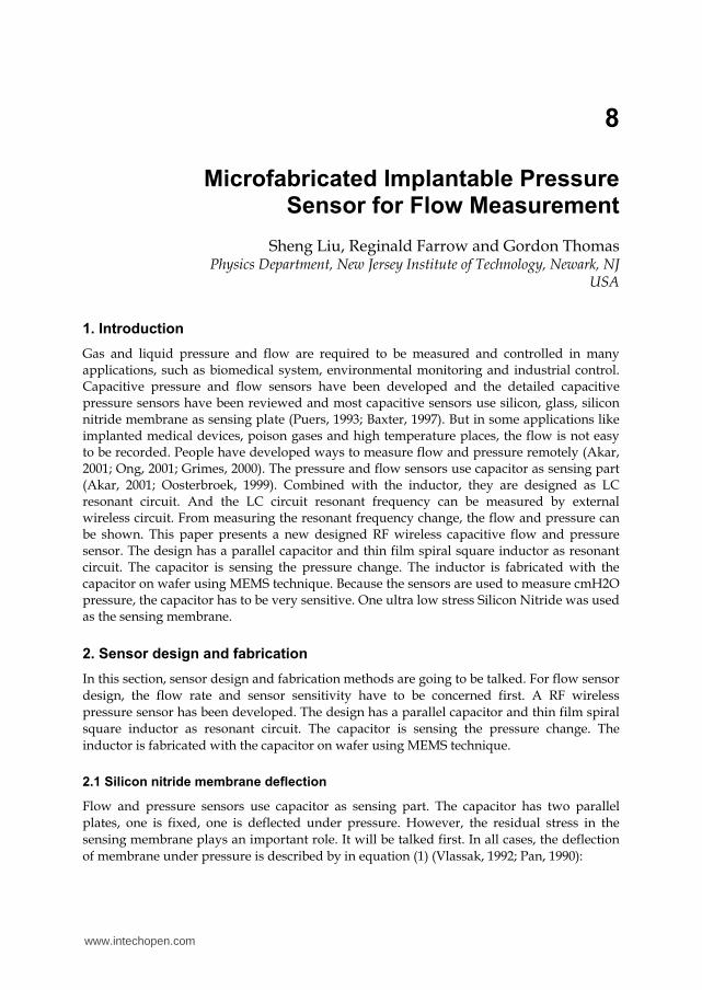
The full form of S is complicated, but in the region of deflection less than 5 microns shown
in Figure 1, the second term of displacement in Equation 1 is negligible and S is given just by the first term. Therefore,
2
01
aS
B t (6)
The main result here is that S decreases as the inverse of the residual stress, 0. Three values
of 0 are shown in Figure 1, where the inverse of the linear slopes is the membrane sensitivity.
The other result illustrated in Fig. 1 is that, if the residual stress were to approach zero, the sensitivity would be given by the inverse slope of the second term in Equation 1 that is cubic in In this case the sensitivity would be extremely high at low displacements tending toward infinity as the displacement approaches zero in the approximation of Equation (1).
0
1
2
3
4
5
0.0 2.0x10²
4.0x10²
6.0x10²
8.0x10²
1.0x10³
250 MPa
with dominent
residual stress
Pressure (Pa)
Mem
bra
ne d
efl
ecti
on
(m)
with no residual stress
100 MPa
150 MPa
Fig. 1. Computed results for the pressure related to two terms with and without residual stress of Equation 1 as a function of membrane deflection. The lower lines are proportional to the residual stress and are shown for 3 values of it. For higher residual stress, the sensitivity /d dP is smaller, as shown. The membrane sensitivity is proportional to the slope. With achievable value of residual stress, the first term dominates below about 5 microns, where increasing residual stress produces lower sensitivity. If the residual stress were negligible, the sensitivity would be determined by the slope of the second term and would be extremely high.
www.intechopen.com
Flow Measurement
172
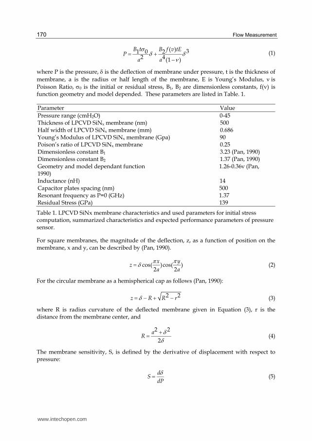
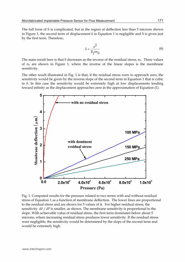
At small pressures according to Equation 6, the sensitivity is increased as the membrane dimension increases and as the thickness decreases. The computed results were plotted in Figure 2 and Figure 3.
50 100 150 200 250 3000
1
2
3
4
5 a=0.5 mm, t=500 nm
a=1 mm, t=500 nm
a=1.5 mm, t=500 nm
a=2 mm, t=500 nm
D
efl
ec
tio
n S
en
sit
ivit
y (m
/100P
a)
Residual Stress (MPa)
our value is 139 MPa
Fig. 2. The computed membrane sensitivity as function of residual stress for different film dimensions .
50 100 150 200 250 3000.0
0.4
0.8
1.2
1.6
our value is 139 MPa
a=0.5 mm, t=100 nm
a=0.5 mm, t=300 nm
a=0.5 mm, t=500 nm
Defl
ecti
on
Sen
sit
ivit
y (m
/100P
a)
Residual Stress (MPa)
Fig. 3. The computed membrane sensitivity as function of residual stress for different film thickness
www.intechopen.com
Microfabricated Implantable Pressure Sensor for Flow Measurement
173
(a)
(b)
0.0 0.1 0.2 0.3 0.4 0.5 0.6 0.70.0
0.2
0.4
0.6
0.8
1.0
Finite element model
Analytical model
No
mali
zed
defl
ecti
on
Distance from Center (mm) (c)
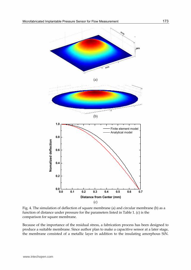
Fig. 4. The simulation of deflection of square membrane (a) and circular membrane (b) as a function of distance under pressure for the parameters listed in Table 1. (c) is the comparison for square membrane.
Because of the importance of the residual stress, a fabrication process has been designed to produce a suitable membrane. Since author plan to make a capacitive sensor at a later stage, the membrane consisted of a metallic layer in addition to the insulating amorphous SiN.
www.intechopen.com
Flow Measurement
174
The final membrane was designed as a tri-layer, mostly a 500nm thick a-SiN layer with a thin 10nm layer of Cr to improve adhesion of a thin 40nm layer of Ni. The finite element method (FEM) and theory results are shown in Figure 4. In Fig.4 (a), (b) the deep red color indicates the bigger deflection.
For square membrane, the capacitance can be computed out by integral Equation 7. .
100 00
10 00
cos( )cos( )2 2
a aC dS dx dyd gap z
a adx dyyx
gapa a
(7)
where is the dielectric constant, d is the distance of two plates, a is half width of membrane, gap is the distance between to plates as P=0, x and y are the distance from the membrane center.
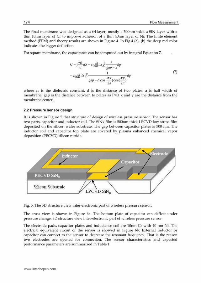
2.2 Pressure sensor design
It is shown in Figure 5 that structure of design of wireless pressure sensor. The sensor has two parts, capacitor and inductor coil. The SiNx film is 500nm thick LPCVD low stress film deposited on the silicon wafer substrate. The gap between capacitor plates is 500 nm. The inductor coil and capacitor top plate are covered by plasma enhanced chemical vapor deposition (PECVD) silicon nitride.
Fig. 5. The 3D structure view inter-electronic part of wireless pressure sensor.
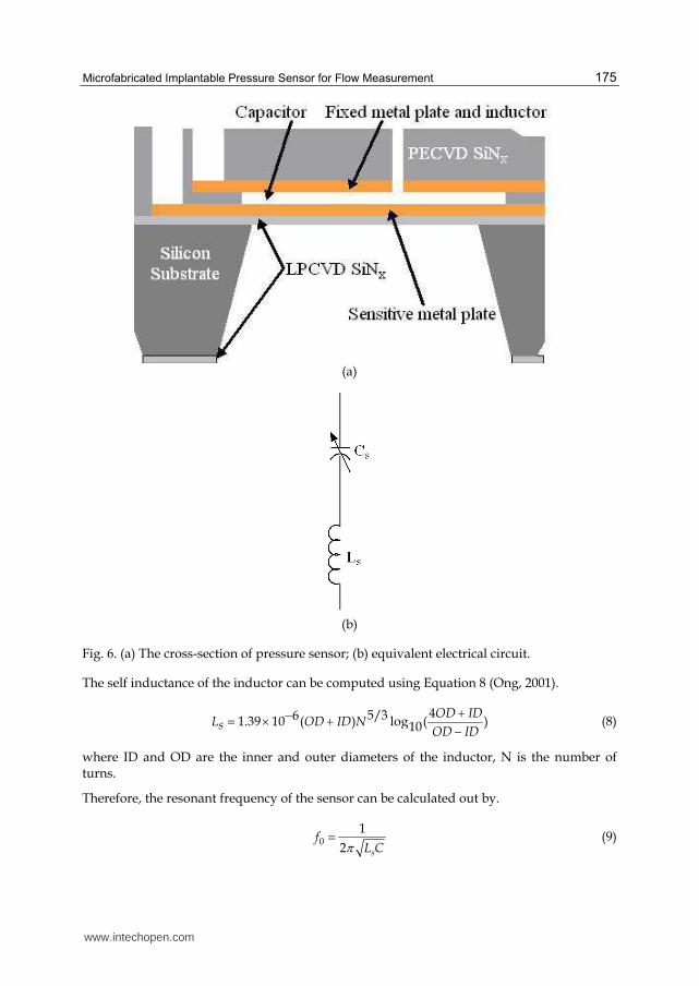
The cross view is shown in Figure 6a. The bottom plate of capacitor can deflect under pressure change. 3D structure view inter-electronic part of wireless pressure sensor
The electrode pads, capacitor plates and inductance coil are 10nm Cr with 40 nm Ni. The electrical equivalent circuit of the sensor is showed in Figure 6b. External inductor or capacitor can connect to the sensor to decrease the resonant frequency. That is the reason two electrodes are opened for connection. The sensor characteristics and expected performance parameters are summarized in Table 1.
www.intechopen.com
Microfabricated Implantable Pressure Sensor for Flow Measurement
175
(a)
(b)
Fig. 6. (a) The cross-section of pressure sensor; (b) equivalent electrical circuit.
The self inductance of the inductor can be computed using Equation 8 (Ong, 2001).
45/361.39 10 ( ) log ( )10OD ID
L OD ID NsOD ID
(8)
where ID and OD are the inner and outer diameters of the inductor, N is the number of turns.
Therefore, the resonant frequency of the sensor can be calculated out by.
0
1
2 s
fL C (9)
www.intechopen.com
Flow Measurement
176
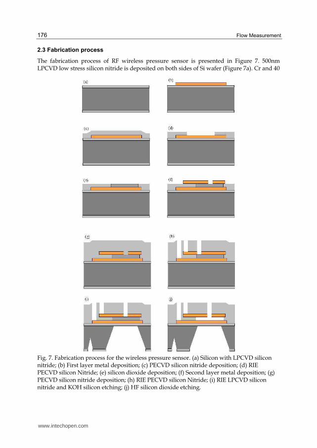
2.3 Fabrication process
The fabrication process of RF wireless pressure sensor is presented in Figure 7. 500nm LPCVD low stress silicon nitride is deposited on both sides of Si wafer (Figure 7a). Cr and 40
Fig. 7. Fabrication process for the wireless pressure sensor. (a) Silicon with LPCVD silicon nitride; (b) First layer metal deposition; (c) PECVD silicon nitride deposition; (d) RIE PECVD silicon Nitride; (e) silicon dioxide deposition; (f) Second layer metal deposition; (g) PECVD silicon nitride deposition; (h) RIE PECVD silicon Nitride; (i) RIE LPCVD silicon nitride and KOH silicon etching; (j) HF silicon dioxide etching.
www.intechopen.com
Microfabricated Implantable Pressure Sensor for Flow Measurement
177
nm Ni are deposited on a silicon wafer with 500 nm LPCVD low stress silicon nitride thin film (Figure 7b). PECVD silicon nitride is deposited on the metal for 750 nm as bottom plate of capacitor and electrode (Figure 7c). One window is opened by RIE and 500 nm SiO2 is deposited into the window (Figure 4d and Figure 7e). A thin metal film (50 nm) is then given as top plate of capacitor, inductor and electrode (Figure 7f). A PECVD silicon nitride protection layer (1 um) is then grown on the second metal layer (Figure 7g). Then reactive ion etching (RIE) method is used to etch the PECVD silicon nitride to open window for later etching silicon dioxide (Figure 7h). The back side window of silicon nitride film is etched and the silicon wafer is selectively etched with KOH and the etching stops on top LPCVD silicon nitride layer (Figure 7i). The final step is etching silicon dioxide with HF to open cavity for capacitor (Figure 7j).
3. Experimental results and discussion
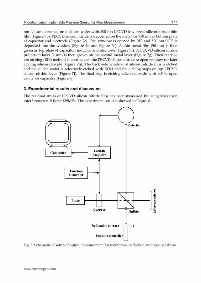
The residual stress of LPCVD silicon nitride film has been measured by using Mickleson
interferometer. It is 0=139MPa. The experiment setup is showed in Figure 8.
Fig. 8. Schematic of setup of optical measurement for membrane deflection and residual stress.
www.intechopen.com
Flow Measurement
178
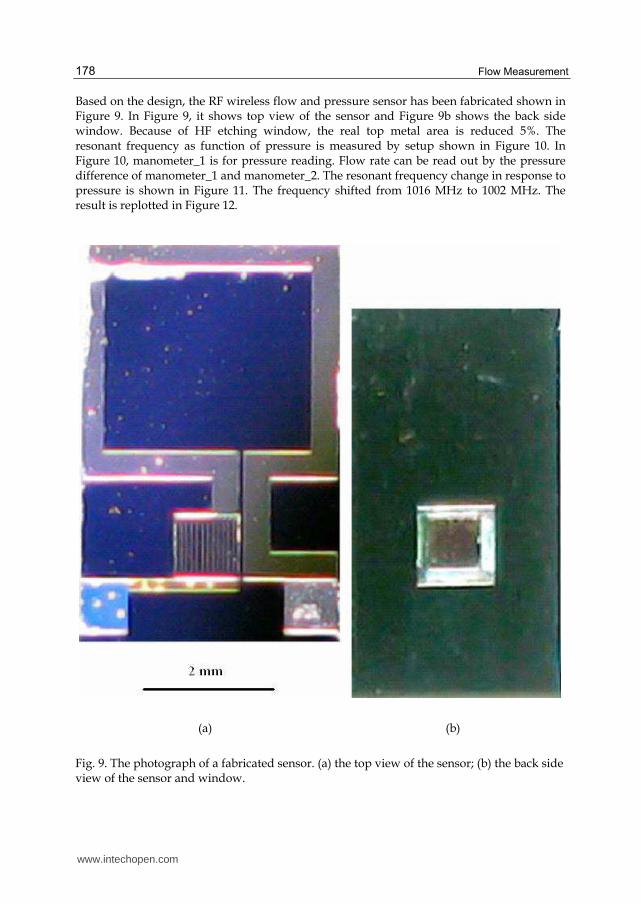
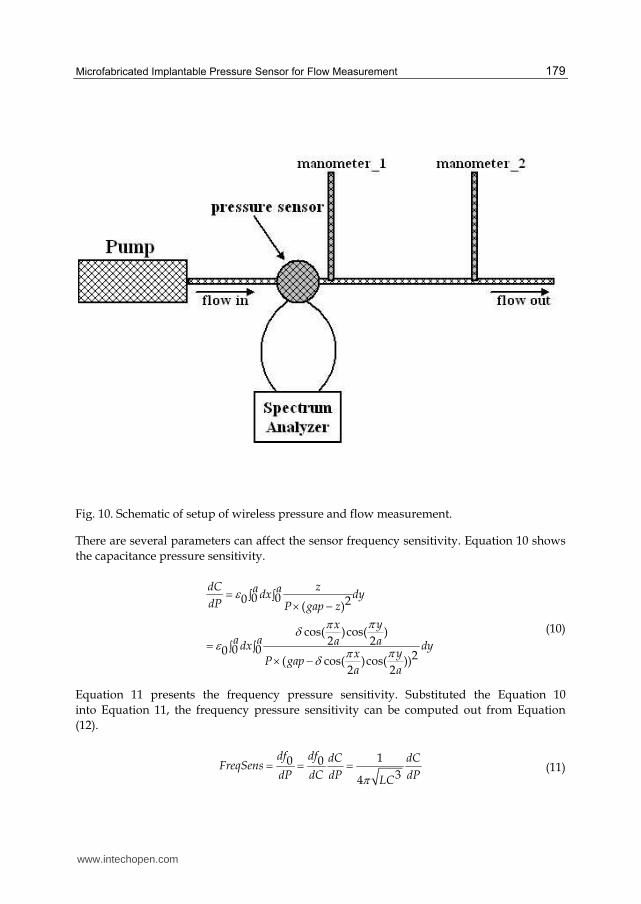
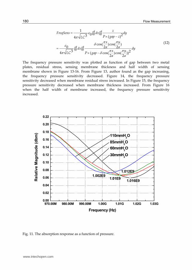
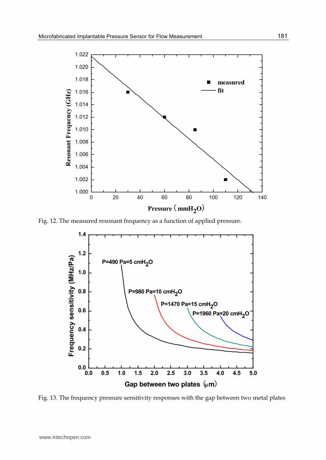
Based on the design, the RF wireless flow and pressure sensor has been fabricated shown in Figure 9. In Figure 9, it shows top view of the sensor and Figure 9b shows the back side window. Because of HF etching window, the real top metal area is reduced 5%. The resonant frequency as function of pressure is measured by setup shown in Figure 10. In Figure 10, manometer_1 is for pressure reading. Flow rate can be read out by the pressure difference of manometer_1 and manometer_2. The resonant frequency change in response to pressure is shown in Figure 11. The frequency shifted from 1016 MHz to 1002 MHz. The result is replotted in Figure 12.
(a) (b)
Fig. 9. The photograph of a fabricated sensor. (a) the top view of the sensor; (b) the back side view of the sensor and window.
www.intechopen.com
Microfabricated Implantable Pressure Sensor for Flow Measurement
179
Fig. 10. Schematic of setup of wireless pressure and flow measurement.
There are several parameters can affect the sensor frequency sensitivity. Equation 10 shows
the capacitance pressure sensitivity.
0 00 2( )
cos( )cos( )2 2
0 00 2( cos( )cos( ))2 2
dC za adx dydP P gap z
yx
a a a adx dyyx
P gapa a
(10)
Equation 11 presents the frequency pressure sensitivity. Substituted the Equation 10
into Equation 11, the frequency pressure sensitivity can be computed out from Equation
(12).
10 0
34
df df dC dCFreqSens
dP dC dP dPLC (11)
www.intechopen.com
Flow Measurement
180
10 00 23 ( )4
cos( )cos( )0 2 2
0 03 24 ( cos( )cos( ))2 2
za aFreqSens dx dyP gap zLC
yx
a a a adx dyyx
LC P gapa a
(12)
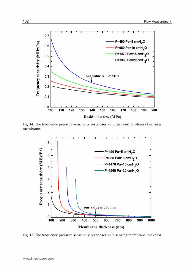
The frequency pressure sensitivity was plotted as function of gap between two metal
plates, residual stress, sensing membrane thickness and half width of sensing
membrane shown in Figure 13-16. From Figure 13, author found as the gap increasing,
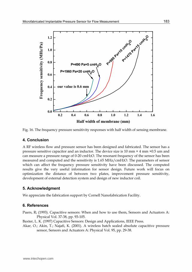
the frequency pressure sensitivity decreased. Figure 14, the frequency pressure
sensitivity decreased when membrane residual stress increased. In Figure 15, the frequency
pressure sensitivity decreased when membrane thickness increased. From Figure 16
when the half width of membrane increased, the frequency pressure sensitivity
increased.
970.00M 980.00M 990.00M 1.00G 1.01G 1.02G 1.03G0.00
0.02
0.04
0.06
0.08
0.10
0.12
0.14
0.16
0.18
0.20
0.22
1.016E9
1.012E9
1.01E91.002E9
Re
lati
ve
Ma
gn
itu
de
(d
bm
)
Frequency (Hz)
30mmH2O
60mmH2O
85mmH2O
110mmH2O
Fig. 11. The absorption response as a function of pressure.
www.intechopen.com
Microfabricated Implantable Pressure Sensor for Flow Measurement
181
0 20 40 60 80 100 120 1401.000
1.002
1.004
1.006
1.008
1.010
1.012
1.014
1.016
1.018
1.020
1.022
measured
fit
Reso
nan
t F
req
uen
cy (
GH
z)
Pressure (mmH2O)
Fig. 12. The measured resonant frequency as a function of applied pressure.
0.0 0.5 1.0 1.5 2.0 2.5 3.0 3.5 4.0 4.5 5.00.0
0.2
0.4
0.6
0.8
1.0
1.2
1.4
Fre
qu
en
cy
se
ns
itiv
ity
(M
Hz/P
a)
Gap between two plates (m)
P=490 Pa=5 cmH2O
P=980 Pa=10 cmH2O
P=1470 Pa=15 cmH2O
P=1960 Pa=20 cmH2O
Fig. 13. The frequency pressure sensitivity responses with the gap between two metal plates
www.intechopen.com
Flow Measurement
182
100 110 120 130 140 150 160 170 180 190 2000.0
0.1
0.2
0.3
0.4
0.5
0.6
0.7
P=490 Pa=5 cmH2O
P=980 Pa=10 cmH2O
P=1470 Pa=15 cmH2O
P=1960 Pa=20 cmH2O
Fre
qu
ency
sen
siti
vit
y (
MH
z/P
a)
Residual stress (MPa)
our value is 139 MPa
Fig. 14. The frequency pressure sensitivity responses with the residual stress of sensing membrane.
100 200 300 400 500 600 700 800 900 10000
1
2
3
4
5
6
P=490 Pa=5 cmH2O
P=980 Pa=10 cmH2O
P=1470 Pa=15 cmH2O
P=1960 Pa=20 cmH2O
Freq
uen
cy s
en
siti
vit
y (
MH
z/P
a)
Membrane thickness (nm)
our value is 500 nm
Fig. 15. The frequency pressure sensitivity responses with sensing membrane thickness.
www.intechopen.com
Microfabricated Implantable Pressure Sensor for Flow Measurement
183
0.2 0.4 0.6 0.8 1.0 1.2 1.4 1.60.0
0.2
0.4
0.6
0.8
1.0
1.2
P=1960 Pa=20 cmH2O
P=1
470
Pa=
15 c
mH 2
O
P=9
80 P
a=10
cm
H 2O
our value is 0.6 mm
Fre
qu
ency
sen
siti
vit
y (
MH
z/P
a)
Half width of membrane (mm)
P=490 Pa=5 cmH2O
Fig. 16. The frequency pressure sensitivity responses with half width of sensing membrane.
4. Conclusion
A RF wireless flow and pressure sensor has been designed and fabricated. The sensor has a pressure sensitive capacitor and an inductor. The device size is 10 mm × 4 mm ×0.5 um and can measure a pressure range of 0-20 cmH2O. The resonant frequency of the sensor has been measured and computed and the sensitivity is 1.65 MHz/cmH2O. The parameters of sensor which can affect the frequency pressure sensitivity have been discussed. The computed results give the very useful information for sensor design. Future work will focus on optimization the distance of between two plates, improvement pressure sensitivity, development of external detection system and design of new inductor coil.
5. Acknowledgment
We appreciate the fabrication support by Cornell Nanofabrication Facility.
6. References
Puers, R; (1993). Capacitive sensors: When and how to use them, Sensors and Actuators A: Physical Vol. 37-38, pp. 93-105.
Baxter, L. K. (1997) Capacitive Sensors: Design and Applications, IEEE Press. Akar, O.; Akin, T.; Najafi, K. (2001). A wireless batch sealed absolute capacitive pressure
sensor, Sensors and Actuators A: Physical Vol. 95, pp. 29-38.
www.intechopen.com
Flow Measurement
184
Ong, K. G.; Grimes, C. A.; Robbins , C. L.; Singh, R. S. (2001). Design and application of a wireless, passive, resonant-circuit environmental monitoring sensor, Sensors and Actuators A: Physical Vol.93, pp. 33-43.
Grimes, C. A.; Kouzoudis, D. (2000). Remote query measurement of pressure, fluid-flow velocity, and humidity using magnetoelastic thick-film sensors, Sensors and Actuators A: Physical Vol.84, pp. 205-212.
Oosterbroek, R. E.; Lammerink, T. S. J.; Berenschot, J. W.; Krijnen, G. J. M.; Elwenspoek, M. C.; Berg, A. van den. (1999). A micromachined pressure/flow-sensor, Sensors and Actuators A: Physical Vol.77, pp.167-177.
Vlassak, J.J.; Nix, W.D. (1992). A new bulge test technique for the determination of Young's modulus and Poisson's ratio of thin films, Journal of material research, Vol.7, pp. 3242-3249.
Pan, J. Y.; Lin, P.; Maseeh, F.; Senturia, S. D. (1990). Verification of FEM analysis of load-deflection methods for measuring mechanical properties of thin films, solid-State Sensor and Actuator Workshop, 4th Technical Digest., IEEE, pp. 70-73.
www.intechopen.com
Flow MeasurementEdited by Dr. Gustavo Urquiza
ISBN 978-953-51-0390-5Hard cover, 184 pagesPublisher InTechPublished online 28, March, 2012Published in print edition March, 2012
InTech EuropeUniversity Campus STeP Ri Slavka Krautzeka 83/A 51000 Rijeka, Croatia Phone: +385 (51) 770 447 Fax: +385 (51) 686 166www.intechopen.com
InTech ChinaUnit 405, Office Block, Hotel Equatorial Shanghai No.65, Yan An Road (West), Shanghai, 200040, China
Phone: +86-21-62489820 Fax: +86-21-62489821
The Flow Measurement book comprises different topics. The book is divided in four sections. The first sectiondeals with the basic theories and application in microflows, including all the difficulties that such phenomenonimplies. The second section includes topics related to the measurement of biphasic flows, such as separationof different phases to perform its individual measurement and other experimental methods. The third sectiondeals with the development of various experiments and devices for gas flow, principally air and combustiblegases. The last section presents 2 chapters on the theory and methods to perform flow measurementsindirectly by means on pressure changes, applied on large and small flows.
How to referenceIn order to correctly reference this scholarly work, feel free to copy and paste the following:
Sheng Liu, Reginald Farrow and Gordon Thomas (2012). Microfabricated Implantable Pressure Sensor forFlow Measurement, Flow Measurement, Dr. Gustavo Urquiza (Ed.), ISBN: 978-953-51-0390-5, InTech,Available from: http://www.intechopen.com/books/flow-measurement/microfabricated-implantable-pressure-sensor-for-flow-measurement

© 2012 The Author(s). Licensee IntechOpen. This is an open access articledistributed under the terms of the Creative Commons Attribution 3.0License, which permits unrestricted use, distribution, and reproduction inany medium, provided the original work is properly cited.