microelectronics lab elct605 spring 2018 digital lab
TRANSCRIPT
Microelectronics Lab
ELCT605
Spring 2018
Digital Lab
Session #6
VHDL
Driving BASYS 3 on-board 7 segment Display
Dr M. Abd El Ghany
Eng. Heba Elhosary
1

On-board Seven Segment Display
• Basys3 board has four digit common anode 7 segment displays that
can be driven grouped or individually.
Dr M. Abd El Ghany
Eng. Heba Elhosary
2
On-board Seven Segment Display
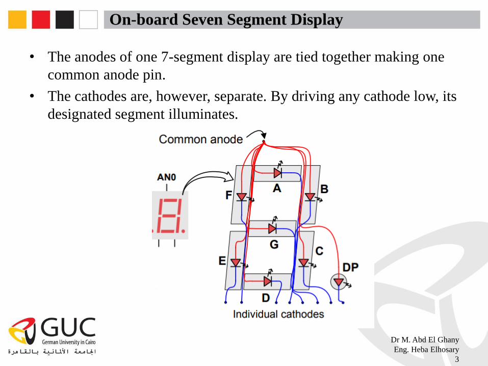
• The anodes of one 7-segment display are tied together making one
common anode pin.
• The cathodes are, however, separate. By driving any cathode low, its
designated segment illuminates.
Dr M. Abd El Ghany
Eng. Heba Elhosary
3

On-board Seven Segment Display
• 4 common anodes are available to drive the 4 seven segment
displays.
• Anodes should be driven low (not high!) to enable the 7 segment
display. This is because the anodes are connected to the collector of
pnp transistors. When the base is driven low, high voltage is received
at the anodes.
Dr M. Abd El Ghany
Eng. Heba Elhosary
4

On-board Seven Segment Display
• The cathodes are common to all displays. For example, all cathodes
of segment A from the 4 displays are tied together creating a CA
(common A cathode) to all the 4 displays.
• Depending on which display is enabled (its anode is driven low), the
specified segments of the enabled display illuminate.
Dr M. Abd El Ghany
Eng. Heba Elhosary
5
On-board Seven Segment Display
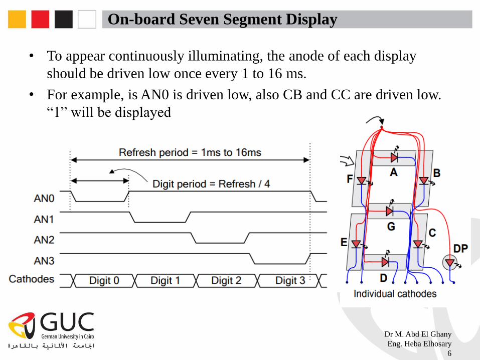
• To appear continuously illuminating, the anode of each display
should be driven low once every 1 to 16 ms.
• For example, is AN0 is driven low, also CB and CC are driven low.
“1” will be displayed
Dr M. Abd El Ghany
Eng. Heba Elhosary
6
Enabling on-board Seven Segment Display
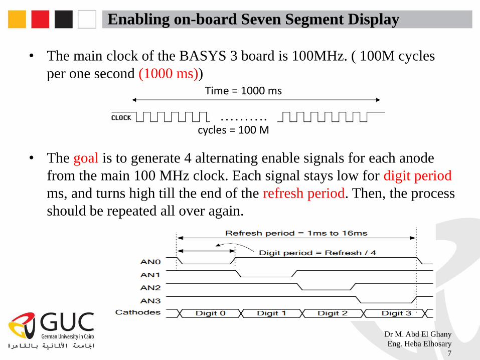
• The main clock of the BASYS 3 board is 100MHz. ( 100M cycles
per one second (1000 ms))
……….
• The goal is to generate 4 alternating enable signals for each anode
from the main 100 MHz clock. Each signal stays low for digit period
ms, and turns high till the end of the refresh period. Then, the process
should be repeated all over again.
Dr M. Abd El Ghany
Eng. Heba Elhosary
7
Time = 1000 ms
cycles = 100 M
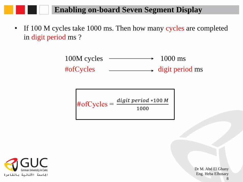
Enabling on-board Seven Segment Display
• If 100 M cycles take 1000 ms. Then how many cycles are completed
in digit period ms ?
100M cycles 1000 ms
#ofCycles digit period ms
#ofCycles =𝑑𝑖𝑔𝑖𝑡 𝑝𝑒𝑟𝑖𝑜𝑑 ∗100𝑀
1000
Dr M. Abd El Ghany
Eng. Heba Elhosary
8
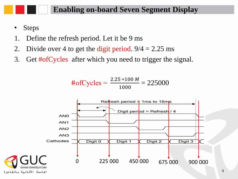
Enabling on-board Seven Segment Display
• Steps
1. Define the refresh period. Let it be 9 ms
2. Divide over 4 to get the digit period. 9/4 = 2.25 ms
3. Get #ofCycles after which you need to trigger the signal.
#ofCycles =2.25 ∗100𝑀
1000= 225000
9
0 225 000 450 000 675 000 900 000
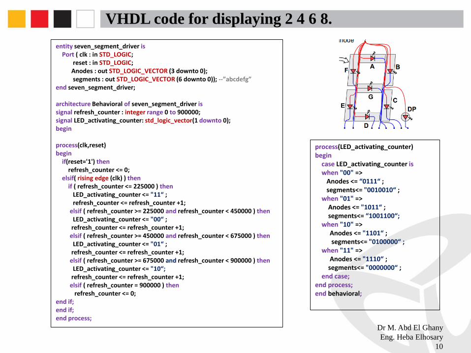
VHDL code for displaying 2 4 6 8.
Dr M. Abd El Ghany
Eng. Heba Elhosary
10
process(LED_activating_counter)begin
case LED_activating_counter iswhen "00" =>
Anodes <= “0111“ ; segments<= "0010010“ ;
when "01" =>Anodes <= "1011“ ; segments<= “1001100“;
when "10" => Anodes <= "1101“ ; segments<= "0100000“ ;
when "11" => Anodes <= "1110“ ; segments<= "0000000“ ;
end case;end process;end behavioral;
entity seven_segment_driver isPort ( clk : in STD_LOGIC;
reset : in STD_LOGIC;Anodes : out STD_LOGIC_VECTOR (3 downto 0);segments : out STD_LOGIC_VECTOR (6 downto 0)); --”abcdefg”
end seven_segment_driver;
architecture Behavioral of seven_segment_driver issignal refresh_counter : integer range 0 to 900000;signal LED_activating_counter: std_logic_vector(1 downto 0);begin
process(clk,reset)begin
if(reset='1') thenrefresh_counter <= 0;
elsif( rising edge (clk) ) thenif ( refresh_counter <= 225000 ) then
LED_activating_counter <= "11“ ; refresh_counter <= refresh_counter +1;
elsif ( refresh_counter >= 225000 and refresh_counter < 450000 ) then LED_activating_counter <= "00“ ;
refresh_counter <= refresh_counter +1; elsif ( refresh_counter >= 450000 and refresh_counter < 675000 ) then
LED_activating_counter <= "01“ ; refresh_counter <= refresh_counter +1;
elsif ( refresh_counter >= 675000 and refresh_counter < 900000 ) thenLED_activating_counter <= "10“;
refresh_counter <= refresh_counter +1;elsif ( refresh_counter = 900000 ) then
refresh_counter <= 0; end if;end if;end process;
Task 1
• Edit the code in the previous slide so that you can display your name
on the 4 displays. (if your name is too long to be displayed on 4
displays, display part of it, or any other name ). ☺
11
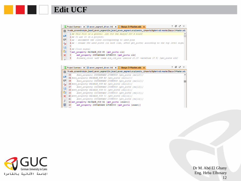
Edit UCF
Dr M. Abd El Ghany
Eng. Heba Elhosary
12

Dr M. Abd El Ghany
Eng. Heba Elhosary
13

Clock Dividers.
• How can you get 1 Hz clock from 100 MHz clock ?
…. ….
Toggle rate = 100 𝑀
𝑓𝑟𝑒𝑞/ 2
@ 𝑓𝑟𝑒𝑞 = 1 Hz : toggle rate = 50M (Toggle every 50M cycles)
Dr M. Abd El Ghany
Eng. Heba Elhosary
14
50 MHz / 500 ms 50 MHz / 500 ms
1 Hz / 1000 ms
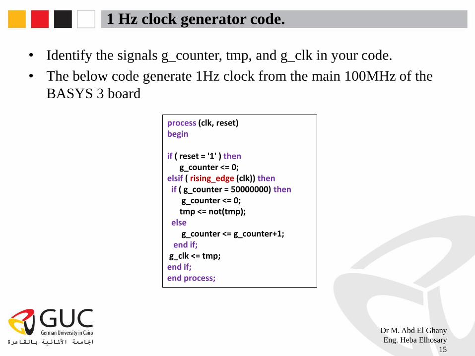
1 Hz clock generator code.
• Identify the signals g_counter, tmp, and g_clk in your code.
• The below code generate 1Hz clock from the main 100MHz of the
BASYS 3 board
Dr M. Abd El Ghany
Eng. Heba Elhosary
15
process (clk, reset) begin
if ( reset = '1' ) then g_counter <= 0;
elsif ( rising_edge (clk)) then if ( g_counter = 50000000) then
g_counter <= 0;tmp <= not(tmp);
elseg_counter <= g_counter+1;
end if;g_clk <= tmp;end if;end process;

Lab Task 2
• Connect the 4 bit FSM counter to the right most seven segment
display on the BASYS 3 board. The counter FSM frequency should
be 1 Hz.
• Hint : your code should have 6 processes.
• Recall : processes are concurrent (6 processes are operating in
parallel )
Dr M. Abd El Ghany
Eng. Heba Elhosary
16

Four bit Counter.
1. Generating 1Hz clock for the counter FSM.
2. Process for the state transition of the FSM
3. Process for the output of each state of the FSM
Dr M. Abd El Ghany
Eng. Heba Elhosary
17
1
2
3

Four bit Counter
4. Process for decoding the 4 binary bits to 7 segment display inputs.
Dr M. Abd El Ghany
Eng. Heba Elhosary
18
4
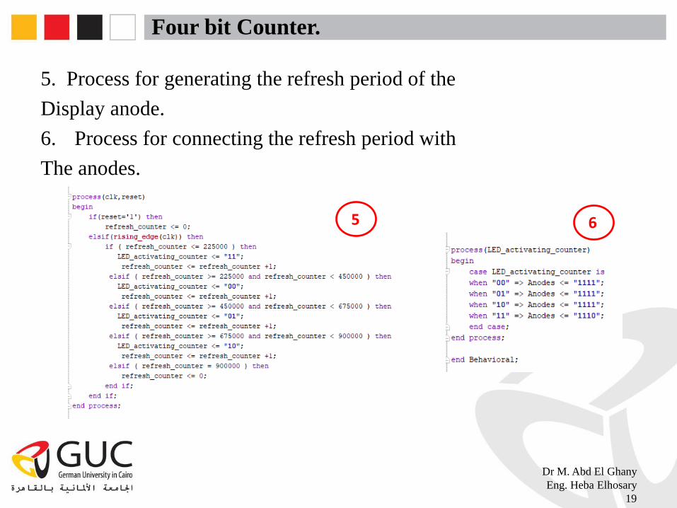
Four bit Counter.
5. Process for generating the refresh period of the
Display anode.
6. Process for connecting the refresh period with
The anodes.
Dr M. Abd El Ghany
Eng. Heba Elhosary
19
5 6

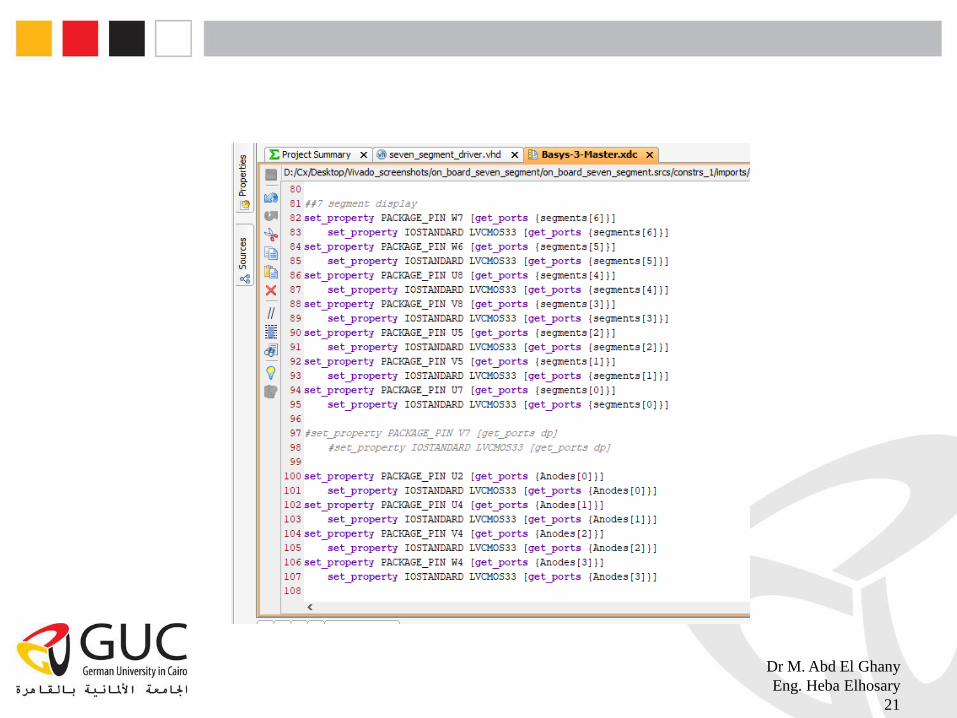
Edit UCF
Dr M. Abd El Ghany
Eng. Heba Elhosary
20
Dr M. Abd El Ghany
Eng. Heba Elhosary
21

Check timing constraints!
• The implemented task is supposed to be operating on 100MHz clock,
how ensure the implemented design can operate on such a high
frequency ?.
• Edit the timing constraints by entering the desired frequency. After
running the implementation, the timing report tells whether the user
specified timing constraints are met or not.
Dr M. Abd El Ghany
Eng. Heba Elhosary
22
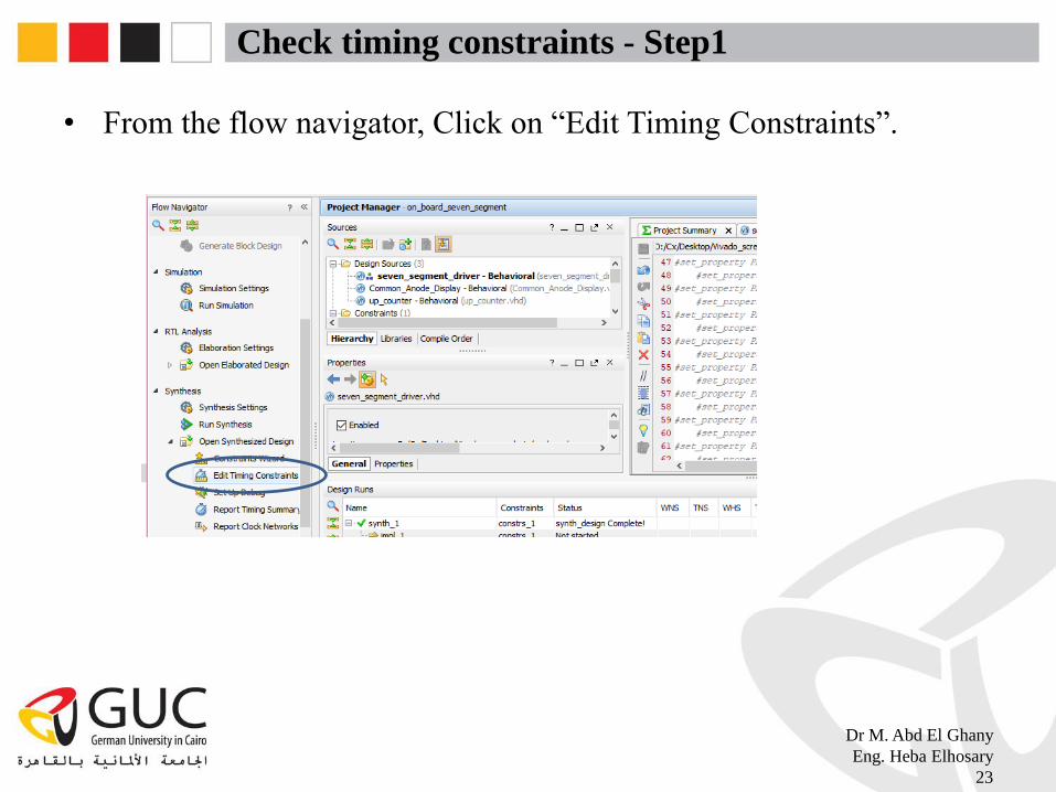
Check timing constraints - Step1
• From the flow navigator, Click on “Edit Timing Constraints”.
Dr M. Abd El Ghany
Eng. Heba Elhosary
23
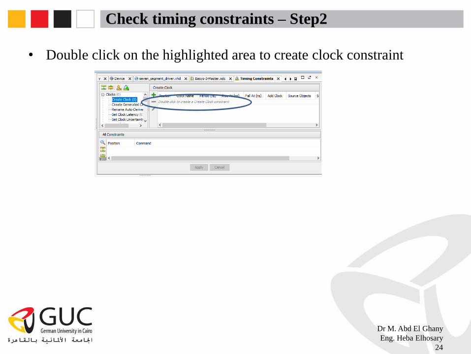
Check timing constraints – Step2
• Double click on the highlighted area to create clock constraint
Dr M. Abd El Ghany
Eng. Heba Elhosary
24
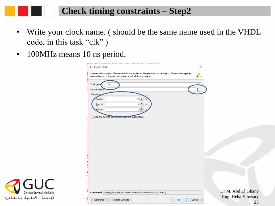
Check timing constraints – Step2
• Write your clock name. ( should be the same name used in the VHDL
code, in this task “clk” )
• 100MHz means 10 ns period.
Dr M. Abd El Ghany
Eng. Heba Elhosary
25

Check timing constraints – Step3
• Write your clock name. ( should be the same name used in the VHDL
code, in this task “clk” )
Dr M. Abd El Ghany
Eng. Heba Elhosary
26

Check timing constraints – Step3
• Click on “set”
Dr M. Abd El Ghany
Eng. Heba Elhosary
27

Check timing constraints – Step4
Dr M. Abd El Ghany
Eng. Heba Elhosary
28

Check timing constraints – Step5
• Click in the highlighted check box to add the created clock to your
design, click on “apply”, then ctrl+s to save the created constraints.
Dr M. Abd El Ghany
Eng. Heba Elhosary
29
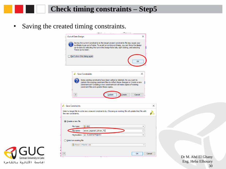
Check timing constraints – Step5
• Saving the created timing constraints.
Dr M. Abd El Ghany
Eng. Heba Elhosary
30
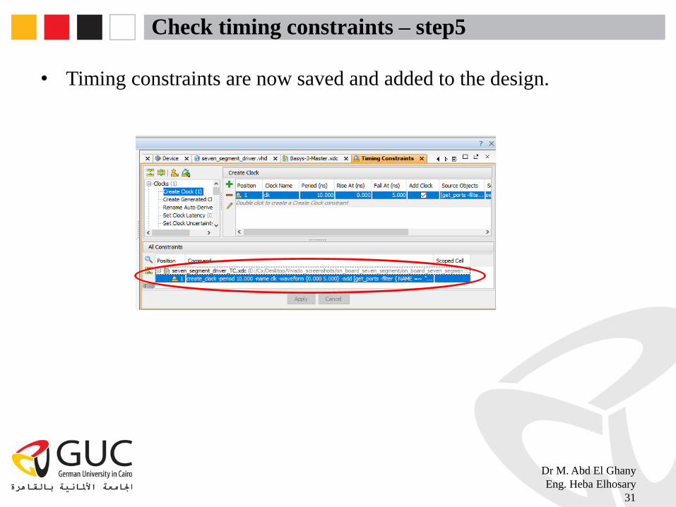
Check timing constraints – step5
• Timing constraints are now saved and added to the design.
Dr M. Abd El Ghany
Eng. Heba Elhosary
31

Check timing constraints
• Run implementation, then check the timing report to know if your
design meets the specified timing constraints or not.
Dr M. Abd El Ghany
Eng. Heba Elhosary
32

Check timing constraints
Dr M. Abd El Ghany
Eng. Heba Elhosary
33
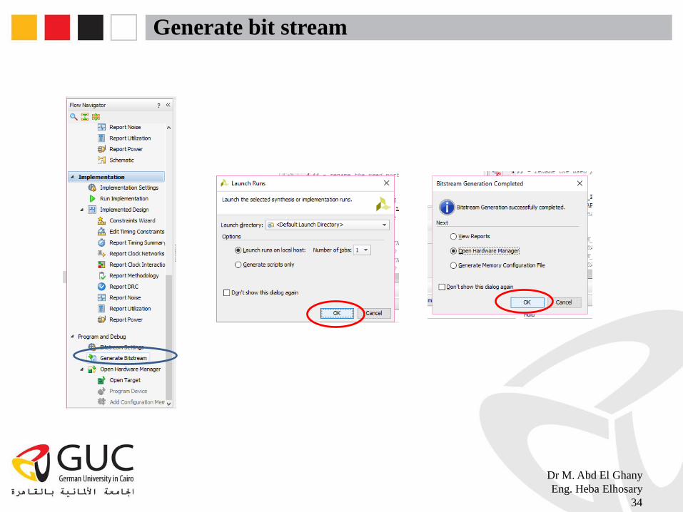
Generate bit stream
Dr M. Abd El Ghany
Eng. Heba Elhosary
34
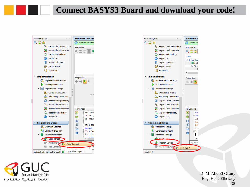
Connect BASYS3 Board and download your code!
Dr M. Abd El Ghany
Eng. Heba Elhosary
35
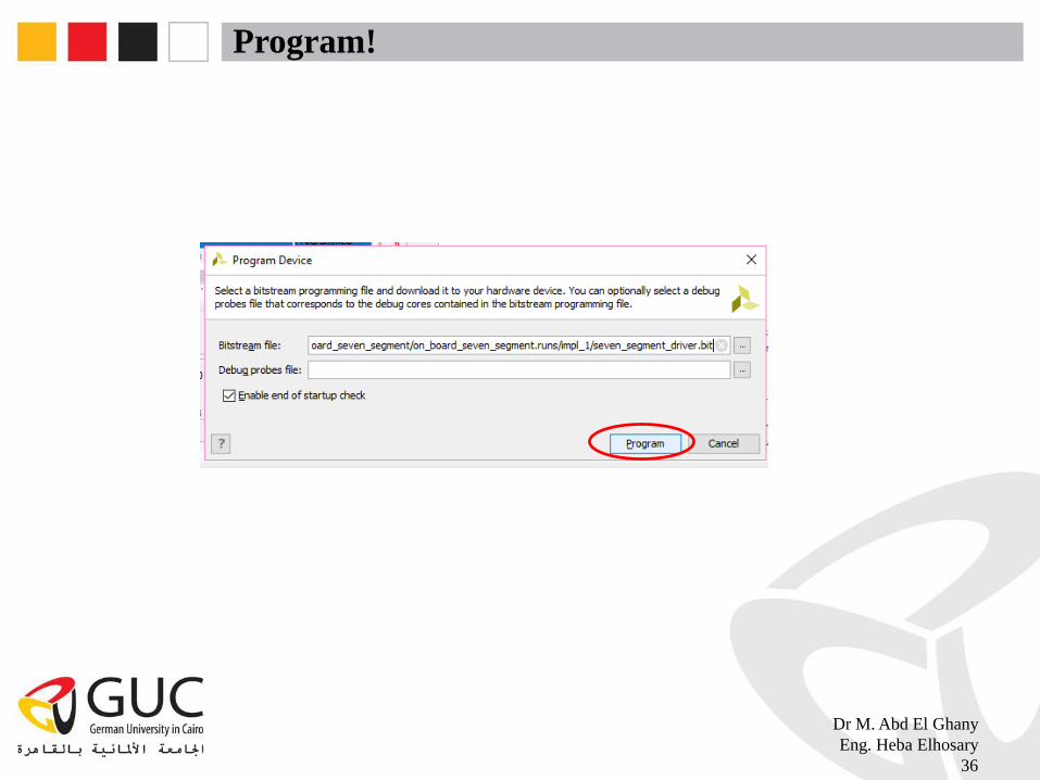
Program!
Dr M. Abd El Ghany
Eng. Heba Elhosary
36