michael tauberg - home automation system report
DESCRIPTION
Home Automation System in FPGA project reportTRANSCRIPT
Home Automation System in
FPGA
Project Report
Michael Tauberg
http://sites.google.com/site/michaeltauberg/
6/5/2010

Table of Contents1.0 Project Goal.....................................................................................................................................2
2.0 Project Motivation...........................................................................................................................3
3.0 Home Automation On the Web.......................................................................................................4
4.0 Home Automation Model for this Project.......................................................................................5
5.0 Home Automation Hardware Platform............................................................................................6
6.0 Demo Description..........................................................................................................................13
7.0 Leverage of Existing Projects.........................................................................................................21
8.0 Software Structure.........................................................................................................................23
9.0 Hardware Effort.............................................................................................................................23
10.0 Software Effort...............................................................................................................................24
11.0 Tools Used.....................................................................................................................................27
12.0 Goals Achieved..............................................................................................................................27
13.0 Conclusions....................................................................................................................................27
14.0 Appendix........................................................................................................................................28
Page 2 of 28

1.0 Project Goal
Main Project Goal
To create a functioning demonstration of a home automation system using real hardware to simulate home control features and custom software to control these features
The Home Automation demo should showcase some of the possibilities of home automation in a model environment
Additional Goals
To use a web server application as the main interface for home control
To implement a Real Time Operating System capable of providing home services simultaneously
To have a scalable project upon which additional home control features can be added in the future
To build additional hardware circuits and integrate them into the home control model
2.0 Project Motivation
Homeowners constitute one of the biggest consumer markets. As such, any product that is targeted to homeowners could generate considerable revenue and has great potential for growth. We therefore believe that Home Automation systems have the potential to be very profitable in the future
Why Home Automation?
With the advance of integrated computer technology, at least half of household products purchased are electronic devices of some sort. These electronic devices each come with individual controls that do not interface with each other and quickly become cumbersome to use. Device controls come in different styles but with very common functions as shown in Figure 1. Having multiple controls can be complicating especially when common buttons do not follow a standard nomenclature. This growing complexity begs for an integrated and centralized home control solution
Page 3 of 28
Figure 1: Different Styles of Device Controls
Centralized, easy to use home control can be accomplished through a Home Automation System.
One can imagine the multitude of possibilities with an integrated Home Automation System. Through the use of a single control center, a homeowner can setup and manipulate controls for many different house features as shown in figure 2. For example, house lights can be dimmed using a single control system from anywhere in the house or while watching a movie.
Figure 2: Home Automation Equipment Control Diagram
Or imagine that you need to water the grass. Well why not use the main control remote to activate the sprinkler system. How about some popcorn while watching TV? Just use the remote to view your
Page 4 of 28

grocery inventory to check if you have popcorn. An automated home system can be expanded even further by connecting the system to the internet. This will give homeowners the ability to check the status of their house even while they are not there. Can’t remember if the garage door was left open or the oven was left on? Don’t waste time going home or worrying about it all day. With a home automation system, one can check online to see the status or change the status of things like the garage, oven, or any number of other appliances.
3.0 Home Automation On the Web
Home automation has been around for several years now but the proliferation of smartphones has allowed for a universal, web capable control for home automation features. These smartphones are poised to become the hub through which all home automation control is done.
There are already many application created for use on iphone, android, and blackberry that target the home automation market. Here is a link to a page which provides a list of 50 different home automation apps for the iphone:
http://itunes.apple.com/app/cf-iviewer/id285304607?mt=8 http://www.cocontech.com/portal/ component/content/article/77-the-ultimate-list-of-iphone-home-automation-applications?start=1
4.0 Home Automation Model for this Project
The Home automation model for this project consists of multiple home control features connected to a central control unit. As stated in the Motivation section, many home features can be chosen for automation; however only a subset was chosen for implementation in this project. The features that were chosen are shown in the diagram below.
Figure 3: Home Automation Functional Model
Page 5 of 28

These features include:
Remote web connection Multimedia center control - upload photos, videos etc to home device House light control – turn on/off and dim home lights House clock control – read and set home clocks Temperature meter – read home temperature Power meter – read home power consumption Security system – read home security sensors Climate control – set home thermostat to turn on/off heat and AC
There are two external interfaces to the home control unit of this model. These are:
Local terminal connection Remote Web Connection
The local connection provides a terminal interface to a user who is physically in the home and wants a centralized control panel. For example, this interface could be integrated into a digital thermostat except that it would also grant access to all other home features listed in the model
Page 6 of 28

The remote connection allows a user to access the Home Automation System even when not physically in the home. For example, the Home Control Unit could be connected to a web server which would upload and download information from a remote user. This would allow for home control from any web enabled device including home PCs, work PCs or mobile internet devices (iPhones, Blackberries etc).
5.0 Home Automation Hardware Platform
This section describes how the home automation model features described in the previous section are mapped to real hardware for the demonstration.
5.1 SmartFusion Evaluation Board Overview
The hardware platform chosen to model the home automation system was the the Actel SmartFusion Evalutaion Board. An Actel FPGA with a hardened ARM Cortex-M3 processor is a the heart of the board and is used to run all of the Home Automation System Software. As such, the Actel FPGA serves as the Home Control Unit shown in the Home Automation Model (fig 3). In addition to providing a strong processor, the SmartFusion evaluation board also provides board peripherals that were needed to model the home features discussed in the Model section of this document. Finally, the Actel board came with free design software that allowed for fast software and hardware system devlopement. A diagram of the Actel SmartFusion Evalidation Kit is shown below
Figure 4: SmartFusion Evaluation kit (P/N: A2F-EVAL-KIT)
Page 7 of 28
5.2 SmartFusion Board FPGA in Detail
At the heart of the board is the Actel SmartFusion FPGA which contains multiple hardened cores that are needed for communicating with external peripherals. A block diagram of the Actel FPGA is shown below in fig 5
Figure 5: SmartFusion FPGA Block Diagram
The main processing unit of the Actel FPGA is the ARM Cortex-M3 processor (1). The Cortex-M3 is a 32-Bit ARM processor that can run at 100 MHz (2) in the FPGA. The Cortex-M3 internal processor can access 256 Kbytes of Embedded Nonvolatile Flash memory (2) and 64kbytes of internal SRAM.
The FPGA also includes hardened programmable analog circuitry including 2 ADCs that can operate in 12-bit mode and a digital analog processing engine that processes analog samples
5.3 SmartFusion Evaluation Board Circuits
Page 8 of 28

The SmartFusion Board has multiple circuits that are used to model the home automation features. These circuits are discussed below.
A current sensing circuit that is controlled by a thumbwheel pot on the board is shown below. This circuit is used for modeling the Power Meter Feature.
Figure 6: Current Sensing Circuit
There are 2 board push button circuits connected to the Actel FPGA as shown in the figure below. The push buttons are used to model the Security System feature and simulate an intruder alert whenever they are pressed
Figure 7: Push-Button Switch circuit
There are 8 LEDs on the board that can be turned on/off using the Actel FPGA. The LED circuitry consists of forward biasing these LEDs to turn them on. The LEDs are used to model the Light Control Feature.
Figure 8: LED Circuit
The OLED display on the board is a low-power display that uses 3.3V and 10V power supplies (1). The display is controlled by and I2C bus interface. The OLED can display any pixilated image programmed onto it and is used to model the Multimedia Control Feature. Figure 9 shows the circuit used for the display.
Page 9 of 28

Figure 9 OLED display circuits
There is also a temperature monitoring circuit on the board that uses a temperature diode to measure ambient room temperature (1). The temperature is calculated by measuring the current through the diode. The temperature circuit is used to model the Temperature Meter Feature.
Figure 10: Temperature Circuit
5.4 Mapping of SmartFusion Board Components to Home Automation Model
Ethernet Interface
the SmartFusion FPGA on the board contains a hardened MAC layer processor that is used to send ethernet data to and from the Cortex-M3 processor. This Ethernet controller is connected to an RJ45 connector on the board which was in turn is connected to a LAN. With the connection between the Cortex-M3 system and the LAN established, a PC on the LAN is able to access web pages hosted by the Cortex-M3 system, fig 11 shows the setup used.
Page 10 of 28

Figure 11: Home Automation Setup Front and Back view
In the figure about we can see the SmartFusion Evaluation board (hosting the web server software) in the center. It is attached to the model home which also includes external fan and buzzer circuits. The SmartFusion board is connected to both a laptop (on the left) and a router on the right. The router acts as a Local Area Network on which other devices can connect. The Laptop is connected to this router wirelessly. Once connected to the LAN, the SmartFusion board running web server software requests an IP address on the LAN. The router provides the IP and the FPGA hosts the Home Automation web pages. Any device on the LAN (the laptop) can then access these web pages.
Conceivably, the router could be connected to the internet so that any device on the internet could access these Home Automation pages.
UART interface
A USB-to-UART chip on the board allows for communication between a PC and the Cortex-M3 UART via a USB cable. This UART interface allows the Cortex-M3 to send and receive data to a PC Hyperterminal and is used to model the Local Terminal Connection shown in fig 3 of this documents
OLED Display
Page 11 of 28

An OLED display on the board communicates with the Cortex-M3 system via an I2C bus. This display can display images programmed by the Cortex-M3 system and is used to model a digital picture frame. The OLED models the Multimedia Control feature shown in fig 3 of this document
Board LEDs
Board LEDs can be turned on/off using GPIO from the Cortex-M3 system. They are used to model the Light Control feature shown in fig 3 of this document.
Real Time Clock
The Actel SmartFusion FPGA contains an internal Real Time clock that can be set by the Cortex-M3 system. This real time clock models the Clock Control feature shown in fig 3 of this document.
Push Button Switches
There are 2 Push button switches on the board connected to GPIO on the Cortex-M3 system. These push button switches are used to generate interrputs in the Cortex-M3 system which alerts the user to the fact that they have been pressed. These switches model the Security System feature shown in fig 3 of this document.
Current and Voltage Monitor
The board has a built in current monitoring circuit that is used to montor the current drawn by is an adjustable thumbwheel POT circuit. The board also has a voltage monitor that measures the voltage of the POT circuit. Together, these monitors are combined to provide the wattage of the circuit and thus model the Power Meter Feature shown in fig 3 of the document. Power consumption can be varied by turning the thumbwheel POT.
Temperature Monitor
The board temperature monitor circuit relays ambient room temperature to the SmartFusion FPGA. This monitor is used to model the Temperature Meter feature shown in fig 3.
5.5 External Circuits
In addition to the circuits that come with the Actel SmartFusion Evaluation Kit, we designed an external circuit to simulate home fan and buzzer. This circuit is shown below.
Figure 12: External Circuit control
Page 12 of 28

The external circuit is made up of a NPN transistor used as a switch. When voltage is applied to the transistor base, the transistor turns on activating the component attached in the emitter side (fan or buzzer). The transistor base is wired to a GPIO on the SmartFusion Evaluation kit, allowing the FPGA to control the Fan and the buzzer in software.
6.0 Demo Description
The Home Automation demo can operate in 2 modes. These are
Local Terminal Mode Remote Web server Mode
6.1 Home Terminal Mode
In terminal mode, the Actel FPGA system prints a menu to a user HyperTerminal over a UART interface. This menu is active upon board power up and serves as the main portal to the home control features. Fig 13 below shows the main terminal page upon power
Figure 13: HyperTerminal Menu
Page 13 of 28

As seen above, the user can select six options from the Main menu. These options are discussed below
0 – Upload Digital Picture Frame
This selection models a user uploading an image to a digital picture frame. In the actual project, a user types in a message and this messages is programmed onto the board OLED display.
1 – Turn Lights ON/OFF
This selection models the capability to control home lights. When selected, the prints out which board LEDs are on and gives the user the ability to turn on/off any LED. This is shown in the figure below
Figure 14: Lights in Terminal Mode
2 – Read Thermostat
This selection models home thermostat control. When selected, the system reads the board temperature and prints the value in degrees Celsius. This can be seen in the figure below
Page 14 of 28
Figure 14: Thermostat in Terminal Mode
3 – Read Power Meter
This selection models home power meter. When selected, the system reads the power consumption of the board thumbwheel POT circuit and prints the value in watts. This can be seen in the figure below. The power measured can be varied by turning the POT.
Figure 15: Thermostat in Terminal Mode
4 – Check Home Security
This selection models home security sensors. When selected, the user will be prompted on whether or not they want home security to be turned ON/OFF. If security is enabled, then pushing either of t he board LEDs will generate an interrupt and a security warning message will be printed to the terminal. This is shown in the figure below
Figure 16: Security in Terminal Mode
Page 15 of 28

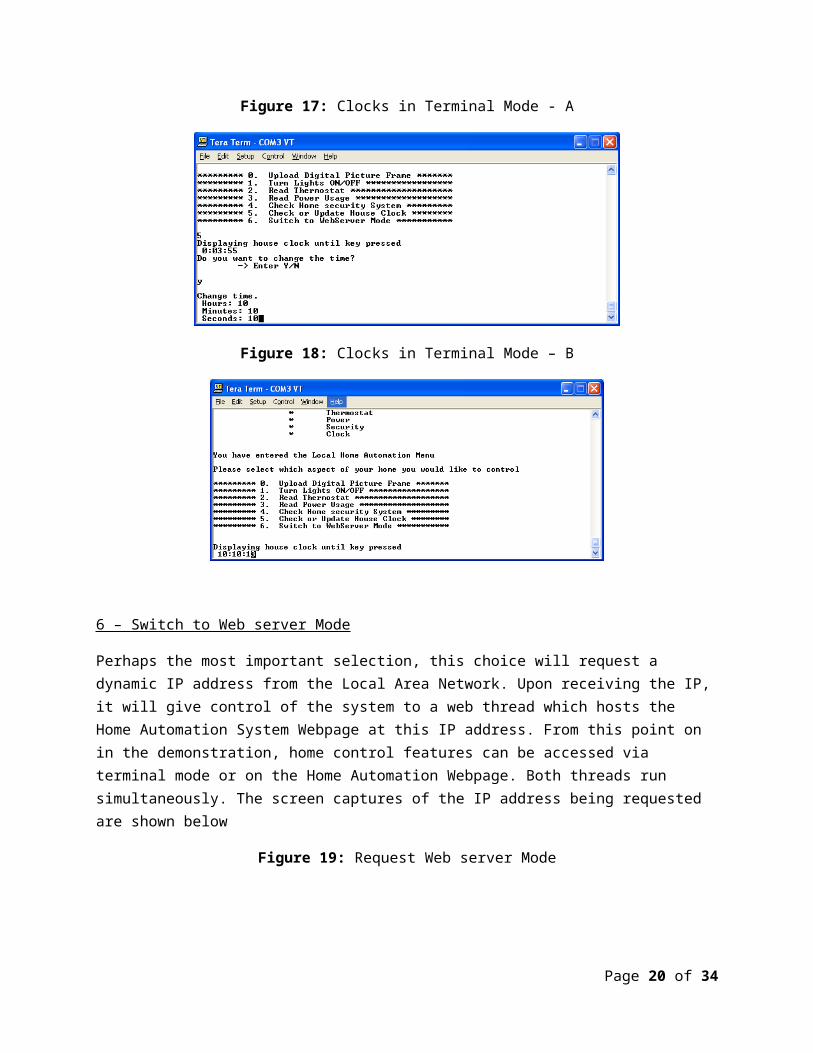
5 – Check or Update House Clock
This selection models home clock control. When selected, t he terminal will print the value of the Real-Time-Clock inside the FPGA system. After printing the clock value, the user will be prompted to change the clock value. If they choose to change the clock value, a new clock value will be read then next time this option is selected. This is shown in the figures below
Figure 17: Clocks in Terminal Mode - A
Figure 18: Clocks in Terminal Mode – B
Page 16 of 28

6 – Switch to Web server Mode
Perhaps the most important selection, this choice will request a dynamic IP address from the Local Area Network. Upon receiving the IP, it will give control of the system to a web thread which hosts the Home Automation System Webpage at this IP address. From this point on in the demonstration, home control features can be accessed via terminal mode or on the Home Automation Webpage. Both threads run simultaneously. The screen captures of the IP address being requested are shown below
Figure 19: Request Web server Mode
Note: HyperTerminal mode continues to be operational after switching to web server mode
6.2 Home Automation Web server Mode In web server mode, the Actel FPGA system runs web server code to display a main Home Automation System webpage to the user. This page demonstrates how home automation control can be accomplished remotely from the web. Figure 17 shows the webpage mode tree diagram.
Figure 20: Main Web Page Tree Diagram
Page 17 of 28
Automated Home System Main Web page
Light Control
Power meter
Thermostat Display
Digital Picture Display
Fan On/Off
Display Time
Control in different locations
PG&E monitoring
system
HeaterAir Conditioner
Picture Album
Selection
Clock Control
Fan Control

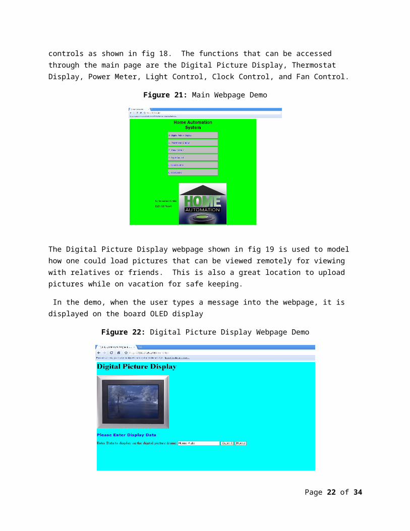
The main webpage demo page is the home webpage. From this webpage a user can select the desired button to access the home automated controls as shown in fig 18. The functions that can be accessed through the main page are the Digital Picture Display, Thermostat Display, Power Meter, Light Control, Clock Control, and Fan Control.
Figure 21: Main Webpage Demo
The Digital Picture Display webpage shown in fig 19 is used to model how one could load pictures that can be viewed remotely for viewing with relatives or friends. This is also a great location to upload pictures while on vacation for safe keeping.
In the demo, when the user types a message into the webpage, it is displayed on the board OLED display
Figure 22: Digital Picture Display Webpage Demo
Page 18 of 28

The temperature can be controlled through the Thermostat Temperature Monitor webpage. Accessing this webpage displays the temperature value read from the board
Figure 23: Thermostat Temperature Monitor Webpage Demo
When the Power meter webpage (fig 21) is accessed, the power consumed by the POT circuit is displayed. This could be used to showcase how it might be time to turn off some unnecessary appliances especially during the summer to avoid power outages.
Figure 24: Power Monitor Webpage Demo
Page 19 of 28
House lights modeled by board LEDs can be turned off/on from the house light monitor webpage shown in fig 22.
Figure 25: House Light Monitor Webpage Demo
The house clock webpage will tell the user the current time (measured by FPGA RTC). Although simple, this webpage can be expanded to show other house timers and or timestamp house events.
Figure 26: House Clock Monitor webpage Demo
Page 20 of 28

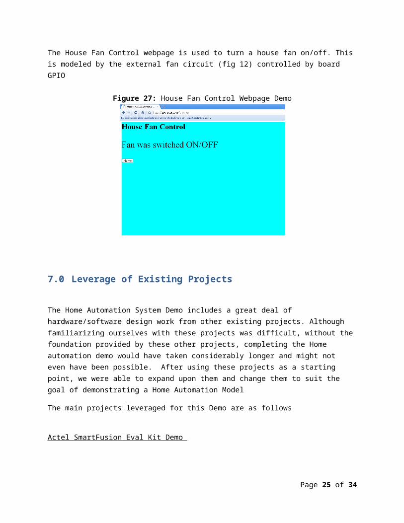
The House Fan Control webpage is used to turn a house fan on/off. This is modeled by the external fan circuit (fig 12) controlled by board GPIO
Figure 27: House Fan Control Webpage Demo
7.0 Leverage of Existing Projects
The Home Automation System Demo includes a great deal of hardware/software design work from other existing projects. Although familiarizing ourselves with these projects was difficult, without the foundation provided by these other projects, completing the Home automation demo would have taken considerably longer and might not even have been possible. After using these projects as a starting
Page 21 of 28
point, we were able to expand upon them and change them to suit the goal of demonstrating a Home Automation Model
The main projects leveraged for this Demo are as follows
Actel SmartFusion Eval Kit Demo
The Actel SmartFusion Eval Kit Demo provided the following components needed for our project (8)
1) Hardware configuration of the Actel FPGA including configuration of:a. Memory Controllerb. Analog Processing Enginec. GPIOd. Ethernet Controllere. I2C interface
2) Software project with settings to match the hardware project, used as the basis for the development
3) Firmware drivers for Actel FPGA components including:a. Analog Processing Engineb. Ethernet Controllerc. GPIOd. I2C e. UART
4) Key firmware includinga. OLED device driverb. Basic FreeRTOS application including port to Cortex-M3 processorc. uIP Web server application code integrated with Ethernet controller
FreeRTOS STM32 Cortex-M3 Project
FreeRTOS was the Real Time Operating System implemented in the Home Automation project. Use of the RTOS and its porting to a Cortex-M3 processor were demonstrated by this project (5). This project demonstrates the creation of OS tasks and demonstrates how they are scheduled
uIP Web Server
Both projects listed above made use of the open source uIP web server. This web server project contains the TCP/IP layer firmware (7) and was used as a reference to understand how uIP implements a web server application
Page 22 of 28

8.0 Software Structure
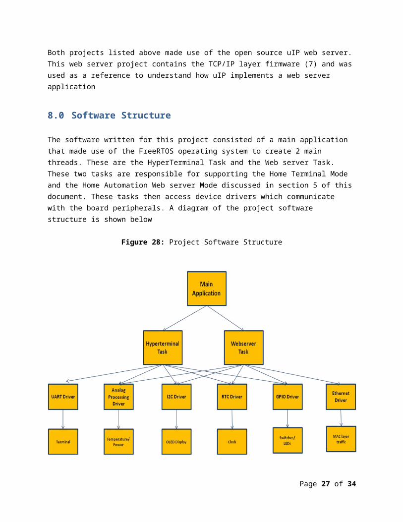
The software written for this project consisted of a main application that made use of the FreeRTOS operating system to create 2 main threads. These are the HyperTerminal Task and the Web server Task. These two tasks are responsible for supporting the Home Terminal Mode and the Home Automation Web server Mode discussed in section 5 of this document. These tasks then access device drivers which communicate with the board peripherals. A diagram of the project software structure is shown below
Figure 28: Project Software Structure
Note: Not included in this diagram is the Analog processing task which continuously read analog values
9.0 Hardware Effort
Hardware effort for this project consisted of modifying the Actel SmartFusion web demo to suit the needs of our application. We added additional fan and buzzer circuitry external to the board and this had to reconfigure the FPGA GPIO settings to target the pins we used for these circuits. Fig 26 below shows the changes made to the GPIO block in Actel SmartDesign software
Page 23 of 28

Figure 29: SmartDesign Hardware Changes
After making the above changes to the hardware project, HDL was generated by SmartDesign. This HDL was then taken through the Actel Libero tool flow (SmartDesign-> Synplify Synthesis->Designer P+R->FlashPro Programming File generation)
The final programming file was used to program the FPGA with a hardware design which supported our external circuits
10.0 Software Effort
Early in the project development, we downloaded the Actel SmartFusion demo and found that it would provide a good development platform for our home automation system demo. Crucially, this project had implemented a web server on top of an RTOS which were 2 key requirements of our project. After studying the demo in great detail, we discovered how each software layer (application/rtos/web server/drivers) worked and began to look for ways to use these features in a home automation system. Below are descriptions of changes made to this software project for our Home Automation Demo
Page 24 of 28
1) Changing RTOS tasks
We needed the application HyperTerminal mode to be active at the same time as the demo web server mode to simulate how a real control system would operate. This was done by changing the interaction of the RTOS tasks so that both could operate at the same time with the HyperTerminal task having a higher priority. These tasks are created in the “main.c” software project file
2) Development of HyperTerminal Mode
To simulate a local control panel of a home automation system, we had to write application code that would allow home control features to be accessed via a HyperTerminal window. This was accomplished by creating a menu system which allowed control of all home features from the terminal. This code is visible in the “hyperterminal_task.c” file in the software project
3) Create Home Automation Demo WebPages
In order to access home features from the web, we created html pages that would be hosted on the web that would provide a status of home features as well as allow a user to change the home status. These web pages are visible in the “webserver\httpd-fs” folder in the project
4) Integrating Demo WebPages
These home automation web pages had to be stored in the software project in order for them to be integrated into the web server. This was accomplished in 2 steps. In the first step, all web server .htm and .jpeg files were run through a perl script that was part of the uIP project. This script is called “makefsdata” and is in the web server folder of the software project. After using the script to convert the web files to hexadecimal data, this data was copied into the web server project “httpd-fsdata.h” file in the web server project.
Now, the project contains the necessary web pages, but we still had to create the code to provide dynamic data from the web pages as well as read data inputted from the web. This code is visible in the “httpd-cgi.c” file of the webserver folder. Here is the simple light (LED) demo example from the project in the httpd-cgi.c file.
gpio_pattern = MSS_GPIO_get_outputs();
/*turn on/off main light at GPIO15*/gpio_pattern ^= 0x8000;MSS_GPIO_set_outputs( gpio_pattern );
if ((gpio_pattern & 0x01) == 0) sprintf(light_string1,"Light 1 is on \n\r"); if ((gpio_pattern & 0x02) == 0) sprintf(light_string2,"Light 2 is on \n\r"); if ((gpio_pattern & 0x04) == 0) sprintf(light_string3,"Light 3 is on \n\r"); if ((gpio_pattern & 0x08) == 0) sprintf(light_string4,"Light 4 is on \n\r"); if ((gpio_pattern & 0x10) == 0) sprintf(light_string5,"Light 5 is on \n\r"); if ((gpio_pattern & 0x20) == 0) sprintf(light_string6,"Light 6 is on \n\r");
Page 25 of 28

if ((gpio_pattern & 0x40) == 0) sprintf(light_string7,"Light 7 is on \n\r"); if ((gpio_pattern & 0x80) == 0) sprintf(light_string8,"Light 8 is on \n\r");
return snprintf((char *)uip_appdata, UIP_APPDATA_SIZE,
"<html>""<div style=background-color:#00FFFF;"
"background-repeat:repeat;""width:1200px;""height:1000px;>"
"<h1>House Light Monitor </h1>"
"<img src=\"light_switch.jpg\" width=\"400\" height=\"500\" />"
"<p style=\"font-size:25px\"> %s \n </p>""<p style=\"font-size:25px\"> %s \n </p>""<p style=\"font-size:25px\"> %s \n </p>""<p style=\"font-size:25px\"> %s \n </p>""<p style=\"font-size:25px\"> %s \n </p>""<p style=\"font-size:25px\"> %s \n </p>""<p style=\"font-size:25px\"> %s \n </p>""<p style=\"font-size:25px\"> %s \n </p>""<p style=\"font-size:25px\" \n</p>" "<p style=\"font-size:25px\"> %s \n </p>""<p style=\"font-size:45px\" \n</p>"
"<form name=\"input\" method=\"get\">""Enter which light to turn on/off:""<input type=\"text\" maxlength=19 name=\" INPUTSTRING \" />""<input type=\"submit\" value=\"Submit\" />" "</form>"
"<form>""<input type = \"Button\" value = \"Home\" onclick = \"window.location.href='index.html'\">""</form>" "</body>""</html>"
, light_string1,light_string2,light_string3,light_string4,light_string5,light_string6,light_string7,light_string8, light_string9);
}
As seen above, the code reads board GPIO settings to see which LEDs are ON. Next, we see the actual .html of the Lights Demo webpage which includes a link to the lights .jpeg file that was processed by the perl script. Also included in the .html is the INPUTSTRING variable which allows the user to enter which light (LED) they want to turn on/off. Finally, the last line of code provides a text string which depends on the GPIO settings to the webpage output. This string will tell the user which lights (LEDs) are on.
5) Putting it all Together and Debugging
Page 26 of 28
After modifying the application code and web server code, we had to integrate these changes with the driver layer of the project and build the final software binary. This binary was then added to the FPGA programming file via Actel Libero software. The final FPGA programming file thus contained hardware as well as software components of the project. Once the FPGA was programmed, simply pressing the board reset button was sufficient to run the demo
11.0 Tools Used
1) Libero IDE v9.0
Hardware development of the FPGA consisted mostly of making adjustments to the SmartFusion Evaluation Demo. Hardware development was done with Actel Libero IDE v9.0
2) SoftConsolev3.1
Software development and debug was done using the Actel SoftConsole v3.1.
3) FlashPro v9.0
Programming of the Actel FPGA was done with Actel FlashPro v9.0.
4) Si Labs USB-UART driver
Installation of a device driver from SI labs was required to receive UART communication data over the board USB connector
12.0 Goals Achieved
Software was used to simulate an automated home both through local and remote access. A webpage was created to provide remote access to the user while a terminal was used to provide the user with local access when at home. The demos have been shown to work and simulate the different controls desired. An RTOS was included in the Home Automation system software and allowed for both remote and local access modes to operate simultaneously. Additional hardware was added to a prototype house that was built to simulate a Home Automation System.
13.0 Conclusions
Page 27 of 28

Almost all project goals were achieved in this project. We successfully constructed a working demonstration and learned a great deal about home automation and embedded systems in the process.
14.0 Appendix A
a. SmartFusion Evaluation Kit User’s Guide (50200209-1/3.10) b. Actel’s SmartFusion Intelligent Mixed-Signal FPGA Datasheet c. SoftConsole V3.1 user’s Guide d. http://www.quackit.com/html/codes/ e. FreeRTOS for Cortex-M3 project page f. uIP main page g. uIP webserver example h. Actel SmartFusion Eval Kit Page
15.0 Appendix B
Complete source files at:
http://sites.google.com/site/michaeltauberg/speeches/home-automation-system
Page 28 of 28