mgate mb3660 series modbus gateway user’s manual · commands, the gateway can send modbus...
TRANSCRIPT

MGate MB3660 Modbus Gateway User’s Manual
Edition 3.0, November 2017
www.moxa.com/product
© 2017 Moxa Inc. All rights reserved.
MGate MB3660 Modbus Gateway User’s Manual
The software described in this manual is furnished under a license agreement and may be used only in accordance with the terms of that agreement.
Copyright Notice
© 2017 Moxa Inc. All rights reserved.
Trademarks
The MOXA logo is a registered trademark of Moxa Inc. All other trademarks or registered marks in this manual belong to their respective manufacturers.
Disclaimer
Information in this document is subject to change without notice and does not represent a commitment on the part of Moxa. Moxa provides this document as is, without warranty of any kind, either expressed or implied, including, but not limited to, its particular purpose. Moxa reserves the right to make improvements and/or changes to this manual, or to the products and/or the programs described in this manual, at any time. Information provided in this manual is intended to be accurate and reliable. However, Moxa assumes no responsibility for its use, or for any infringements on the rights of third parties that may result from its use. This product might include unintentional technical or typographical errors. Changes are periodically made to the information herein to correct such errors, and these changes are incorporated into new editions of the publication.
Technical Support Contact Information
www.moxa.com/support
Moxa Americas Toll-free: 1-888-669-2872 Tel: +1-714-528-6777 Fax: +1-714-528-6778
Moxa China (Shanghai office) Toll-free: 800-820-5036 Tel: +86-21-5258-9955 Fax: +86-21-5258-5505
Moxa Europe Tel: +49-89-3 70 03 99-0 Fax: +49-89-3 70 03 99-99
Moxa Asia-Pacific Tel: +886-2-8919-1230 Fax: +886-2-8919-1231
Moxa India Tel: +91-80-4172-9088 Fax: +91-80-4132-1045

Table of Contents
1. Introduction ...................................................................................................................................... 1-1 Overview ........................................................................................................................................... 1-2 Package Checklist ............................................................................................................................... 1-3 Product Features ................................................................................................................................ 1-3
2. Getting Started.................................................................................................................................. 2-1 Connecting the Power ......................................................................................................................... 2-2 Connecting Serial Devices .................................................................................................................... 2-2 Connecting to a Host or the Network ..................................................................................................... 2-2 Wiring Requirements ........................................................................................................................... 2-3 LED Indicators .................................................................................................................................... 2-3 Dimensions ........................................................................................................................................ 2-4 Adjustable Pull High/Low Resistors for the RS-485 Port ........................................................................... 2-5 Pin Assignments ................................................................................................................................. 2-5 Power Input ....................................................................................................................................... 2-6 Relay Output ...................................................................................................................................... 2-6 Rackmount ........................................................................................................................................ 2-6 Specifications ..................................................................................................................................... 2-7
3. Device Search Utility ......................................................................................................................... 3-1 Installing the Software ........................................................................................................................ 3-2 Starting Device Search Utility (DSU) ..................................................................................................... 3-5 Connecting to the Unit ......................................................................................................................... 3-5
Broadcast Search ........................................................................................................................ 3-6 Search IP ................................................................................................................................... 3-8 Locate ........................................................................................................................................ 3-8
Upgrading the Firmware ...................................................................................................................... 3-9 4. Web Console Configuration ............................................................................................................... 4-1
Logging into the Web Console .............................................................................................................. 4-2 Basic Settings .................................................................................................................................... 4-2 Network Settings ................................................................................................................................ 4-3 Serial Settings .................................................................................................................................... 4-4
RTS Delay .................................................................................................................................. 4-5 Protocol Settings ................................................................................................................................ 4-5
Transparent Mode ....................................................................................................................... 4-6 Agent mode .............................................................................................................................. 4-16 System Management ................................................................................................................. 4-31 System Monitoring .................................................................................................................... 4-37
Save/Restart .................................................................................................................................... 4-39 Logout............................................................................................................................................. 4-39 MXView ........................................................................................................................................... 4-39 MXconfig ......................................................................................................................................... 4-40
5. Typical Applications .......................................................................................................................... 5-1 Ethernet Masters with Multiple Serial Slaves ........................................................................................... 5-2 Serial Masters with Multiple Ethernet Slaves ........................................................................................... 5-2 Modbus TCP Masters with ASCII and RTU Slaves .................................................................................... 5-3 Serial Master(s) with Serial Slaves ........................................................................................................ 5-3
6. Case Studies ...................................................................................................................................... 6-1 Introduction ....................................................................................................................................... 6-2 Replace Serial Masters with Ethernet Master(s), Configurable Slave IDs .................................................... 6-2 Replace Serial Masters with Ethernet Master(s), Fixed Slave IDs ............................................................... 6-3 Keep Serial Master and Add Ethernet Master(s) ...................................................................................... 6-3 Integrate Modbus RTU, ASCII, and TCP at the Same Time ....................................................................... 6-4
A. Modbus Overview .............................................................................................................................. A-1 Introduction ....................................................................................................................................... A-1 Devices are Either Masters or Slaves ..................................................................................................... A-1 Slaves are Identified by ID ................................................................................................................... A-1 Communication is by Request and Response .......................................................................................... A-1 Requests Need a Time Limit ................................................................................................................. A-2 Modbus Ethernet vs. Modbus Serial ....................................................................................................... A-3 Integrate Modbus Serial and Ethernet with Gateways .............................................................................. A-3

1 1. Introduction
Welcome to the MGate MB3660 Series of 8 or 16-port Modbus gateways that convert between Modbus TCP and Modbus RTU/ASCII protocols.
All MB3660 gateways (MB3660-8, MB3660-16) have dual AC/DC power inputs and dual IP addresses built in for redundancy. Magnetic serial port isolation is also provided for “-I” models.
In this chapter, we give an introduction to the MGate MB3660. The following topics are covered:
Overview
Package Checklist
Product Features

MGate MB3660 Modbus Gateway Introduction
1-2
Overview The MGate MB3660 (MB3660-8 and MB3660-16) Series comprises redundant Modbus gateways that convert between Modbus TCP and Modbus RTU/ASCII protocols. They can be accessed by up to 256 Modbus TCP client (master) devices, or connect to 128 Modbus TCP server (slave) devices. The MGate MB3660 isolation model provides 2 kV isolation protection suitable for power substation applications. The MGate MB3660 gateways are designed to easily integrate Modbus TCP and RTU/ASCII networks. The MGate MB3660 gateways offer features that make network integration easy, customizable, and compatible with almost any Modbus network.
For large-scale Modbus deployments, MGate MB3660 gateways can effectively connect a large number of Modbus nodes to the same network. The MB3660 Series can physically manage up to 248 serial slave nodes for 8-port models or 496 serial slave nodes for 16-port models (the Modbus standard only defines Modbus IDs from 1 to 247). Each RS-232/422/485 serial port can be configured individually for Modbus RTU or Modbus ASCII operation and for different baudrates, allowing both types of networks to be integrated with Modbus TCP through one Modbus gateway.
High Performance with Innovative Command Learning
The MGate MB3660 gateways support two communication modes: transparent mode and agent mode. For transparent mode, the gateway converts Modbus commands from Modbus TCP to Modbus RTU/ASCII, and vice versa, or from serial Master to serial Slave. However, since only one Modbus protocol request-response action can be executed at any given time, each Modbus device has to wait its turn, resulting in poorer performance. Agent mode is designed to overcome this performance weakness. By allowing users to manually key in Modbus commands, the gateway can send Modbus commands to multiple Modbus devices at the same time. Since the gateway actively and continuously retrieves data from Modbus devices simultaneously through the different serial ports, users will see a dramatic reduction in the amount of time a Modbus device needs to wait to be accessed. SCADA systems can retrieve Modbus device data directly from the gateway’s memory, instead of waiting for the gateway to pass commands to the serial ports, enhancing the Modbus gateway’s communication performance.
Transparent mode helps users adopt existing SCADA programs, but with reduced communication performance, whereas agent mode is characterized by high performance, but it requires users to go through the trouble of keying in Modbus commands. In order to provide better performance, without requiring users to key in a lot of Modbus commands, the MGate MB3660 gateways are designed with an innovative Command Learning function, which can be activated with a single mouse click. Once activated, the gateway will learn and memorize the Modbus commands it receives, and once a command has been learned, the gateway will act as though it were in agent mode and actively send Modbus requests to the relevant Modbus devices. Since the data is saved in a different memory space that can be accessed by the SCADA system, the SCADA system can retrieve Modbus response data directly from the gateway’s memory, instead of waiting for the data to pass through the Modbus devices, dramatically increasing communication performance.
Windows-Based Utility and Web Console for Easy Setup
A Windows-based utility (refer to Chapter 3) is provided to make it easy to search for and locate devices, assign IP addresses, import/export configuration files, and upgrade the the MGate MB3660’s firmware. The utility automatically connects to all available MGate MB3660 units on the LAN. A user-friendly web console (refer to Chapter 4) is provided to configure the device from a web browser.

MGate MB3660 Modbus Gateway Introduction
1-3
Package Checklist All models in the MGate MB3660 Series are shipped with the following items:
Standard Accessories
• MGate MB3660 Modbus gateway
• 8-pin RJ45-to-DB9 female serial cable for console setting
• Two L-shaped brackets for wall mounting
• Two AC power cord (for AC models); two terminal blocks (for DC models)
• Documentation & software CD
• Quick installation guide (printed)
• Warranty card
Optional Accessories
• Mini DB9F-to-TB Adapter: DB9 female to terminal block adapter for RS-422/485 applications
• CBL-RJ45M9-150: 8-pin RJ45 to DB9 male cable, 150 cm
• CBL-RJ45F9-150: 8-pin RJ45 to DB9 female cable, 150 cm
NOTE Notify your sales representative if any of the above items are missing or damaged.
Product Features • Innovative Command Learning eliminates the need to key-in SCADA Modbus commands (acts as an agent
gateway)
• Auto device routing (patent pending)
• High performance through active and parallel polling of serial devices
• Supports serial (Master) to serial (Slave) communication
• 2 Ethernet ports with the same IP or dual IP addresses
• SD card for configuration backup
• Access by up to 256 Modbus TCP client (master) devices, or connect to 128 Modbus TCP server (slave) devices
• Dual VDC or VAC power inputs with wide power input range
• 3-pin fault relay circuit for event alarms
• 2 kV isolation protection (for “-I” models)

2 2. Getting Started
This chapter provides basic instructions for installing the MGate MB3660.
The following topics are covered in this chapter:
Connecting the Power
Connecting Serial Devices
Connecting to a Host or the Network
Wiring Requirements
LED Indicators
Dimensions
Adjustable Pull High/Low Resistors for the RS-485 Port
Pin Assignments
Power Input
Relay Output
Rackmount
Specifications
MGate MB3660 Modbus Gateway Getting Started
2-2
Connecting the Power The unit can be powered by connecting a power source to the terminal block for DC models or power connector for AC models.
For DC power input models:
1. Loosen or remove the screws on the terminal block.
2. Connect the 20-60 VDC power line to the terminal block.
3. Tighten the connections using the screws on the terminal block.
For AC power input models:
• Connect the 100-240 VAC power line to the AC connector.
Note that the unit does not have an on/off switch. It automatically turns on when it receives power. The PWR LED on the front panel will glow to indicate that the unit is receiving power. There are two DC power inputs for redundancy.
Connecting Serial Devices The unit’s serial port(s) are located on the back panel. If you are connecting an RS-485 multidrop network with multiple devices, note the following:
• All devices that are connected to a single serial port must use the same protocol (i.e., either Modbus RTU or Modbus ASCII).
• Each master device must connect to its own port on the unit. If you are connecting to a network with both master and slave devices, the master must be connected to a separate port from the slaves.
For serial port pin assignments, refer to the Pin Assignments section.
Connecting to a Host or the Network Two 10/100BaseT Ethernet ports are located on the gateway’s back panel. These ports are used to connect the unit to a host or Ethernet network, as follows:
• For normal operation, use a standard straight-through Ethernet cable to connect the unit to your Modbus TCP network.
• For initial configuration or for troubleshooting purposes, you may connect the unit directly to a PC.
The unit’s Link LED will light up to indicate a live Ethernet connection.
The MGate MB3660 has two Ethernet ports with two MAC addresses. Hence, the unit can be connected by two different IP addresses.

MGate MB3660 Modbus Gateway Getting Started
2-3
Wiring Requirements
ATTENTION
Safety First! Be sure to disconnect the power cord before installing and/or wiring your MGate MB3660. Wiring Caution! Calculate the maximum possible current in each power wire and common wire. Observe all electrical codes dictating the maximum allowed current for each wire size. If the current goes over the allowed maximum, the wiring could overheat, causing serious damage to your equipment. Temperature Caution! Be careful when handling the MGate MB3660. When plugged in, the MGate MB3660’s internal components generate heat, and consequently the board may feel too hot to touch.
You should also observe the following common wiring rules:
• Use separate paths to route wiring for power and devices. If power wiring and device wiring paths must cross, make sure the wires are perpendicular at the point of intersection.
NOTE Do not run signal or communication wiring and power wiring in the same wire conduit. To avoid interference, wires with different signal characteristics should be routed separately.
• You can use the type of signal transmitted through a wire to determine which wires should be kept separate.
The rule of thumb is that wiring that shares similar electrical characteristics can be bundled together. • Keep input wiring and output wiring separate. • When necessary, we strongly advise labeling wiring to all devices in the system.
LED Indicators Item Description Reset Button Press the Reset button for five seconds to load factory defaults. The MGate MB3660
will beep twice when the configuration has been reset.
(LEDs) PWR 1, PWR 2 Red Power connection
Off Power cable is not connected
Ready Red Steady on: Power is on, and unit is booting up Blinking: IP conflict, the DHCP or BOOTP server did not respond properly, or a relay output occurred
Green Steady on: Power is on, and unit is functioning normally Blinking: Unit is responding to locate function
Off Power is off, or power error condition exists
Tx 1–8 (16) Green Serial port is transmitting data
Rx 1–8 (16) Amber Serial port is receiving data
LAN 1, LAN 2 Green Indicates 100 Mbps Ethernet connection
Amber Indicates 10 Mbps Ethernet connection
Off Ethernet cable is disconnected

MGate MB3660 Modbus Gateway Getting Started
2-4
Dimensions
DC-DB9 Models
AC-DB9 Models
AC-RJ45 Models

MGate MB3660 Modbus Gateway Getting Started
2-5
Adjustable Pull High/Low Resistors for the RS-485 Port
In some critical environments, you may need to add termination resistors to prevent the reflection of serial signals. When using termination resistors, it is important to set the pull high/low resistors correctly so that the electrical signal is not corrupted. The MGate MB3660 uses DIP switches to set the pull high/low resistor values for each serial port. Tear open the screws and find the DIP switches located at the back side of the PCB.
To add a 120 Ω termination resistor, set switch 3 on the port’s assigned DIP switch to ON; set switch 3 to OFF (the default setting) to disable the termination resistor.
To set the pull high/low resistors to 150 KΩ, set switches 1 and 2 on the port’s assigned DIP switch to OFF. This is the default setting.
To set the pull high/low resistors to 1 KΩ, set switches 1 and 2 on the port’s assigned DIP switch to ON.
ATTENTION
Do not use the 1 KΩ pull high/low setting on the MGate MB3660 when using the RS-232 interface. Doing so will degrade the RS-232 signals and reduce the effective communication distance.
Pin Assignments The MGate MB3660 uses DB9 serial ports to connect to Modbus RTU or ASCII devices. Each port supports three serial interfaces that select by software: RS-232, RS-422, and RS-485 (both 2 and 4-wire).
RJ45 (Ethernet, Console)
Pin Ethernet Console (RS-232) 1 Tx+ DSR
2 Tx- RTS
3 Rx+ GND
4 – TxD
5 – RxD
6 Rx- DCD
7 – CTS
8 – DTR
Male DB9 (Serial Ports)
Pin RS-232 RS-422/RS-485-4W RS-485-2W 1 DCD TxD-(A) –
2 RxD TxD+(B) –
3 TxD RxD+(B) Data+(B)
4 DTR RxD-(A) Data-(A)
5 GND GND GND
6 DSR – –
7 RTS – –
8 CTS – –
9 – – –

MGate MB3660 Modbus Gateway Getting Started
2-6
RJ45 (Serial Ports)
Pin RS-232 RS-422/RS-485-4W RS-485-2W 1 DSR - -
2 RTS TxD+(B) -
3 GND GND GND
4 TxD TxD-(A) -
5 RxD RxD+(B) Data+(B)
6 DCD RxD-(A) Data-(A)
7 CTS - -
8 DTR - -
Power Input
Relay Output
N.O. Common N.C.
Rackmount The MGate MB3660 is designed to be mounted on a standard 19-inch rack. Use the enclosed pair of L-shaped metal brackets and screws to fasten your MGate MB3660 to the rack cabinet. Each L-shaped bracket has six holes, leaving two outer or inner holes available for other uses. You have two options. You can lock either the front or rear panel of the MGate MB3660 to the front of the rack. Locking the front panel is shown in the following figure.

MGate MB3660 Modbus Gateway Getting Started
2-7
Specifications Ethernet Interface Number of Ports: 2 ports (2 IP addresses) Speed: 10/100 Mbps, Auto MDI/MDIX Connector: RJ45 x 2 Protocols: Modbus TCP Client/Server
Serial Interface Number of Ports: MGate MB3660-8: 8 ports MGate MB3660-16: 16 ports MGate MB3660I-8: 8 ports MGate MB3660I-16: 16 ports Serial Standards: RS-232/422/485, software selectable Connector: DB9 male or RJ45 RS-485 Data Direction Control: ADDC® (automatic data direction control) Isolation Protection: 2 kV (for “-I” model) Protocols: Modbus RTU/ASCII Master/Slave
Serial Communication Parameters Data Bits: 8 Stop Bits: 1, 2 Parity: None, Even, Odd, Space, Mark Flow Control: RTS/CTS, DTR/DSR, RTS Toggle (RS-232 only) Transmission Speed: 50 bps to 921.6 Kbps
Serial Signals RS-232: TxD, RxD, RTS, CTS, DTR, DSR, DCD, GND RS-422: Tx+, Tx-, Rx+, Rx-, GND RS-485 (4-wire): Tx+, Tx-, Rx+, Rx-, GND RS-485 (2-wire): Data+, Data-, GND
Software Configuration Options: Web console, Serial console, Telnet console Utilities: Device Search Utility (DSU) for Windows 95, 98, ME, NT, 2000, Windows XP, Server 2003, Vista, Server 2008 (x86/x64), Windows Server 2008 R2, Windows 7/8/8.1/10 (x86/x64), Windows Server 2012 (x64), Windows 2012 R2 Network protocols: TCP/IP, UDP, HTTP, SMTP, NTP, DNS, DHCP Client, SNMPv1 (read only), ARP, Telnet, Radius Multimaster and Multidrop: Master mode: 128 Modbus TCP servers; Slave mode: 256 Modbus TCP clients
Physical Characteristics Fault Relay Circuit: 3-pin circuit with current carrying capacity of 2 A @ 30 VDC External Storage Drive: SD card for configuration backup Housing: Metal, IP30 protection Dimensions: Without ears: 440 x 45 x 198 mm (17.32 x 1.77 x 7.80 in) With ears: 480 x 45 x 198 mm (18.90 x 1.77 x 7.80 in)
Environmental Limits Operating Temperature: 0 to 60°C (32 to 140°F) Storage Temperature: -40 to 85°C (-40 to 185°F) Ambient Relative Humidity: 5 to 95% (non-condensing)
Power Requirements Input Voltage: For DC models: Dual 20 to 60 VDC (1.5 kV isolation) For AC models: Dual 100 to 240 VAC, 47 to 63 Hz Power Connector: Terminal block (for DC models)

MGate MB3660 Modbus Gateway Getting Started
2-8
Power Consumption: MGate MB3660-8-2AC: 144mA/110V, 101mA/220V MGate MB3660-8-2DC: 312mA/24V, 156mA/48V MGate MB3660I-8-2AC: 244mA/110V, 159mA/220V MGate MB3660-8-J-2AC: 111mA/110VAC, 81mA/220VAC MGate MB3660-16-2AC:178mA/110V,120mA/220V MGate MB3660-16-2DC: 390mA/24V, 195mA/48V MGate MB3660-16-J-2AC: 133mA/110VAC, 92mA/220VAC MGate MB3660I-16-2AC: 351mA/110VAC, 221mA/220VAC
Standards and Certifications Safety: UL 60950-1, EN 60950-1 (LVD) EMC: CE, FCC EMS: EN 55032/24 EN 61000-4-2 (ESD) Level 3 for power side, Level 4 for serial side (Contact: 8 kV, Air: 15 kV) EN 61000-4-3 (RS) Level 2 EN 61000-4-4 (EFT) Level 2 EN 61000-4-5 (Surge) Level 3 EN 61000-4-6 (CS), Level 3 EN 61000-4-8 (PFMF) Level 3 Shock: IEC 60068-2-27, IEC 60870 Freefall: IEC 60068-2-32 Vibration: IEC 60068-2-64, IEC 61373
Warranty Warranty Period: 5 years Details: See www.moxa.com/warranty

3 3. Device Search Utility
The following topics are covered in this chapter:
Installing the Software
Starting Device Search Utility (DSU)
Connecting to the Unit
Broadcast Search
Search IP
Locate
Upgrading the Firmware

MGate MB3660 Modbus Gateway Device Search Utility
3-2
Installing the Software The following instructions explain how to install the Device Search Utility (abbreviated DSU), a utility for configuring and monitoring MGate MB3660 units over the network.
1. Insert the Document and Software CD into the CD-ROM drive. Locate and run the following setup program to begin the installation process:
dsu_setup_[Version]_Build_[DateTime].exe
The version might be named dsu_setup_Ver2.x_Build_xxxxxxxx.exe, for example:
2. You will be greeted by the Welcome window. Click Next to continue.
3. When the Select Destination Location window appears, click Next to continue. You may change the destination directory by first clicking on Browse....

MGate MB3660 Modbus Gateway Device Search Utility
3-3
4. When the Select Additional Tasks window appears, click Next to continue. You may select Create a desktop icon if you would like a shortcut to DSU on your desktop.
5. Click Install to start copying the software files.

MGate MB3660 Modbus Gateway Device Search Utility
3-4
6. A progress bar will appear. The procedure should take only a few seconds to complete.
7. A message will indicate that DSU is successfully installed. You may choose to run it immediately by selecting Launch DSU.
8. You may also open DSU through Start Programs MOXA DSU, as shown below.
MGate MB3660 Modbus Gateway Device Search Utility
3-5
Starting Device Search Utility (DSU) DSU is a Windows-based utility that is used to configure the MGate MB3660 Series.
Before running DSU, make sure that your PC and the MGate MB3660 are connected to the same network. Alternatively, the MGate MB3660 Series may be connected directly to the PC for configuration purposes. Refer to Chapter 2 for more details.
You may open DSU from the Windows Start menu by clicking Start Programs MOXA DSU. The DSU window should appear as shown below.
Connecting to the Unit The DSU needs to connect to the unit before the unit can be configured. There are two methods to connect to the unit. Broadcast Search is used to find all MGate MB3660 units on the LAN. Search IP attempts to connect to a specific unit by IP address, which is useful if the unit is located outside the LAN or can only be accessed by going through a router.

MGate MB3660 Modbus Gateway Device Search Utility
3-6
Broadcast Search Click Search and a new Search window will pop up.

MGate MB3660 Modbus Gateway Device Search Utility
3-7
When the search is complete, every MGate MB3660 found on the LAN will appear in the DSU window. The MAC address, IP address, and Firmware version of each unit will be shown. Select the one you would like to configure.

MGate MB3660 Modbus Gateway Device Search Utility
3-8
Search IP Click Search IP if you know the IP address of the unit and wish to connect to it directly.
Enter the unit’s IP address and click OK.
If the search is successful, the unit will be listed in the DSU window. Right click the unit to open a pop-up list of possible actions, or double click a unit to open the web console.
Locate The Locate function will cause the unit to beep, so you can determine which unit is the target.
The Assign IP function allows you to change the unit’s IP addresses.

MGate MB3660 Modbus Gateway Device Search Utility
3-9
Use the Un-Lock function to execute Import, Export, and Upgrade actions. The default password is moxa.
To Import or Export the configuration file, click the icons to import the configuration file from a laptop or export the currently used unit’s configuration file to a laptop.
ATTENTION
If Search IP fails to locate the MGate MB3660, the IP address that you entered might be incorrect. Try doing the search again and re-entering the IP address carefully. Another possibility is that the MGate MB3660 is located on the same LAN as your PC, but on a different subnet. In this case, you can modify your PC’s IP address and/or netmask so that it is on the same subnet as the MGate MB3660. After your PC and the MGate MB3660 are on the same subnet, DSU should be able to find the unit.
Upgrading the Firmware You can obtain the latest firmware for the MGate MB3660 from www.moxa.com. After downloading the new firmware file to your PC, you can use the DSU to write it to your MGate MB3660. Select the desired unit from the DSU list and then click Upgrade to begin the process.

4 4. Web Console Configuration
The MGate MB3660 provides a web console for easy configuration through a web browser such as Microsoft Internet Explorer or Google Chrome.
The following topics are covered in this chapter:
Logging into the Web Console
Basic Settings
Network Settings
Serial Settings
RTS Delay
Protocol Settings
Transparent Mode
Agent mode
System Management
System Monitoring
Save/Restart
Logout
MXView
MXconfig

MGate MB3660 Modbus Gateway Web Console Configuration
4-2
Logging into the Web Console To connect to the MGate web console, open a web browser and enter the MGate gateway’s IP address.
http://<MGate IP address>
The default IP addresses of LAN1 and LAN2 are 192.168.127.254 and 192.168.126.254, respectively. If you are unable to log in to the unit, you can use the DSU to first search for the unit. Refer to the Device Search Utility. On the first page of the web console, enter admin for the default Account name and moxa for the default password.
The welcome page shows information relevant to the MGate MB3660.
Basic Settings Server Settings and Time Settings are shown on the Basic Settings page. Click Submit to save the current changes to the unit and click Save/Restart once all the settings have been changed. The unit will reboot immediately to use the new settings.

MGate MB3660 Modbus Gateway Web Console Configuration
4-3
Network Settings The Network tab is where the unit’s network settings are configured. You can modify the LAN mode, Network Configuration, IP Address, Netmask, Default Gateway, and DNS.
The MGate MB3660 gateways have dual Ethernet ports with dual MACs. There are two LAN modes: Dual Subnet and Single IP.
Dual Subnet mode allows the gateway to have two different IP addresses, each with distinct netmask and gateway settings. Single IP mode allows users to use the same IP address on both Ethernet ports.
You need to choose which LAN port will be active when the device boots up. The MGate MB3660 will continuously send PING requests to the assigned host to determine the network status. If the active LAN fails to respond, the unit will automatically hand over to the backup LAN. This mechanism not only detects a physical link down situation, but also the actual network status via the PING function. Consequently, you can plug in both Ethernet cables into the two Ethernet ports using the same IP address. The MGate MB3660 gateway will detect and hand over to the active/backup LAN automatically
.
MGate MB3660 Modbus Gateway Web Console Configuration
4-4
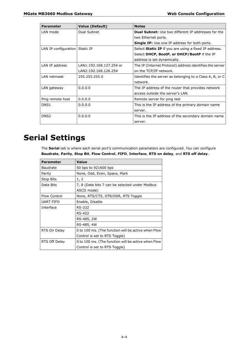
Parameter Value (Default) Notes LAN mode Dual Subnet Dual Subnet: Use two different IP addresses for the
two Ethernet ports. Single IP: Use one IP address for both ports.
LAN IP configuration Static IP Select Static IP if you are using a fixed IP address. Select DHCP, BootP, or DHCP/BootP if the IP address is set dynamically.
LAN IP address LAN1:192.168.127.254 or LAN2:192.168.126.254
The IP (Internet Protocol) address identifies the server on the TCP/IP network.
LAN netmask 255.255.255.0 Identifies the server as belonging to a Class A, B, or C network.
LAN gateway 0.0.0.0 The IP address of the router that provides network access outside the server’s LAN.
Ping remote host 0.0.0.0 Remote server for ping test
DNS1 0.0.0.0 This is the IP address of the primary domain name server.
DNS2 0.0.0.0 This is the IP address of the secondary domain name server.
Serial Settings The Serial tab is where each serial port’s communication parameters are configured. You can configure Baudrate, Parity, Stop Bit, Flow Control, FIFO, Interface, RTS on delay, and RTS off delay.
Parameter Value Baudrate 50 bps to 921600 bps
Parity None, Odd, Even, Space, Mark
Stop Bits 1, 2
Data Bits 7, 8 (Data bits 7 can be selected under Modbus ASCII mode)
Flow Control None, RTS/CTS, DTR/DSR, RTS Toggle
UART FIFO Enable, Disable
Interface RS-232
RS-422
RS-485, 2W
RS-485, 4W
RTS On Delay 0 to 100 ms. (The function will be active when Flow Control is set to RTS Toggle)
RTS Off Delay 0 to 100 ms. (The function will be active when Flow Control is set to RTS Toggle)

MGate MB3660 Modbus Gateway Web Console Configuration
4-5
RTS Delay The RTS Toggle function in flow control is used for RS-232 mode only. This flow-control mechanism is achieved by toggling the RTS pin in the transmission direction. When activated, data will be sent after the RTS pin is toggled ON for the specified time interval. After data transmission is finished, the RTS pin will toggle OFF for the specified time interval.
Protocol Settings The MGate MB3660 provides two operation modes for Modbus communication: Transparent mode and Agent Mode.
In Transparent mode, the gateway will bypass and translate Modbus commands between Modbus TCP/RTU/ASCII. In Agent mode, the gateway will actively poll the Modbus slave devices and store the data in the gateway’s memory. The Modbus master can retrieve Modbus slave devices’ data via the gateway’s memory.
MGate MB3660 Modbus Gateway Web Console Configuration
4-6
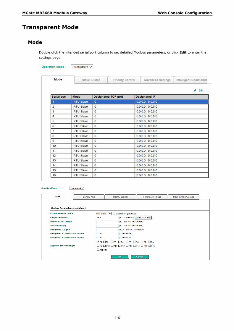
Transparent Mode
Mode
Double click the intended serial port column to set detailed Modbus parameters, or click Edit to enter the settings page.

MGate MB3660 Modbus Gateway Web Console Configuration
4-7
Parameters Description Connected serial device Select the role of the device that is connected to the serial port.
Response timeout According to the Modbus standard, the time it takes for a slave device to respond to a request is defined by the device manufacturer. Based on this response time, a master can be configured to wait a certain amount of time for a slave’s response. If no response is received within the specified time, the master will disregard the request and continue operation. This allows the Modbus system to continue operation even if a slave device is disconnected or faulty.
The MGate MB3660 can also auto-detect the response timeout. Instead of manually figuring out the appropriate setting, you can click Auto Detection to have the MGate figure out the setting for you. Once a value has been recommended, you can fine-tune it to get the best performance.
Inter-character timeout (only for Modbus RTU)
Use this function to determine the timeout interval between characters for Modbus devices that cannot receive Rx signals within an expected time interval. If the response is timed out, all received data will be discarded. The MGate MB3660 will automatically determine the timeout interval if the timeout value is set to 0.
Inter-frame delay (only for Modbus RTU)
The users can determine the time-delay to transmit the data frame received from the slave device to the upstream. The MGate MB3660 will automatically determine the time interval if it is set to 0.
Designated TCP port In RTU/ASCII slave mode, a Modbus command from a specified TCP port can be routed to a specified serial port.
Designated IP 1/2 address for Modbus
In RTU/ASCII slave mode, a Modbus command sent to a specified IP address can be routed to a specified serial port. If the command will come from LAN1 and LAN2 respectively, set different IP addresses accordingly.
For convenience, you can apply the setting to other serial ports by checking the desired ports or to all ports by selecting the All ports checkbox. This feature can dramatically reduce the time needed to configure Modbus gateways that service a large number of serial ports.
Slave ID Map
The Slave ID Map tab is where slave IDs are managed. The definitions on this tab determine how requests will be routed by the unit. With the slave ID table, a routing mechanism is achieved for gateways with two or more serial ports. Since the Modbus devices (all with different slave IDs) are connected to the different serial ports of a gateway, the Modbus requests should be routed to the specific serial port that is connected to the targeted Modbus slave device.
This keeps communication efficient and prevents devices on other ports to receive an unrelated Modbus request, resulting in slowing down the whole system. The slave ID table is used to handle the routing mechanism.
Traditionally, there is a factory default routing. For example, the Modbus requests with slave ID 001~005 will be routed to serial port1, and the Modbus requests with slave ID 006~010 will be routed to serial port2. Users have to set their own customized routing. Select the one you want to set, and click Add / Edit / Delete buttons to change the existing routing. Set each port one by one.

MGate MB3660 Modbus Gateway Web Console Configuration
4-8
Auto Device Routing (patent pending)
The Moxa Modbus gateways provide an auto routing mechanism that eliminates the burdensome task of setting the slave ID table manually. Now, users no longer need to set the routing table. The Moxa Modbus gateways will help detect and route correctly.
Enable Auto Device Routing, and a message window will pop up.

MGate MB3660 Modbus Gateway Web Console Configuration
4-9
Click OK to delete the existing (factory default or user-set) routing table; the auto routing mechanism will automatically find the correct serial port that connects to the target Modbus device. Moreover, if a device is added to the gateway later, the gateway can also route it correctly. Note that the routing table will be clear as illustrated below.
Once the Modbus Master starts to send Modbus requests, the gateway will auto-detect the routing and show results in the web console.
This snapshot shows the routing mechanism is in Auto mode, and the gateway detects that slave ID 1 and 2 are connected to port 1 and slave ID 3 is connected to port2.
If a conflict exists, the table will show the error in red.
For example, two Modbus devices with the same slave ID are connected to serial port 1 and port 2.
MGate MB3660 Modbus Gateway Web Console Configuration
4-10
On the other hand, if you have manually set routing table already and would like to enable the auto routing mechanism for the newly added devices, click No to keep the existing routing table. The gateway will keep the existing user-set routing table and automatically route the newly devices. Note that if a newly added device cannot be polled by the Modbus master correctly; the slave ID of this newly added device might be set in the existing user-set table. Users have to modify the existing user-set table.
How to connect legacy Modbus devices with same slave ID
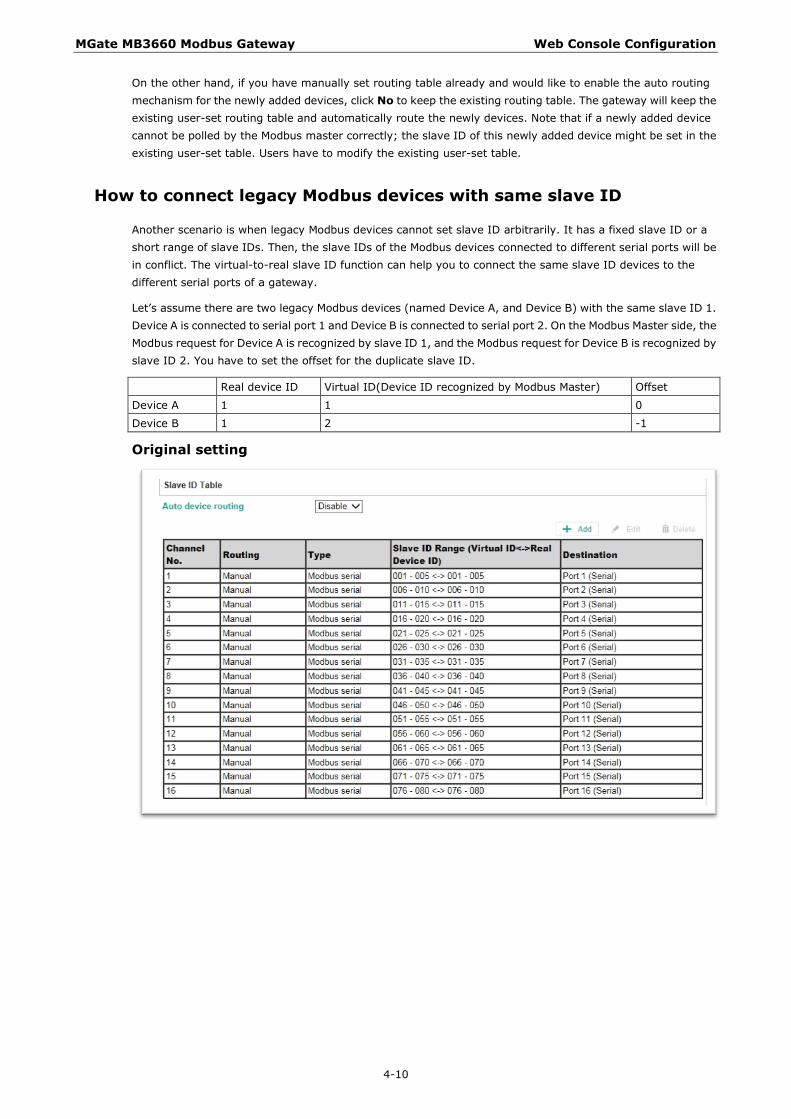
Another scenario is when legacy Modbus devices cannot set slave ID arbitrarily. It has a fixed slave ID or a short range of slave IDs. Then, the slave IDs of the Modbus devices connected to different serial ports will be in conflict. The virtual-to-real slave ID function can help you to connect the same slave ID devices to the different serial ports of a gateway.
Let’s assume there are two legacy Modbus devices (named Device A, and Device B) with the same slave ID 1. Device A is connected to serial port 1 and Device B is connected to serial port 2. On the Modbus Master side, the Modbus request for Device A is recognized by slave ID 1, and the Modbus request for Device B is recognized by slave ID 2. You have to set the offset for the duplicate slave ID.
Real device ID Virtual ID(Device ID recognized by Modbus Master) Offset
Device A 1 1 0
Device B 1 2 -1
Original setting

MGate MB3660 Modbus Gateway Web Console Configuration
4-11
Select the first channel and click Edit. The Slave ID here represents the Virtual ID recognized by the Modbus master.
The routing table will be as follows:
Then, select the second channel and click Edit. Since the virtual ID recognized by the Modbus master side is 2, and the real slave ID of the device B is ID 1, the offset should be set as -1.
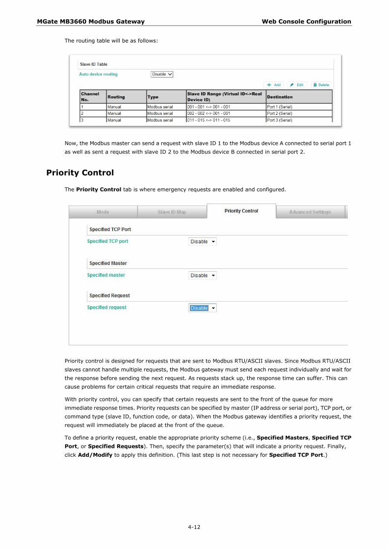
MGate MB3660 Modbus Gateway Web Console Configuration
4-12
The routing table will be as follows:
Now, the Modbus master can send a request with slave ID 1 to the Modbus device A connected to serial port 1 as well as sent a request with slave ID 2 to the Modbus device B connected in serial port 2.
Priority Control
The Priority Control tab is where emergency requests are enabled and configured.
Priority control is designed for requests that are sent to Modbus RTU/ASCII slaves. Since Modbus RTU/ASCII slaves cannot handle multiple requests, the Modbus gateway must send each request individually and wait for the response before sending the next request. As requests stack up, the response time can suffer. This can cause problems for certain critical requests that require an immediate response.
With priority control, you can specify that certain requests are sent to the front of the queue for more immediate response times. Priority requests can be specified by master (IP address or serial port), TCP port, or command type (slave ID, function code, or data). When the Modbus gateway identifies a priority request, the request will immediately be placed at the front of the queue.
To define a priority request, enable the appropriate priority scheme (i.e., Specified Masters, Specified TCP Port, or Specified Requests). Then, specify the parameter(s) that will indicate a priority request. Finally, click Add/Modify to apply this definition. (This last step is not necessary for Specified TCP Port.)

MGate MB3660 Modbus Gateway Web Console Configuration
4-13
Advanced Settings
The Advanced Modbus tab is where certain adjustments can be made to fine tune the communication between different Modbus networks. You can configure Initial Delay, Modbus TCP Exception, Modbus TCP listen port, and Modbus TCP Response Time-out.
Parameter Value Initial delay 0-30000 ms
Modbus TCP exception Enable or Disable
Modbus TCP listen port 1-65535
Modbus TCP response timeout 10-120000 ms
Initial Delay
Some Modbus slaves may take more time to boot up than other devices. For certain environments, this may cause the entire system to suffer from repeated exceptions during the initial boot-up. You can force the MGate to wait after booting up before sending the first request with the Initial Delay setting.
Modbus TCP Exception
The MGate MB3660 is a protocol gateway that transparently passes requests and responses between the Ethernet and serial interfaces. In some situations, it may be necessary for the gateway to return an exception in response to a request from a Modbus TCP master. This is enabled or disabled with the Modbus TCP Exception setting. When enabled, the unit can return two types of exception:
Exception Conditions
Timeout There is no response from the slave. Maybe the device is offline or the serial cable is broken.
Request dropped There are two situations that will result in this exception: The request queue is full (32 request queue for each master) The destination ID is not included in the slave ID map.
Not all Modbus TCP masters require this exception, so it is up to you to determine if this setting should be enabled.
MGate MB3660 Modbus Gateway Web Console Configuration
4-14
Modbus TCP Listen Port
Allow you to change Modbus TCP listen port from the default value (502).
Modbus TCP Response Timeout
According to the Modbus standard, the time that it takes for a slave device to respond to a request is defined by the device manufacturer (refer to Appendix A for details). Based on this response time, a master can be configured to wait a certain amount of time for a slave’s response. If no response is received within the specified time, the master will disregard the request and continue operation. This allows the Modbus system to continue operation even if a slave device is disconnected or faulty.
On the MGate MB3660, the Modbus TCP response timeout field is used to configure how long the gateway will wait for a response from a Modbus ASCII or RTU slave. Refer to your device manufacturer’s documentation to manually set the response timeout.
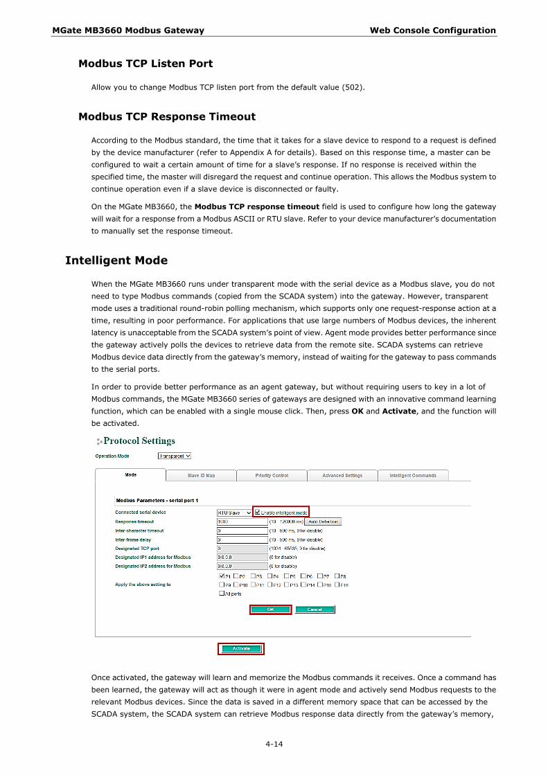
Intelligent Mode
When the MGate MB3660 runs under transparent mode with the serial device as a Modbus slave, you do not need to type Modbus commands (copied from the SCADA system) into the gateway. However, transparent mode uses a traditional round-robin polling mechanism, which supports only one request-response action at a time, resulting in poor performance. For applications that use large numbers of Modbus devices, the inherent latency is unacceptable from the SCADA system’s point of view. Agent mode provides better performance since the gateway actively polls the devices to retrieve data from the remote site. SCADA systems can retrieve Modbus device data directly from the gateway’s memory, instead of waiting for the gateway to pass commands to the serial ports.
In order to provide better performance as an agent gateway, but without requiring users to key in a lot of Modbus commands, the MGate MB3660 series of gateways are designed with an innovative command learning function, which can be enabled with a single mouse click. Then, press OK and Activate, and the function will be activated.
Once activated, the gateway will learn and memorize the Modbus commands it receives. Once a command has been learned, the gateway will act as though it were in agent mode and actively send Modbus requests to the relevant Modbus devices. Since the data is saved in a different memory space that can be accessed by the SCADA system, the SCADA system can retrieve Modbus response data directly from the gateway’s memory,

MGate MB3660 Modbus Gateway Web Console Configuration
4-15
instead of waiting for the data to pass through the Modbus devices, dramatically increasing communication performance.
The learned Modbus commands will be shown on the Intelligent Commands tab. The gateway will act as in agent mode when intelligent mode is activated. Once the Modbus command is learned, the gateway will start to actively poll the Modbus device according to the command learned from the SCADA system. You can edit the learned Modbus commands received from the Modbus master by clicking the Edit button. Since the gateway is actively polling the devices, if you would like to edit commands manually, you first need to deactivate active polling.
The status of intelligent mode will change to Suspended.

MGate MB3660 Modbus Gateway Web Console Configuration
4-16
Click Edit to open the edit page, or click the delete button to delete the command. You may also disable the Modbus command, and then reactivate it when needed.
The gateway now acts as though it were in agent mode and actively polls the Modbus slave devices. The Modbus Master will retrieve the Modbus device’s data directly from the gateway’s memory. If the serial device fails, the Modbus master will not be aware of the failure since it is still getting the Modbus slave’s data from the gateway’s memory. The gateway is designed with a fail report mechanism to inform the Modbus Master. You may set a pre-defined value for the serial port abnormality warning in the Value to TCP master when serial fail text box. When the serial device fails, the gateway will automatically write this predefined value to memory. The Modbus master will be aware of the serial device failure when it receives this predefined value.
Agent mode When running in agent mode, two Modbus roles must be set. One is the Ethernet side (Modbus TCP), and the other is the serial side (Modbus RTU/ASCII).
Modbus TCP Settings
The MGate MB3660 supports a Modbus TCP function with Master (Client) and Slave (Server) modes. For slave mode, the MGate works as a server and waits for incoming connections from the Modbus TCP client. In master mode, the MGate works as a client and tries to build a TCP connection with the remote Modbus TCP slave device.
NOTE Under Modbus TCP server mode, the recommended polling interval of each Modbus request is 2000 ms when establishing 256 Modbus TCP connections. For a requirement that needs a shorter polling interval than 2000 ms, the number of connections should be adjusted accordingly.

MGate MB3660 Modbus Gateway Web Console Configuration
4-17
Slave Mode Settings
The MGate MB3660 supports Modbus slave mode, which means the MGate will work as a server and wait for incoming connection requests. The default TCP listen port is 502. In this mode, the MGate will wait for incoming Modbus TCP requests and use the internal memory as the slave register to respond.
Modify the Slave ID settings to match the system requirements. The default TCP port for Modbus TCP is 502, so you may need to modify if there is a firewall in place.
Parameters Value Description Slave ID 1-255 The Modbus address of the MGate.
TCP port 1-65535 The local TCP port for the MGate.
Master Mode Settings
The MGate MB3660 supports Modbus TCP master mode, which means the MGate will work as a client and send the Modbus command request to the slave device actively. You will need to configure each Modbus command manually. On this page, users can see all the commands listed in the table.

MGate MB3660 Modbus Gateway Web Console Configuration
4-18
Parameters Value Description Initial delay 0-30000 ms Some Modbus slaves may take more time to boot up than
other devices. In some environments, this may cause the entire system to suffer from repeated exceptions during the initial boot-up. You can force the MGate to wait after booting up before sending the first request with the Initial Delay setting.
Max. retry 0-5 This is used to configure how many times the MGate will try to communicate with the Modbus slave.
Response timeout 10-12000 ms This is used to configure how long the MGate will wait for a response from a Modbus slave.
To add a new command or modify the existing one, click the Add button or Modify button and a new dialog box will appear. To remove Modbus commands, select the specific command and then click the Remove button.
To communicate with remote Modbus TCP slave devices, specify the Modbus command for each device. For each Modbus read/write command, specify the internal memory address for data exchange. For the read command, the information received from remote devices will be updated to the specified internal memory address. For the write command, the data in the specified internal memory address will be sent to the remote device. The data will be used to update the remote device register.
Each remote device may need more than one command for communication, so you will need to input all the commands manually.
MGate MB3660 Modbus Gateway Web Console Configuration
4-19
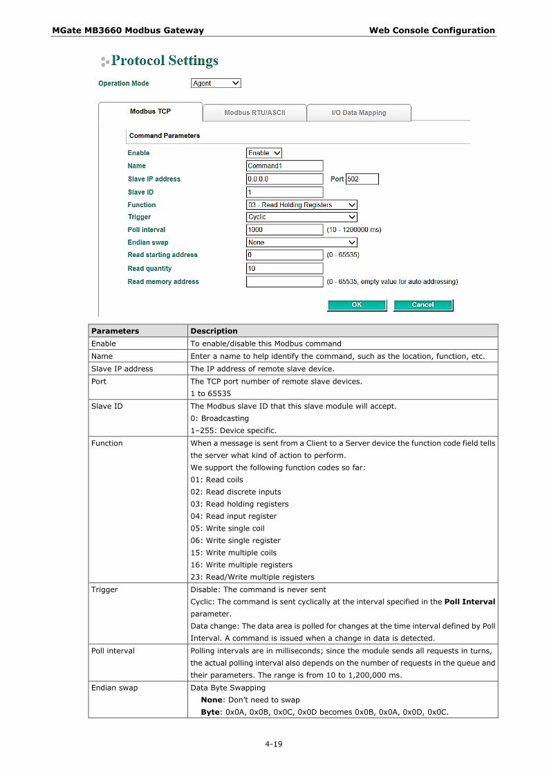
Parameters Description Enable To enable/disable this Modbus command
Name Enter a name to help identify the command, such as the location, function, etc.
Slave IP address The IP address of remote slave device.
Port The TCP port number of remote slave devices. 1 to 65535
Slave ID The Modbus slave ID that this slave module will accept. 0: Broadcasting 1–255: Device specific.
Function When a message is sent from a Client to a Server device the function code field tells the server what kind of action to perform. We support the following function codes so far: 01: Read coils 02: Read discrete inputs 03: Read holding registers 04: Read input register 05: Write single coil 06: Write single register 15: Write multiple coils 16: Write multiple registers 23: Read/Write multiple registers
Trigger Disable: The command is never sent Cyclic: The command is sent cyclically at the interval specified in the Poll Interval parameter. Data change: The data area is polled for changes at the time interval defined by Poll Interval. A command is issued when a change in data is detected.
Poll interval Polling intervals are in milliseconds; since the module sends all requests in turns, the actual polling interval also depends on the number of requests in the queue and their parameters. The range is from 10 to 1,200,000 ms.
Endian swap Data Byte Swapping None: Don’t need to swap Byte: 0x0A, 0x0B, 0x0C, 0x0D becomes 0x0B, 0x0A, 0x0D, 0x0C.

MGate MB3660 Modbus Gateway Web Console Configuration
4-20
Parameters Description Word: 0x0A, 0x0B, 0x0C, 0x0D becomes 0x0C, 0x0D, 0x0A, 0x0B. ByteWord: 0x0A, 0x0B, 0x0C, 0x0D becomes 0x0D, 0x0C, 0x0B, 0x0A.
Read starting address Station Address. The range is from 0 to 65535
Read quantity Specifying how many quantities to write. There are two kinds of quantity units, bit and 16bits, which are associated with function field. The range is from 1 to 125.
Write starting address Station Address. The range is from 0 to 65535
Write quantity Specifying how many quantities to write. There are two kinds of quantity units, bit and 16bits, which are associated with function field. The range is from 1 to 123.
Read/Write memory address
Manually decide the read or write starting address in the gateway’s memory. The range is from 0 to 65535. Set this value as empty for auto addressing by the system.
Opposite side’s command fault
For Modbus TCP master mode, the opposite side refers to the serial port side. The Modbus writer command is sent from the serial port to the TCP side. Once the serial connection fails, the gateway will not be able to receive the serial Master’s write command, but the gateway will continuously send Modbus write commands to the Modbus TCP slave device. To avoid problems when the serial side fails, the MB3660 can be configured to react in one of three ways: keep latest data, clear data to zero, and user-defined value.
Timeout for opposite side’s data update
Defines the timeout for the serial side. The range is from 0 to 65535 ms.
Fault Protection and Status Monitoring
Fault Protection The Fault Protection function sends a predefined setting to field devices to prevent incorrect actions when the upstream connection is lost.
The MB3660 supports a Fault Protection function when in agent mode. You can configure the criteria used to determine what to do when the write command is no longer received from the master side. For example, when a cable comes loose accidentally, the most up-to-date write command from the master side will not be received by the gateway. Hence, the slave device will use the latest command from the gateway, which is now out-of-date, creating an inconsistency between the master and slave devices. To avoid this problem, the MB3660 supports options to determine which actions should be taken when the master’s side is disconnected from the gateway.
Options Description Keep latest data The gateway will write the same data to the slave device.
Clear data to zero The gateway will write zero values to the slave device.
User-define value A user-defined value will be written to the slave device.

MGate MB3660 Modbus Gateway Web Console Configuration
4-21
Use the Timeout for serial side’s data update item to set how long the gateway will wait to activate this function.
Status Monitoring The Status Monitoring function provides status information of field devices when the MGate is being used as a master/client; information includes alive list, counter, the result of commands issued, etc.
For Modbus gateways in agent mode, if a slave device fails or a cable comes loose, generally the gateway won’t be able to receive up-to-date data from the slave device. The out-of-date data will be stored in gateway’s memory and will be retrieved by the Modbus master, which will not be aware that the slave device is not providing up-to-date data. The MB3660 supports the Status Monitoring function, which provides a warning mechanism to report the list of slave devices that are still “alive.”
In agent mode, each serial port supports 32 Modbus commands. Hence, there are at most 512 Modbus commands for all serial devices. The MB3660 allocates 1 bit of the gateway’s specified memory address to indicate the status of each Modbus command as being normal or abnormal. In other words, the MB3660 allocates 512 bits of memory to indicate the status of all Modbus commands. If a command has run successfully, the status value will continuously be 0. On the contrary, if a command has failed, the status will be set to 1. In this case, the Modbus TCP master will be aware of the failure status of the slave device in relation to the Modbus command.
In agent mode, when the Modbus TCP master queries Modbus serial slave devices, the MB3660 plays the role of TCP slave on the Ethernet side, and consequently is assigned a Modbus TCP slave ID. The Modbus TCP master can retrieve the Modbus slave devices’ status via Modbus command with the following information.
MGate MB3660 Modbus Gateway Web Console Configuration
4-22
Slave ID [MB3660’s Modbus TCP slave ID]
Function 0x03 or 0x04
Address 40001~
Quantity 32 words for MB3660-16, 16 words for MB3660-8
When a Modbus serial master queries the Modbus TCP slave devices, the MB3660 plays the role of serial slave on the serial side, and consequently is assigned a Modbus serial slave ID. The Modbus serial master can retrieve the Modbus TCP slave devices’ status via Modbus command with the following information.
Slave ID [MB3660’s Modbus RTU/ASCII slave ID]
Function 0x03 or 0x04
Address 41001~
Quantity 16 words
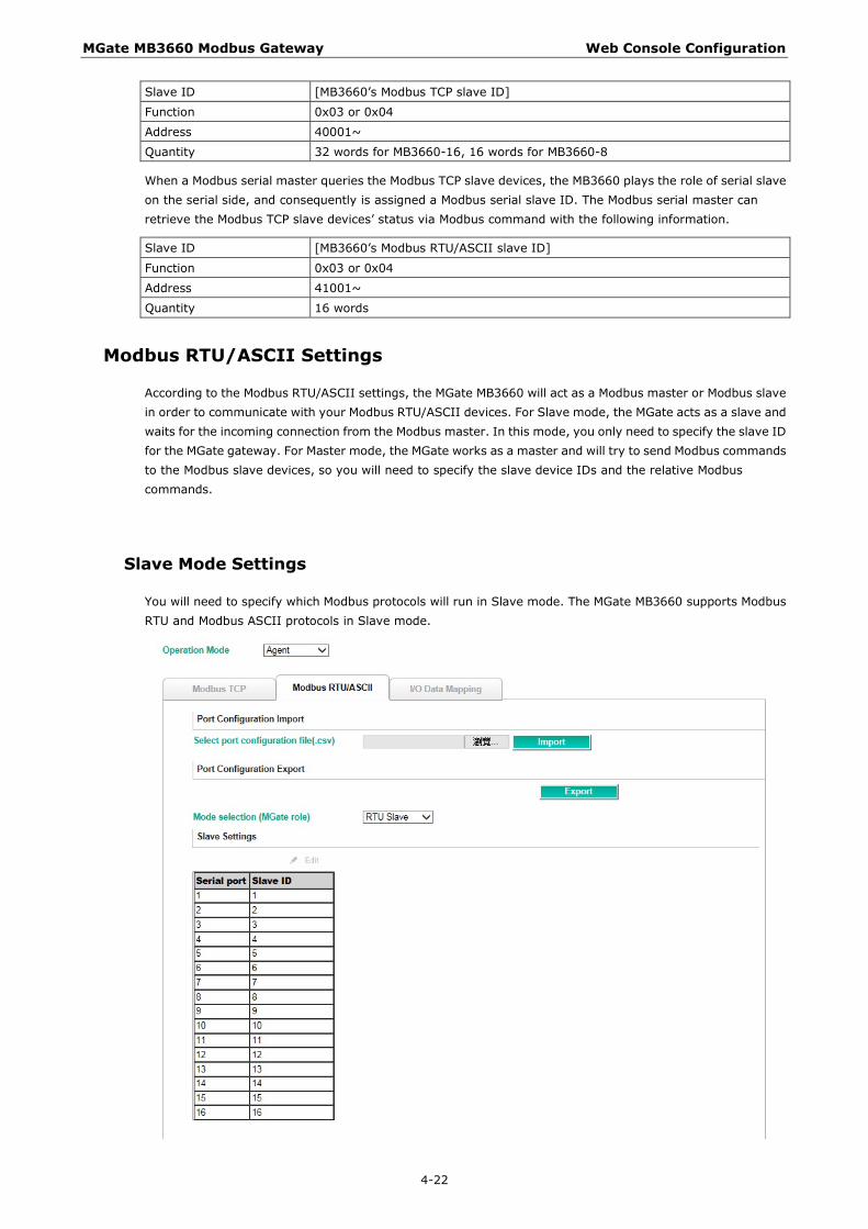
Modbus RTU/ASCII Settings
According to the Modbus RTU/ASCII settings, the MGate MB3660 will act as a Modbus master or Modbus slave in order to communicate with your Modbus RTU/ASCII devices. For Slave mode, the MGate acts as a slave and waits for the incoming connection from the Modbus master. In this mode, you only need to specify the slave ID for the MGate gateway. For Master mode, the MGate works as a master and will try to send Modbus commands to the Modbus slave devices, so you will need to specify the slave device IDs and the relative Modbus commands.
Slave Mode Settings
You will need to specify which Modbus protocols will run in Slave mode. The MGate MB3660 supports Modbus RTU and Modbus ASCII protocols in Slave mode.

MGate MB3660 Modbus Gateway Web Console Configuration
4-23
Double click a serial port for additional settings, or click the intended serial port and then click Edit.
Parameters Value Description Slave ID 1-255 The Modbus Slave ID that this slave module will accept.
1–255: Device specific.
You can change the Modbus slave ID on this page. If two or more serial ports use the same slave ID, you can check to see if they use the same setting. If two or more slave devices are using the same slave ID connected to different serial ports, you can click the intended serial ports for the same slave ID setting.
Master Mode Settings
You will need to specify which Modbus protocols will run in Master mode. The MGate MB3660 supports Modbus RTU and Modbus ASCII protocols in Master mode.

MGate MB3660 Modbus Gateway Web Console Configuration
4-24
The MGate MB3660 also provides several advanced settings for specific application requirements. The following settings are optional for most applications. It is suggested to use the default settings to test the MGate MB3660.
Double click the intended serial port to configure additional settings.
Parameters Description Initial delay Some Modbus slaves may take more time to boot up than other devices. In some
environments, this may cause the entire system to suffer from repeated exceptions during the initial boot-up. You can force the MGate to wait after booting up before sending the first request with the Initial Delay setting.
Max. retry The number of times the master will retry the same request when the response times out.
Response timeout According to the Modbus standard, the time it takes for a slave device to respond to a request is defined by the device manufacturer. Based on this response time, a master can be configured to wait a certain amount of time for a slave’s response. If no response is received within the specified time, the master will disregard the request and continue operation. This allows the Modbus system to continue operation even if a slave device is disconnected or faulty. On the MGate 5101-MB-EIP, the Response timeout field is used to configure how long the gateway will wait for a response from a Modbus ASCII or RTU slave. Refer to your device manufacturer’s documentation to manually set the response time.
Inter-frame delay The users can determine the time-delay to transmit the data frame received from the slave device to the upstream. The MGate MB3660 will automatically determine the time interval if it is set to 0.
Inter-character timeout Use this function to determine the timeout interval between characters for Modbus devices that cannot receive Rx signals within an expected time interval. If the response is timed out, all received data will be discarded. The MGate MB3660 will automatically determine the timeout interval if the timeout value is set to 0.
For Master mode, you must identify which Modbus requests need to be sent to Modbus slave devices through serial interface. The data will be exchanged between slave devices and the MGate gateway’s internal memory. To do this, manually add all Modbus commands that will handle the data exchange.

MGate MB3660 Modbus Gateway Web Console Configuration
4-25
The Add, Edit, Copy, and Delete buttons support the Modbus command arrangement. When you click on the Add and Edit buttons, the following dialog box will be displayed.
The description of all the fields can refer to Agent mode---Master Mode Settings.
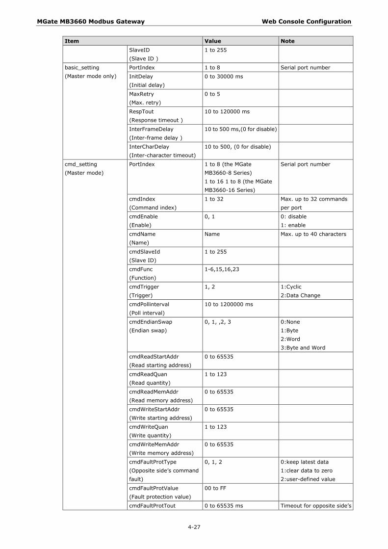
Port Configuration
A Modus RTU/ASCII master may set several commands that are sent to slave devices. Some users are familiar with CSV file format to edit these commands. Therefore, MGate MB3660 supports the import or export functions for CSV files.

MGate MB3660 Modbus Gateway Web Console Configuration
4-26
First, click Export to generate the template file.
Then open the exported CSV file to further configure.
Make sure to follow the format or an error will occur when the file is imported. The detail description of the format is shown below.
Port Configuration Format Item Value Note mode_type 0, 1, 2, 3 0: RTU Slave
1: RTU Master 2: ASCII Slave 3: ASCII Master
basic_setting (RTU/ASCII Slave mode only)
PortIndex 1 to 8 (the MGate MB3660-8 Series) 1 to 16 1 to 8 (the MGate MB3660-16 Series)
Serial port number
MGate MB3660 Modbus Gateway Web Console Configuration
4-27
Item Value Note SlaveID (Slave ID )
1 to 255
basic_setting (Master mode only)
PortIndex 1 to 8 Serial port number
InitDelay (Initial delay)
0 to 30000 ms
MaxRetry (Max. retry)
0 to 5
RespTout (Response timeout )
10 to 120000 ms
InterFrameDelay (Inter-frame delay )
10 to 500 ms,(0 for disable)
InterCharDelay (Inter-character timeout)
10 to 500, (0 for disable)
cmd_setting (Master mode)
PortIndex 1 to 8 (the MGate MB3660-8 Series) 1 to 16 1 to 8 (the MGate MB3660-16 Series)
Serial port number
cmdIndex (Command index)
1 to 32 Max. up to 32 commands per port
cmdEnable (Enable)
0, 1 0: disable 1: enable
cmdName (Name)
Name Max. up to 40 characters
cmdSlaveId (Slave ID)
1 to 255
cmdFunc (Function)
1-6,15,16,23
cmdTrigger (Trigger)
1, 2 1:Cyclic 2:Data Change
cmdPollinterval (Poll interval)
10 to 1200000 ms
cmdEndianSwap (Endian swap)
0, 1, ,2, 3 0:None 1:Byte 2:Word 3:Byte and Word
cmdReadStartAddr (Read starting address)
0 to 65535
cmdReadQuan (Read quantity)
1 to 123
cmdReadMemAddr (Read memory address)
0 to 65535
cmdWriteStartAddr (Write starting address)
0 to 65535
cmdWriteQuan (Write quantity)
1 to 123
cmdWriteMemAddr (Write memory address)
0 to 65535
cmdFaultProtType (Opposite side’s command fault)
0, 1, 2 0:keep latest data 1:clear data to zero 2:user-defined value
cmdFaultProtValue (Fault protection value)
00 to FF
cmdFaultProtTout 0 to 65535 ms Timeout for opposite side’s

MGate MB3660 Modbus Gateway Web Console Configuration
4-28
Item Value Note (Timeout for opposite side’s data update)
data update
NOTE In [basic_setting], the value of “portIndex” must be bigger than the previous row.
In [cmd_setting], the value of “portIndex” must be equal or bigger than the previous row.
In [cmd_setting], the value of “cmdIndex” must be bigger than the previous row.
Content that appears after the “#” character will be ignored. It is used to write notes on the CSV file.
Error Message If you import an invalid format of a configuration file, a notification message will pop up to show which columns and rows are incorrect on the web console. Two types of errors should be avoided.
Format Error invalid character, absent/additional columns/rows below data block.
Data Range Error value is out of range.(Ref Port Configuration Format)
I/O Data Mapping
You can verify the gateway’s memory allocation on the I/O Data Mapping page. First select the Modbus data flow you want to see.
In agent mode, you need to manually set Modbus commands one-by-one and assign a gateway memory address for storing this data. We recommend using I/O Data Mapping to check the memory address of each command.

MGate MB3660 Modbus Gateway Web Console Configuration
4-29
Example 1 If there are two commands with the same internal address as shown in the figure below.
You can click on the Re-Arrange button to automatically address the internal address. The update internal address will become as follows:

MGate MB3660 Modbus Gateway Web Console Configuration
4-30
Example 2 On the contrary, you can also set the internal address manually. For example, if you add two Modbus commands that Command3 uses addresses 0 to 1, whereas Command4 uses addresses 2 to 3, then obviously a memory overlap exists.
To rectify the error, click Command4 to change its starting address from 2 to 3.
Once the change has been made, each of the two commands will be allocated to unique address ranges in the gateway’s memory. That is, the address for command 3 will be in the range 0 to 1, whereas command 4 will be in the range 2 to 3.
MGate MB3660 Modbus Gateway Web Console Configuration
4-31
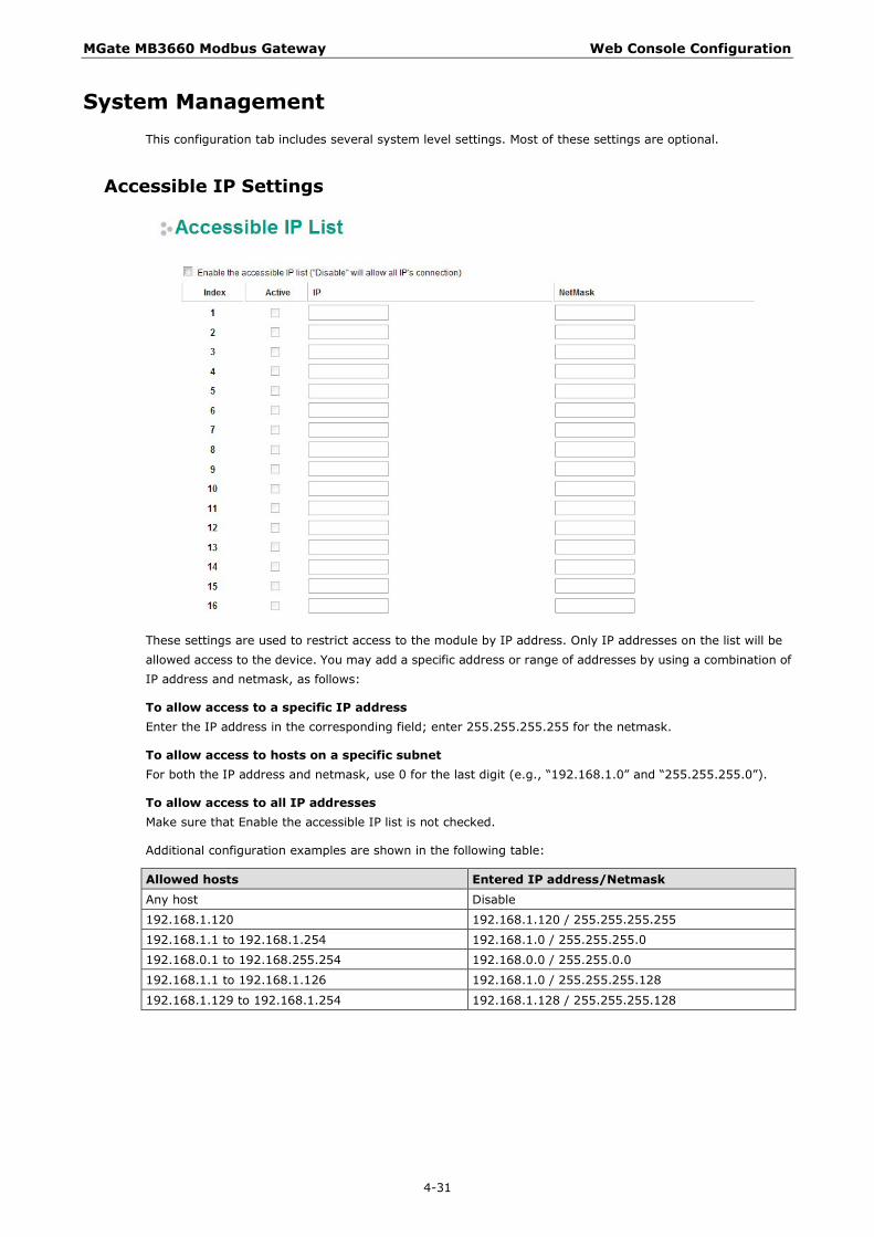
System Management This configuration tab includes several system level settings. Most of these settings are optional.
Accessible IP Settings
These settings are used to restrict access to the module by IP address. Only IP addresses on the list will be allowed access to the device. You may add a specific address or range of addresses by using a combination of IP address and netmask, as follows:
To allow access to a specific IP address Enter the IP address in the corresponding field; enter 255.255.255.255 for the netmask.
To allow access to hosts on a specific subnet For both the IP address and netmask, use 0 for the last digit (e.g., “192.168.1.0” and “255.255.255.0”).
To allow access to all IP addresses Make sure that Enable the accessible IP list is not checked.
Additional configuration examples are shown in the following table:
Allowed hosts Entered IP address/Netmask Any host Disable
192.168.1.120 192.168.1.120 / 255.255.255.255
192.168.1.1 to 192.168.1.254 192.168.1.0 / 255.255.255.0
192.168.0.1 to 192.168.255.254 192.168.0.0 / 255.255.0.0
192.168.1.1 to 192.168.1.126 192.168.1.0 / 255.255.255.128
192.168.1.129 to 192.168.1.254 192.168.1.128 / 255.255.255.128
MGate MB3660 Modbus Gateway Web Console Configuration
4-32
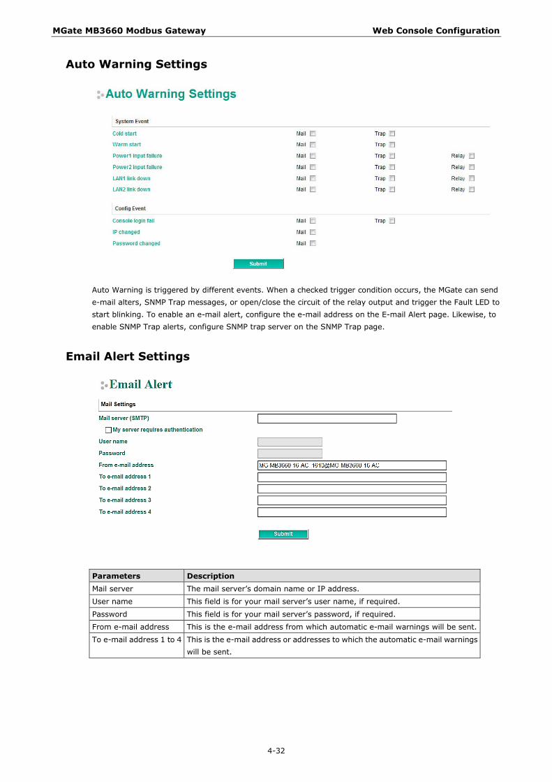
Auto Warning Settings
Auto Warning is triggered by different events. When a checked trigger condition occurs, the MGate can send e-mail alters, SNMP Trap messages, or open/close the circuit of the relay output and trigger the Fault LED to start blinking. To enable an e-mail alert, configure the e-mail address on the E-mail Alert page. Likewise, to enable SNMP Trap alerts, configure SNMP trap server on the SNMP Trap page.
Email Alert Settings
Parameters Description Mail server The mail server’s domain name or IP address.
User name This field is for your mail server’s user name, if required.
Password This field is for your mail server’s password, if required.
From e-mail address This is the e-mail address from which automatic e-mail warnings will be sent.
To e-mail address 1 to 4 This is the e-mail address or addresses to which the automatic e-mail warnings will be sent.

MGate MB3660 Modbus Gateway Web Console Configuration
4-33
SNMP Trap Settings
Parameters Description SNMP trap server IP Use this field to indicate the IP address to use for receiving SNMP traps.
Trap community Use this field to designate the SNMP trap community.
SNMP Agent Settings
Parameters Description SNMP To enable the SNMP Agent function, select the Enable option, and enter a
community name (e.g., public).
Read community string This is a text password mechanism that is used to weakly authenticate queries to agents of managed network devices.
Contact name The optional SNMP contact information usually includes an emergency contact name and telephone or pager number.
Location For storing the SNMP’s location information.
Misc. Settings
This page includes console settings, password, RADIUS Server, and User Table.

MGate MB3660 Modbus Gateway Web Console Configuration
4-34
Console Settings
Parameters Value Description HTTP Enable/Disable This setting is to enable/disable the web console.
Telnet console Enable/Disable This setting is to enable/disable the telnet console.
Reset button Disable after 60 sec, Always enable
The MGate provides a reset button to clear the password or load factory default settings. For security reasons, you can disable this function. In disabled mode, the MGate will still enable this function within 60 seconds after power-up; 60 seconds later, the function will be disabled.
Console authentication type
Local/RADIUS/RADIUS-Local, Local-RADIUS
Determines the RADIUS authentication type.
Try next type on authentication denied
Disable/Enable When the above multitype authentication fails, enable/disable to try next type of authentication automatically.
Auto logout time 60-3600 sec Set the auto logout time period.
Change Admin Password
You can modify the password for the account admin. The default password is moxa. To change the password, type the existing password and then type the new password twice. Click Submit to activate the new password.
RADIUS Server
Parameters Description RADIUS Server The name of the RADIUS server.
RADIUS key The key for RADIUS authentication (be sure to type in the correct key)
UDP port Support UDP port: 1645 (default )/1812.

MGate MB3660 Modbus Gateway Web Console Configuration
4-35
User Table
The administrator can create a list of user names with passwords for logging in to the MGate MB3660.
Maintenance
Other gateway maintenance settings.
Ping
To test the network status with the PING function, enter the PING server IP address, click Start, and wait for a response.
Firmware Upgrade
Firmware updates for the MGate MB3660 are located at www.moxa.com. After you have downloaded the new firmware onto your PC, you can use DSU to write it onto your MGate MB3660. Select the desired unit from the list and click to begin the process. Choose the correct file and click Submit to upgrade the firmware.
ATTENTION
DO NOT turn off the MGate power before the firmware upgrade progress completes. The MGate will be erasing the old firmware to make room for the new firmware to flash memory. If you power off the MGate and terminate the progress, the flash memory will contain corrupted firmware and the MGate will fail to boot. If this happens, call Moxa RMA services.

MGate MB3660 Modbus Gateway Web Console Configuration
4-36
Configuration Import/Export
There are three main reasons for using the Import and Export functions.
• Applying the same configuration to multiple units The Import/Export configuration function is a convenient way to apply the same settings to units located in different sites. You can export the configuration as a file and then import the configuration file onto other units at any time.
• Backing up configurations for system recovery The export function allows you to export configuration files that can be imported onto other gateways to restore malfunctioning systems within minutes.
• Troubleshooting Exported configuration files can help administrators to identify system problems provide useful information for Moxa’s Technical Service Team when maintenance visits are requested.
The import or export function saves all the configuration settings and parameters of the MGate MB3660 in a *.ini file. To begin, click the Import or Export button.
Once the file has been saved, it can be imported into your target unit to duplicate the same settings. Select the target unit first and then click the Import button to complete the import action.
Load Factory Default
To clear all the settings on the unit, use the Load Default button to reset the unit to its initial factory default values.
Click Submit to restore the unit to factory default values.
ATTENTION
Load Default will completely reset the configuration of the unit, and all of the parameters you have saved will be discarded. Do not use this function unless you are sure you want to completely reset your unit.

MGate MB3660 Modbus Gateway Web Console Configuration
4-37
System Monitoring The MGate MB3660 provides two system monitoring functions: Relay status and Protocol status.
Relay Status
The MGate MB3660 has a built-in 3-pin relay output. It can be triggered by power input failure and LAN link down. Enable the relay output functions by clicking the relay check box in the Auto Warning Settings.
When a warning event occurs, the relay circuit will activate to enable the warning device, such as a beeper. The field engineer can click the Acknowledge Event button to temporarily deactivate the relay circuit and then take some time to troubleshoot the problem.
Once the abnormality has been resolved, the relay will return to normal status.
Protocol Status
The MGate MB3660 has a built-in Modbus diagnosis/traffic monitor function. For troubleshooting or management purposes, you can diagnose the Modbus protocol communication status and monitor Modbus RTU/ASCII/TCP data passing through the MGate MB3660.
For transparent mode, it presents the data in an intelligent, easy-to-understand format with clearly designated fields, including source, destination, function code, and data. Events can be filtered in different ways, and the complete log can be saved to a file for later analysis.

MGate MB3660 Modbus Gateway Web Console Configuration
4-38
For agent mode, it includes I/O Data View, Modbus RTU/ASCII/TCP Diagnose, and Modbus RTU/ASCII/TCP Traffic. The I/O Data view page displays the internal memory information for input and output data transfers.
For agent mode, it includes Diagnose function, which provides status information for Modbus RTU/ASCII/TCP troubleshooting. Verify the connection status or packet counters to make sure communications are running smoothly.
For agent mode, the traffic monitoring function can capture both Modbus RTU/ASCII and Modbus TCP communication logs, respectively, which present the data in an intelligent, easy-to-understand format with clearly designated fields including source, destination, function code, and data. Events can be filtered in different ways, and the complete log can be saved to a file for later analysis.

MGate MB3660 Modbus Gateway Web Console Configuration
4-39
Save/Restart All changes will be activated by clicking the Submit button first and then restarting the gateway. If a lot of settings need to be changed, you can click Submit for each setting and then click Save/Restart to activate all the changes.
Logout For safety reasons, remember to log out of the web utility to prevent people who do not have the proper authorization from accessing the gateway.
MXView The Moxa MXview network management software gives you a convenient graphical representation of your Ethernet network and allows you to configure, monitor, and diagnose Moxa networking devices. MXview provides an integrated management platform that can manage the Moxa MGate Series of products as well as Ethernet switches and wireless APs, and SNMP-enabled and ICMP-enabled devices installed on subnets. MXview includes an integrated MIB complier that supports any third-party MIB. It also allows you to monitor third-party OIDs and Traps. Network and Trap components that have been located by MXview can be managed via web browsers from both local and remote sites—anytime, anywhere.

MGate MB3660 Modbus Gateway Web Console Configuration
4-40
MXconfig Moxa’s MXconfig is a comprehensive Windows-based utility that is used to install, configure, and maintain multiple Moxa devices in industrial networks. This suite of useful tools helps users set the IP addresses of multiple devices with one click, configure the redundant protocols and VLAN settings, modify multiple network configurations of multiple Moxa devices, upload firmware to multiple devices, export/import configuration files, copy configuration settings across devices, easily link to web and telnet consoles, and test device connectivity. MXconfig gives device installers and control engineers a powerful and easy way to mass configure devices, and effectively reduces the setup and maintenance cost.
For more detailed information regarding MXview, download the MXview user’s manual from Moxa’s website at http://www.moxa.com

5 5. Typical Applications
The following topics are covered in this chapter:
Ethernet Masters with Multiple Serial Slaves
Serial Masters with Multiple Ethernet Slaves
Modbus TCP Masters with ASCII and RTU Slaves
Serial Master with Serial Slaves over Internet

MGate MB3660 Modbus Gateway Typical Applications
5-2
Ethernet Masters with Multiple Serial Slaves
Connect all Modbus devices over an Ethernet network
Most modern PLCs and host computers support Modbus TCP over Ethernet. In order to access discrete Modbus RTU/ASCII devices for data collection and control, they can rely on the MGate MB3660 Modbus gateway.
The MGate MB3660 supports Modbus TCP with up to 256 simultaneous connections. The serial interface supports both RS-232 and RS-422/485, selectable through software. Each serial port can be connected to one RS-232 or RS-422 serial device, or to 31 RS-485 serial devices.
Serial Masters with Multiple Ethernet Slaves
Link a serial master device with Ethernet slave devices
Many HMI (Human Machine Interface) systems use a serial interface to connect to a discrete DCS (Data Control System). However, many DCSs are now Ethernet-based and operate as a Modbus TCP slave device.
The MGate MB3660 Modbus gateway can link a serial-based HMI to distributed DCSs over an Ethernet network. Up to 128 Modbus TCP slave devices are supported by each MGate MB3660.

MGate MB3660 Modbus Gateway Typical Applications
5-3
Modbus TCP Masters with ASCII and RTU Slaves
Link TCP master devices with both ASCII and RTU serial devices
simultaneously
When integrating Modbus networks, you may encounter different Modbus serial networks that use different baudrates or a different protocol. Modbus ASCII might be used by some devices, while Modbus RTU is used by other devices.
The MGate models with two or more ports can integrate serial Modbus networks that use different parameters or protocols. You can configure each serial port to a specific Modbus serial environment to set up a slave ID map. After configuration, only the gateway will be visible to Modbus TCP masters, and all serial devices will be integrated behind it.
Serial Master(s) with Serial Slaves
Let Modbus serial devices communicate
The MGate MB3660 provides a feature for connecting serial master(s) with serial slave devices by using transparent mode. You only need to set up the slave ID routing mechanism.
6 6. Case Studies
The following topics are covered in this chapter:
Introduction
Replace Serial Masters with Ethernet Master(s), Configurable Slave IDs
Replace Serial Masters with Ethernet Master(s), Fixed Slave IDs
Keep Serial Master and Add Ethernet Master(s)
Integrate Modbus RTU, ASCII, and TCP at the Same Time

MGate MB3660 Modbus Gateway Case Studies
6-2
Introduction For many reasons, a Modbus gateway might be used to integrate Modbus networks. However, every situation has its own requirements and difficulties. Users may wonder how the gateway can help or even if the gateway is suitable for the system.
Replace Serial Masters with Ethernet Master(s), Configurable Slave IDs
In this scenario, the original control system consists of several serial-based systems. In each system, a serial master directly controls serial slave devices as follows:
The MGate MB3660 can connect to each serial slave so Ethernet SCADA masters will be able to control them. However, since slave IDs cannot be repeated in a system, we will need to change the IDs of some of the slaves in order to integrate them into a single network, as follows:

MGate MB3660 Modbus Gateway Case Studies
6-3
Replace Serial Masters with Ethernet Master(s), Fixed Slave IDs
Some legacy Modbus slave devices have fixed IDs that cannot be changed. In order to integrate the devices into a Modbus TCP network, a multiport MGate model can be used to assign virtual slave IDs. For more information about virtual slave IDs, refer to Set Up Slave ID Mapping, chapter 4.
Keep Serial Master and Add Ethernet Master(s) In this scenario, the serial control system is a direct, low-latency system. The serial master must not be replaced, but Ethernet masters will need to have access to the serial slaves for monitoring or supervision.

MGate MB3660 Modbus Gateway Case Studies
6-4
Integrate Modbus RTU, ASCII, and TCP at the Same Time
There can be a wide range in number, type, and sophistication of devices on the factory floor. The most common devices are simple serial-based meters, which report certain information relating to factory environment or equipment. However, other Modbus serial slaves may be as complex as a manufacturing machine or a PLC controller.
When integrating these devices, there may be issues if different serial environments are used for different devices. One system may use a different baudrate than another, or may use Modbus ASCII instead of Modbus RTU. The MGate MB3660 allows the different Modbus systems to be integrated into one network, regardless of the protocol or communication parameters.

A A. Modbus Overview
Introduction Modbus is one of the most popular automation protocols in the world. It supports both serial and Ethernet devices. Many industrial devices, such as PLCs, DCSs, HMIs, instruments, meters, motors, and drivers, use Modbus as their communication standard.
Devices are Either Masters or Slaves All Modbus devices are classified as either a master or a slave. Masters initiate all communication with slaves and do not communicate to other masters. Slaves are completely passive and communicate only by sending a response to a master’s request.
Slaves are Identified by ID Each Modbus slave in a system is assigned a unique ID between 1 and 247. Whenever a master makes a request, the request must include the ID of the intended recipient. Master devices themselves have no ID.
0 1~247 248~255
Broadcast address Slave individual address Reserved
Communication is by Request and Response All Modbus communication is by request and response. A master sends a request and a slave sends a response. The master will wait for the slave’s response before sending the next request. For broadcast commands, no response is expected. This is illustrated by three scenarios as follows:
Normal
The master sends a request to the slave. The slave sends a response with the requested information.

MGate MB3660 Modbus Gateway Modbus Overview
A-2
Exception
The master sends a request to the slave. The slave may not support the command or an error is detected, so it sends an exception to the master.
Broadcast
The master sends a broadcast command, such as a reset command. Every slave on the network complies with the command, and no response is sent to the master.
Requests Need a Time Limit The original Modbus protocol was not designed for simultaneous requests or simultaneous masters, so only one request on the network can be handled at a time. When a master sends a request to a slave, no other communication may be initiated until after the slave responds. The Modbus protocol specifies that masters use a response timeout function to identify when a slave is nonresponsive due to device or line failure. This function allows a master to give up on a request if no response is received within a certain amount of time. This is illustrated as follows:
Response Timeout
The master sends a request. The slave is unresponsive for the amount of time specified by the response timeout function. The master gives up on the request and resumes operation, allowing another request to be initiated.
To allow for a wide range of devices, baudrates, and line conditions, actual response timeout values are left open for manufacturers to determine. This allows the Modbus protocol to accommodate a wide range of devices and systems. However, this also makes it difficult for system integrators to know what response timeout value to use during configuration, especially with older or proprietary devices.
The MGate MB3660 provides a patent-pending function that tests all attached devices and recommends a response timeout value. This function saves considerable time and effort for system integrators and results in more accurate timeout settings.
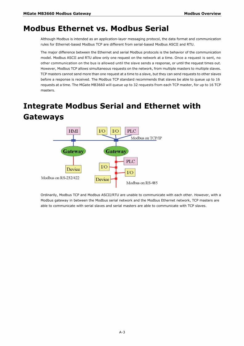
MGate MB3660 Modbus Gateway Modbus Overview
A-3
Modbus Ethernet vs. Modbus Serial Although Modbus is intended as an application-layer messaging protocol, the data format and communication rules for Ethernet-based Modbus TCP are different from serial-based Modbus ASCII and RTU.
The major difference between the Ethernet and serial Modbus protocols is the behavior of the communication model. Modbus ASCII and RTU allow only one request on the network at a time. Once a request is sent, no other communication on the bus is allowed until the slave sends a response, or until the request times out. However, Modbus TCP allows simultaneous requests on the network, from multiple masters to multiple slaves. TCP masters cannot send more than one request at a time to a slave, but they can send requests to other slaves before a response is received. The Modbus TCP standard recommends that slaves be able to queue up to 16 requests at a time. The MGate MB3660 will queue up to 32 requests from each TCP master, for up to 16 TCP masters.
Integrate Modbus Serial and Ethernet with Gateways
Ordinarily, Modbus TCP and Modbus ASCII/RTU are unable to communicate with each other. However, with a Modbus gateway in between the Modbus serial network and the Modbus Ethernet network, TCP masters are able to communicate with serial slaves and serial masters are able to communicate with TCP slaves.