mgate 5101-pbm-mn profibus master-to-modbus tcp gateway ... · mgate 5101-pbm-mn profibus...
TRANSCRIPT

MGate 5101-PBM-MN PROFIBUS Master-to-Modbus TCP Gateway
User’s Manual
Edition 4.1, May 2017
www.moxa.com/product
© 2017 Moxa Inc. All rights reserved.
MGate 5101-PBM-MN PROFIBUS Master-to-Modbus TCP Gateway
User’s Manual
The software described in this manual is furnished under a license agreement and may be used only in accordance with the terms of that agreement.
Copyright Notice
© 2017 Moxa Inc. All rights reserved.
Trademarks
The MOXA logo is a registered trademark of Moxa Inc. All other trademarks or registered marks in this manual belong to their respective manufacturers.
Disclaimer
Information in this document is subject to change without notice and does not represent a commitment on the part of Moxa.
Moxa provides this document as is, without warranty of any kind, either expressed or implied, including, but not limited to, its particular purpose. Moxa reserves the right to make improvements and/or changes to this manual, or to the products and/or the programs described in this manual, at any time.
Information provided in this manual is intended to be accurate and reliable. However, Moxa assumes no responsibility for its use, or for any infringements on the rights of third parties that may result from its use.
This product might include unintentional technical or typographical errors. Changes are periodically made to the information herein to correct such errors, and these changes are incorporated into new editions of the publication.
Technical Support Contact Information
www.moxa.com/support
Moxa Americas Toll-free: 1-888-669-2872 Tel: +1-714-528-6777 Fax: +1-714-528-6778
Moxa China (Shanghai office) Toll-free: 800-820-5036 Tel: +86-21-5258-9955 Fax: +86-21-5258-5505
Moxa Europe Tel: +49-89-3 70 03 99-0 Fax: +49-89-3 70 03 99-99
Moxa Asia-Pacific Tel: +886-2-8919-1230 Fax: +886-2-8919-1231
Moxa India Tel: +91-80-4172-9088 Fax: +91-80-4132-1045

Table of Contents
1. Introduction ...................................................................................................................................... 1-1 Overview ........................................................................................................................................... 1-2 Package Checklist ............................................................................................................................... 1-2 Product Features ................................................................................................................................ 1-2
2. Hardware .......................................................................................................................................... 2-1 Power Input and Relay Output Pinouts................................................................................................... 2-2 LED Indicators .................................................................................................................................... 2-2 Dimensions ........................................................................................................................................ 2-3 Pin Assignments ................................................................................................................................. 2-3
PROFIBUS Pin Assignment ............................................................................................................ 2-3 Console (RS-232) Pin Assignment ................................................................................................. 2-3
Mounting the Unit ............................................................................................................................... 2-4 Specifications ..................................................................................................................................... 2-4 Reset Button ...................................................................................................................................... 2-5
3. Getting Started.................................................................................................................................. 3-1 Connecting the Power ......................................................................................................................... 3-2 Connecting PROFIBUS Devices ............................................................................................................. 3-2 Connecting to a Network ..................................................................................................................... 3-2 Logging in to the Web Console ............................................................................................................. 3-2 Network Settings ................................................................................................................................ 3-3 Data Transfer ..................................................................................................................................... 3-3 PROFIBUS Network ............................................................................................................................. 3-3 Modbus TCP Configuration ................................................................................................................... 3-3 Configuring the MGate ......................................................................................................................... 3-4 MXStudio ........................................................................................................................................... 3-4
4. Configuration (MGate Manager) ........................................................................................................ 4-1 Installing the Software ........................................................................................................................ 4-2 Starting MGate Manager ...................................................................................................................... 4-4 Connecting to the Unit ......................................................................................................................... 4-6 Modifying the Configuration ................................................................................................................. 4-6 Password Protection ............................................................................................................................ 4-7
Configure Device ......................................................................................................................... 4-7 Network Settings ......................................................................................................................... 4-8 PROFIBUS Settings ...................................................................................................................... 4-9 Modbus Settings........................................................................................................................ 4-19 Data Exchange Between Modbus TCP and PROFIBUS ..................................................................... 4-22 System Settings ........................................................................................................................ 4-25
Load Default .................................................................................................................................... 4-31 Monitoring Modbus Activity ................................................................................................................ 4-32 Diagnose ......................................................................................................................................... 4-34 Create/Modify the Configuration File ................................................................................................... 4-36 Upgrading the Firmware .................................................................................................................... 4-37 Import/Export .................................................................................................................................. 4-38
5. Configuration (Web Console) ............................................................................................................ 5-1 PROFIBUS (Protocol Settings - PROFIBUS) ............................................................................................. 5-2 GSD Management (Protocol Settings - GSD Management) ....................................................................... 5-3 PROFIBUS Control (System Management – Maintenance - PROFIBUS Control) ............................................ 5-3 Ping (System Management – Maintenance – Ping) .................................................................................. 5-4 Certificate (System Management – Certificate) ....................................................................................... 5-4 I/O Data View .................................................................................................................................... 5-4 PROFIBUS Live List ............................................................................................................................. 5-4
6. Configuration (Text Mode Console) ................................................................................................... 6-1
1 1. Introduction
Welcome to the MGate 5101-PBM-MN line of PROFIBUS to Modbus TCP gateways. All models feature easy protocol conversion from PROFIBUS to Modbus TCP.
This chapter is an introduction to the MGate 5101-PBM-MN and includes the following sections:
Overview
Package Checklist
Product Features

MGate 5101-PBM-MN Introduction
1-2
Overview The MGate 5101-PBM-MN is a line of protocol gateways that provides users with the following features:
Protocol conversion between PROFIBUS and Modbus TCP The MGate 5101-PBM-MN Series products can be used to connect Modbus TCP and PROFIBUS devices to provide PROFIBUS devices with remote maintenance capability.
Web console or Windows utility for easy setup and traffic monitoring A Windows utility is provided to make configuration and operation of the MGate 5101-PBM-MN as easy as possible. The utility uses TCP/IP network to connect MGate 5101-PBM-MN unit.
Package Checklist All models of the MGate 5101-PBM-MN Series are shipped with the following items:
Standard Accessories: • 1 MGate 5101-PBM-MN PROFIBUS-to-Modbus TCP gateway • Documentation and software CD • Quick installation guide • Warranty card
Optional Accessories: • DR-45-24: 45W/2A DIN-rail 24 VDC power supply with universal 85 to 264 VAC input • DR-75-24: 75W/3.2A DIN-rail 24 VDC power supply with universal 85 to 264 VAC input • DR-120-24: 120W/5A DIN-rail 24 VDC power supply with 88 to 132 VAC/176 to 264 VAC input by switch • WK-36-02: Wall mounting kit
Note: Notify your sales representative if any of the above items are missing or damaged.
Product Features • Protocol conversion between PROFIBUS and Modbus TCP • Automatic scan of PROFIBUS devices and easy configuration • Redundant dual DC power inputs and relay output supported • Embedded data packet analyzer and diagnostic tool • Web-based GUI for I/O data visualization • -40 to 75°C wide operating temperature models available • Supports SNMP v1, v2, v3, and private MIB

2 2. Hardware
The following topics are covered in this chapter:
Power Input and Relay Output Pinouts
LED Indicators
Dimensions
Pin Assignments
PROFIBUS Pin Assignment
Console (RS-232) Pin Assignment
Mounting the Unit
Specifications
Reset Button

MGate 5101-PBM-MN Hardware
2-2
Power Input and Relay Output Pinouts
V2+ V2-
V1+ V1-
Shielded Ground
DC Power Input 2
DC Power Input 2
N.O. Common N.C. DC Power Input 1
DC Power Input 1
LED Indicators LED Color Description PWR1 Green Power is on
Off Power is off
PWR2 Green Power is on
Off Power is off
Ready Green Steady on: Power is on and the MGate is functioning normally Blinking: The MGate has been located by the MGate Manager's Location function
Red Steady on: Power is on and the MGate is booting up Blinking: Indicates an IP conflict, or DHCP or BOOTP server is not responding properly
Off Power is off or fault condition exists
COMM Green Steady-on: Data exchange with all slaves Blinking: Data exchange with at least one slave (not all configured slaves can communicate with gateway)
Red Bus control error
Off No data exchange
CFG Green PROFIBUS configuration OK
Off No PROFIBUS configuration
PBM Green Steady-on: PROFIBUS master is in OPERATE mode Blinking: PROFIBUS master is in CLEAR mode
Red PROFIBUS master is in STOP mode
Off PROFIBUS master is offline
TOK Green Gateway holds the PROFIBUS token
Off Gateway is waiting for the PROFIBUS token.
Ethernet Green Steady-on: 100 Mbps, no data is transmitting. Blinking: 100 Mbps, data is transmitting
Amber Steady: 10 Mbps, no data is transmitting. Blinking: 10 Mbps, data is transmitting.
Off Ethernet cable is disconnected.

MGate 5101-PBM-MN Hardware
2-3
Dimensions
Unit = mm (inch)
Pin Assignments
PROFIBUS Pin Assignment The MGate 5101-PBM-MN Series use female DB9 serial port to connect to PROFIBUS devices.
PIN Signal Name 1 N.C.
2 N.C.
3 PROFIBUS D+
4 RTS
5 Signal common
6 5V
7 N.C.
8 PROFIBUS D-
9 N.C.
Console (RS-232) Pin Assignment The MGate 5101-PBM-MN Series use DB9 connector to connect to PC to configure device.
Pin RS-232 1 DCD
2 RXD
3 TXD
4 DTR
5 GND
6 DSR
7 RTS
8 CTS
9 –

MGate 5101-PBM-MN Hardware
2-4
Mounting the Unit The MGate 5101-PBM-MN Series is designed to be attached to a DIN-Rail or mounted on a wall. For DIN-Rail mounting, push down the spring and properly attach it to the DIN-Rail until it “snaps” into place. For wall mounting, install the wall mount kit (optional) first, and then screw the device onto the wall. The following figure illustrates the two mounting options:
Specifications Ethernet Interface Number of Ports: 1 Speed: 10/100 Mbps, Auto MDI/MDIX Connector: 8-pin RJ45 Magnetic Isolation Protection: 1.5 kV (built-in) Modbus TCP: Operation Modes: Modbus TCP Slave/Master Max. Number of Connections: MGate as Modbus TCP Master: 32 connections MGate as Modbus TCP Slave: 16 connections
PROFIBUS Interface Protocol: PROFIBUS DP-V1 Master Number of Ports: 1 Data Rate: 9600 bps to 12 Mbps Connector: DB9 female Isolation: 2 kV (built-in)
Serial Signals (Serial Console) RS-232: TxD, RxD, RTS, CTS, DTR, DSR, DCD, GND
Software Configuration Options: Serial Console, Windows Utility, Web Console (HTTP/HTTPS), Telnet/SSH Console Utilities: MGate Manager for Windows 2000/XP/2003/Vista/Server 2008/7/8 (x86/x64), Windows Server 2008 R2/2012 (x64) Support: AutoScan, MXview, SNMP (v1, v2, v3), Private MIB
Physical Characteristics Housing: Metal, IP30 protection

MGate 5101-PBM-MN Hardware
2-5
Weight: 500 g Dimensions: 36 x 105 x 140 mm (1.42 x 4.14 x 5.51 in) Relay Alarm Circuit: 3-pin circuit with current-carrying capacity of 2 A @ 30 VDC Environmental Limits Operating Temperature: Standard Models: 0 to 60°C (32 to 140°F) Wide Temp. Models: -40 to 75°C (-40 to 167°F) Storage Temperature: -40 to 85°C (-40 to 185°F) Ambient Relative Humidity: 5 to 95% (non-condensing) Altitude: Up to 2000 m (795 hPa), higher altitudes on demand Note: Please contact Moxa if you require products guaranteed to function properly at higher altitudes.
Power Requirements Input Voltage: 12 to 48 VDC Power Connector: Terminal block Power Consumption: 365 mA @ 12 VDC
Standards and Certifications Safety: UL 60950-1, EN 60950-1 Hazardous Location: UL/cUL Class 1 Division 2 Groups A/B/C/D, ATEX Zone 2 Ex nA nC IIC T3 Gc, IECEx EMC: CE, FCC EMI: EN 55032 Class A, FCC Part 15 Subpart B Class A EMS: EN 55024, IEC 61000-4-2 ESD: Contact: 4 kV; Air: 8 kV IEC 61000-4-3 RS: 80 MHz to 1 GHz: 3 V/m IEC 61000-4-4 EFT: Power: 2 kV; Signal: 1 kV IEC 61000-4-5 Surge: Power: 2 kV IEC 61000-4-6 CS: 150 kHz to 80 MHz: 10 V/m IEC 61000-4-8 PFMF Shock: IEC 60068-2-27 Freefall: IEC 60068-2-32 Vibration: IEC 60068-2-6
Reliability MTBF (mean time between failures): 1,082,881 hrs
Warranty Warranty Period: 5 years Details: See www.moxa.com/warranty
Reset Button
To reset the MGate to the factory default settings, hold down the reset button for about 5 seconds. The MGate will restart and be reset to factory default settings.

3 3. Getting Started
The following topics are covered in this chapter:
Connecting the Power
Connecting PROFIBUS Devices
Connecting to a Network
Logging in to the Web Console
Network Settings
Data Transfer
PROFIBUS Network
Modbus TCP Configuration
Configuring the MGate
MXStudio

MGate 5101-PBM-MN Getting Started
3-2
Connecting the Power The unit can be powered by connecting a power source to the terminal block:
1. Loosen or remove the screws on the terminal block. 2. Turn off the power source and then connect a 12–48 VDC power line to the terminal block. 3. Tighten the connections using the screws on the terminal block. 4. Turn on the power source.
Note that the unit does not have an on/off switch. It automatically turns on when it receives power. The PWR LED on the top panel will glow to indicate that the unit is receiving power. For power terminal block pin assignments, please refer to the Power Input and Relay Output Pinout section in Chapter 2.
Connecting PROFIBUS Devices The unit’s PROFIBUS port(s) are located on the front panel. Use a PROFIBUS cable to directly connect the unit to the PROFIBUS devices or PROFIBUS network. Before connecting or removing the RROFIBUS connection, first make sure the power is turned off.
For the PROFIBUS port pin assignments, see the Pin Assignments section in Chapter 2. This information can then be used to construct the user’s own PROFIBUS cable.
Connecting to a Network Connect one end of the Ethernet cable to the MGate’s 10/100M Ethernet port and the other end of the cable to the Ethernet network. The MGate will indicate a valid connection to the Ethernet in the following ways:
• The Ethernet LED maintains a solid green color when connected to a 100 Mbps Ethernet network. • The Ethernet LED maintains a solid orange color when connected to a 10 Mbps Ethernet network. • The Ethernet LED will flash when Ethernet packets are being transmitted or received.
Logging in to the Web Console If you do not know the MGate gateway’s IP address when setting it up for the first time (default IP is 192.168.127.254), use an Ethernet cable to connect the host PC and MGate gateway directly. If you connect the gateway and host PC through the same Ethernet switch, make sure there is no router between them. You can then use MGate Manager to detect the MGate gateways on your network. When the MGate gateway appears on the MGate Manager device list, right-click on the MGate you would like to configure to configure it with the web console.
On the first page of the web console, enter admin for the default Account name and moxa for the default Password.

MGate 5101-PBM-MN Getting Started
3-3
Network Settings You first need to configure the MGate’s network settings for communication. Be sure to configure the IP address and netmask properly. Refer to the Network Settings section in Chapter 4, or contact your IT department for detailed configuration instructions.
Data Transfer Next, configure the PROFIBUS and Modbus protocols. The MGate provides the internal memory for data transfer between PROFIBUS and Modbus. Both sides will transfer the data between the interface and this internal memory, so you need to understand the structure of this internal memory first. Refer to the Data Exchange Between Modbus TCP and PROFIBUS section in Chapter 4 for details. You will first need to determine how much data will be transferred between PROFIBUS and Modbus devices.
PROFIBUS Network In the PROFIBUS interface, the MGate acts as the PROFIBUS master, so you need to configure the PROFIBUS network first. Before connecting the slave devices to the MGate, all slave devices need to be properly configured (address, I/O modules, etc.). To configure the PROFIBUS slaves for the MGate, use the AutoScan function in MGate Manager PROFIBUS settings to automatically get all settings of devices that are connected to the PROFIBUS network. Refer to the PROFIBUS Settings section of Chapter 4 for details. You may also add an I/O module for each slave devices, and configure the proper internal memory settings manually.
To confirm that the PROFIBUS slave devices are working properly, check the LEDs on the MGate’s front panel; the “PBM” LED will show a steady green light. To check that the I/O module data is exchanged correctly, use the web console’s I/O Data View to check the MGate’s internal memory. The data used by the PROFIBUS and Modbus TCP will be displayed for verification.
If any slave devices are not working properly, the “PBM” LED will flash. You can use MGate Manager’s Diagnose function to check which slave is causing the problem. The Log Settings function can also be used to check communication issues. If any PROFIBUS connection is lost, the event will be recorded in the system’s flash memory for future verification.
Modbus TCP Configuration In the Modbus TCP interface, the MGate supports both master and slave configurations. Slave mode is easier to configure. You will need to confirm that the Modbus master at the remote site can send commands properly. For master mode, you need to specify the commands manually, one-by-one. Again, you need to understand the internal memory configuration properly. Refer to the Modbus Settings section in Chapter 4 for details.
To check that I/O module data is exchanged correctly, use the web console’s I/O Data View to check the MGate’s internal memory. MGate Manager’s Diagnose function can be used to check if there are any problems with the Modbus TCP communication. An invalid response or timeout will be displayed in the diagnose window. To confirm that the Modbus TCP connections are working properly, use the web console to show all of the connections information. The Log Settings function can also be used to check communication issues.

MGate 5101-PBM-MN Getting Started
3-4
Configuring the MGate The MGate 5101-PBM-MN provides four ways to configure the MGate.
1. MGate Manager (Windows utility) Use MGate Manager to configure the MGate through Ethernet or check the MGate status. See the Configuration section in Chapter 4 for details.
2. Web console Use the Web console to configure the MGate through Ethernet or verify the MGate’s status. Use a web browser, such as Microsoft Internet Explorer or Google Chrome, to connect to the MGate using the HTTP/HTTPS protocol. In this case, the MGate’s IP address must be configured correctly. Note that the web console cannot be used to configure all parameters. Some parameters must be configured through MGate Manager. See the Configuration section in Chapter 5 for details.
3. Text mode console Use the Telnet/SSH console to configure the MGate through Ethernet or verify the MGate’s status. Use a Telnet tool, such as HyperTerminal or PuTTY, to log in to the MGate with the Telnet or SSH protocol. In this case, the MGate’s IP address must be configured correctly. Note that Telnet/SSH cannot be used to configure all parameters. Some parameters must be configured through MGate Manager. See the Configuration section in Chapter 6 for details.
4. Serial console Use the serial console to configure the MGate through an RS-232 null modem (crossover) cable or verify the MGate’s status. The interface will be same as for the Telnet console. Use a serial terminal emulation tool, such as Moxa PComm Terminal Emulator or PuTTY, to log in to the MGate’s serial console. Note that the serial console cannot be used to configure all parameters. Some parameters must be configured through MGate Manager. The RS-232 serial console port is located on the unit’s front panel. See the Configuration section in Chapter 6 for details.
MXStudio Moxa MXStudio is a network management suite that includes MXview, MXconfig, and N-Snap. MXstudio network management software gives you a convenient graphical representation of your Ethernet network, and allows you to configure, monitor, and diagnose Moxa networking devices. MXview provides an integrated management platform that can manage Moxa’s MGate 5000 Series as well as Ethernet switches and wireless APs, and SNMP-enabled and ICMP-enabled devices installed on subnets. MXview includes an integrated MIB complier that supports any third-party MIB. It also allows you to monitor third-party OIDs and Traps. Network and Trap components that have been located by MXview can be managed via web browsers from both local and remote sites—anytime, anywhere. For more detailed information regarding MXview, download the MXview user’s manual from Moxa’s website at http://www.moxa.com.

4 4. Configuration (MGate Manager)
The following topics are covered in this chapter:
Installing the Software
Starting MGate Manager
Connecting to the Unit
Modifying the Configuration
Password Protection
Configure Device
Network Settings
PROFIBUS Settings
Modbus Settings
Data Exchange Between Modbus TCP and PROFIBUS
System Settings
Load Default
Monitoring Modbus Activity
Diagnose
Create/Modify the Configuration File
Upgrading the Firmware
Import/Export

MGate 5101-PBM-MN Configuration (MGate Manager)
4-2
Installing the Software The following instructions explain how to install MGate Manager, a utility for configuring and monitoring MGate 5101-PBM-MN units over the network.
1. Insert the Document and Software CD into the CD-ROM drive. Locate and run the following setup program to begin the installation process:
MGM_Setup_[Version]_Build_[DateTime].exe An example might be named MGM_Setup_Verx.x_Build_xxxxxxxx.exe.
2. You will be greeted by the Welcome window. Click Next to continue.
3. When the Select Destination Location window appears, click Next to continue. You may change the destination directory by first clicking on Browse.
4. When the Select Additional Tasks window appears, click Next to continue. You may select Create a
desktop icon if you would like a shortcut to MGate Manager on your desktop.

MGate 5101-PBM-MN Configuration (MGate Manager)
4-3
5. Click Next to start copying the software files.
6. A progress bar will appear. The procedure should take only a few seconds to complete.
7. A message will indicate that MGate Manager is successfully installed. You may choose to run it immediately by selecting Launch MGate Manager.
8. You may also open MGate Manager through Start Programs MGate Manager MGate Manager, as shown in the next section below.

MGate 5101-PBM-MN Configuration (MGate Manager)
4-4
Starting MGate Manager MGate Manager is a Windows-based utility that is used to configure the MGate 5101-PBM-MN.
Before running MGate Manager, make sure that the MGate 5101-PBM-MN is connected to your PC. See Chapter 2 for details.
You may open MGate Manager from the Windows Start menu by clicking Start Programs MGate Manager MGate Manager. The MGate Manager window should appear as shown below.

MGate 5101-PBM-MN Configuration (MGate Manager)
4-5
Changing the Language Setting
If you want to run MGate Manager in a different language, click Language to change the language setting. A dialog box showing the available languages should appear as shown below.
When you click OK, MGate Manager will immediately reflect your chosen language.
After changing to a different language, you will find that all strings on MGate Manager are replaced in your chosen language. For example, the above picture is shown in traditional Chinese. Note regardless of which language you choose, the label on the language button won’t change.
ATTENTION
Set your MGate Manager to “Default Language” before contacting Moxa Technical Support.
With support for multiple languages, MGate Manager is more user-friendly and accessible. However, if you need assistance from Moxa Technical Support, please change the language to “Default Language”. This will prevent any misunderstandings or confusion about MGate Manager menu items and commands as our engineers assist you.
The default language is English and will only be active for the current MGate Manager session. When you open MGate Manager again, the language will revert to your original setting.

MGate 5101-PBM-MN Configuration (MGate Manager)
4-6
Connecting to the Unit Prior to configuration, MGate Manager must be connected to its unit. There are two methods for establishing a connection. Broadcast Search locates the MGate Series on the LAN. Search by IP attempts to connect to a specific unit by IP address, which is useful if the unit is located outside the LAN or can only be accessed by going through a router.
Broadcast Search
Broadcast Search is used for MGate Ethernet Gateways, such as the MGate 5101/MB3000/EIP3000 Series, which are discovered via Ethernet by using broadcast IP.
Specify by IP Address
Specify by IP Address is used for MGate Ethernet Gateways, such as the MGate 5101/MB3000/EIP300 Series, which are discovered via Ethernet by using a specific IP address. Click Specify by IP Address if you know the IP address of the unit and wish to connect to it directly.
ATTENTION
If Search by IP Address fails to locate the MGate 5101/MB3000/EIP3000 Series, the IP address that you entered might be incorrect. Try doing the search again and re-entering the IP address carefully.
Another possibility is that the MGate 5101/MB3000/EIP300 Series is located on the same LAN as your PC, but on a different subnet. In this case, you can modify your PC’s IP address and or netmask so that it is on the same subnet as the MGate 5101/MB3000/EIP300 Series. After your PC and the MGate 5101/MB3000/EIP300 Series are on the same subnet, MGate Manager should be able to find the unit.
Modifying the Configuration Once your unit is displayed in MGate Manager, select it by clicking on it. The Configuration button will become available. Click Configuration to open the configuration window.

MGate 5101-PBM-MN Configuration (MGate Manager)
4-7
Password Protection For safety reasons, account/password protection is enabled by default, so you must provide the correct password to unlock the device before configuring the device.
The default password is moxa (all lowercase).
Configure Device On the first page, you can change device name and select a password to protect the unit from unauthorized access.
Server Settings
Parameter Value Notes Server Name (an alphanumeric string) You can enter a name to help you identify the unit, such
as the function, etc.
Location (an alphanumeric string) You can enter a name to help you identify the unit location, such as “Cabinet A001”.
Time Settings
The MGate 5101-PBM-MN has a built-in Real-Time Clock for time calibration functions. Functions such as log function can add real-time information to the message.
MGate 5101-PBM-MN Configuration (MGate Manager)
4-8
ATTENTION
First time users should select the time zone first. The Console will display the “real time” according to the time zone compared to GMT. If you would like to modify the real time clock, select “Local time.” MGate’s firmware will modify the GMT time according to the Time Zone.
Parameter Value Notes Time Zone User selectable time zone This field shows the currently selected time zone and
allows you to select a different time zone.
Local Time User adjustable time. (1900/1/1-2037/12/31)
Time Server IP or Domain address (E.g., 192.168.1.1 or time.stdtime.gov.tw)
This optional field specifies your time server’s IP address or domain name, if a time server is used on your network. The module supports SNTP (RFC-1769) for automatic time calibration. The MGate will request time information from the specified time server every 10 minutes.
ATTENTION
When modifying the local time, select the time zone first. The time display will be updated to reflect the specified time zone.
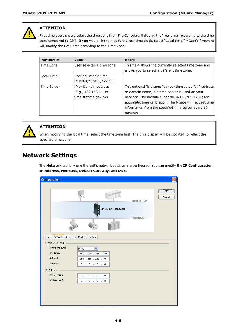
Network Settings The Network tab is where the unit’s network settings are configured. You can modify the IP Configuration, IP Address, Netmask, Default Gateway, and DNS.

MGate 5101-PBM-MN Configuration (MGate Manager)
4-9
Ethernet Settings
Parameter Value Notes IP Configuration Static IP, DHCP, BOOTP Select “Static IP” if you are using a fixed IP address.
Select one of the other options if the IP address is set dynamically.
IP Address 192.168.127.254 (or other 32-bit number)
The IP (Internet Protocol) address identifies the server on the TCP/IP network.
Netmask 255.255.255.0 (or other 32-bit number)
Th netmask identifies the server as belonging to a Class A, B, or C network.
Gateway 0.0.0.0 (or other 32-bit number)
The gateway is the IP address of the router that provides network access outside the server’s LAN.
DNS Server
Parameter Value Notes DNS Server 1 0.0.0.0
(or other 32-bit number) This is the IP address of the primary domain name server.
DNS Server 2 0.0.0.0 (or other 32-bit number)
This is the IP address of the secondary domain name server.
PROFIBUS Settings The MGate 5101-PBM-MN PROFIBUS interface supports DPV1 master protocol and is compliant with IEC 61158. Before the MGate can communicate with PROFIBUS slave devices, you need to input the PROFIBUS parameters for all connected devices, such as slave address and I/O module. To configure the slave devices, click the PROFIBUS Settings button. The new configuration window for the PROFIBUS network will open.

MGate 5101-PBM-MN Configuration (MGate Manager)
4-10
The PROFIBUS Settings window is divided into three sections.
Left panel: Shows a tree list for recognized devices that the GSD file has already imported into the host computer through MGate Manager. If the target PROFIBUS slave devices that you want to connect to this MGate are not in the list, import the GSD file first.
Right top panel: Shows the PROFIBUS network controlled by this MGate. To begin with, there is only one device, the PROFIBUS master device, which is also the MGate the user is configuring. To add new devices to this network, drag the device from the left panel into this panel. For this device to work correctly, you need to configure this device’s PROFIBUS parameters, including slave address and baud rate.
Right bottom panel: Shows the “device lists” or “the “I/O module list of the selected slave device in the top panel”.
Adding new PROFIBUS slave devices to the PROFIBUS network
Take the following steps to add a new PROFIBUS slave device to the PROFIBUS network. Detailed instructions for each step are given below.
1. Add new GSD files for different PROFIBUS slave devices with the GSD management function. If several devices use the same GSD file, you only need to run this process once. This means that if the GSD file is already in the GSD Management window list, you can skip this step.
2. Load the PROFIBUS Settings window. 3. Add a new device to the PROFIBUS network. 4. Configure the PROFIBUS address. 5. Configure the I/O module for the target PROFIBUS slave device that you want to access. 6. Run steps 3 to 5 for each PROFIBUS slave device. 7. Save the configuration and exit the PROFIBUS Settings function.

MGate 5101-PBM-MN Configuration (MGate Manager)
4-11
Step 1: Add a new GSD file (if necessary) A GSD file is a standard device description file for a PROFIBUS device. It includes all important device information and is provided by the device’s manufacturer. If you want to configure a PROFIBUS device for a PROFIBUS network, import the GSD file into the PROFIBUS network configuration software. If several devices use the same GSD file, you only need to import it once. This means that if the GSD file is already in the GSD Management window list, you can skip this step. MGate Manager provides a function, GSD Management, to manage GSD files.
To launch the GSD Management interface, click the GSD Management button from MGate Manager’s main window.
To add a GSD file, click Add and then assign the path where the GSD file is located. To delete a GSD file, select the GSD file and then click Remove.

MGate 5101-PBM-MN Configuration (MGate Manager)
4-12
Step 2: Load the PROFIBUS Settings window To further configure the PROFIBUS, click the PROFIBUS Settings button. The new configuration window for the PROFIBUS network will pop up.
Step3: Add a new device to the PROFIBUS network If you have already added the GSD file of the PROFIBUS device into MGate Manager correctly, you will see the devices listed in the left panel tree. The icon in the right panel shows the current connection status of the MGate device. Initially, only one device, the MGate 5102-PBM-PN PROFIBUS master, will be shown.

MGate 5101-PBM-MN Configuration (MGate Manager)
4-13
To add the device to the PROFIBUS network shown in the right panel above, drag the device from the left panel and drop it into the right panel. The device will then be shown beneath the network icon depicted in the right panel.
To remove the device from the PROFIBUS network (depicted at the top of the right panel in the figure above), select the device and press the Delete key.
AutoScan Function
The MGate Manager Utility also provides a PROFIBUS automatic scanning function so that the MGate device can automatically gather information about the PROFUBUS slaves that are connected to the network. When the scan is complete, you can change the detected slave devices to the bus configurations and download them to the Master.
Click the AutoScan button; the MGate device will display all the devices on the PROFIBUS network with configured I/O modules in a new window. You can click the top checkbox to select all, or select specific checkboxes for each signal device. When you click the OK button, the selected device and related I/O modules will be added to the PROFIBUS network configuration. This function eliminates the need to add slave devices manually one by one.
If you use the AutoScan function, you can skip Step 3 to Step 6, and go directly to Step 7.
MGate 5101-PBM-MN Configuration (MGate Manager)
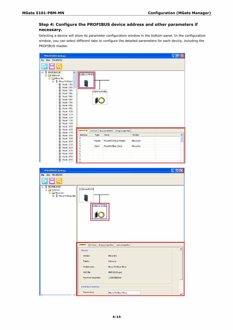
4-14
Step 4: Configure the PROFIBUS device address and other parameters if necessary. Selecting a device will show its parameter configuration window in the bottom panel. In the configuration window, you can select different tabs to configure the detailed parameters for each device, including the PROFIBUS master.
MGate 5101-PBM-MN Configuration (MGate Manager)
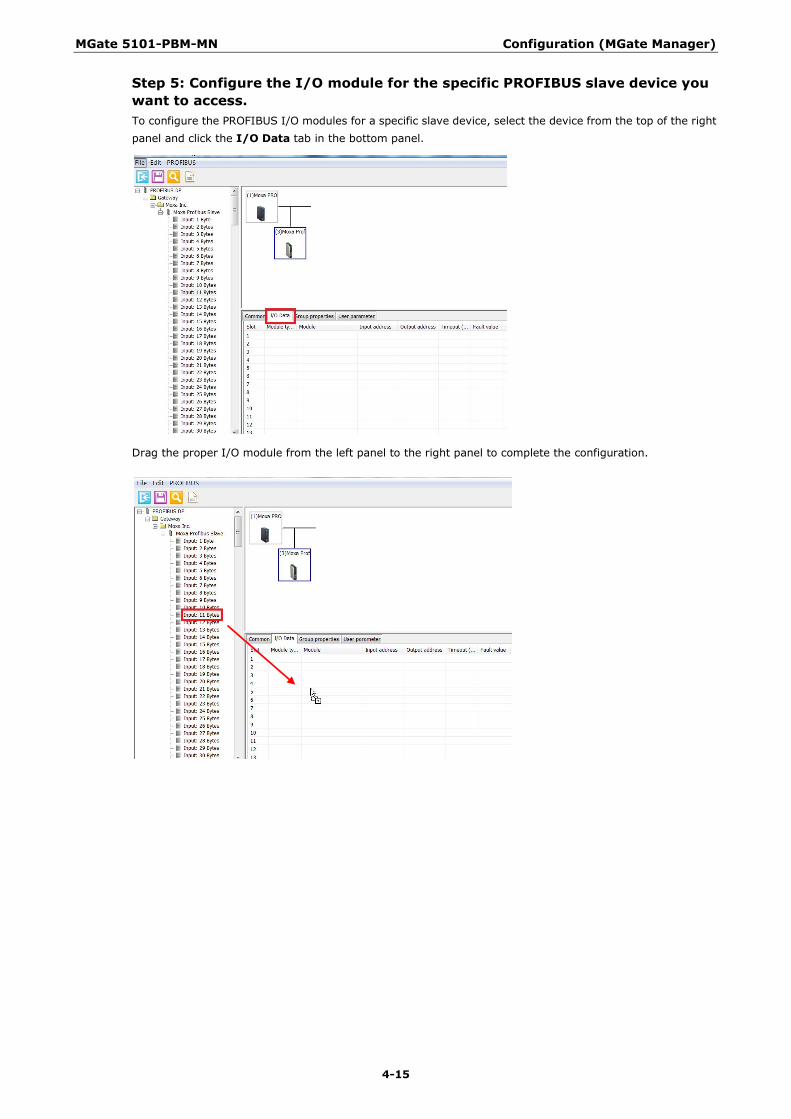
4-15
Step 5: Configure the I/O module for the specific PROFIBUS slave device you want to access. To configure the PROFIBUS I/O modules for a specific slave device, select the device from the top of the right panel and click the I/O Data tab in the bottom panel.
Drag the proper I/O module from the left panel to the right panel to complete the configuration.

MGate 5101-PBM-MN Configuration (MGate Manager)
4-16
The added I/O device will appear in the lower portion of the right panel.
At this point, you can configure device parameters, including the slave address and I/O modules. To configure each I/O module in detail, double click the I/O module to display the configuration dialog. In the dialog box, configure the internal memory address Offset and Fault values. To configure these parameters, refer to the Data Exchange Between PROFINET and PROFIBUS and Fault Value Configuration in the PROFIBUS Output Module sections.
To remove the I/O modules, select the I/O module and press the Delete key.
MGate 5101-PBM-MN Configuration (MGate Manager)
4-17
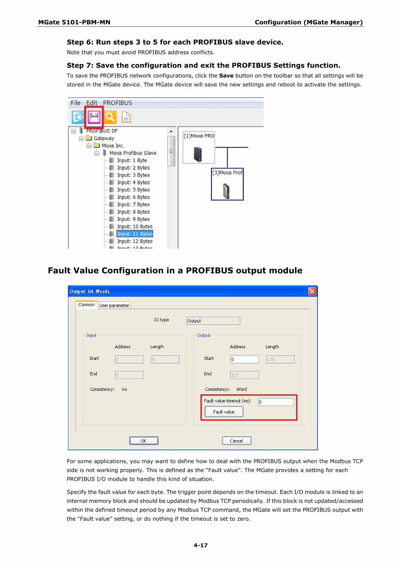
Step 6: Run steps 3 to 5 for each PROFIBUS slave device. Note that you must avoid PROFIBUS address conflicts.
Step 7: Save the configuration and exit the PROFIBUS Settings function. To save the PROFIBUS network configurations, click the Save button on the toolbar so that all settings will be stored in the MGate device. The MGate device will save the new settings and reboot to activate the settings.
Fault Value Configuration in a PROFIBUS output module
For some applications, you may want to define how to deal with the PROFIBUS output when the Modbus TCP side is not working properly. This is defined as the “Fault value”. The MGate provides a setting for each PROFIBUS I/O module to handle this kind of situation.
Specify the fault value for each byte. The trigger point depends on the timeout. Each I/O module is linked to an internal memory block and should be updated by Modbus TCP periodically. If this block is not updated/accessed within the defined timeout period by any Modbus TCP command, the MGate will set the PROFIBUS output with the “Fault value” setting, or do nothing if the timeout is set to zero.
MGate 5101-PBM-MN Configuration (MGate Manager)
4-18
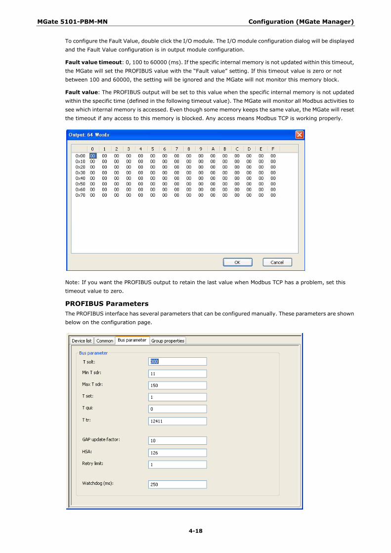
To configure the Fault Value, double click the I/O module. The I/O module configuration dialog will be displayed and the Fault Value configuration is in output module configuration.
Fault value timeout: 0, 100 to 60000 (ms). If the specific internal memory is not updated within this timeout, the MGate will set the PROFIBUS value with the “Fault value” setting. If this timeout value is zero or not between 100 and 60000, the setting will be ignored and the MGate will not monitor this memory block.
Fault value: The PROFIBUS output will be set to this value when the specific internal memory is not updated within the specific time (defined in the following timeout value). The MGate will monitor all Modbus activities to see which internal memory is accessed. Even though some memory keeps the same value, the MGate will reset the timeout if any access to this memory is blocked. Any access means Modbus TCP is working properly.
Note: If you want the PROFIBUS output to retain the last value when Modbus TCP has a problem, set this timeout value to zero.
PROFIBUS Parameters The PROFIBUS interface has several parameters that can be configured manually. These parameters are shown below on the configuration page.

MGate 5101-PBM-MN Configuration (MGate Manager)
4-19
Timing settings
Parameter Value Notes T Slot The unit is 100 μs. The maximum time that the PROFIBUS master must wait for a
slave response.
Min T SDR The unit is bits time, ranging from 11 to 255.
The minimum delay time for the PROFIBUS slave device to reply to the master’s request.
Max T SDR The unit is bits time, ranging from 11 to 255.
The maximum delay time for the PROFIBUS slave device to reply to the master’s request.
T set Setup time. The time between an event and reply message.
T qui Quiet Time. The time a slave device must wait after the end of a frame before enabling its receiver.
T tr Target rotation time. The anticipated time for one token rotation on this PROFIBUS System, including allowances for high and low priority transactions, errors, and GAP maintenance.
GAP update factor
The number of token rounds between GAP maintenance (update) cycles.
HSA Highest Station Address (FDL Address)
Retry limit The maximum PROFIBUS retry count.
Watchdog (ms) The watchdog time will be transferred to the slave in the Set Parameter stage. The watchdog control mechanism in a DP-Slave takes care of that; if the master fails, the output is changed to safe state after the watchdog time expires.
SYNC and FREEZE Settings
SYNC: In data_exchange the previous output value will be transferred. The following output data will be stored and not be transferred until next SYNC command or UNSYNC command.
FREEZE: In data_exhange the last input value will be transferred. The following input data value will be stored into special buffer and will not be transferred.
Modbus Settings The MGate 5101-PBM-MN supports Modbus TCP’s slave and master modes. For slave mode, the MGate works as a server and waits for incoming connections from the Modbus TCP master. For master mode, the MGate works as a client and tries to establish a TCP connection with remote Modbus TCP devices. In this mode, you need to specify the IP address of the remote device and the relative Modbus command.

MGate 5101-PBM-MN Configuration (MGate Manager)
4-20
Slave Mode Settings
Parameters Value Description Slave ID 1 to 255 The Modbus address of this MGate.
TCP Port 0 to 65535 The local TCP port for this MGate.
Master Mode Settings
Parameters Value Description Initial Delay 0 to 65535 ms Some Modbus slaves may take more time to boot up than
other devices. For certain environments, this may cause the entire system to suffer from repeated exceptions during the initial boot-up. You can force the MGate to wait after booting up before sending the first request with the “Initial Delay” setting.
Response Timeout 10 to 12000 ms This is used to configure how long the MGate will wait for a response from a Modbus slave.
Max. retry 0 to 99 This is used to configure how many times the MGate will try to communicate with the Modbus slave.
Modbus Command Table To communicate with remote Modbus TCP slave devices, you need to specify the Modbus command for each device. For each Modbus read/write command, you also need to specify the internal memory address for data exchange. For a read command, the information received from a remote device will be updated into the specified internal memory address. For a write command, the data in the specified internal memory address will be sent to the remote device. The data will be used to update the remote device’s register.
Each remote device may need more than one command to communicate, so you will need to input all of the commands manually.
MGate 5101-PBM-MN Configuration (MGate Manager)
4-21
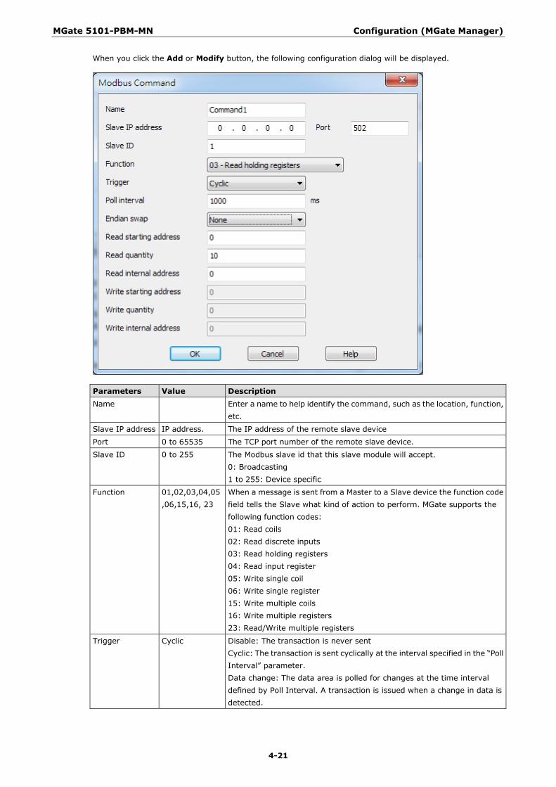
When you click the Add or Modify button, the following configuration dialog will be displayed.
Parameters Value Description Name Enter a name to help identify the command, such as the location, function,
etc.
Slave IP address IP address. The IP address of the remote slave device
Port 0 to 65535 The TCP port number of the remote slave device.
Slave ID 0 to 255 The Modbus slave id that this slave module will accept. 0: Broadcasting 1 to 255: Device specific
Function 01,02,03,04,05,06,15,16, 23
When a message is sent from a Master to a Slave device the function code field tells the Slave what kind of action to perform. MGate supports the following function codes: 01: Read coils 02: Read discrete inputs 03: Read holding registers 04: Read input register 05: Write single coil 06: Write single register 15: Write multiple coils 16: Write multiple registers 23: Read/Write multiple registers
Trigger Cyclic Disable: The transaction is never sent Cyclic: The transaction is sent cyclically at the interval specified in the “Poll Interval” parameter. Data change: The data area is polled for changes at the time interval defined by Poll Interval. A transaction is issued when a change in data is detected.
MGate 5101-PBM-MN Configuration (MGate Manager)
4-22
Parameters Value Description Poll interval 100 to
1200000ms Polling interval in milliseconds; since the module sends all requests in turns, the actual polling interval also depends on the number of requests in the queue and their parameters.
Endian Swap None, Byte, Word, ByteWord
Data Byte Swapping None: Don't need to swap Byte: 0x0A, 0x0B, 0x0C, 0x0D becomes 0x0D, 0x0C, 0x0B, 0x0A. Word: 0x0A, 0x0B, 0x0C, 0x0D becomes 0x0C, 0x0D, 0x0A, 0x0B. ByteWord: 0x0A, 0x0B, 0x0C, 0x0D becomes 0x0D, 0x0C, 0x0B, 0x0A. There are two phases in changing ByteWord 1). 0x0A, 0x0B, 0x0C, 0x0D becomes 0x0B, 0x0A, 0x0D, 0x0C. 2). 0x0B, 0x0A, 0x0D, 0x0C becomes 0x0D, 0x0C, 0x0B, 0x0A.
Read starting address
Station Address. The range is from 0 to 65535
Read quantity Specifies how many quantities to read. There are two kinds of quantity units, bit and 16 bits, associated with the function field. The range is from 1 to 125.
Read internal address
This parameter specifies the location of the trigger byte in internal memory for the Read command.
Write starting address
Station Address. The range is from 0 to 65535
Write quantity Specifies how many quantities to write. There are two kinds of quantity units, bit and 16 bits, associated with the function field. The range is from 1 to 121.
Write internal address
This parameter specifies the location of the trigger byte in internal memory for the Write command.
To remove a Modbus command, click the specified command and then click the remove button.
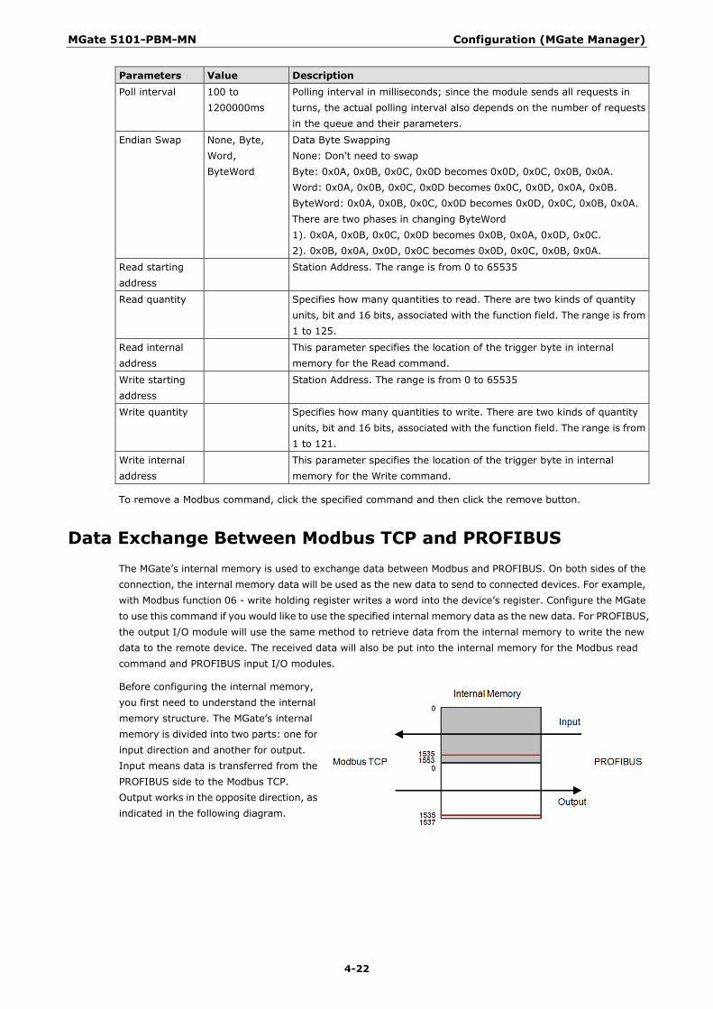
Data Exchange Between Modbus TCP and PROFIBUS The MGate’s internal memory is used to exchange data between Modbus and PROFIBUS. On both sides of the connection, the internal memory data will be used as the new data to send to connected devices. For example, with Modbus function 06 - write holding register writes a word into the device’s register. Configure the MGate to use this command if you would like to use the specified internal memory data as the new data. For PROFIBUS, the output I/O module will use the same method to retrieve data from the internal memory to write the new data to the remote device. The received data will also be put into the internal memory for the Modbus read command and PROFIBUS input I/O modules.
Before configuring the internal memory, you first need to understand the internal memory structure. The MGate’s internal memory is divided into two parts: one for input direction and another for output. Input means data is transferred from the PROFIBUS side to the Modbus TCP. Output works in the opposite direction, as indicated in the following diagram.

MGate 5101-PBM-MN Configuration (MGate Manager)
4-23
Internal Memory Address The MGate 5101-PBM-MN can support up to 1536 bytes of input and 1536 bytes of output data. Input addresses 1536 to 1553 are reserved for checking the status of the PROFIBUS Master or Slave. Output addresses 1536 to 1537 are used for changing the status of the PROFIBUS Master, as indicated in the following tables.
Input Data Memory
0 to 1535 Input Data
1536 to 1537 Status word bit 1:0 = Master Mode 00: Offline 01: Stop 10: Clear 11: Operate bit 15:2 reserved
1538 to 1553 Communication list 1538: bit 0..7= Slave 0..7 1539: bit 0..7 = Slave 8..15 … 1553: bit 0..5 = Slave 120..125 bit SET -> Slave is in data exchange bit CLEAR -> Slave is not in data exchange
Output Data Memory
0 to 1535 Output Data
1536 to 1537 Control word bit 1:0 = Master Mode 00: Reserved 01: Stop 10: Clear 11: Operate bit 15:2 reserved
Internal Memory Configuration for the PROFIBUS I/O Module For PROFIBUS, the assigned internal memory address is shown in the MGate Manager PROFIBUS Settings window. The Input addr. is the offset address in internal memory for the input direction. The Output addr. is the offset address in internal memory for the output direction. This address is assigned by MGate Manager automatically when the I/O module is just created, but you can modify it manually. However, when assigning an address manually, make sure that the new offset address does not overlap with the offset addresses assigned to other I/O modules.
Note the unit of the offset is bytes, which is different from the Modbus TCP configuration.
Internal Memory Configuration for Modbus TCP Master mode The Modbus TCP side has two different modes: slave mode and master mode. For Maser Mode, the internal memory configuration is in the Modbus command edit dialog.
The following example demonstrates this concept. Configure the I/O as shown below table. To use the input data to update the remote Modbus TCP device, use 06-write single register with 2 bytes. The “Internal address” can refer to the I/O module setting, so use 8 in this example. This command will retrieve the data in offset address 8 of internal memory as the new data to update the remote device. The data in this address will be updated cyclically by the PROFIBUS I/O module as you can see below. Because you want to transfer 4 bytes of data, for Modbus this means a length of two registers.

MGate 5101-PBM-MN Configuration (MGate Manager)
4-24
For the output direction, use the same way to configure the Modbus TCP command.
Internal Memory Configuration for Modbus TCP Slave Mode In slave mode, you do not need to configure any of the MGate’s Modbus command settings, but you need to know how to send the right Modbus TCP command to the MGate. In Modbus, you can either request “register data” or “bit data.” For register data, the length is two bytes (16 bits). For bit data, the length is 1 bit. So there are 01, 02, 05, 15 Modbus command support bit access, and 03, 04, 06, 16, 23 command support register access.
If you want to access the (n)th bit data in MGate internal memory offset (N) with Modbus bit access command: For bit access, the Modbus address should be N*8*2+n+1. (N, n is zero based)
If you want to access the data in MGate internal memory offset (N) with Modbus register access command: For bit access, the Modbus address should be N/2+1.
With the following example, if user want to access the 2nd bit of the input address 1. The users have to use the [01-read coil] command to read the address = 1*8*2+2+1 = 19. If users want to access the 4 bytes input data with Modbus register access command, the users have to use the [03-read holding register] command to read the address = 8/2+1 = 5 with length 2.
In host/Modbus Master In host/Modbus Master.
MGate 5101-PBM-MN Configuration (MGate Manager)
4-25
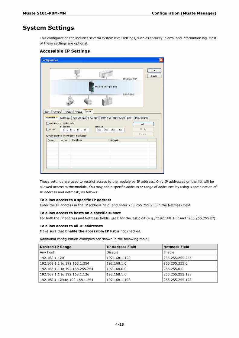
System Settings This configuration tab includes several system level settings, such as security, alarm, and information log. Most of these settings are optional.
Accessible IP Settings
These settings are used to restrict access to the module by IP address. Only IP addresses on the list will be allowed access to the module. You may add a specific address or range of addresses by using a combination of IP address and netmask, as follows:
To allow access to a specific IP address Enter the IP address in the IP address field, and enter 255.255.255.255 in the Netmask field.
To allow access to hosts on a specific subnet For both the IP address and Netmask fields, use 0 for the last digit (e.g., “192.168.1.0” and “255.255.255.0”).
To allow access to all IP addresses Make sure that Enable the accessible IP list is not checked.
Additional configuration examples are shown in the following table:
Desired IP Range IP Address Field Netmask Field Any host Disable Enable
192.168.1.120 192.168.1.120 255.255.255.255
192.168.1.1 to 192.168.1.254 192.168.1.0 255.255.255.0
192.168.1.1 to 192.168.255.254 192.168.0.0 255.255.0.0
192.168.1.1 to 192.168.1.126 192.168.1.0 255.255.255.128
192.168.1.129 to 192.168.1.254 192.168.1.128 255.255.255.128

MGate 5101-PBM-MN Configuration (MGate Manager)
4-26
System Log
This setting will enable the MGate firmware to record important events for future verification. The recorded information can only be displayed in the web console. See Chapter 5 for details.
The following events can be recorded:
Parameters Event System System Cold Start, System Warm Start.
Network DHCP/BOOTP Get IP/Renew, NTP Connect Fail, IP Conflict, Network Link Down.
Configuration Login Fail, IP Changed, Password Changed, Firmware Upgrade, SSL Certificate Import, Configuration Import/Export.
PROFIBUS PROFIBUS Communication logs.
Modbus Modbus Communication logs.
Users can view records from the web console or text mode console.

MGate 5101-PBM-MN Configuration (MGate Manager)
4-27
Auto Warning Setting
Auto Warning will be triggered in the event of a power failure or when Ethernet links are disconnected. When a checked trigger condition occurs, the MGate will open the circuit of the relay output. To enable an e-mail alert, configure the e-mail address on the E-mail Alert page. Likewise, to enable SNMP Trap alerts, configure SNMP trap server on the SNMP Trap page.
E-mail Alert

MGate 5101-PBM-MN Configuration (MGate Manager)
4-28
The MGate gateway will send a warning message via SMTP to the E-mail addresses entered on the E-mail Alert tab.
Parameters Value Description Mail server (SMTP) IP address or server name SMTP server’s IP address or server name
User name/ Password (an alphanumeric string) If the mail server requires user authentication, select the checkbox and enter the user name and password
From E-mail address [email protected] To show the sender’s e-mail address
To e-mail address 1–4 [email protected] Four e-mail recipients can be added to the list
SNMP Trap
The MGate gateway supports Simple Network Management Protocol (SNMP).
Parameters Value Description SMNP trap server IP or domain name
IP or domain name The MGate 5101-PBM-MN supports SNMP trap; enter the SNMP trap server IP or domain name
Trap version v1 Choose the trap version of the SNMP server, the default value is version 1
Trap community Use this field to designate the SNMP trap community

MGate 5101-PBM-MN Configuration (MGate Manager)
4-29
SNMP Agent
The SNMP Agent tag allows you to modify SNMP related settings.
LLDP Settings
MGate 5101-PBM-MN Configuration (MGate Manager)
4-30
The MGate gateway supports Link Layer Discovery Protocol (LLDP).
Parameters Value Description LLDP Enable/Disable To enable/disable the LLDP function
Message transmit 5 to 32768 Message transmit interval
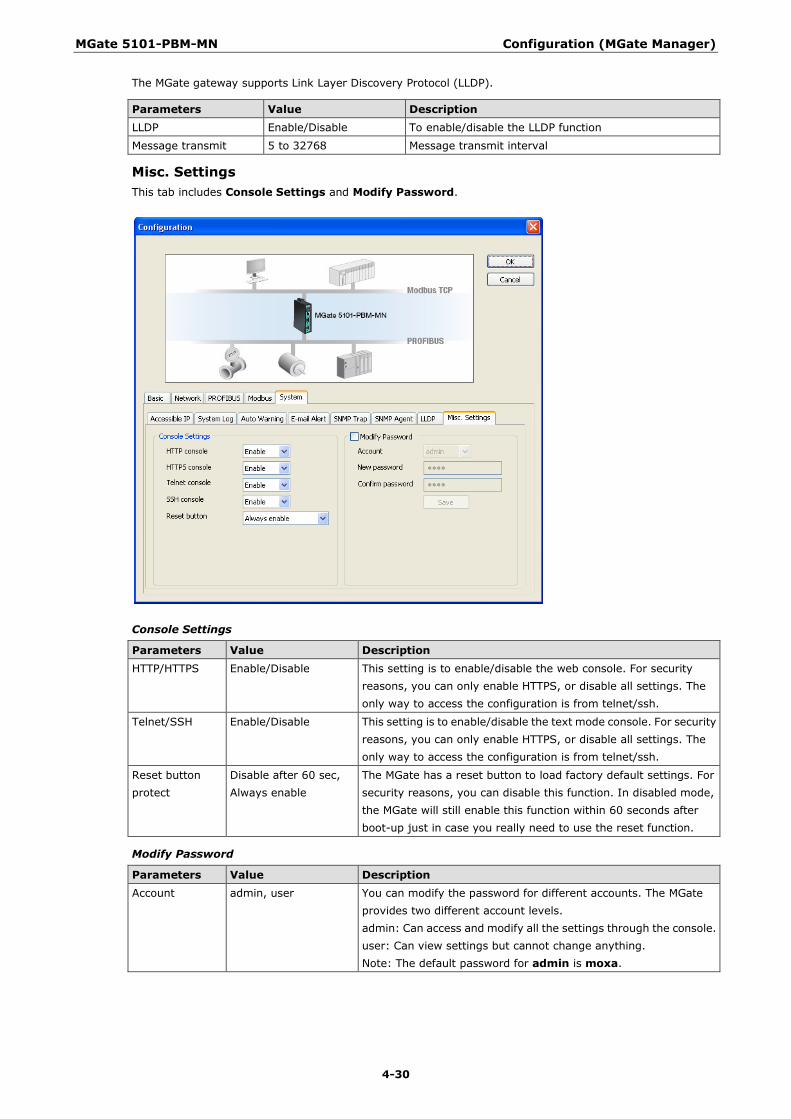
Misc. Settings This tab includes Console Settings and Modify Password.
Console Settings
Parameters Value Description HTTP/HTTPS Enable/Disable This setting is to enable/disable the web console. For security
reasons, you can only enable HTTPS, or disable all settings. The only way to access the configuration is from telnet/ssh.
Telnet/SSH Enable/Disable This setting is to enable/disable the text mode console. For security reasons, you can only enable HTTPS, or disable all settings. The only way to access the configuration is from telnet/ssh.
Reset button protect
Disable after 60 sec, Always enable
The MGate has a reset button to load factory default settings. For security reasons, you can disable this function. In disabled mode, the MGate will still enable this function within 60 seconds after boot-up just in case you really need to use the reset function.
Modify Password
Parameters Value Description Account admin, user You can modify the password for different accounts. The MGate
provides two different account levels. admin: Can access and modify all the settings through the console. user: Can view settings but cannot change anything. Note: The default password for admin is moxa.

MGate 5101-PBM-MN Configuration (MGate Manager)
4-31
Load Default Click Load Default to reset the unit to factory default values.
Click the OK to load default values, or click Cancel cancel the request.
MGate Manager will automatically execute a Broadcast Search to all MGate units on the LAN once the reset configuration is completed. Your MGate should reappear in the list of units.
ATTENTION
Load Default will completely reset the configuration of the unit, and all of the parameters you have saved will be deleted. Do not use this function unless you are sure you want to completely reset your unit.

MGate 5101-PBM-MN Configuration (MGate Manager)
4-32
Monitoring Modbus Activity For troubleshooting or management purposes, you can monitor the data passing through any MGate 5101-PBM-MN on the Modbus side. Data events will be logged as they pass through the gateway. Rather than simply echoing the data, MGate Manager presents the data in an intelligent, easily-understood format, with clearly designated fields including source, type, destination, contents, and more. Events can be filtered in different ways (Exception, Slave ID, Source, Function Code), and the complete log can be saved to a file for later analysis.
Open Traffic Monitor Window Select the unit that you wish to monitor and click Monitor to open the Traffic Monitor window.

MGate 5101-PBM-MN Configuration (MGate Manager)
4-33
In the Traffic Monitor window, click Start to begin live monitoring of the data passing through the selected MGate 5101-PBM-MN unit.
To stop capturing the log, press the Stop button.
Save Log to File To save the data log to a file, click Save. You may retrieve a saved log by clicking Load.

MGate 5101-PBM-MN Configuration (MGate Manager)
4-34
Diagnose The MGate also provides statistics for troubleshooting, especially for PROFIBUS slave devices. For most applications, the MGate will connect to several PROFIBUS slaves at the same time. If some devices don’t work well, it is difficult for users to know which device has the communication problem. Use this function to identify and solve problems immediately. Click the Diagnose button to open the diagnose window.
The diagnose windows, which include Modbus and PROFIBUS information, will be displayed.
For Modbus, different information will be displayed for master and slave settings.
For PROFIBUS, all configured devices will be displayed. Double click a slave device to display detailed information for that device.
This information displays the PROFIBUS DP diag_data information.
MGate 5101-PBM-MN Configuration (MGate Manager)
4-35
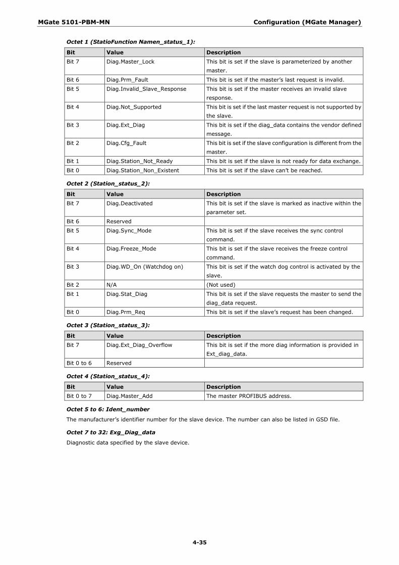
Octet 1 (StatioFunction Namen_status_1):
Bit Value Description Bit 7 Diag.Master_Lock This bit is set if the slave is parameterized by another
master.
Bit 6 Diag.Prm_Fault This bit is set if the master’s last request is invalid.
Bit 5 Diag.Invalid_Slave_Response This bit is set if the master receives an invalid slave response.
Bit 4 Diag.Not_Supported This bit is set if the last master request is not supported by the slave.
Bit 3 Diag.Ext_Diag This bit is set if the diag_data contains the vendor defined message.
Bit 2 Diag.Cfg_Fault This bit is set if the slave configuration is different from the master.
Bit 1 Diag.Station_Not_Ready This bit is set if the slave is not ready for data exchange.
Bit 0 Diag.Station_Non_Existent This bit is set if the slave can’t be reached.
Octet 2 (Station_status_2):
Bit Value Description Bit 7 Diag.Deactivated This bit is set if the slave is marked as inactive within the
parameter set.
Bit 6 Reserved
Bit 5 Diag.Sync_Mode This bit is set if the slave receives the sync control command.
Bit 4 Diag.Freeze_Mode This bit is set if the slave receives the freeze control command.
Bit 3 Diag.WD_On (Watchdog on) This bit is set if the watch dog control is activated by the slave.
Bit 2 N/A (Not used)
Bit 1 Diag.Stat_Diag This bit is set if the slave requests the master to send the diag_data request.
Bit 0 Diag.Prm_Req This bit is set if the slave’s request has been changed.
Octet 3 (Station_status_3):
Bit Value Description Bit 7 Diag.Ext_Diag_Overflow This bit is set if the more diag information is provided in
Ext_diag_data.
Bit 0 to 6 Reserved
Octet 4 (Station_status_4):
Bit Value Description Bit 0 to 7 Diag.Master_Add The master PROFIBUS address.
Octet 5 to 6: Ident_number
The manufacturer’s identifier number for the slave device. The number can also be listed in GSD file.
Octet 7 to 32: Exg_Diag_data
Diagnostic data specified by the slave device.
MGate 5101-PBM-MN Configuration (MGate Manager)
4-36
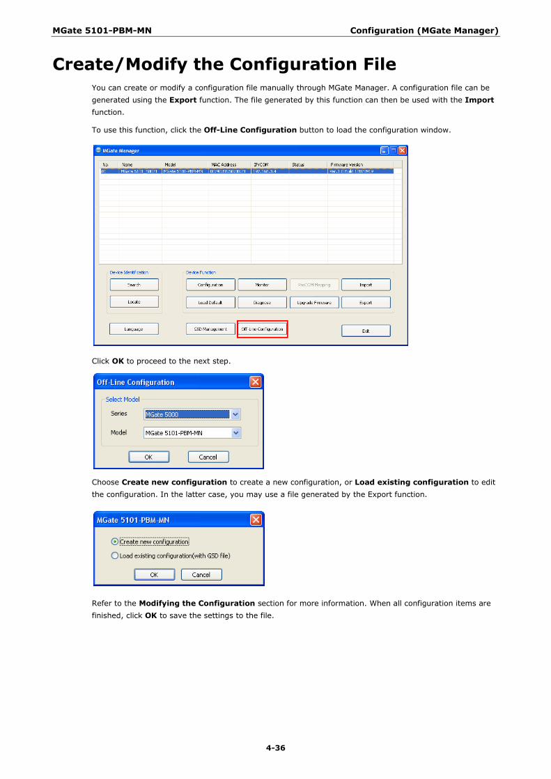
Create/Modify the Configuration File You can create or modify a configuration file manually through MGate Manager. A configuration file can be generated using the Export function. The file generated by this function can then be used with the Import function.
To use this function, click the Off-Line Configuration button to load the configuration window.
Click OK to proceed to the next step.
Choose Create new configuration to create a new configuration, or Load existing configuration to edit the configuration. In the latter case, you may use a file generated by the Export function.
Refer to the Modifying the Configuration section for more information. When all configuration items are finished, click OK to save the settings to the file.
MGate 5101-PBM-MN Configuration (MGate Manager)
4-37
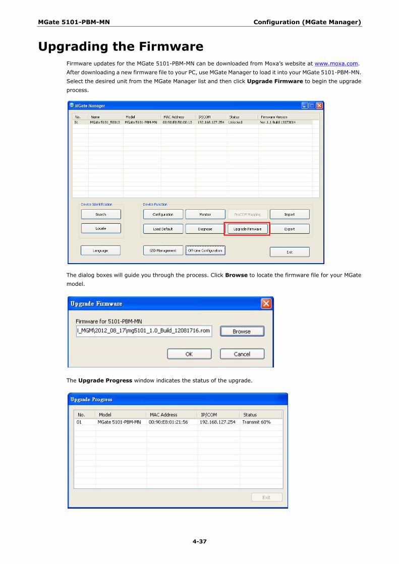
Upgrading the Firmware Firmware updates for the MGate 5101-PBM-MN can be downloaded from Moxa’s website at www.moxa.com. After downloading a new firmware file to your PC, use MGate Manager to load it into your MGate 5101-PBM-MN. Select the desired unit from the MGate Manager list and then click Upgrade Firmware to begin the upgrade process.
The dialog boxes will guide you through the process. Click Browse to locate the firmware file for your MGate model.
The Upgrade Progress window indicates the status of the upgrade.

MGate 5101-PBM-MN Configuration (MGate Manager)
4-38
Once the firmware has been successfully written to the unit, click Exit to close the Upgrade Firmware window. MGate Manager will automatically execute a Broadcast Search to all MGate units on the LAN. Your MGate should reappear in the list of units.
Import/Export The Import/Export configuration function is a convenient way to apply the same settings to units located at different sites. You can export the configuration as a file, and then import that configuration file into other units at any time.
Click the Export button to save all of the configuration settings and parameters of the MGate 5101-PBM-MN to an .ini file.
Use the text box and Browse button to set the filename and path, and then click OK.
If the export is successful, a confirmation message will pop up. Click OK to save the file.
MGate 5101-PBM-MN Configuration (MGate Manager)
4-39
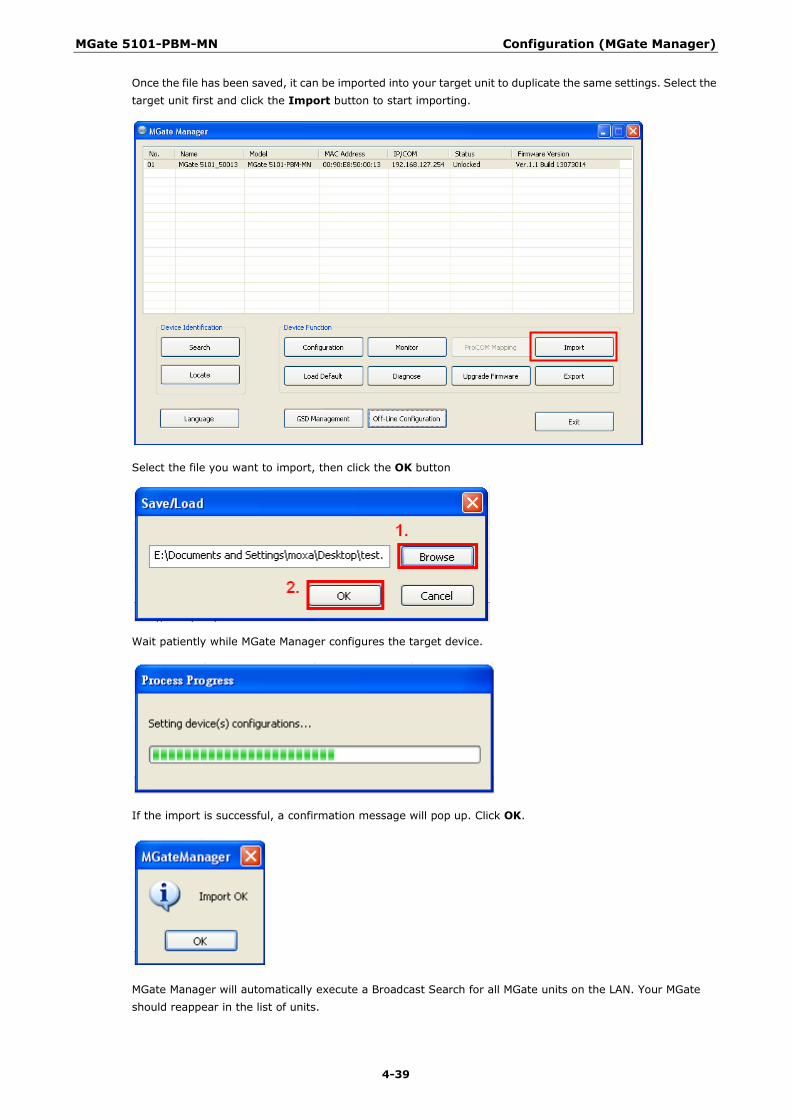
Once the file has been saved, it can be imported into your target unit to duplicate the same settings. Select the target unit first and click the Import button to start importing.
Select the file you want to import, then click the OK button
Wait patiently while MGate Manager configures the target device.
If the import is successful, a confirmation message will pop up. Click OK.
MGate Manager will automatically execute a Broadcast Search for all MGate units on the LAN. Your MGate should reappear in the list of units.

5 5. Configuration (Web Console)
The MGate 5101-PBM-MN also provides a web console for configuration, but only for limited items. For example, the PRFOFIBUS and Modbus TCP settings are not included in the web console and are only available in MGate Manager. Use a browser such as Microsoft Internet Explorer or Google Chrome to access the web console.
To connect to the MGate web console, open the browser and input the MGate’s IP address.
http://<MGate IP address>
or
https://<MGate IP address>
Input the account and password and then click Login. The account supports two types of users: admin and user. An “admin” account can modify all of the settings, but a “user” account can only review the settings. A “user” account cannot modify the configuration. The default password for admin is moxa.
All available configuration items are listed in the menu in left panel. Click an item to display detailed options in right panel. To activate changes, click the Submit button before leaving the current page. The MGate may need to restart to activate the settings.
The following functions are the same as in the MGate Manager utility. Click the section listed in the right column for detailed information.
Function Where to find information Basic Settings Configure Device section.
Network Settings Network Settings section.
Protocol Settings - Modbus TCP Modbus section.
Protocol Settings - PROFIBUS PROFIBUS section.
System Management – Accessible IP List Accessible IP Settings section.
System Management – System Log Settings System Log section.
System Management – Auto Warning Settings Auto Warning section.
System Management - E-mail Alert E-mail Alert section.
System Management - SNMP Trap SNMP Trap section.
System Management - SNMP Agent SNMP Agent section.
System Management - LLDP Settings LLDP Settings section.
System Management – Misc. Settings - Console Settings Console Settings section.

MGate 5101-PBM-MN Configuration (Web Console)
5-2
Function Where to find information System Management – Misc. Settings - Change Password Modify Password section.
System Management – Maintenance - Firmware Upgrade Upgrading Firmware section.
System Management –Maintenance - Configuration Import Import/Export section.
System Management –Maintenance - Configuration Export Import/Export section.
System Management –Maintenance - Load Factory Default Load Default section.
PROFIBUS (Protocol Settings - PROFIBUS) PROFIBUS settings in the Web Console are very similar to what you see in MGate Manager. The device list is on the left side of the window and the current status of the MGate gateway is on the right side.
To add a device to the MGate gateway, drag the slave device to the list on the right side.

MGate 5101-PBM-MN Configuration (Web Console)
5-3
After you add the device to the MGate gateway, click the Edit button to edit related settings. See PROFIBUS Settings in Chapter 4 for a description of each function.
GSD Management (Protocol Settings - GSD Management)
To add a GSD file, click the Browse button to locate the directory, and then click Add to load the file. Once the GSD file has been added, you will be able to see all of the GSD files in the GSD file list. If you want to export all GSD files, click the Export button to store all of these GSD files.
PROFIBUS Control (System Management – Maintenance - PROFIBUS Control)
Users can configure the PROFIBUS interface of MGate to different operation mode. The available options are “Operate”, “Clear” and “Stop”. Users can click “Activate” to change the mode immediately. The PBM LED will also show the different the status for this change. Please refer to LED Indicators section.
This function is only available on web console and text mode console.
MGate 5101-PBM-MN Configuration (Web Console)
5-4
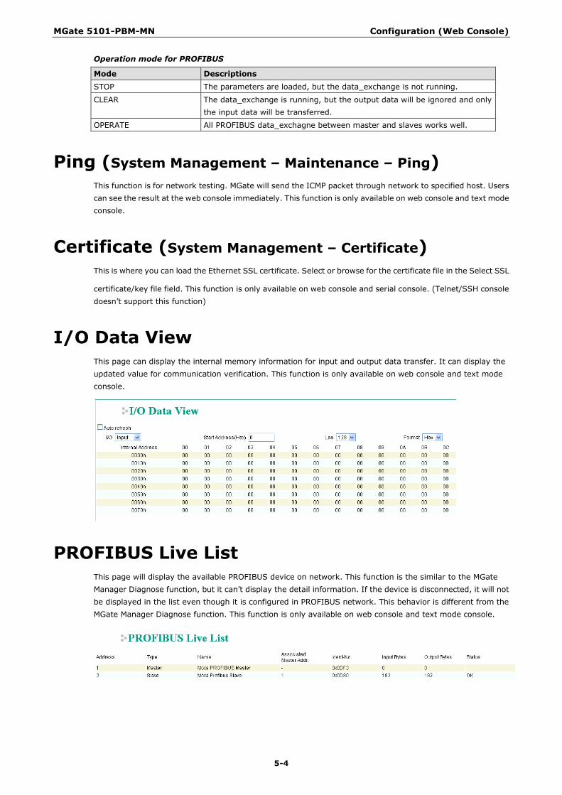
Operation mode for PROFIBUS
Mode Descriptions STOP The parameters are loaded, but the data_exchange is not running.
CLEAR The data_exchange is running, but the output data will be ignored and only the input data will be transferred.
OPERATE All PROFIBUS data_exchagne between master and slaves works well.
Ping (System Management – Maintenance – Ping) This function is for network testing. MGate will send the ICMP packet through network to specified host. Users can see the result at the web console immediately. This function is only available on web console and text mode console.
Certificate (System Management – Certificate) This is where you can load the Ethernet SSL certificate. Select or browse for the certificate file in the Select SSL
certificate/key file field. This function is only available on web console and serial console. (Telnet/SSH console doesn’t support this function)
I/O Data View This page can display the internal memory information for input and output data transfer. It can display the updated value for communication verification. This function is only available on web console and text mode console.
PROFIBUS Live List This page will display the available PROFIBUS device on network. This function is the similar to the MGate Manager Diagnose function, but it can’t display the detail information. If the device is disconnected, it will not be displayed in the list even though it is configured in PROFIBUS network. This behavior is different from the MGate Manager Diagnose function. This function is only available on web console and text mode console.

6 6. Configuration (Text Mode Console)
The MGate 5101-PBM-MN supports a text mode console with serial interface, telnet, and SSH protocol. The user interface is the same in all text mode consoles. Note that the text mode console does not support all configuration items. For example, PRFOFIBUS and Modbus TCP settings are not included in the text mode console; they are only available in MGate Manager.
For telnet and SSH, use HyperTerminal or PuTTY to connect to the MGate. Note that the telnet protocol will transfer the account and password information over the Internet using plain text, so telnet is essentially obsolete and should be replaced by the SSH protocol.
To connect to the MGate telnet/SSH console, load the telnet/SSH program and connect to the MGate IP address.
For the serial interface, use a null modem (crossover) cable to connect the serial port on the host to the serial console port on the MGate’s front of panel. The serial console parameters are 115.2kbps, none for parity, 8 data bits, and one stop bit. You can use a terminal program such as PComm Terminal Emulator or PuTTY to connect to the MGate serial console.
On the first page, input the account and password. The account supports two types of users: admin and user. An “admin” account can modify all of the settings, but a “user” account can only review the settings. A “user” account cannot modify the configuration. The default password for admin is moxa.
The text mode console will display the menu driven interface. Users can use arrow key to move the menu bar. To select the option, please press the “Enter” key to go next level menu. To go previous level menu, please press “Esc” key to quit. If necessary, MGate will need to restart to activate the setting.
MGate 5101-PBM-MN Configuration (Text Mode Console)
6-2
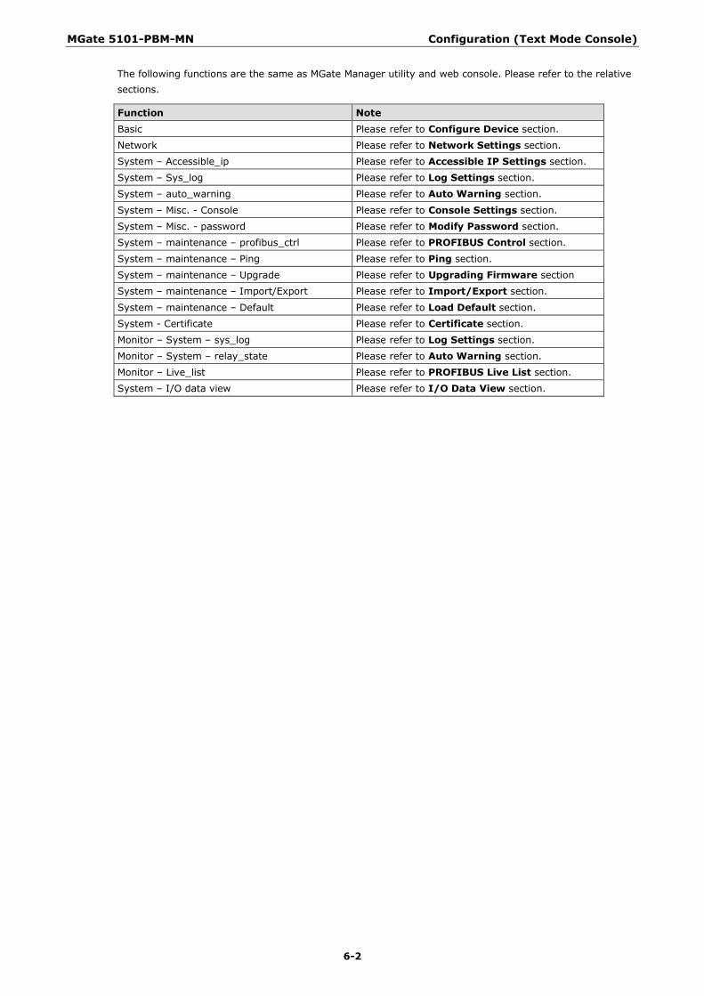
The following functions are the same as MGate Manager utility and web console. Please refer to the relative sections.
Function Note Basic Please refer to Configure Device section.
Network Please refer to Network Settings section.
System – Accessible_ip Please refer to Accessible IP Settings section.
System – Sys_log Please refer to Log Settings section.
System – auto_warning Please refer to Auto Warning section.
System – Misc. - Console Please refer to Console Settings section.
System – Misc. - password Please refer to Modify Password section.
System – maintenance – profibus_ctrl Please refer to PROFIBUS Control section.
System – maintenance – Ping Please refer to Ping section.
System – maintenance – Upgrade Please refer to Upgrading Firmware section
System – maintenance – Import/Export Please refer to Import/Export section.
System – maintenance – Default Please refer to Load Default section.
System - Certificate Please refer to Certificate section.
Monitor – System – sys_log Please refer to Log Settings section.
Monitor – System – relay_state Please refer to Auto Warning section.
Monitor – Live_list Please refer to PROFIBUS Live List section.
System – I/O data view Please refer to I/O Data View section.