megacoat msrs90 - kyocera group global … hard megacoat msrs90 multiple cutter hi efficiency...
TRANSCRIPT

MEGACOATMEGACOAT Hard
MSRS90Multiple Cutter
●Hi efficiency Notched and No-hand insert for MSRS90①Notched insert reduces cutting force reduction at the first pass
Stable machining without chatter②Smooth chip evacuation
Prevents fracture caused by biting chips③MEGACOAT for long tool life
High machining efficiency and cutting cost reduction
●Various expansive possibilities. Available for various type of application with custom order cutterMilling insert with corner-R (no hand)Available for various type of application such as shouldering (cutting angle: 90 degrees), high feed cutting (30 degrees), plunging and side cutter. (custom order)
1
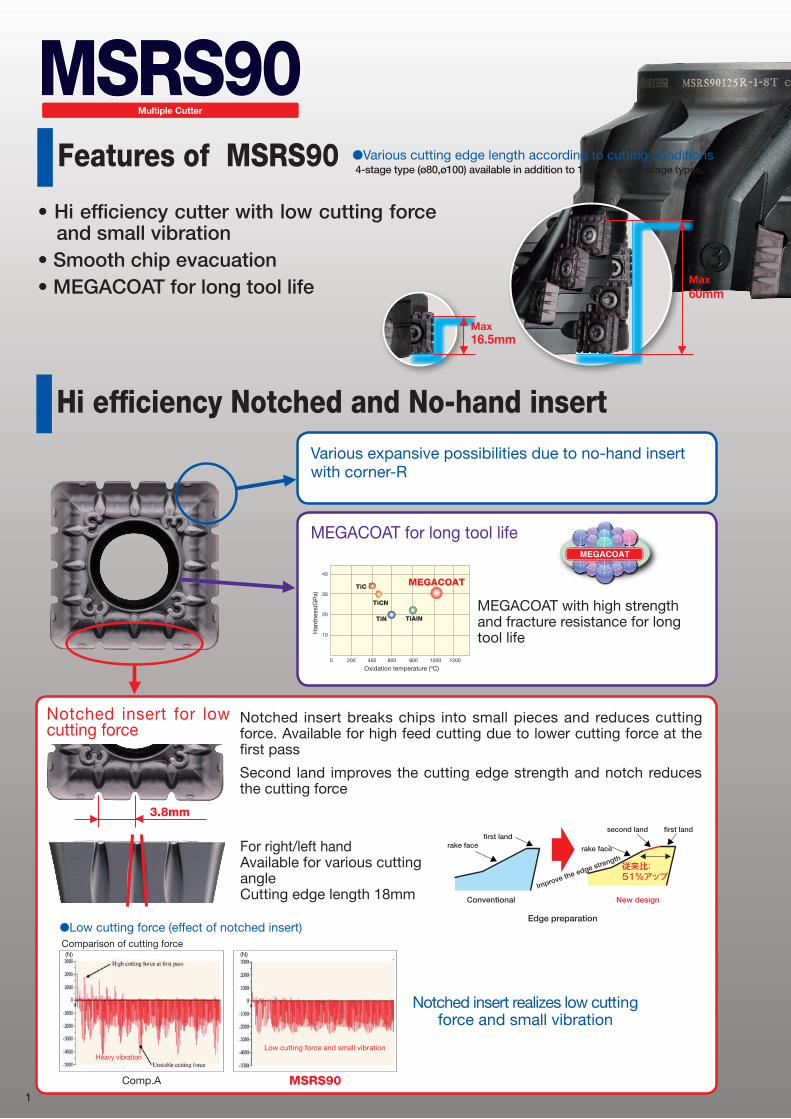
Hi efficiency Notched and No-hand insertVarious expansive possibilities due to no-hand insert with corner-R
MEGACOAT for long tool life
Notched insert for low cutting force
3.8mm
For right/left handAvailable for various cutting angleCutting edge length 18mm
Notched insert breaks chips into small pieces and reduces cutting force. Available for high feed cutting due to lower cutting force at the first pass
Second land improves the cutting edge strength and notch reduces the cutting force
MEGACOAT with high strength and fracture resistance for long tool life
Har
dne
ss(G
Pa)
Oxidation temperature (ºC)
40
30
20
10
0 200 400 600 800 1000 1200
TiCN
TiC
TiN
MEGACOAT
TiAlN
MEGACOATMEGACOAT Hard
Improve the edge strength
Conventional New design
Edge preparation
従来比: 51%アップ
second land first landfirst land
rake facerake face
●Low cutting force (effect of notched insert)Comparison of cutting force
Notched insert realizes low cutting force and small vibration
Comp.A MSRS90
Heavy vibrationLow cutting force and small vibration
(N) (N)
MSRS90Multiple Cutter
Features of MSRS90
Max16.5mm
Max60mm
• Hi efficiency cutter with low cutting force and small vibration
• Smooth chip evacuation• MEGACOAT for long tool life
●Various cutting edge length according to cutting conditions 4-stage type (ø80,ø100) available in addition to 1-stage and 2-stage types.

2
Insert cross-section.(Available for various type of application with new Inserts)Application Purpose 3 notches 4 notches Without
notch
General purpose1st Recommendation Standard type
NB3+
NB4
Low cutting force oriented
Low resistance type
NB3P+
NB4P
Emphasis on edge strength
Without notch(Possible to use notched insert)
( or ) +NB3 NB4
●Application range (standard toolholder)
MSR
MEC
MSRS90
fz(mm/t)
ap X
ae(
mm
)
Various expansive possibilities (custom order and standard)
●Shaft length determination
Face millLeft hand cutter
Face millRight hand cutter
High feed cutter
Plunge cutter
Shoulder cutter
Tapered cutter
Back milling cutter
Side cutter

3
■MSRS90Rake Angle
A.R. R.R.
+7° -10°
●Holder dimension
Description
Sto
ck
No. o
f Inse
rt
No. o
f Line
No. o
f Stag
e
Dimension(mm)Shape Weight
(kg)øD ød ød1 ød2 H E a b S ød3 ød4 ød5 ød6 G
Bor
e ød
:inch
With
out
Car
trid
ge
MSRS 90080R-1-4T ● 4 4 1
80 31.75 27 1860
32 8 12.7
16.5
- - - - -
fig.1 1.4
90080R-2-4T ● 8 4 2 31 fig.2 1.2
90080R-4-4T ● 16 4 4 90 60 fig.3 1.5
90100R-1-6T ● 6 6 1
100 38.1 39 2170
38 10 15.9
16.5 fig.1 2.3
90100R-2-6T ● 12 6 2 31 fig.2 2.1
90100R-4-6T ▲ 24 6 4 90 60 fig.3 3.2
90125R-1-8T ● 8 8 1125 38.1 55 - 60 38 10 15.9
16.5 fig.4 2.6
90125R-2-8T ▲ 16 8 2 31 fig.5 2.4
With
Car
trid
ge
MSRS 90160R-1-8T ● 8 8 1160 50.8 70 - 60 38 11 19.1
16.5 fig.4 4.3
90160R-2-8T ▲ 16 8 2 31 fig.5 4.1
90200R-1-10T ● 10 10 1200 47.625 - - 60 38 14 25.4
16.5 fig.6 6.7
90200R-2-10T ▲ 20 10 2 31 fig.7 6.6
90250R-1-12T ● 12 12 1250 47.625 - - 60 38 14 25.4
16.5 fig.6 12.6
90250R-2-12T ▲ 24 12 2 31 fig.7 12.5
90315R-1-14T ● 14 14 1315 47.625 - - 60 38 14 25.4
16.517 27 22 32 25
fig.8 16.1
90315R-2-14T ▲ 28 14 2 31 - 16.0
Bor
e ød
:mm
With
out
Car
trid
ge
MSRS 90080R-1-4T-M ● 4 4 1
80 27 20 1360
24 7 12.4
16.5
- - - - -
fig.1 1.3
90080R-2-4T-M ● 8 4 2 31 fig.2 1.1
90080R-4-4T-M ● 16 4 4 90 60 fig.3 1.4
90100R-1-6T-M ● 6 6 1
100 32 45 -60
30 8 14.4
16.5 fig.1 2.2
90100R-2-6T-M ● 12 6 2 31 fig.2 2.0
90100R-4-6T-M ▲ 24 6 4 90 60 fig.3 3.1
90125R-1-8T-M ● 8 8 1125 40 55 - 60 33 9.4 16.4
16.5 fig.4 2.6
90125R-2-8T-M 受 16 8 2 31 fig.5 2.4
With
Car
trid
ge
MSRS 90160R-1-8T-M ▲ 8 8 1160 60 70 - 60 33 9.4 16.4
16.5 fig.4 4.2
90160R-2-8T-M 受 16 8 2 31 fig.5 4.0
90200R-1-10T-M ▲ 10 10 1200 60 - - 60 38 15 25.9
16.5 fig.6 6.7
90200R-2-10T-M 受 20 10 2 31 fig.7 6.6
90250R-1-12T-M ▲ 12 12 1250 60 - - 60 38 15 25.9
16.5 fig.6 12.6
90250R-2-12T-M 受 24 12 2 31 fig.7 12.5
90315R-1-14T-M ▲ 14 14 1315 60 - - 60 38 15 25.9
16.517 27 22 32 25
fig.8 16.1
90315R-2-14T-M 受 28 14 2 31 - 16.0
●:Standard Stock ▲:Made to Order
bØd
aE
SH
Ød2Ød1ØD
0°
bØd
a
E
SH
Ød1ØD
0°
bØd
aE
SH
Ød2Ød1ØD
0°
bØd
aE
Ød3
Ød4S
H
ØD
0°ØC
G
SH
0°
ØD
E
b
a
G G
Ød3 Ød5
Ød4 Ød6
ØCØC1
ØdbØd
a
E
S
H
Ød1ØD
0°
SH
ØD
0°
bØd
aE
Ød2Ød1
bØd
aE
Ød3
Ød4
S
H
0°ØC
G
ØD
�g.1
�g.5 �g.6 �g.7 �g.8
�g.2 �g.3 �g.4
4
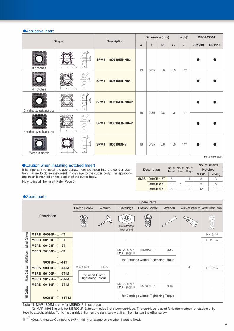
●Applicable Insert
Shape DescriptionDimension (mm) Angle(°) MEGACOAT
A T ød rε α PR1230 PR1210
3 notches A T
Ød
α
rε
SPMT 180616EN-NB3
18 6.35 6.8 1.6 11°
● ●
4 notches A TØd
α
rε
SPMT 180616EN-NB4 ● ●
3 notches Low resistance type A T
Ød
α
rε
SPMT 180616EN-NB3P
18 6.35 6.8 1.6 11°
● ●
4 notches Low resistance typeA T
Ød
α
rε
SPMT 180616EN-NB4P ● ●
Without notch A T
Ød
α
rε
SPMT 180616EN-V 18 6.35 6.8 1.6 11° ● ●
●:Standard Stock
Description No. of Insert
No. of Line
No. of Stage
No. of InsertsNotched
NB3(P) NB4(P)
MSRS 90100R-1-6T 6
6
1 3 3
90100R-2-6T 12 2 6 6
90100R-4-6T 24 4 12 12
●Spare parts
Description
Spare Parts
Clamp Screw Wrench Cartridge Clamp Screw Wrench Anti-seize Compound Arbar Clamp Screw
(Only bottom edge should be used)
MP-1
Witho
ut Ca
rtridg
e
MSRS 90080R-○ -4T
SB-60120TR TT-25L
- - -
MP-1
HH16×45
MSRS 90100R-○ -6T HH20×55
MSRS 90125R-○ -8T
-
With
Cartr
idge MSRS 90160R-○ -8T MAP-1806M※ 1 SB-40140TR DT-15
~
90315R-○ -14T
Witho
ut Ca
rtridg
e
MSRS 90080R-○ -4T-M
- - -
HH12×35
MSRS 90100R-○ -6T-M
-
MSRS 90125R-○ -8T-M
With
Cartr
idge MSRS 90160R-○ -8T-M MAP-1806M※ 1
SB-40140TR DT-15
~
90315R-○ -14T-M
Note) *1: MAP-1806M is only for MSR90..R-1..cartridge*2: MAP-1806S is only for MSR90..R-2..bottom edge (1st stage) cartridge. This cartridge is used for bottom edge (1st stadge) only.
How to attachcartridge:To fix the cartridge, tighten the slant screw at first, then tighten the other screw.
MP-1
∙Coat Anti-seize Compound (MP-1) thinly on clamp screw when insert is fixed.
for Insert ClampTightening Torque
for Cartridge Clamp Tightening Torque
for Cartridge Clamp Tightening Torque
●Caution when installing notched InsertIt is important to install the appropriate notched insert into the correct posi-tion. Failure to do so may result in damage to the cutter body. The appropri-ate insert is marked on the pocket of the cutter body.
How to install the insert Refer Page 5
MAP-1806S ※ 2
MAP-1806S ※ 2

5
■How to install the insert●Installation of Notched Inserts
When installing the inserts, match the insert’s top surface number to the number on the holder
Same numberSame number
●Insert Replacement Procedure
1.Remove chips or any dust from the insert pocket.2.Install inserts by pushing down the insert with a finger.
3.Please use only the attached T-wrench (TT-25L) for insert installation. *Inserts might not be clamped properly when using a different wrench.
Attached T-wrench (TT-25L)
Other wrench
for Insert Clamp Tightening Torque
4.After installing the insert, ensure there is no gap between the insert and the cartridge.
No gap Gap
5.After each use, additional clamping is recommended using the attached T-wrench.

6
■Recommended Cutting Conditions
Workpiece Material
Feed Rate (mm/t) Cutting Speed (m/min)
Standard typeNB3+NB4
Low resistance typeNB3P+NB4P
MEGACOAT
PR1230 PR1210
Soft Steel(SS) 0.1~0.2~0.25 0.1~0.2~0.25★
120~150~220
120~150~220
Carbon Steel(SxxC) 0.1~0.2~0.25 0.1~0.2~0.25★
100~150~200
100~150~200
Alloy Steel(SCM) 0.1~0.15~0.2 0.1~0.15~0.2★
100~150~200
100~150~200
Die Steel(SKD/NAK) 0.1~0.15~0.2 0.1~0.12~0.15★
100~150~180
100~150~180
Gray Cast Iron(FC) 0.1~0.2~0.3 0.1~0.2~0.25★
100~180~250★
100~180~250
Nodular Cast Iron(FCD) 0.1~0.2~0.25 0.1~0.18~0.2★
100~180~220★
100~180~220
Stainless Steel(SUS304) Not Recommended
Non-ferrous Metals Not Recommended
★:1st Recommendation :2nd Recommendation
■Various custom order cutters
High feed cutter
Plunge cutter Side cutter
45 degrees face mill
Tapered cutter
Various types of cutter design available to meet with your conditions, such as cutting diameter,
cutting angle and cutting edge length (stages), etc.

FCD450
Machining part
Industrial partsCutter and insertsMSRS90100R-1-6T(ø100 · 6 edges)SPMT180616EN-NB3/NB4
(PR1210)· Vc=150 m/min· ap × ae=6 × 65 mm· fz=0.15mm/t (Vf=430mm/min)
MSRS90(PR1210)Comp.B
Results· MSRS90 doubled the cutting efficiency compared with comp. B.· Comp. B machined with 2 passes (apxae=3x65mm). MSRS90 machined
with only 1 pass.· Cutting time reduced
Evaluation by the user
SKD
2000mm
50Worked Surface
Ship partsCutter and insertsMSRS90160R-1-8T(ø160 · 8 edges)SPMT180616EN-NB3/NB4
(PR1230)· Vc=150 m/min· ap × ae=10 × 10 ~50 mm· fz=0.1mm/t (Vf=240mm/min)
MSRS90(PR1230)Comp.D
Results· MSRS90 doubled the cutting efficiency compared with comp. D.· Comp. D: apxae=5x10~50mm, MSRS90 can increase ap twice due to low
cutting force.· MSRS90 can increase ap as well as cutting speed (Vc=150). It resulted in
total cutting efficiency improvement. (time reduction)
Evaluation by the user
SCM420
500m
m
Construction machine partsCutter and insertsMSRS90125R-1-8T(ø125 · 8 edges)SPMT180616EN-NB3/NB4
(PR1230)· Vc=200 m/min· ap × ae=10 × 50 mm· fz=0.1mm/t (Vf=400mm/min)
MSRS90(PR1230)Comp.C
Results· MSRS90 improved cutting efficiency to 1.3 times compared with comp. C.· Comp. C: apxae=5x50mm· Tool cost reduced to 1/3 since comp. C is 2-cornered insert. MSRS90 reduced machining cost as well as improving cutting efficiency.
Evaluation by the user
SNCM
200
150
ø800
740
Power generator partsCutter and insertsMSRS90125R-1-8T(ø125 · 8 edges)SPMT180616EN-NB3/NB4
(PR1230)· Vc=160 m/min· ap × ae=10 × 0 ~20 mm· fz=0.15mm/t (Vf=500mm/min)
MSRS90(PR1230)Comp.E
Results· MSRS90 improved tool life to 1.5 times of comp. E.· Comp. E machined with 2 pass (apxae=12x0~10mm) with low cutting feed (Vf=400mm/min). MSRS90 improved cutting efficiency. (time reduction)
· Comp. E creates large noise due to large cutting force. MSRS90 reduced the cutting force and noise as well.
Evaluation by the user
107cc/min.
60cc/min.
153cc/min.
8 faces / edge
Chip removal 258cc/min.
Chip removal 120cc/min.
Chip removal 200cc/min.
12 faces /edge
■Case studies