flexural behaviour of notched steel beams repaired...
TRANSCRIPT
Scientia Iranica A (2015) 22(4), 1390{1401
Sharif University of TechnologyScientia Iranica
Transactions A: Civil Engineeringwww.scientiairanica.com
Flexural behaviour of notched steel beams repairedwith FRP plates: Parametric studies
M. Motaleb and M.Z. Kabir�
Department of Civil and Environmental Engineering, Amirkabir University of Technology, Tehran, P.O. Box 15875-4413, Iran.
Received 27 October 2013; received in revised form 22 September 2014; accepted 27 October 2014
KEYWORDSFE;Repair;Steel beams;Notch;FRP plate;Parametric study.
Abstract. The load carrying capacity in a damaged steel beam can be substantiallyincreased through repairing by attaching Fiber-Reinforced-Polymer (FRP) plates to tension ange. Such a repaired beam is generally failed by either debonding of the FRP plates fromthe steel ange or FRP rupture at the damage location due to the stress concentration.In this case, the e�ectiveness of repair signi�cantly depends on the repairing materialproperties, i.e. FRP and adhesive. This paper developed a Finite Element (FE) modeling ofdamaged steel beams repaired with FRP plates, and aimed to clarify the FRP and adhesiveproperties e�ects on beam recovery. The primary defect was simulated by inserting a notchthrough the tension ange at mid-span. To ensure the validity of the proposed numericalmodel, the results of numerical models were compared with those existing experimentalworks. A parametric study was performed to achieve a better understanding on thesensitivity of parameters which are responsible for exural behavior of the repaired beams.Studies showed that the in uence of the most investigated parameters on the response ofthe repaired beam is very notable, and considering in uential parameters in choosing thematerial for a FRP-repair leads to promising results in design consideration.c 2015 Sharif University of Technology. All rights reserved.
1. Introduction
In practice, steel beams are vulnerable to be exposedto various factors through which their capacity isdecreased such as fatigue crack, physical damage,corrosion, wrong cutting during construction, and soon. Carbon Fiber Reinforced Polymer (CFRP) com-posites as construction materials are being increasinglyconsidered for repairing and strengthening the existingstructures because of their key advantages, includ-ing high strength-to-weight ratio, corrosion resistance,light weight and high durability.
Even though the e�ciency of the bonded CFRPfor the strengthening and repair of steel structures hasbeen presented in a number of studies [1-13], it can
*. Corresponding author. Tel.: +98 21 64543016;Fax: +98 21 66414213E-mail address: [email protected] (M.Z. Kabir)
be seen that the technique is not yet as extensive asit is for the concrete members. Up to now, mostof the previous studies focused on the behavior ofthe strengthening e�ect of FRP on undamaged steelbeams. However, in some experimental studies, thein uence of CFRP plates on the strength of arti-�cially damaged steel beams has been investigated.In the experiments conducted by Tavakkolizadeh andSaadatmanesh [13], the ultimate load-carrying ca-pacities of damaged girders in which damage variedfrom 25% loss of the ange to 100%, signi�cantlyincreased by 80% compared to the intact beam. Liuand et al. [12] reported that an increase in sti�nessand plastic load of corroded steel members can beachieved from the application of CFRP laminates tothe tension ange of corroded steel members. Inanother experimental study [5,9], it was resulted thatattaching CFRP plate to tension ange of a notchedsteel beam increased its load carrying capacity up

M. Motaleb and M.Z. Kabir/Scientia Iranica, Transactions A: Civil Engineering 22 (2015) 1390{1401 1391
to 79% of that for the intact beam. Accordingto another experimental study conducted by Harriesand et al. [7], the externally bonded CFRP platesincreased the load required to cause yield at the rootof the notch to 137% of that of the unrepaired beam.Also, in the other detailed aspect of repairing themetallic members, some researchers have worked on�nding an e�cient patch repair which is very importantfrom both economic and technical point of view [14-17].
However, the limited knowledge of behavior insuch applications needs to be extended. The lackof knowledge about interaction between the behaviorof the damaged beam and the properties of repairingmaterials (i.e., mechanical and dimensional propertiesof FRP and adhesive layer) are some of the problemscontributing to the di�culty of having a clear viewtoward FRP-repair.
The aim of this paper is to recognize the contri-bution of each physical and mechanical parameter ofmaterials to behavior of repaired beams under mono-tonic loading. In this direction, a validated numericalmodeling was developed, approaching by incorporatingcausal factors in the behavior of beams. It was assumedthat a beam su�ered from an initial notch passedthrough its tension ange, and attaching FRP plates tonotched ange was implemented to recover the beambehavior. In order to simulate the damaged steel beam,a notch was cut through its tension ange at mid-span.The notch was inserted to re ect the reduction in theelastic sti�ness and the ultimate strength of the beam.In order to validating the FE results, various beamstested by other researchers were simulated to comparethe results.
2. Finite element model
The simply supported beams were modeled using theFE program ABAQUS version 6.10 [18] to simulate themechanical behavior of the repaired beams. To reducethe time consuming in analysis process, only half of thesteel beam were modeled in which necessary constraintswere assigned to nodes of the symmetric surface, asshown in Figure 1.
Figure 1. Model con�guration.
2.1. Information about modeling and elementsThe present study simulated the nonlinear mechanicalbehavior of the repaired steel beam subjected to fourpoints loading. The initial damage in a steel beam wasmodeled by geometrical cut extrusion in the bottom ange at the mid-span. The FE model consists ofthree parts: steel, adhesive and FRP as shown inFigure 1. For FRP and steel beams, four-node shellelements with reduced integration, S4R, were adopted.Cohesive behavior, as a feature of ABAQUS version6.10, which is suitable for modeling the behavior ofadhesive joints [18], was used to model the adhesivelayer (explained in Section 2.4.2). Figure 1 shows themodel con�guration as well as the inserted notch inwhich a half circle cutting above the notch was modeledto overcome convergences problems. It should be notedthat to have a better view, shell thickness with the scaleof unit is shown in Figure 1.
2.2. Boundary conditions and load applicationDisplacement-type boundary condition was used toapply the external loading to the beam. Two rigidsurfaces as supports were de�ned and individual refer-ence points were assigned to each of them, as shownin Figure 1. Fixing the degrees of freedom at referencepoints, the constraints were applied to the entire rigidpart and the reaction force transmitted to the referencepoint. In addition to satisfying simple support con-ditions, this approach enables us to record the exactamount of the reaction force throughout the loading.
2.3. Constraints and contact interactionsThe steel beam-support plate and steel beam-composite plate interfaces were modeled by surface-to-surface contact interaction type, describing a contactbetween two deformable surfaces or between a de-formable surface and a rigid surface. A friction modelwas used to de�ne the resisting against tangentialmotion of the surfaces in a mechanical contact analysis.The penalty friction formulation was selected to de�nethe friction coe�cients for steel-support.
2.4. Materials modeling2.4.1. SteelIn this study, steel member was taken into account asan elastic-plastic material with strain hardening. Atypical trilinear stress-strain diagram of steel is shownin Figure 2. The model was developed based on theMises yield surface, de�ned by giving the value of theuniaxial yield stress as a function of uniaxial equivalentplastic strain [19]. Also, the isotropic hardening modelwas used to de�ne the strain hardening of materials.
2.4.2. FRP composite materialAs mentioned earlier, CFRP plates were modeled usingshell elements. Composite layup was employed tospecify the thickness, the number of integration points,
1392 M. Motaleb and M.Z. Kabir/Scientia Iranica, Transactions A: Civil Engineering 22 (2015) 1390{1401
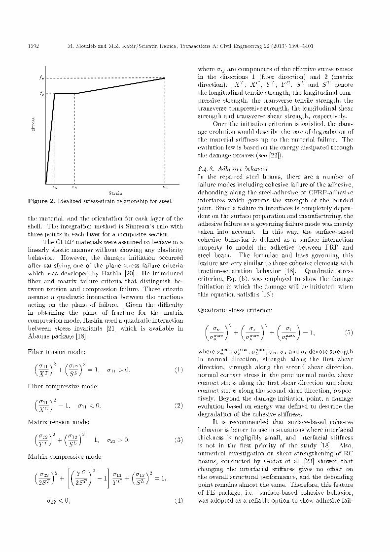
Figure 2. Idealized stress-strain relationship for steel.
the material, and the orientation for each layer of theshell. The integration method is Simpson's rule withthree points in each layer for a composite section.
The CFRP materials were assumed to behave in alinearly elastic manner without showing any plasticitybehavior. However, the damage initiation occurredafter satisfying one of the plane stress failure criteriawhich was developed by Hashin [20]. He introduced�ber and matrix failure criteria that distinguish be-tween tension and compression failure. These criteriaassume a quadratic interaction between the tractionsacting on the plane of failure. Given the di�cultyin obtaining the plane of fracture for the matrixcompression mode, Hashin used a quadratic interactionbetween stress invariants [21] which is available inAbaqus package [18]:
Fiber tension mode:� �11
XT
�2+��12
SL�2
= 1; �11 > 0: (1)
Fiber compressive mode:� �11
XC
�2= 1; �11 < 0: (2)
Matrix tension mode:��22
Y T�2
+��12
SL�2
= 1; �22 > 0: (3)
Matrix compressive mode:� �22
2ST�2
+
"�Y C
2ST
�2
� 1
#�11
Y C+��12
SL�2
= 1;
�22 < 0; (4)
where �ij are components of the e�ective stress tensorin the directions 1 (�ber direction) and 2 (matrixdirection). XT , XC , Y T , Y C , SL and ST denotethe longitudinal tensile strength, the longitudinal com-pressive strength, the transverse tensile strength, thetransverse compressive strength, the longitudinal shearstrength and transverse shear strength, respectively.
Once the initiation criterion is satis�ed, the dam-age evolution would describe the rate of degradation ofthe material sti�ness up to the material failure. Theevolution law is based on the energy dissipated throughthe damage process (see [22]).
2.4.3. Adhesive behaviorIn the repaired steel beams, there are a number offailure modes including cohesive failure of the adhesive,debonding along the steel-adhesive or CFRP-adhesiveinterfaces which governs the strength of the bondedjoint. Since a failure in interfaces is completely depen-dent on the surface preparation and manufacturing, theadhesive failure as a governing failure mode was merelytaken into account. In this way, the surface-basedcohesive behavior is de�ned as a surface interactionproperty to model the adhesive between FRP andsteel beam. The formulae and laws governing thisfeature are very similar to those cohesive elements withtraction-separation behavior [18]. Quadratic stresscriterion, Eq. (5), was employed to show the damageinitiation in which the damage will be initiated, whenthis equation satis�es [18]:
Quadratic stress criterion:��n�maxn
�2
+�
�s�maxs
�2
+�
�t�maxt
�= 1; (5)
where �maxn , �max
s , �maxt , �n, �s and �t denote strength
in normal direction, strength along the �rst sheardirection, strength along the second shear direction,normal contact stress in the pure normal mode, shearcontact stress along the �rst shear direction and shearcontact stress along the second shear direction, respec-tively. Beyond the damage initiation point, a damageevolution based on energy was de�ned to describe thedegradation of the cohesive sti�ness.
It is recommended that surface-based cohesivebehavior is better to use in situations where interfacialthickness is negligibly small, and interfacial sti�nessis not in the �rst priority of the study [18]. Also,numerical investigation on shear strengthening of RCbeams, conducted by Godat et al. [23] showed thatchanging the interfacial sti�ness gives no e�ect onthe overall structural performance, and the debondingpoint remains almost the same. Therefore, this featureof FE package, i.e. surface-based cohesive behavior,was adopted as a reliable option to show adhesive fail-
M. Motaleb and M.Z. Kabir/Scientia Iranica, Transactions A: Civil Engineering 22 (2015) 1390{1401 1393
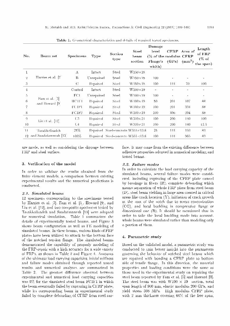
Table 1. Geometrical characteristics and details of repaired tested specimens.
No. Beam set Specimens Type Sectiontype
Steelbeam
section
Damagelevel
(% of theFlange'swidth)
CFRPmodulus(GPa)
Area ofCFRP(mm2)
Lengthof FRP(% of
the span)
1Harries et al. [7]
A Intact Steel W150�18 - - - -
2 B Unrepaired Steel W150�18 100 - - -
3 C Repaired Steel W150�18 100 144 70 100
4
Fam et al. [5]and Howard [9]
Control Intact Steel W100�19 - - - -
5 FC1 Unrepaired Steel W100�19 100 - - -
6 HC1F1 Repaired Steel W100�19 50 201 167 88
7 FC1F1 Repaired Steel W100�19 100 201 334 88
8 FC1F2 Repaired Steel W100�19 100 396 204 88
9Liu et al. [12]
U3 Repaired Steel W310�21 100 200 140 100
10 U4 Repaired Steel W310�21 100 200 140 12.5
11 Tavakkolizadehand Saadatamnesh [13]
25% Repaired Steel-concrete W355�13.6 25 144 193 83
12 100% Repaired Steel-concrete W355�13.6 100 144 965 83
ure mode, as well as considering the slippage betweenFRP and steel surface.
3. Veri�cation of the model
In order to validate the results obtained from the�nite element models, a comparison between existingexperimental results and the numerical predictions isconducted.
3.1. Simulated beams12 specimens corresponding to the specimens testedby Harries et al. [7], Fam et al. [5], Howard [9], andLiu et al. [12], and two composite specimens tested byTavakkolizadeh and Saadatmanesh [13] were adoptedfor numerical simulation. Table 1 summarizes thedetails of experimentally tested beams, and Figure 3shows beam con�guration as well as FE modeling ofsimulated beams. In these beams, various kinds of FRPplates have been utilized to attach to the bottom faceof the notched tension ange. The simulated beamsdemonstrated the capability of properly modeling ofthe FRP-repair with a high accuracy for a wide varietyof FRPs, as shown in Table 2 and Figure 4. Amountsof the ultimate load carrying capacities, initial sti�nessand failure modes obtained through reported testedresults and numerical analyses are summarized inTable 2. The greatest di�erence observed betweenexperimental and numerical load carrying capacitieswas 9% for the simulated steel beam FC1F1 in whichthe beam eventually failed by rupturing in CFRP plate,while its corresponding beam in experimental studyfailed by complete debonding of CFRP from steel sur-
face. It may come from the existing di�erence betweenadhesive properties adopted in numerical modeling andtested beams.
3.2. Failure modesIn order to calculate the load carrying capacity of thesimulated beams, several failure modes were consid-ered, including rupturing of the CFRP plate causedby breakage in �bers (R), complete debonding whichmeans separation of whole FRP plate from steel beam(D), steel beam yielding in large area created in criticalareas like crack location (Y), initiation of crack growthat the root of the notch due to stress concentration(CG), and local buckling in compressive ange ordistortional one (B). It should be mentioned that inorder to take the local buckling mode into account,whole beams were simulated rather than modeling onlya portion of them.
4. Parametric study
Based on the validated model, a parametric study wasconducted to gain better insight into the parametersgoverning the behavior of notched steel beams whichare repaired with bonding a CFRP plate to bottomside of tensile ange. In this direction, the materialproperties and loading conditions were the same asthose used in the experimental study on repairing thesteel beam reported by Fam et al. [5] and Haward [9].The steel beam was with W100 � 19 section, totalspan length of 900 mm, elastic modulus 200 GPa, andyield stress 398 MPa. High modulus CFRP plate,with 2 mm thickness covering 66% of the free span,
1394 M. Motaleb and M.Z. Kabir/Scientia Iranica, Transactions A: Civil Engineering 22 (2015) 1390{1401
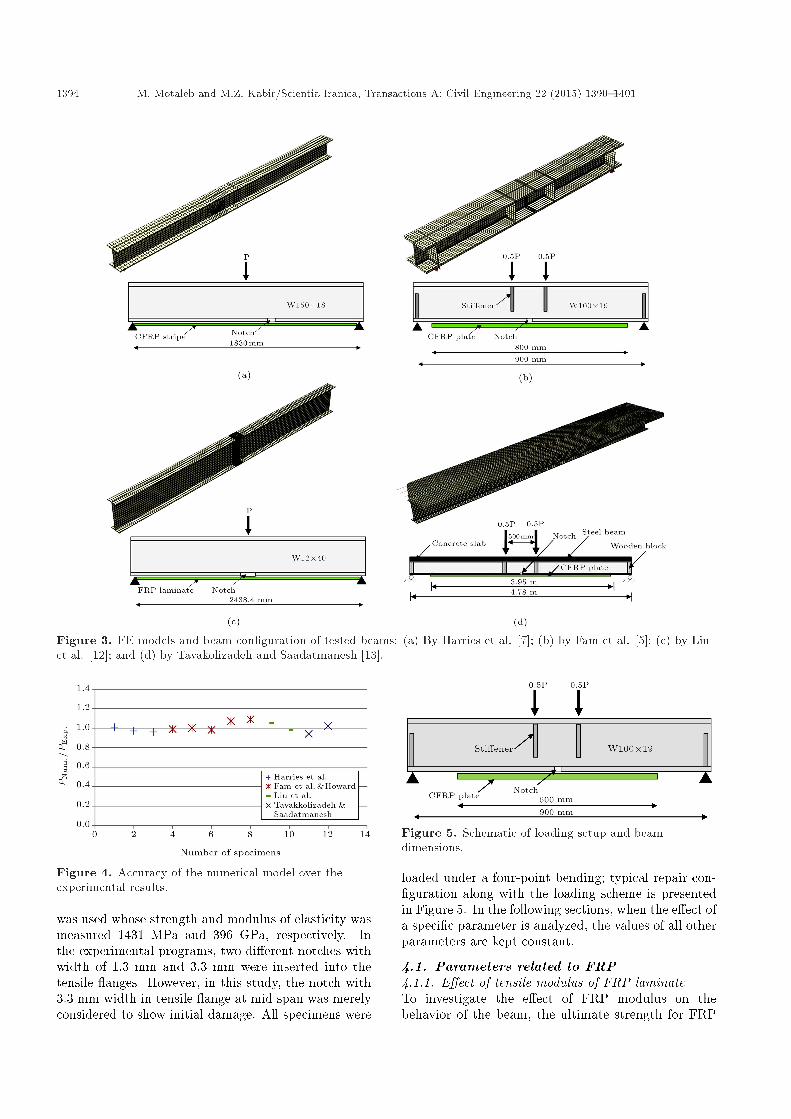
Figure 3. FE models and beam con�guration of tested beams: (a) By Harries et al. [7]; (b) by Fam et al. [5]; (c) by Liuet al. [12]; and (d) by Tavakolizadeh and Saadatmanesh [13].
Figure 4. Accuracy of the numerical model over theexperimental results.
was used whose strength and modulus of elasticity wasmeasured 1431 MPa and 396 GPa, respectively. Inthe experimental programs, two di�erent notches withwidth of 1.3 mm and 3.3 mm were inserted into thetensile anges. However, in this study, the notch with3.3 mm width in tensile ange at mid span was merelyconsidered to show initial damage. All specimens were
Figure 5. Schematic of loading setup and beamdimensions.
loaded under a four-point bending; typical repair con-�guration along with the loading scheme is presentedin Figure 5. In the following sections, when the e�ect ofa speci�c parameter is analyzed, the values of all otherparameters are kept constant.
4.1. Parameters related to FRP4.1.1. E�ect of tensile modulus of FRP laminateTo investigate the e�ect of FRP modulus on thebehavior of the beam, the ultimate strength for FRP
M. Motaleb and M.Z. Kabir/Scientia Iranica, Transactions A: Civil Engineering 22 (2015) 1390{1401 1395
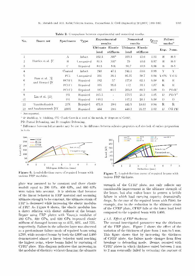
Table 2. Comparison between experimental and numerical results.
No. Beam set Specimens Type Experimentalresults
Numericalresults
PNumPExp
Failuremodesb
Ultimateload
Elasticsti�ness
Ultimateload
Elasticsti�ness
Exp. Num.
1Harries et al. [7]
A Intact 102.3 NRa 103.3 12.6 1.01 B B-Y2 B Unrepaired 81.8 NRa 79 10.6 0.97 B B-Y3 C Repaired 84.5 NR 80.7 10.9 0.96 B B-Y
4
Fam et al. [5]and Howard [9]
Control Intact 243 47.1 241.1 53.6 0.99 Y Y5 FC1 Unrepaired 101 36.1 95.35 38.7 0.94 Y-CG Y-CG6 HC1F1 Repaired 182 57 177.6 62.1 0.98 R R7 FC1F1 Repaired 105 55.6 112 59.1 1.07 R R8 FC1F2 Repaired 187 61.7 203.8 60.7 1.09 D PD-Rc
9Liu et al. [12]
U3 Repaired 165.5 - 173.5 21.2 1.05 D PD-Yc
10 U4 Repaired 149.5 - 147.2 20.1 0.98 D D
11 Tavakkolizadehand Saadatamnesh [13]
25% Repaired 471.8 19.6 441.5 18.65 0.94 R R12 100% Repaired 434 19.6 443.2 21.22 1.02 D CG-PD
a Not reported.b B: Buckling, Y: Yielding, CG: Crack Growth at root of the notch, R: Rupture of CFRP,PD: Partial Debonding, and D: complete Debonding.c Di�erences between failure modes may be due to the di�erence between adhesive properties and also lack of surface preparationin tests.
Figure 6. Load-de ection curve of repaired beams withvarious FRP modulus.
plate was assumed to be constant and three elasticmoduli equal to 200 GPa, 400 GPa, and 600 GPawere taken into account. It is obvious that becauseof the linear behavior in FRP material and assumingultimate strength to be constant, the ultimate strain ofFRP is decreased while increasing the elastic modulusof FRP. As Figure 6 shows, the elastic modulus hasa direct relation with elastic sti�ness of the beams.Repair using FRP plates with Young's modulus of200 GPa, 400 GPa, and 600 GPa improved elasticsti�ness of damaged beams up to 45%, 60%, and 72%,respectively. Failure in the adhesive layer was observedas a predominant failure mode of repaired beam usingE200, while repaired beams by both the E600 and E400demonstrated almost a linear behavior until reachingthe highest point, where beams failed by rupturing ofCFRP plate. This diagram indicates that increasing inthe modulus of elasticity without changing the ultimate
Figure 7. Load-de ection curve of repaired beams withvarious FRP thickness.
strength of the CFRP plate, not only re ects anyconsiderable improvement in the ultimate strength ofthe beam, but also makes beam to present a brittlefailure in which load carrying capacity dramaticallydrops. In the case of the repaired beam with E600, forexample, due to the reduction in the ultimate strainof the CFRP plate, CFRP fails at the lower load levelcompared to the repaired beam with E400.
4.1.2. E�ect of FRP thicknessThe second investigated parameter was the thicknessof the FRP plate. Figure 7 shows the e�ect of thevariation of the thickness of plate from 1 mm to 5 mm.This �gure shows that by increasing the thicknessof CFRP plate, the failure mode changes from �berbreakage to debonding mode. Beams, repaired withCFRP plates in which thickness varied between 1 mmto 2 mm eventually failed by occurring the rupture of

1396 M. Motaleb and M.Z. Kabir/Scientia Iranica, Transactions A: Civil Engineering 22 (2015) 1390{1401
CFRP plate at the mid-span, while the thicker platescompletely debonded from the surface of steel angeat the peak points. The distinction between rupturingand debonding can be seen in the descending partsof diagrams. Figure 7 shows that the repair withthickness of 2.5 mm almost restores the load carryingcapacity of damaged beam into an intact one. Ascan be seen in Figure 7, increasing the thickness ofCFRP plates from 2.5 mm to 4 mm led to strengthgrowth of beams which �nally dropped due to the �bercollapse. However, high thickness values of CFRP donot always lead to a higher gain in the load carryingcapacity. Figure 7 clearly shows this phenomenon thatwhen FRP thickness increases from 4 mm to 5 mm, anyenhancement of beam strength is gained, and causesa reduction in the ultimate load carrying capacity tooccur. The reason of this behavior will be discussed inSection 4.5.2.
4.1.3. E�ect of type of FRP plateAvailable FRP plates are of various types related totheir characteristics such as ultimate strain which is as-sociated with their modulus of elasticity. Therefore, inorder to reveal the in uence of FRP type on the repair-scheme, four commercially available FRP productswith various elastic moduli, consisting of GFRP (Glass-FRP) plates with modulus of elasticity 31 GPa andultimate strain 0.031, SM-CFRP (Standard Modulus)with modulus of elasticity 144 GPa and ultimate strain0.0148, HM-CFRP (High Modulus) with modulus ofelasticity 396 GPa and ultimate strain 0.00361, andUHM-CFRP (Ultra High Modulus) with modulus ofelasticity 514 GPa and ultimate strain of 0.00332 wereadopted. In this case, all of the dimensional propertiesof materials were assumed to be constant. Figure 8shows the load-de ection responses for repaired beamsin which UHM-CFRP plate enhances the strength ofthe beam by almost the intact one. It shows thatincreasing the elastic sti�ness is associated with theelastic modulus of each type of CFRP. The contributionof CFRP and the e�ect of its elastic modulus on exuralsti�ness are more pronounced after yielding steel incompressive ange and damaged area, compared tothe elastic range. However, the exural strength isnot always in direct relation with ultimate strength
Figure 8. Load-de ection curve of repaired beams withvarious FRP types.
Figure 9. Load-de ection curve of repaired beams withvarious FRP lengths.
of FRP. This is due to the reality that prematureadhesive failure mode tends to occur in more ductileFRP plates than high modulus FRPs. In this case,SMCFRP and HMCFRP plates, for example, led to69% and 112% increase in load carrying capacity whileSMCFRP plate had higher strength than HMCFRP.It should be noted that GFRP and SMCFRP platesutilized only 33% and 35% of their capacity at thetime of beam failure, respectively. The GFRP plate,however, is characterized by high ultimate strain, andallows the beam to have more ductility.
4.1.4. E�ect of FRP plate lengthAnother parameter of interest is bond length which isconsidered to be a variable parameter in an engineeringpractice which can easily be changed. The longerCFRP plate establishes, the greater area to transmitthe shear stress between steel and CFRP. As a result,it causes a growth in bond failure resistance capabilityof CFRP. As shown in Figure 9, in the case ofrepaired beam in which the length of CFRP plate was200 mm (L200), the beam showed a slight increase inload carrying capacity, since the premature debondingoccurred when almost half of CFRP capacity wasonly exploited. Initial sti�ness, however, signi�cantlyincreased because of the transmitting tension stressthrough CFRP plate at the notch location. In fact,CFRP plate distributes tensile stresses to the bottomsteel ange through creating a bridge across the notch.Hence the initial sti�ness increased by 40% comparedto the unrepaired beam. The repaired beam L300,also, failed due to the complete debonding of CFRPplate when 78% of its capacity was exploited. However,beams L400, L600, and L800 failed when the �berbreakage occurred at the notch location. CFRP platein L400 experienced a large area of debonding in thevicinity of notch, but �nally failed by rupturing ofCFRP. When the length of CFRP plate varied from400 to 800, there was negligible e�ect on load carryingcapacity enhancement. It comes from this reality thatstress concentration in the CFRP plate at the notchlocation does not allow beam to re ect the e�ect oflonger CFRP plate and causes the �ber breakage.Based on this study, it can be concluded that increase

M. Motaleb and M.Z. Kabir/Scientia Iranica, Transactions A: Civil Engineering 22 (2015) 1390{1401 1397
in bond length has a considerable e�ect on the strengthof the joint, but after a certain length, i.e. anchoragelength, no increase in the joint strength is observed. Ascan be seen in Figure 9, the optimum length of FRPplate is obtained when FRP covers 40% of span length,and leads to almost maximum load carrying capacity.
4.2. E�ect of adhesive strengthThe performance of the interface between FRP andsteel is one of the key factors in uencing the behaviorof the repaired beam. Adhesive strength in the case ofattaching CFRP plate to steel surface can have moree�ect on joint compared to the concrete structures,since unlike RC structures in which debonding failureof the FRP-to-concrete interface mostly occurs in theconcrete and a thin layer of concrete is detached,adhesive failure is often predominant in determiningbond strength of FRP-to-steel interface. However,the occurrence of cohesive failure within the adhesivelayer is valid as long as surface preparation is prop-erly implemented, so that FRP-to-adhesive and theadhesive-to-steel interfaces are strong enough to bearthe applied stresses. To demonstrate the e�ect ofadhesive strength, the strengths varying from 4 MPato 24 MPa were taken into account. It should benoted that there are also commercially available epoxyadhesives for FRP application with greater strengththan those of considered in this study, but usually theentire of their nominal strength due to the probablemanufacturing defaults as well as the lack of full surfacepreparation are not exploited.
As shown in Figure 10, an increase of bondstrength has considerable e�ect on the strength ofrepaired beam when it changes the failure modefrom debonding to rupture of CFRP plate. CFRPplates attached using adhesive with strength 4 MPato 12 MPa (Adh4-Adh12) experienced debonding fromsteel surface which initiated from notch in early stagesof loading and completed when it reached the debondedarea which initiated from the end of CFRP plate atfurther stages of loading. As can be seen in Figure 10,increasing adhesive strength higher than 16 MPa hadalmost no e�ect on the global behavior of the repaired
Figure 10. Load-de ection curve of repaired beams withvarious adhesive strengths.
Figure 11. Load-de ection curve of repaired beams withvarious lengths.
beams. It shows that this parameter can only in uenceon preventing CFRP from premature debonding failuremode and has negligible e�ect on the distribution ofaxial strain in the CFRP plate near the notch location.In other words, 16 MPa is the critical adhesive strengthat which the full e�ciency of the adhesively bondedplate was attained.
4.3. E�ect of steel beam lengthIn order to have a perspective toward the e�ect of beamlength on e�ciency of FRP-repair, four di�erent beamlengths were considered. Figure 11 shows the load-de ection response of repaired beams with the lengthvarying from 1 m to 4 m in which the CFRP platescovered 66% of the free span. This �gure indicatesthat attaching CFRP plate in a constant percent ofthe free span has almost the same comparative e�ect onimproving the load carrying capacity of various lengthsof beams. As shown in this �gure, the ultimate strengthin all repaired beams improved by about 115% com-pared to their corresponding damaged beams. Basedon this speci�c study, it can be concluded that inthe point of view of the comparative increasing in theload carrying capacity, short-span beams are able torepresent the behavior of analogous beams with greaterspan as long as the instability modes are prevented.
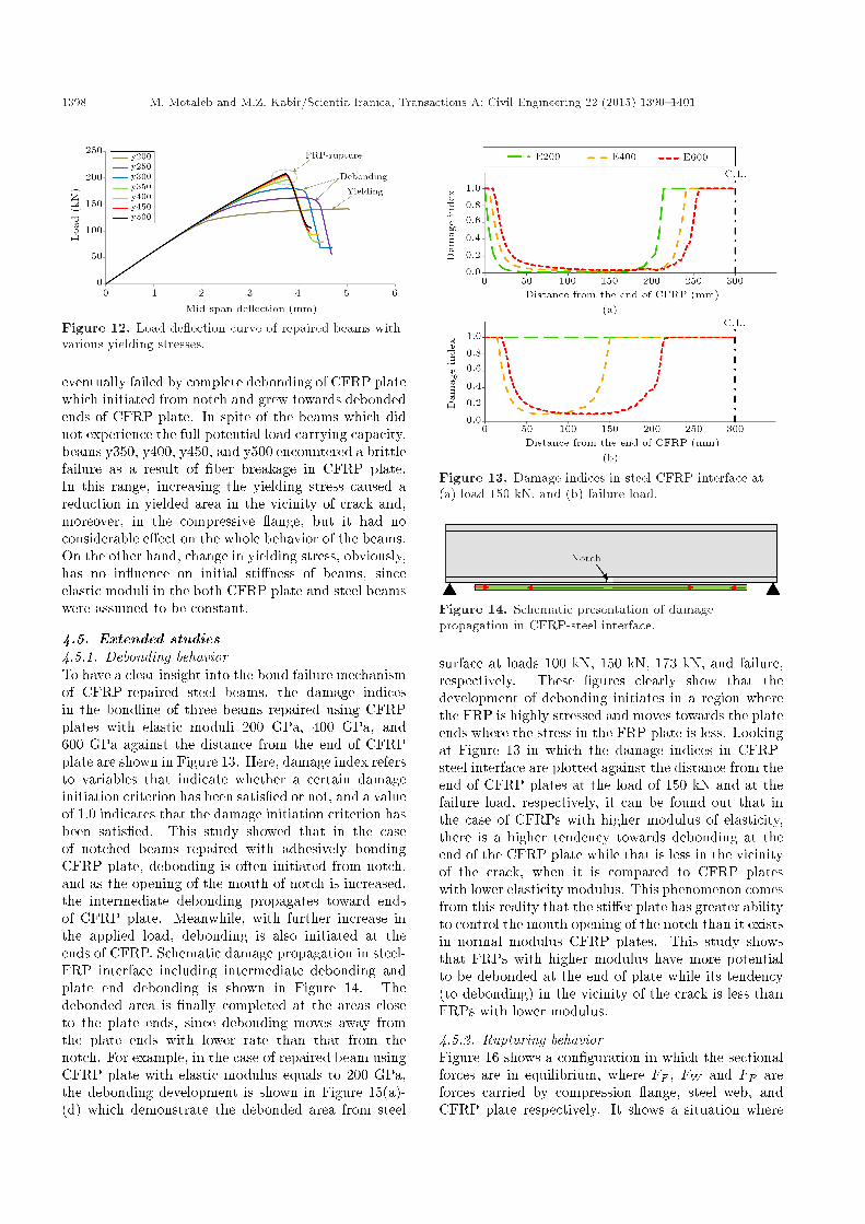
4.4. E�ect of strength of steel beamIn order to investigate the e�ect of the steel strengthon the e�ciency of CFRP-repair, the steel beams withdi�erent yielding stresses, fy = 200, 250, 300, 350,400, 450, 500 MPa (called y200 - y500), were adopted.These beams were repaired using HMCFRP plates.The corresponding load-de ection curves are plotted inFigure 12. This shows that the ultimate load increasesfor higher levels of the steel strength, when yieldingstress increases from 200 MPa to 350 MPa. However,it demonstrates a negligible growth in the ultimate loadwhen yielding stress varies from 400 MPa to 500 MPa.In fact, various ultimate loads come from changing inthe failure modes of repaired beams. In the case of y200(i.e. steel beam with yielding stress of 200 MPa), thebeam reached its ultimate strength when a large areain the compressive ange, as well as the notch vicinity,entered into plastic regime. Beams y250 and y300
1398 M. Motaleb and M.Z. Kabir/Scientia Iranica, Transactions A: Civil Engineering 22 (2015) 1390{1401
Figure 12. Load-de ection curve of repaired beams withvarious yielding stresses.
eventually failed by complete debonding of CFRP platewhich initiated from notch and grew towards debondedends of CFRP plate. In spite of the beams which didnot experience the full potential load carrying capacity,beams y350, y400, y450, and y500 encountered a brittlefailure as a result of �ber breakage in CFRP plate.In this range, increasing the yielding stress caused areduction in yielded area in the vicinity of crack and,moreover, in the compressive ange, but it had noconsiderable e�ect on the whole behavior of the beams.On the other hand, change in yielding stress, obviously,has no in uence on initial sti�ness of beams, sinceelastic moduli in the both CFRP plate and steel beamswere assumed to be constant.
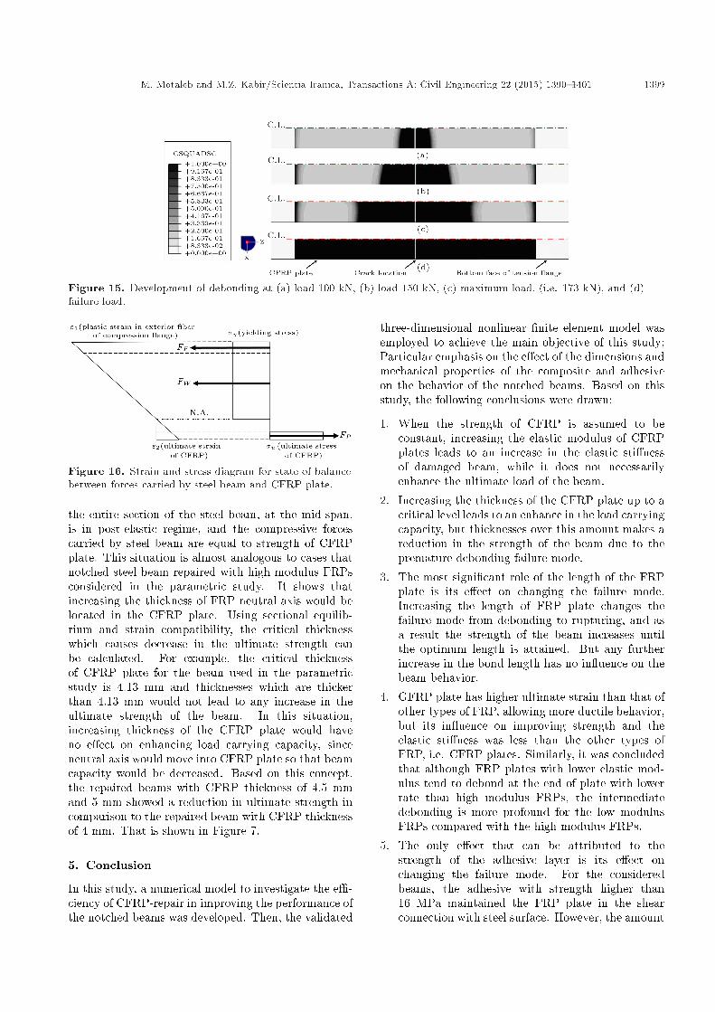
4.5. Extended studies4.5.1. Debonding behaviorTo have a clear insight into the bond failure mechanismof CFRP-repaired steel beams, the damage indicesin the bondline of three beams repaired using CFRPplates with elastic moduli 200 GPa, 400 GPa, and600 GPa against the distance from the end of CFRPplate are shown in Figure 13. Here, damage index refersto variables that indicate whether a certain damageinitiation criterion has been satis�ed or not, and a valueof 1.0 indicates that the damage initiation criterion hasbeen satis�ed. This study showed that in the caseof notched beams repaired with adhesively bondingCFRP plate, debonding is often initiated from notch,and as the opening of the mouth of notch is increased,the intermediate debonding propagates toward endsof CFRP plate. Meanwhile, with further increase inthe applied load, debonding is also initiated at theends of CFRP. Schematic damage propagation in steel-FRP interface including intermediate debonding andplate end debonding is shown in Figure 14. Thedebonded area is �nally completed at the areas closeto the plate ends, since debonding moves away fromthe plate ends with lower rate than that from thenotch. For example, in the case of repaired beam usingCFRP plate with elastic modulus equals to 200 GPa,the debonding development is shown in Figure 15(a)-(d) which demonstrate the debonded area from steel
Figure 13. Damage indices in steel-CFRP interface at(a) load 150 kN, and (b) failure load.
Figure 14. Schematic presentation of damagepropagation in CFRP-steel interface.
surface at loads 100 kN, 150 kN, 173 kN, and failure,respectively. These �gures clearly show that thedevelopment of debonding initiates in a region wherethe FRP is highly stressed and moves towards the plateends where the stress in the FRP plate is less. Lookingat Figure 13 in which the damage indices in CFRP-steel interface are plotted against the distance from theend of CFRP plates at the load of 150 kN and at thefailure load, respectively, it can be found out that inthe case of CFRPs with higher modulus of elasticity,there is a higher tendency towards debonding at theend of the CFRP plate while that is less in the vicinityof the crack, when it is compared to CFRP plateswith lower elasticity modulus. This phenomenon comesfrom this reality that the sti�er plate has greater abilityto control the mouth opening of the notch than it existsin normal modulus CFRP plates. This study showsthat FRPs with higher modulus have more potentialto be debonded at the end of plate while its tendency(to debonding) in the vicinity of the crack is less thanFRPs with lower modulus.
4.5.2. Rupturing behaviorFigure 16 shows a con�guration in which the sectionalforces are in equilibrium, where FF , FW and FP areforces carried by compression ange, steel web, andCFRP plate respectively. It shows a situation where
M. Motaleb and M.Z. Kabir/Scientia Iranica, Transactions A: Civil Engineering 22 (2015) 1390{1401 1399
Figure 15. Development of debonding at (a) load 100 kN, (b) load 150 kN, (c) maximum load, (i.e. 173 kN), and (d)failure load.
Figure 16. Strain and stress diagram for state of balancebetween forces carried by steel beam and CFRP plate.
the entire section of the steel beam, at the mid-span,is in post-elastic regime, and the compressive forcescarried by steel beam are equal to strength of CFRPplate. This situation is almost analogous to cases thatnotched steel beam repaired with high modulus FRPsconsidered in the parametric study. It shows thatincreasing the thickness of FRP neutral axis would belocated in the CFRP plate. Using sectional equilib-rium and strain compatibility, the critical thicknesswhich causes decrease in the ultimate strength canbe calculated. For example, the critical thicknessof CFRP plate for the beam used in the parametricstudy is 4.13 mm and thicknesses which are thickerthan 4.13 mm would not lead to any increase in theultimate strength of the beam. In this situation,increasing thickness of the CFRP plate would haveno e�ect on enhancing load carrying capacity, sinceneutral axis would move into CFRP plate so that beamcapacity would be decreased. Based on this concept,the repaired beams with CFRP thickness of 4.5 mmand 5 mm showed a reduction in ultimate strength incomparison to the repaired beam with CFRP thicknessof 4 mm. That is shown in Figure 7.
5. Conclusion
In this study, a numerical model to investigate the e�-ciency of CFRP-repair in improving the performance ofthe notched beams was developed. Then, the validated
three-dimensional nonlinear �nite element model wasemployed to achieve the main objective of this study;Particular emphasis on the e�ect of the dimensions andmechanical properties of the composite and adhesiveon the behavior of the notched beams. Based on thisstudy, the following conclusions were drawn:
1. When the strength of CFRP is assumed to beconstant, increasing the elastic modulus of CFRPplates leads to an increase in the elastic sti�nessof damaged beam, while it does not necessarilyenhance the ultimate load of the beam.
2. Increasing the thickness of the CFRP plate up to acritical level leads to an enhance in the load carryingcapacity, but thicknesses over this amount makes areduction in the strength of the beam due to thepremature debonding failure mode.
3. The most signi�cant role of the length of the FRPplate is its e�ect on changing the failure mode.Increasing the length of FRP plate changes thefailure mode from debonding to rupturing, and asa result the strength of the beam increases untilthe optimum length is attained. But any furtherincrease in the bond length has no in uence on thebeam behavior.
4. GFRP plate has higher ultimate strain than that ofother types of FRP, allowing more ductile behavior,but its in uence on improving strength and theelastic sti�ness was less than the other types ofFRP, i.e. CFRP plates. Similarly, it was concludedthat although FRP plates with lower elastic mod-ulus tend to debond at the end of plate with lowerrate than high modulus FRPs, the intermediatedebonding is more profound for the low modulusFRPs compared with the high modulus FRPs.
5. The only e�ect that can be attributed to thestrength of the adhesive layer is its e�ect onchanging the failure mode. For the consideredbeams, the adhesive with strength higher than16 MPa maintained the FRP plate in the shearconnection with steel surface. However, the amount
1400 M. Motaleb and M.Z. Kabir/Scientia Iranica, Transactions A: Civil Engineering 22 (2015) 1390{1401
of partial debonding in the vicinity of the notchvaried through changing the adhesive strength.
6. It was observed that more ductile steel beams intheir properties are likely to fail due to the damageprogression at the steel-FRP interface, while sti�ersteel beams tend to be failed by breakage in the�bers.
7. Partial debonding at the notch location has negli-gible e�ect on the beam behavior until it developsand covers the entire interface so that a suddenfall is occurred in the load carrying capacity. Thedebonding failure mainly depends on the bondingstrength and anchorage length. In the case thatHM-CFRP plate covered 66% of the span andattached to adhesive strength of16 MPa ensures theprevention of this mode of failure.
8. It was shown that the sti�er CFRP plates, usinghigher modulus FRPs, tend to fail by rupturingat ultimate load since all the capacity of FRP isexploited. However, it should be considered thatusing high modulus FRPs brings brittle behaviorto repaired beams.
References
1. Yu, Y., Chiew, S.P. and Lee, C.K. \Bond failure ofsteel beams strengthened with FRP laminates - Part2: Veri�cation", Composites: Part B, 42, pp. 1122-1134 (2011).
2. Kadhim, M.M.A. \E�ect of CFRP plate lengthstrengthening continuous steel beam", Constructionand Building Materials, 28, pp. 648-652 (2012).
3. Seleem, M.H., Sharaky, I.A. and Sallam, H.E.M. \Flex-ural behavior of steel beams strengthened by carbon�ber reinforced polymer plates - Three dimensional�nite element simulation", Materials and Design, 31,pp. 1317-1324 (2010).
4. Dawood, M., Sumner, E., Rizkalla, S. and Schnerch,D. \Strengthening steel bridges with new high modu-lus CFRP materials", in Third International Confer-ence on Bridge Maintenance, Safety and Management(IABMAS'06), Portugal (2006).
5. Fam, A., MacDougall, C. and Shaat, A. \Upgradingsteel-concrete composite girders and repair of damagedsteel beams using bonded CFRP laminates", Thin-Walled Structures, 47, pp. 1122-1135 (2009).
6. Haghani, R. and Al-Emrani, M. \A new designmodel for adhesive joints used to bond FRP lam-inates to steel beams - Part A: Background andTheory",Construction and Building Materials, 34, pp.486-493 (2012).
7. Harries, K.A., Richard, M.J. and Kim, Y.J. \Fatiguebehaviour of CFRP retro�tted damaged steel beams",
in Proceedings of 13th International Conference onStructural Faults and Repair, Edinburgh (2010).
8. Hmidan, A., Kim, Y.J. and Yazdani, S. \CFRP repairof steel beams with various initial crack con�gura-tions", Journal of Composites for Construction ASCE,15, pp. 952-962 (2011).
9. Howard, S.L. \Repair of notched steel beams usingultra-high modulus carbon �bre reinforced polymer",M.Sc. (Eng.) Thesis, Department of Civil Engineering,Queen's University, Kingston, Ont., Canada (2006).
10. Kim, Y.J. and Brunell, G. \Interaction betweenCFRP-repair and initial damage of wide- ange steelbeams subjected to three-point bending", CompositeStructures, 93, pp. 1986-1996 (2011).
11. Lingho�, D. and Al-Emrani, M. \Performance of steelbeams strengthened with CFRP laminate - Part 2: FEanalyses", Composites: Part B, 41, pp. 516-522 (2010).
12. Liu, X., Silva, P.F. and Nanni, A. \Rehabilitation ofsteel bridge members with FRP composite materials",in Proc., CCC 2001, Composites in Construction, pp.613-617, Porto, Portugal (2001).
13. Tavakkolizadeh, M. and Saadatmanesh, H. \Repairof damaged steel-concrete composite girders usingcarbon �ber-reinforced polymer sheets", Journal ofComposites for Construction ASCE, 7, pp. 311-322(2003).
14. Kumar, A.M. and Hakeem, S.A. \Optimum design ofsymmetric composite patch repair to centre crackedmetallic sheet", Comp. Struct., 49, pp. 285-292 (2000).
15. Liu, C.F., Jou, H.S. and Lee, Y.T. \Stress intensityfactor of a patched crack", Int. J. Solid Struct., 34,pp. 1557-1562 (1997).
16. Brighenti, R., Carpinteri, A. and Vantadori, S. \Agenetic algorithm applied to optimisation of patchrepairs for cracked plates", Int. J. of Solids andStructures, 44, pp. 466-475 (2006).
17. Tsai, G.C. and Shen, S.B. \Fatigue analysis ofcracked thick aluminium plate bonded with compositepatches", Compos. Struct., 64, pp. 79-90 (2004).
18. ABAQUS. ABAQUS/standard user's manual.ABAQUS Inc. (2010).
19. ACI, Building Code Requirements for Structural Con-crete (ACI 318-08) and Commentary (2008).
20. Hashin, Z. \Failure criteria for unidirectional �bercomposites", Journal of Applied Mechanics, 47, pp.329-334 (1980).
21. Davila, C.G., Camanho, P.P. and Rose, C.A. \Failurecriteria for FRP laminates", Journal of CompositeMaterials, 39, pp. 323-345 (2005).
22. Camanho, P.P. and Davila, C.G. \Mixed-mode decohe-sion �nite elements for the simulation of delaminationin composite materials", NASA/TM-2002-211737, pp.1-37 (2002).
23. Godat, A., Labossi�ere, P. and Neale, K.W. \Numer-
M. Motaleb and M.Z. Kabir/Scientia Iranica, Transactions A: Civil Engineering 22 (2015) 1390{1401 1401
ical investigation of the parameters in uencing thebehaviour of FRP shear-strengthened beams", Con-struction and Building Materials, 32, pp. 90-98 (2012).
Biographies
Mehdi Motaleb received his BS degree in CivilEngineering from Azad University, Tehran South andMS degree in Structural Engineering from AmirkabirUniversity of Technology, Tehran, Iran. He is currentlya PhD student at Saint Louis University, USA. Hisresearch interests are in the areas of bridges, com-posite materials, modeling, rehabilitation of structural
members using FRP materials, and structural healthmonitoring.
Mohammad Zaman Kabir is Professor and Chairof Civil and Environmental Engineering Departmentat Amirkabir University of Technology, Tehran, Iran.He received his BS and MS degrees from AmirkabirUniversity of Technology and his PhD degree fromWaterloo University in Canada. His research interestsinclude structural stability, structural analysis usingFEM, experimental methods in structural engineering,composite structures, structural optimization, damagedetection and rehabilitation of structures.