me3200 electronic instrumentation and measurement courseware
TRANSCRIPT

ME3200 Electronic Instrumentation and Measurement Courseware
Ready-to-Teach Package for Electronic Instrumentation and Measurement
Quick Start Guide revision 2.03
Printed on 20 September 2012

http://dreamcatcher.asia/cw [email protected]
ME3200 Electronic Instrumentation and Measurement
Quick Start Guide - 2/33
NOTE: This product has been tested and found to conform to the following EMC standards. The limits are designed to provide reasonable protection against harmful interference in a laboratory installation.
Standard Limit
EMC: IEC61326-1:2005 / EN61326-1:2006
CISPR11:2003/EN55011:2007
IEC 61000-4-3:2002 / EN 61000-4-3:2002
Class A, Group 1 3 V/m (80 MHz-1.0 GHz) 3 V/m (1.4 GHz-2.0 GHz) 1 V/m (2.0 GHz-2.7 GHz)
This product complies with the requirements of the Low Voltage Directive 73/23/EEC and EMC Directive 89/336/EEC, and carries the CE-marking. CAUTION – ESD! THIS PRODUCT CONTAINS ELECTRONIC COMPONENTS SENSITIVE TO ELECTROSTATIC DISCHARGE. An electrostatic discharge generated by a person or an object coming in contact with the electrical components may damage or destroy the product. To avoid the risk of electrostatic discharge, please observe the handling precautions and recommendations contained in the EN100015-1 standard. Do not connect or disconnect the device while it is being energized. WARNING: CHANGES OR MODIFICATIONS NOT EXPRESSLY APPROVED BY THE PARTY RESPONSIBLE FOR COMPLIANCE WITH THE EMC RULES COULD VOID THE USER’S AUTHORITY TO OPERATE THE PRODUCT.

http://dreamcatcher.asia/cw [email protected]
ME3200 Electronic Instrumentation and Measurement
Quick Start Guide - 3/33
Table of Contents Table of Contents .......................................................................................................................................... 3 1. Read Me First ............................................................................................................................................ 4 2. Courseware Overview ............................................................................................................................... 5 3. Courseware Configuration ........................................................................................................................ 6 4. Quick Setup and Verification ..................................................................................................................... 9 5. Support and Warranty ............................................................................................................................. 18 Appendix A: ME3200 Electronic Instrumentation Kit .................................................................................. 19 Appendix B: Specifications .......................................................................................................................... 20 Appendix C: Using Modular Instruments .................................................................................................... 21

http://dreamcatcher.asia/cw [email protected]
ME3200 Electronic Instrumentation and Measurement
Quick Start Guide - 4/33
1. Read Me First Congratulations on your purchase of the ME3200 Electronic Instrumentation and Measurement courseware! Please read this Quick Start Guide carefully to ensure you get the most out of your investment in this solution. This courseware includes the following items: Item Quantity Description
CD 1 o Teaching slides (Microsoft® PowerPoint format) o Lab sheets (Microsoft® Word format) o Problem-based assignments (Microsoft® Word format)
ME3200 Electronic Instrumentation Kit
1
The hardware kit consists of — Sensors: IR proximity sensor, light dependent resistor,
centigrade temperature sensor — Signal conditioning circuits: bridge, current amplifier,
non-inverting amplifier, voltage comparator — Digital Output circuits: D-type flip-flops/latches,
mechanical relay, buzzer — Others: Resonant circuit, analog-to-digital converter
Power supply cable 1 set 4 x banana-to-grabber clips
Jumper cables 6 Cable terminated with grabber clips at both ends
BNC cables 1 BNC(m)-to-grabber clip cable
1 BNC(f)-to-BNC(f) cable
Antistatic wrist strap 1 For ESD protection (required to wear when handling the device)
The following items are not included in this solution but are required/recommended:
One PC running Microsoft Windows 2000/XP/Vista® with a minimum of 512 MB RAM
Appropriate measurement instruments (see Section 3.5, "Lab Station" for details)
Appropriate Train-the-Trainer Program (see Section 3.6, "Train-the-Trainer Program" for details)
Complete the steps in Section 4, "Quick Setup and Verification" to start using the ME3200 Electronic Instrumentation Kit. Thank you for your purchase and do contact us (see Section 5, "Support and Warranty") if you require any assistance.
IMPORTANT The ME3200 Electronic Instrumentation kit can be damaged by excessive power levels from the
instruments. Please adhere strictly to the power levels recommended in the instructions.

http://dreamcatcher.asia/cw [email protected]
ME3200 Electronic Instrumentation and Measurement
Quick Start Guide - 5/33
2. Courseware Overview The ME3200 is a ready-to-teach package targeting 1st or 2nd year undergraduates. This solution focuses on electronic instrumentation and measurement techniques. To achieve a better understanding on the subject, students are required to complete the lab exercises and assignments using Agilent basic instruments such as the 34405A digital multimeter, the E3631A power supply, the 33220A function generator, and the DSO1002A oscilloscope. The training kit consists of sensors, signal conditioning circuits, digital output circuits, and resonance circuit, which allow students to explore the functionalities and applications of typical end-to-end measurement systems. This courseware consists of:
Teaching slides (editable with Microsoft PowerPoint)
Training kit: Electronic Instrumentation Kit
Lab sheets (editable with Microsoft Word)
Problem-based assignments (editable with Microsoft Word)
Model answers and solutions (downloadable by registered instructors) The following items are not included but recommended:
Agilent Technologies 34405A 5½ Digit Multimeter
Agilent Technologies DSO1002A 60 MHz Oscilloscope
Agilent Technologies 33220A Function Generator
Agilent Technologies E3631A Triple Output DC Power Supply
Train-the-Trainer Program This complete solution is designed to impart knowledge in:
Measurement principles
End-to-end measurement system
Introduction to measurement instruments
Usage of instrument programming tools
Usage of basic instruments
Figure 1 – ME3200 Training Kit and Recommended Instruments

http://dreamcatcher.asia/cw [email protected]
ME3200 Electronic Instrumentation and Measurement
Quick Start Guide - 6/33
3. Courseware Configuration 3.1 Teaching Slides
Editable slides in Microsoft PowerPoint format are provided for the following topics:
Digital Multimeter*
DC Power Supply*
Function Generator*
Digital Oscilloscope*
Basic Principles of Measurement
Measurement of Electrical Quantities
Quality of Measurement
Sensors and Transducers
Analog Signal Conditioning
Electronic Measurement Instruments
Introduction to Instrument Systems
The Basics of Instrument Programming Using VEE
* For Induction Program 3.2 ME3200 Electronic Instrumentation Kit
Sensors o IR proximity sensor o Light dependent resistor o Centigrade temperature sensor
Signal conditioning circuits o Bridge o Current amplifier o Non-inverting amplifier o Voltage comparator
Digital Output circuits o D-type flip-flops/latches o Mechanical relay o Buzzer
Others o Resonant circuit o Analog-to-digital converter

http://dreamcatcher.asia/cw [email protected]
ME3200 Electronic Instrumentation and Measurement
Quick Start Guide - 7/33
3.3 Lab Sheets
No Lab Sheet Objective Duration
1 Measurement of Voltage and Current
To perform basic measurement of voltage and current
3 Hours
2 Measurement of Time-Dependent Signals
To study and measure time-dependent signals
3 Hours
3 Quality of Measurement 1 To study quality measurement parameters
3 Hours
4 Quality of Measurement 2 To study quality measurement parameters
3 Hours
5 Analog Signal Conditioning To understand the basic operation of analog signal conditioning circuits
3 Hours
6 Measurement of Digital Signals To study and measure digital signals 3 Hours
7 Introduction to Data Flow Programming[1]
To understand the basics of data flow programming using VEE
3 Hours
8 Measurement Automation[1] To perform measurement automation using VEE
3 Hours
[1] Agilent VEE is required for this lab. 3.4 Problem-based Assignments No Assignment 1 Case Study on Dynamometry 2 Motor Current and Speed-Torque Characteristics 3.5 Lab Station
Basic Setup
1 x Agilent 34405A 5½ Digit Multimeter
1 x Agilent DSO1002A 60 MHz Oscilloscope
1 x Agilent 33220A Function Generator
1 x Agilent E3631A Triple Output DC Power Supply
The above instruments are recommended, but may be replaced by other models with equivalent performance.

http://dreamcatcher.asia/cw [email protected]
ME3200 Electronic Instrumentation and Measurement
Quick Start Guide - 8/33
The following table shows the training kit and recommended instruments used in each lab.
Training Kit Required Instrument(s)
ME3200 Electronic Instrumentation Kit
Option 1 Option 2 Option 3
Power Supply & Multimeter
Power Supply, Function Generator,
& Oscilloscope
Power Supply, Function Generator, Multimeter, &
Oscilloscope Lab 1 Lab 2 Lab 3 Lab 4 Lab 5 Lab 6 Lab 7 Lab 8 3.6 Train-the-Trainer Program (recommended, not included in courseware) Lectures
Electronic Instrumentation – Part 1
Electronic Instrumentation – Part 2
Selected topics from the courseware teaching material
Lab Exercises
Selected exercises from the lab sheets
Training details are available at http://dreamcatcher.asia/

http://dreamcatcher.asia/cw [email protected]
ME3200 Electronic Instrumentation and Measurement
Quick Start Guide - 9/33
4. Quick Setup and Verification The following steps demonstrate the basic setup and lab test of the ME3200 Electronic Instrumentation Kit:
— Power on the ME3200 Electronic Instrumentation Kit
— IR Proximity Sensor Test and Verification
— Light Dependent Resistor Test and Verification
— Centigrade Temperature Sensor Test and Verification
— Resonant Circuit Test and Verification
4.1 Power on the ME3200 Electronic Instrumentation Kit
1. The ME3200 Electronic Instrumentation Kit requires two power supplies (+5 V and +9 V) in order to operate.
2. Turn on the power supply unit. Set the dual channel output voltages to exactly +5 V and +9 V, respectively. Set both current limits to 1.0 A.
3. Next, connect the power supply to the ME3200 Electronic Instrumentation Kit as shown in Figure 2.
Figure 2 – Connections Between the Power Supply and the ME3200 Electronic Instrumentation Kit
4. Connect the +9 V power supply output to test point TP1 and GND to TP3 of the ME3200 Electronic Instrumentation Kit (at the top left-hand corner of the board).
5. Connect the +5 V power supply output to test point TP2 and GND to TP3 of the ME3200 Electronic Instrumentation Kit respectively.
6. Make sure that the polarities of the terminals are correctly connected. Refer to

http://dreamcatcher.asia/cw [email protected]
ME3200 Electronic Instrumentation and Measurement
Quick Start Guide - 10/33
Table 1 to verify your connections.

http://dreamcatcher.asia/cw [email protected]
ME3200 Electronic Instrumentation and Measurement
Quick Start Guide - 11/33
Table 1 – Connection Between the Power Supply and the ME3200 Electronic Instrumentation Kit
ME3200 Electronic Instrumentation Kit Power Supply Unit
+9 V Terminal, TP1 +9V Terminal
GND Terminal, TP3 GND Terminal
+5 V Terminal, TP2 +5 Terminal
GND Terminal, TP3 GND Terminal
7. Enable the power supply outputs and the annunciators at the front panel should be turned on (providing a constant voltage supply).
8. If the CC annunciator is on, disable the power supply output by pressing the Output On/Off button. Check if this is due to current limit setting or a faulty connection.
Caution: The ME3200 Electronic Instrumentation Kit does not contain an on-board voltage regulation circuit. DO NOT OVER SUPPLY the maximum required voltages to the ME3200 Electronic Instrumentation Kit as this might damage the components on the board.
9. The red LED D9 on the Relay Circuit will be turned on if +5 V is correctly supplied to the ME3200 Electronic Instrumentation Kit.
10. Adjust the potentiometer VR1 on the Light Dependent Resistor module; this will vary the brightness of the white LED D10 if +9 V is correctly supplied.
11. Turn off the ME3200 Electronic Instrumentation Kit by disabling the power supply output. 4.2 IR Proximity Sensor Test and Verification
1. The IR Proximity Sensor Test will be carried out using three modules on the ME3200 Electronic Instrumentation Kit. These modules are the IR Proximity Sensor, the Voltage Comparator, and the Relay Circuit.
2. Maintain the same connections between the ME3200 Electronic Instrumentation Kit and power supply as prepared in Section 4.1
3. Connect the IR Proximity Sensor, the Voltage Comparator, and the Relay Circuit as shown in Figure 3.
4. See Table 2 to verify your connections.
Table 2 – Circuit Connections for the IR Proximity Sensor Test
From To
OUT1 terminal, TP5 of the IR Proximity Sensor IN9 terminal, TP38 of the Voltage Comparator
OUT10 terminal, TP41 of the Voltage Comparator IN10 terminal, TP43 of the Relay Circuit
5. Turn on the ME3200 Electronic Instrumentation Kit by enable the power supply output.

http://dreamcatcher.asia/cw [email protected]
ME3200 Electronic Instrumentation and Measurement
Quick Start Guide - 12/33
Figure 3 – Circuit Connections for the IR Proximity Sensor Test
6. The red LED D8 on the Relay Circuit will be turned on if the connections are correct. The relay circuit is in the normally opened condition at the beginning.
7. Turn the variable resistor VR3 in the clockwise direction until it stops. This will set the inverting input voltage (V–) of the voltage comparator to 5 V.
8. Use a piece of white paper as an obstacle and place it in front of the IR proximity sensor. Slowly decrease the distance between the paper and the sensor by moving the paper towards the sensor.
9. When the distance between the obstacle and the sensor reaches about 2 cm to 3 cm, the relay circuit will be triggered to close normally and the LED D9 will be turned on.
10. This test can be considered successful if the results as discussed in the previous steps can be obtained. Verify your connections if you fail to obtain the desired results.
11. Turn off the ME3200 Electronic Instrumentation Kit by disabling the power supply output. 4.3 Light Dependent Resistor Test and Verification
1. The Light Dependent Resistor Test will be carried out using four modules on the ME3200 Electronic Instrumentation Kit. These modules are the Light Dependent Resistor, the Bridge Current Amplifier, the Voltage Comparator, and the Buzzer Circuit.
2. Maintain the same connections between the ME3200 Electronic Instrumentation Kit and power supply as prepared in Section 4.1.
3. Connect the Light Dependent Resistor, the Bridge Current Amplifier, the Voltage Comparator, and the Buzzer Circuit as shown in Figure 4.

http://dreamcatcher.asia/cw [email protected]
ME3200 Electronic Instrumentation and Measurement
Quick Start Guide - 13/33
Figure 4 – Circuit Connections for the Light Dependent Resistor Test
4. See Table 3 to verify your connections.
Table 3 – Circuit Connections for Light Dependent Resistor Test
From To
OUT2 terminal, TP10 of the Light Dependent Resistor IN5 terminal, TP22 of the Bridge Current Amplifier
OUT4 terminal, TP12 of the Light Dependent Resistor IN6 terminal, TP23 of the Bridge Current Amplifier
OUT8 terminal, TP25 of the Bridge Current Amplifier IN9 terminal, TP38 of the Voltage Comparator
OUT10 terminal, TP41 of the Voltage Comparator IN11 terminal, TP47 of the Buzzer Circuit
5. Turn on the ME3200 Electronic Instrumentation Kit by enable the power supply output.
6. The red LED D9 on the Relay Circuit will be turned on if the connections are correct.
7. Turn the variable resistor VR1 in order to adjust the brightness of the white LED D10 (the clockwise direction to increase and the counter-clockwise direction to decrease). The resistance of the light dependent resistor, LDR1 will be varied according to the intensity of light that strikes on it.
8. Measure the voltage at terminal TP50 on the bridge current amplifier. This is the non-inverting input voltage of the bridge current amplifier. The measured voltage should in the range of 2.55 V (when D10 is Off) to 2.48 V (when D10 is On).
9. Next, test the functionality of the buzzer circuit by adjusting the variable resistor VR1. Fully turn the VR1 in the clockwise direction in order to set the brightness of the white LED D10 to maximum.
10. The buzzer is turned off when the brightness of LED D10 is set to maximum. Slowly reduce the brightness of the LED until it is turned off. When the brightness of the LED is reduced to a certain level, the buzzer circuit will be turned on and you should be able to hear a long beep produced by the buzzer.
12. This test can be considered successful if the results as discussed in previous steps can be obtained. Verify your connections if you fail to obtain the desired results.
13. Turn off the ME3200 Electronic Instrumentation Kit by disabling the power supply output.

http://dreamcatcher.asia/cw [email protected]
ME3200 Electronic Instrumentation and Measurement
Quick Start Guide - 14/33
4.4 Centigrade Temperature Sensor Test and Verification
1. The Centigrade Temperature Sensor Test will be carried out using four modules on the ME3200 Electronic Instrumentation Kit. These modules are the Centigrade Temperature Sensor, the Gain Amplifier, the Analog-To-Digital Converter, and the Buzzer Circuit.
2. Maintain the same connections between the ME3200 Electronic Instrumentation Kit and power supply as prepared in Section 4.1.
3. Connect the Centigrade Temperature Sensor, the Gain Amplifier, Analog-To-Digital Converter and the Buzzer Circuit as shown in Figure 5.
Figure 5 – Circuit Connections for the Centigrade Temperature Sensor Test
4. Refer to Table 4 to verify your connections.
Table 4 – Circuit Connections for Centigrade Temperature Sensor Test
From To
OUT5 terminal, TP15 of the Centigrade Temperature Sensor
IN7 terminal, TP28 of the Gain Amplifier
OUT9 terminal, TP31 of the Gain Amplifier
IN8 terminal, TP33 of the Analog-To-Digital Converter
5. Connect all jumpers from J20 to J27 as shown in Figure 5 if they are not yet connected.
6. Connect the jumper on J28 to position 2 and 3 as shown in Figure 6.
Figure 6 – Position of the Jumper on J28
http://dreamcatcher.asia/cw [email protected]
ME3200 Electronic Instrumentation and Measurement
Quick Start Guide - 15/33
7. Turn on the ME3200 Electronic Instrumentation Kit by enable the power supply output.
8. The red LED D9 on the Relay Circuit will be turned on if the connections are correct.
9. Turn the variable resistor VR2 in order to vary the gain of the amplifier (the counter-clockwise direction to increase and the clockwise direction to decrease). Set the resistance of VR2 to 40 kΩ. You may measure the resistance through TP27 and TP30. This will allow the analog output voltage from the temperature sensor to be scaled to five times larger than the original magnitude.
10. Measure the voltage at terminal OUT5, TP15 on the centigrade temperature sensor using a digital multimeter. The measured voltage should be in mV, which is the output of the temperature sensor LM35. The sensitivity of the temperature sensor LM35 is 10 mV per degree Celsius. The
room temperature sensed by the sensor ismV
VoltageMeasured
10.
11. The gain ratio of the gain amplifier is about 5. Next, measure the voltage at terminal OUT9, TP31 on the gain amplifier. The measured voltage should be amplified about five times compared to the voltage measured in step 10.
12. The 8-bit analog-to-digital converter (ADC) on the ME3200 Electronic Instrumentation Kit takes the analog output from the temperature sensor and turns it into a binary number. Thus, each binary number from the ADC represents a certain voltage level. The resolution of the 8-bit ADC is 256. The red LEDs D0 and D7 are the LSB and MSB for the output of the ADC respectively. Observe the condition of the red LEDs from D0 to D7. They represent the digital output of the temperature sensor.
13. Resistors R6 and R7, which are installed under the DC Axial Fan with the LM35 temperature sensor, are used as the heating source in the circuit.
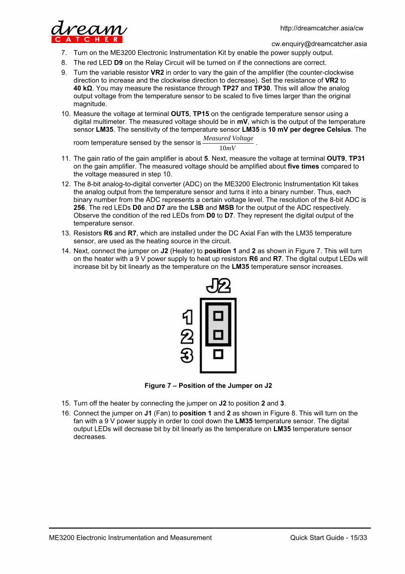
14. Next, connect the jumper on J2 (Heater) to position 1 and 2 as shown in Figure 7. This will turn on the heater with a 9 V power supply to heat up resistors R6 and R7. The digital output LEDs will increase bit by bit linearly as the temperature on the LM35 temperature sensor increases.
Figure 7 – Position of the Jumper on J2
15. Turn off the heater by connecting the jumper on J2 to position 2 and 3.
16. Connect the jumper on J1 (Fan) to position 1 and 2 as shown in Figure 8. This will turn on the fan with a 9 V power supply in order to cool down the LM35 temperature sensor. The digital output LEDs will decrease bit by bit linearly as the temperature on LM35 temperature sensor decreases.

http://dreamcatcher.asia/cw [email protected]
ME3200 Electronic Instrumentation and Measurement
Quick Start Guide - 16/33
Figure 8 – Position of the Jumper on J1
17. Turn off the fan by connecting the jumper on J1 to position 2 and 3.
18. This test can be considered successful if the results as discussed in the previous steps can be obtained. Verify your connections if you fail to obtain the desired results.
19. Turn off the ME3200 Electronic Instrumentation Kit by disabling the power supply output. 4.5 Resonant Circuit Test and Verification
1. The Resonant Circuit Test will be carried out using one module on the ME3200 Electronic Instrumentation Kit. This module is the Resonant Circuit.
2. No power supply is required under this test. You may disconnect the power supply on TP1, TP2, and TP3. Only the function generator and the oscilloscope are used in this test.
3. The resonant circuit is able to be a low pass filter (LPF) or a high pass filter (HPF) according to the connections of the jumpers on J4 to J19. Figure 9 shows the resonant circuit module on the ME3200 Electronic Instrumentation Kit.
Figure 9 – Resonant Circuit Module

http://dreamcatcher.asia/cw [email protected]
ME3200 Electronic Instrumentation and Measurement
Quick Start Guide - 17/33
4. Four types of filter can be constructed based on the connections of jumpers. This is shown in Table 5.
Table 5 – Configurations of Jumpers on the Resonant Circuit
Type of Filter Connection of Jumper
RC Low Pass Filter (LPF) Connect jumpers on J6, J9, J11, J14, J17, and J19
RC High Pass Filter (HPF) Connect jumpers on J5, J8, J12, J15, J17, and J19
RL Low Pass Filter (LPF) Connect jumpers on J4, J7, J12, J15, J17, and J19
RL High Pass Filter (HPF) Connect jumpers on J6, J9, J10, J13, J17, and J19
4.5.1 RC Low Pass Filter
1. Complete the connections for the resonant circuit as shown in Figure 10.
Figure 10 – RC Low Pass Filter
2. Connect the red probe and black probe of the function generator to IN3 terminal (TP17) and IN4 terminal (TP18) respectively.
3. Connect six jumpers on J6, J9, J11, J14, J17, and J19 to form an RC low pass filter. Verify your connections by referring to Table 5. Leave the other jumpers disconnected.
4. Next, turn on the function generator and generate a pure sine wave with the amplitude of 5 V and frequency of 500 Hz.
5. The signal from the IN3 terminal (TP17) is the input signal to the RC low pass filter, while the signal from the OUT6 terminal (TP19) is the output signal of RC low pass filter.
6. Use an oscilloscope to observe the signal from the IN3 terminal (TP17) and the OUT6 terminal (TP19). The signal on both channels should be exactly the same because the signal is still within the low pass region.
7. The resistance and capacitance of R8 and C2 are 100 Ω and 0.1 µF respectively; they are used to set the cut-off frequency of the low pass filter at 15.923 kHz. Disable the output of the function generator.
8. Set the function generator to the Linear Sweep mode. Set the start and stop frequencies to 20 Hz and 20 kHz. Enable the output of the function generator.
9. You should be able to observe that the amplitude of the output signal on the oscilloscope is attenuated when the frequency is increased beyond the cut-off frequency. Signals higher than the cut-off frequency will be filtered out. Disable the output of function generator.

http://dreamcatcher.asia/cw [email protected]
ME3200 Electronic Instrumentation and Measurement
Quick Start Guide - 18/33
4.5.2 RC High Pass Filter
1. Complete the connections for the resonant circuit as shown in Figure 11.
Figure 11 – RC High Pass Filter
2. Connect the red probe and black probe of function generator to the IN3 terminal (TP17) and the IN4 terminal (TP18) respectively.
3. Connect six jumpers on J5, J8, J12, J15, J17, and J19 to form an RC high pass filter. Verify your connections by referring to Table 5. Leave the other jumpers disconnected.
4. Next, turn on the function generator and generate a pure sine wave with the amplitude of 5 V and frequency of 500 Hz.
5. The signal from the IN3 terminal (TP17) is the input signal to the RC high pass filter, while the signal from the OUT6 terminal (TP19) is the output signal of RC high pass filter.
6. Use an oscilloscope to observe the signal from the IN3 terminal (TP17) and the OUT6 terminal (TP19). The signal on both channels should be exactly the same because the signal is still within the high pass region.
7. The resistance and capacitance of R9 and C1 are 470 Ω and 1 µF respectively; they are used to set the cut-off frequency of the high pass filter as 338 Hz. Disable the output of the function generator.
8. Set the function generator to the Linear Sweep mode. Set the start and stop frequencies to 20 Hz and 20 kHz. Enable the output of the function generator.
9. You should be able to observe that the amplitude of the output signal on the oscilloscope is attenuated when the frequency is decreased beyond the cut-off frequency. Signals lower than the cut-off frequency will be filtered out. Disable the output of function generator.

http://dreamcatcher.asia/cw [email protected]
ME3200 Electronic Instrumentation and Measurement
Quick Start Guide - 19/33
5. Support and Warranty 5.1 Terms and Conditions This courseware product contains scholarly and technical information and is protected by copyright laws and international treaties. No part of this publication may be reproduced by any means, be it transmitted, transcribed, photocopied, stored in a retrieval system, or translated into any language in any form, without the prior written permission of Acehub Vista Sdn. Bhd. The use of the courseware product and all other products developed and/or distributed by Acehub Vista Sdn. Bhd. are subject to the applicable License Agreement.
For further information, see the Courseware Product License Agreement.
To retrieve the password for installation of the provided materials and software as well as the model answers and solutions for lab sheets, please register yourself at http://dreamcatcher.asia/cw under the Product Registration menu using the product key provided with the teaching courseware. 5.2 Product Warranty
Acehub Vista Sdn. Bhd. warrants that its products sold will at the time of shipment be free from defects in material and workmanship and will conform to Acehub Vista Sdn. Bhd.'s applicable specifications.
If Acehub Vista Sdn. Bhd. receives notice of a defect or non-conformance during the one year warranty period, Acehub Vista Sdn. Bhd. will, at its option, repair or replace the affected product. Buyer will pay shipping expenses for return of such product to Acehub Vista Sdn. Bhd. or its authorized reseller. Acehub Vista Sdn. Bhd. or its authorized reseller will pay expenses for shipment of the repaired or replacement product.
This warranty shall not apply to any products Acehub Vista Sdn. Bhd. determines have been, by Buyer or otherwise, subject to operating and/or environmental conditions in excess of the maximum values established in applicable specifications, or have been subject to mishandling, misuse, neglect, improper testing, repair, alteration, damage, assembly, or processing that alters physical or electrical properties.
In no event will Acehub Vista Sdn. Bhd. be liable for any incidental or consequential damages.
This warranty extends to Buyer only and not to Buyer's customers or users of Buyer's products and is in lieu of all other warranties whether expressed, implied, or statutory including implied warranties of merchantability of fitness.
For technical support and warranty, e-mail [email protected]

http://dreamcatcher.asia/cw [email protected]
ME3200 Electronic Instrumentation and Measurement
Quick Start Guide - 20/33
Appendix A: ME3200 Electronic Instrumentation Kit As shown in Figure 12, the hardware kit consists of the following:
— Sensors: IR proximity sensor, light dependent resistor, centigrade temperature sensor — Signal conditioning circuits: bridge, current amplifier, non-inverting amplifier, voltage comparator — Digital Output circuits: D-type flip-flops/latches, mechanical relay, buzzer — Others: Resonant circuit, analog-to-digital converter
Figure 12 – ME3200 Electronic Instrumentation Kit
http://dreamcatcher.asia/cw [email protected]
ME3200 Electronic Instrumentation and Measurement
Quick Start Guide - 21/33
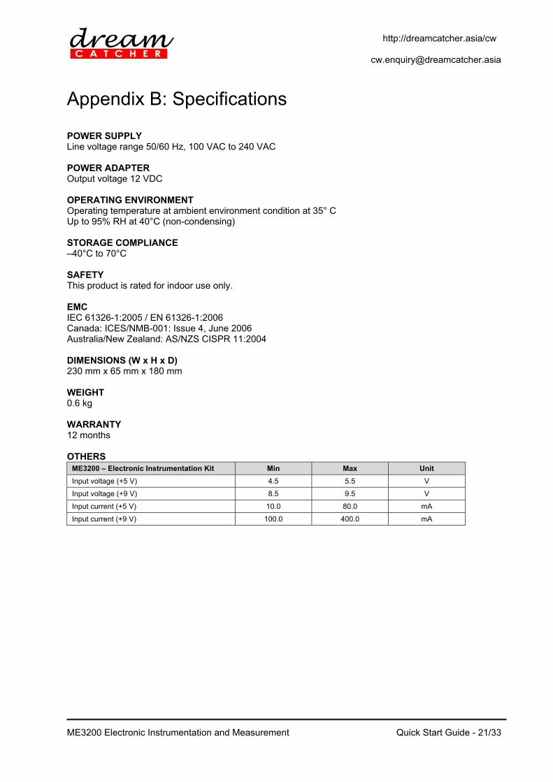
Appendix B: Specifications POWER SUPPLY Line voltage range 50/60 Hz, 100 VAC to 240 VAC POWER ADAPTER Output voltage 12 VDC OPERATING ENVIRONMENT Operating temperature at ambient environment condition at 35° C Up to 95% RH at 40°C (non-condensing) STORAGE COMPLIANCE –40°C to 70°C SAFETY This product is rated for indoor use only. EMC IEC 61326-1:2005 / EN 61326-1:2006 Canada: ICES/NMB-001: Issue 4, June 2006 Australia/New Zealand: AS/NZS CISPR 11:2004 DIMENSIONS (W x H x D) 230 mm x 65 mm x 180 mm WEIGHT 0.6 kg WARRANTY 12 months OTHERS
ME3200 – Electronic Instrumentation Kit Min Max Unit
Input voltage (+5 V) 4.5 5.5 V
Input voltage (+9 V) 8.5 9.5 V
Input current (+5 V) 10.0 80.0 mA
Input current (+9 V) 100.0 400.0 mA
http://dreamcatcher.asia/cw [email protected]
ME3200 Electronic Instrumentation and Measurement
Quick Start Guide - 22/33
Appendix C: Using Modular Instruments
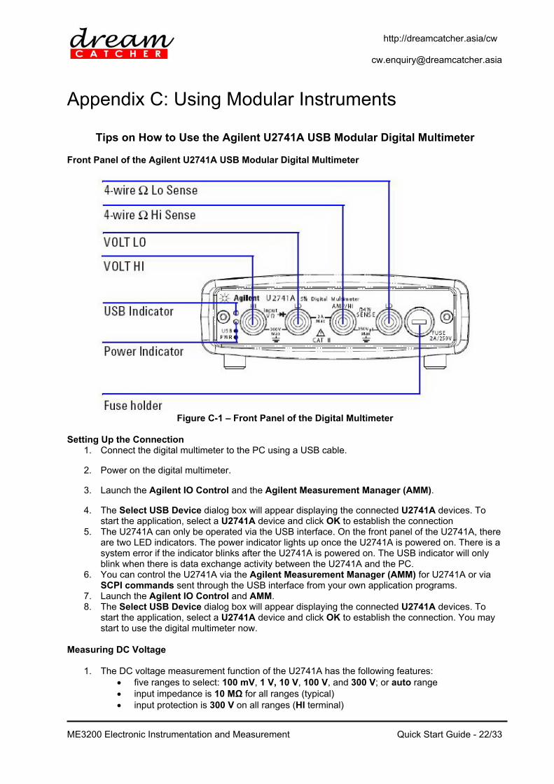
Tips on How to Use the Agilent U2741A USB Modular Digital Multimeter Front Panel of the Agilent U2741A USB Modular Digital Multimeter
Figure C-1 – Front Panel of the Digital Multimeter
Setting Up the Connection
1. Connect the digital multimeter to the PC using a USB cable.
2. Power on the digital multimeter.
3. Launch the Agilent IO Control and the Agilent Measurement Manager (AMM).
4. The Select USB Device dialog box will appear displaying the connected U2741A devices. To start the application, select a U2741A device and click OK to establish the connection
5. The U2741A can only be operated via the USB interface. On the front panel of the U2741A, there are two LED indicators. The power indicator lights up once the U2741A is powered on. There is a system error if the indicator blinks after the U2741A is powered on. The USB indicator will only blink when there is data exchange activity between the U2741A and the PC.
6. You can control the U2741A via the Agilent Measurement Manager (AMM) for U2741A or via SCPI commands sent through the USB interface from your own application programs.
7. Launch the Agilent IO Control and AMM. 8. The Select USB Device dialog box will appear displaying the connected U2741A devices. To
start the application, select a U2741A device and click OK to establish the connection. You may start to use the digital multimeter now.
Measuring DC Voltage
1. The DC voltage measurement function of the U2741A has the following features: five ranges to select: 100 mV, 1 V, 10 V, 100 V, and 300 V; or auto range input impedance is 10 MΩ for all ranges (typical) input protection is 300 V on all ranges (HI terminal)

http://dreamcatcher.asia/cw [email protected]
ME3200 Electronic Instrumentation and Measurement
Quick Start Guide - 23/33
2. Make the connection as shown in Figure B-2 in order to measure DC voltage. You can control the U2741A via the Agilent Measurement Manager (AMM) software for U2741A or via SCPI commands sent through the USB interface from your own application programs.
Figure C-2 – Measuring DC Voltage
3. If you are using the AMM, select the DCV function located at the top-left corner. Set the desired range under Range section. A suitable range should be selected to give the best measurement resolution. The reading is displayed and updated continuously.
4. If you are using SCPI commands, enter MEASure[:VOLTage]:DC? in order to make a DC voltage measurement.
Measuring DC Current
1. The DC current measurement function of the U2741A has the following features: three ranges to select: 10 mA, 100 mA, 1 A, and 2 A; or auto range input impedance is 10 MΩ for all ranges (typical) input protection fuse is 2 A, voltage rating 250 V on all ranges
2. Make the connection as shown in Figure in order to measure DC current. You can control the U2741A via the Agilent Measurement Manager (AMM) software for U2741A or via SCPI commands sent through the USB interface from your own application programs.
Figure C-3 – Measuring DC Current
3. If you are using the AMM, select the DCI function located at the top-left corner. Set the desired range under the Range section. A suitable range should be selected to give the best measurement resolution. The reading is displayed and updated continuously.
4. If you are using SCPI commands, enter MEASure:CURRent[:DC]? in order to make a DC current measurement.

http://dreamcatcher.asia/cw [email protected]
ME3200 Electronic Instrumentation and Measurement
Quick Start Guide - 24/33
Tips on How to Use the Agilent U2761A USB Modular Function Generator Front Panel of the Agilent U2761A USB Modular Function Generator
Figure A-1 – Front Panel of the U2761A Setup Connection
9. Connect the function generator to the PC using a USB cable. 10. Power on the function generator. 11. Launch the Agilent IO Control and the Agilent Measurement Manager (AMM). 12. The Select USB Device dialog box will appear displaying the connected U2761A devices. To
start the application, select a U2761A device and click OK to establish the connection. 13. Click Output to enable or disable the output of the function generator after the desired
parameters are set. 14. The U2761A is able to output five standard waveforms that are Sine, Square, Ramp, Triangle,
Pulse, and DC. 15. You can select one of the three built-in Arbitrary waveforms or create your own custom
waveforms. 16. You can also internally modulate Sine, Square, Ramp, Triangle, and Arbitrary waveforms using
AM, FM, PM, FSK, PSK, or ASK. 17. The linear or logarithmic frequency sweeping is available for Sine, Square, Ramp, Triangle, and
Arbitrary waveforms. 18. Table A- shows which output functions are allowed with modulation and sweep. 19. Each √ indicates a valid combination. If you change to a function that is not applicable for
modulation, or sweep; then the modulation or mode will be disabled.
Table A-1 – Output Functions
Sine Square Ramp Triangle Pulse DC Arbitrary
AM, FM, PM, FSK, PSK, ASK Carrier √ √ √ √ √
AM, FM, PM Internal Modulation √ √ √ √ √
FSK, PSK, ASK Internal Modulation √
Sweep Mode √ √ √ √ √

http://dreamcatcher.asia/cw [email protected]
ME3200 Electronic Instrumentation and Measurement
Quick Start Guide - 25/33
Agilent Measurement Manager Soft Front Panel (Function Generator)
Figure A-2 – Graphic User Interface of the Agilent Measurement Manager (Function Generator)
Figure A-2 shows the graphic user interface of the Agilent Modular Function Generator under the Agilent Measurement Manager (AMM). Table A- shows the features of each panel of the interface.
Table A-2 – Features of the AMM Function Generator Interface
No. Panel Features
1 Waveform Pattern Selection Select various types of output function by clicking the buttons.
2 Waveform Parameters Configure the function parameters (Frequency, Amplitude, and Offset)
3 Waveform Pattern Display Display a graph representation of the output function
4 Modes of Waveform Configure to modulation mode or sweep mode
5 Status Display Display the parameters and status of the configured output waveform
6 Trigger & Output Enable/Disable Enable/disable the Trigger and Output buttons (they are highlighted when enabled and grey when disabled)

http://dreamcatcher.asia/cw [email protected]
ME3200 Electronic Instrumentation and Measurement
Quick Start Guide - 26/33
Function Limitation If you change to a function where the maximum frequency is less than the current function, the frequency will be adjusted to the maximum value for the new function. For example, if you are currently outputting a 20 MHz sine wave and then change to the Ramp function, the U2761A will automatically adjust the output frequency to 200 kHz (the upper limit for Ramp). As shown in Table A-, the output frequency range depends on the function currently selected. The default frequency is 1 kHz for all functions.
Table A-3 – Output Frequency Range
Function Minimum Frequency Maximum Frequency
Sine 1 µHz 20 MHz Square 1 µHz 20 MHz Ramp, Triangle 1 µHz 200 MHz Pulse 500 µHz 5 MHz DC Not applicable Not applicable
Arbitrary 1 µHz 200 kHz 2 MHz (U2761A Option 801)
Amplitude Limitation The default amplitude is 1 Vpp (into 50 Ω) for all functions. If you change to a function where the maximum amplitude is less than the current function, the amplitude will automatically adjust to the maximum value for the new function. This may occur when the output units are Vrms or dBm due to the differences in crest factor for the various output functions. For example, if you output a 2.5 Vrms Square wave (into 50 Ω) and then change to the Sine wave function, the U2761A will automatically be adjusted the output amplitude to 1.768 Vrms (the upper limit for Sine wave in Vrms). Duty Cycle Limitations For Square waveforms, the U2761A may not be able to use the full range of duty cycle values at higher frequencies as shown below:
20% to 80% (frequency 10 MHz) 40% to 60% (frequency 10 MHz)
If you change to a frequency that cannot produce the current duty cycle, the duty cycle is automatically adjusted to the maximum value for the new frequency. For example, if you currently have the duty cycle set to 70% and then change the frequency to 12 MHz, the U2761A will automatically adjusts the duty cycle to 60% (the upper limit for this frequency). Output Termination This configuration applies to output amplitude and offset voltage only. The U2761A has a fixed series output impedance of 50 Ω to the dev ice output connector. If the actual load impedance is different from the specified value, the amplitude and offset levels will be incorrect.
The range of the output termination is 1 Ω to 10 kΩ, or Infinite. The default value is 50 Ω. The output termination setting is stored in volatile memory and upon power-off or after a remote
interface reset, the setting will return to a default value. If you specify a 50 Ω termination but are actually terminating into an open circuit, the actual
output will be twice the value specified. For example, if you set the offset to 100 mVDC (and specify a 50 Ω load) but are terminating the output into an open circuit, the actual offset will be 200 mVDC.
If you change the output termination setting, the output amplitude and offset levels are automatically adjusted (no error will be generated). For example, if you set the amplitude to 5 Vpp and then change the output termination from 50 Ω to high impedance, the amplitude value will

http://dreamcatcher.asia/cw [email protected]
ME3200 Electronic Instrumentation and Measurement
Quick Start Guide - 27/33
double to 10 Vpp. If you change from high impedance to 50 Ω, the displayed amplitude value will drop to half.
You cannot specify the output amplitude in dBm if the output termination is currently set to high impedance. The units are automatically converted to Vpp.
You may configure the output termination by clicking Tools in the menu bar. Select Waveform Gen followed by the Output Setup tab; input the desired load impedance value on the Impedance Load panel, and select the unit from the drop down list; or select High Z for high impedance load.

http://dreamcatcher.asia/cw [email protected]
ME3200 Electronic Instrumentation and Measurement
Quick Start Guide - 28/33
Tips on How to Use the Agilent U2701A USB Modular Oscilloscope
Front Panel of the Agilent U2701A USB Modular Oscilloscope
Figure C-1 – Front Panel of the U2701A Setup Connection
1. Connect the oscilloscope to the PC using a USB cable. 2. Power on the oscilloscope. 3. Launch the Agilent IO Control and the Agilent Measurement Manager (AMM). 4. The Select USB Device dialog box will appear displaying the connected U2701A devices. To
start the application, select a U2701A device and click OK to establish the connection. 5. Figure C-2 shows the general graphical user interface of the Agilent Modular Oscilloscope on the
Agilent Measurement Manager.
Figure C-2 – Graphical User Interface of the Agilent Measurement Manager (Oscilloscope)

http://dreamcatcher.asia/cw [email protected]
ME3200 Electronic Instrumentation and Measurement
Quick Start Guide - 29/33
Agilent Measurement Manager Soft Front Panel (Oscilloscope)
Figure C-313 – Soft Front Panel of the Oscilloscope
Figure C-313C-3 shows the graphic user interface of Agilent Modular Oscilloscope under Agilent Measurement Manager together with the label of each panel. Table C-1C-1 shows the features of each panel of the interface.
Table C-1 – Features of the AMM Oscilloscope Interface
No. Panel Description
1 Oscilloscope toolbar Consists of oscilloscope tools
2 Waveform Acquisition tab Displays the time-domain waveform for the oscilloscope
3 FFT Analysis tab Displays the FFT spectrum of the signal
4 Configuration summary Displays the configured functions and settings
5 Waveform graph display Displays the output of the data acquired
6 Scope control tabs Consists of all the sub functions of the oscilloscope
7 Measurement Results panel Displays the measurement results of the scope operations
8 Status tab Displays the status panel, which shows the history of operations
9 Refresh rate Displays the graph update rate in frame/sec.
10 Video Sampling Rate Displays the video sampling rate (in number of samples per second taken from a continuous signal)
11 Calibration Delta Temp. indicator Displays the calibration delta temperature of the connected device
Analog Controls The analog control panel of the interface consists of a vertical control and a horizontal control that are used to control and set the waveform of the graph display. The vertical control is used to change the

http://dreamcatcher.asia/cw [email protected]
ME3200 Electronic Instrumentation and Measurement
Quick Start Guide - 30/33
vertical scale and position of the waveform. The soft front panel of the vertical system control is shown in Figure .
Figure C-4 – Soft Front Panel of the Vertical System Control
1. To display waveform from channel 1 / channel 2, click 1 / 2 or press the shortcut key F5 / F6. 2. To toggle the channel on or off, click the channel buttons on the vertical control panel or click the
toolbar to toggle the channel on or off, as shown below.
Figure C-514 – Channel On/Off Mode
3. The channel options provide four types of adjustment to the channel waveform; these options are
AC Coupling, Invert, BW Limit, and Attenuation (1X, 10X, 100X). You may click the button as shown in Figure to set the channel options.
Figure C-6 – Channel Options 4. The Volt/Div control sets the sensitivity of the channel. You can select the channel sensitivity
from the drop-down list.
5. You can also use the button or button to increase or decrease the sensitivity of both channel 1 and channel 2.
6. You can also configure the offset of the oscilloscope by using the offset control as shown in Figure . The offset is used to configure the position of the ground relative to the center of the display.
http://dreamcatcher.asia/cw [email protected]
ME3200 Electronic Instrumentation and Measurement
Quick Start Guide - 31/33
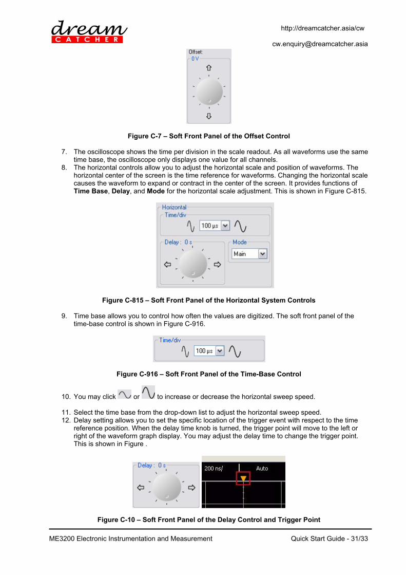
Figure C-7 – Soft Front Panel of the Offset Control
7. The oscilloscope shows the time per division in the scale readout. As all waveforms use the same time base, the oscilloscope only displays one value for all channels.
8. The horizontal controls allow you to adjust the horizontal scale and position of waveforms. The horizontal center of the screen is the time reference for waveforms. Changing the horizontal scale causes the waveform to expand or contract in the center of the screen. It provides functions of Time Base, Delay, and Mode for the horizontal scale adjustment. This is shown in Figure C-815.
Figure C-815 – Soft Front Panel of the Horizontal System Controls
9. Time base allows you to control how often the values are digitized. The soft front panel of the time-base control is shown in Figure C-916.
Figure C-916 – Soft Front Panel of the Time-Base Control
10. You may click or to increase or decrease the horizontal sweep speed.
11. Select the time base from the drop-down list to adjust the horizontal sweep speed. 12. Delay setting allows you to set the specific location of the trigger event with respect to the time
reference position. When the delay time knob is turned, the trigger point will move to the left or right of the waveform graph display. You may adjust the delay time to change the trigger point. This is shown in Figure .
Figure C-10 – Soft Front Panel of the Delay Control and Trigger Point

http://dreamcatcher.asia/cw [email protected]
ME3200 Electronic Instrumentation and Measurement
Quick Start Guide - 32/33
13. You may click or to increase or decrease the delay time. 14. The oscilloscope offers three types of horizontal mode functions, which are Main Mode, Roll
Mode, and XY Mode. You may select the horizontal mode by clicking the drop-down list under Mode.
Measurement and Cursor Controls
1. The Measurements & Cursors button is located on the toolbar of the soft front panel.
2. Click to activate the automated measurement and cursor system. This will display the window as shown below:
Figure C-11 – Soft Front Panel of the Measurement and Cursor Controls
3. The oscilloscope provides three types of settings for marker property, which are Auto, Manual,
and Off. 4. Auto marker automatically places the cursors on the graph based on the selected
measurements. 5. Manual marker allows the cursors to be placed manually on the graph for customized
measurements. This will enable the Cursors panel. 6. Off will disable the graph markers from the graph display. 7. If the Manual marker is selected, the Cursors control will be enabled. This is shown in Figure .
http://dreamcatcher.asia/cw [email protected]
ME3200 Electronic Instrumentation and Measurement
Quick Start Guide - 33/33
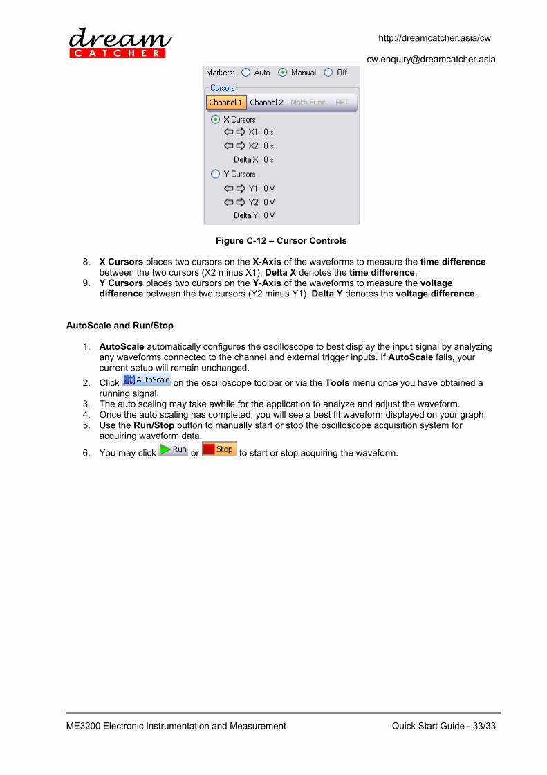
Figure C-12 – Cursor Controls
8. X Cursors places two cursors on the X-Axis of the waveforms to measure the time difference between the two cursors (X2 minus X1). Delta X denotes the time difference.
9. Y Cursors places two cursors on the Y-Axis of the waveforms to measure the voltage difference between the two cursors (Y2 minus Y1). Delta Y denotes the voltage difference.
AutoScale and Run/Stop
1. AutoScale automatically configures the oscilloscope to best display the input signal by analyzing any waveforms connected to the channel and external trigger inputs. If AutoScale fails, your current setup will remain unchanged.
2. Click on the oscilloscope toolbar or via the Tools menu once you have obtained a running signal.
3. The auto scaling may take awhile for the application to analyze and adjust the waveform. 4. Once the auto scaling has completed, you will see a best fit waveform displayed on your graph. 5. Use the Run/Stop button to manually start or stop the oscilloscope acquisition system for
acquiring waveform data.
6. You may click or to start or stop acquiring the waveform.

http://dreamcatcher.asia/cw [email protected]
ME3200 Electronic Instrumentation and Measurement
Quick Start Guide - 34/34
Contact Us Acehub Vista Sdn Bhd (785702-P) A member of the DreamCatcher group 10, Persiaran Mahsuri 1/2, Sunway Tunas, Bayan Lepas, 11900 Penang, Malaysia. All rights reserved. No part of this document may be reproduced or transmitted in any form or by any means, electronic, mechanical, photocopying, recording, or otherwise, without prior written permission of Acehub Vista Sdn. Bhd. Every effort has been made to ensure that the information in this manual is accurate. Acehub Vista Sdn. Bhd. is not responsible for printing or clerical errors. Trademark Acknowledgements DreamCatcherTM is the trademark of Dream Catcher Consulting Sdn. Bhd. Microsoft and Windows are trademarks of Microsoft Corporation in the United States and/or other countries. All other copyrights and trademarks belong to their respective owners.
© 2010 Acehub Vista Sdn. Bhd.