md-200 & 250 - amazon web services€¦ · baffle for manitowoc cubers .....13 baffle for...
TRANSCRIPT
Manitowoc Beverage Equipment2100 Future Drive Sellersburg, IN 47172-1868Tel: 812.246.7000, 800.367.4233 Fax: 812.246.9922www.manitowocbeverage.com
In accordance with our policy of continuous product development andimprovement, this information is subject to change at any time without notice.
October 19, 2006 REV6
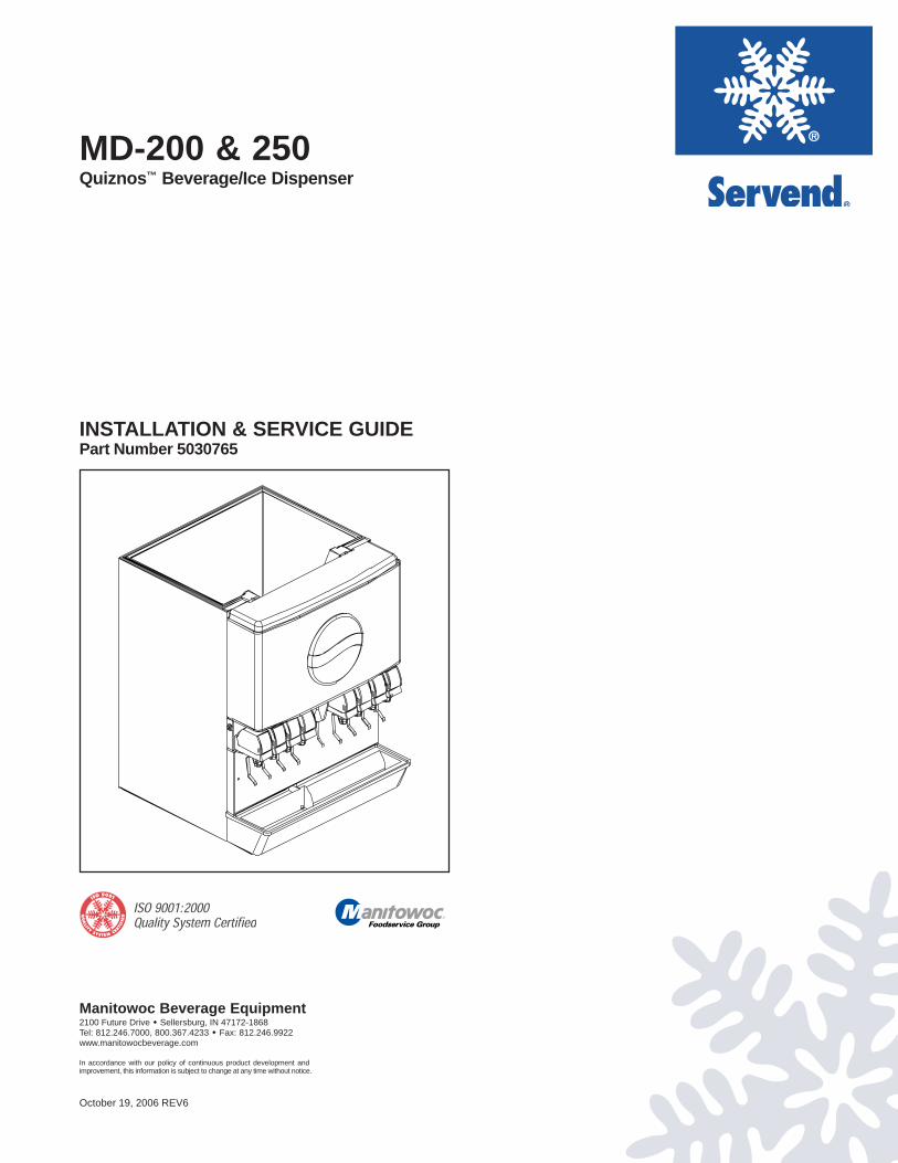
MD-200 & 250Quiznos™ Beverage/Ice Dispenser
INSTALLATION & SERVICE GUIDEPart Number 5030765

FOREWORDManitowoc Beverage Equipment (MBE) developed this manual as a reference guide for the owner/operator, service agent, and installer of this equipment. Please read this manual before installationor operation of the machine. A qualified service technician should perform installation and start-up of this equipment, consult the Troubleshooting Guide within this manual for service assistance.
If you cannot correct the service problem, call your MBE Service Agent or Distributor. Always have your model andserial number available when you call.
Your Service Agent___________________________________________________________________
Service Agent Telephone Number ______________________________________________________
Your Local MBE Distributor ___________________________________________________________
Distributor Telephone Number _________________________________________________________
Model Number ______________________________________________________________________
Serial Number _______________________________________________________________________
Installation Date _____________________________________________________________________
UNPACKING AND INSPECTIONNote: The unit was thoroughly inspected before leaving the factory. Any damage or irregularities shouldbe noted at the time of delivery.
WARRANTY INFORMATIONConsult your local MBE Distributor for terms and conditions of your warranty. Your warranty specificallyexcludes all beverage valve brixing, general adjustments, cleaning, accessories and related servicing.
Your warranty card must be returned to Manitowoc Beverage Equipment to activate the warranty on thisequipment. If a warranty card is not returned, the warranty period can begin when the equipment leavesthe MBE factory.
No equipment may be returned to Manitowoc Beverage Equipment without a written Return GoodsAuthorization (RGA). Equipment returned without an RGA will be refused by MBE’s Receiving Departmentand returned to the sender at the sender’s expense.
Please contact your local MBE distributor for return procedures.
TABLE OF CONTENTSFOREWORD ........................................................................................................ 3UNPACKING AND INSPECTION ........................................................................ 3WARRANTY INFORMATION ............................................................................... 3SAFETY ............................................................................................................... 6
IMPORTANT SAFETY INSTRUCTIONS ............................................................................. 6
CARBON DIOXIDE WARNING........................................................................................... 6
QUALIFIED SERVICE PERSONNEL .................................................................................. 6
SHIPPING, STORAGE, AND RELOCATION ....................................................................... 6
ADDITIONAL WARNINGS ................................................................................................. 6
GROUNDING IN STRUCTIONS ......................................................................................... 7
INSTALLATION .................................................................................................... 8PRE-INSTALLATION CHECK LIST .................................................................................... 8
LEGS ................................................................................................................................ 8
INTERNAL CARBONATION ............................................................................................... 8
COLD CARB BAG-IN-BOX (B-I-B) SYSTEM ....................................................................... 9
COLD CARB SYSTEM PRESSURES ................................................................................. 9
UNIT INSTALLATION .......................................................................................................10
DRAINAGE OPTIONS ......................................................................................................10
CARB TANK PURGE TUBE ROUTING ............................................................................. 11
TOP MOUNTED ICEMAKER REQUIREMENTS .................................................................12
BAFFLE FOR MANITOWOC™ CUBERS ..........................................................................13
BAFFLE FOR "Q" SERIES ICE MACHINES ......................................................................13
MANUAL FILL LID FOR DISPENSERS MOUNTED WITH A CUBER .................................13
PLUMBING DIAGRAM LOCATION & FLEX MANIFOLD ...................................................14
DIAGRAM ........................................................................................................................14
OPERATION ...................................................................................................... 15UNIT INSPECTION ...........................................................................................................15
ICE STORAGE AND DISPENSING ...................................................................................15
COLD PLATE BEVERAGE COOLING ...............................................................................15
ROCKING CHUTE ICE DISPENSING ................................................................................15
BEVERAGE VALVES ........................................................................................................16
POST-MIX BEVERAGE DISPENSERS .............................................................................16
BACK ROOM PACKAGE ..................................................................................................17
BAG-IN-BOX SYSTEM .....................................................................................................17
COUNTERTOP MEASUREMENTS ....................................................................................18
SPECIFICATIONS ............................................................................................................19
115V/220V NON ADJUSTABLE AGITATION TIMER ..........................................................20
ICE CHUTE SEQUENCE OF OPERATION .........................................................................20
5
Installation and Service Manual
USER MAINTENANCE...................................................................................... 21HOW TO DISASSEMBLE FOR CLEANING OR MAINTENANCE .......................................21
DAILY CLEANING.............................................................................................................24
MONTHLY CLEANING ......................................................................................................25
BEVERAGE SYSTEM CLEANING .....................................................................................26
BAG-IN-BOX SYSTEM .....................................................................................................26
PREVENTATIVE MAINTENANCE ......................................................................................27
EXPLODED VIEWS, PARTS & DIAGRAMS ..................................................... 28MD-200 & 250 QUIZNOS™ UNIT EXPLODED VIEW .........................................................28
MD-200 & 250 QUIZNOS™ UNIT PARTS LIST .................................................................29
MD-200 QUIZNOS™ MERCHANDISER .............................................................................30
MD-250 QUIZNOS™ MERCHANDISER .............................................................................31
WIRING MD-200 & 250 QUIZNOS™ UNIT 115V ...............................................................32
TROUBLESHOOTING ....................................................................................... 33PUMP...............................................................................................................................33
DRINKS............................................................................................................................34
DRINKS............................................................................................................................35
LIQUID LEVEL CONTROL ................................................................................................36
INDEX ................................................................................................................ 39
TABLE OF CONTENTS
SAFETYIMPORTANT SAFETY INSTRUCTIONS
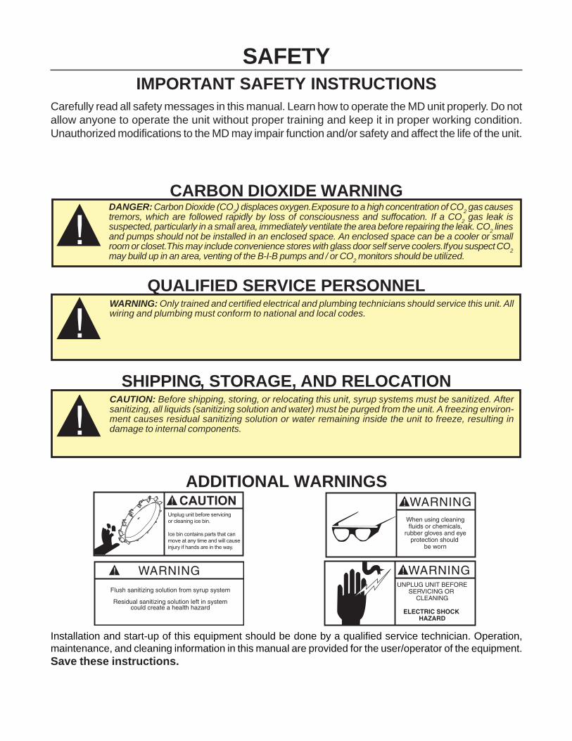
Carefully read all safety messages in this manual. Learn how to operate the MD unit properly. Do notallow anyone to operate the unit without proper training and keep it in proper working condition.Unauthorized modifications to the MD may impair function and/or safety and affect the life of the unit.
CARBON DIOXIDE WARNING
QUALIFIED SERVICE PERSONNEL
SHIPPING, STORAGE, AND RELOCATION
ADDITIONAL WARNINGS
Installation and start-up of this equipment should be done by a qualified service technician. Operation,maintenance, and cleaning information in this manual are provided for the user/operator of the equipment.Save these instructions.
DANGER: Carbon Dioxide (CO2) displaces oxygen. Exposure to a high concentration of CO
2 gas causes
tremors, which are followed rapidly by loss of consciousness and suffocation. If a CO2 gas leak is
suspected, particularly in a small area, immediately ventilate the area before repairing the leak. CO2 lines
and pumps should not be installed in an enclosed space. An enclosed space can be a cooler or smallroom or closet. This may include convenience stores with glass door self serve coolers. If you suspect CO
2may build up in an area, venting of the B-I-B pumps and / or CO
2 monitors should be utilized.
WARNING: Only trained and certified electrical and plumbing technicians should service this unit. Allwiring and plumbing must conform to national and local codes.
CAUTION: Before shipping, storing, or relocating this unit, syrup systems must be sanitized. Aftersanitizing, all liquids (sanitizing solution and water) must be purged from the unit. A freezing environ-ment causes residual sanitizing solution or water remaining inside the unit to freeze, resulting indamage to internal components.
7
Installation and Service Manual
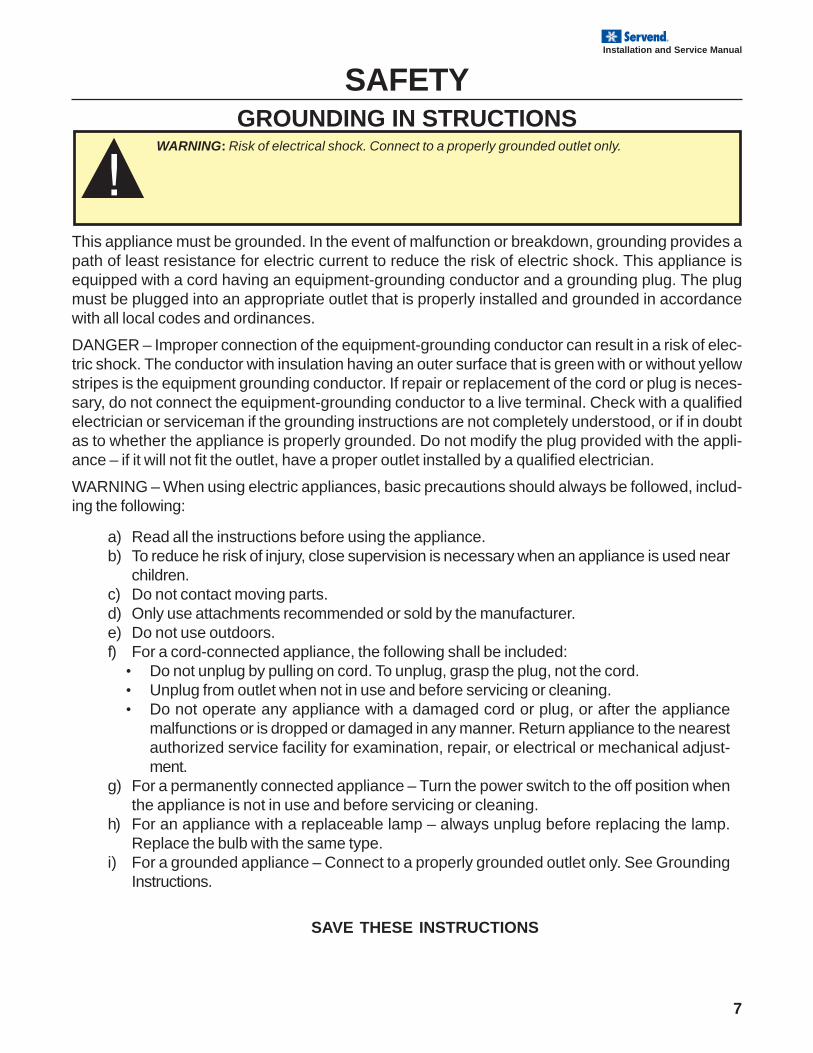
GROUNDING IN STRUCTIONS
SAFETY
This appliance must be grounded. In the event of malfunction or breakdown, grounding provides apath of least resistance for electric current to reduce the risk of electric shock. This appliance isequipped with a cord having an equipment-grounding conductor and a grounding plug. The plugmust be plugged into an appropriate outlet that is properly installed and grounded in accordancewith all local codes and ordinances.
DANGER – Improper connection of the equipment-grounding conductor can result in a risk of elec-tric shock. The conductor with insulation having an outer surface that is green with or without yellowstripes is the equipment grounding conductor. If repair or replacement of the cord or plug is neces-sary, do not connect the equipment-grounding conductor to a live terminal. Check with a qualifiedelectrician or serviceman if the grounding instructions are not completely understood, or if in doubtas to whether the appliance is properly grounded. Do not modify the plug provided with the appli-ance – if it will not fit the outlet, have a proper outlet installed by a qualified electrician.
WARNING – When using electric appliances, basic precautions should always be followed, includ-ing the following:
a) Read all the instructions before using the appliance.b) To reduce he risk of injury, close supervision is necessary when an appliance is used near
children.c) Do not contact moving parts.d) Only use attachments recommended or sold by the manufacturer.e) Do not use outdoors.f) For a cord-connected appliance, the following shall be included:
• Do not unplug by pulling on cord. To unplug, grasp the plug, not the cord.• Unplug from outlet when not in use and before servicing or cleaning.• Do not operate any appliance with a damaged cord or plug, or after the appliance
malfunctions or is dropped or damaged in any manner. Return appliance to the nearestauthorized service facility for examination, repair, or electrical or mechanical adjust-ment.
g) For a permanently connected appliance – Turn the power switch to the off position whenthe appliance is not in use and before servicing or cleaning.
h) For an appliance with a replaceable lamp – always unplug before replacing the lamp.Replace the bulb with the same type.
i) For a grounded appliance – Connect to a properly grounded outlet only. See GroundingInstructions.
SAVE THESE INSTRUCTIONS
WARNING: Risk of electrical shock. Connect to a properly grounded outlet only.
8
Installation and Service Manual
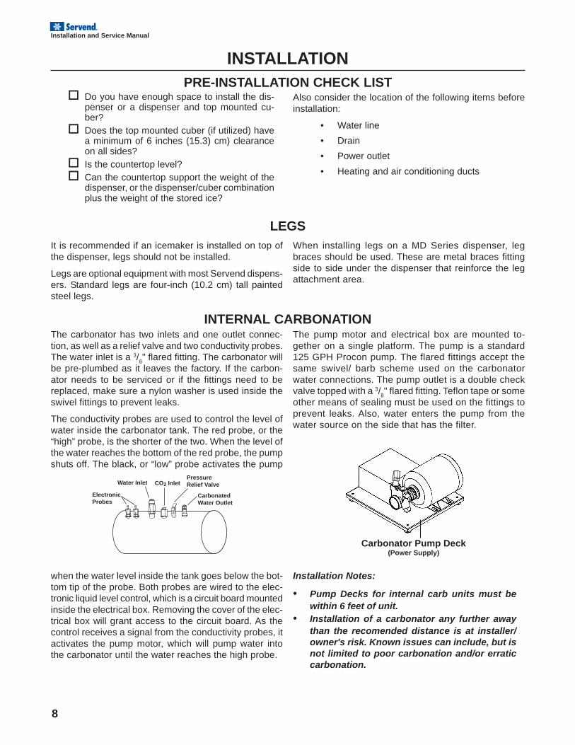
Electronic Probes
Water Inlet
Carbonated Water Outlet
Pressure Relief ValveCO2 Inlet
Carbonator Pump Deck(Power Supply)
INSTALLATIONPRE-INSTALLATION CHECK LIST
Do you have enough space to install the dis-penser or a dispenser and top mounted cu-ber?Does the top mounted cuber (if utilized) havea minimum of 6 inches (15.3) cm) clearanceon all sides?Is the countertop level?Can the countertop support the weight of thedispenser, or the dispenser/cuber combinationplus the weight of the stored ice?
Also consider the location of the following items beforeinstallation:
• Water line
• Drain
• Power outlet
• Heating and air conditioning ducts
LEGSIt is recommended if an icemaker is installed on top ofthe dispenser, legs should not be installed.
Legs are optional equipment with most Servend dispens-ers. Standard legs are four-inch (10.2 cm) tall paintedsteel legs.
When installing legs on a MD Series dispenser, legbraces should be used. These are metal braces fittingside to side under the dispenser that reinforce the legattachment area.
INTERNAL CARBONATIONThe carbonator has two inlets and one outlet connec-tion, as well as a relief valve and two conductivity probes.The water inlet is a 3/
8" flared fitting. The carbonator will
be pre-plumbed as it leaves the factory. If the carbon-ator needs to be serviced or if the fittings need to bereplaced, make sure a nylon washer is used inside theswivel fittings to prevent leaks.
The conductivity probes are used to control the level ofwater inside the carbonator tank. The red probe, or the“high” probe, is the shorter of the two. When the level ofthe water reaches the bottom of the red probe, the pumpshuts off. The black, or “low” probe activates the pump
when the water level inside the tank goes below the bot-tom tip of the probe. Both probes are wired to the elec-tronic liquid level control, which is a circuit board mountedinside the electrical box. Removing the cover of the elec-trical box will grant access to the circuit board. As thecontrol receives a signal from the conductivity probes, itactivates the pump motor, which will pump water intothe carbonator until the water reaches the high probe.
The pump motor and electrical box are mounted to-gether on a single platform. The pump is a standard125 GPH Procon pump. The flared fittings accept thesame swivel/ barb scheme used on the carbonatorwater connections. The pump outlet is a double checkvalve topped with a 3/
8" flared fitting. Teflon tape or some
other means of sealing must be used on the fittings toprevent leaks. Also, water enters the pump from thewater source on the side that has the filter.
Installation Notes:
• Pump Decks for internal carb units must bewithin 6 feet of unit.
• Installation of a carbonator any further awaythan the recomended distance is at installer/owner's risk. Known issues can include, but isnot limited to poor carbonation and/or erraticcarbonation.
9
Installation and Service Manual
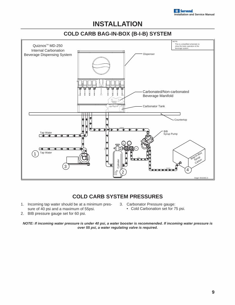
INSTALLATIONCOLD CARB BAG-IN-BOX (B-I-B) SYSTEM
COLD CARB SYSTEM PRESSURES1. Incoming tap water should be at a minimum pres-
sure of 40 psi and a maximum of 55psi.2. BIB pressure gauge set for 60 psi.
3. Carbonator Pressure gauge:• Cold Carbonation set for 75 psi.
NOTE: If incoming water pressure is under 40 psi, a water booster is recommended. If incoming water pressure isover 55 psi, a water regulating valve is required.
CO
2
1800 75
SYRUP
2CO
SYRUP
60
Dispenser
Tap Water1
Tap Water
3 Cyl
inde
r2
CO 2
Internal CarbonationQuiznosTM MD-250
Beverage Dispensing System
Bag-In-Box
4
CartonSyrup
Syrup PumpBIB
Countertop
show the basic operation of theThis is a simplified schematic to
beverage system.
NOTE:
Dwg#: 5010301-0
Carbonator Tank
Carbonated/Non-carbonatedBeverage Manifold
10
Installation and Service Manual
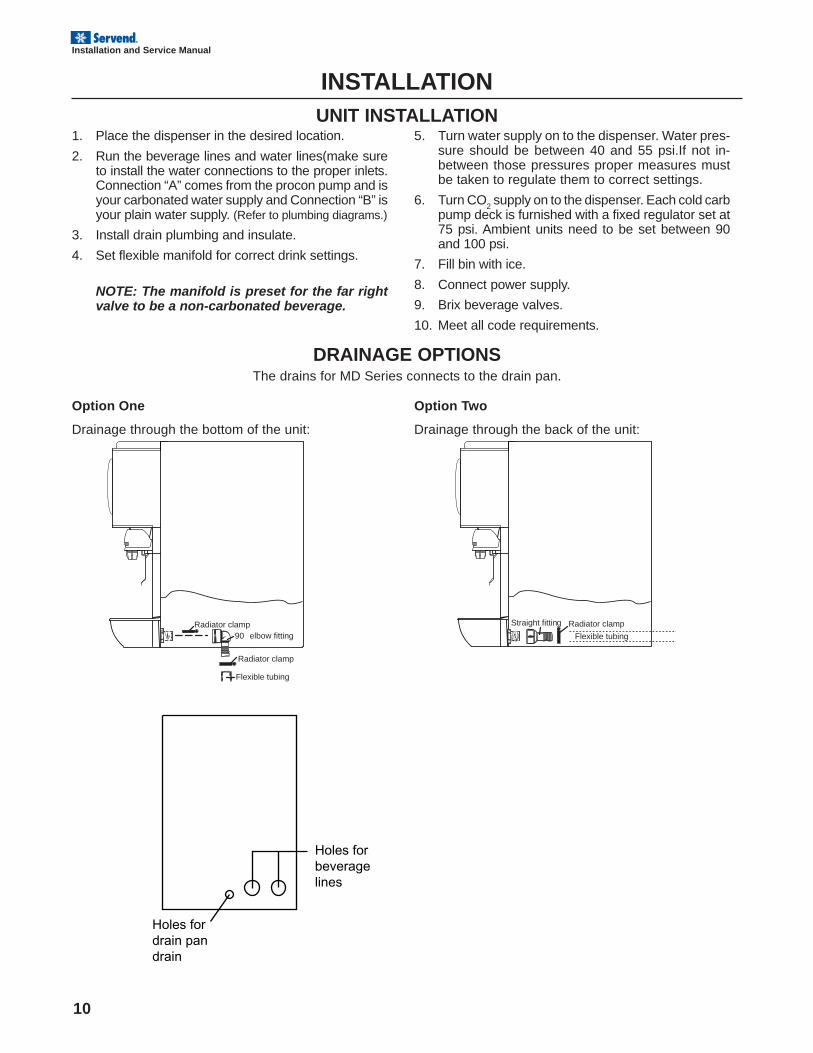
DRAINAGE OPTIONS
INSTALLATIONUNIT INSTALLATION
The drains for MD Series connects to the drain pan.
1. Place the dispenser in the desired location.
2. Run the beverage lines and water lines(make sureto install the water connections to the proper inlets.Connection “A” comes from the procon pump and isyour carbonated water supply and Connection “B” isyour plain water supply. (Refer to plumbing diagrams.)
3. Install drain plumbing and insulate.
4. Set flexible manifold for correct drink settings.
5. Turn water supply on to the dispenser. Water pres-sure should be between 40 and 55 psi.If not in-between those pressures proper measures mustbe taken to regulate them to correct settings.
6. Turn CO2 supply on to the dispenser. Each cold carb
pump deck is furnished with a fixed regulator set at75 psi. Ambient units need to be set between 90and 100 psi.
7. Fill bin with ice.
8. Connect power supply.
9. Brix beverage valves.
10. Meet all code requirements.
Option One
Drainage through the bottom of the unit:
Option Two
Drainage through the back of the unit:
NOTE: The manifold is preset for the far rightvalve to be a non-carbonated beverage.
90� elbow fittingRadiator clamp
Radiator clamp
Flexible tubing
Straight fitting Radiator clampFlexible tubing
Holes for beverage lines
Holes for drain pan drain
11
Installation and Service Manual
ATo Drain
A
B
A
C
Drain PanPressure Relif Valve
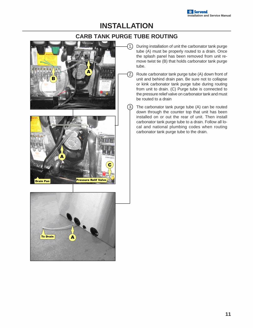
INSTALLATIONCARB TANK PURGE TUBE ROUTING
1. During installation of unit the carbonator tank purgetube (A) must be properly routed to a drain. Oncethe splash panel has been removed from unit re-move twist tie (B) that holds carbonator tank purgetube.
2. Route carbonator tank purge tube (A) down front ofunit and behind drain pan. Be sure not to collapseor kink carbonator tank purge tube during routingfrom unit to drain. (C) Purge tube is connected tothe pressure relief valve on carbonator tank and mustbe routed to a drain
3. The carbonator tank purge tube (A) can be routeddown through the counter top that unit has beeninstalled on or out the rear of unit. Then installcarbonator tank purge tube to a drain. Follow all lo-cal and national plumbing codes when routingcarbonator tank purge tube to the drain.
12
Installation and Service Manual
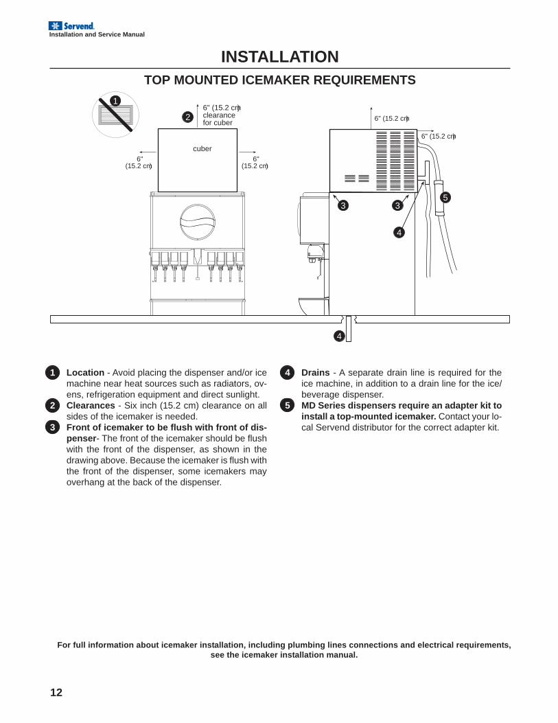
INSTALLATIONTOP MOUNTED ICEMAKER REQUIREMENTS
1 Location - Avoid placing the dispenser and/or icemachine near heat sources such as radiators, ov-ens, refrigeration equipment and direct sunlight.
2 Clearances - Six inch (15.2 cm) clearance on allsides of the icemaker is needed.
3 Front of icemaker to be flush with front of dis-penser- The front of the icemaker should be flushwith the front of the dispenser, as shown in thedrawing above. Because the icemaker is flush withthe front of the dispenser, some icemakers mayoverhang at the back of the dispenser.
4 Drains - A separate drain line is required for theice machine, in addition to a drain line for the ice/beverage dispenser.
5 MD Series dispensers require an adapter kit toinstall a top-mounted icemaker. Contact your lo-cal Servend distributor for the correct adapter kit.
For full information about icemaker installation, including plumbing lines connections and electrical requirements,see the icemaker installation manual.
6" (15.2 cm)clearancefor cuber
cuber
53
4
3
2
4
6"(15.2 cm)
6"(15.2 cm)
6" (15.2 cm)
6" (15.2 cm)
1
13
Installation and Service Manual
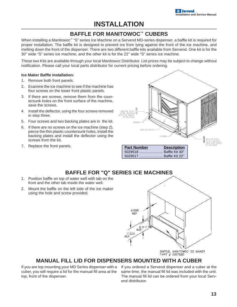
Part Number Description5029518 ........................ Baffle Kit 30”5029517 ........................ Baffle Kit 22”
When installing a Manitowoc™ “S” series Ice Machine on a Servend MD-series dispenser, a baffle kit is required forproper installation. The baffle kit is designed to prevent ice from lying against the front of the ice machine, andmelting down the front of the dispenser. There are two different baffle kits available from Servend. One kit is for the30" wide “S” series ice machine, and the other kit is for the 22" wide “S” series ice machine.
These two Kits are available through your local Manitowoc Distributor. List prices may be subject to change withoutnotification. Please call your local parts distributor for current pricing before ordering.
Ice Maker Baffle Installation:1. Remove both front panels.
2. Examine the ice machine to see if the machine hasfour screws on the lower front plastic panels.
3. If there are screws, remove them from the coun-tersunk holes on the front surface of the machine,save the screws.
4. Install the deflector, using the four screws removedin step three.
5. Four screws and two backing plates are in the kit.
6. If there are no screws on the ice machine (step 2),pierce the thin plastic countersunk holes, install thebacking plates and install the deflector using thescrews from the kit.
7. Replace the front panels.
INSTALLATIONBAFFLE FOR MANITOWOC™ CUBERS
BAFFLE FOR "Q" SERIES ICE MACHINES
MANUAL FILL LID FOR DISPENSERS MOUNTED WITH A CUBERIf you are top mounting your MD Series dispenser with acuber, you will require a lid for the manual fill area at thetop, front of the dispenser.
If you ordered a Servend dispenser and a cuber at thesame time, the manual fill lid was included with the unit.The manual fill lid can be ordered from your local Serv-end distributor.
1. Position baffle on top of water well with tab on thefront and the other tab inside the water well.
2. Mount the baffle on the left side of the ice makerusing the hole and screw provided.
14
Installation and Service Manual
INSTALLATIONPLUMBING DIAGRAM LOCATION & FLEX MANIFOLD
DIAGRAM
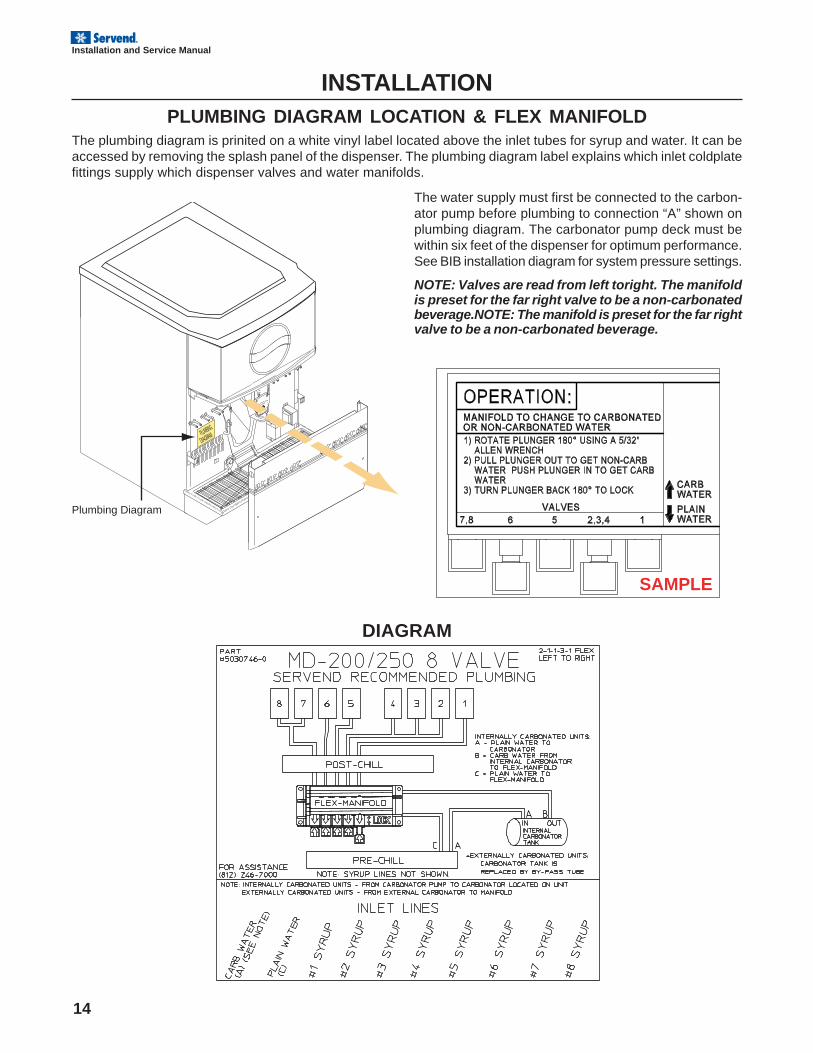
The plumbing diagram is prinited on a white vinyl label located above the inlet tubes for syrup and water. It can beaccessed by removing the splash panel of the dispenser. The plumbing diagram label explains which inlet coldplatefittings supply which dispenser valves and water manifolds.
The water supply must first be connected to the carbon-ator pump before plumbing to connection “A” shown onplumbing diagram. The carbonator pump deck must bewithin six feet of the dispenser for optimum performance.See BIB installation diagram for system pressure settings.
NOTE: Valves are read from left toright. The manifoldis preset for the far right valve to be a non-carbonatedbeverage.NOTE: The manifold is preset for the far rightvalve to be a non-carbonated beverage.
PLUMBING
DIAGRAM
PUSH FOR ICE
PUSH FOR ICE
4
Plumbing Diagram
SAMPLE
15
Installation and Service Manual
OPERATIONUNIT INSPECTION
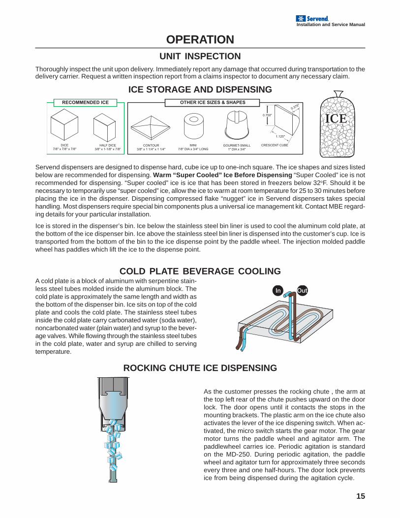
Thoroughly inspect the unit upon delivery. Immediately report any damage that occurred during transportation to thedelivery carrier. Request a written inspection report from a claims inspector to document any necessary claim.
ICE STORAGE AND DISPENSING
Servend dispensers are designed to dispense hard, cube ice up to one-inch square. The ice shapes and sizes listedbelow are recommended for dispensing. Warm “Super Cooled” Ice Before Dispensing “Super Cooled” ice is notrecommended for dispensing. “Super cooled” ice is ice that has been stored in freezers below 32oF. Should it benecessary to temporarily use “super cooled” ice, allow the ice to warm at room temperature for 25 to 30 minutes beforeplacing the ice in the dispenser. Dispensing compressed flake “nugget” ice in Servend dispensers takes specialhandling. Most dispensers require special bin components plus a universal ice management kit. Contact MBE regard-ing details for your particular installation.
Ice is stored in the dispenser’s bin. Ice below the stainless steel bin liner is used to cool the aluminum cold plate, atthe bottom of the ice dispenser bin. Ice above the stainless steel bin liner is dispensed into the customer’s cup. Ice istransported from the bottom of the bin to the ice dispense point by the paddle wheel. The injection molded paddlewheel has paddles which lift the ice to the dispense point.
COLD PLATE BEVERAGE COOLINGA cold plate is a block of aluminum with serpentine stain-less steel tubes molded inside the aluminum block. Thecold plate is approximately the same length and width asthe bottom of the dispenser bin. Ice sits on top of the coldplate and cools the cold plate. The stainless steel tubesinside the cold plate carry carbonated water (soda water),noncarbonated water (plain water) and syrup to the bever-age valves. While flowing through the stainless steel tubesin the cold plate, water and syrup are chilled to servingtemperature.
ROCKING CHUTE ICE DISPENSING
As the customer presses the rocking chute , the arm atthe top left rear of the chute pushes upward on the doorlock. The door opens until it contacts the stops in themounting brackets. The plastic arm on the ice chute alsoactivates the lever of the ice dispening switch. When ac-tivated, the micro switch starts the gear motor. The gearmotor turns the paddle wheel and agitator arm. Thepaddlewheel carries ice. Periodic agitation is standardon the MD-250. During periodic agitation, the paddlewheel and agitator turn for approximately three secondsevery three and one half-hours. The door lock preventsice from being dispensed during the agitation cycle.

16
Installation and Service Manual
1 2 3 4 5 6 7 8
MANIFOLD MANIFOLD
COLD PLATE
Servend Recommended Plumbing 3-1-1-3 FLEX6005433RI
NOTE: SYRUP LINES NOT SHOWN
#1 S
YR
UP
#2 S
YR
UP
#3 S
YR
UP
#4 S
YR
UP
#4 W
ATE
R/S
OD
A#1
, #2,
#3
WAT
ER/S
OD
A#6
, #7,
#8
WAT
ER/S
OD
A#5
WAT
ER
/SO
DA
#8 S
YR
UP
#7 S
YR
UP
#6 S
YR
UP
#5 S
YR
UP
PLUMBING DIAGRAM EXAMPLEPLUMBING DIAGRAM EXAMPLE
EXAMPLE:Water / soda manifold is supplied with water by the inlet labeled ‘#1, #2, #3, WATER / SODA’
EXAMPLE:Valve 8 is supplied with syrup by the inlet labled '#8 SYRUP'
OPERATIONBEVERAGE VALVES
Post-mix beverage valves are designed to precisely meter the flow of both water and syrup to obtain the proper mixingratio. The syrup and soda water components of the post-mix beverage are mixed as they leave the beverage valve.
POST-MIX BEVERAGE DISPENSERS
Post-Mix
Most beverage systems are Post-Mix. Permanent dis-pensing locations with a mid to high volume dispensinghave Post-Mix systems, such as self-service dispens-ers in Convenience Stores, Restaurants and Cafete-rias.
Post-Mix means that syrup and carbonated water (orplain tap water for non-carbonated drinks) are mixed to-gether in the valve nozzle of the dispenser, just beforethe finished beverage flows into the customer’s cup.
A memory peg for the meaning of Post-Mix is that the syrupand water are mixed after leaving the beverage valve.
Post-Mix System
The most common Post-Mix System is the Bag-in-Box(BIB) - Most often, five gallons of syrup is stored in aplastic bag inside a carton.
Plumbing Diagram Label
The plumbing diagram lebel explains which inlet coldplate fittings supply which dispenser valves.
17
Installation and Service Manual
OPERATIONBACK ROOM PACKAGE
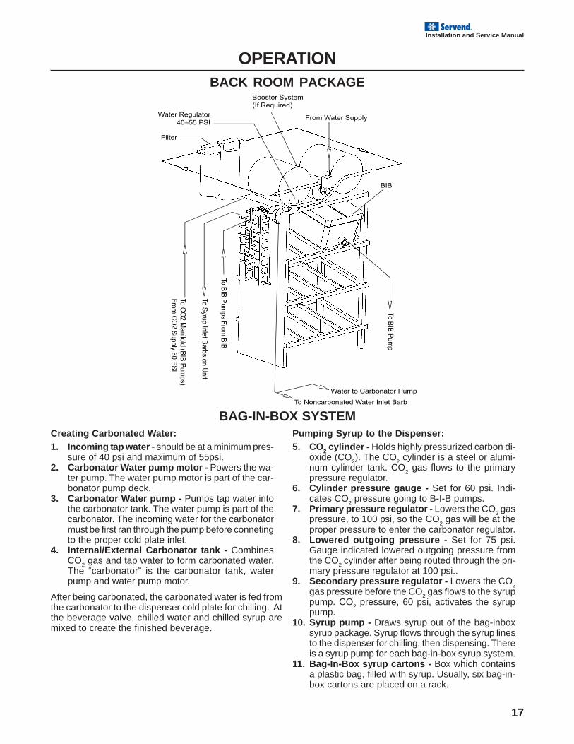
BAG-IN-BOX SYSTEMCreating Carbonated Water:1. Incoming tap water - should be at a minimum pres-
sure of 40 psi and maximum of 55psi.2. Carbonator Water pump motor - Powers the wa-
ter pump. The water pump motor is part of the car-bonator pump deck.
3. Carbonator Water pump - Pumps tap water intothe carbonator tank. The water pump is part of thecarbonator. The incoming water for the carbonatormust be first ran through the pump before connetingto the proper cold plate inlet.
4. Internal/External Carbonator tank - CombinesCO
2 gas and tap water to form carbonated water.
The “carbonator” is the carbonator tank, waterpump and water pump motor.
After being carbonated, the carbonated water is fed fromthe carbonator to the dispenser cold plate for chilling. Atthe beverage valve, chilled water and chilled syrup aremixed to create the finished beverage.
Pumping Syrup to the Dispenser:5. CO2 cylinder - Holds highly pressurized carbon di-
oxide (CO2). The CO
2 cylinder is a steel or alumi-
num cylinder tank. CO2 gas flows to the primary
pressure regulator.6. Cylinder pressure gauge - Set for 60 psi. Indi-
cates CO2 pressure going to B-I-B pumps.
7. Primary pressure regulator - Lowers the CO2 gas
pressure, to 100 psi, so the CO2 gas will be at the
proper pressure to enter the carbonator regulator.8. Lowered outgoing pressure - Set for 75 psi.
Gauge indicated lowered outgoing pressure fromthe CO
2 cylinder after being routed through the pri-
mary pressure regulator at 100 psi..9. Secondary pressure regulator - Lowers the CO
2gas pressure before the CO
2 gas flows to the syrup
pump. CO2 pressure, 60 psi, activates the syrup
pump.10. Syrup pump - Draws syrup out of the bag-inbox
syrup package. Syrup flows through the syrup linesto the dispenser for chilling, then dispensing. Thereis a syrup pump for each bag-in-box syrup system.
11. Bag-In-Box syrup cartons - Box which containsa plastic bag, filled with syrup. Usually, six bag-in-box cartons are placed on a rack.
18
Installation and Service Manual
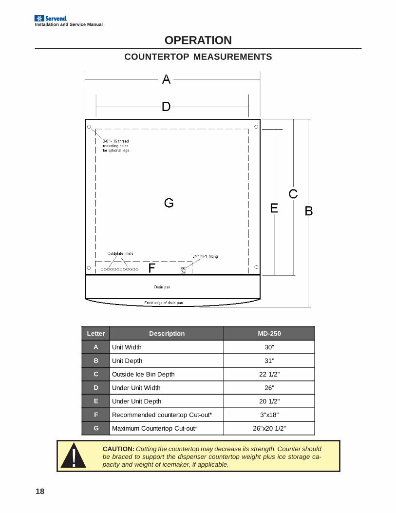
Letter Description MD-250
A Unit Width 30”
B Unit Depth 31"
C Outside Ice Bin Depth 22 1/2"
D Under Unit Width 26"
E Under Unit Depth 20 1/2"
F Recommended countertop Cut-out* 3"x18"
G Maximum Countertop Cut-out* 26"x20 1/2"
OPERATIONCOUNTERTOP MEASUREMENTS
CAUTION: Cutting the countertop may decrease its strength. Counter shouldbe braced to support the dispenser countertop weight plus ice storage ca-pacity and weight of icemaker, if applicable.
19
Installation and Service Manual
OPERATIONSPECIFICATIONS
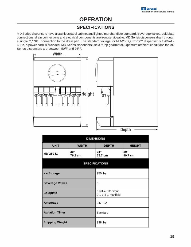
MD Series dispensers have a stainless steel cabinet and lighted merchandiser standard. Beverage valves, coldplateconnections, drain connections and electrical components are front serviceable. MD Series dispensers drain througha single 3/
4" NPT connection to the drain pan. The standard voltage for MD-250 Quiznos™ dispenser is 120VAC-
60Hz, a power cord is provided. MD Series dispensers use a 1/7 hp gearmotor. Optimum ambient conditions for MD
Series dispensers are between 500F and 950F.
DIMENSIONS
UNIT WIDTH DEPTH HEIGHT
MD-250-IC30"76.2 cm
31"78.7 cm
39"99.7 cm
SPECIFICATIONS
Ice Storage 250 lbs
Beverage Valves 8
Coldplate 8 valve: 12 circuit2-1-1-3-1 manifold
Amperage 2.5 FLA
Agitation Timer Standard
Shipping Weight 338 lbs
20
Installation and Service Manual
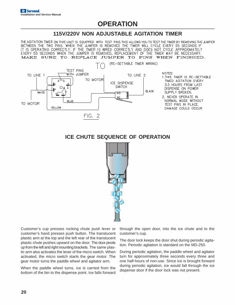
OPERATION115V/220V NON ADJUSTABLE AGITATION TIMER
Customer’s cup presses rocking chute push lever orcustomer’s hand presses push button. The translucentplastic arm at the top and the left rear of the translucentplastic chute pushes upward on the door. The door pivotsup from the left and right mounting brackets. The same plas-tic arm also activates the lever of the micro switch. Whenactivated, the micro switch starts the gear motor. Thegear motor turns the paddle wheel and agitator arm.
When the paddle wheel turns, ice is carried from thebottom of the bin to the dispense point. Ice falls forward
ICE CHUTE SEQUENCE OF OPERATION
through the open door, into the ice chute and to thecustomer’s cup.
The door lock keeps the door shut during periodic agita-tion. Periodic agitation is standard on the MD-250.
During periodic agitation, the paddle wheel and agitatorturn for approximately three seconds every three andone half-hours of non-use. Since ice is brought forwardduring periodic agitation, ice would fall through the icedispense door if the door lock was not present.
21
Installation and Service Manual
USER MAINTENANCEHOW TO DISASSEMBLE FOR CLEANING OR MAINTENANCE
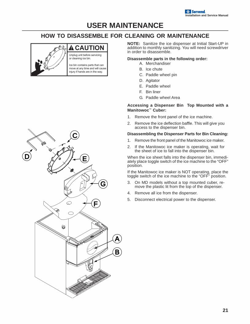
NOTE: Sanitize the ice dispenser at Initial Start-UP inaddition to monthly sanitizing. You will need screwdriverin order to disassemble.
Disassemble parts in the following order:A. MerchandiserB. Ice chuteC. Paddle wheel pinD. AgitatorE. Paddle wheelF. Bin linerG. Paddle wheel Area
Accessing a Dispenser Bin Top Mounted with aManitowoc™ Cuber:
1. Remove the front panel of the ice machine.
2. Remove the ice deflection baffle. This will give youaccess to the dispenser bin.
Disassembling the Dispenser Parts for Bin Cleaning:
1. Remove the front panel of the Manitowoc ice maker.
2. If the Manitowoc ice maker is operating, wait forthe sheet of ice to fall into the dispenser bin.
When the ice sheet falls into the dispenser bin, immedi-ately place toggle switch of the ice machine to the “OFF”position.
If the Manitowoc ice maker is NOT operating, place thetoggle switch of the ice machine to the “OFF” position.
3. On MD models without a top mounted cuber, re-move the plastic lit from the top of the dispenser.
4. Remove all ice from the dispenser.
5. Disconnect electrical power to the dispenser.
PUSH FOR ICE
PUSH FOR ICE
DANGER
DANGER
C
D E
F
G
A
B
22
Installation and Service Manual
6
7
89
PUSH FOR ICE
PUSH FOR ICE
12
14
15
13
DANGER
DANGER
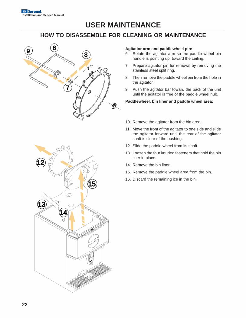
Agitatior arm and paddlewheel pin:6. Rotate the agitator arm so the paddle wheel pin
handle is pointing up, toward the ceiling.
7. Prepare agitator pin for removal by removing thestainless steel split ring.
8. Then remove the paddle wheel pin from the hole inthe agitator.
9. Push the agitator bar toward the back of the unituntil the agitator is free of the paddle wheel hub.
Paddlewheel, bin liner and paddle wheel area:
USER MAINTENANCEHOW TO DISASSEMBLE FOR CLEANING OR MAINTENANCE
10. Remove the agitator from the bin area.
11. Move the front of the agitator to one side and slidethe agitator forward until the rear of the agitatorshaft is clear of the bushing.
12. Slide the paddle wheel from its shaft.
13. Loosen the four knurled fasteners that hold the binliner in place.
14. Remove the bin liner.
15. Remove the paddle wheel area from the bin.
16. Discard the remaining ice in the bin.
23
Installation and Service Manual
PLUMBINGPLUMBING
DIAGRAMDIAGRAM
PUSH FOR ICE
PUSH FOR ICE
1
4
3 2
PPLLUUMMBBIINNGG
DDIIAAGGRRAAMM
PPUUSSHH FFOORR IICCEE
56
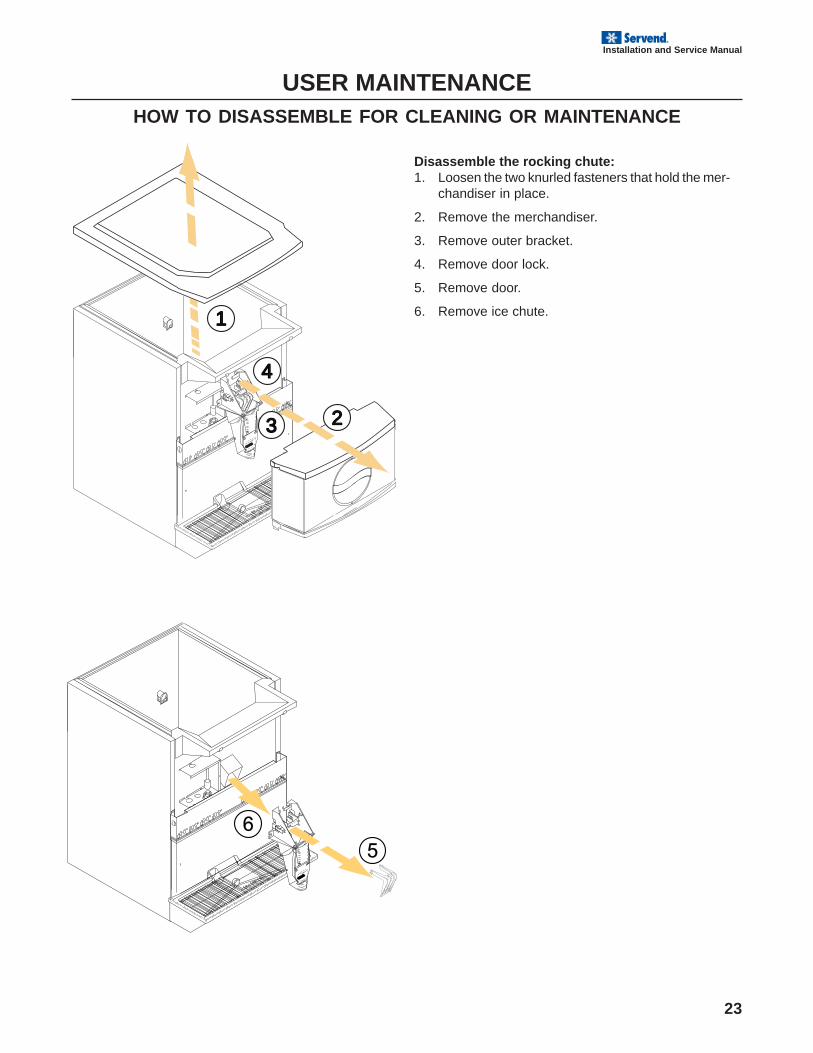
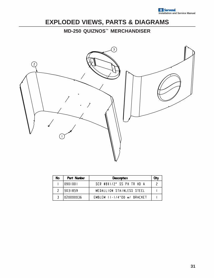
Disassemble the rocking chute:1. Loosen the two knurled fasteners that hold the mer-
chandiser in place.
2. Remove the merchandiser.
3. Remove outer bracket.
4. Remove door lock.
5. Remove door.
6. Remove ice chute.
USER MAINTENANCEHOW TO DISASSEMBLE FOR CLEANING OR MAINTENANCE
24
Installation and Service Manual
USER MAINTENANCEDAILY CLEANING
All cleaning must meet your local health department regulations. The following cleaning instructions areprovided as a guide.
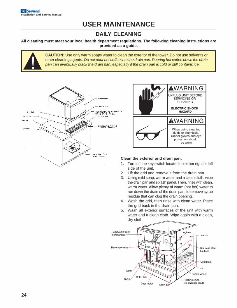
Clean the exterior and drain pan:1. Turn off the key switch located on either right or left
side of the unit.2. Lift the grid and remove it from the drain pan.3. Using mild soap, warm water and a clean cloth, wipe
the drain pan and splash panel. Then, rinse with clean,warm water. Allow plenty of warm (not hot) water torun down the drain of the drain pan, to remove syrupresidue that can clog the drain opening.
4. Wash the grid, then rinse with clean water. Placethe grid back in the drain pan.
5. Wash all exterior surfaces of the unit with warmwater and a clean cloth. Wipe again with a clean,dry cloth.
CAUTION: Use only warm soapy water to clean the exterior of the tower. Do not use solvents orother cleaning agents. Do not pour hot coffee into the drain pan. Pouring hot coffee down the drainpan can eventually crack the drain pan, especially if the drain pan is cold or still contains ice.
Stainless steelbin liner
Cold plate
Ice
Paddle wheel
Rocking chute ice dispense chute
Drain panGear motor
Cold plateSyrup
Water
Beverage valve
Removable frontmerchandiser Ice bin
Agitator
25
Installation and Service Manual
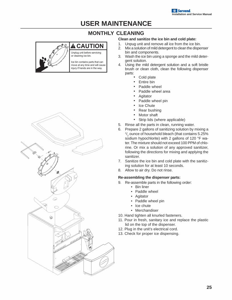
Clean and sanitize the ice bin and cold plate:1. Unpug unit and remove all ice from the ice bin.2. Mix a solution of mild detergent to clean the dispenser
bin and components.3. Wash the ice bin using a sponge and the mild deter-
gent solution.4. Using the mild detergent solution and a soft bristle
brush or clean cloth, clean the following dispenserparts:
• Cold plate• Entire bin• Paddle wheel• Paddle wheel area• Agitator• Paddle wheel pin• Ice Chute• Rear bushing• Motor shaft• Strip lids (where applicable)
5. Rinse all the parts in clean, running water.6. Prepare 2 gallons of sanitizing solution by mixing a
1/2 ounce of household bleach (that contains 5.25%
sodium hypochlorite) with 2 gallons of 120 °F wa-ter. The mixture should not exceed 100 PPM of chlo-rine. Or mix a solution of any approved sanitizer,following the directions for mixing and applying thesanitizer.
7. Sanitize the ice bin and cold plate with the sanitiz-ing solution for at least 10 seconds.
8. Allow to air dry. Do not rinse.
Re-assembling the dispenser parts:9. Re-assemble parts in the following order:
• Bin liner• Paddle wheel• Agitator• Paddle wheel pin• Ice chute• Merchandiser
10. Hand tighten all knurled fasteners.11. Pour in fresh, sanitary ice and replace the plastic
lid on the top of the dispenser.12. Plug in the unit’s electrical cord.13. Check for proper ice dispensing.
USER MAINTENANCEMONTHLY CLEANING
PLUMBINGPLUMBING
DIAGRAMDIAGRAM
PUSH FOR ICE
PUSH FOR ICE
26
Installation and Service Manual
USER MAINTENANCEBEVERAGE SYSTEM CLEANING
Sanitize the beverage system at initial start-up as well as regularly scheduled cleanings. The drain pan must be inplace under soda valves, to carry away detergent and sanitizing agents that will be flushed through valves.
BAG-IN-BOX SYSTEMThe procedure below is for the sanitation of one syrup circuit at a time. Repeat to sanitize additional circuits.
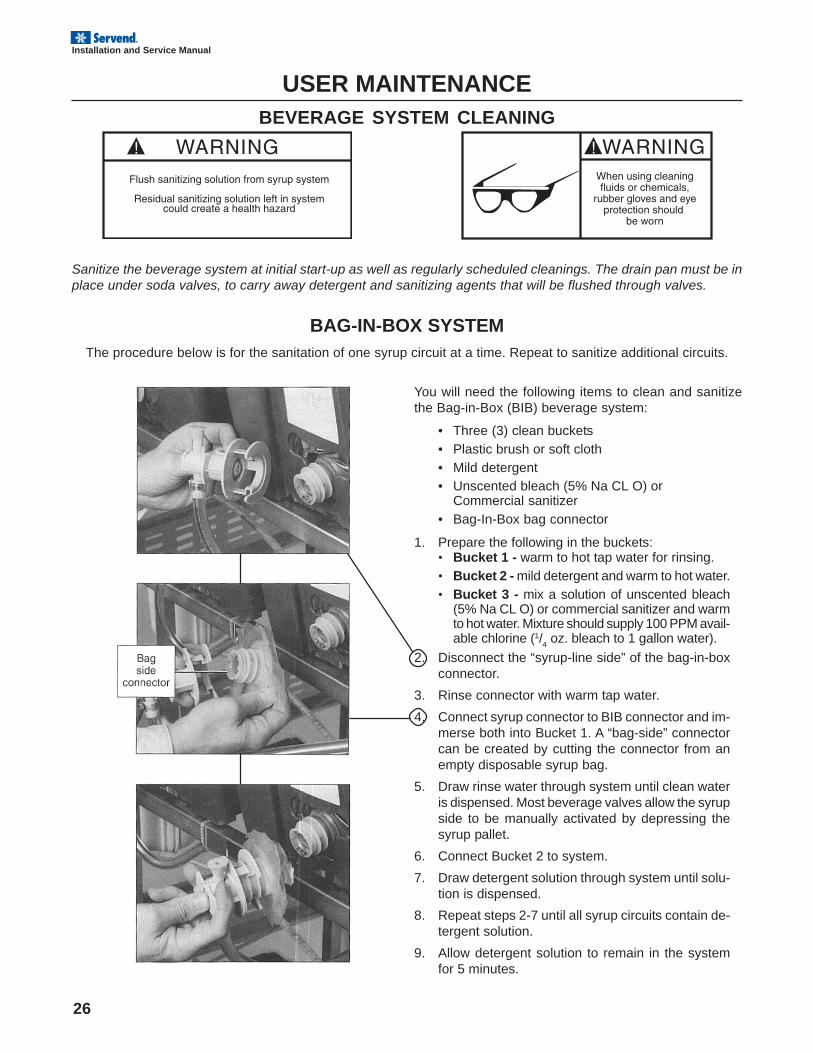
You will need the following items to clean and sanitizethe Bag-in-Box (BIB) beverage system:
• Three (3) clean buckets• Plastic brush or soft cloth• Mild detergent• Unscented bleach (5% Na CL O) or
Commercial sanitizer• Bag-In-Box bag connector
1. Prepare the following in the buckets:• Bucket 1 - warm to hot tap water for rinsing.• Bucket 2 - mild detergent and warm to hot water.• Bucket 3 - mix a solution of unscented bleach
(5% Na CL O) or commercial sanitizer and warmto hot water. Mixture should supply 100 PPM avail-able chlorine (1/
4 oz. bleach to 1 gallon water).
2. Disconnect the “syrup-line side” of the bag-in-boxconnector.
3. Rinse connector with warm tap water.
4. Connect syrup connector to BIB connector and im-merse both into Bucket 1. A “bag-side” connectorcan be created by cutting the connector from anempty disposable syrup bag.
5. Draw rinse water through system until clean wateris dispensed. Most beverage valves allow the syrupside to be manually activated by depressing thesyrup pallet.
6. Connect Bucket 2 to system.
7. Draw detergent solution through system until solu-tion is dispensed.
8. Repeat steps 2-7 until all syrup circuits contain de-tergent solution.
9. Allow detergent solution to remain in the systemfor 5 minutes.
27
Installation and Service Manual
USER MAINTENANCEBAG-IN-BOX SYSTEM
10. Connect Bucket 3 to system.
11. Draw sanitizing solution through system until solu-tion is dispensed.
12. Repeat step 11 until all syrup circuits contain sani-tizer solution.
13. Allow sanitizer solution to remain in system for 15minutes.
14. Remove nozzles and diffusers from beverage valves.
15. Scrub nozzles, diffusers and all removable valveparts (except electrical parts) with a plastic brushor a soft cloth and the detergent solution.
16. Soak nozzles, diffusers and removable valve parts(except electrical parts) in sanitizer for 15 minutes.
17. Replace nozzles, diffusers and valve parts.
18. Connect Bucket 1 to system.
19. Draw rinse water through system until no presenceof sanitizer is detected.
20. Attach syrup connectors to BIB’s.
21. Draw syrup through system until only syrup is dis-pensed.
22. Discard first 2 drinks.
PREVENTATIVE MAINTENANCEThere is little preventative maintenance needed with your Servend dispenser. Following the guidelines below will
assist in trouble free operation.
1. Conduct daily cleaning of the machine.
2. Perform monthly cleaning of the machine.
3. Perform periodic cleaning and sanitizing of bever-age system.
4. Do not overfill the dispenser bin with ice.
5. Do not allow the dispenser to sit for prolonged pe-riods of non use with ice in the bin.
6. Most ice dispenser service problems are causedby low usage of the ice dispenser.
7. Do not store more than one day’s supply of ice.
Possible excess ice storage reasons:• Storage capacity exceeds daily requirements.• Low demand during the off season.• Dispenser oversized with future growth in mind.
Lower ice storage to meet one day’s needs. If you manu-ally fill ice, fill only with the appropriate amount of ice.Fill the dispenser with fresh ice each morning. Do not fillthe dispenser at night just before shut down. Ice cubescan freeze together if not dispensed.
28
Installation and Service Manual
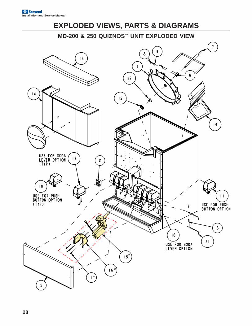
EXPLODED VIEWS, PARTS & DIAGRAMSMD-200 & 250 QUIZNOS™ UNIT EXPLODED VIEW
29
Installation and Service Manual
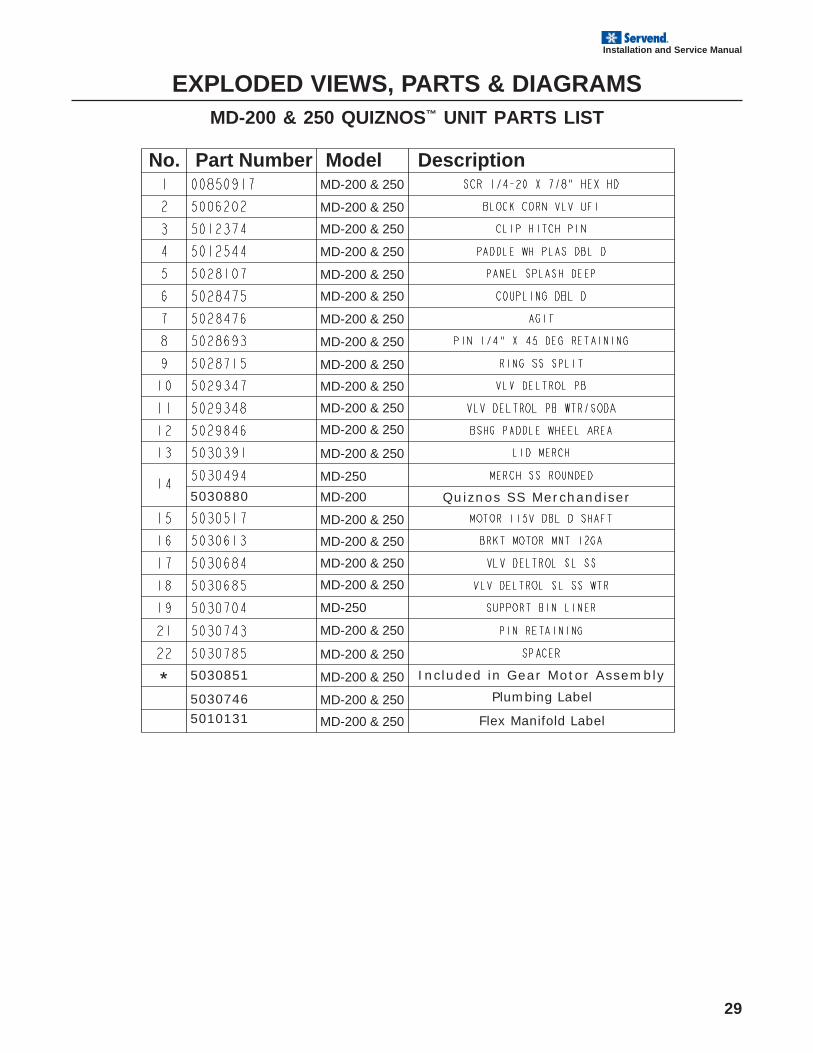
EXPLODED VIEWS, PARTS & DIAGRAMSMD-200 & 250 QUIZNOS™ UNIT PARTS LIST
5030851 Included in Gear Motor Assembly
5030880 Quiznos SS Merchandiser
5030746 Plumbing Label
5010131 Flex Manifold Label
No.�Part Number�Model� DescriptionMD-200 & 250
MD-200 & 250
MD-200 & 250
MD-200 & 250
MD-200 & 250
MD-200 & 250
MD-200 & 250
MD-200 & 250
MD-200 & 250
MD-200 & 250
MD-200 & 250
MD-200 & 250
MD-200 & 250
MD-200 & 250
MD-200 & 250
MD-200 & 250
MD-200 & 250
MD-200 & 250
MD-200 & 250
MD-200 & 250
MD-200 & 250
MD-200 & 250
MD-250
MD-250
MD-200
30
Installation and Service Manual
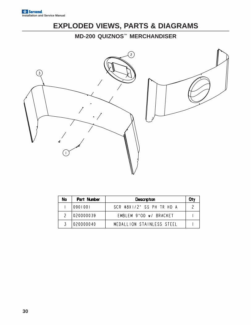
EXPLODED VIEWS, PARTS & DIAGRAMSMD-200 QUIZNOS™ MERCHANDISER
31
Installation and Service Manual
EXPLODED VIEWS, PARTS & DIAGRAMSMD-250 QUIZNOS™ MERCHANDISER
32
Installation and Service Manual
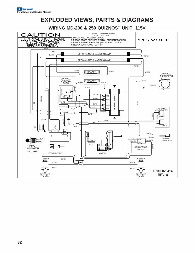
EXPLODED VIEWS, PARTS & DIAGRAMSWIRING MD-200 & 250 QUIZNOS™ UNIT 115V
PUSH
TO RESET TRANSFORMER:(115 VOLT UNITS ONLY)
1. DISCONNECT POWER SUPPLY. 2. PRESS RESET BREAKER SWITCH ON TRANSFORMER.
4. RECONNECT POWER SUPPLY. 3. REPLACE MERCHANDISER (FRONT ENCLOSURE).
BEFORE SERVICINGDISCONNECT POWER
ELECTRICAL SHOCK HAZARD
POWER CORD
EMPTY LIGHTOPTIONAL
CAUTIONS
TA
RT
ER
LIG
HT
TIMERAGITATIONOPTIONAL
KEYSWITCHVALVE
OPTIONALSWITCH
ICE DISPENSE
BALLAST
VALVESBEVERAGE
MOTOR
TR
AN
SF
OR
ME
R
REV. 0
G
OPTIONAL MERCHANDISING LAMP
BALLAST
OPTIONAL MERCHANDISING LAMP
LIG
HT
ST
AR
TE
R
VALVESBEVERAGE
THERMOSTAT
ORANGE
BLUE
OPTIONAL
ORANGE
BLUE
YELLOW
BLA
CK
BLACK
BLACK
BLACK
WHITE
WHITE
WHITE
BLACK
BLACKBLACK
YE
LLOW
PN#:5029414
PURPLE
WHITE
WHITE
PURPLE
BLACK
RED
BLACK BLACK
WHITE
BLUE
BLACK
WHITEWHITE
BLACK
BLACK
BLACK
B
PU
RP
LE
RED
BLUE
RED
PUSH
OPTIONAL
GR
AY
AUDIBLE ALARM
BLU
E
TIMER
3
1
2
BUZZER
BLU
E
BLACK
BLUE
W
WHITE
115 VOLT
2
5
3
1
4
NO
NCCOMMON
IN
OUT
LINE
LOAD
LOAD
LINEWHITE
BLACK
WH
ITE
33
Installation and Service Manual
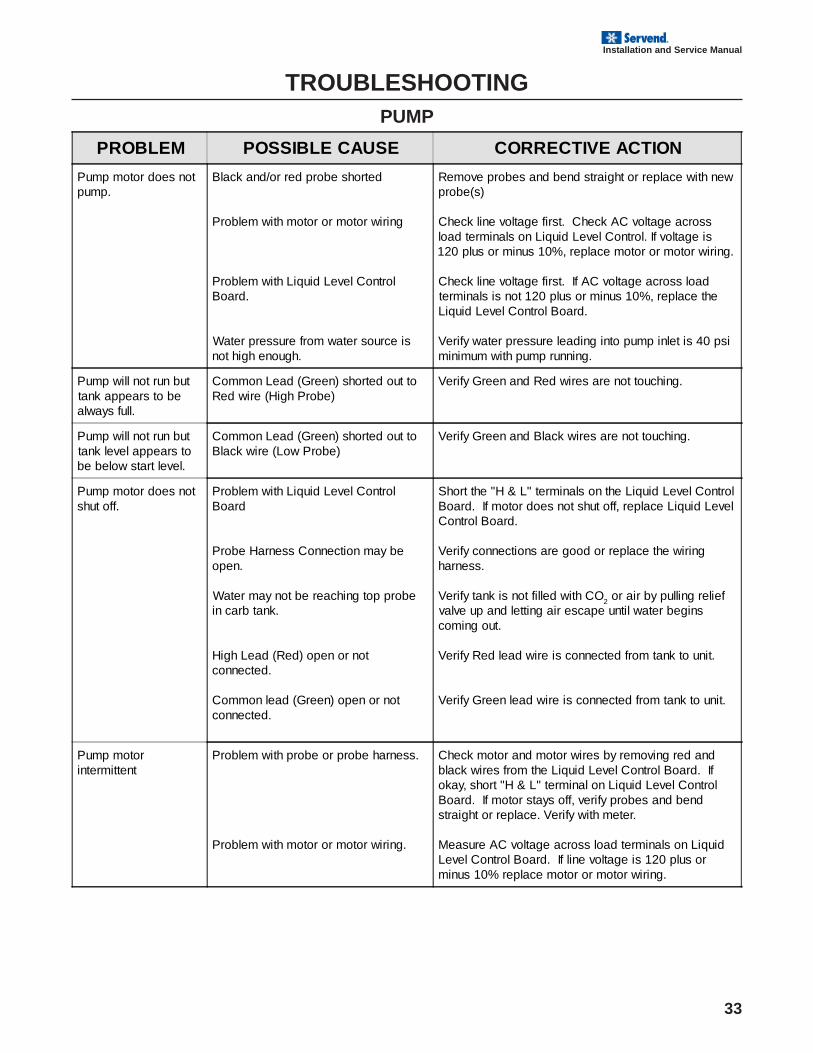
TROUBLESHOOTINGPUMP
PROBLEM POSSIBLE CAUSE CORRECTIVE ACTION
Pump motor does notpump.
Black and/or red probe shorted
Problem with motor or motor wiring
Problem with Liquid Level ControlBoard.
Water pressure from water source isnot high enough.
Remove probes and bend straight or replace with newprobe(s)
Check line voltage first. Check AC voltage acrossload terminals on Liquid Level Control. If voltage is120 plus or minus 10%, replace motor or motor wiring.
Check line voltage first. If AC voltage across loadterminals is not 120 plus or minus 10%, replace theLiquid Level Control Board.
Verify water pressure leading into pump inlet is 40 psiminimum with pump running.
Pump will not run buttank appears to bealways full.
Common Lead (Green) shorted out toRed wire (High Probe)
Verify Green and Red wires are not touching.
Pump will not run buttank level appears tobe below start level.
Common Lead (Green) shorted out toBlack wire (Low Probe)
Verify Green and Black wires are not touching.
Pump motor does notshut off.
Problem with Liquid Level ControlBoard
Probe Harness Connection may beopen.
Water may not be reaching top probein carb tank.
High Lead (Red) open or notconnected.
Common lead (Green) open or notconnected.
Short the "H & L" terminals on the Liquid Level ControlBoard. If motor does not shut off, replace Liquid LevelControl Board.
Verify connections are good or replace the wiringharness.
Verify tank is not filled with CO2 or air by pulling reliefvalve up and letting air escape until water beginscoming out.
Verify Red lead wire is connected from tank to unit.
Verify Green lead wire is connected from tank to unit.
Pump motorintermittent
Problem with probe or probe harness.
Problem with motor or motor wiring.
Check motor and motor wires by removing red andblack wires from the Liquid Level Control Board. Ifokay, short "H & L" terminal on Liquid Level ControlBoard. If motor stays off, verify probes and bendstraight or replace. Verify with meter.
Measure AC voltage across load terminals on LiquidLevel Control Board. If line voltage is 120 plus orminus 10% replace motor or motor wiring.
34
Installation and Service Manual
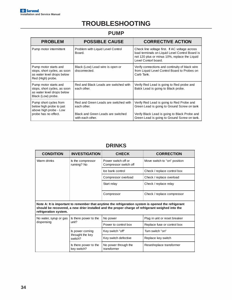
TROUBLESHOOTINGPUMP
PROBLEM POSSIBLE CAUSE CORRECTIVE ACTION
Pump motor intermittent Problem with Liquid Level ControlBoard.
Check line voltage first. If AC voltage acrossload terminals on Liquid Level Control Board isnot 120 plus or minus 10%, replace the LiquidLevel Contorl board.
Pump motor starts andstops, short cycles, as soonas water level drops belowRed (High) probe.
Black (Low) Lead wire is open ordisconnected.
Verify connections and continuity of black wirefrom Liquid Level Control Board to Probes onCarb Tank.
Pump motor starts andstops, short cycles, as soonas water level drops belowBlack (Low) probe.
Red and Black Leads are switched witheach other.
Verify Red Lead is going to Red probe andBalck Lead is going to Black probe.
Pump short cycles frombelow high probe to justabove high probe - Lowprobe has no effect.
Red and Green Leads are switched witheach other.
Black and Green Leads are switchedwith each other.
Verify Red Lead is going to Red Probe andGreen Lead is going to Ground Screw on tank
Verify Black Lead is going to Black Probe andGreen Lead is going to Ground Screw on tank.
CONDITION INVESTIGATION CHECK CORRECTION
Warm drinks Is the compressorrunning? No
Power switch off orCompressor switch off
Move switch to "on" position
Ice bank control Check / replace control box
Compressor overload Check / replace overload
Start relay Check / replace relay
Compressor Check / replace compressor
Note A: It is important to remember that anytime the refrigeration system is opened the refrigerantshould be recovered, a new drier installed and the proper charge of refrigerant weighed into therefrigeration system.
No water, syrup or gasdispensing
Is there power to theunit?
No power Plug in unit or reset breaker
Power to control box Replace fuse or control box
Is power comingthrought the keyswitch?
Key switch "off" Turn switch "on"
Key switch defective Replace key switch
Is there power to thekey switch?
No power through thetransformer
Reset/replace transformer
DRINKS
35
Installation and Service Manual
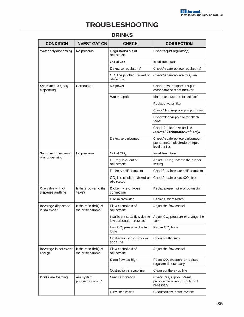
TROUBLESHOOTINGDRINKS
CONDITION INVESTIGATION CHECK CORRECTION
Water only dispensing No pressure Regulator(s) out ofadjustment
Check/adjust regulator(s)
Out of CO2 Install fresh tank
Defective regulator(s) Check/repair/replace regulator(s)
CO2 line pinched, kinked or
obstructedCheck/repair/replace CO
2 line
Syrup and CO2 onlydispensing
Carbonator No power Check power supply. Plug incarbonator or reset breaker.
Water supply Make sure water is turned "on"
Replace water filter
Check/clean/replace pump strainer
Check/clean/repair water checkvalve
Check for frozen water line.Internal Carbonator unit only.
Defective carbonator Check/repair/replace carbonatorpump, motor, electrode or liquidlevel control.
Syrup and plain wateronly dispensing
No pressure Out of CO2
Install fresh tank
HP regulator out ofadjustment
Adjust HP regulator to the propersetting
Defective HP regulator Check/repair/replace HP regulator
CO2 line pinched, kinked orobstructed
Check/repair/replaceCO2 line
One valve will notdispense anything
Is there power to thevalve?
Broken wire or looseconnection
Replace/repair wire or connector
Bad microswitch Replace microswitch
Beverage dispensedis too sweet
Is the ratio (brix) ofthe drink correct?
Flow control out ofadjustment
Adjust the flow control
Insufficient soda flow due tolow carbonator pressure
Adjust CO2 pressure or change thetank
Low CO2 pressure due toleaks
Repair CO2 leaks
Obstruction in the water orsoda line
Clean out the lines
Beverage is not sweetenough
Is the ratio (brix) ofthe drink correct?
Flow control out ofadjustment
Adjust the flow control
Soda flow too high Reset CO2 pressure or replaceregulator if necessary
Obstruction in syrup line Clean out the syrup line
Drinks are foaming Are systempressures correct?
Over carbonation Check CO2 supply. Resetpressure or replace regulator ifnecessary
Dirty lines/valves Clean/sanitize entire system
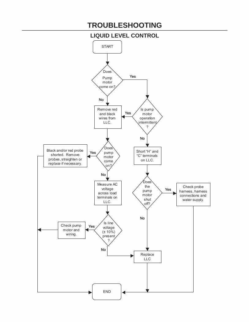
TROUBLESHOOTINGLIQUID LEVEL CONTROL
END
START
Does
Pump motor
come on?
Remove red and black wires from
LLC.
Is pump motor
operation intermittent
?
Does pump motor come on?
Black and/or red probe shorted. Remove
probes, straighten or replace if necessary.
Short “H” and “C” terminals
on LLC.
Does the
pump motor shut off?
Measure AC voltage
across load terminals on
LLC.
Check pump motor and
wiring.
Check probe harness, harness connections and
water supply.
Is line voltage (± 10%) present
?
Replace LLC
Yes
No
Yes
Yes
Yes
Yes
No
No
No
No


INDEXB
Back Room Package ............... 17brixing ....................................... 3
C
Carbon Dioxide ......................... 6CAUTION .......................... 18, 25claims ...................................... 15Cleaning .................................... 3CO2 ........................................... 7CO2 monitors ............................ 7
D
damage .............................. 3, 15delivery .............................. 3, 15distributor .................................. 3Drain .......................................... 8ducts ......................................... 8
E
exterior ................................... 24
F
FOREWORD .............................. 3
H
health department ................... 24
I
INSPECTION .............................. 3INSTALLATION8, 9, 10, 11, 12, 13Installation Date ........................ 3Instructions ............................. 24irregularities .............................. 3
L
location ..................................... 8
M
MBE ........................................... 3Model Number ........................... 3modifications ............................. 6Monthly Cleaning .................... 25
O
Operation .................................. 6
P
Power outlet ............................. 8
Q
Qualified Service Personnel ..... 6
R
regulations .............................. 24Relocation ................................. 6return procedures .................... 3
S
SAFETY ............................... 6, 7sanitizing ................................... 7Serial Number ........................... 3service assistance ................... 3Service Personnel .................... 6Shipping .................................... 6Shipping, Storage, Relocation .. 6soapy water ........................... 25solvents .................................. 25start-up ..................................... 6Storage ..................................... 6
T
TROUBLESHOOTING33, 34, 35, 36
U
Unit Inspection ........................ 15UNPACKING .............................. 3
W
Warning .................................... 6WARRANTY INFORMATION ..... 3Water line .................................. 8water-to-syrup ratio. Seebrixing

Manitowoc Beverage Equipment2100 Future Drive Sellersburg, IN 47172-1868Tel: 812.246.7000, 800.367.4233 Fax: 812.246.9922www.manitowocbeverage.com
In accordance with our policy of continuous product development andimprovement, this information is subject to change at any time without notice.
5030765 October 19, 2006 REV6