30” wide 1 and 2 evaporator compact technical training cubers
TRANSCRIPT
30” Wide 1 and 2 Evaporator Compact
CubersTechnical Training
• Models Covered• Components• Installation• Electrical Sequence• Service Diagnosis• Refrigeration System
Presentation TopicsPresentation Topics

CMCM33 -- "CM Cubed""CM Cubed"
• Compact Modular Cubers -overflow drain type– CME256– CME506– CME656– CME806
• Similar technology used in SCE275
• Purge valve drains used in– CME306, CME456, CME686,
CME810, CME1056, CME1356, CME1656, CME1856, CME2006
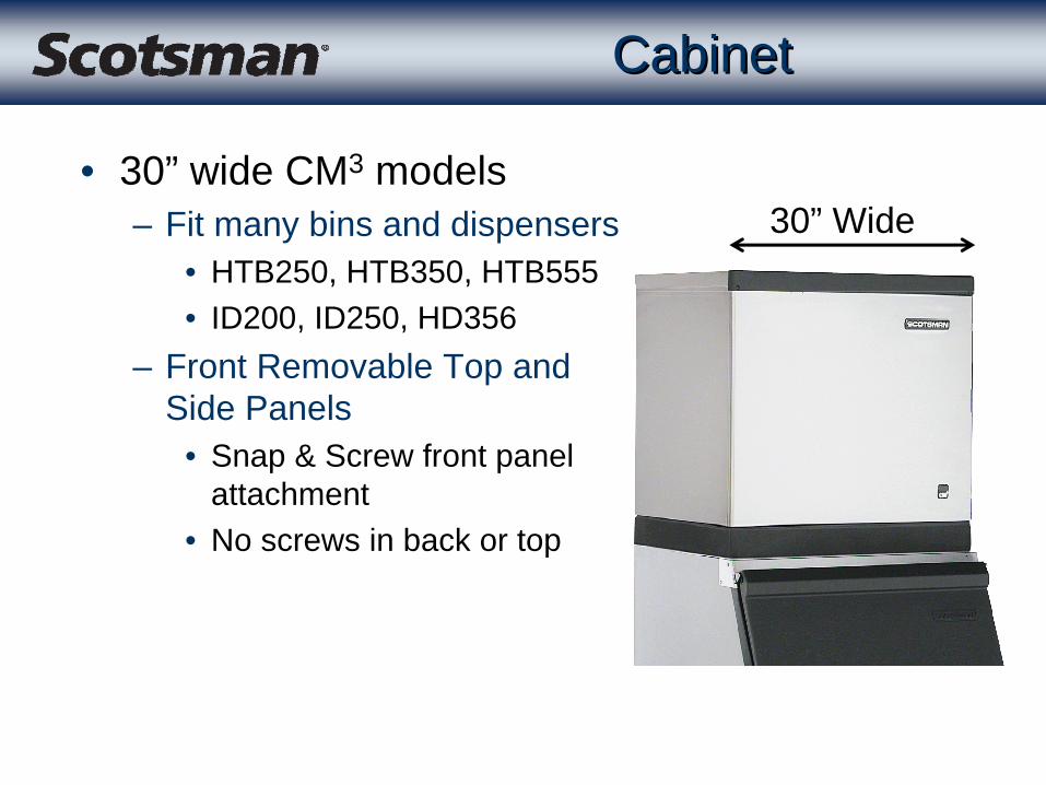
CabinetCabinet
• 30” wide CM3 models– Fit many bins and dispensers
• HTB250, HTB350, HTB555• ID200, ID250, HD356
– Front Removable Top and Side Panels
• Snap & Screw front panel attachment
• No screws in back or top
30” Wide

Front PanelFront Panel
• Removal of front panel provides access to – Controller– Water valve– Water pump
• Evaporator cover behind it provides a– Thermal barrier– Water barrier

AutoIQController
Water LevelSensor
Water Compartment
Front ViewFront View
Disposable Air Filter - one on each side
Hi Voltage Box

Hi Voltage BoxHi Voltage Box
A - C Series Single Phase
D Series & higher use (PTCR) for Single Phase
PTCR

AutoIQ Control SystemAutoIQ Control System
• All electronic, microprocessor controlled• Measures water level for cube size• No altitude or ambient adjustments needed• Freeze up protection• Electric-eye ice sensors & bin control• New Controller in 2002
– Blue box, but same operation as prior black controller
– Last 2 errors can be recalled– Displays EEPROM code at power up– Universal Service Controller - fits all CM3
Control SystemControl System
• Controller collects, stores and uses data to determine:– Pump and fan off time– Freeze times– End of Harvest time– Reservoir flush time– Bin full– Water or Refrigeration errors– Water level/cube size

Control SystemControl System
Water Temperature Sensor Left Bin Control Ice Sensor
AutoIQController
DischargeTemperatureSensor
Water LevelSensor
Right BinControl IceSensor

AutoIQ ControllerAutoIQ Controller
• Adaptive Harvest– Optimizes harvest time
• AutoRestart– After power interruptions– After water interruptions– After long harvest or
freeze • AntiSlush
– First three cycles after restart
• Indicator Lights– Easier diagnostics
AutoIQ ControllerAutoIQ Controller
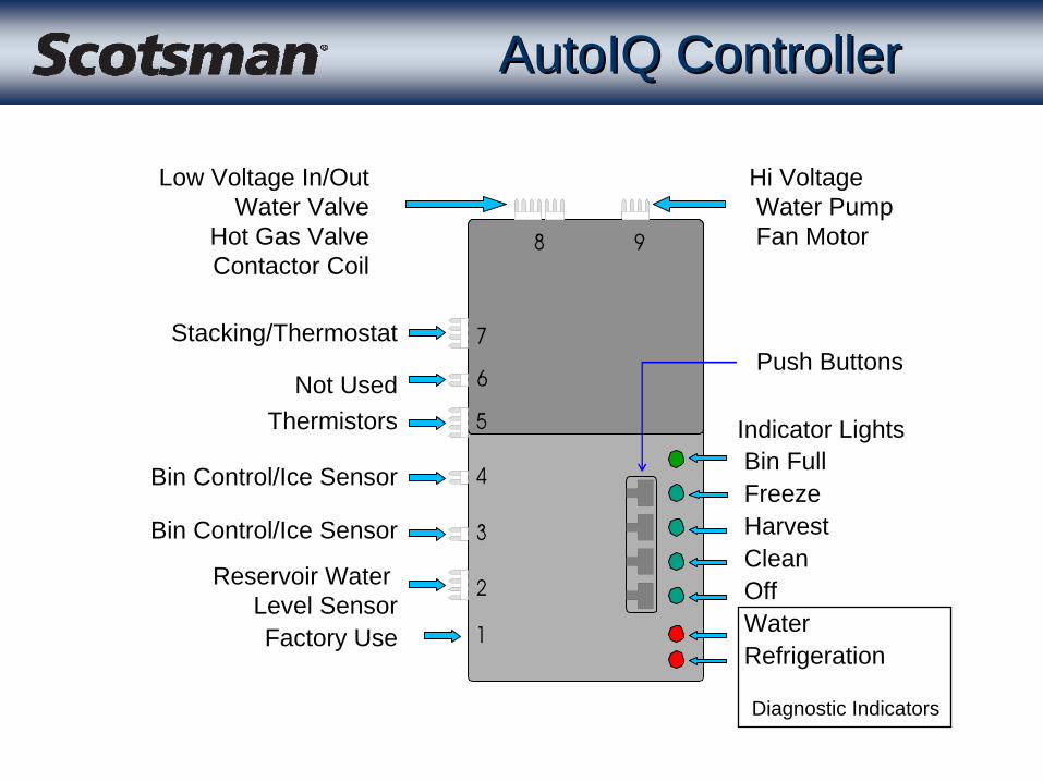
Low Voltage In/OutWater Valve
Hot Gas ValveContactor Coil
Stacking/Thermostat
Not UsedThermistors
Bin Control/Ice Sensor
Bin Control/Ice Sensor
Reservoir Water Level SensorFactory Use
Hi VoltageWater PumpFan Motor
Push Buttons
Indicator LightsBin FullFreezeHarvestCleanOffWater Refrigeration
Diagnostic Indicators

Controls Controls -- Water SystemWater System
• Water enters in harvest thru solenoid valve– Gravity drain overflow
• Uses a standpipe in the reservoir to control maximum water height
• Control system calculates each cycle’s water flow rate and adjusts for it– Benefit: Overflows the same amount of water under
different water flow conditions, which provides an assured amount of rinse water
• Water overflow amount is manually adjustable for variations in water quality
Controls Controls -- Water SystemWater System
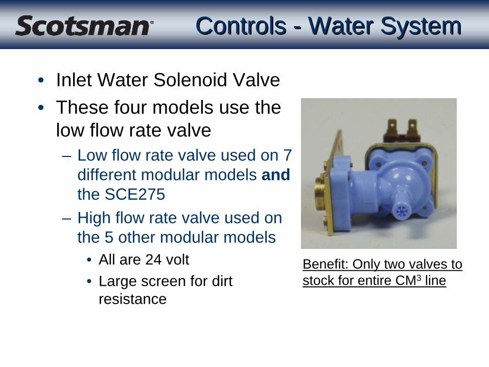
• Inlet Water Solenoid Valve• These four models use the
low flow rate valve– Low flow rate valve used on 7
different modular models and the SCE275
– High flow rate valve used on the 5 other modular models
• All are 24 volt• Large screen for dirt
resistance
Benefit: Only two valves to stock for entire CM3 line
Water SystemWater System
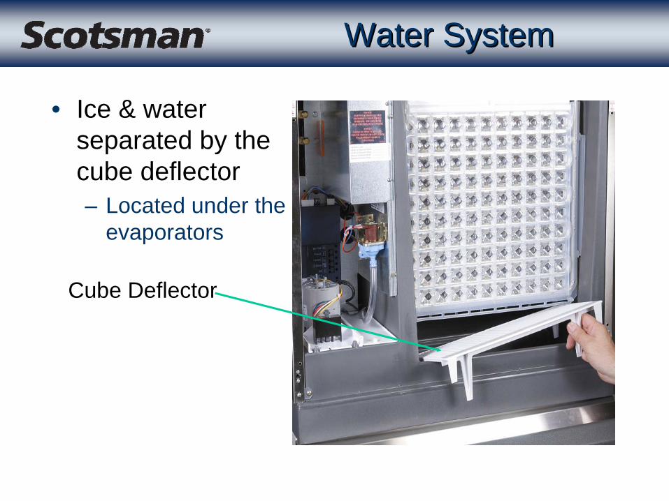
• Ice & water separated by the cube deflector– Located under the
evaporators
Cube Deflector

Cascading ShieldCascading Shield
– The Two Evaporator models have a cascading shield• CME506, CME656 and CME806• Snaps onto tabs molded onto the bin control/ice sensors
Cascading Shield
Tab on Sensor Housing
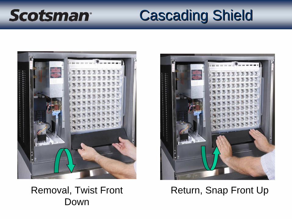
Cascading ShieldCascading Shield
Removal, Twist Front Down
Return, Snap Front Up
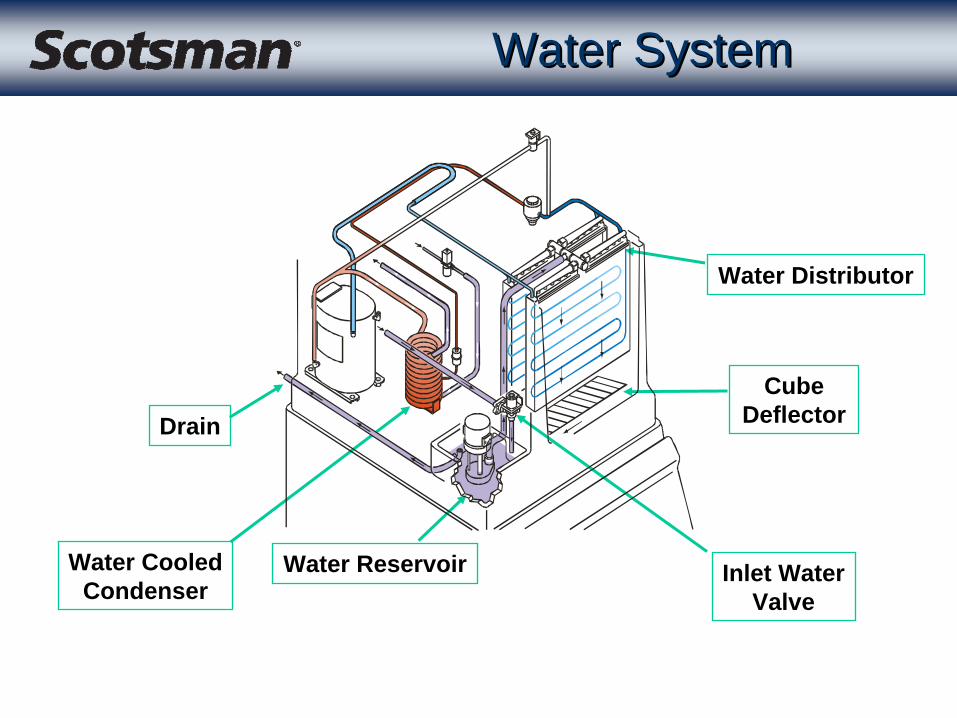
Water SystemWater System
Water Distributor
Cube Deflector
Water ReservoirWater CooledCondenser
Drain
Inlet WaterValve

Water SystemWater System
Overflow Standpipe
Water Level
Pump Discharge Hose
Drain

Water ReservoirWater Reservoir
Water Overflow
Stand Pipe
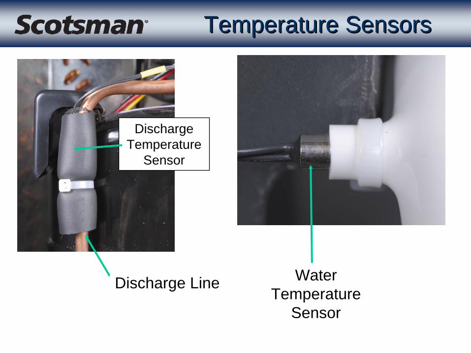
Discharge Temperature
Sensor
Water Temperature
Sensor
Discharge Line
Temperature SensorsTemperature Sensors
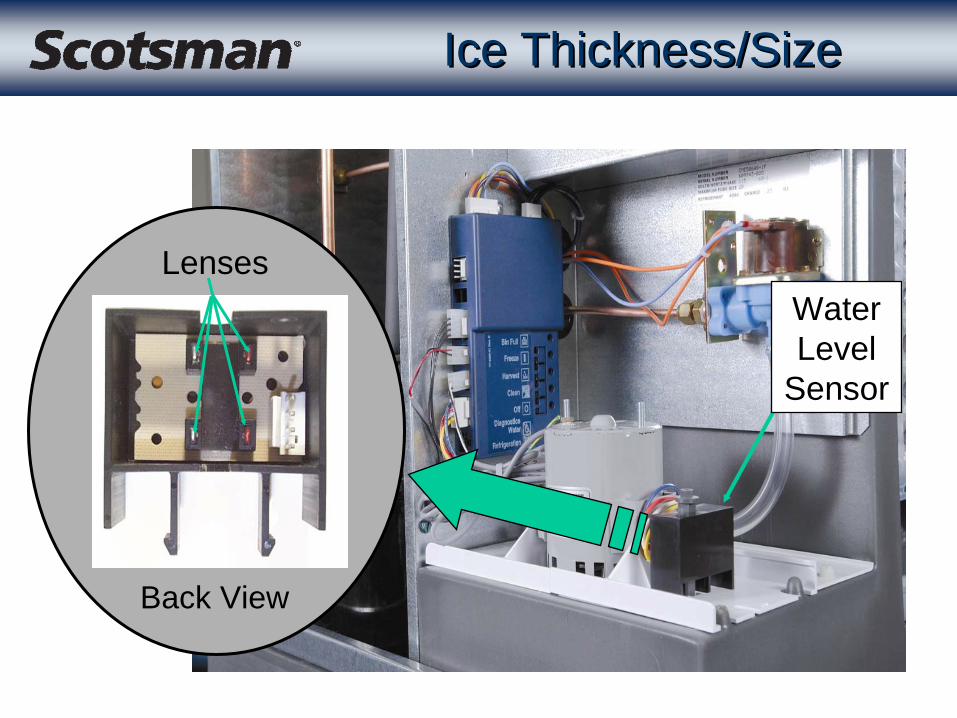
Ice Thickness/SizeIce Thickness/Size
Lenses
Back View
Water Level
Sensor

Bin Control/Ice SensorsBin Control/Ice Sensors
• Uses Photo-Electric Eyes• Located on ends of ice
chute– Emitter on one side– Receiver on the other– Two eyes per side– Creates a “Light Curtain”
Photo-Eye Lenses
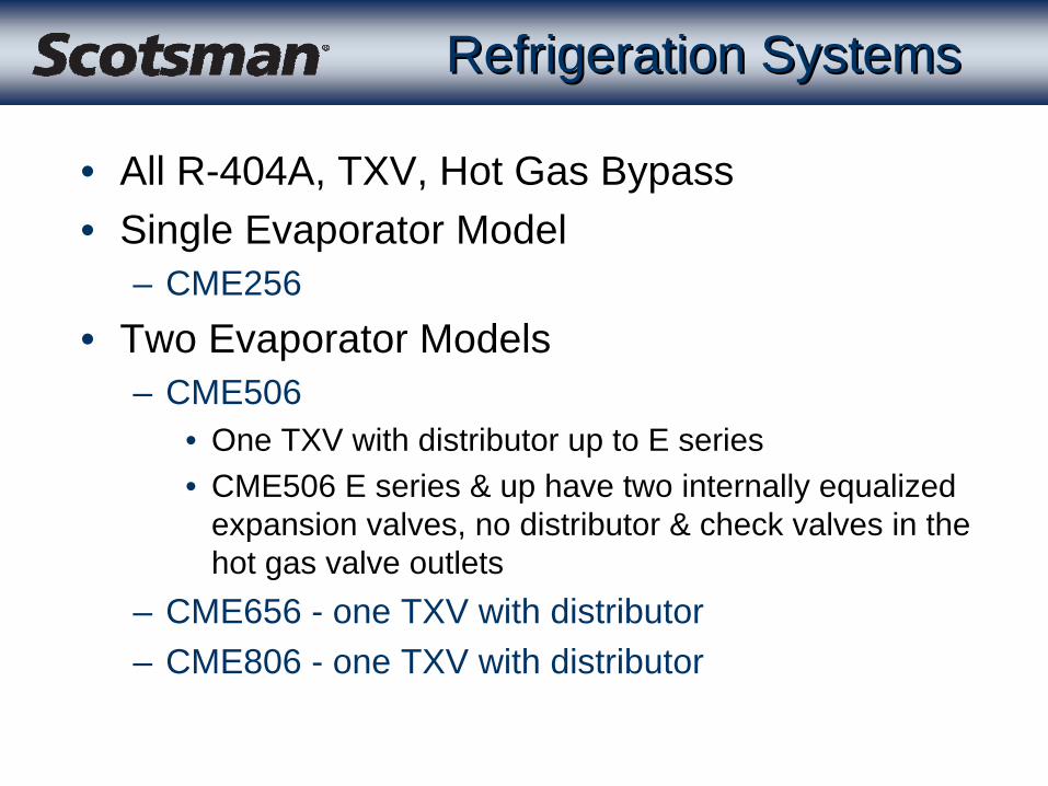
Refrigeration SystemsRefrigeration Systems
• All R-404A, TXV, Hot Gas Bypass• Single Evaporator Model
– CME256• Two Evaporator Models
– CME506• One TXV with distributor up to E series• CME506 E series & up have two internally equalized
expansion valves, no distributor & check valves in the hot gas valve outlets
– CME656 - one TXV with distributor– CME806 - one TXV with distributor

Refrigeration SystemsRefrigeration Systems
• Two Expansion Valve System– Similar to CME456– Internally equalized
valves– Check valves in hot
gas valve outlet to direct refrigerant to single evaporator

Refrigeration SystemsRefrigeration Systems
• Water Cooled Condenser Change– A through E series use
same condenser– F series and up use
different one• Small charge change• Separate service
parts
Refrigeration SystemsRefrigeration Systems
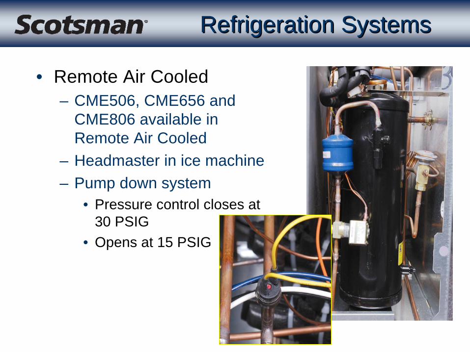
• Remote Air Cooled– CME506, CME656 and
CME806 available in Remote Air Cooled
– Headmaster in ice machine– Pump down system
• Pressure control closes at 30 PSIG
• Opens at 15 PSIG

InstallationInstallation
• Level the unit– Level the bin left to right
• At the canopy– Level the machine front to
back• At the reservoir
• If placing on a dispenser– ID200 or ID250 require
adapter KBT44– IM must be sealed to
adapter– Must install baffle from
adapter
InstallationInstallation
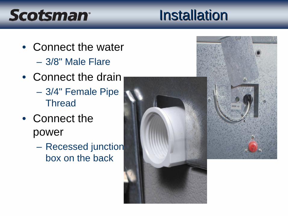
• Connect the water– 3/8" Male Flare
• Connect the drain– 3/4" Female Pipe
Thread• Connect the
power– Recessed junction
box on the back
Installation DetailsInstallation Details
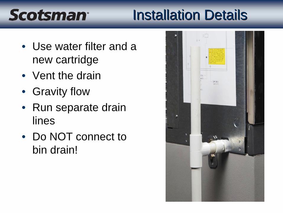
• Use water filter and a new cartridge
• Vent the drain• Gravity flow• Run separate drain
lines• Do NOT connect to
bin drain!

Initial Start UpInitial Start Up
• Remove front panel.– Check for power. All lights on
the controller flash once when power is first connected.
– Blue Controllers blink their red lights for 20 seconds while displaying their EEPROM code
– Blue Controllers then display the Bin Full light and the Off Light. The Bin Full light will go out after a few seconds
– Then the Off light will be ON.
Initial Start UpInitial Start Up
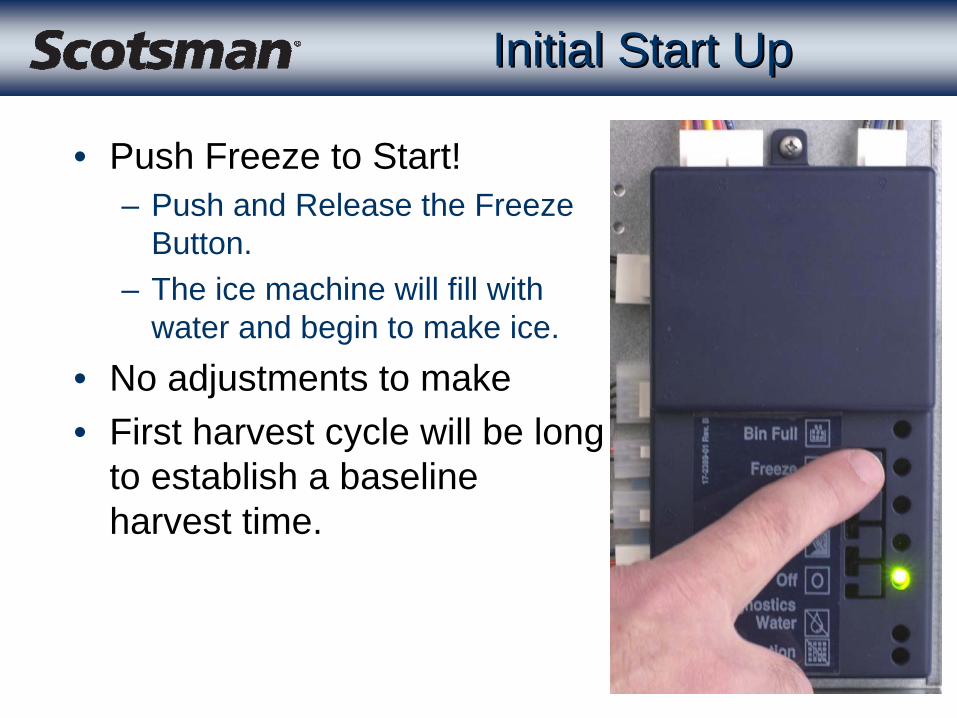
• Push Freeze to Start!– Push and Release the Freeze
Button.– The ice machine will fill with
water and begin to make ice.• No adjustments to make• First harvest cycle will be long
to establish a baseline harvest time.

Electrical Sequence: StartingElectrical Sequence: Starting
• Water valve opens, float rises
• Pump & Compressor start– Reservoir must be full
• 3 minutes into freeze – Discharge temp measured– If less than 1250F., fan
cycles every 30 seconds

Electrical Sequence: Freeze Electrical Sequence: Freeze
• Reservoir water must cool to preset point (38 degrees) in 5 minutes– Controller checks water
and discharge temps.– Checking to see that
refrigeration system is working
– And that inlet water valve is not leaking thru
• If not, will do a check of the discharge temp

Electrical Sequence: FreezeElectrical Sequence: Freeze
• The first 3 cycles have an anti-slush cycle.– When water temp falls
to the set point, the pump switches off for 30 seconds
– Can happen any time within the first 5 minutes of freeze
– Re-fills the reservoir after the pump restarts

Electrical Sequence: FreezeElectrical Sequence: Freeze
• End of Freeze determined by water level– Water Level Determines Cube
Size– In the water level sensor
• Upper electric eye determines the end of the freeze cycle.
• Lower eye determines when the reservoir is full of water.
Upper Eye
Lower Eye

Electrical SequenceElectrical Sequence
• Fan Control - temperature & cycle based– Fan cycles on and off throughout the freeze cycle if
discharge temp is low at the beginning• Maintains discharge pressure - if temp is high fan is
on till the end of the cycle• Old controllers (from 1996) use a fan control switch
(pressure control).– The system controller shuts the fan off just before
the end of the freeze cycle. • Fan off time varies between 0 and 60 seconds - based
on the discharge line temp at the end of the freeze cycle.
– The fan is off during Harvest.

Harvest TimeHarvest Time
• ANY Cube Ice Machine’s Harvest time will vary because of changes in:– Ambient Temperature– Incoming Water Temperature– Condition of Water System - how much scale
• CM3 Harvest time adapts to changing conditions– Bin control / ice sensors “see” ice falling.– The first harvest cycle after start up will be 5 minutes
• Determines the base line harvest time. – After that the controller adjusts the harvest cycle
time to match the requirements for harvest.

Harvest Cycle TimingHarvest Cycle Timing
• Controller begins timing harvest• Ice falling interrupts the signal from the ice sensor
emitter to the receiver– The time of that interrupt is recorded by the controller– The last time the controller receives an interrupt signal
is saved as the cube release time– Extra time is calculated from the actual cube release
timeMeasured Cube Release Time + Calculated Extra Time = Harvest
Time

Harvest CycleHarvest Cycle
• All controllers– AC Fan is off – Pump is off for 40 seconds– Water valve opens
• If harvest is very long– Pump is off after 8 minutes of harvest
• If bin fills early in harvest– Pump is off when bin is full, but harvest continues
Water FillWater Fill
• Water re-fills during Harvest– Controller measures flow rate
• Time between start and completion of fill is measured every time
– Always adds and flushes the same amount of water
– Amount of water & rinse is adjustable– Will shut down if does not fill fast enough or at all
• Will try to restart every 20 minutes
End of HarvestEnd of Harvest
• Harvest time expired– Return to Freeze– Bin Full - when bin controls are blocked for 5 - 20
seconds• Off if thermostat connected to controller terminal 7 is
closed
• If ice wasn’t “seen” by the bin controls– Will make one more cycle
• If it happens again, unit shuts down

RestartsRestarts
• Electrical Power Interruption– Automatic restart
• Open hot gas valve for 20 seconds• Open water valve to fill reservoir• Start Pump• Start compressor, freeze for 30 seconds• Harvest for 4 minutes• Freeze light will be blinking• If bin is not full will automatically start a new freeze cycle
• Blue controllers manual harvest must be complete or pushing freeze will trigger this restart sequence

RestartsRestarts
• Water supply interruption– Automatic shut off and restart
• Shuts off if float does not rise enough during Harvest• 130 second time limit to fill reservoir
– Controller checks for water by opening the inlet water valve every 20 minutes
• Will restart if float rises far enough to break beam in water level sensor

Ice & EvaporatorIce & Evaporator
• Ice Formation– Freezes from the bottom
of the evaporator(s) to the top.
– 3.25 to 3.5 LB. per evaporator per cycle.
– Harvests as vertical strips - not individual cubes.
– Cubes from the strips break up when falling down.

Ice Level ControlIce Level Control
• What controls ice making?– There are two methods of on-off control - ice sensors
or bin thermostat– At the base of the cube chute is a set of electric eyes
- the ice sensors. – When ice has filled the bin, ice will be between the
ice sensors. The bin full light will blink and then be on.
• Thermostat sometimes used - accessory kit can add it• Thermostat must close on temperature fall• Plugs onto terminal 7 on the controller• Controls bin full light too
Ice Level ControlIce Level Control
• Control System– When the ice sensors have been "blocked" for more
than 20 seconds (5 with the blue controller), the Bin Full Light will glow steadily and:
• The machine will shut down at the end of the next harvest cycle.
• It can not restart until 4 minutes have passed.
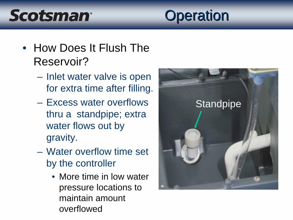
OperationOperation
• How Does It Flush The Reservoir?– Inlet water valve is open
for extra time after filling.– Excess water overflows
thru a standpipe; extra water flows out by gravity.
– Water overflow time set by the controller
• More time in low water pressure locations to maintain amount overflowed
Standpipe

OperationOperation
• Is the amount of water rinse adjustable?– Yes it is, the 5 levels are:
• Maximum• Heavy• Standard - the factory setting• Moderate • Minimum

CleaningCleaning
Pull Here to Remove
Photo-Eyes
Place Ends of Photo-Eyes in Reservoir for Cleaning

Cleaning & SanitizingCleaning & Sanitizing
• Water System Cleaning– Push and release the clean button.
• The cycle begins by re-starting the pump.• Pour in the cleaner; circulate for as long as needed -
10 minutes or so.• Push the clean button again to flush the residual
cleaner for about 20 minutes. • Push the Freeze button to resume making ice.

CleaningCleaning

General Service General Service
Refrigeration10%
Electrical20%
Water70%
• Remember the Recipe for ICE!– Water issues most common
• And Start with a CLEAN MACHINE!

Unit is Off, Why?Unit is Off, Why?
• Check Controller– No Power to unit
• No lights ON.– Transformer failed
• No lights ON.– Loose wire at Controller
• No lights ON.– Unit is switched to OFF
• Off light is ON.

Last Error RecallLast Error Recall
• If the controller has been reset, and is blue, the last two error codes can still be recalled– Stop unit by holding the Off
button in for 3 seconds– Push and hold Off button again
for 3 seconds until the green lights come on
– Push and release the Harvest button to see the last error
– Push and release the Harvest button again to the second to last error - Bin Full light will glow
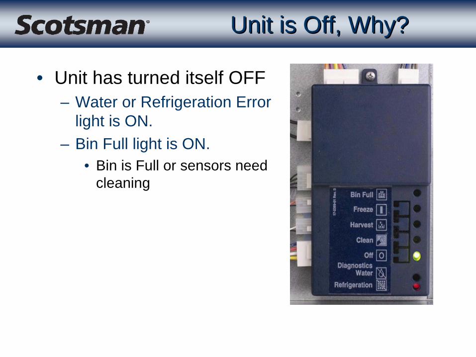
Unit is Off, Why?Unit is Off, Why?
• Unit has turned itself OFF– Water or Refrigeration Error
light is ON.– Bin Full light is ON.
• Bin is Full or sensors need cleaning
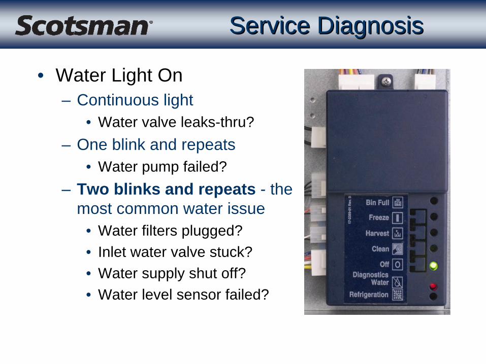
Service DiagnosisService Diagnosis
• Water Light On– Continuous light
• Water valve leaks-thru?– One blink and repeats
• Water pump failed?– Two blinks and repeats - the
most common water issue• Water filters plugged?• Inlet water valve stuck?• Water supply shut off?• Water level sensor failed?

Service DiagnosisService Diagnosis
• Water fill problems– Check water filters– Check levelness of machine– Check standpipe measurement
• Reset machine – If water error repeats
• Check harness to controller from water level sensor• Replace the water level sensor or harness

Standpipe Standpipe
• Measurement– Height is factory set,
should not need adjustment, but..
– Correct height is 2 and 5 eighths inches from the top of the standpipe adjustment nut to the top of the reservoir wall
– Set measuring device first, then adjust nut
Adjustment Nut

Water Sensor DiagnosticsWater Sensor Diagnostics
• Check voltage w/ DC VM– Controller must have
power and be “alive”– a) Unplug harness from
position 2, check voltage at top and bottom pins
– b) Reconnect, check voltage again
– Negative on yellow, positive on white, move float. Voltage should change
– Positive on red, move float
Black Blue
a) Top to Bottom 24 to 30 .5 to 2
b) Top to bottom 2 to 3.5 .4 to 2
White to Yellow, blocked
5 5
White to Yellow, unblocked
<1 Less than when blocked
Red to Yellow, blocked
5 5
Red to Yellow, unblocked
<1 Less than when blocked
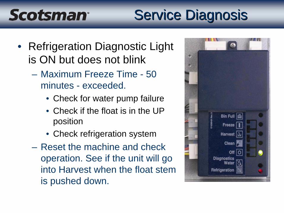
Service DiagnosisService Diagnosis
• Refrigeration Diagnostic Light is ON but does not blink– Maximum Freeze Time - 50
minutes - exceeded.• Check for water pump failure• Check if the float is in the UP
position• Check refrigeration system
– Reset the machine and check operation. See if the unit will go into Harvest when the float stem is pushed down.

Service DiagnosisService Diagnosis
• Refrigeration Light ON but does not blink– Maximum Freeze Time
Exceeded– Water cooled or Remote
tripped the Hi Pressure Cut Out.
• Pressure switch will auto-reset but the controller may exceed maximum freeze time and shut the machine down.

Service DiagnosisService Diagnosis
• Refrigeration Light ON but does not blink– Sump water temp not falling
AND– Discharge temp not increasing– Both temperature sensors
indicating no refrigeration• If operation had continued,
would have resulted in a maximum freeze timer error, which is the same code & probably has the same causes

Service DiagnosisService Diagnosis
• Refrigeration Light is ON– One blink and repeats
• Very slow ice release -maximum time - 10 minutes -used
– Two blinks and repeats• Maximum harvest time used• No ice “seen” during harvest• No ice release• Ice sensor problem
– Three blinks and repeats• High Discharge temperature

ProceduresProcedures
• Check for not sensing ice
Black Box, Jump pins on 4
Blue Box, Remove Connector from 4
Service DiagnosisService Diagnosis
• Check the Bin Control System– Check the Bin Full Light.
• If On when the bin is not full, the ice sensors may be dirty - clean them and try again. If Off,
• Place something between the eyes, the Bin Full light should blink or go ON.
• If not, – unplug number 4 (black controllers), jump the two pins
on the Controller together or – unplug number 4 (blue controllers)
• The Bin Full light should begin to blink or switch on. If it does replace the ice sensor. If not, replace the controller.

Service ControllerService Controller
• One replacement controller for all CM3
models– 12-2838-22– Will change as new
models come out• Locate model &
reference number on chart on back
• Rotate selector switch dial to correct reference number
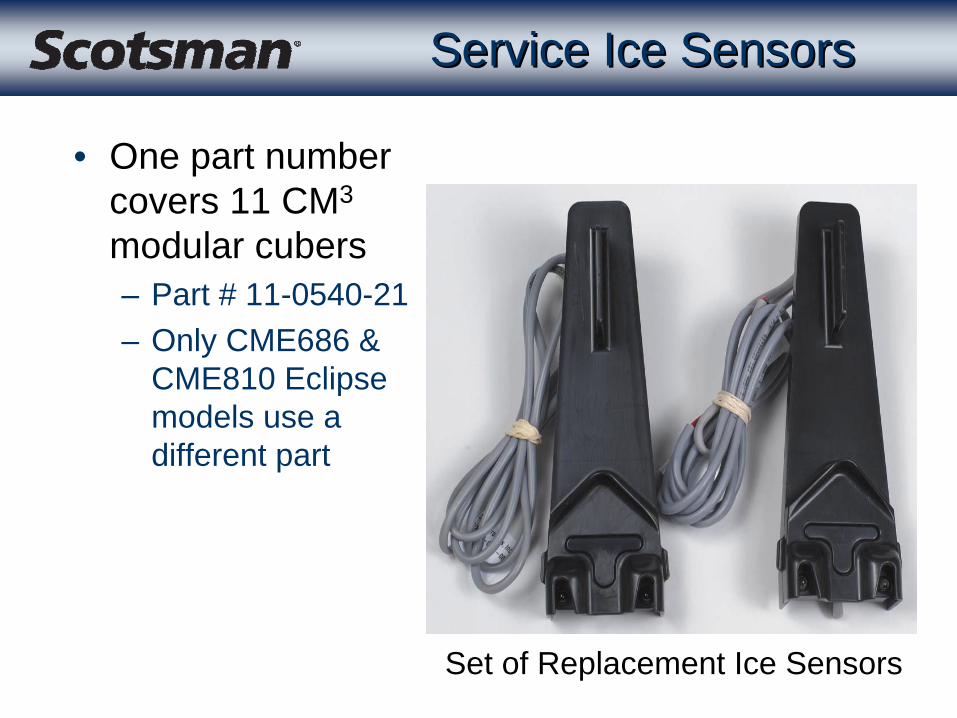
Service Ice SensorsService Ice Sensors
• One part number covers 11 CM3
modular cubers– Part # 11-0540-21– Only CME686 &
CME810 Eclipse models use a different part
Set of Replacement Ice Sensors

Scale on Ice SensorsScale on Ice Sensors
I worked until I got this dirty.
Clean Me!

Removal of SensorsRemoval of Sensors
• Remove cascading shield– Used on all two
evaporator models• Reach in and twist
cascading shield’s top forward to release it from its snap-on mounts
• Push-pull sensors out of the machine

Cleaning SensorsCleaning Sensors
• Clean sensors– Two types - tunnel
mounted and module mounted
– Eyes either in the back of the tunnel or on the module
– Clean both with cotton swab or soft cloth
Tunnel Type Module Mounted

Cleaning SensorsCleaning Sensors
Clean Eyes
Remove Module Reassemble
Check Wire
Compressor DiagnosisCompressor Diagnosis
• Will not start– Check voltage at the compressor– Check resistance of windings
• Is there any?• Off on overload?• Has the compressor overheated?
– Check start relay or PTCR– Check start capacitor
• TXV not opening• Low charge• Hot gas valve leaks thru

Compressor DiagnosisCompressor Diagnosis
• Trips breaker– Check for shorted winding– Could be defective breaker
• Low capacity– Check for other cause
• Water in bin• TXV, hot gas valve, low charge, inlet water valve leak
thru, dirty condenser, high ambients• Hot water back up
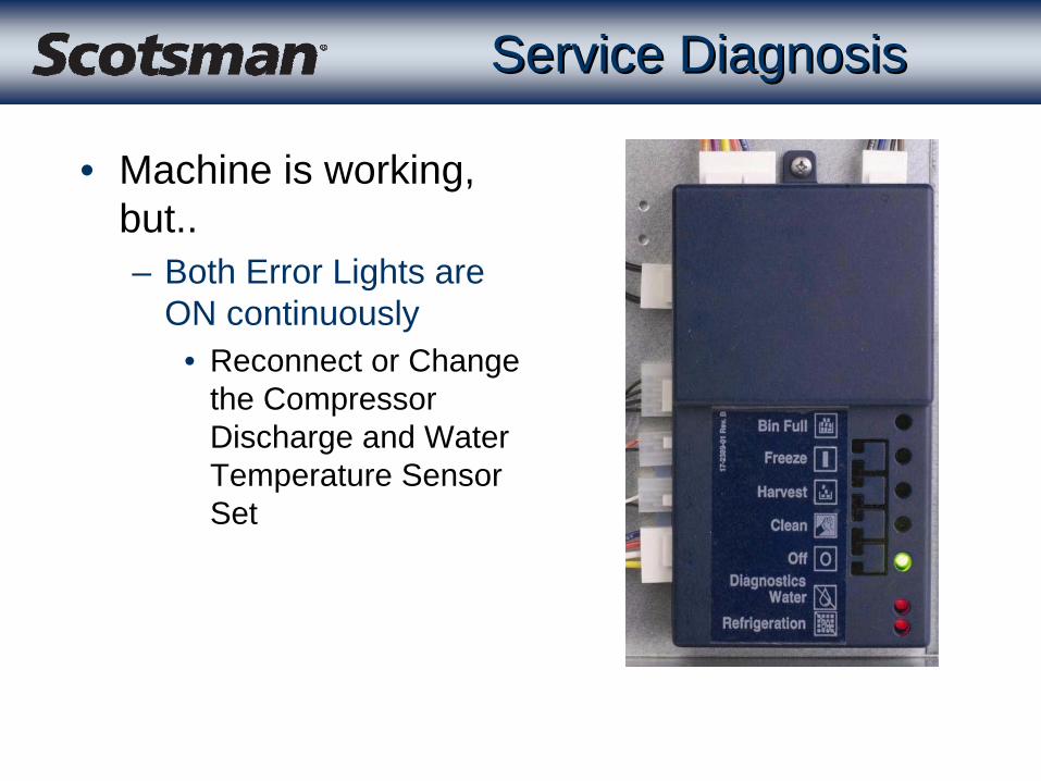
Service DiagnosisService Diagnosis
• Machine is working, but..– Both Error Lights are
ON continuously• Reconnect or Change
the Compressor Discharge and Water Temperature Sensor Set

TXV DiagnosisTXV Diagnosis
• Controls refrigerant flow to maintain suction line temperature– Bulb must be securely clamped in the right position
AND insulated– Most multiple evaporator machines have a
refrigerant distributor & externally equalized TXVs• CME506 “E” and up have two internally equalized
TXVs– Low charge can look like TXV not metering
Charge DiagnosisCharge Diagnosis
• Low charge can cause– High compressor temperatures– Ice not forming at the top of ALL evaporators– Long cycle times
• Controller may shut unit down
• Weigh OUT the charge to confirm
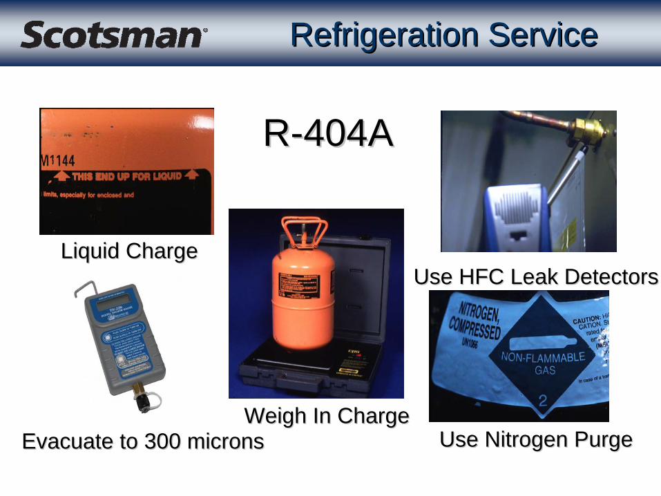
Refrigeration ServiceRefrigeration Service
Liquid ChargeLiquid Charge
Weigh In ChargeWeigh In ChargeEvacuate to 300 micronsEvacuate to 300 microns Use Nitrogen PurgeUse Nitrogen Purge
Use HFC Leak DetectorsUse HFC Leak Detectors
RR--404A404A
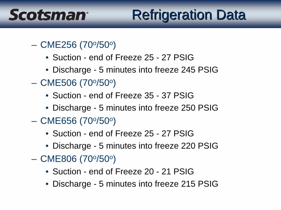
Refrigeration DataRefrigeration Data
– CME256 (70o/50o)• Suction - end of Freeze 25 - 27 PSIG• Discharge - 5 minutes into freeze 245 PSIG
– CME506 (70o/50o)• Suction - end of Freeze 35 - 37 PSIG• Discharge - 5 minutes into freeze 250 PSIG
– CME656 (70o/50o)• Suction - end of Freeze 25 - 27 PSIG• Discharge - 5 minutes into freeze 220 PSIG
– CME806 (70o/50o)• Suction - end of Freeze 20 - 21 PSIG• Discharge - 5 minutes into freeze 215 PSIG
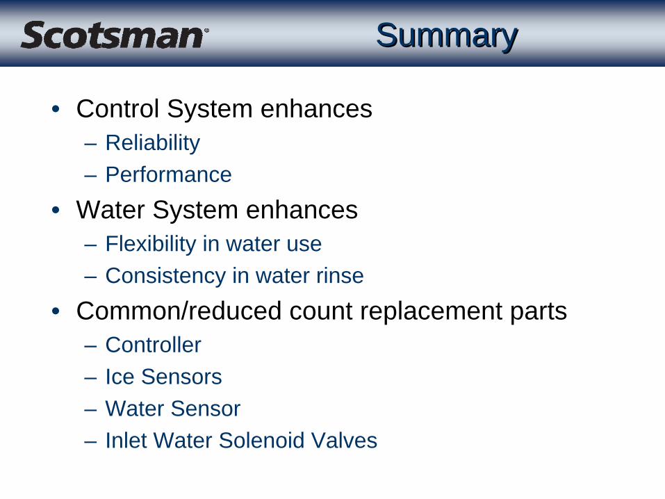
SummarySummary
• Control System enhances– Reliability– Performance
• Water System enhances– Flexibility in water use– Consistency in water rinse
• Common/reduced count replacement parts– Controller– Ice Sensors– Water Sensor– Inlet Water Solenoid Valves