masport vacuum/pressure pump owner/operator … vacuum/pressure pump owner/operator manual models:...
TRANSCRIPT

PRICE: $5.00 90358-1
MASPORT INCORPORATED
Toll Free 1(800) 228-4510www.masportpump.com
© Masport Incorporated All Rights Reserved
Phone (402) 466-8428Fax (402) 466-8355
6801 Cornhusker Hwy.Lincoln, NE 68507
Masport Vacuum/Pressure PumpOwner/Operator Manual
Models: HXL4V, HXL4F, H4V, H4F,

I. LIMITED WARRANTY.......................................................................... II. PLUMBING AND INSTALLATION....................................................... A. INSTALLATION............................................................................... B. PLUMBING CONNECTIONS.........................................................
III. PUMP PROTECTION COMPONENTS............................................ A. PRIMARY SHUT-OFF..................................................................... B. SECONDARY MOISTURE TRAP / SCRUBBER............................ C. VACUUM RELIEF VALVE............................................................... D. PRESSURE / VACUUM GAUGE.................................................... E. SWING CHECK VALVE.................................................................. F. REMOTE 4-WAY VALVE................................................................ G. PRESSURE RELIEF VALVE.......................................................... H. OIL SEPARATOR........................................................................... I. COMPONENT CHECKLIST............................................................
IV. INSTALLATION DIAGRAMS........................................................... A. FLANGE PUMP MODELS.............................................................. B. INTEGRAL VALVE PUMP MODELS..............................................
V. START-UP AND OPERATION INSTRUCTIONS.............................. A. LUBRICANT.................................................................................... B. LUBRICATOR ADJUSTMENTS AND SETTINGS..........................
VI. IMPORTANT OPERATING TIPS........................................................ A. GENERAL OPERATING TIPS........................................................
VII. PUMP MAINTENANCE................................................................. A. DAILY MAINTENANCE................................................................... B. PUMP STORAGE........................................................................... C. PUMP REPAIR KIT INSTALLATION............................................... VIII. PUMP DISASSEMBLY............................................................... A. ENDCOVER REMOVAL................................................................. B. ROTOR REMOVAL........................................................................ C. BEARING REMOVAL..................................................................... D. BEARING REPLACEMENT............................................................ E. OIL SEAL REMOVAL AND REPLACEMENT................................
TABLE OF CONTENTS pg. 1
pg. 2
22
pg. 2-4222333334
pg. 4-545
pg. 5-655
pg. 66
pg. 7-8777
pg. 8-109999
10
I. Table of contents continued next page

IX. PUMP ASSEMBLY............................................................................
X. LIST OF OIL TYPES...............................................................................
XI. PARTS LIST......................................................................................
TABLE OF CONTENTS (continued)
II.
Do Not attempt to install, operate, or service this pump without reading and understanding the corresponding section in this manual.
pg. 10-11
pg. 12
pg. 13-18
PURCHASER - KEEP FOR RECORD TERMS OF LIMITED WARRANTY: 12 MONTHS DATE PURCHASED: SERIAL NUMBER:
1
I. LIMITED WARRANTYManufacturer warrants defects in workmanship, materials or parts for a period of twelvemonths from date of sale. The limited warranty is restricted to repair or replacement of parts or pumps at Masport Incorporated’s discretion. Masport Incorporated neither assumes, nor authorizes any person to assume any other obligation or liability in connection with Masport Incorporated’s products, parts or services sold or delivered. Masport Incorporated shall not be liable for injury or damage to property other than the products or parts themselves, nor for incidental, consequential or special damages.
1. The product must be returned to Masport Incorporated. The limited warranty does not cover the cost of collection or delivery.
2. Any claim under this limited warranty must be made in writing and received within twelve months from date of sale. Claims should be addressed to Masport Incorporated. Masport Vacuum/Pressure Pump Warranty Claims Department, 6140 McCormick Drive, Lincoln, NE 68507-3296.
3. This limited warranty will not apply to any malfunction, defect, or damage of any product resulting from repair or alteration other than by Masport Incorporated.
4. This limited warranty excludes the following: damage during shipment, damage from other than normal or intended use, normal wear, any defects arising from installation or operation of the products other than in accordance with the operating instructions provided, or any product which has been subject to misuse, neglect, or accident.
5. This limited warranty is not transferable and shall extend only to the original purchaser.
Masport HXL4V, HXL4F, H4V, H4FOwner/ Operator Manual

II. PLUMBING AND INSTALLATION
A. INSTALLATION
The vacuum pump should be installed on a level and secure base. If installed in a tool box or other enclosed area, make sure there is enough ventilation to properly cool the pump.
2
B. PLUMBING CONNECTIONS
The plumbing between the pump, the vacuum tank and components should have at least a 1 1/2” I.D. Do not use a hose that is smaller than 1 1/2” I.D. or the airflow will be restricted and the pump may overheat and be damaged.
The type of hose used is very important to the performance of the system. The hose must be rated for full vacuum in all cases. When pressure off-loading, the hose should be rated for 20 PSI minimum. The interconnecting hose is also subjected to high temperatures (300° F) and oil, which may cause damage to the liner of some hoses.
Masport recommends the use of “Hot Tar and Asphalt Hose” for plumbing connections between the pump, components, and tank. It is also recommended that two hose clamps be used to secure each hose connection.
III. PUMP PROTECTION COMPONENTS
A. PRIMARY SHUT-OFF
A primary shut-off is very important to prevent a solid column of liquid from entering the pump and damaging or ruining the pump. It is a liquid level shut-off that does not allow the tank to overflow into your vacuum system.
B. SECONDARY MOISTURE TRAP / SCRUBBER
A secondary moisture trap / scrubber is an important liquid separating device. It removes the small amounts of liquid still in the air after the primary. It is essential to prevent liquid from entering the vacuum pump, which would severly damage the pump. Drain after every tank load.
C. VACUUM RELIEF VALVE
A vacuum relief valve must be installed on any vacuum system. This valve acts to govern the operating vacuum level. It is installed directly at the pump so if a liquid level trap is activated or hose collapses, the pump is not allowed to deadhead.

Failure to install a vacuum relief valve can result in damage to the pump due to running the pump outside of the manufacturer’s recommendations. Valves are available from Masport Inc. or a Masport Authorized Distributor.
3
D. PRESSURE / VACUUM GAUGE
A gauge is required to properly monitor the performance of the system. The gauge should be placed between the pump and the scrubber, which is the clean side, to prevent gauge failure due to foreign materials.
E. SWING CHECK VALVE
If a remote 4-way valve is used, swing check valve should be installed to prevent the pump from spinning backwards when the pump is disengaged with vacuum or pressure in the tank. Failure to install could have a number of effects. When the pump spins backwards, there is risk to damaging the bearings. Also, there is air flowing backwards through the system which would carry foreign material into the vacuum pump and possibly cause severe damage.
CAUTION: The swing check valve must be installed in a horizontal position.
F. REMOTE 4-WAY VALVE
For installation requiring a flange style pump, a remote 4-way valve must be used if vacuum loading and pressure off-loading is desired. With one side of the valve attached to the intake side of the pump and the other attached to the exhaust side of the pump, the mode of operation can be changed from vacuum to pressure by simply turning the selector lever. A swing check valve should be used on all systems with the capability of vacuum and pressure modes.
G. PRESSURE RELIEF VALVE
When using the system for vacuum loading and pressure off-loading, a pressure relief valve is an absolute necessity. Failure to prevent over-pressurizing the pump, tank or system components with a properly sized relief valve could result in system damage or personal injury. ASME code pressure relief valves are available from Masport Inc. or any Masport Authorized Distributor.
H. OIL SEPARATOR
The oil separator reduces the amount of oil in the exhaust air, which makes jobsite clean-up quicker and easier. A brass ball valve is mounted at the bottom for easy draining. Drain the oil separator twice daily.

4
I. COMPONENT CHECKLIST
Below is a checklist of the components needed to complete a Vacuum Only (V) or Vacuum / Pressure (V/P) system.
IV. INSTALLATION DIAGRAMS
V V/P Recommend Masport Component List H4F, H4V,HXL4F, HXL4V
X X Inlet Filter 15115X X Primary Shut-Off Trap 16311X X Secondary Moisture Trap / Scrubber 16410X X Oil Separator 15462-5X X Vacuum Relief Valve 25056 X A.S.M.E. Pressure Relief Valve (10 psi, 15 psi) 25033, 25003X X Pressure / Vacuum Gauge 21051X X Swing Check Valve* 25128
X Remote 4-way Valve* 968106*For Flange Pump Model Installation Only
A. FLANGE PUMP MODELS
Vacuum OnlySystem
Drawing 90414

Drawing 90417
5
B. INTEGRAL VALVE PUMP MODEL
Vacuum / PressureSystem
Masport
NEW ZEALAND
A. LUBRICANT
A high quality Rotary Compressor or Rotary Turbine Oil should be used. Oil is available through any Masport Authorized Distributor or from Masport Inc.
B. LUBRICATOR ADJUSTMENTS AND SETTINGS
Automatic Mechanical Oil Pump Type for Pump Models: HXL4F, HXL4V
This system utilizes a direct gear driven oil pump which is preset to deliver the required amount of lubricating oil to the vacuum pump. The oil pump is maintenance free and requires no operator adjustment.
IMPORTANT: The oil reservoir must be mounted higher than the oil feed connection on the pump. The oil pump must be primed before initial start-up. The oil pump must be bleed prior to initial operation and any time afterwards when the oil pump is operated without oil for any period of time.
Adjustable Vacuum / Pressure Actuated Type for Pump Models: H4F, H4V
This system utilizes three adjustable oil sight feed valves attached to a remote mounted oil reservoir. See Diagram 13459 on page 18.
V. START-UP AND OPERATION INSTRUCTIONS

6
On Pump models H4F and H4V, the lubricant flow rate is regulated in part by the vacuum or pressure level the pump is operating at, and in part by the setting of the needles on the sight feed valves. This type of lubrication system will not dispense any oil until the vacuum pump is operating under a vacuum or pressure condition.
Once the pump is installed and a vacuum can be drawn, start the pump and adjust the R.P.M. to give the correct pump speed. Check the pump speed at the shaft and make a note of the engine’s tachometer speed for future reference. With the valves on the truck closed, continue to draw a vacuum until the vacuum gauge reaches 15” Hg. At this point, the sight feeds should be adjusted to deliver 30 to 60 drops per minute at each of the site feeds.
Once the flow rate is set, the needle packing nuts can be tightened to help maintain the setting. Care should be taken to not over-tighten the packing nuts as damage to the packing will result.
When the system is used for pressure, the flow rates should be adjusted when the tank pressure is at approximately 10 PSIG. Exact flow rates are not critical as long as the system is operating in the 30 to 60 DPM range at its normal operating vacuum or pressure.
A. GENERAL OPERATING TIPS
Do’s • Regularly check to ensure pump R.P.M. is at recommended speed. • Flush pump daily. • Check and clean components regularly. • Drain Oil Separator twice daily. • Drain Scrubber after each load. • Check and clean Prefilter regularly. • Always bleed tank to atmosphere before switching valve from vacuum to pressure or pressure to vacuum. • Ensure Vacuum Relief Valve and Pressure Relief Valve are installed in system and adjusted to recommended settings.
Don’ts • Do not open ball valve on Scrubber with vacuum on tank. This will allow foreign material to enter the pump. • Do not over speed or under speed the pump. • Do not engage PTO at high R.P.M. Only engage at idle. • Never run pump without oil. • Never spin pump backwards. • When draining Scrubber, if nothing comes out when ball valve is opened, never assume the Scrubber is empty. Check for blockage.
VI. IMPORTANT OPERATING TIPS

7
A. DAILY MAINTENANCE
To eliminate build-up of foreign material on the inner workings of the pump and ensure smoother operation and maximum pump life, it is recommended that the pump be flushed every day or immediately after any liquid or solids have been drawn into the pump. To flush the pump, follow the directions in the flush kit or the directions below:
FLUSHING PROCEDURE
VII. PUMP MAINTENANCE
B. PUMP STORAGE
If the pump is likely to remain idle for two weeks or more, it is advisable to pour one ounce of oil into the center lubrication or suction inlet and one ounce into each bearing lubrication inlet. Then rotate the pump slowly, preferably by hand, to thoroughly lubricate the pump’s inner surfaces.
C. PUMP REPAIR KIT INSTALLATION
The following repair techniques are given for pumps that do not have damage to the cylinder or endcovers to the extent that they need to be re-machined. These procedures are intended for use when the vanes and bearings of the pump require replacement. They should not be considered as total rebuild instructions.
123456789
10*
Part DescriptionCap Lubricator TankLubricator Tank 4 QuartsHose 1/4”Hose ClampPushlock 1/4” BrassElbow 1/4” BrassFlow RestrictorBracket Flushing KitNipple 1/4”Ball ValveLabel
3600236001242992431027001270022703233461300002515439013
11213211111
Flushing Kit for Masport Vacuum Pumps (part # 13027)
1. Start vacuum pump and bring to 15” Hg. 2. Open ball valve to begin flushing fluid flow. 3. Continue to run pump until field level drops 1 graduation (7 fluid OZ). 4. Close ball valve. 5. Continue to operate pump 1 additional minute to ensure all fluid is purged from the pump. 6. Stop vacuum pump. 7. Drain Oil Separator and dispose used fluid at approved recycling site.
8
Installations requiring re-matching of the pump components should be done by an Authorized Masport Repair Facility. For the nearest Authorized Rebuild Center contact Masport Inc. at 1-800-228-4510.
The pump should be inspected at least once a year to check the progress of vane wear. If the vanes are not monitored, they can become too short, be forced out of their slots during operation and cause major structural damage to the pump.
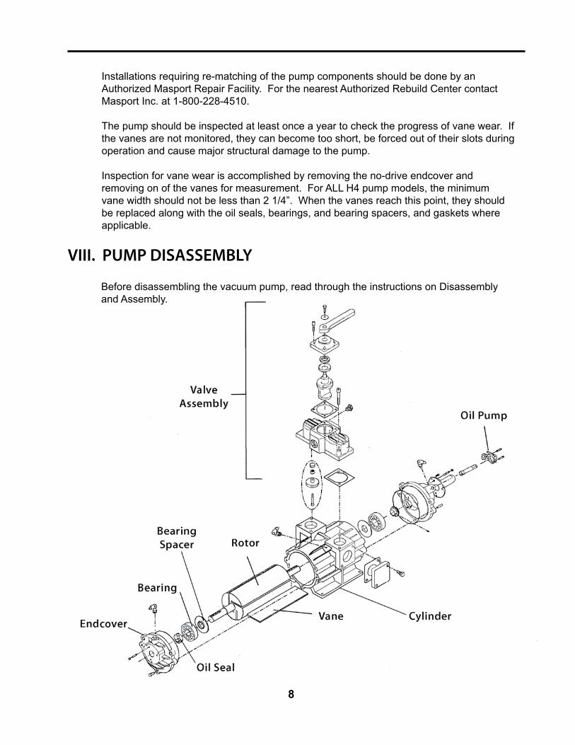
Inspection for vane wear is accomplished by removing the no-drive endcover and removing on of the vanes for measurement. For ALL H4 pump models, the minimum vane width should not be less than 2 1/4”. When the vanes reach this point, they should be replaced along with the oil seals, bearings, and bearing spacers, and gaskets where applicable.
VIII. PUMP DISASSEMBLY
Before disassembling the vacuum pump, read through the instructions on Disassembly and Assembly.

9
A. ENDCOVER REMOVAL
With the pump removed from the system, mark the drive side endcover and the corresponding end of the cylinder, using a center punch. Marking these will avoid the possibility of assembling the pump with the endcovers on the wrong ends. Once the endcover and the cylinder are marked, remove the endcover bolts. Drive the endcover off the dowel pins with a flat ended punch. Place the punch on the cover removal boss cast into the cover along side the dowel pin holes.
Caution: In order to maintain factory set clearances, avoid damaging the dowel pins during endcover removal. To properly remove the endcover, work evenly from each side of the cover, which will help to avoid misalignment of the endcover and bending of the dowel pins. Never pry on the endcover. When removing the endcover, do not allow the rotor to drop, as contact with the cylinder may cause cylinder or rotor damage.
B. ROTOR REMOVAL
With the one end cover removed, the rotor can be pulled out of the cylinder. Thebearings are a slip fit in the endcovers, but due to the tight clearance, the bearing may bind in the endcover if it is not pulled out straight. If it does not pull free on the first try, put it all the way back in, using a rubber mallet, and start over again. Putting it all the way back in will realign the bearing with the housing and allow it to pull free form the cover.
C. BEARING REMOVAL
Bearings should be removed only using the proper tools. A bearing puller is the only tool that will give satisfactory results. Prying or hammering will only risk damage to the components. The bearing spacers behind the bearings are not reusable; even the best bearing puller will damage them and make them unfit for use.
D. BEARING DISPLACEMENT
Place the new spacer on the shaft, taking care to place the side with the largest inside diameter toward the rotor (see figure 1). Next, the new bearing can be pressed onto the shaft. If there is a bearing press available, use it. If not, freeze the rotor to shrink it, use a 1” pipe with a pipe cap on it to drive the new bearing onto the shaft. Drive the bearing onto the rotor shaft using the inner race only. Striking the bearing on the outer race will damage the bearing and cause failure.

E. OIL SEAL REMOVAL AND REPLACMENT
10
Rotor Between Bearing Spacers
To remove the oil seal, place the endcover on a flat surface with the inside facing down. Use a flat faced punch to drive the seal out, working it a bit at a time from side to side until it comes free. To install the new seal, turn the cover over and place the new seal in the housing with the spring loaded side of the seal facing up (see figure 2). The seal can now be driven into place using the flat side of a large socket. Use care to get the seal started straight into the endcover using light taps. Then drive the seal onto its seat, working evenly around the diameter to prevent damaging the seal.
IX. PUMP ASSEMBLY
Before going any further, make certain the pump parts and work area are clean. Attempting to reassemble the pump with oil or dirt on the parts will make any clearance adjustments impossible.
1. Clean the rotor surface and the non-drive endcover surfaces.
2. Replace any endcover gaskets that were on the pump with the same quantity and color. Place the non-drive endcover on the cylinder and tap the endcover onto the dowel pins evenly with a rubber mallet (be sure the center punch marks made during disassembly are lined up). Replace the endcover retaining bolts and torque to 15 ft. lbs.
3. Insert the rotor into the cylinder. Be sure to line the bearing bore and the bearing up, so the rotor slides into the cylinder easily. The rotor may need to be tapped into the cylinder with a rubber mallet.

11
4. Insert vanes into the slots, taking care that the edge of the vanes that is beveled is inserted towards the inside of the rotor. (See Figure 3)
5. Place the drive side endcover onto the shaft, taking care not to damage the oil seal. Once again, drive the endcover onto the dowel pins with a rubber mallet. Replace the endcover retaining bolts and torque to 15 ft. lbs.
6. Turn the pump by hand, making certain the pump turns freely and is not binding. If it will not go all the way around, take one of the endcovers off and make sure the vanes are free and squarely in their slots. Reassemble and check it again.
7. When everything turns freely, the pump can be installed back on the system.
CAUTION: Make certain to lubricate the pump before initial start-up to prevent damage in the first few seconds of operation.
If the pump clatters at operational speeds, stop the unit immediately and correct the condition.
For additional information or any assistance, contact your Authorized Masport Representative or contact:
MASPORT INCORPORATED6801 Cornhusker Hwy.
Lincoln, NE 68507402-466-8428
Fax: 402-466-8355TOLL FREE: 1-800-228-4510
www.masportpump.com
Figure 3

12
X. LIST OF OIL TYPES
90104 © 2008 Masport Incorporated All Rights Reserved
MASPORT VACUUM PUMP OIL IS THE ONLYRECOMMENDED OIL FOR MASPORT PUMPS.
SUBSTITUTE OILS RECOMMENDED FOR TEMPORARY USE IN MASPORT VACUUM / PRESSURE PUMPS
MASPORT VACUUM PUMP OILMasport Incorporated - Lincoln, NE 800-228-4510
OILS OR FLUIDS THAT SHOULD NOT BE USED IN MASPORT VACUUM PUMPS
SHELL TURBO T OIL 32, 68, 100Shell Oil Company - Houston, TX...................................................800-231-6950
MONOLEC COMPRESSOR OIL*Lubrication Engineers - Fort Worth, TX...........................................817-834-6321
MOBIL SHC 525 (Synthesized Hydrocarbon)Mobil Oil Company - Fairfax, VA....................................................800-662-4525
ANDEROL 497Anderol Inc - East Hanover, NJ.......................................................888-263-3765
CHEVRON GST 32, 68ChevronTexaco Corporation - San Ramon, CA...............................800-822-5823
PENNZBELL TO OIL 32, 46, 68Pennzoil Oil Company - Houston, TX ............................................800-332-6457
REGAL OIL R & O 32, 68ChevronTexaco Corporation - San Ramon, CA...............................800-822-5823
* Monolec Compressor Oil is colored red and should not be confused with transmission fluid.
These oils have been approved for use in Masport Vacuum/Pressure Pumps. Use of these oils will extend the life of the vacuum pump and insure proper performance and lubrication.
NOTE: Oils numbered 32 & 46 are for winter use**. Oils numbered 68 & 100 are for summer use.**Check pour point to determine minimum temperature.
One Gallon Case of 6 GallonsSummer Blend (20 Wt.) 13996 13997Winter Blend (10 Wt.) 13998 13999
TRANSMISSION FLUID AUTOMOTIVE MOTOR OIL POWER STEERING FLUID
USED OIL VEGETABLE OIL BRAKE FLUID
HYDRAULIC FLUID GEAR OIL SCENTED OIL

HXL4V AIR COOLED PRESSURE / VACUUM PUMP PARTS LIST (968440)
90055 © MASPORT INCORPORATED All Rights Reserved Effective 4-1-2007
PARTSLISTHXL4V
* * NOT SHOWN * * * QUANTITY VARIES
Ref Description Part No. Qty. Ref Description Part No. Qty. 1 Bolt 501569 10 21 Spool 968052 1 2 Nut 501682 6 23 Plug 143901 1 3 Set Screw 504274 3 24 Valve Body 968081 1 4 Endcover 975479 1 25 Gasket 568066 2 5 O-Ring 501004 2 26 Gear 568069 1 6 Swivel Elbow * 568086 3 27 Endcover 975468 1 7 Oil Seal 501676 2 28 Swivel Elbow * 568085 1 8 Bearing 500082 2 29 Bolt 501571 3 9 Bearing Spacer 975496 2 30 Set Screw 504275 3 10 Rotor Assembly 975469 1 31 Shaft Guard 961412 1 (Includes 8, 9) 32 Drive Shaft Assembly 975482 1 11 Cylinder 975471 1 33 Oil Pump 575437 1 12 NRV Poppet Assembly 968068 1 34 Cap Screw 504262 1 13 Gasket 568063 1 35 Cap Screw 504261 1 14 Washer 568056 2 36 Dowel Pin 575111 4 15 Cap 968053 1 37 Set Screw 504264 1 16 Cap Screw 568064 4 38 Blank Flange 975487 2 17 Washer 503196 1 39 Gasket 568009 2 18 Bolt 501702 1 40 Vane Pack (4) 975393 1 19 Handle 968055 1 41 Integral Valve Assembly 968070 1 20 Oil Seal 501578 1 (Incl. 12, 13, 14, 15, 16, 22 Cap Screw (Serial # < 98420) 568065 4 17,18,19,20,21,23,24) (Serial # > 98419) 568241 4 42 Oil Line (ft.) * * 600293 * * *
13

90056 © MASPORT INCORPORATED All Rights Reserved Effective 4-1-2007
PARTSLISTHXL4F
HXL4F AIR COOLED PRESSURE / VACUUM PUMP PARTS LIST (968435)
* NOT SHOWN. * * QUANTITY VARIES.
Ref Description Part No. Qty. Ref Description Part No. Qty. 1 Bolt 501569 10 15 Endcover 975468 1 2 Nut 501682 6 16 Swivel Elbow 568085 1 3 Set Screw 504274 3 17 Bolt 501571 3 4 Endcover 975479 1 18 Set Screw 504275 3 5 O-Ring 501004 2 19 Shaft Guard 961412 1 6 Swivel Elbow 568086 3 20 Drive Shaft Assembly 975482 1 7 Oil Seal 501676 2 21 Oil Pump 575437 1 8 Bearing 500082 2 22 Cap Screw 504262 1 9 Bearing Spacer 975496 2 23 Cap Screw 504261 1 10 Rotor Assembly 975469 1 24 Dowel Pin 575111 4 (Includes 8, 9) 25 Set Screw 504264 1 11 Cylinder 975471 1 26 Bolt 501878 4 12 Gasket 568009 4 27 Flange 968159 2 13 Blank Flange 975487 2 28 Vane Pack (4) 975393 1 14 Gear 568069 1 29 Oil Line (ft.) * 600293 * *
14

90053 © MASPORT INCORPORATED All Rights Reserved Effective 4-1-2007
PARTSLISTH4V
H4V AIR COOLED PRESSURE / VACUUM PUMP PARTS LIST (968430)Ref Description Part No. Qty. Ref Description Part No. Qty. 1 Bolt 501569 10 18 Bolt 501702 1 2 Nut 501682 6 19 Handle 968055 1 3 Set Screw 504274 6 20 Oil Seal 501578 1 4 Endcover 975479 2 21 Spool 968052 1 5 O-Ring 501004 2 22 Cap Screw 6 Oil Seal 501676 2 (Serial # < 98420) 568065 4 7 Bearing 500082 2 (Serial # > 98419) 568241 4 8 Bearing Spacer 975496 2 23 Plug 143901 1 9 Rotor Assembly 975464 1 24 Valve Body 968081 1 (Includes 7, 8) 25 Gasket 568066 2 10 Plug 503416 2 26 Bolt 501571 3 11 Cylinder 975471 1 27 Shaft Guard 961412 1 12 NRV Poppet Assembly 968068 1 28 Dowel Pin 575111 4 13 Gasket 568063 1 29 Blank Flange 975487 2 14 Washer 568056 2 30 Gasket 568009 2 15 Cap 968053 1 31 Vane Pack (4) 975393 1 16 Cap Screw 568064 4 32 Integral Valve Assembly 968070 1 17 Washer 503196 1 (Incl. 12,13,14,15,16,17, 18, 19, 20, 21, 23, 24)
15

90054 © MASPORT INCORPORATED All Rights Reserved Effective 4-1-2007
PARTSLISTH4F
H4F AIR COOLED PRESSURE / VACUUM PUMP PARTS LIST (968425)Ref Description Part No. Qty. Ref Description Part No. Qty. 1 Bolt 501569 10 10 Plug 503416 2 2 Nut 501682 6 11 Cylinder 975471 1 3 Set Screw 504274 6 12 Gasket 568009 4 4 Endcover 975479 2 13 Blank Flange 975487 2 5 O-Ring 501004 2 14 Bolt 501571 3 6 Oil Seal 501676 2 15 Shaft Guard 961412 1 7 Bearing 500082 2 16 Dowel Pin 575111 4 8 Bearing Spacer 975496 2 17 Bolt 501878 4 9 Rotor Assembly 975464 1 18 Flange 968159 2 (Includes 7, 8) 19 Vane Pack (4) 975393 1
16

90697 © MASPORT INCORPORATED All Rights Reserved
13459 Remote 3 Feed LubricatorPump Pressure Actuated
Reference: Description Part Number Qty1 Oil Reservoir 18059 12 O-Ring (for cap) 36112 13 Lubricator Cap 27200 14 1/8” Brass Pushlock 27003 55 1/8” Brass Street Elbow 27004 26 3 Point Sight Feed 25320 17 1/4” Brass Street Elbow 27002 28 Level Indicator Elbow 27008 29 1/4” OD Poly Tubing (in.) 24300 6”
10 1/4” Brass Pushlock 27001 311 1/4” Pushlock Hose (ft.)* 24299 15’
* Not Shown
Parts List 13459Remote 3 Feed Lubricator
1790087 © MASPORT INCORPORATED All Rights Reserved
OIL RESERVOIR KIT (13023)
Reference: Description Part Number Qty1 8 ft. Hose 1/4” 24299 12 Lubricator Tank 4 Qt. 36001 13 Clamps MXL #4 24310 2
PARTS LISTOIL RESERVOIR KIT

90697 © MASPORT INCORPORATED All Rights Reserved
13459 Remote 3 Feed LubricatorPump Pressure Actuated
Reference: Description Part Number Qty1 Oil Reservoir 18059 12 O-Ring (for cap) 36112 13 Lubricator Cap 27200 14 1/8” Brass Pushlock 27003 55 1/8” Brass Street Elbow 27004 26 3 Point Sight Feed 25320 17 1/4” Brass Street Elbow 27002 28 Level Indicator Elbow 27008 29 1/4” OD Poly Tubing (in.) 24300 6”
10 1/4” Brass Pushlock 27001 311 1/4” Pushlock Hose (ft.)* 24299 15’
* Not Shown
Parts List 13459Remote 3 Feed Lubricator
90087 © MASPORT INCORPORATED All Rights Reserved
OIL RESERVOIR KIT (13023)
Reference: Description Part Number Qty1 8 ft. Hose 1/4” 24299 12 Lubricator Tank 4 Qt. 36001 13 Clamps MXL #4 24310 2
PARTS LISTOIL RESERVOIR KIT
18