lewis poultry house blower owner / operator manual … 1 owner book.pdf · lewis poultry house...
TRANSCRIPT

1
LEWIS POULTRY HOUSE BLOWER OWNER / OPERATOR MANUAL
MODEL # PB-1
Manufactured by: Lewis Brothers Manufacturing, Inc. Post Office Box 146 Baxley, GA 31515 Telephone: (912) 367-4651 Fax: (912) 367-3958
7-16-14

2
INTRODUCTION All Lewis Brothers equipment is manufactured under stringent production and quality assurance procedures prior to preparation for shipment. A final quality check is performed on all equipment before shipping. The best equipment is only as good as its operation and management. Sound operation and good preventive maintenance practices are essential to efficient performance of your Lewis Poultry House Blower. Questions on parts and service for the equipment covered in this manual should be referred to the local dealer from whom the equipment was purchased, or the nearest Lewis Brothers Dealer. We sincerely thank you for purchasing Lewis Brothers equipment.

3
TABLE OF CONTENTS INTRODUCTION 2 SAFETY Owner’s And Operator’s Responsibility 4 General Precautions 5 General Safety Information 5 WARRANTY Limited Warranty 6 SPECIFICATIONS Model PB-1 Specifications 7 OPERATING INSTRUCTIONS 8-19 DECALS 20-21 PARTS 22-27

4
SAFETY OWNER'S AND OPERATOR'S RESPONSIBILITY This manual is intended for use with your Lewis Poultry House Blower. Extra effort has been taken to provide for the safe operation of this equipment. This manual, as well as the safety decals placed on the equipment, is part of that effort. Your new Poultry House Blower should perform the functions for which it was designed if it is maintained and adjusted as described in this manual. It is the responsibility of the owner and each operator of this equipment to read and understand this manual prior to using the machine and before performing any service or maintenance tasks on the equipment. Each person who will work on or around this equipment should be properly instructed in how to do so safely. It is important to understand the operational methods and safety issues mentioned in this manual. Lewis Brothers cannot anticipate all conceivable ways service and operational functions might be performed and of the possible hazardous consequences of such. Anyone using or servicing this equipment must first satisfy themselves that their chosen methods do not jeopardize the safety of themselves, others, or the equipment. Read the warranty on page 6. The purchaser is required to fill out and return the registration card supplied with this owner's manual within ten (10) days of purchase to Lewis Brothers Manufacturing to be eligible for warranty coverage. Genuine Lewis replacement parts will insure the durability and long life of your Poultry House Blower. Lewis repair parts and optional equipment should be ordered through your Lewis Brothers' Dealer. Operators should thoroughly inspect the Poultry House Blower before and after each use. Failure to repair or replace worn parts could result in damage or excess wear to other parts. Check belt tension before each use and adjust if necessary.

5
GENERAL PRECAUTIONS • MAKE SURE everyone is clear of the equipment before starting the tractor's engine
and while equipment is under operation. • DO NOT allow anyone to ride on this equipment. • KEEP hands, feet, hair and clothing away from all moving parts. Do not wear loose
clothing while operating equipment, as this may present an entanglement hazard. • DRIVE AND OPERATE the attached tractor at speeds compatible with conditions
and good safety practices. This is especially important when operating over rough ground, on slopes, crossing ditches or while turning.
• MAKE SURE hitch components are attached securely before operating. • USE flashing warning lights when on highways, except where prohibited by law. • KEEP all shields in place. Do not operate the machine if any shields are damaged or
missing. • OBSERVE all safety decals located on machine. Should any safety decal become
damaged, unreadable, or lost, REPLACE IT IMMEDIATELY. New decals may be obtained from your Lewis Brothers' dealer.
GENERAL SAFETY INFORMATION
• Do not operate PTO above recommended RPM. (540 RPM)
• Make certain that the power source conforms to the requirements of your equipment.
• Provide adequate protection in guarding around the moving parts such as the
shaft and pulleys.
• Disconnect power before servicing.
• Release all pressure within the system before servicing any component.

6
WARRANTY LEWIS BROTHERS MANUFACTURING, INC.
LIMITED WARRANTY
Lewis Brothers Manufacturing, Inc. (hereinafter referred to as “LBM”) warrants each item of new equipment manufactured by LBM to be free from defects in material and workmanship under normal use and service. The obligation of LBM under this LIMITED WARRANTY is limited to repair or replacement, as LBM may elect, of any parts that prove, in LBM’s judgment, to be defective in material and workmanship within the first twelve (12) months after the date of invoice to the original purchaser. THIS LIMITED WARRANTY DOES NOT APPLY TO BELTS, HYDRAULIC HOSES, AND OTHER SERVICE ITEMS, WHICH SHALL HAVE A NINETY (90) DAY WARRANTY. THIS LIMITED WARRANTY WILL APPLY FOR (3) MONTHS ONLY WHEN THE UNIT IS USED IN A COMMERCIAL APPLICATION. All warranty part repairs and replacements must be made by a certified LBM dealer. Any outside work or alterations made without written approval of LBM will render this LIMITED WARRANTY void. LBM’s obligation specifically excludes any liability for consequential damages, such as loss of profit, delays, expenses, damage to goods or property used in connection with or processed in or by the product sold, or damage to the product sold from whatever cause, whether or not such loss is due to negligence by LBM. This LIMITED WARRANTY shall not apply to any item that has been operated in a manner not recommended by LBM. No person is authorized to give any other warranties or to assume any other liability on behalf of LBM unless made in writing by Lewis Brothers Manufacturing, Inc. THIS LIMITED WARRANTY IS IN LIEU OF AND REPLACES ALL OTHER WARRANTIES, EXPRESSED OR IMPLIED. WARRANTIES OF MERCHANTABILITY AND FITNESS FOR A PARTICULAR PURPOSE ARE EXCLUDED, AS ARE ALL OTHER REPRESENTATIONS TO THE USER-PURCHASER AND ALL OTHER OBLIGATIONS OR LIABILITIES, INCLUDING LIABILITY FOR INCIDENTAL AND CONSEQUENTIAL DAMAGES, ON THE PART OF LBM.
LEWIS BROTHERS MANUFACTURING, INC. P.O. BOX 146 - BAXLEY, GA. 31513
JULY 1, 2012

7
SPECIFICATIONS POULTRY HOUSE BLOWER MODEL PB-1 Height 57” Width 39” Length 55.5” Weight (WITHOUT OPTIONAL SPRAYER KIT) 480 lbs. Fan Size 12” x 12” CFM 6000 Volute 15.5” PTO Horsepower (Minimum) 20HP OPTIONAL SPRAY KIT Pump Max PSI @ 540 R.P.M. 300 Pump Max Flow @540 9.7 GPM Tank Volume 55 Gallons Spray tips 4 Required Spray on off Valve 12 Volt Solenoid Weight (WITH OPTIONAL SPRAYER KIT) 540 lbs.

8
OPERATION AND MAINTENANCE
MACHINE SETUP
TRACTOR SETTINGS The Lewis Poultry House Blower is designed to be operated at 540 rpm PTO. If your tractor is equipped with a 1000 RPM PTO, you should install the 540 shaft adapter.
FIGURE 1

9
ATTACHING POULTRY HOUSE BLOWER TO TRACTOR Attach the Poultry House Blower to the tractor's lift-arms and adjustable link. Next, attach the drive shaft to the tractor PTO shaft. Slide the drive shaft onto the PTO shaft until the lock snaps in place. Always try to pull the drive shaft from the PTO after it is in place. If the drive shaft slides and is not locked in place, repeat the process again to insure proper attachment. Connect the Poultry House Blower’s two hydraulic lines to the selected remote hydraulic ports located on the tractor (See figure 1). IMPORTANT: The Lewis Poultry Blower is designed to handle a maximum system pressure of 2500 PSI. Excess pressure should be avoided in order to prevent damaging system components. Tractors that are capable of supplying higher hydraulic pressure should install a pressure regulator kit (part # PB-800080) to prevent damage to the hydraulic system.
OPERATING INSTRUCTIONS The ground speed will always vary depending on the particular operation being performed. The Lewis Poultry House Blower is designed to be operated with the tractor PTO turning within a range of 500 to 540 RPM. 540 RPM is the most desirable PTO speed producing the maximum pressure from the blower. Place the machine into operation by first engaging the PTO of the tractor with the tractor engine at safe idle speed. Next, rotate the volute right or left to the desired position of operation by moving the tractor remote hydraulic control handle. IMPORTANT: ALWAYS ENGAGE PTO CLUTCH SLOWLY AND SMOOTHLY AT LOW RPM TO AVOID SUDDEN STARTS AND FAST CLUTCHING THAT CAN DAMAGE THE DRIVE COMPONENTS.
FIGURE 2
Drive Belt
Drive Belt Tension Bolt
10
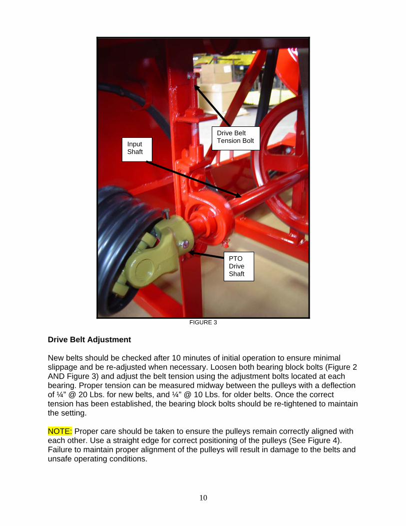
FIGURE 3
Drive Belt Adjustment New belts should be checked after 10 minutes of initial operation to ensure minimal slippage and be re-adjusted when necessary. Loosen both bearing block bolts (Figure 2 AND Figure 3) and adjust the belt tension using the adjustment bolts located at each bearing. Proper tension can be measured midway between the pulleys with a deflection of ¼” @ 20 Lbs. for new belts, and ¼” @ 10 Lbs. for older belts. Once the correct tension has been established, the bearing block bolts should be re-tightened to maintain the setting. NOTE: Proper care should be taken to ensure the pulleys remain correctly aligned with each other. Use a straight edge for correct positioning of the pulleys (See Figure 4). Failure to maintain proper alignment of the pulleys will result in damage to the belts and unsafe operating conditions.
Drive Belt Tension Bolt
PTO Drive Shaft
Input Shaft

11
FIGURE 4
Drive Belt Replacement
1. Remove bolt from PTO drive shaft and disconnect PTO shaft from Blower input shaft (See Figure 3).
2. Loosen the tension on the adjustment bolts for each bearing. By removing the
mounting bolts on each bearing you can remove and replace the drive belt (See Figure 2&3). Repeat the process in reverse order to install the new belt. Once the belt has been installed, refer to the instructions located on page 10 on how to properly adjust belt tension.

12
Volute Rotation Chain Adjustment Adjust the chain tension by turning nut, taking care not to over tighten the chain. If necessary, additional adjustment may be achieved by removing chain links. Take care to remove only excess looseness in the chain (See Figure 5).
FIGURE 5
Adjustment Bolt

13
Sprayer Option
Do not pump flammable or explosive fluids such as gasoline, fuel, oil, kerosene, etc. Do not use in explosive atmospheres. The pump should be used only with liquids compatible with the pump component materials. Do not pump asphalt, asphalt sealer, roofing compounds or concrete sealers or any two step curing products. Personal injury may result and the warranty will be void. If there are any questions, call HYPRO APPLICATIONS toll free number (1-800-445-8360.)

14
• Do not operate PTO above recommended RPM. (540 RPM)
• Operate pump between temperature range of 45°F to 140°F.
• Drain all liquids from the system before servicing.
• Check all hoses for weak or worn condition before each use. Make certain that all connections are tight and secure.
• Periodically inspect the pump and the system components. Perform routine
maintenance as required. (See Maintenance Section)
• Replacement parts should be properly rated for system pressure. Never install used pipe or hoses.
• Do not use these pumps for pumping water or other liquids for human or animal
consumption.
Pump must not be run dry.
FIGURE 6
MOUNT PIN

15
FIGURE 7
Sprayer Set-Up Position pump on mount pin while not in use and secure with pin provided. When spraying, return pump to Input Shaft (See Figure 6 and 7). Controlling the Flow The suction line ball valve should remain open at all times except for maintenance or repair (See Figure 8). Flow and operating pressure can be managed with the manual flow control valve (See Figure 9). Refer to the chart on Page 18 to establish the proper setting for the system pressure and nozzle selection.
FIGURE 8
Suction Ball Valve
INPUT SHAFT

16
FIGURE 9
Spraying Adjustment To adjust sprayer Follow these steps:
1. Prime pump with all valves open.
2. With pump running and nozzle control valve set to open, turn the relief valve handle until pressure gauge indicates desired spraying pressure.
3. Make sure flow is uniform from all nozzles.
4. NOTE: Machine is equipped with Nozzle # 90A1FP3.0 Lime Green. See chart on page 17 and 18 for other options. (Multiply GPM x 4 to get total machine output)
Measuring Travel Speed Measure a test course in the area to be sprayed or in an area with similar surface conditions. Minimum lengths of 100 and 200 feet are recommended for measuring speeds up to 5 and 10 MPH, respectively. Determine the time required to travel the test course. To help ensure accuracy, conduct the speed check with a partially loaded (about half full) sprayer and select the engine throttle setting and gear that will be used when spraying. Repeat the above process and average the time that were measured. Use the following equation or the SPEED TRAVEL TABULATION CHART on page 17 to determine ground speed. SPEED (MPH) = DISTANCE (FT) X 60/TIME (SECONDS) X 88 Check for proper belt tension before each use
FLOW CONTROL
VALVE
Pressure gauge

17
Flush Pump After Use One of the most common causes for faulty pump performance is “gumming” or corrosion inside the pump. Flush the pump and entire system with a solution that will chemically neutralize the liquid pumped. Mix according to manufacturer’s directions. This will dissolve most residues remaining in the pump, leaving the inside of the pump clean for the next use. To prevent Corrosion After cleaning the pump as directed above, Flush it with a permanent-type automobile antifreeze (Prestone, Zerex, etc.) containing a rust inhibitor. Use a solution – half antifreeze and half water. Plug the ports to keep out air during storage. For short periods of idleness, non-corrosive liquids may be left in the pump, BUT AIR MUST BE KEPT OUT. Plug ports or seal port connections.
FAILURE TO FOLLOW INSTRUCTIONS WILL VOID WARRANTY
AFTER EACH USE, THOROUGHLY FLUSH PUMP, CONTROL VALVE, STRAINERS AND SPRAY TIPS WITH WATER OR PROPER SOLVENT. FAILURE TO DO SO COULD CAUSE THE SYSTEM TO MALFUNCTION, AND RESULT IN POSSIBLE INJURY TO THE USER, AND /OR VOID THE WARRANTY.
Speed Travel Tabulation Chart TIME REQUIRED IN SECONDS TO TRAVEL A DISTANCE OD:
SPEED IN MPH
100 Feet 200Feet 300 Feet 1.0 68 136 205 1.5 45 91 136 2.0 34 68 102 2.5 27 55 82 3.0 23 45 68 3.5 19 39 58 4.0 17 34 51 4.5 15 30 45 5.0 14 27 41 5.5 -- 25 37 6.0 -- 23 34 6.5 -- 21 31 7.0 -- 19 29 7.5 -- 18 27 8.0 -- 17 26 8.5 -- 16 24 9.0 -- 15 23

18
150
0.34
0.51
0.68
1.01
1.18
1.69
125
0.31
0.47
0.62
0.93
1.09
1.56
100
0.28
0.42
0.56
0.85
0.99
1.41
90
0.27
0.40
0.54
0.81
0.94
1.34
80
0.25
0.38
0.51
0.76
0.89
1.27
70
0.24
0.36
0.48
0.72
0.84
1.20
60
0.22
0.34
0.45
0.67
0.78
1.12
50
0.21
0.31
0.41
0.62
0.42
1.03
40
0.19
0.28
0.37
0.56
0.65
0.93
30
0.16
0.25
0.33
0.49
0.57
0.82
20
0.14
0.20
0.27
0.41
0.48
0.68
At P
ress
ure
(PSI
)
10
0.10
0.15
0.20
0.30
0.35
0.50
Con
e A
ngle
45°
45°
45°
45°
45°
45°
Col
or
Ora
nge
Red
Ligh
t Blu
e
Lim
e gr
een
Terra
cotta
Blu
e
Thre
ad
1/8”
NPT
1/8”
NPT
1/8”
NPT
1/8”
NPT
1/8”
NPT
1/8”
NPT
FP- F
ulco
Jet F
ull C
one
Noz
zle
Flow
Rat
e (G
allo
ns p
er M
inut
e) o
f Wat
er a
t 68°
F
Noz
zle
90A
1FP
1.0
90A
1FP
1.5
90A
1FP
2.0
90A
1FP
3.0
90A
1FP
3.5
90A
1FP
5.0
NO
TE: M
ultip
ly G
PM
x 4
to g
et m
achi
ne o
utpu
t

19
TROUBLE SHOOTING GUIDE Symptom Probable Cause(s) Corrective Action Pump does not prime. Leak in suction line. Check hose and fitting for leak, and correct.
Obstruction in suction line. Inspect hose for obstruction such as debris or loose inner liner.
Roller stuck in pump. Disassemble pump and inspect rollers. Pump seals leaking air. Replace seals. Loss of Pressure. Clogged suction strainer. Check strainer and clean it Regularly.
Kinked or blocked suction hose. Inspect suction hose and Repair as necessary.
Air leak in inlet side plumbing. Check hose and connection For leaks. Use pipe joint sealant And retighten connections. Relief valve setting too low. Check relief valve and correct Setting. Faulty gauge. Replace gauge. Pump seal leak air. Replace seals. Nozzle orifices worn. Replace nozzles. Pump worn. Repair pump. Pump will not turn. Corrosion (rust), scale or residue. Loosen endplate bolts, Squirt oil Into ports to help free rotor. Retighten bolts. Solid object lodged in pump. Disassemble pump and remove Objects.
20
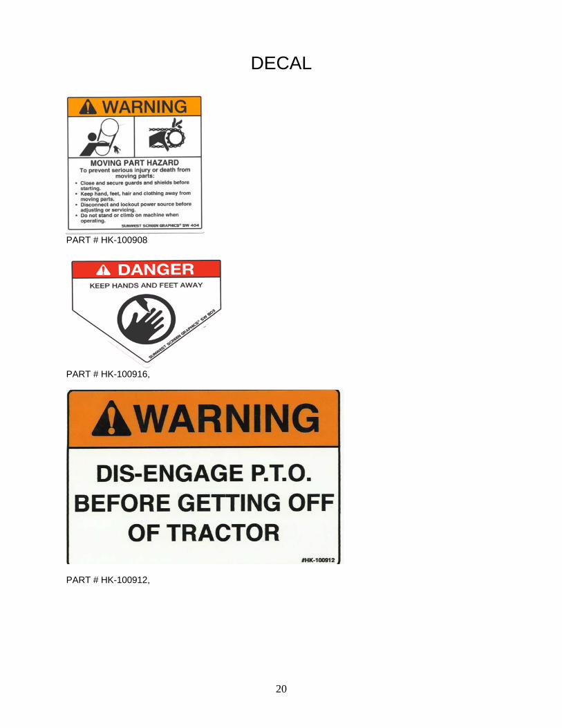
DECAL
PART # HK-100908
PART # HK-100916,
PART # HK-100912,

21
SAFTEY DECALS
PART # DB-400166,
PART # HK-100919,
SP-200157 HK-101853
PB-800852

22
PARTS
1 PB-800400 VOLUTE 2 PB-800011 FAN ASSEMBLY 3 PB-800034 FRONT GUARD 4 PB-800030 REAR GUARD 5 HK-101827 MANUAL CANISTER 6 PB-800010 DRIVE SHAFT 7 PB-800138 LIFT ARM PIN (CAT-1)
3
1
4
6
2
5
7

23
1 PB-800070 FAN BEARING MOUNT 2 HW-804120G5 BOLT, CARIAGE 3/8-16NC X 3 LG 3 HW-804104G5Z BOLT, CARIAGE 3/8-16NC X 1 4 HW-301204TLZ NUT, TOP LOCK, 3/8-16NC 5 PB-800026 NUT, HEX, COUPLING, 3/8-16NC X 1-1/8LG 6 HW-301201TL NUT, TOP LOCK, 1/4-20 7 HW-200104G5 BOLT,HH, 1/4-20NC X 1 LG 8 PB-800053 FAN BEARING
1
8 5
3
2
4
7
6

24
ITEM PART # DESCRIPTION 1 HW-301206TL NUT, TOP LOCK, HEX, 7/16-14NC, ZINC
PLATED 2 PB-800140 CHAIN ADJUSTER 3 PB-800013 CHAIN KIT (69.5” #40 CHAIN, ONE
CONNECTING LINK) 4 PB-800014 CONNECTING LINK #40 ROLLER CHAIN 5 PB-800015 HALF LINK #40 ROLLER CHAIN 6 HK-101295 IDLER 7 PB-800030 SLIDE CYLINDER MOUNT 8 PB-800025 SPROCKET 9 HK-100389 MOUNT BEARING 10 PB-800064 FAN SHAFT
1
24
5
7
6
8
9
10
3

25
PART # DESCRIPTION 1 PB-800053 BEARING 2 PB-800025 SPROCKET 3 PB-800013 CHAIN KIT (69.5” #40 CHAIN, ONE CONNECTING LINK)
1
1
2
3

26
1 PB-800134 HYD. CYLINDER 2 PB-800130 SLIDE CYLINDER MOUNT 3 HW-301208SC NUT, STOVER LOCK, HEX, 1/2-13NC 4 HW-208112G5Z BOLT, HH, 1/2-13 X 2 5 PB-800132 SLIDE BOTTOM PLATE 6 PB-800133 SLIDE WEAR PLATE (2 REQUIRED) 7 PB-800019 90° ELBOW RESTRICTOR JIC TO PIPE 8 PB-800018 HOSE (108 LG) 9 PB-800023 HOSE (96 LG) 10 HK-100965 QUICK COUPLER 11 HK-100993 QUICK COUPLER CAP 12 PB-800024 RESTRICTOR JIC TO PIPE 13 HW-960415 NUT, HEX NYLON LOCK, 4,,, A-2 14 HW-960315 BOLT, HH, 4MM X 35MM, SS, A-2 15 HW-202108G8C BOLT, HH, 5/16-18 X 1-1/2 LG, G8 16 HW-301202TLZ NUT, TOP LOCK, H, 5/16-18NC 17 PB-800022 PORT ADAPTER 18 HK-101307 HYD. CYLINDER PIN 19 PB-800139 CHAIN MOUNT WELDMENT
5
1 2
4
6
3
7
8
10
11
13 14
12
15
16
9
17
18 19

27
1 HK-100551 FAN PULLEY 2 PB-800012 INPUT SHAFT PULLEY 3 PB-800020 FAN BELT 4 PB-800045 INPUT SHAFT 5 PB-800027 ADJUSTMENT BOLT 6 05-100835 ADJUSTMENT BRACKET 7 HK-100389 BEARING
3
1
2
4
6
5
7

28
1 HW-960212 HOSE CLAMP 9/16 – 1-1/16 2 HW-960210 HOSE CLAMP 3/8 – 7/8 3 PB-800661 3/4 FNPT PP BULKHEAD FITTING 4 SP-200126 JET AGITATOR 5 SP-200231 TANK STRAP BRACKET 6 PB-800503 TANK STRAP 60” LG 7 HW-204112G5ZF BOLT, HEX HEAD,3/8-16 X 2 LG, FULL THREAD 8 HW-301204TLZ NUT, TOP LOCK, 3/8-16 9 PB-800405 TANK 55 GAL 10 PB-800406 TANK CAP
4
103
1 2
6
5
8
7
9

29
ITEM PART # DESCRIPTION 1 PS-500002 ELECTRIC VALVE 2 PB-800664 90° ELBOW 3/4 NPT X 1/2 HOSE BARB 3 PS-500405 3/4 NPT X 3/4 HOSE BARB 4 PB-800663 BLACK PIPE (SHORT) 3/4 NPT X 3/4 NPT 5 HK-101439 BUSHING 3/4 NPT X 1/4 NPT 6 SP-200116 TEE 3/4 NPT X 3/4 NPT X 3/4 NPT 7 PB-800662 90° ELBOW 3/4 NPT X 3/4 HOSE BARB 8 PS-500021 GAUGE
6
8
7
4
5
2
1
3

30
ITEM PART # DESCRIPTION 1 6500C PUMP 2 PB-800625 BUSHING 3 PB-800662 90° ELBOW 3/4 NPT -3/4 HB
ITEM PART # DESCRIPTION 1 PB-800668 STRAINER 2 PB-800662 90° ELBOW 3/4 NPT X 3/4 HOSE BARB 3 HK-100772 NIPPLE STEEL 3/4 NPT X 3/4 NPT 4 SP-200090 BALL VALVE 3/4 NPT X 3/4 NPT 5 PB-800676 SCREEN 6 CP23173-EPR (VI) LINE STRAINER WASHER
4
2 31
2
1
2
3
3
6 5
31
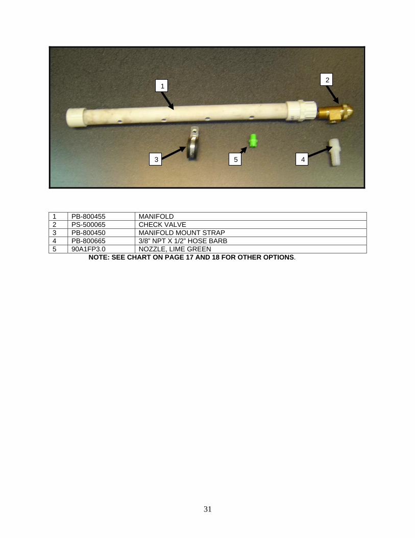
1 PB-800455 MANIFOLD 2 PS-500065 CHECK VALVE 3 PB-800450 MANIFOLD MOUNT STRAP 4 PB-800665 3/8” NPT X 1/2” HOSE BARB 5 90A1FP3.0 NOZZLE, LIME GREEN
NOTE: SEE CHART ON PAGE 17 AND 18 FOR OTHER OPTIONS.
1 2
3 5 4

32
1 PB-800652 HOSE, TANK TO FILTER, 3/4” X 15-1/4 LG 2 PB-800651 HOSE, FILTER TO PUMP, 3/4” X 38” LG 3 PB-800653 HOSE, PUMP TO GAUGE, 3/4” X 45” LG 4 PB-800654 HOSE, GAUGE TO AGITATOR, 3/4” X 23” LG 5 PB-800656 HOSE, ELECTRIC VALVE TO SPRAY TIPS, 1/2” X 78” LG
1
2
3
4
5