march 2016 illinois state toll highway authority
TRANSCRIPT

Guidelines for Roadway Illumination
March 2016
ILLINOIS STATE TOLL HIGHWAY AUTHORITY

ILLINOIS TOLLWAY GUIDELINES FOR ROADWAY ILLUMINATION
These Guidelines for Roadway Illumination revised March 2016 supersedes the previously issued version dated March 2015. Major Highlight Revisions
Illumination Design:
• Article 5.5: Revised to include circuit breakers, terminal blocks and surge protection devices within the junction box for underpass lighting feeds. This replaces the previous fuses and fuse holders.
• Article 7.4: Revised to include minimum mounting heights beneath toll plaza canopies.
• Article 7.5: Revised to include guidance on the implementation of LED lighting technology beneath toll plaza canopies.
• Article 7.7: Revised to include target illumination levels for beneath toll plaza canopies.
• Article 7.10: Revised overhead sign lighting typical luminaire spacing description.
• Article 7.11: Revised Typical Design Spacing Tables (Mainline & Ramps) as appropriate for updated photometric packages as provided by luminaire Manufacturers.
• Article 7.11: Revised Typical Design Spacing Tables (Mainline & Ramps) to include Philips underpass luminaires.

ILLINOIS TOLLWAY GUIDELINES FOR ROADWAY ILLUMINATION
Page Intentionally Blank

ILLINOIS TOLLWAY GUIDELINES FOR ROADWAY ILLUMINATION
TABLE OF CONTENTS
1.0 INTRODUCTION .................................................................................................. 1 1.1 Objective ............................................................................................................... 1 1.2 Application ............................................................................................................. 1 1.3 General .................................................................................................................. 1 1.4 Standards .............................................................................................................. 2
2.0 BASIC REQUIREMENTS .................................................................................... 5 2.1 Design Data ........................................................................................................... 5 2.2 Standard Drawings ................................................................................................ 5 2.3 Codes and Ordinances .......................................................................................... 5 2.4 Standards and Recommendations ........................................................................ 6 2.5 Specifications ........................................................................................................ 6 2.6 Suggested Electrical Pay Items ............................................................................. 7
3.0 REQUIRED SERVICES ....................................................................................... 9 3.1 General .................................................................................................................. 9 3.2 Design Concept ..................................................................................................... 9 3.3 Preliminary Design .............................................................................................. 11 3.4 Pre-Final Design .................................................................................................. 12 3.5 Final Design ........................................................................................................ 12
4.0 DRAWING REQUIREMENTS ............................................................................ 13 4.1 Working Drawings ............................................................................................... 13 4.2 Drawings ............................................................................................................. 14 4.3 Notes ................................................................................................................... 14 4.4 References .......................................................................................................... 15 4.5 Wiring Layout ...................................................................................................... 15
5.0 WIRING DESIGN ............................................................................................... 17 5.1 General ................................................................................................................ 17 5.2 Electrical Service & Lighting Controller ............................................................... 17 5.3 Temporary Lighting ............................................................................................. 18 5.4 Circuit Distribution ............................................................................................... 18 5.5 Circuit Conductors ............................................................................................... 19 5.6 Voltage Drop Calculations ................................................................................... 20 5.7 Equipment Grounding ......................................................................................... 20 5.8 Static Grounding .................................................................................................. 21
6.0 INFRASTRUCTURE DESIGN ............................................................................ 23 6.1 General ................................................................................................................ 23 6.2 Conduit ................................................................................................................ 23
March 2016 i Illinois Tollway

ILLINOIS TOLLWAY GUIDELINES FOR ROADWAY ILLUMINATION
6.3 Expansion/Deflection Fittings .............................................................................. 24 6.4 Handholes ........................................................................................................... 24 6.5 Junction Boxes .................................................................................................... 24 6.6 Lighting Standard Foundations ........................................................................... 24 6.7 Lighting Standards .............................................................................................. 25 6.8 Lighting Controller Foundations........................................................................... 29
7.0 ILLUMINATION DESIGN ................................................................................... 31 7.1 General ................................................................................................................ 31 7.2 Illinois Tollway Typical Roadway Sections .......................................................... 31 7.3 Luminaire/Light Standard Placement .................................................................. 33 7.4 Mounting Heights ................................................................................................ 34 7.5 Luminaire Types .................................................................................................. 35 7.6 Luminaire Classifications ..................................................................................... 38 7.7 Target Illumination Levels ................................................................................... 39 7.8 Light Loss Factor (LLF) ....................................................................................... 40 7.9 Underpass Illumination ........................................................................................ 41 7.10 Overhead Sign Structure Illumination .................................................................. 42 7.11 Typical Design Spacing Tables ........................................................................... 43
8.0 SPECIAL PROVISIONS ..................................................................................... 49 8.1 General ................................................................................................................ 49 8.2 Specifics .............................................................................................................. 49 8.3 Excavation Backfill and Concrete ........................................................................ 49
9.0 LED LUMINAIRE APPROVAL GUIDELINES .................................................... 51
March 2016 ii Illinois Tollway

ILLINOIS TOLLWAY GUIDELINES FOR ROADWAY ILLUMINATION
1.0 INTRODUCTION
1.1 Objective
The objective of these Guidelines is to obtain bidding documents which will provide roadway illumination of the highest quality (consistent with traffic safety requirements) and maximum system reliability at a minimum of maintenance and operating cost. Consequently, the information contained herein shall be reviewed and utilized by the Designer to meet the needs of each specific project.
1.2 Application
The information contained herein is applicable to all projects which include roadway lighting operated and maintained by the Illinois Tollway. The projects may include replacement of existing roadway lighting systems, replacement or modification of roadway lighting systems as part of a roadway widening, rehabilitation or interchange improvement, and projects for new construction.
1.3 General
Designer – The person (or consultant team) responsible for performing a design task for an Illinois Tollway project. Although this is typically the Design Section Engineer (DSE), it can also include a person (or consultant team) hired by a Contractor to perform design as part of a Value Engineering Proposal or part of a Performance Based Design. This document will use the term “Designer” which covers anyone performing design and will only use the term “DSE” when discussing tasks specific to the DSE. Refer to the Design Section Engineer’s Manual for more information.
This document has been prepared to provide the Designer, engaged in the design of new installations or the modification of existing facilities for the Illinois State Toll Highway Authority (Illinois Tollway), with the necessary information to design the roadway illumination (lighting) system for the project. The intent of this document is twofold:
• To provide design guidelines for illumination of roadways operated and maintained by the Illinois Tollway.
• To describe the scope of Professional Services required and expected from the Designer under their agreement with the Illinois Tollway for the development of the project design including the preparation of drawings, special provisions and cost estimates as they relate to roadway lighting.
These Guidelines have been developed with consideration to energy conservation. However, the intent is that such conservation shall not be obtained by compromising the minimum desirable illumination levels as recommended by the latest edition of the “American Standard Practice for Roadway Lighting” (ANSI/IESNA RP-8) and the AASHTO Roadway Lighting Design Guide. These Guidelines cover materials and methods which the Illinois Tollway has found to be most desirable from the standpoint of system reliability and low maintenance cost.
March 2016 1 Illinois Tollway

ILLINOIS TOLLWAY GUIDELINES FOR ROADWAY ILLUMINATION
These Guidelines are not intended to cover all details of planning, design, specifications and/or construction and are not intended to be inflexible to the extent of restraining progress and improvement of methods, selection and use of materials and economy of construction. It is recognized that no set of policies, however comprehensive, can replace sound engineering judgment and experience. Each project shall be considered individually with respect to its design. However, any deviations from the illumination design criteria contained herein shall be approved by the Illinois Tollway. In the event of conflict between the requirements of this document and requirements established by the Illinois Tollway in the Scope of Design Work for the specific project, the latter shall govern.
Notwithstanding any review, acceptance or approval by the Illinois Tollway, the Designer shall be responsible for ensuring the technical adequacy and economy of construction of the total design.
1.4 Standards
As a minimum, the most current version of the following industry standards and design guides shall apply to the design and construction of roadway lighting systems under the jurisdiction of the Illinois Tollway:
1. American National Standard Practice for Roadway Lighting, Publication ANSI/IES
RP-8, approved by the American National Standards Institute, published by Illuminating Engineering Society of North America
2. Roadway Lighting Design Guide, published by American Association of State Highway and Transportation Officials (AASHTO)
3. National Electrical Code, NFPA 70, National Fire Protection Association
4. National Electrical Safety Code, approved by the American National Standards Institute,
5. National Electrical Safety Code, Publication #ANSI/C2, published by the Institute of Electrical and Electronics Engineers (IEEE).
6. Standard Specifications for Structural Supports for Highway Signs, Luminaires and Traffic Signals, AASHTO Publication.
7. OSHA, Electrical Systems, Subpart 5, Part 1910 of Title 29 of the Code of Federal Regulations.
8. Professional Engineering Practice Act of 1989 [225 ILCS 325].
9. Standard Specifications for Road and Bridge Construction (Standard Specifications), published by State of Illinois Department of Transportation (IDOT).
10. Supplemental Specifications and Recurring Specifications, published by IDOT.
11. Illinois Tollway Supplemental Specifications to the IDOT Standard Specifications.
March 2016 2 Illinois Tollway

ILLINOIS TOLLWAY GUIDELINES FOR ROADWAY ILLUMINATION
12. IDOT Highway Standards.
13. Illinois Tollway Standard Drawings.
14. IDOT Bureau of Design and Environment (BDE) Manual, Chapter 56 on Highway Lighting, as applicable.
15. Insulated Cable Engineers Association and Underwriters Laboratories publications when applicable for cable and other materials.
16. National Electrical Manufacturers Association (NEMA) standards, where applicable.
17. American National Standards Institute (ANSI) standards where applicable, for lamps,
ballasts, and other accessories.
18. American Society for Testing and Materials (ASTM) standards for materials.
19. Manual on Uniform Traffic Control Devices, published by the FHWA and the Illinois MUTCD.
March 2016 3 Illinois Tollway

ILLINOIS TOLLWAY GUIDELINES FOR ROADWAY ILLUMINATION
Page Intentionally Blank
March 2016 4 Illinois Tollway

ILLINOIS TOLLWAY GUIDELINES FOR ROADWAY ILLUMINATION
2.0 BASIC REQUIREMENTS
2.1 Design Data
Available existing roadway plans, profiles and geometric details forming the basis for the assigned project shall be provided to the Designer by the Illinois Tollway for their use in the preparation of contract drawings. However, these documents shall be carefully checked, updated and revised as necessary to reflect the as-built or current conditions by the Designer.
For projects involving roadway widening, interchange improvements or new roadway construction, the plans, profiles and geometric details developed by the Designer shall form the basis for the design of the roadway lighting system. On some projects the Designer responsible for the roadway lighting system may be different than the Designer for the roadway geometric design. On such projects the Designer for each discipline shall be responsible for coordination of their work with the work of other Designers to provide the Illinois Tollway with bidding documents as defined in the Scope of Design Work for the project.
2.2 Standard Drawings
The Illinois Tollway has prepared Standard Drawings which are available to the Designer. These Standard Drawings include typical details such as light standard (pole) foundations, junction boxes, control consoles, wiring diagrams, etc. to facilitate the preparation of working drawings. In many cases, these standard drawings supersede the IDOT Highway Standards for the items detailed within. The Illinois Tollway Standard Drawings are not intended to provide for all design conditions that may be encountered by the Designer. The Designer is responsible for verifying that the Illinois Tollway Standard Drawings are applicable to the specific design requirements of their project.
The Designers shall familiarize themselves with the Illinois Tollway Standard Drawings and the IDOT Highway Standards. The Illinois Tollway Standard Drawings shall govern the work except as amended or superseded by the Designer for a specific project or application and incorporated into the Contract Documents as specified in the DSE Manual.
2.3 Codes and Ordinances
It is the intent of the Illinois Tollway that all electrical design and construction comply with all applicable national and local codes and ordinances and particularly with the following:
• National Electrical Code (NEC)
• National Electrical Safety Code (NESC)
• Occupational Safety and Health Administration (OSHA)
March 2016 5 Illinois Tollway

ILLINOIS TOLLWAY GUIDELINES FOR ROADWAY ILLUMINATION
2.4 Standards and Recommendations
Unless otherwise indicated in these Guidelines, the design, drawings and specifications shall incorporate and specify only approved methods, materials, equipment, devices, luminaires and machinery which comply with the current standards and/or recommendations of the following organizations:
• National Electrical Manufacturers Association (NEMA)
• Institute of Electrical and Electronic Engineers (IEEE)
• Illuminating Engineering Society of North America (IESNA)
• American Association of State Highway and Transportation Officials (AASHTO)
• U. S. Department of Transportation
• Underwriters Laboratories, Inc. (UL)
• American National Standards Institute (ANSI)
2.5 Specifications
The Designers shall familiarize themselves with the Illinois Department of Transportation (IDOT) current Standard Specifications for Road and Bridge Construction, current IDOT Supplemental Standard Specifications, and Illinois Tollway Supplemental Specifications herein referred to in their entirety as the “Standard Specifications”. These Standard Specifications shall govern the work except as amended by the Special Provisions prepared by the Designer for a specific project and incorporated into the Contract Documents. The Illinois Tollway Supplemental Specifications are modifications to the IDOT Standard Specifications for Road and Bridge Construction. These Supplemental Specifications often limit the types of materials to be utilized on Illinois Tollway Projects to facilitate maintenance. The Designer shall adhere to the Illinois Tollway Supplemental Specification to the greatest extent possible. Deviations to the requirements set forth in the Illinois Tollway Supplemental Specifications or the IDOT Standard Specifications shall be approved by the Illinois Tollway prior to the Designer preparing the required Special Provision. Care shall be exercised to prevent repetition of or conflict with the Standard Specifications. The Special Provisions shall follow the format prescribed by the Illinois Tollway.
March 2016 6 Illinois Tollway

ILLINOIS TOLLWAY GUIDELINES FOR ROADWAY ILLUMINATION
2.6 Suggested Electrical Pay Items
A listing of Illinois Tollway approved suggested electrical pay items to be utilized for the design of roadway lighting systems on the Illinois Tollway is provided to the Designer at the commencement of the design. If this list is not provided, the Designer is to request the current listing from the Illinois Tollway Project Manager. These pay items limit the types of materials to be utilized on Illinois Tollway Projects. Items listed that require Special Provisions have the designation DSE in the Special Provision column. This list does not contain all material that may be required for a roadway lighting project within the jurisdiction of the Illinois Tollway. The Designer shall identify any additional pay items required for their design which are not included in the Illinois Tollway approved list and obtain Illinois Tollway approval to utilize these additional pay items. If a new pay item requested for use by the Designer is covered by an IDOT Standard and there is a published IDOT Standard code number, the Illinois Tollway may approve the use of the material without the requirement of a Special Provision. If the item is defined by the Illinois Tollway Supplemental Specifications the Illinois Tollway shall assign a new code number. If the pay item is not adequately defined by the IDOT Standards or the Illinois Tollway Supplemental Specifications the Designer shall provide a Special Provision to define the work and the Illinois Tollway shall provide a code number for the new pay item. The Illinois Tollway may, at their discretion, provide the Designer a sample Special Provision from another Contract to facilitate their work.
March 2016 7 Illinois Tollway

ILLINOIS TOLLWAY GUIDELINES FOR ROADWAY ILLUMINATION
Page Intentionally Blank
March 2016 8 Illinois Tollway

ILLINOIS TOLLWAY GUIDELINES FOR ROADWAY ILLUMINATION
3.0 REQUIRED SERVICES
3.1 General
The extent and types of services to be performed by the Designer in the execution of their contractual obligations are hereinafter defined in more detail. Construction inspection shall be performed under a separate contract for Construction Manager’s Services.
3.2 Design Concept
The Designer shall study roadway and signing layouts and investigate various illumination alternatives in accordance with these criteria, including methods and locations of supplying the necessary electric service. For the design concept, the Designer shall submit to the Illinois Tollway a Concept Design Report including:
a. A narrative to include the following: i. Discussion of the design approach and alternatives considered. ii. Discussion and description of the lighting layout being recommended. iii. Summary of recommended spacing for each project typical roadway section
(including ramps and underpasses) including description of light standards recommended. The description shall at a minimum include the recommended mounting height, mast arm length(s), luminaire type, and luminaire distribution type.
b. Project specific typical roadway sections complete with identification of station limits for each.
c. Luminaire Manufacturers’ descriptive literature with ordering number and photometric characteristics identified as applicable in each case.
d. Comparative cost data for each alternative presented. e. Lighting system layout plan indicating location, mounting height, mast arm length(s),
luminaire type, and photometric distribution type for the recommended layout. f. Computer generated photometric calculations shall be submitted for all following
conditions: i. Toll plaza approaches and departures ii. Complex gore areas iii. Mainline and/or underpass configurations not covered by the Illinois Tollway
Typical Roadway Sections described herein and the Typical Design Spacing Tables provided herein.
g. Computer generated photometric calculations shall be performed as follows: i. Photometric calculations shall be performed using a “R3” pavement classification
regardless of actual pavement. ii. Photometric calculation “grid” parameters shall conform to the requirements of
ANSI/IESNA RP-8 whenever possible. The following information shall be provided:
1. Grid Location (x,y) 2. Spacing of calculation points (longitudinal & transverse) 3. Number of lanes
March 2016 9 Illinois Tollway

ILLINOIS TOLLWAY GUIDELINES FOR ROADWAY ILLUMINATION
4. Direction of luminance calculations iii. Photometric calculations shall include calculation input parameters including:
1. Luminaire Manufacturer 2. Lumens Used 3. Luminaire Mounting Height 4. Set Back 5. Luminaire Location 6. Luminaire Tilt 7. Luminaire Photometric Filename 8. Light Loss Factor 9. Mast Arm Length 10. Pole Location 11. Luminaire Orientation 12. Lamp Type
iv. Photometric calculations shall be performed for each layout provided utilizing all Illinois Tollway approved luminaires listed in the typical design standard spacing tables provided herein.
v. The photometric calculations for mainline, ramps and underpasses shall at a minimum include results for:
1. Illuminance: • Average (foot-candles) • Average : Minimum Uniformity Ratio
2. Luminance: • Average (cd/m2) • Average : Minimum Uniformity Ratio • Maximum : Minimum Uniformity Ratio • Maximum Veiling Luminance : Average Luminance Ratio
vi. The photometric calculations for toll plaza approaches/departures and complex gore areas shall at a minimum include results for:
1. Illuminance: • Average (foot-candles) • Average : Minimum Uniformity Ratio
vii. A luminaire performance comparison table shall be provided for each layout to ensure the proposed design layout will be sufficient with all Illinois Tollway approved manufacturers.
viii. A summary table of photometric calculation results shall be provided for quick reference.
ix. All photometric calculations shall be performed utilizing AGI32 software. NOTE: For areas void of continuous mainline lighting, all interchanges within the project limits shall at a minimum include partial interchange lighting consisting of units along the outside shoulder of all interchange ramps from a point within 50 feet from the point of taper with the mainline to the terminus of Illinois Tollway jurisdiction at the crossroad intersection. The Designer shall evaluate all interchanges within the project limits to determine warrant for Full Interchange Lighting as defined in the latest revisions of the AASHTO Roadway Lighting Design Guide. This evaluation shall be included in the Concept Design Report and shall include recommendations for the implementation of Full Interchange Lighting, if found to be warranted. The Illinois Tollway shall review the Concept Design Report. After review, the Designer shall develop the construction plans from the approved concept.
March 2016 10 Illinois Tollway

ILLINOIS TOLLWAY GUIDELINES FOR ROADWAY ILLUMINATION
3.3 Preliminary Design
The Designer shall develop working drawings of the Illinois Tollway approved concept upon receipt of the Illinois Tollway’s design concept review comments. The preliminary design submittal shall be at approximately 60% design completion stage. Minimum requirements for preliminary design submittal shall be as follows:
a. Working drawings of the approved concept indicating: i. Lighting system layout indicating light standard location, mounting height, mast
arm length(s), luminaire type, photometric distribution type, and circuiting. ii. All conduit and cable sized and labeled. iii. All conduit casings and junction boxes identified and located. iv. All construction details identified. v. All standards identified vi. All lighting controllers identified and located. vii. Electrical services identified and located. viii. All demolition work identified. ix. All temporary lighting work identified.
b. Voltage drop calculations for each circuit for verification of cable sizing. c. Updated illumination calculations addressing any comments from the concept submittal
or revisions required due to new geometry. d. Draft special provisions. e. Preliminary estimate of pay items and quantities. f. Documentation of coordination with utilities for new or relocated services. g. Load calculations for each circuit and overall electric service presented in a panel
schedule format. h. Grounding scheme showing proper system grounding and proper equipment
grounding/bonding in conformance with NEC requirements. i. Single line/wiring diagram of the lighting system which identifies each lighting standard
lighting controller, electric service, and cable and conduit from electrical utility service to the end of each circuit.
The Illinois Tollway shall review the preliminary design documents and provide review comments to the Designer. At this stage of plan development, when identified in the Scope of Design Work, the Designer shall stake out the proposed light standards in the field for the purpose of a plan-in-hand field review. If a plan-in-hand field review is not required by the Scope of Work the Designer shall still perform a field review to verify there are no obstructions to the proposed work such as overhead power lines or drainage culverts.
March 2016 11 Illinois Tollway

ILLINOIS TOLLWAY GUIDELINES FOR ROADWAY ILLUMINATION
3.4 Pre-Final Design
The Designer shall resume development of the contract documents upon receipt of the Illinois Tollway’s preliminary design review comments. Upon completion of the contract plans, the Designer shall submit the working drawings, Special Provisions, design calculations and estimate of quantities. The pre-final submittal shall be 95% complete. If any information requiring Illinois Tollway direction is lacking, the item shall be noted in the Designer’s transmittal letter.
The Designer shall provide a narrative report of their plan-in-hand field review discussing and issues and/or conflicts identified with the proposed work any items such as overhead power lines, underground utilities, or drainage culverts. The Illinois Tollway shall review the pre-final design documents and provide review comments to the Designer.
3.5 Final Design
The Designer shall complete development of the contract documents upon receipt of the Illinois Tollway’s pre-final design review comments. After all corrections to the Plans and Special Provisions have been made, the final estimate of quantities shall be submitted to the Illinois Tollway together with contract documents as outlined in the current Illinois Tollway CADD Standards Manual.
March 2016 12 Illinois Tollway

ILLINOIS TOLLWAY GUIDELINES FOR ROADWAY ILLUMINATION
4.0 DRAWING REQUIREMENTS
4.1 Working Drawings
On projects that include only roadway lighting, working drawings shall be organized in the following sequence:
• Cover Sheet with Location and Vicinity Maps
• General Notes, Symbols, Legends, Index of Drawings, Progress Schedule
• Summary of Quantities
• Maintenance of Traffic
• Detail Plans and/or Elevations
• Details, Wiring Diagrams and Schedules
• Cross-sections (if applicable) On projects that include roadway lighting as part of a larger improvement, the roadway lighting working drawings shall be organized in the following sequence:
• Index of Drawings, Progress Schedule, and Summary of Quantities (to be incorporated and coordinated with the other disciplines)
• General Roadway Lighting Notes, Symbols and Legends
• Detail Plans and/or Elevations
• Details, Wiring Diagrams and Schedules
• Cross-sections (if applicable) A Bill of Material for roadway lighting is not required to be included in the drawings however, quantity calculations shall be provided that verify the quantities for all roadway lighting pay items included in the Project Summary of Quantities. On projects that include roadway lighting systems of both Illinois Tollway and IDOT or another Agency, the Illinois Tollway roadway lighting drawings shall be separate from other roadway lighting drawings and shall be placed first in the drawing set. Where Illinois Tollway and non-Illinois Tollway lighting appears on the same drawing; the line work, symbols, notes, and callouts shall clearly differentiate between the two systems. The roadway lighting drawings for systems not under the jurisdiction of the Illinois Tollway shall be reviewed by the Agency having jurisdiction for the system.
March 2016 13 Illinois Tollway

ILLINOIS TOLLWAY GUIDELINES FOR ROADWAY ILLUMINATION
4.2 Drawings
Drawings shall follow the requirements of the current ICAPP Manual and Design Bulletins. Backgrounds prepared for the layout of roadway lighting work shall be CADD generated geometric facsimiles of roadway design drawings. They shall include all known existing and proposed utilities including but not limited to water, gas, sewer, electric, toll collection and communication lines that either cross over or under or run parallel in close proximity to the proposed lighting work. Surface structures, such as buildings, hydrants, signs, crash barriers, trees, etc. within the Illinois Tollway right-of-way in any areas of proposed lighting work shall also be shown. Line work shall conform to the requirements set forth for Roadway Lighting in the ICAPP Manual. Roadway lighting symbols shall utilize the cells included in the Civil Cell Library contained in the ICAPP Manual. All symbols used shall be shown on a drawing together with the General Notes, etc. Each light standard shall be indicated as follows:
S15-50-C4 STA. 0+20 Distribution
Where STA. 0+20 is the station of the light standard,
S15-50-C4 is the mast arm quantity (S for single, D for double), mast arm length, mounting height and circuit number, and
Distribution is the Photometric Distribution types per the Typical Design Spacing Tables provided herein
It is generally preferred that conduit and wiring be identified using symbols rather than by lengthy descriptions. All conduit and cable shall be identified. Symbol legend shall be shown on each drawing where symbols are used. One set of symbols shall be used throughout the Contract Documents. An example of a symbol legend is as follows:
2” UNIT DUCT, 4-1/C NO. 2 & 1-1/C NO. 4 GROUND, 600 VOLT (XLP-TYPE USE)
4.3 Notes
Notes relating to work appearing on a particular drawing shall be shown on that drawing only and not in the General Notes. The General Notes shall contain information applicable to work on all drawings or the work in general. Notes shall only appear on a particular drawing (with the exception of the General Notes) if they are specifically applicable to the work shown on that drawing.
A
March 2016 14 Illinois Tollway

ILLINOIS TOLLWAY GUIDELINES FOR ROADWAY ILLUMINATION
4.4 References
Other drawings which define the work of other disciplines in the same areas shown on the roadway lighting plans shall be referenced by their given drawing number on each related roadway lighting drawing together with references to other roadway lighting drawings or details as necessary.
4.5 Wiring Layout
All wiring of roadway lighting electrical systems shall be single line. Stationing of poles, light standards, junction boxes, etc. shall be in agreement with stationing appearing on roadway design plans. Temporary work, when possible, shall appear on the same plans as the demolition work. Lighting at interchanges shall utilize two circuits per quadrant. All roadway lighting shall be on alternating circuits. Luminaires on twin mast arm median light standards shall be on two circuits and circuits shall alternate between the light standards for each direction of travel. Mainline and ramp lighting shall have not less than two circuits with alternate lights on each circuit.
March 2016 15 Illinois Tollway

ILLINOIS TOLLWAY GUIDELINES FOR ROADWAY ILLUMINATION
Page Intentionally Blank
March 2016 16 Illinois Tollway
ILLINOIS TOLLWAY GUIDELINES FOR ROADWAY ILLUMINATION
5.0 WIRING DESIGN
5.1 General
The Designer shall provide a complete wiring system, covering all aspects of the project. The design shall take into consideration the adequacy, dependability, regulation and available fault current of the supply source.
5.2 Electrical Service & Lighting Controller
On all projects requiring new or increased capacity electrical services from an electric utility source, the Designer shall make the initial contact with the electric utility company and assist the Illinois Tollway in negotiating the necessary electrical service contracts. The Designer shall provide all necessary load data, system service equipment requirements and other pertinent information which may be required by the electric utility to furnish adequate and appropriate electrical service facilities. The Designer shall verify that the electric utility company is able to provide electrical service at the selected location before proceeding with the design of the wiring system.
The secondary service for roadway lighting service shall be 240/480 volt, 3-wire, single phase, 60 Hertz, grounded. The service, including transformers when required, shall be of sufficient capacity to accommodate the connected load plus 20 percent for load expansion with a maximum 2 percent voltage drop at 100 percent demand factor. All electrical services shall consist of the necessary incoming supply conductors, transformers, meter, and main disconnect switch for a complete installation complying with utility and code regulations.
Proposed modifications or additions made to an existing installation shall require that the Designer determine the adequacy and condition of the existing electrical service and distribution equipment for safely carrying the resultant load. Where these are found to be inadequate or in an unsatisfactory condition, the Designer shall make the necessary changes to accommodate the resultant connected load plus 20 percent for load expansion.
All lighting controllers shall be a 200 ampere type in accordance with the Illinois Tollway Standard Specifications and Drawings of the installation type (outdoor or indoor) specified.
All new roadway lighting controller installations shall be metered and shall be provided with an electrical utility meter housing and meter unless otherwise specified by the Illinois Tollway.
As often as reasonably possible, all new roadway lighting controllers shall be located within Illinois Tollway buildings or facilities in conformance with the Illinois Tollway Standard Drawings. On all projects including existing lighting controllers which are either associated with the construction or rehabilitation of or is in the vicinity of Illinois Tollway buildings and/or facilities, the Designer shall examine the feasibility of replacing the existing external lighting controller(s) with one located within the facility. On any project including the installation of a lighting controller either within or adjacent to a Illinois Tollway building or facility, the Designer shall coordinate the space requirements for the roadway lighting electrical service transformer and roadway lighting controller with the Designer
March 2016 17 Illinois Tollway

ILLINOIS TOLLWAY GUIDELINES FOR ROADWAY ILLUMINATION
of the facility. In general, the roadway lighting electrical service transformer shall be located near the facility electrical service transformer to minimize utility service costs. In all cases, the roadway lighting electrical service shall be separate from the facility electrical service. All electrical service transformers shall be owned and maintained by the electric utility company. At all locations which the lighting controller is installed within an Illinois Tollway building or facility, the electrical meter housing and meter shall be located on an external building wall. At locations where the meter housing may not be mounted to a building exterior wall and for all external lighting controller installations, the electrical meter housing and meter shall be located on a service pedestal located on Illinois Tollway property near the right-of-way fence. The location of the service pedestal shall be accessible to the electric utility company meter reader and be near the utility service pole. A man way gate, suitable for padlocking, shall be provided in the right-of-way fence at each service pedestal location to facilitate access by the electric utility company. Padlocks shall be provided by the utility company.
5.3 Temporary Lighting
The Designer shall identify the need for temporary roadway lighting and provide the design for temporary roadway lighting facilities and wiring required to maintain continuous operation and illumination integrity of the existing roadway lighting systems while construction modifications to the systems are in progress. This includes the design and specification of temporary lighting systems wherever the construction staging of the project dictates that the existing lighting system requires modification or removal. This work shall be coordinated with the roadway Designer and the extent of the proposed temporary lighting system on a project shall be addressed in the Preliminary submittal. All modification work on existing systems shall comply with the criteria and specifications in these Guidelines unless otherwise approved by the Illinois Tollway. NOTE: Due to the lack of crash test information, the connection of temporary aerial cables to ground mounted lighting units which are not shielded by guardrail or barrier is prohibited on the Illinois Tollway system. In instances where such a lighting unit must be powered by temporary wiring, this wiring shall be routed to the lighting unit underground in a raceway and sliced in the light pole.
5.4 Circuit Distribution
Branch circuit distribution shall be provided from a roadway lighting controller conforming to the requirements of the Standard Specifications and Drawings. Each 480 volt roadway lighting circuit shall be protected by a 40 ampere, 2-pole branch circuit breaker located in a 480 volt, 2-wire, single phase distribution panelboard included as part of the roadway lighting controller. The initial load on the 200 ampere roadway lighting controller shall not exceed 140 amperes to allow for future expansion. Circuit breakers shall be rated 600 volt. A minimum of four 2-pole circuit breakers shall be included in each roadway lighting controller as spares.
At toll plazas, the first lighting unit on each side of the roadway on both the approach and departure sides of the plaza shall be connected to the standby generator of the plaza via the canopy lighting panel. The Illinois Tollway also requires the lighting units for employee parking lots be placed on the standby power system. At plazas where the service voltage is 120/208
March 2016 18 Illinois Tollway

ILLINOIS TOLLWAY GUIDELINES FOR ROADWAY ILLUMINATION
volts, a step-up power transformer will be required to step-up to the luminaire operating voltage of 480 volts.
5.5 Circuit Conductors
Roadway lighting branch circuit conductors shall be sized for a connected load with voltage drop not exceeding 3 percent from the lighting controller. All branch circuit conductors shall be a minimum No. 8 AWG and a maximum No. 2 AWG. All control wiring shall be No. 12 AWG minimum. The minimum size for above grade conductors (i.e. power for underpass lights) shall be No. 10 AWG. Continuously energized circuits supplying flashing beacon lights, video equipment or other ancillary equipment (120 or 480 volts) shall be routed in separate raceway systems installed in parallel with roadway lighting raceways. The design shall be based on the use of copper conductors. Aluminum conductors shall not be used except for temporary aerial connections. Conductor splices shall be made only within accessible above grade locations such as within pole bases, junction boxes and within enclosures. Below grade conductor splicing is strongly discouraged for Illinois Tollway owned systems. In the event a below grade splice cannot be avoided, the splices shall be waterproof of the epoxy encapsulated type. Wiring layout design should preclude the need for grade-level handholes, junction boxes or pull boxes to the extent possible. In no cases are conductor splices permitted in conduit or ducts. Conduits may be spliced using appropriate materials and methods where needed to facilitate the relocation of the element being powered; however, the conductors from point to point shall be continuous, without splices. Power conductors shall be 600 volt, cross-linked polyethylene (XLP) insulated, type RHH/RHW-2/USE-2. The cable shall meet or exceed the requirements of ICEA S-95-658, NEMA Standard Publication WC-70 and UL Standard 44. Minimum insulation thickness at any point shall not be less than 90 percent of the average insulation thickness listed the tables for both aerial and non-aerial cable insulation, found in the IDOT Standard Specifications for Road and Bridge Construction.
• RHH = Thermoset Insulation, 90 degrees Celsius
• RHW-2 = Thermoset Insulation, 90 degrees Celsius, Moisture Resistant
• USE-2 = Underground Service Entrance, 90 degrees Celsius
A maximum of two (2) circuits shall enter each light standard. The color coding of the conductors shall be two (2) yellow conductors for circuit A and two (2) orange conductors for circuit B. An equipment ground conductor shall be routed with the power conductors in each raceway, unit duct or conduit run. Ground conductors shall be 600 volt; XLP insulated (green), type RHH/RHW-2/USE-2. Minimum size ground conductor run with roadway lighting conductors shall be No. 8 AWG.
March 2016 19 Illinois Tollway

ILLINOIS TOLLWAY GUIDELINES FOR ROADWAY ILLUMINATION
Pole wire, wiring to underpass luminaires and wiring to sign luminaires shall be No. 10 AWG for both power and ground. Conductors shall be 600 volt, XLP insulated, type RHH/RHW-2/USE-2. For underpass lighting circuits the primary roadway lighting circuit conductors shall be terminated in a wall mounted junction box. Circuit breakers, terminal block and surge protection devices shall be installed within the junction box and minimum No. 10 AWG conductors shall be utilized from the load side of the circuit breakers to the underpass luminaires. For roadways incorporating median light standards only, the underpass luminaires shall be fed from the same circuits as the median light standards and placed on alternating circuits. The wall mounted junction box mentioned above shall be mounted on the median bridge pier column. For roadways incorporating outside light standards only, the underpass luminaires shall be fed from the same circuits as the outside light standards and placed on alternating circuits. The wall mounted junction box mentioned above shall be mounted on the abutment wall.
5.6 Voltage Drop Calculations
The following loads shall be used when performing voltage drop calculations:
• 1 ampere for roadway luminaires (400 watt HPS or equivalent LED luminaires)
• 0.4 amperes for underpass luminaires (150 watt HPS or equivalent LED luminaires)
• 0.25 amperes for overhead sign structure luminaires (85 watt induction lamp or equivalent LED luminaires)
NOTE: Equivalent LED luminaires shall be comparable per illumination output measured on the target area when compared to HPS or induction lamp luminaires, not input wattage.
5.7 Equipment Grounding
All equipment shall be grounded and bonded in accordance with the NEC, using a continuous equipment grounding conductor throughout all wiring, properly bonded to poles, handholes, metallic collars, boxes, etc.
The earth shall not be considered as an equipment grounding conductor, i.e. equipment grounding conductor must be incorporated in all circuit runs and the equipment grounding conductor shall be an insulated conductor (green insulation color) run together with the circuit conductors in the same raceway (or, where direct-burial cable is permitted, the grounding conductor shall be part of the multi-conductor cable assembly). A bare grounding wire, run separate from the circuit conductors is not permitted. Continuity of grounding (bonding) conductors and equipment ground conductor shall not be dependent upon terminations at poles and other intermediate points. At such points, connections shall be made via a splice and pigtail.
March 2016 20 Illinois Tollway
ILLINOIS TOLLWAY GUIDELINES FOR ROADWAY ILLUMINATION
5.8 Static Grounding
Ground Rods shall be installed for electrical service grounding at service entrance locations. Roadway light standards and support posts for sign structures shall be solidly grounded to independent earth driven ground rods located adjacent to each unit. This grounding shall be provided in addition to any equipment grounding provided to lighting and equipment mounted on the standards, structures or posts. Elevated sign structures spanning roadways shall be grounded at the outside support column. Connections to all ground rods shall be with exothermic welds.
March 2016 21 Illinois Tollway

ILLINOIS TOLLWAY GUIDELINES FOR ROADWAY ILLUMINATION
Page Intentionally Blank
March 2016 22 Illinois Tollway

ILLINOIS TOLLWAY GUIDELINES FOR ROADWAY ILLUMINATION
6.0 INFRASTRUCTURE DESIGN
6.1 General
The Designer shall provide the necessary infrastructure for the installation of roadway lighting standards and circuit distribution, covering all aspects of the project. The design shall take into consideration the adequacy, dependability, and maintainability of the system.
6.2 Conduit
Rigid (heavy wall) galvanized steel conduit shall be used for all work on plaza canopy structures. PVC coated rigid steel or rigid stainless steel conduit shall be used for all above grade work attached to outdoor structures such as bridges and underpasses. Where conduit sleeves are installed in earth under roadways, they shall be Schedule 40 PVC conduit or Schedule 40 CNC (coilable non-metallic conduit). For a single 2-inch unit duct a minimum 4-inch conduit sleeve shall be provided. PVC coated rigid aluminum metal conduit shall only be used for wiring attached to aluminum portions of overhead sign structures. Unit duct shall be used for direct burial in earth outdoors for extensions of branch circuit conductors to lighting standards. Minimum size of unit duct shall be 2-inch. Raceways embedded in median and parapet walls shall be Schedule 40 PVC conduit or Schedule 40 CNC. The maximum size of raceways embedded in single face barrier wall or parapet walls shall be 2-inch. Where 2 inch unit duct is installed in median barrier a 4-inch minimum Schedule 40 PVC or CNC conduit sleeve shall be provided. Conduits embedded in barrier or parapet walls which stub-out to feed underpass lighting or sign truss lighting shall be rigid stainless steel conduit from the junction box embedded in the wall to the first structure mounted junction box or enclosure. Minimum size of this conduit shall be 1-1/2 inches. Conduits required to transition from a below grade conduit to a conduit above grade shall be rigid stainless steel conduit from a point below grade adjacent to the stub-up to the first structure mounted junction box or enclosure as indicated in the Standard Drawings. All outdoor underground installations, unless otherwise indicated on the contract drawings, shall be installed not less than 33 inches below finished grade, as indicated on the Standard Drawings. Unless specifically identified on the plans the Contractor shall have the option of installing underground raceways and unit ducts by trenching, plowing, or boring and pulling; except where boring and pulling is required beneath existing paved areas.
March 2016 23 Illinois Tollway

ILLINOIS TOLLWAY GUIDELINES FOR ROADWAY ILLUMINATION
6.3 Expansion/Deflection Fittings
Exposed and embedded conduits crossing structural expansion joints shall be provided with expansion or expansion/deflection type fittings as required. Exposed conduit runs exceeding 200 feet, which are attached to a structure, shall be provided with expansion/deflection type fittings. Expansion, deflection or expansion/deflection fittings shall be O.Z./Gendey Type AX, DX or AXDX respectively as required by anticipated movement. All expansion type fittings shall be identified on the contract plans.
6.4 Handholes
Handholes shall be provided in underground duct runs only where necessary to facilitate pulling, splicing and routing of conductors. They shall not be installed in duct runs between lighting standard foundations except where distances between light standard foundations exceeds 500 feet. Handholes shall not be located in shoulders or other paved areas without specific approval of the Illinois Tollway.
6.5 Junction Boxes
For roadways incorporating median barrier wall mounted light standards, stainless steel junction boxes embedded in the median barrier shall be provided as required. The size of junction boxes embedded in median barrier walls shall be 20” X 12” X 8”.
For roadways incorporating single face barrier wall or structural parapet wall mounted light standards, stainless steel junction boxes attached to the back of the barrier and/or parapet wall shall be provided as indicated on the Standard Drawings.
All surface mounted junction boxes installed outdoors shall be stainless steel and sized appropriately for the application.
For underpass locations where the incoming feeder to the underpass is routed to a median pier, the main service entrance junction box shall be installed four (4) feet above the top of the median barrier wall or pier crash wall.
6.6 Lighting Standard Foundations
Lighting standard foundations shall be provided as shown in the Illinois Tollway Standard Drawings where applicable for the conditions encountered in the project design. The Designer shall coordinate the grading requirements for all unshielded ground mounted lighting standards with the Project Roadway Designer. Designer shall verify the Illinois Tollway Standard Drawings, including all grading requirements, are applicable to the specific design conditions encountered. ASSHTO limits the projection of stub materials left after a pole breaks to four (4) inches. To achieve this, light pole foundations must be installed on a level surface with the top of the foundation (concrete or helix) flush with the surrounding grade. Grading requirements are shown on the most recent Illinois Tollway Standard H1. It is the responsibility of the Designer to confirm that the grading shown on the Standard Drawings can be implemented on the Project during design and to provide alternatives in the event it cannot.
March 2016 24 Illinois Tollway

ILLINOIS TOLLWAY GUIDELINES FOR ROADWAY ILLUMINATION
NOTE: If any installation(s) not conforming to these grading requirements are encountered within the limits of any type of project within the Illinois Tollway System, the Designer shall include these as part of the Barrier Warrant Analysis and provide recommendations/options to the Illinois Tollway to correct the issue.
6.7 Lighting Standards
Unless otherwise required, lighting standards complete with mast arms and luminaires shall be provided and located with respect to the roadway and on bridges as shown in the Illinois Tollway Standard Drawings. The Designer shall verify the Illinois Tollway Standard Drawings are applicable to the specific design conditions encountered. Specific attention shall be directed to the effect of vibration on bridge mounted light standards and location of light poles behind guardrail. Lighting standards shall be aluminum alloy material as shown on the Illinois Tollway’s Standard Drawings. Lighting standards installed in certain locations shall be provided with a breakaway base device. See below for typical locations requiring a breakaway base device:
• Mounted onto bridge or structural wall parapet walls: No breakaway base device
• Mounted to median or outside barrier walls: No breakaway base device
• Ground mounted behind bridge parapet walls: No breakaway base device
• Ground mounted & shielded by barrier or guardrail: Provide breakaway base device
• Ground mounted & unshielded: Provide breakaway base device At locations where pedestrian facilities exist such as at toll plazas, parking lots and accident investigation sites, the Designer shall evaluate the level of pedestrian traffic to determine if a breakaway base device would present a greater potential hazard to the pedestrian traffic than a non-breakaway pole would present to vehicular traffic. In these locations, ground mounted light poles may be installed without a breakaway base device based upon Designer engineering judgment. Breakaway devices shall be FHWA and AASHTO approved and shall be a transformer base type. There are five types of breakaway devices commonly found on the Illinois Tollway System however, only one of these is permitted for use on future design projects.
March 2016 25 Illinois Tollway

ILLINOIS TOLLWAY GUIDELINES FOR ROADWAY ILLUMINATION
New projects are permitted to use: A non-breakaway light pole installed on a breakaway transformer base – These consist of a non-breakaway pole mounted atop of a 9-inch FHWA approved breakaway transformer base. These are identified by the presence of the transformer base and the welded joint between the pole and the base.
Other bases found on the system: Union Metal frangible base light poles – These types of light poles consist of a slip-fitter frangible base which the pole is attached by a rivet. These are identified by the presence of this rivet and the lack of a weld along the joint between the pole and the base. Existing installations of this type within the limits of future rehabilitation projects may remain in place only if they are unaffected by the work, however, they shall be removed and replaced with the current standard if affected (i.e. relocated). Replacement of these types of installations within the limits of any reconstruction projects should be included as part of the project regardless of the effect on the existing installation.
March 2016 26 Illinois Tollway

ILLINOIS TOLLWAY GUIDELINES FOR ROADWAY ILLUMINATION
P&K frangible base light poles – These types of light poles were typically installed prior to 1984 and are similar to the Union Metal frangible base light poles depicted previously. The main difference between the two is the size of the slip fitter base which is 9” high on the P&K poles. Existing installations of this type within the limits of future rehabilitation projects may remain in place only if they are unaffected by the work, however, they shall be removed and replaced with the current standard if affected (i.e. relocated). Replacement of these types of installations within the limits of any reconstruction projects should be included as part of the project regardless of the effect on the existing installation.
Slip base light pole – These types of light poles are no longer manufactured and have been removed from the IDOT Standard Specifications and the Illinois Tollway Supplemental Specifications. Existing installations of this type within the limits of future rehabilitation projects may remain in place only if they are unaffected by the work, however, they shall be removed and replaced with the current standard if affected (i.e. relocated). Replacement of these types of installations within the limits of any reconstruction projects should be included as part of the project regardless of the effect on the existing installation.
March 2016 27 Illinois Tollway

ILLINOIS TOLLWAY GUIDELINES FOR ROADWAY ILLUMINATION
Breakaway Couplings – These types of installations include a non-breakaway light pole installed using breakaway couplings. This type of installation typically indicates that the original light pole was knocked down and replaced by the Illinois Tollway Maintenance Division. Existing installations of this type within the limits of future rehabilitation projects may remain in place only if they are unaffected by the work, however, they shall be removed and replaced with the current standard if affected (i.e. relocated). Replacement of these types of installations within the limits of any reconstruction projects should be included as part of the project regardless of the effect on the existing installation.
NOTE: If an installation is encountered within the limits of any type of project within the Illinois Tollway System which has two distinct breakaway methods installed at one location, the replacement of such an installation should be recommended by the Designer to the Illinois Tollway for inclusion with the project. This shall be regardless of the nature of the work included with the project or if this work affects the light pole.
March 2016 28 Illinois Tollway

ILLINOIS TOLLWAY GUIDELINES FOR ROADWAY ILLUMINATION
6.8 Lighting Controller Foundations
Lighting controller foundations shall be provided as shown in the Illinois Tollway Standard Drawings where applicable for the conditions encountered in the project’s design. The Designer shall coordinate the location of the lighting controller foundations with the Project Roadway Designer such that they are installed in a location well outside the clear zone or shielded with a barrier or guardrail. The Designer shall verify the Illinois Tollway Standard Drawings, including all grading requirements, are applicable to the specific design conditions encountered.
March 2016 29 Illinois Tollway

ILLINOIS TOLLWAY GUIDELINES FOR ROADWAY ILLUMINATION
Page Intentionally Blank
March 2016 30 Illinois Tollway
ILLINOIS TOLLWAY GUIDELINES FOR ROADWAY ILLUMINATION
7.0 ILLUMINATION DESIGN
7.1 General The Illinois Tollway shall establish the extent of the roadway lighting improvement applicable to each project and shall include this information in the Scope of Design Work for the project. The Designer’s roadway lighting illumination design shall include all computations of lighting intensities, uniformity, selection of luminaire, type of luminaire distribution, mounting heights, etc., for mainline, ramp, toll plaza and service areas. Lighting calculations shall be made in accordance with methods established by the IESNA. On any improvement including pavement reconstruction, the existing lighting system within the project limits adjacent to the reconstructed pavement shall be replaced. If complete replacement of the existing lighting system adjacent to the reconstructed pavement is not feasible, the existing lighting system should be rehabilitated including new luminaires and wiring utilizing the existing poles, mast arms, foundations and conduit. The Designer shall verify that the spacing of the existing light standards is within the design spacing for the specified luminaire type. On any improvement including pavement rehabilitation (i.e. overlay or resurfacing), the existing lighting system within the project limits adjacent to the rehabilitated pavement shall be evaluated to determine age and condition. If the age of the existing lighting system is in excess of 15 years or if the existing lighting system is in poor condition, it shall also be rehabilitated. This rehabilitation shall include new luminaires and wiring utilizing the existing poles, mast arms, foundations and conduit. Designer shall verify that the existing light standard layout will provide adequate illumination levels for the luminaire specified. On all improvements the Designer shall analyze the impact of the new lighting system on adjacent lighting systems. On any improvement where the new lighting system is within 1,500 feet from an existing adjacent lighting system the resultant “gap” shall be closed under the new improvement project. On any improvement where the new lighting system is within one mile from an existing adjacent lighting system, the Designer shall provide an estimated cost to close the resultant “gap” with the Concept submittal. The Illinois Tollway shall then advise if this additional lighting is to be included in the improvement with the Concept submittal design review comments. The following criteria shall form the basic design considerations in the initial study of illumination of mainline, ramps, underpass, interchanges and facilities. Interchanges shall include overpass and approaches.
7.2 Illinois Tollway Typical Roadway Sections
The Illinois Tollway has established typical roadway sections which are to be utilized for the purposes of photometric calculations performed by the Designer, the selection of mast arm lengths to set correct roadway luminaire placement, and the offset of underpass luminaires suspended from bridge structures. Shoulders are typically not included in photometric calculations except as specified below.
The Illinois Tollway Typical Roadway Sections as referenced in the Typical Design Spacing Tables within this document consist of the following:
March 2016 31 Illinois Tollway

ILLINOIS TOLLWAY GUIDELINES FOR ROADWAY ILLUMINATION
Type A o 1-Lane Interchange Ramp (Slip or Diamond)
• 16’-0” roadway pavement width • 4’-0” inside shoulder width • 10’-0” outside shoulder width
Type B-X (X = loop radius indicated on the Typical Design Spacing Tables)
o 1-Lane Interchange Ramp (Loop) • 18’-0” roadway pavement width • 4’-0” inside shoulder width • 10’-0” outside shoulder width
Type C
o 2-Lane Interchange Ramp (Slip or Diamond) • 24’-0” roadway pavement width • 4’-0” inside shoulder width • 10’-0” outside shoulder width
Type D
o 3-Lane Mainline • 37’-0” to 39’-0” roadway pavement width • 15’-0” to 17’-6” inside shoulder width* • 11’-0” outside shoulder width
Type E
o 4-Lane Mainline • 49’-0” to 51’-0” roadway pavement width • 15’-0” to 17’-6” inside shoulder width* • 11’-0” outside shoulder width
Type F
o 5-Lane Mainline • 61’-0” to 63’-0” roadway pavement width • 15’-0” to 17’-6” inside shoulder width • 11’-0” outside shoulder width
o Not included in Typical Design Spacing Tables included herein and typically requires photometric calculations to be performed by the Designer to determine layout.
* Actual shoulder width is 11’-6” to 14’-0” without accounting for the median barrier wall (sometimes referred to as Lane 0). Lane 0 is not included in photometric calculations where lighting is provided on the median barrier. For installations with light standards provided along the outside shoulder only, Lane 0 shall be included in the calculations.
NOTE: These typical roadway sections are the basis for the Typical Design Spacing Tables provided herein. Designers shall verify that the typical roadway sections specific to their contract are in conformance with the above sections. Deviation from the above typical roadway sections will render the Typical Design Spacing Tables provided herein obsolete and not applicable to the contract. In these cases, the Designer shall perform
March 2016 32 Illinois Tollway
ILLINOIS TOLLWAY GUIDELINES FOR ROADWAY ILLUMINATION
photometric calculations for all contract specific typical roadway sections as described within this document to determine the appropriate lighting layout.
These typical roadway sections are as indicated in the Illinois Tollway Standard Base Sheets M-RDY-400 through M-RDY-406. The Designer shall provide photometric calculations for any roadway geometry not in conformance with these typical sections. The Designer shall verify that this information has not been revised by comparing with the latest base sheets as available on the Illinois Tollway website at:
http://www.illinoistollway.com/doing-business/construction-engineering/construction-drawings/standard-base-sheets
7.3 Luminaire/Light Standard Placement
Conventional Roadway Lighting
The placement of luminaires shall be with respect to the edge of roadway pavement (not edge of shoulder) and shall be governed by the Illinois Tollway Standard Drawings. With exception of median barrier wall mounted units, luminaires shall be placed directly over or within two (2) feet setback from the edge of roadway pavement. The Designer shall specify appropriate mast arm lengths as required to provide the correct luminaire placement for the typical roadway sections of the project. In general, mast arm lengths shall be as follows:
o 15 feet for ground mounted light standards installed along the outside shoulder o 12 feet for structure parapet wall mounted light standards along the outside
shoulder o 6 feet for median barrier wall mounted twin mast arm light standards o Where light standards are located along a shoulder whose width is less than 10
feet, an appropriate mast arm length or light standard setback shall be specified to obtain the correct luminaire placement.
o Where light standards are located along a shoulder whose width is greater than 11 feet, the Designer shall evaluate the use of longer mast arm lengths or modification of the lighting layout to provide adequate illumination. The Illinois Tollway Maintenance Division branch responsible for roadway lighting shall be consulted when specifying any mast arm lengths in excess of 12 or 15 feet for structure parapet wall or ground mounted light standards respectively.
o Special attention shall be paid to the structural adequacy of the supporting pole and foundation in these cases. Additionally, special attention shall be paid to the vibration characteristics of the specified installation if on a bridge structure to ensure that longer mast arm does not subject the luminaire to excess vibration.
Luminaires and their respective light standards shall be located along the inside curvature of loops and sharp curves of roadways wherever possible.
Placement of light standards within the gore area of a ramp is not permitted. Light standards shall be a minimum of 200 feet from the gore area at exit ramps and a minimum of 150 feet from the gore area at entrance ramps. Ramp taper lighting in the vicinity of gore areas shall be such type and so located as to provide continuous illumination of the mainline pavement.
March 2016 33 Illinois Tollway

ILLINOIS TOLLWAY GUIDELINES FOR ROADWAY ILLUMINATION
When supplemental outside mounted light standards are required for auxiliary or ramp lanes adjacent to the mainline roadway, the first light standard shall be placed within 50 feet from the point of taper from the mainline roadway.
The Designer shall pay special attention to the placement of light standards in the vicinity of underpasses regardless if underpass illumination is provided and position the adjacent light standards in such a way as to provide maximum illumination beneath the underpass.
Underpass Lighting
The underpass luminaires shall be positioned five (5) feet minimum to ten (10) feet maximum from each face of the bridge structure and be nominally spaced in accordance with the Typical Design Spacing Table for Underpass Illumination provided elsewhere within this document. Underpass luminaires shall be installed on a bridge structural pier or abutment whenever possible. For bridges with slope walls which are not provided with an outside pier or abutment or at bridges which do not include a median pier, the underpass luminaires may be suspended from the bridge substructure. Underpass luminaires mounted suspended shall be placed setback one (1) foot from the outside edge of the adjacent shoulder pavement as far from the roadway pavement as possible. The Designer shall specify the installation of underpass luminaires on both the center pier and the outside pier or abutment wall where the underlying roadway consists of three or more lanes, at locations where reduced shoulders are provided (such as at an Illinois Tollway Oasis), and at bridges with slope walls which are not provided with an outside pier to better define the space. Underpass luminaires installed on the pier(s) or abutment wall(s) shall be installed with the top of the luminaire as close to the bottom of the bridge girders as possible. Underpass luminaires installed suspended from the bridge deck shall be installed with the top of the luminaire as close to the bottom of the bridge girders as possible unless specifically approved by the Illinois Tollway. In no case shall the bottom of the luminaire be less than 14’-6” above the roadway pavement unless specifically approved by the Illinois Tollway.
7.4 Mounting Heights
Except as required by special conditions, typical luminaire mounting height relative to the edge of roadway pavement shall be as follows:
• 50’-0” for conventional pole mounted luminaires • 16’-0” for underpass luminaires • 16’-6” for beneath toll plaza canopies
March 2016 34 Illinois Tollway

ILLINOIS TOLLWAY GUIDELINES FOR ROADWAY ILLUMINATION
7.5 Luminaire Types
Roadway, ramp and toll plaza approach/departure lighting systems shall utilize light emitting diode (LED) luminaires or 400 watt flat-lens high pressure sodium (HPS) cobra head luminaires as directed by the Illinois Tollway.
Underpass lighting systems shall utilize LED luminaires or 150 watt HPS luminaires as directed by the Illinois Tollway.
Overhead sign structure lighting systems shall utilize 85 watt induction lamp luminaires.
NOTE: All luminaires shall be provided with the appropriate lamps as specified above. On any improvement where the new lighting system utilizes LED luminaires, all existing HPS luminaires within the project limits (begin milepost to end milepost) must be replaced with new LED luminaires even if there is no adjacent pavement work occurring, For example, if an interchange or toll plaza is located within the project limits where the work only extends for a portion of the ramp or plaza approach/departures, the existing lighting systems beyond the limits of the work should be replaced. If complete replacement of the existing lighting system beyond the limits of the project work is not feasible, the existing lighting system beyond these limits should be rehabilitated including new LED luminaires and wiring utilizing the existing poles, mast arms, foundations and conduit. Designer shall verify that the existing light standard layout will provide adequate illumination levels for the luminaire specified. On any improvement where the new lighting system utilizes HPS luminaires, the Designer must confirm that the HPS layout proposed will also provide adequate illumination utilizing the LED luminaires listed in the Typical Design Spacing tables provided herein. In general, if the Typical Design Spacing tables provided herein are adhered to for HPS applications, LED luminaires may be installed without major layout modification.
The Illinois Tollway currently utilized both LED and HPS technology for roadway lighting systems however, it is preferred that LED technology be implemented on all contracts which include major pavement construction, reconstruction, or rehabilitation. For all contracts of these types, the following methods of applications shall be implemented: Reconstruction or New Construction Contracts LED Implementation: LED lighting technology shall be employed as part of any reconstruction or new construction contracts. As part of these types of contracts, the lighting system will be replaced in their entirety and LED lighting will be implemented. Rehabilitation Contracts LED Implementation: LED lighting technology shall be employed as part of any contracts which include major pavement rehabilitation (i.e. overlay or mill, patch and overlay). This technology shall be applied based upon the evaluation criteria in the following two scenarios: It should be noted that as part of all pavement rehabilitation contracts, the existing lighting systems within their limits be evaluated and if over 15 years old or in poor condition, it be rehabilitated including the replacement of all luminaires and wiring utilizing the existing infrastructure.
March 2016 35 Illinois Tollway

ILLINOIS TOLLWAY GUIDELINES FOR ROADWAY ILLUMINATION
• Mainline:
Evaluate the existing lighting layout within the limits of rehabilitation. If the existing layout allows for a simple one-for-one luminaire replacement requiring minimal or no infrastructure modifications, the existing system shall be retro-fit. If the existing layout requires extensive infrastructure modifications, the Designer should provide the Illinois Tollway with a recommendation for implementation including options and cost estimates for Illinois Tollway consideration and direction. NOTE: LED lighting shall be implemented for those contracts which include mainline rehabilitation for a distance greater than three (3) centerline miles. If the mainline rehabilitation is less than three (3) centerline miles, LED lighting should be implemented as recommended in the Existing System Retro-fit section.
• Interchanges:
Evaluate the existing lighting layout on all ramps of the interchange including C-D and/or auxiliary lanes. If the existing layout allows for a simple one-for-one luminaire replacement requiring minimal or no infrastructure modifications, the existing system shall be retro-fit. If the existing layout requires extensive infrastructure modifications, the Designer should provide the Illinois Tollway with a recommendation for implementation including options and cost estimates for Illinois Tollway consideration and direction. NOTE: Implementation of LED lighting in an interchange area shall include ALL ramps of the interchange. The implementation of LED lighting in an interchange area would not include the mainline lighting unless the mainline is also included for rehabilitation and the length of mainline rehabilitation is in excess of three (3) centerline miles. If the mainline rehabilitation is less than three (3) centerline miles, direction shall be sought from the Illinois Tollway.
Existing System LED Lighting Retro-fit: If the contract scope only includes a retro-fit of the existing lighting system without any major pavement construction, reconstruction or rehabilitation, the following methods of applications shall be implemented:
• Mainline: Implementation of LED lighting for the mainline shall be performed in no less than five (5) mile sections to minimize any aesthetic issues with lighting of different light source colors. If implementation of LED lighting is planned along a section of mainline, the interchanges within the limits of proposed application shall also be included. Evaluation of the existing lighting layout within the limits of the proposed application area shall be performed to determine adequacy for retro-fit. If the existing layout allows for a simple one-for-one luminaire replacement requiring minimal or no infrastructure modifications, the recommendation is to retrofit the existing system.
March 2016 36 Illinois Tollway

ILLINOIS TOLLWAY GUIDELINES FOR ROADWAY ILLUMINATION
If the existing layout requires extensive infrastructure modifications, the Designer should provide the Illinois Tollway with a recommendation for implementation including options and cost estimates for Illinois Tollway consideration and direction.
• Interchanges: Implementation of LED lighting for interchanges shall be performed for entire interchanges and not be separated to a per ramp application. Evaluation of the existing lighting layout on all ramps of the interchange including any C-D and/or auxiliary lanes should be performed to determine adequacy for retro-fit. If the existing layout allows for a simple one-for-one luminaire replacement requiring minimal or no infrastructure modifications, the existing system shall be retro-fit. If the existing layout requires extensive infrastructure modifications, the Designer should provide the Illinois Tollway with a recommendation for implementation including options and cost estimates for Illinois Tollway consideration and direction. NOTE: If implementation of LED lighting along a mainline is to be included as part of an interchange area LED lighting implementation, the minimum length of implementation shall be three (3) centerline miles.
Toll Plazas: All toll plazas with a canopy shall be provided with supplemental lighting installed beneath the canopy for the purpose of providing increased illumination levels compared to the adjacent roadway.
• New Construction & Reconstruction:
o Each toll lane shall have two (2) luminaires installed overhead. o Minimum luminaire mounting height of 16’-6”. o Each luminaire shall be mounted such as to orient the optics parallel with the
horizontal plane. o The luminaires shall be centered directly over the toll lane (if possible) for ease of
maintenance and optimal lighting distribution to the area. o The luminaires shall be spaced beneath the canopy in the direction of traffic to
optimize lighting levels in accordance with the target lighting levels specified herein.
o The Designer shall evaluate the canopy structure type and provide luminaire mounting details specific to the structure type.
o Designer shall evaluate the structure type and, if possible, utilize the currently approved underpass LED luminaires for this application. If the structure type prohibits the installation of currently approved
underpass LED luminaires, the Designer shall submit to the Illinois Tollway recommendations for the installation of LED luminaires.
• Rehabilitation & Retro-fit:
o Each toll lane shall have two (2) luminaires installed overhead. o Minimum luminaire mounting height of 16’-6”.
March 2016 37 Illinois Tollway

ILLINOIS TOLLWAY GUIDELINES FOR ROADWAY ILLUMINATION
o Each luminaire shall be mounted such as to orient the optics parallel with the horizontal plane.
o The Designer shall evaluate the existing lighting installation beneath toll plaza canopies to determine what modifications are required for the installation of LED luminaires.
o The Designer shall evaluate each location to determine condition of the existing conduit and wiring system and to determine sufficiency for the proposed lighting system.
o The Designer shall evaluate the canopy structure type and provide luminaire mounting details specific to the structure type.
o Designer shall evaluate the structure type and, if possible, utilize the currently approved underpass LED luminaires for this application. If the structure type prohibits the installation of currently approved
underpass LED luminaires, the Designer shall submit to the Illinois Tollway recommendations for the installation of LED luminaires.
o The Designer shall perform photometric calculations for each existing layout type to determine if the existing layout is sufficient for luminaire retro-fit without location modifications. If it is determined that the existing layout is insufficient, the Designer shall
submit to the Tollway recommendations for any modifications which would be required to facilitate the installation of LED luminaires.
7.6 Luminaire Classifications
All new installation lighting systems shall be designed utilizing luminaires with a maximum allowable uplight IES BUG rating of U0. On any improvement where a new lighting system interfaces with an existing system utilizing luminaires not conforming to a maximum allowable uplight IES BUG rating of U0, the Designer shall evaluate and provide an analysis of the following situations:
• Installation of a new lighting system utilizing luminaires with a maximum allowable uplight IES BUG rating of U0
• Replacement of the existing luminaires with luminaires with a maximum allowable uplight IES BUG rating of U0 using the existing light standards. Designer shall verify that the existing light standard layout will provide adequate illumination levels for the luminaire specified.
The use of luminaires not conforming to a maximum allowable uplight IES BUG rating of U0 shall not be considered for any new installations without prior approval from the Illinois Tollway for their use. If luminaires of this type are to be employed, the Designer shall request guidance as to their use from the Illinois Tollway. NOTE: Due to the nature of underpass and canopy lighting installations, those luminaires mounted beneath a structure and whose sole purpose is illuminating the roadway/area beneath an underpass or canopy shall be exempt from the maximum allowable uplight IES BUG rating of U0.
March 2016 38 Illinois Tollway

ILLINOIS TOLLWAY GUIDELINES FOR ROADWAY ILLUMINATION
7.7 Target Illumination Levels
The Illinois Tollway utilizes the following calculation methods for all roadway lighting applications:
• For all projects including new construction or reconstruction of mainline and/or ramp lighting systems, the luminance calculation method in accordance with ANSI/IESNA RP-8 (Latest Revision) shall be employed utilizing the illuminance method as specified below as a check. The proposed layout must provide illumination levels in accordance with both the luminance and illuminance target illumination values.
• For all projects where the existing lighting system layout will remain largely unchanged, such as LED retro-fit projects or projects including only lighting system rehabilitation, the illuminance method of calculation as specified below shall be employed.
• For all complex gore areas, toll plaza approaches/departures, parking areas, and driveways, the illuminance method of calculation as specified below shall be employed.
The target illumination levels measured in Candelas per Square Meter (Cd/m2) and in foot-candles (fc) on mainline and ramp roadway pavements (shoulders not included) for projects including new construction or reconstruction of mainline and/or ramp lighting systems employing the luminance method of calculation shall be as follows:
• Luminance: o Avg. Luminance (Lavg): 0.6 Cd/m2 o Avg. Uniformity Ratio (Lavg/Lmin): 3.5:1 maximum o Max. Uniformity Ratio (Lmax/Lmin): 6.0:1 maximum o Max. Veiling Luminance (LV) Ratio (LVmax/Lavg): 0.3 maximum
• Illuminance:
o Avg. Illuminance (Eavg) - Mainline: 0.9 fc (1.3 fc maximum) o Avg. Illuminance (Eavg) – Interchange Ramps: 0.9 fc (1.5 fc maximum) o Min. Illuminance (Emin): 0.3 fc o Avg. Uniformity Ratio (Eavg/Emin): 3.0:1 maximum
The target illumination levels measured in foot-candles (fc) for all toll plaza approaches/departures, complex interchange ramp gore areas, parking areas, driveways, and on mainline/ramp roadway pavements (shoulders not included) included in projects where the existing lighting system layout will remain largely unchanged shall be as follows:
• Mainline: o Avg. Illuminance (Eavg): 0.9 fc (1.3 fc maximum) o Min. Illuminance (Emin): 0.3 fc o Avg. Uniformity Ratio (Eavg/Emin): 3.0:1 maximum
• Interchange Ramps (Including Oasis/Service Area Ramps):
o Avg. Illuminance (Eavg): 0.9 fc (1.5 fc maximum) o Min. Illuminance (Emin): 0.3 fc o Avg. Uniformity Ratio (Eavg/Emin): 3.0:1 maximum*
March 2016 39 Illinois Tollway

ILLINOIS TOLLWAY GUIDELINES FOR ROADWAY ILLUMINATION
* At gore areas where illumination is provided with outside mounted lighting standards only, the uniformity of illumination may exceed 3.0:1 but in no case shall it exceed 3.5:1. In these areas the minimum illumination level shall not be less than 0.3 fc.
• Toll Plaza Approach/Departure: o Avg. Illuminance (Eavg): Varies (0.9 fc at approach to 1.5 fc at plaza) o Min. Illuminance (Emin): 0.3 fc o Avg. Uniformity Ratio (Eavg/Emin): 3.0:1 preferred (4.0:1 maximum)
• Toll Plaza (Area Beneath Canopy):
o Avg. Illuminance (Eavg): 15 fc (20 fc maximum) o Min. Illuminance (Emin): 0.6 fc o Avg. Uniformity Ratio (Eavg/Emin): 3.0:1 preferred (4.0:1 maximum)
• Parking Areas:
o Avg. Illuminance (Eavg) - Parking: 2.0 fc (2.5 fc maximum) o Min. Illuminance (Emin): 0.5 fc o Avg. Uniformity Ratio (Eavg/Emin): 3.0:1 preferred (5.0:1 maximum)
• Driveways:
o Avg. Illuminance (Eavg) - Driveways: 1.0 fc (1.5 fc maximum) o Min. Illuminance (Emin): 0.4 fc o Avg. Uniformity Ratio (Eavg/Emin): 3.0:1 maximum
7.8 Light Loss Factor (LLF)
The overall equipment light loss factor shall be calculated as follows:
LLF = (LLD) x (LDD) x (EF) Where
LDD is the Luminaire Dirt Depreciation factor
LLD is the Lamp Lumen Depreciation factor
EF is the Equipment Factor The following table provides the overall equipment light loss factors to be used for Illinois Tollway projects:
Luminaire Type LLD LDD EF Overall LLF
LED 0.82 0.94 0.98 0.75
HPS 0.75 0.85 0.95 0.60
March 2016 40 Illinois Tollway

ILLINOIS TOLLWAY GUIDELINES FOR ROADWAY ILLUMINATION
7.9 Underpass Illumination
When required by warranting conditions, underpasses shall be illuminated.
The target average maintained horizontal underpass illumination level shall nominally be equal to that of the adjacent roadway but in no case shall it exceed 2.0 times the average maintained horizontal illumination level of the adjacent roadway. While the primary function of an underpass illumination system is to illuminate the roadway pavement and markings, it is also used to define the portal or space by providing some illumination of the enclosing piers or abutments for guidance. Underpass illumination is typically warranted where the adjacent roadway is illuminated. Exceptions include underpasses for one or two lane bridges generally 35 feet or less in width, where the adjacent roadway lighting standards can be positioned to provide adequate illumination beneath the underpass. Additionally, the Designer shall evaluate on an individual basis all locations where a crossing bridge is oriented on a skew or at an elevation higher than 20 feet to determine if underpass illumination is warranted. If the Designer encounters an underpass that warrants daytime illumination, the Designer shall review the AASHTO and IESNA guidelines and provide a recommendation to the Illinois Tollway. The Designer shall not proceed with design of the daytime illumination system until approved by the Illinois Tollway. Attachment of equipment to concrete beams is prohibited. Attachment of equipment to the bottom flange of steel beams, provided sufficient clearance exists, with beam clamps is the preferred installation method. When underpass luminaires are installed suspended from the bridge substructure, the length of the hanger assembly shall be limited to five (5) feet. Where the girder bays are deeper than this, the Designer shall provide a method for attachment of the hanger assemblies in such a way that they do not exceed the above specified length. All suspended luminaires shall at a minimum include four (4) points of attachment. Underpass lighting plans shall be provided at a drawing scale which is legible and that accurately depicts the work to be performed. Plans shall show and identify bridge beams, piers expansion joints, and abutments; luminaire locations and mounting heights; junction box sizes; conduit/cable types, sizes and layout. Plans shall only depict the work associated with the underpass lighting. Work associated with the adjacent roadway shall not be shown except for items relative to the underpass lighting system such as the origination of the circuit to the underpass. Mounting details for underpass luminaires shall be as identified in the Standard Drawings or included in the roadway lighting drawings (if required) and shall be coordinated with the structural design drawings.
March 2016 41 Illinois Tollway

ILLINOIS TOLLWAY GUIDELINES FOR ROADWAY ILLUMINATION
7.10 Overhead Sign Structure Illumination
The Illinois Tollway currently utilizes a high efficiency retro-reflective sign sheeting which, in most cases, does not warrant the installation of supplemental illumination for overhead sign structures. However, mainline toll plaza approach overhead sign structures shall still require supplemental illumination.
NOTE: When mainline toll plaza approach overhead sign structures are encountered which also include other types of sign panels (i.e. route guidance), all sign panels shall be illuminated.
The Designer may recommend to the Illinois Tollway that other overhead sign structure be illuminated when the Designer determines that, based on roadway geometry, these overhead sign structures may not be adequately illuminated by vehicle head lights.
If existing overhead sign structures requiring illumination are illuminated with mercury vapor luminaires, the Designer shall include the replacement of these with new Illinois Tollway standard sign luminaires in the Contract Documents. Any mercury vapor luminaires removed shall not be returned to the Illinois Tollway but shall be disposed of off-site in an approved manner. The Illinois Tollway currently utilizes Holophane, General Electric, and NEPTUN sign luminaires with 85 watt QL induction lamps. Overhead sign structure lighting shall be of the external luminaire placement type. Typical installations shall include luminaires nominally spaced 6’-0” to 8’-0” along the length of the sign panel(s) and offset in front of the sign panel(s) in accordance with the Illinois Tollway Standard Drawings. When multiple sign panels mounted to a single structure are located adjacent or nearly adjacent to each other, the luminaires shall be uniformly spaced as if the sign panels were a continuous panel of the height of the tallest sign panel. Mounting details for overhead sign structure luminaires and wiring are included in the Illinois Tollway Standard Drawings. If a project encompasses an area that includes existing overhead sign structures requiring illumination that are currently not illuminated, the installation of illumination systems at these should be included as part of the project. When the sign panels of an existing overhead sign structure requiring illumination are replaced, the existing luminaire spacing should be evaluated and adjusted (if required) to accommodate the new sign panel dimensions. When the sign panels of an existing overhead sign structure are replaced with new high efficiency retro-reflective sign panels, the Designer should examine if lighting at these is required based upon manufacturer's recommendations and roadway geometry. If lighting is not warranted, the existing sign lighting should be removed including all luminaires, conduit, supports, wiring and ballasts attached to the structure.
March 2016 42 Illinois Tollway
ILLINOIS TOLLWAY GUIDELINES FOR ROADWAY ILLUMINATION
7.11 Typical Design Spacing Tables The Typical Design Spacing Tables provided herein are based on photometric calculations for all acceptable luminaires performed for the typical roadway sections discussed in Section 7.2 of this document. It should be noted that for a particular typical roadway section each luminaire may not meet all the target illumination criteria set forth in these Guidelines. Typical design spacing have been selected for each of the specific configurations to provide a cost effective design that allows luminaires of various manufacturers to be supplied. Designers shall verify that the typical roadway sections specific to their contract are in conformance with these Illinois Tollway typical roadway sections prior to the application of the below spacing tables. Deviation from the Illinois Tollway typical roadway sections will render the Typical Design Spacing Tables obsolete and not applicable to the contract. In these cases, the Designer shall perform photometric calculations for all contract specific typical roadway sections as described within this document to determine the appropriate lighting layout and create contract specific spacing tables.
March 2016 43 Illinois Tollway

ILLINOIS TOLLWAY GUIDELINES FOR ROADWAY ILLUMINATION
Typical Design Spacing Tables (Mainline & Ramp Illumination)
LED Luminaires: If the contract includes the use of LED luminaires, the following shall typical design spacing table shall apply:
Photometric Distribution Type
Typical Roadway Section
Radius of Roadway
Loop Luminaire Placement
Nominal Light
Standard Spacing
AEL GE Philips Reserved
Type A N/A Outside Shoulder 220’ Type II Type
23E1 Type R2M -
Type B-150 150’ to 174’ Outside Shoulder 150’ Type II Type
23E1 Type R2M -
Type B-175 175’ to 199’ Outside Shoulder 165’ Type II Type
23E1 Type R2M -
Type B-200 200’ to 299’ Outside Shoulder 180’ Type II Type
23E1 Type R2M -
Type B-300 300’ to 500’ Outside Shoulder 190’ Type II Type
23E1 Type R2M -
Type C N/A Outside Shoulder 220’ Type II Type
23E1 Type R2M -
Type D N/A Median 220’ Type II Type 23E1 Type R2M -
Type DO N/A Outside Shoulder 185’ Type II Type
23E1 Type R2M -
Type E N/A Median 190’ Type II Type 23E1 Type R2M -
PHOTOMETRIC FILES
The nominal spacing outlined above is based on the following photometric files of each manufacturer pre-approved for use on Illinois Tollway Roadway Lighting Projects. American Electric Lighting (AEL)
Type II Distribution File Name: ATB2_60BLEDE10_XXXXX_R2.ies General Electric Lighting Solutions (GE) Type 23E1 Distribution File Name: ERS2_23E1X40.ies Philips
Type R2M Distribution File Name: RFL-215W96LED4K-T-R2M (S1410224m).ies
March 2016 44 Illinois Tollway

ILLINOIS TOLLWAY GUIDELINES FOR ROADWAY ILLUMINATION
HPS (400 Watt) Luminaires: If the contract includes the use of 400 Watt HPS luminaires, the following shall typical design spacing table shall apply:
Photometric Distribution Type
Typical Roadway Section
Radius of Roadway
Loop Luminaire Placement
Nominal Light
Standard Spacing
AEL GE Hubbell
Type A N/A Outside Shoulder 220’ M-C-II S-C-II M-C-II
Type B-150 150’ to 174’ Outside Shoulder 150’ M-C-II S-C-II M-C-II
Type B-175 175’ to 199’ Outside Shoulder 165’ M-C-II S-C-II M-C-II
Type B-200 200’ to 299’ Outside Shoulder 180’ M-C-II S-C-II M-C-II
Type B-300 300’ to 500’ Outside Shoulder 190’ M-C-II S-C-II M-C-II
Type C N/A Outside Shoulder 220’ M-C-II S-C-II M-C-II
Type D N/A Median 220’ M-C-III S-C-II M-C-III
Type DO N/A Outside Shoulder 185’ M-C-III S-C-II M-C-III
Type E N/A Median 190’ M-C-III M-C-III M-C-III
PHOTOMETRIC FILES
The nominal spacing outlined above is based on photometric information on file with the Illinois Tollway. The following photometric files of each manufacturer pre-approved for use on Illinois Tollway Roadway Lighting Projects are used in the calculations for typical design spacing. American Electric Lighting (AEL)
Type M-C-II Distribution File No. 325-40S-R2-FG-HP.ies Type M-C-III Distribution File No. 325-40S-R3-FG-HP.ies General Electric Lighting Solutions (GE)
Type M-C-III Distribution File No. 451002.ies Type S-C-II Distribution File No. 450101.ies Hubbell Lighting (Hubbell)
Type M-C-II Distribution File No. HP-03062.ies Type M-C-III Distribution File No. HP-03065.ies
March 2016 45 Illinois Tollway

ILLINOIS TOLLWAY GUIDELINES FOR ROADWAY ILLUMINATION
Typical Design Spacing Tables (Underpass Illumination)
LED Luminaires: If the contract includes the use of LED underpass luminaires, the following shall typical design spacing table shall apply:
Photometric Distribution Type/ Tilt Angle
Typical Roadway Section
Layout Type Nominal Spacing Kenall Philips Reserved Reserved
Type A Single Side 60’ Type 5N 30o Tilt
Type 4 10o Tilt - -
Type C Single Side 60’ Type 5N 30o Tilt
Type 4 10o Tilt - -
Type D Opposite 60’ Type 5N 30o Tilt
Type 4 10o Tilt - -
Type E Opposite 60’ Type 5N 30o Tilt
Type 4 10o Tilt - -
PHOTOMETRIC FILES
The nominal spacing outlined above is based on the following photometric files of each manufacturer pre-approved for use on Illinois Tollway Roadway Lighting Projects.
Kenall Type 5N Distribution File Name: LTS-5N-100L40K-DV.ies
Philips Type 4 Distribution File Name: FX180-FNA5-R-12.ies
March 2016 46 Illinois Tollway

ILLINOIS TOLLWAY GUIDELINES FOR ROADWAY ILLUMINATION
HPS (150 Watt) Luminaires: If the contract includes the use of 150 Watt HPS underpass luminaires, the following shall typical design spacing table shall apply:
Photometric Distribution Type Typical
Roadway Section
Layout Type Nominal Spacing Holophane Reserved Reserved
Type A Single Side 60’ Type IV - -
Type C Single Side 60’ Type IV - -
Type D Opposite 60’ Type IV - -
Type E Opposite 60’ Type IV - -
PHOTOMETRIC FILES
The nominal spacing outlined above is based on the following photometric files of each manufacturer pre-approved for use on Illinois Tollway Roadway Lighting Projects. Holophane
Type IV (Very Short, Non-cutoff) Distribution File Name: 33429.ies
March 2016 47 Illinois Tollway

ILLINOIS TOLLWAY GUIDELINES FOR ROADWAY ILLUMINATION
Page Intentionally Blank
March 2016 48 Illinois Tollway

ILLINOIS TOLLWAY GUIDELINES FOR ROADWAY ILLUMINATION
8.0 SPECIAL PROVISIONS
8.1 General
The Special Provisions shall detail material and wiring installation requirements consistent with these Guidelines, ISTHA Standards, special instructions and good construction practice. Each item of acceptable manufacture shall be described in terms recognizable by and equivalent to that offered by at least three producers. Only one manufacturer is needed to be called out in the Special Provisions for each item.
8.2 Specifics
The Special Provisions shall include the following instructions for:
• Submittal of manufacturer’s materials specifications and shop drawings
• Contractor’s as-built drawings
• Electrical testing
• Clean up
• Painting
• Provisions of equipment manufacturer’s warranties
• Guarantees
• Basis of payment and method of measurement
8.3 Excavation Backfill and Concrete
Excavation, backfill and concrete work shall conform to the requirements of the Supplemental Specifications and Standard Drawings.
March 2016 49 Illinois Tollway

ILLINOIS TOLLWAY GUIDELINES FOR ROADWAY ILLUMINATION
Page Intentionally Blank
March 2016 50 Illinois Tollway

ILLINOIS TOLLWAY GUIDELINES FOR ROADWAY ILLUMINATION
9.0 LED LUMINAIRE APPROVAL GUIDELINES
All LED luminaires, roadway or underpass, seeking inclusion in the Typical Design Spacing Tables contained herein and the Illinois Tollway Supplemental Specifications or seeking approval as a substitution to the Illinois Tollway approved luminaires shall be evaluated and approved through the submission of the below SUBMITTAL PACKAGE to the Illinois Tollway General Engineering Consultant (GEC). The below information MUST be provided under a separate LED Luminaire Evaluation Form & Cover Sheet (contained herein) for each luminaire type and catalog number submitted to the Illinois Tollway for consideration. The documents shall be provided in an electronic format with the file name of each component correlating to the numbers listed below. All documentation submitted shall be in accordance with the minimum requirements of these Guidelines and the Illinois Tollway Supplemental Specifications available on the Illinois Tollway website (www.illinoistollway.com) under the DOING BUSINESS section. It is the responsibility of the vendor to refer to the latest Illinois Tollway document and ensure information provided conforms to the minimum Illinois Tollway requirements for the luminaire type submitted. Any information provided not in conformance with the Illinois Tollway requirements will be returned to the vendor to correct and resubmit. This process may delay approval.
If the documents submitted are approved, a sample product shall be delivered to the Illinois Tollway GEC for presentation to the Illinois Tollway Maintenance Division. In NO case shall a product be approved for use on the Illinois Tollway system without first being presented to and approved by the Illinois Tollway Maintenance Division. The product sample shall be as close as possible to the product submitted for evaluation but does not have to be completely in accordance with the Illinois Tollway specifications. The sample product will be returned to the vendor after presentation to the Illinois Tollway.
March 2016 51 Illinois Tollway
ILLINOIS TOLLWAY GUIDELINES FOR ROADWAY ILLUMINATION
Page Intentionally Blank
March 2016 52 Illinois Tollway

ILLINOIS TOLLWAY GUIDELINES FOR ROADWAY ILLUMINATION
LED Luminaire Evaluation Form & Cover Sheet Date Submitted: Vendor: Contact Name: Contact Phone: Contact Email: Luminaire Type (Roadway or Underpass): Luminaire Manufacturer: Luminaire Ordering No.: I.E.S. File: I.E.S. Distribution Classification: I.E.S. BUG Rating according to I.E.S. TM-15: Luminaire CCT: Kelvin Luminaire CRI: Operating Voltage (OV): Volts LED Drive Current: Amperes Total Luminaire Input Watts & Curren @ specified OV: Watts Amperes Initial Delivered Lumens at specified CCT, drive current and ambient of 25°C: Luminaire efficacy expressed in lumens per watt (lpw): Projected (TM-21) Lumen Maintenance: @50,000 Hour; @100,000 Hours Projected (TM-21) L70 Hours @ 25°C: Hours
March 2016 53 Illinois Tollway

ILLINOIS TOLLWAY GUIDELINES FOR ROADWAY ILLUMINATION
Submit the following in the order shown below. Each section shall have a cover sheet indicating corresponding section number as indicated below. NOTE: Any reference herein to an “accredited laboratory” shall be defined as any National Voluntary Laboratory Accreditation Program (NVLAP) accredited or an equivalent International Laboratory Accreditation Cooperation (ILAC) accredited laboratory which participates in the National Institute of Standards and Technology (NIST) Measurement Assurance Program (MAP). Where test reports are required to be submitted within these Guidelines from an “accredited laboratory”, the laboratory accreditation certificate shall be provided with the specified report. The laboratory accreditation certificate shall state accreditation for the test performed.
1. Luminaire descriptive literature and catalog cuts.
2. Discrete LED light source descriptive literature and catalog cuts.
3. LED Driver descriptive literature and catalog cuts.
4. Surge Protection Device descriptive literature and catalog cuts.
5. Computer photometric calculations based on the performance tables (PDF & AGI format):
a. Complete point-by-point illuminance, luminance, and veiling luminance
calculations including listings of all indicated averages and uniformity ratios as outlined in these Guidelines.
b. All calculations shall be performed in accordance with I.E.S. PR-8 utilizing AGi32 software.
c. See Section 7.0 for luminaire placement, typical roadway sections and target illumination values.
d. CALCULATION TEMPLATE IS AVAILABLE UPON REQUEST FROM ILLINOIS TOLLWAY.
6. I.E.S. files in electronic (.ies) format.
7. I.E.S. LM-79 Photometric Report from an accredited laboratory including:
a. Luminaire I.E.S. BUG rating according to I.E.S. TM-15. b. Luminaire classification system graph with both recorded lumen value and
percent lumens by zone. c. Total luminaire input wattage at specified luminaire operating voltage. d. Total luminaire input current at specified luminaire operating voltage. e. Luminaire efficacy expressed in lumens per watt (lpw). f. LED drive current (should match that specified). g. Initial delivered lumens at specified color temperature, drive current and ambient
temperature of 25°C.
March 2016 54 Illinois Tollway

ILLINOIS TOLLWAY GUIDELINES FOR ROADWAY ILLUMINATION
8. Projected lumen depreciation calculations performed in accordance with IES TM-21
utilizing minimum 10,000 hour LM-80 (or LM-84 when available) testing data and UL 1598 thermal testing data.
a. At 50,000 hours b. At 100,000 hours c. L70 hours at 25°C
9. 1,000 Hour Salt Spray Test Reports from an accredited laboratory for testing
performed in accordance with ASTM B117 indicating a scribe creepage rating per ASTMD1654.
10. Accelerated Weathering Test Reports from an accredited laboratory for testing performed in accordance with ASTM G154 Cycle 6 QUV® indicating a reduction of gloss less than or equal to 30%.
11. Paint Adhesion Test Reports from an accredited laboratory for testing performed in accordance with ASTM D3359-02 indicating a pass rating.
12. Resonance Search and Dwell Test Reports from an accredited laboratory for testing performed in accordance with ANSI C136.31 indicating a minimum “3G” vibration rating. Report shall also indicate that a single luminaire was used for testing in all three axes (x,y,z).
13. UL/cUL Listing certification for the following tests performed in accordance with UL
1598:
a. Insulation Test – UL Dielectric Withstand Test @1960V. b. UL/cUL Climate Test – Wet Location. c. UL/cUL Thermal Test - 50°C.
14. Ingress Protection Test Reports from an accredited laboratory for testing performed on
the Luminaire Optical Assembly indicating the IEC ingress protection for the luminaire optical assembly in accordance with ANSI C136.25.
15. Manufacturer’s warranty documentation indicating manufacturer warranty in accordance with the specific requirements of the Illinois Tollway Supplemental Specification.
16. Manufacturer’s installation, maintenance and washing instructions.
17. Manufacturer’s Declaration of Compliance indicating:
March 2016 55 Illinois Tollway

ILLINOIS TOLLWAY GUIDELINES FOR ROADWAY ILLUMINATION
a. That luminaire Manufacturer experience requirements are in compliance with the specific requirements of the Illinois Tollway Supplemental Specification.
b. Luminaire is in compliance with ANSI C136.37. c. Luminaire LED light sources and drivers are in compliance with RoHS Directive
2011/65/EU. d. Luminaires for delivery to Illinois Tollway will be assembled in the continental
U.S.A and that assembly has been performed by the Manufacturer. e. LEDs utilized within luminaire were binned according to ANSI C78.377.
March 2016 56 Illinois Tollway

Photometric Calculation Examples (Mainline & Slip/Diamond Ramps)

Page Intentionally Blank

Roadway Optimizer - Layout 1
General:
1-LANE RAMP (SLIP OR DIAMOND)
Roadway Standard: IES RP-8-2000R-Table: R3 (Slightly Specular), Q0=0.07 Actual QO Value: 0.07
Roadway Layout:
Layout Type: One Row, Near Side; 1RNS Roadway Width: 16 ftLanes In Direction Of Travel: 1Driver's Side Of Roadway: Right
Luminaire Information:
RFL-215W96LED4K-T-R2M (15' MA)Description: RFL-215W96LED4K-T-R2MFile Name: RFL-215W96LED4K-T-R2M (S1410224m).iesLumens Per Lamp: N.A.Number Of Lamps: 1Total Lamp Lumens: N.A.Luminaire Lumens: 24084Luminaire Watts: 207Efficiency (%): N.A.Total Light Loss Factor: 0.755Luminaire Arrangement: SINGLEArm Length: 15 ftOffset: 0 ft
Luminaire Location Summary:Coordinates in ft
Spacing - Row 1: 220
Label X-Coord Y-Coord Z-Coord Orient Tilt SpinRFL-215W96LED4K-T-R... -440 -16 50 90 0 0RFL-215W96LED4K-T-R... -220 -16 50 90 0 0RFL-215W96LED4K-T-R... 0 -16 50 90 0 0RFL-215W96LED4K-T-R... 220 -16 50 90 0 0RFL-215W96LED4K-T-R... 440 -16 50 90 0 0RFL-215W96LED4K-T-R... 660 -16 50 90 0 0RFL-215W96LED4K-T-R... 880 -16 50 90 0 0
1 AGi32/Roadway Optimizer - Copyright 1999-2016 by Lighting Analysts, Inc.

Roadway Optimizer - Layout 1 - Cont.
Luminaire Location Summary:Coordinates in ft
Total Number of locations: 7
2 AGi32/Roadway Optimizer - Copyright 1999-2016 by Lighting Analysts, Inc.
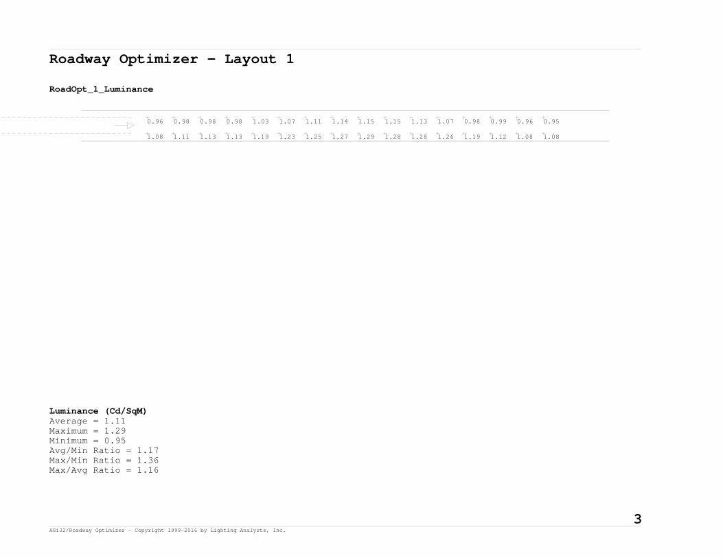
Roadway Optimizer - Layout 1
RoadOpt_1_Luminance
1.08 1.11 1.13 1.13 1.19 1.23 1.25 1.27 1.29 1.28 1.28 1.26 1.19 1.12 1.08 1.08
0.96 0.98 0.98 0.98 1.03 1.07 1.11 1.14 1.15 1.15 1.13 1.07 0.98 0.99 0.96 0.95
Luminance (Cd/SqM)Average = 1.11Maximum = 1.29Minimum = 0.95Avg/Min Ratio = 1.17Max/Min Ratio = 1.36Max/Avg Ratio = 1.16
3 AGi32/Roadway Optimizer - Copyright 1999-2016 by Lighting Analysts, Inc.

Roadway Optimizer - Layout 1
RoadOpt_1_Illum
1.86 1.65 1.33 1.04 0.81 0.65 0.55 0.50 0.50 0.55 0.65 0.81 1.04 1.33 1.65 1.86
1.67 1.53 1.27 1.02 0.85 0.71 0.62 0.57 0.57 0.62 0.71 0.85 1.02 1.27 1.53 1.67
Illuminance (Fc)Average = 1.04Maximum = 1.86Minimum = 0.50Avg/Min Ratio = 2.08Max/Min Ratio = 3.72Max/Avg Ratio = 1.79
4 AGi32/Roadway Optimizer - Copyright 1999-2016 by Lighting Analysts, Inc.

Roadway Optimizer - Layout 1
RoadOpt_1_Vis_Level
-2.54 0.57 1.59 1.75 1.20 0.46 -0.36 -1.23 -1.91 -2.38 -2.76 -3.11 -3.43 -3.74 -4.17 -4.63
-1.96 0.92 2.08 2.31 2.02 1.44 0.74 0.12 -0.51 -0.94 -1.50 -1.87 -2.21 -2.79 -3.38 -3.88
Visibility LevelSTV = 1.863473
5 AGi32/Roadway Optimizer - Copyright 1999-2016 by Lighting Analysts, Inc.

Roadway Optimizer - Layout 1
RoadOpt_1_Vis_Level_Bkgd_Lum
1.13 1.17 1.22 1.25 1.27 1.28 1.28 1.28 1.26 1.20 1.14 1.09 1.07 1.08 1.10 1.13
0.98 1.02 1.06 1.11 1.13 1.15 1.15 1.14 1.09 1.00 0.99 0.96 0.94 0.96 0.97 0.98
Background Luminance (Cd/SqM)Average = 1.11Maximum = 1.28Minimum = 0.94Avg/Min Ratio = 1.18Max/Min Ratio = 1.36Max/Avg Ratio = 1.15
6 AGi32/Roadway Optimizer - Copyright 1999-2016 by Lighting Analysts, Inc.

Roadway Optimizer - Layout 1
RoadOpt_1_Vis_Level_Target_Lum
0.65 1.29 1.60 1.66 1.56 1.39 1.20 1.03 0.90 0.78 0.68 0.59 0.50 0.43 0.34 0.27
0.64 1.22 1.53 1.62 1.60 1.49 1.33 1.17 1.02 0.90 0.79 0.69 0.58 0.50 0.40 0.32
Target Luminance (Cd/SqM)Average = 0.96Maximum = 1.66Minimum = 0.27Avg/Min Ratio = 3.56Max/Min Ratio = 6.15Max/Avg Ratio = 1.73
7 AGi32/Roadway Optimizer - Copyright 1999-2016 by Lighting Analysts, Inc.

Roadway Optimizer - Layout 1
RoadOpt_1_Veil_Lum
0.10 0.09 0.08 0.09 0.11 0.12 0.13 0.15 0.15 0.15 0.15 0.14 0.14 0.13 0.12 0.11
0.10 0.08 0.08 0.09 0.11 0.13 0.15 0.16 0.17 0.17 0.16 0.15 0.15 0.14 0.12 0.11
Veiling Luminance (Cd/SqM)Average = 0.13Maximum = 0.17Minimum = 0.08Avg/Min Ratio = 1.63Max/Min Ratio = 2.13Max/Avg Ratio = 1.31MaxLv Ratio = 0.15Threshold Increment (TI) = 10.16
8 AGi32/Roadway Optimizer - Copyright 1999-2016 by Lighting Analysts, Inc.

Roadway Optimizer - Layout 2
General:
2-LANE RAMP (SLIP OR DIAMOND)
Roadway Standard: IES RP-8-2000R-Table: R3 (Slightly Specular), Q0=0.07 Actual QO Value: 0.07
Roadway Layout:
Layout Type: One Row, Near Side; 1RNS Roadway Width: 24 ftLanes In Direction Of Travel: 2Driver's Side Of Roadway: Right
Luminaire Information:
RFL-215W96LED4K-T-R2M (15' MA)Description: RFL-215W96LED4K-T-R2MFile Name: RFL-215W96LED4K-T-R2M (S1410224m).iesLumens Per Lamp: N.A.Number Of Lamps: 1Total Lamp Lumens: N.A.Luminaire Lumens: 24084Luminaire Watts: 207Efficiency (%): N.A.Total Light Loss Factor: 0.755Luminaire Arrangement: SINGLEArm Length: 15 ftOffset: 0 ft
Luminaire Location Summary:Coordinates in ft
Spacing - Row 1: 220
Label X-Coord Y-Coord Z-Coord Orient Tilt SpinRFL-215W96LED4K-T-R... -440 -16 50 90 0 0RFL-215W96LED4K-T-R... -220 -16 50 90 0 0RFL-215W96LED4K-T-R... 0 -16 50 90 0 0RFL-215W96LED4K-T-R... 220 -16 50 90 0 0RFL-215W96LED4K-T-R... 440 -16 50 90 0 0RFL-215W96LED4K-T-R... 660 -16 50 90 0 0RFL-215W96LED4K-T-R... 880 -16 50 90 0 0
9 AGi32/Roadway Optimizer - Copyright 1999-2016 by Lighting Analysts, Inc.

Roadway Optimizer - Layout 2 - Cont.
Luminaire Location Summary:Coordinates in ft
Total Number of locations: 7
10 AGi32/Roadway Optimizer - Copyright 1999-2016 by Lighting Analysts, Inc.

Roadway Optimizer - Layout 2
RoadOpt_1_Luminance
1.08 1.11 1.13 1.13 1.18 1.22 1.25 1.28 1.29 1.29 1.28 1.25 1.20 1.13 1.09 1.09
1.02 1.05 1.06 1.06 1.11 1.14 1.18 1.21 1.23 1.22 1.21 1.16 1.08 1.04 1.01 1.02
0.88 0.89 0.89 0.91 0.97 1.01 1.04 1.05 1.05 1.06 1.06 0.98 0.91 0.92 0.89 0.87
0.75 0.78 0.81 0.81 0.85 0.86 0.86 0.87 0.90 0.90 0.89 0.83 0.78 0.78 0.74 0.74
Luminance (Cd/SqM)Average = 1.02Maximum = 1.29Minimum = 0.74Avg/Min Ratio = 1.38Max/Min Ratio = 1.74Max/Avg Ratio = 1.26
11 AGi32/Roadway Optimizer - Copyright 1999-2016 by Lighting Analysts, Inc.

Roadway Optimizer - Layout 2
RoadOpt_1_Illum
1.86 1.65 1.33 1.03 0.80 0.64 0.54 0.49 0.49 0.54 0.64 0.80 1.03 1.33 1.65 1.86
1.75 1.58 1.30 1.04 0.85 0.70 0.60 0.55 0.55 0.60 0.70 0.85 1.04 1.30 1.58 1.75
1.59 1.48 1.23 1.01 0.85 0.72 0.64 0.59 0.59 0.64 0.72 0.85 1.01 1.23 1.48 1.59
1.41 1.33 1.15 0.97 0.83 0.72 0.66 0.62 0.62 0.66 0.72 0.83 0.97 1.15 1.33 1.41
Illuminance (Fc)Average = 1.02Maximum = 1.86Minimum = 0.49Avg/Min Ratio = 2.08Max/Min Ratio = 3.8Max/Avg Ratio = 1.82
12 AGi32/Roadway Optimizer - Copyright 1999-2016 by Lighting Analysts, Inc.

Roadway Optimizer - Layout 2
RoadOpt_1_Vis_Level
-2.55 0.59 1.63 1.76 1.15 0.40 -0.46 -1.34 -2.03 -2.50 -2.87 -3.20 -3.52 -3.83 -4.24 -4.68
-2.26 0.72 1.83 2.06 1.69 1.03 0.32 -0.44 -1.14 -1.60 -2.04 -2.40 -2.77 -3.20 -3.73 -4.23
-1.66 1.12 2.26 2.56 2.30 1.80 1.19 0.56 0.15 -0.28 -0.92 -1.27 -1.70 -2.30 -2.96 -3.45
-1.21 1.27 2.52 3.00 2.94 2.50 2.08 1.54 1.05 0.72 0.26 -0.02 -0.63 -1.30 -2.12 -2.78
Visibility LevelSTV = 1.748546
13 AGi32/Roadway Optimizer - Copyright 1999-2016 by Lighting Analysts, Inc.

Roadway Optimizer - Layout 2
RoadOpt_1_Vis_Level_Bkgd_Lum
1.12 1.16 1.21 1.24 1.27 1.29 1.29 1.28 1.26 1.21 1.15 1.10 1.07 1.09 1.10 1.13
1.05 1.10 1.13 1.17 1.20 1.22 1.22 1.21 1.17 1.10 1.05 1.01 1.00 1.02 1.04 1.06
0.90 0.95 1.00 1.04 1.05 1.06 1.05 1.06 1.00 0.92 0.92 0.90 0.87 0.88 0.89 0.89
0.80 0.84 0.86 0.86 0.86 0.90 0.90 0.89 0.85 0.79 0.78 0.75 0.74 0.75 0.78 0.80
Background Luminance (Cd/SqM)Average = 1.02Maximum = 1.29Minimum = 0.74Avg/Min Ratio = 1.38Max/Min Ratio = 1.74Max/Avg Ratio = 1.26
14 AGi32/Roadway Optimizer - Copyright 1999-2016 by Lighting Analysts, Inc.

Roadway Optimizer - Layout 2
RoadOpt_1_Vis_Level_Target_Lum
0.65 1.29 1.61 1.66 1.54 1.36 1.18 1.01 0.87 0.76 0.66 0.57 0.49 0.42 0.33 0.27
0.65 1.26 1.57 1.65 1.61 1.47 1.29 1.12 0.98 0.86 0.75 0.65 0.55 0.47 0.38 0.30
0.63 1.19 1.48 1.59 1.58 1.49 1.36 1.20 1.06 0.94 0.83 0.72 0.61 0.53 0.42 0.33
0.60 1.09 1.39 1.51 1.53 1.47 1.37 1.25 1.12 1.01 0.90 0.78 0.67 0.57 0.45 0.36
Target Luminance (Cd/SqM)Average = 0.97Maximum = 1.66Minimum = 0.27Avg/Min Ratio = 3.59Max/Min Ratio = 6.15Max/Avg Ratio = 1.71
15 AGi32/Roadway Optimizer - Copyright 1999-2016 by Lighting Analysts, Inc.

Roadway Optimizer - Layout 2
RoadOpt_1_Veil_Lum
0.10 0.09 0.08 0.09 0.10 0.12 0.13 0.15 0.15 0.15 0.14 0.14 0.13 0.13 0.12 0.11
0.10 0.09 0.09 0.09 0.11 0.13 0.14 0.16 0.16 0.16 0.16 0.15 0.14 0.14 0.13 0.11
0.09 0.08 0.08 0.09 0.11 0.13 0.15 0.16 0.17 0.17 0.16 0.15 0.15 0.13 0.12 0.11
0.08 0.07 0.08 0.09 0.11 0.13 0.15 0.16 0.17 0.17 0.16 0.15 0.14 0.13 0.11 0.10
Veiling Luminance (Cd/SqM)Average = 0.13Maximum = 0.17Minimum = 0.07Avg/Min Ratio = 1.63Max/Min Ratio = 2.13Max/Avg Ratio = 1.31MaxLv Ratio = 0.17Threshold Increment (TI) = 10.88
16 AGi32/Roadway Optimizer - Copyright 1999-2016 by Lighting Analysts, Inc.

Roadway Optimizer - Layout 3
General:
3-LANE MAINLINE (MEDIAN MOUNTED)
Roadway Standard: IES RP-8-2000R-Table: R3 (Slightly Specular), Q0=0.07 Actual QO Value: 0.07
Roadway Layout:
Layout Type: One Row, Median Mounted; 1R_MM Roadway Width: 39 ftMedian Width: 35 ftLanes In Direction Of Travel: 3Driver's Side Of Roadway: Right
Luminaire Information:
RFL-215W96LED4K-T-R2M (2-6' MA)Description: RFL-215W96LED4K-T-R2MFile Name: RFL-215W96LED4K-T-R2M (S1410224m).iesLumens Per Lamp: N.A.Number Of Lamps: 1Total Lamp Lumens: N.A.Luminaire Lumens: 24084Luminaire Watts: 207Efficiency (%): N.A.Total Light Loss Factor: 0.755Luminaire Arrangement: BACK-BACKArm Length: 6 ftOffset: 0 ftArrangement Lamp Lumens: N.A.Arrangement Luminaire Lumens: 48168Arrangement Watts: 414
Luminaire Location Summary:Coordinates in ft
Spacing - Row 1: 220
Label X-Coord Y-Coord Z-Coord Orient Tilt SpinRFL-215W96LED4K-T-R... 880 56.5 50 270 0 0RFL-215W96LED4K-T-R... 660 56.5 50 270 0 0RFL-215W96LED4K-T-R... 440 56.5 50 270 0 0
17 AGi32/Roadway Optimizer - Copyright 1999-2016 by Lighting Analysts, Inc.

Roadway Optimizer - Layout 3 - Cont.
Luminaire Location Summary:Coordinates in ft
RFL-215W96LED4K-T-R... 220 56.5 50 270 0 0RFL-215W96LED4K-T-R... 0 56.5 50 270 0 0RFL-215W96LED4K-T-R... -220 56.5 50 270 0 0RFL-215W96LED4K-T-R... -440 56.5 50 270 0 0
Total Number of locations: 7
18 AGi32/Roadway Optimizer - Copyright 1999-2016 by Lighting Analysts, Inc.

Roadway Optimizer - Layout 3
RoadOpt_1_Luminance
0.42 0.43 0.45 0.45 0.48 0.48 0.49 0.51 0.50 0.50 0.48 0.45 0.41 0.39 0.38 0.40
0.51 0.52 0.54 0.54 0.56 0.55 0.58 0.58 0.58 0.56 0.56 0.53 0.50 0.48 0.48 0.49
0.62 0.62 0.62 0.63 0.66 0.66 0.67 0.68 0.68 0.66 0.66 0.64 0.61 0.58 0.60 0.61
0.75 0.76 0.77 0.75 0.76 0.77 0.81 0.81 0.81 0.80 0.79 0.76 0.74 0.73 0.73 0.73
0.88 0.90 0.91 0.91 0.96 0.97 0.97 0.97 1.00 1.00 0.99 0.93 0.89 0.90 0.87 0.87
1.10 1.11 1.10 1.09 1.14 1.19 1.23 1.25 1.25 1.25 1.24 1.17 1.10 1.12 1.10 1.09
Luminance (Cd/SqM)Average = 0.75Maximum = 1.25Minimum = 0.38Avg/Min Ratio = 1.97Max/Min Ratio = 3.29Max/Avg Ratio = 1.67
19 AGi32/Roadway Optimizer - Copyright 1999-2016 by Lighting Analysts, Inc.

Roadway Optimizer - Layout 3
RoadOpt_1_Illum
0.82 0.79 0.76 0.73 0.69 0.65 0.62 0.59 0.59 0.62 0.65 0.69 0.73 0.76 0.79 0.82
1.02 0.97 0.91 0.84 0.77 0.70 0.65 0.63 0.63 0.65 0.70 0.77 0.84 0.91 0.97 1.02
1.24 1.16 1.05 0.93 0.83 0.74 0.69 0.66 0.66 0.69 0.74 0.83 0.93 1.05 1.16 1.24
1.45 1.36 1.19 1.01 0.88 0.78 0.71 0.68 0.68 0.71 0.78 0.88 1.01 1.19 1.36 1.45
1.69 1.56 1.32 1.09 0.94 0.81 0.73 0.69 0.69 0.73 0.81 0.94 1.09 1.32 1.56 1.69
2.00 1.81 1.49 1.22 1.01 0.86 0.76 0.71 0.71 0.76 0.86 1.01 1.22 1.49 1.81 2.00
Illuminance (Fc)Average = 0.96Maximum = 2.00Minimum = 0.59Avg/Min Ratio = 1.63Max/Min Ratio = 3.39Max/Avg Ratio = 2.08
20 AGi32/Roadway Optimizer - Copyright 1999-2016 by Lighting Analysts, Inc.

Roadway Optimizer - Layout 3
RoadOpt_1_Vis_Level
0.47 1.82 2.96 3.84 4.19 4.32 4.15 3.82 3.62 3.54 3.34 2.99 2.49 1.73 0.88 0.10
0.19 1.88 3.18 3.98 4.21 4.23 3.87 3.53 3.23 3.07 2.75 2.33 1.75 1.10 0.24 -0.63
-0.17 1.86 3.27 3.97 4.00 3.79 3.53 3.08 2.66 2.45 2.09 1.54 0.93 0.41 -0.54 -1.44
-0.70 1.78 3.18 3.70 3.67 3.38 2.90 2.43 1.99 1.68 1.20 0.78 0.23 -0.42 -1.49 -2.28
-1.13 1.55 2.83 3.22 3.12 2.64 2.16 1.65 1.13 0.78 0.31 -0.01 -0.70 -1.45 -2.27 -2.93
-1.65 1.33 2.56 2.84 2.54 1.97 1.31 0.64 0.20 -0.20 -0.90 -1.34 -1.81 -2.47 -3.20 -3.75
Visibility LevelSTV = 1.994771
21 AGi32/Roadway Optimizer - Copyright 1999-2016 by Lighting Analysts, Inc.

Roadway Optimizer - Layout 3
RoadOpt_1_Vis_Level_Bkgd_Lum
0.45 0.47 0.48 0.49 0.51 0.51 0.50 0.48 0.46 0.42 0.40 0.38 0.40 0.42 0.43 0.44
0.54 0.55 0.55 0.58 0.58 0.58 0.57 0.56 0.54 0.51 0.48 0.47 0.48 0.51 0.52 0.53
0.63 0.65 0.66 0.67 0.67 0.69 0.65 0.65 0.65 0.62 0.58 0.60 0.61 0.62 0.62 0.62
0.75 0.75 0.76 0.80 0.81 0.81 0.80 0.79 0.78 0.74 0.73 0.72 0.73 0.74 0.76 0.77
0.90 0.95 0.96 0.97 0.96 1.00 1.00 0.99 0.95 0.90 0.90 0.87 0.87 0.88 0.90 0.90
1.08 1.13 1.17 1.23 1.25 1.26 1.25 1.25 1.20 1.11 1.11 1.10 1.08 1.09 1.11 1.10
Background Luminance (Cd/SqM)Average = 0.75Maximum = 1.26Minimum = 0.38Avg/Min Ratio = 1.97Max/Min Ratio = 3.32Max/Avg Ratio = 1.68
22 AGi32/Roadway Optimizer - Copyright 1999-2016 by Lighting Analysts, Inc.

Roadway Optimizer - Layout 3
RoadOpt_1_Vis_Level_Target_Lum
0.51 0.74 0.94 1.10 1.20 1.24 1.22 1.17 1.11 1.06 0.99 0.89 0.79 0.67 0.54 0.44
0.56 0.87 1.10 1.28 1.35 1.35 1.31 1.24 1.18 1.11 1.02 0.92 0.80 0.68 0.54 0.44
0.60 1.00 1.27 1.42 1.47 1.45 1.39 1.31 1.22 1.14 1.04 0.92 0.79 0.68 0.54 0.43
0.65 1.13 1.44 1.57 1.59 1.55 1.46 1.36 1.25 1.15 1.03 0.91 0.78 0.67 0.53 0.42
0.71 1.29 1.61 1.71 1.72 1.65 1.53 1.40 1.27 1.14 1.02 0.90 0.76 0.65 0.52 0.42
0.79 1.46 1.81 1.92 1.90 1.78 1.62 1.44 1.28 1.14 1.01 0.88 0.76 0.65 0.52 0.42
Target Luminance (Cd/SqM)Average = 1.06Maximum = 1.92Minimum = 0.42Avg/Min Ratio = 2.52Max/Min Ratio = 4.57Max/Avg Ratio = 1.81
23 AGi32/Roadway Optimizer - Copyright 1999-2016 by Lighting Analysts, Inc.

Roadway Optimizer - Layout 3
RoadOpt_1_Veil_Lum
0.05 0.05 0.05 0.06 0.08 0.09 0.10 0.11 0.12 0.11 0.10 0.09 0.08 0.07 0.07 0.06
0.06 0.06 0.06 0.07 0.09 0.11 0.12 0.13 0.14 0.13 0.13 0.11 0.10 0.09 0.08 0.07
0.07 0.06 0.07 0.08 0.10 0.12 0.14 0.15 0.16 0.15 0.15 0.13 0.12 0.11 0.09 0.08
0.08 0.08 0.08 0.09 0.11 0.14 0.15 0.17 0.17 0.17 0.16 0.15 0.14 0.13 0.11 0.10
0.10 0.09 0.09 0.10 0.13 0.15 0.16 0.18 0.19 0.19 0.18 0.17 0.16 0.14 0.13 0.11
0.11 0.10 0.11 0.12 0.14 0.16 0.18 0.20 0.20 0.20 0.19 0.18 0.17 0.16 0.15 0.13
Veiling Luminance (Cd/SqM)Average = 0.12Maximum = 0.20Minimum = 0.05Avg/Min Ratio = 2.4Max/Min Ratio = 4Max/Avg Ratio = 1.67MaxLv Ratio = 0.27Threshold Increment (TI) = 16.36
24 AGi32/Roadway Optimizer - Copyright 1999-2016 by Lighting Analysts, Inc.

Roadway Optimizer - Layout 4
General:
4-LANE MAINLINE (MEDIAN MOUNTED)
Roadway Standard: IES RP-8-2000R-Table: R3 (Slightly Specular), Q0=0.07 Actual QO Value: 0.07
Roadway Layout:
Layout Type: One Row, Median Mounted; 1R_MM Roadway Width: 51 ftMedian Width: 35 ftLanes In Direction Of Travel: 4Driver's Side Of Roadway: Right
Luminaire Information:
RFL-215W96LED4K-T-R2M (2-6' MA)Description: RFL-215W96LED4K-T-R2MFile Name: RFL-215W96LED4K-T-R2M (S1410224m).iesLumens Per Lamp: N.A.Number Of Lamps: 1Total Lamp Lumens: N.A.Luminaire Lumens: 24084Luminaire Watts: 207Efficiency (%): N.A.Total Light Loss Factor: 0.755Luminaire Arrangement: BACK-BACKArm Length: 6 ftOffset: 0 ftArrangement Lamp Lumens: N.A.Arrangement Luminaire Lumens: 48168Arrangement Watts: 414
Luminaire Location Summary:Coordinates in ft
Spacing - Row 1: 190
Label X-Coord Y-Coord Z-Coord Orient Tilt SpinRFL-215W96LED4K-T-R... -380 68.5 50 270 0 0RFL-215W96LED4K-T-R... -190 68.5 50 270 0 0RFL-215W96LED4K-T-R... 0 68.5 50 270 0 0
25 AGi32/Roadway Optimizer - Copyright 1999-2016 by Lighting Analysts, Inc.

Roadway Optimizer - Layout 4 - Cont.
Luminaire Location Summary:Coordinates in ft
RFL-215W96LED4K-T-R... 190 68.5 50 270 0 0RFL-215W96LED4K-T-R... 380 68.5 50 270 0 0RFL-215W96LED4K-T-R... 570 68.5 50 270 0 0RFL-215W96LED4K-T-R... 760 68.5 50 270 0 0RFL-215W96LED4K-T-R... 950 68.5 50 270 0 0
Total Number of locations: 8
26 AGi32/Roadway Optimizer - Copyright 1999-2016 by Lighting Analysts, Inc.

Roadway Optimizer - Layout 4
RoadOpt_1_Luminance
0.35 0.36 0.39 0.40 0.41 0.41 0.41 0.39 0.37 0.36 0.34 0.34
0.43 0.44 0.47 0.48 0.49 0.49 0.48 0.46 0.44 0.43 0.41 0.41
0.52 0.52 0.56 0.57 0.56 0.56 0.55 0.54 0.52 0.50 0.50 0.51
0.65 0.64 0.64 0.67 0.65 0.64 0.62 0.63 0.62 0.59 0.59 0.61
0.76 0.77 0.77 0.77 0.76 0.75 0.73 0.75 0.74 0.72 0.73 0.73
0.92 0.92 0.88 0.91 0.90 0.88 0.88 0.91 0.88 0.88 0.88 0.89
1.10 1.13 1.10 1.10 1.07 1.09 1.10 1.11 1.06 1.07 1.06 1.04
1.33 1.34 1.32 1.37 1.38 1.36 1.37 1.39 1.31 1.33 1.33 1.28
Luminance (Cd/SqM)Average = 0.76Maximum = 1.39Minimum = 0.34Avg/Min Ratio = 2.24Max/Min Ratio = 4.09Max/Avg Ratio = 1.83
27 AGi32/Roadway Optimizer - Copyright 1999-2016 by Lighting Analysts, Inc.

Roadway Optimizer - Layout 4
RoadOpt_1_Illum
0.58 0.58 0.59 0.60 0.60 0.59 0.59 0.60 0.60 0.59 0.58 0.58
0.74 0.73 0.73 0.71 0.69 0.67 0.67 0.69 0.71 0.73 0.73 0.74
0.93 0.89 0.86 0.82 0.76 0.73 0.73 0.76 0.82 0.86 0.89 0.93
1.13 1.07 0.99 0.91 0.83 0.78 0.78 0.83 0.91 0.99 1.07 1.13
1.34 1.24 1.12 0.98 0.88 0.82 0.82 0.88 0.98 1.12 1.24 1.34
1.54 1.42 1.22 1.05 0.92 0.86 0.86 0.92 1.05 1.22 1.42 1.54
1.78 1.61 1.33 1.12 0.97 0.90 0.90 0.97 1.12 1.33 1.61 1.78
2.07 1.83 1.48 1.21 1.03 0.94 0.94 1.03 1.21 1.48 1.83 2.07
Illuminance (Fc)Average = 1Maximum = 2.07Minimum = 0.58Avg/Min Ratio = 1.72Max/Min Ratio = 3.57Max/Avg Ratio = 2.07
28 AGi32/Roadway Optimizer - Copyright 1999-2016 by Lighting Analysts, Inc.

Roadway Optimizer - Layout 4
RoadOpt_1_Vis_Level
1.75 2.47 3.02 3.55 4.02 4.16 4.18 4.09 3.94 3.52 2.92 2.10
1.54 2.47 3.30 3.87 4.19 4.15 4.02 3.80 3.59 3.18 2.46 1.65
1.20 2.56 3.51 4.14 4.25 4.04 3.74 3.41 3.10 2.63 1.90 1.10
0.84 2.47 3.72 4.13 4.09 3.68 3.33 2.96 2.47 2.01 1.19 0.51
0.48 2.39 3.57 3.93 3.73 3.19 2.78 2.28 1.79 1.27 0.46 -0.23
0.03 2.11 3.31 3.49 3.17 2.64 2.11 1.50 1.05 0.42 -0.38 -1.17
-0.71 1.75 2.79 2.92 2.53 1.93 1.36 0.65 0.27 -0.44 -1.42 -2.19
-1.38 1.35 2.32 2.27 1.73 1.11 0.44 -0.37 -0.90 -1.72 -2.50 -3.10
Visibility LevelSTV = 2.227703
29 AGi32/Roadway Optimizer - Copyright 1999-2016 by Lighting Analysts, Inc.

Roadway Optimizer - Layout 4
RoadOpt_1_Vis_Level_Bkgd_Lum
0.40 0.40 0.41 0.41 0.40 0.38 0.36 0.35 0.33 0.34 0.36 0.37
0.47 0.49 0.48 0.49 0.47 0.45 0.43 0.42 0.41 0.41 0.44 0.45
0.56 0.57 0.56 0.55 0.54 0.53 0.51 0.50 0.50 0.51 0.52 0.54
0.64 0.67 0.64 0.63 0.63 0.63 0.61 0.59 0.60 0.63 0.65 0.64
0.77 0.76 0.76 0.73 0.73 0.75 0.74 0.72 0.73 0.74 0.77 0.77
0.89 0.91 0.90 0.88 0.88 0.90 0.88 0.88 0.88 0.90 0.93 0.90
1.09 1.09 1.09 1.09 1.11 1.09 1.05 1.08 1.05 1.07 1.11 1.12
1.33 1.38 1.38 1.36 1.39 1.36 1.30 1.34 1.30 1.31 1.33 1.33
Background Luminance (Cd/SqM)Average = 0.76Maximum = 1.39Minimum = 0.33Avg/Min Ratio = 2.3Max/Min Ratio = 4.21Max/Avg Ratio = 1.83
30 AGi32/Roadway Optimizer - Copyright 1999-2016 by Lighting Analysts, Inc.

Roadway Optimizer - Layout 4
RoadOpt_1_Vis_Level_Target_Lum
0.63 0.74 0.85 0.94 1.02 1.03 1.02 0.98 0.92 0.86 0.76 0.65
0.69 0.87 1.02 1.13 1.18 1.17 1.13 1.06 1.00 0.93 0.81 0.69
0.75 1.00 1.19 1.32 1.33 1.28 1.21 1.14 1.06 0.98 0.84 0.72
0.81 1.14 1.37 1.47 1.45 1.36 1.28 1.19 1.10 1.00 0.85 0.73
0.87 1.28 1.53 1.59 1.54 1.44 1.34 1.23 1.13 1.01 0.85 0.72
0.91 1.42 1.67 1.72 1.65 1.52 1.39 1.26 1.13 0.99 0.84 0.70
0.97 1.58 1.83 1.87 1.76 1.60 1.44 1.27 1.13 0.98 0.83 0.68
1.05 1.76 2.04 2.04 1.91 1.69 1.47 1.29 1.12 0.96 0.81 0.68
Target Luminance (Cd/SqM)Average = 1.16Maximum = 2.04Minimum = 0.63Avg/Min Ratio = 1.84Max/Min Ratio = 3.24Max/Avg Ratio = 1.76
31 AGi32/Roadway Optimizer - Copyright 1999-2016 by Lighting Analysts, Inc.

Roadway Optimizer - Layout 4
RoadOpt_1_Veil_Lum
0.05 0.05 0.05 0.06 0.07 0.07 0.08 0.08 0.08 0.07 0.07 0.06
0.07 0.06 0.06 0.07 0.08 0.09 0.10 0.10 0.10 0.09 0.08 0.07
0.08 0.07 0.08 0.08 0.10 0.11 0.12 0.12 0.12 0.11 0.10 0.09
0.09 0.09 0.09 0.10 0.11 0.12 0.14 0.14 0.14 0.13 0.12 0.10
0.11 0.10 0.10 0.11 0.13 0.14 0.15 0.16 0.16 0.15 0.14 0.12
0.13 0.12 0.12 0.12 0.14 0.15 0.17 0.18 0.18 0.17 0.16 0.14
0.15 0.14 0.14 0.14 0.15 0.16 0.19 0.19 0.20 0.19 0.18 0.16
0.17 0.16 0.16 0.16 0.17 0.18 0.20 0.20 0.21 0.20 0.19 0.18
Veiling Luminance (Cd/SqM)Average = 0.12Maximum = 0.21Minimum = 0.05Avg/Min Ratio = 2.4Max/Min Ratio = 4.2Max/Avg Ratio = 1.75MaxLv Ratio = 0.28Threshold Increment (TI) = 17.00
32 AGi32/Roadway Optimizer - Copyright 1999-2016 by Lighting Analysts, Inc.

Roadway Optimizer - Layout 5
General:
3-LANE MAINLINE W/LANE 0 (OUTSIDE MOUNTED)
Roadway Standard: IES RP-8-2000R-Table: R3 (Slightly Specular), Q0=0.07 Actual QO Value: 0.07
Roadway Layout:
Layout Type: One Row, Near Side; 1RNS Roadway Width: 53 ftLanes In Direction Of Travel: 4Driver's Side Of Roadway: Right
Luminaire Information:
RFL-215W96LED4K-T-R2M (15' MA)Description: RFL-215W96LED4K-T-R2MFile Name: RFL-215W96LED4K-T-R2M (S1410224m).iesLumens Per Lamp: N.A.Number Of Lamps: 1Total Lamp Lumens: N.A.Luminaire Lumens: 24084Luminaire Watts: 207Efficiency (%): N.A.Total Light Loss Factor: 0.755Luminaire Arrangement: SINGLEArm Length: 15 ftOffset: 0 ft
Luminaire Location Summary:Coordinates in ft
Spacing - Row 1: 185
Label X-Coord Y-Coord Z-Coord Orient Tilt SpinRFL-215W96LED4K-T-R... -370 -17 50 90 0 0RFL-215W96LED4K-T-R... -185 -17 50 90 0 0RFL-215W96LED4K-T-R... 0 -17 50 90 0 0RFL-215W96LED4K-T-R... 185 -17 50 90 0 0RFL-215W96LED4K-T-R... 370 -17 50 90 0 0RFL-215W96LED4K-T-R... 555 -17 50 90 0 0RFL-215W96LED4K-T-R... 740 -17 50 90 0 0
33 AGi32/Roadway Optimizer - Copyright 1999-2016 by Lighting Analysts, Inc.

Roadway Optimizer - Layout 5 - Cont.
Luminaire Location Summary:Coordinates in ft
RFL-215W96LED4K-T-R... 925 -17 50 90 0 0
Total Number of locations: 8
34 AGi32/Roadway Optimizer - Copyright 1999-2016 by Lighting Analysts, Inc.

Roadway Optimizer - Layout 5
RoadOpt_1_Luminance
1.38 1.40 1.42 1.41 1.41 1.41 1.41 1.41 1.43 1.45 1.44 1.42 1.38 1.35 1.36
1.23 1.26 1.25 1.25 1.28 1.30 1.30 1.30 1.31 1.31 1.27 1.25 1.25 1.22 1.21
1.05 1.09 1.09 1.09 1.10 1.09 1.07 1.09 1.12 1.10 1.06 1.05 1.05 1.00 1.01
0.90 0.92 0.91 0.88 0.90 0.91 0.91 0.89 0.91 0.92 0.88 0.89 0.89 0.87 0.87
0.74 0.76 0.77 0.77 0.78 0.77 0.77 0.74 0.75 0.78 0.75 0.75 0.73 0.73 0.73
0.64 0.65 0.65 0.65 0.68 0.67 0.64 0.63 0.63 0.64 0.64 0.61 0.58 0.60 0.62
0.52 0.51 0.54 0.56 0.58 0.57 0.57 0.55 0.55 0.54 0.52 0.50 0.50 0.50 0.51
0.42 0.43 0.45 0.46 0.49 0.50 0.49 0.48 0.48 0.46 0.44 0.43 0.41 0.40 0.40
Luminance (Cd/SqM)Average = 0.88Maximum = 1.45Minimum = 0.40Avg/Min Ratio = 2.2Max/Min Ratio = 3.63Max/Avg Ratio = 1.65
35 AGi32/Roadway Optimizer - Copyright 1999-2016 by Lighting Analysts, Inc.

Roadway Optimizer - Layout 5
RoadOpt_1_Illum
1.93 1.76 1.48 1.22 1.01 0.85 0.75 0.72 0.75 0.85 1.01 1.22 1.48 1.76 1.93
1.79 1.67 1.44 1.21 1.03 0.90 0.82 0.79 0.82 0.90 1.03 1.21 1.44 1.67 1.79
1.61 1.52 1.35 1.16 1.02 0.91 0.85 0.83 0.85 0.91 1.02 1.16 1.35 1.52 1.61
1.41 1.36 1.25 1.10 0.99 0.90 0.85 0.83 0.85 0.90 0.99 1.10 1.25 1.36 1.41
1.24 1.20 1.12 1.03 0.95 0.87 0.83 0.81 0.83 0.87 0.95 1.03 1.12 1.20 1.24
1.07 1.04 0.99 0.94 0.89 0.83 0.79 0.78 0.79 0.83 0.89 0.94 0.99 1.04 1.07
0.88 0.86 0.85 0.83 0.81 0.77 0.74 0.73 0.74 0.77 0.81 0.83 0.85 0.86 0.88
0.70 0.69 0.70 0.71 0.70 0.69 0.68 0.67 0.68 0.69 0.70 0.71 0.70 0.69 0.70
Illuminance (Fc)Average = 1.03Maximum = 1.93Minimum = 0.67Avg/Min Ratio = 1.54Max/Min Ratio = 2.88Max/Avg Ratio = 1.87
36 AGi32/Roadway Optimizer - Copyright 1999-2016 by Lighting Analysts, Inc.
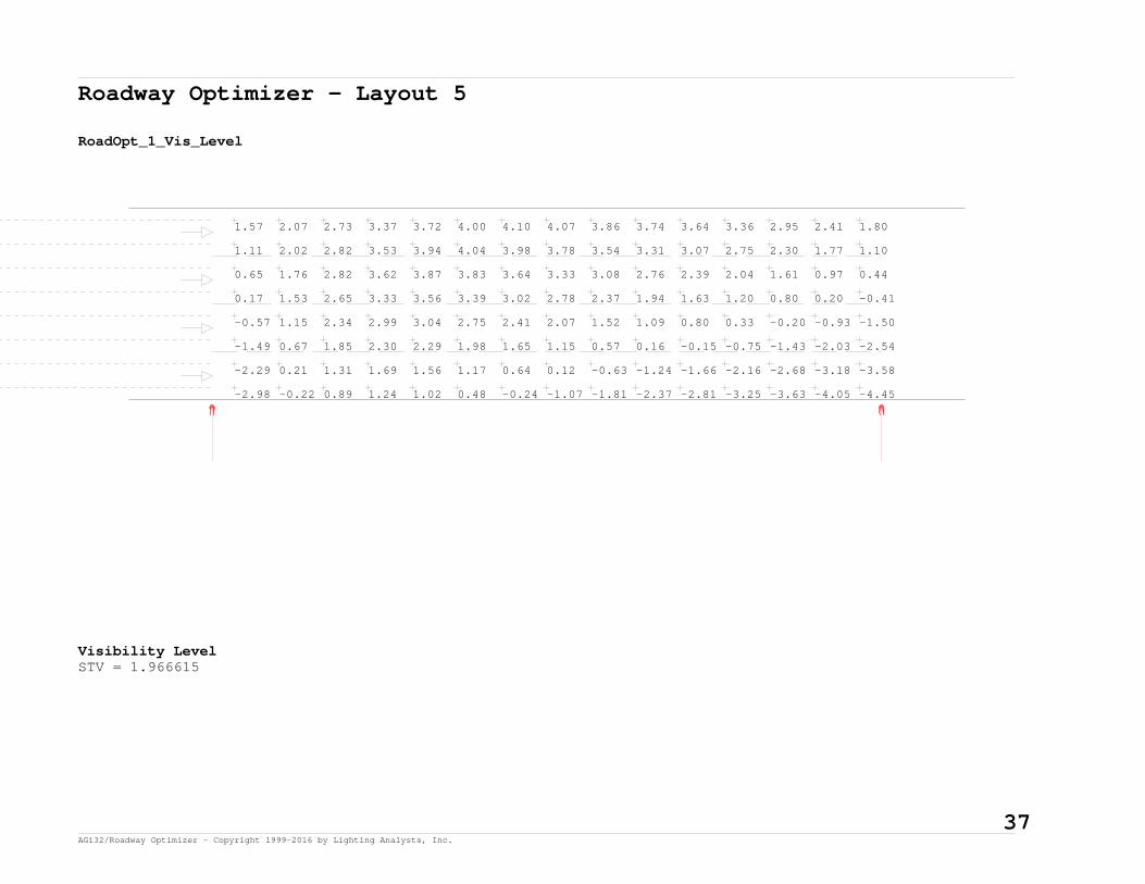
Roadway Optimizer - Layout 5
RoadOpt_1_Vis_Level
-2.98 -0.22 0.89 1.24 1.02 0.48 -0.24 -1.07 -1.81 -2.37 -2.81 -3.25 -3.63 -4.05 -4.45
-2.29 0.21 1.31 1.69 1.56 1.17 0.64 0.12 -0.63 -1.24 -1.66 -2.16 -2.68 -3.18 -3.58
-1.49 0.67 1.85 2.30 2.29 1.98 1.65 1.15 0.57 0.16 -0.15 -0.75 -1.43 -2.03 -2.54
-0.57 1.15 2.34 2.99 3.04 2.75 2.41 2.07 1.52 1.09 0.80 0.33 -0.20 -0.93 -1.50
0.17 1.53 2.65 3.33 3.56 3.39 3.02 2.78 2.37 1.94 1.63 1.20 0.80 0.20 -0.41
0.65 1.76 2.82 3.62 3.87 3.83 3.64 3.33 3.08 2.76 2.39 2.04 1.61 0.97 0.44
1.11 2.02 2.82 3.53 3.94 4.04 3.98 3.78 3.54 3.31 3.07 2.75 2.30 1.77 1.10
1.57 2.07 2.73 3.37 3.72 4.00 4.10 4.07 3.86 3.74 3.64 3.36 2.95 2.41 1.80
Visibility LevelSTV = 1.966615
37 AGi32/Roadway Optimizer - Copyright 1999-2016 by Lighting Analysts, Inc.

Roadway Optimizer - Layout 5
RoadOpt_1_Vis_Level_Bkgd_Lum
1.41 1.41 1.41 1.41 1.41 1.43 1.45 1.44 1.42 1.38 1.35 1.36 1.38 1.41 1.42
1.26 1.29 1.30 1.30 1.30 1.31 1.30 1.26 1.26 1.24 1.21 1.22 1.23 1.26 1.25
1.09 1.10 1.09 1.07 1.10 1.12 1.09 1.05 1.06 1.04 1.00 1.02 1.05 1.10 1.08
0.88 0.90 0.92 0.90 0.90 0.92 0.91 0.88 0.89 0.88 0.87 0.88 0.90 0.92 0.90
0.78 0.78 0.77 0.76 0.74 0.76 0.77 0.75 0.74 0.73 0.73 0.73 0.74 0.77 0.77
0.66 0.68 0.67 0.64 0.63 0.63 0.64 0.63 0.60 0.59 0.60 0.62 0.64 0.65 0.64
0.56 0.58 0.57 0.56 0.55 0.54 0.53 0.52 0.50 0.50 0.50 0.51 0.52 0.52 0.55
0.46 0.50 0.49 0.49 0.48 0.47 0.46 0.44 0.43 0.41 0.40 0.41 0.42 0.43 0.45
Background Luminance (Cd/SqM)Average = 0.88Maximum = 1.45Minimum = 0.40Avg/Min Ratio = 2.2Max/Min Ratio = 3.63Max/Avg Ratio = 1.65
38 AGi32/Roadway Optimizer - Copyright 1999-2016 by Lighting Analysts, Inc.
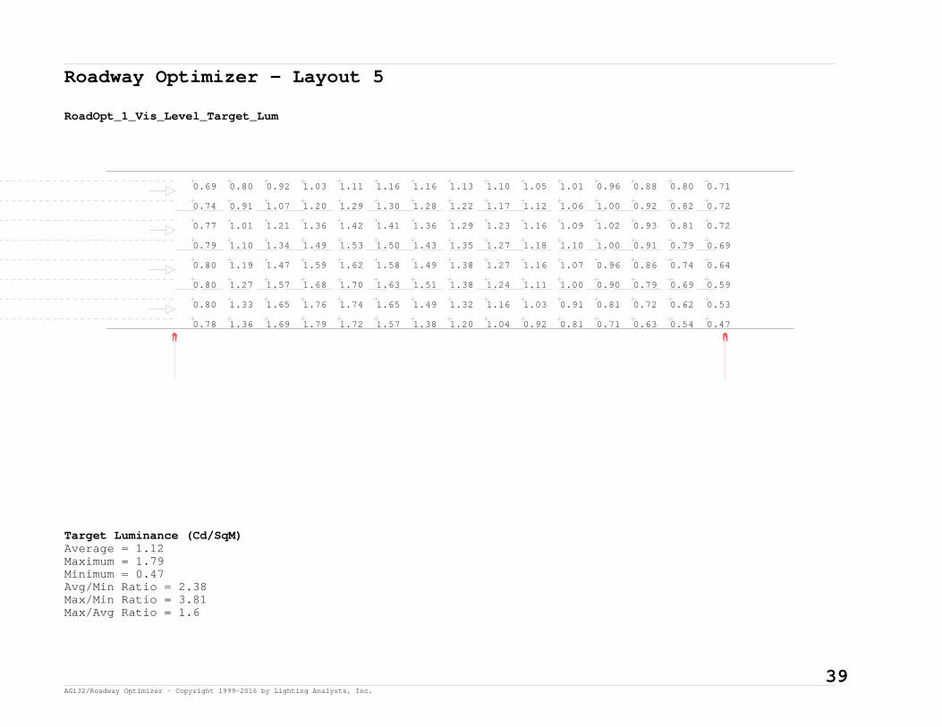
Roadway Optimizer - Layout 5
RoadOpt_1_Vis_Level_Target_Lum
0.78 1.36 1.69 1.79 1.72 1.57 1.38 1.20 1.04 0.92 0.81 0.71 0.63 0.54 0.47
0.80 1.33 1.65 1.76 1.74 1.65 1.49 1.32 1.16 1.03 0.91 0.81 0.72 0.62 0.53
0.80 1.27 1.57 1.68 1.70 1.63 1.51 1.38 1.24 1.11 1.00 0.90 0.79 0.69 0.59
0.80 1.19 1.47 1.59 1.62 1.58 1.49 1.38 1.27 1.16 1.07 0.96 0.86 0.74 0.64
0.79 1.10 1.34 1.49 1.53 1.50 1.43 1.35 1.27 1.18 1.10 1.00 0.91 0.79 0.69
0.77 1.01 1.21 1.36 1.42 1.41 1.36 1.29 1.23 1.16 1.09 1.02 0.93 0.81 0.72
0.74 0.91 1.07 1.20 1.29 1.30 1.28 1.22 1.17 1.12 1.06 1.00 0.92 0.82 0.72
0.69 0.80 0.92 1.03 1.11 1.16 1.16 1.13 1.10 1.05 1.01 0.96 0.88 0.80 0.71
Target Luminance (Cd/SqM)Average = 1.12Maximum = 1.79Minimum = 0.47Avg/Min Ratio = 2.38Max/Min Ratio = 3.81Max/Avg Ratio = 1.6
39 AGi32/Roadway Optimizer - Copyright 1999-2016 by Lighting Analysts, Inc.

Roadway Optimizer - Layout 5
RoadOpt_1_Veil_Lum
0.15 0.14 0.14 0.14 0.13 0.14 0.13 0.14 0.15 0.15 0.16 0.16 0.16 0.15 0.15
0.15 0.14 0.14 0.14 0.14 0.15 0.14 0.15 0.16 0.17 0.17 0.17 0.17 0.16 0.16
0.14 0.13 0.13 0.13 0.13 0.14 0.14 0.15 0.17 0.17 0.18 0.17 0.17 0.16 0.15
0.13 0.12 0.12 0.12 0.12 0.13 0.14 0.15 0.16 0.17 0.17 0.17 0.16 0.15 0.14
0.11 0.10 0.10 0.10 0.11 0.12 0.13 0.14 0.15 0.16 0.16 0.15 0.15 0.14 0.12
0.10 0.09 0.09 0.09 0.10 0.11 0.12 0.12 0.14 0.14 0.14 0.14 0.13 0.12 0.11
0.08 0.08 0.08 0.08 0.08 0.09 0.10 0.11 0.12 0.12 0.12 0.12 0.11 0.10 0.09
0.07 0.06 0.06 0.07 0.07 0.08 0.09 0.09 0.10 0.10 0.10 0.10 0.09 0.08 0.08
Veiling Luminance (Cd/SqM)Average = 0.13Maximum = 0.18Minimum = 0.06Avg/Min Ratio = 2.17Max/Min Ratio = 3Max/Avg Ratio = 1.38MaxLv Ratio = 0.20Threshold Increment (TI) = 12.96
40 AGi32/Roadway Optimizer - Copyright 1999-2016 by Lighting Analysts, Inc.

Photometric Calculation Examples (Loop Ramps)

Page Intentionally Blank

ILLINOIS TOLLWAY TYPICAL LOOP RAMP LIGHTING CACLULATIONS
MANUFACTURER: {ENTER}PRODUCT LINE: {ENTER}PRODUCT NUMBER(S): {ENTER}CALCULATED BY: {ENTER}DATE: {ENTER}
1 AGi32 - Copyright 1999-2016 by Lighting Analysts, Inc. 1/15/2016 Job File: Tollway Typical Roadway Lighting Calculation Template.AGICalculations based on published IES Methods and recommendations, values rounded for display purposes.Results derived from content of manufacturers photometric file.
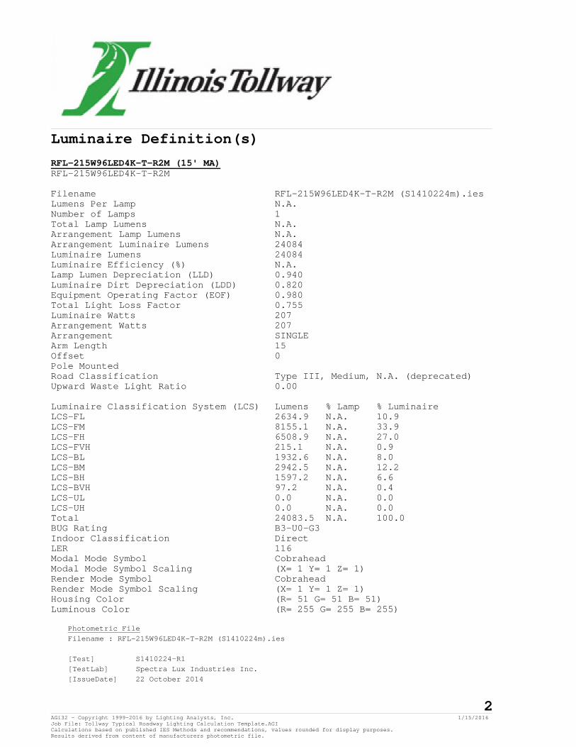
Luminaire Definition(s)
RFL-215W96LED4K-T-R2M (15' MA)RFL-215W96LED4K-T-R2M
Filename RFL-215W96LED4K-T-R2M (S1410224m).iesLumens Per Lamp N.A.Number of Lamps 1Total Lamp Lumens N.A.Arrangement Lamp Lumens N.A.Arrangement Luminaire Lumens 24084Luminaire Lumens 24084Luminaire Efficiency (%) N.A.Lamp Lumen Depreciation (LLD) 0.940Luminaire Dirt Depreciation (LDD) 0.820Equipment Operating Factor (EOF) 0.980Total Light Loss Factor 0.755Luminaire Watts 207Arrangement Watts 207Arrangement SINGLEArm Length 15Offset 0Pole MountedRoad Classification Type III, Medium, N.A. (deprecated)Upward Waste Light Ratio 0.00
Luminaire Classification System (LCS) Lumens % Lamp % LuminaireLCS-FL 2634.9 N.A. 10.9LCS-FM 8155.1 N.A. 33.9LCS-FH 6508.9 N.A. 27.0LCS-FVH 215.1 N.A. 0.9LCS-BL 1932.6 N.A. 8.0LCS-BM 2942.5 N.A. 12.2LCS-BH 1597.2 N.A. 6.6LCS-BVH 97.2 N.A. 0.4LCS-UL 0.0 N.A. 0.0LCS-UH 0.0 N.A. 0.0Total 24083.5 N.A. 100.0BUG Rating B3-U0-G3Indoor Classification DirectLER 116Modal Mode Symbol CobraheadModal Mode Symbol Scaling (X= 1 Y= 1 Z= 1)Render Mode Symbol CobraheadRender Mode Symbol Scaling (X= 1 Y= 1 Z= 1)Housing Color (R= 51 G= 51 B= 51)Luminous Color (R= 255 G= 255 B= 255)
Photometric FileFilename : RFL-215W96LED4K-T-R2M (S1410224m).ies
[Test] S1410224-R1[TestLab] Spectra Lux Industries Inc.[IssueDate] 22 October 2014
2 AGi32 - Copyright 1999-2016 by Lighting Analysts, Inc. 1/15/2016 Job File: Tollway Typical Roadway Lighting Calculation Template.AGICalculations based on published IES Methods and recommendations, values rounded for display purposes.Results derived from content of manufacturers photometric file.
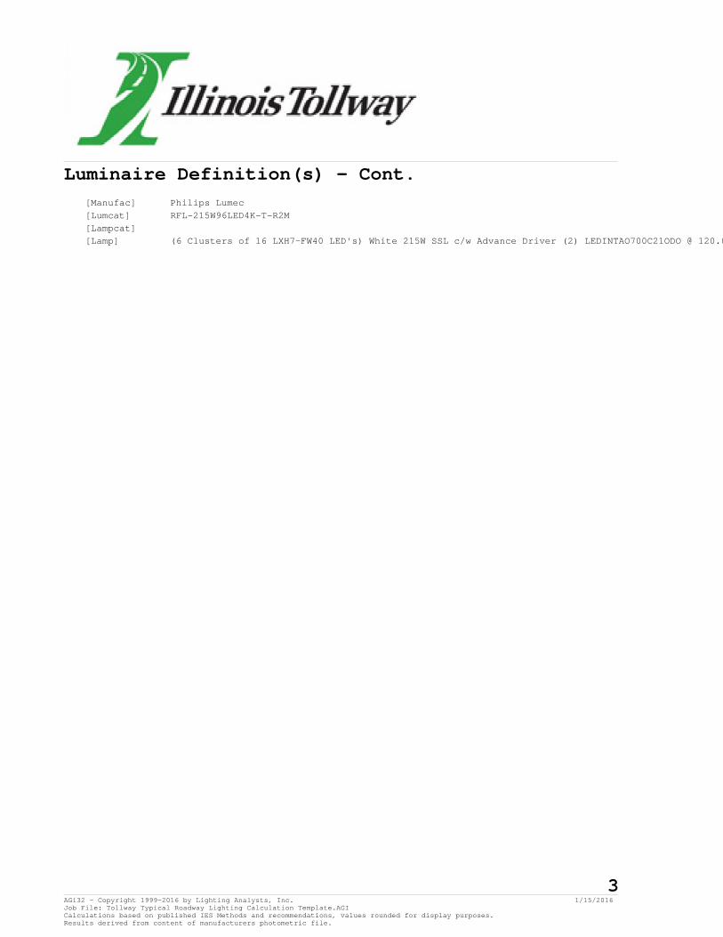
Luminaire Definition(s) - Cont.[Manufac] Philips Lumec[Lumcat] RFL-215W96LED4K-T-R2M[Lampcat] [Lamp] (6 Clusters of 16 LXH7-FW40 LED's) White 215W SSL c/w Advance Driver (2) LEDINTAO700C21ODO @ 120.0
3 AGi32 - Copyright 1999-2016 by Lighting Analysts, Inc. 1/15/2016 Job File: Tollway Typical Roadway Lighting Calculation Template.AGICalculations based on published IES Methods and recommendations, values rounded for display purposes.Results derived from content of manufacturers photometric file.

Calculation Summary
150' RADIUS LOOP RAMP Project: Project_1PolygonCoordinates in Feet
Point Spacing L-R 6Point Spacing T-B 10Grid Orient 0Grid Tilt 0Meter Type Horizontal
Illuminance (Fc)Average 1.16Maximum 1.75Minimum 0.55Avg/Min 2.11Max/Min 3.18
175' RADIUS LOOP RAMP Project: Project_1PolygonCoordinates in Feet
Point Spacing L-R 6Point Spacing T-B 10Grid Orient 0Grid Tilt 0Meter Type Horizontal
Illuminance (Fc)Average 1.09Maximum 1.86Minimum 0.46Avg/Min 2.37Max/Min 4.04
200' RADIUS LOOP RAMP Project: Project_1PolygonCoordinates in Feet
Point Spacing L-R 6Point Spacing T-B 10Grid Orient 0Grid Tilt 0Meter Type Horizontal
4 AGi32 - Copyright 1999-2016 by Lighting Analysts, Inc. 1/15/2016 Job File: Tollway Typical Roadway Lighting Calculation Template.AGICalculations based on published IES Methods and recommendations, values rounded for display purposes.Results derived from content of manufacturers photometric file.

Calculation Summary - Cont.
Illuminance (Fc)Average 1.03Maximum 1.82Minimum 0.34Avg/Min 3.03Max/Min 5.35
300' RADIUS LOOP RAMP Project: Project_1PolygonCoordinates in Feet
Point Spacing L-R 6Point Spacing T-B 10Grid Orient 0Grid Tilt 0Meter Type Horizontal
Illuminance (Fc)Average 1.01Maximum 1.82Minimum 0.37Avg/Min 2.73Max/Min 4.92
400' RADIUS LOOP RAMP Project: Project_1PolygonCoordinates in Feet
Point Spacing L-R 6Point Spacing T-B 10Grid Orient 0Grid Tilt 0Meter Type Horizontal
Illuminance (Fc)Average 1.06Maximum 1.80Minimum 0.48Avg/Min 2.21Max/Min 3.75
500' RADIUS LOOP RAMP Project: Project_1Polygon
5 AGi32 - Copyright 1999-2016 by Lighting Analysts, Inc. 1/15/2016 Job File: Tollway Typical Roadway Lighting Calculation Template.AGICalculations based on published IES Methods and recommendations, values rounded for display purposes.Results derived from content of manufacturers photometric file.

Calculation Summary - Cont.
Coordinates in Feet
Point Spacing L-R 6Point Spacing T-B 10Grid Orient 0Grid Tilt 0Meter Type Horizontal
Illuminance (Fc)Average 1.10Maximum 1.83Minimum 0.54Avg/Min 2.04Max/Min 3.39
6 AGi32 - Copyright 1999-2016 by Lighting Analysts, Inc. 1/15/2016 Job File: Tollway Typical Roadway Lighting Calculation Template.AGICalculations based on published IES Methods and recommendations, values rounded for display purposes.Results derived from content of manufacturers photometric file.

TOLLWAY TYPICAL LOOP RAMP LIGHTING CALCULATIONSMANUFACTURER: {ENTER}PRODUCT LINE: {ENTER}PRODUCT NUMBER(S): {ENTER}CALCULATED BY: {ENTER}DATE: {DD\DD\YYYY}
150' RADIUS150' SPACINGIES FILE: {ENTER}
165' SPACINGIES FILE: {ENTER}
175' RADIUS 200' RADIUS180' SPACINGIES FILE: {ENTER} 300' RADIUS
190' SPACINGIES FILE: {ENTER} 400' RADIUS
190' SPACINGIES FILE: {ENTER}
IES FILE: {ENTER}
500' RADIUS190' SPACING
Luminaire ScheduleSymbol Label Arrangement
Calculation SummaryLabel
LLF Filename Arm IES Class Long. Class Lum. Lumens Lum. Watts
CalcType Units Avg Max Min Avg/Min Max/Min150' RADIUS LOOP RAMP Illuminance Fc 1.16 1.75 0.55 2.11 3.18
RFL-215W96LED4K-T-R2SINGLE 0.755 RFL-215W96LED4K-T-R2M (S14102215 Type III Medium 24084 207
175' RADIUS LOOP RAMP Illuminance Fc 1.09 1.86 0.46 2.37 4.04200' RADIUS LOOP RAMP Illuminance Fc 1.03 1.82
500' RADIUS LOOP RAMP Illuminance Fc 1.10 1.83 0.54 2.04 3.39
0.34 3.03 5.35300' RADIUS LOOP RAMP Illuminance Fc 1.01 1.82 0.37 2.73 4.92400' RADIUS LOOP RAMP Illuminance Fc 1.06 1.80 0.48 2.21 3.75


Photometric Calculation Examples (Underpass)

Page Intentionally Blank

Roadway Optimizer - Layout 1
General:
1-LANE UNDERPASS (1-SIDE)
Roadway Standard: IES RP-8-2000R-Table: R3 (Slightly Specular), Q0=0.07 Actual QO Value: 0.07
Roadway Layout:
Layout Type: One Row, Near Side; 1RNS Roadway Width: 16 ftLanes In Direction Of Travel: 1Driver's Side Of Roadway: Right
Luminaire Information:
LTS-5N-100L40K-DVDescription: LTS-5N-100L40K-DVFile Name: LTS-5N-100L40K-DV.iesLumens Per Lamp: N.A.Number Of Lamps: 96Total Lamp Lumens: N.A.Luminaire Lumens: 11340Luminaire Watts: 105.52Efficiency (%): N.A.Total Light Loss Factor: 0.750Luminaire Arrangement: SINGLEArm Length: 0 ftOffset: 0 ft
Luminaire Location Summary:Coordinates in ft
Spacing - Row 1: 60
Label X-Coord Y-Coord Z-Coord Orient Tilt SpinLTS-5N-100L40K-DV 300 -11 16 90 30 0LTS-5N-100L40K-DV 240 -11 16 90 30 0LTS-5N-100L40K-DV 180 -11 16 90 30 0LTS-5N-100L40K-DV 120 -11 16 90 30 0LTS-5N-100L40K-DV 60 -11 16 90 30 0LTS-5N-100L40K-DV 0 -11 16 90 30 0LTS-5N-100L40K-DV -60 -11 16 90 30 0
1 AGi32/Roadway Optimizer - Copyright 1999-2016 by Lighting Analysts, Inc.

Roadway Optimizer - Layout 1 - Cont.
Luminaire Location Summary:Coordinates in ft
LTS-5N-100L40K-DV -120 -11 16 90 30 0LTS-5N-100L40K-DV -180 -11 16 90 30 0LTS-5N-100L40K-DV -240 -11 16 90 30 0LTS-5N-100L40K-DV -300 -11 16 90 30 0
Total Number of locations: 11
2 AGi32/Roadway Optimizer - Copyright 1999-2016 by Lighting Analysts, Inc.

Roadway Optimizer - Layout 1
RoadOpt_1_Luminance
1.43 1.21 0.98 0.81 0.77 0.83 0.97 1.13 1.35 1.46
0.80 0.76 0.65 0.57 0.56 0.58 0.61 0.69 0.79 0.80
Luminance (Cd/SqM)Average = 0.89Maximum = 1.46Minimum = 0.56Avg/Min Ratio = 1.59Max/Min Ratio = 2.61Max/Avg Ratio = 1.64
3 AGi32/Roadway Optimizer - Copyright 1999-2016 by Lighting Analysts, Inc.

Roadway Optimizer - Layout 1
RoadOpt_1_Illum
4.28 3.40 2.27 1.48 1.11 1.11 1.48 2.27 3.40 4.28
2.02 1.75 1.37 1.06 0.90 0.90 1.06 1.37 1.75 2.02
Illuminance (Fc)Average = 1.96Maximum = 4.28Minimum = 0.90Avg/Min Ratio = 2.18Max/Min Ratio = 4.76Max/Avg Ratio = 2.18
4 AGi32/Roadway Optimizer - Copyright 1999-2016 by Lighting Analysts, Inc.

Roadway Optimizer - Layout 1
RoadOpt_1_Vis_Level
1.52 8.06 8.97 6.85 4.58 2.25 0.32 -1.47 -3.30 -4.47
1.10 5.34 7.22 7.06 5.47 3.68 2.03 0.49 -1.00 -2.09
Visibility LevelSTV = 3.139427
5 AGi32/Roadway Optimizer - Copyright 1999-2016 by Lighting Analysts, Inc.

Roadway Optimizer - Layout 1
RoadOpt_1_Vis_Level_Bkgd_Lum
1.02 1.23 1.39 1.49 1.32 1.10 0.90 0.76 0.79 0.88
0.64 0.74 0.78 0.80 0.79 0.72 0.60 0.56 0.57 0.58
Background Luminance (Cd/SqM)Average = 0.88Maximum = 1.49Minimum = 0.56Avg/Min Ratio = 1.57Max/Min Ratio = 2.66Max/Avg Ratio = 1.69
6 AGi32/Roadway Optimizer - Copyright 1999-2016 by Lighting Analysts, Inc.

Roadway Optimizer - Layout 1
RoadOpt_1_Vis_Level_Target_Lum
1.65 3.48 3.66 3.00 2.20 1.50 1.01 0.71 0.49 0.35
0.94 1.87 2.19 2.08 1.73 1.35 0.98 0.72 0.54 0.41
Target Luminance (Cd/SqM)Average = 1.54Maximum = 3.66Minimum = 0.35Avg/Min Ratio = 4.4Max/Min Ratio = 10.46Max/Avg Ratio = 2.38
7 AGi32/Roadway Optimizer - Copyright 1999-2016 by Lighting Analysts, Inc.

Roadway Optimizer - Layout 1
RoadOpt_1_Veil_Lum
0.12 0.14 0.14 0.12 0.09 0.06 0.07 0.08 0.09 0.11
0.07 0.08 0.07 0.06 0.05 0.04 0.05 0.05 0.06 0.07
Veiling Luminance (Cd/SqM)Average = 0.08Maximum = 0.14Minimum = 0.04Avg/Min Ratio = 2Max/Min Ratio = 3.5Max/Avg Ratio = 1.75MaxLv Ratio = 0.16Threshold Increment (TI) = 9.99
8 AGi32/Roadway Optimizer - Copyright 1999-2016 by Lighting Analysts, Inc.

Roadway Optimizer - Layout 2
General:
2-LANE UNDERPASS (1-SIDE)
Roadway Standard: IES RP-8-2000R-Table: R3 (Slightly Specular), Q0=0.07 Actual QO Value: 0.07
Roadway Layout:
Layout Type: One Row, Near Side; 1RNS Roadway Width: 24 ftLanes In Direction Of Travel: 2Driver's Side Of Roadway: Right
Luminaire Information:
LTS-5N-100L40K-DVDescription: LTS-5N-100L40K-DVFile Name: LTS-5N-100L40K-DV.iesLumens Per Lamp: N.A.Number Of Lamps: 96Total Lamp Lumens: N.A.Luminaire Lumens: 11340Luminaire Watts: 105.52Efficiency (%): N.A.Total Light Loss Factor: 0.750Luminaire Arrangement: SINGLEArm Length: 0 ftOffset: 0 ft
Luminaire Location Summary:Coordinates in ft
Spacing - Row 1: 60
Label X-Coord Y-Coord Z-Coord Orient Tilt SpinLTS-5N-100L40K-DV -300 -11 16 90 30 0LTS-5N-100L40K-DV -240 -11 16 90 30 0LTS-5N-100L40K-DV -180 -11 16 90 30 0LTS-5N-100L40K-DV -120 -11 16 90 30 0LTS-5N-100L40K-DV -60 -11 16 90 30 0LTS-5N-100L40K-DV 0 -11 16 90 30 0LTS-5N-100L40K-DV 60 -11 16 90 30 0
9 AGi32/Roadway Optimizer - Copyright 1999-2016 by Lighting Analysts, Inc.

Roadway Optimizer - Layout 2 - Cont.
Luminaire Location Summary:Coordinates in ft
LTS-5N-100L40K-DV 120 -11 16 90 30 0LTS-5N-100L40K-DV 180 -11 16 90 30 0LTS-5N-100L40K-DV 240 -11 16 90 30 0LTS-5N-100L40K-DV 300 -11 16 90 30 0
Total Number of locations: 11
10 AGi32/Roadway Optimizer - Copyright 1999-2016 by Lighting Analysts, Inc.

Roadway Optimizer - Layout 2
RoadOpt_1_Luminance
1.59 1.29 1.02 0.84 0.80 0.88 1.04 1.23 1.47 1.63
0.93 0.88 0.77 0.65 0.63 0.67 0.72 0.85 0.93 0.93
0.67 0.63 0.56 0.50 0.50 0.48 0.52 0.57 0.63 0.67
0.46 0.45 0.43 0.39 0.37 0.36 0.38 0.42 0.43 0.46
Luminance (Cd/SqM)Average = 0.74Maximum = 1.63Minimum = 0.36Avg/Min Ratio = 2.06Max/Min Ratio = 4.53Max/Avg Ratio = 2.2
11 AGi32/Roadway Optimizer - Copyright 1999-2016 by Lighting Analysts, Inc.

Roadway Optimizer - Layout 2
RoadOpt_1_Illum
4.70 3.68 2.39 1.52 1.13 1.13 1.52 2.39 3.68 4.70
2.67 2.23 1.66 1.22 0.99 0.99 1.22 1.66 2.23 2.67
1.57 1.39 1.13 0.92 0.81 0.81 0.92 1.13 1.39 1.57
0.98 0.90 0.79 0.69 0.63 0.63 0.69 0.79 0.90 0.98
Illuminance (Fc)Average = 1.6Maximum = 4.70Minimum = 0.63Avg/Min Ratio = 2.54Max/Min Ratio = 7.46Max/Avg Ratio = 2.94
12 AGi32/Roadway Optimizer - Copyright 1999-2016 by Lighting Analysts, Inc.

Roadway Optimizer - Layout 2
RoadOpt_1_Vis_Level
1.45 8.36 8.88 6.56 4.19 1.97 0.07 -1.85 -3.65 -4.85
1.32 6.20 8.14 7.51 5.46 3.29 1.41 -0.10 -1.75 -2.80
1.07 4.77 6.56 6.53 5.41 4.10 2.53 0.99 -0.12 -1.32
1.27 3.93 5.51 5.87 5.35 4.45 3.19 1.88 0.88 0.08
Visibility LevelSTV = 2.978142
13 AGi32/Roadway Optimizer - Copyright 1999-2016 by Lighting Analysts, Inc.

Roadway Optimizer - Layout 2
RoadOpt_1_Vis_Level_Bkgd_Lum
1.12 1.33 1.56 1.65 1.47 1.17 0.94 0.80 0.82 0.92
0.76 0.91 0.93 0.93 0.91 0.84 0.71 0.63 0.65 0.68
0.54 0.60 0.65 0.67 0.66 0.61 0.52 0.50 0.49 0.50
0.40 0.42 0.44 0.46 0.46 0.44 0.41 0.38 0.36 0.36
Background Luminance (Cd/SqM)Average = 0.74Maximum = 1.65Minimum = 0.36Avg/Min Ratio = 2.06Max/Min Ratio = 4.58Max/Avg Ratio = 2.23
14 AGi32/Roadway Optimizer - Copyright 1999-2016 by Lighting Analysts, Inc.

Roadway Optimizer - Layout 2
RoadOpt_1_Vis_Level_Target_Lum
1.78 3.75 3.87 3.11 2.24 1.50 1.01 0.70 0.48 0.33
1.14 2.33 2.68 2.42 1.92 1.43 1.00 0.72 0.53 0.39
0.80 1.51 1.81 1.77 1.55 1.25 0.95 0.70 0.54 0.42
0.62 1.04 1.28 1.31 1.20 1.05 0.86 0.67 0.52 0.42
Target Luminance (Cd/SqM)Average = 1.34Maximum = 3.87Minimum = 0.33Avg/Min Ratio = 4.06Max/Min Ratio = 11.73Max/Avg Ratio = 2.89
15 AGi32/Roadway Optimizer - Copyright 1999-2016 by Lighting Analysts, Inc.

Roadway Optimizer - Layout 2
RoadOpt_1_Veil_Lum
0.13 0.15 0.16 0.14 0.10 0.06 0.07 0.08 0.10 0.11
0.09 0.10 0.09 0.08 0.06 0.05 0.05 0.06 0.07 0.08
0.06 0.06 0.06 0.05 0.04 0.04 0.04 0.05 0.05 0.06
0.04 0.04 0.04 0.04 0.03 0.03 0.03 0.04 0.04 0.04
Veiling Luminance (Cd/SqM)Average = 0.07Maximum = 0.16Minimum = 0.03Avg/Min Ratio = 2.33Max/Min Ratio = 5.33Max/Avg Ratio = 2.29MaxLv Ratio = 0.22Threshold Increment (TI) = 13.23
16 AGi32/Roadway Optimizer - Copyright 1999-2016 by Lighting Analysts, Inc.

Roadway Optimizer - Layout 3
General:
3-LANE UNDERPASS (OPPOSITE)
Roadway Standard: IES RP-8-2000R-Table: R3 (Slightly Specular), Q0=0.07 Actual QO Value: 0.07
Roadway Layout:
Layout Type: Two Rows, Opposite; 2R_OPP Roadway Width: 39 ftLanes In Direction Of Travel: 3Driver's Side Of Roadway: Right
Luminaire Information:
LTS-5N-100L40K-DVDescription: LTS-5N-100L40K-DVFile Name: LTS-5N-100L40K-DV.iesLumens Per Lamp: N.A.Number Of Lamps: 96Total Lamp Lumens: N.A.Luminaire Lumens: 11340Luminaire Watts: 105.52Efficiency (%): N.A.Total Light Loss Factor: 0.750Luminaire Arrangement: SINGLEArm Length: 0 ftOffset: 0 ft
Luminaire Location Summary:Coordinates in ft
Spacing - Row 1: 60Spacing - Row 2: 60
Label X-Coord Y-Coord Z-Coord Orient Tilt SpinLTS-5N-100L40K-DV 240 -15 16 90 30 0LTS-5N-100L40K-DV -240 -15 16 90 30 0LTS-5N-100L40K-DV -180 -15 16 90 30 0LTS-5N-100L40K-DV -120 -15 16 90 30 0LTS-5N-100L40K-DV -60 -15 16 90 30 0LTS-5N-100L40K-DV 0 -15 16 90 30 0
17 AGi32/Roadway Optimizer - Copyright 1999-2016 by Lighting Analysts, Inc.

Roadway Optimizer - Layout 3 - Cont.
Luminaire Location Summary:Coordinates in ft
LTS-5N-100L40K-DV 60 -15 16 90 30 0LTS-5N-100L40K-DV 120 -15 16 90 30 0LTS-5N-100L40K-DV 180 -15 16 90 30 0LTS-5N-100L40K-DV 300 -15 16 90 30 0LTS-5N-100L40K-DV -300 -15 16 90 30 0LTS-5N-100L40K-DV -300 51 16 270 30 0LTS-5N-100L40K-DV -240 51 16 270 30 0LTS-5N-100L40K-DV -180 51 16 270 30 0LTS-5N-100L40K-DV -120 51 16 270 30 0LTS-5N-100L40K-DV -60 51 16 270 30 0LTS-5N-100L40K-DV 0 51 16 270 30 0LTS-5N-100L40K-DV 60 51 16 270 30 0LTS-5N-100L40K-DV 120 51 16 270 30 0LTS-5N-100L40K-DV 180 51 16 270 30 0LTS-5N-100L40K-DV 240 51 16 270 30 0LTS-5N-100L40K-DV 300 51 16 270 30 0
Total Number of locations: 22
18 AGi32/Roadway Optimizer - Copyright 1999-2016 by Lighting Analysts, Inc.

Roadway Optimizer - Layout 3
RoadOpt_1_Luminance
1.31 1.17 1.03 0.90 0.87 0.91 1.00 1.15 1.22 1.31
1.03 0.99 0.88 0.78 0.77 0.78 0.81 0.89 0.98 1.02
0.90 0.87 0.82 0.75 0.71 0.69 0.73 0.79 0.83 0.88
0.95 0.91 0.83 0.76 0.74 0.71 0.76 0.81 0.87 0.93
1.12 1.07 0.93 0.83 0.81 0.84 0.88 1.00 1.11 1.12
1.59 1.38 1.14 0.98 0.93 0.99 1.13 1.30 1.51 1.62
Luminance (Cd/SqM)Average = 0.97Maximum = 1.62Minimum = 0.69Avg/Min Ratio = 1.41Max/Min Ratio = 2.35Max/Avg Ratio = 1.67
19 AGi32/Roadway Optimizer - Copyright 1999-2016 by Lighting Analysts, Inc.

Roadway Optimizer - Layout 3
RoadOpt_1_Illum
3.53 2.94 2.22 1.65 1.37 1.37 1.65 2.22 2.94 3.53
2.27 2.04 1.70 1.43 1.28 1.28 1.43 1.70 2.04 2.27
1.84 1.70 1.50 1.33 1.22 1.22 1.33 1.50 1.70 1.84
1.97 1.80 1.56 1.36 1.24 1.24 1.36 1.56 1.80 1.97
2.72 2.38 1.90 1.52 1.32 1.32 1.52 1.90 2.38 2.72
4.51 3.65 2.55 1.77 1.40 1.40 1.77 2.55 3.65 4.51
Illuminance (Fc)Average = 1.99Maximum = 4.51Minimum = 1.22Avg/Min Ratio = 1.63Max/Min Ratio = 3.7Max/Avg Ratio = 2.27
20 AGi32/Roadway Optimizer - Copyright 1999-2016 by Lighting Analysts, Inc.
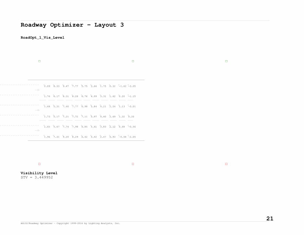
Roadway Optimizer - Layout 3
RoadOpt_1_Vis_Level
1.96 7.31 9.20 8.29 6.42 4.42 2.47 0.93 -0.48 -2.05
1.65 5.67 7.74 7.98 6.85 5.41 3.83 2.12 0.68 -0.56
1.73 5.17 7.21 7.72 7.11 5.97 4.40 2.69 1.32 0.20
1.68 5.31 7.40 7.77 6.98 5.84 4.21 2.54 1.13 -0.01
1.76 6.17 8.31 8.28 6.76 4.99 3.31 1.62 0.20 -1.15
2.09 8.33 9.47 7.77 5.75 3.66 1.75 0.32 -1.62 -3.05
Visibility LevelSTV = 3.449952
21 AGi32/Roadway Optimizer - Copyright 1999-2016 by Lighting Analysts, Inc.

Roadway Optimizer - Layout 3
RoadOpt_1_Vis_Level_Bkgd_Lum
1.04 1.21 1.27 1.32 1.25 1.12 0.97 0.87 0.89 0.95
0.85 0.93 1.00 1.03 1.02 0.94 0.82 0.78 0.78 0.78
0.76 0.81 0.85 0.89 0.89 0.85 0.79 0.73 0.70 0.70
0.78 0.84 0.90 0.94 0.94 0.88 0.80 0.75 0.71 0.73
0.93 1.07 1.10 1.12 1.10 1.02 0.86 0.81 0.82 0.85
1.18 1.39 1.56 1.64 1.49 1.27 1.06 0.93 0.96 1.04
Background Luminance (Cd/SqM)Average = 0.97Maximum = 1.64Minimum = 0.70Avg/Min Ratio = 1.39Max/Min Ratio = 2.34Max/Avg Ratio = 1.69
22 AGi32/Roadway Optimizer - Copyright 1999-2016 by Lighting Analysts, Inc.

Roadway Optimizer - Layout 3
RoadOpt_1_Vis_Level_Target_Lum
1.71 3.20 3.63 3.29 2.69 2.10 1.58 1.24 0.97 0.76
1.33 2.32 2.77 2.76 2.47 2.07 1.65 1.30 1.03 0.81
1.21 1.99 2.43 2.51 2.32 2.03 1.69 1.32 1.04 0.83
1.24 2.09 2.53 2.58 2.37 2.04 1.67 1.32 1.04 0.83
1.46 2.65 3.09 2.98 2.57 2.09 1.62 1.28 1.01 0.79
2.01 3.90 4.18 3.57 2.79 2.08 1.55 1.20 0.92 0.72
Target Luminance (Cd/SqM)Average = 1.95Maximum = 4.18Minimum = 0.72Avg/Min Ratio = 2.71Max/Min Ratio = 5.81Max/Avg Ratio = 2.14
23 AGi32/Roadway Optimizer - Copyright 1999-2016 by Lighting Analysts, Inc.

Roadway Optimizer - Layout 3
RoadOpt_1_Veil_Lum
0.12 0.13 0.13 0.11 0.09 0.07 0.08 0.09 0.10 0.11
0.10 0.09 0.09 0.08 0.07 0.06 0.07 0.08 0.08 0.09
0.08 0.08 0.08 0.07 0.06 0.06 0.07 0.07 0.08 0.08
0.09 0.09 0.08 0.07 0.07 0.06 0.07 0.07 0.08 0.08
0.11 0.11 0.10 0.09 0.08 0.07 0.07 0.08 0.09 0.10
0.14 0.16 0.16 0.14 0.10 0.08 0.09 0.10 0.11 0.13
Veiling Luminance (Cd/SqM)Average = 0.09Maximum = 0.16Minimum = 0.06Avg/Min Ratio = 1.5Max/Min Ratio = 2.67Max/Avg Ratio = 1.78MaxLv Ratio = 0.16Threshold Increment (TI) = 10.66
24 AGi32/Roadway Optimizer - Copyright 1999-2016 by Lighting Analysts, Inc.

Roadway Optimizer - Layout 4
General:
4-LANE UNDERPASS (2-SIDE)
Roadway Standard: IES RP-8-2000R-Table: R3 (Slightly Specular), Q0=0.07 Actual QO Value: 0.07
Roadway Layout:
Layout Type: Two Rows, Opposite; 2R_OPP Roadway Width: 51 ftLanes In Direction Of Travel: 4Driver's Side Of Roadway: Right
Luminaire Information:
LTS-5N-100L40K-DVDescription: LTS-5N-100L40K-DVFile Name: LTS-5N-100L40K-DV.iesLumens Per Lamp: N.A.Number Of Lamps: 96Total Lamp Lumens: N.A.Luminaire Lumens: 11340Luminaire Watts: 105.52Efficiency (%): N.A.Total Light Loss Factor: 0.750Luminaire Arrangement: SINGLEArm Length: 0 ftOffset: 0 ft
Luminaire Location Summary:Coordinates in ft
Spacing - Row 1: 60Spacing - Row 2: 60
Label X-Coord Y-Coord Z-Coord Orient Tilt SpinLTS-5N-100L40K-DV 300 -15 16 90 30 0LTS-5N-100L40K-DV -240 -15 16 90 30 0LTS-5N-100L40K-DV -180 -15 16 90 30 0LTS-5N-100L40K-DV -120 -15 16 90 30 0LTS-5N-100L40K-DV -60 -15 16 90 30 0LTS-5N-100L40K-DV 0 -15 16 90 30 0
25 AGi32/Roadway Optimizer - Copyright 1999-2016 by Lighting Analysts, Inc.

Roadway Optimizer - Layout 4 - Cont.
Luminaire Location Summary:Coordinates in ft
LTS-5N-100L40K-DV 60 -15 16 90 30 0LTS-5N-100L40K-DV 120 -15 16 90 30 0LTS-5N-100L40K-DV 180 -15 16 90 30 0LTS-5N-100L40K-DV -300 -15 16 90 30 0LTS-5N-100L40K-DV 240 -15 16 90 30 0LTS-5N-100L40K-DV 300 63 16 270 30 0LTS-5N-100L40K-DV -240 63 16 270 30 0LTS-5N-100L40K-DV -180 63 16 270 30 0LTS-5N-100L40K-DV -120 63 16 270 30 0LTS-5N-100L40K-DV -60 63 16 270 30 0LTS-5N-100L40K-DV 0 63 16 270 30 0LTS-5N-100L40K-DV 60 63 16 270 30 0LTS-5N-100L40K-DV 120 63 16 270 30 0LTS-5N-100L40K-DV 180 63 16 270 30 0LTS-5N-100L40K-DV 240 63 16 270 30 0LTS-5N-100L40K-DV -300 63 16 270 30 0
Total Number of locations: 22
26 AGi32/Roadway Optimizer - Copyright 1999-2016 by Lighting Analysts, Inc.

Roadway Optimizer - Layout 4
RoadOpt_1_Luminance
1.20 1.07 0.95 0.82 0.80 0.83 0.92 1.05 1.13 1.21
0.90 0.85 0.76 0.69 0.68 0.69 0.72 0.78 0.87 0.90
0.73 0.69 0.65 0.61 0.58 0.57 0.61 0.66 0.68 0.72
0.69 0.68 0.63 0.58 0.55 0.55 0.56 0.59 0.63 0.67
0.70 0.68 0.63 0.58 0.56 0.56 0.57 0.62 0.65 0.68
0.80 0.76 0.68 0.64 0.63 0.60 0.66 0.70 0.75 0.79
1.00 0.95 0.84 0.75 0.73 0.76 0.80 0.91 1.01 1.01
1.49 1.30 1.07 0.91 0.86 0.92 1.06 1.21 1.42 1.51
Luminance (Cd/SqM)Average = 0.8Maximum = 1.51Minimum = 0.55Avg/Min Ratio = 1.45Max/Min Ratio = 2.75Max/Avg Ratio = 1.89
27 AGi32/Roadway Optimizer - Copyright 1999-2016 by Lighting Analysts, Inc.

Roadway Optimizer - Layout 4
RoadOpt_1_Illum
3.39 2.80 2.09 1.52 1.25 1.25 1.52 2.09 2.80 3.39
2.06 1.84 1.52 1.26 1.12 1.12 1.26 1.52 1.84 2.06
1.45 1.35 1.21 1.08 1.01 1.01 1.08 1.21 1.35 1.45
1.23 1.17 1.09 1.01 0.95 0.95 1.01 1.09 1.17 1.23
1.30 1.22 1.12 1.03 0.97 0.97 1.03 1.12 1.22 1.30
1.68 1.53 1.33 1.15 1.06 1.06 1.15 1.33 1.53 1.68
2.56 2.22 1.75 1.38 1.19 1.19 1.38 1.75 2.22 2.56
4.40 3.55 2.44 1.66 1.30 1.30 1.66 2.44 3.55 4.40
Illuminance (Fc)Average = 1.63Maximum = 4.40Minimum = 0.95Avg/Min Ratio = 1.72Max/Min Ratio = 4.63Max/Avg Ratio = 2.7
28 AGi32/Roadway Optimizer - Copyright 1999-2016 by Lighting Analysts, Inc.

Roadway Optimizer - Layout 4
RoadOpt_1_Vis_Level
2.16 7.52 9.24 8.26 6.28 4.24 2.30 0.84 -0.49 -1.91
1.89 5.78 7.66 7.75 6.64 5.27 3.72 2.12 0.83 -0.16
1.96 4.95 6.77 7.19 6.75 5.94 4.52 3.06 1.89 0.80
1.97 4.43 6.09 6.82 6.57 5.78 4.84 3.59 2.19 1.04
1.98 4.56 6.29 6.96 6.64 5.83 4.81 3.38 2.08 0.97
1.91 5.24 7.16 7.43 6.70 5.76 4.20 2.67 1.46 0.44
2.00 6.37 8.32 8.18 6.62 4.82 3.11 1.54 0.24 -0.90
2.28 8.55 9.58 7.78 5.64 3.46 1.58 0.21 -1.69 -3.01
Visibility LevelSTV = 3.577522
29 AGi32/Roadway Optimizer - Copyright 1999-2016 by Lighting Analysts, Inc.

Roadway Optimizer - Layout 4
RoadOpt_1_Vis_Level_Bkgd_Lum
0.96 1.11 1.17 1.22 1.15 1.03 0.89 0.80 0.81 0.86
0.75 0.82 0.88 0.91 0.89 0.81 0.71 0.69 0.69 0.69
0.63 0.67 0.70 0.72 0.72 0.67 0.63 0.59 0.57 0.58
0.58 0.61 0.65 0.68 0.69 0.66 0.60 0.56 0.55 0.55
0.59 0.63 0.67 0.69 0.69 0.66 0.61 0.57 0.56 0.56
0.68 0.73 0.77 0.79 0.78 0.72 0.66 0.63 0.61 0.63
0.84 0.97 1.00 1.00 0.98 0.91 0.78 0.73 0.74 0.76
1.10 1.30 1.47 1.54 1.40 1.19 0.99 0.86 0.89 0.97
Background Luminance (Cd/SqM)Average = 0.8Maximum = 1.54Minimum = 0.55Avg/Min Ratio = 1.45Max/Min Ratio = 2.8Max/Avg Ratio = 1.93
30 AGi32/Roadway Optimizer - Copyright 1999-2016 by Lighting Analysts, Inc.

Roadway Optimizer - Layout 4
RoadOpt_1_Vis_Level_Target_Lum
1.64 3.06 3.45 3.08 2.49 1.92 1.44 1.12 0.89 0.71
1.24 2.12 2.50 2.47 2.20 1.84 1.47 1.17 0.95 0.77
1.07 1.66 2.00 2.07 1.94 1.73 1.47 1.20 0.98 0.80
1.00 1.49 1.80 1.91 1.84 1.67 1.46 1.22 0.99 0.81
1.02 1.54 1.86 1.96 1.87 1.69 1.47 1.21 0.99 0.81
1.13 1.83 2.19 2.22 2.05 1.78 1.47 1.19 0.97 0.80
1.39 2.50 2.88 2.74 2.33 1.89 1.46 1.16 0.93 0.74
1.95 3.79 4.02 3.40 2.62 1.93 1.42 1.09 0.84 0.66
Target Luminance (Cd/SqM)Average = 1.69Maximum = 4.02Minimum = 0.66Avg/Min Ratio = 2.56Max/Min Ratio = 6.09Max/Avg Ratio = 2.38
31 AGi32/Roadway Optimizer - Copyright 1999-2016 by Lighting Analysts, Inc.

Roadway Optimizer - Layout 4
RoadOpt_1_Veil_Lum
0.12 0.12 0.12 0.11 0.08 0.07 0.07 0.08 0.09 0.10
0.09 0.09 0.08 0.07 0.06 0.06 0.06 0.07 0.08 0.08
0.07 0.07 0.07 0.06 0.06 0.05 0.06 0.06 0.06 0.07
0.06 0.06 0.06 0.06 0.05 0.05 0.05 0.06 0.06 0.06
0.07 0.06 0.06 0.06 0.05 0.05 0.06 0.06 0.06 0.06
0.08 0.08 0.07 0.07 0.06 0.05 0.06 0.06 0.07 0.07
0.10 0.10 0.10 0.09 0.07 0.06 0.07 0.08 0.08 0.09
0.13 0.15 0.15 0.14 0.10 0.07 0.08 0.09 0.10 0.12
Veiling Luminance (Cd/SqM)Average = 0.08Maximum = 0.15Minimum = 0.05Avg/Min Ratio = 1.6Max/Min Ratio = 3Max/Avg Ratio = 1.88MaxLv Ratio = 0.19Threshold Increment (TI) = 11.66
32 AGi32/Roadway Optimizer - Copyright 1999-2016 by Lighting Analysts, Inc.
