marc s-park magnetic resonant coupled smart parking group f (18) - brendan oliver, nick martinez,...
TRANSCRIPT

MaRC S-ParkMagnetic Resonant Coupled Smart Parking
Group F (18) - Brendan Oliver, Nick Martinez, Steven Pyle, Jimmy Lee

Motivation
● To create a wireless solution to electric vehicles○ Reduces vandalism○ Increases effective range○ Allows for more accessibility options
● Wanted to work with Wireless Power Transfer technology
● Integrates both digital and analog signal understanding○ Balance of Digital Logic and Physics
● Can be useful for vehicles with a ground clearance○ Cars, Manufacturing Equipment (Forklifts), Public
Transportation, etc.
Goals
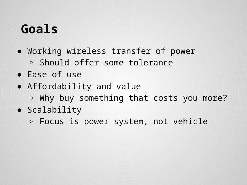
● Working wireless transfer of power○ Should offer some tolerance
● Ease of use● Affordability and value
○ Why buy something that costs you more?● Scalability
○ Focus is power system, not vehicle

Block Diagram
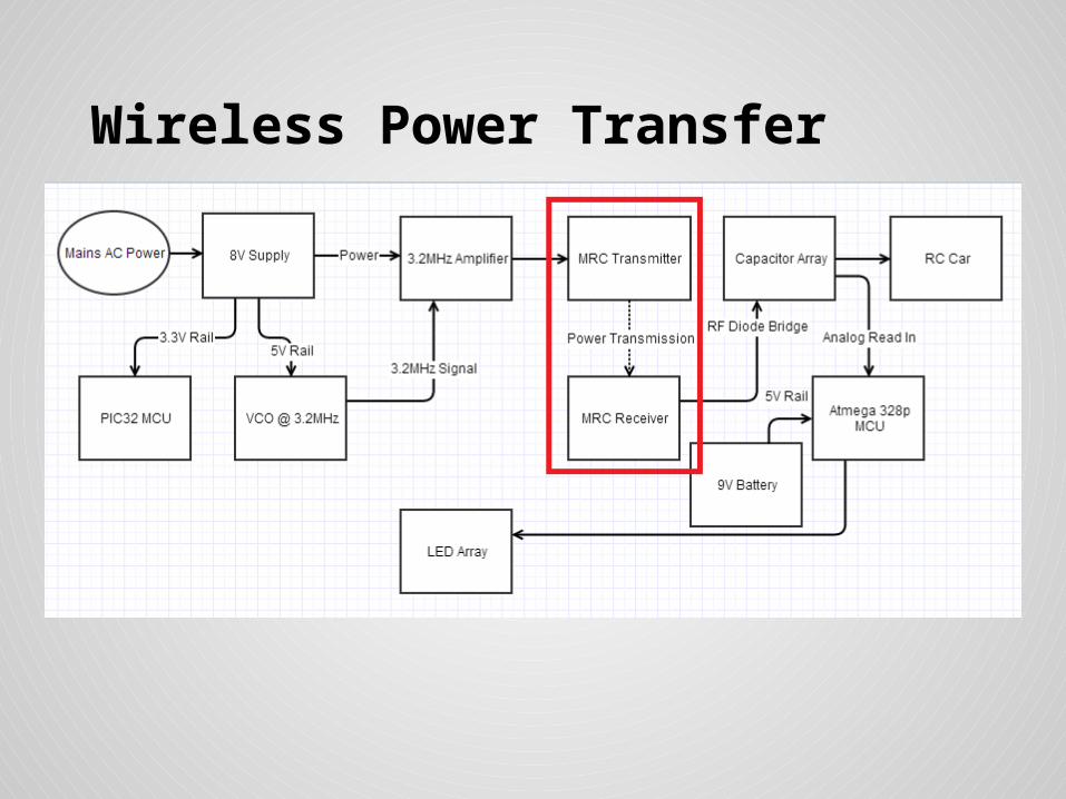
Wireless Power Transfer
Wireless Power Transfer
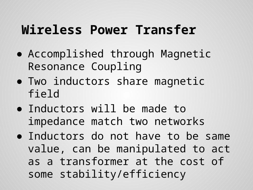
● Accomplished through Magnetic Resonance Coupling
● Two inductors share magnetic field● Inductors will be made to impedance match
two networks● Inductors do not have to be same value, can
be manipulated to act as a transformer at the cost of some stability/efficiency

Wireless Power Transfer
● Coil Selection:○ Etched Teflon Substrate (Planar Square Inductors)○ Wirewound
● Etched Teflon:○ Costly○ Time-consuming and permanent○ Very stable and precise
● Wirewound:○ Significantly cheaper○ Can be made quickly, can be altered○ Susceptible to vibration, not exact.

Wireless Power Transfer
Etched Teflon Substrate Model in HFSS
Illustration By Nick

Wireless Power Transfer
● Representative Circuit (Wirewound)

Wireless Power Transfer
● Resonant Coils act as air gap transformer
● Resonant coils must be separated at a distance less than 1 Length
● Equivalent Circuit Model:

Wireless Power Transfer
● Previous circuit worked, provided proof of concept
● Must be fine-tuned, >60% efficiency at the moment
● Oscilloscope measurements, Blue = output, yellow = input:

Generating a HF Power Signal

Generating a HF Power Signal
1. Generate a low power signal at our desired frequency.
2. Amplify the signal.

Power Signal Specifications
● Variable frequency from 1MHz to 20MHz for tuning, allowing manipulation of frequency based on needs
● 70%+ efficiency, but the higher the better.● More amperage = better, but must provide
minimum 15V swing for capacitor array later.

Producing the HF signal
● Positive feedback op-amp circuit○ Hartley Oscillator
● Voltage Controlled Oscillator
○ Texas Instruments SN74LS629
● Programmable Oscillator ○ MAXIM COM-09089
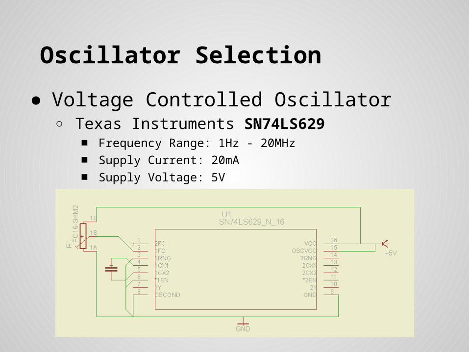
Oscillator Selection
● Voltage Controlled Oscillator ○ Texas Instruments SN74LS629
■ Frequency Range: 1Hz - 20MHz
■ Supply Current: 20mA
■ Supply Voltage: 5V
■ Easy to turn on/off with MCU

HF Power Amplifier
● Class D○ Switching amplifier utilizing 2 MOSFETS driven to be fully ‘on’ or ‘off’,
distorting the signal into more of a square wave, which isn’t too much of a problem for our application.
○ High efficiency, with theoretical efficiencies up to 100%. ○ Tend to run into problems with HF, such as our application.
● Class E
○ Very high efficiencies possible, such as over 90%.
Class D Topology Class E Topology

Class E Amplifier Design

Amplifier Selection Criteria
● Efficiency!● Performance in high frequencies ● Minimal components

MOSFET Selection
● Price● Input Capacitance ● Drain Current● Size?
Part Price Input Capacitance Max Id
STMicroelectronics LET20030C $83.20 58 pF 9A
EPC2012 $2.98 128 pF 3A
Vishay IRF510 $0.96 180 pF 5.6A

Concerns
● Enough current to drive the MOSFET at high frequencies. ○ A gate driver is a good solution
■ IXYS IXDN604PI● 8A peak output current● 40V operating range● 14ns rise/fall time equates to 38MHz max frequency

Non-ideal properties
• Class E Amplifier issueso In theory this is a great amplifier. In practice, it has many issues
Highly sensitive to frequency manipulation Must be very precisely balanced to work in our design
• Complete attenuation at ~5% deviation from specified value
• Circuit works far better than anticipated without load, doesn’t work at all with load
Works better without impedance matching• Calculation isn’t the issue, tolerance of affordable parts is
• Considerations for improvemento Class D Amplifier works nicely and isn’t as sensitive to matching
Requires twice as many parts to implement, requires two signals 180 degrees out of phase or a PMOS/NMOS pair
o Streamlined Class E Uses MRC network as resonant network of Class E Considerably more efficient in our implementation

Final Amplifier Circuit Design

Powering the RC Car (Supercaps)
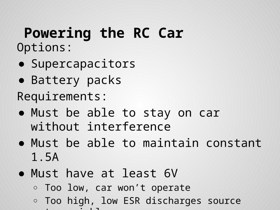
Powering the RC CarOptions:● Supercapacitors● Battery packs
Requirements:● Must be able to stay on car without
interference● Must be able to maintain constant 1.5A● Must have at least 6V
○ Too low, car won’t operate○ Too high, low ESR discharges source too quickly

RC Battery packsPros:● Inexpensive● Small form factor● Constant voltage
Cons:● Low lifespan and retention of charge● Heat● Slow charge speed

SupercapacitorsPros:
● Quick to charge, can be regulated
● Considerably longer lifespan
● Holds charge much longer
Cons:
● Costly
● Most of its potential charge speed is unusable in our design, requires large amount of power
● Cannot expel all of its stored charge

Maxwell BCAP0350 350F, 2.7V Cap● 350F (Not a typo) means large energy storage potential● 3 caps in array (series)
○ Makes an equivalent 8.1V tolerant cap● Rated at absolute max storage of 0.4Wh, array safely
used at 1Wh+ total charge● Roughly 0.8Wh useable energy (~10 mins operation)● Size of a D Cell battery● Exceeded expectations

Comparison of Capacitors

Why Supercaps?• Non-ideal charging circuit to justify supercaps: not nearly
as much current as possible, so why use them?o Added stability for the RC car
Increased power consumption on turns Future model may increase current draw Less energy burnt in ESR
o Ease of use/implementation Do not need to regulate full-wave rectified signal: the caps do this
automatically Easier to experiment with due to longer life span and faster charge Individual components allow more freedom in our design
• Can add more caps in parallel to increase energy content
Voltage greatly changes with consumption• MCU can more easily display energy remaining in caps

Final Measurements• MRC network can supply ~0.4-0.5A of current
o 1mV/sec on 350F caps Roughly 3600 seconds (1 hour) to go from 4.4V to 8.1V
o Car runs for roughly 10 minutes on full charge (full throttle w/ turns) Charge:Use ratio of roughly 6:1 (beats original 10:1 ratio of car)
• Much of this has to do with non-ideal propertieso MRC Network does not receive a large amount of current, but
increasing current only directs more current into MOSFET, not to MRC network.
o Caps/components could easily tolerate 2-3A, so potential future designs which increase current flow could supply more power as well.
o Voltage level is fine, supplies above caps’ max voltage to make sure charge rate does not diminish.

Supercapacitor Array

Enhanced Charging Speed● Caps can be charged even more quickly by
supplying a larger voltage○ Avoids exponential limit of charge rate○ Must be supervised (big cap = big boom)

Cap Charging Protector Circuit● Designed to protect caps from overcharge● Comparator stops charging before caps overcharge● To be implemented in MCU using digital logic

Microcontroller System

MCU justification
● To provide real-time feedback at key positions of the project
● Monitor the charge level of the capacitor array on car and warn user of overvoltage
● Output visual a indication of remaining energy on car
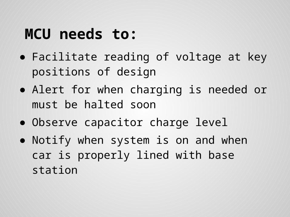
MCU needs to:
● Facilitate reading of voltage at key positions of design
● Alert for when charging is needed or must be halted soon
● Observe capacitor charge level
● Notify when system is on and when car is properly lined with base station

MCU Comparisons
Model Company Cost($) PackageOnboard Memory Size(kB)
Architecture Software cost I/O
LPC4088FET208
NXP $13.50 208 Ball pin SMD
512 ARM-M4 Too much165
MSP430F67791X
TI $6.48 100LQFPSMD
512 MSP430 227 for full CCP62
ATMEGA328P-PU
Atmel $3.23 28 pin DIP 32 32-bit AVR Free20
PIC32MX795F512L
MicroChip $11.00 100TQFPSMD
512 MIPS32 M4K Free83
PIC32MX250F128B
MicroChip $4.60 28 pin DIP 128 MIPS32 M4K Free19
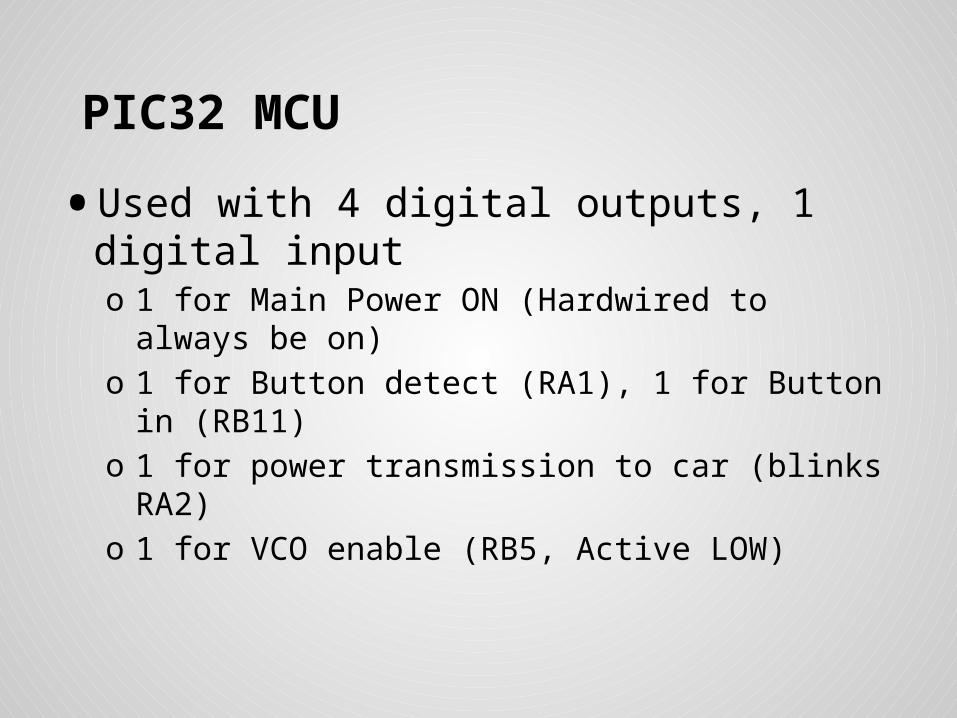
PIC32 MCU
• Used with 4 digital outputs, 1 digital inputo 1 for Main Power ON (Hardwired to always be on)o 1 for Button detect (RA1), 1 for Button in (RB11)o 1 for power transmission to car (blinks RA2)o 1 for VCO enable (RB5, Active LOW)

Data flow chartStation MCU system:

Charge Disconnection
● Button push will tell base when car is aligned
● If button is pressed, car is on station, which sends enable (Active LOW) to VCO, and when button is not pressed, remove enable signal (send HIGH to VCO)● Low power consumption when shutting off VCO (~5mW)

Atmega 328p• Easy to program for analog applications
o Arduino Platform uses Atmega 328p 28-pin ICo Two Analog inputs (A1 and A0) used in difference to
calculate voltage across cap arrayo 20 sample average taken to smooth results
• 9 digital pins (D2-D10) used for LED Arrayo 1 digital pin used for warning light (yellow to yellow
flashing)o LEDs light every 0.4V between 4.3V and 7.5V, Warning
Light on at 8Vo Last LED blinks to warn of low power below 4.3V
(Complete shutoff at 4.1-4.2V depending on load)

Display Information
● LED Array tells remaining voltage in 1/8ths of usable range
● Yellow Warning LED tells user if charging is complete (must be removed to avoid overvoltage on cap array)
● Same LED Array tells user how much charging has completed
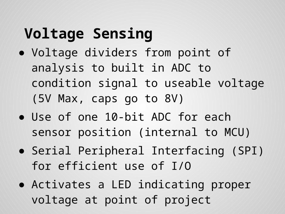
Voltage Sensing● Voltage dividers from point of analysis to built in
ADC to condition signal to useable voltage (5V Max, caps go to 8V)
● Use of one 10-bit ADC for each sensor position (internal to MCU)
● Serial Peripheral Interfacing (SPI) for efficient use of I/O
● Activates a LED indicating proper voltage at point of project

Data flow chartCar MCU system:

Power Supplies

Power Supply (Mains)Source of Power● Mains 120 Vrms, 60 Hz U.S. House Outlet● Single Power Supply (AC/DC Converter)
Requirements:
- Single positive Voltage Supply +8V
- Able to supply enough power for the circuit in its entirety without suffering significant current loss.

Circuit Diagram: Power Supply (Mains)

Power Consumption
● All measurements are approximate.
● Components not labeled are relatively insignificant (<0.1W).
● Consumes roughly 5W of power (heat in transformer indicates this is source of most loss).
● Aimed for 20W+ compliance to absolutely ensure proper operation and no need to worry about feedback.
● These are not expensive components and save the hassle of needing protective elements
Component Voltage (Volts) Current (Amps) Power (Watts)
Power Supply 8V 0.6 4.8W
Capacitor Array 4.4V -> 8V 0.5 -> 0.3 ~2.3W
Microcontroller 3.3 0.1 0.3
Signal Generator 5 .05 0.25

Power Supply (Mains)
Component Specifications Quantity
Step Down Transformer - 6.3Vrms at Center Tap (+8V peak tapped after rectification, 12.6Vrms untapped)
1
Diode Bridge/IC - Low Forward Voltage - Forward Current Max
at least 2-3A
1
Electrolytic Capacitor 40V tolerance, high capacitance (10mF)
1

High Frequency Power SupplyPurpose:Able to take high frequency AC signal (post WPT) and convert this to reliable DC signal.
Requirements:
● Output 15V DC and maintain acceptible current for quickly charging Super Cap. Array.
● Components MUST have a fast reverse recovery time. Simple diode rectifier bridge?????

High Frequency Power SupplyNOPE!
*Simple diodes at high frequencies exhibit capacitive attributes.*
Simple solution: RF Schottky Diodes
● Fabricated to operate at high frequencies.
● Extremely fast reverse recovery time will enable proper rectification high frequency input.

Schottky DiodesBridge Configuration:
● 4 Schottky Diodes for rectification
Requirements:● Must be be able to withstand at least 2 A of forward
current and have low forward voltage.● Must have a reverse recovery time relatively quicker
than 100ns.● Reverse Surge Voltage >= 40V

UC3610N
• Dual Schottky Diode Bridge made by Texas Instrumentso 70pF Junction capacitance (~14MHz max frequency)o 3A Max current, 50V Reverse Voltageo 0.5V Forward Voltage (1V @1A)o Works well at our frequency
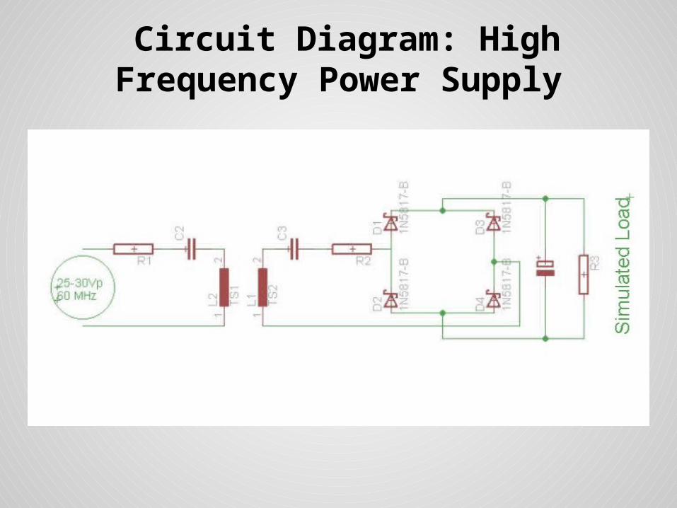
Circuit Diagram: High Frequency Power Supply

Workload Distribution
Brendan Nick Steven Jimmy
AC/DC Converters X
RF Signal Generator X
MRC Network/ Capacitor Array
X
MCU Implementation X

Budget

Questions?