mapal competence actuating tools en · 4 += in general, mapal provides a guarantee for the function...
TRANSCRIPT

A c t u a t i n g T o o l s
MAPAL Competence –Actuating Tools and Facing Heads

3
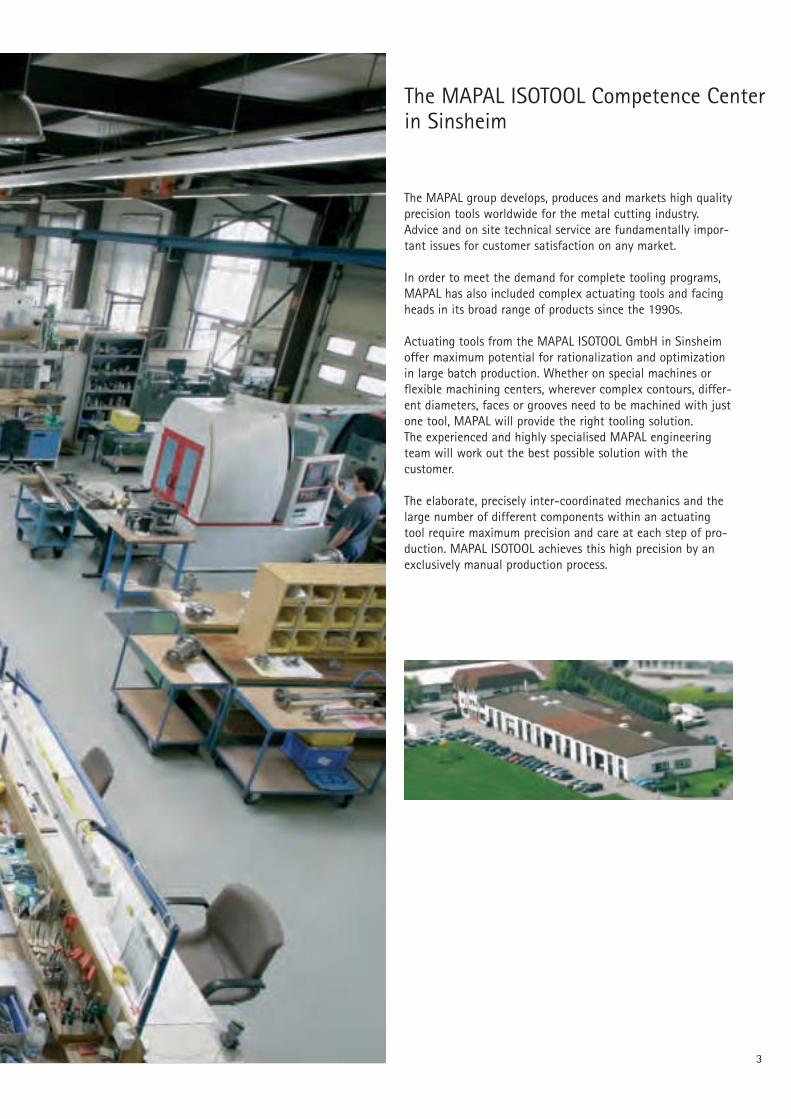
The MAPAL ISOTOOL Competence Centerin Sinsheim
The MAPAL group develops, produces and markets high qualityprecision tools worldwide for the metal cutting industry.Advice and on site technical service are fundamentally impor-tant issues for customer satisfaction on any market.
In order to meet the demand for complete tooling programs,MAPAL has also included complex actuating tools and facingheads in its broad range of products since the 1990s.
Actuating tools from the MAPAL ISOTOOL GmbH in Sinsheimoffer maximum potential for rationalization and optimizationin large batch production. Whether on special machines orflexible machining centers, wherever complex contours, differ-ent diameters, faces or grooves need to be machined with justone tool, MAPAL will provide the right tooling solution.The experienced and highly specialised MAPAL engineeringteam will work out the best possible solution with thecustomer.
The elaborate, precisely inter-coordinated mechanics and thelarge number of different components within an actuatingtool require maximum precision and care at each step of pro-duction. MAPAL ISOTOOL achieves this high precision by anexclusively manual production process.

4
+ =
In general, MAPAL provides a guarantee for the function of the actuating toolsdeveloped and produced. For critical trial tools, however, development is alwayscoordinated and concluded with the customer.In order to complete the installation of the tools at the customer’s works as quicklyand efficiently as possible, an extensive trials program is conducted for all actuatingtools under extreme stress and real application conditions.Installation is then carried out at the customer’s works by a MAPAL cutting toolspecialist.
Over the next few pages MAPAL will introduce a selection of typical complexactuating tools together with the proven series of standard facing heads which arealready in use worldwide.
The Combination is the thing ...
The MAPAL actuating tools with guide pads represent all our experiences in metal-cutting.New types of high performance tools emerged from proven technologies.
Development, design, production and service to thehighest precision provide the basis for products
from MAPAL..

5
+
=
MAPAL high-tech tools for higher product quality at reduced production costs.
Intr
oduc
tion
MAP
AL T
echn
olog
yAc
tuat
ing
prin
cipl
esSt
anda
rdfa
cing
hea
dsAc
tuat
ing
tool
sin
pra
ctic
e
MAPAL guide pad technology
Actuating tool technology
The combination is the thing ...4
Actuating tools for every machining task 6
IndexThe Competence CenterMAPAL ISOTOOL in Sinsheim 2
Function principlesActuating with draw bar 8Actuating with contact stop concept 9Actuating with centrifugal force 10Actuating with coolant pressure 11Actuating with Tooltronic 12
Machining examplesfor special machines 14for machining centers 17
MAPAL facing headsSurvey 21LAT ... 1 single slide 26LAT ... 2 parallel twin slide 28LAT ... C single slide with counter balance slide 30EAT facing head with eccentric actuating system 32Adaptation to customer requirements 34
Test stand for actuating tools.
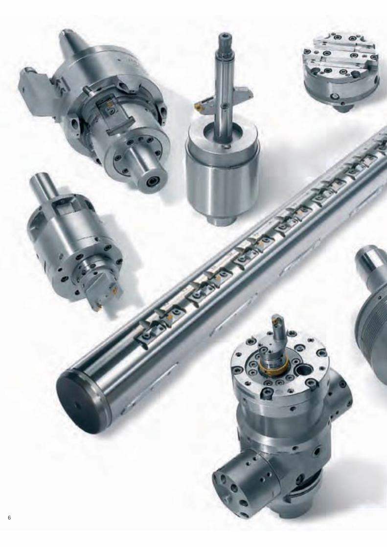
6
7
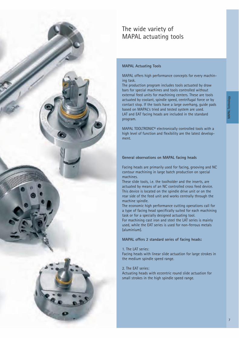
MAPAL Actuating Tools
MAPAL offers high performance concepts for every machin-ing task.The production program includes tools actuated by drawbars for special machines and tools controlled without external feed units for machining centers. These are toolsactuated by coolant, spindle speed, centrifugal force or bycontact stop. If the tools have a large overhang, guide padsbased on MAPAL’s tried and tested system are used.LAT and EAT facing heads are included in the standard program.
MAPAL TOOLTRONIC® electronically controlled tools with ahigh level of function and flexibility are the latest develop-ment.
General observations on MAPAL facing heads
Facing heads are primarily used for facing, grooving and NCcontour machining in large batch production on specialmachines.These slide tools, i.e. the toolholder and the inserts, are actuated by means of an NC controlled cross feed device.This device is located on the spindle drive unit or on the rear side of the feed unit and works centrally through themachine spindle.The economic high performance cutting operations call for a type of facing head specifically suited for each machiningtask or for a specially designed actuating tool.For machining cast iron and steel the LAT series is mainlyused, while the EAT series is used for non-ferrous metals(aluminium).
MAPAL offers 2 standard series of facing heads:
1. The LAT series:Facing heads with linear slide actuation for large strokes inthe medium spindle speed range.
2. The EAT series:Actuating heads with eccentric round slide actuation forsmall strokes in the high spindle speed range.
The wide variety of MAPAL actuating tools
MAP
AL T
echn
olog
y

8
F
Actuating with draw bars
- Mainly used on special machineswhich are not, or only seldom, refitted.
- Slide generating by means of anactuating bar, either drawing or pushing.
- Generating the actuating bar bymeans of an hydraulic or NC feedunit.
MAPAL actuating toolsFunction principle 1
Draw bar
Slide

9
F
Actuating with contact stop
- Slide generating is achieved byusing the workpiece surface or aspecial device as a contact stop.
- Special generating tools can mainly be used on machining centers with torque support.
MAPAL actuating toolsFunction principle 2
Resetting by spring force Workpiece
Rotary slide
Actu
atin
g pr
inci
ples
Actuating bar fixedby life center

10
Actuating with coolant pressure
- Tool feed can be set manually bymeans of a throttle valve.
- Coolant controlled tools are sub-ject to very low maintenance asthe coolant pressure is not applieddirectly on the moving parts butvia a membrane onto an oil padwhich then lubricates the movingparts.
- Advantage:A standard machine can be usedwithout special adjustment.
- Slide actuation is achieved by app-lying the existing coolant pressure.Normally coolant at 50 bar isrequired.
- Actuating tools can be used onmachining centers with the appro-priate level of coolant pressure.
MAPAL actuating toolsFunction principle 3
Slide
Membrane
Slide
Draw barCoolant pressure
Pressure valve
Oil
11
F
FZ
FZ
Oil
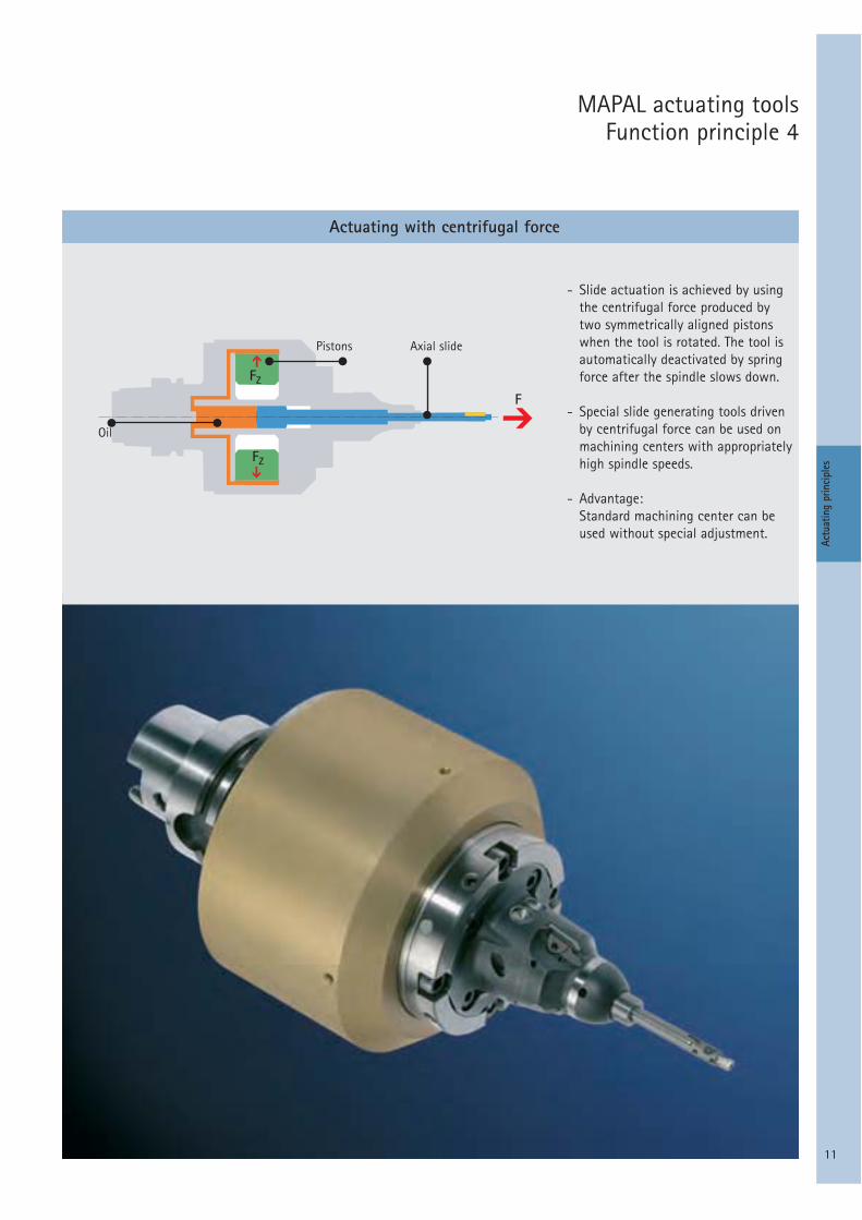
MAPAL actuating toolsFunction principle 4
Actuating with centrifugal force
- Slide actuation is achieved by usingthe centrifugal force produced bytwo symmetrically aligned pistonswhen the tool is rotated. The tool isautomatically deactivated by springforce after the spindle slows down.
- Special slide generating tools drivenby centrifugal force can be used onmachining centers with appropriatelyhigh spindle speeds.
- Advantage:Standard machining center can beused without special adjustment.
Axial slidePistons
Actu
atin
g pr
inci
ples

12
Actuating with TOOLTRONIC®
- Generating the slide is achieved bymeans of a servomotor in the tool.TOOLTRONIC® actuating tools can be used on machining centers or special machines. Machining com-plex contours is also possible on a machining center.
- Advantage:TOOLTRONIC® provides an additionalaxis for a machine.
MAPAL actuating toolsFunction principle 5
TOOLTRONIC® – The drivingforce in precision machining
MAPAL TOOLTRONIC® has been developedas a self-contained drive system. Byinductive and bi-directional data trans-mission, TOOLTRONIC® provides a full,additional NC-axis which is incorporatedinto the machine control system. Thismeans that the functions of modern CNCcontrol systems, such as interpolation ofdifferent axes and adjustment for wearand blade radius, can also be fully utilisedwhen TOOLTRONIC® is incorporated.
The new, fully-developed electronic sys-tem sets new standards in the inductivelytransferred power of mechatronic tools.Bi-directional data transmission alsoallows any sensor data to be transferredfrom TOOLTRONIC® to the machine con-trol, opening up new opportunities inmachining and control concepts.
The type of block tool to be used with TOOLTRONIC® depends on the actual machining task. In principle all self-generating tools from MAPAL ISOTOOL, which are activated by coolant pressure, centrifugal force, contact stop or draw bar, can be driven and controlled by TOOLTRONIC® as an alternative.
However, possible applications are not just limited to cutting with a geometrical-ly aligned blade. Combined with TOOLTRONIC®, a honing tool with self-generating honing pads to provide com-pensation for wear and dimensional adjustment becomes a block tool.
Stator
Motor
Electronics
Transmissionsystem

13
Contour machining with MAPAL TOOLTRONIC®
EAT head with boring and facing tool for turning contours
Valve guide reaming and valve seat turning with EAT head
Honing tool with self-generating honing pads for cylinder bores
Boring head with bladeadjustment for cylinderbores
LAT face slide tool with large radial stroke
Actu
atin
g pr
inci
ples

14
ø8 H
7
201.5
120
HSK 40
ø32
ø144
90
HUB 20
Internal machining with EAT facing head on special machines
MAPAL actuating toolsActuated by Draw bar
Machining values:vc = 250...425 m/minn = 10000 min-1
f cylindrical turning = 0.1 mm/revf recessing = 0.1 mm/rev
Description:Machining various diameters 8 – 13.5 mm in IT7 quality including machining recesses
Material: Gd-AlSi12 (Cu)
Slide boring bar for machining crankshaft bearing holes and thrust walls
Machining values:vc = 120 m/minn = 420 1/minf = 0,16 mm/U
Description :Tool for roughing and finishing ofcrankshaft journals and – withactuating element – for facing thethrust walls.

15
ø232ø6
0
745
1530
Line boring bar for cylinder bore
Feature:Nine machining steps combined on onework station.
Description:Semi-finishing and finishing includingall recesses and water jacket controlcuts for truck crankcases.
Material: CG26Cr
Actu
atin
g to
ols
in p
ract
ice
MAPAL actuating toolsActuated by Draw bar
Optional for 4 and 6 engine blocks
Material: Ci26 CuCr e SCI 60
16
ø83
212
ø176
125
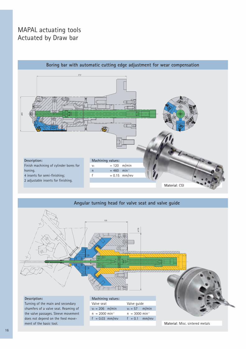
Boring bar with automatic cutting edge adjustment for wear compensation
Angular turning head for valve seat and valve guide
MAPAL actuating toolsActuated by Draw bar
Machining values:vc = 120 m/minn = 460 min-1
f = 0.15 mm/rev
Description:Finish machining of cylinder bores forhoning.4 inserts for semi-finishing; 2 adjustable inserts for finishing.
Material: CGI
Machining values:Valve seat Valve guidevc = 206 m/min vc = 57 m/minn = 2000 min-1 n = 3000 min-1
f = 0.03 mm/rev f = 0.1 mm/rev
Description:Turning of the main and secondarychamfers of a valve seat. Reaming ofthe valve passages. Sleeve movementdoes not depend on the feed move-ment of the basic tool. Material: Misc. sintered metals

17
ø29
ø29
314
200
ø120
ø120
178
75°
22Hub
EM#1
EM#2
ø12
3
ø128
.31
EM 71.23
235 ± 0.01
300
22Hub
Special actuating tool with contact stop for facing and recessing
Special generating tool for spherical machining
MAPAL actuating toolsActuated by contact stop
Machining values:vc = 120 m/minn = 300 min-1
f = 0.08 mm/rev
Description:Machining of the balcony depth andthe recess on a cylinder bore for amotor. Simultaneous machining of end face and recess acc. to DIN 509 – Form F. Material: cast iron CG25
Machining values:vc = 130 m/minn = 410...1300 min-1
f = 0.05 mm/rev
Description:Machining the spherical form in differential housings by contacting a life center bearing. Slide is reset by spring force.
Material: SCI 40
Actu
atin
g to
ols
in p
ract
ice

18
ø70
725
ø69
H7
364
Line boring bar for machining crankshaft bearing holes on machining centers
Line boring bar for machining thrust bearings on machining centers
MAPAL actuating toolsActuated by coolant pressure
Machining values:vc = 44 m/minn = 200 min-1
f = 0.08 mm/rev
Description:Tool for simultaneous machining of journals on machining centers. Guiding by means of carbide or PCD pads which can be actuated.
Material: SCI 75
Average machining values:vc = 95 m/minn = 320 min-1
f cylindrical turning = 0.15 mm/rev
Description:Tool for the facing of thrust bearings of cylindrical crankcases on machining centers.Supported in the workpiece by carbide or PCD pads. Material: SCI 75
19
333.42
230
76 45.5
27.3 ± 0.1
ø20
9.52
7283
°
+ 0.
084
ø125
ø125
218 270
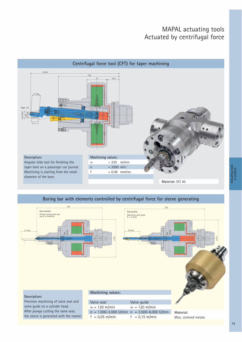
Centrifugal force tool (CFT) for taper machining
Taper 1:6
31 Hub
Boring bar with elements controlled by centrifugal force for sleeve generating
MAPAL actuating toolsActuated by centrifugal force
Machining values:vc = 230 m/minn = 3500 min-1
f = 0.08 mm/rev
Description:Angular slide tool for finishing the taper bore on a passenger car journal.Machining is starting from the small diameter of the bore.
Material: SCI 40
Description:Precision machining of valve seat and valve guide on a cylinder head.After plunge cutting the valve seat, the sleeve is generated with the reamer
Material:Misc. sintered metals
Actu
atin
g to
ols
in p
ract
ice
Start position
Plunge cutting valve seat(up to 3 chamfers)
End position
Machining valve guideD = 4...9mm
52 Hub 52 Hub
Gas
sprin
g
Gas
sprin
g
Machining values:
Valve seat Valve guidevc = 120 m/min vc = 120 m/minn = 1.000-3.000 U/min n = 3.500-6.000 U/minf = 0,05 m/min f = 0,15 m/min
20
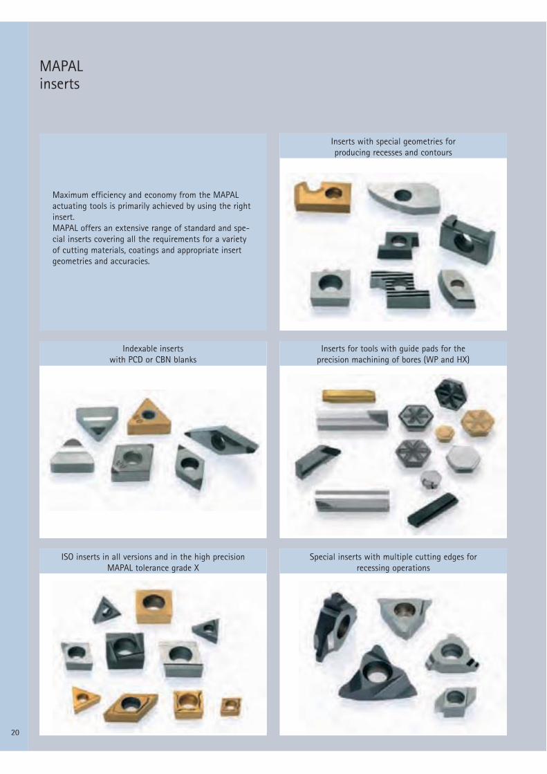
MAPAL inserts
Maximum efficiency and economy from the MAPALactuating tools is primarily achieved by using the rightinsert.MAPAL offers an extensive range of standard and spe-cial inserts covering all the requirements for a varietyof cutting materials, coatings and appropriate insertgeometries and accuracies.
Inserts with special geometries for producing recesses and contours
Inserts for tools with guide pads for the precision machining of bores (WP and HX)
Indexable inserts with PCD or CBN blanks
Special inserts with multiple cutting edges for recessing operations
ISO inserts in all versions and in the high precision MAPAL tolerance grade X

21
Stan
dard
faci
ng h
eads
MAPALfacing heads

22
Single slide
Parallel twin slide
MAPAL standard facing heads
LAT...1...
LAT...2...
Spindle speed range:low spindle speedsLAT…1…spindle speed limit:
2400nmax =Hub *
* slide stroke and change of center of gravity
Type of operation:Mainly internal machining, medium toheavy machining with maximum overallrigidity in the “slide – tool” system.
Spindle speed range:Medium spindle speeds.Important note: The traction forcedepends on spindle speed, stroke andtool weight.MAPAL ISOTOOL supplies calculationsfor the dimensions of the cross feeddevice.
Type of operation:In contrast to the standard “face turn-ing from outside to inside”, LAT…2…facing heads can also be supplied in asemi-standard version for “face turningfrom inside to outside”.

23
Single slide with counter balance
Rotary slide
MAPAL standardfacing heads
LAT...C...
EAT...
Spindle speed range:Medium spindle speedsImportant note: Traction depends onspindle speed, stroke and tool weight.MAPAL ISOTOOL supplies calculationsfor the dimensions of the cross feeddevice.
Type of operation:With the LAT…C… series the block toolsare designed for a specific weight andaligned on the covered counter-balanceslide.
Spindle speed range:high to maximum spindle speedsAdvantage: Very low machining forceson draw bar.
STan
dard
faci
ng h
eads

24
Machining tasks:
MAPAL standard facing heads
Boring Face turning
BoringGrooving
Boring with cutting edge lifting
Boring, facing, grooving (internal)
Contour turning, grooving (external)
Facing
Contour turning (internal) Grooving (external), centering function optional

25
MAPAL standard facing heads
The LAT facing heads
The EAT actuating heads
STan
dard
faci
ng h
eads
In conjunction with the relevantmechanical elements, the translatorydraw bar movement of the cross feeddevice is redirected in the EAT actuatinghead by a cam control system into arotary movement and produces the nec-essary swing motion by means of theexcentrically supported rotary slide.
Compared to the LAT system, EAT actu-ating heads require significantly lessactivating forces and drive power in astable, dynamically balanced situationand are, therefore, particularly suitedfor HSC machining.
Here the translatory draw bar move-ment of the cross feed device is redi-rected by the mechanical slide drive ele-ments into radial or angular actuatingmovements.
The application data – in particular thecutting speed – resulting from themachining task, provide appropriatedynamics at high spindle speeds. As thetraction depends on the spindle speedand the stroke, the performance of thecross feed device must be suitablydimensioned. MAPAL ISOTOOL providesthe appropriate support and the neces-sary calculations.

26
H L1
L2
L4
L3 Z max
Z maxT 1
L6 L5
d1 d2 d3 d4d5
Q m
axD
1
G1Q
max
A
C
40°
alphabeta
B
D1
E
Single slide facing headLAT...1...
Reference code: LAT-xxx-1-yyLAT Linear Actuating Tool
(facing head)
xxx head diameter = D1 with one (1) linear slideyy cross stroke = Qmax
LAT-xxx-1-yy

27
80 100 125 160 200 250 32010 17 22 32 40 50 63
11,92 20,26 26,22 38,14 47,67 59,59 75,0842 48 58 70 85 100 125
66,7 89 114 149 186 232 300M10x1 L.H. M10x1 L.H. M12x1,5 L.H. M16x1,5 L.H. M16x1,5 L.H. M20x1,5 L.H. M20x1,5 L.H.
12 12 14 18 18 25 2516 16 18 25 32 40 40
29,5 29,5 31,5 39,5 55,5 69,5 69,530 30 32 40 56 70 7046 62 73 93 125 153 168
31,08 38,74 43,78 50,86 72,33 88,41 87,926 8 10 10 10 20 303 3 3 4 5 5 58 12 12 12 12 15 1514 18 18 24 32 40 40
M6 (3x) M6 (4x) M6 (6x) M6 (8x) M8 (8x) M10 (8x) M12 (8x)7,5 14 14,8 13 15 21 29- - - 15° 15° 15° 15°- 35° 35° 45° 45° 45° 50°
3 x 120° - - - - - -
70 83 103 128 160 200 25736 40 56 70 90 110 13012 12 14 17 19 24 2828 35 42 60 76 94 107
LAT-080-1-10 LAT-100-1-17 LAT-125-1-22 LAT-160-1-32 LAT-200-1-40 LAT-250-1-50 LAT-320-1-63
D
Qmax
Zmax
H
D1
d1
d2H7
d3
d4
d5 j5
L1
L2
L3
L4
L5
L6
G1
T1
alpha
beta
gamma
A
B
C
E
Reference codes
Single slide facing headLAT...1...
Mai
n
dim
ensi
ons
Conn
ectio
n di
men
sion
s
Slid
e
dim
ensi
ons
STan
dard
faci
ng h
eads

28
H L1
L2
L4
L3 Z max
Z maxT 1
L6 L5
d1 d2 d3 d4d5
Q m
axD
1
G1
Q m
ax
A1
D1
40°
alpha 1
beta 1
B1
B2
Parallel double slide facing headLAT...2...
Reference code: LAT-xxx-2-yyLAT Linear Actuating Tool
(facing head)
xxx head diameter = D2 with 2 opposite linear
slideyy cross stroke = Qmax
LAT-xxx-2-yy

29
LAT-100-2-17 LAT-125-2-22 LAT-160-2-32 LAT-200-2-40 LAT-250-2-50 LAT-320-2-63
100 125 160 200 250 32017 22 32 40 50 63
20,26 26,22 38,14 47,67 59,59 75,0848 58 70 85 100 125
89 114 149 186 232 300M10x1 L.H. M12x1,5 L.H. M16x1,5 L.H. M16x1,5 L.H. M20x1,5 L.H. M20x1,5 L.H.
12 14 18 18 25 2516 18 25 32 40 40
29,5 31,5 39,5 55,5 69,5 69,530 32 40 56 70 7062 73 93 125 153 168
38,74 43,78 50,86 72,33 88,41 87,928 10 10 10 20 303 3 4 5 5 512 12 12 12 15 1518 18 24 32 40 40
M6 (4x) M6 (6x) M6 (8x) M8 (8x) M10 (8x) M12 (8x)14 14,8 13 15 21 29- 0° 15° 15° 15° 15°
35° 35° 45° 45° 45° 50°
83 103 128 158 200 25753 68 80 102 115 14519 24 28 36 40 52,5
D
Qmax
Zmax
H
D1
d1
d2H7
d3
d4
d5 j5
L1
L2
L3
L4
L5
L6
G1
T1
alpha
beta
A1
B1
B2
Parallel double slide facing headLAT...2...
Reference codes
Mai
n
dim
ensi
ons
Conn
ectio
n di
men
sion
s
Slid
e
dim
ensio
ns
STan
dard
faci
ng h
eads
30
H L1
L2
L4
L3 Z max
Z max
T 1
L6 L5
d1 d2 d3 d4d5
Q m
axD
1
G1Q
max
A
D1
40°
alpha beta
C
B
E
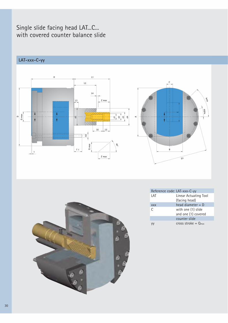
Single slide facing head LAT...C... with covered counter balance slide
Reference code: LAT-xxx-C-yyLAT Linear Actuating Tool
(facing head) xxx head diameter = DC with one (1) slide
and one (1) coveredcounter slide
yy cross stroke = Qmax
LAT-xxx-C-yy

31
LAT-100-C-12 LAT-125-C-16 LAT-160-C-24 LAT-200-C-32 LAT-250-C-40
D
Qmax
Zmax
H
D1
d1
d2H7
d3
d4
d5 j5
L1
L2
L3
L4
L5
L6
G1
T1
alpha
beta
A
B
C
E
100 125 160 200 25012 16 24 32 40
14,3 19,07 28,6 38,14 47,6774 92 105 123 145
89 114 149 186 232M10x1 L.H. M12x1,5 L.H. M16x1,5 L.H. M16x1,5 L.H. M20x1,5 L.H.
12 14 18 18 2516 18 25 32 40
29,5 31,5 39,5 55,5 69,530 32 40 56 7056 73 93 125 141
38,7 50,93 60,4 81,86 88,338 10 20 10 203 3 4 5 512 12 12 12 1518 18 24 24 40
M6 (4x) M6 (6x) M6 (8x) M8 (8x) M10 (8x)12 14 12,5 17 17- 0° 15° 15° 15°
35° 35° 45° 45° 45°
88 109 136 168 21040 56 70 90 11014 14 19 22 2430 36 52 66 90
STan
dard
faci
ng h
eads
Single slide facing head LAT...C...with covered counter balance slide
Reference codes
Mai
n
dim
ensi
ons
Slid
e
dim
ensi
ons
32
MBA
MBD
NSL
BH
KH
SL
BL LH
L3
L2 L1
7
KD AD
G3
E
TK1
ZD BD
G2 D1 SD
HSKZL
NSANSA
NSB
QH
30°
SW
Drive key (shown out
of position)
Counterweight to block tool
Interfering contour – counterweight
Wrench accesss –
high HSK drive key
End position,
bar pushed
Cutting edge end
position, bar
drawn
0° bis 36°
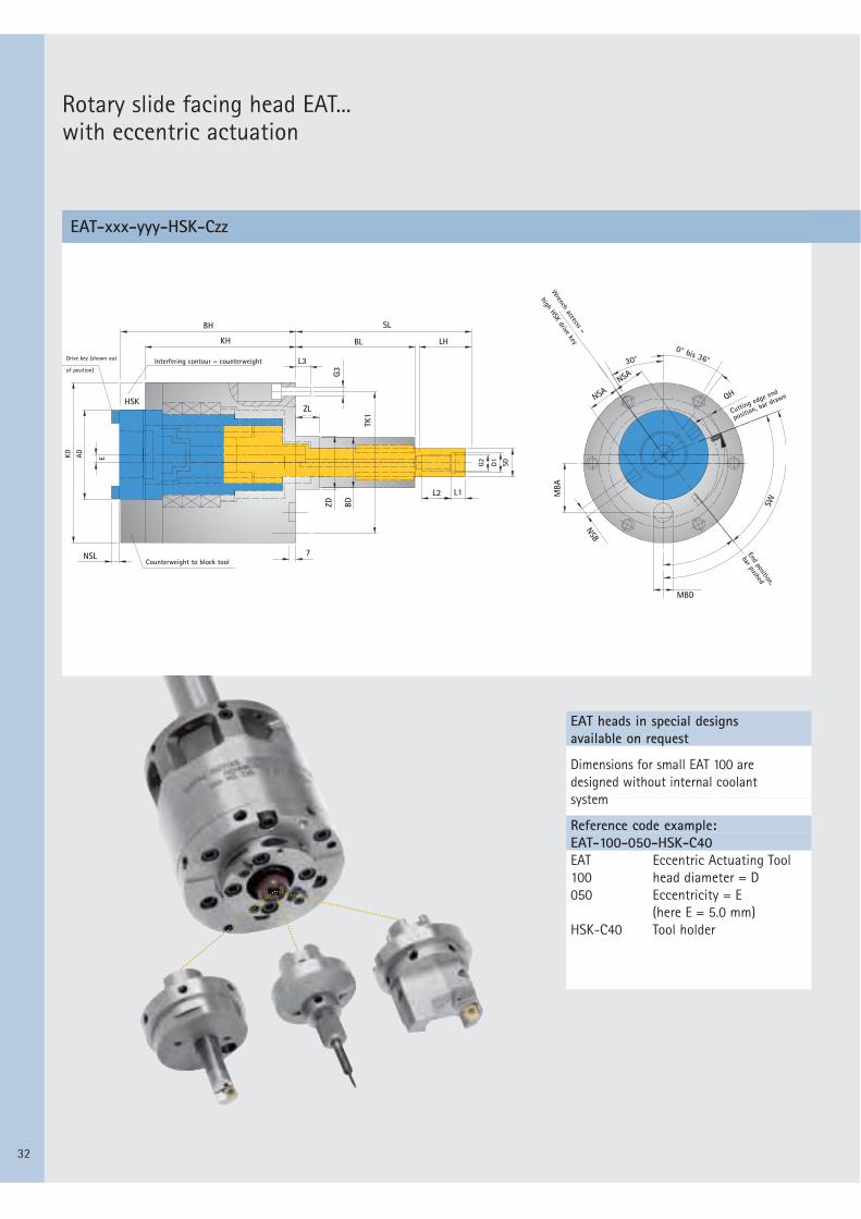
Rotary slide facing head EAT... with eccentric actuation
EAT heads in special designs available on request
Dimensions for small EAT 100 aredesigned without internal coolant system
Reference code example:EAT-100-050-HSK-C40EAT Eccentric Actuating Tool100 head diameter = D050 Eccentricity = E
(here E = 5.0 mm)HSK-C40 Tool holder
EAT-xxx-yyy-HSK-Czz
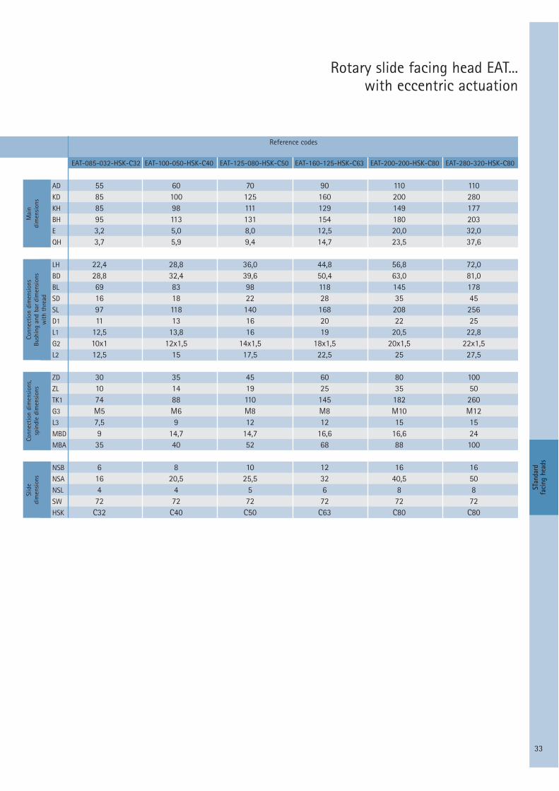
33
EAT-085-032-HSK-C32 EAT-100-050-HSK-C40 EAT-125-080-HSK-C50 EAT-160-125-HSK-C63 EAT-200-200-HSK-C80 EAT-280-320-HSK-C80
AD
KD
KH
BH
E
QH
LH
BD
BL
SD
SL
D1
L1
G2
L2
ZD
ZL
TK1
G3
L3
MBD
MBA
NSB
NSA
NSL
SW
HSK
55 60 70 90 110 11085 100 125 160 200 28085 98 111 129 149 17795 113 131 154 180 2033,2 5,0 8,0 12,5 20,0 32,03,7 5,9 9,4 14,7 23,5 37,6
22,4 28,8 36,0 44,8 56,8 72,028,8 32,4 39,6 50,4 63,0 81,069 83 98 118 145 17816 18 22 28 35 4597 118 140 168 208 25611 13 16 20 22 25
12,5 13,8 16 19 20,5 22,810x1 12x1,5 14x1,5 18x1,5 20x1,5 22x1,512,5 15 17,5 22,5 25 27,5
30 35 45 60 80 10010 14 19 25 35 5074 88 110 145 182 260M5 M6 M8 M8 M10 M127,5 9 12 12 15 159 14,7 14,7 16,6 16,6 2435 40 52 68 88 100
6 8 10 12 16 1616 20,5 25,5 32 40,5 504 4 5 6 8 872 72 72 72 72 72
C32 C40 C50 C63 C80 C80
STan
dard
faci
ng h
eads
Rotary slide facing head EAT... with eccentric actuation
Reference codes
Mai
ndi
men
sion
sCo
nnec
tion
dim
ensi
ons
Bush
ing
and
bar
dim
ensi
ons
with
thr
ead
Conn
ectio
n di
men
sion
s,sp
indl
e di
men
sion
sSl
ide
dim
ensi
ons

34
d6 d7 d8 d9 L7 L8 L9 V S R h6
S
L8
L2 Zmax L9V
L7 R
L8
L2Zmax L9VL7
d4d7d9
d6
d4d7d8
d6
M24x1,5 19 13 17 8 74 11 17 8,2 6M24x1,5 19 13 17 12 90 11 17 8,2 6M27x1,5 19 15 17 18 105 13 19 8,2 6M33x1,5 26 19 21 20,5 133 13 27 10,2 10M45x1,5 33 19 26 32,5 172 15 32 12,2 10M56x1,5 41 26 33 38 210 19 38 15,2 12M56x1,5 41 26 33 36 225 19 38 15,2 12
M24x1,5 19 13 17 12 90 11 17 8,2 6M27x1,5 19 15 17 18 105 13 19 8,2 6M33x1,5 26 19 21 20,5 133 13 27 10,2 10M45x1,5 33 19 26 32,5 172 15 32 12,2 10M56x1,5 41 26 33 38 210 19 38 15,2 12M56x1,5 41 26 33 36 225 19 38 15,2 12
M24x1,5 19 13 17 12 84 11 17 8,2 6M27x1,5 19 15 17 18 105 13 19 8,2 6M33x1,5 26 19 21 30 133 13 27 10,2 10M45x1,5 33 19 26 42 172 15 32 12,2 10M56x1,5 41 26 33 38 198 19 38 15,2 12
LAT-080-1-10LAT-100-1-17LAT-125-1-22LAT-160-1-32LAT-200-1-40LAT-250-1-50LAT-320-1-63
LAT-100-2-17LAT-125-2-22LAT-160-2-32LAT-200-2-40LAT-250-2-50LAT-320-2-63
LAT-100-C-12LAT-125-C-16LAT-160-C-24LAT-200-C-32LAT-250-C-40
Tooth angle / translation ratio
Adjustments to customer requirements
Draw bar designed with bayonet coupling and stop Drawbar designed with stop
Depending on the machining task and the machine requirements, the following variations can be supplied as semi-standards without additional charge.
40° – tooth angle – standard45° – tooth angle 1:138° – tooth angle 1:1.226.565° – tooth angle 1:2
Radial stroke,slide
Axial stroke, draw bar
Tooth angle
Reference codes Special design

35
B
d D
STan
dard
faci
ng h
eads
Adjustments to customer requirements
Adaptor flanges for standard spindle heads and for special spindles available on request
Tool holder design – hole pattern for tool fixing
- flange connection- short, stable block tool- only inserts are changed
- HSK- Rapid tool change- can be preset- good tool change
accuracy
- ABS- Rapid tool change- can be preset
- flange connection- tool can also be
changed rapidly
Code:D flange diameterLK hole circle diameterd centering diameterB flange thickness
LAT...1 and LAT...C LAT...2
LK-Ø

36
AST-
E-01
-020
-030
8-M
ZPr
inte
d in
Ger
man
y/Ri
ght
of t
echn
ical
mod
ifica
tions
res
erve
d.
Reaming and Fine BoringFrom the wide range of single and twin-bladed reamers with guide pads, together with fine boring tools with guide pads and WP or HX blades, to the HPR High Performance Reamers combined with the MAPAL HFS® Head Fitting System for exact concentricity and accurate changeover – to give you a general view of our complete knowledge and experience in pre cision machining bores.
PCD ToolsFor pre-machining and finish machining, MAPAL also offers an extensive programme of pre cision tools with fixed PCD (polycrystalline diamond) blades. This includes precision gun boring tools plus circular and end milling tools. The programme of face milling heads from the PowerMill and EcoMill series is characterised by simple, sturdy design and rapid, accurate blade setting.
ISO ToolsThis aspect of MAPAL competence is made up of special tools with ISO elements for gun boring and milling. This includes precision ground blades in the widest variety of cutting materials and coatings. The use of MAPAL's tried and tested adjustment system ensures that the blades are accurately matched to the task. MAPAL offers particular knowledge and ex -perience in tangential technology.
Actuating Slide ToolsActuating slide tools offer a high potential for rationalisation and optimisation on special machines and machining centres. In addition to the conventional facing heads, MAPAL also supplies EAT and LAT performance-enhanced actuating systems for generating slide tools. MAPAL TOOLTRONIC® tools with their extraordinary range of functions are the latest develop-ment.
DrillingYet another area is the product programme for drilling. MAPAL offers the right tool concept for every task, whether for machining aluminium, steel or cast iron, hard machining or dry machining or for use in HSC areas. Specially developed coatings and drills with PCD bladescomplete the broad-based drilling programme.
ClampingMAPAL's modern clamping systems, in conjunction with MAPAL's tried and tested reaming and fine boring tools, guarantee maximum productivity and economy. Whether HSK, ISO or HFS®, these high-precision connections and interfaces provide the concentricity and change-over accuracy essential to modern production.
Customer ServicesProject planning, maintenance, management and optimisation – the complete CTS® service package from MAPAL will accompany you from process design to permanent process optimi-sation and will ensure optimum and cost-saving use of your tools with the best possible results.
A Review of MAPAL’s Competence
MAPAL Präzisionswerkzeuge Dr. Kress KGP.O. Box 1520 • D-73405 AalenPhone +49 (0) 73 61 / 5 85-0 • Fax +49 (0) 73 61 / 5 85-1 [email protected] • www.mapal.com