manual trans overhaul - saab 5-speed transaxle …saabrally.com/downloads/trnsm900_90.pdf · manual...
TRANSCRIPT
MANUAL TRANS OVERHAUL - SAAB 5-SPEED TRANSAXLEArticle Text
1990 Saab 900For 123 123 123 123 123
© 1997 Mitchell Repair Information Company, All Rights Reserved.Friday, October 15, 1999 04:40PM
ARTICLE BEGINNING
MANUAL TRANSMISSIONS Saab 5-Speed Transaxle
APPLICATION
TRANSMISSION APPLICATIONÄÄÄÄÄÄÄÄÄÄÄÄÄÄÄÄÄÄÄÄÄÄÄÄÄÄÄÄÄÄÄÄÄÄÄÄÄÄÄÄÄÄÄÄÄÄÄÄÄÄÄÄÄÄÄÄÄÄÄÄVehicle Application Transmission Model
1983-86 900S (Turbo 16 Valve) ................... GM-457061983-92 900 ..................................... GM-456061986-92 900 Turbo ............................... GM-456061986-92 900S (Turbo 16 Valve) ................... GM-55712ÄÄÄÄÄÄÄÄÄÄÄÄÄÄÄÄÄÄÄÄÄÄÄÄÄÄÄÄÄÄÄÄÄÄÄÄÄÄÄÄÄÄÄÄÄÄÄÄÄÄÄÄÄÄÄÄÄÄÄÄ
IDENTIFICATION
All Saabs with manual transmissions use a 5-speed transaxle.The Identification number is stamped on top of the clutch slavecylinder. The 1st character of the ID number (G) designates manualtransaxle. The 3rd character of the ID number (5) designates number offorward gears.
DESCRIPTION
The transaxle assembly is a 2-piece unit, containing bothtransmission and final drive assemblies. It is located underneath theengine. A portion of the transmission case serves as engine oil sump.Transmission and final drive are assembled in rear section oftransaxle. Primary gear unit is housed in front section. All forward gears are in constant mesh, while reverse gear isengaged by a sliding gear. A chain-driven primary gear unit transmitsengine power through the clutch to the transmission. Final driveassembly consists of differential assembly, pinion shaft, and driveaxle shaft housings.
NOTE: Ensure any gears being replaced match old gears. Noise and durability problems will result if incorrect gears are used.
LUBRICATION & ADJUSTMENT
See appropriate TRANSMISSION SERVICING - M/T article in theMANUAL TRANS SERVICE section.
TROUBLE SHOOTING
See TROUBLE SHOOTING - BASIC PROCEDURES in the GENERALTROUBLE SHOOTING section.
MANUAL TRANS OVERHAUL - SAAB 5-SPEED TRANSAXLEArticle Text (p. 2)
1990 Saab 900For 123 123 123 123 123
© 1997 Mitchell Repair Information Company, All Rights Reserved.Friday, October 15, 1999 04:40PM
SERVICE (IN VEHICLE)
DRIVE AXLE SHAFTS
See appropriate AXLE SHAFT - FRONT article in DRIVE AXLESsection.
TRANSAXLE MOUNTS
Removal & Installation 1) Place transmission in Neutral. Unbolt exhaust pipe frommanifold. Disconnect speedometer cable from transmission. Remove rearengine mounting bolt. Loosen front engine mounting bolt. 2) Attach hoist to 2 lifting rings. Raise engine andtransaxle assembly about 4". Remove bolts attaching front and rearmounts to frame. Remove mounts. To install mounts, reverse removalprocedure.
REMOVAL & INSTALLATION
TRANSAXLE
See appropriate TRANSMISSION REMOVAL & INSTALLATION - M/Tarticle in the MANUAL TRANS SERVICE section.
* For 1983 900, see TRANSMISSION REMOVAL & INSTALLATION - M/T * For 1984 900, see TRANSMISSION REMOVAL & INSTALLATION - M/T * For 1985 900, see TRANSMISSION REMOVAL & INSTALLATION - M/T * For 1986 900, see TRANSMISSION REMOVAL & INSTALLATION - M/T * For 1987 900, see TRANSMISSION REMOVAL & INSTALLATION - M/T
TRANSAXLE DISASSEMBLY
NOTE: Prior to disassembly of transmission gears, measure and record ring-to-pinion gear backlash and pinion depth. See PINION DEPTH ADJUSTMENT.
1) Place transaxle assembly on work stand and drain fluid.Remove primary gear housing front and side covers. Remove oil fillerplug cover and final drive cover. Measure and record ring-to-piniongear backlash and pinion depth. Remove axle shaft housing attachingbolts. Using puller, remove housings.
NOTE: When removing axle housings, do not lose spring and plunger located in end of inner shaft. Also, note number and thickness of adjusting shims installed with housings.
MANUAL TRANS OVERHAUL - SAAB 5-SPEED TRANSAXLEArticle Text (p. 3)
1990 Saab 900For 123 123 123 123 123
© 1997 Mitchell Repair Information Company, All Rights Reserved.Friday, October 15, 1999 04:40PM
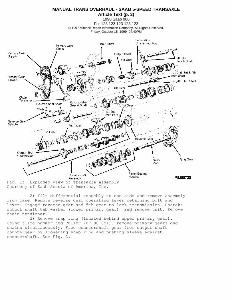
Fig. 1: Exploded View of Transaxle AssemblyCourtesy of Saab-Scania of America, Inc.
2) Tilt differential assembly to one side and remove assemblyfrom case. Remove reverse gear operating lever retaining bolt andlever. Engage reverse gear and 5th gear to lock transmission. Unstakeoutput shaft tab washer (lower primary gear), and remove unit. Removechain tensioner. 3) Remove snap ring (located behind upper primary gear).Using slide hammer and Puller (87 90 891), remove primary gears andchains simultaneously. Free countershaft gear from output shaftcountergear by loosening snap ring and pushing sleeve againstcountershaft. See Fig. 2.
MANUAL TRANS OVERHAUL - SAAB 5-SPEED TRANSAXLEArticle Text (p. 4)
1990 Saab 900For 123 123 123 123 123
© 1997 Mitchell Repair Information Company, All Rights Reserved.Friday, October 15, 1999 04:40PM
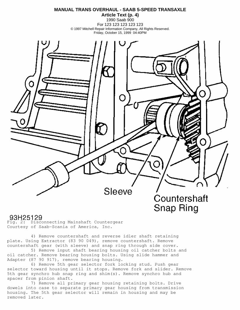
Fig. 2: Disconnecting Mainshaft CountergearCourtesy of Saab-Scania of America, Inc.
4) Remove countershaft and reverse idler shaft retainingplate. Using Extractor (83 90 049), remove countershaft. Removecountershaft gear (with sleeve) and snap ring through side cover. 5) Remove input shaft bearing housing oil catcher bolts andoil catcher. Remove bearing housing bolts. Using slide hammer andAdapter (87 90 917), remove bearing housing. 6) Remove 5th gear selector fork locking stud. Push gearselector toward housing until it stops. Remove fork and slider. Remove5th gear synchro hub snap ring and shim(s). Remove synchro hub andspacer from pinion shaft. 7) Remove all primary gear housing retaining bolts. Drivedowels into case to separate primary gear housing from transmissionhousing. The 5th gear selector will remain in housing and may beremoved later.
MANUAL TRANS OVERHAUL - SAAB 5-SPEED TRANSAXLEArticle Text (p. 5)
1990 Saab 900For 123 123 123 123 123
© 1997 Mitchell Repair Information Company, All Rights Reserved.Friday, October 15, 1999 04:40PM
8) Remove countershaft assembly with needle bearings andthrust washer identified for installation in original position. Removeselector shafts (from front) and selectors. Remove 1st and 2nd gearselectors together with respective synchro unit. 9) Reverse selector should be removed while still attached toselector shaft. Remove selector ball, guide pin, reverse idler shaftand reverse idler gear. Remove 4 pinion shaft bearing housingretaining screws. Using Remover (87 90 909), press out pinion.
CLEANING & INSPECTION
Clean all gasket material from covers and flanges. Afterwashing parts, inspect for unusual wear and discoloration. Check forknicks or chips of mating surfaces. Ensure mating surfaces are flatand smooth.
COMPONENT DISASSEMBLY & REASSEMBLY
PINION SHAFT
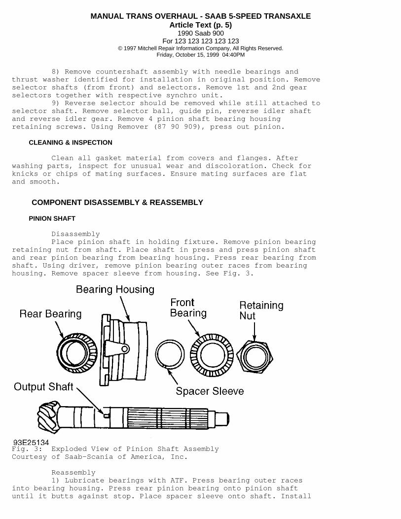
Disassembly Place pinion shaft in holding fixture. Remove pinion bearingretaining nut from shaft. Place shaft in press and press pinion shaftand rear pinion bearing from bearing housing. Press rear bearing fromshaft. Using driver, remove pinion bearing outer races from bearinghousing. Remove spacer sleeve from housing. See Fig. 3.
Fig. 3: Exploded View of Pinion Shaft AssemblyCourtesy of Saab-Scania of America, Inc.
Reassembly 1) Lubricate bearings with ATF. Press bearing outer racesinto bearing housing. Press rear pinion bearing onto pinion shaftuntil it butts against stop. Place spacer sleeve onto shaft. Install

MANUAL TRANS OVERHAUL - SAAB 5-SPEED TRANSAXLEArticle Text (p. 6)
1990 Saab 900For 123 123 123 123 123
© 1997 Mitchell Repair Information Company, All Rights Reserved.Friday, October 15, 1999 04:40PM
housing over sleeve. 2) Place front bearing on shaft and position shaft in press.Turn housing by hand. Slowly press bearing into housing untilresistance is felt. Remove shaft from press. 3) Coat bearing retaining nut threads with Loctite andinstall nuts, but do not tighten. Install pinion shaft assembly inholding fixture and place in vise. Attach spring pull gauge tohousing. See Fig. 4.
Fig. 4: Checking Pinion Bearing PreloadCourtesy of Saab-Scania of America, Inc.
4) Tighten retaining nut until force required to rotatehousing is 10-15 lbs. (4.5-6.8 kg) for new bearings or 4.2-9.2 lbs.(1.9-4.2 kg) for used bearings (1200 miles or more). When correctvalue is obtained, stake retaining nut.
NOTE: Pinion bearing preload is set to correct specification with retaining nut correctly tightened.
PRIMARY GEAR HOUSING
Disassembly Remove 4 Allen head screws from input shaft bearing retainerand remove retainer. Drive out bearing using Drift (83 90 106) andSleeve (83 90 148). Remove needle bearing from primary gear case usinga drift. Pry out input shaft oil seal. Remove upper primary gear snapring. Using Sleeve (87 90 842), press bearing out of upper primarygear.
NOTE: DO NOT remove lever control ball valve. Check that ball moves freely and securely sets on seat. Ball acts at low speeds while going down hills to prevent oil from running from gear case into primary gear housing.
Reassembly Inspect all parts for wear or damage and replace as
MANUAL TRANS OVERHAUL - SAAB 5-SPEED TRANSAXLEArticle Text (p. 7)
1990 Saab 900For 123 123 123 123 123
© 1997 Mitchell Repair Information Company, All Rights Reserved.Friday, October 15, 1999 04:40PM
necessary. Press in new input shaft oil seal and needle bearing (markfacing outward in housing). Press input shaft bearing into housing.Install bearing retainer. Apply Loctite to Allen head screw threads.Install and tighten screws.
OUTPUT SHAFT BEARING HOUSING
Disassembly Remove oil catcher from bearing housing. Being careful not todamage lubrication connection pipe, use Support (83 90 098) and pressoutput shaft from bearing housing. Retain front bearing, spacer andshims. Using Support (87 90 636) and Ring (87 90 933), press rearbearing off output shaft. Using drift, remove bearing outer races frombearing housing.
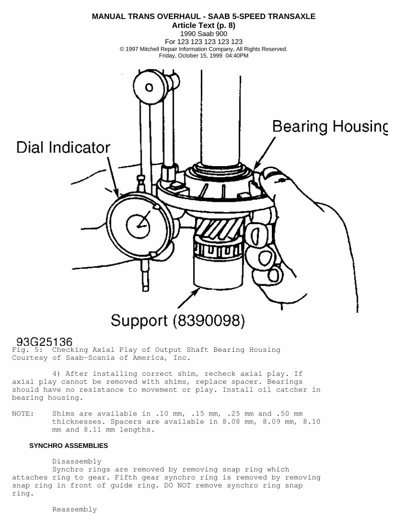
Reassembly 1) Press rear bearing onto output shaft. Press outer racesinto bearing housing. Install output shaft, shims, spacer and bearinginto bearing housing. Shims must be installed between rear bearing andspacer. 2) Lubricate bearings and press together using Support (83 90098) and Drift (78 41 075). While pressing, use 3 tons (2722 kg)pressure. Rotate bearing housing against upper and lower bearings 40times in each direction to seat ball bearings. 3) Install dial indicator. See Fig. 5. Maintain installationpressure and check axial play of bearing housing. Adjust axial play to0 by inserting correct shim.
MANUAL TRANS OVERHAUL - SAAB 5-SPEED TRANSAXLEArticle Text (p. 8)
1990 Saab 900For 123 123 123 123 123
© 1997 Mitchell Repair Information Company, All Rights Reserved.Friday, October 15, 1999 04:40PM
Fig. 5: Checking Axial Play of Output Shaft Bearing HousingCourtesy of Saab-Scania of America, Inc.
4) After installing correct shim, recheck axial play. Ifaxial play cannot be removed with shims, replace spacer. Bearingsshould have no resistance to movement or play. Install oil catcher inbearing housing.
NOTE: Shims are available in .10 mm, .15 mm, .25 mm and .50 mm thicknesses. Spacers are available in 8.08 mm, 8.09 mm, 8.10 mm and 8.11 mm lengths.
SYNCHRO ASSEMBLIES
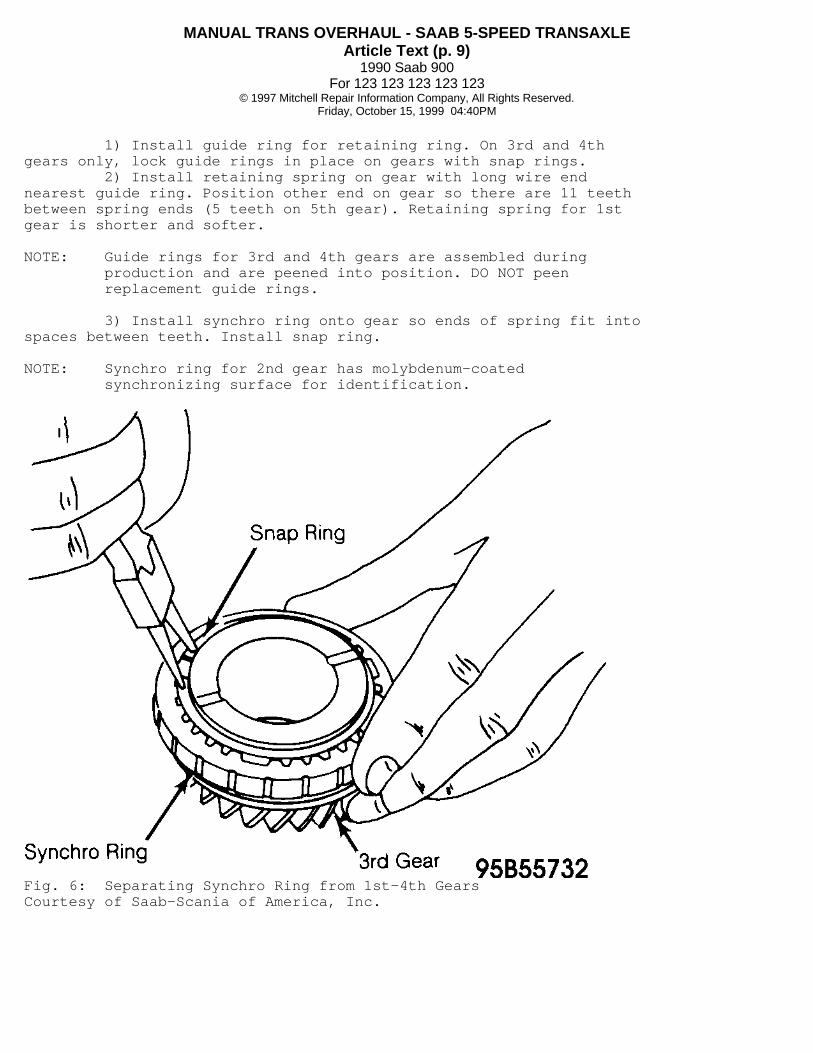
Disassembly Synchro rings are removed by removing snap ring whichattaches ring to gear. Fifth gear synchro ring is removed by removingsnap ring in front of guide ring. DO NOT remove synchro ring snapring.
Reassembly
MANUAL TRANS OVERHAUL - SAAB 5-SPEED TRANSAXLEArticle Text (p. 9)
1990 Saab 900For 123 123 123 123 123
© 1997 Mitchell Repair Information Company, All Rights Reserved.Friday, October 15, 1999 04:40PM
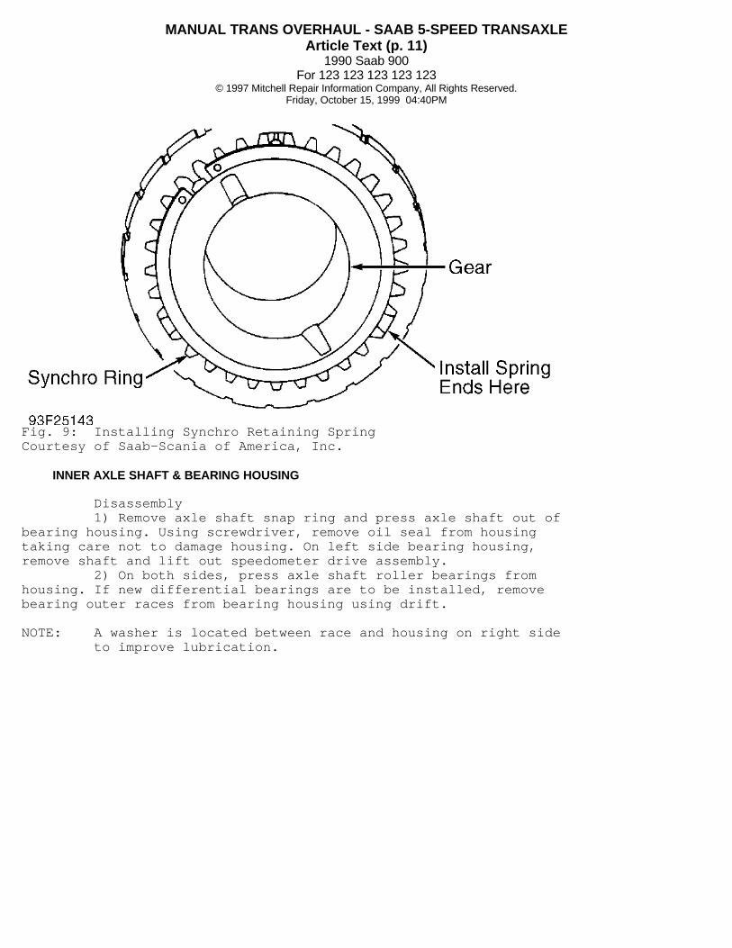
1) Install guide ring for retaining ring. On 3rd and 4thgears only, lock guide rings in place on gears with snap rings. 2) Install retaining spring on gear with long wire endnearest guide ring. Position other end on gear so there are 11 teethbetween spring ends (5 teeth on 5th gear). Retaining spring for 1stgear is shorter and softer.
NOTE: Guide rings for 3rd and 4th gears are assembled during production and are peened into position. DO NOT peen replacement guide rings.
3) Install synchro ring onto gear so ends of spring fit intospaces between teeth. Install snap ring.
NOTE: Synchro ring for 2nd gear has molybdenum-coated synchronizing surface for identification.
Fig. 6: Separating Synchro Ring from 1st-4th GearsCourtesy of Saab-Scania of America, Inc.

MANUAL TRANS OVERHAUL - SAAB 5-SPEED TRANSAXLEArticle Text (p. 10)
1990 Saab 900For 123 123 123 123 123
© 1997 Mitchell Repair Information Company, All Rights Reserved.Friday, October 15, 1999 04:40PM
Fig. 7: Exploded View of 1st-2nd Gear SynchroCourtesy of Saab-Scania of America, Inc.
Fig. 8: Exploded View of 3rd Gear SynchroCourtesy of Saab-Scania of America, Inc.
MANUAL TRANS OVERHAUL - SAAB 5-SPEED TRANSAXLEArticle Text (p. 11)
1990 Saab 900For 123 123 123 123 123
© 1997 Mitchell Repair Information Company, All Rights Reserved.Friday, October 15, 1999 04:40PM
Fig. 9: Installing Synchro Retaining SpringCourtesy of Saab-Scania of America, Inc.
INNER AXLE SHAFT & BEARING HOUSING
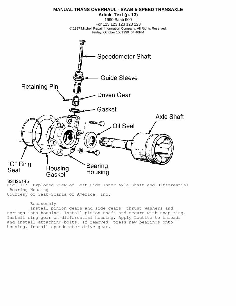
Disassembly 1) Remove axle shaft snap ring and press axle shaft out ofbearing housing. Using screwdriver, remove oil seal from housingtaking care not to damage housing. On left side bearing housing,remove shaft and lift out speedometer drive assembly. 2) On both sides, press axle shaft roller bearings fromhousing. If new differential bearings are to be installed, removebearing outer races from bearing housing using drift.
NOTE: A washer is located between race and housing on right side to improve lubrication.

MANUAL TRANS OVERHAUL - SAAB 5-SPEED TRANSAXLEArticle Text (p. 12)
1990 Saab 900For 123 123 123 123 123
© 1997 Mitchell Repair Information Company, All Rights Reserved.Friday, October 15, 1999 04:40PM
Fig. 10: Removing Axle Shaft Snap Ring From HousingCourtesy of Saab-Scania of America, Inc.
Reassembly Press new axle shaft bearing into housing. Installlubrication washer on right side. Press new differential bearing outerraces into bearing housing. Using drift, press bearing housing oilseal into housing until it protrudes .08" (2 mm) above face ofhousing.
NOTE: Axle shafts will be installed during TRANSAXLE REASSEMBLY & ADJUSTMENT.
DIFFERENTIAL ASSEMBLY
Disassembly 1) If differential bearings require replacement, removespeedometer drive gear from left side. Use puller to remove bearingsfrom differential housing. 2) Remove ring gear bolts and separate ring gear fromdifferential. Remove snap ring and press out pinion shaft. Removepinion gears, side gears, thrust washers and gear springs fromhousing.
MANUAL TRANS OVERHAUL - SAAB 5-SPEED TRANSAXLEArticle Text (p. 13)
1990 Saab 900For 123 123 123 123 123
© 1997 Mitchell Repair Information Company, All Rights Reserved.Friday, October 15, 1999 04:40PM
Fig. 11: Exploded View of Left Side Inner Axle Shaft and Differential Bearing HousingCourtesy of Saab-Scania of America, Inc.
Reassembly Install pinion gears and side gears, thrust washers andsprings into housing. Install pinion shaft and secure with snap ring.Install ring gear on differential housing. Apply Loctite to threadsand install attaching bolts. If removed, press new bearings ontohousing. Install speedometer drive gear.

MANUAL TRANS OVERHAUL - SAAB 5-SPEED TRANSAXLEArticle Text (p. 14)
1990 Saab 900For 123 123 123 123 123
© 1997 Mitchell Repair Information Company, All Rights Reserved.Friday, October 15, 1999 04:40PM
Fig. 12: Exploded View of Differential AssemblyCourtesy of Saab-Scania of America, Inc.
TRANSAXLE REASSEMBLY & ADJUSTMENT
PINION DEPTH ADJUSTMENT
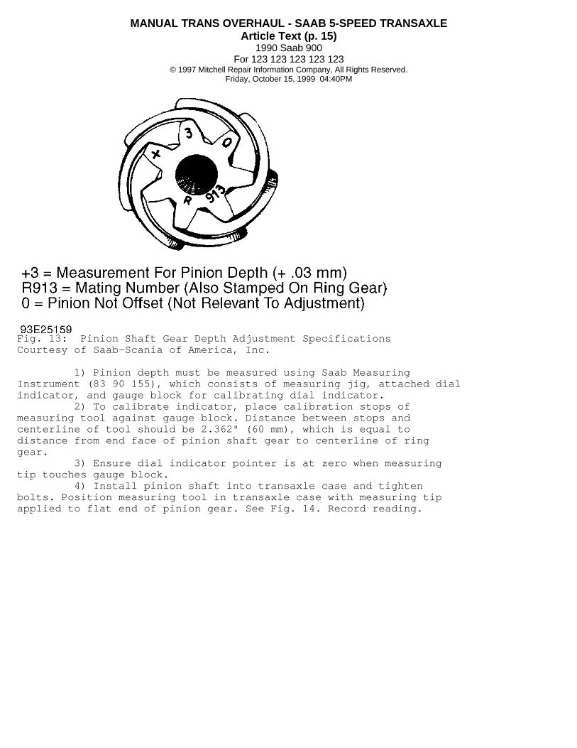
NOTE: Pinion bearing preload must be correctly adjusted before adjusting pinion depth. See PINION SHAFT REASSEMBLY. Metric Pinion Depth Adjustment specifications are stamped into end face of pinion shaft gear. See Fig. 13.
MANUAL TRANS OVERHAUL - SAAB 5-SPEED TRANSAXLEArticle Text (p. 15)
1990 Saab 900For 123 123 123 123 123
© 1997 Mitchell Repair Information Company, All Rights Reserved.Friday, October 15, 1999 04:40PM
Fig. 13: Pinion Shaft Gear Depth Adjustment SpecificationsCourtesy of Saab-Scania of America, Inc.
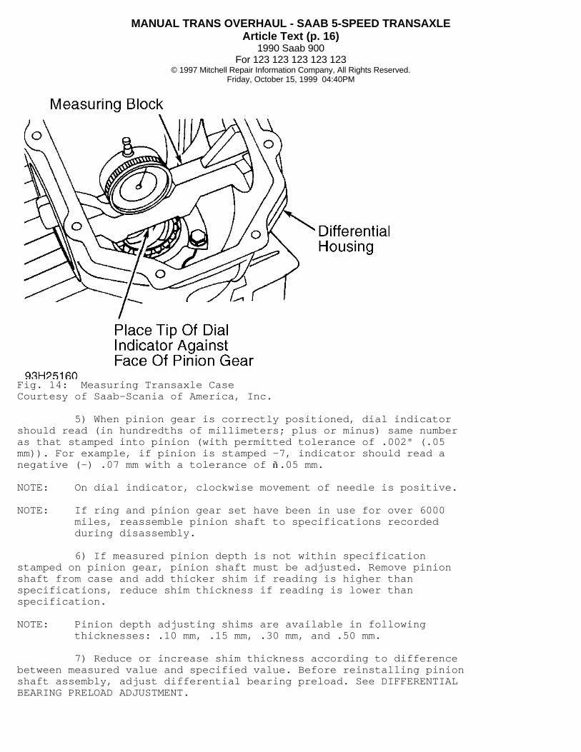
1) Pinion depth must be measured using Saab MeasuringInstrument (83 90 155), which consists of measuring jig, attached dialindicator, and gauge block for calibrating dial indicator. 2) To calibrate indicator, place calibration stops ofmeasuring tool against gauge block. Distance between stops andcenterline of tool should be 2.362" (60 mm), which is equal todistance from end face of pinion shaft gear to centerline of ringgear. 3) Ensure dial indicator pointer is at zero when measuringtip touches gauge block. 4) Install pinion shaft into transaxle case and tightenbolts. Position measuring tool in transaxle case with measuring tipapplied to flat end of pinion gear. See Fig. 14. Record reading.
MANUAL TRANS OVERHAUL - SAAB 5-SPEED TRANSAXLEArticle Text (p. 16)
1990 Saab 900For 123 123 123 123 123
© 1997 Mitchell Repair Information Company, All Rights Reserved.Friday, October 15, 1999 04:40PM
Fig. 14: Measuring Transaxle CaseCourtesy of Saab-Scania of America, Inc.
5) When pinion gear is correctly positioned, dial indicatorshould read (in hundredths of millimeters; plus or minus) same numberas that stamped into pinion (with permitted tolerance of .002" (.05mm)). For example, if pinion is stamped -7, indicator should read anegative (-) .07 mm with a tolerance of ñ.05 mm.
NOTE: On dial indicator, clockwise movement of needle is positive.
NOTE: If ring and pinion gear set have been in use for over 6000 miles, reassemble pinion shaft to specifications recorded during disassembly.
6) If measured pinion depth is not within specificationstamped on pinion gear, pinion shaft must be adjusted. Remove pinionshaft from case and add thicker shim if reading is higher thanspecifications, reduce shim thickness if reading is lower thanspecification.
NOTE: Pinion depth adjusting shims are available in following thicknesses: .10 mm, .15 mm, .30 mm, and .50 mm.
7) Reduce or increase shim thickness according to differencebetween measured value and specified value. Before reinstalling pinionshaft assembly, adjust differential bearing preload. See DIFFERENTIALBEARING PRELOAD ADJUSTMENT.
MANUAL TRANS OVERHAUL - SAAB 5-SPEED TRANSAXLEArticle Text (p. 17)
1990 Saab 900For 123 123 123 123 123
© 1997 Mitchell Repair Information Company, All Rights Reserved.Friday, October 15, 1999 04:40PM
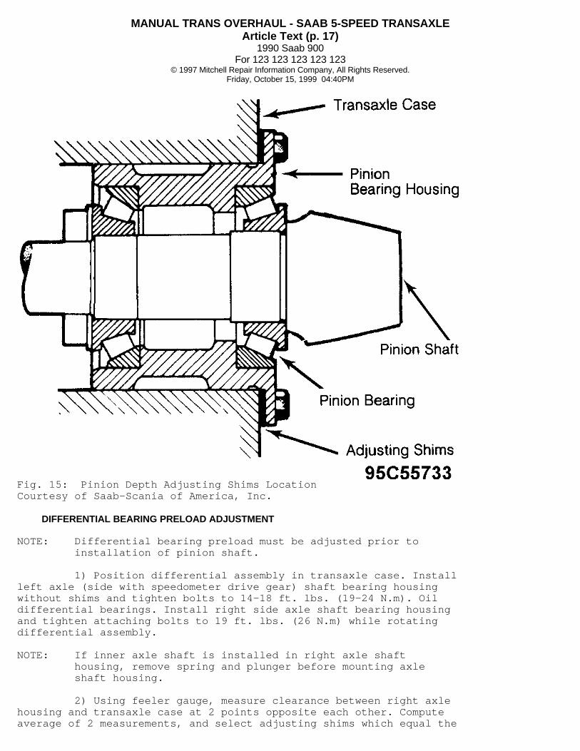
Fig. 15: Pinion Depth Adjusting Shims LocationCourtesy of Saab-Scania of America, Inc.
DIFFERENTIAL BEARING PRELOAD ADJUSTMENT
NOTE: Differential bearing preload must be adjusted prior to installation of pinion shaft.
1) Position differential assembly in transaxle case. Installleft axle (side with speedometer drive gear) shaft bearing housingwithout shims and tighten bolts to 14-18 ft. lbs. (19-24 N.m). Oildifferential bearings. Install right side axle shaft bearing housingand tighten attaching bolts to 19 ft. lbs. (26 N.m) while rotatingdifferential assembly.
NOTE: If inner axle shaft is installed in right axle shaft housing, remove spring and plunger before mounting axle shaft housing.
2) Using feeler gauge, measure clearance between right axlehousing and transaxle case at 2 points opposite each other. Computeaverage of 2 measurements, and select adjusting shims which equal the

MANUAL TRANS OVERHAUL - SAAB 5-SPEED TRANSAXLEArticle Text (p. 18)
1990 Saab 900For 123 123 123 123 123
© 1997 Mitchell Repair Information Company, All Rights Reserved.Friday, October 15, 1999 04:40PM
average. Add an additional .008" (.2 mm) in shim thickness to obtaincorrect bearing preload. 3) Measure bearing preload using an INCH lb. torque wrench.Preload for new, slightly oiled bearings should be 16-24 INCH lbs. (1.8-2.7 N.m). Preload for used bearings (1200 miles or more) should be7-11 INCH lbs. (.79-1.24 N.m).
NOTE: Right-to-left distribution of shims will be determined during RING GEAR BACKLASH ADJUSTMENT. Up to 4 shims may be combined to obtain correct preload. Shims are available in the following thicknesses: .10 mm, .15 mm, .30 mm and .50 mm.
RING GEAR BACKLASH ADJUSTMENT
NOTE: Ring gear adjustment specifications (in metric) are stamped onto ring gear. See Fig. 16. If ring and pinion gear set have been in use for over 6000 miles, reassemble differential according to specifications recorded during disassembly. Install pinion shaft with shims in housing.
Fig. 16: Ring Gear Backlash Adjustment SpecificationsCourtesy of Saab-Scania of America, Inc.
1) Place differential assembly into transaxle case. Installleft side (speedometer drive gear side) axle shaft bearing housing totransaxle case without adjusting shims and tighten attaching bolts to14-18 ft. lbs. (19-24 N.m). Install right side axle shaft bearinghousing along with selected bearing preload adjusting shims. Tightenattaching bolts.
MANUAL TRANS OVERHAUL - SAAB 5-SPEED TRANSAXLEArticle Text (p. 19)
1990 Saab 900For 123 123 123 123 123
© 1997 Mitchell Repair Information Company, All Rights Reserved.Friday, October 15, 1999 04:40PM
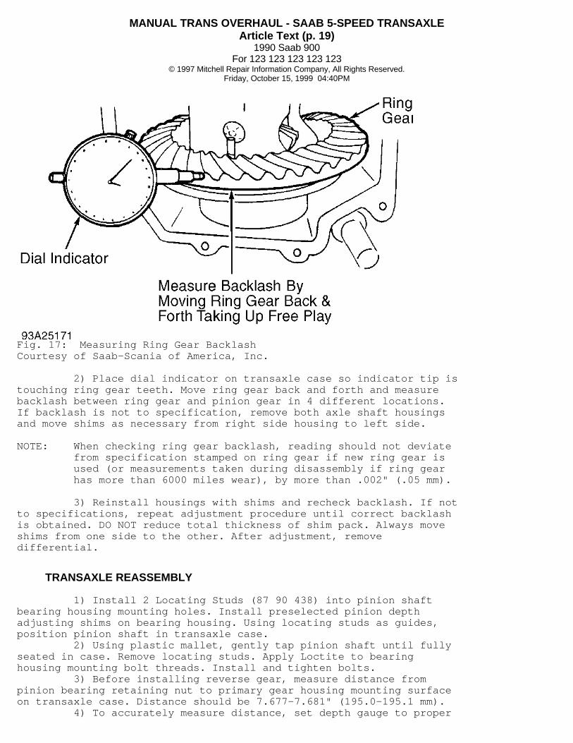
Fig. 17: Measuring Ring Gear BacklashCourtesy of Saab-Scania of America, Inc.
2) Place dial indicator on transaxle case so indicator tip istouching ring gear teeth. Move ring gear back and forth and measurebacklash between ring gear and pinion gear in 4 different locations.If backlash is not to specification, remove both axle shaft housingsand move shims as necessary from right side housing to left side.
NOTE: When checking ring gear backlash, reading should not deviate from specification stamped on ring gear if new ring gear is used (or measurements taken during disassembly if ring gear has more than 6000 miles wear), by more than .002" (.05 mm).
3) Reinstall housings with shims and recheck backlash. If notto specifications, repeat adjustment procedure until correct backlashis obtained. DO NOT reduce total thickness of shim pack. Always moveshims from one side to the other. After adjustment, removedifferential.
TRANSAXLE REASSEMBLY
1) Install 2 Locating Studs (87 90 438) into pinion shaftbearing housing mounting holes. Install preselected pinion depthadjusting shims on bearing housing. Using locating studs as guides,position pinion shaft in transaxle case. 2) Using plastic mallet, gently tap pinion shaft until fullyseated in case. Remove locating studs. Apply Loctite to bearinghousing mounting bolt threads. Install and tighten bolts. 3) Before installing reverse gear, measure distance frompinion bearing retaining nut to primary gear housing mounting surfaceon transaxle case. Distance should be 7.677-7.681" (195.0-195.1 mm). 4) To accurately measure distance, set depth gauge to proper
MANUAL TRANS OVERHAUL - SAAB 5-SPEED TRANSAXLEArticle Text (p. 20)
1990 Saab 900For 123 123 123 123 123
© 1997 Mitchell Repair Information Company, All Rights Reserved.Friday, October 15, 1999 04:40PM
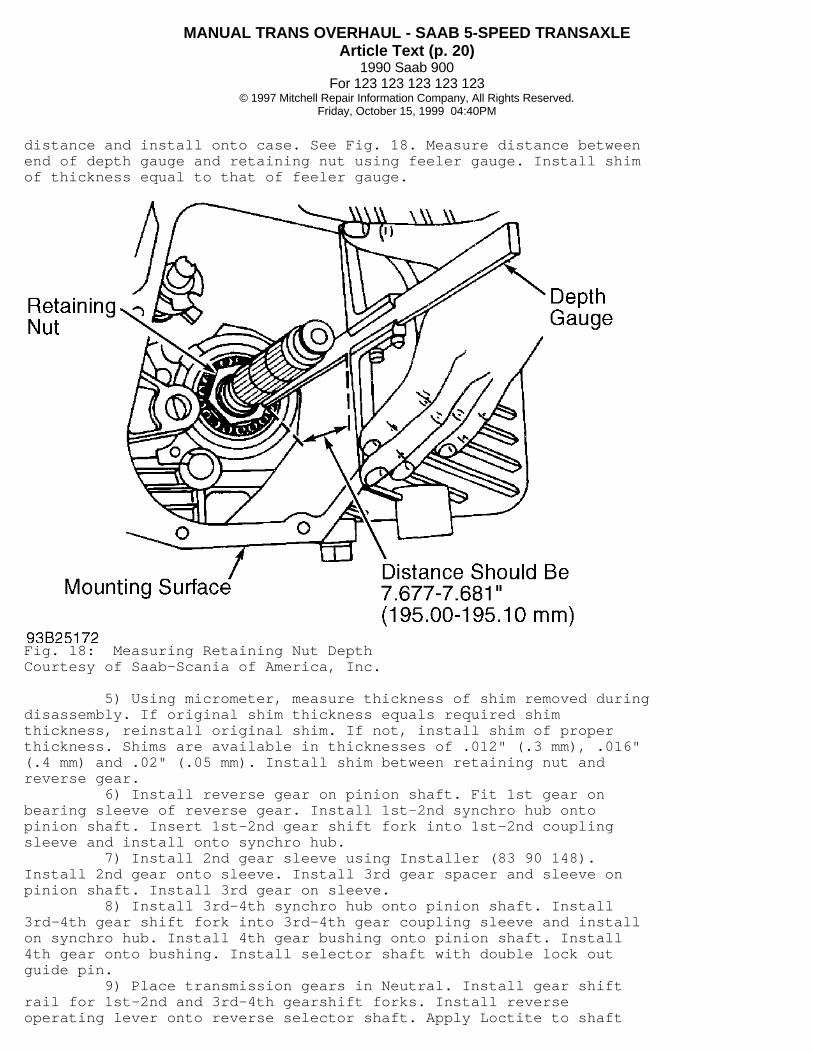
distance and install onto case. See Fig. 18. Measure distance betweenend of depth gauge and retaining nut using feeler gauge. Install shimof thickness equal to that of feeler gauge.
Fig. 18: Measuring Retaining Nut DepthCourtesy of Saab-Scania of America, Inc.
5) Using micrometer, measure thickness of shim removed duringdisassembly. If original shim thickness equals required shimthickness, reinstall original shim. If not, install shim of properthickness. Shims are available in thicknesses of .012" (.3 mm), .016"(.4 mm) and .02" (.05 mm). Install shim between retaining nut andreverse gear. 6) Install reverse gear on pinion shaft. Fit 1st gear onbearing sleeve of reverse gear. Install 1st-2nd synchro hub ontopinion shaft. Insert 1st-2nd gear shift fork into 1st-2nd couplingsleeve and install onto synchro hub. 7) Install 2nd gear sleeve using Installer (83 90 148).Install 2nd gear onto sleeve. Install 3rd gear spacer and sleeve onpinion shaft. Install 3rd gear on sleeve. 8) Install 3rd-4th synchro hub onto pinion shaft. Install3rd-4th gear shift fork into 3rd-4th gear coupling sleeve and installon synchro hub. Install 4th gear bushing onto pinion shaft. Install4th gear onto bushing. Install selector shaft with double lock outguide pin. 9) Place transmission gears in Neutral. Install gear shiftrail for 1st-2nd and 3rd-4th gearshift forks. Install reverseoperating lever onto reverse selector shaft. Apply Loctite to shaft
MANUAL TRANS OVERHAUL - SAAB 5-SPEED TRANSAXLEArticle Text (p. 21)
1990 Saab 900For 123 123 123 123 123
© 1997 Mitchell Repair Information Company, All Rights Reserved.Friday, October 15, 1999 04:40PM
stop bolt. Install and tighten stop bolt. Install 5th gear selectoronto reverse selector shaft. 10) Install countershaft gear needle bearing intocountershaft gear. Install countershaft gear into housing. Whilealigning countershaft, install countershaft gear shaft just enough tohold gears in position. Thrust washer will be installed later. 11) Install 5th gear spacer, 5th gear synchro hub and snapring onto pinion shaft. Measure distance between coupling sleeve andhub using feeler gauge so there is no play between parts on pinionshaft. Shims are available in .012" (.3 mm) and .016" (.4 mm)thicknesses. 12) Remove snap ring, hub and spacer. Apply sealing compoundto gasket surfaces of primary gear housing. Install gasket and housingto transmission housing. 13) Install spacer and 5th gear synchro hub on output shaft.Install shims selected to provide zero play between parts on shaft.Install snap ring, 5th gear operating sleeve and selector fork. 14) Install 3 Output Shaft Guide Pins (87 90 438) into lowerprimary gear bearing housing mounting bolt holes. Insert output shaftwith bearing housing, oil catcher and oil connecting pipe installed onAdapter (87 90 917). Install lower primary gear socket between adapterand bearing housing. 15) Using slide hammer, insert bearing housing and outputshaft assembly so bearing housing is seated and output shaft meetsoperating sleeve. Install output shaft countershaft thrust washer,coated with grease, so tab fits into recess of case. 16) Slide output shaft countergear onto shaft and installsleeve, bearings and snap ring. Install countershaft in case and slidegear toward thrust washer to allow alignment of gear for finalinstallation. 17) Install operating sleeve onto countershaft and insertsnap ring into recess. Install countergear thrust washer. UsingInstaller (83 90 049), insert countergear shaft so it locks inposition. Install reverse idler gear and spindle. Using installer,insert reverse idler gear shaft until it locks in position. 18) Install locking plate into primary gear cover. Seallocking plate and threads with Loctite. Install and tighten bolts.Install upper primary gear and chain assembly. Ensure hole for lowerprimary gear tab washer is facing outward. Install chain tensioner.Coat threads of chain tensioner bolts with Loctite. Install andtighten bolts. 19) Lock pinion shaft by engaging reverse gear and 5th gear.Install pinion shaft nut and tighten. Bend 1 nut tab into holeprovided in lower primary gear. Install reverse gear operating leverand tighten bolt. 20) Seal bolt with Loctite. Install differential unit.Install selector ball and gearbox top cover gasket and cover. Installprimary gear housing gasket and cover.
FINAL ASSEMBLY
1) Remove axle shaft housing from transaxle. Press axlehousings onto axle shaft, then install snap rings to secure shafts inplace. Install speedometer drive assembly into left axle shafthousing.
MANUAL TRANS OVERHAUL - SAAB 5-SPEED TRANSAXLEArticle Text (p. 22)
1990 Saab 900For 123 123 123 123 123
© 1997 Mitchell Repair Information Company, All Rights Reserved.Friday, October 15, 1999 04:40PM
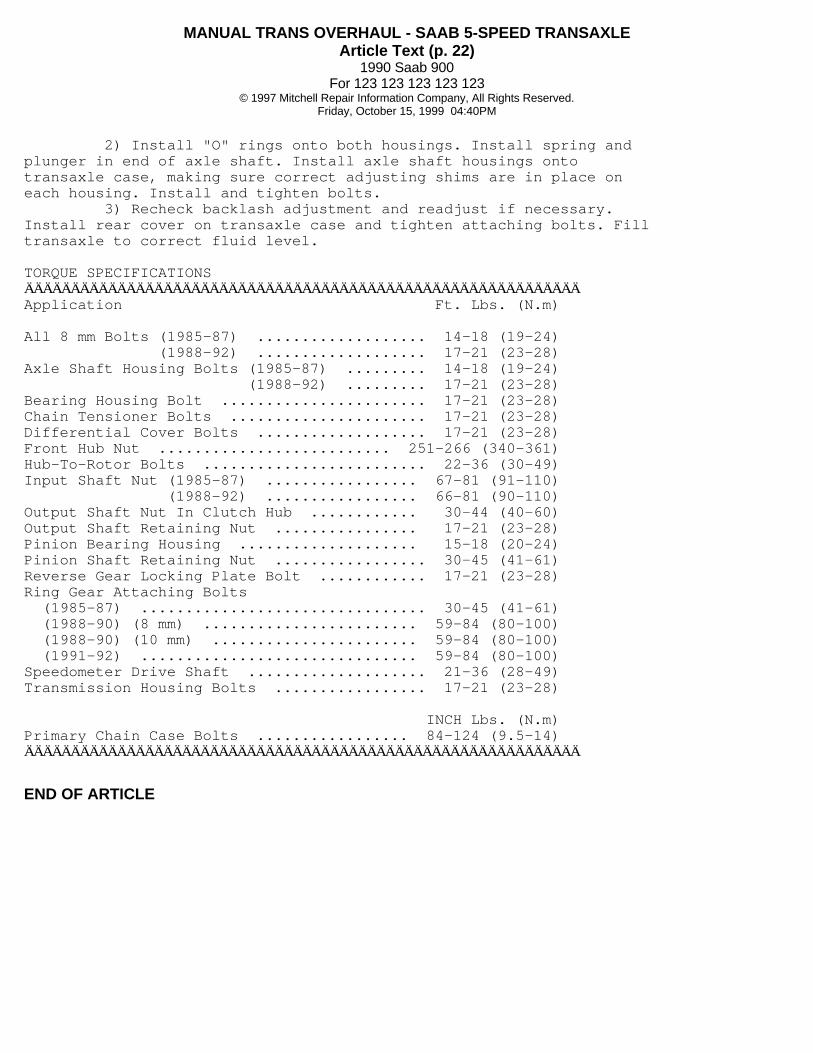
2) Install "O" rings onto both housings. Install spring andplunger in end of axle shaft. Install axle shaft housings ontotransaxle case, making sure correct adjusting shims are in place oneach housing. Install and tighten bolts. 3) Recheck backlash adjustment and readjust if necessary.Install rear cover on transaxle case and tighten attaching bolts. Filltransaxle to correct fluid level.
TORQUE SPECIFICATIONSÄÄÄÄÄÄÄÄÄÄÄÄÄÄÄÄÄÄÄÄÄÄÄÄÄÄÄÄÄÄÄÄÄÄÄÄÄÄÄÄÄÄÄÄÄÄÄÄÄÄÄÄÄÄÄÄÄÄÄÄApplication Ft. Lbs. (N.m)
All 8 mm Bolts (1985-87) ................... 14-18 (19-24) (1988-92) ................... 17-21 (23-28)Axle Shaft Housing Bolts (1985-87) ......... 14-18 (19-24) (1988-92) ......... 17-21 (23-28)Bearing Housing Bolt ....................... 17-21 (23-28)Chain Tensioner Bolts ...................... 17-21 (23-28)Differential Cover Bolts ................... 17-21 (23-28)Front Hub Nut .......................... 251-266 (340-361)Hub-To-Rotor Bolts ......................... 22-36 (30-49)Input Shaft Nut (1985-87) ................. 67-81 (91-110) (1988-92) ................. 66-81 (90-110)Output Shaft Nut In Clutch Hub ............ 30-44 (40-60)Output Shaft Retaining Nut ................ 17-21 (23-28)Pinion Bearing Housing .................... 15-18 (20-24)Pinion Shaft Retaining Nut ................. 30-45 (41-61)Reverse Gear Locking Plate Bolt ............ 17-21 (23-28)Ring Gear Attaching Bolts (1985-87) ................................ 30-45 (41-61) (1988-90) (8 mm) ........................ 59-84 (80-100) (1988-90) (10 mm) ....................... 59-84 (80-100) (1991-92) ............................... 59-84 (80-100)Speedometer Drive Shaft .................... 21-36 (28-49)Transmission Housing Bolts ................. 17-21 (23-28)
INCH Lbs. (N.m)Primary Chain Case Bolts ................. 84-124 (9.5-14)ÄÄÄÄÄÄÄÄÄÄÄÄÄÄÄÄÄÄÄÄÄÄÄÄÄÄÄÄÄÄÄÄÄÄÄÄÄÄÄÄÄÄÄÄÄÄÄÄÄÄÄÄÄÄÄÄÄÄÄÄ
END OF ARTICLE