group 22b manual transaxle overhaul tearstone.com/eclipsefsm/2006_ps24s_mmna_sm_pdf… · ·...
TRANSCRIPT

22B-1
GROUP 22B
MANUAL TRANSAXLE OVERHAUL
<F5M42>CONTENTS
GENERAL DESCRIPTION. . . . . . . . . 22B-2
SPECIAL TOOLS. . . . . . . . . . . . . . . . 22B-3
TRANSAXLE . . . . . . . . . . . . . . . . . . . 22B-6DISASSEMBLY AND ASSEMBLY . . . . . . . 22B-6INSPECTION . . . . . . . . . . . . . . . . . . . . . . . 22B-15
INPUT SHAFT . . . . . . . . . . . . . . . . . . 22B-16DISASSEMBLY AND ASSEMBLY . . . . . . . 22B-16INSPECTION . . . . . . . . . . . . . . . . . . . . . . . 22B-22
OUTPUT SHAFT . . . . . . . . . . . . . . . . 22B-24DISASSEMBLY AND ASSEMBLY . . . . . . . 22B-24INSPECTION . . . . . . . . . . . . . . . . . . . . . . . 22B-32
REVERSE IDLER GEAR . . . . . . . . . . 22B-35DISASSEMBLY AND ASSEMBLY . . . . . . . 22B-35
VEHICLE SPEED SENSOR. . . . . . . . 22B-36DISASSEMBLY AND ASSEMBLY . . . . . . . 22B-36
SELECT LEVER . . . . . . . . . . . . . . . . . 22B-37DISASSEMBLY AND ASSEMBLY . . . . . . . 22B-37
CONTROL HOUSING. . . . . . . . . . . . . 22B-39DISASSEMBLY AND ASSEMBLY . . . . . . . 22B-39
CLUTCH HOUSING . . . . . . . . . . . . . . 22B-42DISASSEMBLY AND ASSEMBLY . . . . . . . 22B-42
TRANSMISSION CASE . . . . . . . . . . . 22B-46DISASSEMBLY AND ASSEMBLY . . . . . . . 22B-46
DIFFERENTIAL. . . . . . . . . . . . . . . . . . 22B-48DISASSEMBLY AND ASSEMBLY . . . . . . . 22B-48
SPECIFICATIONS . . . . . . . . . . . . . . . 22B-51FASTENER TIGHTENING SPECIFICATIONS. . . . . . . . . . . . . . . . . . . . 22B-51GENERAL SPECIFICATIONS . . . . . . . . . . 22B-51SERVICE SPECIFICATIONS . . . . . . . . . . . 22B-52SEALANTS AND ADHESIVES . . . . . . . . . . 22B-52LUBRICANTS . . . . . . . . . . . . . . . . . . . . . . . 22B-52SNAP RINGS, SPACERS AND THRUST PLATE FOR ADJUSTMENT . . . . . . . . . . . . 22B-53

GENERAL DESCRIPTIONMANUAL TRANSAXLE OVERHAUL <F5M42>22B-2
GENERAL DESCRIPTIONM1222000100283
SECTIONAL VIEW
AK302357
TSB Revision

SPECIAL TOOLSMANUAL TRANSAXLE OVERHAUL <F5M42> 22B-3
SPECIAL TOOLSM1222000600307
TOOL TOOL NUMBER AND NAME
SUPERSESSION APPLICATION
MB990935Installer adapter
MB990935-01 or General service tool
Installation of differential case taper roller bearing outer race
MB990938Handle
MB990938-01 Use with Installer adapter
MB990927Installer adapter
MB990927-01 or General service tool
Installation of sealing cap
MD998801Bearing remover
MD998348-01 or General service tool
Installation and removal of gears, bearings and sleeves
MD998812Installer cap
General service tool Use with Installer and Installer adapter
MD998813Installer-100
General service tool Use with Installer cap and Installer adapter
MD998816Installer adapter (30)
General service tool Installation of input shaft front bearing
MD998825Installer adapter (52)
General service tool Installation of 1st-2nd speed synchronizer hub, 3rd-4th speed synchronizer hub and 1st speed gear sleeve
TSB Revision

SPECIAL TOOLSMANUAL TRANSAXLE OVERHAUL <F5M42>22B-4
MD998824Installer adapter (50)
MD998824-01 Installation of 4th speed gear sleeve and 5th speed gear
MD998818Installer adapter (38)
MD998818 or General service tool
Installation of input shaft rear bearing, roller bearing inner race, reverse gear sleeve and output shaft rear ball bearing
MD998917Bearing remover
General service tool Installation and removal of gears, bearing and sleeves
MD998814Installer-200
MIT304180-A Use with Installer cap and Installer adapter
MD998822Installer adapter (46)
MD998822-01 Installation of 2nd speed gear sleeve and 3rd speed gear
MD998819Installer adapter (40)
General service tool Installation of 5th-reverse speed synchronizer hub, differential case bearing, 4th speed gear and 5th speed gear sleeve
MD999566Claw
General service tool Removal of taper roller bearing outer race
MD998772Valve spring compressor
General service tool Removal of output shaft front roller bearing outer race
TOOL TOOL NUMBER AND NAME
SUPERSESSION APPLICATION
TSB Revision

SPECIAL TOOLSMANUAL TRANSAXLE OVERHAUL <F5M42> 22B-5
MD998346Bearing outer race remover
MD998346-01 or General service tool
Removal of output shaft front roller bearing outer race
MB990934Installer adapter
MB990934-01 or General service tool
Installation of output shaft front roller bearing outer race
MD998325Differential oil seal installer
MD998325-01 Installation of differential oil seal
MB990926Installer adapter
MB990926-01 or General service tool
Installation of clutch housing input shaft oil seal
TOOL TOOL NUMBER AND NAME
SUPERSESSION APPLICATION
TSB Revision
TRANSAXLEMANUAL TRANSAXLE OVERHAUL <F5M42>22B-6
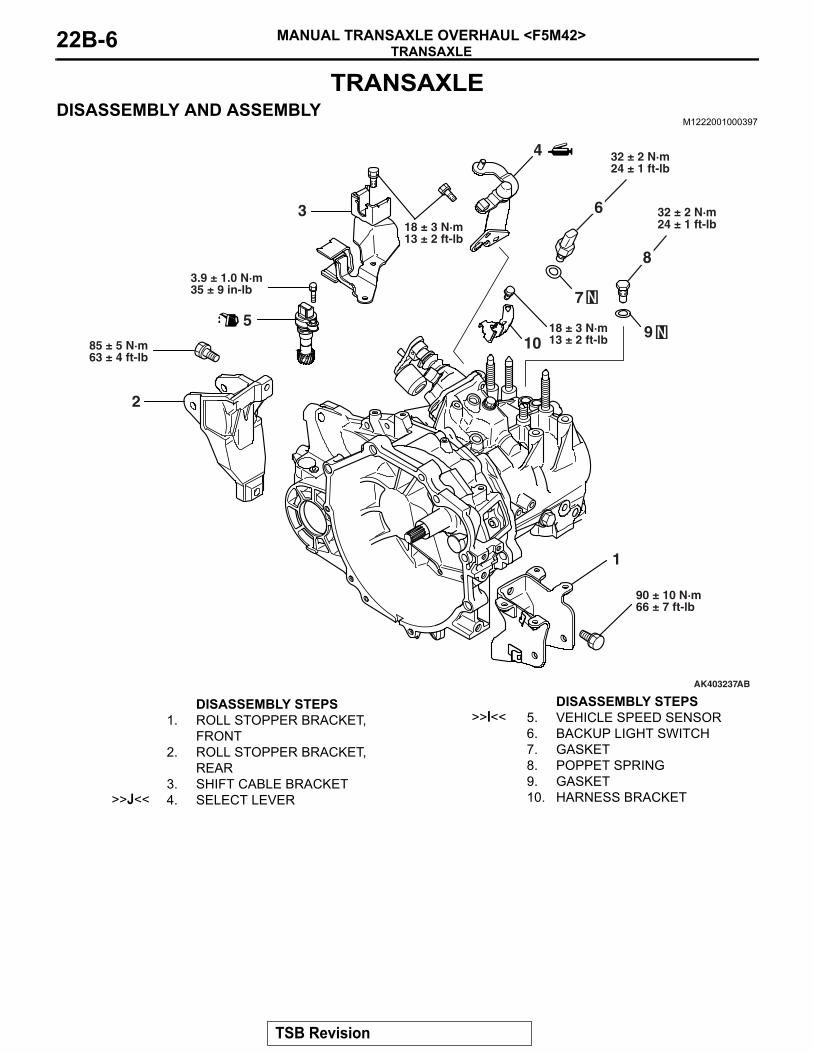
TRANSAXLEDISASSEMBLY AND ASSEMBLY
M1222001000397
AK403237
32 ± 2 N·m24 ± 1 ft-lb
83.9 ± 1.0 N·m35 ± 9 in-lb
85 ± 5 N·m63 ± 4 ft-lb
4
3
9
75
2
1
AB
90 ± 10 N·m66 ± 7 ft-lb
18 ± 3 N·m13 ± 2 ft-lb
18 ± 3 N·m13 ± 2 ft-lb10
32 ± 2 N·m24 ± 1 ft-lb
6
DISASSEMBLY STEPS 1. ROLL STOPPER BRACKET,
FRONT2. ROLL STOPPER BRACKET,
REAR3. SHIFT CABLE BRACKET
>>J<< 4. SELECT LEVER
>>I<< 5. VEHICLE SPEED SENSOR6. BACKUP LIGHT SWITCH7. GASKET8. POPPET SPRING9. GASKET10. HARNESS BRACKET
DISASSEMBLY STEPS
TSB Revision

TRANSAXLEMANUAL TRANSAXLE OVERHAUL <F5M42> 22B-7
AK403238
18 ± 3 N·m13 ± 2 ft-lb
44 ± 5 N·m32 ± 4 ft-lb
6.9 ± 0.9 N·m61 ± 8 in-lb
13
1412
2221
1823
24
15
AB
APPLY GEAR OILTO ALL MOVINGPARTS BEFOREINSTALLATION.
30 ± 3 N·m22 ± 2 ft-lb
11
19
48 ± 6 N·m35 ± 4 ft-lb
16
17
20
DISASSEMBLY STEPS 11. INTERLOCK PLATE BOLT12. GASKET
>>H<< 13. CONTROL HOUSING14. NEUTRAL RETURN SPRING
>>G<< 15. UNDER COVER16. REVERSE IDLER GEAR SHAFT
BOLT17. GASKET
18. REVERSE IDLER GEAR ASSEMBLY
<<A>> >>F<< 19. SEALING CAP<<B>> >>E<< 20. TRANSAXLE CASE
>>D<< 21. OUTER RACE>>D<< 22. SPACER
23. MAGNET HOLDER24. MAGNET
DISASSEMBLY STEPS
TSB Revision

TRANSAXLEMANUAL TRANSAXLE OVERHAUL <F5M42>22B-8
AK402413
34
AB
26
31
3332
36
35
18 ± 3 N·m13 ± 2 ft-lb
2737
38
30
25
28 29APPLY GEAR OILTO ALL MOVINGPARTS BEFOREINSTALLATION.
DISASSEMBLY STEPS >>C<< 25. SPRING PIN
26. 1ST-2ND SPEED SHIFT RAIL27. 1ST-2ND SPEED SHIFT FORK
>>C<< 28. SPRING PIN>>C<< 29. SPRING PIN
<<C>> >>B<< 30. 3RD-4TH SPEED SHIFT RAIL<<C>> >>B<< 31. 3RD-4TH SPEED SHIFT FORK<<C>> >>B<< 32. 5TH SPEED-REVERSE SHIFT
RAIL
<<C>> >>B<< 33. 5TH SPEED-REVERSE SHIFT FORK
34. FRONT BEARING RETAINER<<D>> >>A<< 35. INPUT SHAFT<<D>> >>A<< 36. OUTPUT SHAFT
37. DIFFERENTIAL38. CLUTCH HOUSING
Required Special Tools:• MB990927: Installer Adapter • MB990935: Installer Adapter
• MB990938: Handle
DISASSEMBLY STEPS
TSB Revision

TRANSAXLEMANUAL TRANSAXLE OVERHAUL <F5M42> 22B-9
DISASSEMBLY SERVICE POINTS.
<<A>> SEALING CAP REMOVAL
AK305183
1. Drive a screwdriver into the center of the sealing cap.2. Use the screwdriver back to pry off the sealing cap.
.
<<B>> TRANSAXLE CASE REMOVAL
AK305108
1. Remove all sixteen bolts securing the transaxle case to the clutch housing.
2. Use snap ring pliers to expand the indicated snap ring. The snap ring will release the grooved ball bearing, and the output shaft assembly will fall under its own weight.CAUTION
Do not use a scraper or chisel to remove the transaxle case.3. Remove the transaxle case from the clutch housing by
gently prying on opposite sides at the same time. .
<<C>> 3RD-4TH SPEED SHIFT RAIL/3RD-4TH SPEED SHIFT FORK/5TH SPEED-REVERSE SHIFT RAIL/5TH SPEED-REVERSE SHIFT FORK REMOVAL
AK400310
3RD-4TH SPEEDSHIFT FORK
AB
5TH SPEED REVERSESHIFT FORK
1. Shift the 3rd-4th speed shift fork and 5th speed-reverse shift fork in the direction shown.
AK400311
3RD-4TH SPEEDSHIFT RAIL
AB
5TH SPEED-REVERSESHIFT FORK
2. Pull up on the 3rd-4th speed shift rail and 5th speed-reverse shift rail and take them out of the hole in the clutch housing.
3. Slide the 3rd-4th speed shift rail and 5th speed-reverse shift rail in the direction shown and remove them together with the shift forks.
.
TSB Revision

TRANSAXLEMANUAL TRANSAXLE OVERHAUL <F5M42>22B-10
<<D>> INPUT SHAFT AND OUTPUT SHAFT REMOVAL
AK400312
INPUT SHAFT
OUTPUT SHAFT
AB
Remove the input and output shafts together.
ADJUSTMENT BEFORE ASSEMBLYSPACER SELECTION FOR DIFFERENTIAL CASE PRE-LOAD ADJUSTMENT.
<Measurement using a Solder>
AK400313
SOLDERS
AB
AK305233
1. Put solders [1.0 mm (0.039 inch) diameter, about 10 mm (0.39 inch) long] in the illustrated positions of the transaxle case.
2. Install the taper bearing outer race and differential assembly into the transaxle case. NOTE: If necessary, replace the differential case and taper bearing before carrying out these adjustments.
3. Install the clutch housing and tighten the bolts to the specified torque.
Tightening torque: 44 ± 5 N⋅ m (32 ± 4 ft-lb)4. Remove the clutch housing, and then remove the differential
assembly.5. Remove the taper bearing outer race and take out crushed
solders.6. If the solders have not crushed, use thicker solders [1.6 mm
(0.063 inch) diameter, about 10 mm (0.39 inch) long] and repeat steps 2 to 5.
7. Measure the thickness of the crushed solder with a micrometer and select a spacer that will provide the standard preload value.
Standard value: 0.05 − 0.11 mm (0.0020 − 0.0043 inch) preload
.
TSB Revision

TRANSAXLEMANUAL TRANSAXLE OVERHAUL <F5M42> 22B-11
<Measurement using Plastigage>
AK400313AE
PLASTIGAGE
1. Put plastigage [about 10 mm (0.39 inch) long] in the illustrated positions of the transaxle case.
2. Install the thinnest spacer.3. Install the taper bearing outer race and differential assembly
into the transaxle case. NOTE: If necessary, replace the differential case and taper bearing before carrying out these adjustments.
4. Install the clutch housing and tighten the bolts to the specified torque.
Tightening torque: 44 ± 5 N⋅ m (32 ± 4 ft-lb)5. Remove the clutch housing, and then remove the differential
assembly.6. Remove taper bearing outer race and the spacer.7. If the Plastigages have not crushed, replace the spacer with
a thicker one and repeat steps 2 to 7.
AK402081
PLASTIGAGE
SPACER AC
8. Measure the width of the crushed Plastigage at its widest part using a scale printed on the Plastigage package.
Standard value: 0.05 − 0.11 mm (0.0020 − 0.0043 inch) preload
ASSEMBLY SERVICE POINTS.
>>A<< OUTPUT SHAFT/INPUT SHAFT INSTALLA-TION
AK400312
INPUT SHAFT
OUTPUT SHAFT
AB
Install the input and output shafts together.
.
TSB Revision

TRANSAXLEMANUAL TRANSAXLE OVERHAUL <F5M42>22B-12
>>B<< 5TH SPEED-REVERSE SHIFT FORK/5TH SPEED-REVERSE SHIFT RAIL/3RD-4TH SPEED SHIFT FORK/3RD-4TH SPEED SHIFT RAIL INSTALLATION
AK400315
3RD-4TH SPEEDSYNCHRENIZERSLEEVE
5TH SPEED-REVERSESYNCHRONIZERSLEEVE
AB
1. Shift the 3rd-4th speed synchronizer sleeve and 5th speed-reverse synchronizer sleeve in the direction shown.
AK400316
3RD-4TH SPEEDSHIFT RAIL
3RD-4TH SPEEDSHIFT FORK
5THSPEED-REVERSESHIFT RAIL
5TH SPEED-REVERSESHIFT FORK AB
2. Assemble the 3rd-4th speed shift rail and fork, and the 5th speed-reverse shift rail and fork.
AK400311
3RD-4TH SPEEDSHIFT RAIL
AC
5TH SPEED-REVERSESHIFT FORK
3. While fitting each shift fork in the groove of synchronizer sleeve, slide the shift rails in the direction shown and install.
4. Insert the 3rd-4th speed shift rail and 5th speed-reverse shift rail into the rail hole in the clutch housing.
.
>>C<< SPRING PIN INSTALLATION
AKX00920
SHIFT FORK2.5 mm (0.098 in)SHIFT RAIL
SPRINGPIN
AB
1. Align the pin holes in the shift rail and shift fork.2. Insert the new spring pin. Push it in as shown so that the slit
and center axis of the rail are aligned.
.
TSB Revision

TRANSAXLEMANUAL TRANSAXLE OVERHAUL <F5M42> 22B-13
>>D<< SPACER AND OUTER RACE INSTALLATION1. Install the spacer selected in the section "ADJUSTMENT
BEFORE ASSEMBLY."
AK305113AC
MB990938
MB990935
2. Using special tools MB990935 and MB990938, press the outer race into the transaxle case.
.
>>E<< TRANSAXLE CASE INSTALLATION
AKX00816
CAUTIONSqueeze sealant evenly onto the transaxle housing. Do not leave gaps or excess amounts, otherwise oil leaks are likely. 1. Apply a 1.5 mm (0.06 inch) diameter bead of sealant
(Mitsubishi Part number MD997740 or equivalent) as illustrated onto the transaxle case.NOTE: Be sure to install the transaxle case onto the tran-saxle housing while the sealant is still wet (within 15 min-utes).
AK305108
2. Align the transaxle case and expand the snap ring. After the case is on far enough for the snap ring to ride on the bearing, release the snap ring. Push down on the transaxle case, twisting it from side to side until the case contacts the housing.
3. Tighten the transaxle case mounting bolts to the specified torque.
Tightening torque: 44 ± 5 N⋅ m (32 ± 4 ft-lb)4. Place the transaxle upside down and let the snap ring fit in
the groove by the output shaft's own weight.NOTE: After installation, keep the sealed area away from oil for approximately one hour.
.
TSB Revision
TRANSAXLEMANUAL TRANSAXLE OVERHAUL <F5M42>22B-14
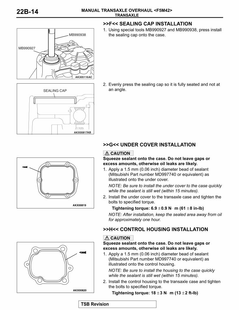
>>F<< SEALING CAP INSTALLATION
AK305116AC
MB990938
MB990927
1. Using special tools MB990927 and MB990938, press install the sealing cap onto the case.
AKX00817
SEALING CAP
AB
2. Evenly press the sealing cap so it is fully seated and not at an angle.
.
>>G<< UNDER COVER INSTALLATION
AKX00819
CAUTIONSqueeze sealant onto the case. Do not leave gaps or excess amounts, otherwise oil leaks are likely. 1. Apply a 1.5 mm (0.06 inch) diameter bead of sealant
(Mitsubishi Part number MD997740 or equivalent) as illustrated onto the under cover.NOTE: Be sure to install the under cover to the case quickly while the sealant is still wet (within 15 minutes).
2. Install the under cover to the transaxle case and tighten the bolts to specified torque.
Tightening torque: 6.9 ± 0.9 N⋅ m (61 ± 8 in-lb)NOTE: After installation, keep the sealed area away from oil for approximately one hour.
.
>>H<< CONTROL HOUSING INSTALLATION
AKX00820
CAUTIONSqueeze sealant onto the case. Do not leave gaps or excess amounts, otherwise oil leaks are likely. 1. Apply a 1.5 mm (0.06 inch) diameter bead of sealant
(Mitsubishi Part number MD997740 or equivalent) as illustrated onto the control housing.NOTE: Be sure to install the housing to the case quickly while the sealant is still wet (within 15 minutes).
2. Install the control housing to the transaxle case and tighten the bolts to specified torque.
Tightening torque: 18 ± 3 N⋅ m (13 ± 2 ft-lb)
TSB Revision

TRANSAXLEMANUAL TRANSAXLE OVERHAUL <F5M42> 22B-15
NOTE: After installation, keep the sealed area away from the oil for approximately one hour.
.
>>I<< VEHICLE SPEED SENSOR INSTALLATION
AKX00821
O-RING
AB
1. Apply gear oil (Hypoid gear oil SAE 75W-90 or 75W-85W conforming to API classification GL-4) to the O-ring of the vehicle speed sensor. Install into the transaxle housing.
2. Tighten the bolt to specified torque.Tightening torque: 3.9 ± 1.0 N⋅ m (35 ± 9 in-lb)
.
>>J<< SELECT LEVER INSTALLATION
AKX00822
CONTROL SHAFT
SELECTLEVERSHOE
AB
1. Apply grease (Mitsubishi Part number 0101011 or equivalent) to the control shaft sliding portion of the select lever shoe.
2. Install the select lever and tighten the bolts to specified torque.
Tightening torque: 18 ± 3 N⋅ m (13 ± 2 ft-lb)
INSPECTIONM1222001100220
.
BACKUP LIGHT SWITCH
AK201630
Check for continuity between terminals.
SWITCH CONDITION CONTINUITYPressed Open
Released Conductive
TSB Revision

INPUT SHAFTMANUAL TRANSAXLE OVERHAUL <F5M42>22B-16
INPUT SHAFTDISASSEMBLY AND ASSEMBLY
M1222001600344
AKX00803
APPLY GEAR OILTO ALL MOVINGPARTS BEFOREINSTALLATION.
910
11
1214
1315
16
18 219
420 6
71
83
17 16
5AB
DISASSEMBLY STEPS >>M<< 1. SNAP RING
<<A>> >>L<< 2. BALL BEARING<<B>> >>K<< 3. THRUST PLATE STOPPER
>>J<< 4. THRUST PLATE<<C>> >>I<< 5. 5TH SPEED GEAR
6. 4TH SPEED GEAR7. NEEDLE ROLLER BEARING
<<D>> >>H<< 8. 4TH SPEED GEAR SLEEVE>>E<< 9. SYNCHRONIZER RING>>D<< 10. SYNCHRONIZER SPRING>>G<< 11. SYNCHRONIZER SLEEVE
>>F<< 12. 3RD-4TH SPEED SYNCHRONIZER HUB
>>E<< 13. SYNCHRONIZER RING>>D<< 14. SYNCHRONIZER SPRING
15. 3RD SPEED GEAR16. NEEDLE ROLLER BEARING
>>C<< 17. SNAP RING<<E>> >>B<< 18. BALL BEARING
>>A<< 19. OIL SEAL20. INPUT SHAFT
Required Special Tools:• MD998801: Bearing Remover• MD998812: Installer Cap• MD998813: Installer-100• MD998816: Installer Adapter (30)
• MD998818: Installer Adapter (38)• MD998824: Installer Adapter (50) • MD998825: Installer Adapter (52)
DISASSEMBLY STEPS
TSB Revision

INPUT SHAFTMANUAL TRANSAXLE OVERHAUL <F5M42> 22B-17
DISASSEMBLY SERVICE POINTS.
<<A>> BALL BEARING REMOVAL
AK400317AB
MD998801
1. Using special tool MD998801, support the ball bearing, and then set them on the press.
2. Push down on the input shaft with the press and remove the ball bearing.
.
<<B>> THRUST PLATE STOPPER REMOVAL
AK400318AB
Using a screwdriver, pry up at the position shown in the illustra-tion and remove the thrust plate stopper.
.
<<C>>5TH SPEED GEAR REMOVAL
AK400319
MD998801
AB
1. Using special tool MD998801, support the 5th speed gear, and then set them on the press.
2. Push down on the input shaft with the press and remove the 5th speed gear.
.
<<D>>4TH SPEED GEAR SLEEVE REMOVAL
AK400320
MD998801
AB
1. Using special tool MD998801, support the 3rd speed gear, and then set them on the press.
2. Push down on the input shaft with the press and remove the 4th speed gear sleeve.
.
TSB Revision

INPUT SHAFTMANUAL TRANSAXLE OVERHAUL <F5M42>22B-18
<<E>> BALL BEARING REMOVAL
AK400321
MD998801
AB
1. Using special tool MD998801, support the ball bearing, and then set them on the press.
2. Push down on the input shaft with the press and remove the ball bearing.
ASSEMBLY SERVICE POINTS.
>>A<< OIL SEAL INSTALLATION
AKX00827
3.5 mm (0.138 in)
OIL SEAL
AB
Install the oil seal into the end of the input shaft as shown.
.
>>B<< BALL BEARING INSTALLATION
AK400322
MD998812
MD998813
MD998816MD998801
AB
1. Using special tool MD998801, support the 2nd speed gear portion of the input shaft, and then set them on the press.
2. Using special tools MD998812, MD998813 and MD998816, press install the bearing with the press.
.
>>C<< SNAP RING INSTALLATION
AK400323AB
SNAP RING
1. Install the thickest snap ring that can be fitted in the snap ring groove of input shaft.
2. Make sure that the ball bearing end play meets the standard value.
Standard value: 0 − 0.12 mm (0 − 0.0047 inch)
.
TSB Revision

INPUT SHAFTMANUAL TRANSAXLE OVERHAUL <F5M42> 22B-19
>>D<< SYNCHRONIZER SPRING INSTALLATION
AKX00847
SYNCHRONIZERSPRING AB
Install the synchronizer spring onto the synchronizer ring as shown.
.
>>E<< SYNCHRONIZER RING INSTALLATION
AKX00941
NOTCH
AB
CAUTIONThere are 3rd speed and 4th speed synchronizer rings, if the wrong one is installed it will affect the shift feeling.1. Determine whether or not there are identification notches on
the synchronizer ring.Two notches: 3rd speed synchronizer ringNo notches: 4th speed synchronizer ring
2. Install the synchronizer ring so that it completely fits over the machined cone of the gear.
.
>>F<< 3RD-4TH SPEED SYNCHRONIZER HUB INSTALLATION
AKX00913
INSTALLATIONDIRECTION
GROOVE AB
1. Using special tool MD998801, support the 2nd speed gear portion of the input shaft, and then set them on the press.
2. Make sure that the synchronizer ring has been perfectly matched to the 3rd speed gear cone.
3. Check the installation direction of the 3rd-4th speed synchronizer hub, and put it on the input shaft.
AK400324
MD998812
MD998813
MD998825MD998801
AB
4. Using special tools MD998812, MD998813 and MD998825, press install the 3rd-4th speed synchronizer hub with the press.
5. Make sure that the synchronizer ring can rotate freely.
.
TSB Revision

INPUT SHAFTMANUAL TRANSAXLE OVERHAUL <F5M42>22B-20
>>G<< SYNCHRONIZER SLEEVE INSTALLATION
AK400082
INSTALLATIONDIRECTION(3RD SPEED SIDE)
IDENTIFICATIONGROOVE
AC
1. Check the installation direction of the synchronizer sleeve, and install it onto the 3rd-4th speed synchronizer hub.
AKX00928AB
TEETH WITHRAISED TIPS
DEEP GROOVES BETWEEN THE TEETH
2. Install the synchronizer sleeve so that the areas with teeth that have raised tips (three areas total) are aligned with the areas on the synchronizer hub that have deep grooves between the teeth (three areas total).
.
>>H<< 4TH SPEED GEAR SLEEVE INSTALLATION
AK400325
MD998812
MD998813
MD998824MD998801
AB
1. Using special tool MD998801, support the 2nd speed gear portion of the input shaft, and then set them on the press.
2. Using special tools MD998812, MD998813 and MD998824, install the 4th speed gear sleeve with the press.
.
>>I<< 5TH SPEED GEAR INSTALLATION
AK400326
MD998801
MD998812
MD998813
MD998824
AB
1. Using special tool MD998801, support the 2nd speed gear portion of the input shaft, and then set them on the press.
2. Using special tools MD998812, MD998813 and MD998824, install the 5th speed gear onto the input shaft with the press.
.
TSB Revision

INPUT SHAFTMANUAL TRANSAXLE OVERHAUL <F5M42> 22B-21
>>J<< THRUST PLATE INSTALLATION
AK400327
THRUST PLATE
SURFACE STAMPED WITHIDENTIFICATION MARK
AB
1. Install the thickest thrust plates that can be fitted in the groove of the input shaft. Install the thrust plate so the surface stamped with the identification mark is facing up.
2. Make sure that the 5th speed gear end play meets the standard value.
Standard value: 0 − 0.09 mm (0 − 0.0035 inch)
.
>>K<< THRUST PLATE STOPPER INSTALLATION
AK400328
MD998812
MD998813
MD998824
AB
Install the thrust plate stopper by pressing special tools MD998812, MD998813 and MD998824 by hand. Make sure that it is not tilted.
.
>>L<< BALL BEARING INSTALLATION
AK400329
MD998812
MD998818
MD998801
AB
1. Using special tool MD998801, support the 2nd speed gear portion of the input shaft, and then set them on the press.
2. Using special tools MD998812 and MD998818, install the ball bearing onto the input shaft with the press.
.
>>M<< SNAP RING INSTALLATION
AK400330
SNAP RING
AB
1. Install the thickest snap ring that can be fitted in the groove of the input shaft.
2. Make sure that the ball bearing end play meets the standard value.
Standard value: 0 − 0.12 mm (0 − 0.0047 inch)
TSB Revision
INPUT SHAFTMANUAL TRANSAXLE OVERHAUL <F5M42>22B-22
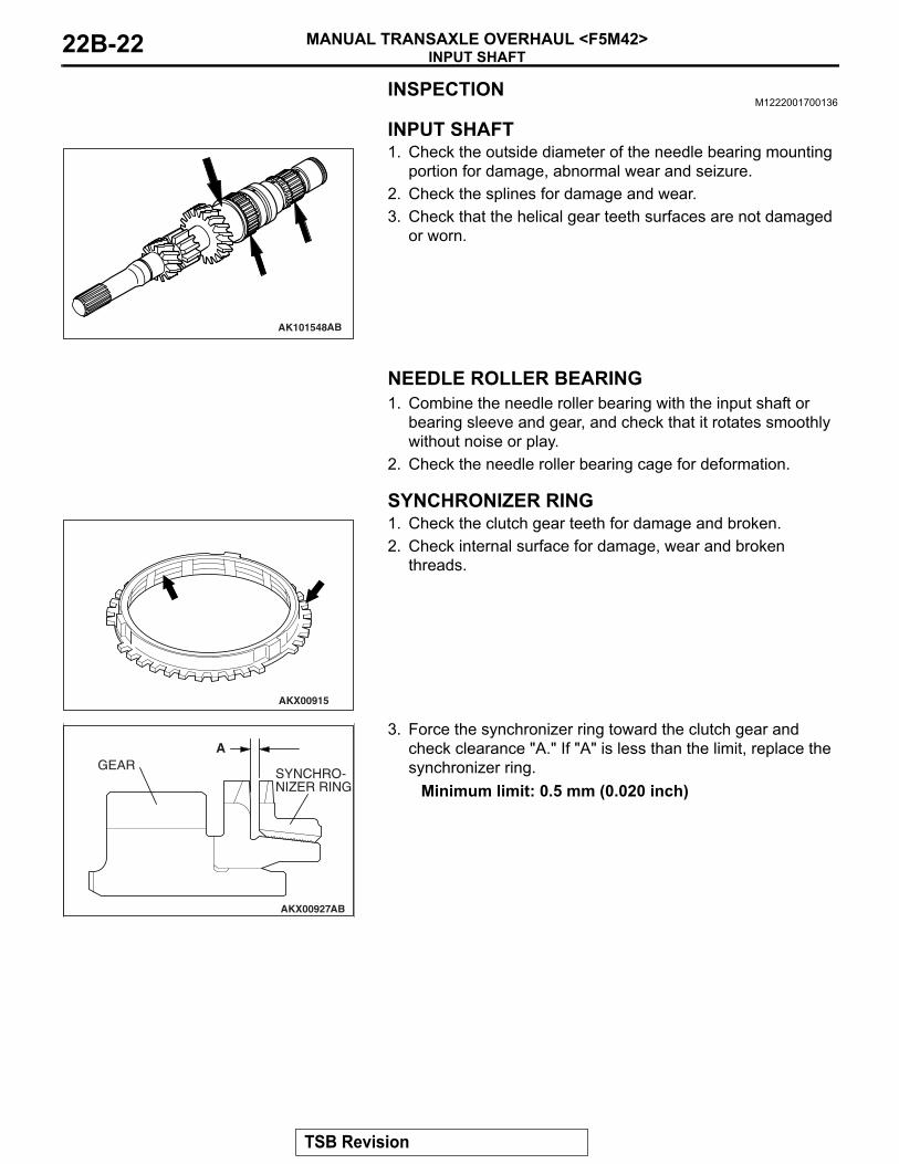
INSPECTIONM1222001700136
.
INPUT SHAFT
AK101548AB
1. Check the outside diameter of the needle bearing mounting portion for damage, abnormal wear and seizure.
2. Check the splines for damage and wear.3. Check that the helical gear teeth surfaces are not damaged
or worn.
.
NEEDLE ROLLER BEARING1. Combine the needle roller bearing with the input shaft or
bearing sleeve and gear, and check that it rotates smoothly without noise or play.
2. Check the needle roller bearing cage for deformation..
SYNCHRONIZER RING
AKX00915
1. Check the clutch gear teeth for damage and broken.2. Check internal surface for damage, wear and broken
threads.
AKX00927
AGEAR
SYNCHRO-NIZER RING
AB
3. Force the synchronizer ring toward the clutch gear and check clearance "A." If "A" is less than the limit, replace the synchronizer ring.
Minimum limit: 0.5 mm (0.020 inch)
.
TSB Revision

INPUT SHAFTMANUAL TRANSAXLE OVERHAUL <F5M42> 22B-23
SYNCHRONIZER SLEEVE AND HUB
AKX00767
SLEEVE
HUB
AB
1. Combine the synchronizer sleeve and hub, and check that they slide smoothly.
2. Check that the sleeve is free from damage at its inside splines ends.
.
SYNCHRONIZER SPRINGCheck that the spring is not sagging, deformed or broken..
SPEED GEARS
AKX00916
1. Check that the helical and clutch gear tooth surfaces are not damaged or worn.
2. Check that the synchronizer cone surfaces are not roughened, damaged or worn.
3. Check that the gear inside diameter and front and rear surfaces are not damaged and worn.
TSB Revision

OUTPUT SHAFTMANUAL TRANSAXLE OVERHAUL <F5M42>22B-24
OUTPUT SHAFTDISASSEMBLY AND ASSEMBLY
M1222002200316
AK400360
2022
24
4
26
119
21
2313
2729
25
2830
313233
36
35
34
5
23
46
78
9111410
12
1715
16 13
18
APPLY GEAR OILTO ALL MOVINGPARTS BEFOREINSTALLATION.
AB
DISASSEMBLY STEPS >>R<< 1. SNAP RING
<<A>> >>Q<< 2. BALL BEARING<<B>> >>P<< 3. REVERSE GEAR SLEEVE
4. NEEDLE ROLLER BEARING5. REVERSE GEAR
>>M<< 6. SYNCHRONIZER RING>>L<< 7. SYNCHRONIZER SPRING>>O<< 8. SYNCHRONIZER SLEEVE
<<C>> >>N<< 9. 5TH SPEED-REVERSE SYNCHRONIZER HUB
>>M<< 10. SYNCHRONIZER RING>>L<< 11. SYNCHRONIZER SPRING
12. 5TH SPEED GEAR13. NEEDLE ROLLER BEARING
>>K<< 14. 5TH SPEED GEAR SLEEVE>>J<< 15. 4TH SPEED GEAR>>I<< 16. SNAP RING
<<D>> >>H<< 17. 3RD SPEED GEAR18. 2ND SPEED GEAR
19. NEEDLE ROLLER BEARING<<E>> >>G<< 20. 2ND SPEED GEAR SLEEVE
21. INNER SYNCHRONIZER RING22. SYNCHRONIZER CONE23. OUTER SYNCHRONIZER RING
>>D<< 24. SYNCHRONIZER SPRING>>F<< 25. SYNCHRONIZER SLEEVE>>E<< 26. 1ST-2ND SPEED
SYNCHRONIZER HUB27. OUTER SYNCHRONIZER RING
>>D<< 28. SYNCHRONIZER SPRING29. INNER SYNCHRONIZER RING30. SYNCHRONIZER CONE31. 1ST SPEED GEAR32. NEEDLE ROLLER BEARING
<<F>> >>C<< 33. 1ST SPEED GEAR SLEEVE>>B<< 34. SNAP RING
<<G>> >>A<< 35. ROLLER BEARING INNER RACE36. OUTPUT SHAFT
Required Special Tools:• MD998801: Bearing Remover• MD998812: Installer Cap• MD998813: Installer-100• MD998814: Installer-200• MD998818: Installer Adapter (38)
• MD998819: Installer Adapter (40)• MD998822: Installer Adapter (46) • MD998825: Installer Adapter (52) • MD998917: Bearing Remover
DISASSEMBLY STEPS
TSB Revision
OUTPUT SHAFTMANUAL TRANSAXLE OVERHAUL <F5M42> 22B-25
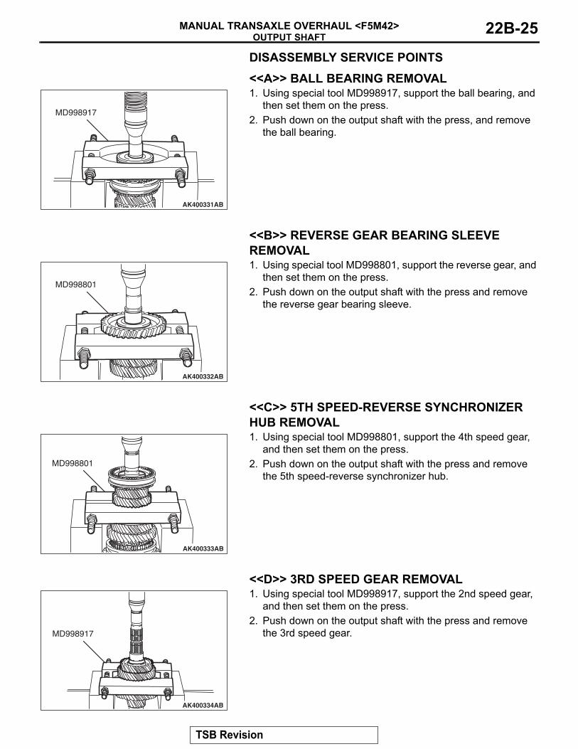
DISASSEMBLY SERVICE POINTS.
<<A>> BALL BEARING REMOVAL
AK400331
MD998917
AB
1. Using special tool MD998917, support the ball bearing, and then set them on the press.
2. Push down on the output shaft with the press, and remove the ball bearing.
.
<<B>> REVERSE GEAR BEARING SLEEVE REMOVAL
AK400332
MD998801
AB
1. Using special tool MD998801, support the reverse gear, and then set them on the press.
2. Push down on the output shaft with the press and remove the reverse gear bearing sleeve.
.
<<C>> 5TH SPEED-REVERSE SYNCHRONIZER HUB REMOVAL
AK400333
MD998801
AB
1. Using special tool MD998801, support the 4th speed gear, and then set them on the press.
2. Push down on the output shaft with the press and remove the 5th speed-reverse synchronizer hub.
.
<<D>> 3RD SPEED GEAR REMOVAL
AK400334
MD998917
AB
1. Using special tool MD998917, support the 2nd speed gear, and then set them on the press.
2. Push down on the output shaft with the press and remove the 3rd speed gear.
TSB Revision
OUTPUT SHAFTMANUAL TRANSAXLE OVERHAUL <F5M42>22B-26
.
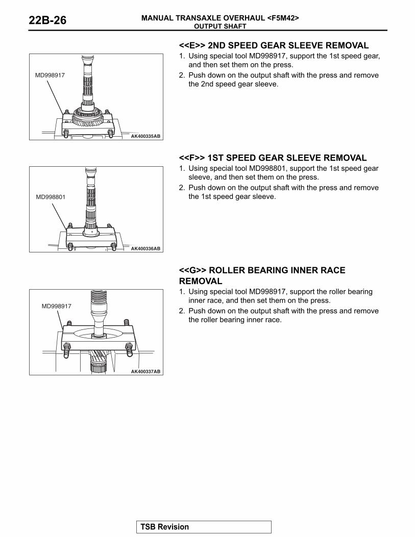
<<E>> 2ND SPEED GEAR SLEEVE REMOVAL
AK400335AB
MD998917
1. Using special tool MD998917, support the 1st speed gear, and then set them on the press.
2. Push down on the output shaft with the press and remove the 2nd speed gear sleeve.
.
<<F>> 1ST SPEED GEAR SLEEVE REMOVAL
AK400336AB
MD998801
1. Using special tool MD998801, support the 1st speed gear sleeve, and then set them on the press.
2. Push down on the output shaft with the press and remove the 1st speed gear sleeve.
.
<<G>> ROLLER BEARING INNER RACE REMOVAL
AK400337AB
MD998917
1. Using special tool MD998917, support the roller bearing inner race, and then set them on the press.
2. Push down on the output shaft with the press and remove the roller bearing inner race.
TSB Revision

OUTPUT SHAFTMANUAL TRANSAXLE OVERHAUL <F5M42> 22B-27
ASSEMBLY SERVICE POINTS.
>>A<< ROLLER BEARING INNER RACE INSTAL-LATION
AK400338AB
MD998801 MD998812
MD998818
1. Using special tool MD998801, support the output shaft gear, and then set them on the press.
2. Using special tools MD998812 and MD998818, install the roller bearing inner race with the press.
.
>>B<< SNAP RING INSTALLATION
AK400339
SNAP RING
AB
1. Install the thickest snap ring that can be fitted in the groove of output shaft.
2. Make sure that the roller bearing inner race end play meets the standard value.
Standard value: 0 − 0.12 mm (0 − 0.0047 inch)
.
>>C<<1ST SPEED GEAR SLEEVE INSTALLATION
AK400340AB
MD998812
MD998814
MD998825
1. Set the output shaft on the press support stand.2. Using special tools MD998812, MD998814 and MD998825,
install the 1st speed gear sleeve with the press.
.
>>D<< SYNCHRONIZER SPRING INSTALLATION
AKX00951
SYNCHRONIZERSPRING
AB
Install the synchronizer spring onto the outer synchronizer ringas shown.
.
TSB Revision

OUTPUT SHAFTMANUAL TRANSAXLE OVERHAUL <F5M42>22B-28
>>E<< 1ST-2ND SPEED SYNCHRONIZER HUB INSTALLATION
AKX00925
INSTALLATIONDIRECTION
AC
AK400341AB
MD998812
MD998814
MD998825
1. Set the output shaft on the press support stand.2. Check that the 1st-2nd speed synchronizer hub is in the
correct installation direction, and put it on the output shaft.3. Using special tools MD998812, MD998814 and MD998825,
install the 1st-2nd speed synchronizer hub with the press.4. Make sure that the outer synchronizer ring on the 1st speed
gear side can rotate freely.
.
>>F<< SYNCHRONIZER SLEEVE INSTALLATION
AK305817AF
INSTALLATIONDIRECTION(1ST SPEED SIDE)
IDENTIFICATION GROOVE
1. Check that the synchronizer sleeve is in the correct direction for installation, and install it on the 1st-2nd speed synchronizer hub.
AKX00928AB
TEETH WITHRAISED TIPS
DEEP GROOVES BETWEEN THE TEETH
2. Install the synchronizer sleeve so that the areas with teeth that have raised tips (three areas total) are aligned with the areas on the synchronizer hub that have deep grooves between the teeth (three areas total).
.
TSB Revision

OUTPUT SHAFTMANUAL TRANSAXLE OVERHAUL <F5M42> 22B-29
>>G<< 2ND SPEED GEAR SLEEVE INSTALLATION
AK400342AD
MD998812
MD998814
MD998822
1. Set the output shaft on the press support stand.2. Using special tools MD998812, MD998814 and MD998822,
install the 2nd speed sleeve onto the output shaft with the press.
.
>>H<< 3RD SPEED GEAR INSTALLATION
AK400343AB
MD998812
MD998814
MD998822
1. Check that the 2nd speed gear and the outer synchronizer ring have been properly installed. Also, make sure the claws on the synchronizer cone (four places) are correctly fitted into the holes in the 2nd speed gear (four places).
2. Using special tools MD998812, MD998814 and MD998822, install the 3rd speed gear onto the output shaft with thepress.
3. Make sure that the 2nd speed gear and the outer synchronizer ring can rotate freely.
.
>>I<< SNAP RING INSTALLATION
AK400344
SNAP RING
AB
1. Install the thickest snap ring that can be fitted in the groove of output shaft.
2. Make sure that the 3rd speed gear end play meets the standard value.
Standard value: 0 − 0.09 mm (0 − 0.0035 inch)
.
>>J<< 4TH SPEED GEAR INSTALLATION
AK400345AB
MD998812
MD998813
MD998819
1. Set the output shaft on the press support stand.2. Using special tools MD998812, MD998813 and MD998819,
install the 4th speed gear onto the output shaft with the press.
.
TSB Revision
OUTPUT SHAFTMANUAL TRANSAXLE OVERHAUL <F5M42>22B-30
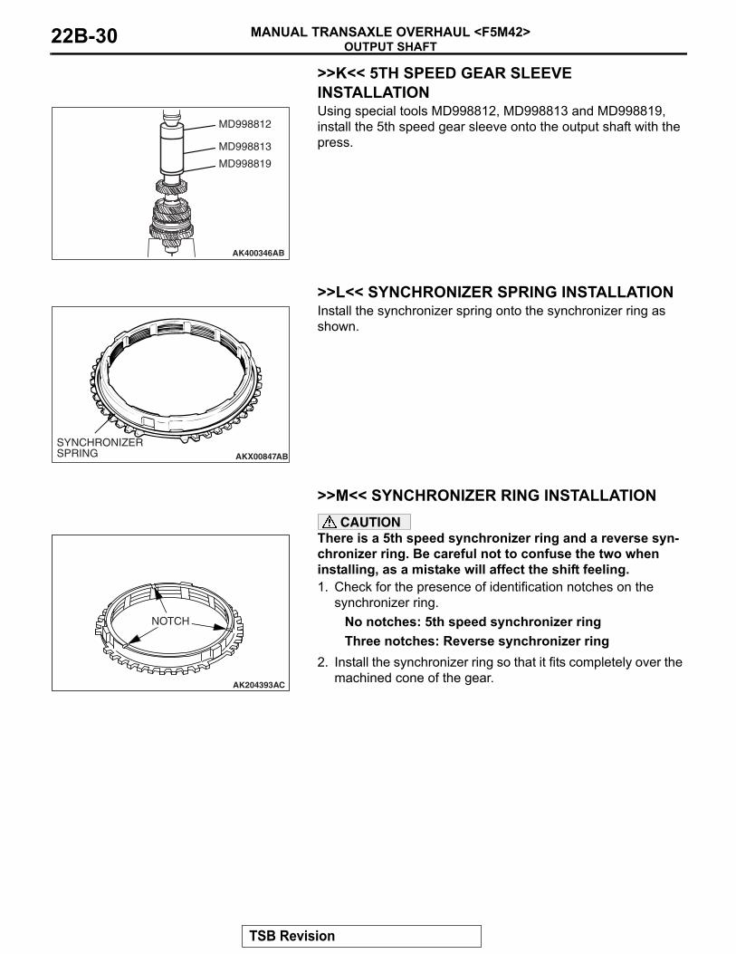
>>K<< 5TH SPEED GEAR SLEEVE INSTALLATION
AK400346AB
MD998812
MD998813
MD998819
Using special tools MD998812, MD998813 and MD998819, install the 5th speed gear sleeve onto the output shaft with the press.
.
>>L<< SYNCHRONIZER SPRING INSTALLATION
AKX00847
SYNCHRONIZERSPRING AB
Install the synchronizer spring onto the synchronizer ring as shown.
.
>>M<< SYNCHRONIZER RING INSTALLATION
AK204393
NOTCH
AC
CAUTIONThere is a 5th speed synchronizer ring and a reverse syn-chronizer ring. Be careful not to confuse the two when installing, as a mistake will affect the shift feeling.1. Check for the presence of identification notches on the
synchronizer ring.No notches: 5th speed synchronizer ringThree notches: Reverse synchronizer ring
2. Install the synchronizer ring so that it fits completely over the machined cone of the gear.
.
TSB Revision

OUTPUT SHAFTMANUAL TRANSAXLE OVERHAUL <F5M42> 22B-31
>>N<< 5TH SPEED-REVERSE SYNCHRONIZER HUB INSTALLATION
AKX00926
INSTALLATIONDIRECTION
AB
1. Set the output shaft on the press support stand.2. Make sure that the synchronizer ring is fitted correctly on the
cone of the 5th speed gear.3. Check that the 5th speed-reverse synchronizer hub is
oriented correctly for installation, and install it on the output shaft.
AK400347AB
MD998812
MD998813
MD998819
4. Using special tools MD98812, MD998813 and MD998819, press install the 5th speed-reverse synchronizer hub with the press.
5. Make sure that the synchronizer ring on the 5th speed gear side can rotate freely.
.
>>O<< SYNCHRONIZER SLEEVE INSTALLATION
AK400307
INSTALLATIONDIRECTION(5TH SPEED SIDE)
IDENTIFICATIONGROOVE
AB
1. Check that the synchronizer sleeve is in the correct direction for installation, and install it on the 5th speed-Reverse synchronizer hub.
AKX00928AB
TEETH WITHRAISED TIPS
DEEP GROOVES BETWEEN THE TEETH
2. Install the synchronizer sleeve so that the areas with teeth that have raised tips (three areas total) are aligned with the areas on the synchronizer hub that have deep grooves between the teeth (three areas total).
.
TSB Revision
OUTPUT SHAFTMANUAL TRANSAXLE OVERHAUL <F5M42>22B-32
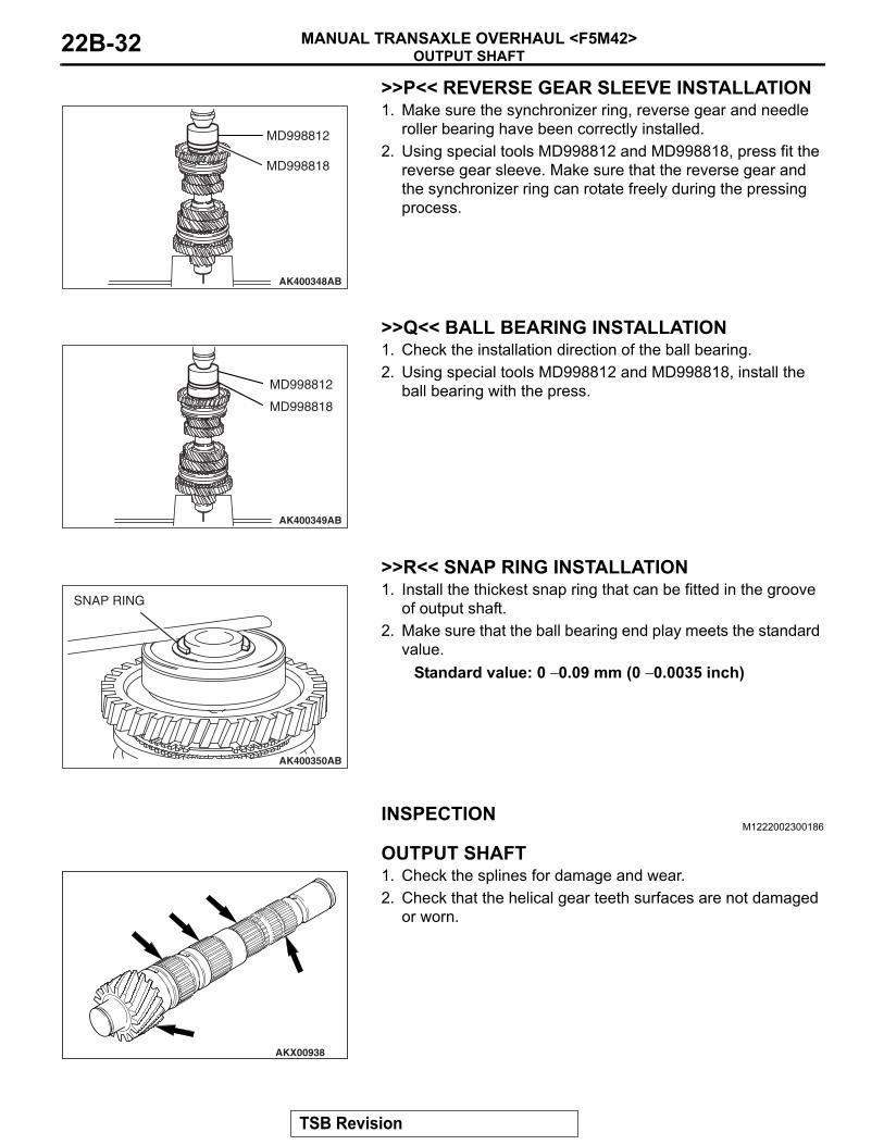
>>P<< REVERSE GEAR SLEEVE INSTALLATION
AK400348AB
MD998812
MD998818
1. Make sure the synchronizer ring, reverse gear and needle roller bearing have been correctly installed.
2. Using special tools MD998812 and MD998818, press fit the reverse gear sleeve. Make sure that the reverse gear and the synchronizer ring can rotate freely during the pressing process.
.
>>Q<< BALL BEARING INSTALLATION
AK400349AB
MD998812
MD998818
1. Check the installation direction of the ball bearing.2. Using special tools MD998812 and MD998818, install the
ball bearing with the press.
.
>>R<< SNAP RING INSTALLATION
AK400350
SNAP RING
AB
1. Install the thickest snap ring that can be fitted in the groove of output shaft.
2. Make sure that the ball bearing end play meets the standard value.
Standard value: 0 − 0.09 mm (0 − 0.0035 inch)
INSPECTIONM1222002300186
.
OUTPUT SHAFT
AKX00938
1. Check the splines for damage and wear.2. Check that the helical gear teeth surfaces are not damaged
or worn.
.
TSB Revision

OUTPUT SHAFTMANUAL TRANSAXLE OVERHAUL <F5M42> 22B-33
NEEDLE ROLLER BEARING1. Combine the needle roller bearing with the bearing sleeve
and gear, and check that it rotates smoothly without noise or play.
2. Check the needle roller bearing cage for deformation..
SYNCHRONIZER RING
AKX00915
1. Check if the clutch gear teeth are damaged or broken.2. Check internal surface for damage, wear and broken
threads.
AKX00927
AGEAR
SYNCHRO-NIZER RING
AB
3. Force the synchronizer ring toward the clutch gear and check clearance "A." If "A" is less than the limit, replace the synchronizer ring.
Minimum limit: 0.5 mm (0.020 inch)
.
OUTER SYNCHRONIZER RING/INNER SYNCHRONIZER RING/SYNCHRONIZER CONE
AK204395AD
CAUTIONWhen replacing, replace the outer ring, inner ring and cone as a set.1. Check that the clutch gear tooth surfaces and cone surfaces
are not damaged or broken.
TSB Revision
OUTPUT SHAFTMANUAL TRANSAXLE OVERHAUL <F5M42>22B-34
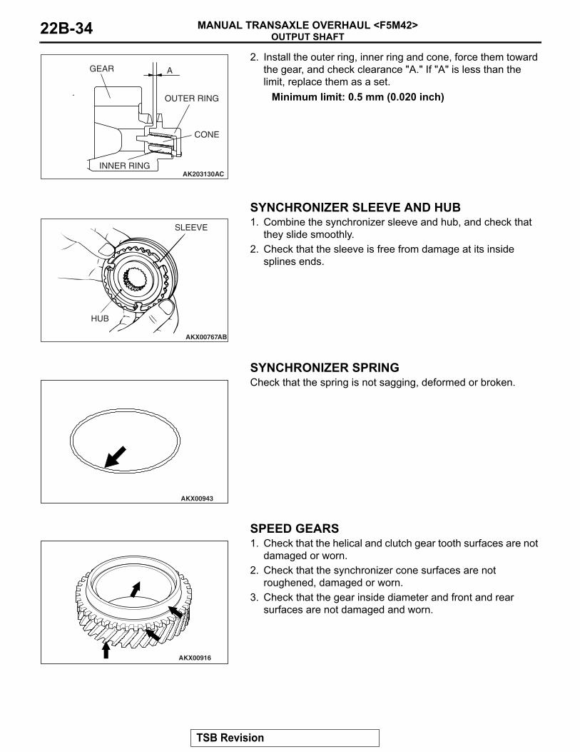
AK203130AC
A
OUTER RING
INNER RING
CONE
GEAR2. Install the outer ring, inner ring and cone, force them toward
the gear, and check clearance "A." If "A" is less than the limit, replace them as a set.
Minimum limit: 0.5 mm (0.020 inch)
.
SYNCHRONIZER SLEEVE AND HUB
AKX00767
SLEEVE
HUB
AB
1. Combine the synchronizer sleeve and hub, and check that they slide smoothly.
2. Check that the sleeve is free from damage at its inside splines ends.
.
SYNCHRONIZER SPRING
AKX00943
Check that the spring is not sagging, deformed or broken.
.
SPEED GEARS
AKX00916
1. Check that the helical and clutch gear tooth surfaces are not damaged or worn.
2. Check that the synchronizer cone surfaces are not roughened, damaged or worn.
3. Check that the gear inside diameter and front and rear surfaces are not damaged and worn.
TSB Revision
REVERSE IDLER GEARMANUAL TRANSAXLE OVERHAUL <F5M42> 22B-35
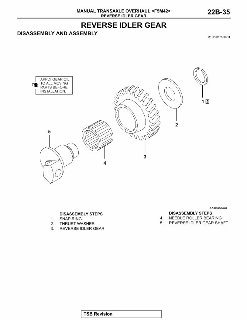
REVERSE IDLER GEARDISASSEMBLY AND ASSEMBLY
M1222012500211
AK305225
APPLY GEAR OILTO ALL MOVINGPARTS BEFOREINSTALLATION.
AC
1
2
34
5
DISASSEMBLY STEPS 1. SNAP RING2. THRUST WASHER3. REVERSE IDLER GEAR
4. NEEDLE ROLLER BEARING5. REVERSE IDLER GEAR SHAFT
DISASSEMBLY STEPS
TSB Revision
VEHICLE SPEED SENSORMANUAL TRANSAXLE OVERHAUL <F5M42>22B-36
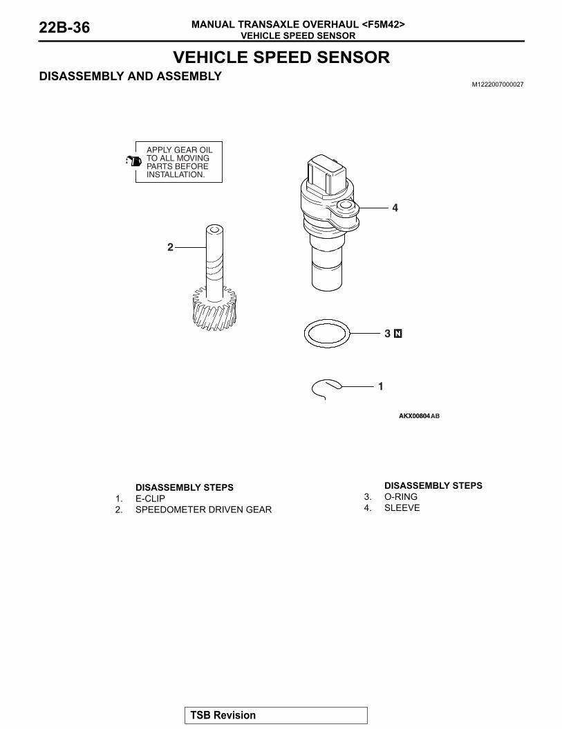
VEHICLE SPEED SENSORDISASSEMBLY AND ASSEMBLY
M1222007000027
AKX00804
APPLY GEAR OILTO ALL MOVINGPARTS BEFOREINSTALLATION.
AKX00804
4
2
3
1
AB
DISASSEMBLY STEPS 1. E-CLIP2. SPEEDOMETER DRIVEN GEAR
3. O-RING4. SLEEVE
DISASSEMBLY STEPS
TSB Revision

SELECT LEVERMANUAL TRANSAXLE OVERHAUL <F5M42> 22B-37
SELECT LEVERDISASSEMBLY AND ASSEMBLY
M1222012800160
AK403239
6
5
7 1
11 ± 1 N·m97 ± 9 in-lb
82
9 3
4
10
AB
DISASSEMBLY STEPS 1. DUST COVER2. NUT3. SPRING WASHER4. WASHER
>>A<< 5. SELECT LEVER BUSHING
6. SELECT LEVER SHOE7. SELECT LEVER
>>A<< 8. SELECT LEVER BUSHING>>A<< 9. DUST COVER
10. SELECT LEVER SHAFT
DISASSEMBLY STEPS
TSB Revision

SELECT LEVERMANUAL TRANSAXLE OVERHAUL <F5M42>22B-38
ASSEMBLY SERVICE POINT.
>>A<< DUST COVER AND SELECT LEVER BUSH-ING INSTALLATION
AKX00939
SELECT LEVERBUSHING
DUST COVERAB
Make sure the dust cover and select lever bushing installation direction is correct, and the distinguished parts are correctly assembled as shown.
TSB Revision

CONTROL HOUSINGMANUAL TRANSAXLE OVERHAUL <F5M42> 22B-39
CONTROL HOUSINGDISASSEMBLY AND ASSEMBLY
M1222013100249
AK403240
11
7
8
1
6
54
2
3
13
14
12
10
9
21.7 ± 0.3 N·m16.0 ± 0.2 ft-lb
AB
DISASSEMBLY STEPS 1. SPRING WASHER2. STOPPER BRACKET
<<A>> >>E<< 3 LOCK PIN4. INTERLOCK PLATE5. CONTROL FINGER
>>D<< 6. SPRING PIN7. STOPPER BODY
8. SPRING9. CONTROL SHAFT
>>C<< 10. AIR BREATHER11. CONTROL SHAFT BOOT
>>B<< 12. OIL SEAL>>A<< 13. NEEDLE BEARING
14. CONTROL HOUSING
DISASSEMBLY STEPS
TSB Revision

CONTROL HOUSINGMANUAL TRANSAXLE OVERHAUL <F5M42>22B-40
DISASSEMBLY SERVICE POINT.
<<A>> LOCK PIN REMOVAL
AKX00856
LOCK PIN
CONTROL FINGER
AB
Drive out the lock pin from the direction shown.
ASSEMBLY SERVICE POINTS.
>>A<< NEEDLE BEARING INSTALLATION
AK302370
NEEDLEBEARINGMODELNUMBERSTAMPEDSIDE
0 – 0.5 mm (0 – 0.02 in)
AB
CONTROL HOUSING
Press fit the needle bearing into the control housing side as shown.Make sure that the side with the model number stamped on it faces the end of the control housing as shown.
.
>>B<< OIL SEAL INSTALLATION
AKX00921
Apply gear oil (Hypoid gear oil SAE 75W-90 or 75W-85W con-forming to API classification GL-4) to the oil seal lip area.
.
TSB Revision

CONTROL HOUSINGMANUAL TRANSAXLE OVERHAUL <F5M42> 22B-41
>>C<< AIR BREATHER INSTALLATION
AKX00858
1. Apply sealant (3M™ AAD Part Number 8001 or equivalent) to the inserting portion of air breather.
AKX00772
EMBOSSMARK
AB
2. Install the air breather so that the embossed mark is in the direction shown in the illustration.
.
>>D<< SPRING PIN INSTALLATION
AK100981
CONTROLSHAFT
STOPPER BODY INSTALLATIONDIRECTION
SLITSPRING PIN
AB
Drive in the spring pin so that the slit is in the direction shown in the illustration.
.
>>E<<LOCK PIN INSTALLATION
AKX00859
Drive the lock pin in from the direction shown in the illustration.
TSB Revision

CLUTCH HOUSINGMANUAL TRANSAXLE OVERHAUL <F5M42>22B-42
CLUTCH HOUSINGDISASSEMBLY AND ASSEMBLY
M1222003700273
AK204400
4
5
6
1
2
3
7
9.8 ± 2.0 N·m87 ± 17 in-lb
AF
DISASSEMBLY STEPS 1. CLUTCH RELEASE BEARING
RETAINER>>E<< 2. OIL SEAL>>D<< 3 OIL SEAL
<<A>> >>C<< 4. OUTER RACE<<B>> >>B<< 5. ROLLER BEARING
>>A<< 6. BUSHING7. CLUTCH HOUSING
Required Special Tools:• MB990926: Installer Adapter • MB990934: Installer Adapter • MB990935: Installer Adapter• MB990938: Handle
• MD998325: Differential Oil Seal Installer • MD998346: Bearing Outer Race Remover • MD998772: Valve Spring Compressor • MD999566: Claw
DISASSEMBLY STEPS
TSB Revision
CLUTCH HOUSINGMANUAL TRANSAXLE OVERHAUL <F5M42> 22B-43
DISASSEMBLY SERVICE POINT.
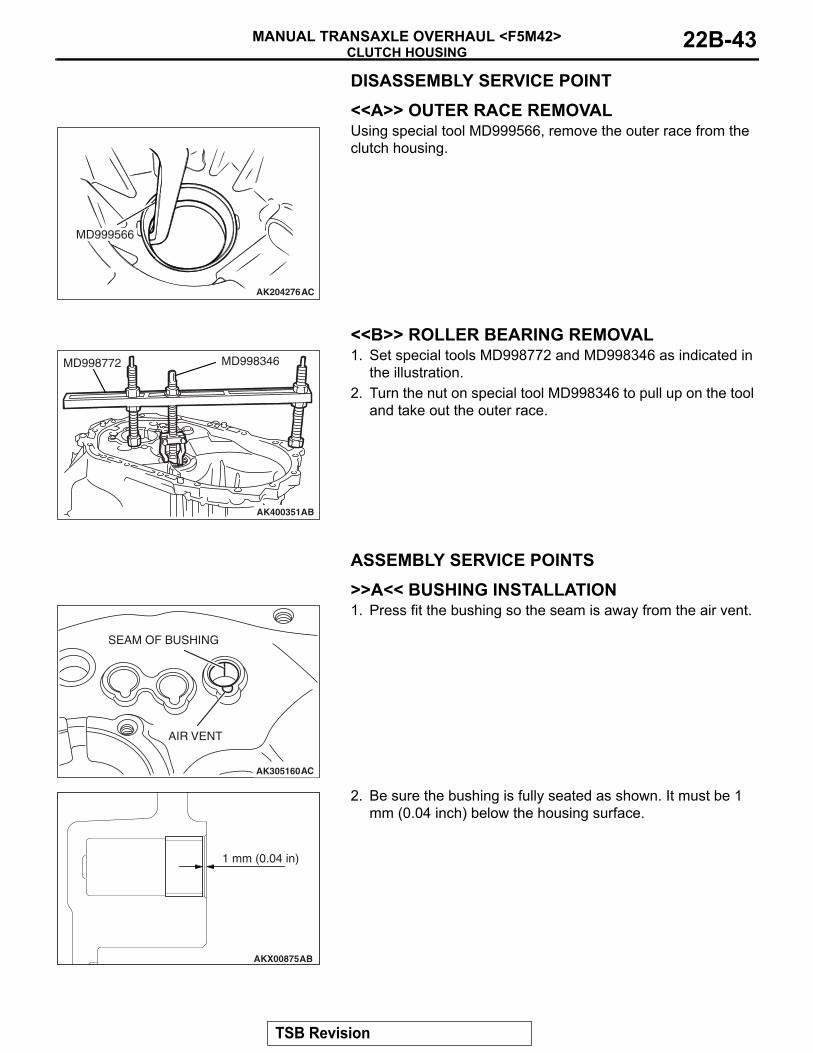
<<A>> OUTER RACE REMOVAL
AK204276
MD999566
AC
Using special tool MD999566, remove the outer race from the clutch housing.
.
<<B>> ROLLER BEARING REMOVAL
AK400351AB
MD998772 MD998346 1. Set special tools MD998772 and MD998346 as indicated in the illustration.
2. Turn the nut on special tool MD998346 to pull up on the tool and take out the outer race.
ASSEMBLY SERVICE POINTS.
>>A<< BUSHING INSTALLATION
AK305160
SEAM OF BUSHING
AIR VENT
AC
1. Press fit the bushing so the seam is away from the air vent.
AKX00875
1 mm (0.04 in)
AB
2. Be sure the bushing is fully seated as shown. It must be 1 mm (0.04 inch) below the housing surface.
.
TSB Revision

CLUTCH HOUSINGMANUAL TRANSAXLE OVERHAUL <F5M42>22B-44
>>B<< ROLLER BEARING INSTALLATION
AKX00863
MODEL NUMBERSTAMPED SIDE
AB
1. Check the installation direction of the outer race.Install the outer race so the side with the model number stamping can be seen.
AK305162AC
MB990938MB990934
2. Using special tools MB990938 and MB990934, press fit the outer race into the clutch housing.
.
>>C<< OUTER RACE INSTALLATION
AK400352AB
MB9990938
MB990935
1. Check the installation direction of the outer race.2. Using special tools MB990938 and MB990935, press fit the
outer race into the clutch housing.
.
>>D<<OIL SEAL INSTALLATION
AKX00866
1. Apply gear oil (Hypoid gear oil SAE 75W-85W conforming to API classification GL-4) to the oil seal lip.
TSB Revision

CLUTCH HOUSINGMANUAL TRANSAXLE OVERHAUL <F5M42> 22B-45
AK400353AB
MD998325
2. Using special tool MD998325, press fit the oil seal into the clutch housing.
.
>>E<< OIL SEAL INSTALLATION
AKX00868
1. Apply transmission oil (Hypoid gear oil SAE 75W-85W conforming to API classification GL-4) to the oil seal lip.
AK305167AC
MB990938MB990926
2. Using special tools MB990938 and MB990926, press fit the oil seal into the clutch housing.
TSB Revision

TRANSMISSION CASEMANUAL TRANSAXLE OVERHAUL <F5M42>22B-46
TRANSMISSION CASEDISASSEMBLY AND ASSEMBLY
M1222013400206
AKX00806
12*
5*
64 3AC
DISASSEMBLY STEPS >>C<< 1. OIL SEAL>>B<< 2. NEEDLE BEARING*
3. OIL GUIDE4. SNAP RING
>>A<< 5. BUSHING*6. TRANSAXLE
NOTE: *:Refer to the needle bearing and bushing instal-lation procedures only when replacing the transaxle case.
Required Special Tool:• MD998325: Differential Oil Seal Installer
DISASSEMBLY STEPS (Continued)
TSB Revision

TRANSMISSION CASEMANUAL TRANSAXLE OVERHAUL <F5M42> 22B-47
ASSEMBLY SERVICE POINTS.
>>A<< BUSHING INSTALLATION
AK305174
AIR VENT
AC
SEAM OF BUSHING
1. Press fit the bushing so the seam is away from the air vent.
AKX00924
3 mm (0.12 in)
AB
2. Be sure the bushing is fully seated as shown. It must be 3 mm(0.12 inch) below the housing surface.
.
>>B<< NEEDLE BEARING INSTALLATION
AKX00871
MODEL NUMBERSTAMPED SIDE
AB
1. Check the installation direction of the needle bearing.2. Press fit the needle bearing until it is flush with the case.
.
>>C<<OIL SEAL INSTALLATION
AKX00870
1. Apply gear oil (Hypoid gear oil SAE 75W-90 or 75W-85W conforming to API classification GL-4).
TSB Revision

DIFFERENTIALMANUAL TRANSAXLE OVERHAUL <F5M42>22B-48
AK305170AC
MD998325
2. Using special tool MD998325, press fit the oil seal into the transaxle case.
DIFFERENTIALDISASSEMBLY AND ASSEMBLY
M1222002500209
AKX00771
APPLY GEAR OILTO ALL MOVINGPARTS BEFOREINSTALLATION. 2
3
8
6
5
4
8
132 ± 5 N·m97 ± 4 ft-lb
17
5
2
6
9
AC
DISASSEMBLY STEPS >>D<< 1. DIFFERENTIAL DRIVE GEAR
<<A>> >>C<< 2. TAPER ROLLER BEARING>>B<< 3. LOCK PIN>>A<< 4. PINION SHAFT>>A<< 5. PINION
>>A<< 6. WASHER>>A<< 7. SIDE GEAR>>A<< 8. SPACER
9. DIFFERENTIAL CASE
Required Special Tools:• MD998801: Bearing Remover• MD998812: Installer Cap
• MD998819: Installer Adapter (40)
DISASSEMBLY STEPS
TSB Revision

DIFFERENTIALMANUAL TRANSAXLE OVERHAUL <F5M42> 22B-49
DISASSEMBLY SERVICE POINT.
<<A>> TAPER ROLLER BEARING REMOVAL
AK400354AB
MD9988011. Using special tool MD998801, support the taper roller
bearing, and then set them on the press.2. Push down on the differential case with the press and
remove the bearing.
ASSEMBLY SERVICE POINTS.
>>A<< SPACER/SIDE GEAR/WASHER/PIN-ION/PINION SHAFT INSTALLATION
AK400355
1. After a spacer has been mounted on the back surface of the side gear, install the side gear in the differential case.NOTE: When a new side gear is to be installed, mount a medium thickness spacer [0.93 − 1.00 mm (0.0366 − 0.0395 inch].
2. Set the washer on the back of each pinion, and put both pinions simultaneously in mesh with the side gears. While rotating them, install them in position.
AK400356
3. Insert the pinion shaft.
AK400357
4. Measure the backlash between the side gear and pinion.Standard value: 0 − 0.150 mm (0 − 0.0059 inch)
5. If the backlash is out of specification, select a spacer that should get the backlash within the standard value. then re-measure the backlash.NOTE: Repeat until the backlash on both sides are equal.
.
TSB Revision
DIFFERENTIALMANUAL TRANSAXLE OVERHAUL <F5M42>22B-50
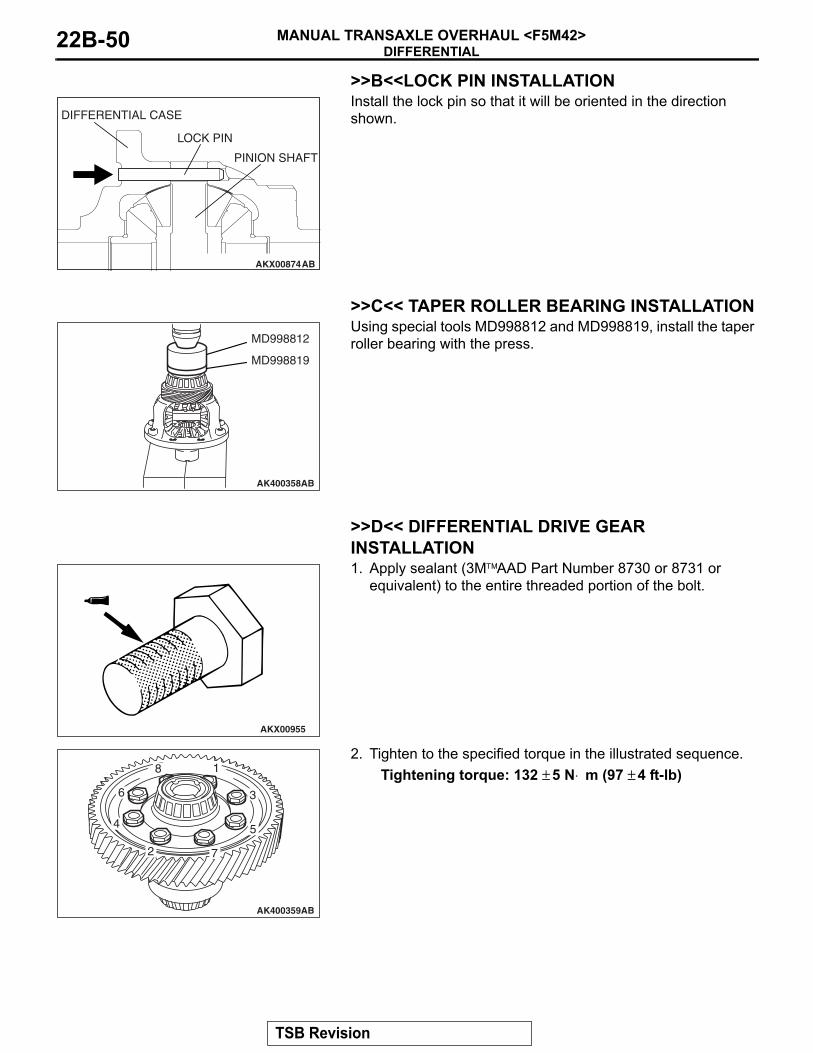
>>B<<LOCK PIN INSTALLATION
AKX00874
DIFFERENTIAL CASE
LOCK PIN
PINION SHAFT
AB
Install the lock pin so that it will be oriented in the direction shown.
.
>>C<< TAPER ROLLER BEARING INSTALLATION
AK400358AB
MD998812
MD998819
Using special tools MD998812 and MD998819, install the taper roller bearing with the press.
.
>>D<< DIFFERENTIAL DRIVE GEAR INSTALLATION
AKX00955
1. Apply sealant (3M™AAD Part Number 8730 or 8731 or equivalent) to the entire threaded portion of the bolt.
AK400359
1
2
3
4 5
6
7
8
AB
2. Tighten to the specified torque in the illustrated sequence.Tightening torque: 132 ± 5 N⋅ m (97 ± 4 ft-lb)
TSB Revision

SPECIFICATIONSMANUAL TRANSAXLE OVERHAUL <F5M42> 22B-51
SPECIFICATIONSFASTENER TIGHTENING SPECIFICATIONS
M1222012100246
ITEM SPECIFICATIONFront bearing retainer mounting bolt 18 ± 3 N⋅ m (13 ± 2 ft-lb)Clutch housing-transaxle case mounting bolt 44 ± 5 N⋅ m (32 ± 4 ft-lb)Reverse idler gear shaft mounting bolt 48 ± 6 N⋅ m (35 ± 4 ft-lb)Under cover mounting bolt 6.9 ± 0.9 N⋅ m (61 ± 8 in-lb)Control housing mounting bolt 18 ± 3 N⋅ m (13 ± 2 ft-lb)Interlock plate bolt 30 ± 3 N⋅ m (22 ± 2 ft-lb)Harness bracket bolt 18 ± 3 N⋅ m (13 ± 2 ft-lb)Poppet spring 32 ± 2 N⋅ m (24 ± 1 ft-lb)Backup light switch 32 ± 2 N⋅ m (24 ± 1 ft-lb)Vehicle speed sensor mounting bolt 3.9 ± 1.0 N⋅ m (35 ± 9 in-lb)Select lever mounting bolt 18 ± 3 N⋅ m (13 ± 2 ft-lb)Shift cable bracket mounting bolt 18 ± 3 N⋅ m (13 ± 2 ft-lb)Roll stopper bracket front, mounting bolt 90 ± 10 N⋅ m (66 ± 7 ft-lb)Roll stopper bracket rear, mounting bolt 85 ± 5 N⋅ m (63 ± 4 ft-lb)Select lever mounting nut 11 ± 1 N⋅ m (97 ± 9 in-lb)Stopper bracket mounting bolt 21.7 ± 0.3 N⋅ m (16.0 ± 0.2 ft-lb)Clutch release bearing retainer mounting bolt 9.8 ± 2.0 N⋅ m (87 ± 17 in-lb)Differential drive gear mounting bolt 132 ± 5 N⋅ m (97 ± 4 ft-lb)
GENERAL SPECIFICATIONSM1222000200387
ITEM SPECIFICATIONModel F5M42-2-V5PApplicable engine 4G69 S4 MIVECType 5-speed transaxle floor shiftGear ratio 1st 3.583
2nd 1.9473rd 1.3794th 1.0305th 0.767Reverse 3.363
Final reduction ratio 3.722Speedometer gear ratio (driven/drive) 30/36
TSB Revision

SPECIFICATIONSMANUAL TRANSAXLE OVERHAUL <F5M42>22B-52
SERVICE SPECIFICATIONSM1222000300276
ITEM STANDARD VALUE LIMITInput shaft front bearing end play mm (in) 0 − 0.12 (0 − 0.0047) −Input shaft rear bearing end play mm (in) 0 − 0.12 (0 − 0.0047) −Input shaft 5th speed gear end play mm (in) 0 − 0.09 (0 − 0.0035) −Output shaft roller bearing inner race end play mm (in) 0 − 0.12 (0 − 0.0047) −Output shaft 3rd speed gear end play mm (in) 0 − 0.09 (0 − 0.0035) −Output shaft ball bearing end play mm (in) 0 − 0.09 (0 − 0.0035) −Backlash between differential side gear and pinion mm (in) 0 − 0.150 (0 − 0.0059) −Differential case preload mm (in) 0.05 − 0.11 (0.0020 − 0.0043) −Synchronizer ring back surface to gear clearance mm (in) − 0.5 (0.020)
SEALANTS AND ADHESIVESM1222000500292
ITEM SPECIFIED SEALANTClutch housing-transaxle case mating surface Mitsubishi Part number MD997740 or equivalentControl housing-transaxle case mating surfaceUnder cover-transaxle case mating surfaceAir breather 3M™AAD Part No.8001 or equivalentDifferential drive gear bolt 3M™AAD Part No.8730 or 8731 or equivalent
LUBRICANTSM1222000400239
TRANSAXLEITEM SPECIFIED SEALANTDriveshaft oil seal lip gear oil Hypoid gear oil SAE 75W-90 or 75W-85W conforming to
API classification GL-4Input shaft oil seal lip gear oilControl shaft oil seal lip gear oilSelect lever shoe Mitsubishi Part number 0101011 or equivalent
TSB Revision

SPECIFICATIONSMANUAL TRANSAXLE OVERHAUL <F5M42> 22B-53
SNAP RINGS, SPACERS AND THRUST PLATE FOR ADJUSTMENTM1222012000272
Snap ring (For adjustment of input shaft front bearing end play) THICKNESS mm (in)
IDENTIFICATION SYMBOL
THICKNESS mm (in)
IDENTIFICATION SYMBOL
2.24 (0.0882) None 2.38 (0.0937) Brown2.31 (0.0909) Blue
Snap ring (For adjustment of input shaft rear bearing end play) (For adjustment of output shaft front bearing end play) THICKNESS mm (in)
IDENTIFICATION SYMBOL
THICKNESS mm (in)
IDENTIFICATION SYMBOL
1.43 (0.0563) Green (2) 1.59 (0.0626) Yellow (2)1.51 (0.0594) White (2)
Thrust plate (For adjustment of input shaft 5th speed gear end play)THICKNESS mm (in)
IDENTIFICATION SYMBOL
THICKNESS mm (in)
IDENTIFICATION SYMBOL
2.82 (0.1110) 0 2.98 (0.1173) 62.86 (0.1126) 2 3.02 (0.1189) 72.90 (0.1142) 3 3.06 (0.1205) 82.94 (0.1157) 5 3.10 (0.1220) 9
Snap ring (For adjustment of output shaft 3rd speed gear end play)THICKNESS mm (in)
IDENTIFICATION SYMBOL
THICKNESS mm (in)
IDENTIFICATION SYMBOL
2.81 (0.1106) Green 2.97 (0.1169) Orange2.85 (0.1122) White 3.01 (0.1185) Red2.89 (0.1138) Yellow 3.05 (0.1201) Pink2.93 (0.1154) Black 3.09 (0.1217) Blue
Snap ring (For adjustment of output shaft rear bearing end play)THICKNESS mm (in)
IDENTIFICATION SYMBOL
THICKNESS mm (in)
IDENTIFICATION SYMBOL
2.31 (0.0909) Black (2) 2.55 (0.1004) Yellow2.35 (0.0925) None 2.59 (0.1020) Black2.39 (0.0941) Blue 2.63 (0.1035) Orange2.43 (0.0957) Brown 2.67 (0.1051) Blue2.47 (0.0972) Green 2.71 (0.1067) Brown2.51 (0.0988) White
TSB Revision

SPECIFICATIONSMANUAL TRANSAXLE OVERHAUL <F5M42>22B-54
Spacer (For adjustment of differential case preload) THICKNESS mm (in)
IDENTIFICATION SYMBOL
THICKNESS mm (in)
IDENTIFICATION SYMBOL
0.71 (0.0280) 71 1.01 (0.0398) 010.74 (0.0291) 74 1.04 (0.0409) 040.77 (0.0303) 77 1.07 (0.0421) 070.80 (0.0315) 80 1.10 (0.0433) J0.83 (0.0327) 83 1.13 (0.0445) D0.86 (0.0339) 86 1.16 (0.0457) K0.89 (0.0350) 89 1.19 (0.0469) L0.92 (0.0362) 92 1.22 (0.0480) G0.95 (0.0374) 95 1.25 (0.0492) M0.98 (0.0386) 98
Spacer (For adjustment of backlash between differential side gear and pinion)THICKNESS mm (in)
IDENTIFICATION SYMBOL
THICKNESS mm (in)
IDENTIFICATION SYMBOL
0.76 − 0.84 (0.0299 − 0.0330) − 1.06 − 1.14 (0.0417 − 0.0449) −0.81 − 0.89 (0.0319 − 0.0350) − 1.11 − 1.19 (0.0437 − 0.0469) −0.86− 0.94 (0.0339 − 0.0370) − 1.16 − 1.24 (0.0457 − 0.0488) −0.91 − 0.99 (0.0358 − 0.0390) − 1.21 − 1.29 (0.0476 − 0.0508) −0.96 − 1.04 (0.0378 − 0.0409) − 1.26 − 1.34 (0.0496 − 0.0528) −1.01 − 1.09 (0.0398 − 0.0429) −
TSB Revision