manual modbus communication protocol ref615r · 2019-08-23 · modbus serial protocol uses two link...
TRANSCRIPT

—RELION® PROTECTION AND CONTROL
REF615RModbus Communication ProtocolManual


Document ID: 1MRS240047-IBIssued: 2019-07-02
Revision: CProduct version: 4.1
© Copyright 2019 ABB. All rights reserved

Copyright
This document and parts thereof must not be reproduced or copied without writtenpermission from ABB, and the contents thereof must not be imparted to a third party, norused for any unauthorized purpose.
The software or hardware described in this document is furnished under a license and maybe used, copied, or disclosed only in accordance with the terms of such license.
TrademarksABB and Relion are registered trademarks of the ABB Group. All other brand or productnames mentioned in this document may be trademarks or registered trademarks of theirrespective holders.
WarrantyPlease inquire about the terms of warranty from your nearest ABB representative.
www.abb.com/mediumvoltage
www.abb.com/substationautomation

Disclaimer
The data, examples and diagrams in this manual are included solely for the concept orproduct description and are not to be deemed as a statement of guaranteed properties. Allpersons responsible for applying the equipment addressed in this manual must satisfythemselves that each intended application is suitable and acceptable, including that anyapplicable safety or other operational requirements are complied with. In particular, anyrisks in applications where a system failure and/or product failure would create a risk forharm to property or persons (including but not limited to personal injuries or death) shallbe the sole responsibility of the person or entity applying the equipment, and those soresponsible are hereby requested to ensure that all measures are taken to exclude ormitigate such risks.
This product has been designed to be connected and communicate data and informationvia a network interface which should be connected to a secure network. It is the soleresponsibility of the person or entity responsible for network administration to ensure asecure connection to the network and to take the necessary measures (such as, but notlimited to, installation of firewalls, application of authentication measures, encryption ofdata, installation of anti virus programs, etc.) to protect the product and the network, itssystem and interface included, against any kind of security breaches, unauthorized access,interference, intrusion, leakage and/or theft of data or information. ABB is not liable forany such damages and/or losses.
This document has been carefully checked by ABB but deviations cannot be completelyruled out. In case any errors are detected, the reader is kindly requested to notify themanufacturer. Other than under explicit contractual commitments, in no event shall ABBbe responsible or liable for any loss or damage resulting from the use of this manual or theapplication of the equipment.

Conformity
This product complies with the directive of the Council of the European Communities onthe approximation of the laws of the Member States relating to electromagneticcompatibility (EMC Directive 2004/108/EC) and concerning electrical equipment for usewithin specified voltage limits (Low-voltage directive 2006/95/EC). This conformity isthe result of tests conducted by ABB in accordance with the product standards EN 50263and EN 60255-26 for the EMC directive, and with the product standards EN 60255-1 andEN 60255-27 for the low voltage directive. The product is designed in accordance with theinternational standards of the IEC 60255 series and ANSI C37.90. This product complieswith the UL 508 certification.

Table of contents
Section 1 Introduction............................................................................5This manual.............................................................................................. 5Intended audience.................................................................................... 5Product documentation.............................................................................6
Product documentation set..................................................................6Document revision history................................................................... 6Related documentation........................................................................6
Symbols and conventions.........................................................................7Symbols...............................................................................................7Document conventions........................................................................ 7
Section 2 Modbus standard...................................................................9Serial communication............................................................................... 9Ethernet communication........................................................................... 9Application data implementation ............................................................10Terms and definitions............................................................................. 10Documentation........................................................................................11
Section 3 Vendor-specific implementation.......................................... 13Modbus link alternatives......................................................................... 13
Serial link........................................................................................... 13Modbus serial link parameters......................................................13Modbus serial diagnostic counters............................................... 15Character framing in different serial link modes........................... 15
TCP/IP link.........................................................................................16TCP/IP interface configuration......................................................16Modbus TCP/IP diagnostic counters............................................ 18
Supported function codes.......................................................................19Application functions..........................................................................19Diagnostic functions.......................................................................... 19Exception codes................................................................................ 20
Application data...................................................................................... 21Modbus data objects......................................................................... 21Modbus data implementation............................................................ 21Data mapping principles.................................................................... 22
Data in monitoring direction..........................................................22
Table of contents
REF615R 1Communication Protocol Manual

One-bit data mapping...................................................................23Data in control direction................................................................23
Digital input data................................................................................23Multiple digital inputs mapping..................................................... 24
Measurand registers..........................................................................25Primary and per-unit values..........................................................25Register sizes............................................................................... 26Time of update..............................................................................26
Control operations............................................................................. 27Control functions...........................................................................27Control operations through 4X register structures........................28Additional control operation features............................................ 30
System status registers .................................................................... 31SSR1............................................................................................ 32SSR2 ........................................................................................... 32SSR3 ........................................................................................... 33SSR4 ........................................................................................... 34SSR5 ........................................................................................... 35SSR6 ........................................................................................... 35
User-definable data........................................................................... 36User definable registers................................................................36User definable bits........................................................................36Data exceptions............................................................................37Data properties.............................................................................37Unmapped data locations.............................................................37UDR data configuration................................................................ 37UDR register value manipulation..................................................37
Event records ....................................................................................38Single event record structure........................................................39Single event record reading..........................................................40Other event record registers.........................................................41Multiple event records reading..................................................... 41
Fault records .....................................................................................43Fault record structure................................................................... 44Fault record reading..................................................................... 45Other fault record registers...........................................................46
Parameter setting group selection.....................................................47Time synchronization ........................................................................47
Real-time clock structure.............................................................. 47Writing to real-time structures.......................................................48
Table of contents
2 REF615RCommunication Protocol Manual

Device information.............................................................................48ASCII character coding.................................................................49ASCII string syntax....................................................................... 50
Reset time structure...........................................................................50Accessing of non-protocol-mapped data........................................... 51
Section 4 Modbus parameters and diagnostics.................................. 53Parameter list..........................................................................................53Monitored data........................................................................................54
Section 5 Glossary.............................................................................. 57
Table of contents
REF615R 3Communication Protocol Manual

4

Section 1 Introduction
1.1 This manual
The communication protocol manual describes a communication protocol supported bythe protection relay. The manual concentrates on vendor-specific implementations.
1.2 Intended audience
This manual addresses the communication system engineer or system integratorresponsible for pre-engineering and engineering the communication setup in a substationfrom a protection relay's perspective.
The system engineer or system integrator must have a basic knowledge of communicationin protection and control systems and thorough knowledge of the specific communicationprotocol.
1MRS240047-IB C Section 1Introduction
REF615R 5Communication Protocol Manual

1.3 Product documentation
1.3.1 Product documentation set
Pla
nnin
g &
pu
rcha
se
Eng
inee
ring
Inst
alla
tion
Com
mis
sion
ing
Ope
ratio
n
Mai
nten
ance
Dec
omm
issi
onin
g,de
inst
alla
tion
& d
ispo
sal
Quick installation guideBrochureProduct guideOperation manualInstallation manualEngineering manualTechnical manualApplication manualCommunication protocol manualIEC 61850 engineering guidePoint list manual
GUID-3983CF6E-DF22-4183-B387-D67F3BB9593C V1 EN
Figure 1: The intended use of documents during the product life cycle
1.3.2 Document revision historyDocument revision/date Product version HistoryA/2013-11-22 4.0 First release
B/2016-10-24 4.1 Content updated to correspond to theproduct version
C/2019-07-02 4.1 Content updated
Download the latest documents from the ABB Web sitehttp://www.abb.com/substationautomation.
1.3.3 Related documentationName of the document Document IDModbus Point List Manual 1MRS240052-IB
Section 1 1MRS240047-IB CIntroduction
6 REF615RCommunication Protocol Manual

Product-specific point list manuals and other product series- and product-specificmanuals can be downloaded from the ABB Web sitehttp://www.abb.com/substationautomation.
1.4 Symbols and conventions
1.4.1 Symbols
The caution icon indicates important information or warning related to theconcept discussed in the text. It might indicate the presence of a hazardwhich could result in corruption of software or damage to equipment orproperty.
The information icon alerts the reader of important facts and conditions.
The tip icon indicates advice on, for example, how to design your projector how to use a certain function.
Although warning hazards are related to personal injury, it is necessary to understand thatunder certain operational conditions, operation of damaged equipment may result indegraded process performance leading to personal injury or death. Therefore, complyfully with all warning and caution notices.
1.4.2 Document conventions
A particular convention may not be used in this manual.
• Abbreviations and acronyms are spelled out in the glossary. The glossary alsocontains definitions of important terms.
• Push button navigation in the LHMI menu structure is presented by using the pushbutton icons.To navigate between the options, use and .
• Menu paths are presented in bold.Select Main menu/Settings.
• WHMI menu names are presented in bold.Click Information in the WHMI menu structure.
• LHMI messages are shown in Courier font.To save the changes in nonvolatile memory, select Yes and press .
1MRS240047-IB C Section 1Introduction
REF615R 7Communication Protocol Manual

• Parameter names are shown in italics.The function can be enabled and disabled with the Operation setting.
• Parameter values are indicated with quotation marks.The corresponding parameter values are "Enabled" and "Disabled".
• Input/output messages and monitored data names are shown in Courier font.When the function picks up, the PICKUP output is set to TRUE.
• Dimensions are provided both in inches and mm. If it is not specifically mentioned,the dimension is in mm.
Section 1 1MRS240047-IB CIntroduction
8 REF615RCommunication Protocol Manual

Section 2 Modbus standard
Modbus is a communication protocol developed by the Modicon company in the 1970’s.Originally it was used for communication in PLCs and RTU devices. Later on the Modbusprotocol has been used in a variety of different device applications. Today the Modbusprotocol is mainly used over serial communication networks and Ethernet.
The Modbus serial communication and the Ethernet based Modbus TCP/IPcommunication in this protection relay follow the specifications maintained by ModbusOrganization.
Modbus communication reference guides are downloadable fromTechnical Resources at www.modbus.org.
2.1 Serial communication
Modbus is a master-slave protocol when it is used over serial communication networks.This protection relay implements the slave side of the protocol. Depending on the chosenphysical serial interface it is possible to build multidrop networks or point-to-pointcommunication connections.
There can only be one Modbus master unit on a Modbus serial network. The Modbusmaster unit communicates with one Modbus slave unit at a time. Usually the master reads,or scans, data from the slaves cyclically. The master can also write data or give commandsto the slave units. Each slave unit has a unique unit address. Thus, the master can identifythe slave with which it communicates. The Modbus standard also defines the possibilityfor Master broadcast transmissions.
Modbus serial protocol uses two link modes: Modbus RTU and Modbus ASCII. Bothmodes are supported by this protection relay.
2.2 Ethernet communication
Modbus communication over Ethernet TCP/IP is of client-server type. This protectionrelay operates as a Modbus server.
1MRS240047-IB C Section 2Modbus standard
REF615R 9Communication Protocol Manual

Modbus TCP/IP connection is established when the Modbus client opens a TCP socketconnection to the Modbus server. The socket port 502 on the TCP/IP stack is reserved forModbus. If the connection request is accepted by the server, the client can startcommunicating with the server unit.
Protection relays can usually accept several simultaneous Modbus TCP/IP clientconnections even though the number of connections is limited. It is possible to configurethe protection relay to only accept socket connection requests from known client IPaddresses.
2.3 Application data implementation
This protection relay is designed to operate with a wide range of different Modbus mastersand clients. The Modbus memory map offers the possibility to view protection relay'sinternal process data in a simple I/O map style which is mainly aimed at PLC masters andother process automation devices. Time-tagged, chronological event lists and faultrecords can be read over the Modbus interface. These data are more suitable for SCADAtype of Modbus masters.
The Modbus standard defines four main memory areas for mapping protection relay'sprocess data. Due to its open nature, the Modbus standard does not define exactly whattype of data should be mapped to each memory area. The Modbus mapping approach ofthe protection relay ensures that the same process data are readable from as many Modbusmemory areas as possible. The users may then choose the memory areas that are mostsuitable for their Modbus master systems.
2.4 Terms and definitions
Modbus data appear in different memory areas in the Modbus device. The four mostcommon areas are coils, digital inputs, input registers and holding registers. These are alsoreferred to as 0X, 1X, 3X and 4X areas respectively.
Modbus defines addressing in two ways: PLC addressing starts from address 1 and regularModbus data addressing starts from 0. For example, a holding register at PLC address 234can be referred to either as 4X register 234 or as 40234. The regular Modbus addressing,that is the PLC address decremented by one, is shown when analyzing the Modbus trafficon the physical network.
Listings and references to the Modbus data in this documentation followthe PLC addressing scheme. Addresses start from 1.
Section 2 1MRS240047-IB CModbus standard
10 REF615RCommunication Protocol Manual

Refer also to the Modbus protocol standard documentation that can be found for free atwww.modbus.org.
2.5 Documentation
The ANSI Modbus point list manual covers the data points specific to REF615R.
A newer SW version of REF615R may contain additional Modbus points.
1MRS240047-IB C Section 2Modbus standard
REF615R 11Communication Protocol Manual

12
Section 3 Vendor-specific implementation
3.1 Modbus link alternatives
Modbus communication is possible over the serial communication interface, over theEthernet interface, or over both interfaces simultaneously.
3.1.1 Serial link
Modbus serial communication requires that the protection relay variant is equipped witha serial interface card at the slot X000. The serial interface card can contain one or twoserial interfaces.
The Modbus link mode can be either Modbus RTU or Modbus ASCII.
Modbus serial communication can run on two separate serial ports simultaneously. TheModbus serial link characteristics can be different on the two ports. This applies also to theModbus RTU and ASCII link modes and the unit address.
Documentation concerning the Modbus serial link messages and theModbus standard can be obtained from www.modbus.org.
3.1.1.1 Modbus serial link parameters
Serial link setting parameters can be accessed with Parameter Setting tool in PCM600,WHMI or via the LHMI path Configuration/Communication/Modbus.
In the LHMI parameter names end either with number 1 or with number2. The numbers refer to two separate serial ports, that is the instances 1 and2.
AddressEach serial link can be given a separate unit address.
1MRS240047-IB C Section 3Vendor-specific implementation
REF615R 13Communication Protocol Manual

End delayThe end of message delay, or timeout, is used only in the Modbus RTU link mode.According to the Modbus standard, an idle period of 3.5 characters, that is the time it takesto transmit 3.5 characters with the used baud rate, defines the end of a Modbus RTU framein the RTU mode. This parameter can be given with the accuracy of one character. Thedefault setting is three characters but the user can increase or decrease the value.
In a multidrop RS-485 Modbus network the unit may detect and receiveresponse messages from other slave units. Thus, consider the minimumsilent time between the response frame and the beginning of master’s nextrequest frame when setting the end delay in Modbus RTU mode.
This parameter has no meaning in the Modbus ASCII link mode.
Start delayThe intraframe delay on serial Modbus RTU link is defined as a silent interval of 3.5characters. The delay is essential for Modbus devices to recognize the beginning and endof each RTU frame. If the end delay is decreased in this protection relay, the responsemessages may be transmitted too fast according to the link standard especially true withslower baud rates. The start delay parameter adds idle characters before the transmission,thus increasing the silent interval between the Modbus RTU link frames. The start delaydefault setting is four idle (silent) characters.
To set the timing properly, consider also how the other slave units in amultidrop RS-485 network detect the Modbus traffic between the masterand this protection relay.
Serial portIt is possible to define which serial port is used for separate Modbus serial instances:“COM1” or “COM2”. The serial communication instance is not active if this parameter isset to “Not in use.”
If this protocol does not operate as expected, make sure that other serialprotocols are not using the COM port as well.
Section 3 1MRS240047-IB CVendor-specific implementation
14 REF615RCommunication Protocol Manual

Baud rate is defined on the serial driver side and are therefore located viathe LHMI paths Configuration/Communication/COM1 andConfiguration/Communication/COM2.
3.1.1.2 Modbus serial diagnostic counters
Modbus Serial diagnostic counters can be viewed via the LHMI path Monitoring/Communication/Modbus/Serial.
Counters related to the possible Modbus serial instances 1...2 have the suffixes 1…2 (N).The counters show complete Modbus protocol link frames and Modbus errors. The serialcommunication drivers (COM1, COM2) maintain their own counters for lower levelserial communication diagnostics.
Table 1: Serial diagnostic counters
Counter DescriptionReceived frames N Total amount of received Modbus frames. For example, the Modbus frames that
are addressed to this instance.
Transmitted frames N Total amount of transmitted Modbus responses.
Cksm Err N Total amount of detected Modbus checksum errors.The Modbus instance only calculates checksums of Modbus frames that contain aproper link address. All other incoming Modbus frames are discarded.
Transmitted Exc A N Total amount of exception responses 1 and 2.These exception responses usually reveal configuration errors on the Modbusclient side. Either the client uses a request function code which is not supported orthe requested Modbus point(s) does not exist.
Transmitted Exc B N Total amount of exception responses 3.These exceptions usually reveal the protection relay application level rejections.That is, the protection relay application rejects the request at this moment, underthe current circumstances. The exception can also mean that the value in theModbus write request is out of range.
Status N Shows the value "True" if the serial instance is in use. This indicates that theModbus client is connected. The status is checked every second, and when theModbus client disconnects, the Modbus server waits for 15 seconds to update thestatus to "False". Resetting of all diagnostic counters in the instance N is done bywriting value "True" into this same Status N object.
3.1.1.3 Character framing in different serial link modes
According to the Modbus standard, the character length in the Modbus RTU mode shouldbe 11 bits and in Modbus ASCII mode 10 bits. It is possible to freely define the characterparity: even, odd or no parity. No parity means that the bit length of the serial character isreduced by one. Thus, the character is compensated with an additional stop bit.
1MRS240047-IB C Section 3Vendor-specific implementation
REF615R 15Communication Protocol Manual

Table 2: RTU characters
Coding system 8-bit binaryBits percharacter
1 start bit8 data bits, the least significant bit is sent first1 bit for even/odd parity; no bit if parity is not used1 stop bit if parity is used; 2 stop bits if parity is not used
Table 3: ASCII characters
Coding system Two ASCII characters representing a hexadecimal numberBits percharacter
1 start bit7 data bits, the least significant bit is sent first1 bit for even/odd parity; no bit if parity is not used1 stop bit if parity is used; 2 stop bits if parity is not used
3.1.2 TCP/IP link
The protection relay operates as a Modbus TCP/IP server. A Modbus TCP/IP client canestablish a connection to the protection relay through the standardized TCP socket port502.
The Modbus TCP/IP interface of the protection relay can be configured to accept up to fivesimultaneous Modbus client connections. It is possible to grant connections only to thepredefined TCP/IP clients. The write authority of the Modbus TCP/IP client isconfigurable.
Modbus TCP usually shares the Ethernet connection with the otherEthernet based protocols of the protection relay. The number of Ethernetbased clients that can be simultaneously connected to the protection relayis restricted.
3.1.2.1 TCP/IP interface configuration
The Modbus TCP/IP protocol uses the Ethernet interface. The general setup parameters ofEthernet, for example the protection relay's own IP address, are found via the LHMI pathConfiguration/Communication/Ethernet.
Client connectionsThe Modbus TCP/IP server accepts as many simultaneous client connections as definedwith the Max TCP/IP clients parameter:
Section 3 1MRS240047-IB CVendor-specific implementation
16 REF615RCommunication Protocol Manual

• The setting range for the parameter is 0...5.• If the parameter value is zero, the Modbus TCP/IP server connection is not in use.• The parameter works in conjunction with the parameters of a registered Modbus
TCP/IP client.
When client X reconnects, the old connection of that client is disconnected and the newconnection is accepted to avoid zombie clients. When the maximum number of clients areconnected, a new connection request is handled as follows:
• If there are unregistered clients connected, the one with the longest silent period isdisconnected and a new connection is accepted.
• If there are only registered clients connected, the new connection request is rejected.
It is possible to predefine the client or clients which are always granted Modbus TCP/IPconnections by registering the clients' IP addresses. For example, if four concurrentconnections are allowed and three of them are registered, they are seen as Clientconnection 1...Client connection 3. These three registered connections are then dedicatedto certain clients only and the fourth connection is available to other clients.
Client IP addressesThere are five Modbus setting parameters for Modbus client IP addresses. The parametervalue "0.0.0.0" indicates that the client IP address is not defined.
If there are, for example, four available TCP/IP connections defined and one of theconnections is to be dedicated for a certain client X, enter the client X's IP address to theClient IP1 parameter. The IP addresses of the Modbus clients 2..4 can be set to "0.0.0.0".The setting of the Modbus client5 IP address has no meaning in this example as theconnection is not in use. In this example, the TCP/IP session 1 is dedicated to the client Xwhich means that this registered client X is always able to connect to the protection relay.Unregistered clients can connect to sessions 2...4. However, an unregistered clientconnection request can be rejected if sessions 2...4 are already occupied. The writeauthority can also be assigned differently for registered TCP/IP clients.
Client's write authorityThe registering of a Modbus client affects the client's write authority and the reading oflatched Modbus data.
The TCP write authority parameter can be set to three different states:
• 0 = No write authority for any Modbus TCP/IP client• 1 = Write authority only for registered Modbus TCP/IP clients• 2 = Write authority for all Modbus TCP/IP clients
1MRS240047-IB C Section 3Vendor-specific implementation
REF615R 17Communication Protocol Manual
The possible blocking of write operation does not include the selection write operationthat has to be done to read out Modbus event and fault record structures.
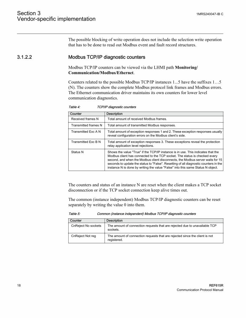
3.1.2.2 Modbus TCP/IP diagnostic counters
Modbus TCP/IP counters can be viewed via the LHMI path Monitoring/Communication/Modbus/Ethernet.
Counters related to the possible Modbus TCP/IP instances 1...5 have the suffixes 1…5(N). The counters show the complete Modbus protocol link frames and Modbus errors.The Ethernet communication driver maintains its own counters for lower levelcommunication diagnostics.
Table 4: TCP/IP diagnostic counters
Counter DescriptionReceived frames N Total amount of received Modbus frames.
Transmitted frames N Total amount of transmitted Modbus responses.
Transmitted Exc A N Total amount of exception responses 1 and 2. These exception responses usuallyreveal configuration errors on the Modbus client’s side.
Transmitted Exc B N Total amount of exception responses 3. These exceptions reveal the protectionrelay application level rejections.
Status N Shows the value "True" if the TCP/IP instance is in use. This indicates that theModbus client has connected to the TCP socket. The status is checked everysecond, and when the Modbus client disconnects, the Modbus server waits for 15seconds to update the status to "False". Resetting of all diagnostic counters in theinstance N is done by writing the value "False" into this same Status N object.
The counters and status of an instance N are reset when the client makes a TCP socketdisconnection or if the TCP socket connection keep alive times out.
The common (instance independent) Modbus TCP/IP diagnostic counters can be resetseparately by writing the value 0 into them.
Table 5: Common (instance independent) Modbus TCP/IP diagnostic counters
Counter DescriptionCnReject No sockets The amount of connection requests that are rejected due to unavailable TCP
sockets.
CnReject Not reg The amount of connection requests that are rejected since the client is notregistered.
Section 3 1MRS240047-IB CVendor-specific implementation
18 REF615RCommunication Protocol Manual

3.2 Supported function codes
3.2.1 Application functionsTable 6: Supported application functions
Functioncode
Name Description
01 Read coil status Reads the status of discrete outputs.
02 Read digital input status Reads the status of discrete inputs.
03 Read holding registers Reads the contents of output registers.
04 Read input registers Reads the contents of input registers.
06 Preset single register Sets the value of a holding register.
08 Diagnostics Checks the communication system betweenthe master and the slave.
16 Preset multiple registers Sets the value of multiple holding registers.
23 Read/write holding registers Exchanges holding registers in one query.
3.2.2 Diagnostic functions
The diagnostic functions are only intended for serial communication. However, the serialdiagnostic counters can be read, but not reset, via the Modbus TCP/IP interface. The serialline cannot be forced to the listen mode via the Modbus TCP/IP interface.
Table 7: Supported diagnostic subfunctions
Functioncode
Name Description
00 Return query data The data in the query data field is returned(looped back) in the response. The entireresponse is identical to the query.
01 Restart communication option The slaves peripheral port is initialized andrestarted and the communication eventcounters are cleared. Before this, a normalresponse will be sent provided that the port isnot in the listen only mode. If the port is in thelisten only mode, no response will be sent.
04 Force listen only mode The slave is forced to enter the listen onlymode for Modbus communication.
10 Clear counters and diagnostic register All counters and the diagnostic register arecleared.
11 Return bus message count The response returns the number ofmessages in the communication systemdetected by the slave since its last restart,clear counters operation or power up.
Table continues on next page
1MRS240047-IB C Section 3Vendor-specific implementation
REF615R 19Communication Protocol Manual
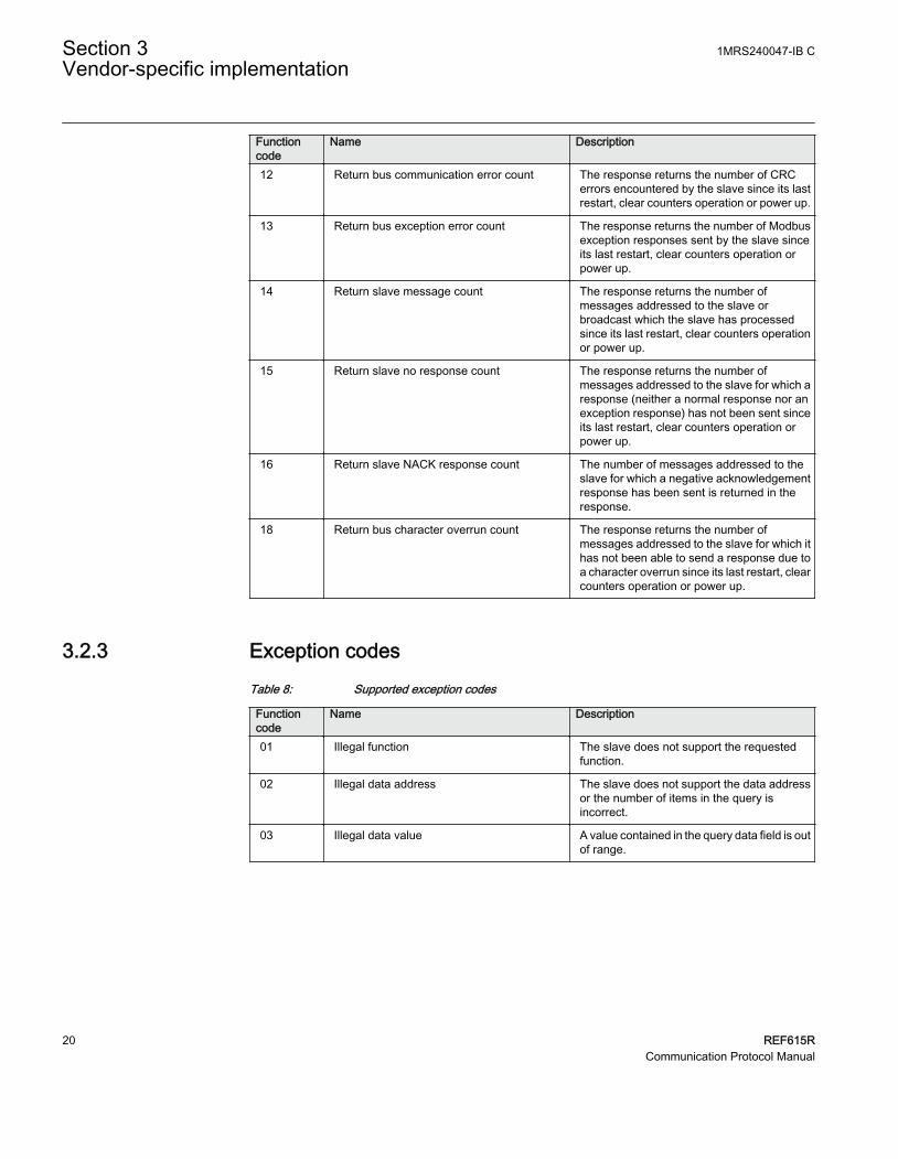
Functioncode
Name Description
12 Return bus communication error count The response returns the number of CRCerrors encountered by the slave since its lastrestart, clear counters operation or power up.
13 Return bus exception error count The response returns the number of Modbusexception responses sent by the slave sinceits last restart, clear counters operation orpower up.
14 Return slave message count The response returns the number ofmessages addressed to the slave orbroadcast which the slave has processedsince its last restart, clear counters operationor power up.
15 Return slave no response count The response returns the number ofmessages addressed to the slave for which aresponse (neither a normal response nor anexception response) has not been sent sinceits last restart, clear counters operation orpower up.
16 Return slave NACK response count The number of messages addressed to theslave for which a negative acknowledgementresponse has been sent is returned in theresponse.
18 Return bus character overrun count The response returns the number ofmessages addressed to the slave for which ithas not been able to send a response due toa character overrun since its last restart, clearcounters operation or power up.
3.2.3 Exception codesTable 8: Supported exception codes
Functioncode
Name Description
01 Illegal function The slave does not support the requestedfunction.
02 Illegal data address The slave does not support the data addressor the number of items in the query isincorrect.
03 Illegal data value A value contained in the query data field is outof range.
Section 3 1MRS240047-IB CVendor-specific implementation
20 REF615RCommunication Protocol Manual

3.3 Application data
3.3.1 Modbus data objects
The Modbus protocol in REF615R is built on top of the internal IEC 61850 data model.Thus, the Modbus application data objects, proprietary events and MCD bits are derivedfrom IEC 61850 data objects and data set reporting. REF615R has a predefined IEC 61850data set configuration. In other words, it is predefined which internal data object changesthe 615 series protection relays detect.
The available Modbus indications in REF615R are generally selected from the IEC 61850indications residing in data sets. Objects that do not reside in any data set are updated tothe Modbus database slower. This concerns, for example, some measurand registervalues. Fast changes in these object values may not be detected or propagated to theModbus database. However, the latest value of these objects is always found in theModbus database.
For a list of the available data objects, see the point list manual.
3.3.2 Modbus data implementation
The numeric register locations used in this section are for examplepurposes only. The real Modbus register locations are in the protectionrelay's memory map.
The protection relay is internally modeled according to the IEC 61850 standard. TheModbus protocol is implemented on top of this model. However, not all features of theIEC61850 data model are available through the Modbus interface.
The Modbus protocol standard defines one-bit digital data and 16-bit register data as RTUapplication data alternatives. The protocol does not define exactly how this protocolapplication data should be used by an protection relay application. The usage depends onthe protection relay implementation.
Change events and time synchronizationThe Modbus standard does not define event reporting or time synchronization procedures.Proprietary solutions are introduced in this protection relay to support thesefunctionalities.
1MRS240047-IB C Section 3Vendor-specific implementation
REF615R 21Communication Protocol Manual

Control operationsThe Modbus standard defines data types 0X for coils and 4X for holding registers to beused for control operations.
Control operations include automatic checking for authorization and local and remoteblockings as well as preventing simultaneous controlling by multiple clients.
Application data compatibilityThis protection relay is designed to operate with a wide range of Modbus masters spanningfrom industrial PLCs to substation SCADA devices. The application solutions have beenchosen to achieve the highest possible level of compatibility with the systems.
• Application data is readable in many different Modbus memory areas. Digital data isreadable as bits or packed bits in registers.
• Both 16- and 32-bit register sizes are used for measurands.• The proprietary Modbus event buffer can be read in many different ways. A master
can continuously read and log change events in real time or, for example, read an Nnumber of latest events on demand.
• Change detection data can be used as an alternative to the event record reading tocatch fast indication data transitions between the master scans.
• The Modbus fault record gives a summary of the captured analog quantities andprotection stages picking up and possibly tripping during a fault.
• The addressing of the application data in the documentation and tools follows the so-called Modbus-PLC addressing principle, where the base address 1 is used. Theapplication data addressing in this protection relay spans between 1 and 9999.
3.3.3 Data mapping principles
Modbus data is organized sequentially. This is the most efficient organization methodsince the master normally scans the Modbus data in blocks.
3.3.3.1 Data in monitoring direction
All data in the monitoring direction is available through the 4X memory area. Thisincludes the digital indication data which is also readable in the 1X and 0X areas.
All register structures are located in the 4X area.
The Modbus data may contain empty bits or registers within the sequential data areas.These bits and registers are intended for possible future expansion. Reading this data doesnot result in any Mobdus exception response. The value in these bits or registers is alwayszero.
Section 3 1MRS240047-IB CVendor-specific implementation
22 REF615RCommunication Protocol Manual

3.3.3.2 One-bit data mapping
All one-bit data in the protection relay is readable either from the 0X or 1X memory area.The Modbus bit point addresses are similar regardless of the memory area.One-bit data isalso available in 4X register memory area as bit-packed 16-bit registers. The bit locationsfollow a pattern similar to the 0X and 1X locations.
3.3.3.3 Data in control direction
Protection relay controls, set points and acknowledgements are mapped to Modbus 0Xdata (coils). Coils can only be operated one by one.
Currently the ANSI implementation of controls via the Modbus protocol are restricted tothe 4X registers map.
Some control bits are packed bits in the 4X control register structures. The 4X controlstructure contains a password which has to be given before starting control operations.
3.3.4 Digital input data
As the indication signals related to protection applications often change rapidly, theModbus master may not detect all the changes.
Momentary position and momentary change detection bitsIn this protection relay, indications are shown as two adjacent Modbus bits in the Modbusmemory map. The two bits represent the momentary position and the momentary changedetection state of the indication.
1MRS240047-IB C Section 3Vendor-specific implementation
REF615R 23Communication Protocol Manual

MOM
MCD
LATCH
A070894 V4 EN
Figure 2: Change detection bit
If the momentary value of an indication bit has changed two times or more since the masterlast read it, the MCD bit is set to one. When the MCD bit has been read, it is reset to zero.Since the indications usually are 1 (active), it is easy to detect an indication activation bycombining the MOM and MCD bits using a logical OR operation (MOM+MCD). Themomentary position bit and the MCD bit of a certain indication point always occur as pairsin the Modbus memory map.
The MCD bit states are client-dependent. The MCD bit is only reset for the specificModbus client that reads it. Thus, other Modbus clients may still receive value 1 from thesame MCD bit when it is read.
MOM indication changes are captured in the protection relay's sequential Modbus eventbuffer. Additionally, the Modbus event buffer provides a time stamp and chronology ofindication changes.
3.3.4.1 Multiple digital inputs mapping
Digital inputs related to two-bit DPC or DPS objects, for instance circuit breaker anddisconnectors, have a multiple mapping in the Modbus address space. The objects’ openand close bits are coded as MOM+MCD bit pair entities. The MCD bits reveals if theobject has changed its position several times since the Modbus master last scanned it. Inaddition, the open and close bits are also coded using MOM values only, among with afault bit. The fault bit is set to "1" when the object is in intermediate (00) or faulty (11)position.
Section 3 1MRS240047-IB CVendor-specific implementation
24 REF615RCommunication Protocol Manual

Table 9: Bit treatment
Bits TreatmentClose MOM One 2 bit entity
Close MCD
Open MOM One 2 bit entity
Open MCD
:
Close MOM One 1 bit entity
Open MOM One 1 bit entity
Faulty position MOM One 1 bit entity
:
The MOM values are identical in each entity. The MCD bit is only reset if the MOM bitin the same entity is read.
3.3.5 Measurand registers
The Modbus measurands are located in the Modbus register area. The measurands arereadable from 4X areas.
The formula for calculating the Modbus register value is:
Modbus value IEC Value scaleFactor Offset = ×( ) +61850
A070857 V1 EN (Equation 1)
All frequently updated data are readable from a sequential data area. Additionally, thereis a separate sequential data area for measurands and counters with a slow update rate.
3.3.5.1 Primary and per-unit values
Measurands originating from CT measurements can be obtained from the protection relayin two ways. They can be viewed either as primary values or as per-unit values.
The primary values are represented internally as decimal numbers. The primary units are[A] for current. The internal representation of the per-unit values is always 1.0 at nominalcurrent. A typical range for a per-unit value is 0.00...40.00, that is 0 to 40 times nominal.
If the primary value representation is selected but no CT ratio parametersare configured in the protection relay, the Modbus values remain as per-unit values. Check the protection relay configuration to find out the CTratio being used.
1MRS240047-IB C Section 3Vendor-specific implementation
REF615R 25Communication Protocol Manual

3.3.5.2 Register sizes
In most cases the measurands or counters are located in single 16 bit registers. Themeasurands are either unsigned or signed two's complement values while the counters arealways unsigned values.
In some cases the measurands or counter values can be located in two consecutiveregisters, thus forming a single 32 bit integer value. The 32 bit value is always coded sothat the high word part, that is, the higher 16 bits, is located first in this register address.The low word part, that is, the lower 16 bits, is then always in the next register address.
Register sizes and types are clearly stated in the Modbus memory map list.
3.3.5.3 Time of update
Some Modbus values may have a time structure attached to their values in the Modbusmemory map. This is often the case with demand measurement values. The time structureshows the time when the value was last updated.
Table 10: Time structure data
Address Register Values CommentN TimeStamp
(Year,Month) High byte:year, low
byte:month
N+1 TimeStamp (Day,Hour) High byte:day, lowbyte:hour
N+2 TimeStamp (Min,Sec) High byte:min, lowbyte:seconds
N+3 TimeStamp(Milliseconds)
Word: milliseconds
N+4 Time quality See the table about timequality register
Table 11: Time quality register
Bit Meaning Values15 Time format 0 = Local time
1 = UTC time
14 Time source 0 = Internal (RTC)
1 = Modbus stack
13 RTC not synchronized 0 = RTC synchronized
1 = Not synchronized
12 RTC Failure 0 = RTC OK
1 = RTC failure
11...0 Not used 0
Section 3 1MRS240047-IB CVendor-specific implementation
26 REF615RCommunication Protocol Manual

3.3.6 Control operations
Refer to the Modbus control objects' memory map for the available control objects.Control operations are supported via the 4X registers.
The control objects in this protection relay are either single point or double point controlobjects.
Single point control object output typesSingle point control objects can be either pulse outputs or persistent outputs.
The Modbus client should only write "1" to the pulse outputs. This write operationactivates the control operation and there is no need for the Modbus client to write "0" tothe object. However, writing "0" is not forbidden. The result is that nothing will happento the control object.
The Modbus client can write both "1" and "0" to the persistent outputs. Therefore, thepersistent outputs have two defined levels: "0" and "1".
Most of the outputs in this protection relay are pulse outputs.
Control operation modes on IEC 61850 levelThis protection relay supports two control models: direct-operate and select-before-operate. The IEC 61850 single point control objects in this protection relay are of direct-operate type. The IEC 61850 double point control objects can be configured either into thedirect-operate or select-before-operate mode.
An IEC 61850 double point output cannot support both direct-operate andselect-before-operate modes at the same time.
Irrespective of the two IEC 61850 control models, direct-operate andselect-before-operate, the circuit breaker operations can be performed bycontrol operations on Modbus level.
3.3.6.1 Control functions
Only controls made through 4X register structures are supported in this protection relay.The circuit breaker can be operated via Modbus by using a function codes 06,16 or 23.
Multiple control bits can be operated at a time when the 4x control structures are used.
1MRS240047-IB C Section 3Vendor-specific implementation
REF615R 27Communication Protocol Manual

Exception codesOnly a few exception code alternatives exist for the write coil and write register requests inModbus:
• 01 = illegal function• 02 = illegal address• 03 = illegal value
The exception code 03 is also returned if a command operation is rejected due to otherinternal reasons. An additional internal reason code for the exception, can be found in theSSR6 register after the command operation.
Internal control rejection reasons with coils may be, for example:
• The client has no write authority.• The protection relay is in local or OFF state.• The control operation is already reserved by another client and thus blocked.
If a positive acknowledgement is returned, the control command has been initiated by theprotection relay.
3.3.6.2 Control operations through 4X register structures
The control outputs can be operated through the control structures in the 4X register area.This means that the control output is also located as a bit within the value and bit maskregisters of the 4X control structure. Although usually less, there may be up to 16 controlstructures defined in the protection relay.
The control structure operations can be controlled with passwords. Each password isshared by two consecutive control structures, that is, the first two control structures sharethe first password, the next two control structures share the second password, and so on.As a default, no passwords exist for the structures. Any four character ASCII string can beused as a password. The password string “****” with four asterisks, that is ASCII code 42,indicates that a password is not used.
Table 12: Single control structure
Location Meaning4x Reg N Execute register
4x Reg N+1 Password register 1 high, two ASCII characters
4x Reg N+2 Password register 2 low, two ASCII characters
4x Reg N+3 Spare
4x Reg N+4 Change Mask register
4x Reg N+5 Control register
Section 3 1MRS240047-IB CVendor-specific implementation
28 REF615RCommunication Protocol Manual

Not all register structures are identical to what is shown in Table 12. Seethe point list control structure for the exact register structure.
With the control operations the client must assemble the control structure register valuesand write them into the protection relay.
Execute register
The control step is executed when value "1" is written into this register.
Password register 1
If a password is defined, the first two ASCII characters of the four character password arewritten into this register: the first character into the higher byte and the second characterinto the lower byte of the register. If no password is defined for the control structure, thisregister is not checked by the protection relay.
Password register 2
If a password is defined, the last two ASCII characters of the four character password arewritten into this register: the third character into the higher byte and the fourth characterinto the lower byte of the register. If no password is defined for the control structure, thisregister is not checked by the protection relay.
In total, there are eight sets of passwords. If there are more than eightcontrol blocks in a protection relay, one set of passwords is shared bymultiple control blocks. The rule is that passwords are reused for everyeight control blocks, such as control block 1 and 9 share the first passwordset, and control block 2 and 10 share the second password set, and so on.
Change Mask register
Set the register bit corresponding to the object to be operated to "1". All other bits must beset to zero.
Control register
Set the register bit corresponding to the output to the proper write value. "1" to set, "0" toreset, the register in bit corresponding. For pulse type outputs the value is always "1".
Control structure register assembling orderThe Modbus client can assemble all the control structure registers and write them in onemultiple registers write function 16 request.
The Modbus client can also write the registers in several separate transactions or even oneby one using registers write function 06. The execute register has to be written last and no
1MRS240047-IB C Section 3Vendor-specific implementation
REF615R 29Communication Protocol Manual

more than 15 seconds may occur between the separate register writes. The controlstructure operation will time out after 15 seconds after the last register write.
If several clients are allowed to perform control operationssimultaneously, this method should not be used by more than one of themultiple clients in question.
Exception codesOnly a few exception code alternatives exist for control structures:
• 01 = illegal function• 02 = illegal address• 03 = illegal value
The exception code 03 is also returned if a command operation is rejected due to otherinternal reasons. An additional internal reason code for the exception, can be found in theSSR6 register after the command operation.
The primary internal rejection reasons for control structure write operations may be forexample:
• The Modbus control structure write has timed out (15 sec).• The client has no write authority.• The protection relay is in the local or OFF state.• The control operation is blocked, that means already reserved, by another client.
If a positive acknowledgement is returned, the control command has been initiated insidethe protection relay.
3.3.6.3 Additional control operation features
Normal or enhanced security operationsControl objects on protection relay system level (IEC 61850 level) always follow a controlmodel. Control model alternatives are referred to as normal-security or enhanced-security. Some control objects has a fixed control model. Other objects' control models areconfigurable. On Modbus level this means:
Section 3 1MRS240047-IB CVendor-specific implementation
30 REF615RCommunication Protocol Manual

Normal security object• Positive confirmation means that the control has been activated and the application
behind the control point has performed successfully.• Exception 03 response from a normal-security object means that either the control is
not activated, or the control is activated, but the application behind the control pointdoes not perform successfully.
Enhanced security object• Positive confirmation means that control has been activated. The application behind
the control point has started, but has not yet finished. SSR6 state is set into ‘Inprogress’.
• Exception 03 response means that the control is not activated. SSR6 reason code isupdated.
After a positive confirmation, SSR6 state is set to ‘Ready’ when the application controleventually is terminated. SSR6 reason code is updated with either a positive or a negativereason code.
Impact on master’s logicOnly one control sequence can be performed at a time by the protection relay. A newModbus control command cannot be accepted by the protection relay after an enhancedsecurity object control, until the SSR6 state is set to ‘Ready’.
Enhanced security objects are in practice always Double Point objects. For example, in thecase of a control made to a motor-controlled disconnector, the control sequence lasts 10seconds. Master can monitor the command progress.
• By polling the SSR6 register and examine the state bits. Control can be in state 'Inprogress' for 10 seconds.
• Double Point object .stSeld attribute is set to ‘1’ while the control operation is inprogress. This also lasts for 10 seconds.
• The control should result in some input data eventually changing position. This inputdata could be monitored to determine that the control operation is over. This shouldalso take 10 seconds.
3.3.7 System status registers
See Modbus ANSI point list manuals for specific register locations.
1MRS240047-IB C Section 3Vendor-specific implementation
REF615R 31Communication Protocol Manual

Table 13: System status registers
Register Description AddressSSR1 Device health 4xxxx + 1
SSR2 Device mode 4xxxx + 2
SSR3 Data available 1 4xxxx + 3
SSR4 Data available 2 4xxxx + 4
SSR5 Device alive counter 4xxxx + 5
SSR6 Last command result 4xxxx + 6
3.3.7.1 SSR1
The bits in SSR1 are common for all Modbus clients. The bits in SSR1 give an overviewof the protection relay's health. If a specific bit in this register is "1", it signifies a warningor an error in the hardware entity in question.
More specific warning and error codes can be read from elsewhere in theModbus memory. See the Modbus memory map for these registerlocations.
Table 14: 16-bit SSR1 register
Bit Meaning0 Device global warning
1 Device global error
2 Slot 0 (X130 - AIM) warning or error
3 Slot 3 (X100 - PSM High Speed) warning or error
4 Slot 2 (X110 - BIO) warning or error
5 Slot 3 (X100 - PSM) warning or error
6 Slot 2 (X110 - BIO High speed) warning or error
7...15 0 = not used
3.3.7.2 SSR2
The bit values in SSR2 are common for all Modbus clients. The bits give an overview ofthe protection relay's mode. For example, bit 6 is activated if the protection relay'sconfigured time synchronization source is lost.
Section 3 1MRS240047-IB CVendor-specific implementation
32 REF615RCommunication Protocol Manual

Table 15: 16 bit SSR2 register
Bit Meaning0 Test mode (1= Device is set into test mode)
1...2 Local/Remote states (bit 1= LSB)00 = Remote – Modbus controls allowed01 = Station – Modbus controls allowed10 = Local – Modbus controls not allowed11 = Off – Modbus controls not allowed
3...5 Active setting parameter setting group (bit 3 = LSB)001 = Setting group 1010 = Setting group 2011 = Setting group 3100 = Setting group 4101 = Setting group 5110 = Setting group 6
6 Protection relay time synchronization failure (1 = Failure)
7 0 = not used
8 Last reset cause (1= Power reset)
9 Last reset cause (1= Watchdog reset)
10 Last reset cause (1= Warm reset)
11...15 0 = not used
3.3.7.3 SSR3
The bit values in the SSR3 register are Modbus client dependent.
Bits 0 and 1 are set to "1" as long as the client in question has not read out the availableModbus event or fault records.
Bit 4 is set to "1" if any momentary bit has been updated in the Modbus memory map. Thebit is reset when the client reads the register.
Bit 5 is set to "1" if any MCD bit has been set in the Modbus memory map. The bit is resetwhen the client reads the register.
Bit 6 is set to "1" to indicate the device restart. The bit is reset when the client reads thisregister.
Bit 8 is set to "1" when an event record has been recorded. The bit is reset when the clientwrites the reset code 4 to the event record selection register.
Bit 9 is set to "1" when a fault record has been recorded. The bit is reset when the clientwrites the reset code 4 to the fault record selection register.
1MRS240047-IB C Section 3Vendor-specific implementation
REF615R 33Communication Protocol Manual
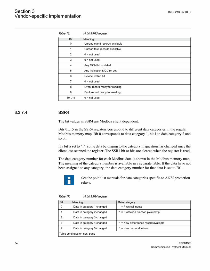
Table 16: 16 bit SSR3 register
Bit Meaning0 Unread event records available
1 Unread fault records available
2 0 = not used
3 0 = not used
4 Any MOM bit updated
5 Any indication MCD bit set
6 Device restart bit
7 0 = not used
8 Event record ready for reading
9 Fault record ready for reading
10...15 0 = not used
3.3.7.4 SSR4
The bit values in SSR4 are Modbus client dependent.
Bits 0...15 in the SSR4 registers correspond to different data categories in the regularModbus memory map. Bit 0 corresponds to data category 1, bit 1 to data category 2 andso on.
If a bit is set to "1", some data belonging to the category in question has changed since theclient last scanned the register. The SSR4 bit or bits are cleared when the register is read.
The data category number for each Modbus data is shown in the Modbus memory map.The meaning of the category number is available in a separate table. If the data have notbeen assigned to any category, the data category number for that data is set to "0".
See the point list manuals for data categories specific to ANSI protectionrelays.
Table 17: 16 bit SSR4 register
Bit Meaning Data category0 Data in category 1 changed 1 = Physical inputs
1 Data in category 2 changed 1 = Protection function pickup/trip
2 Data in category 3 changed
3 Data in category 4 changed 1 = New disturbance record available
4 Data in category 5 changed 1 = New demand values
Table continues on next page
Section 3 1MRS240047-IB CVendor-specific implementation
34 REF615RCommunication Protocol Manual

Bit Meaning Data category5 Data in category 6 changed 1 = New peak demand values
6 Data in category 7 changed
7 Data in category 8 changed 1 = Physical outputs
8 Data in category 9 changed 1 = New minimum demand value
9 Data in category 10 changed 1 = Warnings
10 Data in category 11 changed 1 = RMS, load current changed
11 Data in category 12 changed 1 = Other analog value changed
12 Data in category 13 changed 1= New fault records
13 Data in category 14 changed 1 = Alarms
14 Data in category 15 changed
15 Data in category 16 changed
3.3.7.5 SSR5
SSR5 is a device alive counter. SSR5 simply counts upwards from 0 to 65535 and thenstarts over. The meaning of this register is to assure that the device is actually operating.
3.3.7.6 SSR6
SSR6 is a last command register. This client dependent SSR6 register shows the result ofa specific client's last write attempt. This is especially useful if the exception code 03appears or if the command initiates a secured control operation. The client will only seeits own results, not the results of other clients. A client with no write authority will receivea 0x0000 value response when reading this register.
Table 18: 16 bit SSR6 register
ClientCmdSEQNo Cmd State Resp Type CMDResultCode15 14 13 12 11 10 9 8 7 6 5 4 3 2 1 0
ClientCmdSEQNo
Counts the client's control operations from 0000...1111, that is 0...15, and then starts over.
CmdState
00 = No write command has ever been issued by this client
01 = Command in progress
1MRS240047-IB C Section 3Vendor-specific implementation
REF615R 35Communication Protocol Manual

11 = Response Ready
RespType
01 = Unsecured control response
10 = Secured control response
11 = Modbus 03 exception response valid. CMDResultCode is in this case 0. The reasonfor the 03 exception is an invalid written value.
Table 19: CMDResultCode
Code Meaning0 OK
201 Device in local mode
202 Control operation reserved by another client
203 Select-timeout or Execute/Cancel without select
204 Control operation internally blocked
205 Control operation timed out
250 Other reason
3.3.8 User-definable data
There can be several reasons for defining UD data. For example, the user may want torepack a limited amount of important data into sequential addresses and thereafter onlyscan this smaller set of data. Especially with serial links, this saves bandwidth andimproves response times.
User-definable register can be used if more advanced rescaling and re-manipulating of theregular Modbus register is needed.
3.3.8.1 User definable registers
The Modbus registers 40001 to 40127 are reserved for user definable registers (UDR).Almost any regular register data in the Modbus memory map can be made to appear as aregister copy in this UDR memory area. The regular Modbus source register is not movedaway from its original location and thus it can be read also from the original location.
3.3.8.2 User definable bits
The binary signals originally mapped in 0x, 1x or 4x area can be remapped to UDR registerspace as a 4x register packed with binary signals. Almost any regular bit data in theModbus memory map can be made to appear as a bit data copy in this UDB memory area.
Section 3 1MRS240047-IB CVendor-specific implementation
36 REF615RCommunication Protocol Manual

The regular Modbus source bit data are not moved away from their original location andthus they can be read also from the original location.
Using the configuration tool, the digital signals can be flexibly picked andpacked in the UDR space. These digital signals do not have to be packedin the same way as in the original 4x registers before.
3.3.8.3 Data exceptions
Some exceptions exist for the Modbus source data concerning the UD mapping.
• None of the system status registers or fixed register structures can appear in the UDarea.
• UD registers/bits themselves cannot act as source data for other UD data.• Modbus source data can only be attached to one UD location.
3.3.8.4 Data properties
The UD data inherits all properties from the source data. This applies to:
• The memory areas on which the source data are located• Data pre-scaling in case of registers
3.3.8.5 Unmapped data locations
It is possible to partially scan unmapped register or bit locations, also known as gaps. Noexception responses are generated. The unmapped locations always return data value 0.
3.3.8.6 UDR data configuration
UDR definitions can be created using the Communication Management tool in PCM600.
3.3.8.7 UDR register value manipulation
UDR values are initially copied from the source register. Thereafter the followingmanipulations can be applied to the UDR value.
1MRS240047-IB C Section 3Vendor-specific implementation
REF615R 37Communication Protocol Manual

• Additional rescaling of the source data value.• Swapping high/low words within the 32 bit register types.• Changing the saturation points of the UDR values, that is, the bit-length of the source
value can be redefined. Also the justification of the redefined bits within the Modbusregister can be defined.
• Swapping high/low bytes within the 16 bit register types.
Table 20: UDR scaling alternatives
Scaling alternative Setting DescriptionNo scaling No change is made to the sourceValue
Ratio scaling UDRScaleArg1 = Min in
Uses all 4 scaling argumentsUDRScaleArg1...UDRScaleArg4.
UDRScaleArg2 = Max in
UDRScaleArg3 = Min out
UDRScaleArg4 = Max out
Multiplicativescaling
UDRScaleArg1 =Multiplicand Uses the argument UDRScaleArg1 (Min in)
Divisior scaling UDRScaleArg1 = Divisor Uses the argument UDRScaleArg1 (Min in)
Ratio scaling Operation
The sourceValue is to be checked for saturation. If it is less than Min in, the UDR resultvalue is equal to Min out. If it is greater than Max in, the UDR result value is Max out.Otherwise the UDR result value is calculated as
• X = (MaxOut-MinOut)/(MaxIn-MinIn)• UDR_ResultValue = X × sourceValue + (MinOut - X × MinIn)
Multiplicative scaling Operation
UDR_resultValue = sourceValue × multiplicand
Divisior scaling Operation
UDR_resultValue = sourceValue/Divisor
3.3.9 Event records
The protection relay creates a Modbus event record when a momentary digital input bitchanges its value. The protection relay then stores the changed Modbus bit location andvalue into the Modbus event record buffer. The event time tag is also stored into therecord. The time tag includes a full time stamp from a year down to milliseconds.
Section 3 1MRS240047-IB CVendor-specific implementation
38 REF615RCommunication Protocol Manual

Modbus event generation on/off is selectable for each individual momentary bit in theModbus memory map. It is possible to define whether events are to be generated from therising edge- or both edges' transitions of the momentary bit.
Modbus events can also be generated from selected Modbus registers. This concernsregisters containing status information. In this case events would be generated each timethe register's integer value changes.
The size of the protection relay's internal Modbus event record buffer is 500 events. The500 latest events are at any time readable from the protection relay. When the Modbusevent record buffer becomes full, the protection relay overwrites the oldest event recordsin the buffer.
Multiple clients supportSeveral Modbus clients can independently of one another read out Modbus event recordsfrom the protection relay. The Modbus event buffer keeps track of where in the eventbuffer the different clients are reading at the moment. Clients are identified either by theserial port from where the requests are issued or by the client's IP address in the TCP/IPnetwork. Up to 25 different IP addresses, belonging to both registered and unregisteredModbus clients, can be memorized by the protection relay. The maximum number ofModbus clients which can simultaneously access the server is five.
3.3.9.1 Single event record structure
See Modbus ANSI point list manuals for specific event record structure mappings.
Table 21: Event record structure
Address Register Values Comment4xxxx+1 Event selection 1…5 and -1…-499 Write register
4xxxx+2 TimeStamp (Year)
4xxxx+3 TimeStamp (Month)
4xxxx+4 TimeStamp (Day)
4xxxx+5 TimeStamp (Hour)
4xxxx+6 TimeStamp (Minute)
4xxxx+7 TimeStamp (Second)
4xxxx+8 TimeStamp (Milliseconds)
4xxxx+9 Sequence number 0…65535
4xxxx+10 Lower word of value Modbus data valueValue of the object which raisesthe event
4xxxx+11 Higher word of the value
4xxxx+12 Area of the register 0 = 0x; 1=1x; 4=4x
Register of the object of whichthe value change raises theModbus event.
4xxxx+13 Register address
1MRS240047-IB C Section 3Vendor-specific implementation
REF615R 39Communication Protocol Manual
3.3.9.2 Single event record reading
As long as there are unread Modbus events available for the Modbus client in question, bit0 of Modbus SSR3 register remains "1".
Events are read in two steps. First, the client writes a selection code to the Event selectionregister. The selection code defines the type of read operation that the client wants toperform. The selected event record is loaded by the protection relay into the following 12registers. Second, the client reads out the 12 registers in one multiple register readoperation.
Event records can be read by using two commands, function 6 for the writeoperation and function 3 for the read operation, or by using function 23that includes write and read operations in the same transaction.
If event records are read by using two commands, the positiveconfirmation to the write select operation tells the client that an eventrecord has been loaded for reading. Another way to detect the positiveconfirmation is by monitoring the state of SSR3 bit 8.
Selection code 1: Reading the oldest stored recordSelection code 1 always forces the event reading to go back to the oldest event in theModbus event buffer.
Selection code 2: Reading the next stored recordSelection code 2 always brings up the next record read from the event buffer.
Selection code -1...-499A negative selection code, that is a 16 bit two's complement value, defines how manyrecords backwards from the newest event the event record reading is to be moved. Forexample, the ten latest events could be read out at any time by first selecting -10, readingout the event and then continuing with the selection code 1 to read out the nine additionalevent records. There can be 500 event records altogether.
Selection code 3: Reading the oldest unread recordWhen writing the selection code 3, the protection relay first checks the client. If the clienthas read events before, the protection relay knows which internal event has been sent tothis specific client during the last reading. The protection relay then loads the next event,that is the oldest unread, into the next 12 registers. If this is the first time the client readsevents from the protection relay, the oldest event of the Modbus event buffer is loaded into
Section 3 1MRS240047-IB CVendor-specific implementation
40 REF615RCommunication Protocol Manual

the 12 event read registers. If the client has read all the events from protection relay, thelatest event of the Modbus event buffer is loaded into the 12 event read registers.
Selection code 4: Resetting SSR3 bit 8The write selection 4 is not followed by a read operation. The selection code only resetsthe bit 8 in SSR3.
Selection code 5: Resetting the event read pointerThe write selection 5 is not followed by a read operation. The selection 5 means that thereare no unread records in the Modbus event buffer left for the client in question, that is, thebuffer is cleared. The next new event that is logged into the Modbus event buffer becomesthe first unread record for this specific client.
If event records are read by using two commands, the client can re-read the12 event record registers as many times as it wants. As long as no newselection write operation is performed, the contents of the 12 event recordregisters are not changed.
3.3.9.3 Other event record registers
Sequence numberEvery Modbus event record is given a sequence number. The sequence number runs from1 to 65535 and then rolls over to 1 again. The client can check that the sequence numbersof the recorded data are sequential. During the event buffer overflow the client can noticea jump in the sequence numbers when some event records are lost. The gap between thenew and the previous sequence number reveals exactly how many event records have beenlost.
Time stamp registersTime stamp is either in local time or UTC time. In factory default, it is in local time.
One word register holds one time stamp element.
3.3.9.4 Multiple event records reading
It is possible to read out up to 10 sequential event records in one event select/readtransaction. The number of sequential event records to be returned for reading shall bewritten to the Num of records register in front of the selection register. This number canbe written once or it can be rewritten for each select/read transaction. If this number isnever written, only one event record is returned.
1MRS240047-IB C Section 3Vendor-specific implementation
REF615R 41Communication Protocol Manual

If the Modbus client requests multiple event records, the returned records should also beread out by the client. One record consists of 12 registers, two records of 24 registers andso on. The read length must thus be adjusted depending on the number of recordsrequested.
The selection/read operation is otherwise exactly similar to the single-record read case.The next records to be returned always continues from the last record in the previous readoperation.
Reading out more event records than are available in the internal eventbufferThe requested amount of event records is always returned for reading. For example, if 10event records are requested, but the protection relay only contains five event records, thelast valid event record is repeated (duplicated) in the last five event records returned. Theeasiest way to detect the duplication is to check the sequence number of the event records.The sequence numbers remain similar to the duplicated event records.
Extended event record structureTable 22: Extended event record structure with the maximum of 10 event records
Address1) Register Values Comment
4xxxx Number of record 1…10 Write: Number of eventstructures
4xxxx+1 Selection Write: Selection code
4xxxx+2 TimeStamp (Year) Event record 1
4xxxx+3 TimeStamp (Month)
4xxxx+4 TimeStamp (Day)
4xxxx+5 TimeStamp (Hour)
4xxxx+6 TimeStamp (Minute)
4xxxx+7 TimeStamp (Second)
4xxxx+8 TimeStamp (Milliseconds)
4xxxx+9 Sequence number
4xxxx+10 Lower word of value
4xxxx+11 Higher word of the value
4xxxx+12 Area of the register
4xxxx+13 Register address
4xxxx+14 TimeStamp (Year) Event record 2
:
4xxxx+25 Register address
Table continues on next page
Section 3 1MRS240047-IB CVendor-specific implementation
42 REF615RCommunication Protocol Manual

Address1) Register Values Comment
4xxxx+26 TimeStamp (Year) Event record 3
:
4xxxx+37 Register address
4xxxx+38 TimeStamp (Year) Event record 4
:
4xxxx+49 Register address
4xxxx+50 TimeStamp (Year) Event record 5
:
4xxxx+61 Register address
4xxxx+62 TimeStamp (Year) Event record 6
:
4xxxx+73 Register address
4xxxx+74 TimeStamp (Year) Event record 7
:
4xxxx+85 Register address
4xxxx+86 TimeStamp (Year) Event record 8
:
4xxxx+97 Register address
4xxxx+98 TimeStamp (Year) Event record 9
:
4xxxx+109 Register address
4xxxx+110 TimeStamp (Year) Event record 10
:
4xxxx+121 Register address
1) See REF615R Modbus point list manual for specific event record structure mapping.
3.3.10 Fault records
A fault record is created by the protection relay as a set of registrations during a detectedfault period. The registration includes the selected peak values and the global durationvalue of the protection stages, the time of recording and a sequence number for the faultrecord.
The size of the protection relay's internal Modbus fault record buffer is 100 records. The100 latest fault records are at any time readable from the protection relay. The Modbusfault record is Modbus dependent and the data organization and buffer size differ from theprotection relay's initial system level registrations. When the Modbus fault record bufferbecomes full, the protection relay overwrites the oldest records in the buffer.
1MRS240047-IB C Section 3Vendor-specific implementation
REF615R 43Communication Protocol Manual

Multiple clients supportSeveral Modbus clients can independently of one another read out the Modbus faultrecords from the protection relay. The Modbus fault record buffer keeps track of where inthe buffer the different clients are reading at the moment. Clients are identified either bythe serial port from where the requests are issued or by the client's IP address in the TCP/IPnetwork.
3.3.10.1 Fault record structure
The protection relay's fault record structure consists of a fixed header part and anapplication data part. The application data part is always protection relay type specific.The whole fault record including the protection relay specific application data part isfound in the Modbus point list manual for this specific protection relay.
Table 23: Header part of the record structure
Address1) Register Values Comment
4xxxx Fault records selection 1…5 and -1…-99 Write register
4xxxx+1 Fault element type
4xxxx+2 Spare
4xxxx+3 Fault sequence number 0…65535
4xxxx+4 Year
4xxxx+5 Month
4xxxx+6 Day
4xxxx+7 Hours
4xxxx+8 Minutes
4xxxx+9 Seconds
4xxxx+10 Hundredths of seconds
4xxxx+11 From this location onwardsstarts the fault recordapplication data.
1) See REF615R Modbus ANSI point list manual for a specific event record.
Fault record application data partThe data in the application section are protection relay type dependent. The description ofthe data is found in the Modbus fault record section of the Modbus point list manual forthis specific protection relay.
Section 3 1MRS240047-IB CVendor-specific implementation
44 REF615RCommunication Protocol Manual

3.3.10.2 Fault record reading
As long as there are unread fault records available for the Modbus client in question, bit1 of the Modbus SSR3 register remains "1".
The fault record reading is done in two steps. First, the client writes a selection code to theFault record selection register. The selection code defines the type of read operation thatthe client wants to do. The selected fault record is loaded by the protection relay into thefollowing N registers (4xxxx-NNNN). See Modbus ANSI point list manual for specificfault record structure mapping. Second, the client reads out these registers in one multipleregister read operation.
The fault records can be read by using two commands, the function 6 forthe write operation and the function 3 for the read operation, or by usingthe function 23 that includes write and read operations in the sametransaction.
If the fault records are read by using two commands, the positiveconfirmation to the write select operation tells the client that a fault recordhas been loaded for reading. Another way to detect the positiveconfirmation is by monitoring the state of SSR3 bit 9.
Fault record structure lengthSince the application data part is protection relay type dependent, the length of the faultrecord structures vary in different types of protection relays. A client can read out moreModbus registers than are actually coded in one structure when reading out the datastructures. The maximum read amount is 128 Modbus registers. The registers not beingmapped contain the value 0. The Modbus protocol will give an exception response if theclient tries to read out too few registers from the fault record structure.
Selection code 1: Reading the oldest stored recordThe selection code 1 always forces the fault record reading to go back to the oldest faultrecord stored in the buffer.
Selection code 2: Reading the next stored recordSelection code 2 always brings up the next record read from the fault record buffer.
Selection code -1...-99A negative selection code, that is a 16 bit two's complement value, defines how manyrecords backwards from the newest fault record the reading is to be moved. For example,
1MRS240047-IB C Section 3Vendor-specific implementation
REF615R 45Communication Protocol Manual

the ten latest fault records can be read out at any time by first selecting -10, reading out therecord and then continuing with the selection code 1 to read out the nine additional records
Selection code 3: Reading the oldest unread recordWhen writing the selection code 3, the protection relay first checks the client. If the clienthas been reading fault records before, the protection relay knows which internal faultrecord has been sent to this specific client during the last reading. The protection relay thenloads the next fault record, that is the oldest unread. If all the fault records have been read,writing selection 3 loads the last fault record for this client to read.
Selection code 4: Resetting SSR3 bit 9The write selection 4 is not followed by any read operation. The selection code only resetsbit 9 in SSR3.
Selection code 5: Resetting the fault record read pointerThe write selection code 5 is not followed by a read operation. The selection 5 means thatthere are no unread records in the Modbus fault record buffer left for the client in question.The next new fault record that is logged into the Modbus fault record buffer becomes thefirst unread record for this specific client.
If the fault records are read by using two commands, the client can re-readthe given fault record registers as many times as it wants. As long as nonew selection write operation is performed, the contents of the fault recordregisters are not changed.
3.3.10.3 Other fault record registers
Sequence numberEvery fault record is given a sequence number. The sequence number runs from 1 to 65535and then rolls over to one again. The client can check that the sequence numbers of therecorded data are sequential. During the fault record buffer overflow the client can noticea jump in the sequence numbers when some fault records are lost. The gap between thenew and the previous sequence number reveals exactly how many records have been lost.
Time stamp registersTime stamp is either in local time or UTC time. In factory default, it is in local time.
One word register holds one time stamp element.
Section 3 1MRS240047-IB CVendor-specific implementation
46 REF615RCommunication Protocol Manual

3.3.11 Parameter setting group selection
The active parameter setting group can be changed by writing the new setting groupnumber to 4X register. See Modbus ANSI point list manual for specific mapping. See theprotection relay documentation for the number of available setting groups. Exceptionresponse 3 is given if the written value is out of range or the setting group changing isblocked.
3.3.12 Time synchronization
The real-time clock inside the protection relay runs in UTC time. However, the local timeis also known by the protection relay through the time parameter settings. With Modbusthe protection relay time can be viewed and set either in local time or UTC time.
Two identical time structures are available in the Modbus memory map: the protectionrelay's local time and the internal UTC time.
Time synchronization can be given either to the local time structure or to the UTC timestructure.
The protection relay accepts Modbus time synchronization only if theSynch source setting is set to "Modbus". The parameter can be set viaConfiguration/Time/Synchronization/Synch source.
3.3.12.1 Real-time clock structure
Table 24: Modbus real-time clock structure
Modbus address1) Register contents ValuesLocal Time UTC Time
4xxxx 4xxxx + 19 Control register 0...2
4xxxx + 1 4xxxx + 10 Year 2000...9999
4xxxx + 2 4xxxx + 11 Month 1...12
4xxxx + 3 4xxxx + 12 Day 1...31
4xxxx + 4 4xxxx + 13 Hour 0...23
4xxxx + 5 4xxxx + 14 Minutes 0...59
4xxxx + 6 4xxxx + 15 Seconds 0...59
4xxxx + 7 4xxxx + 16 Milliseconds 0...999
1) See Modbus ANSI point list manual for specific event record structure mapping.
1MRS240047-IB C Section 3Vendor-specific implementation
REF615R 47Communication Protocol Manual

3.3.12.2 Writing to real-time structures
The Modbus time synchronization can be done in several ways. Over the serial interface,the host's synchronization write can be given with the Modbus broadcast address "0".Thus, all protection relays in the same serial network can be synchronized at the sametime.
Method 1: Synchronization in one stepThe real-time clock structure registers should be written in one multiple registers presetrequest (function 16) by a Modbus TCP/IP client or by a serial interface master. Theprotection relay's Modbus address or the Modbus broadcast address can be used with theserial interface. If the clock is written in one step, the write value of the control register isnot checked by the protection relay.
Method 2: Synchronization in three steps1. The client reserves the time synchronization by writing value "1" to the control
register. If necessary, check that the reservation value is zero at the beginning. If thetime synchronization writing is already reserved by another client, the protectionrelay returns the exception response 03.
2. The client writes the time structure to the protection relay. This can be done in onetransaction or alternatively each register can be written separately.
3. The client sets the clock by writing "2" into the control register. When the value "2"is written, the timesync registers are latched onto the protection relay's internal clockand the reservation of the control register is released.
The Modbus broadcast address cannot be used with the synchronizationmethod 2.
There is an internal timeout for the clock setting. The time synchronization reservation isreleased if the clock is not set within two minutes. The client can abort the timesynchronization at any time by writing "0" into the control register. In that case the real-time clock is not set at all.
Other Modbus clients can read the currently running real-time clock even if the timewriting is reserved by another client.
3.3.13 Device information
The device information of the protection relay can be read from the Modbus registers.
Section 3 1MRS240047-IB CVendor-specific implementation
48 REF615RCommunication Protocol Manual

If the information data are in practice shorter, the trailing registers in theresponse are filled with the value "0".
The Modbus device information is based on the internal IEC 61850 device informationmodel of the protection relay. All internal descriptions are coded as ASCII strings. TheModbus device information ASCII string includes the information from the protectionrelay.
• Protection relay model (max. 12 characters)• Protection relay type (max. 6 characters)• Protection relay serial number (max. 12 characters)• Protection relay location information (max. 34 characters)• CPU card SW and HW revision numbers• Protection relay bay name (max. 20 characters)• HMI card SW and HW revision numbers• Slot 0 (X130) card SW and HW revision numbers• Slot 2 (X110-BIO) card SW and HW revision numbers• Slot 3 (X100-PSM) card SW and HW revision numbers• Slot 2 (X110-BIO-H) card SW and HW revision numbers• Slot 3 (X100-PSM High speed) card SW and HW revision numbers
The protection relay does not need to contain cards in all slots nor does aspecific card need to include a CPU. Slot 2 and Slot 3 can only containeither high speed card or standard speed card depending on the deviceconfiguration. As a result, the registers mapped with the valid cards canshow the values, the other ones remain as 0. The SW revision informationis simply omitted from the information string.
3.3.13.1 ASCII character coding
Table 25: The 8 bit ASCII character coding in the Modbus registers
Modbus register ASCII characterRegister 1 High byte = ASCII character 1
Register 1 Low byte = ASCII character 2
Register 2 High byte = ASCII character 3
: :
1MRS240047-IB C Section 3Vendor-specific implementation
REF615R 49Communication Protocol Manual

3.3.13.2 ASCII string syntax
SyntaxC(model;type;serialNo;location;swRev;hwRev)H(swRev;hwRev)0(swRev;hwRev)1(swRev;hwRev)2(swRev;hwRev)3(swRev;hwRev)4(swRev;HwRev)• Parenthesis and semicolon ASCII characters are used as delimiters inside the string.• Section C(...) contains protection relay information and CPU version
information.• Section H(...) contains version information of the LHMI card.• Sections 0(... ) to 4(...) contain version information of the additional HW
cards (slots 0...4).• If an additional card does not include any version information, it is signaled with
a ”-” (minus) character in the swRev field. If both swRev and hwRev are signalledwith ”-” signs, the card in question does not exist in the protection relay.
Example of an identification string could beC(REF615R;FE01;1VHR123456R2;feeder15.12;1.6;2.0)H(1.2;3.1)0(-;-)1(-;1.1)2(-;1.0)3(-;1.1)4(-;2.0)
The data within the C section is restricted to certain maximum lengths. For example, theuser-definable protection relay location is here restricted to a maximum of 34 characters.If the protection relay location information on system level contains more characters, onlythe 34 first characters are displayed.
3.3.14 Reset time structure
The time and cause of the protection relay's last reset are stored into this structure. Thereset time is taken directly from the protection relay's RTC at the startup. The clock mightnot be accurate and the data can be corrupted.
Table 26: Reset time structure
Address1) Register Values Comment
4xxxx TimeStamp(Year,Month)
High byte:year, lowbyte:month
4xxxx + 1 TimeStamp (Day,Hour) High byte:day, lowbyte:hour
4xxxx + 2 TimeStamp (Min,Sec) High byte:min, lowbyte:seconds
Table continues on next page
Section 3 1MRS240047-IB CVendor-specific implementation
50 REF615RCommunication Protocol Manual

Address1) Register Values Comment
4xxxx + 3 TimeStamp(Milliseconds)
Word: milliseconds
4xxxx + 4 Time Quality See Time quality table
4xxxx + 5 Cause of reset 1 = Power reset
2 = Watchdog reset
3 = Warm reset
1) See Modbus ANSI point list manual for specific event record structure mapping.
Table 27: Time quality
Bit Meaning Values15 Time format 0 = Local time
1 = UTC time
14 Time source 0 = Internal (RTC)
13 RTC not synchronized 0 = RTC synchronized
1 = Not synchronized
12 RTC Failure 0 = RTC OK
1 = RTC failure
11...0 Not used 0
3.3.15 Accessing of non-protocol-mapped data
The protection relay application includes a number of general-purpose I/O data. Bydefault, these data are mapped to this protocol. See the point list manual for the exactmappings.
The general-purpose objects can be connected to any internal object in the protection relayconfiguration application using the Application Configuration or Signal Matrix tool. Thisgives additional opportunities for the protocols.
Example 1Due to security reasons, protocols do not contain mappings for the direct control ofphysical outputs. This way, the client cannot accidentally write a change to a physicaloutput.
It is possible to connect general-purpose outputs to physical outputs using the ApplicationConfiguration tool. The general-purpose output can also be controlled from the protocol.
1MRS240047-IB C Section 3Vendor-specific implementation
REF615R 51Communication Protocol Manual

Example 2The legacy protocol default mappings are a selection of the most important signalsproduced by the IEC 61850-based protection relay applications. The manufacturer’sselection of important signals may not always serve every customer.
Any non-protocol-mapped internal signal can be freely connected to a general-purposeinput object via the Application Configuration tool. This object can then be accessed bythe legacy protocol as regular protocol application data.
Example 3The basic IEC 61850 application model of the protection relay produces a great amountof information. In some cases, this is more than what is feasible to transport through alegacy protocol. Via the PCM600/Communication Management tools, unnecessary dataobjects can be excluded from the legacy protocol.
However, in some cases a better solution is to OR together several internal signals into onegeneral signal. This OR output can be connected to a general-purpose input and accessedby the legacy protocol as regular protocol application data.
Section 3 1MRS240047-IB CVendor-specific implementation
52 REF615RCommunication Protocol Manual

Section 4 Modbus parameters and diagnostics
4.1 Parameter list
The Modbus parameters can be accessed with PCM600 or via the LHMI pathConfiguration/Communication/Modbus.
Table 28: Modbus settings
Parameter Values (Range) Unit Step Default DescriptionSerial port 1 0=Not in use
1=COM 12=COM 2
0=Not in use COM port for Serial interface 1
Parity 1 0=none1=odd2=even
2=even Parity for Serial interface 1
Address 1 1...255 1 Modbus unit address on Serial interface 1
Link mode 1 1=RTU2=ASCII
1=RTU Modbus link mode on Serial interface 1
Start delay 1 0...20 char 4 Start frame delay in chars on Serial interface 1
End delay 1 0...20 char 3 End frame delay in chars on Serial interface 1
Serial port 2 0=Not in use1=COM 12=COM 2
0=Not in use COM port for Serial interface 2
Parity 2 0=none1=odd2=even
2=even Parity for Serial interface 2
Address 2 1...255 2 Modbus unit address on Serial interface 2
Link mode 2 1=RTU2=ASCII
1=RTU Modbus link mode on Serial interface 2
Start delay 2 0...20 4 Start frame delay in chars on Serial interface 2
End delay 2 0...20 3 End frame delay in chars on Serial interface 2
MaxTCPClients 0...5 5 Maximum number of Modbus TCP/IP clients
TCPWriteAuthority 0=No clients1=Reg. clients2=All clients
2=All clients Write authority setting for Modbus TCP/IPclients
EventID 0=Address1=UID
0=Address Event ID selection
TimeFormat 0=UTC1=Local
1=Local Time format for Modbus time stamps
Table continues on next page
1MRS240047-IB C Section 4Modbus parameters and diagnostics
REF615R 53Communication Protocol Manual

Parameter Values (Range) Unit Step Default DescriptionClientIP1 000.000.000.000 Modbus Registered Client 1
ClientIP2 000.000.000.000 Modbus Registered Client 2
ClientIP3 000.000.000.000 Modbus Registered Client 3
ClientIP4 000.000.000.000 Modbus Registered Client 4
ClientIP5 000.000.000.000 Modbus Registered Client 5
CtlStructPWd1 **** Password for Modbus control struct 11)
CtlStructPWd2 **** Password for Modbus control struct 2
CtlStructPWd3 **** Password for Modbus control struct 3
CtlStructPWd4 **** Password for Modbus control struct 4
CtlStructPWd5 **** Password for Modbus control struct 5
CtlStructPWd6 **** Password for Modbus control struct 6
CtlStructPWd7 **** Password for Modbus control struct 7
CtlStructPWd8 **** Password for Modbus control struct 8
1) The amount of available control structures may vary depending on the protection relay type
4.2 Monitored data
The Modbus serial monitored data can be accessed with the Parameter Setting tool inPCM600 or via the LHMI path Monitoring/Communication/Modbus/Serial.
Table 29: Modbus serial
Parameter Values (range) Description
Received frames N1) 0...2147483648 Received Modbus frames by instance N
Transmitted frames N 0...2147483648 Transmitted Modbus frames by instance N
Cksm Err N 0...2147483648 Checksum errors detected by instance N
Transmitted Exec A N 0...2147483648 Transmitted exception responses 1 and 2 by instance N
Transmitted Exec B N 0...2147483648 Transmitted exception responses 3 by instance N
Status N True, False Status of communication, instance NReset of diagnostic counters instance N
1) N = instance number 1, 2...
The Modbus Ethernet monitored data can be accessed with the Parameter Setting tool inPCM600 or via the LHMI path Monitoring/Communication/Modbus/Ethernet.
Section 4 1MRS240047-IB CModbus parameters and diagnostics
54 REF615RCommunication Protocol Manual

Table 30: Modbus TCP/IP
Parameter Values (range) Description
Received frames N1) 0...2147483648 Received Modbus frames by instance N
Transmitted frames N 0...2147483648 Transmitted Modbus frames by instance N
Transmitted Exec A N 0...2147483648 Transmitted exception responses 1 and 2 by instance N
Transmitted Exec B N 0...2147483648 Transmitted exception responses 3 by instance N.
Cn Rejects No socket 0...2147483648 Connection rejections due to no free sockets
Cn Rejects Not reg 0...2147483648 Connection rejections due to not registered client IP.
Status N True, False Status of communication, instance NReset of diagnostic counters instance N
1) N = instance number 1, 2...
1MRS240047-IB C Section 4Modbus parameters and diagnostics
REF615R 55Communication Protocol Manual

56

Section 5 Glossary
ANSI American National Standards InstituteASCII American Standard Code for Information InterchangeCPU Central processing unitCT Current transformerData set The content basis for reporting and logging containing
references to the data and data attribute valuesDPC Double-point controlDPS Double-point statusEMC Electromagnetic compatibilityEthernet A standard for connecting a family of frame-based computer
networking technologies into a LANHMI Human-machine interfaceHW HardwareIEC 61850 International standard for substation communication and
modelingIP address A set of four numbers between 0 and 255, separated by
periods. Each server connected to the Internet is assigned aunique IP address that specifies the location for the TCP/IPprotocol.
LHMI Local human-machine interfaceLSB Least significant bitMCD Momentary change detectModbus A serial communication protocol developed by the Modicon
company in 1979. Originally used for communication inPLCs and RTU devices.
Modbus ASCII Link mode using 7-bit ASCII charactersModbus memorymap
Allocation of accessible protocol data
Modbus RTU Link mode using 8-bit binary characters
1MRS240047-IB C Section 5Glossary
REF615R 57Communication Protocol Manual
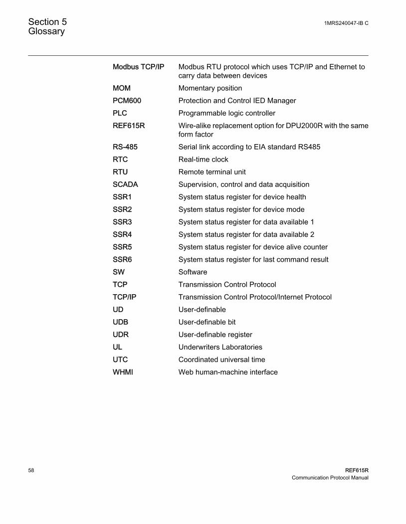
Modbus TCP/IP Modbus RTU protocol which uses TCP/IP and Ethernet tocarry data between devices
MOM Momentary positionPCM600 Protection and Control IED ManagerPLC Programmable logic controllerREF615R Wire-alike replacement option for DPU2000R with the same
form factorRS-485 Serial link according to EIA standard RS485RTC Real-time clockRTU Remote terminal unitSCADA Supervision, control and data acquisitionSSR1 System status register for device healthSSR2 System status register for device modeSSR3 System status register for data available 1SSR4 System status register for data available 2SSR5 System status register for device alive counterSSR6 System status register for last command resultSW SoftwareTCP Transmission Control ProtocolTCP/IP Transmission Control Protocol/Internet ProtocolUD User-definableUDB User-definable bitUDR User-definable registerUL Underwriters LaboratoriesUTC Coordinated universal timeWHMI Web human-machine interface
Section 5 1MRS240047-IB CGlossary
58 REF615RCommunication Protocol Manual

59


ABB Distribution SolutionsDistribution AutomationP.O. Box 699FI-65101 VAASA, FinlandPhone +358 10 22 11
ABB Inc.655 Century PointLake Mary, FL 32746, USAPhone +1-800-222 1946
www.abb.com/mediumvoltagewww.abb.com/relionwww.abb.com/substationautomation
—
© Copyright 2019 ABB. All rights reserved. 1MR
S24
00
47-
IB C