manual de usuario granalladora (2).pdf
TRANSCRIPT
7/30/2019 MANUAL DE USUARIO GRANALLADORA (2).pdf
http://slidepdf.com/reader/full/manual-de-usuario-granalladora-2pdf 1/240
LLhee l a b r a t o r••• •••• GROUP
Wheelabrator Group
1219 Corporate Drive
Burlington, Ontario L7L 5V5
T: 905-319-7930
T: 800-845-8508
F: 905-319-7561
F: 800-571-5637
vmw.wheelabratorgroup.com
WARRANTY 3463
Gunderson-Gimsa
Purchase Order Number GGOS747-1
Seller warrants that the equipment described herein will be free from defects in material
and workmanship for a period of twelve (12) months from delivery ("Warranty Period").
Ifwithin the Warranty Period Seller receives written notice promptly after the discovery
of any defect in the material or workmanship Seller shall correct each such defect FOB
point of manufacture. Seller shall undertake its warranty obligation of repair,
replacement within a reasonable time of receiving actual notice ofthe warranty defect.
Seller shall be fully compensated for expenses of travel and for job time (at Seller's thenprevailing per diem rates for straight time and premium time, as applicable) of its service
representatives who inspect warranty claims that are not warranty issues. Buyer shall
issue a purchase order for these expenses prior to Seller's representatives arrival on site
Purchaser has no right to and may not backcharge Seller for warranty claims without prior
approval. Normal wear parts and labor are not included. The liability of Seller to
Purchaser/Buyer arising out of or the supplying of the equipment whether under warranty,
tort, contract, negligence, strict liability or otherwise, shall not in any case exceed the cost
of correcting defects in Equipment and l,1ponthe expiration of said warranty, all such
7/30/2019 MANUAL DE USUARIO GRANALLADORA (2).pdf
http://slidepdf.com/reader/full/manual-de-usuario-granalladora-2pdf 2/240
Operation &
Maintenance
ManualLlheelabrator
••••• GROUP
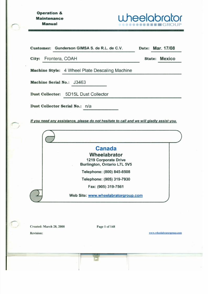
Customer: Gunderson GIMSAS. de R.L. de C.V. Date: Mar. 17/08
City: Frontera, COAH State: Mexico
Machine Style: 4Wheel Plate Descaling Machine
Machine Serial No.: J 3463
Dust Collector: 5D15L Dust Collector
Dust Collector Serial No.: n/a
If you need any assistance, please do not hesitate to call and we will gladly assist you.
7/30/2019 MANUAL DE USUARIO GRANALLADORA (2).pdf
http://slidepdf.com/reader/full/manual-de-usuario-granalladora-2pdf 3/240
Operation &
Maintenance
Manual
u.heelabrator••• GROUP
See 0 1 Int tQduction l i t . . • . • . • . • . • . • . " . . . . . . • . • . • . • . • . • . ' I I • . • . • . • . • . • . • . • . I I I . . . . . . . . . . . . . . • . • . • . • . • . • . 11
I. 2 1ft truetteA GAdWambtg Syfftbols.. •.••. •.•.•.•.•.••..•.•.•.•••••••••. •. .••.1.2
1.2.1 Read! 12
1.2.2 Caution! 12
1.2.3 Warning! 12
1.2.4 Danger! 12
1.2.5 Electrical Hazard! 12
I. 3 lftstmetioAs... 1.2
1.3.1 Reading about Equipment 12
1.3.2 Understanding the Equipment 13
1.3.3 Equipment Operators & Maintenance Personnel Qualifications 13
1.3.4 Warnings & Precautions 13
1.3.5 Receipt of Equipment 13
7/30/2019 MANUAL DE USUARIO GRANALLADORA (2).pdf
http://slidepdf.com/reader/full/manual-de-usuario-granalladora-2pdf 4/240
Operation &
Maintenance
Manualuheelabrator
•••••••• GROUP
3.4.1 Control Panel 22
3.4.2 Electrical Motors 22
3.4.3 Equipment Installation Wiring 23
3.4.4 Equipment SafetyGrounding 23
3.5.1 Installation 24
3.5.1.1 Lift points 24
3.5.1.2 Tipping Hazard 24
3.5.1.3 Equipment Placement 24
3.5.2 Items to bechecked and completed before start-up 25
3 .4 5 ctf t.iCClI ~Oft •.•.•.• .•.•.•.•.•.• •.•.•.•.•.••.•.•.•.• .•.•.•.•.•.• .•.•.• .•.•.•.•.•".. .• .•.•25
3.6.1 Mechanical Do's &Don'ts Items: 26
~.. ~car~.. .. .. lt~
3.7.1 Caution Signs 28
3.7.2 Warning Signs 30
3.7.3 DangerSigns 32
7/30/2019 MANUAL DE USUARIO GRANALLADORA (2).pdf
http://slidepdf.com/reader/full/manual-de-usuario-granalladora-2pdf 5/240
Operation &
Maintenance
Manualu.heelabrator
•• • _GROUP
ec: 0 Ii System " ,. .
~.. •.•.•.•.•.•.•..•.•.•.•.•.•. •.•.•.•. •.•.•. •. •.•.•.•.•.•.•.•.•.•.•. J[
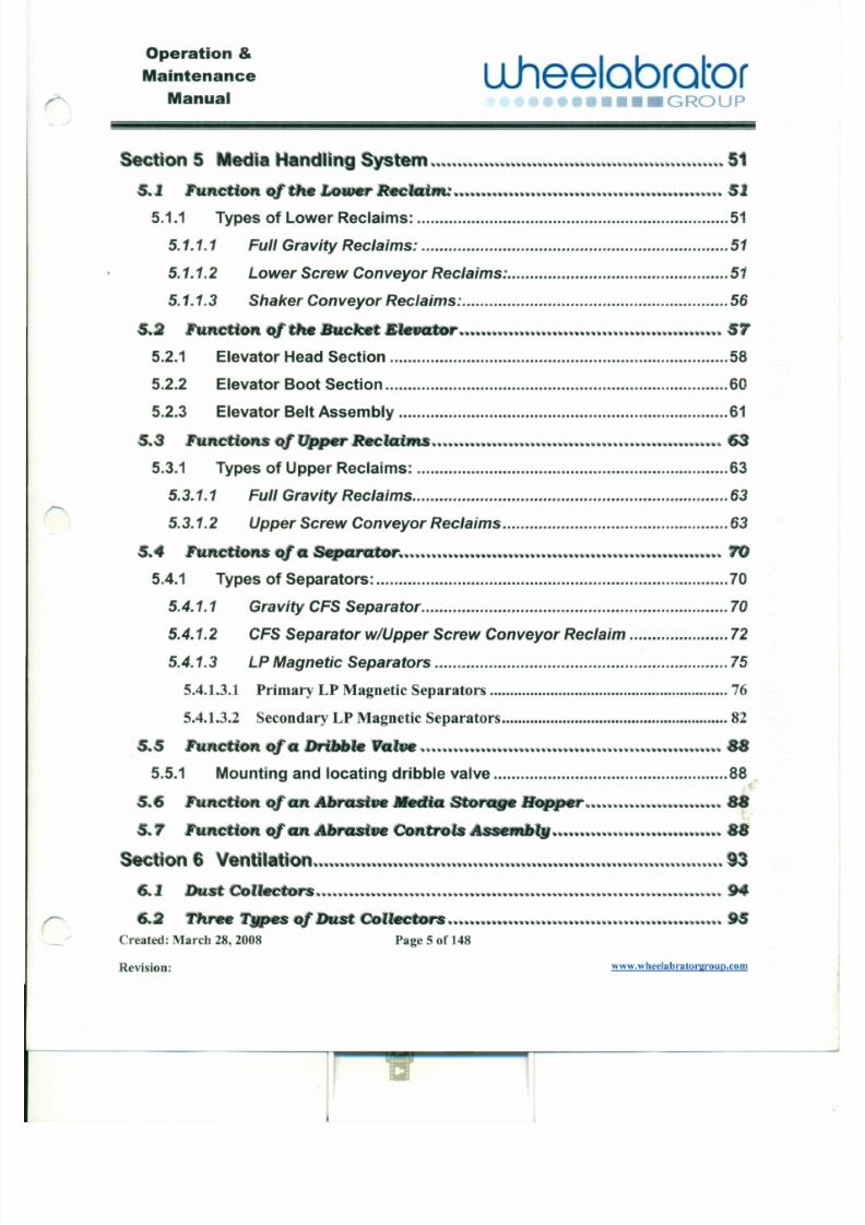
5.1.1 Types of Lower Reclaims: 51
5.1.1.1 Full Gravity Reclaims: 51
5.1.1.2 Lower Screw Conveyor Reclaims: 51
5.1.1.3 Shaker Conveyor Reclaims: 56
•.2 hfteUoft. q f ' t l t e Bueke .1:1 r . . . . . . . . . . . . . . . . . . . . . . . . . . . . . . . . . . . . . . . . . . . . . . . . . . . . . .• . • . • . • . • . • . • . • . • . • . • . • . . . • . • . • . • . • . • . • .'
5.2.1 Elevator HeadSection 58
5.2.2 Elevator Boot Section 60
5.2.3 Elevator BeltAssembly 61
5.3.1 Types of Upper Reclaims: 63
5.3.1.1 Full Gravity Reclaims 63
5.3.1.2 Upper Screw Conveyor Reclaims 63
c ~. SepaNto 70
5.4.1 Types of Separators: 70

7/30/2019 MANUAL DE USUARIO GRANALLADORA (2).pdf
http://slidepdf.com/reader/full/manual-de-usuario-granalladora-2pdf 6/240
Operation &
Maintenance
Manualuheelabrator
•••••• GROUP
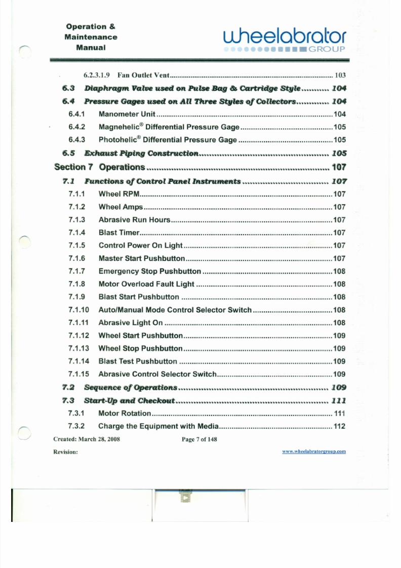
6.2.1 Shaker Bag Style 95
6.2.1.1 Elements of a Typical Shaker Bag Style Dust Collector: 96
6.2.1.1.1 Shaker Mechanism 96
6.2.1.1.2 Filter Bags 96
6.2.1.1.3 Cell Plate 96
6.2.1.1.4 Inlet Vent 97
6.2.1.1.5 Baffle PlatelLiner 97
6.2.1.1.6 Fan Outlet Vent 97
6.2.2 Pulse BagStyle 98
6.2.2.1 Elements of a Typical Pulse Bag Style Dust Collector: 99
6.2.2.1.1 Inlet Vent 99
6.2.2.1.2 Baffle PlatelLiner 99
6.2.2.1.3 Filter Bags 100
6.2.2.1.4 Compressed Air Reservoir 100
6.2.2.1.5 Air Manifold 100
6.2.2.1.6 Multi-Stage Nozzles 100
7/30/2019 MANUAL DE USUARIO GRANALLADORA (2).pdf
http://slidepdf.com/reader/full/manual-de-usuario-granalladora-2pdf 7/240
Operation &
Maintenance
ManualLlheelabrator
••••••••• GROUP
6.2.3.1.9 Fan Outlet Vent 103
6..3 Di hragrftVa usedOftPulseBag••Cartridge
Pressure Gages sedOftAll ftree Sf\vles ~ Collectors ......•......•..........Ot
6.4.1 Manometer Unit 104
6.4.2 Magnehelic® Differential Pressure Gage 105
6.4.3 Photohelic® Differential Pressure Gage 105
fS..S Bx:h tPiptng COftstruetioft •••••••••••••••••••••••••••••••••••••••••••05
ec on 7 Opera.tion "" ".." " ,." " " " 'II •• " ••••• ••••••• ••••••••• •• 1 07
7.1
7.1.1
7.1.2
7.1.3
7.1.4
7.1.5
7.1.6
7.1.7
Wheel RPM 107
Wheel Amps 107
Abrasive Run Hours 107
Blast Timer 107
Control Power On Light 107
Master Start Pushbutton 107
Emergency Stop Pushbutton 108

7/30/2019 MANUAL DE USUARIO GRANALLADORA (2).pdf
http://slidepdf.com/reader/full/manual-de-usuario-granalladora-2pdf 8/240
Operation &
Maintenance
ManualLlheelabrator
••• GROUP
7.3.3 BlastWheel 112
7.3.4 MediaHandling System 112
1 Y I ~ • . , I ~ l r l ~ " ~ . ~~~~. ~~~~~~~~~~~• • • • • . " " '• • • • • •' • • . " " ' . " ' ,• • •. . . . . . . .~
&1 1ft tio~ ReJKdrlReplacelMftt ofPalts & CofltlM)fteftts...•......•....13
8.1.1 BlastWheel Assembly 113
8.1.1.1 Liners 114
8.1.1.2 Wheel Housing 114
8.1.1.3 Wheel Blades, Control Cage & Impeller 114
8.1.1.4 Removal and Replacement ofBlast Wheel Impeller Bolt 115
8.1.2 CabinetAssembly 116
8.1.3 Work Conveyor Assembly 116
8.1.4 Work Conveyor DriveAssembly 116
8.1.5 Abrasive Recycling System 116
8.1.5.1 Abrasive Hopper 117
8.1.5.2 Elevator Belt Assembly 117
8.1.5.3 Elevator Drive 119
7/30/2019 MANUAL DE USUARIO GRANALLADORA (2).pdf
http://slidepdf.com/reader/full/manual-de-usuario-granalladora-2pdf 9/240
WO;J"onoJiuOlluq8IaaqM"MMM :UO!S!A;} l I
8t110 6 ;}~~d 800Z '8Z q;)UW :P;}J~;}.I;)
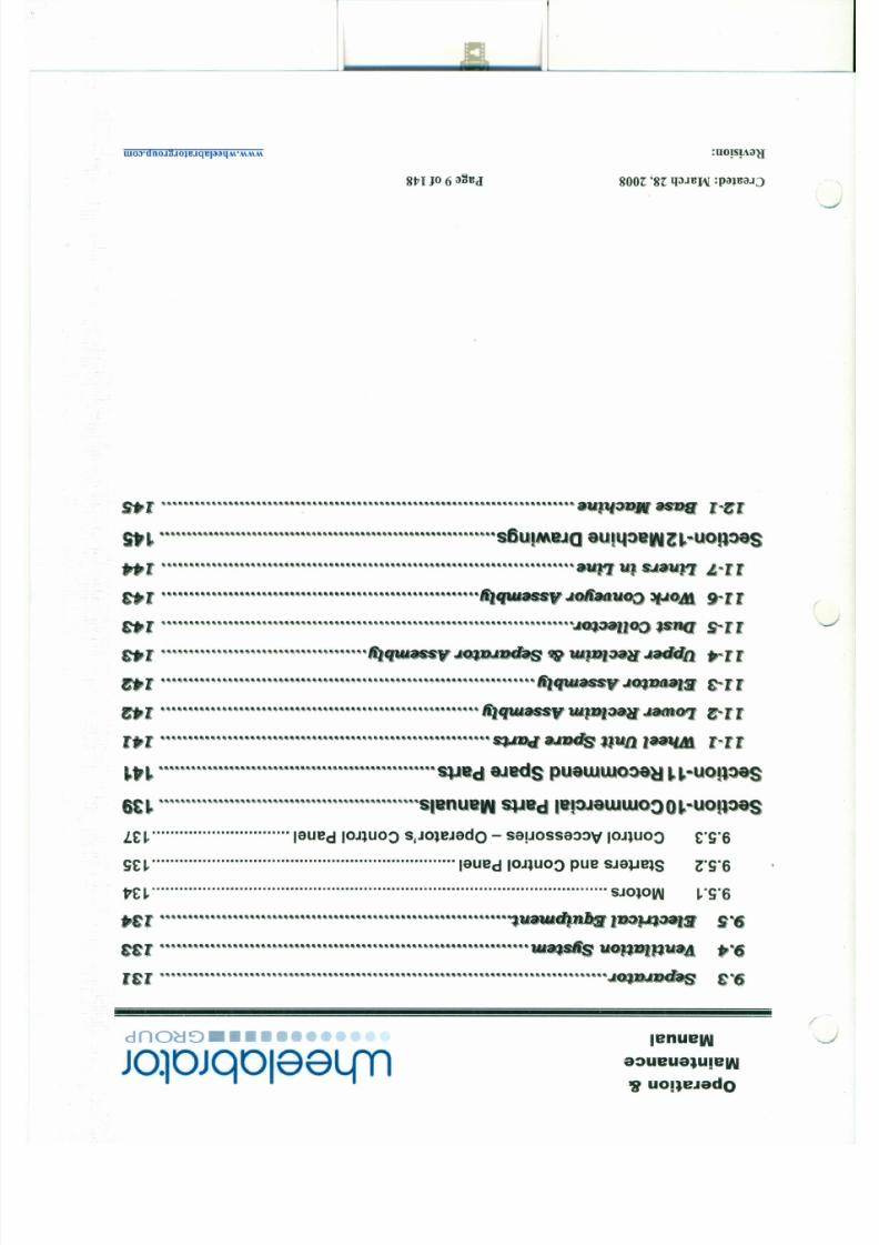
S.1•. . ., " , . .," ,', ,"",.,', . . . . • . . ., , ,', .
IlIJlp· l...~l
~ . . . . . . . . . . . . . . . . . . . . . . . . . . . . . . . . . . . . . . . . . . . . . . • . . . . . . • . • • . • • • ,U IM J a aUI'I:,) Z~"UOll:l&1
••••••••••••••••••••••••••••••••••••••••••••••••••••••••••••••••••••••••lIJ s..a.un - .1.'11»1•••• ., .. to liaavo :' ) ~Q.,"",., ,",., ,., , , . " . " . , . " . , " , . ,

7/30/2019 MANUAL DE USUARIO GRANALLADORA (2).pdf
http://slidepdf.com/reader/full/manual-de-usuario-granalladora-2pdf 10/240
Operation &
Maintenance
Manual
u .hee lab ra to r•••• GROUP
Section1 Introduction
1.1 Statement
This manualwill benefityou inseveral ways:
1. Itwill provide youwith safetywarnings
andinstructions to protectyouandyour
equipment frominjuries ordamage.
2. Itwill assist you inkeeping this equipment
inthebest possible mechanical condition
atall times.
3. Itwill helpyouobtainthemaximumperformancefromyour equipment.
Theinstructions andsuggestions contained
inthis manual arebaseduponpractical
operating experience. If followed theywill
help yougetthemost production and
satisfaction fromtheequipment.
Everyoneresponsible for theoperation and

7/30/2019 MANUAL DE USUARIO GRANALLADORA (2).pdf
http://slidepdf.com/reader/full/manual-de-usuario-granalladora-2pdf 11/240
Oper at ion &
Maintenance
Manual
u .hee l ab ra t o r••• o••• GROUP
1.2 Instruction andWarning Symbols
In this operation and maintenance manual the following symbols areused to identify important operation, maintenance and safety
instructions:
e.2.1 Readl
This sign I?dlcates advice regarding operation and maintenance.
&.2.2 Caution! I A CAUTION I Yellow background with black text
o This sign indicates rules and guidelines for a potentially hazardousg situation which, if not avoided, may result in minor or moderate
injury. It may also be used to alert against unsafe practices.
1.2.3 Warning! I A WARNING I•• Orange background with black text
This sign indicates rules and guidelines for a potentially hazardoussituation which, if not avoided, could result in death or seriousinjury.
1.2.4 Danger! A . DANGERRed background with black text
This sign indicates rules and guidelines for an imminently
J
J

7/30/2019 MANUAL DE USUARIO GRANALLADORA (2).pdf
http://slidepdf.com/reader/full/manual-de-usuario-granalladora-2pdf 12/240
Operat ion &
Maintenance
Manualuhee l a b r a t o r
•••• GROUP
o1.3.2 Understanding the Equipment
Before attempting to operate, service or maintain the equipment,
personnel should thoroughly familiarize themselves with thephysical make-up of the equipment, be familiar with the major
components of the equipment, and have a general understandingof overall operations.
1.3.3 Equipment Operators & Maintenance Personnel Qual if icat ions
1. Person must be of legal age for the location to operate and/orservice equipment.
2. Person must be able to read and understand the Englishlanguage to operate and/or service equipment.
3. Person must read and understand operation and maintenance
manual before operating and or servicing the equipment.
4. Person must be trained in the operation and safety of the
equipment before operating.
5. Only qualified maintenance personnel may service thisequipment.
7/30/2019 MANUAL DE USUARIO GRANALLADORA (2).pdf
http://slidepdf.com/reader/full/manual-de-usuario-granalladora-2pdf 13/240
Operation &
Maintenance
ManualL l hee lab r a t o r
r . . • . .. .• • • • GROUP
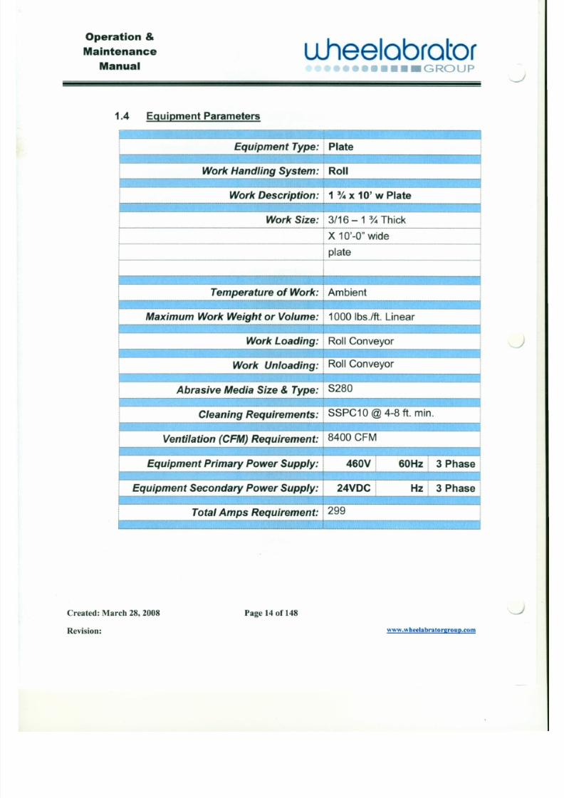
1.4 Equipment Parameters
Equipment Type: I Plate
Work Handling System: Roll._._._.__.__ . j
Y 4 x 10' w Plateork Descr., . . _ ~ ~ . . ~ . •. ~ M .. . . . . . . . . . . . . . .. . M . . ' . •• •". ~ . . . . . . .. . . . .• _ , _ _ . • • . , _ .
Work Size: 3/16 - 1% Thick. ~ ;---_.. ._--------_._--_._-
! X 10'-0" widei
I plate
~~-·-··T··---·~----Temoereture o f W~r k; A;;-bient--'-'-
f-------.-----.-
................................. ................................................ ............................... .......................,...
Maximum Work Weight or Volume: 1000 Ibs./ft. Linear
~ ~
, Work Loading: I Roll Conveyor '. .- - - - , - - : . . . . - - " .. . - . .- - . ~ - ~ ' . , .. . . - - . .- .. - - - - - ~ - ~ .. - + - . . . . . ; .- pope 4
••••••••••••••••••••••••••••• _" ••••••••••••••••••• - ••••••••••••••••• _ •••••_ ••_ ••••••_HH •••••••• ••••, ••••••••••t : _- · · HH•••
; Work Unloading: Roll Conveyor i
I 'M" I-1-- _ .- -.-.----. .!-..._---_ ....-- --_ .
J
7/30/2019 MANUAL DE USUARIO GRANALLADORA (2).pdf
http://slidepdf.com/reader/full/manual-de-usuario-granalladora-2pdf 14/240
Operation &
Maintenance
Manual
u.heelabrator•••• GROUP
" - . . . - /
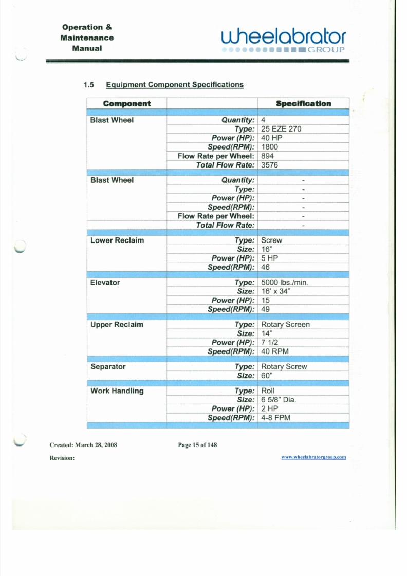
1.5 Equipment Component Specifications
,---__-----
Component Specification
Blast Wheel ---~--··T-·--······-~m Quantity: T 4 ITy.e.e: ! 25 EZE 270
Speed(RP~):1 1800Power (HP): I 40 HP 1
jlow Rate~er Wheel: ! 894Total Flow Rate: I 3576
i Blast Wheel · · - - - · - · · · - T - · - ·= = -= ~ · - - Q i i a n t i ~ : T - - - - - - I
~.-- .- - - .-.-T . y . e .~;J..-..---.- .-~- - ----.-JI Power (HP1 : i - !-_ •••••• _ •••••••••••••••••••••••••••••••••••••••••••••••••••••• m••• m••••••••••••••••••••••••••••••••••••••••••••••••••••••• .[ ••••••••••••••••••••••••• _ •••••••••••••••••• _ •••••••••••••••••••••• _ ••••••••••• _ •
i L . . . . . . . . . . _ . . . . § . ~ ~ ~ q ( f .! :~ M l ; J . . m . . . . _ . . . . . . . . m _ . . . .I I Flow Rate per Wheel: Ir - m .. . . .. . . . . . .. . . . . . . . .. . . . .. . m . . . . . . . .m . I . . m . . . . .T o t a l . i = i o w " / : j i J t e . : I . .m . . . . . . . . . . .. . . . . . . . . . . . . . . m
r - I ~ o w e r R e c f a i m = " ' " · · · · · ' · r · · · · · = · ~ ~ : : '· :. = . · . : " : " : ~ . · · ~ · - · . : : : ~ ~ f i ~ ~ i t ~ ~ ~ ~ ~ · - ·. - ·. •· : ~ · - · · ·- · ~ - " " · -- """~~·~=:. ii i Size: I 16" I
!------_ _ .._.. .~----.-. ---~
L--.-. Power (HP): I5 HP II Speed(RP~):146
~ __ .__.. ! d" ,

7/30/2019 MANUAL DE USUARIO GRANALLADORA (2).pdf
http://slidepdf.com/reader/full/manual-de-usuario-granalladora-2pdf 15/240
•
Operat ion &
Maintenance
Manual
u .hee lab ra to r•••• GROUP
Section 2 Warranty
WARRANTY 3463
Gunderson-Gimsa
P.urdlas.e Order Number GG05747·1
Seller warrants that the equipment described herein will be free from defects in materialand workmanship for a period of twelve (12) months from delivery ("Warranty Period").
If within the Warranty Period Seller receives written notice promptly after the discovery
of any defect in the material or workmanship Seller shall correct each such defect FOBpoint of manufacture. Seller shall undertake its warranty obligation of repair,replacement within a reasonable time of receiving actual notice of the warranty defect.
Seller shall be fully compensated for expenses of travel and for job time (at Seller's thenprevailing per diem rates for straight time and premium time, as applicable) of its service
representatives who inspect warranty claims that are not warranty issues. Buyer shallissue a purchase order for these expenses prior to Seller's representatives arrival onsite Purchaser has no right to and may not backcharge Seller for warranty claimswithout prior approval. Normal wear parts and labor are not included. The liability of
-.,. Seller to Purchaser/Buyer arising out of or the supplying of the equipment whether
under warranty, tort, contract, negligence, strict liability or otherwise, shall not in anycase exceed the cost of correcting defects in Equipment and upon the expiration of said
warranty, all such liability shall terminate. This warranty is conditioned upon theEquipment being handled, operated, and maintained in accordance with written
7/30/2019 MANUAL DE USUARIO GRANALLADORA (2).pdf
http://slidepdf.com/reader/full/manual-de-usuario-granalladora-2pdf 16/240
Operation &
Maintenance
Manualuheelabrator
•••• GROUP
Section 3 Safety - Warnings & Precautions
3.1 LockoutlTagout
One of the most widely applicable industrial safety principles is
Lockoutrragout. The Occupational Safety and Health Administration
(OSHA) and the American National Standards Institute (ANZI) haveboth addressed the requirement for LockouUTagout. OSHA requires
that each employer formulates a written procedure for implementing aLockouUTagout safety program, including training employees to assure
that it is properly utilized. The following are a few important points to
keep in mind.
1. The principle of LockouUTagout is to protect personnel from the
unexpected energization, start up, or release of stored energy from
the equipment or process.
2. The LockouUTagout principle requires that locks and tags be
affixed to the point where energy can be disconnected from the
equipment or process.
3. Sources of energy are not restricted to electrical; that is,
disconnecting the main power switch may not eliminate all sourcesof unexpected activation. While electrical power always should be
disconnected, a person knowledgeable about the equipment or
7/30/2019 MANUAL DE USUARIO GRANALLADORA (2).pdf
http://slidepdf.com/reader/full/manual-de-usuario-granalladora-2pdf 17/240
Operation &
Maintenance
Manualuheelabrator
•••• GROUP
e
3.2 MediaWarnings
3.2.1 Highly Explosive Dust
Products (parts), which produce highly explosive
dust, such as Magnesium Titanium Zirconium Thorium etc.,should not be processed in this equipment, unless appropriatesafety measures are followed (consult expert authority). Obtain
approval of your plant safety director and comply with applicableNFPA (National Fire Protection Association) guidelines.
Note: Personnel should not smoke. usematches nor have
open flames around this equipment during operation.
3.2.2 Alumnum Media & Parts
Comply with all applicable sections of NFPA guidelines for
processing or handling of aluminum dust and fines that may bepertinent to your specific operation.
In applications involving the use of dry type bag or cartridge dustcollector system and Aluminum Media or surface blasting of
Aluminum Parts, precautionary measures must be taken tominimize the risk of dust collector fires and/or explosions. The
following procedures should be followed.
~
J

7/30/2019 MANUAL DE USUARIO GRANALLADORA (2).pdf
http://slidepdf.com/reader/full/manual-de-usuario-granalladora-2pdf 18/240
Operation &
Maintenance
Manualu.heelabrator
.oo•••••• GROUP' - - - - - '
3.2.2.3 DuctworkVelocity- AlumnumApplications
Maintain ductwork air velocity of not less than 4500 FPM.
3.3 MaintenanceWarning- Electrical
WARNING

7/30/2019 MANUAL DE USUARIO GRANALLADORA (2).pdf
http://slidepdf.com/reader/full/manual-de-usuario-granalladora-2pdf 19/240
Operati on &
Maintenance
Manual
L l hee l ab r a t o r•••• ,...,.,••• G RO U P
3.4 Electrical Precautions
Throughout this manual are safety warnings and precautions that mustbe obeyed by maintenance and operating personnel. Although the
precautions which follow may seem to be over simplified, they shouldbe included in the "Buyer's Safety Program." These are minimumsafety requirements for this equipment and any additional plant safety
requirements for your facility shall also be obeyed.
3.4.1 Control Panel
1. DO NOT operate the equipment with the
control panel door open.
2. DO NOT use oversized fuses or bypass
any fuses. Refer to Electrical Drawing.
3. DO verify the correct thermal overload(s)
are installed for the motor starter(s) for the
full load amp rating of the motor(s) as shownon the motor nameplate.
4. DO verify the set point knob on motor J
starter overload relay(s) are set to match
amperage called out for on electrical drawing

7/30/2019 MANUAL DE USUARIO GRANALLADORA (2).pdf
http://slidepdf.com/reader/full/manual-de-usuario-granalladora-2pdf 20/240
Operat ion &
Maintenance
Manual
uheelabrator.lvv"•••• _GROUP
' - - -
5. DO verify the motor's nameplate before starting the motor(s), to
ensure that the correct power supply (voltage, frequency, and
phase) is being used and that the motor(s) is/are connected
according to the connection diagram on the nameplate. Verifythat the motor is connected properly for the correct rotation. If
motor(s) rotate in the wrong direction, a qualified electrical
person may interchange any two line leads at the starter in thecontrol panel. (Ref.2-3.2)
6. DO NOT use the eyebolt on the motor(s) to lift the motor with
any additional equipment attached to the motor(s).
3.4.3 Equipment Instal lat ion Wiring
DO verify the equipment is wired and connected with wire of the
correct size and correct insulation.
3.4.4 Equipment Safety Grounding
1. DO verify the equipment, as installed, is effectively grounded.
2. DO verify the equipment is grounded in accordance with NEe
and any other applicable state or local codes.
7/30/2019 MANUAL DE USUARIO GRANALLADORA (2).pdf
http://slidepdf.com/reader/full/manual-de-usuario-granalladora-2pdf 21/240
Operation &
Maintenance
Manualuheelabrator
••••••••• GROUP <
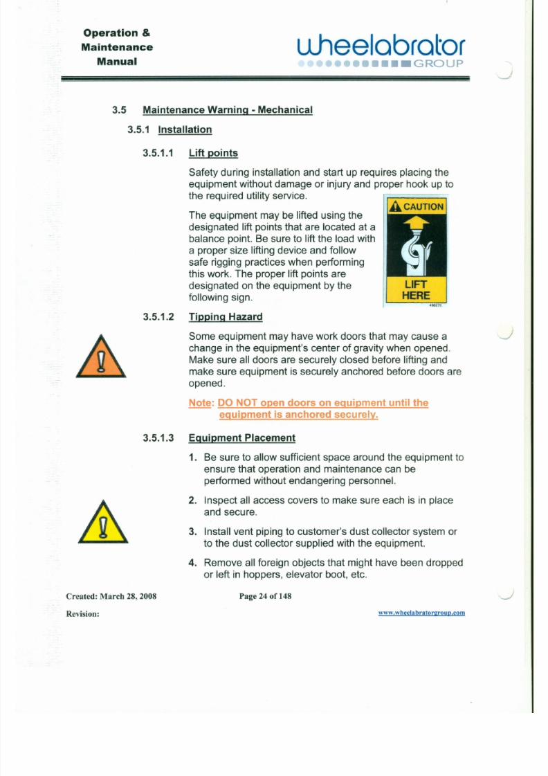
3.5 Maintenance Warning -Mechanical
3.5.1 Installation
3.5.1.1 Lift points
Safety during installation and start up requires placing the
equipment without damage or injury and proper hook up tothe required utility service.
The equipment may be lifted using the
designated lift points that are located at abalance point. Be sure to lift the load with
a proper size lifting device and followsafe rigging practices when performing
this work. The proper lift points aredesignated on the equipment by thefollowing sign.
LIFTHERE04 98216
3.5.1.2 Tipping Hazard
Some equipment may have work doors that may cause a Jchange in the equipment's center of gravity when opened.Make sure all doors are securely closed before lifting and
make sure equipment is securely anchored before doors are
7/30/2019 MANUAL DE USUARIO GRANALLADORA (2).pdf
http://slidepdf.com/reader/full/manual-de-usuario-granalladora-2pdf 22/240
Operation &
Maintenflnce
Manual
L1heelabrator•••• GROUP
"'--"'
3.5.2 Items to be checked and completed before start-up
1. Install breathers on speed reducers.*a.) Remove solid fill plug(s) located at the highest position and
on the slow (output) side of each reducer. Ensure oillevel(s)
is/are correct with recommended lubricant(s). (See
lubrication chart in Section 5)
b.) Replace solid fill plug with breather plug(s) which is/are
enclosed in packet inside electrical panel.
*Note: Some units may be equipped with combination plugsthat do not require replacement. Check for air/pressure
vent hole in plug before removing. Only un-vented
plugs need to be changed.
2. Check motor rotation on all drives.
3. This equipment is normally wired to operate from 460V AC, 3
Phase, and 60 HZ electrical supply. Factory supplied options
for 575V AC, 3 Phase, 60 HZ or 230V AC, 3 Phase, 60 HZ
operation are available.
4. Before starting the equipment, check that the equipment is

7/30/2019 MANUAL DE USUARIO GRANALLADORA (2).pdf
http://slidepdf.com/reader/full/manual-de-usuario-granalladora-2pdf 23/240
Operation &
Maintenance
Manual.u.heelabrator
•••• GROUP
3.6.1 Mechanical Do's &Don'ts Items:
1. DO Achieve Zero Mechanical State (ZMS) before performingmaintenance on the equipment.
a.) DO lockout every power source that can produce mechanicalmovement.
b.) DO lockout shut off valves for pressurized fluid (air, oil or other).
c.) DO reduce all accumulators and air surge tanks to atmospheric
pressure.
d.) DO achieve the lowest practical value for mechanical potential
energy for all portions of the equipment.
Example: A belt and bucket elevator system that has stoppedwith the buckets containing abrasive may reversefrom the weight of the abrasive in the buckets.
e.) DO achieve the lowest practical value for kinetic energy of the
equipment members. Loose or freely movable equipment
members and parts must be secured against accidental
.J
J
7/30/2019 MANUAL DE USUARIO GRANALLADORA (2).pdf
http://slidepdf.com/reader/full/manual-de-usuario-granalladora-2pdf 24/240
Operation &
Maintenance
Manualuheelabrator
••••• GROUP
'- . . - - -
5. DO NOT wear loose fitting clothes, jewelry and watches, while
working near belts, chains, sprockets, shafts or other components
that are movable.
6. DO keep the areas around all equipment clean. Loose abrasive
media and dust can cause hazardous conditions.
7. DO immediately correct any condition(s) that may result indamage to the equipment or cause injury to personnel.
8. DO NOT use your hands to remove excess abrasive from the
elevator boot section, rotary screen, screw conveyor or shakerconveyor. Always use a scoop or scraper for removing this
abrasive.
9. DO NOT attempt to adjust the feed spout, or other wheel parts
while the blast wheel is operating or rotating.
10. DO NOT attempt to adjust the component parts of the abrasive
recycling system or the work parts conveyor system while any partof the blast equipment is in operation.
7/30/2019 MANUAL DE USUARIO GRANALLADORA (2).pdf
http://slidepdf.com/reader/full/manual-de-usuario-granalladora-2pdf 25/240
Operation &
Maintenance!
ManuaJ
u .hee lab ra to r••• GROUP
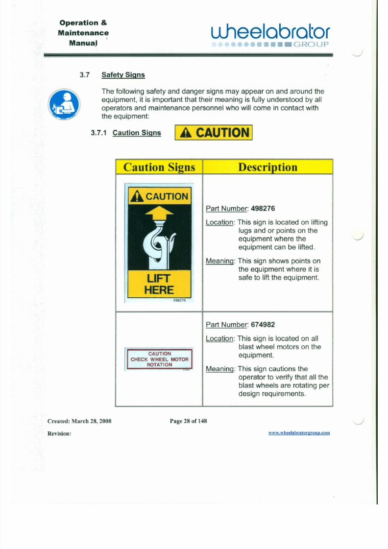
o3.7 Safety Signs
The following safety and danger signs may appear on and around theequipment, it is important that their meaning is fully understood by all
operators and maintenance personnel who will come in contact withthe equipment:
3.7.1 Caution Signs I A CAUTION ICaution Sians I Descrintlon
Part Number: 498276
Location: This sign is located on liftinglugs and or points on the
equipment where the
equipment can be lifted.
J

7/30/2019 MANUAL DE USUARIO GRANALLADORA (2).pdf
http://slidepdf.com/reader/full/manual-de-usuario-granalladora-2pdf 26/240
Operation &
Maintenance
Manual
l .JJ lee labra to r••• GROUP
<:»
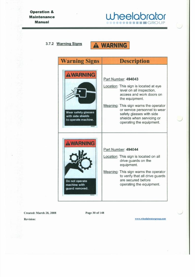
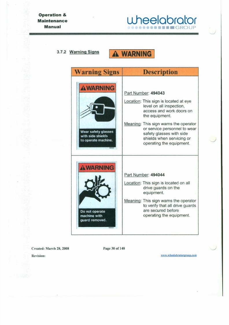
3.7.2 Warning Signs A WARN I NG
A W A R N I N G
Descrlntion
Part Number: 494043
Location: This sign is located at eye
level on all inspection,access and work doors on
the equipment.
Meaning: This sign warns the operator
or service personnel to wearsafety glasses with side
shields when servicing or I J
operating the equipment.
7/30/2019 MANUAL DE USUARIO GRANALLADORA (2).pdf
http://slidepdf.com/reader/full/manual-de-usuario-granalladora-2pdf 27/240
Operation &
Maintenance
Manual\...--
uheelabrator•••••• GROUP
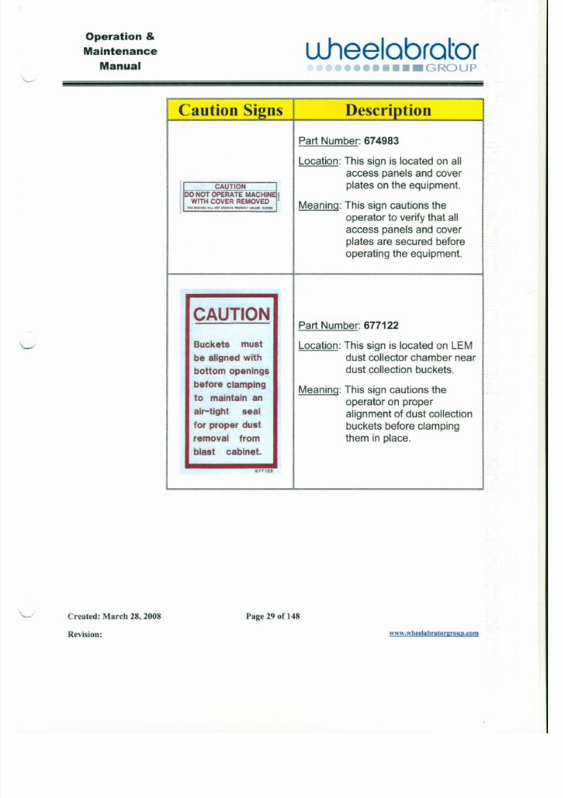
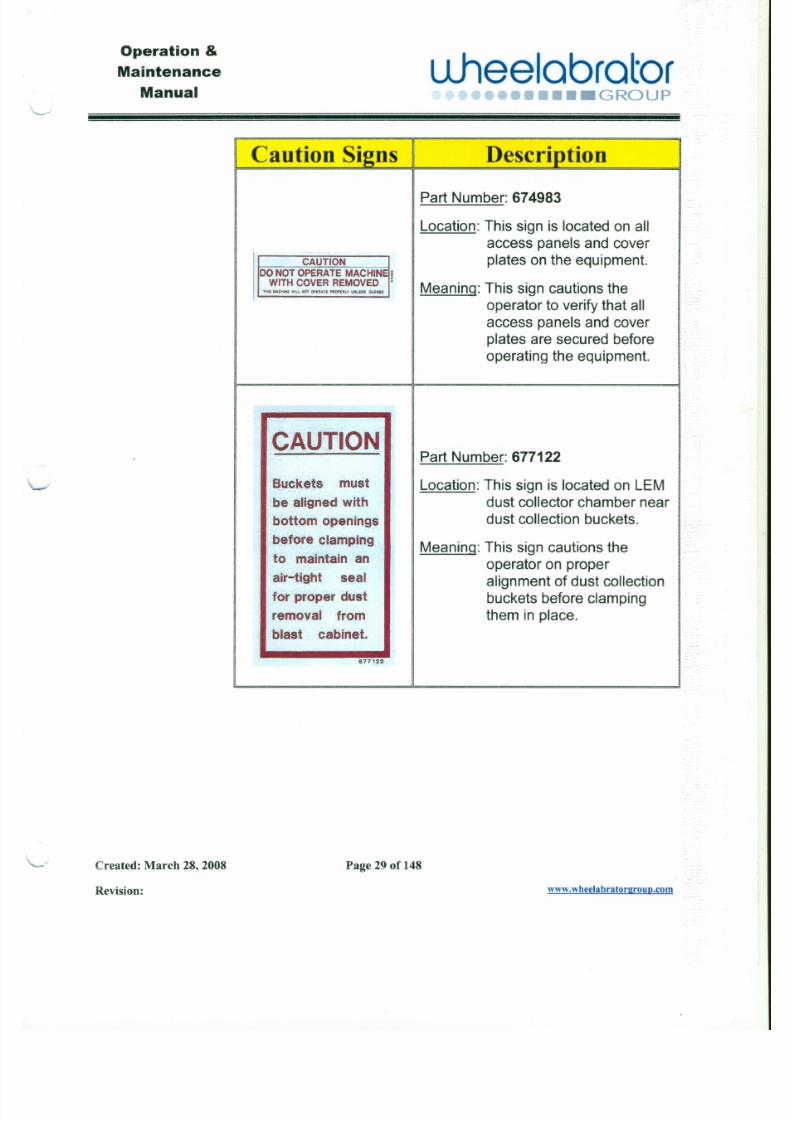
I Caution Signs I Description
Part Number: 674983
Location: This sign is located on all
access panels and cover
CAUTION plates on the equipment.DO NOT OPERATE MACHINE iWITH COVER REMOVED :
Meaning: This sign cautions theH II MACHINE Will HOTOP!II.t.TE PAOPElt Ly UNLU_ CLOUO
operator to verify that all
access panels and coverplates are secured beforeoperating the equipment.
CAUTIONPart Number: 677122
Buckets must Location: This sign is located on LEMbe aligned with dust collector chamber near
bottom openings dust collection buckets.
7/30/2019 MANUAL DE USUARIO GRANALLADORA (2).pdf
http://slidepdf.com/reader/full/manual-de-usuario-granalladora-2pdf 28/240
Operation &
Maintenance
ManualL l hee l ab ra t o r
•••• GROUP
J
3.7.2 Warning Signs I A WARN ING I
Warn in
A W A R N IN G
Location: This sign is located at eyelevel on all inspection,access and work doors on
the equipment.
Meaning: This sign warns the operator
or service personnel to wear
safety glasses with side
shields when servicing or! J
operating the equipment.
Descrlntlon
Part Number: 494043
7/30/2019 MANUAL DE USUARIO GRANALLADORA (2).pdf
http://slidepdf.com/reader/full/manual-de-usuario-granalladora-2pdf 29/240
Operation &
Maintenance
Manual\ . . . . . . . - - -
u.heelabrator••••• GROUP
I I Caution Signs I Description
Part Number: 674983
Location: This sign is located on all
access panels and cover
CAUTION plates on the equipment.DO NOT OPERATE MACHINE iWITH COVER REMOVED •
Meaning: This sign cautions theHl t MACHINE WIU HOTOP!IIAU " ,O PE IILV UHLI" CLOIID
operator to verify that all
access panels and coverplates are secured beforeoperating the equipment.
CAUTIONPart Number: 677122
Buckets must Location: This sign is located on LEMbe aligned with dust collector chamber near
bottom openings dust collection buckets.
7/30/2019 MANUAL DE USUARIO GRANALLADORA (2).pdf
http://slidepdf.com/reader/full/manual-de-usuario-granalladora-2pdf 30/240
Operation &
Maintenance
Manual
L l hee l ob ro t o r••• GROUP
J
3.7.2 War ni ng Si gn s A WARN I NG
Warn in
A W A R N I N G
Location: This sign is located at eyelevel on all inspection,
access and work doors on
the equipment.
Meaning: This sign warns the operatoror service personnel to wear
safety glasses with side
shields when servicing or I Joperating the equipment.
Descriotion
Part Number: 494043
7/30/2019 MANUAL DE USUARIO GRANALLADORA (2).pdf
http://slidepdf.com/reader/full/manual-de-usuario-granalladora-2pdf 31/240
Operation &
Maintenance
ManualL l hee l ab ra t o r•••••••••• GROUP
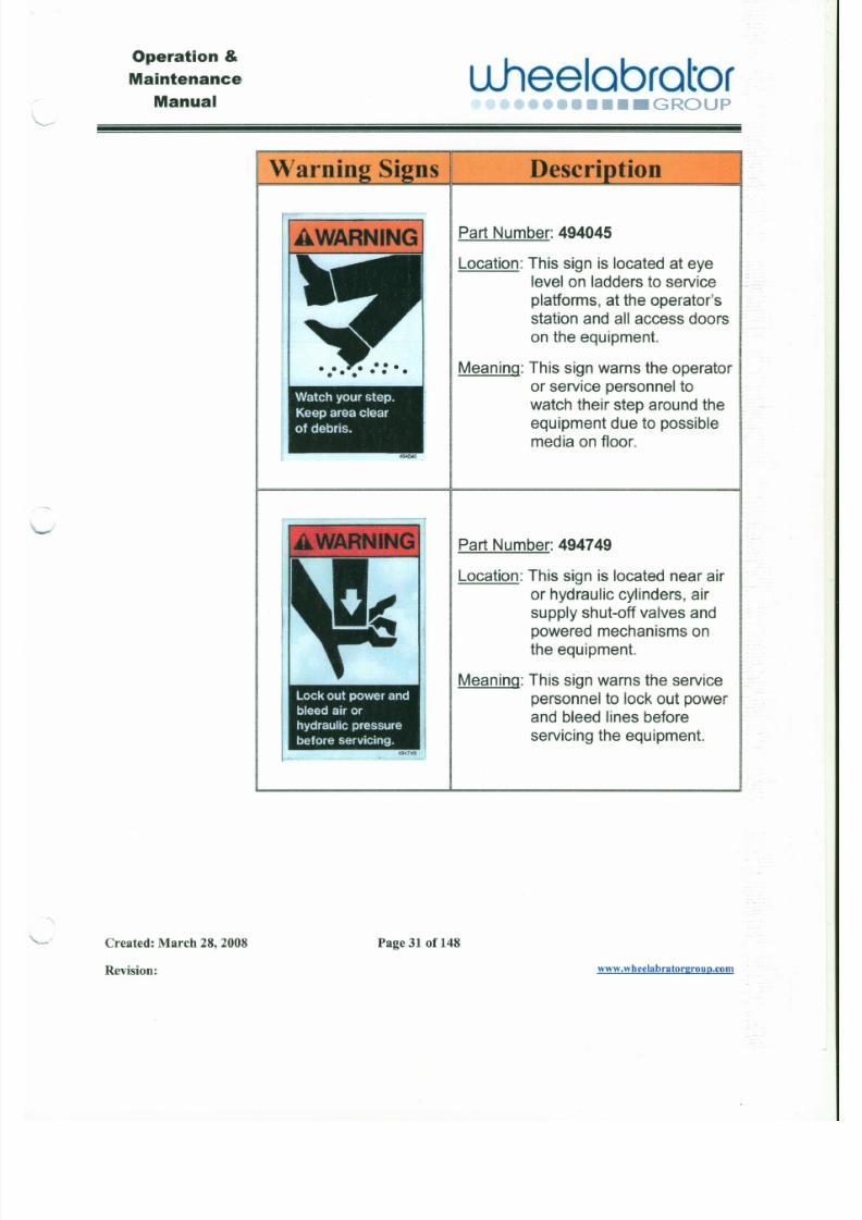
Warnin
Watchyour step.
Keepareaclear
of debris.
494045
ns Descriotion
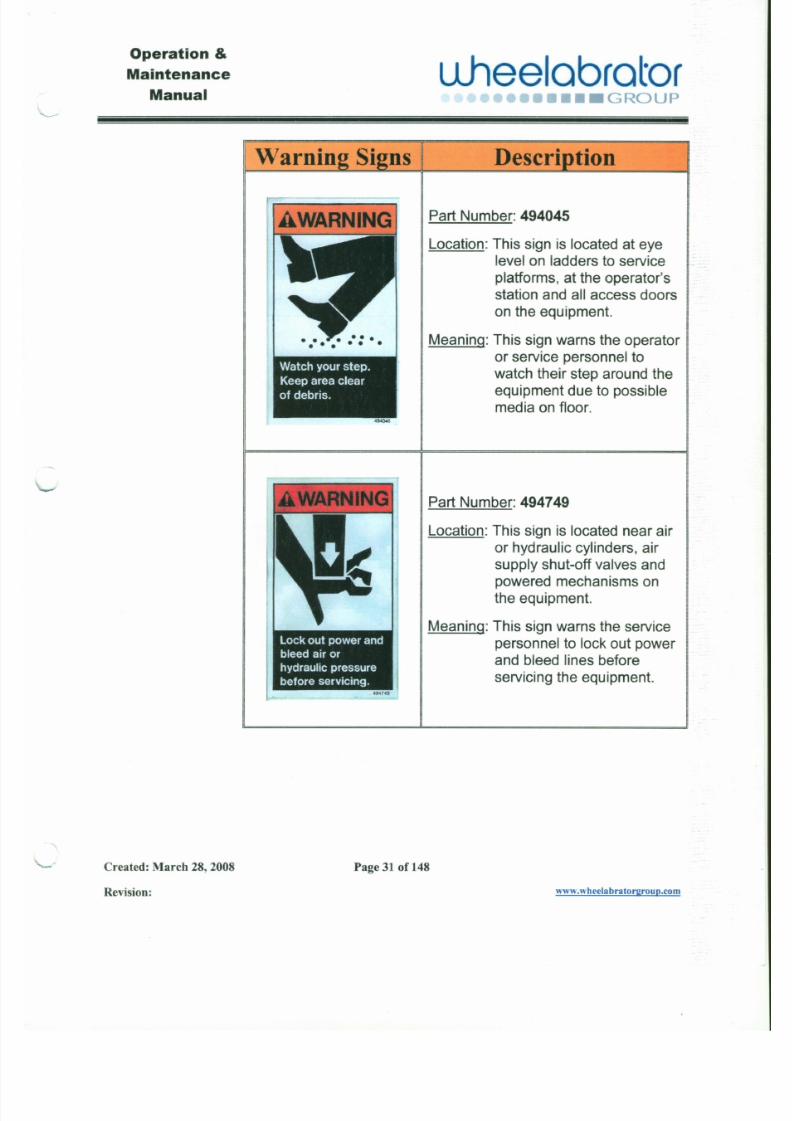
Part Number: 494045
Location: This sign is located at eyelevel on ladders to service
platforms, at the operator'sstation and all access doorson the equipment.
Meaning: This sign warns the operatoror service personnel to
watch their step around the
equipment due to possible
media on floor.
Part Number: 494749
7/30/2019 MANUAL DE USUARIO GRANALLADORA (2).pdf
http://slidepdf.com/reader/full/manual-de-usuario-granalladora-2pdf 32/240
Operation &
Maintenance
ManualL1hee lab ra to r
••• GROUP
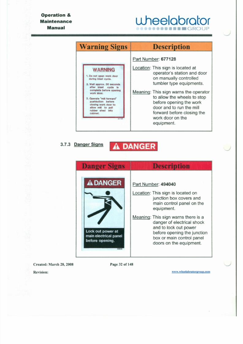
Warning Signs Description
Part Number: 677128
WARNINGI Location: This sign is located at
1. Donot open work dooroperator's station and door
during blast cycle. on manually controlled
2. Waitapprox. 30 seconds tumbler type equipments.after blast cycle Is
complete before openingMeaning: This sign warns the operatorork door.
3. Operate "mill forward" to allow the wheels to stoppushbutton before before opening the workclosing work door to
allow mill to pull door and to run the millrubber shed Into
forward before closing theabinet.
.1112.' work door on the
equipment.
3.7.3 Danger Signs A DANGER
-"
-...-/
J
7/30/2019 MANUAL DE USUARIO GRANALLADORA (2).pdf
http://slidepdf.com/reader/full/manual-de-usuario-granalladora-2pdf 33/240
Operation &
Maintenance
Manualuheelabrator
.O•••• GROUP
I I
Warning Signs I Description I
Part Number: 677128
WARNING Location: This sign is located at
1. Donot open work dooroperator's station and door
during blast cycle. on manually controlled
2. Waitapprox. 30 seconds tumbler type equipments.after blast cycle Is
complete before openingMeaning: This sign warns the operatorork door.
3. Operate "mill forward" to allow the wheels to stoppushbutton before before opening the workclosing work door to
allow mill to pull door and to run the millrubber shed into
forward before closing theabinet.
In 12.1 work door on the
equipment.
3.7.3 Danger Signs ,A DANGER
-.../
J
7/30/2019 MANUAL DE USUARIO GRANALLADORA (2).pdf
http://slidepdf.com/reader/full/manual-de-usuario-granalladora-2pdf 34/240
Operation &
Maintenance
Manual
uheelobrotor•• o>••...•...,•• GROUP
Warnin
Watchyourstep.
Keepareaclear
of debris.
'94046
Descriotion
Part Number: 494045
Location: This sign is located at eye
level on ladders to service
platforms, at the operator'sstation and all access doorson the equipment.
Meaning: This sign warns the operator
or service personnel to
watch their step around the
equipment due to possible
media on floor.
Part Number: 494749
7/30/2019 MANUAL DE USUARIO GRANALLADORA (2).pdf
http://slidepdf.com/reader/full/manual-de-usuario-granalladora-2pdf 35/240
Operation &
Maintenance
Manual
' - - - -
u .h e e l a b r a t o r••••••••• GROUP
Lethal Voltage.
Authorized
access only.
494041
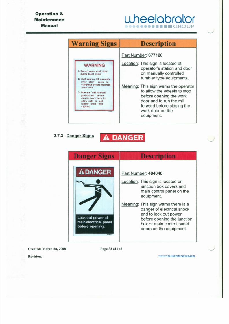
Part Number: 494041
Location: This sign is located on
junction box covers and
main control panel on theequipment.
Meaning: This sign warns there is a
danger of electrical shock
and only authorized
personnel shall gain access
to the junction boxes and
main control panel on theequipment.
7/30/2019 MANUAL DE USUARIO GRANALLADORA (2).pdf
http://slidepdf.com/reader/full/manual-de-usuario-granalladora-2pdf 36/240
Operation &
Maintenance
Manualu J l e e l a b r a t o r
•••• GROUP
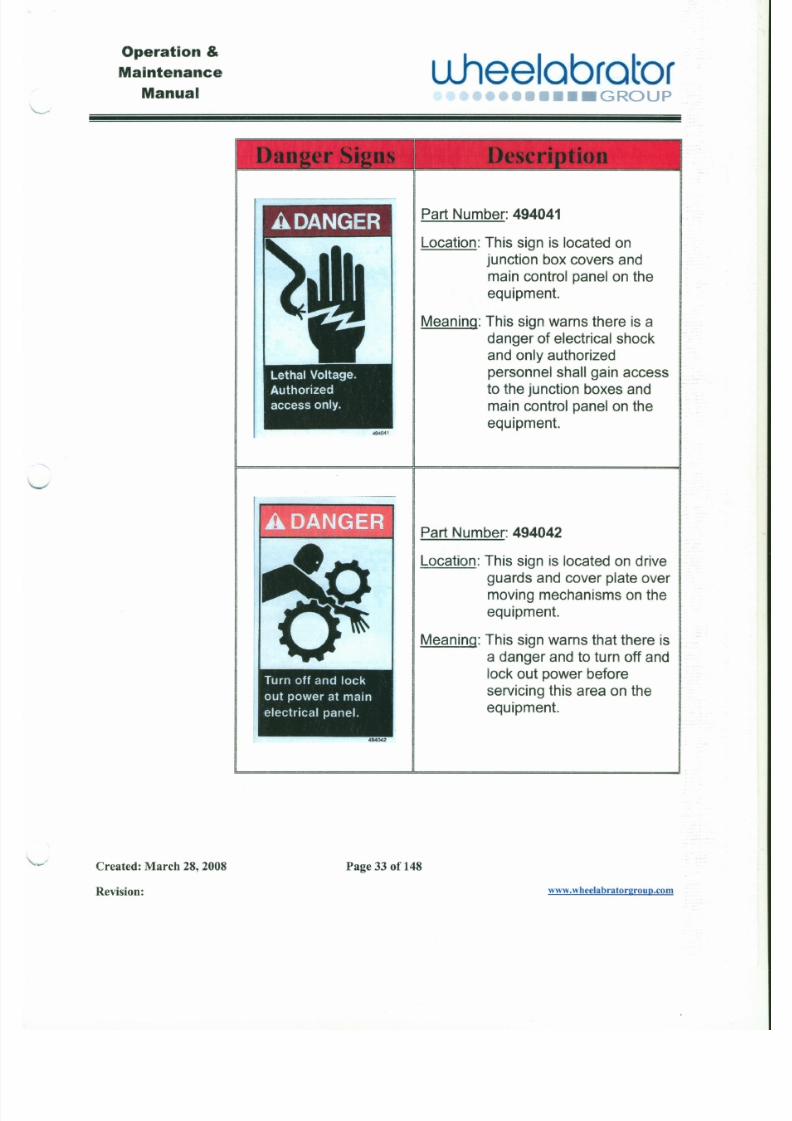
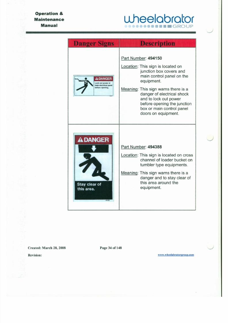
Part Number: 494150
Location: This sign is located on
junction box covers and
main control panel on theequipment.
Meaning: This sign warns there is a
danger of electrical shock
and to lock out power
before opening the junction
box or main control paneldoors on equipment.
Part Number: 494388
J
7/30/2019 MANUAL DE USUARIO GRANALLADORA (2).pdf
http://slidepdf.com/reader/full/manual-de-usuario-granalladora-2pdf 37/240
Operation &
Maintenance
Manual
" - - - -
u .h e e l a b r a t o r•••• GROUP
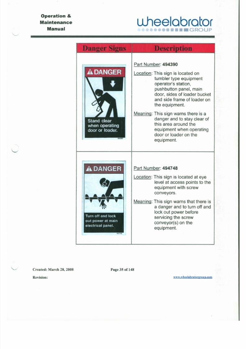
Part Number: 494390
Location: This sign is located on
tumbler type equipment
operator's station,pushbutton panel, main
door, sides of loader bucket
and side frame of loader onthe equipment.
Meaning: This sign warns there is a
danger and to stay clear of
this area around theequipment when operating
door or loader on theequipment.
7/30/2019 MANUAL DE USUARIO GRANALLADORA (2).pdf
http://slidepdf.com/reader/full/manual-de-usuario-granalladora-2pdf 38/240
Operation&
Maintenance
ManualuJ leelabrator
•••• GROUP
Stay clearof
pinchpoints.
".4750
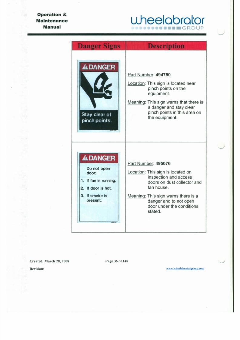
Part Number: 494750
Location: This sign is located nearpinch points on theequipment.
Meaning: This sign warns that there is
a danger and stay clear
pinch points in this area onthe equipment.
A DANGER
J
7/30/2019 MANUAL DE USUARIO GRANALLADORA (2).pdf
http://slidepdf.com/reader/full/manual-de-usuario-granalladora-2pdf 39/240
Operation &
Maintenance
ManualL L h e e l a b r a t o r
r . .r ." " , ... ., ... ., ... ,, . •• _GROUP
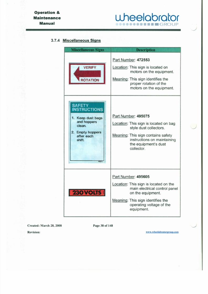
3.7.4 Miscellaneous Signs
Part Number: 472553
Location: This sign is located on
motors on the equipment.
Meaning: This sign identifies the
proper rotation of the
motors on the equipment.
SAFETYINSTRUCTIONS
1. Keep dust bags I I
and hoppers
clean.
2. Empty hoppers
after each
Part Number: 495075
Location: This sign is located on bag
style dust collectors.
Meaning: This sign contains safety
J
J
7/30/2019 MANUAL DE USUARIO GRANALLADORA (2).pdf
http://slidepdf.com/reader/full/manual-de-usuario-granalladora-2pdf 40/240
Operation &
Maintenance
Manualuheelobrotor
••••••••• GROUP
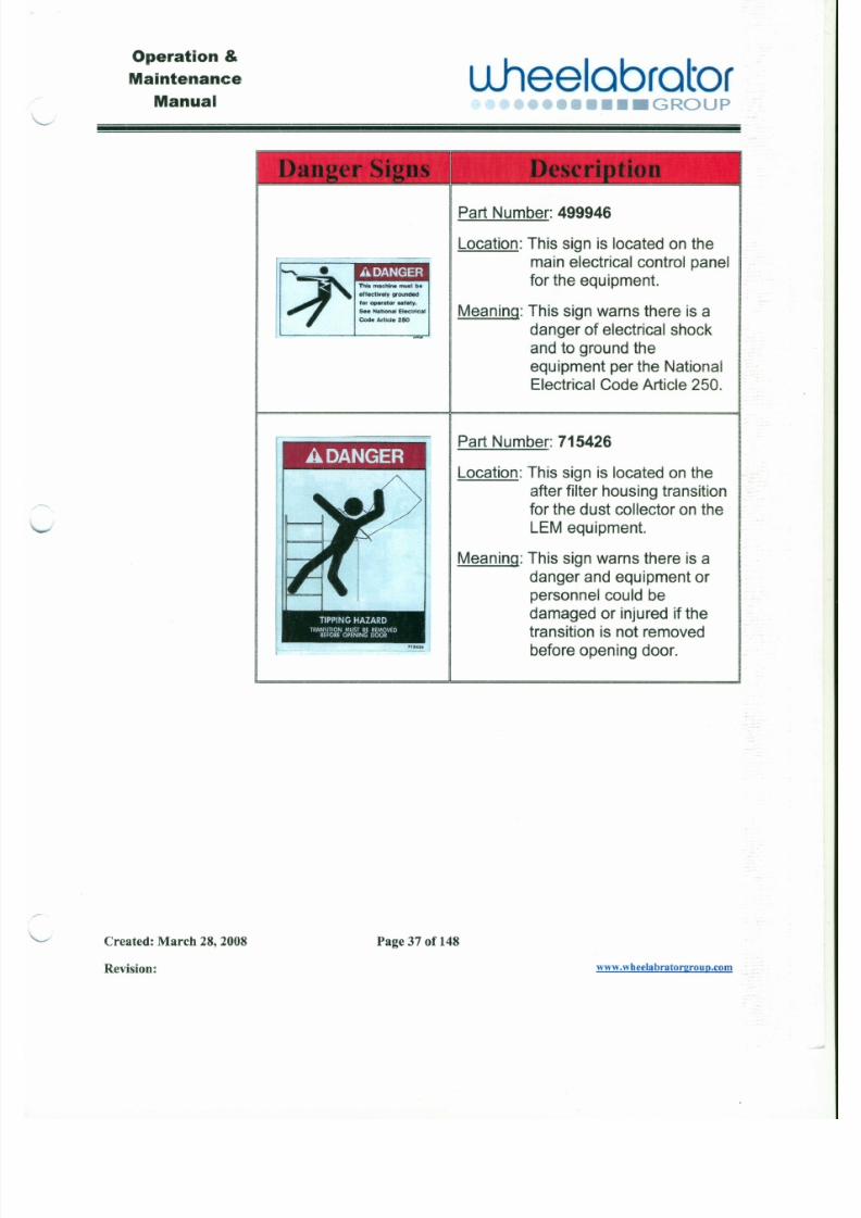
Part Number: 499946
Location: This sign is located on the
main electrical control panelfor the equipment.
Meaning: This sign warns there is a
danger of electrical shock
and to ground the
equipment per the National
Electrical Code Article 250.
I" , " " , • •
::f' Thl. machine •••••t ••
•tfectly~y grounded
forop«ator H'.ty.
s.. Nattonal Elect,leal
COOe Artic le 250
Part Number: 715426A DANGER
Location: This sign is located on the
after filter housing transition
for the dust collector on theLEM equipment.
Meaning: This sign warns there is a
danger and equipment or

7/30/2019 MANUAL DE USUARIO GRANALLADORA (2).pdf
http://slidepdf.com/reader/full/manual-de-usuario-granalladora-2pdf 41/240
Operation &
Maintenance
Manualuheelabrator
•••• GROUP
3.7.4 Miscellaneous Signs
Part Number: 472553
Location: This sign is located on
motors on the equipment.
Meaning: This sign identifies the
proper rotation of themotors on the equipment.
SAFETYINSTRUCTIONS
1. Keep dust bags I I
and hoppers
clean.
2. Empty hoppers
after eachshift.
Part Number: 495075
Location: This sign is located on bag
style dust collectors.
Meaning: This sign contains safety
J
J

7/30/2019 MANUAL DE USUARIO GRANALLADORA (2).pdf
http://slidepdf.com/reader/full/manual-de-usuario-granalladora-2pdf 42/240
Operation &
Maintenance
Manual
L l h e e l a b r a t o r•••• GROUP
I " "" • •
: : r -
Th ,. ••• chino •••••••••
eff ec ti ve ly grounded
for operator Ntely.
Se. Na tt onal Electrical
Code Article 250
A DANGERLocation: This sign is located on the
after filter housing transition
for the dust collector on theLEM equipment.
Meaning: This sign warns there is a
danger and equipment or
Part Number: 499946
Location: This sign is located on the
main electrical control panelfor the equipment.
Meaning: This sign warns there is a
danger of electrical shock
and to ground the
equipment per the National
Electrical Code Article 250.
Part Number: 715426
7/30/2019 MANUAL DE USUARIO GRANALLADORA (2).pdf
http://slidepdf.com/reader/full/manual-de-usuario-granalladora-2pdf 43/240
Operation &
Maintenance
Manual
"--
L i h e e l a b r a t o r••••• GROUP
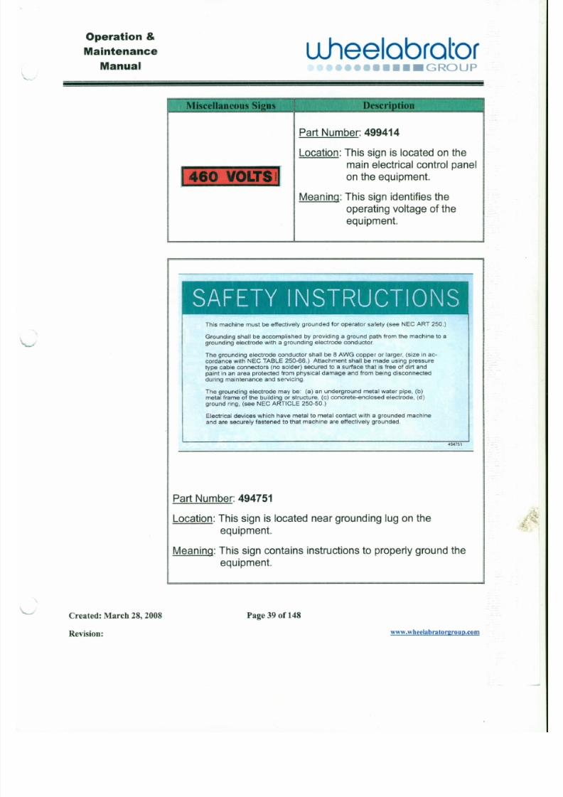
P a r t N u m b e r : 499414
L o c a t io n : T h i s s i g n i s l o c a t e d o n t h e
m a in e l e ct ri c a l c o n t r o l p a n e l
o n t h e e q u i p m e n t .
M e a n i n g : Th i s s i g n i d e n t i f i e s t h eo p e r a t i n g v o l t a g e o f t h e
e q u i p m e n t .
~~ 't~,
4 ,~A - ~- ; . ',~ , . . " -
S A F E TY INS TR U C TIO NSThis machine must be effectively grounded for operator safety (see NEe ART 250.)
Grounding shall beaccomplished by providing a ground path from the machine to a
grounding electrode with agrounding electrode conductor.
The grounding electrode conductor shall be 8 AWG copper or larger, (size in ac-
cordance with NEe TABLE 250-66.) Attachment shall be made using pressure
type cable connectors (no solder) secured to asurface that is free of dirt and
paint inan area protected from physical damage and from being disconnected
during maintenance and servicing.
Operation &
7/30/2019 MANUAL DE USUARIO GRANALLADORA (2).pdf
http://slidepdf.com/reader/full/manual-de-usuario-granalladora-2pdf 44/240
Maintenance
ManualLiheelabrator
•••••• GROUP
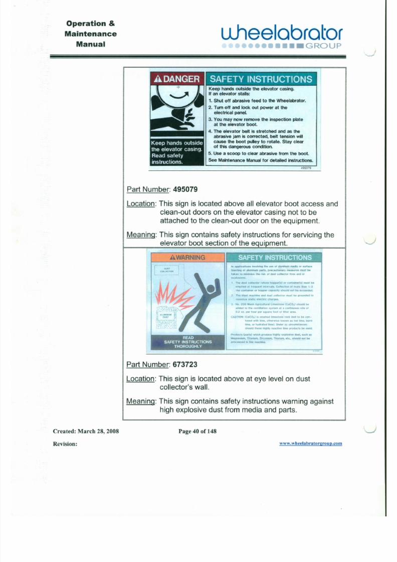
Keep hands outside the elevator casing.If an elevator stalls:
1. Shut off abrasive feed to the Wheelabrator.
2. Tum off and lock out power at theelectrical panel
3. Youmay now remove the inspection plateat the elevator boot.
~ 1 4 . The elevator belt is stretched and as the
~ abrasive jam is corrected, belt tension willcause the boot pulley to rotate. Stay clearof this dangerous condition.
5. Use a scoop to clear abrasive from the boot.
See Maintenance Manual for detailed instructions.
495079
Part Number: 495079
Location: This sign is located above all elevator boot access andclean-out doors on the elevator casing not to be
attached to the clean-out door on the equipment.
Meaning: This sign contains safety instructions for servicing the
elevator boot section of the equipment.
AWARNING
DUST
In appicatons In't'olving theuse ot alumnummedia or surface
blastng of alumnumparts, precauUon8fy rnea.ur •• must be
J
'---.-)
Operation &
7/30/2019 MANUAL DE USUARIO GRANALLADORA (2).pdf
http://slidepdf.com/reader/full/manual-de-usuario-granalladora-2pdf 45/240
Maintenance
Manual
ulleelabrator••• GROUP
Section 4 Blast Wheel
4.1 25 EZEFIT Blast Wheel
4.1.1 How the Blast Wheel Works
&)
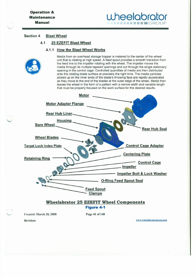
Media from an overhead storage hopper is metered to the center of the wheel
unit that is rotating at high speed. A feed spout provides a smooth transition from
the feed line to the impeller rotating with the wheel. The impeller moves the
media through its multiple tapered openings and out through the single stationary
opening in the control cage. Controlled quantities of media are then distributed
onto the rotating blade surface at precisely the right time. The media particles
picked up on the inner ends of the blade's throwing face are rapidly accelerated
as they move to the end of the blades at the outer edge of the wheel. Media then
leaves the wheel in the form of a pattern with a narrow width and variable length
that must be properly focused on the work surface for the desired results.
Motor
Motor Adapter Flange
- - - - - - - - - - - - - - .Rear Hub Liner
Operation &

7/30/2019 MANUAL DE USUARIO GRANALLADORA (2).pdf
http://slidepdf.com/reader/full/manual-de-usuario-granalladora-2pdf 46/240
Maintenance
Manualuheelabrator
r..",..., •.....•.....••• GROUP
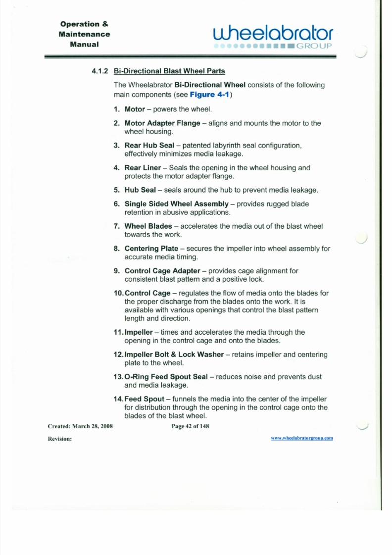
4.1.2 Bi-Directional Blast Wheel Parts
The Wheelabrator Bi-Directional Wheel consists of the following
main components (see Figure 4-1)
1. Motor - powers the wheel.
2. Motor Adapter Flange - aligns and mounts the motor to the
wheel housing.
3. Rear Hub Seal- patented labyrinth seal configuration,
effectively minimizes media leakage.
4. Rear Liner - Seals the opening in the wheel housing and
protects the motor adapter flange.
5. Hub Seal - seals around the hub to prevent media leakage.
6. Single Sided Wheel Assembly - provides rugged bladeretention in abusive applications.
7. Wheel Blades - accelerates the media out of the blast wheel
towards the work.
8. Centering Plate - secures the impeller into wheel assembly for
accurate media timing.
J
Operation &

7/30/2019 MANUAL DE USUARIO GRANALLADORA (2).pdf
http://slidepdf.com/reader/full/manual-de-usuario-granalladora-2pdf 47/240
Maintenance
Manual
uheelobrotor•••••••• GROUP
Section 4 Blast Wheel
4.1 25 EZEFIT Blast Wheel
4.1.1 How the Blast Wheel Works
8
Media from an overhead storage hopper is metered to the center of the wheel
unit that is rotating at high speed. A feed spout provides a smooth transition from
the feed line to the impeller rotating with the wheel. The impeller moves the
media through its multiple tapered openings and out through the single stationary
opening in the control cage. Controlled quantities of media are then distributed
onto the rotating blade surface at precisely the right time. The media particles
picked up on the inner ends of the blade's throwing face are rapidly accelerated
as they move to the end of the blades at the outer edge of the wheel. Media then
leaves the wheel in the form of a pattern with a narrow width and variable length
that must be properly focused on the work surface for the desired results.
Motor
Motor Adapter Flange
- - - - - - - - - - - - - - .Rear Hub Liner
Operation &
7/30/2019 MANUAL DE USUARIO GRANALLADORA (2).pdf
http://slidepdf.com/reader/full/manual-de-usuario-granalladora-2pdf 48/240
Maintenance
ManualLlheelabrator
••• GROUP
4.1.2 Bi-Directional Blast Wheel Parts
The Wheelabrator Bi-Directional Wheel consists of the following
main components (see Figure 4-1)
1. Motor - powers the wheel.
2. Motor Adapter Flange - aligns and mounts the motor to the
wheel housing.
3. Rear Hub Seal- patented labyrinth seal configuration,
effectively minimizes media leakage.
4. Rear Liner - Seals the opening in the wheel housing and
protects the motor adapter flange.
5. Hub Seal- seals around the hub to prevent media leakage.
6. Single Sided Wheel Assembly - provides rugged bladeretention in abusive applications.
7. Wheel Blades - accelerates the media out of the blast wheel
towards the work.
8. Centering Plate - secures the impeller into wheel assembly for
accurate media timing.
J
Operation &

7/30/2019 MANUAL DE USUARIO GRANALLADORA (2).pdf
http://slidepdf.com/reader/full/manual-de-usuario-granalladora-2pdf 49/240
Maintenance
Manualuheelobrctor
•••• GROUP
Section 4 Blast Wheel
4.1 25 EZEFIT BlastWheel
4.1.1 How the Blast Wheel Works
8
Media from an overhead storage hopper is metered to the center of the wheel
unit that is rotating at high speed. A feed spout provides a smooth transition from
the feed line to the impeller rotating with the wheel. The impeller moves the
media through its multiple tapered openings and out through the single stationary
opening in the control cage. Controlled quantities of media are then distributed
onto the rotating blade surface at precisely the right time. The media particles
picked up on the inner ends of the blade's throwing face are rapidly accelerated
as they move to the end of the blades at the outer edge of the wheel. Media then
leaves the wheel in the form of a pattern with a narrow width and variable length
that must be properly focused on the work surface for the desired results.
Motor
Motor Adapter Flange
- - - - - - - - - - - - - - .Rear Hub Liner
Operation &

7/30/2019 MANUAL DE USUARIO GRANALLADORA (2).pdf
http://slidepdf.com/reader/full/manual-de-usuario-granalladora-2pdf 50/240
Maintenance
Manual
u.heelabrator••• GROUP
4.1.2 Bi·Directional Blast Wheel Parts
The Wheelabrator Bl-Dlrectlonal Wheel consists of the following
main components (see Figure 4-1)
1. Motor - powers the wheel.
2. Motor Adapter Flange - aligns and mounts the motor to the
wheel housing.
3. Rear Hub Seal- patented labyrinth seal configuration,
effectively minimizes media leakage.
4. Rear Liner - Seals the opening in the wheel housing and
protects the motor adapter flange.
5. Hub Seal - seals around the hub to prevent media leakage.
6. Single Sided Wheel Assembly - provides rugged bladeretention in abusive applications.
7. Wheel Blades - accelerates the media out of the blast wheel
towards the work.
8. Centering Plate - secures the impeller into wheel assembly for
accurate media timing.
J
Operation &

7/30/2019 MANUAL DE USUARIO GRANALLADORA (2).pdf
http://slidepdf.com/reader/full/manual-de-usuario-granalladora-2pdf 51/240
Maintenance
Manual
uheelabrator•••••••• GROUP
\.......- '
Section 4 Blast Wheel
4.1 25 EZEFIT Blast Wheel
4.1.1 How the Blast Wheel Works
&)
Media from an overhead storage hopper is metered to the center of the wheel
unit that is rotating at high speed. A feed spout provides a smooth transition from
the feed line to the impeller rotating with the wheel. The impeller moves the
media through its multiple tapered openings and out through the single stationary
opening in the control cage. Controlled quantities of media are then distributed
onto the rotating blade surface at precisely the right time. The media particles
picked up on the inner ends of the blade's throwing face are rapidly accelerated
as they move to the end of the blades at the outer edge of the wheel. Media then
leaves the wheel in the form of a pattern with a narrow width and variable length
that must be properly focused on the work surface for the desired results.
Motor
Motor Adapter Flange - - - - - - - - - - - - .Rear Hub Liner
Operation&
7/30/2019 MANUAL DE USUARIO GRANALLADORA (2).pdf
http://slidepdf.com/reader/full/manual-de-usuario-granalladora-2pdf 52/240
Maintenance
Manualuheelobrotor
rv rv r-; , •••• GROUPv
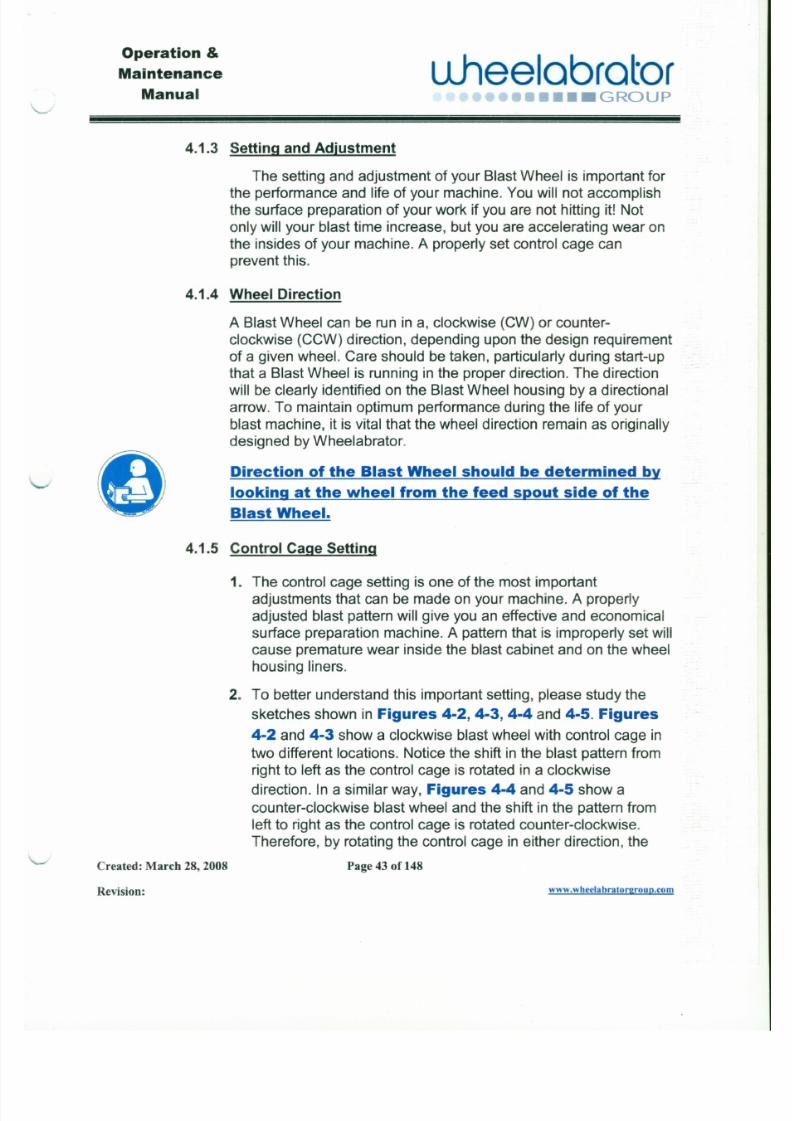
4.1.3 Setting and Adjustment
The setting and adjustment of your Blast Wheel is important for
the performance and life of your machine. You will not accomplish
the surface preparation of your work if you are not hitting it! Not
only will your blast time increase, but you are accelerating wear on
the insides of your machine. A properly set control cage can
prevent this.
o
4.1.4 Wheel Direction
A Blast Wheel can be run in a, clockwise (CW) or counter-
clockwise (CCW) direction, depending upon the design requirement
of a given wheel. Care should be taken, particularly during start-up
that a Blast Wheel is running in the proper direction. The direction
will be clearly identified on the Blast Wheel housing by a directional
arrow. To maintain optimum performance during the life of yourblast machine, it is vital that the wheel direction remain as originally
designed byWheelabrator.
Direction of the BlastWheel should bedetermined by
looking at thewheel from the feed spout side of the
BlastWheel.
Operation &
7/30/2019 MANUAL DE USUARIO GRANALLADORA (2).pdf
http://slidepdf.com/reader/full/manual-de-usuario-granalladora-2pdf 53/240
Maintenance
Manual
u.heelabrator•••• C•••• GROUP
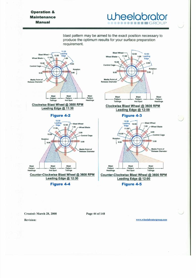
blast pattern may be aimed to the exact position necessary toproduce the optimum results for your surface preparationrequirement.
WheelBlade
9:00$43«(
MediaPointof
ReleaseDiameter
£ ~ i I I ! / l rL Blast I Blast I I Blast
Pattern-L-Pattern~ Pattern
Tailings HotSpot Headings
Clockwise Blast Wheel @ 3600RPMLeading Edge@ 11:30
Figure 4-2
WheelBlade
) 1 f 1 r . Rotation3:00 I
,j~
MediaPointof...../. I .~t,:\Release Diameter -:~.'~~~~~~\
~ , p % ; ; t [ " l f . l } ,Llast I Blast I I Blast
Pattern-L Pattern-U-attern
Tailings HotSpot Headings
9 : 0 ~ « - f
Clockwise Blast Wheel @ 3600 RPM
Leading Edge @ 12:00
Figure 4-3
WheelBlade
J
J
Operation &
7/30/2019 MANUAL DE USUARIO GRANALLADORA (2).pdf
http://slidepdf.com/reader/full/manual-de-usuario-granalladora-2pdf 54/240
Maintenance
Manual\.J
uheelobrotor••••• GROUP
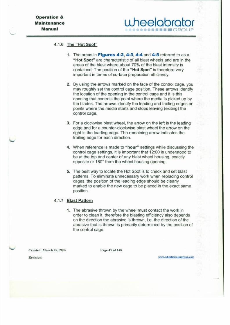
4.1.6 The "Hot Spot"
1. The areas in Figures 4-2, 4-3, 4-4 and 4-5 referred to as a
"Hot Spot" are characteristic of all blast wheels and are in the
areas of the blast where about 70% of the blast intensity is
contained. The position of the "Hot Spot" is therefore very
important in terms of surface preparation efficiency.
2. By using the arrows marked on the face of the control cage, you
may roughly set the control cage position. These arrows identify
the location of the opening in the control cage and it is this
opening that controls the point where the media is picked up by
the blades. The arrows identify the leading and trailing edges or
points where the media starts and stops leaving (exiting) the
control cage.
3. For a clockwise blast wheel, the arrow on the left is the leading
edge and for a counter-clockwise blast wheel the arrow on the
right is the leading edge. The remaining arrow indicates the
trailing edge for each direction.
4. When reference is made to "hour" settings while discussing the
control cage settings, it is important that 12:00 is understood to
Operation &
7/30/2019 MANUAL DE USUARIO GRANALLADORA (2).pdf
http://slidepdf.com/reader/full/manual-de-usuario-granalladora-2pdf 55/240
J
Maintenance
Manualuheelabrator
•••• GROUP
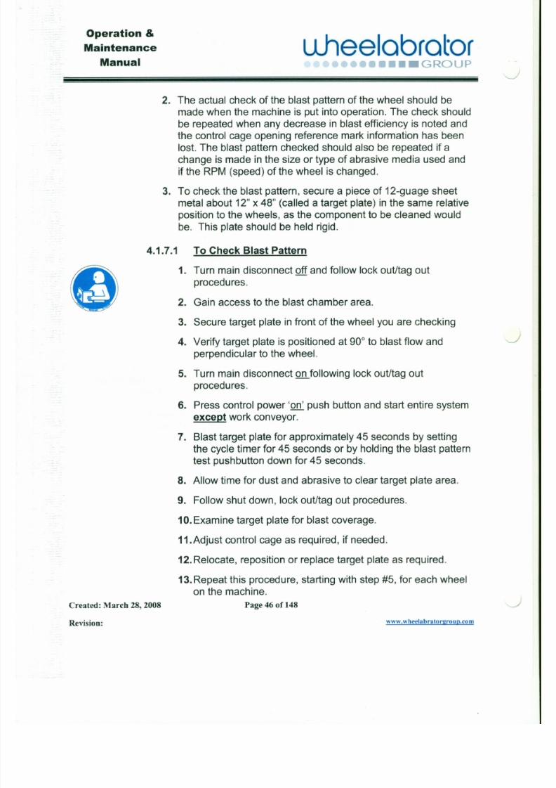
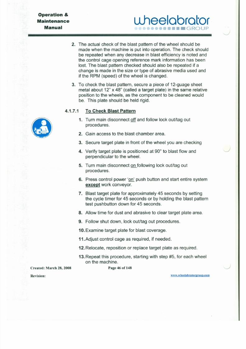
2. The actual check of the blast pattern of the wheel should bemade when the machine is put into operation. The check should
be repeated when any decrease in blast efficiency is noted and
the control cage opening reference mark information has been
lost. The blast pattern checked should also be repeated if a
change is made in the size or type of abrasive media used and
if the RPM (speed) of the wheel is changed.
3. To check the blast pattern, secure a piece of 12-guage sheet
metal about 12" x 48" (called a target plate) in the same relative
position to the wheels, as the component to be cleaned would
be. This plate should be held rigid.
4.1.7.1 To Check Blast Pattern
&)1. Turn main disconnect off and follow lock out/tag out
procedures.
2. Gain access to the blast chamber area.
3. Secure target plate in front of the wheel you are checking
4. Verify target plate is positioned at 90° to blast flow and ,J
perpendicular to the wheel.
5. Turn main disconnect on following lock out/tag out
Operation &
7/30/2019 MANUAL DE USUARIO GRANALLADORA (2).pdf
http://slidepdf.com/reader/full/manual-de-usuario-granalladora-2pdf 56/240
Maintenance
Manualuheelobrotor
•••• GROUP
4.1.6 The "Hot Spot"
1. The areas in Figures 4-2, 4-3, 4-4 and 4-5 referred to as a
"Hot Spot" are characteristic of all blast wheels and are in the
areas of the blast where about 70% of the blast intensity is
contained. The position of the "Hot Spot" is therefore very
important in terms of surface preparation efficiency.
2. By using the arrows marked on the face of the control cage, you
may roughly set the control cage position. These arrows identify
the location of the opening in the control cage and it is this
opening that controls the point where the media is picked up by
the blades. The arrows identify the leading and trailing edges or
points where the media starts and stops leaving (exiting) the
control cage.
3. For a clockwise blast wheel, the arrow on the left is the leading
edge and for a counter-clockwise blast wheel the arrow on the
right is the leading edge. The remaining arrow indicates the
trailing edge for each direction.
4. When reference is made to "hour" settings while discussing the
control cage settings, it is important that 12:00 is understood to
Operation &
Maintenance
7/30/2019 MANUAL DE USUARIO GRANALLADORA (2).pdf
http://slidepdf.com/reader/full/manual-de-usuario-granalladora-2pdf 57/240
J
Manualuheelabrator
•••• GROUP
2. The actual check of the blast pattern of the wheel should bemade when the machine is put into operation. The check should
be repeated when any decrease in blast efficiency is noted and
the control cage opening reference mark information has been
lost. The blast pattern checked should also be repeated if a
change is made in the size or type of abrasive media used and
if the RPM (speed) of the wheel is changed.
3. To check the blast pattern, secure a piece of 12-guage sheet
metal about 12" x 48" (called a target plate) in the same relative
position to the wheels, as the component to be cleaned would
be. This plate should be held rigid.
4.1.7.1 To Check Blast Pattern
81. Turn main disconnect off and follow lock out/tag out
procedures.
2. Gain access to the blast chamber area.
3. Secure target plate in front of the wheel you are checking
4. Verify target plate is positioned at 90° to blast flow and J
perpendicular to the wheel.
5. Turn main disconnect on following lock out/tag out
Operation &
7/30/2019 MANUAL DE USUARIO GRANALLADORA (2).pdf
http://slidepdf.com/reader/full/manual-de-usuario-granalladora-2pdf 58/240
Maintenance
Manualu.heelabrator
•••• GROUP~
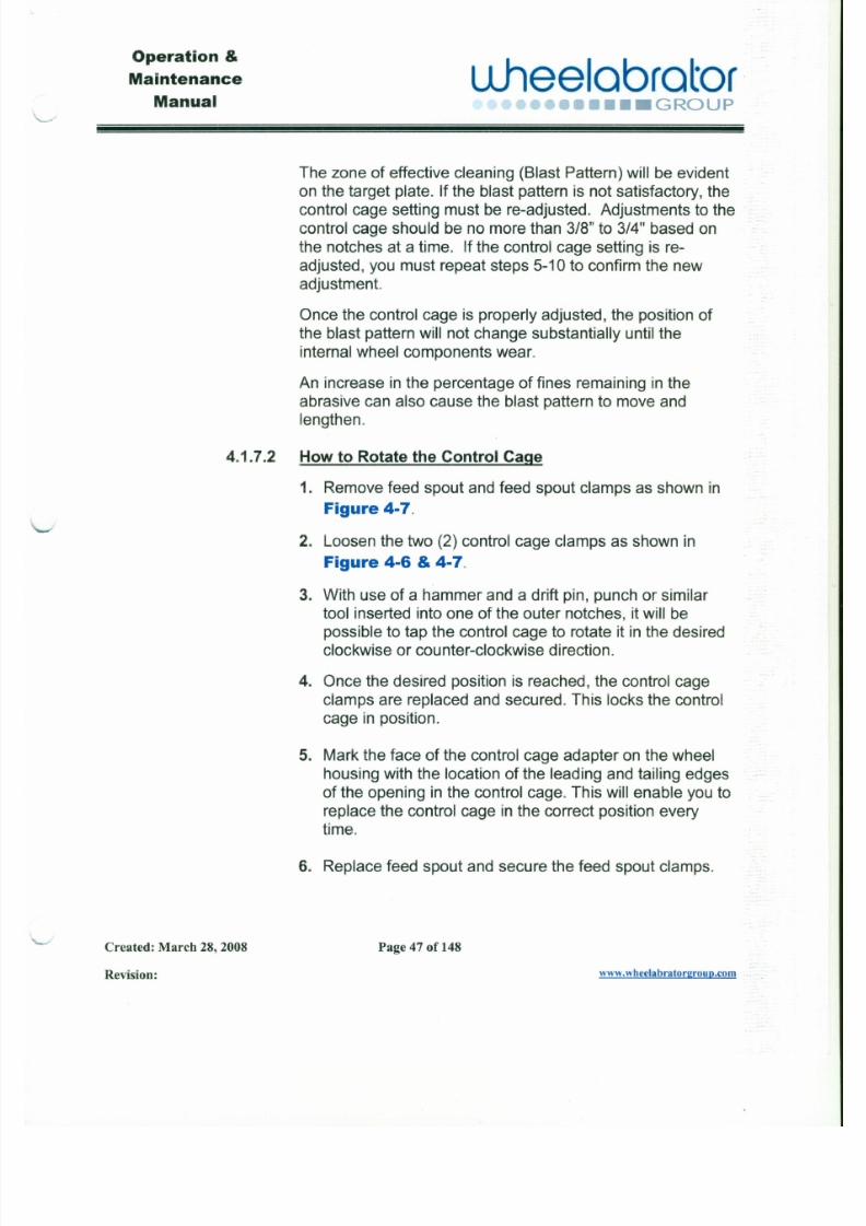
The zone of effective cleaning (Blast Pattern) will be evident
on the target plate. If the blast pattern is not satisfactory, the
control cage setting must be re-adjusted. Adjustments to the
control cage should be no more than 3/8" to 3/4" based on
the notches at a time. If the control cage setting is re-
adjusted, you must repeat steps 5-10 to confirm the newadjustment.
Once the control cage is properly adjusted, the position of
the blast pattern will not change substantially until the
internal wheel components wear.
An increase in the percentage of fines remaining in the
abrasive can also cause the blast pattern to move and
lengthen.
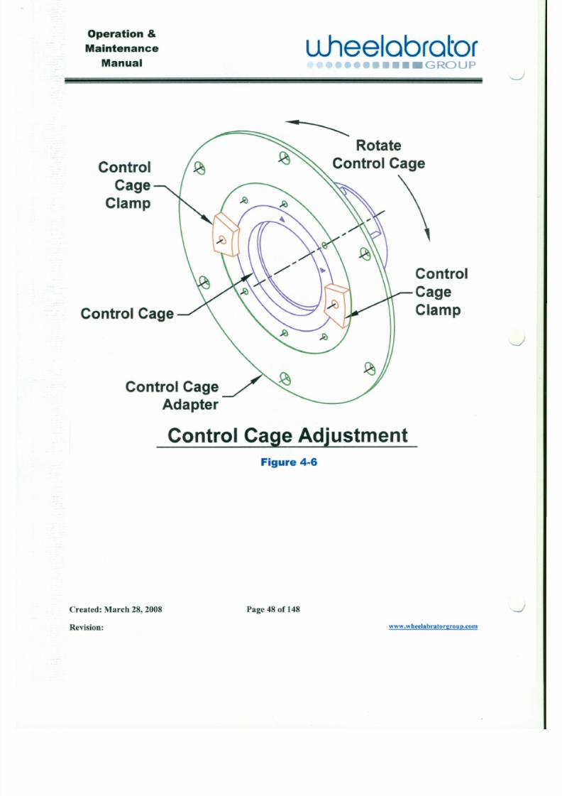
4.1.7.2 HowtoRotatetheControl Cage
1. Remove feed spout and feed spout clamps as shown in
Figure4-7.
2. Loosen the two (2) control cage clamps as shown in
Figure 4-6&4-7.
Operation &
Maintenance
7/30/2019 MANUAL DE USUARIO GRANALLADORA (2).pdf
http://slidepdf.com/reader/full/manual-de-usuario-granalladora-2pdf 59/240
Manual
L 1 h e e l a b r a t o r•••• GROUP
Control
Cage
Clamp
~
Rotate
Control Cage
Control Cage
Control
CageClamp
J
Operation &
Maintenance
7/30/2019 MANUAL DE USUARIO GRANALLADORA (2).pdf
http://slidepdf.com/reader/full/manual-de-usuario-granalladora-2pdf 60/240
Manual
L l h e e l a b r a t o r•••••••••• GROUP
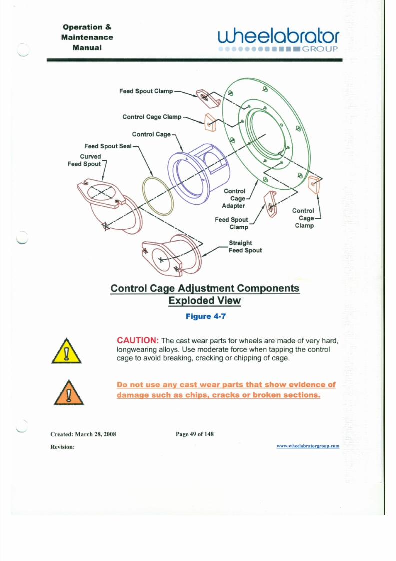
FeedSpoutSeal
Curved
FeedSpout
FeedSpoutClamp
Control CageClamp
Control Cage
~
contrOlfl .•Cage .•~
Adapter Control
CageFeedSpout Clamp
Clamp
Straight
FeedSpout
Operation &
Maintenance

7/30/2019 MANUAL DE USUARIO GRANALLADORA (2).pdf
http://slidepdf.com/reader/full/manual-de-usuario-granalladora-2pdf 61/240
Manualuheeloorotor
••••• GROUP
Section5 MediaHandlingSystem
5.1 Functionof theLowerReclaim:
The lower reclaim function is to collect contaminants spent media
thrown by the blast wheels. The media and contaminants are then
delivered by the lower reclaim to the bucket elevator boot section. The
lower reclaim is part of a total media recovery system to clean and
recycle media back to the blast wheel.
5.1.1 Typesof LowerReclaims:
5.1.1.1 FullGravityReclaims:
a. Gravity hoppers are used for directing spent media
directly to the bucket elevator boot section.
b. Gravity hoppers are generally used on small equipment.
c. There are no drives or mechanical moving parts in gravity
reclaims.
5.1.1.2 LowerScrewConveyorReclaims:
Operation &
Maintenance L1heelabrator

7/30/2019 MANUAL DE USUARIO GRANALLADORA (2).pdf
http://slidepdf.com/reader/full/manual-de-usuario-granalladora-2pdf 62/240
Manual •••• GROUP
Gearmotor
Adapter Plate
Gearmotor
Drive Shaft
Bearing
Shaft Seal
Screw Adapter Housing
Screw Conveyor Trough
Screw Conveyor
End Shaft
Shaft Seal
Bearing
illical Lower Screw Conveyor Components
Figure 5-1
J
Operation &
Maintenance ulleelabrator
7/30/2019 MANUAL DE USUARIO GRANALLADORA (2).pdf
http://slidepdf.com/reader/full/manual-de-usuario-granalladora-2pdf 63/240
Manual •••• GROUP
Section 5 MediaHandling System
5.1 Function of the Lower Reclaim:
The lower reclaim function is to collect contaminants spent media
thrown by the blast wheels. The media and contaminants are then
delivered by the lower reclaim to the bucket elevator boot section. The
lower reclaim is part of a total media recovery system to clean and
recycle media back to the blast wheel.
5.1.1 Types of Lower Reclaims:
5.1.1.1 Full Gravity Reclaims:
a. Gravity hoppers are used for directing spent media
directly to the bucket elevator boot section.
b. Gravity hoppers are generally used on small equipment.
c. There are no drives or mechanical moving parts in gravity
reclaims.
5.1.1.2 Lower Screw Conveyor Reclaims:
Operation &
Maintenance L l h e e l a b r a t o r
7/30/2019 MANUAL DE USUARIO GRANALLADORA (2).pdf
http://slidepdf.com/reader/full/manual-de-usuario-granalladora-2pdf 64/240
Manual ••••••••• GROUP
' - . . . . -
4. Screw Adapter Housing - joins the screw conveyortrough to the elevator boot or cabinet. This may not
be required on all applications.
5. Drive Shaft - fixed to the screw conveyor and
mounted through the bearing to drive the conveyor.
6. End Shaft - fixed to the screw conveyor and mounted
through the bearing to support the conveyor oppositethe drive.
7. Shaft Seals - prevents media leaking out the ends of
the conveyor and protects the bearings from the
media. (see Figures 5-2 & 5-3)
8. Bearings - supports ends of the screw conveyor.
9. Bearing Adapter Plate - closes the end of the
conveyor and supports the bearing.
10. Gearmotor Adapter Plate - closes the end of the
conveyor and supports the bearing and Gearmotor.
Operation &
Maintenance Llheelabrator
7/30/2019 MANUAL DE USUARIO GRANALLADORA (2).pdf
http://slidepdf.com/reader/full/manual-de-usuario-granalladora-2pdf 65/240
Manual •• GROUP
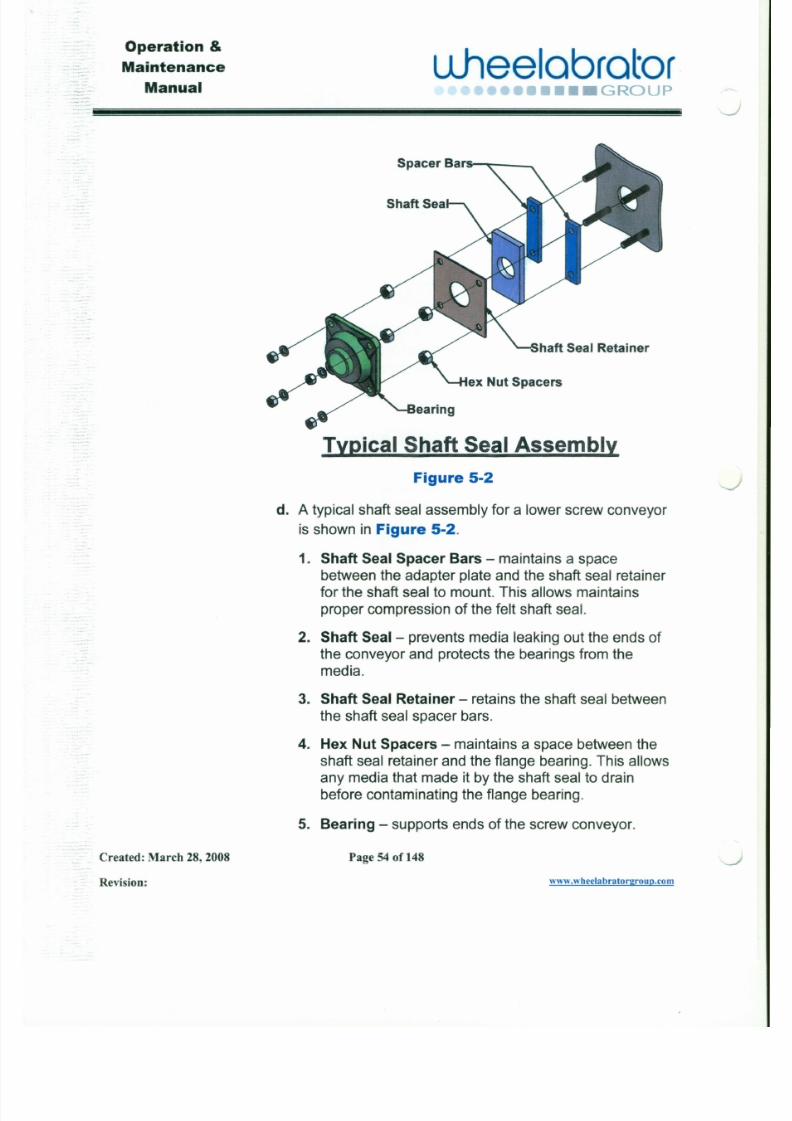
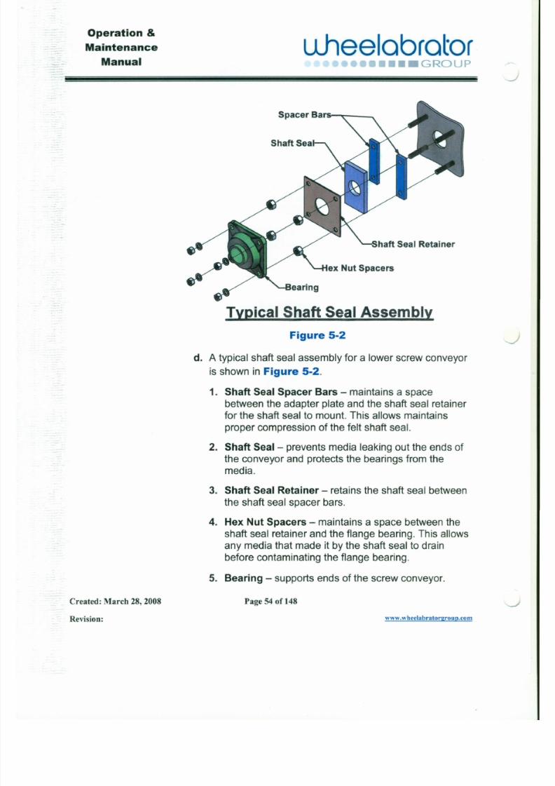
Spacer Bars < _
!mical ShaftSealAssembly
Figure 5-2
d. A typical shaft seal assembly for a lower screw conveyor
is shown in Figure 5-2.
J
J
Operation &
Maintenance uheelcorotor

7/30/2019 MANUAL DE USUARIO GRANALLADORA (2).pdf
http://slidepdf.com/reader/full/manual-de-usuario-granalladora-2pdf 66/240
Manual •••• GROUP'\.......-
4. Screw Adapter Housing - joins the screw conveyortrough to the elevator boot or cabinet. This may not
be required on all applications.
5. Drive Shaft - fixed to the screw conveyor and
mounted through the bearing to drive the conveyor.
6. End Shaft - fixed to the screw conveyor and mounted
through the bearing to support the conveyor oppositethe drive.
7. Shaft Seals - prevents media leaking out the ends of
the conveyor and protects the bearings from the
media. (see Figures 5-2& 5-3)
8. Bearings - supports ends of the screw conveyor.
9. Bearing Adapter Plate - closes the end of the
conveyor and supports the bearing.
10. Gearmotor Adapter Plate - closes the end of the
conveyor and supports the bearing and Gearmotor.
Operation &
Maintenance uheelobrotor
7/30/2019 MANUAL DE USUARIO GRANALLADORA (2).pdf
http://slidepdf.com/reader/full/manual-de-usuario-granalladora-2pdf 67/240
Manual .( n•• GROUP
Spacer Bars < _
Imical ShaftSealAssembly
Figure 5-2
d. A typical shaft seal assembly for a lower screw conveyor
is shown in Figure 5-2.
J
J
Operation &
Maintenance uheelobrotor
7/30/2019 MANUAL DE USUARIO GRANALLADORA (2).pdf
http://slidepdf.com/reader/full/manual-de-usuario-granalladora-2pdf 68/240
Manual •••• GROUP
Bearing Mounting Plat,
UHMW Shot Dis
v Bearing Spacers
Imical Shaft Seal Assembl'l.
Figure 5·3
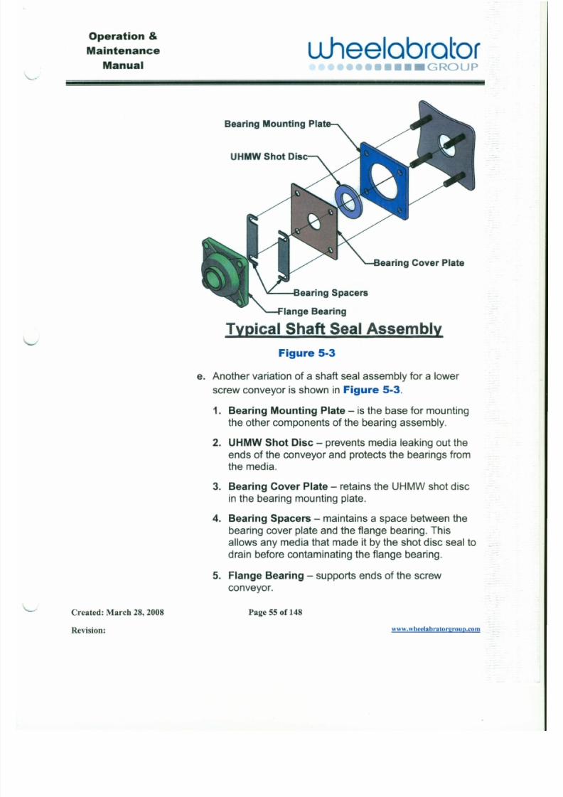
e. Another variation of a shaft seal assembly for a lower
Operation &
Maintenance Llheelabrator
7/30/2019 MANUAL DE USUARIO GRANALLADORA (2).pdf
http://slidepdf.com/reader/full/manual-de-usuario-granalladora-2pdf 69/240
Manual •••• GROUP
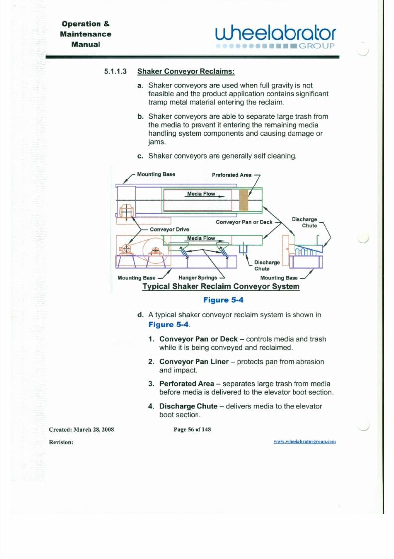
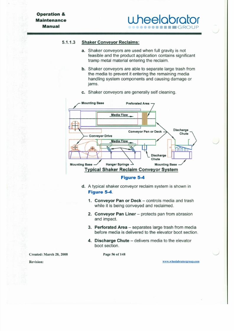
5.1.1.3 Shaker Conveyor Reclaims:
a. Shaker conveyors are used when full gravity is not
feasible and the product application contains significant
tramp metal material entering the reclaim.
b. Shaker conveyors are able to separate large trash from
the media to prevent it entering the remaining media
handling system components and causing damage or
jams.
c. Shaker conveyors are generally self cleaning.
Mounting Base Preforated Area
Media Flow.
-~
J
Operation &
Maintenance uheelobrotor

7/30/2019 MANUAL DE USUARIO GRANALLADORA (2).pdf
http://slidepdf.com/reader/full/manual-de-usuario-granalladora-2pdf 70/240
Manual-:
••••••••• GROUP
Bearing Mounting Plat,
UHMW Shot Cis
v Bearing Spacers
illical Shaft SealAssemblx
Figure 5-3
e. Another variation of a shaft seal assembly for a lower
Operation &
Maintenance
Manualuheelobrotor
7/30/2019 MANUAL DE USUARIO GRANALLADORA (2).pdf
http://slidepdf.com/reader/full/manual-de-usuario-granalladora-2pdf 71/240
•••• GROUP
5.1.1.3 Shaker Conveyor Reclaims:
a. Shaker conveyors are used when full gravity is not
feasible and the product application contains significant
tramp metal material entering the reclaim.
b. Shaker conveyors are able to separate large trash from
the media to prevent it entering the remaining media
handling system components and causing damage or
jams.
c. Shaker conveyors are generally self cleaning.
Mounting Base Preforated Area
Media Flow ••
'--J
J
Operation &
Maintenance u .hee lab ra to r
7/30/2019 MANUAL DE USUARIO GRANALLADORA (2).pdf
http://slidepdf.com/reader/full/manual-de-usuario-granalladora-2pdf 72/240
Manual •••• GROUP
5. Mounting Base - supports the shaker conveyor andsecures it to the foundation.
6. Hanger Springs - are sized to control stroke,frequency and angle of attack designed to proper
conveying action for type media.
7. Conveyor Dr ive - powers the shaker conveyor.
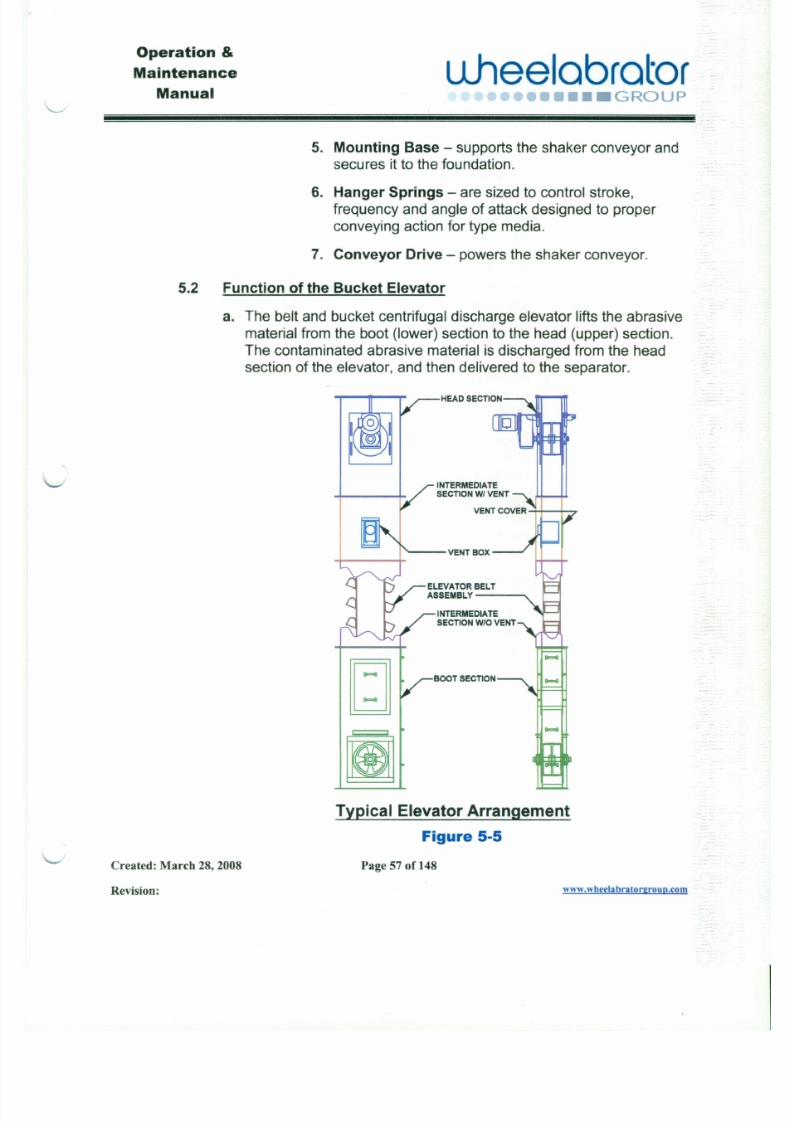
5.2 Function of the Bucket Elevator
a. The belt and bucket centrifugal discharge elevator lifts the abrasive
material from the boot (lower) section to the head (upper) section.The contaminated abrasive material is discharged from the headsection of the elevator, and then delivered to the separator.
INTERMEDIATESECTION WI VENT
Operation &
u .hee lab ra to raintenance
Manual r-, ,-.. ~ ....,·••• GROUP

7/30/2019 MANUAL DE USUARIO GRANALLADORA (2).pdf
http://slidepdf.com/reader/full/manual-de-usuario-granalladora-2pdf 73/240
J
b. A typical elevator arrangement is shown in Figure 5-5.
1. Head Section - This is the upper section of the bucket elevatorcasing. It usually contains the elevator drive.
2. Intermediate Section with Vent - This is the part of theelevator casing that contains the vent box.
3. Vent Box - This is the outlet to remove the dust from of the
elevator casing. It can usually be mounted on either side of theintermediate section depending on the vent piping requirement.
4. Vent Cover - Covers the opening in the intermediate section
opposite the vent box when part of design.
5. Intermediate Section without Vent - This is the part of the
elevator casing used to increase the height of the elevator. This
section is not always required.6. Boot Section - This is the lower section of the bucket elevator
casing. This section receives the spent media from the blastchamber and lower reclaim.
J
7. Elevator Belt Assembly - This bucket and belt assembly
transports the abrasive media from the boot section to the headsection and discharges it to the upper reclaim system.
Operation &
Maintenance
Manualu.heelabrator
7/30/2019 MANUAL DE USUARIO GRANALLADORA (2).pdf
http://slidepdf.com/reader/full/manual-de-usuario-granalladora-2pdf 74/240
.Lvv ••••• GROUP
Shedder (only somedesigns)/ TopCover \
~ TakeUpBolt ,\, j
Shaft
Pulley', IIh
Gearmotor
Bearing &ShaftSeal I III I III '
TakeUpAssembly l I I I I I '
Weldment
IYPical HeadSection ArrangementFigure 5-6
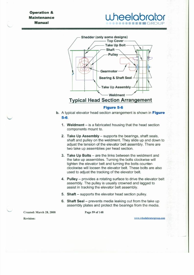
b. A typical elevator head section arrangement is shown in Figure
5-6.
1. Weldment - is a fabricated housing that the head section
components mount to.
Operation &
Maintenance
ManualWleelabrator
•••• GROUP
7/30/2019 MANUAL DE USUARIO GRANALLADORA (2).pdf
http://slidepdf.com/reader/full/manual-de-usuario-granalladora-2pdf 75/240
7. Bearing - supports ends of the elevator head section shaft.
8. Gearmotor - is mounted to the head section shaft to powerthe elevator.
9. Top Cover - is the access cover to the elevator headsection and a safety cover to guard against the rotatingcomponents inside the elevator head section weldment.
10. Shedder - is a wear component to assist in delivery ofabrasive media and contaminants to the upper reclaim
system. This is only used on some designs of elevator head
sections.
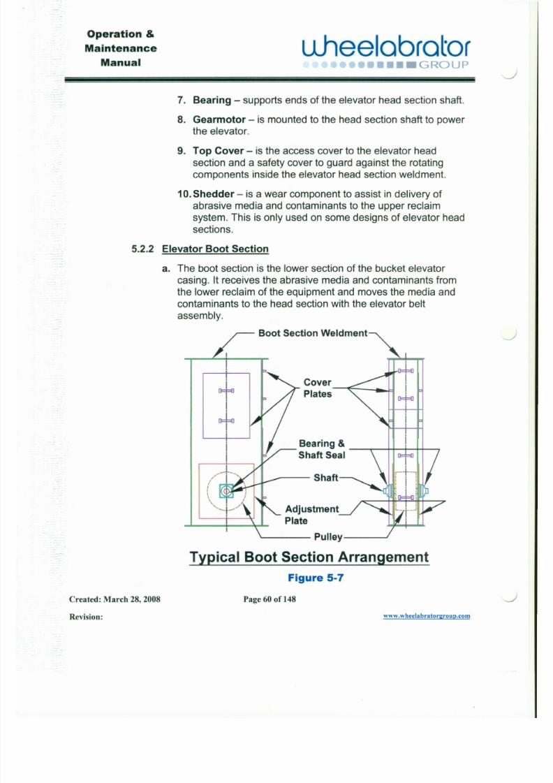
5.2.2 Elevator Boot Section
a. The boot section is the lower section of the bucket elevator
casing. It receives the abrasive media and contaminants from
the lower reclaim of the equipment and moves the media andcontaminants to the head section with the elevator belt
assembly.
Boot Section Weldment
J
J
Operation &
Maintenance
ManualLlheelabrator
7/30/2019 MANUAL DE USUARIO GRANALLADORA (2).pdf
http://slidepdf.com/reader/full/manual-de-usuario-granalladora-2pdf 76/240
•••• GROUP
b. A typical elevator boot section arrangement is shown in Figure5-7.
1. Boot Section Weldment - is a fabricated housing that the
boot section components mount to.
2. Adjustment Plate - supports the bearings, shaft seals, shaftand pulley on the boot section weldment. There are usually
two of these plates per boot section.
3. Pulley - provides a rotating surface for the elevator beltassembly to ride on.
4. Shaft - supports the elevator boot section pulley.
5. Shaft Seal - prevents media leaking around the shaft and
protects the bearings from the media.
6. Bearing - supports ends of the elevator boot section shaft.
Note: SeeSection 5.1.1.2(d&e) for the two
types of typical shaft seal assemblies. Also see
Operation &
Maintenance
Manualuheelabrator
••• GROUP
7/30/2019 MANUAL DE USUARIO GRANALLADORA (2).pdf
http://slidepdf.com/reader/full/manual-de-usuario-granalladora-2pdf 77/240
Elevator Bolt&NutBuckets
Typical Elevator Belt Assembly
with Dutchman SpliceTypical Elevator Belt Assembly
with Oil Well Splice
Figure 5-9igure 5-8
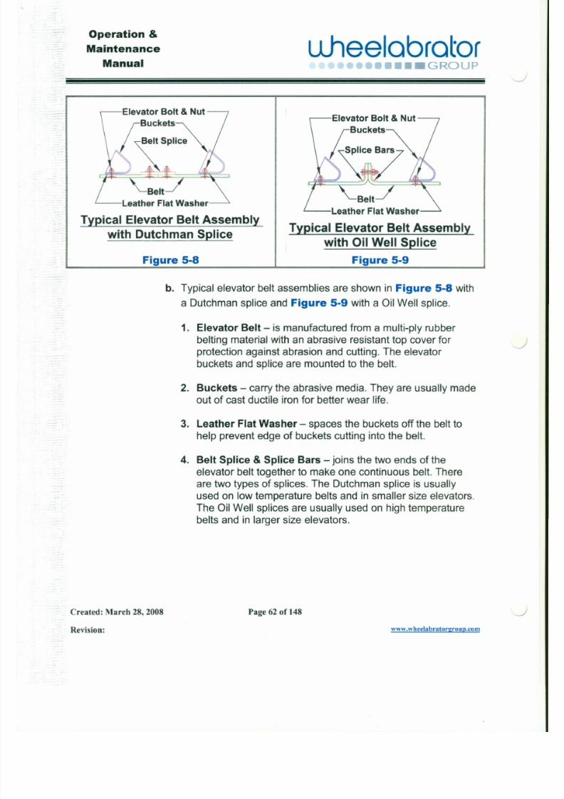
b. Typical elevator belt assemblies are shown in Figure 5-8with
a Dutchman splice and Figure 5-9with a Oil Well splice.
1. Elevator Belt - is manufactured from a multi-ply rubberbelting material with an abrasive resistant top cover forprotection against abrasion and cutting. The elevatorbuckets and splice are mounted to the belt.
J
J
Operation &
Maintenance
Manual
L lhee lab ra to r
7/30/2019 MANUAL DE USUARIO GRANALLADORA (2).pdf
http://slidepdf.com/reader/full/manual-de-usuario-granalladora-2pdf 78/240
•••• GROUPx..>
5.3 Functions of Upper Reclaims
The upper reclaim function is to collect media and contaminants
delivered from the elevator. Media and contaminants are then
conveyed by the upper reclaim to the media separator. The upperreclaim is a part of a total media recovery system to clean and recyclemedia back to the blast wheel.
5.3.1 Types of Upper Reclaims:
5.3.1.1 Full Gravity Reclaims
a. Gravity reclaims are used for transferring media directlyfrom the elevator head section to the separator.
b. There are no drives in upper gravity reclaims.
5.3.1.2 Upper Screw Conveyor Reclaims
a. Upper screw conveyors are used to reduce systemheight when full gravity is not feasible.
Operation &
Maintenance
Manual
u .hee lab ra to r,..,••• GROUP
7/30/2019 MANUAL DE USUARIO GRANALLADORA (2).pdf
http://slidepdf.com/reader/full/manual-de-usuario-granalladora-2pdf 79/240
Geannotor
AdapterPlate
ScrewAdapterHousing
ScrewConveyorTrough
Separator
ScrewConveyor TrashChute
Bearing
EndShaft
Ref.Separator
I I
~ - - - - - - - - - - - - - - - - - - - - - - - - - - - ~TrashTubing
Typical Upper Screw Conveyor Components
Figure 5-10
ScrewAdapterHousing
ScrewConveyorTrough
Separator
J
J
Operation &
Maintenance
Manual
u.heelabrator•••• GROUP
7/30/2019 MANUAL DE USUARIO GRANALLADORA (2).pdf
http://slidepdf.com/reader/full/manual-de-usuario-granalladora-2pdf 80/240
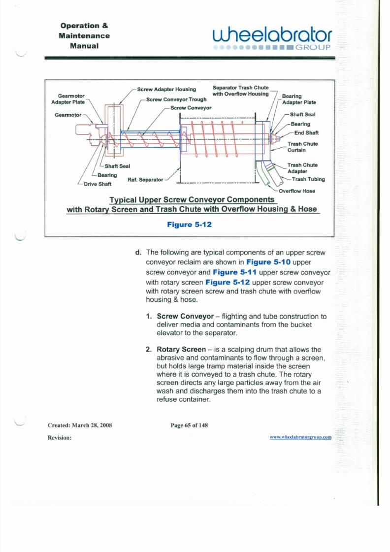
Screw Adapter Housing Separator Trash Chute
with Overflow Housing
Screw Conveyor Trough
ScrewConveyor
Bearing
End Shaft
Trash Chute
Adapter
Trash Tubing
Typical Upper Screw Conveyor Components
with Rotary Screen and Trash Chute with Overflow Housing &Hose
Figure 5-12
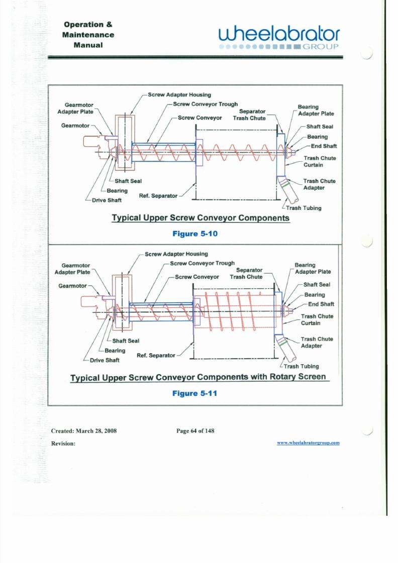
d. The following are typical components of an upper screw
conveyor reclaim are shown in Figure 5-10 upper
Operation &
LLheelabratoraintenance..-
Manual '.~••••••••• GROUP- .. .

7/30/2019 MANUAL DE USUARIO GRANALLADORA (2).pdf
http://slidepdf.com/reader/full/manual-de-usuario-granalladora-2pdf 81/240
J
. .. 3. Screw Conveyor Trough - connects and encloses
the screw conveyor between the bucket elevator andthe separator.
4. Screw Adapter Housing - joins the screw conveyor
trough to the elevator head section.
5. Separator Trash Chute - the rotary screen emptiesthe large trapped particles into this housing.
6. Separator Trash Chute with Overflow Housing-
when there is a surge of media the media isoverflowed into the first compartment of the housing.The rotary screen empties the large trapped particlesinto the second compartment of the housing.
7. Overflow Hose - directs the overflow media back tolower reclaim to be recycled.
8. Trash Chute Curtain - allows access to clean outany trapped particles that are clogging the entrance to ' - o Jthe trash tube.
Warning: DONOT clean out separator trash
Operation &
Maintenance
Manual
uJ lee lab ra to r ~ i ~ ~••••• GROUP -

7/30/2019 MANUAL DE USUARIO GRANALLADORA (2).pdf
http://slidepdf.com/reader/full/manual-de-usuario-granalladora-2pdf 82/240
<.;
13. Shaf t Seals - prevents media leaking out the ends ofthe conveyor and protects the bearings from themedia.
14. Bearings - supports both ends of the screw
conveyor.
15. Bearing Adapter Plate - mounts to the separator
trash chute for mounting the bearing. _
16. Gearmotor Adapter Plate - closes the end of the
conveyor and for mounting the bearing and
gearmotor.
17. Gearmotor - mounted on drive shaft to power screwconveyor.
Operation &
Maintenance
Manualuheelobrotor
o ••• GROUP-

7/30/2019 MANUAL DE USUARIO GRANALLADORA (2).pdf
http://slidepdf.com/reader/full/manual-de-usuario-granalladora-2pdf 83/240
-
SpacerBars" _
-
illical ShaftSeal Assembly
Figure 5-13
e. A typical shaft seal assembly for an upper screw
conveyor is shown in Figure 5-13.
J
J
Operation &
Maintenance
Manual
u .hee lab ra to r••••••••• GROUP
7/30/2019 MANUAL DE USUARIO GRANALLADORA (2).pdf
http://slidepdf.com/reader/full/manual-de-usuario-granalladora-2pdf 84/240
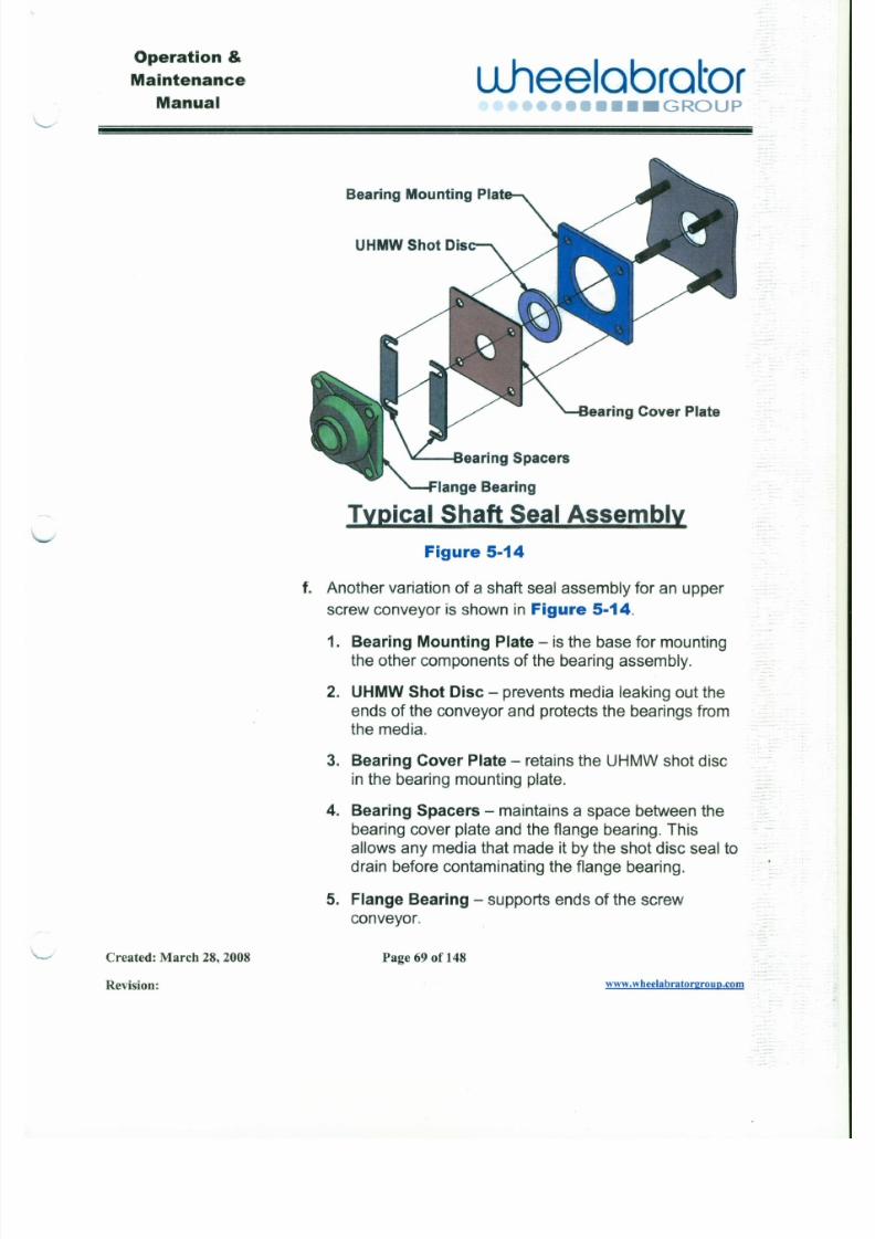
Bearing Mounting Plat
UHMW Shot Dis
v tsearing Spacers
.!mical Shaft Seal Assembly
Figure 5-14
f. Another variation of a shaft seal assembly for an upper
Operation &
Maintenance
Manualuheelabrator
••(r••GROUP
7/30/2019 MANUAL DE USUARIO GRANALLADORA (2).pdf
http://slidepdf.com/reader/full/manual-de-usuario-granalladora-2pdf 85/240
5.4 Functions of aSeparator
The separator receives contaminated abrasive media from the upperreclaim. In the separating process, the abrasive media is spread out for
uniform distribution through the separator to remove the contaminants
from the abrasive media. The abrasive contaminants are delivered tothe refuse side of the separator. These contaminants are conveyed tothe customer's refuse container by means of flexible tubing with adribble valve.
5.4.1 Types of Separators:
5.4.1.1 Gravity CFS Separator
(Figure 5-15)
a. The gravity CFS (Compensating Flow Straight) separator
receives the abrasive media and contaminants from the
head section of the elevator.
b. The large contaminants are screened out through astationary screen.
c. The usable abrasive media is separated from the fine
J
J
Operation &
Maintenance
Manualuheelabrator
•••• GROUP<.
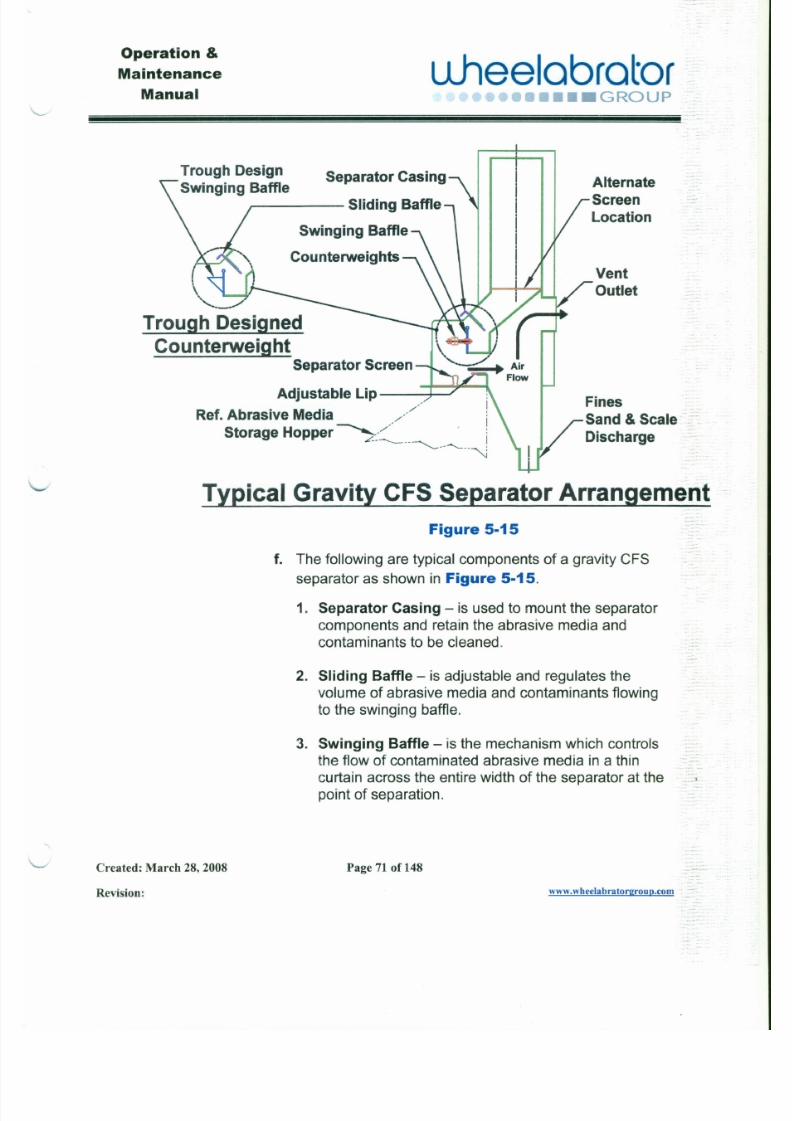
7/30/2019 MANUAL DE USUARIO GRANALLADORA (2).pdf
http://slidepdf.com/reader/full/manual-de-usuario-granalladora-2pdf 86/240
Trough Design Separator CasingSwinging Baffle Alternate
Screen
LocationJ Sliding Baffle
Swinging Baffle
Cou nterweightsVent
Outlet" -Trough Desi~
Counterwei9!!!Separator Screen
Adjustable Lip -}3~
Ref. Abrasive Media /Storage Hopper ~:~__ I~ - - - - - - - - ~
Fines
Sand &Scale' ---Discharge
IYPical Gravity CFS Separator Arrangement
Figure 5·15
- _ .. Operation &
uheelobrotoraintenance
Manual n·••••••••• GROUP
. ... .:»
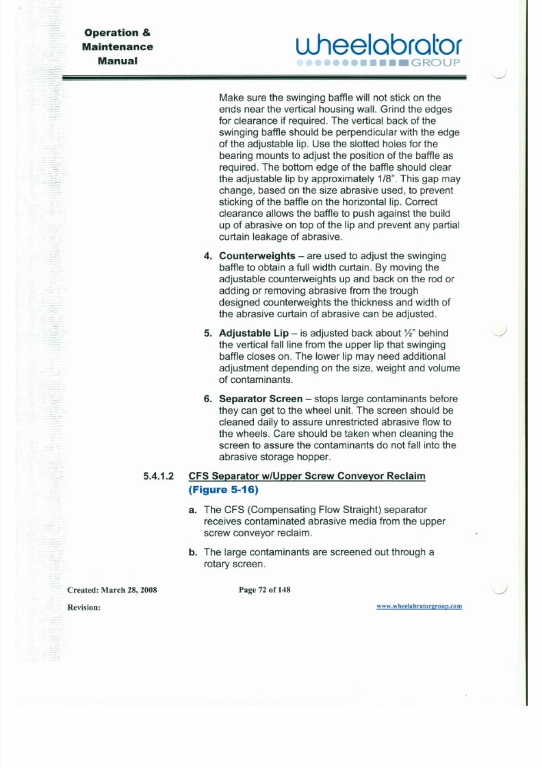
7/30/2019 MANUAL DE USUARIO GRANALLADORA (2).pdf
http://slidepdf.com/reader/full/manual-de-usuario-granalladora-2pdf 87/240
.. Make sure the swinging baffle will not stick on the..
- _ . ends near the vertical housing wall. Grind the edgesfor clearance if required. The vertical back of theswinging baffle should be perpendicular with the edgeof the adjustable lip. Use the slotted holes for the
bearing mounts to adjust the position of the baffle asrequired. The bottom edge of the baffle should clear
.. the adjustable lip by approximately 1/8". This gap may.'. ..
change, based on the size abrasive used, to prevent
sticking of the baffle on the horizontal lip. Correctclearance allows the baffle to push against the build
up of abrasive on top of the lip and prevent any partial
curtain leakage of abrasive.
4. Counterweights - are used to adjust the swingingbaffle to obtain a full width curtain. By moving the
adjustable counterweights up and back on the rod or
adding or removing abrasive from the troughdesigned counterweights the thickness and width ofthe abrasive curtain of abrasive can be adjusted .
.J. Adjustable Lip - is adjusted back about %" behind
-,-",. the vertical fall line from the upper lip that swinging
baffle closes on. The lower lip may need additional
adjustment depending on the size, weight and volume
Operation &
Maintenance
Manual
u.heelabrator .-~••••• GROUP
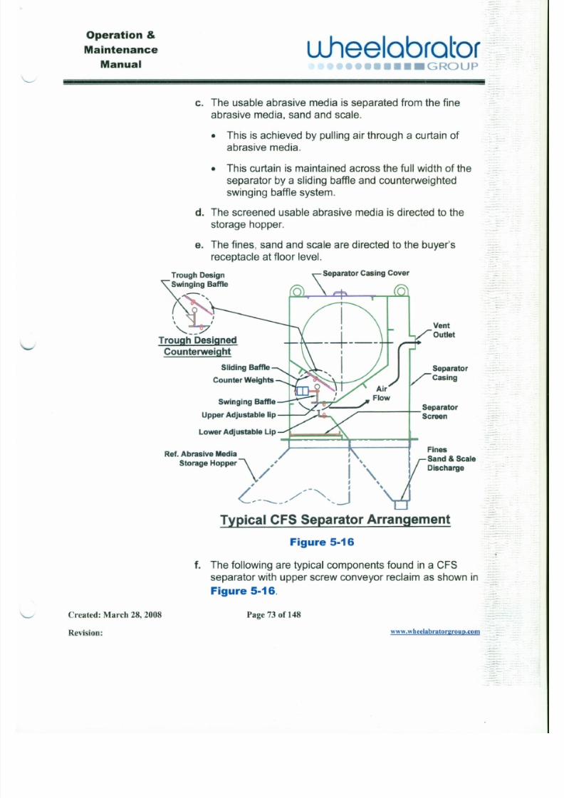
7/30/2019 MANUAL DE USUARIO GRANALLADORA (2).pdf
http://slidepdf.com/reader/full/manual-de-usuario-granalladora-2pdf 88/240
c. The usable abrasive media is separated from the fine
abrasive media, sand and scale.
• This is achieved by pulling air through a curtain of
abrasive media.
• This curtain is maintained across the full width of theseparator by a sliding baffle and counterweightedswinging baffle system.
d. The screened usable abrasive media is directed to the
storage hopper.
e. The fines, sand and scale are directed to the buyer'sreceptacle at floor level.
Trough Design
Swinging Baffle
Separator Casing Cover
~
' - - - -Trough DesignedCounterweight
Vent
Outlet
Separator
Casing
Operation &
Maintenance
Manual
u .hee lab ra to r•••• C•••• GROUP
.:»
7/30/2019 MANUAL DE USUARIO GRANALLADORA (2).pdf
http://slidepdf.com/reader/full/manual-de-usuario-granalladora-2pdf 89/240
1. Separator Casing - is used to mount the separator
components and retain the abrasive media andcontaminants to be cleaned.
2. Separator Casing Cover - is for access to the upperscrew conveyor and rotary screen.
Warning: DO NOT remove separator casing
cover with power on the equipment
or with the screw conveyor or
screen running.
3. Sliding Baff le - is adjustable and regulates thevolume of abrasive media and contaminants flowingto the swinging baffle.
4. Swinging Baff le - is the mechanism which controls
the flow of contaminated abrasive media in a thincurtain across the entire width of the separator at thepoint of separation.
Make sure the swinging baffle will not stick on the
ends near the vertical housing wall. Grind the edges
for clearance if required. The vertical back of the
swinging baffle should be perpendicular with the edge
J
Operation &
Maintenance
Manual
u.heelobrotor -~~•••• GROUP
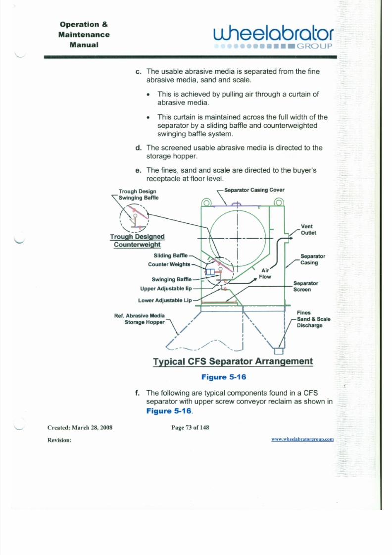
7/30/2019 MANUAL DE USUARIO GRANALLADORA (2).pdf
http://slidepdf.com/reader/full/manual-de-usuario-granalladora-2pdf 90/240
C. The usable abrasive media is separated from the fine
abrasive media, sand and scale.
• This is achieved by pulling air through a curtain of
abrasive media.
• This curtain is maintained across the full width of theseparator by a sliding baffle and counterweightedswinging baffle system.
d. The screened usable abrasive media is directed to the
storage hopper.
e. The fines, sand and scale are directed to the buyer's
receptacle at floor level.
Trough Design
Swinging Baffle
Separator Casing Cover
~,- -Trough Designed
Counterweight
Vent
Outlet
Separator
Casing
Operation&
Maintenance
ManualLLheelabrator - : ~ ; f s :. .
••••• GROUP ...- -' - . . . . . -
7/30/2019 MANUAL DE USUARIO GRANALLADORA (2).pdf
http://slidepdf.com/reader/full/manual-de-usuario-granalladora-2pdf 91/240
.. ::'::;;::"'.-6. Upper Adjustable Lip - is adjusted to keep the back
face of the swinging baffle vertical and parallel withthe air opening behind the abrasive media curtain.
7. Lower Adjustable Lip - is adjusted back about %"
behind the vertical fall line from the upper lip that
swinging baffle closes on. The lower lip may need
additional adjustment depending on the size, weightand volume of contaminants.
8. Separator Screen - stops large contaminants before
they can get to the wheel unit. The screen should be
cleaned daily to assure unrestricted abrasive flow to
the wheels. Care should be taken when cleaning the
screen to assure the contaminants do not fall into theabrasive storage hopper.
5.4.1.3 LP Magnetic Separators
The LP (Low Profile) series of magnetic separators provide asignificant improvement in operating efficiency and costreduction for blast cleaning equipment in a typical foundry.
Using a two (2) stage approach, the LP units remove coarse
:~~·-'.::0~:...
.- .
-
- - Operation &
L lhee lab ra to r,
- -Maintenance
Manual ,'ro.,..... •..•.,... r . . . - . , . • • • GROUP
•.. .- .. --...J
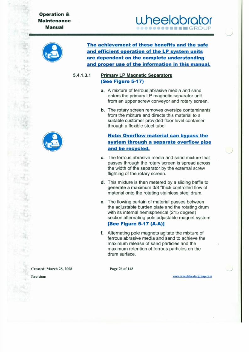
7/30/2019 MANUAL DE USUARIO GRANALLADORA (2).pdf
http://slidepdf.com/reader/full/manual-de-usuario-granalladora-2pdf 92/240
---." .-c__ =The achievement of these benefits and the safe
and efficient operation of the LP system units
are dependent on the complete understanding
and ~er use of the information in this manual.
5.4.1.3.1 Primary LP Magnet ic Separators
-(See Figure 5-17)
-
a. A mixture of ferrous abrasive media and sandenters the primary LP magnetic separator unit
from an upper screw conveyor and rotary screen.
b. The rotary screen removes oversize contaminants- -_ . . . . . .
from the mixture and directs this material to a. suitable customer provided floor level container
~ through a flexible steel tube.
C )Note: Overflow material can bypass the
system through a separate overflow pipe
and be recycled.J
c. The ferrous abrasive media and sand mixture that
passes through the rotary screen is spread acrossthe width of the separator by the external screw
Operation &
Maintenance
Manualuheelabrator .~.
.C'••• GROUP' - - . . . -
!i!!!i!!!!!i!!!!i!!!i!!!!!i!!!!i!!!i!!!!!i!!!!i!!!i!!!!!i!!!!i!!!i!!!!!i!!!!i!!!i!!!!!i!!!!i!!!i!!!!!i!!!!i!!!i!!!!!i!!!!i!!!i!!!!!i!!!!i!!!i!!!!!i!!!!i!!!i!!!!!i!!!!i!!!i!!!!!i!!!!i!!!i!!!!!i!!!!i!!!i!!!!!i!!!!i!!!i!!!!!i!!!!i!!!i!!!!!i!!!!i!!!i!!!!!i!!!~~~~~~.-'
7/30/2019 MANUAL DE USUARIO GRANALLADORA (2).pdf
http://slidepdf.com/reader/full/manual-de-usuario-granalladora-2pdf 93/240
6. Upper Adjustable Lip - is adjusted to keep the back
face of the swinging baffle vertical and parallel withthe air opening behind the abrasive media curtain.
7. Lower Adjustable Lip - is adjusted back about %"behind the vertical fall line from the upper lip that
swinging baffle closes on. The lower lip may needadditional adjustment depending on the size, weight
and volume of contaminants.
.-
~~
8. Separator Screen - stops large contaminants beforethey can get to the wheel unit. The screen should be
cleaned daily to assure unrestricted abrasive flow to
the wheels. Care should be taken when cleaning thescreen to assure the contaminants do not fall into theabrasive storage hopper.
5.4.1.3 LP Magnetic Separators
The LP (Low Profile) series of magnetic separators provide asignificant improvement in operating efficiency and costreduction for blast cleaning equipment in a typical foundry.
Using a two (2) stage approach, the LP units remove coarse
Operation &
Maintenance
Manual
u .hee lab ra to r .••••••.... r-"\0"'" ••• G RO U P
'•.
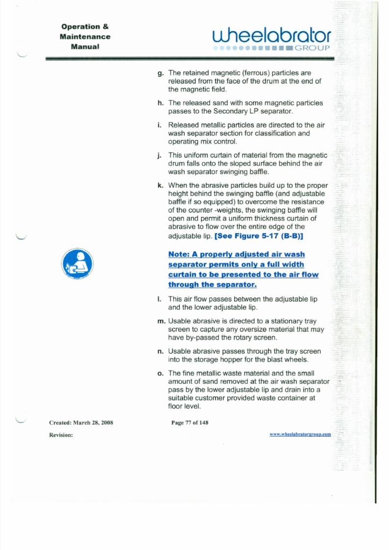
7/30/2019 MANUAL DE USUARIO GRANALLADORA (2).pdf
http://slidepdf.com/reader/full/manual-de-usuario-granalladora-2pdf 94/240
. '.
g. The retained magnetic (ferrous) particles are
released from the face of the drum at the end ofthe magnetic field.
h. The released sand with some magnetic particles
passes to the Secondary LP separator.
i. Released metallic particles are directed to the airwash separator section for classification and
operating mix control.
j. This uniform curtain of material from the magneticdrum falls onto the sloped surface behind the air
wash separator swinging baffle.
k. When the abrasive particles build up to the proper
height behind the swinging baffle (and adjustablebaffle if so equipped) to overcome the resistance
of the counter -weights, the swinging baffle willopen and permit a uniform thickness curtain ofabrasive to flow over the entire edge of the
adjustable lip. [See Figure 5-17 (8-8)]
Note: A properly adjusted air wash
. '1 . . , -,.-
Operation &
Maintenance
Manual
uheelabrator :'~•••• GROUP
'- - '" .
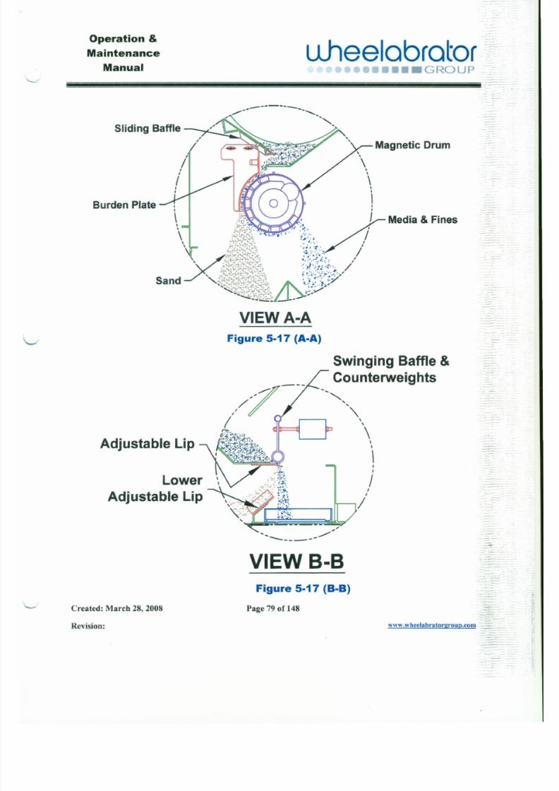
7/30/2019 MANUAL DE USUARIO GRANALLADORA (2).pdf
http://slidepdf.com/reader/full/manual-de-usuario-granalladora-2pdf 95/240
Sliding Baffle
--------",-- --~-- " " -
Burden Plate
Magnetic Drum,
\,,\,
iI
\ ~ )~~~ / Media &Fines
\~,\\~' ''''ir~~~b//Sand '--.: '-'._,~M'~~,' I 1 \ . . . • . . . . . . .> '
-~~i~1~~LJ._~~:~
VIEW A-AFigure 5-17 (A-A)
Swinging Baffle &
Counterweights
-
-: :
Operation &
Maintenance
Manualu.heelabrator
••• GROUP
- - ~~~~~~~~~~~~~~~~~~~~~ J
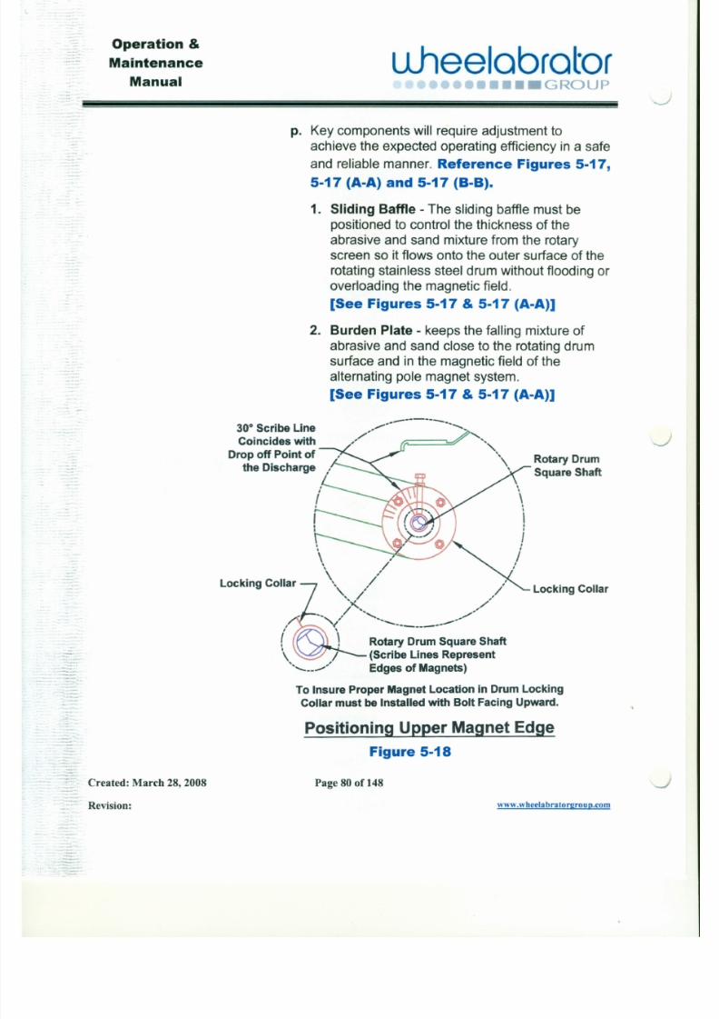
7/30/2019 MANUAL DE USUARIO GRANALLADORA (2).pdf
http://slidepdf.com/reader/full/manual-de-usuario-granalladora-2pdf 96/240
p. Key components will require adjustment to
achieve the expected operating efficiency in a safeand reliable manner. Reference Figures 5-17,
5-17 (A-A) and 5-17 (B-B).
1. Sliding Baffle - The sliding baffle must bepositioned to control the thickness of the
abrasive and sand mixture from the rotaryscreen so it flows onto the outer surface of the
rotating stainless steel drum without flooding oroverloading the magnetic field.
[See Figures 5-17 & 5-17 (A-A)]
2. Burden Plate - keeps the falling mixture ofabrasive and sand close to the rotating drumsurface and in the magnetic field of the
alternating pole magnet system.
[See Figures 5-17 &5-17 (A-A)]
30° Scribe Line
Coincides with
Drop off Point of
the Discharge
- - - - - - - - -, - - - ~~-~'
"
Rotary Drum
Square Shaft
J
.. . . ;;;-.
Operation &
Maintenance
ManualuJ 1eelabrator~
••••• GROUP .::-::~:-
7/30/2019 MANUAL DE USUARIO GRANALLADORA (2).pdf
http://slidepdf.com/reader/full/manual-de-usuario-granalladora-2pdf 97/240
3. Alternating Pole Magnetic Drum - The
magnetic drum system requires properpositioning of the fixed alternating pole magnet
inside the rotating stainless steel drum (Refer
to Figure 5-17). Using an adjustable wrench __
on the square end shaft, align the upper end of '::L
the scribe mark on the end of the shaft with thelonger scribe mark on the face of the locking
collar. Record the short scribe mark referencepoint from the locking collar. This will position
the upper magnet edge with the drop off point
of the discharge. The initial setting may needfurther adjustment to use the magnetic field tominimize the impact of the falling abrasive andsand on the drum surface and maintain a good
discharge arc for the metallic particles under
the drum.[See Figures 5-17, 5-17 (A-A) and 5-18] 'C-
4. Swinging Baffle &Counterweights -The
swinging baffle should swing freely but remainclosed until sufficient abrasive material builds
up behind the baffle to insure the flow of a full
- - - " ~~.
Operation &
Maintenance
Manualuheelobrotor
•••• GROUP
- -.J
7/30/2019 MANUAL DE USUARIO GRANALLADORA (2).pdf
http://slidepdf.com/reader/full/manual-de-usuario-granalladora-2pdf 98/240
. . ': ,"
Correct clearance allows the baffle to push
against the build up of abrasive on top of the lipand prevent any partial curtain leakage ofabrasive.
[See Figures 5-17 and 5-17 (8-8)]
5. Adjustab le Lip - can be adjusted along withthe swinging baffle adjustment to achieve theposition and relationships described in
paragraph 4 above.[See Figures 5-17 and 5-17 (8-8)]
6. Lower Adjustable Lip - Establish a minimum
gap of %' between the top front edge of this lip
and the back edge of the falling abrasive mix.
Additional adjustments of this lip may berequired in conjunction with adjustments in air
flow through the separator and size, weight &volume of contaminants. An air gap isnecessary to allow some horizontal movementof usable abrasive particles as the horizontalair stream carries the lighter weight
contaminants and unusable metallic fines out
of the abrasive mix.
J
Operation &
Maintenance
Manual~
Llheelabrator ~~~•••• GROUP ': :~t
!!! ii !!!!!!!!i i!!!i i!!!!!!!!i i!!!i i!!!!!!!!i i!!! i i!!!!!!!!ii !!! ii!!!!!!!!ii!!!ii!!!!!!!!ii!!!ii!!!!!!!!ii!!!ii!!!!!!!!ii!!!ii!!!!!!!!ii!!!ii!!!!!!!!ii!!!ii!!!!!!!!ii!!!ii!!!!!!!!ii!!!ii!!!!!!!!ii!!!ii!!!!!!!!ii!!!ii!!!!!!!! i i!!!i i!!!!!!!!ii!!!i i!!!!!!!!i i!!!ii!!!!!!!! ii! !!ii !!!!!!!! ii !!!i i!!!!!!!!ii!!!ii!!!!!!!!ii!!!ii!!!!!!!!iii!!!!!!!!!!! ! .. - - - .
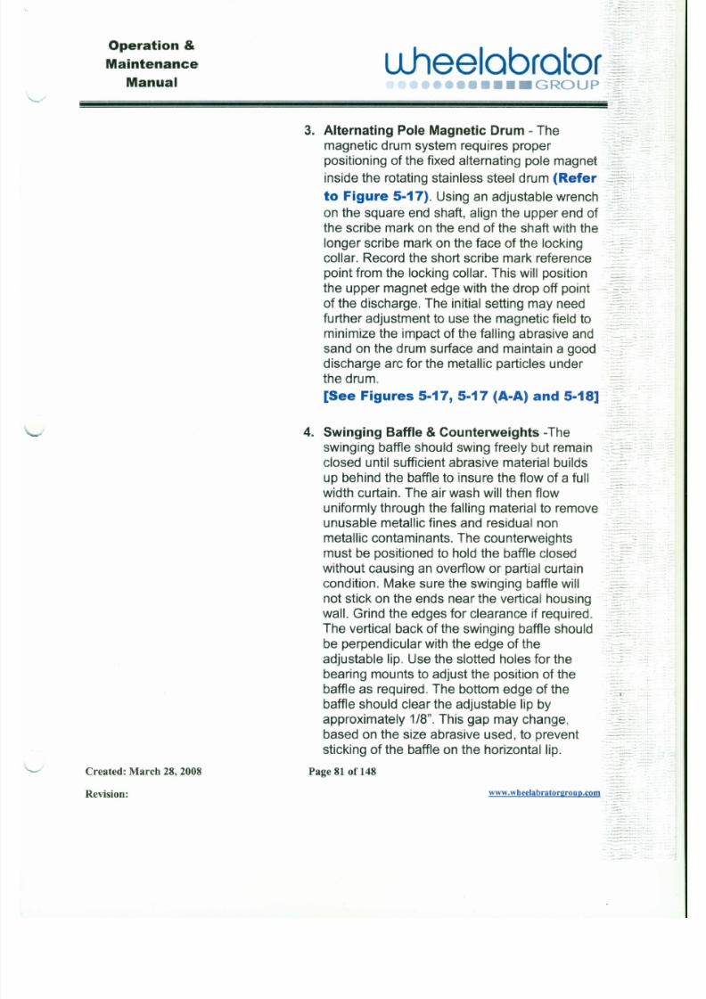
7/30/2019 MANUAL DE USUARIO GRANALLADORA (2).pdf
http://slidepdf.com/reader/full/manual-de-usuario-granalladora-2pdf 99/240
3. Alternating Pole Magnetic Drum - The
magnetic drum system requires properpositioning of the fixed alternating pole magnet
inside the rotating stainless steel drum (Refer
to Figure 5-17).Using an adjustable wrench~,:-;
on the square end shaft, align the upper end of ...:-:..
the scribe mark on the end of the shaft with the
longer scribe mark on the face of the locking
collar. Record the short scribe mark referencepoint from the locking collar. This will position
the upper magnet edge with the drop off point
of the discharge. The initial setting may needfurther adjustment to use the magnetic field tominimize the impact of the falling abrasive andsand on the drum surface and maintain a good
discharge arc for the metallic particles under
the drum.[See Figures 5-17, 5-17(A-A) and 5-18]
4. Swinging Baffle &Counterweights -The
swinging baffle should swing freely but remainclosed until sufficient abrasive material builds
up behind the baffle to insure the flow of a full
..~=-
-
::;".~-'
-. . . . • .-
:
Operation &
u.heelabrator;~aintenance
Manual ":)•••••••• GROUP
" -
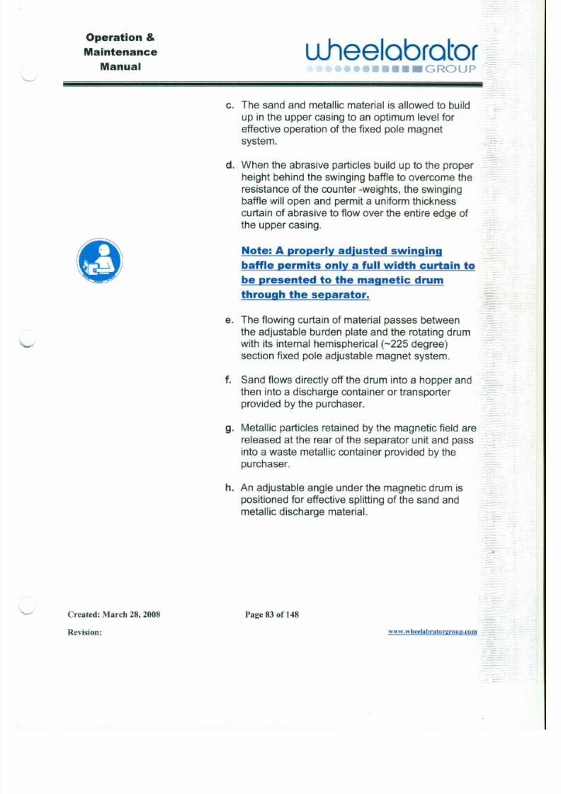
7/30/2019 MANUAL DE USUARIO GRANALLADORA (2).pdf
http://slidepdf.com/reader/full/manual-de-usuario-granalladora-2pdf 100/240
.. . - 'c. The sand and metallic material is allowed to build
up in the upper casing to an optimum level foreffective operation of the fixed pole magnet ,~...
-
system..-
d. When the abrasive particles build up to the proper .•.-
height behind the swinging baffle to overcome the
resistance of the counter -weights, the swingingbaffle will open and permit a uniform thickness
curtain of abrasive to flow over the entire edge ofthe upper casing.
0-
Note: A properly adjusted swinging_"H_
baffle permits only a full width curtain to
be presented to the magnetic drum
through the separator.::...z;
""~;i,:',:' ::~;:~~
e. The flowing curtain of material passes between
the adjustable burden plate and the rotating drum-"
with its internal hemispherical (-225 degree)
section fixed pole adjustable magnet system.. •. . . .
f. Sand flows directly off the drum into a hopper and
. - .. - -: : : : . ;~. = . ~ : . ' "
Operation &
Maintenance
Manualuheelabrator
••••••••• GROUP
;. ::~::~l!!!!.~~~~~~~~~~~~~~~~~~~~~~..:: .•:~*.~ .: ~==.:.."- .:- . : : : . : : : : : : : .. :~
,J
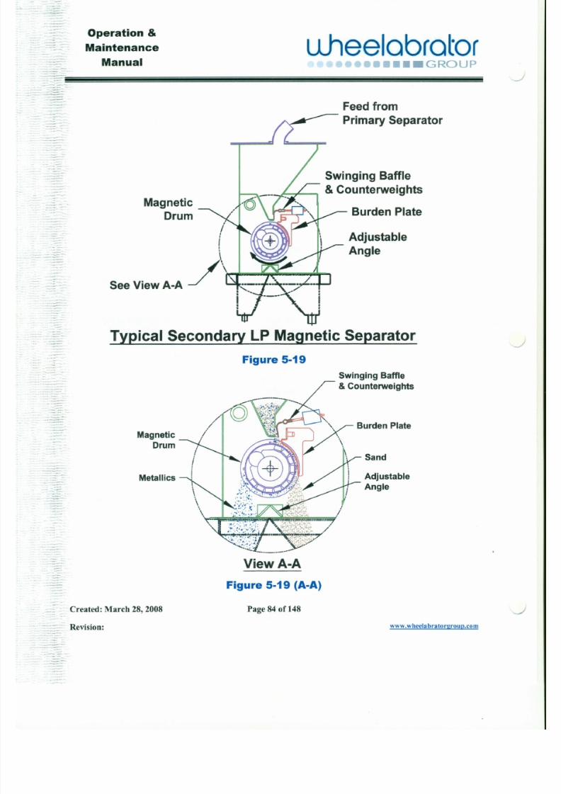
7/30/2019 MANUAL DE USUARIO GRANALLADORA (2).pdf
http://slidepdf.com/reader/full/manual-de-usuario-granalladora-2pdf 101/240
. - . . . : :. : . . ::
--.- . . . . .
~~. - . :: :=~:.
- ~.. - :: : " ~' : :::
- , _ .. . .. •
Feedfrom
Primary Separator
Magnetic
Drum
Adjustable
Angle
Swinging Baffle
• I , I & Counterweights7 j1 .,, "
Burden Plate
ii
/\ ,
SeeViewA-A .':::::'-"":~"-:-;.~"";
,
~.---- I• •• •
TYPical Secondary LP Magnetic Separator
Figure 5-19
Swinging Baffle
J
Operation &
Maintenance
Manual
L lhee lab ra to r•••• GROUP -
, , - - - . -,-.~..~-.
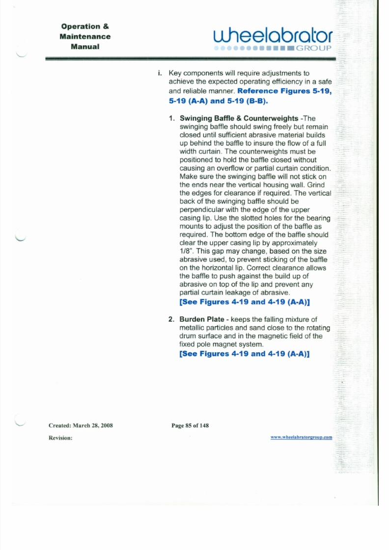
7/30/2019 MANUAL DE USUARIO GRANALLADORA (2).pdf
http://slidepdf.com/reader/full/manual-de-usuario-granalladora-2pdf 102/240
i. Key components will require adjustments to
achieve the expected operating efficiency in a safeand reliable manner. Reference Figures 5-19,
5-19 (A-A) and 5-19 (B-B).
1. Swinging Baffle & Counterweights -Theswinging baffle should swing freely but remainclosed until sufficient abrasive material builds
up behind the baffle to insure the flow of a fullwidth curtain. The counterweights must be
positioned to hold the baffle closed without
causing an overflow or partial curtain condition.
Make sure the swinging baffle will not stick onthe ends near the vertical housing wall. Grind
the edges for clearance if required. The verticalback of the swinging baffle should be
perpendicular with the edge of the uppercasing lip. Use the slotted holes for the bearingmounts to adjust the position of the baffle as
required. The bottom edge of the baffle shouldclear the upper casing lip by approximately1/8". This gap may change, based on the size
abrasive used, to prevent sticking of the baffle
Operation &
Maintenance
Manualuheelabrator
••• GROUP
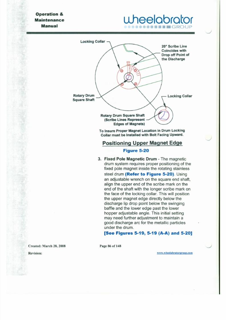
7/30/2019 MANUAL DE USUARIO GRANALLADORA (2).pdf
http://slidepdf.com/reader/full/manual-de-usuario-granalladora-2pdf 103/240
::
Locking Collar
20° Scribe LineCoincides withDrop off Point ofthe Discharge
Rotary DrumSquare Shaft
Locking Collar
Rotary Drum Square Shaft(Scribe Lines Represent
Edges of Magnets)
To Insure Proper Magnet Location in Drum LockingCollar must be Installed with Bolt Facing Upward.
PositioningU~er MagnetEdge
Figure 5-20
Operation &
Maintenance
Manual
L lhee lab ra to r•••• GROUP
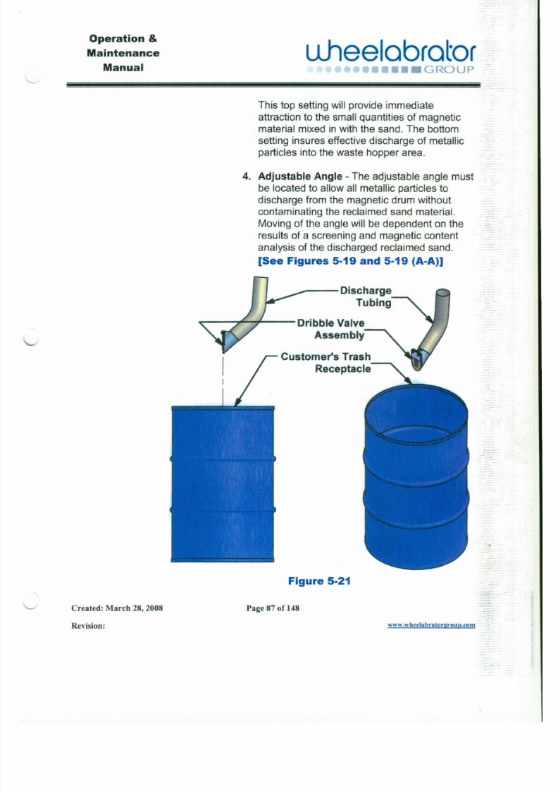
7/30/2019 MANUAL DE USUARIO GRANALLADORA (2).pdf
http://slidepdf.com/reader/full/manual-de-usuario-granalladora-2pdf 104/240
This top setting will provide immediate
attraction to the small quantities of magneticmaterial mixed inwith the sand. The bottomsetting insures effective discharge of metallicparticles into the waste hopper area.
4. Adjustable Angle - The adjustable angle mustbe located to allow all metallic particles todischarge from the magnetic drum without
contaminating the reclaimed sand material.Moving of the angle will be dependent on theresults of a screening and magnetic content
analysis of the discharged reclaimed sand.
[See Figures 5-19 and 5-19 (A-A)]
c: ,r sf Dribble Valve
Assembly·
Customer's TrashReceptacle
-
' - . . . . -
Operation &
Maintenance
Manual
uJ lee lab ra to r•••••••• GROUP
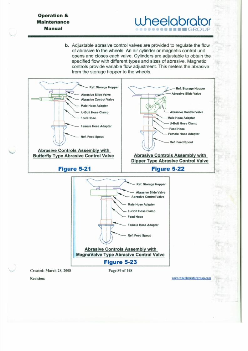
7/30/2019 MANUAL DE USUARIO GRANALLADORA (2).pdf
http://slidepdf.com/reader/full/manual-de-usuario-granalladora-2pdf 105/240
b. Adjustable abrasive control valves are provided to regulate the flow
of abrasive to the wheels. An air cylinder or magnetic control unitopens and closes each valve. Cylinders are adjustable to obtain thespecified flow with different types and sizes of abrasive. Magneticcontrols provide variable flow adjustment. This meters the abrasive
from the storage hopper to the wheels.
Abras ive Cont ro ls Assembly with
Butterfly Type Abrasive Control Valve
« - - . . . . . . - - - - ~ - - - - ~- . ' . I ' - : : J / - - - - Ref. Storage Hopper
Fl ' ~ Abrasive Slide Valve
Abrasive Control Valve
MaleHoseAdapter
U-8olt Hose Clamp
FeedHose
Female HoseAdapteri V
j I ') , j ~ Ref. FeedSpout
l,\J ))'-+
Ref. Storage Hopper
~ ! L -=;:t--- Abrasive Slide Valve
Abrasive Control Valve
U-8olt Hose Clamp
FeedHose
Female Hose Adapter
Abras ive Cont ro ls Assembly with
Dipper Type Abras ive Cont ro l Valve
Operation &
uheelabratoraintenance
Manual " ,... ro. ,.,. ,... ••..••••••• G RO U P
_ .r "~J
7/30/2019 MANUAL DE USUARIO GRANALLADORA (2).pdf
http://slidepdf.com/reader/full/manual-de-usuario-granalladora-2pdf 106/240
c. The following are common components of a typical abrasivecontrols assembly as shown in Figures 5-21 , 5-22 and 5-23.
1. Abrasive Slide Valve - This is a manually operated slide valve
to open or close the media flow from the storage hopper to theblast wheel. This valve makes it possible to close off the flow of
media to perform repairs and maintenance on the abrasivecontrols system with have to drain the storage hopper.
Do not use slide valve to meter abrasive
-- I - , media flow.. '_ .
2. Abrasive Control Valve - This meters the abrasive from thestorage hopper to the wheels. There are three (3) types of
abrasive control valves.
[See Figures 5-21, 5-22 and 5-23]
.:. Butterfly Type - An air cylinder opens and closes a wafer
type paddle valve. The cylinder is adjustable to obtain thespecified flow with different types and sizes of abrasive. '-...J
.:. Dipper Type - An air cylinder opens and closes a totally
enclosed dipper cup type valve. An adjustable stop, with
Operation &
Maintenance
Manual
~
uheeloorotor..~•••• GROUP::;~
~~~~~~~~~~~~~~~~~~~~~: ....-
7/30/2019 MANUAL DE USUARIO GRANALLADORA (2).pdf
http://slidepdf.com/reader/full/manual-de-usuario-granalladora-2pdf 107/240
5. Feed Hose - This conveys the abrasive media from the
abrasive control valve to the blast wheel. There are two (2)
types of feed lines .
•:. Abrasive Resistant Rubber Hose - This consists of
abrasive resistant rubber hose and is the most common feedline type. It is flexible and easy to install.
.:. Hard Piping - This consists of a network of hard pipe and
weld elbows to feed the wheels.
-"" . -'- ~ :: - ~ . .. :
6. Female Hose Adapter - This is used to attach rubber hose typefeed lines to the feed spout of the blast wheel.
Operation &
Maintenance
Manual
I Ineelobrotor :~~~J I ----.,--...~,•••• GROUP:~~::::c;- .
~
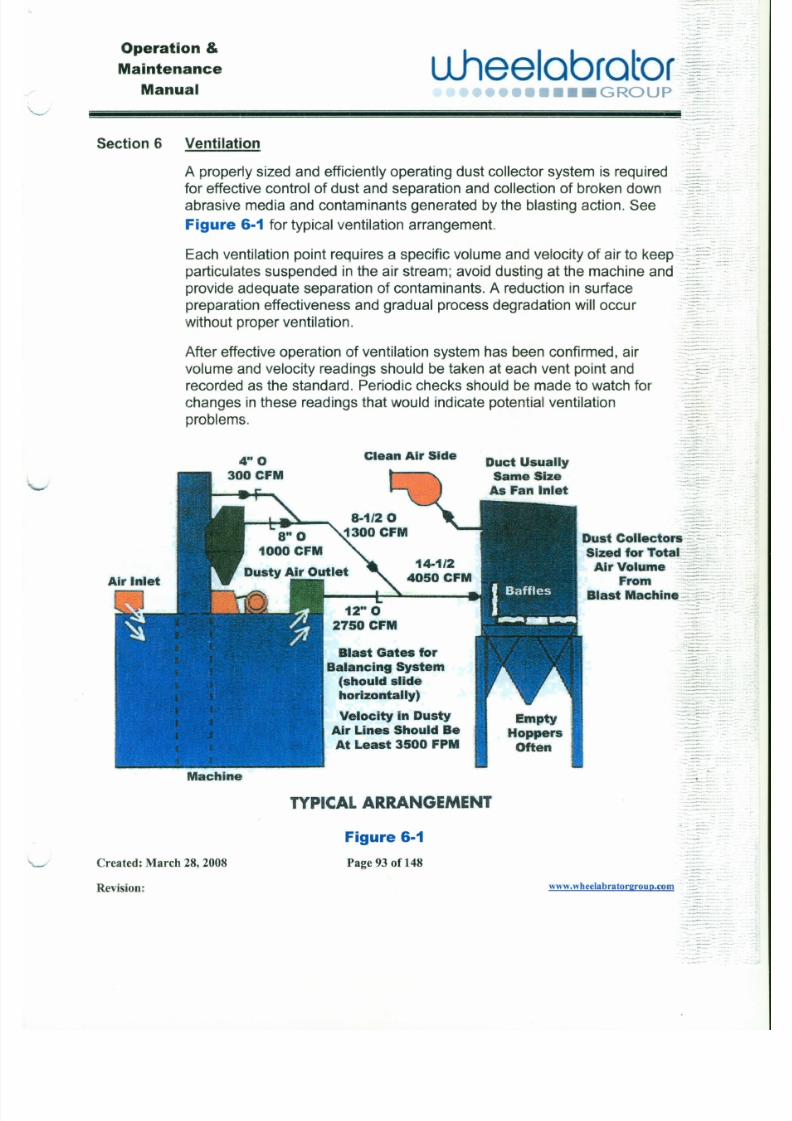
7/30/2019 MANUAL DE USUARIO GRANALLADORA (2).pdf
http://slidepdf.com/reader/full/manual-de-usuario-granalladora-2pdf 108/240
Section 6 Ventilation
A properly sized and efficiently operating dust collector system is requiredfor effective control of dust and separation and collection of broken downabrasive media and contaminants generated by the blasting action. See
Figure 6·1 for typical ventilation arrangement.
Each ventilation point requires a specific volume and velocity of air to keep.~;.:¥:::;:.~:.:~
particulates suspended in the air stream; avoid dusting at the machine and "--
provide adequate separation of contaminants. A reduction in surface ..=:-"-preparation effectiveness and gradual process degradation will occur .:~~.
without proper ventilation. _ ..
After effective operation of ventilation system has been confirmed, airvolume and velocity readings should be taken at each vent point and
recorded as the standard. Periodic checks should be made to watch forchanges in these readings that would indicate potential ventilation
problems.
~. - ,,- - .:: ,. ,=: - : :
Clean Air SideDuct Usually
Same Size
As Fan Inlet
Dust Collectors :: := ':: ;;:-~. - ;.
Operation & I Ih I b tMaintenance UJ lee a ra ·o r
~::=:~. Manual ., r,....,- . " .- . ,. .., ,.. ., •• • G RO U P
. jt i~=~~~~··~ -~~~~~~~~~~~~~~~ .:»
7/30/2019 MANUAL DE USUARIO GRANALLADORA (2).pdf
http://slidepdf.com/reader/full/manual-de-usuario-granalladora-2pdf 109/240
6.1 Dust Collectors
Dust collectors provide three very important functions related to theclean and efficient operation of a blast cleaning machine.
1. The dust collector exhaust fan maintains a steady air flow throughthe separator, required for the air wash operation. The air flow pulls
dust, fines and other contaminants from the thin curtain of abrasive
media that falls over the lip of the separator. Operating properly, adust collector will take out only unusable fines.
-"--"2. The dust collector exhauster provides a negative pressure in the
blast cabinet. This is needed to keep dust from puffing out of the
blast machine. The puffing effect is caused by the air pump actionfrom blast wheel units ...-
By creating a negative pressure and controlling the flow of air to thedust collector, air outside the cabinet is dawn into the cabinet,rather than air and dust inside the cabinet being forced out.
-/
~
- . . .. -...--.. ~"
:~~~; .uheelobrotor~f:
••••• GROUP::~~?: .,..:~~'.~=:
~~~~~~~~~~~~~~~~~~~~~~!!!!!!!l!!!: •.=~:. ::_:: '
Operation &
Maintenance
Manual
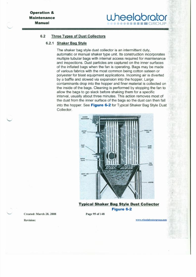
7/30/2019 MANUAL DE USUARIO GRANALLADORA (2).pdf
http://slidepdf.com/reader/full/manual-de-usuario-granalladora-2pdf 110/240
SH A K ER
M EC H A NISM
ClEAN AIR
SIDE
. . . . • .:".
6.2 ThreeTypesof DustCollectors
6.2.1 ShakerBagStyle - : : J g ~ =The shaker bag style dust collector is an intermittent duty, ~~~~::.".:automatic or manual shaker type unit. Its construction incorporates:j¥~;:":'-~;
multiple tubular bags with internal access required for maintenance __ .
and inspections. Dust particles are captured on the inner surfaces ::=~~:~of the inflated bags when the fan is operating. Bags may be made : =:
of various fabrics with the most common being cotton sateen or
polyester for blast equipment applications. Incoming air is diverted ~=:::
by a baffle and slowed via expansion into the hopper. Large ~ : f ; : : = ' - : :contaminants drop into the hopper and finer material is collected on.::~~··"f~:
the inside of the bags. Cleaning is performed by stopping the fan to .._ ..allow the bags to go slack before shaking them for a specificinterval, usually about three minutes. This action removes most of _..:::::::-:,.:
the dust from the inner surface of the bags so the dust can then fall ' L ~ ~ '~:into the hopper. See Figure 6-2for Typical Shaker Bag Style Dust ':::--'~:. :~Collector. : : : : . - = : : : : ' ~ -
--'''.
- : ~ ~ ' ~ - * ~ ~ ~ : : ' ~, . - .. ".--,-~.~ .,
.. , .. ,-_ . ._-,..". - . - - .. .~ . .'-.
Operation &
Maintenance
Manual
L lhee lab ra to r• ••• GROUP
. .-.
.•.__ .~~~~~~~~~~~~~~~~~~~~!!i!i!ll!i!i!
6.2.1.1 Elements of a Typical Shaker Bag Style Dust Collector:
J
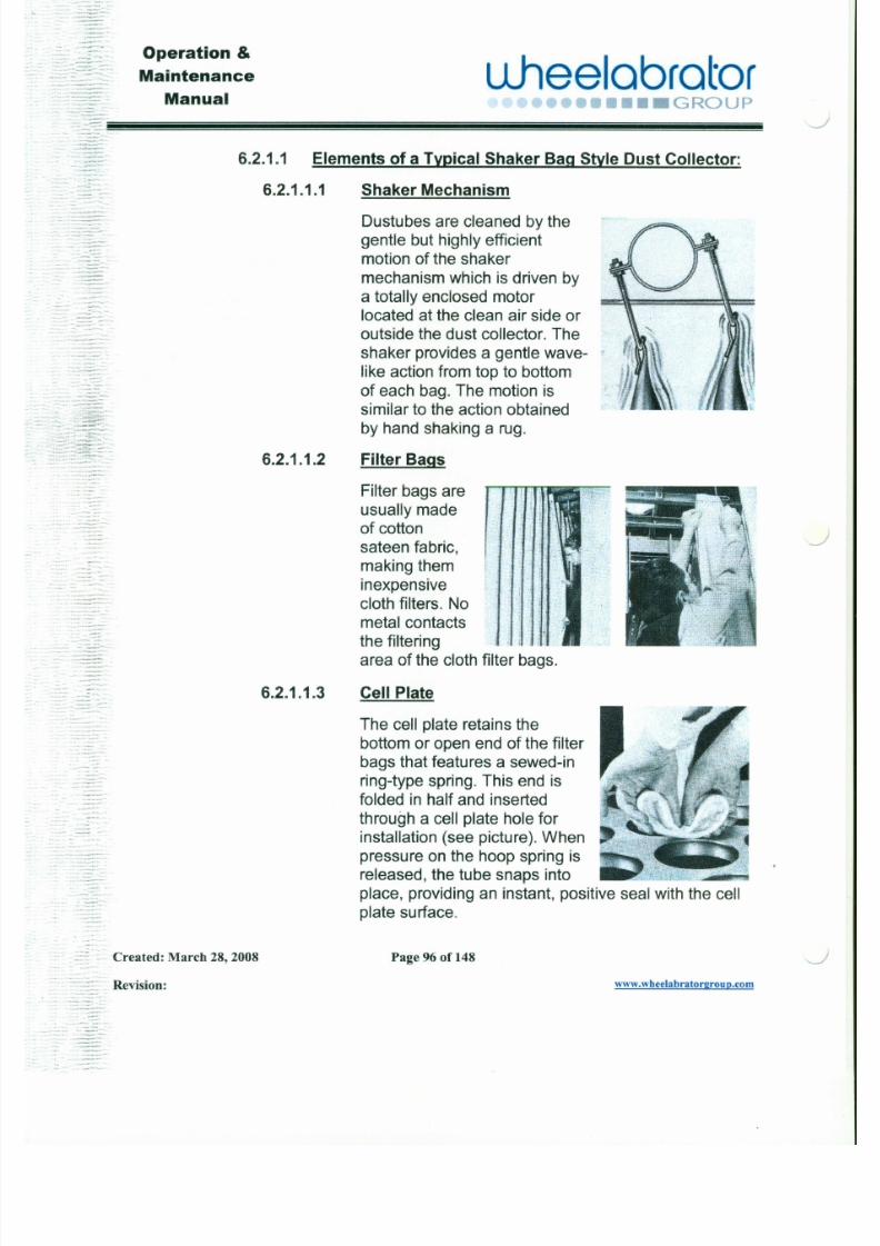
7/30/2019 MANUAL DE USUARIO GRANALLADORA (2).pdf
http://slidepdf.com/reader/full/manual-de-usuario-granalladora-2pdf 111/240
. - - '" : :: =. "~ :.
'-" . . . .--~.- '. • _ . _ - " .
: : . : - : - . = - ~ -.
: '- ~ ~ ~ ~ - ' : l "
: : : : : = : " - = : ~ X ":~:;:::.~.~ . . ,,- .
: : ~ : : l ~ : -= : ~ ~ : : · :.,-- . . • .~ . . •- '.
_~:7'::.::.~~~~:.-
- -
6.2.1.1.1
6.2.1.1.2
Shaker Mechanism
Dustubes are cleaned by the
gentle but highly efficientmotion of the shaker
mechanism which is driven by
a totally enclosed motorlocated at the clean air side or
outside the dust collector. Theshaker provides a gentle wave-
like action from top to bottom
of each bag. The motion issimilar to the action obtainedby hand shaking a rug.
Filter Bags
Filter bags areusually madeof cottonsateen fabric,making them
inexpensive
~
Operation &
Maintenance
Manual\ . . . . . . . . -
LLhee labra tor••••• GROUP
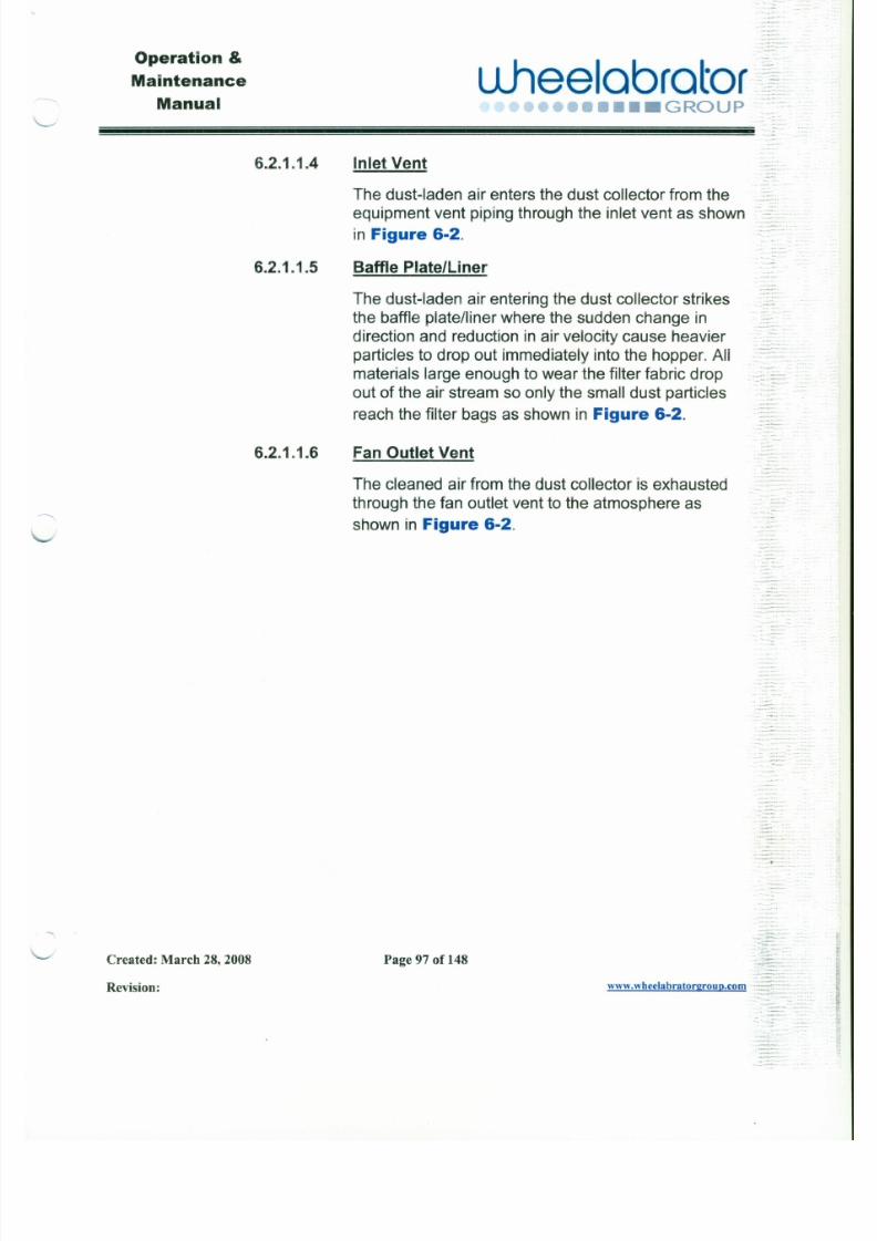
7/30/2019 MANUAL DE USUARIO GRANALLADORA (2).pdf
http://slidepdf.com/reader/full/manual-de-usuario-granalladora-2pdf 112/240
- - - - - -
6.2.1.1.4
6.2.1.1.5
6.2.1.1.6
Inlet Vent
The dust-laden air enters the dust collector from theequipment vent piping through the inlet vent as shown
in Figure 6-2.
Baffle Plate/Liner
The dust-laden air entering the dust collector strikesthe baffle platelliner where the sudden change in
direction and reduction in air velocity cause heavierparticles to drop out immediately into the hopper. All
materials large enough to wear the filter fabric dropout of the air stream so only the small dust particles
reach the filter bags as shown in Figure 6-2.
Fan Outlet Vent
The cleaned air from the dust collector is exhausted
through the fan outlet vent to the atmosphere as
shown in Figure 6-2.
':~:::
::
=
Operation &
Maintenance
Manual
u .hee lab ra to r•••• GROUP
6.2.2 Pulse Bag Style- - · : . ; : ; .. . . ~ w
J

7/30/2019 MANUAL DE USUARIO GRANALLADORA (2).pdf
http://slidepdf.com/reader/full/manual-de-usuario-granalladora-2pdf 113/240
The pulse bag dust collector is a continuous, automatic, pulse-typeunit. Its construction incorporates multiple tubular bags supported
by tubular steel wire cages. Access may be from outside or from anintegral enclosure on the roof. Dust particles are effectively
captured on the outer surface of the tubular bags as the air flowsthrough the material into the center of the cage frames. The bags
may be made of various fabrics with the most common being cottonsateen or polyester for blast equipment applications. Cleaning isperformed by various venturi systems using periodic metered
pulses of high pressure air down the center of the wire cages. Thisreverse air pulse halts the inflow of air and releases the collected
dust from the outer surface of the bags. Each pulse sequence freesthe dust particles to work their way down the bags and into thehopper.
-
COMPRESSEDAIR RESERVOIR
J
uheelobrotor•••• GROUP
Operation &
Maintenance
Manual
,._.
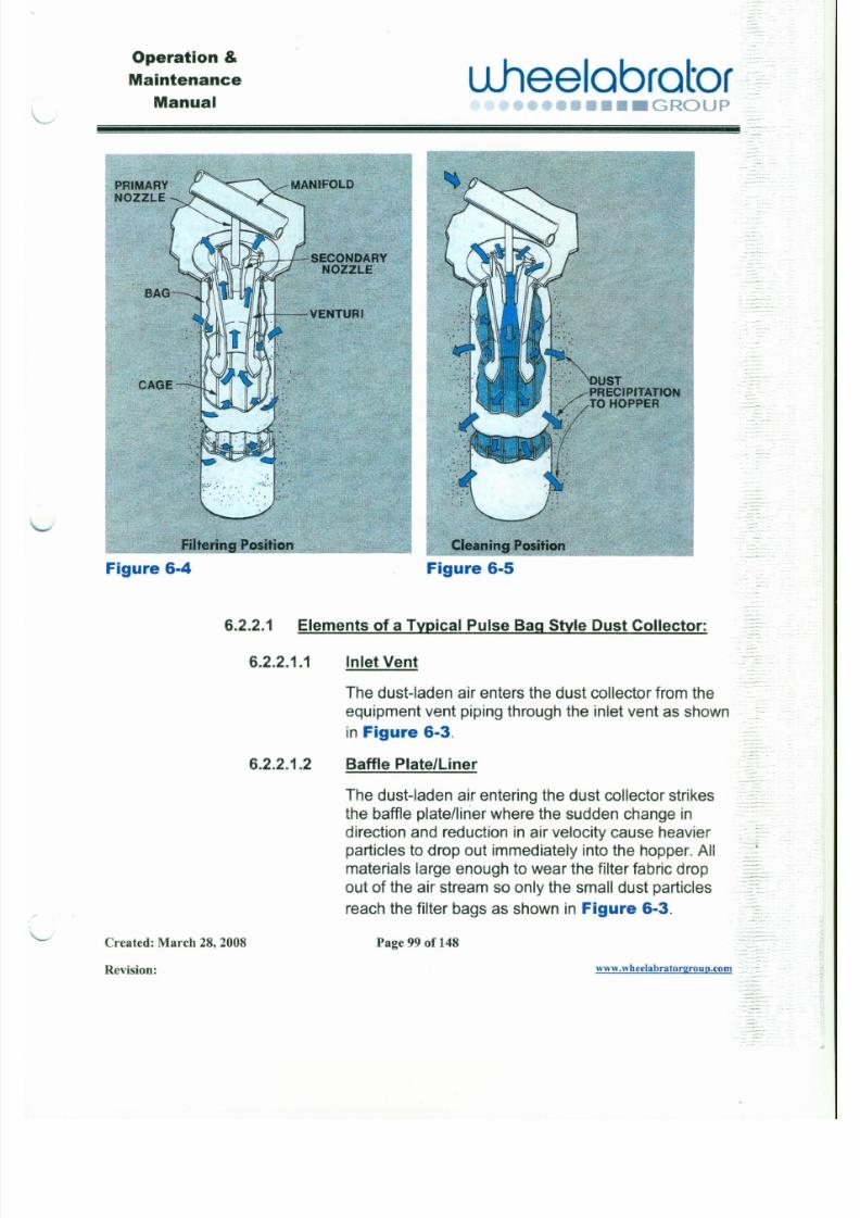
7/30/2019 MANUAL DE USUARIO GRANALLADORA (2).pdf
http://slidepdf.com/reader/full/manual-de-usuario-granalladora-2pdf 114/240
P R I MARYNOZZLE
T h U a ::tY - ' . 'S ECONDARYj J NOZzlE
Cleaning ,Position
Figure 6·5
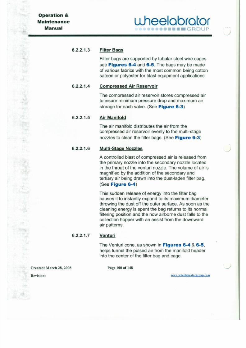
7/30/2019 MANUAL DE USUARIO GRANALLADORA (2).pdf
http://slidepdf.com/reader/full/manual-de-usuario-granalladora-2pdf 115/240
Operation &
Maintenance
Manualuhee l o b r o t o r
••••• GROUP. . . . . . . - '
6.2.2.1.8 Fan Outlet Vent
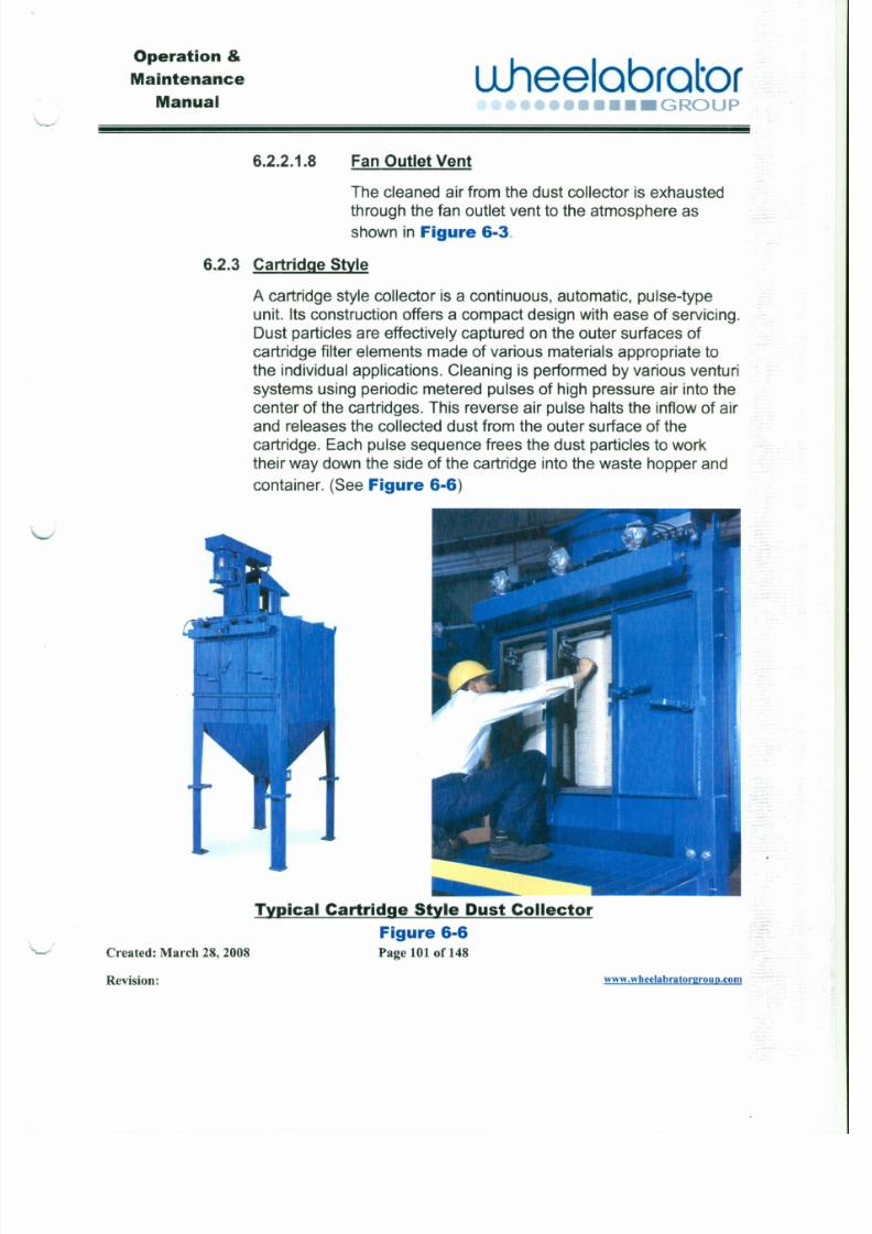
7/30/2019 MANUAL DE USUARIO GRANALLADORA (2).pdf
http://slidepdf.com/reader/full/manual-de-usuario-granalladora-2pdf 116/240
The cleaned air from the dust collector is exhaustedthrough the fan outlet vent to the atmosphere as
shown in Figure 6-3.
6.2.3 Cartr idge Style
A cartridge style collector is a continuous, automatic, pulse-typeunit. Its construction offers a compact design with ease of servicing.
Dust particles are effectively captured on the outer surfaces ofcartridge filter elements made of various materials appropriate to
the individual applications. Cleaning is performed by various venturi
systems using periodic metered pulses of high pressure air into thecenter of the cartridges. This reverse air pulse halts the inflow of airand releases the collected dust from the outer surface of thecartridge. Each pulse sequence frees the dust particles to work
their way down the side of the cartridge into the waste hopper and
container. (See Figure 6-6)
Operation &
Maintenance
Manual
u .hee lab ra to r••• GROUP
6.2.3.1 Elements of a Typical Cartridge Style Dust Collector:
,-.J
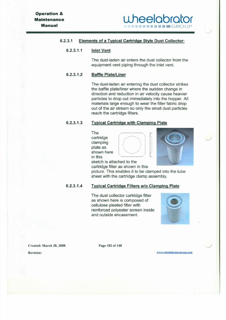
7/30/2019 MANUAL DE USUARIO GRANALLADORA (2).pdf
http://slidepdf.com/reader/full/manual-de-usuario-granalladora-2pdf 117/240
6.2.3.1.1
6.2.3.1.2
6.2.3.1.3
Inlet Vent
The dust-laden air enters the dust collector from theequipment vent piping through the inlet vent.
Baffle Plate/Liner
The dust-laden air entering the dust collector strikesthe baffle plate/liner where the sudden change indirection and reduction in air velocity cause heavier
particles to drop out immediately into the hopper. Allmaterials large enough to wear the filter fabric dropout of the air stream so only the small dust particlesreach the cartridge filters.
Typical Cartr idge with Clamping Plate
Thecartridgeclamping
plate asshown here O
·. .
. .
J
Operation &
Maintenance
Manual
" - - - - '
u .hee lab ra to r.uuu ••••• GROUP
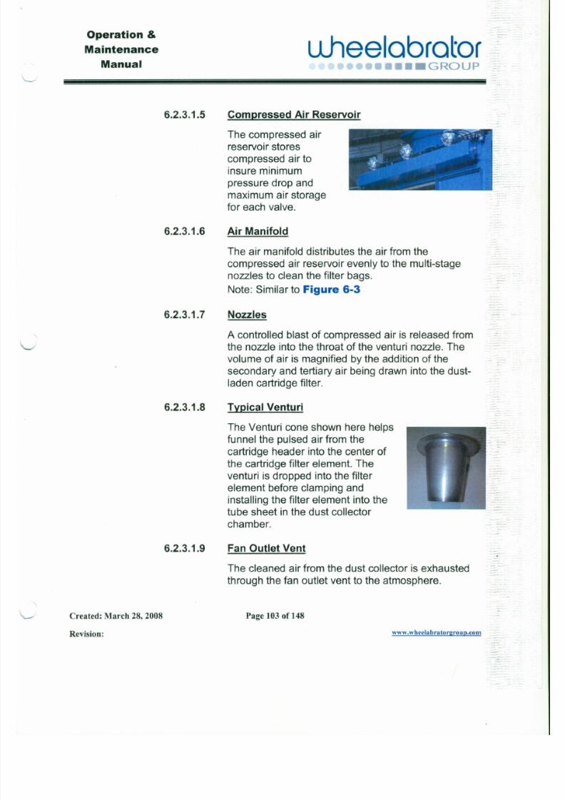
7/30/2019 MANUAL DE USUARIO GRANALLADORA (2).pdf
http://slidepdf.com/reader/full/manual-de-usuario-granalladora-2pdf 118/240
6 . 2 . 3 . 1 . 5 Compressed Ai r Reservoir0:
The compressed airreservoir stores
compressed air to
insure minimumpressure drop and
maximum air storage
for each valve.;
6 . 2 . 3 . 1 . 6 Air Manifold
The air manifold distributes the air from thecompressed air reservoir evenly to the multi-stagenozzles to clean the filter bags. _ . - -
•.
Note: Similar to Figure 6-3.. ,..,.
6 . 2 . 3 . 1 . 7 Nozzles'-- - -
A controlled blast of compressed air is released fromthe nozzle into the throat of the venturi nozzle. Thevolume of air is magnified by the addition of the
secondary and tertiary air being drawn into the dust-laden cartridge filter.
Operation &
Maintenance
Manual
uheelobrotor••• GROUP
J
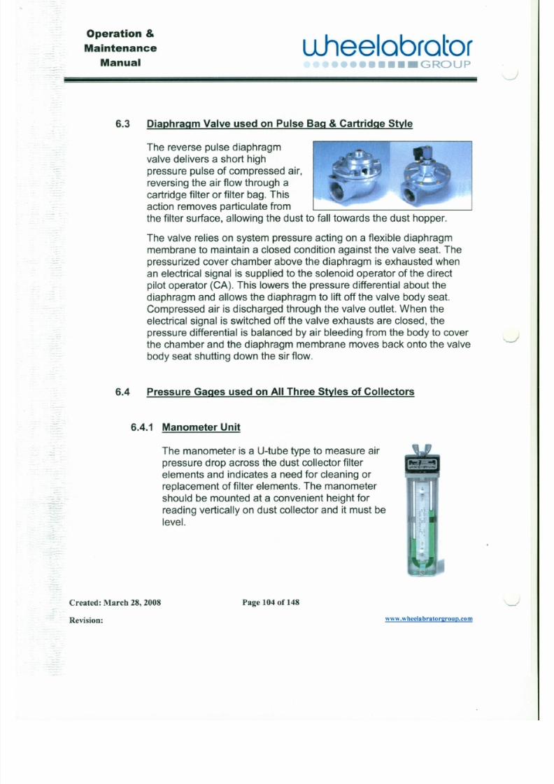
7/30/2019 MANUAL DE USUARIO GRANALLADORA (2).pdf
http://slidepdf.com/reader/full/manual-de-usuario-granalladora-2pdf 119/240
-:6.3 Diaphragm Valve used on Pulse Bag & Cartridge Style
The reverse pulse diaphragm
valve delivers a short high
pressure pulse of compressed air,
reversing the air flow through a
cartridge filter or filter bag. This
action removes particulate fromthe filter surface, allowing the dust to fall towards the dust hopper.
The valve relies on system pressure acting on a flexible diaphragmmembrane to maintain a closed condition against the valve seat. The
pressurized cover chamber above the diaphragm is exhausted when
an electrical signal is supplied to the solenoid operator of the directpilot operator (CA). This lowers the pressure differential about the
diaphragm and allows the diaphragm to lift off the valve body seat.Compressed air is discharged through the valve outlet. When the
electrical signal is switched off the valve exhausts are closed, thepressure differential is balanced by air bleeding from the body to coverthe chamber and the diaphragm membrane moves back onto the valve
body seat shutting down the sir flow.
Operation &
Maintenance
Manual
uheelobrctor'.•••• GROUP
'--
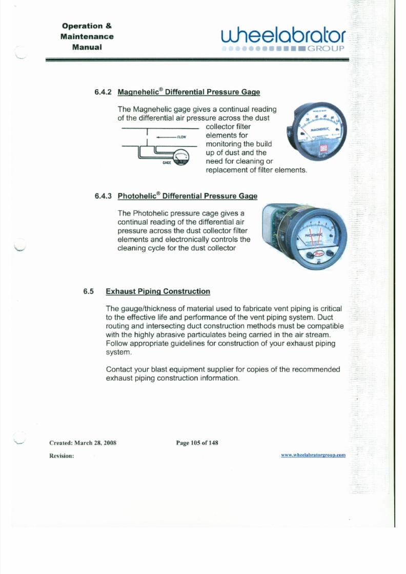
7/30/2019 MANUAL DE USUARIO GRANALLADORA (2).pdf
http://slidepdf.com/reader/full/manual-de-usuario-granalladora-2pdf 120/240
6.4.2 Magnehel ic@ Differential Pressure Gage
The Magnehelic gage gives a continual reading
of the differential air pressure across the dustcollector filter
elements formonitoring the build
up of dust and theneed for cleaning or
replacement of filter elements.
, FLOW
--T i:ieC A G E
6.4.3 Photohelic@ Dif ferential Pressure Gage
The Photohelic pressure cage gives a
continual reading of the differential airpressure across the dust collector filterelements and electronically controls thecleaning cycle for the dust collector
Operation &
Maintenance
Manual
L lhee lab ra to r•••• GROUP
" - -
Section 7 Operations

7/30/2019 MANUAL DE USUARIO GRANALLADORA (2).pdf
http://slidepdf.com/reader/full/manual-de-usuario-granalladora-2pdf 121/240
7.1 Functions of Cont rol Panel Ins truments
EXAMPLES:
7.1.1 Wheel RPM
The wheel RPM displays the rotations per minute that the blast
wheel is turning.
7.1.2 Wheel Amps
The ammeter measures the amperage that the blast wheel motor isdrawing. (Amperage is an indicator of amount of abrasive flow)
7.1.3 Abrasive Run Hours
The hour meter records blast time usage on the machine.(Preventive and predictive maintenance activity should be
scheduled based on hours of blast time)
7.1.4 Blast Timer
.s:
~
.:
Operation &
Maintenance
Manualuheelabrator
- -••• •••• GROUP
7.1.7 Emergency StopPushbutton
J
7/30/2019 MANUAL DE USUARIO GRANALLADORA (2).pdf
http://slidepdf.com/reader/full/manual-de-usuario-granalladora-2pdf 122/240
=
The emergency stop pushbutton shuts down the entire machine.(Stops the machine functions immediately)
Note: This is a push-pull maintained type button,
which is pushed for stopping and pulled to reset.
7.1.8 MotorOverload FaultLight
When this light is illuminated, a motor overload has tripped out.
7.1.9 Blast Start Pushbutton
Press the Blast Start pushbutton and the following occurs:
A. The door locks and the wheel starts.
B. After a small delay, abrasive begins to flow.
C. Blast timer begins to time.
D. When the timer times out, the wheel stops and abrasive
continues to flow to "brake" the wheel and the post tumble timer
begins to time.
I
.:»
Operation &
Maintenance
Manualuheelabrator
••••• GROUP~
7.1.12Wheel Start Pushbutton
'. ._ . .- ,-- - - -_ ." -

7/30/2019 MANUAL DE USUARIO GRANALLADORA (2).pdf
http://slidepdf.com/reader/full/manual-de-usuario-granalladora-2pdf 123/240
This pushbutton starts the blast wheel running when the equipmentis in the manual mode.
7.1.13Wheel Stop Pushbutton
This pushbutton shuts down the blast wheel when the equipment is
in the manual mode.
7.1.14 Blast Test Pushbutton
This pushbutton is used to take a blast pattern test.
7.1.15Abrasive Control Selector Switch
This selector switch enables or disables the flow of abrasive to theblast wheel.
7.2 Sequence of Operations
J an. 15,2007
J 3463 GUNDERSON-GIMSA
. -- - . . . . - ..
. . . . . . - -'" Operation &
Maintenance
Manual •••• ••• GROUP
uhee l ab ra t o r"', _ ., .- ' ..
5. Load the part on the entrance conveyor and press the "Conveyor Forward"push button. When the part is detected by the "Part detect" sensor located in
J
7/30/2019 MANUAL DE USUARIO GRANALLADORA (2).pdf
http://slidepdf.com/reader/full/manual-de-usuario-granalladora-2pdf 124/240
.-. "". front of the entrance vestibule the part tracking starts. If the part is inside theblasting zone the abrasive will turn on/off accordingly. If the part is inside thebrush-off zone the brush will turn on/off accordingly. If the part is inside theblow-off zone the blowers will turn on/off accordingly.
6. When the part reaches the "Over Travel" sensor located at the end of the exitconveyor, stops for unloading.
7. After unloading the blasted part and loading a new part, operator needs to
press the "Conveyor Forward" push button to continue the blasting.8. If for any reason the cabinet conveyor is stopped during the blast/brushprocess and restarted in reverse the part tracking is lost. The part must be
fully moved to the entrance conveyor and then sent back through the
machine.To run the part back to the entrance, operator can jog reverse the conveyor using
the entrance remote push button or the HMI screen button.9. When the reclaim system is running, if abrasive level is low in the upper
storage hopper, the abrasive adder control valve opens automatically to feedthe reclaim.
1D.lf the machine is on but no part is detected for an x time, the machine will shutdown automatically. The value of the auto shut down time is adjustable andpassword protected.
.. - , . _ - ..
IN MANUAL MODE (SET UP OR MAINTENANCE MODE):
J
Operation &
Maintenance
Manualuheelabrator
•••L••••• GROUP" - - - - - '
• There are two "Conveyor interrupt" push buttons located at entrance and
exit conveyors, for operator to stop the conveyors at any time without
7/30/2019 MANUAL DE USUARIO GRANALLADORA (2).pdf
http://slidepdf.com/reader/full/manual-de-usuario-granalladora-2pdf 125/240
disturbing the part tracking. The button which is pressed gets illuminated(flashing) while the other button stays solid on. To restart the conveyor,the button which is flashing has to be pressed again.
• If a motor overload is tripped, or any fault occurs the WHOLE MACHINE
WILL SHUT DOWN AND A FAULT MESSAGE WILL BE DISPLAYEDON THE HMI SCREEN.
7.3 Start-Up and Checkout
Before putting the equipment into operation, the following must beperformed:
1. Remove all foreign objects that might have been dropped or left inthe equipment such as the hoppers, elevator boot, inside the wheel
assembly, etc.2. Make sure that all covers, drive guards, inspection plates, etc. are
securely in place.
3. Check oil level of all the gear reducer drives. If required, fill with
manufacturer's recommendation listed on the reducer nameplate.
-
. • . . .
- •.- •.. ;.:::~:.
.,•. _ .. .:':~~:.. . . . . . . . • • . . _ . .
;--~.
Operation &
Maintenance
Manualu.heelabrator
•••• GROUP
..- _ .•. .. ; : : : :=
7.3.2 Charge the Eguipment with Media
-- - -- ./
7/30/2019 MANUAL DE USUARIO GRANALLADORA (2).pdf
http://slidepdf.com/reader/full/manual-de-usuario-granalladora-2pdf 126/240
. - ? :~ :~ :~ .
.. - .. .-~.
.--
-,_.'-
- ~ -.-
Before charging the Equipment, the blast gates on vent line fromthe cabinet, separator and elevator, should be set to one-half (1/2)open position. Final adjustment of the blast gates can be done later
when the ventilation system is balanced. Charge the equipmentwith the desired type and size of media. Load the abrasive material(media) slowly into the equipment.
After the media has been added, operate the blast wheel and
abrasive cycling system for 2 to 3 minutes. Stop blasting and letreclaim system return all the abrasive media to the storage hopper.If required add abrasive media until the level in storage hopper is 6"
to 8" below the adjustable lip under the swinging baffle in the
separator. As the equipment operates, check to insure that onlyfines, sand and/or scale is coming out of the dribble valve on the
separator refuse spout. If usable abrasive media is coming out ofthe dribble valve, verify correct (full curtain) operation of the
separator and adjust the blast gate in the vent line to reduce the airflow through the separator slightly. Also check for abrasive leakagearound the equipment.
7.3.3 Blast Wheel
See Section 4, Blast Wheel, for setting up and operation of the
J
Operation &
Maintenance
Manualuheeloorotor
••• GROUP
Section 8 Maintenance

7/30/2019 MANUAL DE USUARIO GRANALLADORA (2).pdf
http://slidepdf.com/reader/full/manual-de-usuario-granalladora-2pdf 127/240
8.1 Inspection, Repair/Replacement of Parts & Components
For the blast equipment to perform efficiently, periodic inspection and
preventive and predictive maintenance must be accomplished througha regular maintenance program, "Have a Good program and PracticeIt." The purpose of this program is:
1) To detect minor necessary repairs and prevent major ones.
2) To anticipate repairs by locating probable causes - i.e., p..reventive·t ~main enance.
3) To plan repairs for convenient times (pre
4) To prevent breakdowns.
5) To be certain that the machine is being operated safely and at the
highest possible efficiency level.6) To keep an accurate record of maintenance activity and
replacement parts usage in order to manage the spare partsinventory and monitor operating and maintenance costs.
CAUTION: When performing inspection and
: .-
.. ::
=
-= .
-
-----,,,- Operation &
L1hee labra to r- -
Maintenance
- Manual .......•......................,......,.n.GROUp
,J
: : : .
8.1.1.1 Liners-z,
7/30/2019 MANUAL DE USUARIO GRANALLADORA (2).pdf
http://slidepdf.com/reader/full/manual-de-usuario-granalladora-2pdf 128/240
The liners should be inspected and replaced before anyholes are worn through. All liners are easy to replace. When
installing liners in the wheel housing, it is vitally importantthat the liner pieces fit up against one another as tightly as
. possible to minimize housing wear from the blast.
_ . _ . -8.1.1.2 Wheel Housing
- During replacement of liners, the housing should beinspected for wear. A defective housing should be repaired
or replaced promptly to prevent the escape of abrasive
media.
8.1.1.3 Wheel Blades, Control Cage & Impeller•..- - .
The wheel parts should be inspected at the same time thatliner inspection is made. Parts should be replaced whenworn in accordance with the following criteria:
-- One of the main objects of wheel assembly inspection and
maintenance is to keep the wheel in balance. Severe
vibration can be a major cause of motor bearing failure.
Operation &
Maintenance
Manual
_ ..
uheelobrotor••••• GROUP
" - . , . /
To replace the control cage and impeller, remove the feed
spout and control cage clamps. Remove impeller cap screw
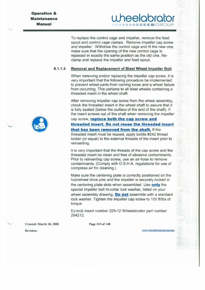
7/30/2019 MANUAL DE USUARIO GRANALLADORA (2).pdf
http://slidepdf.com/reader/full/manual-de-usuario-granalladora-2pdf 129/240
and impeller. Withdraw the control cage and fit the new one,
make sure that the opening of the new control cage isreplaced in exactly the same position as the old one. Re-
clamp and replace the impeller and feed spout.
8.1.1.4 Removal and Replacement of Blast Wheel Impeller Bolt ." _.__
&)
When removing and/or replacing the impeller cap screw, it isvery important that the following procedure be implemented
to prevent wheel parts from coming loose and a wheel failure
from occurring. This pertains to all blast wheels containing athreaded insert in the wheel shaft.
After removing impeller cap screw from the wheel assembly,
check the threaded insert in the wheel shaft to assure that itis fully seated (below the surface of the end of the shaft). If
the insert screws out of the shaft when removing the impeller
cap screw, replace both the cap screw and
threaded insert. Do not reuse the threaded insert
that has been removed from the shaft. If the
threaded insert must be reused, apply loctite #242 threadlocker (or equal) to the external threads of the insert prior to
. -~-= - ::--~.,---..,..
"-~:,:=~:::
Operation &
Maintenance
Manual
ulleelabrator•••• GROUP
._- -. __.' iii!iiiiiiii~~~~~~~~~~~~~~~~~~~!!ii!l
8.1.2 Cabinet Assembly
J
7/30/2019 MANUAL DE USUARIO GRANALLADORA (2).pdf
http://slidepdf.com/reader/full/manual-de-usuario-granalladora-2pdf 130/240
At regular inspection intervals, the inside surfaces of the cabinetshould be inspected to detect any wear points that could lead to
structural damage or abrasive leakage. If abnormal wear occurs,
immediate action should be taken to determine the cause and
make necessary repairs/replacement. All liners should be inspectedand replaced before any holes are worn through. Any worn or
damaged components should be replaced to prevent structuraldamage and leakage of abrasive.
8.1.3 Work Conveyor Assembly
Regular inspection should be given to the work conveyor structure,bearings, and alignment.
8.1.4 Work Conveyor Drive Assembly
The work conveyor drive should be checked for alignment andproper operation. The gear motor should be checked for oil level.If required, refer to gear motor's instruction sheet in Commercial
Parts Manuals, Section 10 for proper lubricant. Refer to Section 8,
Paragraph 8.2 for recommendations on lubricating machine
--J
~
......
Operation &
Maintenance
Manual
u .hee lab ra to r••••••••• GROUP
" - - -
8.1.5.1 Abrasive Hopper
7/30/2019 MANUAL DE USUARIO GRANALLADORA (2).pdf
http://slidepdf.com/reader/full/manual-de-usuario-granalladora-2pdf 131/240
Inspection of the sloping sides of the hopper should be madeat regular intervals to detect any wear points. Immediaterepair/replacement of sections worn away or damaged is
necessary to minimize loss of abrasive and any disruption incycling of the abrasive. Periodically, clean the hopper screen
of accumulated objects and debris.
8.1.5.2 Elevator Belt AssemblyThe elevator belt assembly should be checked for wear or
damage to the belt, worn or damaged buckets, propertension of the belt and proper alignment on the head pulley.
Normally, a new belt assembly is required to replace a wornor damaged elevator belt assembly.
Buckets are the bolt-on type and easily replaced. Check
condition of bolt heads for damage and wear. Badly wornbolt heads can lead to the buckets pulling off of the belt. All
buckets should be inspected periodically for wear or
damage. They should be replaced when the front lip of thebuckets wear down 3/4 inch.
Operation &
u .hee lab ra to raintenance..-'
Manual ~., , . . . . . . . , . . . . , . . . , . . . . t
••• GROUP
- J
- When a worn elevator belt needs replacement, remove theelevator side panel at the boot of the elevator to undo the
7/30/2019 MANUAL DE USUARIO GRANALLADORA (2).pdf
http://slidepdf.com/reader/full/manual-de-usuario-granalladora-2pdf 132/240
- - splice and carefully take out the old belt. You may use theold belt to help pull in the new belt if desired. See note
-- below. Since every belt is "tailor" fitted to each individual
elevator assembly, the new belt supplied will probably be 4":.
to 8" longer than needed. To determine the correct beltlength required, measure the distance of the path of the belt
__ "M
around both top and bottom pulleys. Make sure that the.- head pulley is lowered to the lowest position at the time of
. - measurement. Cut-off must be square. This will result in a
tight belt to begin with and allow ample take-up for future
needed tension. After the belt is cut, punch in the holes for
.- the splice and bolt the splice on one end of the belt only.
-- , Note: While the belt is out of the machine, inspect the bootpulley and head pulley and bearings for wear or damage.Replace any defective parts. The belt assembly can be fed
into the elevator housing through the bottom panel openingand pulled up and over the top pulley (use the old belt or
,- rope wrapped over the top (head) pulley), making sure thatJthe buckets are headed in the proper direction for discharge
- of abrasive into the elevator from the top and fed down thesides of the head pulley. After the belt is "hung" on the top
Operation &
L1hee labra toraintenance
Manual ·" ......•...••••••• GROUP~/
.•
.-
Belt tension can be adjusted by the screw take-uparrangement at the head section of the elevator. The
7/30/2019 MANUAL DE USUARIO GRANALLADORA (2).pdf
http://slidepdf.com/reader/full/manual-de-usuario-granalladora-2pdf 133/240
head pulley can be raised or lowered, within the_ . 4 .
mechanical take-up limits, by the take-up bolts. .-
Inspection of the elevator belt alignment is veryimportant. If the belt is permitted to run off center and rub
against the elevator housing, the abrading action will
eventually damage the elevator housing and belt. Also,
an overload is put on the drive motor, which may causethe overload relays to kick out. A take-up screw is
provided on each side of the head shaft for maintaining.-.
proper alignment. When aligning the elevator belt, make
only a slight adjustment at a time, raising the head shafton the side toward which the belt is riding. Using caution
and keeping hands away from top opening, the top coverplate can be removed to permit viewing the belt
alignment on the head pulley while the belt is running. . -.Refer to Section 9 "Troubleshooting" for elevatormalfunctions and suggested remedies.
8 . 1 . 5 . 3 Elevator Drive
The gear motor for the elevator drive should be checked for
Operation &
Maintenance
ManualLlheelabrator
•••••• GROUP
8.1.5.6 Bearings
.J
7/30/2019 MANUAL DE USUARIO GRANALLADORA (2).pdf
http://slidepdf.com/reader/full/manual-de-usuario-granalladora-2pdf 134/240
e
-
-
The bearings should be checked for wear. If serious bearingwear is evident the bearings should be replaced. Most
bearings are lubricated for life and do not require
lubrication.
8.1.5.7 CFS Separator Assembly
The purpose of the separator is to remove scale, dust and
other fine materials from the usable shot (media). Thisseparation is extremely important, since failure to removethese contaminants from the media will not only decrease
the productivity (cleaning capability) of the machine, but willalso increase the rate of wear on the machine and maycause dust build up on parts.
The satisfactory performance of the machine is dependent
on the proper adjustment and maintenance of the separator.It is of utmost importance that the operation be constantly
checked. Particular attention should be given to the flow ofabrasive as it passes through the separator baffle assembly.The separator assembly should be adjusted so that auniformly thick falling stream of abrasive material is spread
across the full width of the separator. This insures that the
J
·. . .. . .. .
-
Operation &
uJ lee lab ra to raintenance
Manual .. "r.,... •.....r -, •• •• • GROUP
' - - - - - "
The components of the separator are subject to very little
wear. However, they should be inspected periodically and
7/30/2019 MANUAL DE USUARIO GRANALLADORA (2).pdf
http://slidepdf.com/reader/full/manual-de-usuario-granalladora-2pdf 135/240
any damaged components should be repaired or replaced." . .-
Refer to Section 9.3 "Troubleshooting" for separator . M . .• _ '
malfunctions and remedies.
WARNING: If tramp metal or large
particles fall into the storage hopper and
enter the wheel, the wheel components
may shatter and clause severe damage or
possible injury.
8.1.6 Ventilation System - Provided by customer or as an option
-.-The ventilation system requires regular inspection of parts andcomponents to insure design performance, and to insure that an --adequate flow of air exists and is maintained.
The vent piping from the machine to the dust collector should be ..
checked periodically for wear and leaks. Replace or repair defective-.
Operation &
Maintenance
Manual
uheelcorotor•••• GROUP
.-
. . _ ••. . f ! ! ! ! . ~~ ~ ~ ~ ~ ~ ~ ~ ~ ~ ~~ ~~ ~ ~ ~ ~ ~
For the machine to perform efficiently, the electrical equipmentmust undergo periodic inspection to detect any wear conditions,
J
7/30/2019 MANUAL DE USUARIO GRANALLADORA (2).pdf
http://slidepdf.com/reader/full/manual-de-usuario-granalladora-2pdf 136/240
-:
physical damage, loose connections or component failure. Refer toSection 9 ''Troubleshooting'' for electrical equipment malfunctions
and remedies. Regular maintenance inspections should beperformed with particular emphasis on the following:
8.1.7.1 Control Panel
Check out electrical wires and connections for looseness,
damage and proper insulation. Tighten, repair or replace.
8.1.7.2 Electric Motors
Periodically inspect the motors for excessive dirt, vibration,
or abnormal conditions. Clean, correct, or replace asnecessary. Keep the ventilation openings of the motor clearto allow free passage of air.
If excessive friction and overheating of bearings is noted, it isusually caused by the following factors:
1) Bent motor shaft
2) Poor alignment
J
Operation &
Maintenance
Manual
uheeloorotor:"- ./
••••••••• GROUP .:
8.2 Lubricat ion-Oi l & Grease
7/30/2019 MANUAL DE USUARIO GRANALLADORA (2).pdf
http://slidepdf.com/reader/full/manual-de-usuario-granalladora-2pdf 137/240
o
The life and performance of many components of the equipment aredependent on proper lubrication of components. Most bearings are
lube for life and do not require lubrication. Only electric motors and
reducers will require lubrication. Thorough lubrication, performed at
regular intervals will aid greatly in prolonging the life of the machinecomponents and in improving efficiency of operation.
Note: The intervals of lubrication are based on normal
operating conditions. If severe operating conditions
exist, such as extremely dusty conditions or an abnormal
amount of stopping and starting, it may be necessary to
perform the lubrication more frequently.
While lubrication of the required components is essential, lubrication ofsome drive components of blast cleaning equipment can be
detrimental. For example, chains and sprockets should not be
lubricated with petroleum base material because the lubricant tends to
accumulate metallic dust in the environment. This causes excessive
wear on the chains and sprockets.
The following recommendations should be followed when lubricating
Operation &
Maintenance
Manual
uheelobrotor.•••• GROUP
Section-9 Troubleshooting
Before attempting any troubleshooting, maintenance personnel and . _ -
7/30/2019 MANUAL DE USUARIO GRANALLADORA (2).pdf
http://slidepdf.com/reader/full/manual-de-usuario-granalladora-2pdf 138/240
eoperating personnel should become thoroughly familiar with theequipment.
Follow your Lockout/Tagout procedure (See Safety -
Warning & Precautions Section)
Before making any repair or replacement of defective parts, it is very
important that the reason for the original failure be determined and
corrected. A failure to correct the cause of the problem will inevitably lead
to a reoccurrence of the problem, etc.
Blast equipment will often continue to operate and will do an acceptable
job even though some of the mechanisms or components are not
functioning properly causing a decrease in efficiency. It is important formaximum efficiency, that troubleshooting be performed if either of the
following is noted:
1) Increase in abrasive consumption,
2) Decrease in cleaning efficiency.
Operation &
Maintenance
Manual
u .hee lab ra to r••• •••• GROUP
-.-..~~~~~~~~~~~~~~~~~~~~~._ -
Trouble Probable Cause Possible Remedy
.-....../ .
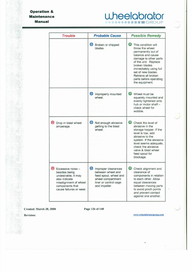
7/30/2019 MANUAL DE USUARIO GRANALLADORA (2).pdf
http://slidepdf.com/reader/full/manual-de-usuario-granalladora-2pdf 139/240
- . .. . -
@ Broken or chipped @ This condition will
blades. throw the wheel
permanently out of
balance and cause
damage to other partsof the unit. Replace
broken blades
immediately using full
set of new blades.
Retrieve all brokenparts before operatingthe equipment.
@ Improperly mounted @ Wheel must bewheel. squarely mounted and
evenly tightened ontohub or motor shaft -
check wheel for
wobble.
® Drop in blast wheel @ Not enough abrasive @ Check the level of
amperage. getting to the blast abrasive in thewheel. storage hopper. If the
J
Operation &
Maintenance
Manual
L1hee labra tor••••••••• GROUP
Trouble Probable Cause Possible Remedy
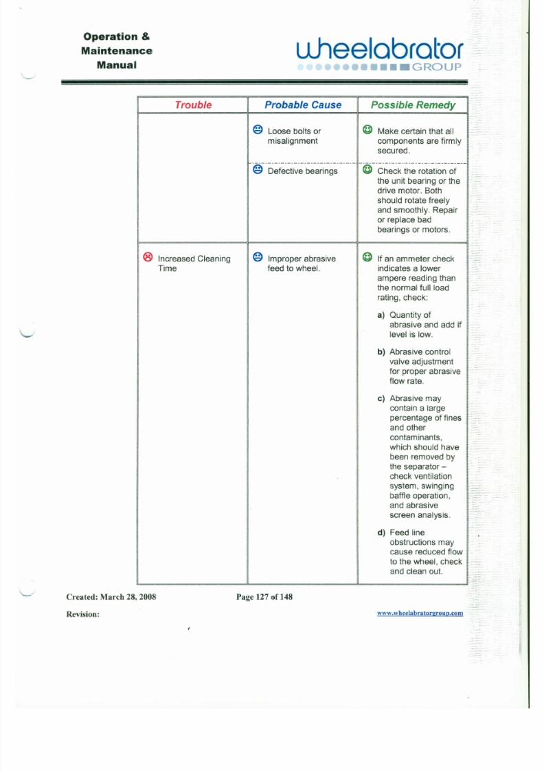
7/30/2019 MANUAL DE USUARIO GRANALLADORA (2).pdf
http://slidepdf.com/reader/full/manual-de-usuario-granalladora-2pdf 140/240
@ Loose bolts or @ Make certain that all
misalignment components are firmly
secured.
@-D~f~-~ti~~-b~-~~~~~------ -@--Ch~-~k-th~-~~t;ti~~-~---
the unit bearing or the
drive motor. Both
should rotate freely
and smoothly. Repairor replace bad
bearings or motors.
® Increased Cleaning @ Improper abrasive @ If an ammeter check
Time feed to wheel. indicates a lowerampere reading than
the normal full load
rating, check:
a) Quantity of
abrasive and add if
level is low.
b) Abrasive control
valve adjustment
Operation &
Maintenance
Manual
u .hee lab ra to r••••••••• GROUP
Trouble Probable Cause Possible Remedy
@ Loss of Directional @ Conduct a blast
J
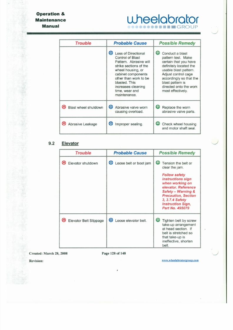
7/30/2019 MANUAL DE USUARIO GRANALLADORA (2).pdf
http://slidepdf.com/reader/full/manual-de-usuario-granalladora-2pdf 141/240
Control of Blast pattern test. Make
Pattern. Abrasive will certain that you have
strike sections of the definitely located the
wheel housing, or usable blast pattern.
cabinet components Adjust control cage
other than work to be accordingly so that the
blasted. This blast pattern is
increases cleaning directed onto the work
time, wear and most effectively.maintenance.
® Blast wheel shutdown @ Abrasive valve worn @ Replace the worn
causing overload. abrasive valve parts.
® Abrasive Leakage @ Improper sealing. @ Check wheel housing
and motor shaft seal.
9.2 Elevator
Trouble Probable Cause Possible Remedy
Operation &
Maintenance
ManualL lhee lab ra to r
•••••••••• GROUP~
Trouble I Probable Cause I Possible Remedy
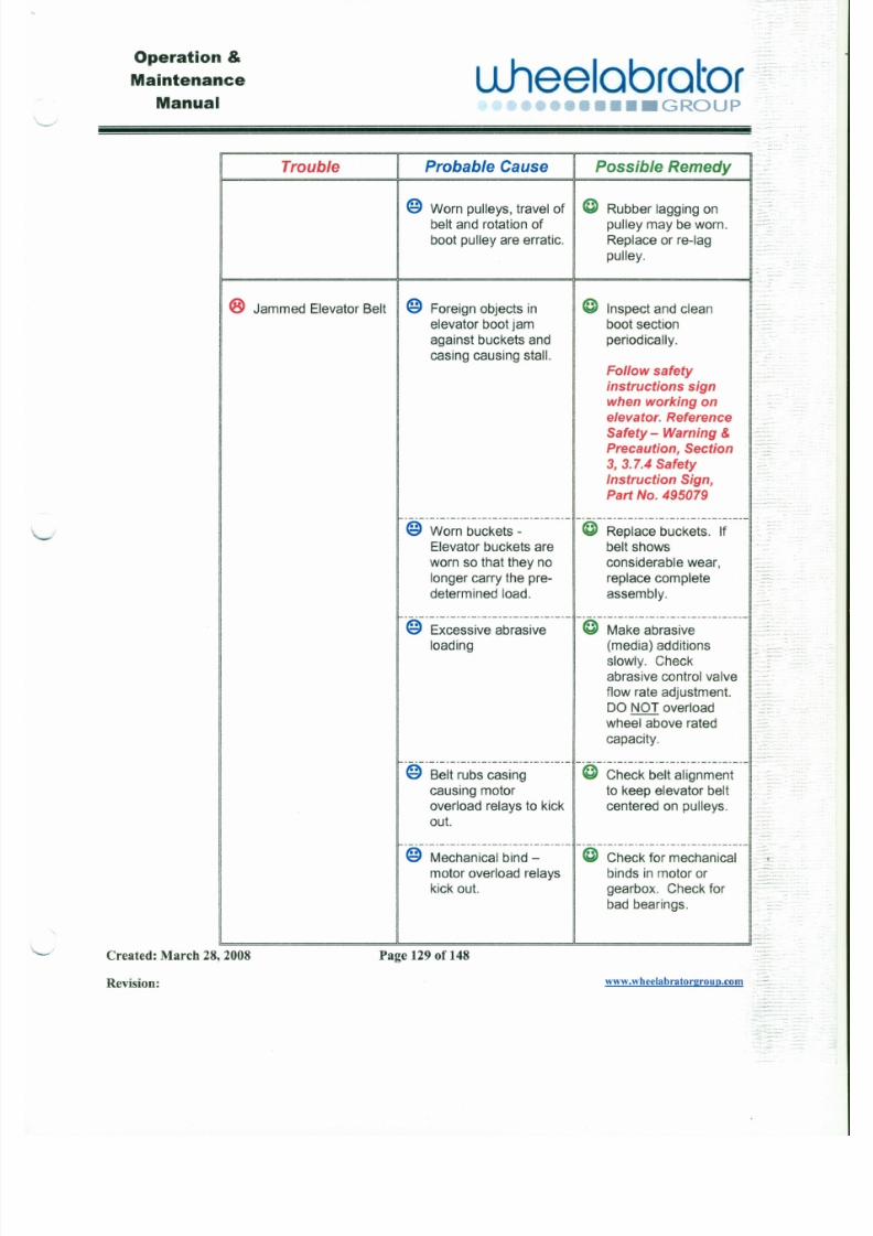
7/30/2019 MANUAL DE USUARIO GRANALLADORA (2).pdf
http://slidepdf.com/reader/full/manual-de-usuario-granalladora-2pdf 142/240
@ Worn pulleys, travel of @ Rubber lagging on
belt and rotation of pulley may be worn.
boot pulley are erratic. Replace or re-Iag
pulley.
® J ammed Elevator Belt @ Foreign objects in @ Inspect and clean
elevator boot jam boot section
against buckets and periodically.casing causing stall.
Follow safety
instructions sign
when working on
elevator. Reference
Safety - Warning &
Precaution, Section
3, 3.7.4 Safety
Instruction Sign,Part No. 495079
- - - - - - - - - - - - - - - - - - - - - - - - - - - - - - - --@--R;~;~~-b-~~k;t~:-if----@ Worn buckets-
Elevator buckets are belt showsworn so that they no considerable wear,
longer carry the pre- replace complete
determined load. assembly.
Operation &
Maintenance
Manual
L ihee lab ra to r•••••• GROUP
Trouble Probable Cause Possible Remedy
@ Abrasive control valve @ Lack of air pressure to
J
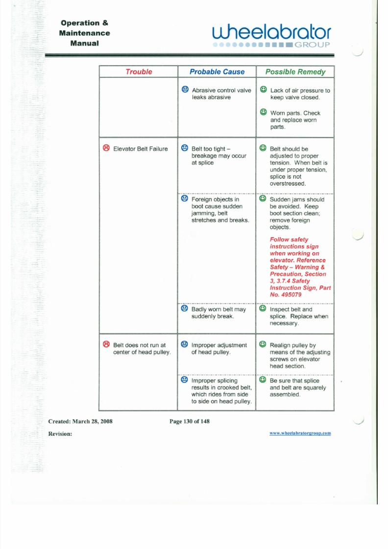
7/30/2019 MANUAL DE USUARIO GRANALLADORA (2).pdf
http://slidepdf.com/reader/full/manual-de-usuario-granalladora-2pdf 143/240
leaks abrasive keep valve closed.
@ Worn parts. Check
and replace worn
parts.
® Elevator Belt Failure @ Belt too tight - @ Belt should bebreakage may occur adjusted to properat splice tension. When belt is
under proper tension,
splice is not
overstressed.
- - - - - - - - - - - - - - - - - - - - - - - - - - - - - - - - - - - - - - - - - - - - - - - - - - - - - - - - - - - - - - - - -@ Foreign objects in @ Sudden jams should
boot cause sudden be avoided. Keep
jamming, belt boot section clean;stretches and breaks. remove foreign
objects.
Follow safety
instructions sign
when working on
elevator. Reference
Operation &
Maintenance
Manual
u .hee lab ra to r••••• GROUP
"- -
Trouble Probable Cause Possible Remedy
@ Worn crown on head @ Check head pulley.
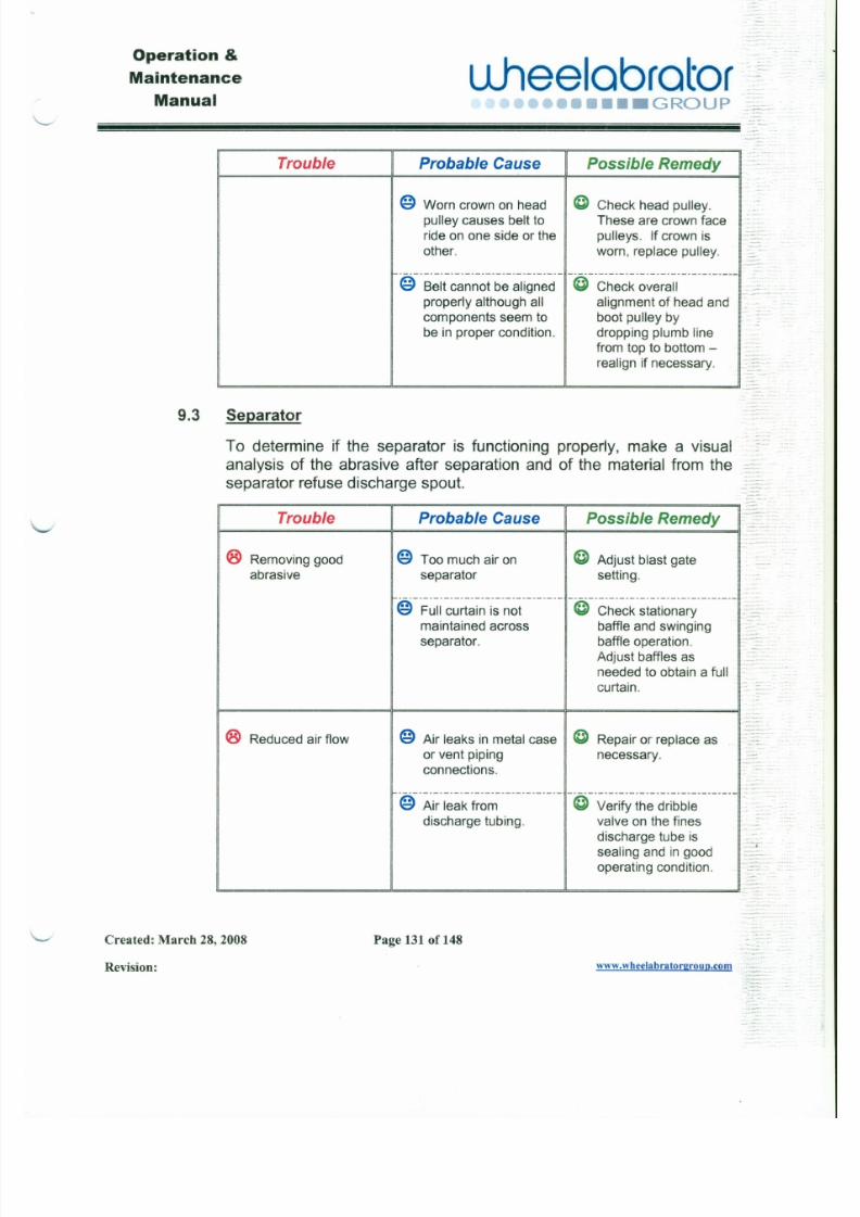
7/30/2019 MANUAL DE USUARIO GRANALLADORA (2).pdf
http://slidepdf.com/reader/full/manual-de-usuario-granalladora-2pdf 144/240
Trouble Probable Cause Possible Remedy
® Removing good @ Too much air on @ Adjust blast gateabrasive separator setting.
pulley causes belt to These are crown faceride on one side or the pulleys. If crown isother. worn, replace pulley.
- - - - - - - - - - - - - - - - - - - - - - - - - - - - - - - - -(f·C·h~~k·~;~~~I·-·-·-·-----@ Belt cannot be aligned
properly although all alignment of head and
components seem to boot pulley by
be in proper condition. dropping plumb linefrom top to bottom -
realign if necessary.
9 . 3 Separator
To determine if the separator is functioning properly, make a visualanalysis of the abrasive after separation and of the material from the:::
separator refusedischarge spout.~:~~
Operation &Maintenance
Manualuheelabrator
•••••••• GROUP
. _ . . ~!!!!i!ii i i i i!i!!!!!i!ii i i i i!i!!!!!i!ii i i i i!i!!!!!i!ii i i ii! i!!!!!i!ii i i i i!i!!!!!i!ii i i i i!i!!!!!i!ii i i i i!i!!!!!i!ii i i i i!i!!!!!i!ii i i i i!i!!!!!i!ii i i i i!i!!!!!i!ii i i i i!i!!!!!i!ii i i i i!i!!!!!i!ii i i i i!i!!!!!i!ii i i i i!i!!!!!i!ii i i i i!i!!!!!i!ii i i i i!i!!!!!i!ii i i i i!i!!!!!i!ii i i i i!i!!!!!i!ii i i i i!i!!!!!i!ii i i i i!i!!!!!i!ii i i i i!i!!!!i!ii!!i!!i!
Trouble Probable Cause Possible Remedy
® Contaminated @ Insufficient flow of air @ Adjust blast gate
J
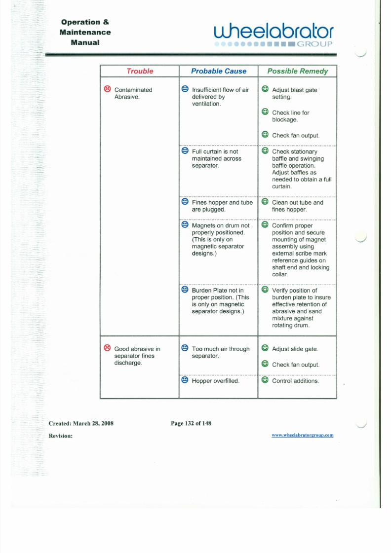
7/30/2019 MANUAL DE USUARIO GRANALLADORA (2).pdf
http://slidepdf.com/reader/full/manual-de-usuario-granalladora-2pdf 145/240
Abrasive. delivered by setting.
ventilation.
@ Check line for
blockage.
@ Check fan output.
- - - - - - - - - - - - - - - - - - - - - - - - - - - - - - - - - - - - - - - - - - - - - - - - - - - - - - - - - - - - - - - - -
@ Full curtain is not @ Check stationarymaintained across baffle and swingingseparator. baffle operation.
Adjust baffles asneeded to obtain a full
curtain.
- - - - - - - - - - - - - - - - - - - - - - - - - - - - - - - - - - - - - - - - - - - - - - - - - - - - - - - - - - - - - - - - -@ Fines hopper and tube @ Clean out tube and
are plugged. fines hopper.
- - - - - - - - - - - - - - - - - - - - - - - - - - - - - - - - - - - - - - - - - - - - - - - - - - - - - - - - - - - - - - - - -@ Magnets on drum not @ Confirm proper
properly positioned. position and secure(This is only on mounting of magnetmagnetic separator assembly using
designs.) external scribe mark
reference guides on
Operation &
Maintenance
Manual" - - - - "
uheelobrctor.••••• GROUP
Trouble Possible Remedyrobable Cause
@ Magnets on drum not @ Confirm proper

7/30/2019 MANUAL DE USUARIO GRANALLADORA (2).pdf
http://slidepdf.com/reader/full/manual-de-usuario-granalladora-2pdf 146/240
properly positioned.
(This is only on
magnetic separator
designs.)
position and secure
mounting of magnet
assembly usingexternal scribe mark
reference guides on
shaft end and lockingcollar.
@ -·B~-;d~-~-P l~t~-~-~t·i~·-·-·-@ -·V~~ify-~~~iti~~-~f·-·-·-·-proper position. (This burden plate to insure
is only on magnetic effective retention of
separator designs.) abrasive and sand
mixture against
rotating drum.
-
Ventilation System
Proper maintenance of the ventilation system is just as important asthe servicinq of other elements of the blastequipment.
The following troubleshooting chart is provided as an aid formaintaining adequate and efficient ventilation.
9.4
Operation &Maintenance
Manual
L1hee labra to r••••• GROUP
-- .....~~~~~~~~~~~~~~~~~~~!!!l!!
Trouble Probable Cause Possible Remedy
@ Check dust collector
-J
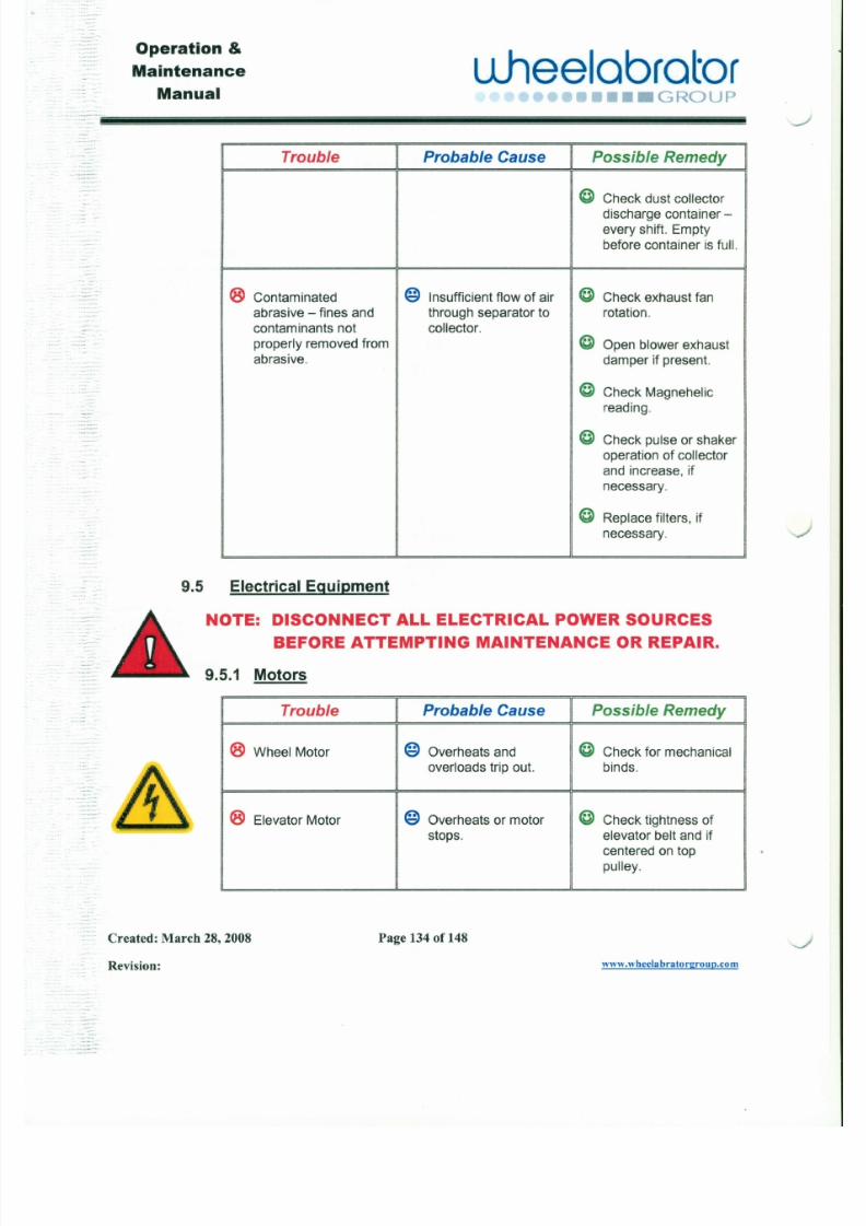
7/30/2019 MANUAL DE USUARIO GRANALLADORA (2).pdf
http://slidepdf.com/reader/full/manual-de-usuario-granalladora-2pdf 147/240
discharge container -
every shift. Emptybefore container is full.
® Contaminated @ Insufficient flow of air @ Check exhaust fan
abrasive - fines and through separator to rotation.
contaminants not collector.
properly removed from @ Open blower exhaustabrasive. damper if present.
@ Check Magnehelic
reading.
@ Check pulse or shakeroperation of collector
and increase, if
necessary.
@ Replace filters, if
necessary.
9.5 Electrical Equipment
Operation &
Maintenance
ManualuJ1ee labra to r
••••••••• GROUp·:
Trouble Probable Cause Possible Remedy
@ Check main power® Electric Motors do not @ Main power cable
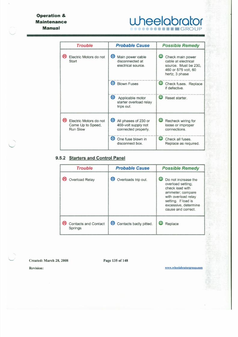
7/30/2019 MANUAL DE USUARIO GRANALLADORA (2).pdf
http://slidepdf.com/reader/full/manual-de-usuario-granalladora-2pdf 148/240
cable at electrical
source. Must be 230,
460 or 575 volt, 60hertz, 3 phase
- - - - - - - - - - - - - - - - - - - - - - - - - - - - - - - - 1 - - - - - - - - - - - - - - - - - - - - - - - - - - - - - - _@ Blown Fuses I I @ Check fuses. Replace
if defective.
@ Applicable motor I I @ Reset starter.
starter overload relaytrips out.
- - - - - - - - - - - - - - - - - - - - - - - - - - - - - - - - ~ - - - - - - - - - - - - - - - - - - - - - . _ - - - - - _ . _ . - . . . . -@ One fuse blown in @ Check all fuses.
disconnect box. Replace as required. I"~
Start disconnected at
electrical source.
@ All phases of 230 or
460-volt supply not
connected properly.
® Electric Motors do not
Come Up to Speed,
Run Slow
9.5.2 Starters and Contro l Panel
@ Recheck wiring for
loose or improperconnections.
Operation &Maintenance
Manualuheelcbrotor
••••• GROUP
---".~~~~~~~~~~~~~~~~~~~~~~ii!i!i!!!i!!i!
Trouble Probable Cause Possible Remedy
® Fuse Protection @ Fuses blow. @ For the occasional
<:»
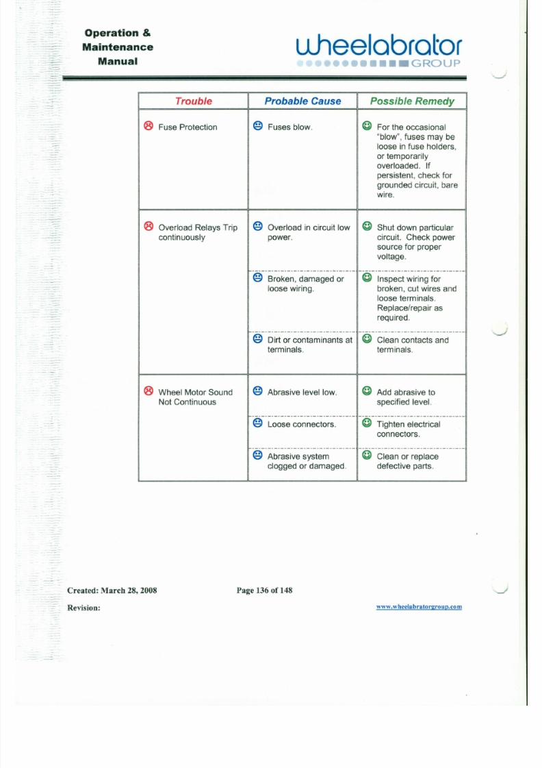
7/30/2019 MANUAL DE USUARIO GRANALLADORA (2).pdf
http://slidepdf.com/reader/full/manual-de-usuario-granalladora-2pdf 149/240
"blow", fuses may be
loose in fuse holders,
or temporarilyoverloaded. If
persistent, check for
grounded circuit, barewire.
® Overload Relays Trip @ Overload in circuit low @ Shut down particular
continuously power. circuit. Check power
source for proper
voltage.
- - - - - - - - - - - - - - - - - - - - - - - - - - - - - - - - - - - - - - - - - - - - - - - - - - - - - - - - - - - - - - - - -@ Broken, damaged or @ Inspect wiring for
loose wiring. broken, cut wires and
loose terminals.
Replace/repair as
required.
- - - - - - - - - - - - - - - - - - - - - - - - - - - - - - . - - - - - - - - - - - - - - - - - - - - - - - - - - - - - - - - - -@ Dirt or contaminants at @ Clean contacts and
terminals. terminals.
Operation &
Maintenance
Manual
ulleelabrator•••••••• GROUP
Probable Cause
9.5.3 Cont ro l Accessories - Operator's Control Panel
Trouble Possible Remedy
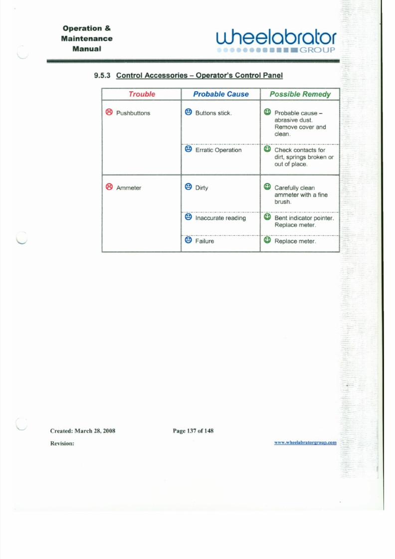
7/30/2019 MANUAL DE USUARIO GRANALLADORA (2).pdf
http://slidepdf.com/reader/full/manual-de-usuario-granalladora-2pdf 150/240
@ Buttons stick.
@ Dirty
@ Failure
® Pushbuttons
.. _ - - - - - - - - - - - - - - - - - - - - - _ . _ . _ - - ) _ . _ - - - - - - - - - _ . _ - - - _ . - . _ . _ . _ . _ . _ . - . -
@ Erratic Operation @ Check contacts for
dirt, springs broken orout of place.
@ Probable cause -abrasive dust.
Remove cover and
clean .
1
_:
,-
® Ammeter-
· - · - - - · - · - · - · - · - · - · - · - · - - - - - - - - - n - - - - - - - - - - - - - - - - - - - - - - - - - - - - - - - . -
@ Inaccurate reading i@ Bent indicator pointer.Replace meter.
@ Carefully clean
ammeter with a fine
brush.
@ Replace meter.
Commercial LocationPart Model on Web Address for Manual
Operation &
Maintenance
Manual
Llheelabrator ~ =••••••••• GROUP
~. - _ . •. . . _ -
Section-10 Commercial Parts Manuals
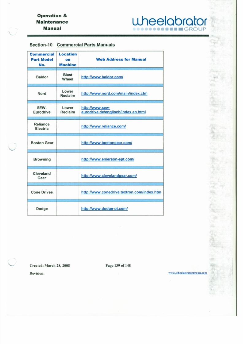
7/30/2019 MANUAL DE USUARIO GRANALLADORA (2).pdf
http://slidepdf.com/reader/full/manual-de-usuario-granalladora-2pdf 151/240
No. Machine
BaldorBlast
http://www.baldor.com/Wheel
NordLower
http://www.nord.com/mainlindex.cfmReclaim
SEW- Lower http://www.sew-
Eurodrive Reclaim eurodrive.de/englisch/index.en.html
Reliancehttp://www.reliance.com/
Electric
Boston Gear http://www.bostongear.com/
Browning http://www.emerson-ept.com/
Operation &
Maintenance
Manualuheelabrator -
O •••• GROUP" - - -
Section-11 Recommend Spare Parts
11-1 Wheel Unit Spare Parts
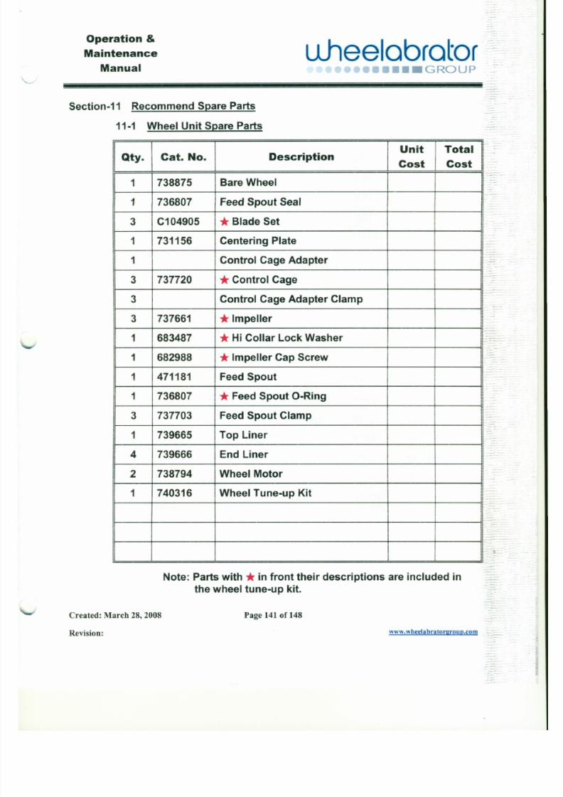
7/30/2019 MANUAL DE USUARIO GRANALLADORA (2).pdf
http://slidepdf.com/reader/full/manual-de-usuario-granalladora-2pdf 152/240
DescriptionUnit Total
Qty. Cat. No.Cost Cost
1 738875 Bare Wheel
1 736807 Feed Spout Seal
3 C104905 *Blade Set
1 731156 Centering Plate
1 Control Cage Adapter
3 737720 *Control Cage
3 Control Cage Adapter Clamp
3 737661 *Impeller1 683487 *Hi Collar Lock Washer
1 682988 *Impeller Cap Screw
1 471181 Feed Spout
::
Operation &Maintenance
Manual
u .hee lab ra to r••• GROUP
- -
11-2 Lower Reclaim Assembly
:: Qty. Cat. No. Description Unit TotalCost Cost
J
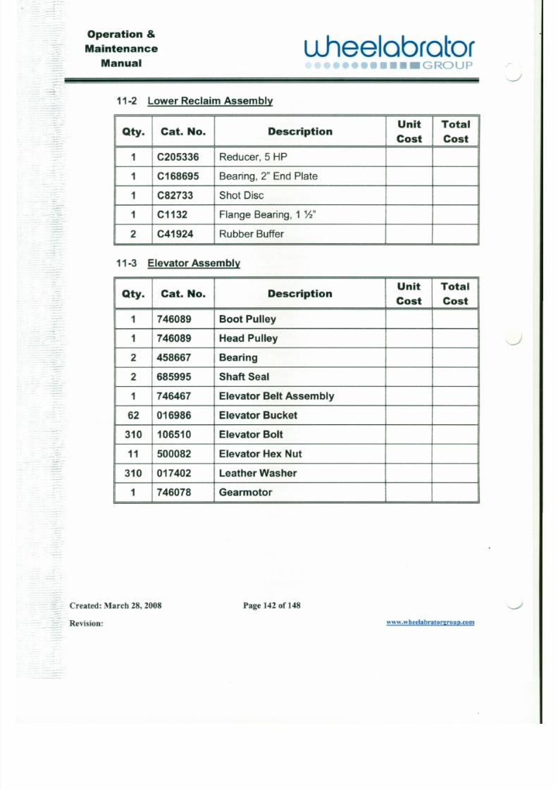
7/30/2019 MANUAL DE USUARIO GRANALLADORA (2).pdf
http://slidepdf.com/reader/full/manual-de-usuario-granalladora-2pdf 153/240
1 C205336 Reducer, 5 HP
1 C168695 Bearing, 2" End Plate
1 C82733 Shot Disc
1C1132 Flange Bearing, 1 ' Y : z "
2 C41924 Rubber Buffer
11-3 Elevator Assembly
r
Qty. Cat. No. DescriptionUnit Total
Cost Cost
1 746089 Boot Pulley
1 746089 Head Pulley
2 458667 Bearing
2 685995 Shaft Seal
J
Operation &
Maintenance
Manualuheelobrotor
•• ("r;n•••• G RO U P" - -
11-4 Upper Reclaim &Separator Assembly
Qty. Cat. No. DescriptionUnit Total
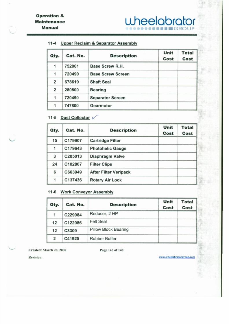
7/30/2019 MANUAL DE USUARIO GRANALLADORA (2).pdf
http://slidepdf.com/reader/full/manual-de-usuario-granalladora-2pdf 154/240
Cost Cost
I752001 Base Screw R.H.
1 720490 Base Screw Screen
2 678619 Shaft Seal
2 280800 Bearing
1 720490 Separator Screen
1 747800 Gearmotor
11-5 Dust Collector V
Qty. Cat. No. Description Unit Total ICost Cost
15 C179907 Cartridge Filter
1 C179643 Photohelic Gauge
- _ . - -_ . Operation &Maintenance
Manualulleelabrator
••• GROUP
-.- ..=::~--: : : : i i i i i i i i i i i i i i i i i i i i ii i i i i i i i i i i i i i i i i i i i ii i i i i i i i i i i i i i i i i i i i ii i i i i i i i i i i i i i i i i i i i ii i i i i i i i i i i i i i i i i i i i i ii i i i i i i i i i i i i i i i i i i i ii i i i i i i i i i i i i i i i i i i i ii i i i i i i i i i i i i i i i i i i i ii i i i i i i i i i i i i i i i i i i i ii i i i i i i i i i i i i i i i i i i i ii i i i i i i i i i i i i i i i i i i i i ii i i i i i i i i i i i i i i i i i i i ii i i i i i i i i i i i i i i i i i i i ii i i i i i i i i i i i i i i i i i i i ii i i i i i i i i i i i i i i i i i i i ii i i i i i i i i i i i i ! ! !i ! ! ! i i i ! ! !i!
11-7 Liners in Line
Qty. Cat. No. DescriptionUnit Total
Cost Cost
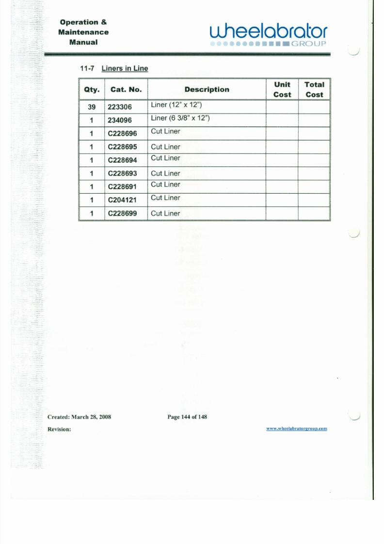
7/30/2019 MANUAL DE USUARIO GRANALLADORA (2).pdf
http://slidepdf.com/reader/full/manual-de-usuario-granalladora-2pdf 155/240
- -
39 223306Liner (12" x 12")
1 234096Liner (6 3/8" x 12")
1 C228696Cut Liner
1 C228695 Cut Liner
1 C228694Cut Liner
1 C228693 Cut Liner
1 C228691 Cut Liner
1 C204121 Cut Liner
1 C228699 Cut Liner•. .:'~.:;,. - ::
-
Operation &
Maintenance
Manual
u .hee lab ra to r•••• GROUP
Section-12 Machine Drawings
12-1 Base Machine
The following drawings, listed in the order of insertion, are considered
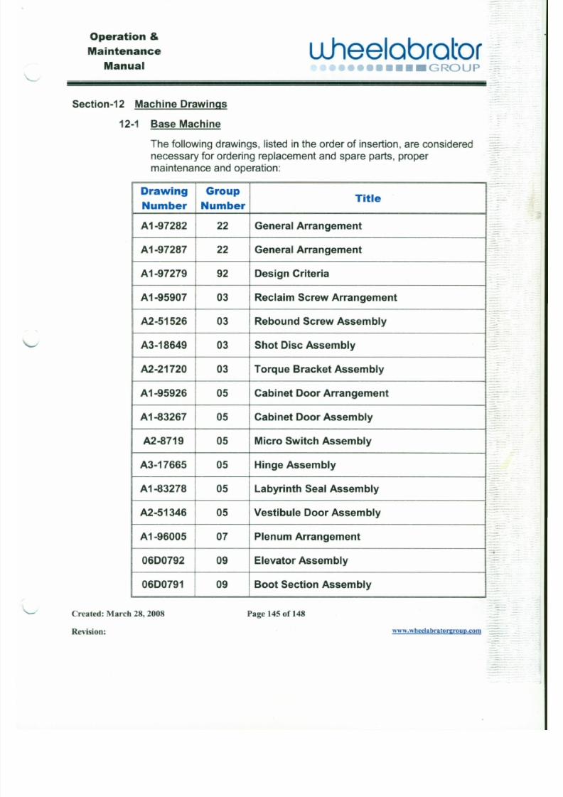
7/30/2019 MANUAL DE USUARIO GRANALLADORA (2).pdf
http://slidepdf.com/reader/full/manual-de-usuario-granalladora-2pdf 156/240
necessary for ordering replacement and spare parts, propermaintenance and operation:
Drawing GroupTitle
Number Number
A1-97282 22 General Arrangement
A1-97287 22 General Arrangement -
A1-97279 92 Design Criteria
A1-95907 03 Reclaim Screw Arrangement
~
A2-51526 03 Rebound Screw Assembly:
A3-18649 03 Shot Disc Assembly
A2-21720 03 Torque Bracket Assembly..
_ .. . -.Operation &Maintenance
Manualu .hee lab ra to r
• : : : J • • G RO U P
c.: : : : :: :~: i i i i i ! i i ! ! i ! ii l i i i i i ! i i ! !i ! i i l i i i i i ! i i! ! i ! i i l i i i i i! i i ! ! i ! i i li i i i i ! i i ! ! i ! i il i i i i i ! i i ! !i ! i i l i i ! i i i i i ii i i i i i i i ! i i i i i i i i i ii i i i ! i i i i i i i i i i i i i i !i i i i i i i i i i i i i i ! i ii i i i i i i i i i i i ! i i i i i ii i i i i i i i ! i i i i i i i i i ii i i i ! i i i i i i i i i i i i i i !i i i i i i i i i i i i i i ! i ii i i i i i i i i i i i ! i i i i i ii i i i i i i i ! i i i i i i i i i ii i i i ! i i i i i i i i i i i i i i !i i i i i i i i i i i i i i ! i ii i i i i i i i i i i i ! i i i i i ii i i i i i ! i i i ! ! i !! !
-
Drawing GroupTitle
Number Number
0600790 09 Head Section Assembly
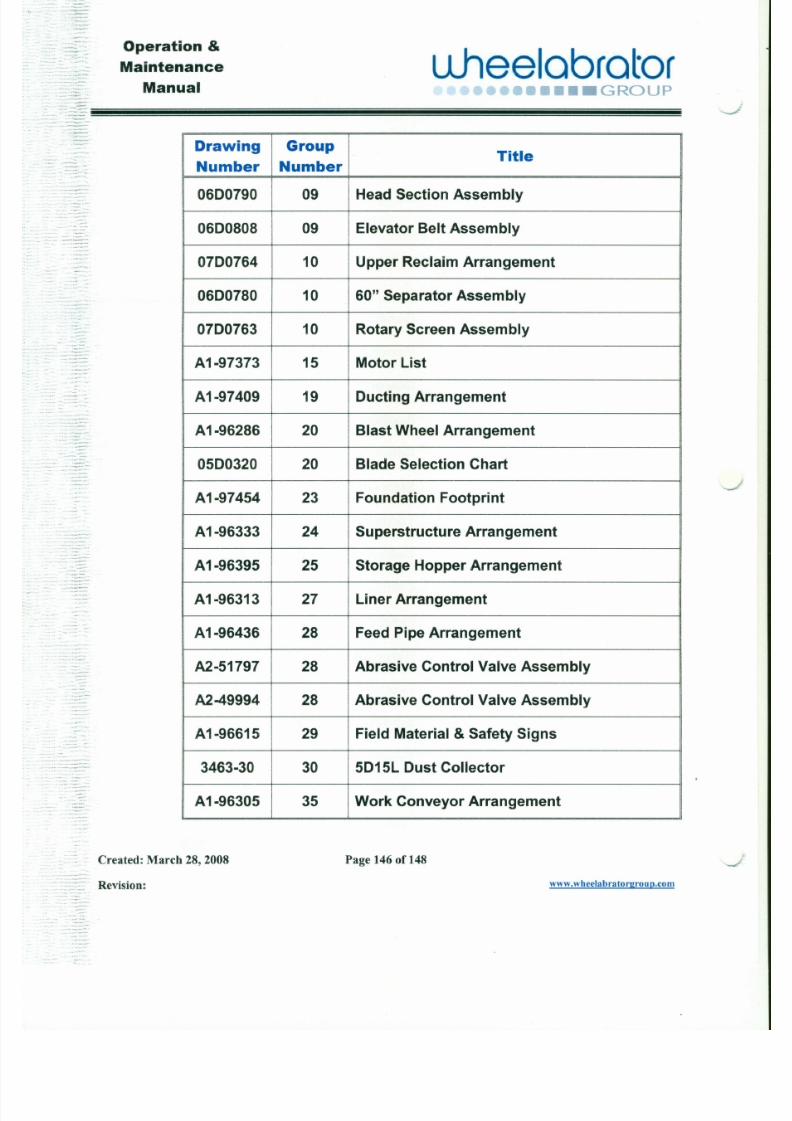
7/30/2019 MANUAL DE USUARIO GRANALLADORA (2).pdf
http://slidepdf.com/reader/full/manual-de-usuario-granalladora-2pdf 157/240
0600808 09 Elevator Belt Assembly
0700764 10 Upper Reclaim Arrangement
0600780 10 60" Separator Assembly
0700763 10 Rotary Screen Assembly
A1-97373 15 Motor List
A1-97409 19 Oucting Arrangement
A1-96286 20 Blast Wheel Arrangement
0500320 20 Blade Selection Chart
A1-97454 23 Foundation Footprint
A1-96333 24 Superstructure Arrangement
.~=~: .. : - : : : :~ :
Operation &Maintenance
Manualuheelcorotor:
.J••••GROUP" - - - -
Drawing GroupTitle
Number Number
A2-49185 35 Torque Bracket Assembly
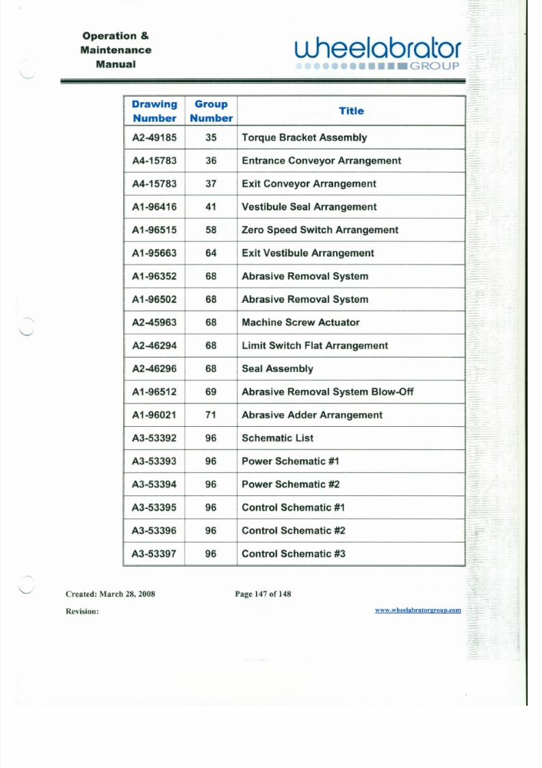
7/30/2019 MANUAL DE USUARIO GRANALLADORA (2).pdf
http://slidepdf.com/reader/full/manual-de-usuario-granalladora-2pdf 158/240
-- -- . . " ,
A4-15783 36 Entrance Conveyor Arrangement
A4-15783 37 Exit Conveyor Arrangement
A1-96416 41 Vestibule Seal Arrangement
A1-96515 58 Zero Speed Switch Arrangement
A1-95663 64 Exit Vestibule Arrangement
A1-96352 68 Abrasive Removal System
A1-96502 68 Abrasive Removal System
A2-45963 68 Machine Screw Actuator
A2-46294 68 Limit Switch Flat Arrangement
A2-46296 68 Seal Assembly
-::::::=='::::~:.'~-.---."
. .. _-- • ..-. - - - - ~ , .. .-.--~- - . . -.. .. . _ ..~ :- -" .. •.::~:
-.~ _ . .._".
Operation &Maintenance
Manualu .hee lab ra to r
••••••••• GROUP.,._ .,
-~~~7.~~'::
Drawing GroupTitle
Number Number
A3-53398 96 Contro l Schemat ic #4
~
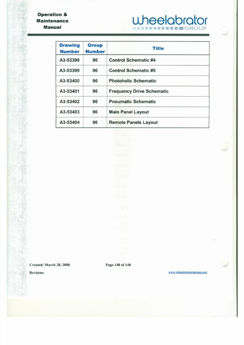
7/30/2019 MANUAL DE USUARIO GRANALLADORA (2).pdf
http://slidepdf.com/reader/full/manual-de-usuario-granalladora-2pdf 159/240
: : : - - : : ~ : : :. : : :
~.. _ .._ , ._ _ .. .
A3-53399 96 Control Schematic #5
A3-53400 96 Photohelic Schematic
A3-53401 96 Frequency Drive Schematic
A3-53402 96 Pneumatic Schematic
A3-53403 96 Main Panel Layout
A3-53404 96 Remote Panels Layout
J
--@NORTHERN Fan Data Sheet CMLN~~~~:,'g~~~~~~~C
BWWER@o Winnipeg, MB. R2C 2Z8Phone: ( 2 0 4 ) 2 2 2 - 4 2 1 6~ ~~~~~~~~ F _ a X _ ( ~2 M_ ) ~2 _ 2 2 _ - 7_0 1
~STOMER: Fox Tech Inc.
SOLD BY: C.B. Airtech Ltd / BobG
TAG:
ORDER #: A56948
CUSTOMER PO: 3463301
LINE ITEM #: 56948.01
Qty 1 Square Fan - BI, Design 7620, Size 2450, Class 2, 90% SISW, Arr 9, Rot CCW, Discharge DB, Mtr Psn Right
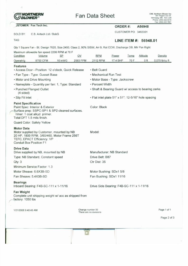
7/30/2019 MANUAL DE USUARIO GRANALLADORA (2).pdf
http://slidepdf.com/reader/full/manual-de-usuario-granalladora-2pdf 160/240
Maximum allowable fan speed 2206 RPM at 70 F
Condition Volume SP OV RPM Power Temp Altitude
Operatin'g 8700 CFM 10inWG 2583 FPM 2112 RPM 17.4 BHP O ft
Density
0.075 Ib/cu ft
Features
•Access Door - Position: 12 o'clock, Quick Release
•FanType - Type: Gusset Base
•Motor and Drive Mounting
•Nameplate - Quantity per fan: 1, Type: Standard
•Punched Flanged Outlet(4sided)
•Slip Fit Inlet
Paint Specification
Paint Spec: Interior & Exteriorurface prep: SSPC-SP1 & SP2 cleaned surfaces.rimer: 1 coat alkyd primer.Total OFT 1.5 mils finish.
Guard Color: Safety Yellow
70 F
•Belt Guard
•Mechanical Run Test•Motor Base - Type: J ackscrew
•Percent Width
•Shaft & Bearing Guard w/ access to bearing zerks
•Flat inlet plate 51" x 51"; 12-5/16" hole spacing
Color: Black
~- - - - - - - - H- - - - - - - - ~
- - - - u- - - - ~i l - - - D- - -
Ir-1
B
E
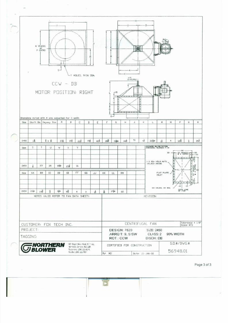
7/30/2019 MANUAL DE USUARIO GRANALLADORA (2).pdf
http://slidepdf.com/reader/full/manual-de-usuario-granalladora-2pdf 161/240
IS J \
~ Y HO LES, 9/ 16 D lA .
f k ~ Y w o . y
CC\J - DB
1
~ ~
/ Qg~1r4lM O T O R P O S I T I O N : R IG H T L r -~ ::; ! J
I.....
"'===1 : "'~ /',v
:/Rti"-----
'Q J', . ,.
FI
DI"enslons noted wl1:h • Q re QdJ ustE'cI for Y o width
SIzE? Sh.ft Diu Keywo..y SIze A B C D E F G H J K L . , N P Q R
r:-'" 2450 Iii ~ X Ii 23~ 19i 22~ 19~ 42i 2BB 11M" 44~
51 42 32/1;- 12 4 12t1;
*262
s T U IN X YD[SCHIIR~ B[ LlU -Ij r,l lnfRN
Size Dtlo£t.r: sml'tA lL TD..[R.-NC:l: I: us
r---AA-DD - n GGSPACE1f -DD
Iii •• CNTRS _cc
NORTHERN BLOWER LUBRICATION INSTRUCTION INDEX ENGLISH
BEARING
DESCRIPTION MFR NB PUBLICATION BEARING SERIES
F4B-DL-000 Dodge
F4B-DL-100 Dodge
F4B-DL-200 Dodge
F4B-SC-000 Dodge
F4B-SC-100 Dodge
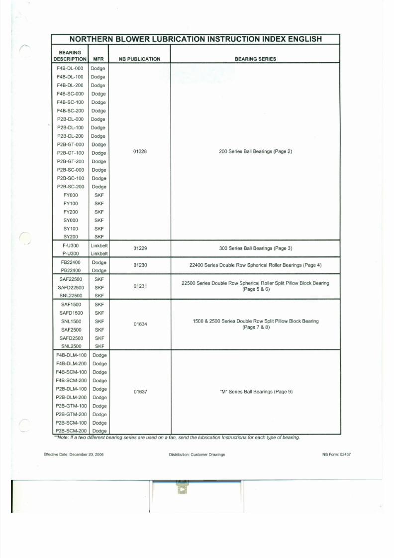
7/30/2019 MANUAL DE USUARIO GRANALLADORA (2).pdf
http://slidepdf.com/reader/full/manual-de-usuario-granalladora-2pdf 162/240
F4B-SC-200 Dodge
P2B-DL-000 Dodge
P2B-DL-100 Dodge
P2B-DL-200 Dodge
P2B-GT-000 Dodge
P2B-GT-100 Dodge 01228 200 Series Ball Bearings (Page 2)
P2B-GT-200 Dodge
P2B-SC-000 Dodge
P2B-SC-100 Dodge
P2B-SC-200 Dodge
FYOOO SKF
FY100 SKF
FY200 SKF
SYOOO SKFSY100 SKF
SY200 SKF
F-U300 Linkbelt01229 300 Series Ball Bearings (Page 3)
P-U300 Linkbelt
FB22400 Dodge01230 22400 Series Double Row Spherical Roller Bearings (Page 4)
@NORTHERNSWWER®
l u b r i c a t i o n I n s t r u c t i o n s200 Series Ball Bearings
Procedure For Applying Lubricant To Bearings
Apply sufficient grease when lubricating to cause some purging of grease at the seals.
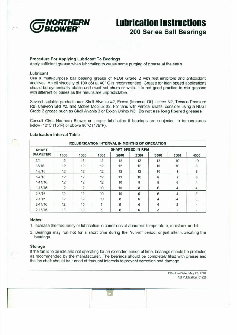
7/30/2019 MANUAL DE USUARIO GRANALLADORA (2).pdf
http://slidepdf.com/reader/full/manual-de-usuario-granalladora-2pdf 163/240
,Lubricant
Use a multi-purpose ball bearing grease of NLGI Grade 2 with rust inhibitors and antioxidantadditives. An oil viscosity of 100 cSt at 40° C is recommended. Grease for high speed applications
should be dynamically stable and must not churn or whip. It is not good practice to mix greases
with different oil bases as the results are unpredictable.
Several suitable products are: Shell Alvania #2, Exxon (Imperial Oil) Unirex N2, Texaco Premium
RB, Chevron SRI #2, and Mobile Mobilux #2. For fans with vertical shafts, consider using a NLGI
Grade 3 grease such as Shell A1vania3 or Exxon Unirex N3. Do not use long fibered greases.
Consult CML Northern Blower on proper lubrication if bearings are subjected to temperatures
below -10°C (15°F) or above 80°C (175°F).
Lubrication Interval Table
RELUBRICATION INTERVAL IN MONTHS OF OPERATION
SHAFT SHAFT SPEED IN RPM
DIAMETER 1000 1500 1800 2000 2500 3000 3500 4000
3/ 4 12 12 12 12 12 12 10 10
r:
@NORTHERNSIDWER®
l u b r i c a t i o n I n s t r u c t i o n s300 Series Ball Bearings
Procedure For Applying Lubricant To Bearings
Apply sufficient grease when lubricating to cause some purging of grease at the seals.
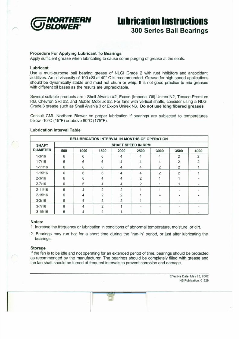
7/30/2019 MANUAL DE USUARIO GRANALLADORA (2).pdf
http://slidepdf.com/reader/full/manual-de-usuario-granalladora-2pdf 164/240
Lubricant
Use a multi-purpose ball bearing grease of NLGI Grade 2 with rust inhibitors and antioxidant'additives. An oil viscosity of 100 cSt at 40° C is recommended. Grease for high speed applications
should be dynamically stable and must not churn or whip. It is not good practice to mix greases
with different oil bases as the results are unpredictable.
Several suitable products are: Shell Alvania #2, Exxon (Imperial Oil) Unirex N2, Texaco PremiumRB, Chevron SRI #2, and Mobile Mobilux #2. For fans with vertical shafts, consider using a NLGIGrade 3 grease such as Shell Alvania 3 or Exxon Unirex N3. Do not use long fibered greases.
Consult CML Northern Blower on proper lubrication if bearings are subjected to temperaturesbelow -10°C (15°F) or above 80°C (175°F).
Lubrication Interval Table
RELUBRICATION INTERVAL IN MONTHS OF OPERATION
SHAFT SHAFT SPEED IN RPM
DIAMETER 500 1000 150 0 2000 2500 3000 3500 4000
1-3/16 6 6 6 4 4 4 2 2
1-7/16 6 6 6 4 4 4 2 2
@NORTHERNBI .DWER®
l u b r i c a t i o n I n s t r u c t i o n s22400 Series Double Row
Spherical Roller Bearings
Procedure For Applying Lubricant To Bearings
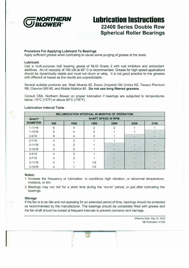
7/30/2019 MANUAL DE USUARIO GRANALLADORA (2).pdf
http://slidepdf.com/reader/full/manual-de-usuario-granalladora-2pdf 165/240
Apply sufficientgreasewhen lubricatingto causesome purgingofgreaseatthe seals.
LubricantUse a multi-purpose ball bearing g-easeof NLGI Grade 2 with rust inhibitors and antioxidantadditives. An oil viscosity of 100cStat40° C is recommended. Grease for high speed applicationsshould be dynamically stable and must not churn or whip. It is not good practice to mix greaseswith differentoil bases as the results are unpredictable.
Several suitable products are: Shell Alvania #2, Exxon (Imperial Oil) UnirexN2, Texaco PremiumRB,ChevronSRI#2, andMobileMobilux#2. Do not use long fibered greases.
Consult CML Northern Blower on proper lubrication if bearings are subjected to temperaturesbelow-10°C (15°F) or above BO °C (176°F).
Lubrication Interval Table
RELUBRICATION INTERVAL IN MONTHS OF OPERATION
SHAFT SHAFT SPEED IN RPM
DIAMETER 500 1000 1500 2000 22 00 2700
1-11/16 6 4 2 2 1 1
@NORTHERNBI.DWER®
This Lubrication Instruction is for 22500series
bearing assemblies utilizing the 22200seriesbearings only.
l u b r i c a t i o n I n s t r u c t i o n sSplit Pillow Block Bearings22500 Series Double Row Spherical
Roller Bearings
Re-pack the pillow block as described above.
Lubricant
Use a multi-purpose ball bearing grease of NLGI
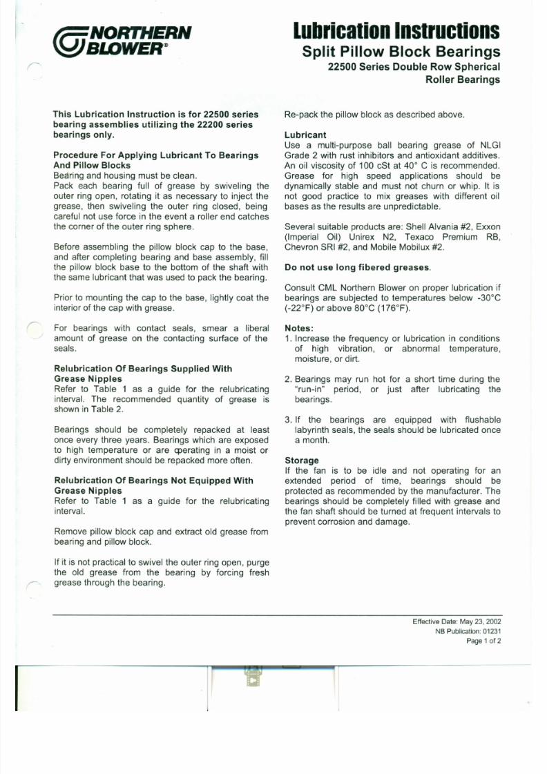
7/30/2019 MANUAL DE USUARIO GRANALLADORA (2).pdf
http://slidepdf.com/reader/full/manual-de-usuario-granalladora-2pdf 166/240
Procedure ForApplying Lubricant To Bearings
And PillowBlocks
Bearing and housing must be clean.Pack each bearing full of grease by swiveling theouter ring open, rotating it as necessary to inject thegrease, then swiveling the outer ring closed, being
careful not use force in the event a roller end catchesthe corner of the outer ring sphere.
Before assembling the pillow block cap to the base,and after completing bearing and base assembly, fillthe pillow block base to the bottom of the shaft withthe same lubricant that was used to pack the bearing.
Prior to mounting the cap to the base, lightly coat the
interior of the cap with grease.
r For bearings with contact seals, smear a liberalamount of grease on the contacting surface of theseals.
Relubrication Of Bearings Supplied With
Grade 2 with rust inhibitors and antioxidant additives.An oil viscosity of 100 cSt at 40° C is recommended.Grease for high speed applications should bedynamically stable and must not churn or whip. It isnot good practice to mix greases with different oilbases as the results are unpredictable.
Several suitable products are: Shell Alvania #2, Exxon(Imperial Oil) Unirex N2, Texaco Premium RB,Chevron SRI #2, and Mobile Mobilux #2.
Do not use long fibered greases.
Consult CML Northern Blower on proper lubrication ifbearings are subjected to temperatures below -30°C
(-22°F) or above so -c (176°F).
Notes:
1. Increase the frequency or lubrication in conditionsof high vibration, or abnormal temperature,moisture, or dirt.
Table 1
RELUBRICAT ION INTERVAL IN H OUR S O F O PER AT IO N
SHAFTDIA . S HA FT S P EE D (rpm)
IN CHES 500 700 900 1200 1400 1600 1800 2000 2200 2400 2600 3000 3600
1 3/ 16 8900 6200 5000 3800 3250 2650 2250 1950 1650 1450 1250 1050 825
1 7 / 16 7500 5300 4300 3000 2650 2050 1750 1500 1250 1150 950 800 580
1 11/ 1 6 7000 5050 4050 2800 2350 1850 1625 1400 1200 1000 900 700 520
1 15 / 1 6 6600 4800 3900 2650 2100 1750 1500 1250 1100 875 800 625 460
2 3/ 16 6100 4500 3500 2250 1850 1500 1300 1100 900 750 600 480 300
2 7 / 16 5800 4350 3250 2050 1650 1400 1150 92 0 725 585 500 350 200
2 11/ 16 5700 4200 3100 1950 1600 1250 975 840 650 550 440 310 150
2 15/ 16 5600 4100 3000 1900 1500 1200 925 775 590 500 400 250
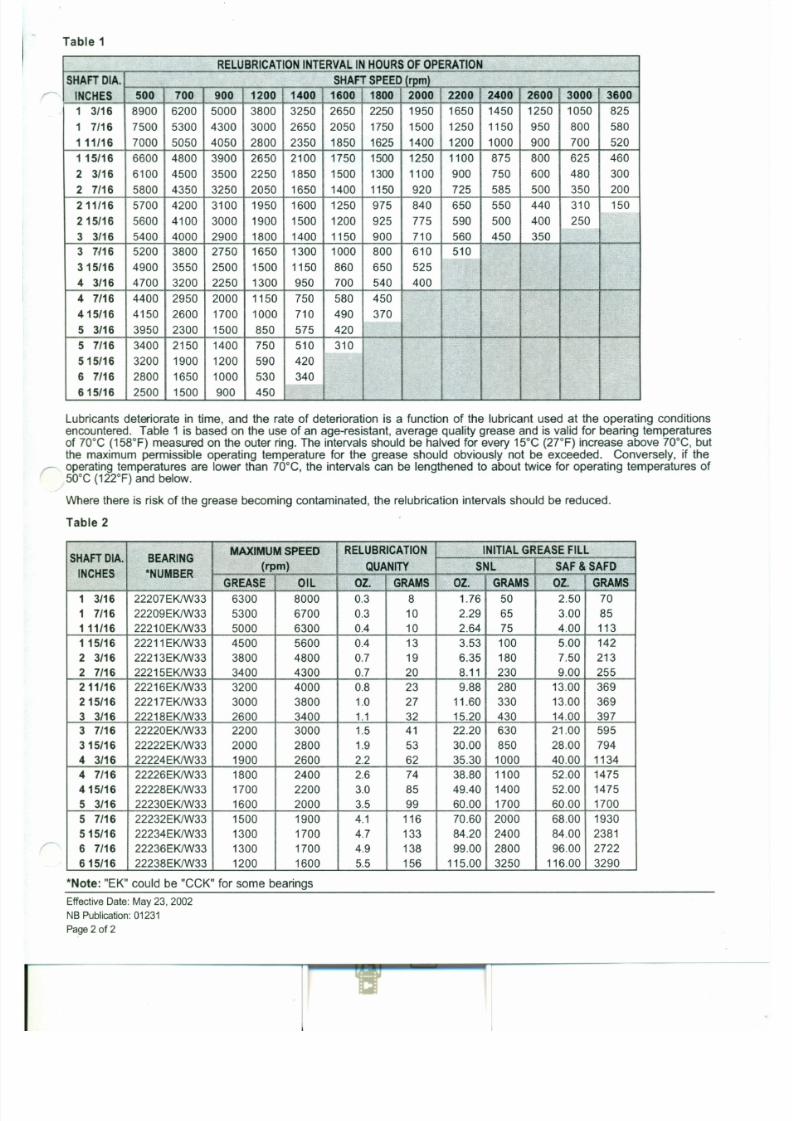
7/30/2019 MANUAL DE USUARIO GRANALLADORA (2).pdf
http://slidepdf.com/reader/full/manual-de-usuario-granalladora-2pdf 167/240
3 3/ 16 5400 4000 2900 1800 1400 1150 90 0 710 560 450 350
3 7 / 16 5200 3800 2750 1650 1300 1000 800 610 510
3 15/ 16 4900 3550 2500 1500 1150 860 650 525
4 3/ 16 4700 3200 2250 1300 950 700 540 400
4 7 / 16 4400 2950 2000 1150 750 580 450
415/ 16 4150 2600 1700 1000 710 490 3705 3/ 16 3950 2300 1500 850 575 420
5 7 / 16 3400 2150 1400 750 510 310
515 / 1 6 3200 1900 1200 590 420
6 7 / 16 2800 1650 1000 530 340
615/ 1 6 2500 1500 90 0 450
Lubricants deteriorate in time, and the rate of deterioration is a function of the lubricant used at the operating conditionsencountered. Table 1 is based on the use of an age-resistant, average quality grease and is valid for bearing temperatures
of 70°C (158°F) measured on the outer ring. The intervals should be halved for every 15°C (2rF) increase above 70°C, butthe maximum permissible operating temperature for the grease should obviously not be exceeded. Conversely, if theoperating temperatures are lower than 70°C, the intervals can be lengthened to about twice for operating temperatures of50°C (122°F) and below.
Where there is risk of the grease becoming contaminated, the relubrication intervals should be reduced.
Table 2
@NORTHERNSWWER®
This Lubrication Instruction is for 1500and
2500series bearing assemblies utilizing the
1200and2200series bearings only.
Procedurefor applying lubricant to bearings
l u b r i c a t i o n I n s t r u c t i o n sSplit Pillow Block Bearings1500 & 2500 Series Double Row Bearings
If it is not practical to swivel the outer ring open,purge the old grease from the bearing by forcing
freshgrease throughthe bearing.
Re-pack the pillowblockas describedabove.
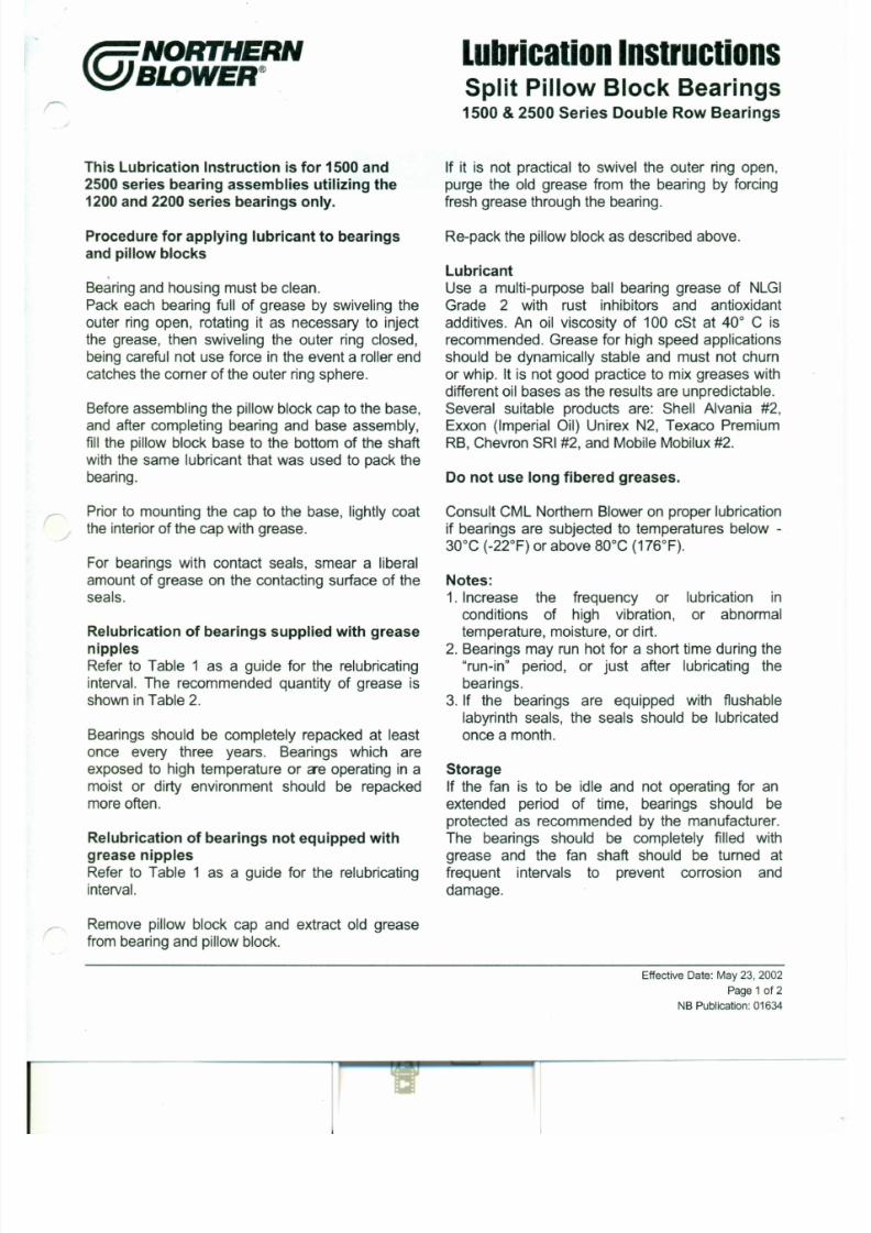
7/30/2019 MANUAL DE USUARIO GRANALLADORA (2).pdf
http://slidepdf.com/reader/full/manual-de-usuario-granalladora-2pdf 168/240
andpillowblocks
.Bearingand housingmustbe clean.Pack each bearing full of grease by swiveling theouter ring open, rotating it as necessary to injectthe grease, then swiveling the outer ring closed,beingcareful not use force in the eventa rollerendcatchesthe corner of the outer ringsphere.
Beforeassembling the pillowblockcap to the base,and after completing bearing and base assembly,fill the pillow block base to the bottomof the shaftwith the same lubricant that was used to packthebearing.
Priorto mounting the cap to the base, lightly coatthe interiorof the capwith grease.
For bearings with contact seals, smear a liberalamountof grease on the contacting surface of the
Lubricant
Use a multi-purpose ball bearing grease of NLGIGrade 2 with rust inhibitors and antioxidantadditives. An oil viscosity of 100 cSt at 40° C isrecommended. Grease for high speed applicationsshould be dynamically stable and must not churnor whip. It is not good practice to mix greases withdifferentoil bases as the results are unpredictable.Several suitable products are: Shell Alvania #2,Exxon (Imperial Oil) Unirex N2, Texaco PremiumRB, ChevronSRI#2, andMobileMobilux#2.
Donotuse long fibered greases.
ConsultCML NorthemBloweron properlubricationif bearings are subjected to temperatures below -30°C (-22°F) orabove BO °C (176°F).
Notes:
Table 1
DOUB LE R OW B ALL B EAR IN G S
SHAFTDIA . SHAF T SP EED (rpm)
INCHES 5 0 0 7 0 0 9 0 0 1 2 0 0 1 4 0 0 1 6 0 0 1 8 0 0 2 0 0 0 2 2 0 0 2 4 0 0 2 6 0 0 3 0 0 0 3 6 0 0
1·3/16 8 7 6 0 8 7 6 0 8 7 6 0 8 7 6 0 8 7 6 0 8 7 6 0 8 7 6 0 8 7 6 0 8 7 6 0 8 7 6 0 8 7 6 0 8 0 0 0 7 0 0 0
1·7/16 8 7 6 0 8 7 6 0 8 7 6 0 8 7 6 0 8 7 6 0 8 7 6 0 8 7 6 0 8 7 6 0 8 7 6 0 8 4 0 0 7 8 0 0 7 0 0 0 5 8 0 0
1 ·11/16 8 7 6 0 8 7 6 0 8 7 6 0 8 7 6 0 8 7 6 0 8 7 6 0 8 7 6 0 8 7 6 0 8 5 0 0 8 0 0 0 7 4 0 0 6 4 5 0 5 0 5 0
1·15/16 8 7 6 0 8 7 6 0 8 7 6 0 8 7 6 0 8 7 6 0 8 7 6 0 8 7 6 0 8 7 6 0 8 2 0 0 7 6 0 0 7 0 0 0 4 5 0 0 3 5 0 0
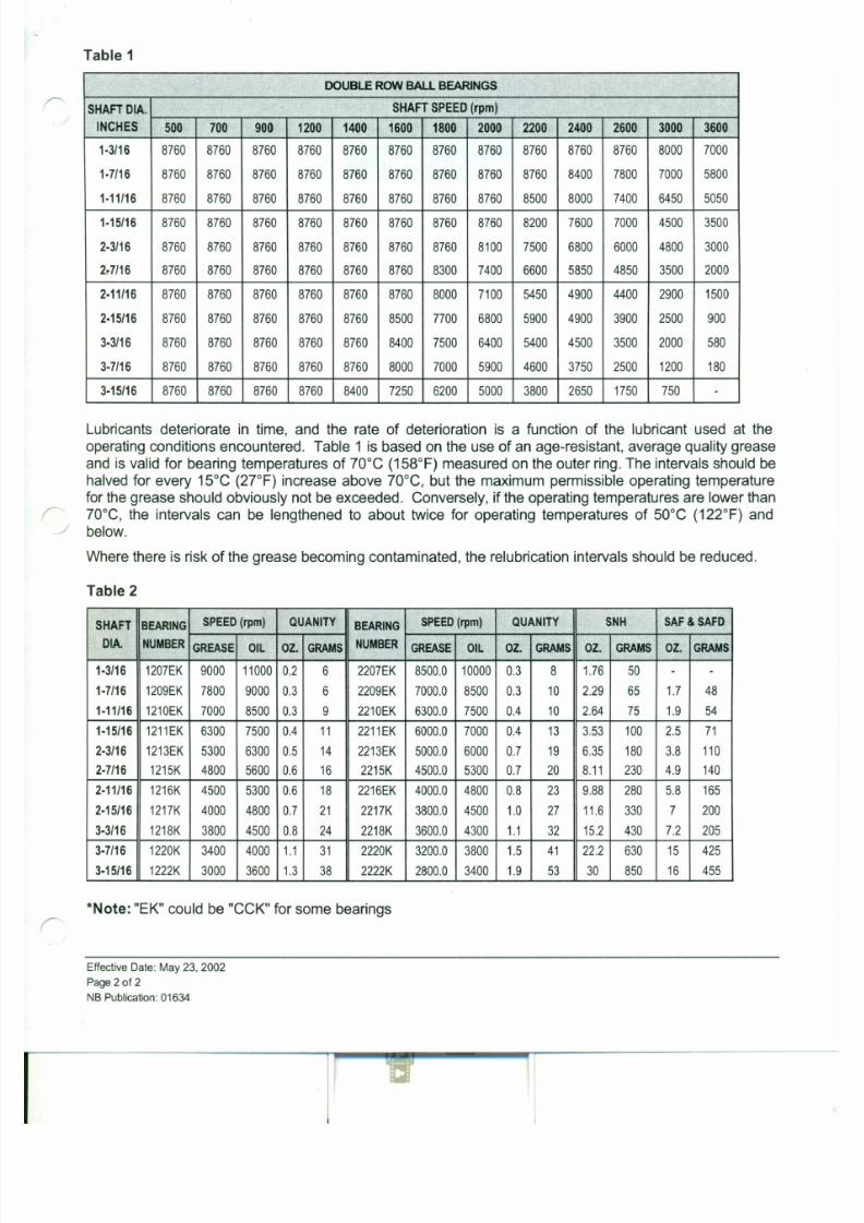
7/30/2019 MANUAL DE USUARIO GRANALLADORA (2).pdf
http://slidepdf.com/reader/full/manual-de-usuario-granalladora-2pdf 169/240
2·3116 8 7 6 0 8 7 6 0 8 7 6 0 8 7 6 0 8 7 6 0 8 7 6 0 8 7 6 0 8 1 0 0 7 5 0 0 6 8 0 0 6 0 0 0 4 8 0 0 3 0 0 0
27/16 8 7 6 0 8 7 6 0 8 7 6 0 8 7 6 0 8 7 6 0 8 7 6 0 8 3 0 0 7 4 0 0 6 6 0 0 5 8 5 0 4 8 5 0 3 5 0 0 2 0 0 0
2·11/16 8 7 6 0 8 7 6 0 8 7 6 0 8 7 6 0 8 7 6 0 8 7 6 0 8 0 0 0 7 1 0 0 5 4 5 0 4 9 0 0 4 4 0 0 2 9 0 0 1 5 0 0
2·15/16 8 7 6 0 8 7 6 0 8 7 6 0 8 7 6 0 8 7 6 0 8 5 0 0 7 7 0 0 6 8 0 0 5 9 0 0 4 9 0 0 3 9 0 0 2 5 0 0 9 0 0
3·3116 8 7 6 0 8 7 6 0 8 7 6 0 8 7 6 0 8 7 6 0 8 4 0 0 7 5 0 0 6 4 0 0 5 4 0 0 4 5 0 0 3 5 0 0 2 0 0 0 5 8 0
3·7/16 8 7 6 0 8 7 6 0 8 7 6 0 8 7 6 0 8 7 6 0 8 0 0 0 7 0 0 0 5 9 0 0 4 6 0 0 3 7 5 0 2 5 0 0 1 2 0 0 1 8 0
3·15/16 8 7 6 0 8 7 6 0 8 7 6 0 8 7 6 0 8 4 0 0 7 2 5 0 6 2 0 0 5 0 0 0 3 8 0 0 2 6 5 0 1 7 5 0 7 5 0 .
Lubricants deteriorate in time, and the rate of deterioration is a function of the lubricant used at the
operating conditions encountered. Table 1 is based on the use of an age-resistant, average quality grease
and is valid for bearing temperatures of 70°C (158°F) measured on the outer ring. The intervals should be
halved for every 15°C (2rF) increase above 70°C, but the maximum permissible operating temperature
for the grease should obviously not be exceeded. Conversely, if the operating temperatures are lower than
/" 70°C, the intervals can be lengthened to about twice for operating temperatures of 50°C (122°F) and~ below.
Where there is risk of the grease becoming contaminated, the relubrication intervals should be reduced.
@NORTHERNBI.DWER® l u b r i c a t i o n G u id e" M " Se r i e s B a l l B e a r i n g s
Dodge SeM, SKF SYM & FYM
Procedure For Applying Lubricant To BearingsApply sufficient grease when lubricating to cause some purging of grease at the seals.

7/30/2019 MANUAL DE USUARIO GRANALLADORA (2).pdf
http://slidepdf.com/reader/full/manual-de-usuario-granalladora-2pdf 170/240
Lubricant
. Use a multi-purpose ball bearing grease of NLGI Grade 2 with rust inhibitors and antioxidant
additives. An oil viscosity of 100 cSt at 40°C is recommended. Grease for high speed applications
should be dynamically stable and must not churn or ship. It is not good practice to mix grease with
different oil bases as the results are unpredictable.
Several suitable products are: Shell Alvania #2, Exxon (Imperial Oil) Unirex N2. Texaco Premium
RB, Chevron SRI #2, and Mobile Mobilux #2. For fans with vertical shafts, consider using a NLGI
Grade 3 grease such as Shell Alvania 3 or Exxon Unirex N3. Do not use long fibered greases.
Consult CML Northern Blower on proper lubrication if bearings are subjected to temperatures
below -10°C (15°F) or above 80°C (176°F)
Lubricat ion Interval Table
r: RELUBRICATION INTERVAL IN MONTHS OF OPERATION
SHAFT SHAFT SPEED IN RPM
DIAMETER 1000 1500 1800 2000 2500 3000 3500 4000
1-3/16 12 12 12 12 10 8 8 6
F A N E Q U I P M E N TO P E R A T I O N
M A N U A L
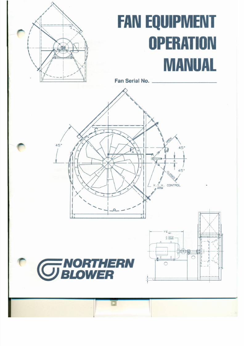
7/30/2019 MANUAL DE USUARIO GRANALLADORA (2).pdf
http://slidepdf.com/reader/full/manual-de-usuario-granalladora-2pdf 171/240
Fan Ser ial No. _
L
T A B L E O F C O N T E N T S
STANDARD TERMS AND CONDITIONS and WARRANTy 4
Standard Terms and Conditions 4
Warranty 5
OPERATION MANUAL - FAN EQUIPMENT 6
7/30/2019 MANUAL DE USUARIO GRANALLADORA (2).pdf
http://slidepdf.com/reader/full/manual-de-usuario-granalladora-2pdf 172/240
SAFETY PRECAUTIONS 6
INSTALLATION, OPERATION & MAINTENANCE
OF CML NORTHERN BLOWER FAN EQUIPMENT 7
Introduction 7
Shipment & Receiving 7
Handling 7
Storage 8
Installation of Fan Equipment.. 8
V-Belt Drive Installation 9
Operation of Fan Equipment 10
Maintenance of Fan Equipment 11
C M L N O R T H E R N B L O W E R I N C .
S T A N D A R D T E R M S A N D C O N D I T I O N S a n d W A R R A N T Y
STANDARD TERMS AND CONDITIONS
TERMS OF PAYMENT: Terms of payment are net thirty (30) days
subject to the prior approval of the CML Northern Blower Inc. ("CML
Northern") Credit Department. Notwithstanding such approval, if in
CML Northern's judgement the customer's financial condition does
notwarrant the continuation ofproduction orshipment onthe original
FREIGHT CLAIMS: Unless otherwise expressly agreed inwriting,
delivery of the product is made FOB CML Northern Plant. The
liability and responsibility of CML Northern for the product ceases
upon delivery of the product ingood order to the carrier. All claims
for damage and shortage in transit are the customer's respon-
sibility and the customer must file the claim against the carrier.
7/30/2019 MANUAL DE USUARIO GRANALLADORA (2).pdf
http://slidepdf.com/reader/full/manual-de-usuario-granalladora-2pdf 173/240
terms, CML Northern reserves the right to request payment in
~dvance. Overdue accounts will bear interest atthe prevailing bank
rate charged to CML Northern.
ACCEPTANCE AND PRICES: Prices quoted for products manu-
factured by CML Northern are subject to acceptance by the pur-
chaser no later than thirty (30) days from the date of the Quotation -
Proposal.
Prices quoted for items which are notmanufactured byCML Northern
such asmotors and drives, etc. are subject to change atany time the
cost of such items charged to CML Northern changes.
Prices onorders for products manufactured byCML Northern are firm
provided approval and release for production and shipment is re-
ceived from the customer within ninety (90) days of the date of CML
Northern's receipt of the customer's order and the products are
shipped within twelve (12) months of the date of CML Northern's
receipt of the customer's order. When such approval and release for
production and shipment is received after ninety (90) days ofthe date
of CML Northern's receipt of the customer's order or products are
shipped after twelve (12) months of the date of CML Northern's
Claims for factory shortage will not be recognized unless such
alleged shortage is reported to CML Northern inwriting within ten
(10) days after receipt of the product.
TAXES: The amount ofany present or future taxes shall be added
to the price contained herein and shall be paid by the customer in
the same manner and with the same effect as if originally added
thereto.
DELAYS: CML Northern shall notbe liable to the customer orto any
third party for anydelays caused by riots, strikes,lockouts, weather,
fire, floods, lack of transportation, accidents, the failure of CML
Northern's suppliers to meet their contractual obligations, break-
downs, or any other contingency beyond CML Northern's reason-
able control and receipt of the product by the customer shall
constitute a waiver of all claims for loss or damage due to delay.
PRODUCT CHANGES: CML Northern reserves the right to
change or modify the product in the interest of continuous product
improvement without liability.
WARRANTY
CML Northern Blower Inc. (the "Seller") warrants products of its
manufacture (the "product", "equipment" or "fan") to be free of
defects inmaterial and workmanship ifproperly installed, and cared
for, and operated under normal conditions, and with competent
supervision, all in accordance with the Seller's Operation Manual.
If any questions exist as to whether the proposed operation of the
Seller's equipment iswithin "normal conditions" for such equipment,
details ofsuch proposed operation should beprovided to the Sellerat its Winnipeg factory. The Seller will review the proposed opera-
tion ofthe equipment (at a fee) and advise ifthe proposed operation
is acceptable.
(5) The performance of the Seller's fan equipment outside of the
laboratory may vary widely and differ from the performance
specifications contained in its sales literature. Therefore, the
Seller cannot and does not guarantee orwarrant the perform-
ance of its fan equipment at the Purchaser's location.
(6) ALL WARRANTIES OF THE SELLER, EXPRESS OR IM-
PLIED, WITH RESPECT TO MOTORS, SWITCHES, CON-
TROLSOR OTHER ACCESSORIES NOT MANUFACTUREDBY THE SELLER, INCLUDING WARRANTIES OF MER-
CHANTABILITY, QUALITY OR FITNESS FOR ANY PAR-
TICULAR PURPOSE, ARE HEREBY EXCLUDED.
7/30/2019 MANUAL DE USUARIO GRANALLADORA (2).pdf
http://slidepdf.com/reader/full/manual-de-usuario-granalladora-2pdf 174/240
(1) The Seller's obligation under this warranty is limited to the
repair or replacement, at its option at its Winnipeg factory, of
any defective part orparts which shall within one (1) year after
shipment thereof to the original purchaser (the "Purchaser"),
be returned to itsWinnipeg factory with transportation chargesprepaid bythe Purchaser and upon such repair or replacement
the Seller shall have fulfilled all its obligations to the Purchaser.
The Seller will notbe liable, inany circumstances, for costs or
expenses incurred by the Purchaser or any person claiming
through the Purchaser in the removal or replacement of
equipment alleged to be defective. Except as specifically
provided herein, the Seller will not be liable, in any circum-
stances, for any loss or damage of whatever nature or kind
(including, without limiting the generality of the foregoing,direct, indirect, incidental or consequential loss ordamage or
damage resulting frombusiness interruption) should the equip-
ment be so defective as to preclude the remedy ofwarranted
defects by repair or replacement. In such event, the Pur-
chaser's sole and exclusive remedy shall be the refund of the
purchase price paid by the Purchaser for all the defective
(7) The Seller shall have no liability under the terms of this
Warranty or otherwise where the Purchaser undertakes the
responsibility of mounting the fan wheel directly to the motor
orturbine shafts withoutthe Seller having inspected and tested
the assembled unit (at a fee) before the fan isoperated inanyfashion. Ifthe Seller does not inspect and test the assembled
unit within ten (10) days of being requested to do so by the
Purchaser and receipt ofpayment of the aforementioned fee,
the Seller shall be deemed to have waived its requirement to
inspect and test the assembled unit.
(8) The Seller shall have no liability under the terms of this
warranty or otherwise until the Purchaser has made full
payment totheSeller forthe product orequipment to which this
warranty is to apply.
(9) NOWARRANTIES WHATSOEVER, EXPRESS OR IMPLIED,
INCLUDING WARRANTIES OF MERCHANTABILITY,
QUALITY OR FITNESS FOR ANY PARTICULAR PUR-
POSE, ARE MADE BY THE SELLER EXCEPT AS EX-
The user should make all personnel who operate or main-
tain the fan equipment aware of all possible hazards.
C M L N O R T H E R N B L O W E R I N C .O P E R A T I O N M A N U A L - F A N E Q U I P M E N T
SAFETY PRECAUTIONS
FAN EQUIPMENT CAN BECOME A SOURCE OF
INJURY AND DEATH IF NOT PROPERLY INSTALLED,
OPERATED OR MAINTAINED. Do not exceed the
maximum operating temperature or speed limits for which
the fan equipment was designed. Limits for some lines of
fan equipment are given inCML Northern Blower Inc. ("CML
THE RESPONSIBILITY FOR PROVIDING SAFETY
ACCESSORIES FOR FAN EQUIPMENT SUPPLIED BY
CML NORTHERN IS THAT OF THE USER OF THE FAN
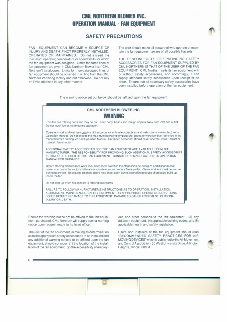
7/30/2019 MANUAL DE USUARIO GRANALLADORA (2).pdf
http://slidepdf.com/reader/full/manual-de-usuario-granalladora-2pdf 175/240
Northern") catalogues. Limits for non-catalogued lines of
fan equipment should be obtained in writing from the CML
Northern Winnipeg factory and not otherwise. Do not rely
on limits obtained in any other manner.
EQUIPMENT. CML Northern sells its fan equipment with
or without safety accessories, and accordingly, it can
supply standard safety accessories upon receipt of an
order. Ensure that all necessary safety accessories have
been installed before operation of the fan equipment.
The warning notice set out below should be affixed upon the fan equipment:
CML NORTHERN BLOWER INC.
W A R N I N GThis fan has rotating parts and may be hot. Keep body, hands and foreign objects away from inlet and outlet.
Do not touch fan or motor during operation.
Operate, install and maintain Q D J ¥ in strict accordance with safety practices and instructions in manufacturer's
Operation Manual. Do not exceed the maximum operating temperature, speed,or vibration level identified in the
manufacturer's catalogues and Operation Manual. Untrained personnel should never operate, install, adjust or
maintain fan or motor.
ADDITIONAL SAFETY ACCESSORIES FOR THE FAN EQUIPMENT ARE AVAILABLE FROM THE
MANUFACTURER. THE RESPONSIBILITY FOR PROVIDING SUCH ADDITIONAL SAFETY ACCESSORIES
INSTALLATION, OPERATION & MAINTENANCEOF CML NORTHERN FAN EQUIPMENT
INTRODUCTION
The purpose of this section is to aid in the proper installa-
tion, operation, and maintenance of CML Northern fan
equipment. These instructions are intended to supplement
good general practices and are not intended to cover
detailed instruction procedures.
The receipt, handling, installation, operation and mainte-
nance of CML Northern fan equipment is the responsibility
of the user. It is important that the installation and start-up
Centr ifugal fans are best lifted using straps attached to
structural base members of the fan. DO NOT LIFT
CENTRIFUGAL FANS BY THE FAN SHAFT, IMPELLER,
FLANGES OR INLET SUPPORTS.
Roof venti lators should be lifted by using straps attached
to lifting lugs or base only. Spreader bars should also be
used to avoid damage to the butterfly damper assembly or
the weatherhood. DO NOT LIFT ROOF VENTILATORS
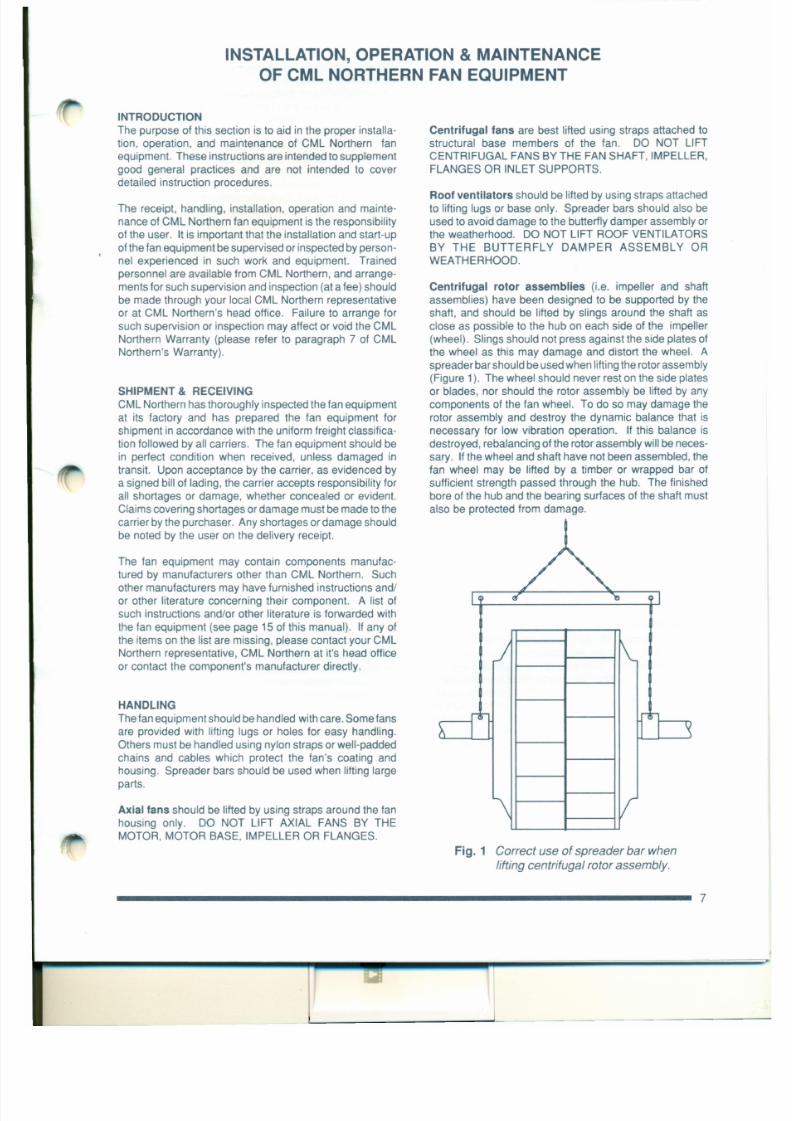
7/30/2019 MANUAL DE USUARIO GRANALLADORA (2).pdf
http://slidepdf.com/reader/full/manual-de-usuario-granalladora-2pdf 176/240
of the fan equipment be supervised or inspected by person-
nel experienced in such work and equipment. Trained
personnel are available from CML Northern, and arrange-
ments for such supervision and inspection (at a fee) should
be made through your local CML Northern representative
or at CML Northern's head office. Failure to arrange for
such supervision or inspection may affect or void the CML
Northern Warranty (please refer to paragraph 7 of CML
Northern's Warranty).
SHIPMENT & RECEIVING
CML Northern has thoroughly inspected the fan equipment
at its factory and has prepared the fan equipment for
shipment in accordance with the uniform freight classifica-
tion followed by all carriers. The fan equipment should be
in perfect condition when received, unless damaged in
transit. Upon acceptance by the carrier, as evidenced by
a signed bill of lading, the carrier accepts responsibility for
all shortages or damage, whether concealed or evident.
Claims covering shortages or damage must be made to the
carrier by the purchaser. Any shortages or damage should
be noted by the user on the delivery receipt.
BY THE BUTTERFLY DAMPER ASSEMBLY OR
WEATHERHOOD.
Cen tr if ugal r otor assembl ies (i.e. impeller and shaft
assemblies) have been designed to be supported by the
shaft, and should be lifted by slings around the shaft as
close as possible to the hub on each side of the impeller
(wheel). Slings should not press against the side plates of
the wheel as this may damage and distort the wheel. A
spreader bar should be used when lifting the rotor assembly
(Figure 1). The wheel should never rest on the side plates
or blades, nor should the rotor assembly be lifted by any
components of the fan wheel. To do so may damage the
rotor assembly and destroy the dynamic balance that is
necessary for low vibration operation. If this balance is
destroyed, rebalancing of the rotor assembly will be neces-
sary. Ifthe wheel and shaft have not been assembled, the
fan wheel may be lifted by a timber or wrapped bar of
sufficient strength passed through the hub. The finished
bore of the hub and the bearing surfaces of the shaft must
also be protected from damage.
(4) Ducts must be independently supported, and must
never be supported by the fan. Use flexible duct
connections wherever possible. The independent
mounting of stacks and ducts to the fan will ensure
that the fan will not be twisted or deformed with the
addition of external loads.
(5) It is recommended that access doors be placed in
ductwork just ahead of the fan inlet and just behind
the fan outlet for ease of inspection and mainte-
nance. IN ORDER TO AVOID EQUIPMENT DAM-
AGE AND PERSONAL INJURY ACCESS DOORS
IN A DUCT SYSTEM SHOULD BE SECURELY
CLOSED AND SHOULD NEVER BE OPENED WITH
lei
L L
A B
1) Dimensions 'A' & '8'
must be measured at
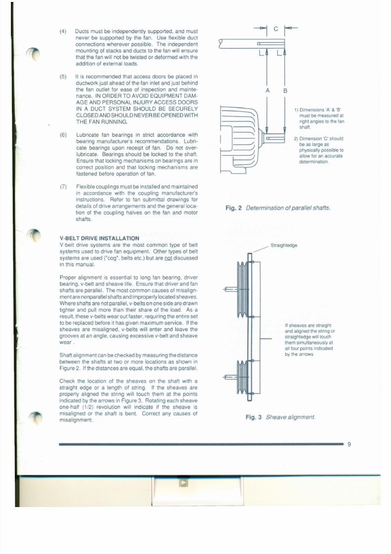
7/30/2019 MANUAL DE USUARIO GRANALLADORA (2).pdf
http://slidepdf.com/reader/full/manual-de-usuario-granalladora-2pdf 177/240
THE FAN RUNNING.
(6) Lubricate fan bearings in strict accordance with
bearing manufacturer's recommendations. Lubri-
cate bearings upon receipt of fan. Do not over-
lubricate. Bearings should be locked to the shaft.
Ensure that locking mechanisms on bearings are in
correct position and that locking mechanisms are
fastened before operation of fan.
(7) Flexible couplings must be installed and maintained
in accordance with the coupling manufacturer's
instructions. Refer to fan submittal drawings for
details of drive arrangements and the generalloca-
tion of the coupling halves on the fan and motor
shafts.
V-BELT DRIVE INSTALLATION
V-belt drive systems are the most common type of belt
systems used to drive fan equipment. Other types of belt
systems are used ("cog", belts etc.) but are ne t discussedin this manual.
"'~'\ u
I- ,
I I/
))
~
~
right angles to the fan
shaft.
2) Dimension 'C' should
be as large as
physically possible to
allow for an accuratedetermination.
Fig. 2 Determination of parallel shafts.
_____ Straightedge
" : : : : : - - j A ---=-=- - - - . . ; , . - -:::::-- - - -- -- - - : :: : -
/ TooTight
--........--==---~ --.--
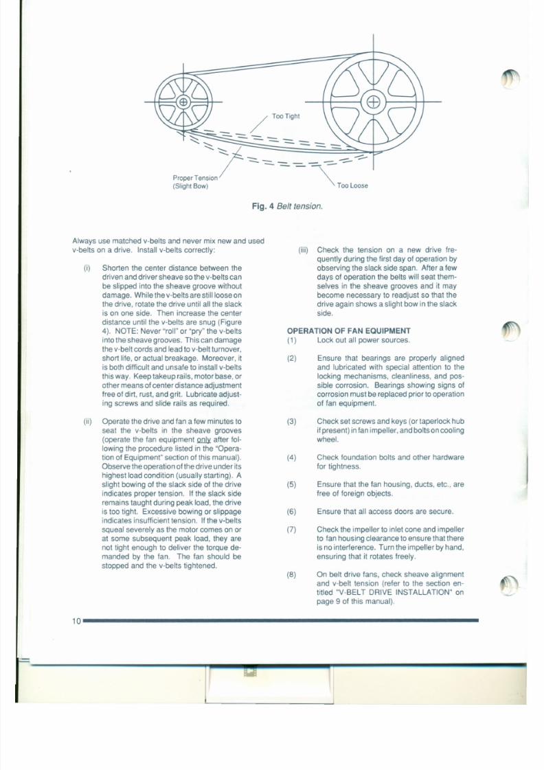
7/30/2019 MANUAL DE USUARIO GRANALLADORA (2).pdf
http://slidepdf.com/reader/full/manual-de-usuario-granalladora-2pdf 178/240
Proper Tension - - - = - - ~(Slight Bow) Too Loose
Fig. 4 Belt tension.
Always use matched v-belts and never mix new and used
v-belts on a drive. Install v-belts correctly:
(i) Shorten the center distance between the
driven and driver sheave so the v-belts can
be slipped into the sheave groove without
damage. While the v-belts are still loose on
the drive, rotate the drive until all the slack
is on one side. Then increase the center
distance until the v-belts are snug (Figure
4). NOTE: Never "roll" or "pry" the v-belts
into the sheave grooves. This can damage
the v-belt cords and lead to v-belt turnover,
short life, or actual breakage. Moreover, it
is both difficult and unsafe to install v-belts
(iii) Check the tension on a new drive fre-
quently during the first day of operation by
observing the slack side span. After a few
days of operation the belts will seat them-
selves in the sheave grooves and it may
become necessary to readjust so that the
drive again shows a slight bow in the slack
side.
OPERATION OF FAN EQUIPMENT
(1) Lock out all power sources.
(2) Ensure that bearings are properly aligned
and lubricated with special attention to the
(9)
(10)
Ifthe fan is equipped with damper or variable
inlet vane, close same to lessen starting load
on motor. Ensure any dampers or variable
inlet vanes furnished with the fan, or used in
conjunction with the fan, do not stick or bind.
Ifan automatic control mechanism is used to
operate the damper or variable inlet vane,
adjust the limits of travel of the automatic
control mechanism in accordance with the
control manufacturer's instructions to avoid
putting force on the damper or variable inlet
vane when it is fully opened or fully closed.
If the fan is driven by an electric motor, read
instructions of motor and starter manufac-
(15) Apply power to the driver momentarily (i.e.
"bump") to check for proper rotation. Any
dampers or other air control devices in the
system should be at least partially closed
during starting periods to reduce power re-
quirements. Damper closure is particularly
important in the case of a fan designed for
high temperature operation being "run in" at
a temperature less than design temperature.
(16) Apply power to the driver and allow the fan to
come up to design speed. Turn off. Look and
listen for any unusual noise or mechanical
action while the impeller isstill spinning. Ifany

7/30/2019 MANUAL DE USUARIO GRANALLADORA (2).pdf
http://slidepdf.com/reader/full/manual-de-usuario-granalladora-2pdf 179/240
(11)
(12)
turer. Ensure that the motor and starter are
set up in compliance with the motor and
starter manufacturers' instructions prior to
any application of electric power. Ifthe fan is
powered by some other form of driver, read
the manufacturer's instructions prior start-
up.
If the fan is equipped with water cooled
bearings turn on the water supply to the
bearings prior to starting the fan. Consult the
water cooled bearing manufacturer's instruc-
tions.
If the fan is to handle a "hot gas" (i.e. a gas
with a temperature greater than 150°F [65°C))
itis imperative that the fan be subject to only
a slow gradual rate of gas temperature
change, not to exceed a rate of 15°F/minute
(8°C/minute). When the fan is being Q l.!1J !l
operation the temperature of the gas must
D .. Q 1 rise at a rate greater than 15°F/minute
(8°C/minute). ~ subject a "cold" fan to a
are noticed, lock out all power sources, locate
cause and correct.
(17) Lock out all power sources and recheck
tightness of all set screws, keys, foundation
bolts and any other hardware. The initial start
up will tend to relieve their tightness and they
may require re-tightening.
(18) Reconnect all power sources.
(19) It is recommended that upon fan installation,
the operating vibration levels be checked to
ensure that the levels do not exceed the
levels indicated on the inspection sheets
shipped with the fan and/or the vibration
levels set forth in the "Vibration" section of
this manual.
Once it has been determined that the fan equipment is
operating satisfactorily, it should be operated, if practical,
for at least eight (8) continuous hours. Operation should be
monitored at least once each hour during this period.
MANUFACTURER'S INSTRUCTIONS TO DETERMINETHE TYPE AND FREQUENCY OF BEARING LUBRICA-
TION REQUIRED.
THE MOTOR BEARINGS SHOULD BE LUBRICATED IN
ACCORDANCE WITH MOTOR MANUFACTURER'S LU-
BRICATION INSTRUCTIONS AND RECOMMENDATIONS
SHOULD BE FOLLOWED CLOSELY.
Bearing failure may be caused by failure to lubricate as
often as required, use of an excessive quantity of lubricantor the use of incompatible lubricants. Excessive vibration,
especially if the bearing is not rotating, will also cause
bearings to fail. Bearings must also be protected from
Periodic checks of voltage, frequency and current of a
motor while in operation are recommended. Such checks
ensure the correctness of frequency and voltage applied to
the motor and yield an indication of the fan load. Compari-
son of this data with previous data will give an indication of
the fan performance. Any serious deviations should be
investigated and corrected.
Spare Parts
Spare parts may be ordered through your CML Northernsales office by providing the following information:
(1) Part name (e.g. impeller, shaft, motor, bear-
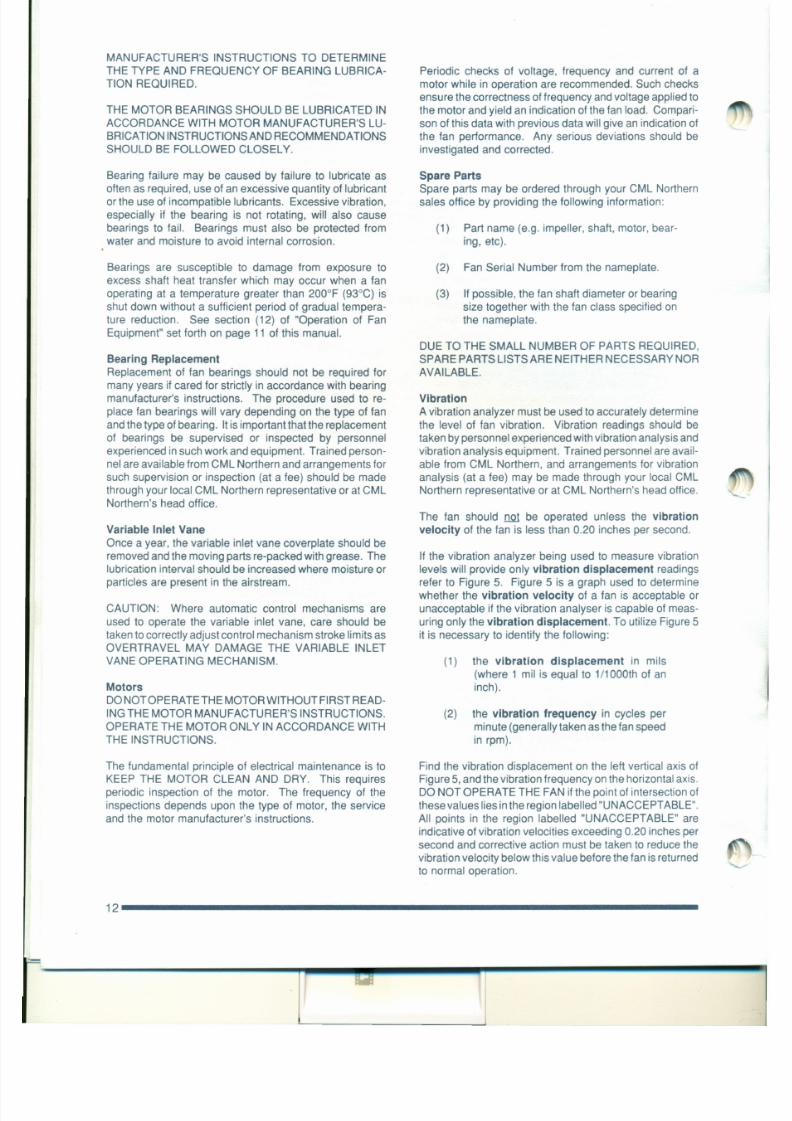
7/30/2019 MANUAL DE USUARIO GRANALLADORA (2).pdf
http://slidepdf.com/reader/full/manual-de-usuario-granalladora-2pdf 180/240
water and moisture to avoid internal corrosion.
Bearings are susceptible to damage from exposure to
excess shaft heat transfer which may occur when a fan
operating at a temperature greater than 200°F (93°C) is
shut down without a sufficient period of gradual tempera-
ture reduction. See section (12) of "Operation of FanEquipment" set forth on page 11 of this manual.
Bearing Replacement
Replacement of fan bearings should not be required for
many years if cared for strictly in accordance with bearing
manufacturer's instructions. The procedure used to re-
place fan bearings will vary depending on the type of fan
and the type of bearing. It is important that the replacement
of bearings be supervised or inspected by personnel
experienced in such work and equipment. Trained person-nel are available from CML Northern and arrangements for
such supervision or inspection (at a fee) should be made
through your local CML Northern representative or atCML
Northern's head office.
Var iab le In let Vane
ing, etc).
(2) Fan Serial Number from the nameplate.
(3) If possible, the fan shaft diameter or bearing
size together with the fan class specified on
the nameplate.
DUE TO THE SMALL NUMBER OF PARTS REQUIRED,
SPARE PARTS LISTS ARE NEITHER NECESSARY NOR
AVAILABLE.
Vibration
A vibration analyzer must be used to accurately determine
the level of fan vibration. Vibration readings should be
taken by personnel experienced with vibration analysis and
vibration analysis equipment. Trained personnel are avail-able from CML Northern, and arrangements for vibration
analysis (at a fee) may be made through your local CML
Northern representative or at CML Northern's head office.
The fan should I lQ1 be operated unless the vibration
velocity of the fan is less than 0.20 inches per second.
6050
40
30
ooC')
oo 0 0o0 0e x ) e n
ooioC\I
ootoC')
oooC')
ooC\I
ooio
o0o0e x ) 0
C\I
oo. " .
ooio
o 0o 0to f'.
«Values are for filtered LU
n,readings taken on the ,fan bearing caps. o
LUC J )'<
Z
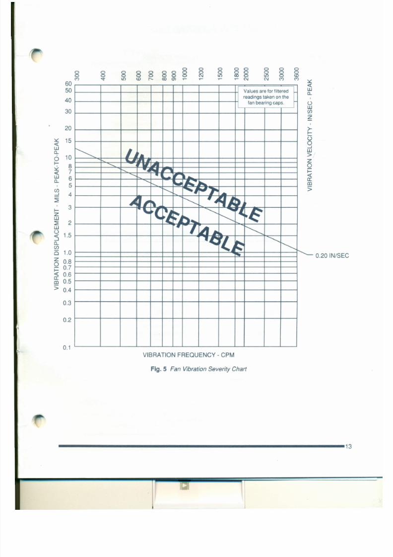
7/30/2019 MANUAL DE USUARIO GRANALLADORA (2).pdf
http://slidepdf.com/reader/full/manual-de-usuario-granalladora-2pdf 181/240
20
~ 15-cLUq.
100I-8~
« 7LU 6,
5C J )-l 4~
I- 3zLU
~ 2LUo
1.5: 5o,C J )
1 5 1.0z 0.80
0.7
-> -t::o0
r-. IJ-l
t.LU
>
• Z< r••~ 0I- - . . . . • • • • • ••• r - - , i=< 'II • . - , . . . . • . . «
<• • • • • • . . .~
~a:
< C O
' " "I. • . , . s. . •.
~I,\< ~J FI~). ."~( ' ~
~~
< . . . . . . • • ..,(
.~' C ; : ~ • . • . . .
r-,•IA~•... <, .c v : ~
<r-,
~ i'--0.20IN/SEC
PAOBA8 l ECAUSES
F A N T R O U B L E - S H O O T IN G C H A R T
INSUFFICIENT
AIR FLOW
duct elbows near fan inlet or outlet
restricted fan inlet or outlet
impeller rotating in wrong direction
fan speed lower than designsystem resistance higher than design
dampers shut
faulty ductwork
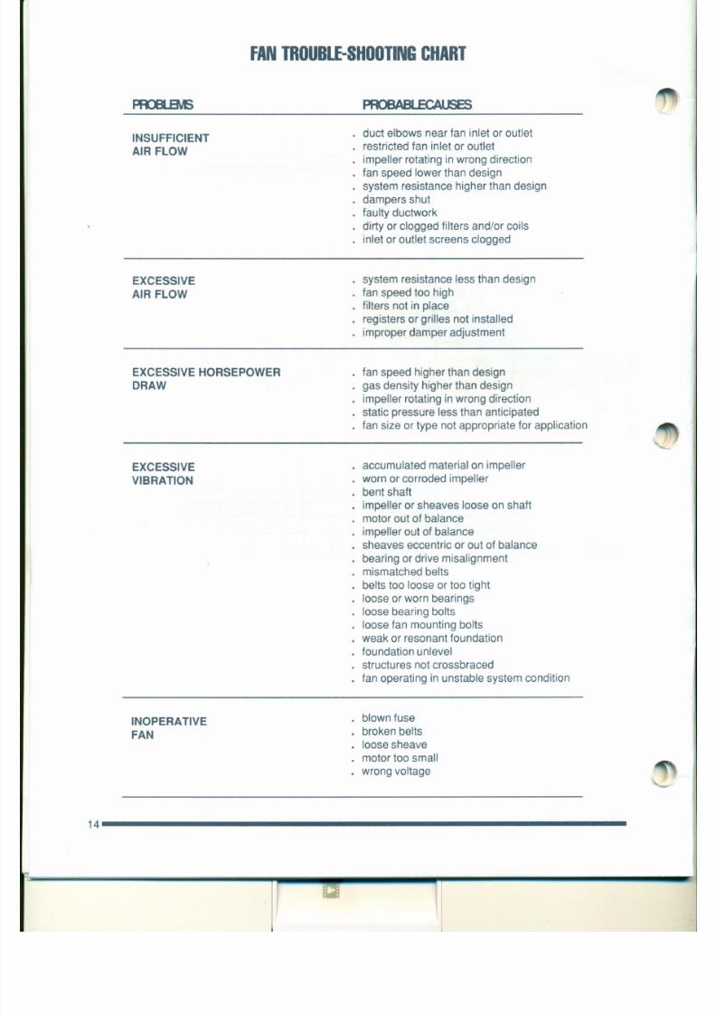
7/30/2019 MANUAL DE USUARIO GRANALLADORA (2).pdf
http://slidepdf.com/reader/full/manual-de-usuario-granalladora-2pdf 182/240
dirty or clogged filters and/or coils
inlet or outlet screens clogged
EXCESSIVE
AIR FLOW
system resistance less than design
fan speed too highfilters not in place
registers or grilles not installed
improper damper adjustment
EXCESSIVE HORSEPOWER
DRAW
fan speed higher than design
gas density higher than design
impeller rotating inwrong direction
static pressure less than anticipatedfan size or type not appropriate for application
EXCESSIVE
VIBRATION
accumulated material on impeller
worn or corroded impeller
O T H E R IN S T R U C T IO N S a n d U T E R A T U R E
FAN EQUIPMENT SERIAL No. MAY CONTAIN COMPO-
NENTS MANUFACTURED BY MANUFACTURERS OTHER THAN CML NORTHERN.
SUCH MANUFACTURERS MAY HAVE FURNISHED INSTRUCTIONS AND/OR OTHER
LITERATURE CONCERNING THEIR COMPONENT. A LIST OF SUCH INSTRUCTIONS
AND/OR OTHER LITERATURE FORWARDED WITH FAN EQUIPMENT
SERIAL No. IS GIVEN BELOW.
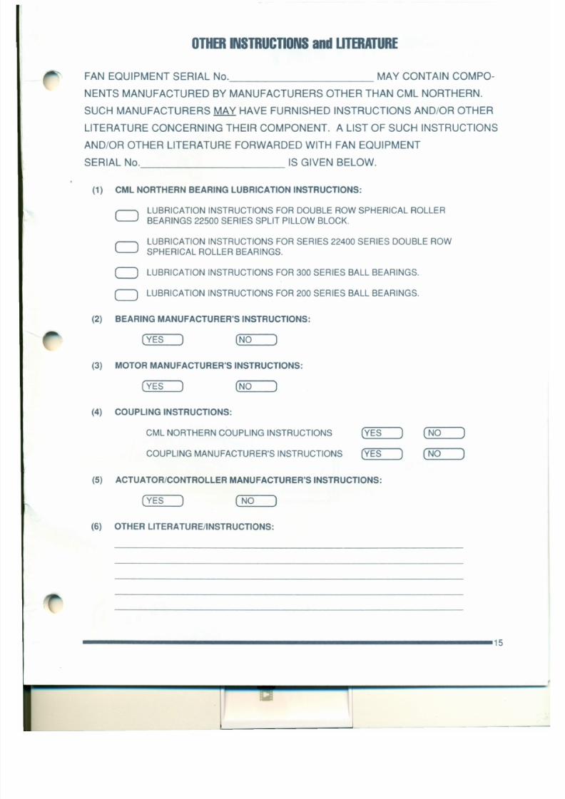
7/30/2019 MANUAL DE USUARIO GRANALLADORA (2).pdf
http://slidepdf.com/reader/full/manual-de-usuario-granalladora-2pdf 183/240
(1) CML NORTHERN BEARING LUBRICATION INSTRUCTIONS:
CJLUBRICATION INSTRUCTIONS FOR DOUBLE ROW SPHERICAL ROLLER
BEARINGS 22500 SERIES SPLIT PILLOW BLOCK.
LUBRICATION INSTRUCTIONS FOR SERIES 22400 SERIES DOUBLE ROW
SPHERICAL ROLLER BEARINGS.J
CJ
CJ
LUBRICATION INSTRUCTIONS FOR 300 SERIES BALL BEARINGS.
LUBRICATION INSTRUCTIONS FOR 200 SERIES BALL BEARINGS.
(2) BEARING MANUFACTURER'S INSTRUCTIONS:
(YES) (_N_O_-.J
(3) MOTOR MANUFACTURER'S INSTRUCTIONS:
E.ALDORMOTORS AND DRIVES

7/30/2019 MANUAL DE USUARIO GRANALLADORA (2).pdf
http://slidepdf.com/reader/full/manual-de-usuario-granalladora-2pdf 184/240
Integral Horsepower
AC Induction MotorsOOP,WPI, WPII Enclosure
Table of Contents
Section 1
General Information
Overview 1-1
Limited Warranty. . . . . . . . . . . . . . . . . . . . . . . . . . . . . . . . . . . . . . . . . . . . . . . . . . . . . . . . . . . . . . . . . . . . . . . . . . . . . . . 1-1
Safety Notice . . . . . . . . . . . . . . . . . . . . . . . . . . . . . . . . . . . . . . . . . . . . . . . . . . . . . . . . . . . . . . . . . . . . . . . . . . . . . . . . . . 1-2
Receiving ... . . . . . . . . . . . . . . . . . . . . . . . . . . . . . . . . . . . . . . . . . . . . . . . . . . . . . . . . . . . . . . . . . . . . . . . . . . . . . . . . . . 1-4
Storage . . . . . . . . . . . . . . . . . . . . . . . . . . . . . . . . . . . . . . . . . . . . . . . . . . . . . . . . . . . . . . . . . . . . . . . . . . . . . . . . . . . . . . . 1-4
Unpacking 1-4
Handling . . . . . . . . . . . . . . . . . . . . . . . . . . . . . . . . . . . . . . . . . . . . . . . . . . . . . . . . . . . . . . . . . . . . . . . . . . . . . . . . . . . . . . 1-4.
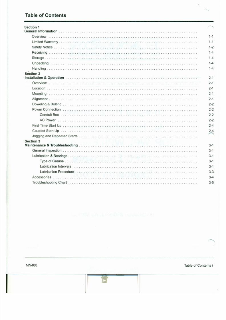
7/30/2019 MANUAL DE USUARIO GRANALLADORA (2).pdf
http://slidepdf.com/reader/full/manual-de-usuario-granalladora-2pdf 185/240
Section 2
Installation & Operation 2-1
Overview 2-1
Location 2-1
Mounting 2-1
Alignment . . . . . . . . . . . . . . . . . . . . . . . . . . . . . . . . . . . . . . . . . . . . . . . . . . . . . . . . . . . . . . . . . . . . . . . . . . . . . . . . . . . . . 2-1
Doweling & Bolting . . . . . . . . . . . . . . . . . . . . . . . . . . . . . . . . . . . . . . . . . . . . . . . . . . . . . . . . . . . . . . . . . . . . . . . . . . . . . 2-2
Power Connection 2-2
Conduit Box 2-2
AC Power 2-2
First Time Start Up . . . . . . . . . . . . . . . . . . . . . . . . . . . . . . . . . . . . . . . . . . . . . . . . . . . . . . . . . . . . . . . . . . . . . . . . . . . . . 2-4
Coupled Start Up 2-4
J ogging and Repeated Starts .
Section 3
Maintenance & Troubleshooting. . . . . . . . . . . . . . . . . . . . . . . . . . . . . . . . . . . . . . . . . . . . . . . . . . . . . . . . . . . . . . . . . . . . 3-1
General Inspection . . . . . . . . . . . . . . . . . . . . . . . . . . . . . . . . . . . . . . . . . . . . . . . . . . . . . . . . . . . . . . . . . . . . . . . . . . . . . 3-1
Section 1
General Information
Important:
This manual contains general procedures that apply to Baldor Motor products. Be sure to read and ~
understand the Safety Notice statements in this manual. For your protection, do not install, operate orattempt to perform maintenance procedures until you understand the Warning and Caution statements. A
Warning statement indicates a possible unsafe condition that can cause harm to personnel. A Caution
statement indicates a condition that can cause damage to equipment.
This instruction manual is not intended to include a comprehensive listing of all details for all
procedures required for installation, operation and maintenance. This manual describes generalguidelines that apply to most of the motor products shipped by Baldor. If you have a question
about a procedure or are uncertain about any detail, Do Not Proceed. Please contact your Baldordistributor for more information or clarification.
Overview
7/30/2019 MANUAL DE USUARIO GRANALLADORA (2).pdf
http://slidepdf.com/reader/full/manual-de-usuario-granalladora-2pdf 186/240
Before you install, operate or perform maintenance, become familiar with the following:
• NEMA Publication MG-2, Safety Standard for Construction and guidefor Selection, Installation and Use of Electric Motors and Generators.
• The National Electrical Code
• Local codes and Practices
Limited Warranty
1. Baldor Electric motors are warranted for a period of one (1) year, from date of shipment from the factory or factory
warehouse against defects in material and workmanship. To allow for stocking and/or fabrication period and to
provide one year of actual service, the warranty period is extended for an additional period of six (6) months for atotal of eighteen (18) months from the original date of shipment from the factory or factory warehouse stock. In no
case will the warranty period be extended for a longer period. Baldor extends this limited warranty to each buyer
of the electric motor for the purpose of resale and to the original purchaser for use.
2. Baldor will, at its option repair or replace a motor which fails due to defects in material or workmanship during thewarranty period if:
a. the purchaser presents the defective motor at or ships it prepaid to, the Baldor plant in Fort Smith, Arkansaor one of the Baldor Authorized Service Centers and
b. the purchaser gives written notification concerning the motor and the claimed defect including the datepurchased, the task performed by the Baldor motor and the problem encountered.
9ty Notice: This equipment contains high voltage! Electrical shock can cause serious or fatal injury.
Only qualified personnel should attempt installation, operation and maintenance ofelectrical equipment.
Be sure that you are completely familiar with NEMA publication MG-2, safety standards
for construction and guide for selection, installation and use of electric motors and
generators, the National Electrical Code and local codes and practices. Unsafe
installation or use can cause conditions that lead to serious or fatal injury. Only qualifiedpersonnel should attempt the installation, operation and maintenance of this equipment.
WARNING: Do not touch electrical connections before you first ensure that
power has been disconnected. Electrical shock can cause serious
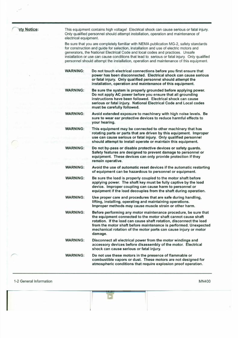
7/30/2019 MANUAL DE USUARIO GRANALLADORA (2).pdf
http://slidepdf.com/reader/full/manual-de-usuario-granalladora-2pdf 187/240
WARNING:
WARNING:
WARNING:
WARNING:
or fatal injury. Only qualified personnel should attempt the
installation, operation and maintenance of this equipment.
Be sure the system is properly grounded before applying power.
Do not apply AC power before you ensure that all grounding
instructions have been followed. Electrical shock can cause
serious or fatal injury. National Electrical Code and Local codes
must be carefully followed.
Avoid extended exposure to machinery with high noise levels. Be
sure to wear ear protective devices to reduce harmful effects to
your hearing.
This equipment may be connected to other machinery that has
rotating parts or parts that are driven by this equipment. Improper
use can cause serious or fatal injury. Only qualified personnelshould attempt to install operate or maintain this equipment.
Do not by-pass or disable protective devices or safety guards.
Safety features are designed to prevent damage to personnel or
equipment. These devices can only provide protection if they
remain operative.
Safety Notice Continued
WARNING:
WARNING:
Caution:
Motors that are to be used in flammable and/or explosive
atmospheres must display the UL label on the nameplate.
Specific service conditions for these motors are defined in
NEC 70-599.
UL rated motors must only be serviced by authorized BaldorService Centers if these motors are to be returned to a flammable
and/or explosive atmosphere.
To prevent premature equipment failure or damage, only qualified
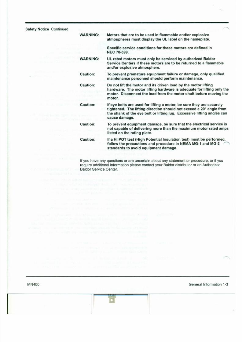
7/30/2019 MANUAL DE USUARIO GRANALLADORA (2).pdf
http://slidepdf.com/reader/full/manual-de-usuario-granalladora-2pdf 188/240
Caution:
Caution:
Caution:
Caution:
maintenance personnel should perform maintenance.
Do not lift the motor and its driven load by the motor lifting
hardware. The motor lifting hardware is adequate for lifting only the
motor. Disconnect the load from the motor shaft before moving the
motor.
If eye bolts are used for lifting amotor, be sure they are securely
tightened. The lifting direction should not exceed a20° angle from
the shank of the eye bolt or lifting lug. Excessive lifting angles can
cause damage.
To prevent equipment damage, be sure that the electrical service is
not capable of delivering more than the maximum motor rated amps
listed on the rating plate.
If a HI POT test (High Potential Insulation test) must be performed,follow the precautions and procedure in NEMA MG-1and MG-2
standards to avoid equipment damage.
Ifyou have any questions orare uncertain about any statement or procedure, or if you
Section 2
Instal lation & Operation
Installation should conform to the National Electrical Code as well as local codes and ~
practices. When other devices are coupled to the motor shaft, be sure to installprotective devices to prevent future accidents. Some protective devices include,
coupling, belt guard, chain guard, shaft covers etc. These protect against accidentalcontact with moving parts. Machinery that is accessible to personnel should providefurther protection in the form of guard rails, screening, warning signs etc.
The motor should be installed in an area that is protected from direct sunlight, corrosives,harmful gases or liquids, dust, metallic particles, and vibration. Exposure to these canreduce the operating life and degrade performance. Be sure to allow clearance for
ventilation and access for cleaning, repair, service and inspections. Ventilation isextremely important. Be sure the area for ventilation is not obstructed. Obstructions will
Overview
Location
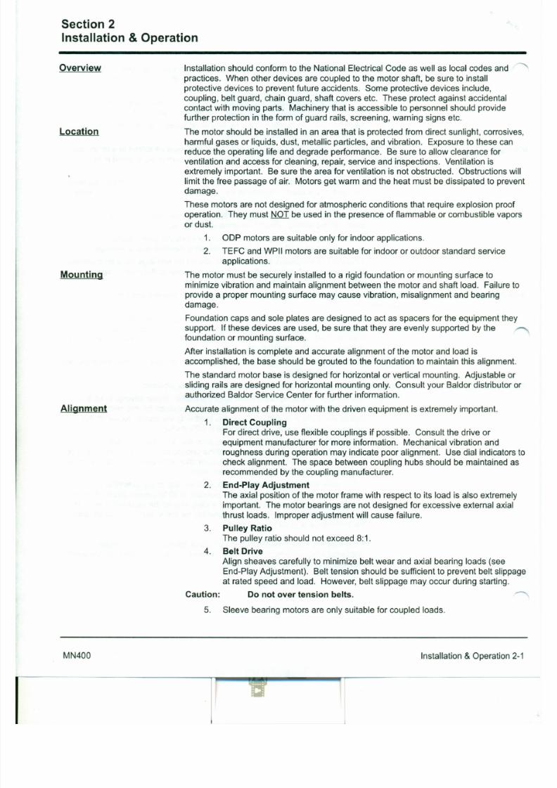
7/30/2019 MANUAL DE USUARIO GRANALLADORA (2).pdf
http://slidepdf.com/reader/full/manual-de-usuario-granalladora-2pdf 189/240
Mounting
limit the free passage of air. Motors get warm and the heat must be dissipated to prevent
damage.
These motors are not designed for atmospheric conditions that require explosion proof
operation. They must NOT be used in the presence of flammable or combustible vapors
or dust.1. OOP motors are suitable only for indoor applications.
2. TEFC and WPII motors are suitable for indoor or outdoor standard service
applications.
The motor must be securely installed to a rigid foundation or mounting surface to
minimize vibration and maintain alignment between the motor and shaft load. Failure to
provide a proper mounting surface may cause vibration, misalignment and bearing
damage.
Foundation caps and sole plates are designed to act as spacers for the equipment theysupport. Ifthese devices are used, be sure that they are evenly supported by the
foundation or mounting surface.
After installation is complete and accurate alignment of the motor and load isaccomplished, the base should be grouted to the foundation to maintain this alignment.
The standard motor base is designed for horizontal or vertical mounting. Adjustable or
vel ing & Bol ting After proper alignment is verified, dowel pins should be inserted through the motor feet
into the foundation. This will maintain the correct motor position should motor removal be
required. (Baldor motors are designed for doweling.)
1. Drill dowel holes in diagonally opposite motor feet in the locations provided.
2. Drill corresponding holes in the foundation.
3. Ream all holes.
4. Install proper fitting dowels.
5. Mounting bolts must be carefully tightened to prevent changes in alignment.
Use a flat washer and lock washer under each nut or bolt head to hold the
motor feet secure. Flanged nuts or bolts may be used as an alternative to
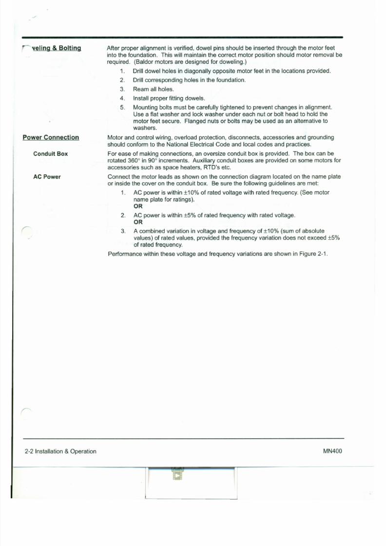
7/30/2019 MANUAL DE USUARIO GRANALLADORA (2).pdf
http://slidepdf.com/reader/full/manual-de-usuario-granalladora-2pdf 190/240
Power Connection
Conduit Box
AC Power
washers.
Motor and control wiring, overload protection, disconnects, accessories and grounding
should conform to the National Electrical Code and local codes and practices.
For ease of making connections, an oversize conduit box is provided. The box can berotated 3600 in 900 increments. Auxiliary conduit boxes are provided on some motors for
accessories such as space heaters, RTD's etc.
Connect the motor leads as shown on the connection diagram located on the name plate
or inside the cover on the conduit box. Be sure the following guidelines are met:
1. AC power is within ±10% of rated voltage with rated frequency. (See motor
name plate for ratings).
OR
2. AC power is within ±5% of rated frequency with rated voltage.
OR
3. A combined variation in voltage and frequency of ±10% (sum of absolute
values) of rated values, provided the frequency variation does not exceed ±5%
of rated frequency.
Performance within these voltage and frequency variations are shown in Figure 2-1.
+20
+15
' ; € +10-1oeco
E +5L-
0
Figure 2-1 Motor Per formance VS Voltage Var iations
/Maximum
Full-Load
'"Torque
Current
- , V 'r-,,
Full-LoadPower / curr~Factor - - - - -. " - /
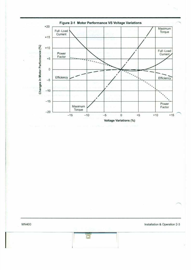
7/30/2019 MANUAL DE USUARIO GRANALLADORA (2).pdf
http://slidepdf.com/reader/full/manual-de-usuario-granalladora-2pdf 191/240
't:41c . .
0-
0-0~c : - 5!II41Clc:co
- 10c:0
- 15
- 20
/'- -~ V '.
.-/
-- - ,/ --
-.• . "' . . . . - - -- - - - - - . . . • . . . . . •
Efficiencyv " " -
/. . . .
. . Efficiency
/. . . . . . . . . .
/'. . . .
. .
/. . . . . . . . . .
/'. . . .
/ PowerMaximum Factor
Torque
- 15 +10 +1510 - 5 o +5
Voltage Variations (%)
+20
+15
~ +10.. . . .
Q)(.)
eco
E +5. . .0
Figure 2-1 Motor Performance VS Voltage Var iations
/Maximum
Full-Load
~
TorqueCurrent
- .
,
r-,, Full-Load
Power / curr~Factor --. ... . . . . • • . • . • /...
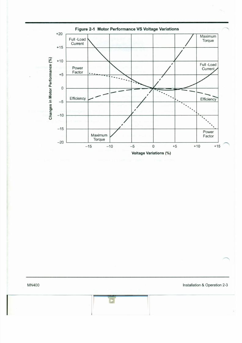
7/30/2019 MANUAL DE USUARIO GRANALLADORA (2).pdf
http://slidepdf.com/reader/full/manual-de-usuario-granalladora-2pdf 192/240
't:Q)
Il.
0. .0-0:!e - 5II)Q)
Olc:c o
- 10c:0
- 15
- 20
/'~ V'.
.,/
-- - /. --
-'. . . . . . . - -
-, •. •. - - . . . . . . . . .
EfficiencyV " " -
/•. •.
•. Efficiency
/•. •. •. • . •.
~•. • .
• .
/• . •. •. •.
. •.
/'.• .
.•.
/ PowerMaximum Factor
Torque
- 15 o +10 +1510 - 5 +5
Voltage Variations (%)
'tTimeStart Up Be sure that all power to motor and accessories is off. Be sure the motor shaft is
disconnected from the load and will not cause mechanical rotation of the motor shaft.
1. Make sure that the mechanical installation is secure. All bolts and nuts are
tightened etc.
2. If motor has been in storage or idle for some time, check winding insulationintegrity with a Megger.
3. Inspect all electrical connections for proper termination, clearance, mechanicalstrength and electrical continuity.
4. Be sure all shipping materials and braces (if used) are removed from motor
shaft.
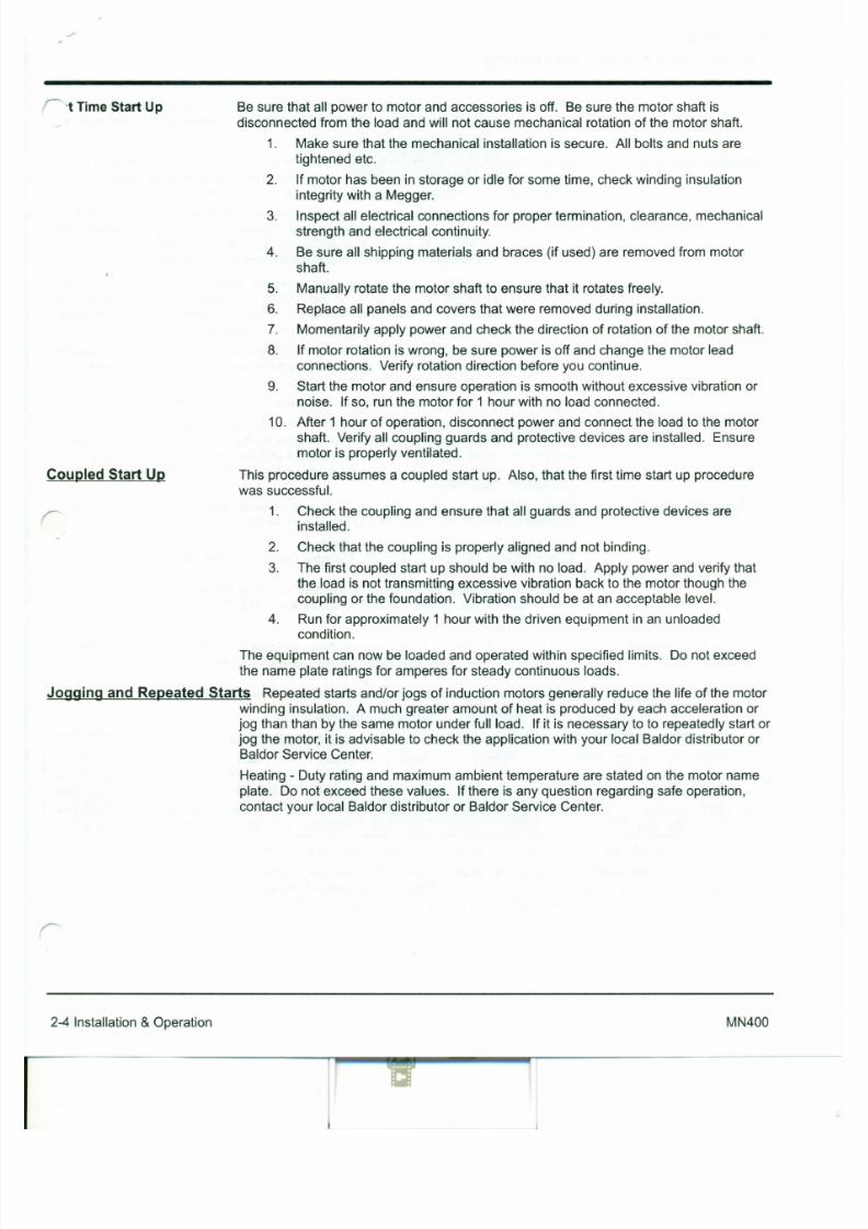
7/30/2019 MANUAL DE USUARIO GRANALLADORA (2).pdf
http://slidepdf.com/reader/full/manual-de-usuario-granalladora-2pdf 193/240
Coupled Start Up
5. Manually rotate the motor shaft to ensure that it rotates freely.
6. Replace all panels and covers that were removed during installation.
7. Momentarily apply power and check the direction of rotation of the motor shaft.
8. Ifmotor rotation is wrong, be sure power is off and change the motor lead
connections. Verify rotation direction before you continue.
9. Start the motor and ensure operation is smooth without excessive vibration or
noise. Ifso, run the motor for 1 hour with no load connected.
10. After 1 hour of operation, disconnect power and connect the load to the motor
shaft. Verify all coupling guards and protective devices are installed. Ensure
motor is properly ventilated.
This procedure assumes a coupled start up. Also, that the first time start up procedurewas successful.
1. Check the coupling and ensure that all guards and protective devices areinstalled.
2. Check that the coupling is properly aligned and not binding.
3. The first coupled start up should be with no load. Apply power and verify thatthe load is not transmitting excessive vibration back to the motor though the
Section 3
Maintenance & Troubleshooting
WARNING: UL rated motors must only be serviced by authorized Baldor
Service Centers if these motors are to be returned to a flammable
and/or explosive atmosphere.
Inspect the motor at regular intervals, approximately every 500 hours of operation or
every 3 months, whichever occurs first. Keep the motor clean and the ventilation
openings clear. The following steps should be performed at each inspection:
WARNING: Do not touch electrical connections before you first ensure thatpower has been disconnected. Electrical shock can cause serious
or fatal injury. Only qualified personnel should attempt the
installation, operation and maintenance of this equipment.
1. Check that the motor is clean. Check that the interior and exterior of the motor
General Inspection
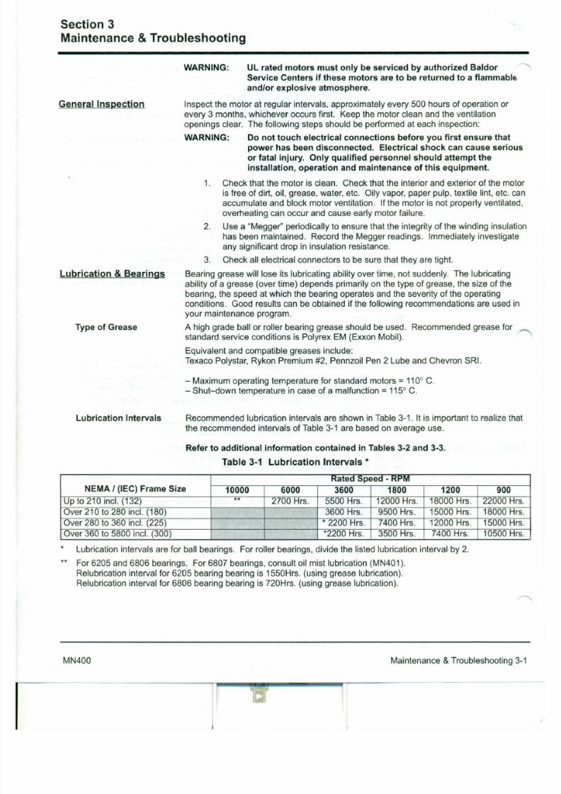
7/30/2019 MANUAL DE USUARIO GRANALLADORA (2).pdf
http://slidepdf.com/reader/full/manual-de-usuario-granalladora-2pdf 194/240
is free of dirt, oil, grease, water, etc. Oily vapor, paper pulp, textile lint, etc. can
accumulate and block motor ventilation. If the motor is not properly ventilated,
overheating can occur and cause early motor failure.
2. Use a "Megger" periodically to ensure that the integrity of the winding insulation
has been maintained. Record the Megger readings. Immediately investigate
any significant drop in insulation resistance.
3. Check all electrical connectors to be sure that they are tight.
Bearing grease will lose its lubricating ability over time, not suddenly. The lubricating
ability of a grease (over time) depends primarily on the type of grease, the size of the
bearing, the speed at which the bearing operates and the severity of the operatingconditions. Good results can be obtained if the following recommendations are used in
your maintenance program.
A high grade ball or roller bearing grease should be used. Recommended grease forstandard service conditions is Polyrex EM (Exxon Mobil).
Equivalent and compatible greases include:
Texaco Polystar, Rykon Premium #2, Pennzoil Pen 2 Lube and Chevron SRI.
Lubrication & Bearings
Type of Grease
- Maximum operating temperature for standard motors = 110° C.
Table 3-2 Service Condit ions
Severity of Service Ambient Temperature Atmospheric Type of Bearmg
Maximum Contamination
Standard 40° C Clean, Little Corrosion Deep Groove Ball Bearing
Severe 50° C Moderate dirt, Corrosion Ball Thrust, Roller
Extreme >50° C* or Severe dirt, Abrasive dust, All Bearings
Class H Insulation CorrosionLow Temperature <-30° C **
* Special high temperature grease is recommended (Dow Corning DC44). Note that Dow Corning DC44 grease does
not mix with other grease types. Thoroughly clean bearing & cavity before adding grease.
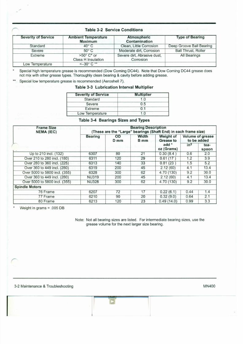
7/30/2019 MANUAL DE USUARIO GRANALLADORA (2).pdf
http://slidepdf.com/reader/full/manual-de-usuario-granalladora-2pdf 195/240
** Special low temperature grease is recommended (Aeroshell 7).
Table 3-3 Lubricat ion In terval Multi pl ier
Severity of Service Multiplier
Standard 1.0Severe 0.5
Extreme 0.1
Low Temperature 1.0
Table 3-4 Bearings Sizes and Types
Frame Size Bearing Description
NEMA (IEC) (These are the " Large" bearings (Shaft End) in each frame size)
Bearing 00 Width Weight of Volume of grease
Omm Bmm Grease to to be addedi.--
add * in.) tea-
- oz (Grams) spoon
Up to 210 incl. (132) 6307 80 21 0.30 (8.4 ) 0.6 2.0
Over 210 to 280 incl. (180) 6311 120 29 0.61 (17 ) 1.2 3.9
Over 280 to 360 incl. (225) 6313 140 33 0.81 (23 ) 1.5 5.2
Be sure that the grease you are adding to the motor is compatible with the grease alre<">
in the motor. Consult your Baldor distributor or an authorized service center if a qrease
other than the recommended type is to be used.
Caution: To avoid damage to motor bearings, grease must be kept free of dirt.
For an extremely dirty environment, contact your Baldor distributor or
an authorized Baldor Service Center for additional information.
With Grease Outlet Plug1. Clean all grease fittings.
2. Remove grease outlet plug.
3. If motor is stopped, add the recommended amount of grease.
Lubrication Procedure
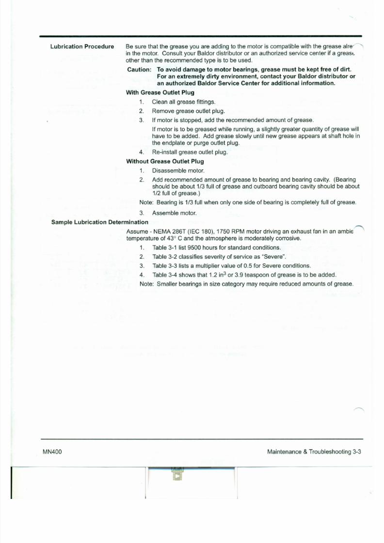
7/30/2019 MANUAL DE USUARIO GRANALLADORA (2).pdf
http://slidepdf.com/reader/full/manual-de-usuario-granalladora-2pdf 196/240
If motor is to be greased while running, a slightly greater quantity of grease will
have to be added. Add grease slowly until new grease appears at shaft hole in
the endplate or purge outlet plug.
4. Re-install grease outlet plug.
Without Grease Outlet Plug
1. Disassemble motor.
2. Add recommended amount of grease to bearing and bearing cavity. (Bearing
should be about 1/3 full of grease and outboard bearing cavity should be about
1/2 full of grease.)
Note: Bearing is 1/3 full when only one side of bearing is completely full of grease.
3. Assemble motor.
Sample Lubrication Determination
Assume - NEMA 286T (IEC 180), 1750 RPM motor driving an exhaust fan in an amble
temperature of 43° C and the atmosphere is moderately corrosive.
1. Table 3-1 list 9500 hours for standard conditions.
2. Table 3-2 classifies severity of service as "Severe".
~essories The following is a partial list of accessories available from Baldor.
Contact your Baldor distributor for availability and pricing information.
Note: Space heaters and RTD's are standard on some motors.
Bearing RTD
RTD (Resistance Temperature Detector) devices are used to measure or
monitor the temperature of the motor bearing during operation.
Bearing Thermocouples
Used to measure or monitor bearing temperatures.
Bearing Thermostat
Temperature device that activates when bearing temperatures are excessive.
Used with an external circuit to warn of excessive bearing temperature or to

7/30/2019 MANUAL DE USUARIO GRANALLADORA (2).pdf
http://slidepdf.com/reader/full/manual-de-usuario-granalladora-2pdf 197/240
shut down a motor.
Condui t Boxes
Optional conduit boxes are available in various sizes to accommodate
accessory devices.Cord & Plug Assemb ly
Adds a line cord and plug for portable applications.
Drains and Breathers
Stainless steel drains with separate breathers are available.
Drip Covers
Designed for use when motor is mounted in a vertical position. Contact your
Baldor distributor to confirm that the motor is designed for vertical mounting.
Fan Cover & Lint ScreenTo prevent build-up of debris on the cooling fan.
Nameplate
Additional stainless steel nameplates are available.
Roller Bearings
Recommended for belt drive applications with a speed of 1800 RPM or less.
Table 3-5 Troubleshooting Chart
Symptom Possible Causes Possible Solutions
Motor will not start Usually caused by line trouble, such Check source of power. Check overloads, fuses,as, single phasing at the starter. controls, etc.
Excessive humming High Voltage. Check input line connections.
Eccentric air gap. Have motor serviced at local Baldor service center.
Motor Over Heating Overload. Compare actual amps Locate and remove source of excessive friction in(measured) with nameplate rating. motor or load.
Reduce load or replace with motor of greater capacity.
Single Phasing. Check current at all phases (should be approximately. equal) to isolate and correct the problem .
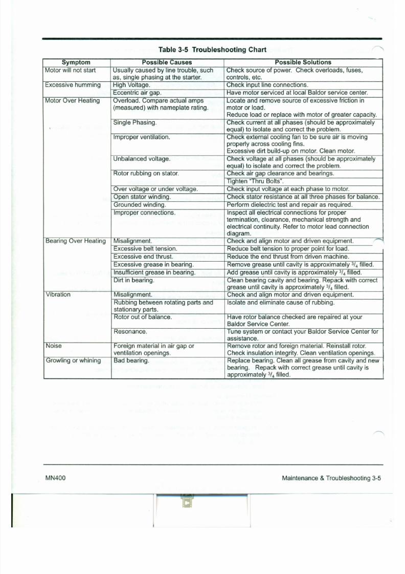
7/30/2019 MANUAL DE USUARIO GRANALLADORA (2).pdf
http://slidepdf.com/reader/full/manual-de-usuario-granalladora-2pdf 198/240
Improper ventilation. Check external cooling fan to be sure air is movingproperly across cooling fins.Excessive dirt build-up on motor. Clean motor.
Unbalanced voltage. Check voltage at all phases (should be approximately
equal) to isolate and correct the problem.Rotor rubbing on stator. Check air gap clearance and bearings.
Tighten 'Thru Bolts".
Over voltage or under voltage. Check input voltage at each phase to motor.
Open stator winding. Check stator resistance at all three phases for balance.
Grounded winding. Perform dielectric test and repair as required.
Improper connections. Inspect all electrical connections for propertermination, clearance, mechanical strength and
electrical continuity. Refer to motor lead connection
diagram.Bearing Over Heating Misalignment. Check and align motor and driven equipment. ,,-
Excessive belt tension. Reduce belt tension to proper point for load.
Excessive end thrust. Reduce the end thrust from driven machine.
Excessive grease in bearing. Remove grease until cavity is approximately 3h filled.
Insufficient grease in bearing. Add grease until cavity is approximately 3/4 filled.
1gested bearing and wind ing RTD set ti ng guidel ines
Most large frame AC Baldor motors with a 1.15 service factor are designed to operate
below a Class B (80°G) temperature rise at rated load and are built with a Class H
winding insulation system. Based on this low temperature rise, RTD (Resistance
Temperature Detectors) settings for Class B rise should be used as a starting point.
Some motors with 1.0 service factor have Class F temperature rise.
The following tables show the suggested alarm and trip settings for RTDs. Properbearing and winding RTD alarm and trip settings should be selected based on these
tables unless otherwise specified for specific applications.
If the driven load is found to operate well below the initial temperature settings under
normal conditions, the alarm and trip settings may be reduced so that an abnormal
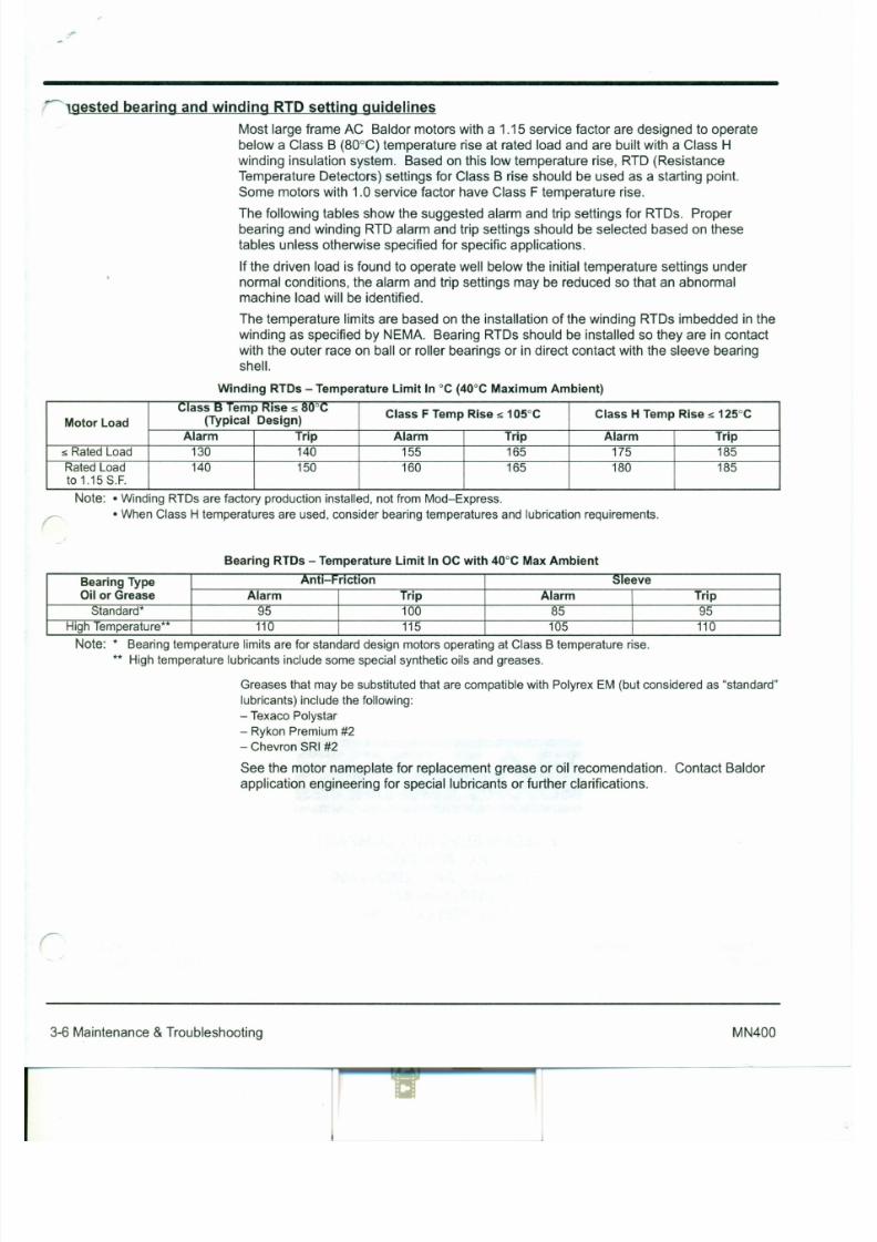
7/30/2019 MANUAL DE USUARIO GRANALLADORA (2).pdf
http://slidepdf.com/reader/full/manual-de-usuario-granalladora-2pdf 199/240
machine load will be identified.
The temperature limits are based on the installation of the winding RTDs imbedded in the
winding as specified by NEMA. Bearing RTDs should be installed so they are in contact
with the outer race on ball or roller bearings or in direct contact with the sleeve bearing
shell.
Wind ing RTDs - Temperature Limi t In °C (40°C Maximum Ambient)
Cl ass B Temp Rise :s 80°CClass F Temp Rise :s 105°C Class H Temp Rise :s 125°C
Motor Load (Typical Design)
Alarm Trip Alarm Trip Alarm Trip
:s RatedLoad 130 140 155 165 175 185RatedLoad 140 150 160 165 180 185to1.15S.F.
Note: •WindingRTDs are factory production installed, notfromMod-Express.
•WhenClass H temperatures are used, consider bearingtemperatures and lubrication requirements.r:
Bearing RTDs - Temperature Limit In OC with 40°C Max Ambient
Bear ing Type Antt-Frfctlon Sleeve
Oi l or Grease Alarm Trip Alarm Trip
7/30/2019 MANUAL DE USUARIO GRANALLADORA (2).pdf
http://slidepdf.com/reader/full/manual-de-usuario-granalladora-2pdf 200/240

7/30/2019 MANUAL DE USUARIO GRANALLADORA (2).pdf
http://slidepdf.com/reader/full/manual-de-usuario-granalladora-2pdf 201/240
1 The S-VECO brush is self cleaning!
The S-\l:U i's ultra high brush SIWt'd cn'ilks
l't'lltrifugal Inn'c' which comhinr-d with tilt'
OPC'llillg of tilt' brush pat tr- ru L IS the brush
,'ours('s around the sheaves. aids the brush
ill t luowuu; off all of tilt' rt'ftl.-;t' or parttrul.ite
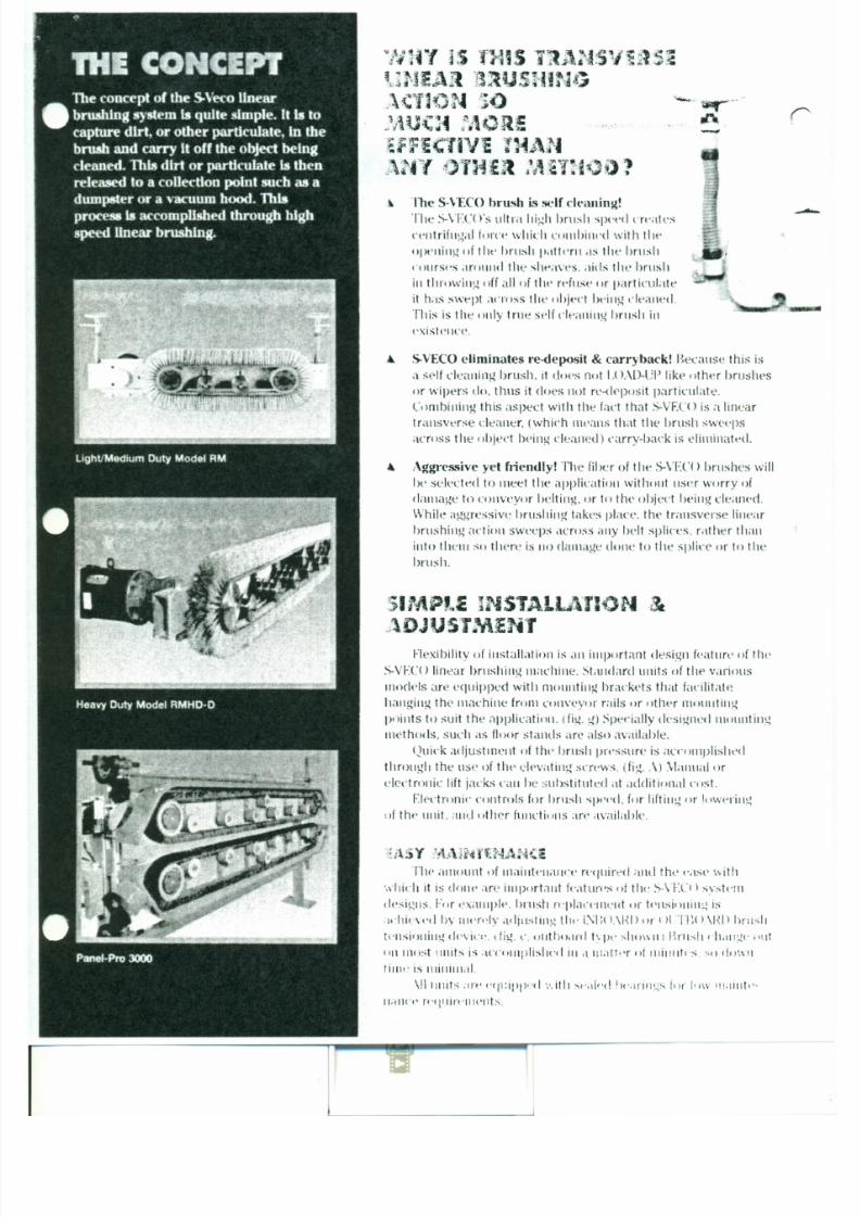
7/30/2019 MANUAL DE USUARIO GRANALLADORA (2).pdf
http://slidepdf.com/reader/full/manual-de-usuario-granalladora-2pdf 202/240
it hdS swept across tilt' object ht'illg t'lt'ililed.
This is the only true self Clt'allillg brush in
oxistencc.
.•. S-VECO eliminates re-deposit & carry hack! Because this isitself cle<tlling brush. it clot's not IDAD-UP like other brushes
or wipers do. thus it does not re-deposit particulate.
Cornblntug this aspect with the fad that S-VF.CO is d linear
transverse cleaner, (which uu-aus that the brush swee-ps
across the ohjed Iwillg cleaned) carry-back is e luuiua te -cl.
.•. Aggres.<;ive yet friendly! The fiber of the S-VEC() brushes will
Ilt' selected to meet the application without use-rworry of
damage to conveyor helting, or tn the object beillg cleaned.While aggrl'ssiv(~ brushing takes place. the transverse linear
hrushuu] action sweeps dUOSS any Il('11splices. rather than
into th('111so there is 110damage done to the splice or to tile
brush.
_\
\
\._.~.J \
i\
C\' .\
\,
t.
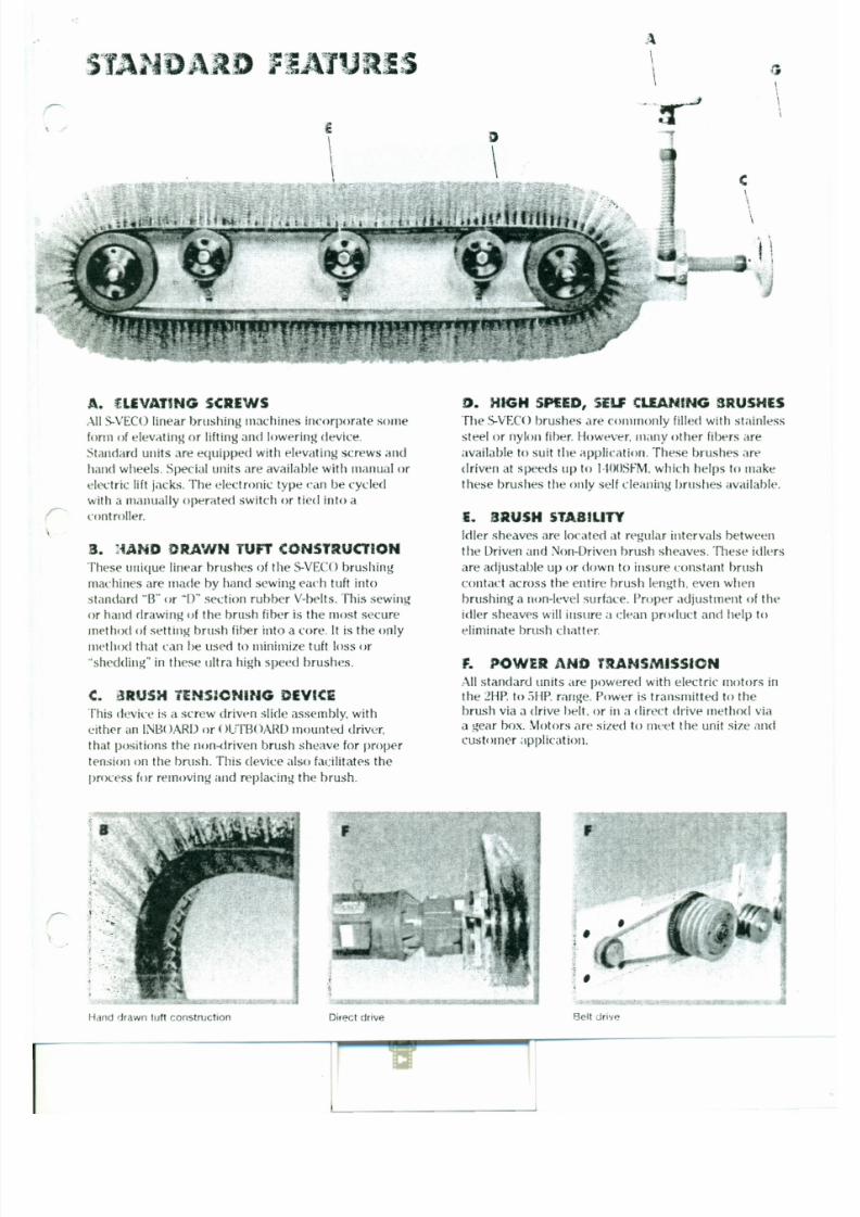
7/30/2019 MANUAL DE USUARIO GRANALLADORA (2).pdf
http://slidepdf.com/reader/full/manual-de-usuario-granalladora-2pdf 203/240
A. fLE VATING SCREWS
AllS-VECOlinear brushing machines incorporate some
formof elevating or lifting and lowering device.
Standardunits areequipped with elevating screws and
handwheels. Special units areavailable with manual or
electric lift jacks. The electronic type canbecycled
with amanually operated switch or tied into acontroller.
3. : iA ND CRA'NN TUFT CONSTRUCTION
Theseunique linear brushes of the S-VECObrushing
machinesaremade by hand sewingeach tuft into
D . HIG H SHED, SE LF CLE ANIN G 8RUSHE S
The S-VECObrushes are commonly filled with stainless
steel or nylon fiber. However. many other fibers are
available to suit the application. These brushes art'
driven atspeedsup to l,toOSFM,which helps to make
these brushes the only self cleaning brushes available,
£. BRUSH STABILITY
Idler sheavesare located at regular.intervals between
the Driven andNon-Driven brush sheaves.These idlers
areadjustable upor down to insure constant brush
contact across the entire brush length, evenwhen
' \ l l ' '~lJCA'r30'''1 S'f - J fI '. ',<" " .~"
J•. , ,.l, ~ .,.• ~, .." '., '., . i~Ji~
.'
\It'diulll and Heavy Duty S-VEC() units art' providing
apositive effect to the bottom line.
Lower Operating and ~aintenance Costs
•Reduce lost material clue to carryback
•Reduce carrvback clean up time
•Reduce belt and idler wear
•Reduce belt cleaner system maintenance time due
to S-VETOfeatures and benefits
t':<)~l:'·~oa~{
There are many standard and special S-VEC< rs at

7/30/2019 MANUAL DE USUARIO GRANALLADORA (2).pdf
http://slidepdf.com/reader/full/manual-de-usuario-granalladora-2pdf 204/240
work ill foundries around the world, helping to lower
operating and maintenance costs while increasing
production rates.
Effective Cleaning
•Mold Car Tops
•Hottorn Boards
•SandConveyors
• Recovery SandConveyors
V'JOOO '..YORKING PLANTS
S-VECO , combined with a dust collection system has
proven to be an effective way to do light to mediumsanding and dusting operations.
•Door plants
•Paneling plants
•Plywood plants
Extra-H e a" , DutyL in ear Bru sh ing Mach in e
HD·D
Fe u r e s• NEW '- ligh t w eigh t, f ie ld te sted de sign
• En ergy e f f ic ie n t, e le c tric mo to rs -.e-~~
• A ll · s eale d b eari n gs

7/30/2019 MANUAL DE USUARIO GRANALLADORA (2).pdf
http://slidepdf.com/reader/full/manual-de-usuario-granalladora-2pdf 205/240
• L arge se le c t ion o f ste e l &
syn the tic brush f ibe rs
• C on tour idle rs
• H igh to rque , pow er cog drive be lts
• D ire ct drive syste m
• M an y option s availabl e
B e n e f i l s• Short e st ove rall le n gth available
t' • as e o f In stallation
/. L ow main t e nan ce costs
• Excep t iona l c l ean ing
• P ro ve n de sign
s· C MD·Ixtra-Heavy Duty linear 8ruslting Macltine
TOP V IEW
TAKEU P O PT 1O ~S
~~ ~
Standa~dE q u i p m e n t1. HEAVY DUTY BRUSHES
M o d e l R M H D - D u t i l i z e s t h r e e D s e c t i o n b e l t b r u s h e s .
E a c h b r u s h i s t i t l e d w i t h t w o r o w s o f b r u s h f i b e r f r o m
a w i d e as so rtm en t o f m a t e r ia l t y p e s a n d s i z e s . B r u s h e s
w i l l b e ma de t o s u it t h e applic ati on .
S tan dard t r im l e n g t h ( b r i s t l e le n g t h ) is 3- 1/2", a n d t h e
a p p r o x im a t e f a c e w id t h o f t h r e e b r u s h e s i s 3 " . O t h e r
t r im l e n g t h s a r e a v a il a b le .
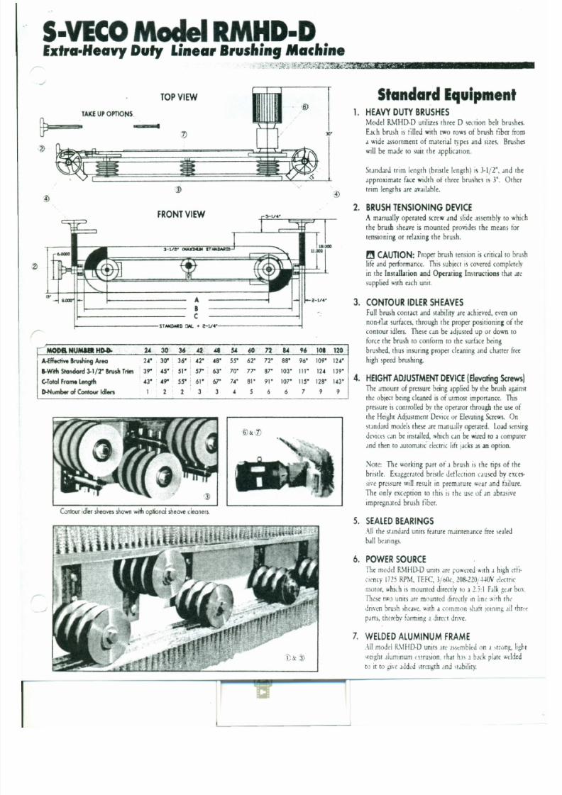
7/30/2019 MANUAL DE USUARIO GRANALLADORA (2).pdf
http://slidepdf.com/reader/full/manual-de-usuario-granalladora-2pdf 206/240
FRONT V IEW
A
B
C
f----------sr_D tWe-V4----------I
.-JMODI l NUMIEI tfN. 1 4 - 30· 36: ,42 i 48 5.( 6~ .72 84 96 101 120
A -E f f t c tive B rv ih in g Ar ea U' . 30" : 36 ' 4 2' 48' 55' 62 ' 72' 88 ' 9 6 ' 109 ' 124 ". .
I-W r!h S t an d ard 3 -1 /2" Brv ih T rim : 39' : 4 5" : 51 " 57 ' • 63 ' 70' 7 l " 8 l " 103 ' 1 11 ' 124 139':
CTot al Fr am . Length 4 3" : 4 9" 55 " 61 " : 67 ' 74 ' 81 ' 91 ' 107' liS' 128 ' 1 4 3'
2. BRUSHTENSIONING DEVICEA m a n u a l l y o p e r a t e d s c r e w a n d s li d e a s s e m b l y t o w h i c h
t h e b ru sh s h e a v e i s m o u n t e d p r o v id e s t h e m e a n s t o r
t e n s i o n i n g o r r e l a x i n g t h e b r u s h .
m CAUTION: P r o p er b ru sh t e n s i o n i s c r i t ic a l t o b r u s h
li f e a n d p e r f o r m a n c e . T h is s u b j e c t i s c o v e r e d c o m p l e t e l y
i n t h e I n s t a ll a t i o n a n d O p e r a t in g I n s t r u c t i o n s t h a t are
s u p p l ie d w it h e a c h u n i t .
3. CONTOUR IDLERSHEAVESF u l l b r u s h c o n t a c t a n d s t a b il i t y a re a c h i e v e d , e v e n o n
non- fla t s u r f a c e s , t h r o u g h t h e p r o p e r p o s i t io n i n g o f t h e
c o n t o u r i d l e rs . T h e s e c a n b e a d ju st e d u p o r d o w n t o
f o r c e t h e b r u s h t o c o n f o r m t o t h e s u r f a c e b e i n g
b r u s h e d , t h u s i n s u r i n g p r o p e r c le a n i n g a n d c h a t t e r f r e e
h i g h s p ee d b ru sh i n g .
4. HEIG HTADJ USTMEN TDEVICE( E le va ti n g S c r e w s l
"
CAUTION!BRUSH BELTS MUST NOT
BE OVERTIGHTENED!THESE BELTS DO NOT
7/30/2019 MANUAL DE USUARIO GRANALLADORA (2).pdf
http://slidepdf.com/reader/full/manual-de-usuario-granalladora-2pdf 207/240
TRANSMIT ANY POWER.
HEAVY PRESSURE WILLDESTROY THE UNIT
BEARINGS.
S i n c e 1905
w w w .s c h a e f e r b r u s h . c o m
MODEL RMHD-DDIRECT DRIVE UNIT

7/30/2019 MANUAL DE USUARIO GRANALLADORA (2).pdf
http://slidepdf.com/reader/full/manual-de-usuario-granalladora-2pdf 208/240
S-VECO LINEAR CLEANER
INSTALLATIONS & OPERATING INSTRUCTIONS
s -VECO LINEAR CLEANER
Installation and Operating Instructions
S-VECO Model RMHD-D
Direct Drive Unit
UNPACKING:
Remove all components from shipping crate and set in an area where the unit can be
properly supported so the various components such as motor, gearbox, and idler
assemblies are protected. Make sure the unit is stable and will not tip or fall.
7/30/2019 MANUAL DE USUARIO GRANALLADORA (2).pdf
http://slidepdf.com/reader/full/manual-de-usuario-granalladora-2pdf 209/240
LOCATION:
The S-VECO should be located or positioned so that the particulate being removed can
fall into a discharge or dribble chute if one is available.
For conveyor belt cleaning, the best place to mount the unit is as close to the conveyor
head pulley as possible in order to brush the belt while it is flat and stable. This insures
a clean belt with no particulate transfer to snubber pulleys or return idlers.
Provision should be made to deflect the removed particulate within a confined area,while providing sufficient clearance around the S-VECO to permit the material to fall
clear of the machine and the conveyor belt or other object being cleaned. In conveyor
applications, as well as many other applications, a primary scraper located just ahead of
the S-VECO will improve cleaning efficiency by removing large lumps and by
POSITION UNIT
Position the S-VECO unit under or over conveyor or other object being cleaned.
Whether your application calls for the S-VECO to be mounted under a conveyor belt or
over some other object to be cleaned, care must be taken to position the unit properly in
order to avoid damage to the unit. Position the S-VECO so that the brush is traveling at
a right angle to the direction of the travel of the object being cleaned. Also, the object
being cleaned must enter the brush at the front side of the unit. This means the
conveyer belt will pass over the brush before it passes over the gearbox and motor.
Failure to position the unit in this way will cause excessive pressure on the sheave
bearings, which will result in bearing and shaft failure. If there is any question as to
7/30/2019 MANUAL DE USUARIO GRANALLADORA (2).pdf
http://slidepdf.com/reader/full/manual-de-usuario-granalladora-2pdf 210/240
where the front side of the unit is, please refer to the drawing that accompanies these
instructions. Clamp the mounting brackets (Item 16) to your existing support structure
such as the conveyor frame or other machine support, l-beam, head pulley housing, etc.For best results, this position should be at a point where the conveyor belt, or other item
being cleaned, is as flat and stable as possible. Conveyor belt bounce will minimize the
brushes ability to clean properly and will cause premature wear or damage to the brush.
The unit should be positioned so the center line of the driven sheave, the one on the
motor end, is at the very edge of the conveyor belt, or other object being cleaned. The
S-VECO unit should be positioned so that the brush is centered over or under the object
being cleaned.
IMPORTANT: When installing the unit, be sure there is at least 4" of clearance
between the O.D. of the sheaves and the surface to be cleaned. NOTE: You must also
be sure that you have enough elevating screw travel to provide sufficient adjustment to
Turn the brush take-up device in a clock-wise direction until the handle spins free. At
this point you will have reached the proper torque on the brushes. Tighten the four nuts
on the take-up block. (Item 12)
NOTE: After the first week or two of running the brushes might need to be re-tightened
due to belt stretch. Before turning the brush tightening device handle be sure to loosen
the four nuts at the back of the brush take-up block (Item 12), then tighten brushes andre-tighten the four nuts.
CAUTION: DO NOT OVER TENSION BRUSHES!!!
7/30/2019 MANUAL DE USUARIO GRANALLADORA (2).pdf
http://slidepdf.com/reader/full/manual-de-usuario-granalladora-2pdf 211/240
FINAL MOUNTNG ADJUSTMENTS
1. Turn elevating screws (Item 15) to bring both ends of brushes into slight contact
with surface to be cleaned. (Maximum 1/8" bristle deflection). NOTE: It may be
necessary to re-center the unit on the conveyor at this time (Refer back to "Position
Unit"). Check alignment of idler support bracket attaching screws and raising or
lowering brackets as necessary, then tighten attaching screws.
2. Re-check centering of S-VECO brush to conveyor or other object being cleaned and
if correct, weld mounting brackets (ItemI6) in position. Mounting brackets can bebolted instead of welded in place if you prefer. Use two 1/2" bolts per bracket.
CAUTION: DO NOT allow weld splatter to damage brush.
3. Adjust elevating screws (Item 15) until full brush contact is made with item being
caused by excessive pressure on the bristles when brush is stationary. An electronic
delay might be necessary to accomplish this.
SPEED REDUCER
The FALK 2.552: 1 speed reducer (Item 3) has been filled with the type and amount of
lubrication that is recommended by the manufacturer. Please refer to themanufacturer's instructions that are included with this packet.
. .STARTUP
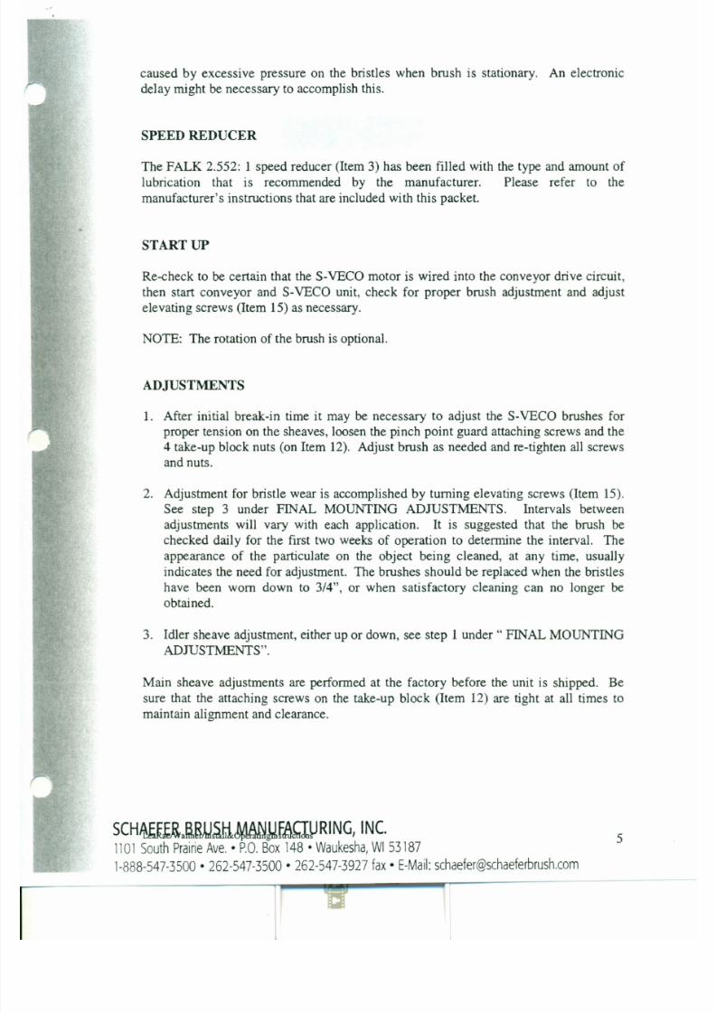
7/30/2019 MANUAL DE USUARIO GRANALLADORA (2).pdf
http://slidepdf.com/reader/full/manual-de-usuario-granalladora-2pdf 212/240
Re-check to be certain that the S-VECO motor is wired into the conveyor drive circuit,
then start conveyor and S-VECO unit, check for proper brush adjustment and adjust
elevating screws (Item 15) as necessary.
NOTE: The rotation of the brush is optional.
ADJUSTMENTS
1. After initial break-in time it may be necessary to adjust the S-VECO brushes forproper tension on the sheaves, loosen the pinch point guard attaching screws and the
4 take-up block nuts (on Item 12). Adjust brush as needed and re-tighten all screws
and nuts.
CAUTION!
Brush belts must not be over-tightened. These belts do not transmit any power.
NOTE: Over-tightening will cause the drive components to fail.
The brush adjustment clutch which is located on the brush adjustment device (Item 10
or 11 on drawing RNIHD-D-A) has a factory pre-set torque load. When the brush is
adjusted to the proper torque the clutch will break free and the handle will spin free.
7/30/2019 MANUAL DE USUARIO GRANALLADORA (2).pdf
http://slidepdf.com/reader/full/manual-de-usuario-granalladora-2pdf 213/240
DO NOT change the torque pre-set in the clutch assembly! Contact Schaefer Brush
Product Engineering @ 1-888-547-3500.
Replacement parts and brushes can be obtained by calling your local distributor.
Limited Warranty
Schaefer Brush Manufactwing Company Incorporated (the Company) warrantsthat all S-Veco linear brushing machines shall be free from defects in Schaefer
Brush workmanship and materials for a period of six (6) months from the date of
shipment from the Company.

7/30/2019 MANUAL DE USUARIO GRANALLADORA (2).pdf
http://slidepdf.com/reader/full/manual-de-usuario-granalladora-2pdf 214/240
Excluded from this warranty will be bearings and brushes, which are considered
wear items and are therefore replaceable maintenance items, and purchased
components such as motors, drives, and any electronic or mechanical devices that
are not manufactured by the Company.
If a Schaefer Brush Mfg. C O 'TInc. pr.oduct is defective due to Schaefer Brush Mfg.
Co., Inc. workmanship or materials, and the defect occurs during the warranty
period, then Schaefer Brush Mfg. Co., Inc. will either repair or replace the product,
which ever Schaefer Brush Mfg. Co., Inc. believes- to be appropriate under thecircumstances. Schaefer Brush Mfg. -Co., Inc. is not-responsible for removal "Or
shipping of the product to the company, the reinstallation of the product upon its
return to the customer, or any incidental or consequential damages, resulting from
TROUBLESHOOTING GUIDE - S-VECO LINEAR CLEANERS
PROBLEM PROBABLE CAUSE REMEDY
Conveyor not being cleaned. r Cleaner not operating. Start cleaner. Check drive
belt for slippage or breakage.
2. Brush not contacting Adjust elevating screws.3. Brush worn beyond Replace S-VECO brush.
effective cleaning point.
Conveyor not being cleaned r . Brush not contoured to belt. Adjust idler sheaves.
across entire surface. 2. Conveyor belt grooved. Check skirtboarding, return
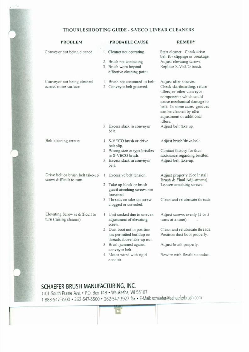
7/30/2019 MANUAL DE USUARIO GRANALLADORA (2).pdf
http://slidepdf.com/reader/full/manual-de-usuario-granalladora-2pdf 215/240
idlers, or other conveyor
components which could
cause mechanical damage to
belt. In some cases, grooves
can be cleaned by idler
adjustment or additional
idlers.~
Excess slack in conveyor Adjust belt take up..
belt.
Belt cleaning erratic. r S-VECO brush or drive Adjust brush/drive be...
belt slip.2. Wrong size or type bristles Contact factory for their
in S-VECO brush. assistance regarding bristles
3. Excess slack in conveyor Adjust belt take-up.
belt.
IN STA L L A TIO N A N D R EMO VA L IN STR UC TIO NS FO R
B·LOOM L OC K IN G A SSEMB LY SER IES 81 06 & 8103
Thank you for purchasing a B-LOCTM Keyless Frictional Locking Device.
~-LOCTt. keyless connectors provide a high capacity, zero-backlash
afVhub or coupling connection by means of a mechanical interference
'. • Please follow these INSTALLATION AND REMOVAL INSTRUCTiONS
carefully to ensure proper performance of this B-LOCTM unit.
When installing or removing B-LOC''' products, always adhere tothe following
safety standards:
1. 8e sure that all power switches are locked out before installing or removing
B-LOC'M products.
2. Eye protection is required when installing or removing B-LOC'M products
. please wear safety glasses and protective clothing.
INSTALLATION
(Refer to Figure 1)
B-LOCTA·Series 8103 and 8106 Locking Assemblies are supplied lightly oiled and
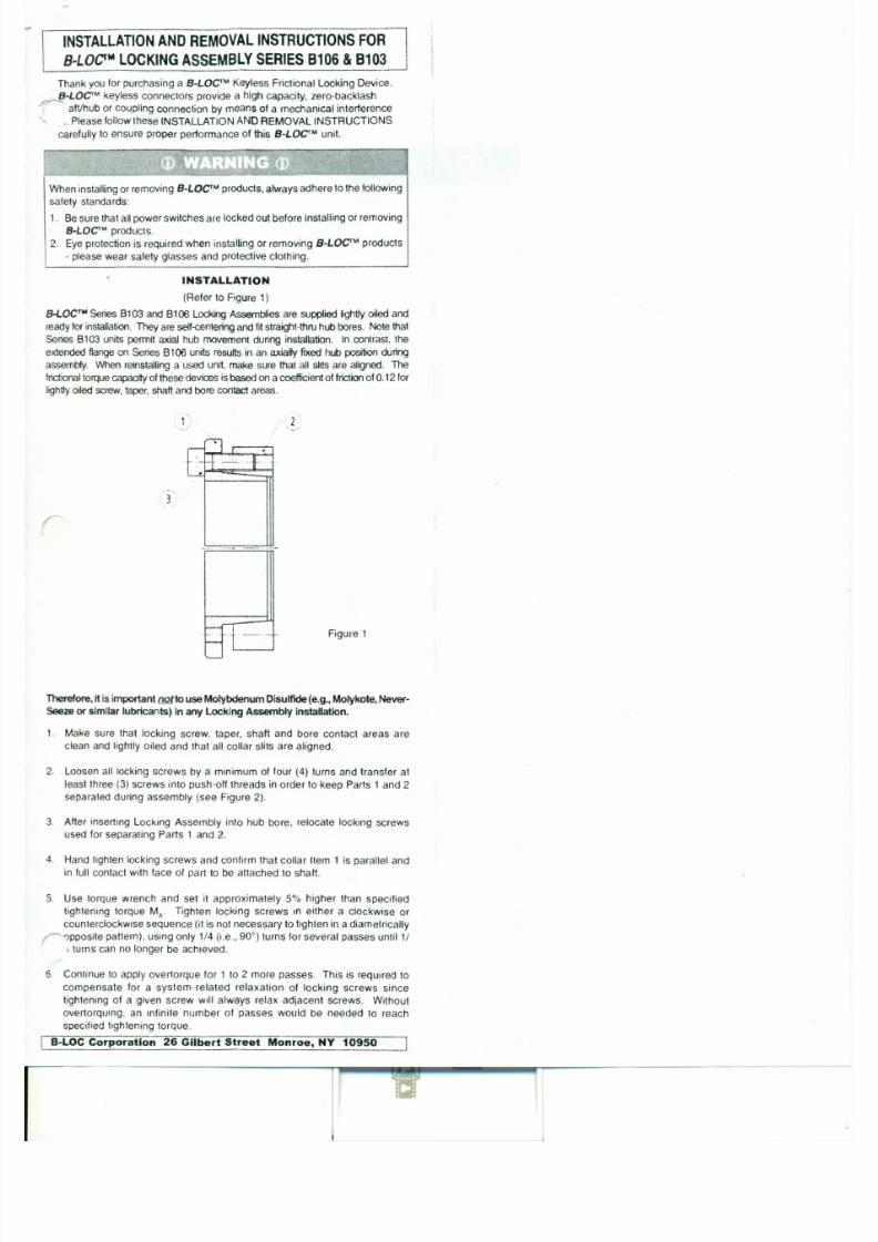
7/30/2019 MANUAL DE USUARIO GRANALLADORA (2).pdf
http://slidepdf.com/reader/full/manual-de-usuario-granalladora-2pdf 216/240
readyfor installation. They are seIf-centeringand fitstraight-thru hub bores. Note that
Series 8103 units permit axial hub movement during installation. In contrast. the
extended flange on Series 8106 units results in an axially fixed hub position during
assembly. When reinstalling a used unit, make sure that all slits are aligned. Thefrictionaltorquecapacityofthese devioes isbased on a coefficientof frictionof0.12 for
lightlyoiled screw.taper. shaft andbore contact areas.
7. Reset torque wrench to specified torque (MA) and check all locking screws.
No screw should tum at this point, otherwise repeat Step 6 for 1 or 2 more
passes. It is not necessary to re-check tightening torque after equipment hasbeen in operation.
'OTE: The torque capacity ofthese units can beincreased byapproximately 25% by
ttooroughlycleaning the shaft and Locking Assemb1y boreof any lubricant. In
applications subject to extreme corrosion, the slits in all collars should be
sealed with a suitable caulling compund or equivalent. Likewise, push-off
threads should be protected from corrosion.
INSTALLATION OF B-LOC"" LOCKING
ASSEMBLIES OVER SHAFT KEYWAYS
The Locking Assembly should be positioned so that slits in Locking Assembly
collars that contact the shaft are located approximately opposite the keyway.
In addition, a locking screw should be centered directly over the keyway.
When tigptening locking screws, it is important to foltow the installation
procedure outlined above, which specifies equal 1/4 turns of each locking
screw. Failure to follow these instructions could result in excessive tightening
of the screw over the keyway, possibly causing permanent deformation of the

7/30/2019 MANUAL DE USUARIO GRANALLADORA (2).pdf
http://slidepdf.com/reader/full/manual-de-usuario-granalladora-2pdf 217/240
Locking Assembly collars. Even after 1/4 turns can no longer be achieved, it
is important to continue to use equal turning angles for every screw until the
specified tightening torque is reached.
REMOVAL
(Refer to Figure 2)
Prior to initiating the following removal procedure, check to ensure that
no torque or thrust loads are actl"g on the Locking Assembly, shaft or
any mounted components.
IMPORTANT! Make sure ends of lockingscrews used for removal are ground flat
andare slightlychamfered to preventdamage to screw and COllarthreads during
push-off.r:
Check to ensure that axial
movement of collars - necessary
for release of connection - is not
restricted. Likewise, ensure that
push-off threads are in good
("1 \-
WHEELABRATOR
AIR FORCE 1 BLOW OFF SYSTEMS - SPARE PARTS LIST
PURCHASE ORDER # J3463012
Part# Description
AF1-WC-4 1"Wall Clamp
AF1-CC-4 1"Crossover Clamp
AF1 Stocked Parts AF1-MT60 Replacement Filter Cartridge 17.625" x 16"
AF1-FLEX-4 4" Diameter Flexible Hose
AF1-HAS-64 4" Gear Clamp SS
AF 1-AC125-4 Air Cannon Anodized, 4" Diameter Connection
Special Order PartsAF1-DCF100-61 Air Knife, 4" Diameter Double Centre Feed Connection
AF1-CF100-24 Air Knife, 4" Diameter Centre Feed Connection
AF 1-KECS20-CW Replacement Blower Wheel 13" x4" x 1-5/8" CW Rotation Coated Steel

7/30/2019 MANUAL DE USUARIO GRANALLADORA (2).pdf
http://slidepdf.com/reader/full/manual-de-usuario-granalladora-2pdf 218/240
Air Force 1 Blow Off Systems Inc.
AIR FORCE 1
BLOW OFF5
Chemical Composition Limits per ASTM B 26-98
Si Fe Cu Mn Mg Ti Other AI

7/30/2019 MANUAL DE USUARIO GRANALLADORA (2).pdf
http://slidepdf.com/reader/full/manual-de-usuario-granalladora-2pdf 219/240
0.2 0.15 0.05 0.10-0.25 6.2-7.5 0.01-0.25 0.15 Remainder
Typical Mechanical Propert iesTemper Ultimate Yield Elongation Shear Compressive Brine)) Endurance
Strength Strength Strength Yield Strength Hardness Limit
(ksi) (ksi) (% in 2 in.) (ksi) (ksi) (ksi)
F 40 20 13 27.45 24 70 10
(35 min.) (18min.) (9 min.) (70 min.) ASTM B26-98
• Thermal Conductivity (@ 77F, SI unites): 0.24 cal/cm*s*K• Heat Treatment - Achieves its physical and mechanical properties as-cast (F).
This eliminates the time and cost of heat treating.
• Machinability - Excellent Machinablility as-cast, excellent surface finish, and high demensional stability.
Corrosion Resistance - Highest of any cast alloy.
AIR FORCE 1
BLOW OFF SYSTEMS INC.
Blow Off System Installation/Operation/MaintenanceThe following general information has been prepared toassist you in installing, operating and maintaining yourAir Force 1Blow Off System. By following theinstructions, you will prolong the life of the equipment
HANDLING
Blowers should be handled carefully and lifted only bylifting eyes in larger blowers, lifting holes or by the base

7/30/2019 MANUAL DE USUARIO GRANALLADORA (2).pdf
http://slidepdf.com/reader/full/manual-de-usuario-granalladora-2pdf 220/240
and enhance performance while preventing unexpecteddown time.
The scope of this manual covers our standardarrangement 4 (direct drive) product line and is notintended to cover specially engineered equipment.
AF1-FRP SERIES BLOWERS
Lowmaintenance direct drive, FRP housing and powdercoated steel motor base includes reverse inlet venturi.
Inletair temperature is not to exceed 160° F (72°C).
SILENCERIINLET GUARD
Powder coated acoustically lined casing with drumdesign inlet guard. Includes stainless steel mountingbracket and hardware.
SILENCER/FIL TER
on smaller units. Nc. .'.1 by the shaft, motor, silencercasing or housinq. P:ecauuon should be taken to avoiddropping orjarring equipment as this can cause damageto motor shaft or wheel which may not be visible butwhich can result invibrations.
INSTALLATION
Blower wheels are dynamically balanced whenfabricated. Complete fans are test run at operatingspeeds (3600rpm motors) to check entire assembly forconformance to vibration limits. Ductwork feedingblower or on discharge side of blower should be
independently supported.
Lifting holes are provided on the motor and blower motorbase to assist in handling the fan assembly.
Fans and motors should be mounted on structurally
3) Motor - Check electrical wiring to motor. The
current characteristics of the supply line must agree
with the motor nameplate ratings. Motor should be
wired in accordance with all national and local
electric codes. All motors are ULlCSA certified.
Typical wiring is Delta Run.
4) Duct/Flex Hose Connection - Hard line duct should
never be supported by fan only. Rigid/Spiral hardline duct connections should be sealed to prevent air
leaks. To minimize sound resonating through duct,
connect rigid duct to blower inlet/outlet by means of
•flex hose/rubber connection. There should be a
minimum of three duct diameters of straight duct
prior to any elbows or transitions into or from the
blower inlet and outlet.
ELECTRICAL DISCONNECTS
Every motor driven fan should have an independent
disconnect switch to isolate the unit from electrical
supply. It should be near the fan and must be capable of
being locked out during maintenance and servicing.
NOTES:
Check amperage draw of system to motor rating (seemotor plate F.L.A.) when distribution plenum, duct, Air
Cannons and/or Air Knives have been installed and
connected. Opening dampers and/or opening Air Knife
slots will increase the impact of the nozzles, but will
increase the amperage used by the blower's motor.
Adding additional Air Knives and Air Cannons will also
7/30/2019 MANUAL DE USUARIO GRANALLADORA (2).pdf
http://slidepdf.com/reader/full/manual-de-usuario-granalladora-2pdf 221/240
5) Install blower inlet duct, inlet guard or filter.
TO ENSURE PERSONNEL OR PROPERTY
PROTECTION, DO NOT OPERATE BLOWER
WITHOUT AN INLET GUARD.
STARTUP
r:
1) Check to make sure no objects have fallen into fan
housing.
2) Start and stop the motor for a second to check
proper wheel rotation. Arrow on fan housing
indicates the proper direction of wheel rotation.Listen for anything unusual such as vibration,
rubbing or banging that may indicate a problem such
as an object in the duct or fan housing.
3) Fan may now be brought up to speed Again, listen
increase the amperage used by the blower's motor.
MAINTENANCE
1) Weekly, check inlet guards and/or filters for any
signs of restriction due to such things as dirt. In
most cases, 3 drop in amperes will be noticed as the
restrictions increase.
2) Weekly, check the condition ot any hose and replace
any that have holes or are worn.
3) Lubricate larger motors with grease at least every
3000 hours of use - more often if in harshenvironments.
*****VERY IMPORTANT*****
Every 8-10 weeks: check/tighten motor 1710' intino
AIR FORCE 1
BLOW OFF SYSTEMS INC.
B lo w O f f Sy st e m In s t a l l a t i o n /O p e r a t i o n /Ma in t e n a n c e
RECOMMENDED AF1 SAFETY PRACTICES
7/30/2019 MANUAL DE USUARIO GRANALLADORA (2).pdf
http://slidepdf.com/reader/full/manual-de-usuario-granalladora-2pdf 222/240
1. Comply with all regional and company requlations, such as AMCA and OSHA requlauo: I.:> "uvenng air
movement devices. AF1 explicitly disclaim responsibility for compliance of the systems in which our products
are components with local, national safety or electrical codes (this being outside our control).
2. 8e certain that the appropriate guard assembly for all exposed moving parts is securely in place prior to and
during use.
3. The safe operation of the AF1 blower is dependent upon proper installation, regu:., i,,~_0ctJ n and
maintenance including any system related associated components, such as filters.
4. The system supplier and or installer must consider the inclusion of necessary guord.., fa, < : : ;; ' J and oil exposed
fan related moving parts and a warning of high-velocity air streams.
5. Do not use the blower if damage is evident or suspected.
6. Always read the equipment operator's manual before use.
7. Ensure that the blower impeller is properly secured on the appropriate sized motor shaft and adequate
clearance is maintained between the impeller and blower housing.
8. Do not exceed maximum operation speed (RPM) and full load amperes (FLA) marked on the blower motor.
9. Always use OSHA approved ear and eye protection when blower is operating.
10. Inspect the blower and impeller regularly for signs of fatigue or vibration.
11. Do not operate the fan in temperatures in access of 160°F unless designed to do so and authorized in writing
'" '~' .L " lF 1 .
r:
AIR FORCE 1
BLOW OFF SYSTEMS INC.
• Excellent chemicalresistance
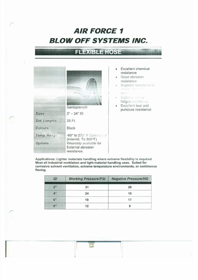
7/30/2019 MANUAL DE USUARIO GRANALLADORA (2).pdf
http://slidepdf.com/reader/full/manual-de-usuario-granalladora-2pdf 223/240
.,... w'-
• SUPSl.~! ..~
fatigue r " ; : ,; 3 U : , , .c ..,
• Excellent tear andpuncture resistance
antoprene®
2"-24"IDizes
Std. Lengths 25 Ft.
Colours Black
• Good abrasionresistance
• Superior resistance to
Installation, Operation and
Maintenance Instructions
for AC Induction Motors56- 6800 Frames (NEMA)
63 - 280 Frames (IEC)

7/30/2019 MANUAL DE USUARIO GRANALLADORA (2).pdf
http://slidepdf.com/reader/full/manual-de-usuario-granalladora-2pdf 224/240
_ . . . . . D N @IIEiiII-IEii1II.::-rllm··~1I1II.::
A REGAL-BELOIT COMPANY
MARATHON ELECTRIC
i INSTALLER: PLEASE LEAVE THIS MANUAL FOR THE OWNER'S USE
I OWNER: READ AND SAVE THESE INSTRUCTIONS
SAFETY INSTRUCTIONS
7/30/2019 MANUAL DE USUARIO GRANALLADORA (2).pdf
http://slidepdf.com/reader/full/manual-de-usuario-granalladora-2pdf 225/240
A This is the safety alert symbol. It is used to alert you to potential personal
injury hazards. Obey all safety messages that follow this symbol to avoidpossible injury or death.
A WARNING
Before installing, using, or servrcmq this product, carefully read and fully
understand the instructions including all warnings, cautions, & safety notice
statements. To reduce risk of personal injury, death and/or property damage,
fol low all inst ructions for proper motor instal lat ion , operat ion and maintenance.
These instructions are not intended as a complete listing of all details for
instal lat ion, operat ion, and maintenance. If you have any questions concerning
any of the procedures, STOP, and call the appropriate Regal-Beloit motor
company.
4.1.1 Ventilation
4.1.2 Insulation
4.1.3 Electrical Connections
4.2 Lubrication and Bearings4.2.1 Grease Type
4.2.2 Bearing Operating Temperature
4.2.3 Lubrication Interval
4.2.4 Lubrication Procedure
4.2.5 Lubrication Example
4.3 Trouble Shooting4.3.1 General Trouble-Shooting Warnings
4.3.2 Trouble-Shooting Cause / Corrective Action
1.0 INSTALLER/OWNER/OPERATOR RESPONSIBILITY:
1.1 ELECTRICAL SAFETY
A WARNING: ELECTRICAL SHOCK HAZARD
Electrical connections shall be made by a qualified electrical personnel in
accordance with all applicable codes, ordinances and sound practices.
Failure to follow these instructions could result in serious personal injury,
death and/or property damage. Only qualified personnel who are familiar
with the applicable National Code (USA = NEC) and local codes should
install or repair electrical motors and their accessories.
motor is suitable for use on Pulse Width Modulated (PWM) type VFD
power. In addition, the nameplate must be marked with the inverter
rating; for example, "2:1 CT", "2 to 1 Constant Torque", etc.
2.0 RECEIVING AND INSPECTION
2.1 INITIAL INSPECTIONS
2.1.1 CHECK PACKING LIST AND INSPECT the
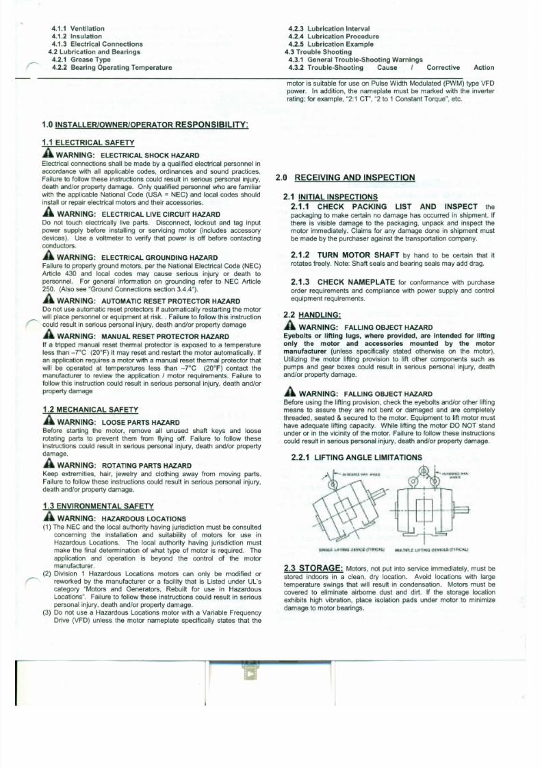
7/30/2019 MANUAL DE USUARIO GRANALLADORA (2).pdf
http://slidepdf.com/reader/full/manual-de-usuario-granalladora-2pdf 226/240
A WARNING: ELECTRICAL LIVE CIRCUIT HAZARD
Do not touch electrically live parts. Disconnect, lockout and tag input
power supply before installing or servicing motor (includes accessorydevices). Use a voltmeter to verify that power is off before contacting
conductors.
A WARNING: ELECTRICAL GROUNDING HAZARD
Failure to properly ground motors, per the National Electrical Code (NEC)
Article 430 and local codes may cause serious injury or death to
personnel. For general information on grounding refer to NEC Article
250. (Also see "Ground Connections section 3.4.4").
A WARNING: AUTOMATIC RESET PROTECTOR HAZARD
Do not use automatic reset protectors if automatically restarting the motor
will place personnel or equipment at risk .. Failure to follow this instruction
could result in serious personal injury, death and/or property damage
A WARNING: MANUAL RESET PROTECTOR HAZARD
If a tripped manual reset thermal protector is exposed to a temperature
less than -rc (20°F) it may reset and restart the motor automatically. If
an application requires a motor with a manual reset thermal protector that
will be operated at temperatures less than -rc (20°F) contact the
packaging to make certain no damage has occurred in shipment. If
there is visible damage to the packaging, unpack and inspect the
motor immediately. Claims for any damage done in shipment mustbe made by the purchaser against the transportation company.
2.1.2 TURN MOTOR SHAFT by hand to be certain that it
rotates freely. Note: Shaft seals and bearing seals may add drag.
2.1.3 CHECK NAMEPLATE for conformance with purchase
order requirements and compliance with power supply and control
equipment requirements.
2.2 HANDLING:
A WARNING: FALLING OBJECT HAZARD
Eyebolts or lifting lugs, where provided, are intended for lifting
only the motor and accessories mounted by the motor
manufacturer (unless specifically stated otherwise on the motor).
Utilizing the motor lifting provision to lift other components such as
pumps and gear boxes could result in serious personal injury, death
2.3.1 BEARING LUBRICATION: Bearings are grease packed
at the factory; relubrication upon receipt of motor or while in storage
is not necessary. If stored more than one year, add grease per
lubrication instructions (Table 4-4) before start-up.
2.3.2 SHAFT ROTATION: It is recommended that the motor
shaft be rotated 5 to 10 rotations every three months to distribute the
grease in the bearings. This will reduce the chance for corrosion to
form on the bearing rolling elements and raceways. Note: Shaft
seals and bearing seals may add drag.
2.3.3 DAMP OR HUMID STORAGE LOCATIONS: Treat
unpainted flanges, shafts, and fittings with a rust inhibitor. Apply
appropriate power to the motor's space heaters (if so equipped)
3.0 INSTALLATION AND OPERATION
A WARNING: Only qualified personnel who are familiar with the
appropriate national code, local codes and sound practices should install
TEFC (Totally Enclosed Fan Cooled) motors must meet a
minimum distance of Y, the shaft height between the fan guard
grill openings and the nearest obstruction.
3.1.3.3 HAZARDOUS LOCATIONS MOTORS: Hazardous
Locations motors are intended for installations in accordance with ~
NEC Article 500. For all installations involving Hazardous
Locations motors, consult the applicable national codes, local
codes, and the authority having jurisdiction.
Division 1 Installations - includes Class I & II: Use only
motors that are UL Listed and CSA Certified or UL Listed and
UL Certified for Canada. These motors bear a separate
nameplate that includes the UL Listing Mark and CSA
Certification Mark or includes the UL Listing Mark and the UL
Mark for Canada. This plate also bears the phrase: " Electricmotor for Hazardous Locations" and is marked with the Class,
Group and Operating Temperature Code.
Division 2 Installations - Class I only: Use only motors that
are CSA Certified and bear the CSA Certification Mark.
These motors include a phrase on the main motor nameplate
that indicates the motor is CSA Certified for Class I, Division 2
/ Zone 2 locations.
Division 2 Installation - Class II only: Use only Class II
motors as described above under "Division I Installations".
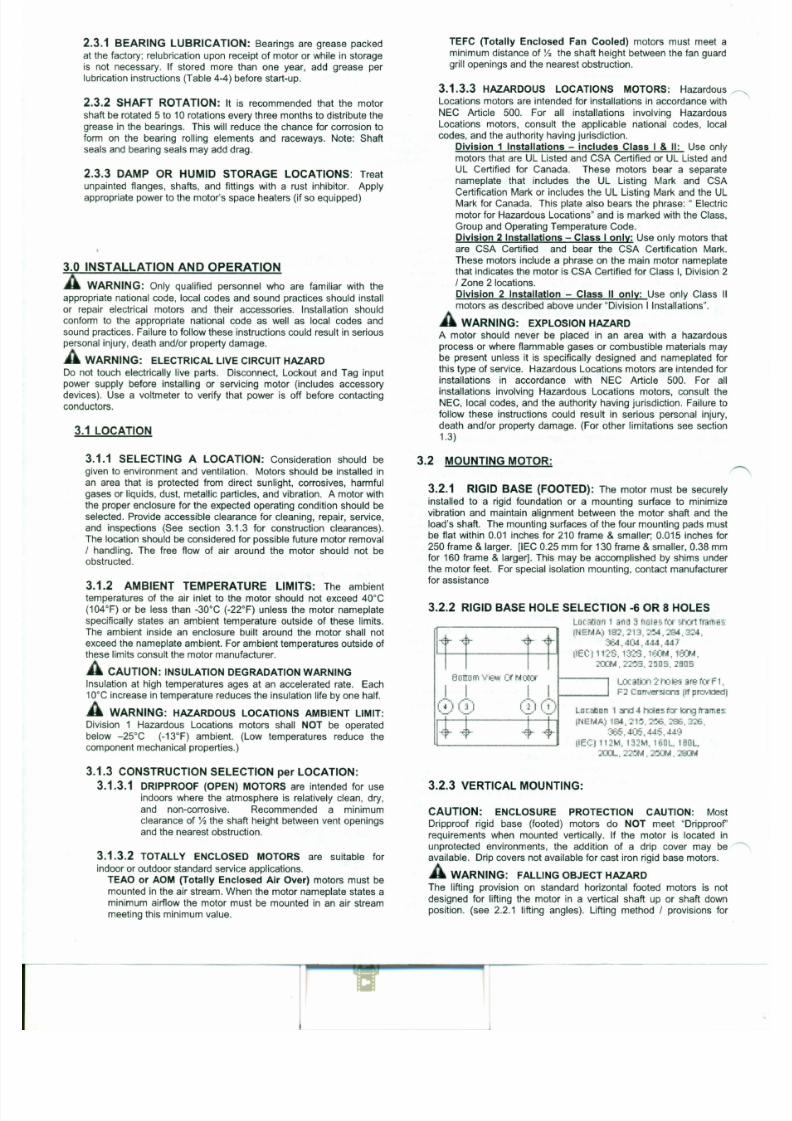
7/30/2019 MANUAL DE USUARIO GRANALLADORA (2).pdf
http://slidepdf.com/reader/full/manual-de-usuario-granalladora-2pdf 227/240
or repair electrical motors and their accessories. Installation should
conform to the appropriate national code as well as local codes and
sound practices. Failure to follow these instructions could result in seriouspersonal injury, death and/or property damage.
A WARNING: ELECTRICAL LIVE CIRCUIT HAZARD
Do not touch electrically live parts. Disconnect, Lockout and Tag input
power supply before installing or servicing motor (includes accessory
devices). Use a voltmeter to verify that power is off before contacting
conductors.
3.1 LOCATION
3.1.1 SELECTING A LOCATION: Consideration should be
given to environment and ventilation. Motors should be installed inan area that is protected from direct sunlight, corrosives, harmful
gases or liquids, dust, metallic particles, and vibration. A motor with
the proper enclosure for the expected operating condition should be
selected. Provide accessible clearance for cleaning, repair, service,
and inspections (See section 3.1.3 for construction clearances).
The location should be considered for possible future motor removal
A WARNING: EXPLOSION HAZARD
A motor should never be placed in an area with a hazardousprocess or where flammable gases or combustible materials may
be present unless it is specifically designed and nameplated for
this type of service. Hazardous Locations motors are intended for
installations in accordance with NEC Article 500. For all
installations involving Hazardous Locations motors, consult the
NEC, local codes, and the authority having jurisdiction. Failure to
follow these instructions could result in serious personal injury,
death and/or property damage. (For other limitations see section
1.3)
3.2 MOUNTING MOTOR:
3.2.1 RIGID BASE (FOOTED): The motor must be securely
installed to a rigid foundation or a mounting surface to minimize
vibration and maintain alignment between the motor shaft and the
load's shaft. The mounting surfaces of the four mounting pads must
be flat within 0.01 inches for 210 frame & smaller; 0.015 inches for
Figure 1 3.3.4.4 Bel t Tension
ACAUTION: Equ ipment Fai lu re Caut ion
Belt tensioning by feel is NOT acceptable. Tensioning by "feel" can ~
be very misleading, and can damage motor and equipment.
It is normal for V-belts to squeal initially when line starting a motor.
In general, belt tensions should be kept as loose as possible while
still transmitting the required torque without slipping. Belt tensions
must be measured with a belt tension gage. These inexpensive
gages may be obtained through belt manufacturers, or distributors.
Shaft RPM x 3.14 x Sheave Dia (inches)BELT SPEED (Ft lmin) =-----------
12
Proper belt tension is determined by measuring the force required to
deflect the center of the belt a given distance. The proper deflection(in inches) is determined by dividing the belt span in inches by 64.
Calculate the proper deflection and then see Table 3-3 for the
required "Deflected Force" to achieve that deflection.
After tensioning the belt, rotate the sheaves for several rotations or
operate the system for a few minutes to seat belts into the grooves,
then re-tension the belts. New belts will stretch during use, and
should be retensioned after the first eight hours of use.
3.~.4.2 Number of Belts
In general, use the fewest number of belts that will transmit the
required torque without slipping. See Table 3-3 for recommended
maximum number of belts. Each belt adds to the tension in the
system, which increases load on the shafts and bearings. Belts are
most efficient when operated at or near their rated horsepower.
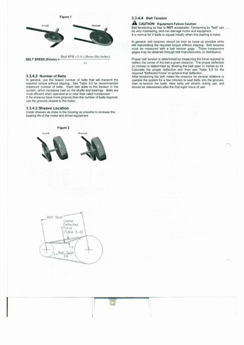
7/30/2019 MANUAL DE USUARIO GRANALLADORA (2).pdf
http://slidepdf.com/reader/full/manual-de-usuario-granalladora-2pdf 228/240
If the sheaves have more grooves than the number of belts required,
use the grooves closest to the motor.
3.3.4.3 Sheave Locat ionInstall sheaves as close to the housing as possible to increase the
bearing life of the motor and driven equipment
Fi gu re 2
Avoid Desired
Figure 1 3.3.4.4 Belt Tensi on
ACAUTION: Equ ipmen t Fai lu re Cau ti on
Belt tensioning by feel is NOT acceptable. Tensioning by "feel" can ~
be very misleading, and can damage motor and equipment.
It is normal for V-belts to squeal initially when line starting a motor.
In general, belt tensions should be kept as loose as possible while
still transmitting the required torque without slipping. Belt tensions
must be measured with a belt tension gage. These inexpensive
gages may be obtained through belt manufacturers, or distributors.
Shaft RPM x 3.14 x Sheave Dia (inches)BELT SPEED (Ftlmin) =------------
12
Proper belt tension is determined by measuring the force required to
deflect the center of the belt a given distance. The proper deflection(in inches) is determined by dividing the belt span in inches by 64.
Calculate the proper deflection and then see Table 3-3 for the
required "Deflected Force" to achieve that deflection.
After tensioning the belt, rotate the sheaves for several rotations or
operate the system for a few minutes to seat belts into the grooves,
then re-tension the belts. New belts will stretch during use, and
should be retensioned after the first eight hours of use.
3.~.4.2 Number of Belts
In general, use the fewest number of belts that will transmit the
required torque without slipping. See Table 3-3 for recommended
maximum number of belts. Each belt adds to the tension in the
system, which increases load on the shafts and bearings. Belts are
most efficient when operated at or near their rated horsepower.

7/30/2019 MANUAL DE USUARIO GRANALLADORA (2).pdf
http://slidepdf.com/reader/full/manual-de-usuario-granalladora-2pdf 229/240
If the sheaves have more grooves than the number of belts required,
use the grooves closest to the motor.
3.3.4.3 Sheave LocationInstall sheaves as close to the housing as possible to increase the
bearing life of the motor and driven equipment
Fi gu re 2
Avoid Desired
Table 3-3 Recommended Minimum Sheave Diameters, Belt vpe, um er 0 e ts an e ecte orce
1200 rpm 1S00 rpm 3600 rpmMin Max Avg. Min Max Avg. Min Max Avg.
Sheave # Deflected Sheave # Deflected Sheave # Deflected
Dia (in) Belt of Force Dia (in) Belt of Force Dia (in) Belt of ForceMotor Hp Tvpe Belts (lbs) Tvpe Belts (ibs) Type Belts (Ibs)
('\ -r c
"" ""'V . " . "" ""'V ."" ""
"\IV . ."1 2.4 3VX 1 4.0 2.2 3VX 1 3.1 2.2 3VX 1 1.6
1.5 2.4 3VX 2 3.1 2.4 3VX 2 2.1 2.2 3VX 1 2.5
2 2.4 3VX 3 2.8 2.4 3VX 2 2.9 2.4 3VX 1 2.7
3 3.0 3VX 2 3.3 2.4 3VX 3 2.9 2.4 3VX 2 2.3
5 3.0 3VX 3 4.0 3.0 3VX 3 3.7 2.4 3VX 3 2.5
7.5 3.8 3VX 4 4.7 3.0 3VX 4 4.1 3.0 3VX 2 4.2
10 4.4 3VX 4 5.4 3.8 3VX 4 4.3 3.0 3VX 3 3.815 4.4 3VX 5 5.4 4.4 3VX 4 5.4 3.8 3VX 3 4.4
20 5.2 3VX 6 ·6.0 4.4 3VX 6 4.8 4.4 3VX 3 5.0
25 6.0 3VX 7 5.6 4.4 3VX 7 5.2 4.4 3VX 4 4.71n F ; R '>,\1)( 7 <; Q <; ? '>,\1)( 7 <;'>,
40 6.8 5VX 4 11.6 6.0 3VX 7 6.0
50 8.2 5VX 4 14.6 6.8 3VX 8 5.9
60 8.2 5VX 5 14.1 7.4 5VX 4 13.3
75 10.0 5VX 5 14.5 8.6 5VX 4 14.3
Contact Motor00 10.0 5VX 6 16.0 8.6 5VX 6 13
T N b f B I d D fl d F
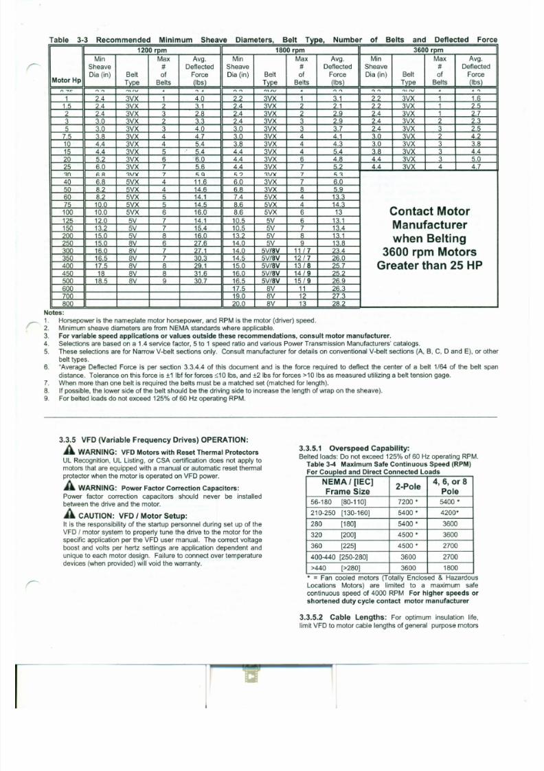
7/30/2019 MANUAL DE USUARIO GRANALLADORA (2).pdf
http://slidepdf.com/reader/full/manual-de-usuario-granalladora-2pdf 230/240
125 12.0 5V 7 14.1 10.5 5V 6 13.1Manufacturer50 13.2 5V 7 15.4 10.5 5V 7 13.4
200 15.0 5V 8 16.0 13.2 5V 8 13.1 when Belting250 15.0 8V 6 27.6 14.0 5V 9 13.8
300 16.0 8V 7 27.1 14.0 5V/SV 11 1 7 23.4 3600 rpm Motors350 16.5 8V 7 30.3 14.5 5V/SV 12/7 26.0
400 17.5 8V 8 29.1 15.0 5V/SV 13/S 25.7 Greater than 25 HP450 18 8V 8 31.6 16.0 5V/SV 14/9 25.2
500 18.5 8V 9 30.7 16.5 5V/SV 15 /9 26.9
600 17.5 8V 11 26.3
700 19.0 8V 12 27.3
800 20.0 8V 13 28.2
Notes:
1. Horsepower is the nameplate motor horsepower, and RPM is the motor (driver) speed.2. Minimum sheave diameters are from NEMA standards where applicable.
3. For variable speed applications or values outside these recommendations, consult motor manufacturer.
4. Selections are based on a 1.4 service factor, 5 to 1 speed ratio and various Power Transmission Manufacturers' catalogs.
5. These selections are for Narrow V-belt sections only. Consult manufacturer for details on conventional V-belt sections (A, B, C, D and E), or other
belt types.
6. "Average Deflected Force is per section 3.3.4.4 of this document and is the force required to deflect the center of a belt 1/ 64 of the belt span
to Table 3-5 values. Definite purpose VFD motors may
accommodate longer cable lengths. For additional
information contact motor manufacturer.
Table 3-5 Max Cable Lengths General Purpose MotorsThese values are based on 3 kHz carrier frequency. Add
suitable VFD output-side filters when exceeding the listed
values
Frame Size 230V 460 V 575 V
NEMA56-320 600 ft. 125 ft. 40 ft.
NEMA 360-5011 1000 ft. 225 ft. 60 ft.
IEC 80-200 180 m. 40m. 12 m.
IEC 225-280. 300m. 70m. 18 m.
3.3.5.3 VFD Grounding: Equipment grounding conductors
may be run in the same conduit as the AC motor power leads.
This wire must be used as the equipment ground for the motor and
not as the fourth current carrying wire of a "WYE" motor circuit.
The grounded metal conduit carrying the output power conductors
can provide EMI shielding, but the conduit does not provide an
adequate ground for the motor; a separate grounding conductor
must be used. Grounding the motor neutral (WYE) of a VFD
General Information: When thermal protection is provided, one of
the following will be stamped on the nameplate:
1. "THERMALLY PROTECTED" This motor has built in thermal
protection. Thermal protectors open the motor circuitelectrically when the motor overheats or is overloaded. The ~
protector cannot be reset until the motor cools. If the
protector is automatic, it will reset itself. If the protector is
manual, disconnect motor from power supply. After protector
cools (five minutes or more) press the reset button and
reapply power to the motor. In some cases a motor is marked
"Auto" and the connection diagram on the motor will identify
T'Stat leads - see "2 "below. (See warnings on Manual and
Automatic reset protectors - section 1.1)
2. "WITH OVERHEAT PROTECTIVE DEVICE": This motor isprovided with an overheat protective device that does not
directly open the motor circuit. Motors nameplated with this
phrase have either thermostats, thermisters or RTD's. The
leads to these devices are routed into the motor conduit box
or into an auxiliary box. The lead markings are defined on the
nameplate (normally "P1", "P2") . The circuit controlled by the
overheat protection device must be limited to a maximum of
600 volts and 360 volt-amps. See connection decal provided
inside the terminal box cover. Failure to connect these over
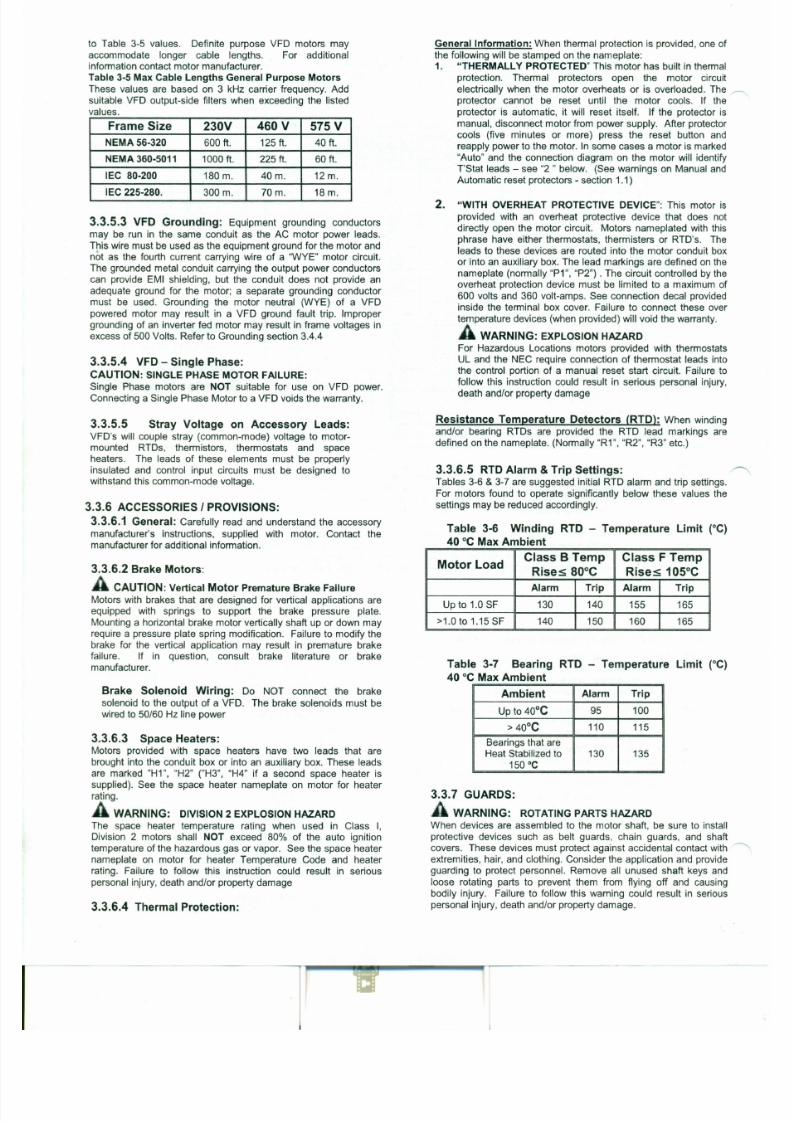
7/30/2019 MANUAL DE USUARIO GRANALLADORA (2).pdf
http://slidepdf.com/reader/full/manual-de-usuario-granalladora-2pdf 231/240
powered motor may result in a VFD ground fault trip. Improper
grounding of an inverter fed motor may result in frame voltages in
excess of 500 Volts. Refer to Grounding section 3.4.4
3.3.5.4 VFD - Single Phase:
CAUTION: SINGLE PHASE MOTOR FAILURE:
S ingle Phase motors are NOT suitable for use on VFD power.
Connecting a Single Phase Motor to a VFD voids the warranty.
3.3.5.5 Stray Voltage on Accessory Leads:
VFD's will couple stray (common-mode) voltage to motor-
mounted RTDs, thermistors, thermostats and space
heaters. The leads of these elements must be properly
insulated and control input circuits must be designed towithstand this common-mode voltage.
3.3.6 ACCESSORIES I PROVISIONS:
3.3.6.1 General: Carefully read and understand the accessory
manufacturer's instructions, supplied with motor. Contact the
temperature devices (when provided) will void the warranty.
A WARNING: EXPLOSION HAZARDFor Hazardous Locations motors provided with thermostats
UL and the NEC require connection of thermostat leads into
the control portion of a manual reset start circuit. Failure to
follow this instruction could result in serious personal injury,
death and/or property damage
Resistance Temperature Detectors (RTD): When winding
and/or bearing RTDs are provided the RTD lead markings are
defined on the nameplate. (Normally "R1", "R2", "R3" etc.)
3.3.6.5 RTD Alarm & Trip Settings: ~Tables 3-6 & 3-7 are suggested initial RTD alarm and trip settings.
For motors found to operate significantly below these values the
settings may be reduced accordingly.
Table 3-6 Winding RTD - Temperature Limit (0C)
3.4 ELECTRICAL CONNECTIONS:
A WARNING: ELECTRICAL HAZARDS
Before proceeding read Section 1-1 on Electrical Safety. Failure to
follow the instructions in Section 1-1 could result in serious personal
injury, death and/or property damage
3.4.1 POWER SUPPLY I BRANCH CIRCUIT
A WARNING: POWER SUPPLY INCOMPATIBILITY HAZARD
Check power supply to make certain that voltage, frequency and
current carrying capacity are in accordance with the motor
nameplate. Failure to match motor nameplate values could result in
serious personal injury, death and/or property damage
A WARNING: BRANCH CIRCUIT SUPPLY HAZARD
Motor and control wiring, fusing, overload protection, disconnects,
accessories and grounding must always conform to the applicable
electrical codes as well as local codes and sound practices.
3.4.1.1 Branch Circuit Supply to a motor should include a
disconnect switch, short circuit current fuse or breaker protection,
motor starter (controller) and correctly sized thermal elements or
(3) Machined Surface Gap (Hazardous Locations Terminal
Boxes): The gap between mating surfaces with the machined
terminal box MUST BE LESS THAN 0.002 inches. This gap must
be checked with a feeler gage along the entire perimeter. If there isvisible damage to the mating surfaces, or if the gap between these
surfaces exceeds 0.002 inches, DO NOT complete the installation
and contact the motor manufacturer. Failure to follow these
instructions could result in serious personal injury, death and/or
property damage
3.4.3 LEAD CONNECTIONSElectrical connections to be made per nameplate connection diagram
or separate connection plate. In making connections follow the
applicable electrical code as well as local codes and practices.
A WARNING: ELECTRICAL CONNECTION HAZARD
Failure to correctly connect the motor leads and grounding
conductor can result in injury or death. Motor lead connections can
short and cause damage or injury if not well secured and insulated.
3.4.3.1 Wire Size (Single Phase) RequirementsThe minimum wire size for Single Phase, 115 & 230 Volt Circuits
must meet table 3-8 for a given distance between motor and
either Fuse or Meter Box.
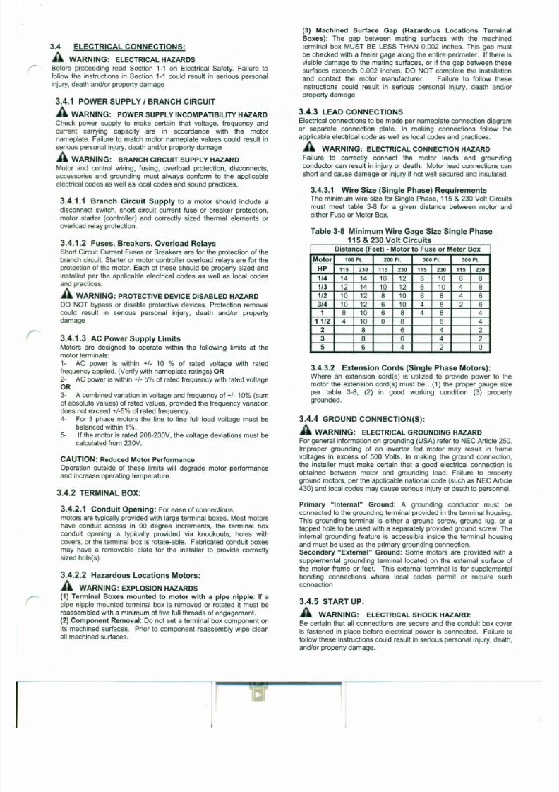
7/30/2019 MANUAL DE USUARIO GRANALLADORA (2).pdf
http://slidepdf.com/reader/full/manual-de-usuario-granalladora-2pdf 232/240
overload relay protection.
3.4.1.2 Fuses, Breakers, Overload RelaysShort Circuit Current Fuses or Breakers are for the protection of the
branch circuit. Starter or motor controller overload relays are for the
protection of the motor. Each of these should be properly sized and
installed per the applicable electrical codes as well as local codes
and practices.
A WARNING: PROTECTIVE DEVICE DISABLED HAZARD
DO NOT bypass or disable protective devices. Protection removal
could result in serious personal injury, death and/or propertydamage
3.4.1.3 AC Power Supply LimitsMotors are designed to operate within the following limits at the
motor terminals:
1- AC power is within +- 10 % of rated voltage with rated
frequency applied. (Verify with nameplate ratings) OR
2- AC power is within +- 5% of rated frequency with rated voltage
Table 3·8 Minimum Wire Gage Size Single Phase
115 & 230 Volt CircuitsDistance (Feet) - Motor to Fuse or Meter Box
Motor 100 Ft. 200 Ft. 300 Ft. 500 Ft.
HP 115 230 115 230 115 230 115 230
1/4 14 14 10 12 8 10 6 8
1/3 12 14 10 12 6 10 4 8
1/2 10 12 8 10 6 8 4 6
3/4 10 12 6 10 4 8 2 6
1 8 10 6 8 4 6 4
1 1/2 4 10 0 8 6 4
2 8 6 4 23 8 6 4 2
5 6 4 2 0
3.4.3.2 Extension Cords (Single Phase Motors):Where an extension cord(s) is utilized to provide power to the
A WARNING: LOOSE & ROTATING PARTS HAZARD
Before proceeding read Section 1-2 on Mechanical Safety. Failure to
follow the instructions in Section 1-2 could result in serious personal
injury, death and/or property damage
A WARNING: EXCESSIVE SURFACE TEMPERATURE
HAZARD
Motors with the temperature code stated on the nameplate are
designed to operate within this limit. Improper application or
operation can cause the maximum surface temperature to be
exceeded. A motor operated in a Hazardous Location that exceeds
this surface temperature limit increases the potential of ignitinghazardous materials. Therefore, motor selection, installation,
operation, and maintenance must be carefully considered to ensure
against the following conditions: (1) Motor load exceeds service
factor value, (2) Ambient temperature above nameplate value, (3)
Voltages outside of limits (3.4.1.3), (4) Loss of proper ventilation, (5)
VFD operation exceeding motor nameplate rating, (6) Altitude above
3300 feet /1000 meters, (7) Severe duty cycles, (8) Repeated starts,
(9) Motor stall, (10) Motor reversing, and (10) Single phase
operation. Failure to follow these instructions could result in serious
Do not start more than twice in succession under full load.
Repeated starts and/or jogs of induction motors can cause
overheating and immediate failure. Contact the motor manufacturer
if it is necessary to repeatedly start or jog the motor.
4.0 MAINTENANCE:
A WARNING: Hazardous Locations Motor Repair HAZARD:
Division 1 Hazardous Locations motors can only be modified or repaired
by the manufacturer or a facility that is Listed under UL's category
"Motors and Generators, Rebuilt for use in Hazardous Locations". Failure
to follow these instructions could result in serious personal injury, death
and/or property damage.
A WARNING: ELECTRICAL SHOCK HAZARD
Electrical connections are to be made by qualified electrical personnel inaccordance with all applicable codes, ordinances and sound practices.
Failure to follow these instructions could result in serious personal injury,
death and/or property damage. Only qualified personnel who are familiar
with the applicable national codes, local codes and sound practices
should install or repair electric motors and their accessories.
A WARNING: ELECTRICAL LIVE CIRCUIT HAZARD
Do not touch electrically live parts. Disconnect, lockout and tag input
power supply before installing or servicing motor (includes accessory
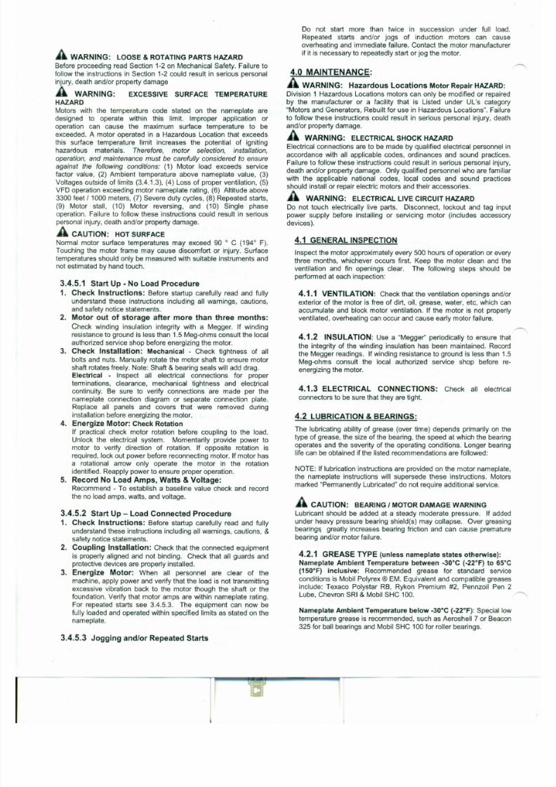
7/30/2019 MANUAL DE USUARIO GRANALLADORA (2).pdf
http://slidepdf.com/reader/full/manual-de-usuario-granalladora-2pdf 233/240
personal injury, death and/or property damage.
A CAUTION: HOT SURFACE
Normal motor surface temperatures may exceed 90 ° C (194° F).
Touching the motor frame may cause discomfort or injury. Surface
temperatures should only be measured with suitable instruments and
not estimated by hand touch.
3.4.5.1 Start Up - No Load Procedure
1. Check Instructions: Before startup carefully read and fully
understand these instructions including all warnings, cautions,
and safety notice statements.
2. Motor out of storage after more than three months:
Check winding insulation integrity with a Megger. If winding
resistance to ground is less than 1.5 Meg-ohms consult the local
authorized service shop before energizing the motor.
3. Check Installation: Mechanical - Check tightness of all
bolts and nuts. Manually rotate the motor shaft to ensure motor
shaft rotates freely. Note: Shaft & bearing seals will add drag.
Electrical - Inspect all electrical connections for proper
devices).
4.1 GENERAL INSPECTION
Inspect the motor approximately every 500 hours of operation or every
three months, whichever occurs first. Keep the motor clean and the
ventilation and fin openings clear. The following steps should be
performed at each inspection:
4.1.1 VENTILATION: Check that the ventilation openings and/or
exterior of the motor is free of dirt, oil, grease, water, etc, which can
accumulate and block motor ventilation. If the motor is not properly
ventilated, overheating can occur and cause early motor failure.
~4.1.2 INSULATION: Use a "Megger" periodically to ensure that
the integrity of the winding insulation has been maintained. Record
the Megger readings. If winding resistance to ground is less than 1.5
Meg-ohms consult the local authorized service shop before re-
energizing the motor.
Nameplate Ambient Temperature above 65°C (150°F): Dow
Corning DC44 or equivalent, a special high temperature grease is
required. Note that Dow Corning DC44 grease does not mix with
other grease types.
For RTD settings see Table 3-7.
4 . 2 . 2 BEARING OPERATING TEMPERATURE:
A CAUTION: HOT SURFACE
The external surface temperature of the end shield (bracket) bearing
hub may reach 100° C (212° F) during normal operation. Touching
this surface may cause discomfort or injury. Surface temperatures
should only be measured with suitable instruments and not estimated
by hand touch.
4 . 2 . 3 LUBRICATION INTERVALS: (For motors with regreasing provisions)
Eq.4.2 Lubrication Interval = [(Table 4-1) hrs] x [Interval Multiplier (Table 4-2)] x [Construction Multiplier (Table 4-3)]
Table 4 - 1 Lubrication Intervals (Hours) These values are based on average use.
Operating Speed - RPM (See Table 3 . 4 for Maximum Operating Speed)
NEMA I [IEC] Frame Size <7 2 0 0 <5 4 0 0 < 4 5 0 0 < 3 6 0 0 < 1 8 0 0 < 1 2 0 0
56-180 [80-110] 2500 Hrs. 4000 Hrs 5000 Hrs 6000 Hrs. 17000 Hrs. 20000 Hrs.
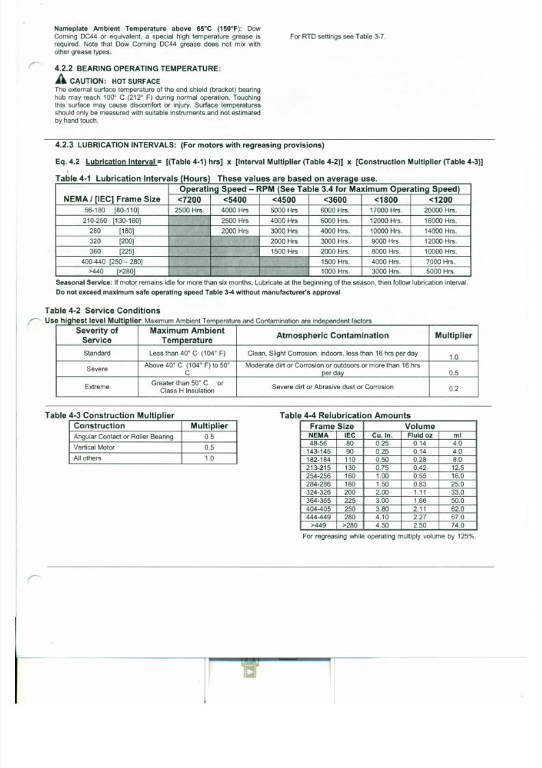
7/30/2019 MANUAL DE USUARIO GRANALLADORA (2).pdf
http://slidepdf.com/reader/full/manual-de-usuario-granalladora-2pdf 234/240
210-250 [130-160] 2500 Hrs 4000 Hrs 5000 Hrs. 12000 Hrs. 16000 Hrs.
280 [180] 2000 Hrs 3000 Hrs 4000 Hrs. 10000 Hrs. 14000 Hrs.320 [200] 2000 Hrs 3000 Hrs. 9000 Hrs. 12000 Hrs.
360 [225] 1500 Hrs 2000 Hrs. 8000 Hrs. 10000 Hrs.
400-440 [250 - 280] 1500 Hrs. 4000 Hrs. 7000 Hrs.
>440 [>280] 1000 Hrs. 3000 Hrs. 5000 Hrs.
Seasonal Service: Ifmotor remains idle for more than six months, Lubricate at the beginning of the season, then follow lubrication interval.
Do not exceed maximum safe operating speed Table 3-4 without manufacturer's approval
Table 4 - 2 Service Conditions
Use hiqhest level Multiplier: Maximum Ambient Temperature and Contamination are independent factorsSeverity of Maximum Ambient
Atmospheric Contamination MultiplierService Temperature
Standard Less than 40° C (104° F) Clean, Slight Corrosion, indoors, less than 16 hrs per day1.0
SevereAbove 40° C (104° F) to 50° Moderate dirt or Corrosion or outdoors or more than 16 hrs
4.2.4 LUBRICATION PROCEDURE:(For Motors with Regreasing Provisions)
CAUTION: BEARING DAMAGE WARNING
Added grease must be compatible with the original equipment's
grease. If a grease other than those stated in 4.2.1 is to be utilized
contact the motor manufacturer. Nameplate information
supersedes section 4.2.1 (GREASE TYPE). New grease must be
free of dirt. Failure to follow these instructions and procedure
below may result in bearing and/or motor damage.
For an extremely dirty environment, contact the motor
manufacturer for additional information.
LUBRICATION PROCEDURE:
1..Clean the grease inlet plug or zerk fittings prior to regreasing.
2. (If present) Remove grease drain plug and clear outlet hole
blockage.
CAUTION: GREASE DRAIN PLUGGED:
Old grease may completely block the drain opening and must be
1. Table 4-1 list 10,000 hours for standard conditions.
2. Table 4-2 classifies severity of service as "Severe" with a
multiplier of 0.5.
3. Table 4-3 lists a multiplier value of 0.5 for "Vertical"4. (Eq.4.2) Interval = 10,000 hrs x 0.5 x 0.5 = 2500 hrs
3
Table 4-4 shows that 1.5 in of grease is to be added.3
Relubricate every 2,500 hrs of service with 1.5 in of
recommended grease.
4.3 TROUBLE-SHOOTING
A WARNING: READ INSTRUCTIONS:
Before trouble-shooting a motor, carefully read and fully understand
the warnings, cautions, & safety notice statements in this manual.
A WARNING: Hazardous Locations Motor Repair:
Motors nameplated for use in Division 1 Hazardous Locations can
only be disassembled, modified or repaired by the plant of
manufacturer or a facility that is Listed under UL's category "Motors
and Generators, Rebuilt for use in Hazardous Locations". Failure to
follow these instructions could result in serious personal injury,
death and/or property damage
CAUTION: DISASSEMBLY APPROVAL REQUIRED:
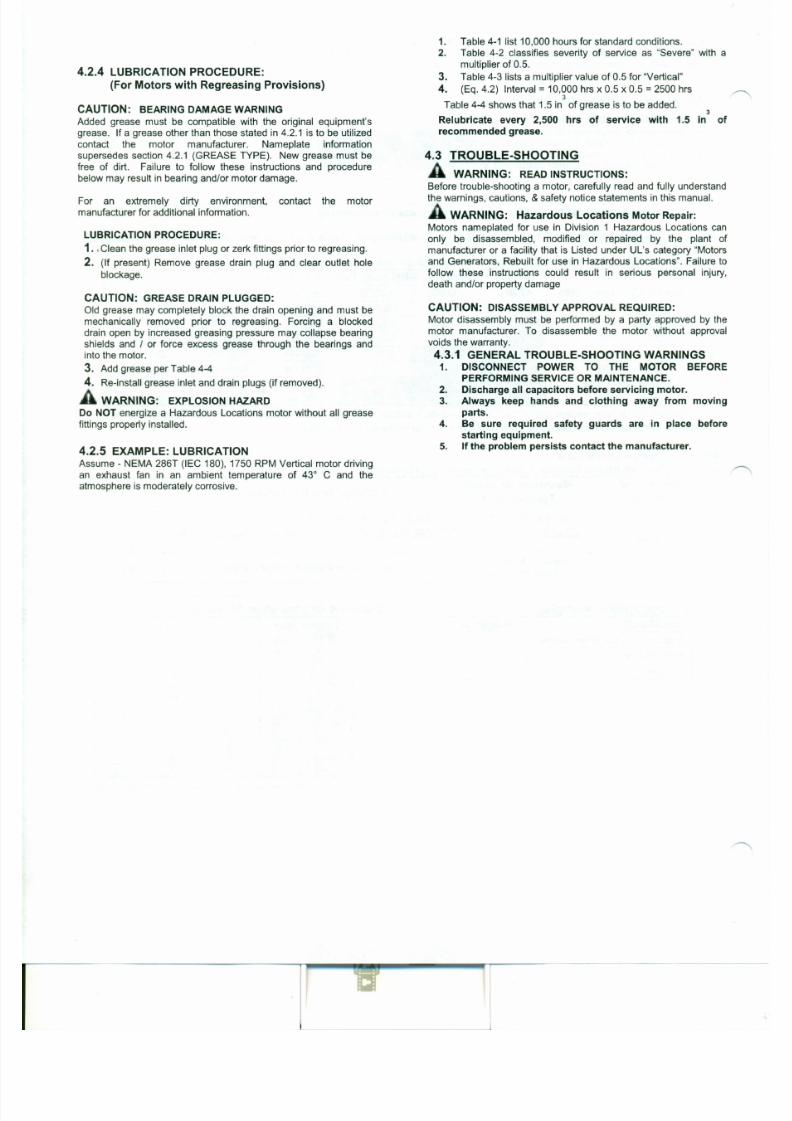
7/30/2019 MANUAL DE USUARIO GRANALLADORA (2).pdf
http://slidepdf.com/reader/full/manual-de-usuario-granalladora-2pdf 235/240
mechanically removed prior to regreasing. Forcing a blocked
drain open by increased greasing pressure may collapse bearing
shields and / or force excess grease through the bearings and
into the motor.
3. Add grease per Table 4-4
4. Re-install grease inlet and drain plugs (if removed).
A WARNING: EXPLOSION HAZARD
Do NOT energize a Hazardous Locations motor without all grease
fittings properly installed.
4.2.5 EXAMPLE: LUBRICATIONAssume - NEMA 286T (IEC 180),1750 RPM Vertical motor driving
an exhaust fan in an ambient temperature of 43° C and the
atmosphere is moderately corrosive.
Motor disassembly must be performed by a party approved by the
motor manufacturer. To disassemble the motor without approval
voids the warranty.
4.3.1 GENERAL TROUBLE-SHOOTING WARNINGS1. DISCONNECT POWER TO THE MOTOR BEFORE
PERFORMING SERVICE OR MAINTENANCE.
2. Discharge all capacitors before servicing motor.
3. Always keep hands and clothing away from moving
parts.
4. Be sure required safety guards are in place before
starting equipment.
5. If the problem persists contact the manufacturer.
432 M t T bl h t" C IC t" A t " T bl 45. o or rou e-s oOlng ause orrec rve cion - a e -Issue: Likely Cause: Corrective Action:
Motor fails to start upon init ial installat ion:
A.)Supply voltage is too low or is severely unbalanced (one (1) Check power supply fuses (2) Match motor lead wiring to nameplate connection
phase is low or missing). diagram and supply voltage (3) Ensure that steady state supply voltage at motor
terminals is within limits (see section 3.4.1.3). Correct as needed (4) Obtain correc
B.) Motor leads are miswired at conduit box. motor to match actual supply voltage.
C.) Driven load exceeds motor capacity(1) Verify that motor & load turn freely (2) Disconnect motor from load & ensure
motor turns freely. Note: Roller bearings make noise when motor is uncoupled and
D.) Load is jammed.shaft is rotated (3) Verify that motor starts when disconnected from load (4)
Remove excessive / bindinq load if present.
E.) Fan guard is bent and making contact with fan Replace fan guard & fan (if blades are damaged)
F.) VFD with power factor capacitors installed Remove power factor correction capacitors if equipped
G.) VFD with motor neutral lead grounded Ensure that motor neutral lead is ungrounded
(1) Repeat checks listed above (2) Verify that VFD current limit and starting boost
H.) VFD programmed incorrectlyare set correctly (5) Double-check motor and feedback parameter settings and
VFD permissives (6) Repeat autotune (for vector drives) procedure (7) Consult
VFD supplier.
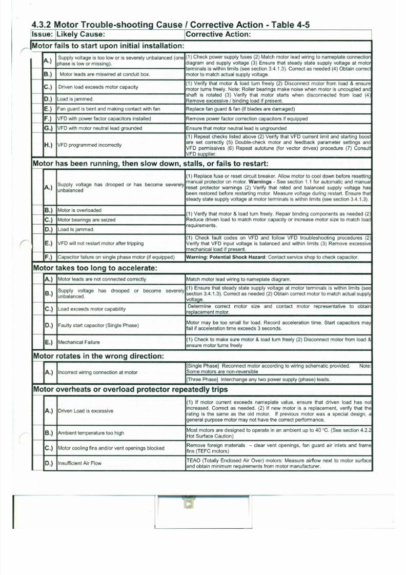
7/30/2019 MANUAL DE USUARIO GRANALLADORA (2).pdf
http://slidepdf.com/reader/full/manual-de-usuario-granalladora-2pdf 236/240
Motor has been running, then slow down, stalls, or fails to restart:
(1) Replace fuse or reset circuit breaker. Allow motor to cool down before resetting
Supply voltage has drooped or has become severelymanual protector on motor. Warning s - See section 1.1 for automatic and manual
A.)unbalanced
reset protector warnings (2) Verify that rated and balanced supply voltage has
been restored before restarting motor. Measure voltage during restart. Ensure that
steady state supply voltage at motor terminals is within limits (see section 3.4.1.3).
B.) Motor is overloaded(1) Verify that motor & load turn freely. Repair binding components as needed (2)
C.) Motor bearings are seized Reduce driven load to match motor capacity or increase motor size to match load
D.) Load Is jammed.requirements.
r:(1) Check fault codes on VFD and follow VFD troubleshooting procedures (2)
E.) VFD will not restart motor after tripping Verify that VFD input voltage is balanced and within limits (3) Remove excessive
mechanical load if present.
F.) Capacitor failure on single phase motor (if equipped) Warning: Potential Shock Hazard: Contact service shop to check capacitor.
Motor takes too long to accelerate:
E.) Motor is started too frequently See section 3.4.5.3
(1) Ensure that steady state supply voltage at motor terminals is within limits (see
F.) Supply voltage too low, too high, or unbalanced section 3.4.1.3) Correct as needed (2) Reconnect motor per input voltage (3)Obtain correct motor to match power supply.
Motor Vibrates
A.) Motor misaligned to load. Realign load
(1) Ensure that load is dynamically balanced: (2) Remove motor from load and
B.) Load out of balance (Direct drive application)inspect motor by itself. Verify that motor shaft is not bent. Rule of thumb is 0.002"
runout for shafts extension lengths up to 3.00". Add 0.0005" per every additional
inch of shaft lenoth bevond 3.00".
C.) Uneven tension on multiple belts
Mixing new with used belts. Replace multiple belt applications with a complete set
of matched belts.
(1) De-energize motor and record vibration as load coasts from 100% speed to 0
RPM. If vibration drops immediately, vibration source is electrical. If levels do no.Driven load operating at resonant point / natural drop immediately, source is mechanical (2) Redesign system to operate below the
D .)frequency. resonant point (3) On VFD-driven loads, program skip frequencies to bypass
resonant points (4) Increase carrier frequency to obtain <3% THD current (5) On
variable torque loads reduce volts/hertz below base speed.
E.) VFD torque pulsations(1) Adjust VFD to obtain <3% THD current @ rated motor current (2) Adjust VFD
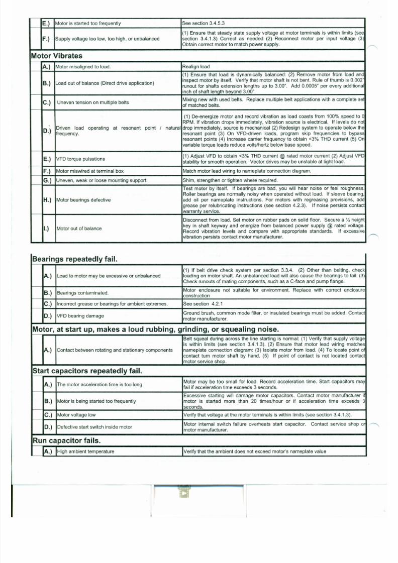
7/30/2019 MANUAL DE USUARIO GRANALLADORA (2).pdf
http://slidepdf.com/reader/full/manual-de-usuario-granalladora-2pdf 237/240
stability for smooth operation. Vector drives may be unstable at light load.
F.) Motor miswired at terminal box Match motor lead wiring to nameplate connection diagram.
G.) Uneven, weak or loose mounting support. Shim, strengthen or tighten where required.
Test motor by itself. If bearings are bad, you will hear noise or feel roughness.
Roller bearings are normally noisy when operated without load. If sleeve bearing,
H.) Motor bearings defective add oil per nameplate instructions. For motors with regreasing provisions, add
grease per relubricating instructions (see section 4.2.3). If noise persists contac
warrantv service.
Disconnect from load. Set motor on rubber pads on solid floor. Secure a Y,height
I.) Motor out of balancekey in shaft keyway and energize from balanced power supply @ rated voltage.
Record vibration levels and compare with appropriate standards. If excessive
vibration persists contact motor manufacturer.
Bearings repeatedly fail.
(1) If belt drive check system per section 3.3.4. (2) Other than belting, check

7/30/2019 MANUAL DE USUARIO GRANALLADORA (2).pdf
http://slidepdf.com/reader/full/manual-de-usuario-granalladora-2pdf 238/240
P.O. Box 8003
VVausau, VVI54401-8003
PH:(715) 675-3311
Model #256TTFNA4001
Winding: K2562124
NP HP: 20
NP VOLTS: 460
NP AMPS: 23.5
NP RPM: 3530
NP EFF: 90.2%
NP PF: 87.5%
GTD EFF: 88.5%
Certification Data Sheet(DA TA IS BASED ON 460 VOL TS)
Outline Drawing: B-SS2030 15-1225
Connection Diagram: A-EE7308
DESIGN: B Frame: 256T
Max Load
FREQ: 60 HZ Inertia: 58 (Ib ft2)
Approx Mtr
LR CODE: G Wgt: 334
95% PF Corr: 5 Rotor Inertia: 1 (Ib ft2)
Sound@ 1M: 78 dBA Starts/Hour: 2 (NEMA VVK2)
Ambient 40 C Stall Time: 20 See
Service Factor: 1.15 Insulation: F
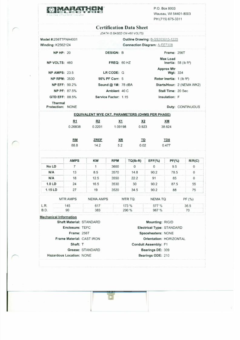
7/30/2019 MANUAL DE USUARIO GRANALLADORA (2).pdf
http://slidepdf.com/reader/full/manual-de-usuario-granalladora-2pdf 239/240
ThermalProtection: NONE Duty: CONTINUOUS
--,-- -
EQUIVALENT WYE CKT. PARAMETERS (OHMS PER PHASE)
R1 R2 X1 X2 XM
0.26838 0.2201 1.09198 0.923 38.624
RM
88.8
ZREF XR TO TOO
14.2 5.2 0.02 0.477
I KW RPM TQ(lb-ft) I EFF(%) I PF(%) RlR(C)-~ - - ----.- - ---- --_. .--!
________ -+~_AM~~
THREE A HA SEHIG H VOLTAGE DUAL VOLTA~E MOTOR
- r
T1 • L1
T2 • L 2
T3 • L 3
T4
T7 >T5
TB>
T6
>9
LOW VOLTAGE
T1L1
E E 7 3 0 8
T1
T4
T9
T7
TB
T6
T5
T2
T3
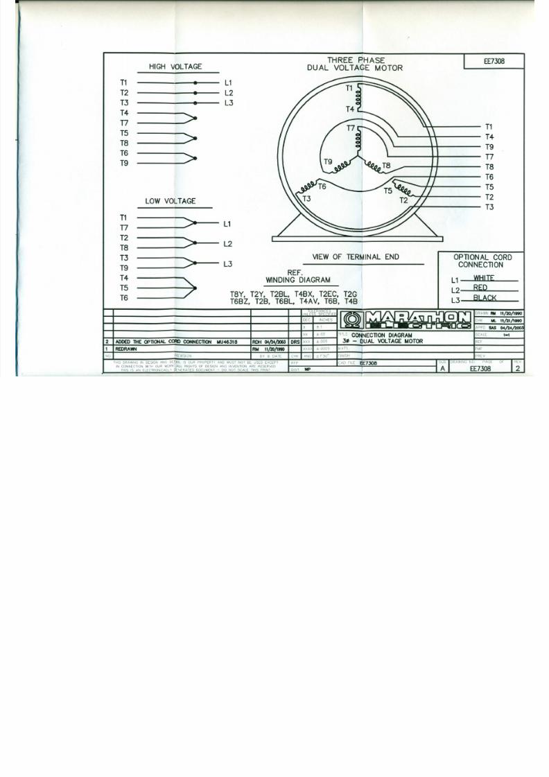
7/30/2019 MANUAL DE USUARIO GRANALLADORA (2).pdf
http://slidepdf.com/reader/full/manual-de-usuario-granalladora-2pdf 240/240
T7
T2TB
T3
T9
T4
T5
T6
---->---
----y----- L 2
VIEW O F TER~INAL END
----~»--3REF.
W IND ING D IAGRAM
TB Y , T2Y , T28L , T48X, T2EC, T2G (T68Z, T28, T68L , T4A V, T68, T4B
<___7
OPT IONA L CORDCONNECTION
L 1 WHITE
L 2 RED
L3~LACK
DRAWN RIll 11/20/18110
••. 11/21/18110
APPD $AS 04 - /24,SCALE 1-1
REF-MF-REY
S~E IDRAWING ~E7;~~EOF
~I
~+~~=__~~~~~ -I- ~4;';;';"~;':';;'_-4TITlE C O N N E C T IO N D IA G R A t- 4
2 ADDED THE OP ll ONA l. CO ftO CONNECllON M U48318 RDH 04/24fJ/m 3 . - I b U A L V O LT A G E t - 4 0 T O R
1 I REDRAYitl IRM 11/20/1990I I . x x x x i ±OOD5 IMAn
No,l REVISION I BY & DATE I CHK I ANG I ±7'30" IFINISH
THIS DRAWING IN DESIGN AND DErAil IS OUR PROPERTY AND MUST NOT BE USED EXCEPT I RFP ICAD FilE f'-- IIN CONNECTION WITH OUR WORK ALL RIGHTS OF DESIGN AND INVENTION ARE RESERVED
THIS IS AN ELECTRONICALLY ~ENERATED DOCUMENT - 00 NOl SCALE THIS PRINT 015T ~
.xI±1