man205-0343001en rev p changes not highlighted · cat. no. man205-0343001en rev. p 8 ... 9.34...
TRANSCRIPT

TECHNICIAN MANUAL
Pre/Post-vacuum Class B Table–top Autoclave
Model ELARA 11
Cat. No. MAN205-0343001EN Rev. P 8-10-11Manufactured by: Tuttnauer Co. Ltd., Har Tuv Industrial zone B P.O.Box 170, Beit Shemesh 99000, Israel Tel: 972 2 9904611, Fax: 972 2 9904730 Tuttnauer U.S.A. Co, Ltd. 25 Power Drive Hauppauge, NY, 11788, USA. Tel (631) 737 4850, (800) 624 5836, Fax: (631) 737 0720
(CAT Controller)

Page 1 of 129 Pages
TABLE OF CONTENTS PARAGRAPH PAGE NO. 1 INTRODUCTION ................................................................................................... 4
2 SYMBOL DESCRIPTION ..................................................................................... 4
3 INSTALLATION .................................................................................................... 7
3.1 Lifting and carrying ...................................................................................... 7
3.2 Unpacking the autoclave ............................................................................... 7
3.3 Installation preparations ............................................................................... 7
3.4 Connections to Utility Supplies ..................................................................... 8
3.5 Final adjustments .......................................................................................... 8
3.6 Operating the autoclave ................................................................................ 9
4 PERIODICAL TESTS .......................................................................................... 10
5 WATER QUALITY ............................................................................................... 11
5.1 Water for Generating Steam ....................................................................... 11
6 CONTROL SYSTEM DESCRIPTION ................................................................ 12
6.1 The main board includes: ........................................................................... 12
6.2 The high voltage board (AC Board) includes: ........................................... 13
7 CHECKING AND CHANGING PARAMETERS AND OTHER DATA ........... 14
7.1 Menu ............................................................................................................ 15
7.2 Parameters ................................................................................................... 16
7.3 Digital Inputs ............................................................................................... 28
7.4 Digital Outputs............................................................................................. 29
7.5 Analog Inputs .............................................................................................. 30
7.6 Calibration ................................................................................................... 31
7.7 Setting the Clock .......................................................................................... 37
7.8 Printer Test .................................................................................................. 38
7.9 Language ..................................................................................................... 39
7.10 History .......................................................................................................... 40
7.11 More options ................................................................................................ 41
8 RESSETTING THE AUTOCLAVE ..................................................................... 43
9 MAINTENANCE AND REPLACEMENT PROCEDURES .............................. 44
9.1 Preliminary Operations for Each Technician Call .................................... 44
9.2 Safety tests after repair ................................................................................ 45
9.3 Dismantling the Outer Covers of the Autoclave ......................................... 46
9.4 Replacing the Safety Valve .......................................................................... 47
9.5 Replacing chamber heater .......................................................................... 48
9.6 Replacing steam generator heater .............................................................. 50
9.7 Replacing the steam generator cut-off thermostat ..................................... 51
9.8 Replacing and cleaning the generator’s water level electrode .................. 52
9.9 Replacing the Drain Valve .......................................................................... 54
9.10 Replacing the Door Cover ........................................................................... 55
9.11 Replacing the Front Panel .......................................................................... 56
Page 2 of 129 Pages
9.12 Replacing the Printer Door ......................................................................... 57
9.13 Replacing the Door Handle......................................................................... 58
9.14 Replacing the Plastic Handle Cover ........................................................... 59
9.15 Replacing the Printer .................................................................................. 60
9.16 Replacing the Door Switch .......................................................................... 61
9.17 Replacing the fuse on the Electronic Board ............................................... 63
9.18 Replacing the fuses of the transformer ....................................................... 64
9.19 Replacing the water pump ........................................................................... 65
9.20 Replacing the vacuum pump ....................................................................... 66
9.21 Replacing the Plunger or Coil of the 1/4" Solenoid Valve ........................ 67
9.22 Replacing the Electronic Boards ................................................................ 68
9.23 Replacing the switch .................................................................................... 73
9.24 Draining the generator ................................................................................ 74
9.25 Emergency Door Opening ........................................................................... 75
9.26 Replacing the water reservoirs .................................................................... 77
9.27 Cleaning the water reservoirs ..................................................................... 79
9.28 Replacing the cut-of thermostat for the Chamber Heater ......................... 80
9.29 Replacing the PT100 temperature sensor for the Chamber Heater .......... 82
9.30 Replacing the internal PT100 ..................................................................... 84
9.31 Replacing the pressure transducer ............................................................. 86
9.32 Cleaning the steam generator ..................................................................... 87
9.33 Replacing the cooler and the cooler's fan .................................................. 88
9.34 Testing procedure for the chamber PT100 ................................................. 90
9.35 Testing procedure for the heating element PT100 ..................................... 92
9.36 Testing procedure for the chamber pressure transducer ........................... 94
9.37 Testing procedure for the Generator pressure transducer” ...................... 95
9.38 Door Locking Solenoid................................................................................ 97
10 IN-OUT TEST ....................................................................................................... 99
11 TROUBLESHOOTING ...................................................................................... 101
11.1 Preliminary Check ..................................................................................... 101
11.2 Troubleshooting procedure ....................................................................... 102
12 PRESSURE VS TEMPERATURE FOR SATURATED STEAM .................... 114

Page 3 of 129 Pages
TABLE OF CONTENTS (Continue)
PARAGRAPH PAGE NO. Front View ...................................................................................................................... 5 Rear View ....................................................................................................................... 6 Control System Block Diagram ................................................................................... 12 Assembled Nova4-D2 Board ........................................................................................ 69Nova4-A2 Board ........................................................................................................... 70 Nova4-D2 Board .......................................................................................................... 71 Exploded Drawing – Rear.......................................................................................... 118 Table for Exploded Drawing – Rear ......................................................................... 119 Exploded Drawing – Door ......................................................................................... 120 Table for Exploded Drawing – Door ......................................................................... 121 Exploded Drawing – PT-100 and Cut-Off ................................................................ 122 Table for Exploded Drawing – PT-100 and Cut-Off ................................................ 123 Exploded Drawing – Generator ................................................................................. 124 Control Unit ............................................................................................................... 125 Partial Front View ..................................................................................................... 126 Electrical Diagram ..................................................................................................... 127 Piping Diagram .......................................................................................................... 128 Piping Layout ............................................................................................................. 129
Page 4 of 129 Pages
1 INTRODUCTION This Technician's Manual, together with the operator’s manual, forms the
complete set of the Operation and Maintenance instructions for the Elara 11 pre and post vacuum autoclave. This manual is intended for the use of the technician. It is strongly recommended that only qualified and Tuttnauer factory trained personnel service this autoclave and do so in accordance with the instructions in this manual. Any unauthorized service may result in the invalidation of the manufacturer’s guarantee.
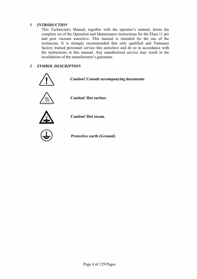
2 SYMBOL DESCRIPTION
Caution! Consult accompanying documents
Caution! Hot surface
Caution! Hot steam.
Protective earth (Ground)
Page 5 of 129 Pages
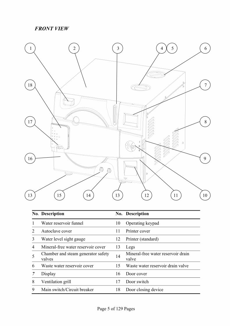
FRONT VIEW
No. Description No. Description
1 Water reservoir funnel 10 Operating keypad
2 Autoclave cover 11 Printer cover
3 Water level sight gauge 12 Printer (standard)
4 Mineral-free water reservoir cover 13 Legs
5 Chamber and steam generator safety valves
14 Mineral-free water reservoir drain valve
6 Waste water reservoir cover 15 Waste water reservoir drain valve
7 Display 16 Door cover
8 Ventilation grill 17 Door switch
9 Main switch/Circuit breaker 18 Door closing device
5 4 6
8
9
101115 13 12
1 2 3
718
17
16
13 14

Page 6 of 129 Pages
REAR VIEW
No. Description
1 Mineral-free water reservoir cover
2 Waste water reservoir cover
3 Ventilation grills
4 Air filter service cover
5 Opening for calibration
6 Main power electric cable socket
5
4
3
1
2
3
6

Page 7 of 129 Pages
3 INSTALLATION CAUTION:
Any operation described in section 3 shall be performed by a qua lified technician only.
3.1 Lifting and carrying CAUTION:
Before moving the a utoclave, Make sure that the electric cord is disconnected from the pow er, and there is no press ure in th e chamber and in the generator. Attention! The pressure of th e generator does not decreas e immediately when the equipment is turned off. Wait approx. ½ an hour to ve rify that the pressu re has decreased to a tmospheric pressure. 1. Disconnect the power supply cord. 2. Drain the water from both reservoirs. To avoid injuries, lifting and carrying should be done with at least two persons or by using a fork-lift or any other mechanical aid.
Do not drop the device! 3.2 Unpacking the autoclave
Unpack the autoclave and inspect for mechanical damage upon receipt. Observe packing method and retain packing materials until the unit has been inspected. Mechanical inspection involves checking for signs of physical damage such as: scratched panel surfaces, broken knobs, etc. To avoid injuries, lifting and carrying of the autoclave should be done with at least two persons or by using a fork-lift or any other mechanical aid.
3.3 Installation preparations
1. Check and verify that the counter carrying the autoclave is a rigid and leveled surface and can carry a load of 225 lbs (102kg).
Attention: The Elara11 is not designed for use on any standard slide out shelf. If
it is necessary to use a slide out shelf, it must be tested and/or rated for 225 lb (102kg) or more.
Check and verify that the counter dimensions are, at least, 22” wide x 24” deep (55cm x 63.5cm).
2. Keep the back and the sides of the autoclave approximately 2” (5 cm) away from the wall to allow ventilation and facilitate the device disconnection.
3. If placed in a cabinet, verify that the rear of the cabinet is open to allow ventilation.
4. Insufficient space for ventilation may result in an increase of the autoclave's temperature that may cause a malfunction or damage the instrument.
5. It is recommended that enough space be left around the autoclave to give a technician access for servicing the machine.
6. Check and verify that the room ventilation is 10 cycles per hour minimum.
Page 8 of 129 Pages
7. Check and verify that the ambient temperature range is 41˚F - 104˚F (5˚C - 40˚C), it is preferable not to exceed 86˚F (30˚C).
8. Check and verify that the ambient relative humidity does not exceed 85%.
3.4 Connections to Utility Supplies 1. Check and verify that the power supply is a 1 phase, 230Vac ±5%,
50/60Hz (as appropriate), 15A supply.
2. Check and verify that the autoclave is connected to separate power source to avoid flickers of light or sensitive devices.
3. Check and verify grounding of the autoclave.
4. Check and verify that the electrical net is protected with a current leakage safety relay.
3.5 Final adjustments At the time of installation, befo re the autoclave can be okayed for
daily operation the service technician needs to perform the follow ing preliminary checks: a. Integrity Check Perform a visual check to verify that there are no dents, scratches or
broken components on the autoclave. b. Support surface check Make a visual check that the surface is level and strong enough to
support the autoclave. c. The leakage current test Test the precise operation of the earth leakage relay. d. Ground Check Test the continuity of the grounding connection. e. Safety Valve Check Test the safety valve as per the instructions in "Checking the Safety
Valve" in the Operator’s Manual. f. Door check Ensure that the door locking mechanism is functioning properly g. Setting clock and date See instruction in the user manual clause. 7.3. h. Atmospheric Pressure check: the unit is set from the factory at 100
kpa, this is atmospheric pressure at sea level. If the unit is located more that 500 ft above or below sea level then the Atmos. Press parameter must be set, see sec 7.2.7
i. Cycle check: run a B&D Test to ensure that all systems in the unit are functioning properly.
j. Reset the autoclave see sec 8. After the above steps are performed, the autoclave is ready for daily
operation.
Page 9 of 129 Pages
3.6 Operating the autoclave 1 Plug the power cord into the power socket.
2 Turn on the Main Switch / Circuit Breaker (see front view).
3 Select "Vacuum Test" cycle to keep the steam generator and heating elements from heating up. See Selecting a Program in the Operator’s Manual.
4 Open the door of the autoclave and remove the trays and the packaging material.
5 Fill the Mineral Free Water Reservoir with water meeting the quality specs in section 5.1 as follows:
5.1. Fill with 4 liters of mineral free water by pouring it into the front reservoir fill opening at the top of the machine (see front view).
5.2. Fill the remaining quantity by pouring water gently, into the front funnel until it reaches the required level on the water level sight gauge (See Front View).
6 Insert a paper roll in the printer (see printer handling in the Operator’s Manual).
7 Close the door and perform a Vacuum Test. If the test fails perform another test since the fail may be a result of moisture in the air. If the second test fails it may be necessary to run Program 2 with the long drying cycle to remove any excess moisture that is causing the test to fail.
8 If the Vacuum Test is successful then select the B&D Test cycle.
At this stage the chamber and steam generator will be heating up. It will take approximately 15 minutes (from selecting the B&D Test).
9 While waiting for the unit to heat up explain and instruct the operator as follows (use the operation manual as reference):
9.1. Operation principals of the autoclave.
9.2. Preparation for sterilizing instruction including loading instructions.
9.3. Intended use of each cycle.
9.4. Selecting a cycle.
9.5. Water filling method.
9.6. Displayed error and operational messages.
9.7. Monitoring and changing parameters.
9.8. Printer handling.
9.9. Maintenance instructions
10 Perform a B&D test with a chemical indicator.
11 The operator shall perform a cycle under supervision of the technician.

Page 10 of 129 Pages
4 PERIODICAL TESTS PERIOD TEST 1 month Test the safety valve by operating it.
6 months Remove the autoclave’s cover, tighten the heaters’ screws and electrical connections, valves and connectors in the control box.
Year
Check the continuity of the grounding connections. Check the temperature and pressure calibration. Perform validation of the autoclave. Check the precise operation of the earth leakage relay. Check that the autoclave is leveled. Check the safety elements; safety valve, safety and cut-off thermostats door locking mechanisms. Run basic programs of the autoclave and check the operation sequences, the sterilization parameters etc. Check the water reservoir, piping, plastic parts and electric wires. Check and tighten the piping joints to avoid leakage. Check and tighten all screw connections in the control box, heaters and valves and instrumentation. Calibrate the temperature and pressure once a year or in reference to local rules or regulations (refer to the section on Calibration).
5 years Observe the closing device for excessive wear Safety tests (pressure vessel, efficiency, electrical) shall be performed in accordance with local rules or regulations, by an authorized inspector.
Only an authorized technician shall perform the 6-months and yearly tests!
Page 11 of 129 Pages
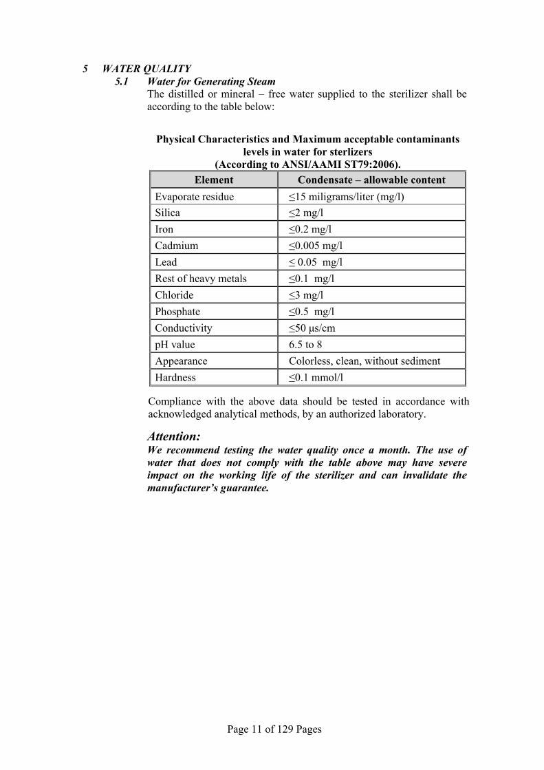
5 WATER QUALITY 5.1 Water for Generating Steam The distilled or mineral – free water supplied to the sterilizer shall be
according to the table below:
Physical Characteristics and Maximum acceptable contaminants levels in water for sterlizers
(According to ANSI/AAMI ST79:2006). Element Condensate – allowable content
Evaporate residue ≤15 miligrams/liter (mg/l)
Silica ≤2 mg/l
Iron ≤0.2 mg/l
Cadmium ≤0.005 mg/l
Lead ≤ 0.05 mg/l
Rest of heavy metals ≤0.1 mg/l
Chloride ≤3 mg/l
Phosphate ≤0.5 mg/l
Conductivity ≤50 μs/cm
pH value 6.5 to 8
Appearance Colorless, clean, without sediment
Hardness ≤0.1 mmol/l
Compliance with the above data should be tested in accordance with acknowledged analytical methods, by an authorized laboratory.
Attention: We recommend testing the water quality once a month. The use of
water that does not comply with the table above may have severe impact on the working life of the sterilizer and can invalidate the manufacturer’s guarantee.

Page 12 of 129 Pages
6 CONTROL SYSTEM DESCRIPTION
The control system is based on 2 electronic boards, see the diagram below.
Control system block diagram
The control system contains the parts listed below: Main board AC high voltage power board Transformer (230VAC primary / 6, 12, 18, 24VAC secondary) Electrical wires
6.1 The main board includes:
Stabilized power supply 24VAC & 5VAC Analog inputs for reading the analog sensors (temperature sensors,
pressure sensor, water level electrodes) Digital inputs for reading the digital indicators (door switch, float
reservoir if available) Digital outputs to control the solenoid valves and the door lock. Digital outputs to send signal to high voltage board or power
element drivers to control power elements. Display A memory logging the previous cycles Drivers for printer Real time clock to serve as clock to the system Connection to the printer. It is connected directly to this board
through a flat cable 24 pins.
Digital input
Press. Sensors electrodes
Jack. temp
Chamb. Temp
Door Lock
Solenoid valves
Water Pump
Power Circuit Breaker
Heaters
Vacuum Pump
L N GND Power Inlet
DISPLAY
Keypad
DPU30 Printer
PC
Power Transformer
AC Board
Main Board

Page 13 of 129 Pages
6.2 The high voltage board (AC Board) includes: High power outputs to control the heaters and the pumps. Circuit breaker The board provides four outputs for four high AC devices as
follows: 1. Steam generator heater (2200 Watt).
2. Chamber wall heater (500 Watt).
3. Vacuum pump.
4. Water pump.
Connection between the 2 cards
Page 14 of 129 Pages
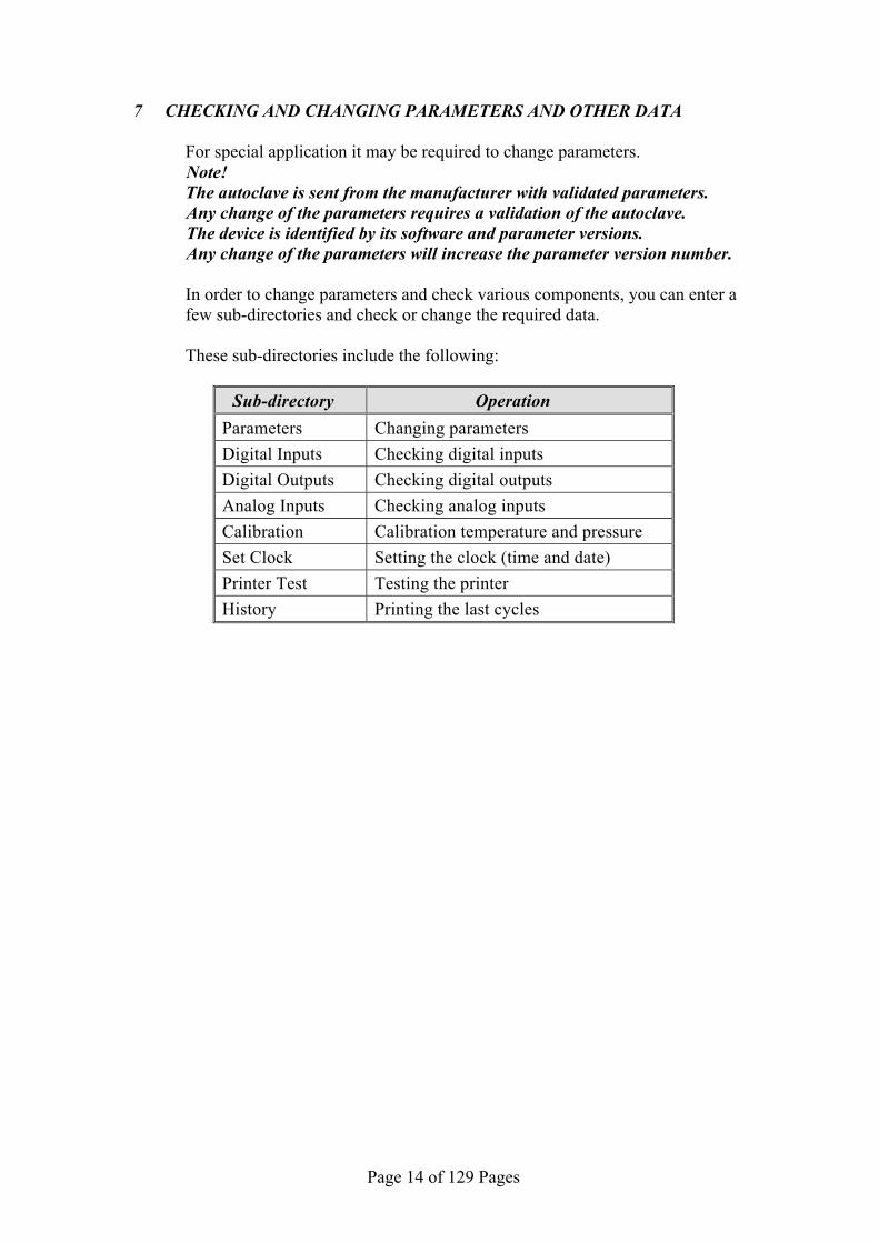
7 CHECKING AND CHANGING PARAMETERS AND OTHER DATA For special application it may be required to change parameters. Note! The autoclave is sent from the manufacturer with validated parameters. Any change of the parameters requires a validation of the autoclave. The device is identified by its software and parameter versions. Any change of the parameters will increase the parameter version number. In order to change parameters and check various components, you can enter a
few sub-directories and check or change the required data. These sub-directories include the following:
Sub-directory Operation Parameters Changing parameters
Digital Inputs Checking digital inputs
Digital Outputs Checking digital outputs
Analog Inputs Checking analog inputs
Calibration Calibration temperature and pressure
Set Clock Setting the clock (time and date)
Printer Test Testing the printer
History Printing the last cycles

Page 15 of 129 Pages
7.1 Menu
Follow the instructions below for entering the sub-directories and performing the menu operation.
1. Main screen
134°C004’ 001’
30.0°C 100kPaG
08:03:06
Turn on the autoclave with the main power switch located on the right side of the autoclave (see FRONT VIEW). The main screen is displayed. To enter the menu press simultaneously the UP and DOWN pushbuttons.
2. Enter Code
ENTER CODE
0333 SET EXIT
ENTER CODE will be displayed. Enter the technician code (0333) as follows: The cursor is under the right digit. To change the right digit, press the UP or DOWN pushbuttons. Each press on the UP pushbutton will increase the digit by 1 and each press on the DOWN pushbutton will decrease it by 1. Change this digit as required and press the START/STOP pushbutton to move the cursor to the second digit from the right. Repeat this until the curser is under SET (SET is blinking), and then press the UP pushbutton to enter the MENU.
3. Menu
The MENU contains 1 1 sub-directories (see display on the left). The 7 top sub-director ies are displayed when entering "Menu" and the remaining 4 directories are displayed when rolling dow n. Move to the required sub-directory using the UP and DOWN pushbutton. The pointed sub-directory is blinking. Pressing START/STOP pushbutton will select the blinking directory and the required directory will be displayed. To return to the previous display press the UP and DOWN pushbuttons until reaching EXIT. When EXIT is blinking, press the START/STOP pushbutton and the previous screen will be displayed.

Page 16 of 129 Pages
7.2 Parameters
This section describes the parameters, how they affect the process and the way to change them.
Listed bellow are all the available parameters. Each section describes the parameter, the minimum and maximum
allowed values and the changing resolution. Also included are the pre-set values of the parameters for each cycle (default value).
NOTE: If a parameter is modified, the only way to return to the original
value is to manually reenter it. A global parameter is a parameter that by changing its value in
one program, it is changed in all the other programs to receive the same value.
To change a non-global value, i.e. specific parameter for each program, choose first the required sterilization program in the main screen of the autoclave and then enter the MENU and the sub-directory PARAMETERS.
7.2.1 Ster Temp - sterilization temperature - This parameter will set the desired temperature for sterilization
Resolution: 0.1°C Minimum value: Default value Maximum value: 136°C
Cycle
Flash 134
Wdry 134
No Dry 121
Wdry 121
Delicate 121
B&D Test
Vacuum Test
Default Value 134 134 121 121 121
Fixed value
Fixed value
7.2.2 Ster Time – sterilization time This parameter will set the time desired for sterilization.
Resolution: 0.1 min Minimum value: Default value Maximum value: 99.9 min
Cycle
Flash 134
Wdry 134
No Dry 121
Wdry 121
Delicate 121
B&D Test
Vacuum Test
Default Value 4 4 20 20 20
Fixed value
Fixed value

Page 17 of 129 Pages
7.2.3 Dry Time – drying time
This parameter will set the time desired for drying.
Resolution: 0.1 min Minimum value: Default value Maximum value: 99.9 min
Cycle
Flash 134
Wdry 134
No Dry 121
Wdry 121
Delicate 121
B&D Test
Vacuum Test
Default Value 1 20 0 20 0
Fixed value
Fixed value
7.2.4 Vac Pulses – number of pulses
This parameter sets the number of vacuum pulses during the air
removal stage..
Resolution: 1 Minimum value: 0 Maximum value: 5
Cycle
Flash 134
Wdry 134
No Dry 121
Wdry 121
Delicate 121
B&D Test
Vacuum Test
Default Value 2 3 2 3 2
Fixed value
Fixed value
7.2.5 SterPressAdd - addition to the sterilization pressure
This defines the required addition to the sterilization pressure in
kPa in order to increase the sterilization temperature. For example, for a sterilization temperature of 121°C the
required pressure is 205 kPa. Since the system controls the sterilization process according to pressure, if SterPressAdd equals “0”, the system will maintain the pressure at 205 kPa . If the value is at 5 kPa, the system will be maintained at 210 kPa and the temperature will be 121.8°C, and so on.
Resolution: 0.1 kPa Minimum value: 0 kPa Maximum value: 40 kPa
Cycle
Flash 134
Wdry 134
No Dry 121
Wdry 121
Delicate 121
B&D Test
Vacuum Test
Default Value 9 9 9 9 9
Fixed value
Fixed value

Page 18 of 129 Pages
7.2.6 End Temp - temperature at the end of the cycle
This parameter will set the temperature that the chamber must reach before the cycle can end.
Resolution: 0.1°C Minimum value: 50°C Maximum value:136°C
Cycle
Flash 134
Wdry 134
No Dry 121
Wdry 121
Delicate 121
B&D Test
Vacuum Test
Default Value 120 120 110 110 110
Fixed value
Fixed value
7.2.7 ATMPressure – ambient pressure
This parameter tells the unit the atmospheric pressure of the location in which the autoclave is installed. The pressure entered must be with an accuracy of 5% of the actual atmospheric pressure for that location. It is a global parameter that means that you only need to enter this parameter once in anyone cycle and all cycles will be updated.
This value can easily be calculated by knowing the altitude of your location. The atmospheric pressure at Sea Level is 100 kPa For every 100 meter above sea level, the atmospheric pressure
drops 1 kPa. For every 100 meter below sea level, the atmospheric
pressure increases 1 kPa. Changes in pressure do to weather will not affect the accuracy of
this unit.
Resolution: 0.1 kPa Minimum value: 70 kPa Maximum value: 110 kPa
Cycle
Flash 134
Wdry 134
No Dry 121
Wdry 121
Delicate 121
B&D Test
Vacuum Test
Default Value 100 kPa (global parameter)
7.2.8 Pulse vac 1 – Vacuum value in the first pulse This parameter defines the vacuum value in pulse no.1 of the
prevacuum stage.
Resolution: 0.1°kPa Minimum value: 5kPa Maximum value:100kPa
Cycle
Flash 134
Wdry 134
No Dry 121
Wdry 121
Delicate 121
B&D Test
Vacuum Test
Default Value 25.0 15.0 25.0 15.0 25.0
Fixed value
Fixed value

Page 19 of 129 Pages
7.2.9 Pulse vac T1 – vacuum time after Pulse vac 1 This parameter defines the period that vacuum is built after
reaching the value defined in Pulse vac 1.
Resolution: 1sec Minimum value: 5sec Maximum value:360sec
Cycle
Flash 134
10
Wdry 134
No Dry 121
Wdry 121
Delicate 121
B&D Test
Vacuum Test
Default Value 10 30 10 30 10
Fixed value
Fixed value
7.2.10 Pulse press 1 - Pressure value in the first pulse This parameter defines the pressure value (above zero) in pulse
no.1 of the prevacuum stage.
Resolution: 0.1kPa Minimum value: 70kPa Maximum value:200kPa
Cycle
Flash 134
Wdry 134
No Dry 121
Wdry 121
Delicate 121
B&D Test
Vacuum Test
Default Value 140.0 140.0 140.0 140.0 140.0
Fixed value
Fixed value
7.2.11 Pulse vac 2 – Vacuum value in middle pulses This parameter defines the vacuum value in all pulses except
first and last pulse of the prevacuum stage.
Resolution: 0.1kPa Minimum value: 5kPa Maximum value:100kPa
Cycle
Flash 134
Wdry 134
No Dry 121
Wdry 121
Delicate 121
B&D Test
Vacuum Test
Default Value 25.0 20.0 25.0 20.0 25.0
Fixed value
Fixed value
7.2.12 Pulse vac T2 - vacuum time after Pulse vac 2 This parameter defines the period that vacuum is built after
reaching the value defined in all pulses defined by Pulse vac 2.
Resolution: 1sec Minimum value: 1sec Maximum value:300sec
Cycle
Flash 134
Wdry 134
No Dry 121
Wdry 121
Delicate 121
B&D Test
Vacuum Test
Default Value 10 30 10 30 10
Fixed value
Fixed value
Page 20 of 129 Pages
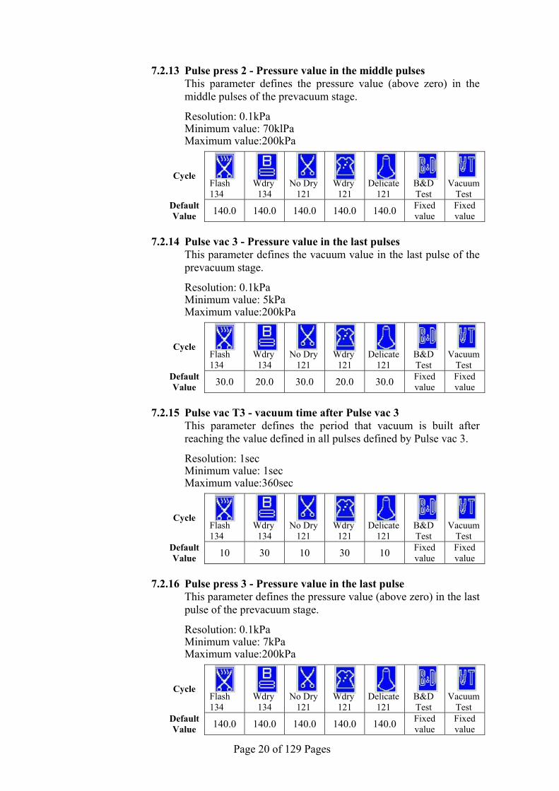
7.2.13 Pulse press 2 - Pressure value in the middle pulses This parameter defines the pressure value (above zero) in the
middle pulses of the prevacuum stage.
Resolution: 0.1kPa Minimum value: 70klPa Maximum value:200kPa
Cycle
Flash 134
Wdry 134
No Dry 121
Wdry 121
Delicate 121
B&D Test
Vacuum Test
Default Value 140.0 140.0 140.0 140.0 140.0
Fixed value
Fixed value
7.2.14 Pulse vac 3 - Pressure value in the last pulses This parameter defines the vacuum value in the last pulse of the
prevacuum stage.
Resolution: 0.1kPa Minimum value: 5kPa Maximum value:200kPa
Cycle
Flash 134
Wdry 134
No Dry 121
Wdry 121
Delicate 121
B&D Test
Vacuum Test
Default Value 30.0 20.0 30.0 20.0 30.0
Fixed value
Fixed value
7.2.15 Pulse vac T3 - vacuum time after Pulse vac 3 This parameter defines the period that vacuum is built after
reaching the value defined in all pulses defined by Pulse vac 3.
Resolution: 1sec Minimum value: 1sec Maximum value:360sec
Cycle
Flash 134
Wdry 134
No Dry 121
Wdry 121
Delicate 121
B&D Test
Vacuum Test
Default Value 10 30 10 30 10
Fixed value
Fixed value
7.2.16 Pulse press 3 - Pressure value in the last pulse This parameter defines the pressure value (above zero) in the last
pulse of the prevacuum stage.
Resolution: 0.1kPa Minimum value: 7kPa Maximum value:200kPa
Cycle
Flash 134
Wdry 134
No Dry 121
Wdry 121
Delicate 121
B&D Test
Vacuum Test
Default Value 140.0 140.0 140.0 140.0 140.0
Fixed value
Fixed value

Page 21 of 129 Pages
7.2.17 Heat Exh on – Opening time of exhaust valve This parameter defines the period that the exhaust valve is open,
during the heating stage, in order to remove the condensate.
Resolution: 0.1sec Minimum value: 1sec Maximum value: 50sec
Cycle
Flash 134
Wdry 134
No Dry 121
Wdry 121
Delicate 121
B&D Test
Vacuum Test
Default Value 10 10 10 10 10
Fixed value
Fixed value
7.2.18 Heat Exh off - Closing time of exhaust valve This parameter defines the period that the exhaust valve is
closed, during the heating stage.
Resolution: 0.1sec Minimum value: 0sec Maximum value: 1000sec
Cycle
Flash 134
Wdry 134
No Dry 121
Wdry 121
Delicate 121
B&D Test
Vacuum Test
Default Value 200 200 200 200 200 Fixed
value Fixed value
7.2.19 Ster Exh on - Opening time of exhaust valve This parameter defines the period that the exhaust valve is open,
during the sterilization stage.
Resolution: 0.1sec Minimum value: 0sec Maximum value: 50sec
Cycle
Flash 134
Wdry 134
No Dry 121
Wdry 121
Delicate 121
B&D Test
Vacuum Test
Default Value 5 5 5 5 5
Fixed value
Fixed value
7.2.20 Ster Exh off - Closing time of exhaust valve This parameter defines the period that the exhaust valve is
closed, during the sterilization stage.
Resolution: 0.1sec Minimum value: 0sec Maximum value: 1000sec
Cycle
Flash 134
Wdry 134
No Dry 121
Wdry 121
Delicate 121
B&D Test
Vacuum Test
Default Value 200 200 200 200 200
Fixed value
Fixed value

Page 22 of 129 Pages
7.2.21 Exh Shoot on - Opening time of exhaust valve This parameter defines the period that the exhaust valve is open,
during the exhaust stage.
Resolution: 0.1sec Minimum value: 0sec Maximum value: 1000sec
Cycle
Flash 134
Wdry 134
No Dry 121
Wdry 121
Delicate 121
B&D Test
Vacuum Test
Default Value 1 1 1 1 10
Fixed value
Fixed value
7.2.22 Exh Shoot off - Closing time of exhaust valve This parameter defines the period that the exhaust valve is
closed, during the exhaust stage.
Resolution: 0.1sec Minimum value: 0sec Maximum value: 1000sec
Cycle
Flash 134
Wdry 134
No Dry 121
Wdry 121
Delicate 121
B&D Test
Vacuum Test
Default Value 0 0 0 0 100
Fixed value
Fixed value
7.2.23 Dry Air on - Opening time of air valve This parameter defines the period that the air valve is open,
during the drying stage.
Resolution: 0.1sec Minimum value: 0sec Maximum value: 1000sec
Cycle
Flash 134
Wdry 134
No Dry 121
Wdry 121
Delicate 121
B&D Test
Vacuum Test
Default Value 20 20 20 20 20
Fixed value
Fixed value
7.2.24 Dry Air off - Closing time of air valve This parameter defines the period that the air valve is closed,
during the drying stage.
Resolution: 0.1sec Minimum value: 0sec Maximum value: 1000sec
Cycle
Flash 134
Wdry 134
No Dry 121
Wdry 121
Delicate 121
B&D Test
Vacuum Test
Default Value 200 200 200 200 200
Fixed value
Fixed value

Page 23 of 129 Pages
7.2.25 SterGenPrsAd – Maximum pressure in the generator The value of this parameter plus the sterilization pressure define the maximum pressure in the generator in each program.
Resolution: 0.1kPa Minimum value: 0kPa Maximum value:50kPa
Cycle
Flash 134
Wdry 134
No Dry 121
Wdry 121
Delicate 121
B&D Test
Vacuum Test
Default Value 20.0 20.0 20.0 20.0 20.0
Fixed value
Fixed value
7.2.26 Ster PrintT – printing rate during the sterilization stage
This parameter will set the interval between printings during the sterilization stage.
Resolution: 1 sec Minimum value: 10 sec Maximum value: 360 sec
Cycle
Flash 134
Wdry 134
No Dry 121
Wdry 121
Delicate 121
B&D Test
Vacuum Test
Default Value 60 sec (global parameter)
7.2.27 Print Rate - printing rate except during the sterilization stage
This parameter will set the interval between printings during the other stages.
Resolution: 1 sec Minimum value: 10 sec Maximum value: 360 sec
Cycle
Flash 134
Wdry 134
No Dry 121
Wdry 121
Delicate 121
B&D Test
Vacuum Test
Default Value 180 sec (global parameter)
7.2.28 HeatSter Time – Pre-sterilization heating time
This parameter defines the heating time before sterilization. Increasing the value of this parameter will decrease the heating gradient define.
Resolution: 1 sec Minimum value: 0 sec Maximum value: 1000 sec
Cycle
Flash 134
Wdry 134
No Dry 121
Wdry 121
Delicate 121
B&D Test
Vacuum Test
Default Value 1 1 1 1 1
Fixed value
Fixed value

Page 24 of 129 Pages
7.2.29 WaterGen Time – Addition time for adding w ater into the
generator This parameter defines the addition time that water enters the
generator after the generator's water level electrode senses water..
Resolution: 1 sec Minimum value: 0 sec Maximum value: 30 sec
Cycle
Flash 134
Wdry 134
No Dry 121
Wdry 121
Delicate 121
B&D Test
Vacuum Test
Default Value 10 10 10 10 10
Fixed value
Fixed value
7.2.30 SterPrsLimAd - maximum pressure in the chamber This parameter plus the sterilization pressure define the
maximum pressure in the chamber.
Resolution: 0.1kPa Minimum value: 0kPa Maximum value: 40kPa
Cycle
Flash 134
Wdry 134
No Dry 121
Wdry 121
Delicate 121
B&D Test
Vacuum Test
Default Value 14.0 14.0 14.0 14.0 14.0
Fixed value
Fixed value
7.2.31 Heat Time Err - maximum time of the heating stage This parameter defines the maximum time of the heating stage
until the beginning of the sterilization stage. If the heating continues beyond this limit "ERROR 15" message will be displayed and the cycle will fail.
Resolution: 1 sec Minimum value: 1000 sec Maximum value: 3600 sec
Cycle
Flash 134
Wdry 134
No Dry 121
Wdry 121
Delicate 121
B&D Test
Vacuum Test
Default Value 1500 1500 1500 1500 1500
Fixed value
Fixed value

Page 25 of 129 Pages
7.2.32 Vac Time Err - maximum time of the vacuum stage This parameter defines the maximum time of the vacuum stage.
If the vacuum stage continues beyond this limit "ERROR 14" message will be displayed and the cycle will fail.
Resolution: 1 sec Minimum value: 600 sec Maximum value: 3600 sec
Cycle
Flash 134
Wdry 134
No Dry 121
Wdry 121
Delicate 121
B&D Test
Vacuum Test
Default Value 1000 1000 1000 1000 1000
Fixed value
Fixed value
7.2.33 WaterTimeErr - maximum generator water filling time. This parameter defines the maximum time for filling water in the
generator. If, before a cycle, the water pump has operated as long as defined by this parameter and the water level electrode did not sense water, "ERROR 20" will be displayed and a cycle cannot be started. If this will be during a cycle – the cycle will fail with "low temp" or "low pres".
Resolution: 1 sec Minimum value: 10 sec Maximum value: 200 sec
Cycle
Flash 134
Wdry 134
No Dry 121
Wdry 121
Delicate 121
B&D Test
Vacuum Test
Default Value 90 90 90 90 90
Fixed value
Fixed value
7.2.34 Sleep Power - time until the autoclave turns into "sleep
mode" This parameter defines the time until the autoclave turns into
"sleep mode". This time is counted from the last operation of the autoclave or the last time a pushbutton has been pressed.
Resolution: 0.1hour Minimum value: 0.1hour Maximum value: 999.9hour
Cycle
Flash 134
Wdry 134
No Dry 121
Wdry 121
Delicate 121
B&D Test
Vacuum Test
Default Value 4.0 4.0 4.0 4.0 4.0
Fixed value
Fixed value
Page 26 of 129 Pages
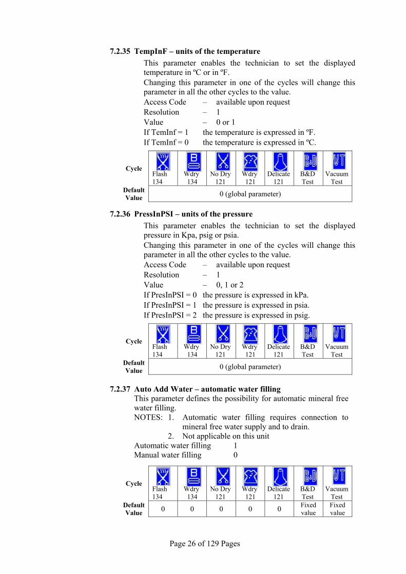
7.2.35 TempInF – units of the temperature
This parameter enables the technician to set the displayed temperature in ºC or in ºF.
Changing this parameter in one of the cycles will change this parameter in all the other cycles to the value.
Access Code – available upon request Resolution – 1 Value – 0 or 1 If TemInf = 1 the temperature is expressed in ºF. If TemInf = 0 the temperature is expressed in ºC.
Cycle
Flash 134
Wdry 134
No Dry 121
Wdry 121
Delicate 121
B&D Test
Vacuum Test
Default Value 0 (global parameter)
7.2.36 PressInPSI – units of the pressure
This parameter enables the technician to set the displayed pressure in Kpa, psig or psia.
Changing this parameter in one of the cycles will change this parameter in all the other cycles to the value.
Access Code – available upon request Resolution – 1 Value – 0, 1 or 2 If PresInPSI = 0 the pressure is expressed in kPa. If PresInPSI = 1 the pressure is expressed in psia. If PresInPSI = 2 the pressure is expressed in psig.
Cycle
Flash 134
Wdry 134
No Dry 121
Wdry 121
Delicate 121
B&D Test
Vacuum Test
Default Value 0 (global parameter)
7.2.37 Auto Add Water – automatic water filling This parameter defines the possibility for automatic mineral free
water filling. NOTES: 1. Automatic water filling requires connection to
mineral free water supply and to drain. 2. Not applicable on this unit
Automatic water filling 1 Manual water filling 0
Cycle
Flash 134
Wdry 134
No Dry 121
Wdry 121
Delicate 121
B&D Test
Vacuum Test
Default Value 0 0 0 0 0
Fixed value
Fixed value

Page 27 of 129 Pages
7.2.38 ElectFillWtr – water conductivity This parameter defines the conductivity level of the mineral free
water in which the water level electrode senses water. .
Resolution: 1 Minimum value: 0 – infinite conductivity Maximum value:9999 – infinite resistance (zero conductivity)
Cycle
Flash 134
Wdry 134
No Dry 121
Wdry 121
Delicate 121
B&D Test
Vacuum Test
Default Value 6000 6000 6000 6000 6000
Fixed value
Fixed value
7.2.39 JackTempStBy - temperature during the Stand-By mode This parameter defines the temperature of the chamber's heating
element during the Stand-By mode.
Resolution: 0.1°F Minimum value: 68°F Maximum value:284°F
Cycle
Flash 134
Wdry 134
No Dry 121
Wdry 121
Delicate 121
B&D Test
Vacuum Test
Default Value 140.0 140.0 140.0 140.0 140.0
Fixed value
Fixed value
7.2.40 JackTempProc – temperature of the chamber's heating element This parameter defines the temperature of the chamber's heating
element during the sterilization stage.
Resolution: 0.1°F Minimum value: 32.1°F Maximum value:284°F
Cycle
Flash 134
Wdry 134
No Dry 121
Wdry 121
Delicate 121
B&D Test
Vacuum Test
Default Value 248.8 248.0 239.0 239.0 239.0
Fixed value
Fixed value
7.2.41 FixGenPress N/A

Page 28 of 129 Pages
7.3 Digital Inputs
This directory enables monitoring the status of the digital inputs. It is possible to view the digital inputs during cycle.
1. To move from one item to another item use the UP and DOWN pushbuttons.
2. To exit to the menu go to EXIT and when it is blinking press the START/STOP pushbuttons.
Displayed
item Displayed
symbol Operation Status
Thermostat (not applicableon this model)
Thermostat disconnects the heaters.
The temperature is above the acceptable temperature.
The temperature is below the acceptable temperature.
Float RESERV (not applicable on this model)
Senses water in the clean water reservoir.
The float doesn’t sense water in the clean water reservoir.
The float senses water in the clean water reservoir.
Door Switch
Senses if the door is open or closed.
The sensor senses the door is closed.
The sensor senses the door is open.
Float Res (not applicable on this model)
Senses water in the waste water reservoir.
The float doesn’t sense water in the waste water reservoir.
The float senses water in the waste water reservoir.

Page 29 of 129 Pages
7.4 Digital Outputs
This directory enables monitoring the status of the digital Outputs. It is possible to view the Digital Outputs during cycle.
1. To move from one item to another item use the UP and DOWN pushbuttons.
2. To exit to the menu go to EXIT and when it is blinking press the START/STOP pushbuttons.
Displayed item
Displayed symbol Operation Remarks
Air Not operating Air valve
(valve 43) Operating
Vac valve Not operating Vacuum valve
(valve 52) Operating Chamb Steam
Not operating Steam inlet valve to the chamber (valve 93) Operating
Fast exh Not operating Fast exhaust valve to the
reservoir (valve 73)
Operating
Dig Out #5 Not operating
Optional Operating
Wtr to Res Not operating
N/A Operating Air VacPump
Not operating Air inlet valve to the vacuum pump (valve 44) Operating
Water Valve Not operating Mineral free water to generator
(valve 21)
Dig Out #9 Not operating
Optional Operating
Door lock Locked position
Door locking pin Unlocked position
Heater 1 Not operating
Steam generator heating element Operating
Heater 2 Not operating
Chamber heating element Operating Vacuum pump
Not operating Vacuum pump Operating
Water pump Not operating
Water pump Operating
Buzzer Off
Buzzer Buzzing
Backlight On
Screen Off

Page 30 of 129 Pages
7.5 Analog Inputs
This directory enables checking the analog Inputs. It is possible to enter this directory while the autoclave is performing a cycle in order to check the devices sending these inputs. 1. To move from one item to another item use the UP and DOWN
pushbuttons. 2. To exit to the menu go to EXIT and when it is blinking press the
START/STOP key.
Displayed item Description
ChambPress Pressure inside the chamber
Chamb Temp Temperature in the chamber
Coil Temp Temperature in jacket of the chamber
Gen Press Pressure in the steam generator
Electr Gen Level of water in the steam generator
ElectrLow This analog input measures the level of water inthe clean water reservoir.
ElectrLow2 This analog input measures the level of water inthe waste water reservoir.
Page 31 of 129 Pages
7.6 Calibration
7.6.1 Calibration components
This directory describes the calibration of the following 4 sensors:
Sensor name Sensor function 1. ChambPress Reads the pressure in the chamber. 2. ChambTemp Reads the temperature in the chamber. 3. CoilTemp Reads the temperature in the jacket. 4. GenPress Reads the pressure in the steam generator.
7.6.2 Required equipment for calibration
Reference temperature tool: (a bead probe thermocouple) Single element sealing gland (to insert the thermocouple
through the validation port). ¼” BSP adaptor (for the validation port) Reference pressure tool: vacuum / pressure gauge in kPa.
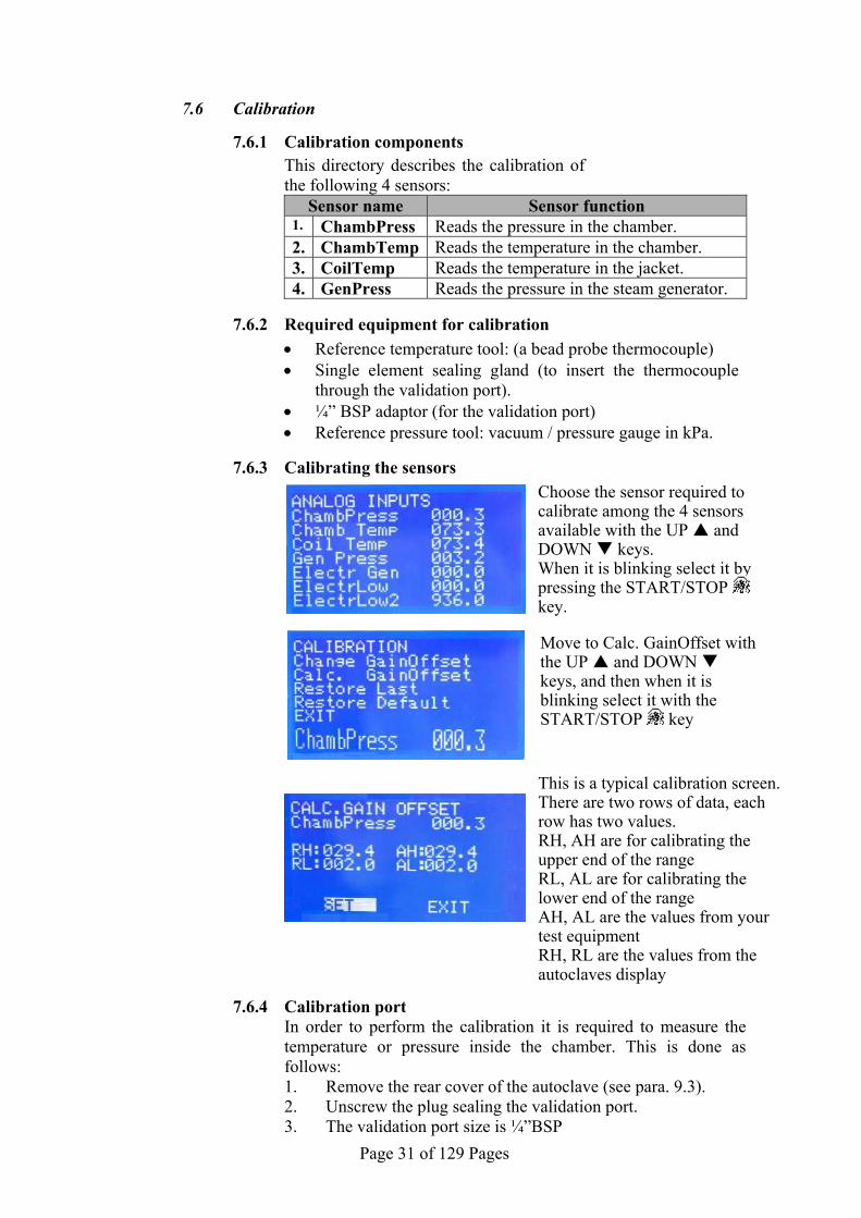
7.6.3 Calibrating the sensors
7.6.4 Calibration port In order to perform the calibration it is required to measure the
temperature or pressure inside the chamber. This is done as follows: 1. Remove the rear cover of the autoclave (see para. 9.3). 2. Unscrew the plug sealing the validation port. 3. The validation port size is ¼”BSP
This is a typical calibration screen.There are two rows of data, each row has two values. RH, AH are for calibrating the upper end of the range RL, AL are for calibrating the lower end of the range AH, AL are the values from your test equipment RH, RL are the values from the autoclaves display
Choose the sensor required to calibrate among the 4 sensors available with the UP and DOWN keys. When it is blinking select it by pressing the START/STOP key.
Move to Calc. GainOffset with the UP and DOWN keys, and then when it is blinking select it with the START/STOP key

Page 32 of 129 Pages
4. Assemble to this port the required measuring tool (temperature sensor or vacuum/pressure gauge) as specified in the calibration instruction.
7.6.5 Calibration operation
Calibration can be preformed in psi and °F, HOWEVER, it is recommended that the calibrations be performed in kPa and °C (see changing parameters sec 7.2.35 & 7.2.36). Make sure the insulation is securely wrapped around the chamber. The side and top panels should also be attached. When calibrating the autoclave you will:
First, acquire the appropriate data, as instructed below. Second, access the calibration page of the software (see sec 7.1 & 7.6.3) Third, use the START/STOP key to move from digit to digit and the UP / DOWN keys to increase and decrease the values according to your data.
7.6.5.1 Calibrating the pressure in the chamber
“ChambPress”
Calibrate the low pressure of the chamber Attach your reference pressure gauge to the validation
port on the back of the chamber and operate a vacuum test. When the unit has reached its lowest vacuum level record the reading of your gauge and the pressure reading for the chamber on the screen of the autoclave.
It is not necessary to abort the cycle, the calibration can be done while the unit is running the cycle. access the calibration page for ChambPress then enter the data as follows (if necessary refer back to 7.6.3):
AL (actual pressure low value): change the AL to the
value shown by your reference pressure gauge. RL (displayed pressure low value): change the RL to the value read from the autoclave display.
Validation port plug

Page 33 of 129 Pages
To save the data move to SET by pressing the
START/STOP key and when it is blinking press the UP key.
If you did not abort the cycle then the chamber pressure on the screen should match your reference gauge.
Calibrate the high pressure of the chamber Attach your reference pressure gauge to the validation
port on the back of the chamber and operate a program of 134°C. When the unit has reached sterilization record the reading of your gauge and the pressure reading for the chamber on the screen of the autoclave.
It is not necessary to abort the cycle, the calibration can be done while the unit is running the cycle. access the calibration page for ChambPress then enter the data as follows (if necessary refer back to 7.6.3): AH (actual pressure high value): change the AH to
the value shown by your reference pressure gauge. RH (displayed pressure high value): change the RH to the value read from the autoclave display.
To save the data move to SET by pressing the START/STOP key and when it is blinking press the UP key.
If you did not abort the cycle then the chamber pressure on the screen should match your reference gauge.
7.6.5.2 Calibrating the temperature in the ch amber “ChambTemp”
Calibrate the low temperature of the chamber When the autoclave is cold, using the sealing gland
insert your reference thermocouple through the validation port and into the chamber. Position it near the Pt100 inside the chamber. Close the chamber door to allow the temperature inside the chamber to stabilize, then record the reading of your thermocouple and the reading on the screen of the autoclave. Access the calibration page for Chamb Temp then enter the data as follows (if necessary refer back to 7.6.3): AL (actual temperature low value): change the AL
to the value shown by your reference thermocouple. RL (displayed temperature low value): change the RL to the value read from the autoclave display.
To save the data move to SET by pressing the START/STOP key and when it is blinking press the UP key.
Now chamber temperature on the screen should match your reference thermocouple.
Page 34 of 129 Pages
Calibrate the high temperature of the chamber Using the sealing gland, insert your reference
thermocouple through the validation port and into the chamber. Position it near the PT100 and operate a program of 134°C. When the unit has reached sterilization record the reading of your thermocouple and the reading on the screen of the autoclave.
It is not necessary to abort the cycle, the calibration can be done while the unit is running the cycle. access the calibration page for Chamb Temp then enter the data as follows (if necessary refer back to 7.6.3): AH (actual temperature high value): change the AH
to the value shown by your reference thermocouple. RH (displayed temperature high value): change the RH to the value read from the autoclave display.
To save the data move to SET by pressing the START/STOP key and when it is blinking press the UP key.
If you did not abort the cycle then the chamber temperature on the screen should match your reference thermocouple.
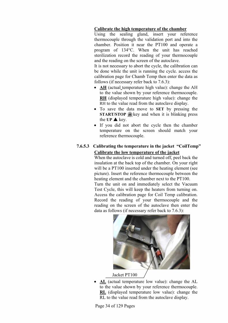
7.6.5.3 Calibrating the temperature in the jacket “CoilTemp”
Calibrate the low temperature of the jacket When the autoclave is cold and turned off, peel back the
insulation at the back top of the chamber. On your right will be a PT100 inserted under the heating element (see picture). Insert the reference thermocouple between the heating element and the chamber next to the PT100.
Turn the unit on and immediately select the Vacuum Test Cycle, this will keep the heaters from turning on. Access the calibration page for Coil Temp calibration. Record the reading of your thermocouple and the reading on the screen of the autoclave then enter the data as follows (if necessary refer back to 7.6.3):
AL (actual temperature low value): change the AL to the value shown by your reference thermocouple. RL (displayed temperature low value): change the RL to the value read from the autoclave display.
Jacket PT100
Page 35 of 129 Pages
To save the data move to SET by pressing the START/STOP key and when it is blinking press the UP key.
Now the jacket temperature on the screen should match your reference thermocouple.
Calibrate the high temperature of the chamber wall Peel back the insulation at the back top of the chamber.
On your right will be a PT100 inserted under the heating element (see picture). Insert the reference thermocouple between the heating element and the chamber next to the PT100.
Select a cycle of 134°C and wait for the autoclave-preheating icon to go off the screen. Access the calibration page for Coil Temp calibration. Record the reading of your thermocouple and the reading on the screen of the autoclave then enter the data as follows (if necessary refer back to 7.6.3): AH (actual temperature high value): change the AH
to the value shown by your reference thermocouple. RH (displayed temperature high value): change the RH to the value read from the autoclave display.
To save the data move to SET by pressing the START/STOP key and when it is blinking press the UP key.
Now the jacket temperature on the screen should match your reference thermocouple.
7.6.5.4 Calibrating the pres sure in the steam generato r
“GenPress”
Calibrate the low pressure of the steam generator When the unit is off and the steam generator is cold and
there is no pressure in it, attach your reference pressure gauge to the calibration port on the generator manifold (see picture). Turn the unit on and immediately select the Vacuum Test Cycle, this will keep the heaters from turning on. Access the calibration page for GenPress calibration. Record the reading of your reference pressure gauge and the pressure reading for the generator on the screen of the autoclave then enter the data as follows (if necessary refer back to 7.6.3):
AL (actual pressure low value): change the AL to the value shown by your reference pressure gauge.
RL (displayed pressure low value): change the RL to the value read from the autoclave display.
To save the data move to SET by pressing the START/STOP key and when it is blinking press the UP key.
The steam generator pressure on the screen should match your reference gauge.

Page 36 of 129 Pages
Calibrate the high pressure of the steam generator When the unit is off and the steam generator is cold and
there is no pressure in it, attach your reference pressure gauge to the calibration port on the generator manifold (see picture). Select a program of 134°C the generator will begin to heat. When the unit has reached the ready state record the reading of your gauge and the reading for the generator on the screen of the autoclave.
Access the calibration page for GenPress then enter the data as follows (if necessary refer back to 7.6.3): AH (actual pressure high value): change the AH to
the value shown by your reference pressure gauge. RH (displayed pressure high value): change the RH to the value read from the autoclave display.
To save the data move to SET by pressing the START/STOP key and when it is blinking press the UP key.
The steam generator pressure on the screen should match your reference gauge.
Generator Calibration port

Page 37 of 129 Pages
7.7 Setting the Clock
This directory enables the operator to set the time and date. The SET CLOCK screen is displayed when entering the SET CLOCK
directory:
When entering the directory the curser will be blinking on the "hour"
digit.
The time is displayed in the upper row in the form “hh:mm:ss”. The hour range is 24 hour (i.e. from “0” to “24”).
The date is displayed in the lower row in the form “DD:MM:YYYY”.
1. To increase or decrease the time or the date use the UP and DOWN keys.
2. To move the curser from one digit to another press the START/STOP key.
3. After changing the time and the date move the curser to “SAVE”.
4. Confirm the new time and date by pressing the UP key. While the new time and date are being saved the following screen is displayed:
5. After saving is completed, the SET CLOCK screen is displayed again, move the cursor to EXIT and press UP to return to the previous MENU screen.
6. The printer will print the date in the format DD:MM:YYYY if the chamber temperature is being displayed in ˚C. It will print the date in the format MM:DD:YYYY if the chamber temperature is being displayed in ˚F.”

Page 38 of 129 Pages
7.8 Printer Test
This option checks the good functioning of the printer. 1. Select "Printer Test" as described in section 7.1 "Menu". 2. Press the START/STOP key to perform the Printer Test. 3. Check that the message “Printer Test” is written on the paper.

Page 39 of 129 Pages
7.9 Language
THIS OPTION IS NOT AVAILABLE YET
Page 40 of 129 Pages
7.10 History
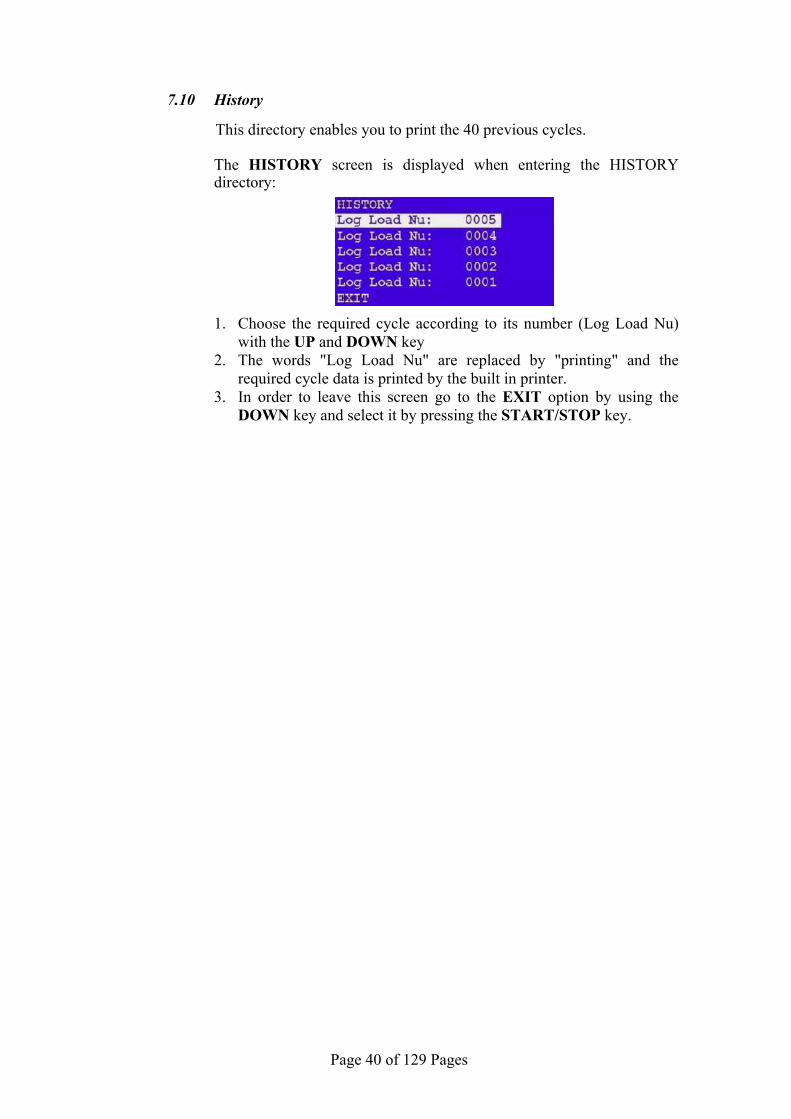
This directory enables you to print the 40 previous cycles. The HISTORY screen is displayed when entering the HISTORY
directory: 1. Choose the required cycle according to its number (Log Load Nu)
with the UP and DOWN key 2. The words "Log Load Nu" are replaced by "printing" and the
required cycle data is printed by the built in printer. 3. In order to leave this screen go to the EXIT option by using the
DOWN key and select it by pressing the START/STOP key.
Page 41 of 129 Pages
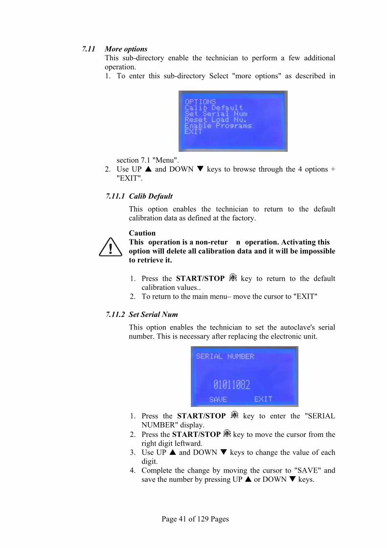
7.11 More options This sub-directory enable the technician to perform a few additional
operation. 1. To enter this sub-directory Select "more options" as described in
section 7.1 "Menu". 2. Use UP and DOWN keys to browse through the 4 options +
"EXIT".
7.11.1 Calib Default This option enables the technician to return to the default calibration data as defined at the factory.
Caution This operation is a non-retur n operation. Activating this option will delete all calibration data and it will be impossible to retrieve it.
1. Press the START/STOP key to return to the default
calibration values.. 2. To return to the main menu– move the cursor to "EXIT"
7.11.2 Set Serial Num
This option enables the technician to set the autoclave's serial number. This is necessary after replacing the electronic unit.
1. Press the START/STOP key to enter the "SERIAL NUMBER" display.
2. Press the START/STOP key to move the cursor from the right digit leftward.
3. Use UP and DOWN keys to change the value of each digit.
4. Complete the change by moving the cursor to "SAVE" and save the number by pressing UP or DOWN keys.

Page 42 of 129 Pages
7.11.3 Reset Load Nu. This option enables the technician to reset the autoclave's load number. Caution This operation is a non-retur n operation. Activating this option will reset the load num ber to "0" and it w ill be impossible to return to the previous setting it. 1. Press the START/STOP key to reset the load number. 2. The load number will reset to "0" and the following will be
displayed.
7.11.4 Enable Programs
This option enables the technician to choose the programs that will be enabled or disabled. When entering this option the following is displayed.
1. Use UP and DOWN keys to browse through the
programs. 2. The number on the right side of the program name defines the
status of the program. 1 – enabled 0 – disabled
Press the START/STOP key to switch between 1 and 0. 3. It is possible to enable or disable any program, but at least
one program must remain enabled. 4. To exit this option press both UP and DOWN keys
simultaneously.

Page 43 of 129 Pages
8 RESETTING THE AUTOCLAVE
Whenever it becomes necessary to restore the system to normal operation, the system must be reset. This will remove corrupted data from memory and restore a healthy program. On occasion other situations require that a reset be performed, they are as follows: When the machine is operated for the first time. If the machine has been sitting unused for a long period of time.
To reset the system proceed as follows:
Turn-off the main power switch on the right side of the autoclave. Turn-on the main switch while pressing and holding the DOWN key
until the message “RESET DONE!!!” is displayed. This will not erase any settings or history.

Page 44 of 129 Pages
9 MAINTENANCE AND REPLACEMENT PROCEDURES
9.1 Preliminary Operations for Each Technician Call
1. In order to mainta in efficient service, the technician must perform the following:
1. Inspect and clean if needed, the following: Chamber, trays and trays holder (see Maintenance
Instructions in the Operator’s Manual). Filters. Seats and plungers of the solenoid valves (see sec. 9.21). Water level electrode in the generator (see sec. 9.8). Water reservoir(see sec. 9.27). Steam generator (including descaling) (see sec. 9.32).
2. Visual inspection for leaks or corrosion in the piping elements 3. Tightening loose screws and piping joints. 4. Visual inspection of the wiring. 5. Calibration and logging the calibration of the temperature and
pressure.
2. After completing the work, the technician must perfo rm the following cycles:
1. A Wdry 134 cycle with out load
2. A Vacuum Test
3. A B&D Test.
Note: The warranty does not cover cleaning or maintenance. These procedures
are the responsibility of the equipment owner.”
Page 45 of 129 Pages
9.2 Safety tests after repair ATTENTION! After every repair or dismantling of the enclosure, the technician
should perform the following two electrical safety tests.
1. Enclosure Leakage Current Test. Every autoclave should pass this test as follows:
1. Connect the electrical cord to the autoclave. DO NOT plug into the power outlet.
2. Turn on the main switch on the right side of the autoclave. 3. Short-circuit the L and L pins on the cord's plug. 4. Connect the Short-circuit pins to the L pole on the Megger. 5. Connect the GND pin to the GND pole on the Megger. 6. Impose an electrical potential of 1000V±10% on the tested
autoclave. The insulation resistance should be at least 2 MΩ. The test is successful if there was no leakage.
2. Protective Earth Impedance Test 1. Connect the grounding pin of the power cord plug to one pole
of an Ohmmeter. 2. Connect any other metallic part (preferable – the metallic part
of the locking screw) to the second pole of the Ohmmeter. 3. The resistance should not exceed 0.3 Ω.
After performing these tests, the Service Engineer should complete and sign the Work Order.

Page 46 of 129 Pages
9.3 Dismantling the Outer Covers of the Autoclave Caution! Before starting, disconnect the instrument from the po wer source
and ensure that there is no pressure in the autoclave. Allow the autoclave to cool before removing outer covers.
1. Unscrew the screws (2) holding the upper cover (1). 2. Remove the upper cover. 3. Unscrew the screws (4) holding the side covers (3). 4. Remove the side covers (3). 5. Disconnect the air filter (6) from the air filter cover (7). 6. Unscrew the screws (5) holding the rear covers (8). 7. Remove the rear cover (8). 8. Remove the grounding wires from the rear cover.
8 7
4
3
6
1
2
5

Page 47 of 129 Pages
9.4 Replacing the Safety Valve Caution! Before starting, be sure that the electric cord is disconnected and that
there is no pressure in the chamber or generator. Allow the autoclave to cool before removing outer covers.
The safety valve is installed to protect the system from over pressurizing should all the electrical controls fail.
1. Take off the autoclave cover (see para. 9.3 “Removing the
Autoclave’s Outer Covers”). 2. Remove the water reservoir cover. 3. Unscrew the safety valve (2) and remove it from the safety valve
base (1). 4. Replace the valve with a new safety valve (install only an original
equipment replacement!). Use liquid thread seal on the threads to seal it. Tighten the safety valve to prevent leaking.
5. To check the new safety valve, perform the following:
6. Operate the sterilization cycle according to the manual but with no
instruments. 7. Allow a pressure of approximately 300 kPa (29-psig) to build up in
the generator and the chamber. 8. Remove water reservoir cover. 9. Pull the ring (4) of each safety valve in turn using a tool, i.e.
screwdriver, hook etc. (3). Pull the safety valve ring for 2 seconds. Be careful not to burn your hands.
10. Press the STOP key to stop operation, and exhaust steam from chamber.
11. Wait until pressure decreases to zero, only then can the door be opened.
43
No. Description 1 Safety valve base 2 Safety valve 3 Pulling device 4 Pressure relief ring
1 2

Page 48 of 129 Pages
9.5 Replacing chamber heater
Be careful not to bend the tubing or over-tighten with tie wraps. Kinking the tubing will weaken that area of the tube and it will leak. Replace any tubes that become damaged.
1. Perform this procedure only when the unit is cool and there is no
pressure in the chamber. 2. Unplug the unit 3. Drain the steam generator using a 6 mm Allen wrench to remove
the bottom plug. 4. Drain both reservoirs 5. Unscrew the screw holding the cooler to the right rear vertical
frame support. 6. Remove the left and right top frame supports. 7. Disconnect the chamber pressure transducer tubing from top rear
chamber manifold. Move the transducer and tubing out of your work area.
8. Disconnect the air valve 52 tubing from the top rear chamber manifold.
9. Disconnect tubing from the air check valve on the top rear chamber manifold.
10. Remove the generator pressure transducer from generator manifold. Move the transducer and tubing out of your work area.
11. Remove the safety valve tube from generator manifold and also from safety valve at the reservoir.
12. Remove steam generator tube from steam valve 93. 13. Remove generator water inlet tube from water valve 21 at the
check valve. 14. Remove wires from generator pressostat. 15. Remove wire from generator water electrode. 16. Disconnect generator heater wires from both sides of terminal
block on back of valve assembly bracket. 17. Remove three screws holding the Toroidal transformer rear
mounting bracket and lay it back on the counter. 18. Remove the generator cut-off thermostat probe 19. Remove four screws from bottom of chassis holding steam
generator and remove steam generator.

Page 49 of 129 Pages
20. Remove the water tube from the water pump outlet. 21. Remove air filter tube from valve 43. 22. Remove the fast exhaust tube from valve 73. 23. Remove the steam tube from valve 93 at the connector on the back
center of the chamber. 24. Remove the vacuum tube from the top connection of the cooler. 25. Remove two wires from the door switch. 26. Remove three screws holding the valve assembly bracket and
position bracket and valves over reservoirs. 27. Remove the fill tube from the fill cup and move out of the way. 28. Disconnect the two chamber heating element wires. 29. Cut tie wrap holding insulation blanket and discard. 30. Carefully remove insulation blanket. Pulling too hard will tear the
blanket. Be aware the two screws holding the waste reservoir bracket to the chassis my snag the blanket. The rear of the chamber can move sideways slightly to add clearance for removing the blanket.
31. Mark edge of heating element down length of chamber for positioning the replacement.
32. Loosen the four bolts holding the chamber heating element. 33. Remove the chamber temperature sensor and cut-off thermostat
probe. Note their location for reinstallation. 34. Remove completely the four bolts holding the chamber heating
element. 35. Carefully remove the heating element. The rear of the chamber
can move sideways slightly to add clearance for removing the heater.
36. Install the new heating element and follow these steps in reverse to reassemble the unit.
37. When tightening the bolts on the heating element, tighten as tight as possible.
38. When reinstalling the insulation make sure it is tucked in, in all the proper places.
39. When the installation is complete run a cycle to verify proper operation.
40. The steam generator may fail to heat initially due to air pressure in the generator. If this occurs purge the air by opening the generator safety valve.

Page 50 of 129 Pages
9.6 Replacing steam generator heater Caution: Before starting, be sure that the electric cord is disconnected from the
power source and that there is no pressure in the autoclave chamber or steam generator.
Allow the autoclave and the steam generator to cool before removing outer covers.
1. Remove the autoclave cover (see para. 9.3 “Removing the autoclave’s outer covers”).
2. Drain the water from the generator by opening the drain plug. Wait until all the water has drained from the generator (see sec. 9.24).
3. Disconnect the heating element wires from the porcelain connector (1).
4. Remove three screws holding rear mounting bracket and lay it back on the counter.
5. Remove the cut-out thermostat probe from the generator.
6. Remove the heating element from the generator.
7. Install the new heating element using liquid Teflon sealant.
8. Insert the cut-out thermostat probe into the new heating element.
9. Reconnect the heating element wires.
10. Reattach the rear mounting bracket.
11. Run a test cycle.
1

Page 51 of 129 Pages
9.7 Replacing the steam generator cut-off thermostat The autoclave is equipped with a cut-off thermostat, which protects the
steam generator heating element from overheating. Caution Before starting, disconnect the instrument from the power source and
ensure that there is no pressure in the chamber or steam generator. Allow the autoclave to cool before removing outer covers.
1. Remove the rear cover (see para. 9.3 “Removing the autoclave’s outer covers”).
2. Remove three screws holding rear mounting bracket and lay it back on the counter.
3. Remove the probe of cut-out thermostat (2) from the generator. 4. Remove the cut-out thermostat probe from the generator. 5. Unscrew the nut holding the cut-off thermostat (2) to the rear
mounting bracket. 6. Insert the new cut-off thermostat probe into the generator as far as it
will go. Secure the cut-off thermostat with the nut removed earlier. 7. Reattach the rear mounting bracket. 8. Reassemble the rear cover.
No. Description 1 Chamber heater cut-off thermostat
2 Steam generator heater cut-off thermostat
2
1
Page 52 of 129 Pages
9.8 Replacing and cleaning the generator’s water level electrode The electrode that controls the water level of the generator is located in
the rear of the generator. The Electrode performs the following:
a. It protects the heating element by switching it off when there is not enough water in the generator.
b. It maintains the water level in the generator by switching the water pump on and off as required.
To clean or replace the electrode proceed as follows (refer to the picture and the drawings on the next page):
Caution! Before starting, disconnect the instrument from the po wer source
and ensure that there is no pressure in the chamber or the generator.
Allow the autoclave to cool before removing outer covers.
1. Take off the autoclave cover (see para. 9.3 “Removing the Autoclave’s Outer Covers”).
2. Remove the electrical connection from the terminal of the electrode.
3. Unscrew the locking nut and remove the electrode from the top of the housing.
4. Replace the electrode with a new one or reinstall the same electrode after cleaning.
4.1 To clean the electrode, use a damp cloth or sponge. A mild soapy solution may be used, rinse thoroughly. DO NOT use any harsh chemicals
4.2 When installing a new electrode, make sure that the electrode is positioned exactly as described in drawing "water level electrode (see drawing ahead).
5. Tighten the locking nut to prevent any steam or water leakage.
6. Reconnect the electrical wire to the electrode terminal.
7. Turn the autoclave on. The generator will automatically fill with water. Observe that the unit is heating. Wait for the unit to reach 30 psig (44.7 psi 308 kPa), and then check for leaks around the locking nuts.
8. Reassemble the cover.

Page 53 of 129 Pages
WATER LEVEL ELECTRODE
0.16
"-0.
24"
Water level Electrodes
Water level Electrodes

Page 54 of 129 Pages
9.9 Replacing the Drain Valve There are two drain valves on the front of the autoclave. One drains the
mineral free water from the clean reservoir and the other drains the water from the waste water reservoir.
Caution! Before starting, disconnect the instrument from the power source and
ensure that there is no pressure in the autoclave. Allow the autoclave to cool before removing outer covers.
1. Drain the reservoir (See sec "Draining the Reservoirs" in the Operator’s Manual). If the drain is not operational it will be necessary to suction the water out of the reservoir from the top.
2. Remove the autoclave cover (see para. 9.3 “Removing the Autoclave’s Outer Covers”).
3. Remove the right top frame support over the reservoirs.. 4. Remove the metal shroud shielding the electronic components. 5. Remove the drain hose from the inside portion of the drain valve (1). 6. Unscrew the inside nut (6) using a 21mm socket wrench. 7. Remove the drain valve (1) from the panel (7). 8. Install the new valve and reattach the drain tube. Use a tie wrap to
secure the drain tube to the valve. 9. Verify there is no leakage. 10. Replace the metal shroud and right frame support.
7
VLV170-0013 VLV170-0015
1 6
Outside machineInside machine
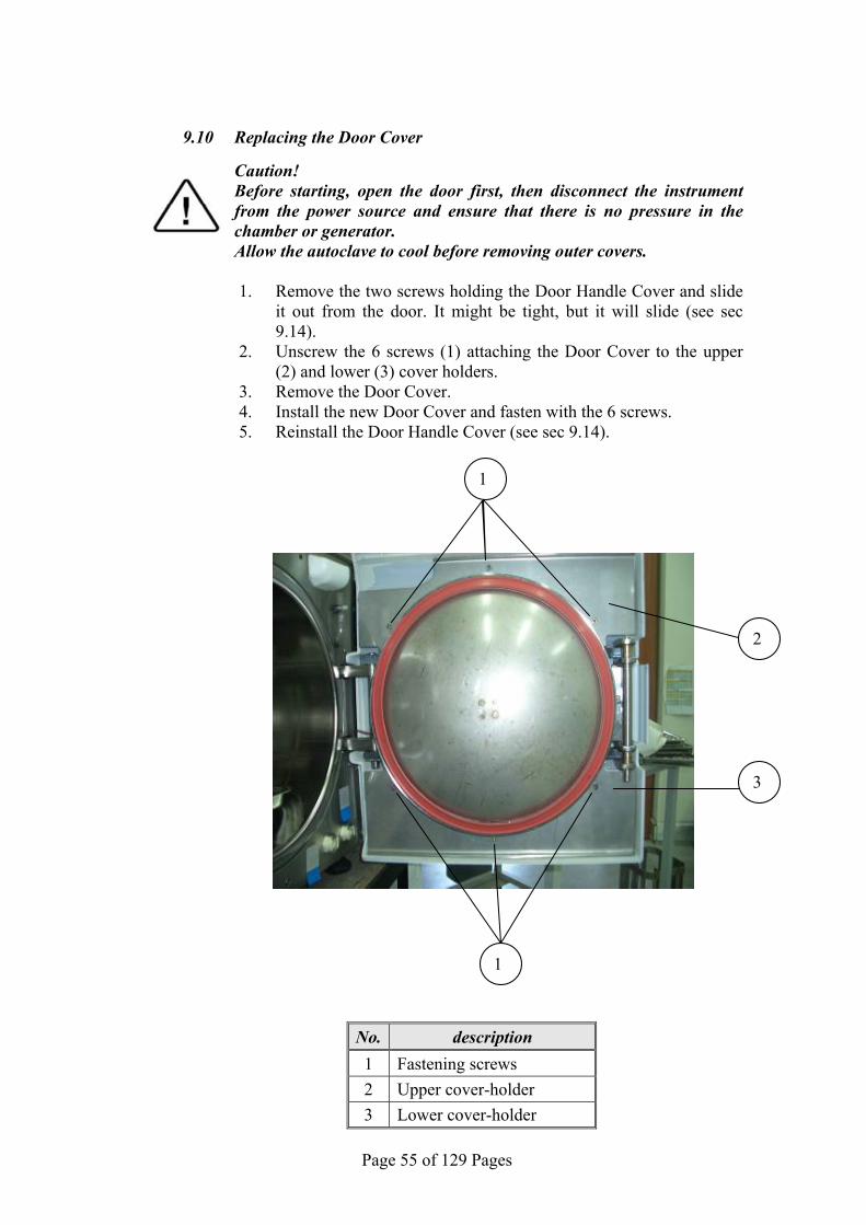
Page 55 of 129 Pages
9.10 Replacing the Door Cover
Caution! Before starting, open the door first, then disconnect the instrument
from the power source and ensure that there is no pressure in the chamber or generator.
Allow the autoclave to cool before removing outer covers.
1. Remove the two screws holding the Door Handle Cover and slide it out from the door. It might be tight, but it will slide (see sec 9.14).
2. Unscrew the 6 screws (1) attaching the Door Cover to the upper (2) and lower (3) cover holders.
3. Remove the Door Cover. 4. Install the new Door Cover and fasten with the 6 screws. 5. Reinstall the Door Handle Cover (see sec 9.14).
No. description 1 Fastening screws
2 Upper cover-holder
3 Lower cover-holder
2
3
1
1

Page 56 of 129 Pages
9.11 Replacing the Front Panel Caution! Before starting, disconnect the instrument from the po wer source
and ensure that there is no pressure in the autoclave. Allow the autoclave to cool before replacing the Panel.
1. Open the printer's door (4). 2. Unscrew the three bottom fastening screws (5). 3. Unscrew the top fastening screw (1). 4. Pull the panel approx. 30 centimeters. 5. Remove the digital card (located on the rear side of the panel – as
per instructions in sec.9.22). 6. Remove the printer (3) (see sec. 9.15 "Replacing the Printer"). 7. Assemble the digital card on the new panel (see sec. 9.22). 8. Assemble the printer on the new panel. 9. Assemble the panel and fasten it to the autoclave with the 4
fastening screws (1 & 5).
3
2
4
1
5

Page 57 of 129 Pages
9.12 Replacing the Printer Door Caution! Before starting, disconnect the instrument from the po wer source
and ensure that there is no pressure in the autoclave. Allow the autoclave to cool before replacing the Printer Door.
1. Open the printer's door (3). 2. Unscrew and remove the 3 screws (2) holding the Printer Door to
the Integral Hinge (1). 3. Remove the Printer Door. 4. Assemble the new Printer Door to the Integral Hinge with the 3
screws (2).
3 1 2

Page 58 of 129 Pages
9.13 Replacing the Door Handle Caution! Before starting, ensure that there is no pressure in the autoclave. Allow the autoclave to cool before replacing the Door Handle. Do not disconnect the electric po wer, since disconnecting the po wer
will lock the handle and prevent replacement of the handle.
1. Open the autoclave's door. 2. Remove the two screws holding the Door Handle Cover and slide it
out from the door. It might be tight, but it will slide (see sec 9.14). 3. Remove the Door Handle by pulling it in the direction of the arrow
(1). It might be tight, but it will slide out of its holder. 4. Slide the new handle into position. 5. Reinstall the Door Handle Cover (see sec 9.14).
1
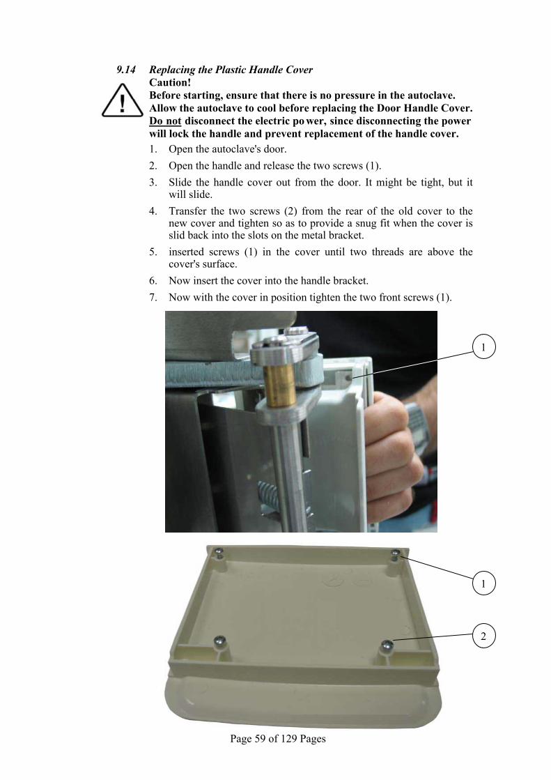
Page 59 of 129 Pages
9.14 Replacing the Plastic Handle Cover Caution! Before starting, ensure that there is no pressure in the autoclave. Allow the autoclave to cool before replacing the Door Handle Cover. Do not disconnect the electric po wer, since disconnecting the power
will lock the handle and prevent replacement of the handle cover.
1. Open the autoclave's door.
2. Open the handle and release the two screws (1).
3. Slide the handle cover out from the door. It might be tight, but it will slide.
4. Transfer the two screws (2) from the rear of the old cover to the new cover and tighten so as to provide a snug fit when the cover is slid back into the slots on the metal bracket.
5. inserted screws (1) in the cover until two threads are above the cover's surface.
6. Now insert the cover into the handle bracket.
7. Now with the cover in position tighten the two front screws (1).
1
1
2

Page 60 of 129 Pages
9.15 Replacing the Printer
Caution! Before starting, disconnect the in strument from the po wer source
and ensure that there is no pressure in the chamber or the generator.
Allow the autoclave to cool before removing outer covers.
1. Remove the autoclave cover (see sec. 9.3 “Dismantling the Outer Covers of the Autoclave”).
2. Disconnect the cable (1) from the back of the printer. 3. Unscrew the two screws (3) attaching the fastening bracket (4) to
the printer. 4. Remove the printer. 5. Set the dip switches on the new printer, located on the back side of
the printer, as follows:
6. Insert the new printer into its frame. 7. Assemble the mounting bracket (4) to the printer (2) with the two
screws (3) and verify that it is securely in position. 8. Connect the cable (1) to the printer. 9. Verify connection of power by performing a printer test (see sec.
7.8). 10. Run a cycle and verify that the printer operates correctly.
5, 6, 7 down
1, 2, 3, 4, up
8, 9 up
10 down
1
3
2
4
No. Cat. No. Description
1 CTP201-0127 Cable, Printer, DPU-30, 30cm, 34p
2 THE002-0022 Printer, DPU-30, Seiko

Page 61 of 129 Pages
9.16 Replacing the Door Switch
Caution! Before starting, disconnect the instrument from the po wer source
and verify that there is no pressure in the chamber or the generator. Allow the autoclave to cool before removing outer covers.
1. Remove the autoclave top and left covers (see para. 9.3 “Dismantling the Outer Covers of the Autoclave”).
2. Open the door 3. Unscrew the 2 screws (1) holding the door switch adapter (5) on
the front panel of the autoclave. 4. Disconnect the 2 wires (2, 3) from the door switch (4). 5. Remove the door switch from the autoclave.
6. Release nut (6) and unscrew the door switch (4) from the door switch adapter (5).
7. Assemble the new door switch to the adapter. Verify that the wheel protrudes (A) approx. 0.37"-0.38" (9.5-10mm) from the adapter (5) and tighten nut (6).
8. Assemble the door switch with its adapter to the front panel. Do not tighten the two screws (1).
9. Perform final adjustment of the microswitch using a GO-NO GO gauge (P/N JIG411-0102) as follows:
1 3
6
2 5
4 A
4
5

Page 62 of 129 Pages
9.1 Insert the GO side (8) of the gauge (11) between the wheel (7) of the microswitch and the door locking hooks (9) while pressing the gauge to the hooks. Verify that you hear a "click" indicating the closing of the switch.
9.2 Insert the NO GO side (10) of the gauge (11) between the wheel (7) of the microswitch and the door locking hooks (9) while pressing the gauge to the hooks. Verify that you DO NOT hear the "click" indicating the closing of the switch.
9.3 If these two conditions are fulfilled, dimension "A" is correct, tighten screws (1).
9.4 If dimension "A" is not correct, remove the microswitch from the panel, turn the adapter 1/2 a turn clockwise or counterclockwise as required and reassemble it to the panel.
9.5 Repeat steps 9.1-9.4. 10. Reconnect the 2 wires (2, 3) to the door switch. Verify that one
wire is connected to screw no. 1 ("COM" - marked on the switch) and the other wire is connected to screw no. 3 ("NO" marked on the switch).
Make sure that the door switch is installed correctly (the wheel of the microswitch is parallel to the floor)!
Check that the operational message “Door is Open" is displayed when the door is opened and that the messag e disappears when the door is closed.
7 8 9 11 10
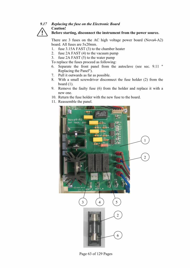
Page 63 of 129 Pages
9.17 Replacing the fuse on the Electronic Board Caution! Before starting, disconnect the instrument from the power source.
There are 3 fuses on the AC high voltage power board (Nova4-A2) board. All fuses are 5x20mm. 1. fuse 3.15A FAST (3) to the chamber heater 2. fuse 2A FAST (4) to the vacuum pump 3. fuse 2A FAST (5) to the water pump
To replace the fuses proceed as following: 6. Separate the front panel from the autoclave (see sec. 9.11 "
Replacing the Panel"). 7. Pull it outwards as far as possible. 8. With a small screwdriver disconnect the fuse holder (2) from the
board (1). 9. Remove the faulty fuse (6) from the holder and replace it with a
new one. 10. Return the fuse holder with the new fuse to the board. 11. Reassemble the panel.
4 53
6
2
1
2
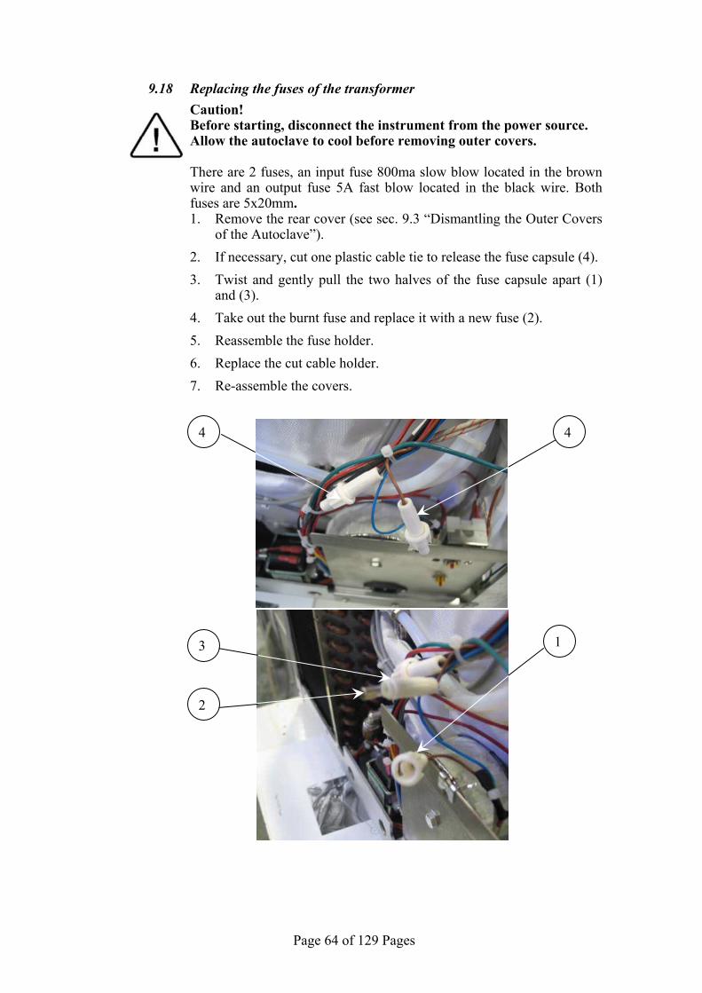
Page 64 of 129 Pages
9.18 Replacing the fuses of the transformer
Caution! Before starting, disconnect the instrument from the power source. Allow the autoclave to cool before removing outer covers. There are 2 fuses, an input fuse 800ma slow blow located in the brown
wire and an output fuse 5A fast blow located in the black wire. Both fuses are 5x20mm. 1. Remove the rear cover (see sec. 9.3 “Dismantling the Outer Covers
of the Autoclave”).
2. If necessary, cut one plastic cable tie to release the fuse capsule (4).
3. Twist and gently pull the two halves of the fuse capsule apart (1) and (3).
4. Take out the burnt fuse and replace it with a new fuse (2).
5. Reassemble the fuse holder.
6. Replace the cut cable holder.
7. Re-assemble the covers.
3
2
1
4 4

Page 65 of 129 Pages
9.19 Replacing the water pump Caution! Before starting, disconnect the instrument from the power source. Allow the autoclave to cool before removing outer covers.
1. Empty the water reservoir (See Draining the Water Reservoir in the Operator’s Manual).
2. Remove the autoclave rear cover (see sec. 9.3 “Dismantling the Outer Covers of the Autoclave”).
3. Remove the three screws holding the electrical socket rear mounting bracket and set it aside.
4. Disconnect the wires from the pump. 5. Disconnect the piping from the pump. 6. Remove the pump (7) from the rubber shock absorbers (1).
If the rubber shock absorbers are damaged, replace them. 7. Replace the damaged pump with a new pump. 8. Reconnect wiring and piping. 9. Reassemble the electrical socket bracket. 10. Reassemble the rear cover. 11. Refill the mineral-free water reservoir. 12. Turn on the autoclave and verify it operates correctly.
No. Description Cat. No.
1 Rubber shock absorber SKR203-0006
2 Fitting 5/16”x1/8” (straight) FIT100-0803
3 Screw
Fas
teni
ng th
e sh
ock
abso
rber
BOL191-0142
4 Nut NUT192-0155
5 washer NUT193-0283
6 Spring washer NUT193-0317
7 ULKA water pump PUM055-0019
7
2
1
3
6
4
5
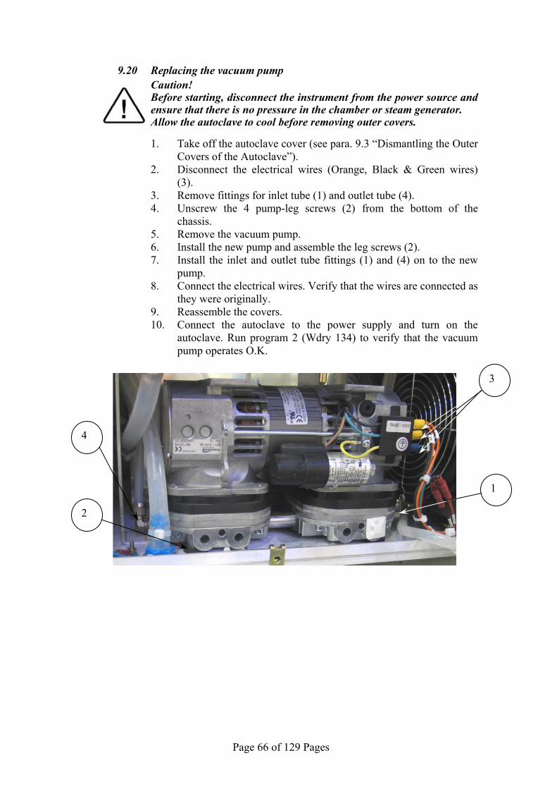
Page 66 of 129 Pages
9.20 Replacing the vacuum pump
Caution! Before starting, disconnect the instrument from the power source and
ensure that there is no pressure in the chamber or steam generator. Allow the autoclave to cool before removing outer covers.
1. Take off the autoclave cover (see para. 9.3 “Dismantling the Outer Covers of the Autoclave”).
2. Disconnect the electrical wires (Orange, Black & Green wires) (3).
3. Remove fittings for inlet tube (1) and outlet tube (4). 4. Unscrew the 4 pump-leg screws (2) from the bottom of the
chassis. 5. Remove the vacuum pump. 6. Install the new pump and assemble the leg screws (2). 7. Install the inlet and outlet tube fittings (1) and (4) on to the new
pump. 8. Connect the electrical wires. Verify that the wires are connected as
they were originally. 9. Reassemble the covers. 10. Connect the autoclave to the power supply and turn on the
autoclave. Run program 2 (Wdry 134) to verify that the vacuum pump operates O.K.
3
4
1
2

Page 67 of 129 Pages
9.21 Replacing the Plunger or Coil of the 1/4" Solenoid Valve Caution! Before starting, disconnect the instrument from the po wer source
and ensure that there is no pressure in th e chamber or steam generator.
Allow the autoclave to cool before removing outer covers.
1. Take off the autoclave top cover (see para. 9.3 “Removing the Autoclave’s Outer Covers”).
2. Remove nut (3) and washer (2).
3. Remove the coil (1).
4. Unscrew the plunger and replace it with a new kit. The plunger kit consists of the plunger housing (6) and the plunger & spring (5).
5. Using a magnifying glass, inspect the seat in the valve base for chips or cracks. If any are found the base will need to be replaced.”
6. Reassemble the coil (1) the nut (3) and the washer (2). If a new coil is needed then unplug the electrical connector (4) from the old coil and plug it into the new coil.
7. Reassemble the coil (1) and the nut (3).
8. Re-install the autoclave’s cover.
5 6
2 1 3 4

Page 68 of 129 Pages
9.22 Replacing the Electronic Boards Caution! Before starting, disconnect the instrument from the po wer source
and ensure that there is no pressure in the chamber. Allow the autoclave to cool before removing outer covers. See drawings "Nova4-D2" and "Nova4-A2 on the following pages to
assist in locating connectors marked by JP.
9.22.1 Removing the Front Panel Assembly 1. Remove the control panel assembly (see sec 9.11
“Replacing the Front Panel;”).
2. Disconnect the flat cable (7) from the flat cable socket (1) at the top of the big board (Nova4-D2).
3. Disconnect all the connectors along the outside edge of the big board (Nova4-D2), JP11, JP2, JP3, JP1, JP12, JP13, JP15, making note of their location.
4. Disconnect the GND wire at the top of the Nova4-D2 board
5. Disconnect the connectors at JP11, JP9, JP12, JP15, JP7, JP8 and JP6 on the small board (Nova4-A2).
6. Disconnect the small green wire at the bottom right
7. Lay the front panel on a table with the keyboard down.
9.22.2 Replacing the "Nova4-A2" (small) board
1. Disconnect wires from JP2, JP3, JP4, JP5 (6), making
sure to note the location of each wire on the circuit board.
2. Disconnect connector JP10 (4).
3. Unscrew the 4 screws (3) attaching the small board (5) to the big board (2).
4. Remove the small board.
5. Check the isolation sheet that is placed under the board. Replace if damaged.
6. Place the new board and fasten it with the 4 screws (3).
7. Connect the connector JP10 and the wires JP2-JP5.
8. Return the control unit to the autoclave and reconnect the wires and connectors following, in reverse order, the instructions in sec 9.22.1.
9. Re-assemble the control panel to the autoclave

Page 69 of 129 Pages
1
2
3
4
5
3
6
3
3
7
8
Assembled Nova4-D2 and Nova4-A2 Boards

Page 70 of 129 Pages
Nova4-A2 Board
JP2
JP11 JP9 JP7 JP8
JP3
JP4
JP5
JP6
JP10
JP12 JP15
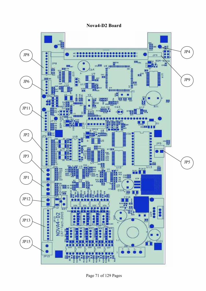
Page 71 of 129 Pages
Nova4-D2 Board
JP4 JP8
JP3
JP6
JP12
JP13
JP15
JP1
JP11
JP2
JP9
JP5

Page 72 of 129 Pages
9.22.3 Replacing the "Nova4-D2" (big) board
1. Disconnect wires from JP2, JP3, JP4, JP5 (6 on previous page) on the Nova4-A2 board. Making sure to note the location of each wire on the circuit board.
2. Disconnect connector JP14 (8). 3. Unscrew the 4 screws (3) attaching the small board (5)
to the big board (2). 4. Remove the small board. 5. Check the isolation sheet that is placed under the board.
Replace if damaged. 6. Unscrew the 4 long spacers (9) connecting the small
board to the big board. 7. Unscrew the 2 screws (12) connecting the big board to
the plastic panel (11). Be careful not to lose the grounding terminal (10) fastened by one of the screws.
8. Lift the board slightly and disconnect the keypad flat cable (14) from its connector (13) on the rear side of the board.
9. Replace the big board with a new board. 10. Reassemble by following steps 1 thru 8 in reverse order.
13
14
9
12
10 11

Page 73 of 129 Pages
9.23 Replacing the switch Caution! Before starting, disconnect the instrument from the po wer source
and ensure that there is no pressure in the chamber. Allow the autoclave to cool before removing outer covers.
1. Remove the control electronic boards (see para. 9.22 "Replacing the Electronic Boards").
2. Disconnect the wires (1) from the switch (3). Log which wire is connected to each leg (2) of the switch.
3. Press the switch's fasteners (5) and push the switch inwards to release it from its seat on the panel (4).
4. Remove the switch and replace it with a new one. Pay attention to the switch's position. The "0" on the switch must be opposite the "0" in the plastic panel and the "|" on the switch must be opposite the "|" on the panel.
5. Connect the wires to the switch verifying that the wires are reconnected in the same positions as they were removed in instruction #2.
6. Place the Nova4-D2 board on the panel and reconnect the keypads flat cable to the board.
7. Reassemble the electronic boards according to para. 9.22.
21
3
4
5

Page 74 of 129 Pages
9.24 Draining the generator Caution! Before starting, disconnect the instrument from the po wer source
and ensure that there is no pressure in th e chamber or steam generator.
Allow the autoclave to cool before draining the generator. 1. The generator’s drain plug is located under the autoclave on the left
side. In order to drain the generator it will be necessary to position the autoclave so it is partially hanging over the edge of the counter. CAUTION when attempting to drain the generator make sure the autoclave is well supported and will not fall.
2. Place a vessel under the autoclave to collect the drain water. 3. Unscrew the drain plug, using a 6mm allen wrench.
4. If the water does not drain out easily then pull on the ring of the generator safety valve to break the vacuum in the generator.”
5. After draining the water, reassemble the drain plug. 6. Move the autoclave back to its leveled position, reconnect it to the
power source and turn the autoclave on. 7. Check and verify that the generator is filled with water and that the
plug does not leak.
1

Page 75 of 129 Pages
9.25 Emergency Door Opening Caution! Before starting, disconnect the instrument from the power source and
ensure that there is no pressure in the autoclave.
Caution! Keep hands and face away from the safety valve to avoid being burned
by hot steam.”
9.25.1 Decreasing the pressure Since the autoclave is not equipped with an analogue pressure
gauge, and the display is off (no electrical power), it is recommended to wait approximately one hour to verify that the pressure and temperature have decreased to ambient conditions.
If it is required to open the door urgently, decrease the pressure by opening both, the chamber's and generator's safety valves as follows. The safety valves are located in the mineral-free water reservoir.
A. ASME-approved type safety valve
1. Remove water reservoir cover (1). 2. Pull the ring (4) of the safety valve using a tool, i.e.
screwdriver, hook etc. (3). Pull the safety valve ring until steam ceases to escape from the safety valve. Be careful not to burn your hands.
1
2 43
No. Description 1 water reservoir cover 2 Safety valve 3 Pulling device 4 Pressure relief ring

Page 76 of 129 Pages
B. PED-approved type safety valve
1. Remove the water reservoir cover.
2. Turn the pressure relief nut clockwise until steam ceases to escape from the safety valve.
Attention: Use protective gloves in order not to burn your hands with the hot steam.
9.25.2 Opening the door
1. Insert a 2 mm (0.08") metal pin (1) into the hole (2)
located above the door opening handle (3).
2. Press the pin downwards and, simultaneously open the door by pulling the door handle (3) in the direction of the arrow (4).
No. Description 1 Water reservoir cover 5 Safety valve 6 Pressure relief nut
5 6
1
2
4
3
Page 77 of 129 Pages
9.26 Replacing the water reservoirs
Caution! Before starting, disconnect the instrument from the power source and
ensure that there is no pressure in the autoclave.
Note: The following instructions refer to both, the mineral-free water
reservoir and to the waste-water reservoir.
1. Drain the water reservoir (See sec "Draining the Reservoirs" in the Operator’s Manual).
2. Remove the right, rear and top covers of the autoclave (see para. 9.3 "Dismantling the Outer Covers of the Autoclave").
3. Unscrew the screws (4) holding the cooler to the right rear vertical frame support and bottom frame.
4. Unscrew screws (1 & 2) and remove the right top frame support (10).
5. Disconnect the relevant cable terminals (3 or 9) from the water level electrodes of the reservoir to be removed.
6. Disconnect the tubing and fittings (5, 6, 7, 8 etc.) from the bottom and top of the reservoir to be replaced.
7. Pull the reservoir straight up and out of the machine. 8. Insert the new reservoir and follow the steps in this section in the
reverse order to reassemble the unit.

Page 78 of 129 Pages
5
3
4
6
2
10
9
7
8
1

Page 79 of 129 Pages
9.27 Cleaning the water reservoirs
Caution! Before starting, disconnect the instrument from the power source and
ensure that there is no pressure in the autoclave.
Note: The following instructions refer to both, the mineral-free water
reservoir and to the waste-water reservoir. 1. Drain the water reservoir(See sec "Draining the Reservoirs" in the
Operator’s Manual). 2. Remove the top, right and rear covers of the autoclave (see para.
9.3 "Dismantling the Outer Covers of the Autoclave"). 3. Unscrew the screw (3) holding the cooler to the right rear vertical
frame support. 4. Unscrew screws (1 & 2) and remove the right top frame support
(6). 5. Remove any clips holding the reservoir cover. 6. Remove the top cover of the reservoir. 7. Clean the inside of the reservoir by wiping with a clean cloth. 8. Clean the water level electrodes (connected to 4, 5) inside the
reservoir with a soft cloth. 9. Verify the electrode terminals (4, 5) are connected firmly to the
electrodes. 10. Follow the steps in this section in the reverse order to reassemble
the unit. Be sure to reattach clips to the waste-water reservoir cover.
4 3
2
6
5
1

Page 80 of 129 Pages
9.28 Replacing the cut-of thermostat for the Chamber Heater These instructions refer to pictures on the following page.
1. Perform this procedure only when the unit is cool and there is no pressure in the chamber.
2. Unplug the unit
3. Drain both reservoirs
4. Unscrew the screw holding the cooler to the right rear vertical frame support.
5. Remove the left (15) and right (16) top frame supports.
6. Disconnect the chamber pressure transducer tubing (10) from top rear chamber manifold (8). Move the transducer and tubing out of your work area.
7. Disconnect the air valve 52 tubing (11) from the top rear chamber manifold (8).
8. Disconnect tubing (9) from the air check valve on the top rear chamber manifold
9. Remove three screws (7, 13, 14) holding the valve assembly bracket (12) and move the assembly down to give clearance for removing the insulation blanket.
10. Cut tie wrap holding insulation blanket and discard.
11. Carefully move the insulation blanket (5) to expose the cut-off thermostat sensor (6).
12. Loosen the two bolts (18) holding the section of the chamber heating element (17) that secures the temperature sensor and cut-off thermostat.
13. Remove the chamber cut-off thermostat probe.
14. Trace the cut-off thermostat tubing back to the cut-off thermostat control box (2).
15. Remove the two wires on the control box
16. Unscrew the nut (1) holding the control box to the mounting plate (3).
17. Install the new cut-off thermostat and follow these steps in reverse to reassemble the unit. Position the probe as shown in the picture (6).
18. When tightening the bolts on the heating element, tighten as tight as possible.
19. When reinstalling the insulation make sure it is tucked in, in all the proper places.
20. When the installation is complete run a cycle to verify proper operation
21. The steam generator may fail to heat initially due to air pressure in the generator. If this occurs purge the air by opening the generator safety valve.

Page 81 of 129 Pages
16
14
15 7
13
12
17
18 5
6
1
2
3
11
10
9
8
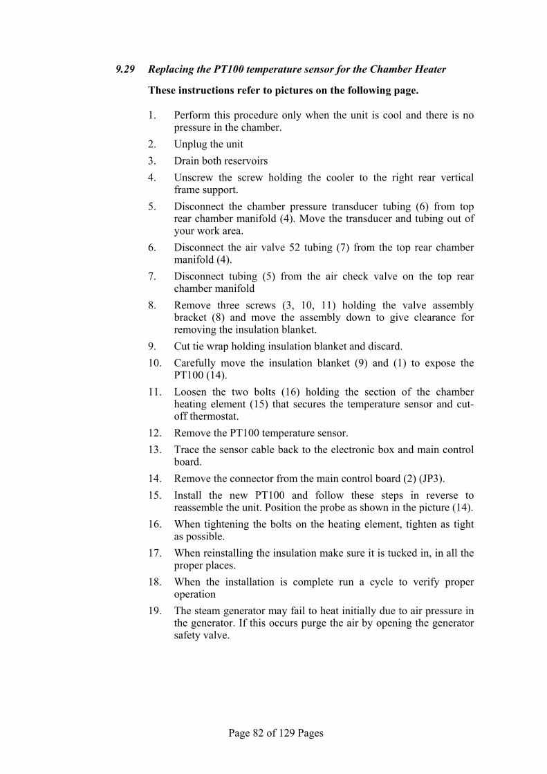
Page 82 of 129 Pages
9.29 Replacing the PT100 temperature sensor for the Chamber Heater These instructions refer to pictures on the following page.
1. Perform this procedure only when the unit is cool and there is no pressure in the chamber.
2. Unplug the unit
3. Drain both reservoirs
4. Unscrew the screw holding the cooler to the right rear vertical frame support.
5. Disconnect the chamber pressure transducer tubing (6) from top rear chamber manifold (4). Move the transducer and tubing out of your work area.
6. Disconnect the air valve 52 tubing (7) from the top rear chamber manifold (4).
7. Disconnect tubing (5) from the air check valve on the top rear chamber manifold
8. Remove three screws (3, 10, 11) holding the valve assembly bracket (8) and move the assembly down to give clearance for removing the insulation blanket.
9. Cut tie wrap holding insulation blanket and discard.
10. Carefully move the insulation blanket (9) and (1) to expose the PT100 (14).
11. Loosen the two bolts (16) holding the section of the chamber heating element (15) that secures the temperature sensor and cut-off thermostat.
12. Remove the PT100 temperature sensor.
13. Trace the sensor cable back to the electronic box and main control board.
14. Remove the connector from the main control board (2) (JP3).
15. Install the new PT100 and follow these steps in reverse to reassemble the unit. Position the probe as shown in the picture (14).
16. When tightening the bolts on the heating element, tighten as tight as possible.
17. When reinstalling the insulation make sure it is tucked in, in all the proper places.
18. When the installation is complete run a cycle to verify proper operation
19. The steam generator may fail to heat initially due to air pressure in the generator. If this occurs purge the air by opening the generator safety valve.

Page 83 of 129 Pages
13
11
12 3
10
9
7
6
5
4
15
14
2
1
16
8
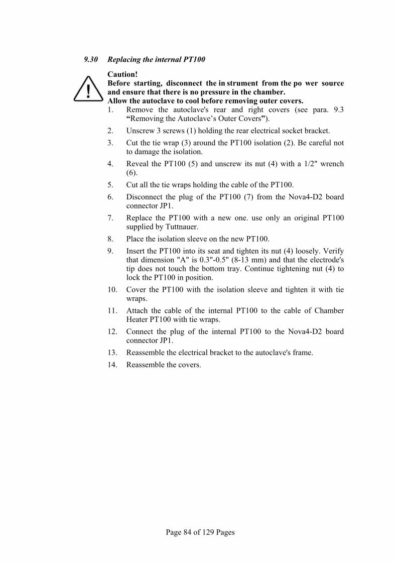
Page 84 of 129 Pages
9.30 Replacing the internal PT100 Caution! Before starting, disconnect the in strument from the po wer source
and ensure that there is no pressure in the chamber. Allow the autoclave to cool before removing outer covers.
1. Remove the autoclave's rear and right covers (see para. 9.3 “Removing the Autoclave’s Outer Covers”).
2. Unscrew 3 screws (1) holding the rear electrical socket bracket.
3. Cut the tie wrap (3) around the PT100 isolation (2). Be careful not to damage the isolation.
4. Reveal the PT100 (5) and unscrew its nut (4) with a 1/2" wrench (6).
5. Cut all the tie wraps holding the cable of the PT100.
6. Disconnect the plug of the PT100 (7) from the Nova4-D2 board connector JP1.
7. Replace the PT100 with a new one. use only an original PT100 supplied by Tuttnauer.
8. Place the isolation sleeve on the new PT100.
9. Insert the PT100 into its seat and tighten its nut (4) loosely. Verify that dimension "A" is 0.3"-0.5" (8-13 mm) and that the electrode's tip does not touch the bottom tray. Continue tightening nut (4) to lock the PT100 in position.
10. Cover the PT100 with the isolation sleeve and tighten it with tie wraps.
11. Attach the cable of the internal PT100 to the cable of Chamber Heater PT100 with tie wraps.
12. Connect the plug of the internal PT100 to the Nova4-D2 board connector JP1.
13. Reassemble the electrical bracket to the autoclave's frame.
14. Reassemble the covers.
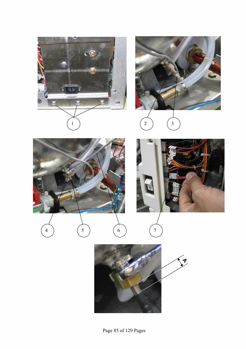
Page 85 of 129 Pages
1 2 3
4 5 6 7
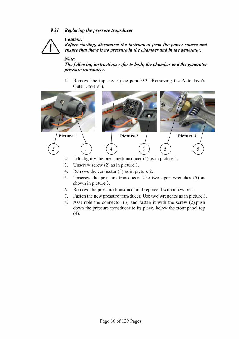
Page 86 of 129 Pages
9.31 Replacing the pressure transducer
Caution! Before starting, disconnect the instrument from the power source and
ensure that there is no pressure in the chamber and in the generator.
Note: The following instructions refer to both, the chamber and the generator
pressure transducer.
1. Remove the top cover (see para. 9.3 “Removing the Autoclave’s Outer Covers”).
2. Lift slightly the pressure transducer (1) as in picture 1. 3. Unscrew screw (2) as in picture 1. 4. Remove the connector (3) as in picture 2. 5. Unscrew the pressure transducer. Use two open wrenches (5) as
shown in picture 3. 6. Remove the pressure transducer and replace it with a new one. 7. Fasten the new pressure transducer. Use two wrenches as in picture 3. 8. Assemble the connector (3) and fasten it with the screw (2).push
down the pressure transducer to its place, below the front panel top (4).
Picture 2
4 3
Picture 3
55
Picture 1
2 1
Page 87 of 129 Pages
9.32 Cleaning the steam generator Caution! Before starting, disconnect the instrument from the power source and
ensure that there is no pressure in the chamber and in the generator.
1. Drain the generator (see sec. 9.24).
2. Remove the generator's heating element (see sec. 9.6).
3. Place a vessel to collect water under the drain opening.
4. Insert a tap-water hose in the heating element opening.
5. Clean the inner part of the generator with water under low pressure.
6. Verify that no water is left in the generator
7. Reinstall the drain plug.
8. Reinstall the heating element (see sec. 9.6).
9. If the generator has an excessive build up of mineral deposits then proceed as follows”
10. Drain the generator see sec 9.24”
11. Disconnect all the piping connected to the generator manifold”
12. Disconnect piping at the front of the generator”
13. Remove the water sensing electrode”
14. Remove the generator heating element see sec 9.6”
15. Remove the four screws holding the generator to the chassis and remove the generator
16. Remover the foam insulation material”
17. Soak the generator in a mineral dissolving solution.”
18. Flush thoroughly with clean water and reinstall following these instructions in reverse order”
Page 88 of 129 Pages
9.33 Replacing the cooler and the cooler's fan Caution! Before starting, disconnect the instrument from the power source and
ensure that there is no pressure in the chamber and in the generator.
1. Drain the waste reservoir. 2. Remove the autoclave's covers (see para. 9.3 “Removing the
Autoclave’s Outer Covers”). 3. Disassemble and remove the right top frame (1). 4. Disconnect the wires (2) from the water level electrodes of the
waste reservoir. 5. Remove the two rear screws from the left top frame. 6. Disconnect the waste water inlet hoses on the left side of the
reservoir and the drain hose (4) below the reservoir. 7. Pull the rear top frame back and remove the waste water reservoir
from the autoclave by pulling it upward. The reservoir bracket supports are slotted so the reservoir will slide straight up.
8. Disassemble the inlet and outlet hoses from the cooler (7). 9. Unscrew 3 screws (8, 9, 10). 10. Remove the cooler (5) with the fan (6) from the autoclave. 11. Disconnect the fan's electrical connector (3). 12. Detach the fan from the cooler. 13. Replace the fan or the cooler as required. 14. Reconnect the fan to the cooler. 15. Connect the fan's electrical connector. 16. Insert the assembled cooler into the autoclave. 17. Assemble the cooler to the autoclave with the 3 screws (8, 9, 10). 18. Reattach the hoses to the inlet and outlet of the cooler (7). Use tie
wraps to secure the hoses. 19. Insert the waste water reservoir into its place. 20. Connect the hoses to the reservoir. Use tie wraps to secure the
hoses. 21. Connect the electrical wires to the water level electrodes. 22. Reassemble the covers.
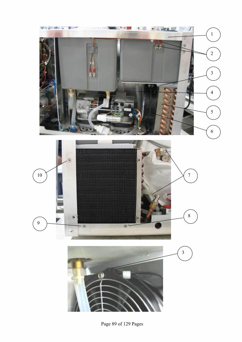
Page 89 of 129 Pages
1
2
3
4
5
6
10
9 8
7
3

Page 90 of 129 Pages
9.34 Testing procedure for the chamber PT100 Caution! Before starting ensure that the autoclave is off and that there is no
pressure in chamber. For items numbering – see pictures on the next page.
1. Prepare a flexible temperature probe with a reading device, a 1/4"BSP sealing nut and a PT100 simulator.
2. Verify using a DVM that the PT100 simulator reads 100Ω at 0˚C and 151.4 Ω at 134˚C
3. Disconnect the connector of the internal PT100 from the electronic board (2) JP1.
4. Connect a PT100 simulator to the socket of the PT100 JP1.
5. Turn on the autoclave and select the Vacuum Test Cycle to keep the unit from heating up.
6. Change the temperature display to ˚C by changing parameter TempInF (see sec 7.2.35) to 0.
7. Set the simulator to 70˚C and verify that the reading on the display is 70˚C Using the PT100 simulator recalibrate if necessary (See sec 7.6).
8. Set the simulator to 134˚C and verify that the reading on the display is 134˚C Using the PT100 simulator recalibrate if necessary (see sec. 7.6).
9. If the readings on the display are correct the electronic system is functional and you can proceed. If the calibration does not align the simulator with the display readout, then replace the Nova4-D2 board.”
10. Disconnect the simulator and reconnect the PT100 (2). 11. Using the sealing nut insert the temperature probe into the
chamber through the Validation port (1) and place it close to the PT100.
12. With the door closed and the Vacuum Test cycle still selected allow the chamber temperature to stabilize.
13. Verify that the Elara display and the independent temperature reading device show the same temperature. Recalibrate if necessary (see sec 7.6).
14. Select and run a 134°C cycle
15. When the pressure has stabilized, verify that the deviation between the reading of the PT100 and the probe does not exceed ±1/2°C.
16. If the deviation is greater than ±1/2˚C then calibrate the Chamber Temperature Sensor. (see sec 7.6).
17. If the calibration is not successful then change the Chamber PT100.

Page 91 of 129 Pages
2 1
Page 92 of 129 Pages
9.35 Testing procedure for the heating element PT100 Caution! Before starting ensure that the autoclave is off and that there is no
pressure in chamber. For items numbering – see pictures on the next page.
1. Prepare a flexible temperature probe with a reading device and a PT100 simulator.
2. Verify using a DVM that the PT100 simulator reads 100Ω at 0˚C and 151.4 Ω at 134˚C.
3. Disconnect the connector of the heating element PT100 (1) from the electronic board JP3.
4. Connect a PT100 simulator to the socket of the PT100 JP3.
5. Turn on the autoclave and select the Vacuum Test Cycle to keep the unit from heating up.
6. Change the temperature display to ˚C by changing parameter TempInF (see sec 7.2.35) to 0.
7. Set the simulator to 70˚C and verify that the reading on the display is 70˚C. Using the PT100 simulator recalibrate the Coil Temp if necessary (See sec 7.6).
8. Set the simulator to 134˚C and verify that the reading on the display is 134˚C. Using the PT100 simulator recalibrate the Coil Temp if necessary (See sec 7.6).
9. If the readings on the display are correct the electronic system is functional and you can proceed. If the calibration does not align the simulator with the display readout, then replace the Nova4-D2 board.
10. Turn off the autoclave.
11. Disconnect the simulator and reconnect the PT100 (1).
12. Release the bolts of the heating element. Follow instructions #4 thru #12 sec 9.29.
13. If the probe has a small diameter insert it into the groove of the PT100 (3) (together with the PT100). If the diameter of the probe is too big for this, remove the cut-off sensor and place the probe in the cut-off groove(2).
14. Turn on the autoclave.
15. With the door closed and the Vacuum Test cycle still selected allow the chamber temperature to stabilize.
16. Enter the calibration display for the heating element PT100 (Coil Temp).
17. Verify that the Coil Temp display and the independent temperature reading device show the same temperature. Recalibrate if necessary (see sec 7.6).
18. Select any cycle except vacuum test cycle.
19. Enter the calibration display for the heating element PT100 (Coil Temp).
20. Wait approx 1/2 hour or until the temperature readings have stabilized and verify that the deviation between the reading of the PT100 and the probe does not exceed ±1/2°C.

Page 93 of 129 Pages
21. If the deviation is greater than ±1/2˚C then calibrate the Heating element PT100 (see sec 7.6).
22. If the calibration is not successful then change the Heating element PT100.
4 3 2 1

Page 94 of 129 Pages
9.36 Testing procedure for the chamber pressure transducer Caution! Before starting ensure that there is no pressure in the autoclave
chamber.
1. Prepare a current loop calibrator-simulator 4-20mA . 2. Turn the autoclave on and select the Vacuum Test Cycle to keep
the unit from heating up. 3. Change the pressure display to kPa by changing parameter
PressInPSI (see sec. 7.2.36) to 0. 4. Unscrew screw (1) and disconnect the chamber transducer's plug
(2). 5. Disassemble the plug by pulling it (5) out from its housing (3) and
attach the "+" lead of the loop calibrator to the black wire (4).
6. Attach the "–" lead of the loop calibrator to the GND (ground) point on the frame of the autoclave.
7. Apply a 5mA signal. The pressure displayed on the autoclave's display must be 25±3 kPa. With the Current Loop Calibrator attached calibrate the low pressure as necessary (See sec 7.6).
8. Apply a 16mA signal. The pressure displayed on the autoclave's display must be 300±3 kPa. With the Current Loop Calibrator attached calibrate the high pressure as necessary (See sec 7.6).
9. If the displayed pressure is within the required limits the electronic circuit is functioning correctly.
10. If the calibration does not align the Current Loop Calibrator with the display readout, then replace the Nova4-D2 board.
11. Reconnect the pressure transducer. 12. Connect a test pressure gauge to the validation port. 13. Select and run the Vacuum Test. 14. When the vacuum pump stops running verify that the chamber
pressure on the autoclave display matches the test gauge. The allowable deviation is +/-3kPa. Recalibrate if necessary. See sec 7.6.
15. Select and run a 273˚F (134˚C) cycle. 16. When the pressure has stabilized verify that the pressure deviation
is no greater than +/-3kPa 17. Calibrate low and high pressure as needed (see sec 7.6). 18. If calibration is not successful then change pressure transducer
1
2
3
4
5

Page 95 of 129 Pages
9.37 Testing procedure for the Generator pressure transducer”
Caution! Before starting ensure that there is no pressure in the generator. For items numbering – see also pictures on the next page.
1. Prepare a current loop calibrator-simulator 4-20mA .
2. Turn the autoclave on and select the Vacuum Test Cycle to keep the unit from heating up.”
3. Change the pressure display to kPa by changing parameter PressInPSI (see sec. 7.2.36) to 0.
4. Unscrew screw (1) and disconnect the steam generator transducer's plug (2).
5. Disassemble the plug by pulling it (5) out from its housing (3) and attach the "+" lead of the loop calibrator to the black wire (4).
6. Attach the "–" lead of the loop calibrator to the GND (ground) point on the frame of the autoclave.
7. Apply a 5mA signal. The pressure displayed on the autoclave's display must be 25±3 kPa. With the Current Loop Calibrator attached calibrate the low pressure as necessary (see sec 7.6).
8. Apply a 16mA signal. The pressure displayed on the autoclave's display must be 300±3 kPa. With the Current Loop Calibrator attached calibrate the high pressure as necessary (see sec 7.6).
9. If the displayed pressure is within the required limits the electronic circuit is functioning correctly.
10. If the calibration does not align the Current Loop Calibrator with the display readout, then replace the Nova4-D2 board.
11. Reconnect the pressure transducer.
12. Ensure that the generator is cold and did not heat or build pressure.
13. Remove the plug (8) from the generator manifold (7) port and connect a test pressure gauge (6) to the manifold
14. With the vacuum test still selected, verify that the generator pressure on the autoclave display matches the test gauge. The allowable deviation is +/-3kPa. Recalibrate if necessary. See sec 7.6.
15. Select a 273˚F (134˚C) cycle. This will cause the generator to heat.
16. When the pressure has stabilized verify that the pressure deviation is no greater than +/-3kPa.
17. Calibrate low and high pressure as needed (see sec 7.6)
18. If calibration is not successful then change pressure transducer
1
2
3
4
5

Page 96 of 129 Pages
6 7 8
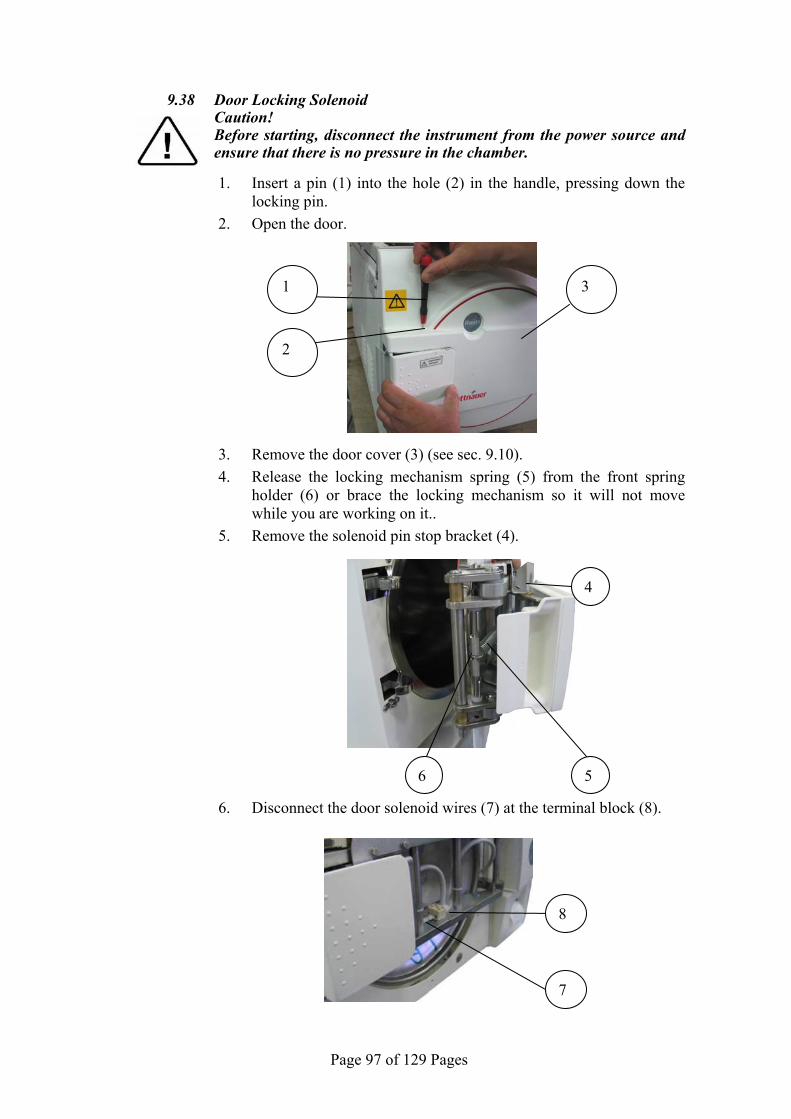
Page 97 of 129 Pages
9.38 Door Locking Solenoid Caution! Before starting, disconnect the instrument from the power source and
ensure that there is no pressure in the chamber.
1. Insert a pin (1) into the hole (2) in the handle, pressing down the locking pin.
2. Open the door.
3. Remove the door cover (3) (see sec. 9.10).
4. Release the locking mechanism spring (5) from the front spring holder (6) or brace the locking mechanism so it will not move while you are working on it..
5. Remove the solenoid pin stop bracket (4).
6. Disconnect the door solenoid wires (7) at the terminal block (8).
4
5 6
1
2
3
8
7
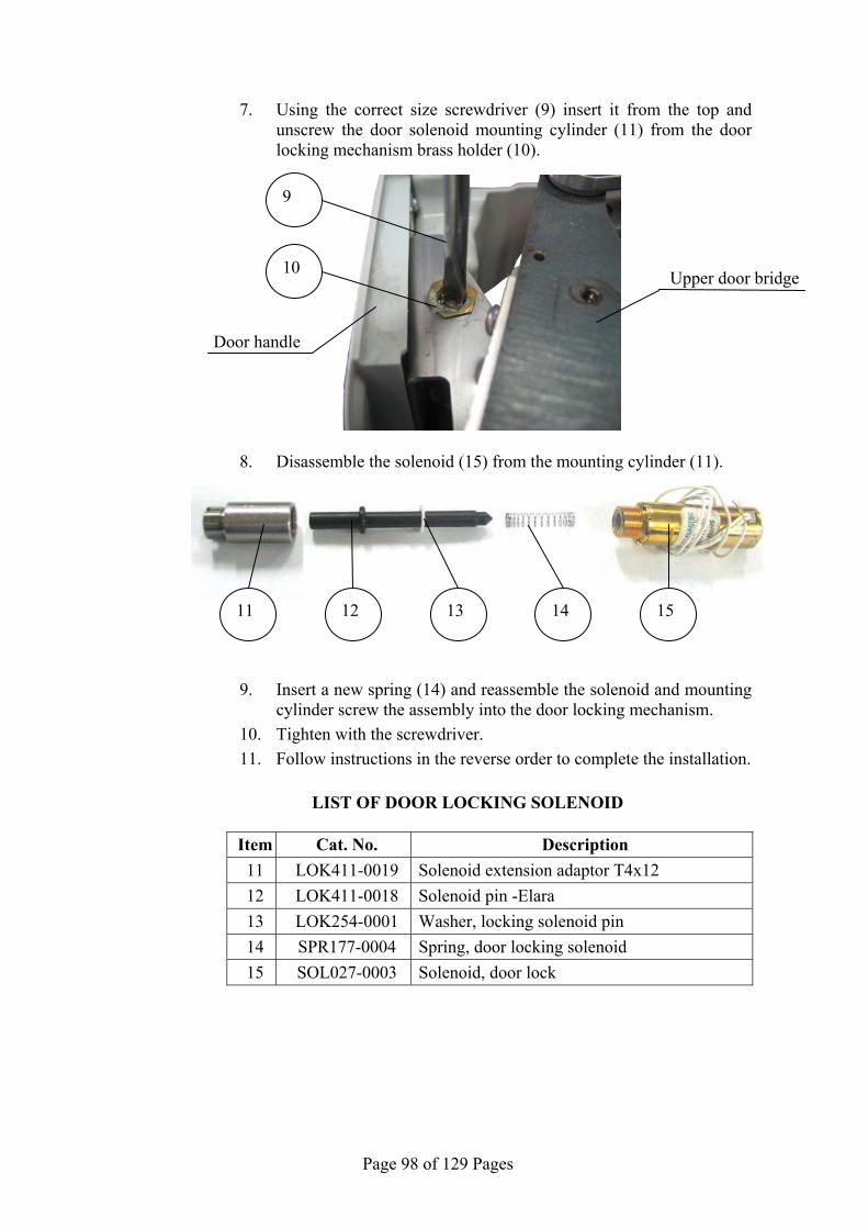
Page 98 of 129 Pages
7. Using the correct size screwdriver (9) insert it from the top and unscrew the door solenoid mounting cylinder (11) from the door locking mechanism brass holder (10).
8. Disassemble the solenoid (15) from the mounting cylinder (11).
9. Insert a new spring (14) and reassemble the solenoid and mounting cylinder screw the assembly into the door locking mechanism.
10. Tighten with the screwdriver.
11. Follow instructions in the reverse order to complete the installation.
LIST OF DOOR LOCKING SOLENOID
Item Cat. No. Description 11 LOK411-0019 Solenoid extension adaptor T4x12
12 LOK411-0018 Solenoid pin -Elara
13 LOK254-0001 Washer, locking solenoid pin
14 SPR177-0004 Spring, door locking solenoid
15 SOL027-0003 Solenoid, door lock
Upper door bridge
Door handle
9
10
12 11 13 14 15

Page 99 of 129 Pages
10 IN-OUT TEST Attention
Violating the following instructions may endanger the technician and may cause sever damage to the autoclave. Caution
Do Not operate the heating elements for an extended period of time. This can damage the heaters, the s team generator and cause possible persona l injury.” Caution
Remember to turn off all co mponents before exiting the In-Out Test o r power down and power back up to clear component ON commands.” Caution
Do Not operate the w ater pump or vacuum pump for an extended period of time. This can cause damage to the pump.
To aid in trouble shooting the autoclave the technician can perform an “In-Out
Test”. This test program allows the technician to activate and deactivate various components of the autoclave in order to evaluate that components performance. Turn on the autoclave and press the Up and DN keys simultaneously This will bring up the “Enter Code” display, with the curser under the right most digit.
1. Use the UP key to enter the code 0333.
2. Use the START/STOP key to advance the curser.
3. Advance the curser to SET and press the UP key to enter the menu page.
4. Scroll down until “In Out Test” is highlighted.
5. Press the START/STOP key to enter this submenu, which will display all the components that can be controlled.
6. To activate a component, use the UP or DN key to scroll to that component, then use the START/STOP key to activate or deactivate it.
7. To exit the “In-Out Test” scroll down to EXIT and press the START/STOP key. On the next page again scroll down to EXIT and press the START/STOP key. This will return you to the program screen.
DISPLAYED NOTICE ITEM ACTIVATED REMARKS
Air Vacuum break valve (43) Vacuum break valve is opened.
Vac Valve Vacuum valve (52) Vacuum valve is opened.
Chamb Steam Steam to chamber valve (93)
Steam to chamber valve is opened.
Warning: Do not insert any part of you body into the chamber
Fast Exh Fast exhaust valve (73) Fast exhaust valve is opened.
Dig Out #5 N/A N/A
Wtr to Res Waste water to water reservoir valve.
Applicable only if the autoclave is equipped with a waste water recycling system.
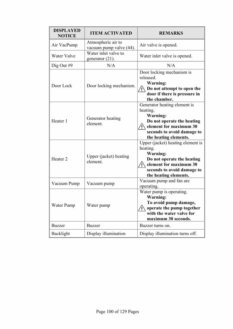
Page 100 of 129 Pages
DISPLAYED NOTICE ITEM ACTIVATED REMARKS
Air VacPump Atmospheric air to vacuum pump valve (44).
Air valve is opened.
Water Valve Water inlet valve to generator (21).
Water inlet valve is opened.
Dig Out #9 N/A N/A
Door Lock Door locking mechanism.
Door locking mechanism is released.
Warning: Do not attempt to open the door if there is pressure in the chamber.
Heater 1 Generator heating element.
Generator heating element is heating.
Warning: Do not operate the heating element for maximum 30 seconds to avoid damage to the heating elements.
Heater 2 Upper (jacket) heating element.
Upper (jacket) heating element is heating.
Warning: Do not operate the heating element for maximum 30 seconds to avoid damage to the heating elements.
Vacuum Pump Vacuum pump Vacuum pump and fan are operating.
Water Pump Water pump
Water pump is operating. Warning: To avoid pump damage, operate the pump together with the water valve for maximum 30 seconds.
Buzzer Buzzer Buzzer turns on.
Backlight Display illumination Display illumination turns off.

Page 101 of 129 Pages
11 TROUBLESHOOTING NOTE Cleaning and maintenance are the responsibility of the user”
11.1 Preliminary Check
NOTE! Most of the autoclave's malfunctions result from dirt. Before performing troubleshooting at the customer location we
recommend to follow the procedure described bellow: o Disconnect the autoclave from the electric power source. o Remove the covers. o Clean the trays and the trays holder. o Clean the filters. o Remove the plungers of the solenoid and clean the solenoid base.
Replace plungers if required. o Inspect that there are no sign of water leaks or sediments. o Inspect and make sure that there are no sign of electric loose
connections. o Tighten all the loose screws, nuts and piping connections.

Page 102 of 129 Pages
11.2 Troubleshooting procedure
Symptom Possible cause check-up and tests Corrections
No light in the display
Main switch is off. Turn main switch on.
The electrical power or the connections at the autoclave input are faulty.
Make sure that there is power source according to the utilities.Make sure that the power cord is not damaged and that it is connected well. If the safety circuit breaker shuts off the power make sure that there are no sign of water. Make sure that there are no un-isolated wires.
The steam generator Cut-off thermostat tripped.
Reset cut-off thermostat. If problem persists, clean or replace the generator's water level electrode.
The steam generator Cut-off thermostat is faulty.
Replace the faulty cut-off thermostat.
One of the fuses of the transformer are burnt.
Replace the burnt fuse.
Transformer is faulty. Replace the transformer.
Main switch is faulty. Replace the main switch.
Electrical wiring loose or making short-circuit.
Find the loosing wire or connector.
Symptom Possible cause check-up and tests Corrections
Err:001 is displayed
PT1 out
PT100 No. 1 of the chamber is disconnected.
Reconnect the PT100.
PT100 of the chamber is faulty (JP1).
Test the sensor circuit according to sec 9.34.
Nova4-D2 board is faulty. Replace the faulty Nova4-A2.
Symptom Possible cause check-up and tests Corrections
Err:002 is displayed
Low Temperature
Heating elements do not heat.
Heating element wire disconnected
Reconnect wires to the heating elements.
Faulty heating elements.
Unplug the unit then disconnect the generator heating element wires from the terminal block. Take an ohm reading on the heating element - 23 ohms. Replace faulty heating elements as needed.
Check piping for blockage. Check water pump. Check watersolenoid valve. Check for faulty check valve.

Page 103 of 129 Pages
Symptom Possible cause check-up and tests Corrections
Err:002 is displayed (cont.)
Low Temperature (cont.)
Generator's water level electrode has a scale build up.
Clean or replace the generator's water electrode.
Chamber’s temperature sensor is:
Not calibrated. Calibrate the sensor.
Faulty. Test the sensor circuit according to sec 9.34.
Dirt or sediments in the steam generator.
Take out the steam generator clean the sediments.
A solenoid valve is leaking - Fast Exhaust (73), Vacuum valve (52) or Air (43).
Take apart, clean and inspect seats - replace if worn or damaged
Door gasket is leaking Clean with mild soapy water - replace if worn or damaged
Sterilization time set to long Reduce Sterilization time
Generator cut-off faulty turning off the heat prematurely
Replace cut-off if faulty - do not attempt to adjust
Steam valve (93) is faulty restricting the steam to chamber
Check for magnetism at the coil. With coil disconnected read ~7 ohms across coil. Read 0 ohms between the coil terminal and the ground terminal. Replace thefaulty coil
Steam valve (93) control circuit faulty
Check for proper voltage to the machine (230 VAC). Insert test leads into JP13 pins 1 and 5. A properly working solenoid will show ~0 VAC when off, ~18 VAC when on. With test lead in JP 13 pin 1 and 5 and the coil disconnected there should be ~18 VAC across the pins with the valve turned on or off. Replace a faulty circuit board. With the coil disconnected there should be ~18 VAC on connection box terminals with the valve turned on or off. Repair broken wire.
Safety valve leaking Replace the safety valve
Symptom Possible cause check-up and tests Corrections
Err:003 is displayed
High Temperature
Chamber’s temperature sensor is not calibrated.
Calibrate the sensor.
Chamber’s temperature sensor is faulty.
Test the sensor circuit according to sec 9.34.

Page 104 of 129 Pages
Symptom Possible cause check-up and tests Corrections
Err:005 is displayed
High Gen Press
Generator’s pressure sensor is not calibrated.
Calibrate the sensor.
Generator's pressure sensor is faulty
Test the sensor circuit according to sec 9.37.
The heater in the generator does not stop heating as a result of a problem:
In the pressure switch.
With the generator at or above the target pressure disconnect the wire of the pressure switch. If the heater turns off the switch is faulty. Replace the faulty switch.
In the AC high voltage power board (Nova4-A2) board.
Replace the faulty Nova4-A2.
Symptom Possible cause check-up and tests Corrections
Err:007 is displayed
High pressure
Steam to chamber valve (93) does not close as a result of adirty or faulty plunger.
Take apart, clean and inspect seats - replace if worn or damaged.
Chamber’s pressure sensor is not calibrated.
Open the autoclave’s door and read chamber pressure on the display if reading is not accuratethan check that the atmospheric pressure parameter is set correctly, calibrate the chamber’s pressure sensor if needed.
Chamber’s pressure sensor is faulty.
Test the sensor circuit according to sec 9.36.
Symptom Possible cause check-up and tests Corrections
Err:008 is displayed
Low Pressure
Door seal is dirty or faulty. Clean or replace door seal.
Piping is leaking. Fix the leaking point.
Air valve (43) is leaking. Take apart, clean and inspect seats - replace if worn or damaged.
Exhaust valve (73) is leaking. Take apart, clean and inspect seats - replace if worn or damaged.
Vacuum valve (52) is leaking. Take apart, clean and inspect seats - replace if worn or damaged.
Steam valve (93) is leaking. Take apart, clean and inspect seats - replace if worn or damaged.

Page 105 of 129 Pages
Symptom Possible cause check-up and tests Corrections
Safety valve is leaking. Close Pressure Relief Nut or replace the valve.
Chamber’s pressure sensor is not calibrated.
Open the autoclave's door and read the chamber pressure on the display If the reading is not accurate then check that the atmospheric pressure parameter is set correctly. Calibrate the chamber's pressure sensor if needed.
Chamber’s pressure sensor is faulty.
Test the sensor circuit according to sec 9.36.
Steam valve (93) is faulty restricting the steam to chamber
Check for magnetism at the coil. With coil disconnected read ~7 ohms across coil. Read 0 ohms between the coil terminal and the ground terminal. Replace the faulty coil.
Steam valve (93) control circuit faulty
Check for proper voltage to the machine (230 VAC). Insert test leads into JP13 pins 1 and 5. A properly working solenoid will show ~0 VAC when off, ~18 VAC when on. With test lead in JP 13 pin 1 and 5 and the coil disconnected there should be ~18 VAC across the pins with the valve turned on or off. Replace a faulty circuit board. With the coil disconnected there should be ~18 VAC on connection box terminals with the valve turned on or off. Repair broken wire.
Generator’s pressure sensor is not calibrated.
Calibrate the sensor.
Generator’s pressure sensor is faulty.
Test the sensor circuit according to sec 9.37.
Symptom Possible cause check-up and tests Corrections
Err:009 is displayed
System Error This message displayed if the real time clock is faulty.
Replace the Nova4-D2 board.

Page 106 of 129 Pages
Symptom Possible cause check-up and tests Corrections
Err:011 is displayed Door is
Open
The error is displayed despite that the door is closed. The door switch is faulty.
Replace the door switch.
The error is displayed despite that the door is closed. The door switch is out of adjustment.
Remove the two screws holding the door switch mounting block to the front panel. Adjust the door switch (see sec. 9.16)..
The error is displayed despite that the door is closed. The door is not fully closed.
Close the door with more force.
The error is displayed despite that the door is closed. The control wire from the door switch is not connected.
Repair the broken control wire
Symptom Possible causecheck-up and tests Corrections
Err:012 is displayed
Manual Stop
The START/STOP key was pressed and the cycle is aborted.
Press the START/STOP key to delete the error message. To openthe door, wait until the pressure decreases to ambient pressure.
Symptom Possible causecheck-up and tests Corrections
Err:013 is displayed
Air Valve (43) Error
Air filter is clogged. Replace the air filter. Air inlet tube is clogged or kinked. Clear the air inlet tube.
Air valve (43) plunger is clogged.
Take apart, clean and inspect seats. Replace if worn or damaged.
Air valve (43) coil is faulty Check for magnetism at the coil. With coil disconnected read ~7 ohms across coil. Read 0 ohms between the coil terminal and the ground terminal. Replace the faulty coil
Air valve (43) control circuit is faulty
Check for proper voltage to the machine (230 VAC). Insert test leads into JP13 pins 1 and 3. A properly working solenoid will show ~0 VAC when off, ~18 VAC when on. With test lead in JP 13 pin 1 and 3 and the coil disconnected there should be ~18 VAC across the pins with the valve turned on or off. Replace a faulty circuit board. With the coil disconnected there should be ~18 VAC on connection box terminals with the valve turned on or off. Repair broken wire.

Page 107 of 129 Pages
Symptom Possible causecheck-up and tests Corrections
Err:014 is displayed
Low Vacuum
Vac
uum
pum
p ru
ns b
ut n
o va
cuum
is p
rodu
ced
due
to:
Door is not fully closed Close the door with more force.
Door seal is dirty or faulty. Clean or replace the door seal.
Piping is leaking. Fix the leak. A valve is leaking - Fast Exhaust (73), Air to Vac (44), Air (43) or Steam to Chamber (93).
Take apart, clean and inspect seats - replace if worn or damaged
Vacuum valve (52) coil is faulty
Check for magnetism at the coil. With coil disconnected read ~7 ohms across coil. Read 0 ohms between the coil terminal and the ground terminal. Replace the faulty coil,
Vacuum valve (52) control circuit is faulty
Check for proper voltage to the machine (230 VAC). Insert test leads into JP13 pins 1 and 4. A properly working solenoid will show ~0 VAC when off, ~18 VAC when on. With test lead in JP 13 pin 1 and 4 and the coil disconnected there should be ~18 VAC across the pins with the valve turned on or off. Replace a faulty circuit board. With the coil disconnected there should be ~18 VAC on connection box terminals with the valve turned on or off. Repair broken wire.
Air to vacuum valve (44) coil is faulty.
Check for magnetism at the coil. With coil disconnected read ~7 ohms across coil. Read 0 ohms between the coil terminal and the ground terminal. Replace the faulty coil.
Air to vacuum valve (44) control circuit is faulty
Check for proper voltage to the machine (230 VAC). Insert test leads into JP13 pins 1 and 9. A properly working solenoid will show ~0 VAC when off, ~18 VAC when on. With test lead in JP 13 pin 1 and 9 and the coil disconnected there should be ~18 VAC across the pins with the valve turned on or off. Replace a faulty circuit board. With the coil disconnected there should be ~18 VAC on connection box terminals with the valve turned on or off. Repair broken wire.

Page 108 of 129 Pages
Symptom Possible causecheck-up and tests Corrections
Cooler is blocked.
1. Ensure there is a minimum 2" clearance at the back of the unit. Inside a cabinet the rear cabinet panel needs to be removed.
2. Blow air through the fins of the radiator to remove dust and dirt that may be restricting air flow.
Cooler is leaking.
Disconnect the inlet and outlet tube and run water through the piping to check for a blockage. Pressure test with water and check for leaks. Replace cooler.
Cooler fan is faulty. Clean fan blades of dirt build up. Replace fan.
Pump need to be rebuilt. Install rebuilding kit.
Vac
uum
pum
p do
es n
ot
oper
ate
due
to:
Pump's fuse burnt Replace fuse on the Nova4-A2 board.
Disconnected wire. Reconnect wires.
Faulty vacuum pump Replace the faulty vacuum pump.
AC high voltage power board (Nova4-A2) board is faulty.
Replace the Nova4-A2 board.
Symptom Possible cause check-up and tests Corrections
Err:015 is displayed
Low Heat
Generator's heating element is disconnected or burnt.
Unplug the unit then disconnect the generator heating element wires from the terminal block. Take an ohm reading on the heating element - 23 ohms. Reconnect or replace the heating element as needed.
Chamber's heating element is disconnected or burnt.
Unplug the unit then trace the chamber heating element wires to the two plug in connectors then disconnect the heating element wires. Take an ohm reading on the chamber heating element - 105 ohms. Reconnect or replace the heating element as needed.

Page 109 of 129 Pages
Symptom Possible cause check-up and tests Corrections
Generator’s water level electrode has a scale build up.
Clean or replace the generator’s water electrode.
Insu
ffic
ient
or
no w
ater
sup
ply
to th
e ge
nera
tor.
Piping to and from water pump is clogged.
Clean water pump filter. Unclog piping.
Water valve (21) is clogged
Take apart, clean and inspect seats - replace if worn or damaged.
Water valve (21) is faulty.
Check for magnetism at the coil. With coil disconnected read ~7 ohms across coil. Read 0 ohms between the coil terminal and the ground terminal. Replace the faulty coil.
Water valve (21) control circuit is faulty.
Check for proper voltage to the machine (230 VAC). Insert test leads into JP13 pins 1 and 10. A properly working solenoid will show ~0 VAC when off, ~18 VAC when on. With test lead in JP 13 pin 1 and 10 and the coil disconnected there should be ~18 VAC across the pins with the valve turned on or off. Replace a faulty circuit board. With the coil disconnected there should be ~18 VAC on connection box terminals with the valve turned on or off. Repair broken wire.
Water pump fuse is burnt.Replace fuse on the Nova4-A2 board.
Faulty water pump. Replace water pump
Water pump does not run - AC high voltage power board is faulty.
Replace the Nova4-A2 board.
Water check valve is faulty.
Replace check valve.

Page 110 of 129 Pages
Symptom Possible cause check-up and tests Corrections
Err:016 is displayed Press Sensor
Cutout
Chamber’s pressure sensor is:
Disconnected Reconnect the chamber’s pressure sensor.
Faulty Test the sensor circuit according to sec 9.36.
Faulty Nova4-D2 board Replace faulty board.
Symptom Possible cause check-up and tests Corrections
Err:017 is displayed
Pt2 out
Chamber's wall temperature sensor (JP3) is:
Disconnected Reconnect the chamber's wall PT100.
Faulty Test the sensor circuit according to sec 9.35.
Faulty Nova4-D2 board Replace faulty board.
Symptom Possible cause check-up and tests Corrections
Err:018
Press Sensor Cutout
Generator’s pressure sensor is
Disconnected Reconnect the chamber's wall PT100.
Faulty Test the sensor circuit according to sec 9.37.
Faulty Nova4-D2 board Replace faulty board.
Symptom Possible cause check-up and tests Corrections
Err:020 is displayed
No Gen water
Insufficient or no water supply to the generator. Piping to and from water pump is clogged.
Clean water pump filter. Unclog piping.
Water pump is faulty. Check water pump fuse. Check water pump is receiving power. Replace water pump.
Generator's water level electrode has a scale build up.
Clean or replace the generator’s water level electrode.
Water sensor wire is disconnected.
Reconnect sensor wire.
insufficient or no water supply to the generator. Water valve plunger (21) is clogged.
Take apart, clean and inspect seats - replace if worn or damaged
insufficient or no water supply to the generator. Water valve coil (21) is faulty
Check for magnetism at the coil. With coil disconnected read ~7 ohms across coil. Read 0 ohms between the coil terminal and the ground terminal. Replace thefaulty coil

Page 111 of 129 Pages
Symptom Possible cause check-up and tests Corrections
insufficient or no water supply to the generator. Water valve (21) control circuit is faulty
Check for proper voltage to the machine (230 VAC). Insert test leads into JP13 pins 1 and 10. Aproperly working solenoid will show ~0 VAC when off, ~18 VAC when on. With test lead in JP 13 pin 1 and 10 and the coil disconnected there should be ~18 VAC across the pins with the valve turned on or off. Replace a faulty circuit board. With the coil disconnected there should be ~18 VAC on connection box terminals with the valve turned on or off. Repair broken wire.
insufficient or no water supply to the generator. Water check valve is faulty
Replace check valve
Symptom Possible cause check-up and tests Corrections
Err:021 is displayed
Vacuum Test Fail
Door seal is dirty or faulty. Clean or replace the door seal.
Piping is leaking. Fix the leaking point.
Symptom Possible cause check-up and tests Corrections
This symbol is displayed
No water
Mineral free water reservoir is empty.
Pour mineral-free water in the front funnel until it reaches the "full" level.
The symbol appears despite that the reservoir is full: water level electrodes are disconnected, dirty or faulty.
Fix, clean or replace water level electrodes in the mineral-free water reservoir.
Symptom Possible cause check-up and tests Corrections
Mineral free water reservoir is empty but "no water" symbol does not appear.
The two water level electrodes may be connected with dirt,
Clean water level electrodes in the mineral-free water reservoir.
The water level electrodes may be short-circuited.
Locate and Fix the short circuit.

Page 112 of 129 Pages
Symptom Possible cause check-up and tests Corrections
This symbol is displayed
Remove water
The waste water reservoir is full.
Empty the waste water reservoir.
The symbol appears despite that the reservoir is empty: water level electrodes are dirty, disconnected or faulty.
Fix, clean or replace water level electrodes of the waste water reservoir.
Symptom Possible cause check-up and tests Corrections
This symbol is displayed
Low Chamber wall Temp
The autoclave is preheating (not ready).
Wait for the autoclave to reach the proper operating conditions for starting a new cycle.
Heating element wire disconnected.
reconnect wire to the heating elements
Faulty heating elements Unplug the unit then trace the chamber heating element wires to the two plug in connectors then disconnect the heating element wires. Take an ohm reading on the chamber heating element - 105 ohms. Reconnect or replace heating elements as needed
Chamber's wall temperature sensor is:
Disconnected(JP3)
Reconnect the chamber's wall PT100.
Not calibratedCalibrate the chamber's wall PT100.
Faulty Test the sensor circuit according to sec 9.35.
Symptom Possible cause check-up and tests Corrections
Door does not open
The autoclave is not powered. Turn-on the autoclave.
The locking solenoid is disconnected.
See emergency opening sec 938. Check connection block behind door cover. Check connection on Nova4-D2 board.
The locking solenoid is faulty. Replace the locking solenoid.
Symptom Possible cause check-up and tests Corrections
Operational screen does not appear
"Loading" message is displayed for more than 10 seconds
The software program is corrupted. Replace the Nova4-D2 board
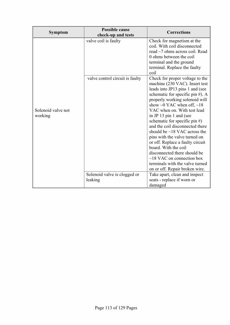
Page 113 of 129 Pages
Symptom Possible cause check-up and tests Corrections
Solenoid valve not working
valve coil is faulty Check for magnetism at the coil. With coil disconnected read ~7 ohms across coil. Read 0 ohms between the coil terminal and the ground terminal. Replace the faulty coil
valve control circuit is faulty Check for proper voltage to the machine (230 VAC). Insert test leads into JP13 pins 1 and (see schematic for specific pin #). A properly working solenoid will show ~0 VAC when off, ~18 VAC when on. With test lead in JP 13 pin 1 and (see schematic for specific pin #) and the coil disconnected there should be ~18 VAC across the pins with the valve turned on or off. Replace a faulty circuit board. With the coil disconnected there should be ~18 VAC on connection box terminals with the valve turned on or off. Repair broken wire.
Solenoid valve is clogged or leaking
Take apart, clean and inspect seats - replace if worn or damaged

Page 114 of 129 Pages
12 PRESSURE VS TEMPERATURE FOR SATURATED STEAM °C kPa Bar °F psig psia°C kPa Bar °F InHg psia
104.3 117.9 1.18 219.7 2.4 17.1 45.8 10 0.10 114.5 2.95 1.5 104.4 118.6 1.18 219.9 2.5 17.2 54.1 15 0.15 129.3 4.44 2.2 104.5 118.6 1.19 220.1 2.5 17.2 60.1 20 0.20 140.2 5.90 2.9 104.6 119.3 1.19 220.3 2.6 17.3 65.0 25 0.25 149.1 7.39 3.6 104.7 120.0 1.20 220.5 2.7 17.4 68.9 30 0.30 156.4 8.86 4.4 104.8 120.0 1.20 220.6 2.7 17.4 72.7 35 0.35 162.9 10.34 5.1 104.9 120.4 1.20 220.8 2.8 17.5 75.9 40 0.40 168.6 11.81 5.8 105.0 120.7 1.21 221.0 2.8 17.5 78.8 45 0.45 173.8 13.30 6.5 105.1 121.3 1.21 221.2 2.9 17.6 81.3 50 0.50 178.4 14.76 7.3 105.2 122.0 1.22 221.4 3.0 17.7 105.3 122.0 1.22 221.5 3.0 17.7 °C kPa Bar °F psig psia 105.4 122.7 1.23 221.7 3.1 17.8 100.0 101.3 1.01 212.0 0.0 14.7 105.5 122.7 1.23 221.9 3.1 17.8 100.1 101.7 1.02 212.2 0.1 14.8 105.6 123.4 1.23 222.1 3.2 17.9 100.2 102.1 1.02 212.4 0.1 14.8 105.7 124.1 1.24 222.3 3.3 18.0 100.3 102.4 1.02 212.5 0.2 14.9 105.8 124.1 1.24 222.4 3.3 18.0 100.4 102.8 1.03 212.7 0.2 14.9 105.9 124.7 1.24 222.6 3.4 18.1 100.5 103.2 1.03 212.9 0.3 15.0 106.0 125.1 1.25 222.8 3.5 18.2 100.6 103.6 1.04 213.1 0.3 15.0 106.1 125.5 1.26 223.0 3.5 18.2 100.7 104.0 1.04 213.3 0.4 15.1 106.2 126.0 1.26 223.2 3.6 18.3 100.8 104.3 1.04 213.4 0.4 15.1 106.3 126.2 1.26 223.3 3.6 18.3 100.9 104.7 1.05 213.6 0.5 15.2 106.4 126.8 1.27 223.5 3.7 18.4 101.0 105.1 1.05 213.8 0.5 15.2 106.5 127.2 1.27 223.7 3.8 18.5 101.1 105.4 1.05 214.0 0.6 15.3 106.6 127.7 1.28 223.9 3.8 18.5 101.2 105.8 1.06 214.2 0.7 15.4 106.7 128.1 1.28 224.1 3.9 18.6 101.3 106.2 1.06 214.3 0.7 15.4 106.8 128.5 1.29 224.2 3.9 18.6 101.4 106.6 1.07 214.5 0.8 15.5 106.9 129.0 1.29 224.4 4.0 18.7 101.5 106.9 1.07 214.7 0.8 15.5 107.0 129.6 1.29 224.6 4.1 18.8 101.6 107.3 1.07 214.9 0.9 15.6 107.1 129.9 1.30 224.8 4.2 18.9 101.7 107.7 1.08 215.1 0.9 15.6 107.2 130.4 1.30 225.0 4.2 18.9 101.8 108.1 1.08 215.2 1.0 15.7 107.3 130.8 1.31 225.1 4.3 19.0 101.9 108.4 1.08 215.4 1.0 15.7 107.4 131.3 1.31 225.3 4.3 19.0 102.0 108.8 1.09 215.6 1.1 15.8 107.5 131.7 1.32 225.5 4.4 19.1 102.1 109.2 1.09 215.8 1.1 15.8 107.6 132.2 1.32 225.7 4.5 19.2 102.2 109.6 1.10 216.0 1.2 15.9 107.7 132.6 1.33 225.9 4.6 19.3 102.4 110.0 1.10 216.3 1.3 16.0 107.8 133.1 1.33 226.0 4.6 19.3 102.5 110.7 1.11 216.5 1.4 16.1 107.9 133.5 1.34 226.2 4.7 19.4 102.6 111.1 1.11 216.7 1.4 16.1 108.0 134.0 1.34 226.4 4.7 19.4 102.7 111.5 1.12 216.9 1.5 16.2 108.1 134.4 1.34 226.6 4.8 19.5 102.8 111.9 1.12 217.0 1.5 16.2 108.2 134.9 1.35 226.8 4.9 19.6 102.9 112.3 1.12 217.2 1.6 16.3 108.3 135.3 1.35 226.9 4.9 19.6 103.0 112.7 1.13 217.4 1.7 16.4 108.4 135.8 1.36 227.1 5.0 19.7 103.1 113.1 1.13 217.6 1.7 16.4 108.5 136.2 1.36 227.3 5.1 19.8 103.2 113.5 1.14 217.8 1.8 16.5 108.6 136.7 1.37 227.5 5.1 19.8 103.3 114.0 1.14 217.9 1.8 16.5 108.7 137.1 1.37 227.7 5.2 19.9 103.4 114.3 1.14 218.1 1.9 16.6 108.8 137.6 1.38 227.8 5.2 19.9 103.5 114.7 1.15 218.3 1.9 16.6 108.9 138.1 1.38 228.0 5.3 20.0 103.6 115.1 1.15 218.5 2.0 16.7 109.0 138.5 1.39 228.2 5.4 20.1 103.7 115.6 1.16 218.7 2.1 16.8 109.1 139.0 1.39 228.4 5.5 20.2 103.8 116.0 1.16 218.8 2.1 16.8 109.2 139.5 1.39 228.6 5.6 20.3 103.9 116.3 1.16 219.0 2.2 16.9 109.3 140.0 1.40 228.7 5.6 20.3 104.0 116.7 1.17 219.2 2.2 16.9 109.4 140.5 1.40 228.9 5.7 20.4 104.1 117.1 1.17 219.4 2.3 17.0 109.5 140.9 1.41 229.1 5.7 20.4 104.2 117.5 1.18 219.6 2.4 17.1
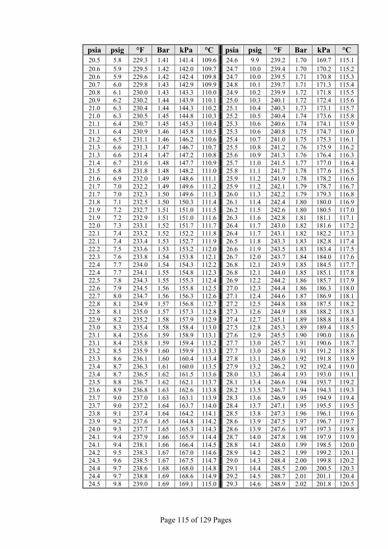
Page 115 of 129 Pages
°C kPa Bar °F psig psia°C kPa Bar °F psig psia 115.1 169.7 1.70 239.2 9.9 24.6 109.6 141.4 1.41 229.3 5.8 20.5 115.2 170.2 1.70 239.4 10.0 24.7 109.7 142.0 1.42 229.5 5.9 20.6 115.3 170.8 1.71 239.5 10.0 24.7 109.8 142.4 1.42 229.6 5.9 20.6 115.4 171.3 1.71 239.7 10.1 24.8 109.9 142.9 1.43 229.8 6.0 20.7 115.5 171.8 1.72 239.9 10.2 24.9 110.0 143.3 1.43 230.0 6.1 20.8 115.6 172.4 1.72 240.1 10.3 25.0 110.1 143.9 1.44 230.2 6.2 20.9 115.7 173.1 1.73 240.3 10.4 25.1 110.2 144.3 1.44 230.4 6.3 21.0 115.8 173.6 1.74 240.4 10.5 25.2 110.3 144.8 1.45 230.5 6.3 21.0 115.9 174.1 1.74 240.6 10.6 25.3 110.4 145.3 1.45 230.7 6.4 21.1 116.0 174.7 1.75 240.8 10.6 25.3 110.5 145.8 1.46 230.9 6.4 21.1 116.1 175.3 1.75 241.0 10.7 25.4 110.6 146.2 1.46 231.1 6.5 21.2 116.2 175.9 1.76 241.2 10.8 25.5 110.7 146.7 1.47 231.3 6.6 21.3 116.3 176.4 1.76 241.3 10.9 25.6 110.8 147.2 1.47 231.4 6.6 21.3 116.4 177.0 1.77 241.5 11.0 25.7 110.9 147.7 1.48 231.6 6.7 21.4 116.5 177.6 1.78 241.7 11.1 25.8 111.0 148.2 1.48 231.8 6.8 21.5 116.6 178.2 1.78 241.9 11.2 25.9 111.1 148.6 1.49 232.0 6.9 21.6 116.7 178.7 1.79 242.1 11.2 25.9 111.2 149.6 1.49 232.2 7.0 21.7 116.8 179.3 1.79 242.2 11.3 26.0 111.3 149.6 1.50 232.3 7.0 21.7 116.9 180.0 1.80 242.4 11.4 26.1 111.4 150.3 1.50 232.5 7.1 21.8 117.0 180.5 1.80 242.6 11.5 26.2 111.5 151.0 1.51 232.7 7.2 21.9 117.1 181.1 1.81 242.8 11.6 26.3 111.6 151.0 1.51 232.9 7.2 21.9 117.2 181.6 1.82 243.0 11.7 26.4 111.7 151.7 1.52 233.1 7.3 22.0 117.3 182.2 1.82 243.1 11.7 26.4 111.8 152.2 1.52 233.2 7.4 22.1 117.4 182.8 1.83 243.3 11.8 26.5 111.9 152.7 1.53 233.4 7.4 22.1 117.5 183.4 1.83 243.5 11.9 26.6 112.0 153.2 1.53 233.6 7.5 22.2 117.6 184.0 1.84 243.7 12.0 26.7 112.1 153.8 1.54 233.8 7.6 22.3 117.7 184.5 1.85 243.9 12.1 26.8 112.2 154.3 1.54 234.0 7.7 22.4 117.8 185.1 1.85 244.0 12.1 26.8 112.3 154.8 1.55 234.1 7.7 22.4 117.9 185.7 1.86 244.2 12.2 26.9 112.4 155.3 1.55 234.3 7.8 22.5 118.0 186.3 1.86 244.4 12.3 27.0 112.5 155.8 1.56 234.5 7.9 22.6 118.1 186.9 1.87 244.6 12.4 27.1 112.6 156.3 1.56 234.7 8.0 22.7 118.2 187.5 1.88 244.8 12.5 27.2 112.7 156.8 1.57 234.9 8.1 22.8 118.3 188.2 1.88 244.9 12.6 27.3 112.8 157.3 1.57 235.0 8.1 22.8 118.4 188.8 1.89 245.1 12.7 27.4 112.9 157.9 1.58 235.2 8.2 22.9 118.5 189.4 1.89 245.3 12.8 27.5 113.0 158.4 1.58 235.4 8.3 23.0 118.6 190.0 1.90 245.5 12.9 27.6 113.1 158.9 1.59 235.6 8.4 23.1 118.7 190.6 1.91 245.7 13.0 27.7 113.2 159.4 1.59 235.8 8.4 23.1 118.8 191.2 1.91 245.8 13.0 27.7 113.3 159.9 1.60 235.9 8.5 23.2 118.9 191.8 1.92 246.0 13.1 27.8 113.4 160.4 1.60 236.1 8.6 23.3 119.0 192.4 1.92 246.2 13.2 27.9 113.5 160.0 1.61 236.3 8.7 23.4 119.1 193.0 1.93 246.4 13.3 28.0 113.6 161.5 1.62 236.5 8.7 23.4 119.2 193.7 1.94 246.6 13.4 28.1 113.7 162.1 1.62 236.7 8.8 23.5 119.3 194.3 1.94 246.7 13.5 28.2 113.8 162.6 1.63 236.8 8.9 23.6 119.4 194.9 1.95 246.9 13.6 28.3 113.9 163.1 1.63 237.0 9.0 23.7 119.5 195.5 1.95 247.1 13.7 28.4 114.0 163.7 1.64 237.2 9.0 23.7 119.6 196.1 1.96 247.3 13.8 28.5 114.1 164.2 1.64 237.4 9.1 23.8 119.7 196.7 1.97 247.5 13.9 28.6 114.2 164.8 1.65 237.6 9.2 23.9 119.8 197.3 1.97 247.6 13.9 28.6 114.3 165.3 1.65 237.7 9.3 24.0 119.9 197.9 1.98 247.8 14.0 28.7 114.4 165.9 1.66 237.9 9.4 24.1 120.0 198.5 1.99 248.0 14.1 28.8 114.5 166.4 1.66 238.1 9.4 24.1 120.1 199.2 1.99 248.2 14.2 28.9 114.6 167.0 1.67 238.3 9.5 24.2 120.2 199.8 2.00 248.4 14.3 29.0 114.7 167.5 1.67 238.5 9.6 24.3 120.3 200.5 2.00 248.5 14.4 29.1 114.8 168.0 1.68 238.6 9.7 24.4 120.4 201.1 2.01 248.7 14.5 29.2 114.9 168.6 1.69 238.8 9.7 24.4 120.5 201.8 2.02 248.9 14.6 29.3 115.0 169.1 1.69 239.0 9.8 24.5

Page 116 of 129 Pages
°C kPa Bar °F psig psia°C kPa Bar °F psig psia 125.9 238.7 2.39 258.6 19.9 34.6 120.6 202.4 2.02 249.1 14.7 29.4 126.0 239.4 2.39 258.8 20.0 34.7 120.7 203.1 2.03 249.3 14.8 29.5 126.1 240.2 2.40 259.0 20.1 34.8 120.8 203.7 2.04 249.4 14.8 29.5 126.2 240.9 2.41 259.2 20.2 34.9 120.9 204.4 2.04 249.6 14.9 29.6 126.3 241.6 2.42 259.3 20.3 35.0 121.0 205.0 2.05 249.8 15.0 29.7 126.4 242.3 2.42 259.5 20.4 35.1 121.1 205.7 2.06 250.0 15.3 29.8 126.5 243.1 2.43 259.7 20.6 35.3 121.2 206.3 2.06 250.2 15.4 29.9 126.6 243.8 2.44 259.9 20.7 35.4 121.3 207.0 2.07 250.3 15.5 30.0 126.7 244.5 2.45 260.1 20.8 35.5 121.4 207.6 2.08 250.5 15.6 30.1 126.8 245.3 2.45 260.2 20.9 35.6 121.5 208.3 2.08 250.7 15.6 30.3 126.9 246.0 2.46 260.4 21.0 35.7 121.6 208.9 2.09 250.9 15.8 30.5 127.0 246.8 2.47 260.6 21.1 35.8 121.7 209.6 2.10 251.1 15.8 30.5 127.1 247.6 2.48 260.8 21.2 35.9 121.8 210.2 2.10 251.2 15.9 30.6 127.2 248.3 2.48 261.0 21.3 36.0 121.9 210.8 2.11 251.4 16.0 30.7 127.3 249.1 2.49 261.1 21.4 36.1 122.0 211.5 2.11 251.6 16.1 30.8 127.4 249.9 2.50 261.3 21.5 36.2 122.1 212.1 2.12 251.8 16.3 31.0 127.5 250.6 2.51 261.5 21.8 36.5 122.2 212.8 2.13 252.0 16.3 31.0 127.6 251.4 2.51 261.7 21.8 36.5 122.3 213.5 2.13 252.1 16.4 31.1 127.7 252.2 2.52 261.9 21.9 36.6 122.4 214.2 2.14 252.3 16.5 31.2 127.8 252.9 2.53 262.0 22.0 36.7 122.5 214.8 2.15 252.5 16.6 31.3 127.9 253.7 2.54 262.2 22.1 36.8 122.6 215.2 2.16 252.7 16.7 31.4 128.0 254.5 2.54 262.4 22.2 36.9 122.7 216.2 2.16 252.9 16.8 31.5 128.1 255.2 2.55 262.6 22.3 37.0 122.8 216.9 2.17 253.0 16.9 31.6 128.2 256.0 2.56 262.8 22.4 37.1 122.9 217.6 2.18 253.2 17.0 31.7 128.3 256.8 2.57 262.9 22.5 37.2 123.0 218.3 2.18 253.4 17.1 31.8 128.4 257.5 2.58 263.1 22.7 37.4 123.1 218.9 2.19 253.6 17.1 31.8 128.5 258.3 2.58 263.3 22.8 37.5 123.2 219.6 2.20 253.8 17.2 31.9 128.6 259.1 2.59 263.5 22.9 37.6 123.3 220.3 2.20 253.9 17.3 32.0 128.7 259.8 2.60 263.7 23.0 37.7 123.4 221.0 2.21 254.1 17.4 32.1 128.8 260.6 2.61 263.8 23.1 37.8 123.5 221.7 2.22 254.3 17.5 32.2 128.9 261.4 2.61 264.0 23.2 37.9 123.6 222.4 2.22 254.5 17.6 32.3 129.0 262.2 2.62 264.2 23.3 38.0 123.7 223.1 2.23 254.7 17.7 32.4 129.1 263.0 2.63 264.4 23.4 38.1 123.8 223.7 2.24 254.8 17.8 32.5 129.2 263.8 2.64 264.6 23.6 38.3 123.9 224.4 2.24 255.0 17.9 32.6 129.3 264.6 2.65 264.7 23.7 38.4 124.0 225.1 2.25 255.2 17.9 32.6 129.4 265.4 2.65 264.9 23.8 38.5 124.1 225.8 2.26 255.4 18.0 32.7 129.5 266.2 2.66 265.1 23.9 38.6 124.2 226.5 2.26 255.6 18.1 32.8 129.6 267.0 2.67 265.3 24.0 38.7 124.3 227.2 2.27 255.7 18.2 32.9 129.7 267.8 2.68 265.5 24.1 38.8 124.4 227.9 2.28 255.9 18.3 33.0 129.8 268.6 2.69 265.6 24.3 39.0 124.5 228.6 2.29 256.1 18.4 33.1 129.9 269.4 2.69 265.8 24.4 39.1 124.6 229.3 2.29 256.3 18.6 33.3 130.0 270.3 2.70 266.0 24.5 39.2 124.7 230.0 2.30 256.5 18.7 33.4 130.1 271.1 2.71 266.2 24.6 39.3 124.8 230.7 2.31 256.6 18.8 33.5 130.2 271.9 2.72 266.4 24.7 39.4 124.9 231.5 2.31 256.8 18.9 33.6 130.3 272.7 2.73 266.5 24.8 39.5 125.0 232.2 2.32 257.0 19.0 33.7 130.4 273.5 2.73 266.7 25.0 39.7 125.1 232.9 2.33 257.2 19.1 33.8 130.5 274.3 2.74 266.9 25.1 39.8 125.2 233.6 2.34 257.4 19.2 33.9 130.6 275.1 2.75 267.1 25.2 39.9 125.3 234.4 2.34 257.5 19.3 34.0 130.7 275.9 2.76 267.3 25.3 40.0 125.4 235.1 2.35 257.7 19.4 34.1 130.8 276.7 2.77 267.4 25.4 40.1 125.5 235.8 2.36 257.9 19.5 34.2 130.9 277.5 2.78 267.6 25.6 40.3 125.6 236.5 2.37 258.1 19.6 34.3 131.0 278.3 2.78 267.8 25.7 40.4 125.7 237.3 2.37 258.3 19.7 34.4 131.1 279.1 2.79 268.0 25.8 40.5 125.8 238.0 2.38 258.4 19.8 34.5
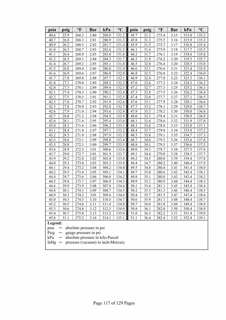
Page 117 of 129 Pages
°C kPa Bar °F psig psia°C kPa Bar °F psig psia 135.2 315.0 3.15 275.4 31.2 45.7 131.2 280.0 2.80 268.2 25.9 40.6 135.3 315.9 3.16 275.5 31.3 45.8 131.3 280.9 2.81 268.3 26.0 40.7 135.4 316.8 3.17 275.7 31.5 45.9 131.4 281.7 2.82 268.5 26.2 40.9 135.5 317.7 3.18 275.9 31.6 46.1 131.5 282.6 2.83 268.7 26.3 41.0 135.6 318.6 3.19 276.1 31.7 46.2 131.6 283.4 2.83 268.9 26.4 41.1 135.7 319.5 3.20 276.2 31.9 46.3 131.7 284.3 2.84 269.1 26.5 41.2 135.8 320.5 3.20 276.4 32.0 46.5 131.8 285.1 2.85 269.2 26.7 41.4 135.9 321.4 3.21 276.6 32.1 46.6 131.9 286.0 2.86 269.4 26.8 41.5 136.0 322.4 3.22 276.8 32.3 46.8 132.0 286.8 2.87 269.6 26.9 41.6 136.1 323.3 3.23 277.0 32.4 46.9 132.1 287.7 2.88 269.8 27.0 41.7 136.2 324.3 3.24 277.2 32.6 47.0 132.2 288.5 2.89 270.0 27.1 41.8 136.3 325.2 3.25 277.3 32.7 47.2 132.3 289.4 2.89 270.1 27.3 42.0 136.4 326.2 3.26 277.5 32.8 47.3 132.4 290.2 2.90 270.3 27.4 42.1 136.5 327.1 3.27 277.7 33.0 47.4 132.5 291.1 2.91 270.5 27.5 42.2 136.6 328.1 3.28 277.9 33.1 47.6 132.6 291.9 2.92 270.7 27.6 42.3 136.7 329.0 3.29 278.1 33.2 47.7 132.7 292.8 2.93 270.9 27.8 42.5 136.8 330.0 3.30 278.2 33.3 47.9 132.8 293.6 2.94 271.0 27.9 42.6 136.9 330.9 3.31 278.4 33.3 48.0 132.9 294.5 2.94 271.2 28.0 42.7 137.0 331.9 3.32 278.6 33.4 48.1 133.0 295.4 2.95 271.4 28.1 42.8 137.1 332.8 3.33 278.8 33.6 48.3 133.1 296.2 2.96 271.6 28.3 43.0 137.2 333.8 3.34 279.0 33.7 48.4 133.2 297.1 2.97 271.8 28.4 43.1 137.3 334.7 3.35 279.1 33.8 48.5 133.3 297.9 2.98 271.9 28.5 43.2 137.4 335.6 3.36 279.3 34.0 48.7 133.4 298.8 2.99 272.1 28.6 43.3 137.5 336.6 3.37 279.5 34.1 48.8 133.5 299.7 3.00 272.3 28.8 43.5 137.6 337.5 3.38 279.7 34.3 49.0 133.6 300.6 3.01 272.5 28.9 43.6 137.7 338.5 3.38 279.9 34.4 49.1 133.7 301.5 3.01 272.7 29.0 43.7 137.8 339.4 3.39 280.0 34.5 49.2 133.8 302.4 3.02 272.8 29.2 43.9 137.9 340.4 3.40 280.2 34.7 49.4 133.9 303.3 3.03 273.0 29.3 44.0 138.0 341.4 3.41 280.4 34.8 49.5 134.0 304.2 3.04 273.2 29.4 44.1 138.1 342.4 3.42 280.6 35.0 49.7 134.1 305.1 3.05 273.4 29.5 44.2 138.2 343.4 3.43 280.8 35.1 49.8 134.2 306.0 3.06 273.6 29.7 44.4 138.3 344.4 3.44 280.9 35.2 49.9 134.3 306.9 3.07 273.7 29.8 44.5 138.4 345.4 3.45 281.1 35.4 50.1 134.4 307.8 3.08 273.9 29.9 44.6 138.5 346.4 3.46 281.3 35.5 50.2 134.5 308.7 3.09 274.1 30.1 44.8 138.6 347.4 3.47 281.5 35.7 50.4 134.6 309.6 310 274.3 30.2 44.9 138.7 348.4 3.48 281.7 35.9 50.6 134.7 310.5 3.10 274.5 30.3 45.0 138.8 349.4 3.49 281.8 36.0 50.7 134.8 311.4 3.11 274.6 30.5 45.2 138.9 350.4 3.50 282.0 36.1 50.8 134.9 312.3 3.12 274.8 30.6 45.3 139.0 351.4 3.51 282.2 36.3 51.0 135.0 313.2 3.13 275.0 30.7 45.4 139.1 352.4 3.52 282.4 36.4 51.1 135.1 314.1 3.14 275.2 31.1 45.6
Legend: psia absolute pressure in psi Psig gauge pressure in psi kPa absolute pressure in kilo-Pascal InHg pressure (vacuum) in inch-Mercury

Page 118 of 129 Pages
EXPLODED DRAWING – REAR
20
21
14
1 2 3 4 5 6 7 8
9 10
11
12
18
13
17
16
19
15
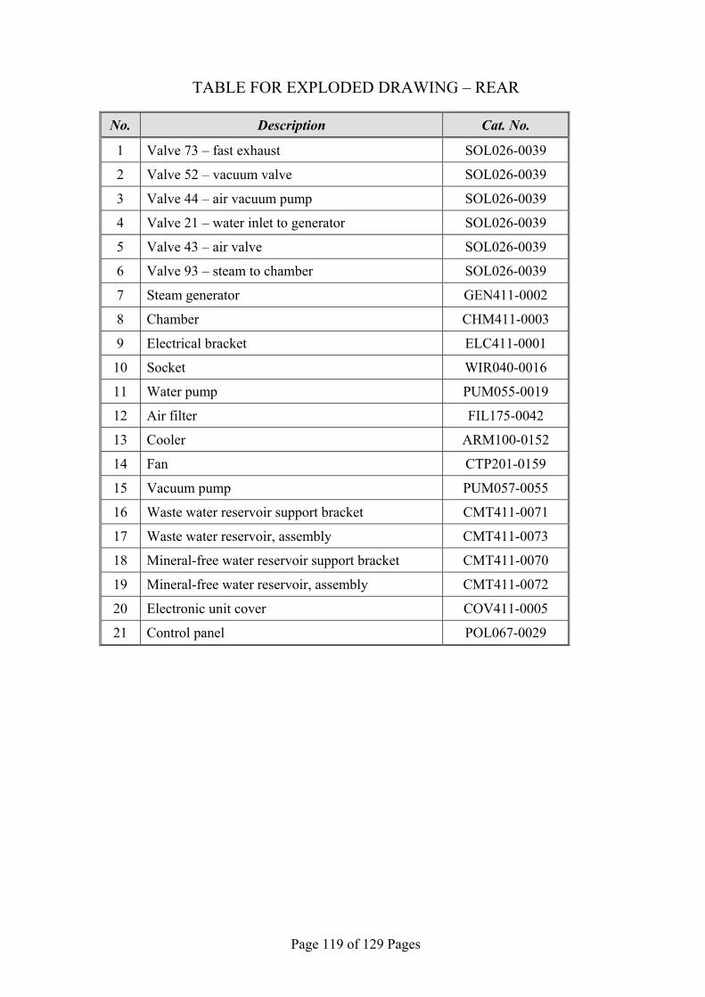
Page 119 of 129 Pages
TABLE FOR EXPLODED DRAWING – REAR
No. Description Cat. No.
1 Valve 73 – fast exhaust SOL026-0039
2 Valve 52 – vacuum valve SOL026-0039
3 Valve 44 – air vacuum pump SOL026-0039
4 Valve 21 – water inlet to generator SOL026-0039
5 Valve 43 – air valve SOL026-0039
6 Valve 93 – steam to chamber SOL026-0039
7 Steam generator GEN411-0002
8 Chamber CHM411-0003
9 Electrical bracket ELC411-0001
10 Socket WIR040-0016
11 Water pump PUM055-0019
12 Air filter FIL175-0042
13 Cooler ARM100-0152
14 Fan CTP201-0159
15 Vacuum pump PUM057-0055
16 Waste water reservoir support bracket CMT411-0071
17 Waste water reservoir, assembly CMT411-0073
18 Mineral-free water reservoir support bracket CMT411-0070
19 Mineral-free water reservoir, assembly CMT411-0072
20 Electronic unit cover COV411-0005
21 Control panel POL067-0029

Page 120 of 129 Pages
EXPLODED DRAWING – DOOR
7 5
4
9 10
11
6
13
3
8
15
16
12
14
2 1
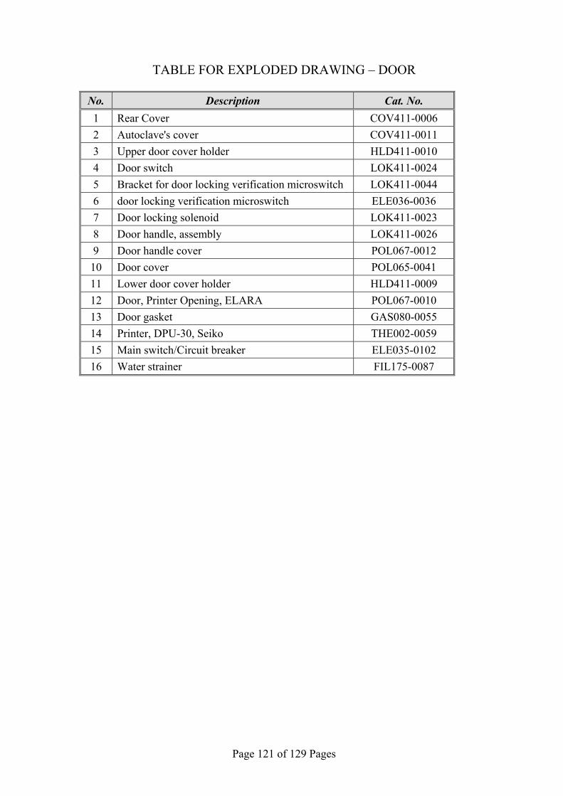
Page 121 of 129 Pages
TABLE FOR EXPLODED DRAWING – DOOR
No. Description Cat. No. 1 Rear Cover COV411-0006
2 Autoclave's cover COV411-0011
3 Upper door cover holder HLD411-0010
4 Door switch LOK411-0024
5 Bracket for door locking verification microswitch LOK411-0044
6 door locking verification microswitch ELE036-0036
7 Door locking solenoid LOK411-0023
8 Door handle, assembly LOK411-0026
9 Door handle cover POL067-0012
10 Door cover POL065-0041
11 Lower door cover holder HLD411-0009
12 Door, Printer Opening, ELARA POL067-0010
13 Door gasket GAS080-0055
14 Printer, DPU-30, Seiko THE002-0059
15 Main switch/Circuit breaker ELE035-0102
16 Water strainer FIL175-0087

Page 122 of 129 Pages
EXPLODED DRAWING – PT-100 AND CUT-OFF
6
9 7
18
1
20
2
13
22
21
8
3 4 5
12
16
17
19
14
10
15
11

Page 123 of 129 Pages
TABLE FOR EXPLODED DRAWING – PT-100 AND CUT-OFF
No. Description Cat. No. 1 Cooling coil PIP411-0002
2 Internal PT100 ELC258-0003
3 Chamber heater PT100 ELC258-0003
4 Chamber heater Cut-off 155˚C THE005-0016
5 Air filter opening cover POL067-0004
6 Air filter FIL175-0042
7 Validation port opening cover POL065-0006
8 Transformer, 2x115 / 2x12, 50/60 hz ELE035-0092
9 Ceramic connector for generator heater THE039-0036
10 Generator cut-off 170˚C THE005-0019
11 Adjustable Rear Leg WHE070-0035
12 Check valve Mondeo 1/4 ARM172-0008
13 Check valve Mondeo 1/4 ARM172-0008
14 Chamber heating element HEA010-0017
15 Adjustable Front Leg WHE070-0034
16 Pressure Switch, TY85 THE005-0006
17 Chamber pressure transducer, -1+3 Bar abs THE006-0006
18 Generator pressure transducer, -1+3 Bar abs THE006-0006
19 Chamber safety valve SVL029-0028
20 Steam generator safety valve SVL029-0028
21 Waste Water reservoir cover RES411-0006
22 Mineral-free water reservoir cover RES411-0005

Page 124 of 129 Pages
EXPLODED DRAWING – GENERATOR
No. Description Cat. No.
1 Heating element HEA016-0031
2 Water level electrode CMT196-0004
3 Manifold CMT253-0022
4 Elbow FIT100-0083
5 Elbow FIT100-0809
6 Generator body GEN411-0001
7 Drain plug PNE195-0161
6 7 5
2 3 1
4

Page 125 of 129 Pages
CONTROL UNIT
No. Description Cat. No.
1 Board, Electronic, AC, NOVA4-A2 CTP201-0165
2 Board, Electronic, Main, NOVA4-DN2, Elara CTP201-0164
3 Fuse 3.15 A FAST (chamber heater) ELE035-0128
4 Fuse 2A FAST (vacuum pump) ELE035-0009
5 Cable, Flat, for Printer, 50cm, 40P CTP201-0174
6 Fuse 2A FAST (water pump) ELE035-0009
6
3
4
5
2
1

Page 126 of 129 Pages
PARTIAL FRONT VIEW
No. Description Cat. No.
1 Isolation cover, rear of chamber Elara 11" (hidden) COV411-0008
2 Silicone gasket, waste water reservoir GAS080-0007
3 Silicone gasket, mineral free water reservoir GAS080-0007
4 Isolation Cover, Chamber, ELARA 11 COV411-0001
5 Keypad CPN064-0031
2
3
4
5
1
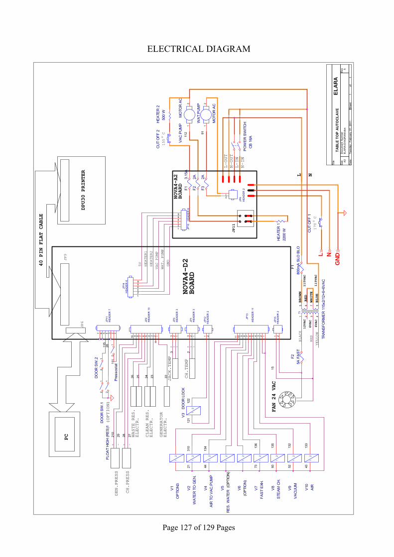
Page 127 of 129 Pages
ELECTRICAL DIAGRAM
N
22
133
JP2
HEA
DER
10
12345678910
CU
T O
FF 1
FLO
AT
HIG
H (R
ES
)11
2
FAN 24 VAC
V1
OP
TIO
N3
12
L
CH.TEMP
3
15
Pre
ssos
tat
12
GEN.PRESS
- +
Y
(OP
TIO
N)
HE
ATE
R 2
500
W
L-OUT
V10
AIR
12
CU
T O
FF 2
155 C
JACK.TEMP
(OPTION)
V9
VA
CU
UM
12
DPU30 PRINTER
115
134
R
V4
AIR
TO
VA
C.P
UM
P1
2
115VAC
-
VA
C P
UM
PM
OTO
R A
C
12
WAT. PUMP
BLACK
7313
6
L
JP6
CLEAN RES.
ELECTR.
WASTE RES.
ELECTR.
R
26
132
F13.
15A
DO
OR
SW
.11
2
JP1
HEA
DER
3123
JP9
112
N
CH.PRESS
93
NOVA4-A2
BOARD
6VAC
135
Y
HEATER1
25
43
JP15
HEA
DER
21 2
91
ELA
RA-
DIA
GR
AM
.dsn
5
TA
BL
E T
OP
AU
TO
CL
AV
E
A3
11
Tues
day
, Feb
ruar
y 01
, 20
11
Title
Size
Doc
umen
t Num
ber
Rev
Dat
e:S
heet
of
BROWN
GENERATOR
ELECTR.
52F1
800m
A S
LO B
LO
HEATER2
GN
D
V2
WA
TER
TO
GE
N.
12
WA
T.P
UM
P
MO
TOR
AC
12
5V
RED
F25A
FA
ST
L-IN
BLUE
JP13
HEA
DER
11
1234567891011
EL
AR
A
HE
ATE
R 1
2200
W
2
V5
RE
S. W
ATE
R1
2
YELLOW
Y12
1
T1
TRA
NS
FOR
ME
R 1
15x2
/12+
6+6V
AC
15 6
2
8
3 4
7
24
PC
N-IN
JP11
HEA
DER
7
1234567
122
DO
OR
SW
.2 12
PO
WE
R S
WIT
CH
CB
16A
21
23
12VAC
310
115VAC
F22A
+
JP3
HEA
DER
3123
JP10
HEA
DE
R 6
123456
44
JP11
N-OUT
JP9
HEA
DE
R 2
12
o6VAC
V3
DO
OR
LO
CK
12
V6
(OP
TIO
N)
12
Y
RED
F32A
170 C
NOVA4-D2
BOARD
40 PIN FLAT CABLE
28
VAC PUMP
210
GND
WHITE
V8
STE
AM
CH
.1
2
o
2729
V7
FAS
T E
XH.
12
26
JP12
HEA
DER
21 2
JP14
HEA
DER
6
123456
111
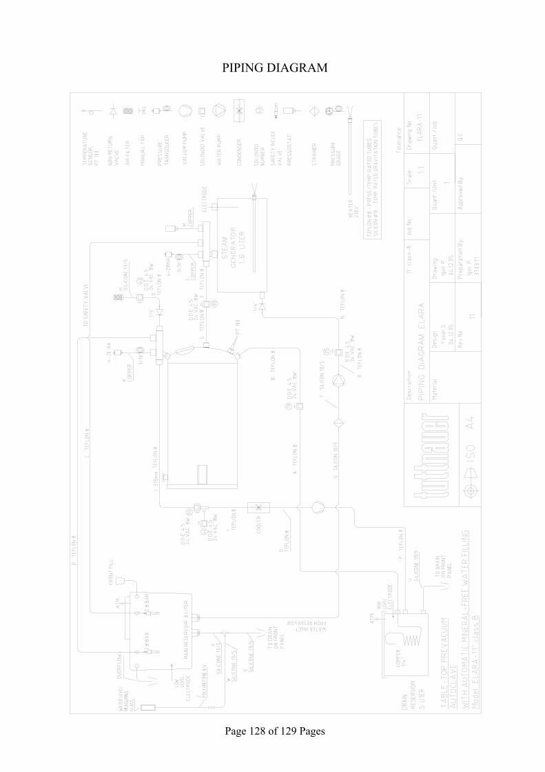
Page 128 of 129 Pages
PIPING DIAGRAM
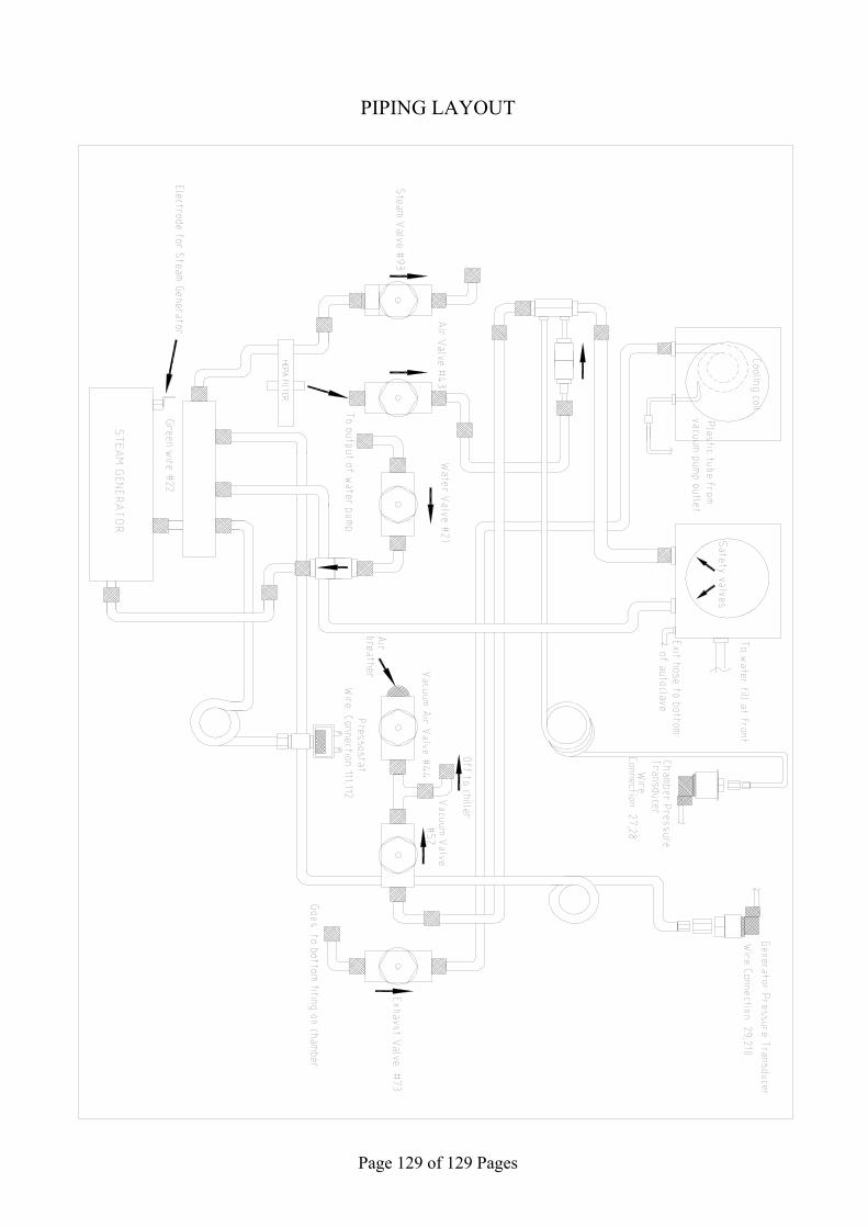
Page 129 of 129 Pages
PIPING LAYOUT