man205-0176-000e rev e
TRANSCRIPT
TECHNICIAN MANUAL
Electronic Table -Top Autoclaves models 1730, 2340, 2540, 3140, 3850, 3870
E, EK, EA & EKA
Cat. No. MAN205-0176-000E Rev. E Tuttnauer Europe b.v., Paardeweide 36, 4824 EH, Breda, P.O. Box 7191, 4800 GD Breda, Netherlands. +31/76-5423510, Fax: +31/76-5423540
1
TABLE OF CONTENTS PARAGRAPH PAGE NO. 1 INTRODUCTION ................................................................................................ 4 2 SYMBOL DESCRIPTION................................................................................... 4 3 TESTS ................................................................................................................... 5
3.1 Installation Tests....................................................................................... 5 3.2 Periodical Tests......................................................................................... 5
4 WATER QUALITY............................................................................................... 6 4.1 Water for Generating Steam .................................................................... 6 4.2 Reverse Osmosis........................................................................................ 6
5 IN-OUT TEST ...................................................................................................... 7 6 TROUBLESHOOTING........................................................................................ 8 7 REPLACEMENT OF COMPONENTS ............................................................ 14
7.1 Safety Tests after Repair......................................................................... 14 7.2 Replacing the Safety Valve..................................................................... 15 7.3 Replacing the Air Relief Valve ............................................................... 16 7.4 Replacing the Air-Relief/safety-relief Valve block ................................ 17 7.5 Dismantling the Outer Covers of the Autoclave.................................... 18 7.6 Replacing Heating elements................................................................... 19 7.7 Replacing the Temperature Safety Thermostat ..................................... 20 7.8 Replacing the Cut-Off Thermostat......................................................... 21 7.9 Cleaning and Replacing the Water Level Electrodes............................ 22 7.10 Replacing the Drain Valve ..................................................................... 23 7.11 Replacing the Pressure Gauge ............................................................... 24 7.12 Replacement of the Door Cover ............................................................. 25 7.13 Replacing the Printer.............................................................................. 26 7.14 Replacing the Door Switch..................................................................... 28 7.15 Cleaning water inlet strainer.................................................................. 29 7.16 Replacing the circuit breaker ................................................................. 30 7.17 Fuses and Circuit Breaker Data ............................................................ 31 7.18 Replacing the water pump...................................................................... 32 7.19 Replacing the Door Bellows ................................................................... 33 7.20 Replacing the Electronics Box ............................................................... 34 7.21 Validation................................................................................................ 35
8 DESCRIPTION AND FUNCTION OF DIP-SWITCHES............................... 36 8.1 Changing the parameters ....................................................................... 37
9 TEST POINTS - TABLE AUTOCLAVE (AJUNC 3 BOARD) ........................ 38 10 DETAILED DESCRIPTION OF ELECTRONIC SUB-ASSEMBLIES ......... 39
10.1 PREDG board ......................................................................................... 39 10.2 AJUNC 3 Board ...................................................................................... 41

2
TABLE OF CONTENT (Cont.) PARAGRAPH PAGE NO.
11 CALIBRATION AND TESTING PROCEDURE ................................. 43 11.1 Check-Up of Voltages ............................................................................. 43 11.2 Calibration Procedure ............................................................................ 43
12 LIST OF SPARE PARTS................................................................................... 44 13 PRESSURE VS TEMPERATURE FOR SATURATED STEAM.................... 48 14 VALVES NUMBERING .................................................................................... 56

3
TABLE OF CONTENT (Cont.) DRAWINGS PAGE NO.
AJUNC 3 Board ........................................................................................................... 42 Vessel Assembly ........................................................................................................... 52 Door Tightening Bolt – Assembly ............................................................................... 53 Outer Cabinet - Assembly ............................................................................................ 54 Water Reservoir............................................................................................................ 54 Water Reservoir............................................................................................................ 55 Water Outlet Strainer................................................................................................... 55 Piping Diagram for Models 1730 E and EK............................................................... 58 Piping Diagram for Models: E and EK Except 1730 ................................................ 59 Piping Diagram for Models: EA And EKA ................................................................ 60 Electrical Diagram for Models 1730 E, EK................................................................ 60 Electrical Diagram for Models 1730 E, EK................................................................ 61 Electrical Diagram for Models 2340/2540 E, EK....................................................... 62 Electrical Diagram for Models 2340/2540 EA, EKA ................................................. 63 Electrical Diagram for Model 3140 E......................................................................... 64 Electrical Diagram for Models 3850/3870 E, EK....................................................... 65 Electrical Diagram for Models 3850/3870 EA, EKA ................................................. 66
4
1 INTRODUCTION This manual, together with the operator’s manual, forms the complete edition
of the Operation and Maintenance instructions. This manual is intended for the use of the technician. It is forbidden for unqualified and unauthorized personnel to service the autoclave in accordance with the instructions in this manual. Any unauthorized service may result in the invalidation of the manufacturer’s guarantee.
The qualified technician shall be an authorized electrician with the right qualifications in electronics and shall be familiar with the local technical/electrical regulations.
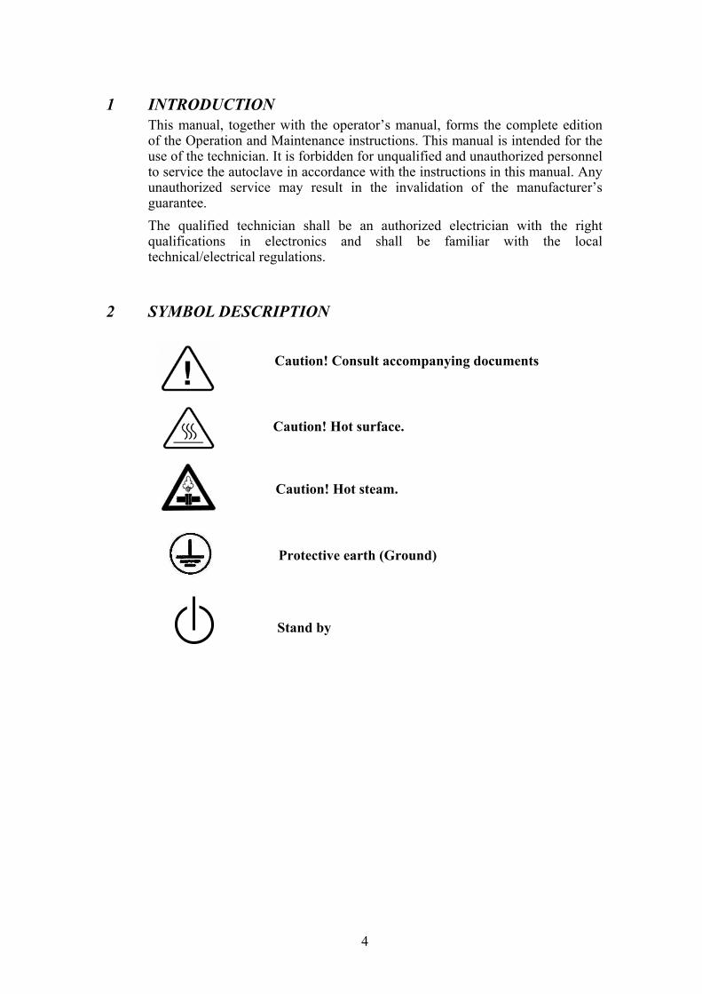
2 SYMBOL DESCRIPTION
Caution! Consult accompanying documents
Caution! Hot surface.
Caution! Hot steam.
Protective earth (Ground)
Stand by

5
3 TESTS 3.1 Installation Tests The service technician shall perform the following preliminary
checks before operating the autoclave: a. Leveling Check Check that the autoclave is leveled. b. Leakage current test Check the precise operation of the earth leakage relay. c. Continuity Check Check the continuity of the grounding connection. d. Safety Check Check the safety elements; safety valve and the door locking
mechanisms. e. Programs Check Run basic programs of the autoclave and check the operation
sequences, the sterilization parameters etc. f. Integrity Check Perform a visual check to verify that there are no dents, scratches,
broken gauges, etc. g. Validation Validate the sterilization cycles, taking in consideration the
interface of packaging/goods/autoclave. After the above steps are performed, the autoclave is ready for operation. 3.2 Periodical Tests
ERIOD TEST
1 months Test the safety valve by operating it.
6 months Remove the autoclave’s cover, tighten the heaters’ screws and electrical connections, valves and connectors in the control box. Check the continuity of the grounding connections. Check the temperature and pressure calibration. Perform validation of the autoclave. Check the precise operation of the earth leakage relay. Check that the autoclave is leveled. Check the safety elements; safety valve, safety and cut-off thermostats door locking mechanisms. Run basic programs of the autoclave and check the operation sequences, the sterilization parameters etc. Check the water reservoir, piping, plastic parts and electric wires. Check and tighten the piping joints to avoid leakage. Check and tighten all screw connections in the control box, heaters and valves and instrumentation.
Year
Calibrate the temperature and pressure once a year or in reference to local rules or regulations (refer to the section on Calibration).
5 years Observe the closing device for excessive wear Safety tests (pressure vessel, efficiency, electrical) shall be performed in accordance with local rules or regulations, by an authorized inspector.

6
Only an authorized technician shall perform the 6-months and yearly tests!
4 WATER QUALITY 4.1 Water for Generating Steam The distilled or mineral – free water supplied to the sterlizer shall be
according to the table below: Physical Characteristics and Maximum acceptable contaminants
levels in water or steam, for sterlizers (In compliance with ISO 11134 and ISO 13683).
Evaporate residue < 15 mg/l
Silica < 2 mg/l
Iron < 0.2mg/l
Cadmium < 0.005 mg/l
Lead < 0.05 mg/l
Rest of heavy metals < 0.1 mg/l
Chloride < 3 mg/l
Phosphate < 0.5 mg/l
Conductivity < 50 µs/cm
pH 6.5 to 8
Appearance Colourless, clean, without sediment
Hardness < 0.1 mmol/l
Compliance with the above data should be tested in accordance with acknowledged analytical methods, by an authorized laboratory.
Attention: We recommend testing the water quality once a month. The use of
water that does not comply with the table above may have severe impact on the working life of the sterilizer and can invalidate the manufacturer’s guarantee.
4.2 Reverse Osmosis A Reverse Osmosis system may be used to improve the quality of the
water used to generate steam in the autoclave chamber. The use of mineral free will contribute to better performance and longer life of the autoclave.

7
5 IN-OUT TEST Before performing any trouble shooting on the autoclave, perform an “in-out
test”. In this test the technician tests all the components of the system as follows: 1. Turn on the autoclave. Note: if, for any reason, one of the parameters is corrupted and out of
range, the autoclave will perform an automatic reset to the parameters set by the manufacturer upon turning on the autoclave.
2. Press the Up button until the autoclave beeps. This beep indicates that the autoclave is in “IN-OUT TEST” mode.
3. Release the button. 4. To proceed, press the UP button. Each time the UP button is pressed the
test advances one step, and the tested component is displayed on the display. 5. When a solenoid is tested, verify that it is activated by touching it with a
screwdriver. If the solenoid is magnetized – it is activated. 6. To stop the IN-OUT TEST press the Up button.
DISPLAYED
NOTICE ITEM ACTIVATED REMARKS
WATER V + WATER PUMP Water valve + water pump Verify water enters the chamber
EXH Exhaust valve
HEATERS Heating elements Begins heating. Do not maintain for long time since it works without water.
AIR Air valve WATER P Water pump Verify you hear the pump is operating.
DOOR L N/A N/A
PUMP Air pump Verify you hear the pump is operating.
FLOAT 1 Water level switch indicates “no water”
FLOAT 0 Water level switch indicates “enough water”
Change position of the float switch and verify that the display reflects the change.
DOOR 0 Door switch indicates “closed door”
DOOR 1 Door switch indicates “open door”
Press and release the door switch and verify that the display reflects the change.
THERM O Safety thermostat grounded
THERM 1 Safety thermostat not grounded
PT100 Temperature sensor Displays ambient temperature.
PRESSURE Pressure transducer Open door and verify ambient temperature is displayed.
ELECTRODE X Water level electrode
X may vary between 100 and 255. 255 indicate “no water in chamber” 150 indicates “water in chamber” or “electrode short- circuited”
8
6 TROUBLESHOOTING a) At the customer’s location, avoid replacing any component, which is not
connected to a socket or to a flat cable. If necessary, replace the complete board or box. If problem persists service the autoclave at the service lab.
b) Whenever the AJUNC3 board of the complete electrical assembly (CB90030) is replaced without replacing the pressure transducer, or after replacing the pressure transducer, the pressure must be re-calibrated.
c) When working with the autoclave, DISCONNECT the power cord from the socket or turn the circuit breaker OFF.
6.1 Turning on the system, no response a) Check the voltage at the terminal (is the power cord damaged?
change the power cord if necessary. b) Check the flat cable connecting the PREDG and the AJUNC3,
replace it if necessary. c) Check the circuit breaker, if it is off, turn it on. d) Check the cut - off position pushes it in and turn it on. e) Check the power supply input fuse and replace the fuse if
necessary. If the network input is o.k., the problem must be with one of the
elements along the line, the power supply, the PREDG or AJUNC boards and the elements they are connected to.
f) Check the voltages by means of connecting the Test board to JP14 on the AJUNC 3 board as detailed in the voltage checking procedure.
6.1.1 If there is no 12V nor 5V a) Does the power supply receive the network voltage? b) Is the power supply output OK? Disconnect the
connector to JP3 (AJUNC3 board) and check for voltage on the female connector no. 12V at the female connector indicates a faulty power supply that should be replaced. At the client’s location replace the whole electrical box (C B 90030). 12V at that location indicates that the power supply is functioning and that the problem is somewhere else.
c) Check the AJUNC3 board. Disconnect the fan (JP5), the valves (JP2) and the printer (if present). If disconnecting any of these elements brings up the voltage, that element is damaged and has to be replaced.
d) Disconnect the PREDG board and the printer from the AJUNC 3 board. If any of these elements are faulty, 5V appears as it is disconnected. If there is still no 5V, the power supply is damaged.
6.2 System is ON - display is lit If the other LEDS are functioning the display is most likely damaged.
Replace the PREDG board.
9
6.3 System ON, display lit, erroneous or fragmented digits The reasons for that may be faulty Real Time Clock, displays or
microcontroller. Replace them or replace the complete PREDG board.
6.4 System ON, display lit, digits are not visible ♦ Check for 5 V between TP1and TP17 ♦ If yes, calibrate POT 1 on PREDG board. ♦ If digits remain invisible, this may be due to a faulty display or a
faulty microcontroller. Replace them or replace the complete PREDG board.
6.5 System ON, key responds without beeping The problem may be with the buzzer or the buzzer driver. Replace the
complete PREDG board, replace the buzzer or transistor 2N2222A, Q1.
6.6 Exhaust valve is always on The problem could be with the solenoid, the transistors, or the digital
control, or a bad connection. ♦ Check and connect or replace all connections to and from the
exhaust valve. ♦ The problem could be with Q4 or Q5 on the PREDG board. If after
pressing START and the water enters the chamber, the voltage on TP11 is between 10V - 12V the control and the transistors are O.K. If not, replace the PREDG board. At this point disconnect connector JP2 from the AJUNC3 board, and check the valve’s control.
If the connection to the valve is OK, (please refer to the wiring diagram) there must be a mechanical problem with the valve or the solenoid may be damaged.
If the control is faulty, check and connect the flat cable between AJUNC3 and PREDG, replace the cable if necessary. If this does not help, there may be a problem in the LATCH DRIVE at U4 in PREDG. In that case the electronics unit should be replaced.
6.7 Exhaust valve is always off ♦ Check and connect or replace the connector between the
EXHAUST valve and the AJUNC3. ♦ Repeat transistors and control checks as in 7.6 but this time the
voltage for the transistors should be vice versa: 0.0-1.0 DC. volt (on TP11) for open position.
♦ Check and replace the valve or the coil.
6.8 Water valve is always on and there is a continuous flow of water into the chamber. ♦ Check the valve’s solenoid and the control circuit as you have
checked the respective exhaust valve and circuit. The valve could also be checked by pressing the MANUAL water inlet key. If water flows in the chamber, or if there is no flow of water once the system is initiated, the valve and its control are o.k., but the water level detector electrode may be damaged, or the connection between the electrode and the circuit may be bad.
♦ Check wire and connector connecting electrode to AJUNC3 board.

10
6.9 Inlet key does not let water into the chamber ♦ Check if this key is faulty. If it beeps when pressed it is O.K. if not,
replace the keypad. If this does not help, replace the complete PREDG and keypad unit.
♦ Check the float at the water reservoir by manipulating it using a screwdriver or a tool and repair/replace it. If the float is functioning, the problem could be with the control circuit at the PREDG board: the test board between TP1 (GND) and TP10 (water valve): GOOD = 0.0V to 0.05V.
♦ If the control is OK, there may be a problem with the valve itself or with its connector.
♦ Check and replace the coil if necessary.
6.10 Pressure stays close to 100 kPa (0 psi), temperature does not exceed 110 - 115°C (207°F) or, water inlet lasts a longer time than usual
This phenomenon is most likely due to malfunction of the air valve. The air valve’s normal operation is as follows:
OPEN whilst turning the system on, OPEN throughout WATER INLET and HEAT until temperature has reached 90°C or 194°F, CLOSED from that stage on, and OPEN during DRY.
The valve’s control on the AJUNC3 board should act as follows: 0.0V = valve OPEN 5.0V = valve CLOSED If the problem lies on the AJUNC 3 board it should be replaced. It is
recommended to replace both the AJUNC3 and the solenoid because a damaged solenoid may affect the AJUNC3 board. If the control circuit on the AJUNC3 is OK, the problem is probably with the PREDG board.
6.11 Heaters are always ON or OFF Warning: If you need to tighten a screw, make sure to do so only when
the power cord is disconnected. ♦ Check the heaters connections. ♦ Check the cutoff thermostat position and turn it clockwise to the end. ♦ Check the control at TP1 and TP12 for ON = 0.0V, OFF = 5v ♦ Check connections between AJUNC3 to SSR at TP4. ♦ Does AC voltage enter the SSR at AC connector and SSR pin 2? ♦ Is SSR output the AC voltage? Check AC connector and at SSR pin 1. ♦ Is the control OK? Check the SSR for 5.0V between pins 3&4. If
control is OK, but SSR output is not the AC voltage, replace the SSR.
6.12 Heaters o.k. but autoclave does not reach sterilization temperature ♦ Check and calibrate the cutoff position. ♦ Check and clean/ replace leakage at the exhaust valve. ♦ It is also possible that there is a calibration variance, check the
GAIN pressure calibration, perhaps it should be lowered or, the GAIN temperature should be increased.
♦ Another possibility is that insufficient water level in the chamber does not allow the pressure to build up. Check the water level detector electrode, or the leveling of the autoclave.
11
6.13 Fan is not on during the cycle ♦ Check and connect properly the FAN’S connector at JP5 on the
AJUNC3 board. ♦ Disconnect FAN and check the control TP1 and TP-13: ON = 0.0V OFF = 5.0V
6.14 Pressure display is incorrect (discrepancy between ANALOG and Digital displays) ♦ Re-calibrate the displayed pressure by manipulating POT2 on the
AJUNC3 board. ♦ Check the MPX2200A pressure transducer between TP2 & TP3: ♦ Working condition = 20mV for 100 kPa. ♦ If pressure transducer is faulty, replace it, and calibrate it according
to the instructions in the Chapter on Calibration. ♦ If the pressure transducer is OK but display incorrect, replace the
AJUNC3. 6.15 Temperature display is incorrect
♦ Check the temperature sensor PT100. ♦ Check the calibration of the temperature circuit.
6.16 ADD WATER (to reservoir) Indicator is always ON ♦ Check the connector at JP2 on AJUNC3 board. ♦ Check if the float at the water reservoir is stuck. ♦ Check the input: TP1 and TP8 FULL = 0.0V, EMPTY = 5.0V ♦ Check the float’s buffer, it may be, the input at U5 on PREDG is
damaged. PREDG board should be replaced.
6.17 DOOR CLOSED indicator is always ON/OFF ♦ Check and fine tune the switch at the upper front left side of the
autoclave, while the door is open. Check the switch with an ohmmeter. If the microswitch is damaged, replace it.
♦ Check the LED, if it is burnt, change the PREDG and keypad. ♦ Check the connector between microswitch and AJUNC3 on TP2. ♦ Check the connection on GND to the microswitch with an
ohmmeter and be sure that the GND to the micro switch. ♦ If the switch and microswitch are OK, buffer at U5on PREDG may
be damaged, in that case, replace the PREDG board. Note: If replacing the microswitch is necessary, VERIFY THE ELECTRIC
CORD IS DISCONNECTED.
6.18 Start key does not let water into the chamber ♦ Follow previous procedures for float, controls and valve. ♦ Check the water level electrode: Connect TP1 and TP6, close the
door, press START. ♦ If 4V the electrode is short circuited or faulty. Same procedure may
be followed without pressing START, if the door is open.

12
6.19 Back-up memory does not function does not function, new parameters are not stored in memory ♦ The backup battery in the Real Time Clock is damaged so
component U2 should be replaced.
6.20 LOW PRESSURE message is displayed This is usually due to insufficient water inside the chamber.
♦ If the water valve is OK, the electrode detecting the water level may be damaged. It may detect water in the chamber although it is actually empty.
♦ The normal operation procedure of the electrode is to let water in the chamber 8 additional seconds after it has detected a sufficient water level.
♦ If the electrode is short circuited, it may let water into the chamber for only a few seconds.
♦ Check if there is any contact between the electrode and the chamber. Use an ohmmeter for that purpose. Make sure none of the tools to be sterilized has any contact with the electrode. If the problem persists, the electrode circuit on the AJUNC3 board may be short circuited or damaged.
6.21 Clock and date are inaccurate, new data is not stored in memory
♦ If new data (operator’s own parameters) is not kept in memory, then the backup battery is down, and the same unit has to be replaced as the backup battery is an integral part of the Real Time Clock. Change the Real Time Clock (U2), on PREDG.
♦ The battery manufacturer offers a ten-year guarantee, but it is recommended to change the Real Time Clock including the integrated backup battery once every 8 years.
6.22 Unpredicted function of the autoclave
♦ Check the input and output voltages. Disconnect the printer as it may be causing a short circuit if it is faulty. If the problem persists, the keypad may be short circuited, replace it with the PREDG board, if that does not help, replace the complete electronic system.
6.23 Displaying of low temperature If LOW TEMPERATURE is displayed, the following should be
checked: 1. The proper amount of water is in the chamber. 2. The air jet has to be checked and cleaned.
13
6.24 Memory reset To reset the memory of the autoclave control unit backed up by a
battery, proceed as follows: Verify that there is no pressure in the autoclave chamber. 1. Turn the main switch to OFF position. 2. Press the STOP key. At the same time turn the main switch to ON
position. 3. Keep pressing the STOP key until the program parameters are
displayed. 4. Set the Sterilization temperature, Sterilization time, Date and Time. 5. Repeat the procedure of automatic water filling.
6.25 Cycle counter reset To reset the cycle counter proceed as follows:
1. Press the STOP key a few times, till CODE 102 is displayed. 2. Press the UP key (8) up to CODE 134. 3. Press any key to continue.
The counter is now reset.
6.26 EKA ONLY - Air pump and valve always ON or OFF ♦ Check the S.S.R2 in the electric box. ♦ Check if TP 18 is in 0.0V if on and 5.0V if off, if yes replace
PREDG. If not replace the AJUNC3 board.
6.27 EKA - Air pump is always on, valve is off
♦ The problem is in the pump or in SSR2 located in the electric box.
6.28 Pump is operating but no or low water flow.
Check pipes connecting the water reservoir, strainer and pump. 1 Air accumulates at the pump inlet. Disconnect pipe from the pump,
let water flow to remove air accumulation and reconnect pipe. 2 Pipe is clogged. Clean pipe. 3 Strainer is clogged. Clean strainer according to instructions.
6.29 Water does not exit chamber. Outlet strainer is clogged. Clean strainer according to instructions.

14
7 REPLACEMENT OF COMPONENTS 7.1 Safety Tests after Repair
ATTENTION! After every repair or dismantling the enclosure, the autoclave should pass two safety electrical test by the Service Engineer. The following shall be performed:
1. Enclosure Leakage Current Test. Every autoclave should pass this test as follows:
1. Connect the electrical cord to the autoclave. 2. Turn on the main switch and the circuit breaker. 3. Short-circuit the L and N pins on the cord's plug. 4. Connect the Short-circuit pins to the L pole on the Megger. 5. Connect the earth pins to the earth pole on the Megger. 6. Impose an electrical potential of 500-1000V on the tested
autoclave. The insulation resistance should be at least 2 MΩ. The test is successful if there was no leakage. 2. Protective Earth Impedance Test
1. Connect the grounding pin of the power cord plug to one pole of an Ohmmeter.
2. Connect any other metallic part (preferable – the metallic part of the locking screw) to the second pole of the Ohmmeter.
3. The resistance should not exceed 0.3 Ω.
After performing these tests, the Service Engineer should complete and sign the Work Order.
15
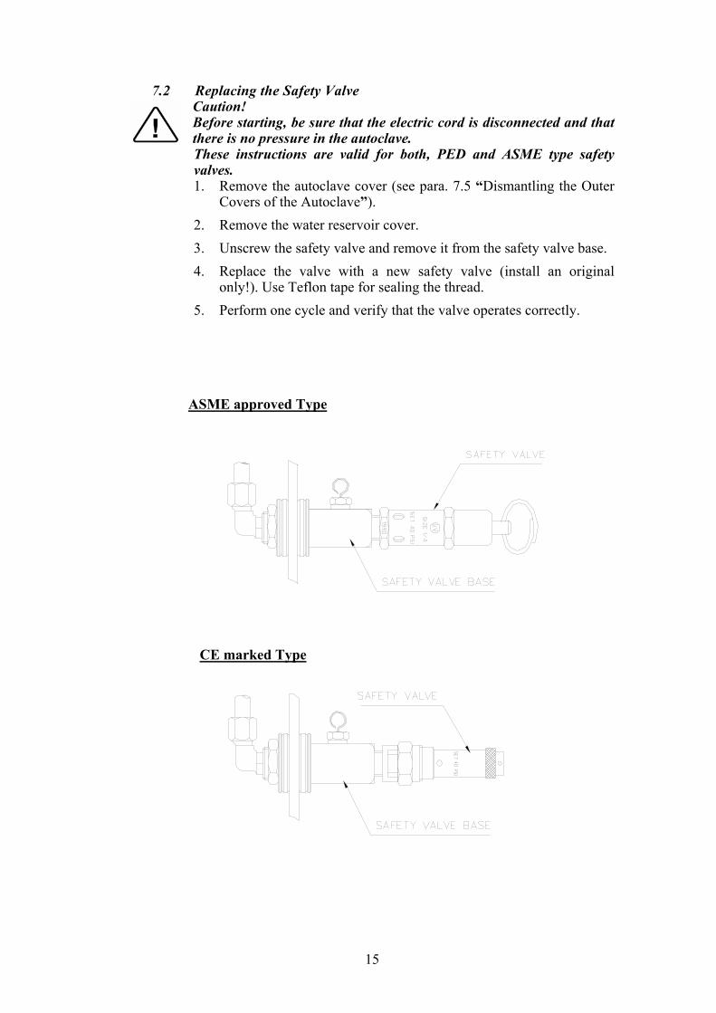
7.2 Replacing the Safety Valve Caution! Before starting, be sure that the electric cord is disconnected and that there is no pressure in the autoclave.
These instructions are valid for both, PED and ASME type safety valves. 1. Remove the autoclave cover (see para. 7.5 “Dismantling the Outer
Covers of the Autoclave”). 2. Remove the water reservoir cover. 3. Unscrew the safety valve and remove it from the safety valve base. 4. Replace the valve with a new safety valve (install an original
only!). Use Teflon tape for sealing the thread. 5. Perform one cycle and verify that the valve operates correctly.
Typeapproved ASME
TypeCE marked

16
7.3 Replacing the Air Relief Valve Caution! Before starting, be sure that the electric cord is disconnected and that there is no pressure in the autoclave.
1. Remove the autoclave cover (see para. 7.5 “Dismantling the Outer
Covers of the Autoclave”). 2. Remove the water reservoir cover. 3. Remove the water reservoir silicon gasket. 4. Unscrew the air relief Valve with a 10 mm wrench and remove it
from the safety valve base. 5. Replace the valve with a new air relief (install an original only!).
use Teflon tape for sealing the thread. 6. Test any autoclave cycle to verify that the valve operates correctly.

17
7.4 Replacing the Air-Relief/safety-relief Valve block Caution! Before starting, be sure that the electric cord is disconnected and that there is no pressure in the autoclave.
In case the water reservoir is deeply contaminated (soil, lime stone. etc.)
it is recommended to replace the entire unit. 1. Remove the autoclave cover (see para. 7.5 “Dismantling the Outer
Covers of the Autoclave”). 2. Remove the water reservoir cover. 3. Remove the water reservoir silicon gasket. 4. Unscrew and remove nut (1) with a ½” wrench. 5. Remove angle 1/8”-1/4” (2) from the relief valve base. 6. Unscrew and remove nut (3). 7. Remove the air-relief-safety valve block (4). 8. Install the new unit using Teflon tape for sealing the thread. 9. Perform one cycle and verify that the valve operates correctly.
L:\\.doc

18
7.5 Dismantling the Outer Covers of the Autoclave Caution! Before starting, disconnect the instrument from the power source and ensure that there is no pressure in the autoclave. Allow the autoclave to cool before removing outer covers. 1. Remove the screws holding the rear cover (1). 2. Remove the screws holding the cover to the base (2). 3. On EA and EKA models dismantle the air filter from the service
opening cover (3).
3.1. Remove the screws holding the filter cover (on EA, EKA). 4. Remove the grounding wires from the cover. 5. Pull the cover upwards.
19
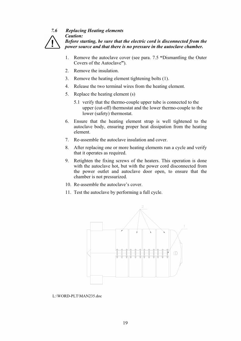
7.6 Replacing Heating elements Caution: Before starting, be sure that the electric cord is disconnected from the power source and that there is no pressure in the autoclave chamber.
1. Remove the autoclave cover (see para. 7.5 “Dismantling the Outer
Covers of the Autoclave”). 2. Remove the insulation. 3. Remove the heating element tightening bolts (1). 4. Release the two terminal wires from the heating element. 5. Replace the heating element (s)
5.1 verify that the thermo-couple upper tube is connected to the upper (cut-off) thermostat and the lower thermo-couple to the lower (safety) thermostat.
6. Ensure that the heating element strap is well tightened to the autoclave body, ensuring proper heat dissipation from the heating element.
7. Re-assemble the autoclave insulation and cover. 8. After replacing one or more heating elements run a cycle and verify
that it operates as required. 9. Retighten the fixing screws of the heaters. This operation is done
with the autoclave hot, but with the power cord disconnected from the power outlet and autoclave door open, to ensure that the chamber is not pressurized.
10. Re-assemble the autoclave’s cover. 11. Test the autoclave by performing a full cycle.
L:\WORD-PLT\MAN235.doc

20
7.7 Replacing the Temperature Safety Thermostat The autoclave is supplied with a temperature thermostat, which protects
the heaters and autoclave against overheating, during the dry cycle. This device reconnects automatically when the chamber cools down.
Caution Before starting, disconnect the instrument from the power source and ensure that there is no pressure in the autoclave. Allow the autoclave to cool before removing outer covers.
The temperature safety thermostat is located on the lower side of the
fuse and socket panel on the rear of the autoclave.
1. Remove the rear cover. 2. Loosen the heating band. 3. Unscrew the thermostat and replace it with a new one. 4. Perform any dry cycle to verify that the temperature safety
thermostat disconnects the heating units.
Safety Thermostat

21
7.8 Replacing the Cut-Off Thermostat This thermostat cuts out power to the autoclave, in the event that all
other safety means do not function. For example: If the safety thermostat is defective and the temperature
continues to rise, then the cut-off thermostat cuts out the power to the autoclave. In order to restart the operation press the Reset Button. If the autoclave is operated according to the instructions, and the thermostat again cuts out, the Cut-Off Thermostat must be replaced. Caution Before starting, disconnect the instrument from the power source and ensure that there is no pressure in the autoclave. Allow the autoclave to cool before removing outer covers.
The Cut-Off Thermostat is located on the upper side of the fuse and
socket panel on the rear of the autoclave.
1. Remove the rear cover. 2. Loosen the heating band. 3. Unscrew the thermostat and replace it with a new one.
Cut-Off Thermostat
Reset Button
22
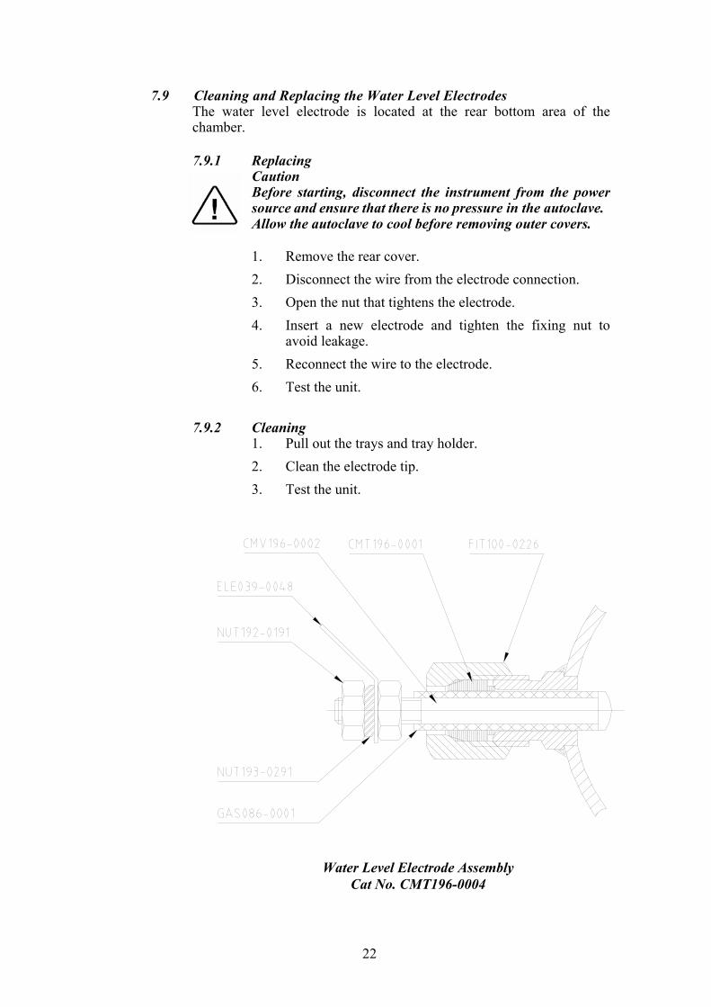
7.9 Cleaning and Replacing the Water Level Electrodes The water level electrode is located at the rear bottom area of the
chamber.
7.9.1 Replacing Caution Before starting, disconnect the instrument from the power source and ensure that there is no pressure in the autoclave. Allow the autoclave to cool before removing outer covers. 1. Remove the rear cover. 2. Disconnect the wire from the electrode connection. 3. Open the nut that tightens the electrode. 4. Insert a new electrode and tighten the fixing nut to
avoid leakage. 5. Reconnect the wire to the electrode. 6. Test the unit.
7.9.2 Cleaning
1. Pull out the trays and tray holder. 2. Clean the electrode tip. 3. Test the unit.
Water Level Electrode Assembly
Cat No. CMT196-0004

23
7.10 Replacing the Drain Valve Caution! Before starting, disconnect the instrument from the power source and ensure that there is no pressure in the autoclave. Allow the autoclave to cool before removing outer covers.
1. Remove the autoclave cover (see para. 7.5 “Dismantling the Outer
Covers of the Autoclave”). 2. Disconnect the drainpipe from the valve, using a 9/16” wrench. 3. Remove the nut (3) and the “ring for drain valve” (2). 3. Remove the drain valve (1) from the panel. 4. Install a new valve according to the drawing below. 5. Verify that there is no leakage.
CMT240-0020 CMT240-0003 VLV170-0066
Item Cat No.
1 SRV000-0224
2 SRV000-0232
24
7.11 Replacing the Pressure Gauge
Caution! Before starting, disconnect the instrument from the power source and ensure that there is no pressure in the autoclave. 7.11.1 Models 2340, 2540
1. Remove the door cover. 2. Remove the pressure gauge from the door. 3. Install the new pressure gauge using Teflon tape for
sealing the thread. 4. Operate the autoclave and verify that there is no
leakage. 5. Install the door cover. 6. Readjust the screw pressing the door microswitch (see
para. 7.11, Replacement of the Door Cover).
7.11.2 Models 3140, 3850, 3870 1. Remove the autoclave cover (see para. 7.5
“Dismantling the Outer Covers of the Autoclave”). 2. Remove the pressure gauge from the panel. 3. Install the new pressure gauge using Teflon tape for
sealing the thread. 4. Operate the autoclave and verify that there is no leakage. 5. Install the autoclave cover.
25
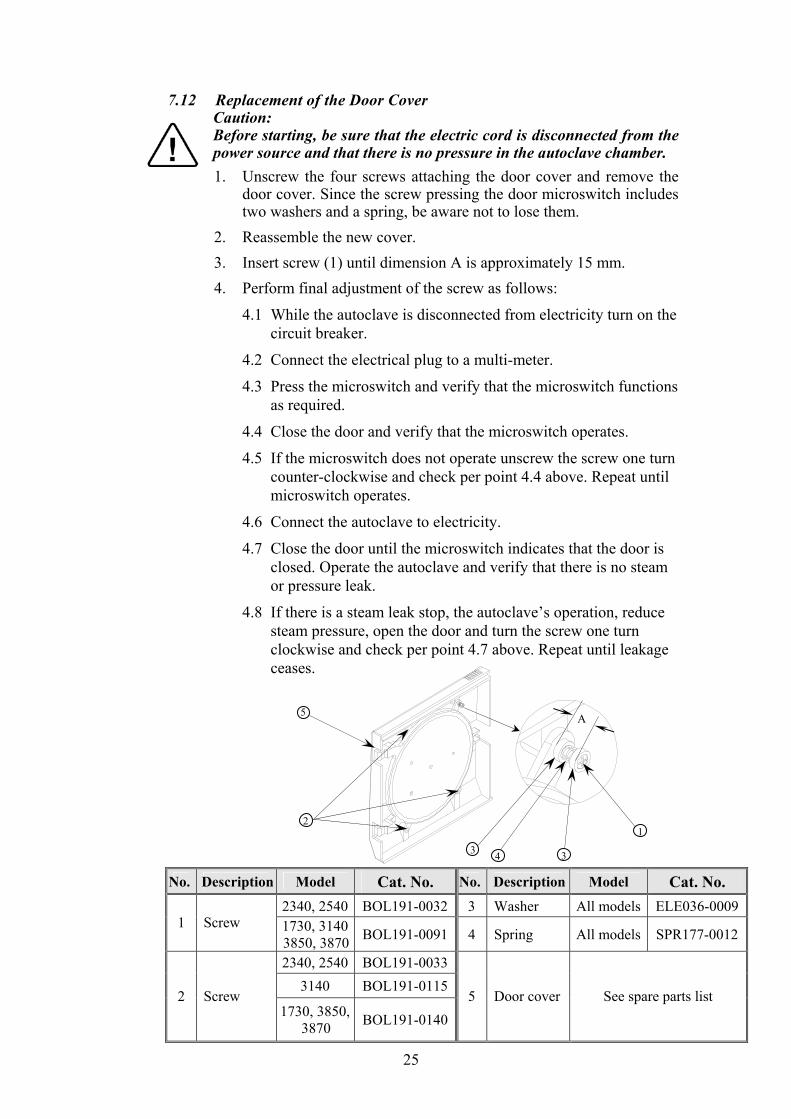
7.12 Replacement of the Door Cover Caution: Before starting, be sure that the electric cord is disconnected from the power source and that there is no pressure in the autoclave chamber.
1. Unscrew the four screws attaching the door cover and remove the door cover. Since the screw pressing the door microswitch includes two washers and a spring, be aware not to lose them.
2. Reassemble the new cover. 3. Insert screw (1) until dimension A is approximately 15 mm. 4. Perform final adjustment of the screw as follows:
4.1 While the autoclave is disconnected from electricity turn on the circuit breaker.
4.2 Connect the electrical plug to a multi-meter.
4.3 Press the microswitch and verify that the microswitch functions as required.
4.4 Close the door and verify that the microswitch operates.
4.5 If the microswitch does not operate unscrew the screw one turn counter-clockwise and check per point 4.4 above. Repeat until microswitch operates.
4.6 Connect the autoclave to electricity.
4.7 Close the door until the microswitch indicates that the door is closed. Operate the autoclave and verify that there is no steam or pressure leak.
4.8 If there is a steam leak stop, the autoclave’s operation, reduce steam pressure, open the door and turn the screw one turn clockwise and check per point 4.7 above. Repeat until leakage ceases.
No. Description Model Cat. No. No. Description Model Cat. No. 2340, 2540 BOL191-0032 3 Washer All models ELE036-0009
1 Screw 1730, 3140 3850, 3870 BOL191-0091 4 Spring All models SPR177-0012
2340, 2540 BOL191-00333140 BOL191-0115
2 Screw 1730, 3850,
3870 BOL191-01405 Door cover See spare parts list
4
1
3 3
A
2
5
26
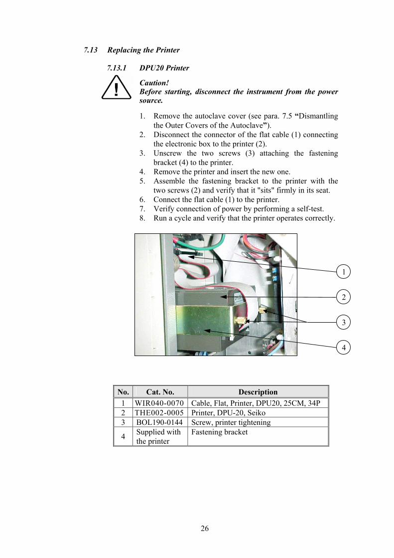
7.13 Replacing the Printer
7.13.1 DPU20 Printer
Caution! Before starting, disconnect the instrument from the power
source.
1. Remove the autoclave cover (see para. 7.5 “Dismantling the Outer Covers of the Autoclave”).
2. Disconnect the connector of the flat cable (1) connecting the electronic box to the printer (2).
3. Unscrew the two screws (3) attaching the fastening bracket (4) to the printer.
4. Remove the printer and insert the new one. 5. Assemble the fastening bracket to the printer with the
two screws (2) and verify that it "sits" firmly in its seat. 6. Connect the flat cable (1) to the printer. 7. Verify connection of power by performing a self-test. 8. Run a cycle and verify that the printer operates correctly.
1
3
2
4
No. Cat. No. Description 1 WIR040-0070 Cable, Flat, Printer, DPU20, 25CM, 34P 2 THE002-0005 Printer, DPU-20, Seiko 3 BOL190-0144 Screw, printer tightening
4 Supplied with the printer
Fastening bracket

27
7.13.2 DPU30 Printer
Caution! Before starting, disconnect the instrument from the power
source.
1. Remove the autoclave cover (see para. 7.5 “Dismantling the Outer Covers of the Autoclave”).
2. Disconnect the connector of the cable (1) connecting the electronic box to the printer (2).
3. Unscrew the two screws (3) attaching the fastening bracket (4) to the printer.
4. Remove the printer. 5. Set the dip switches on the new printer, located on the
back side of the printer, as follows:
6. Insert the new printer into its frame. 7. Assemble the fastening bracket to the printer with the
two screws (2) and verify that it is placed firmly. 8. Connect the (1) cable to the printer. 9. Verify connection of power by performing a self-test. 10. Run a cycle and verify that the printer operates correctly.
1
3
2
4
No. Cat. No. Description 1 CTP201-0127 Cable, Printer, DPU-30, 30cm, 34p 2 THE002-0022 Printer, DPU-30, Seiko 3 BOL190-0144 Screw, printer tightening
4 Supplied with the printer
Fastening bracket
5, 6, 7, 8 down
1, 2, 3, 4, up
9 up
10 down

28
7.14 Replacing the Door Switch
Caution! Before starting, disconnect the instrument from the power source and ensure that there is no pressure in the autoclave. Allow the autoclave to cool before removing outer covers. 1. Remove the autoclave cover (see para. 7.5 “Dismantling the Outer
Covers of the Autoclave”). 2. Disconnect wires (1), (2) from the door switch (3). 3. Remove the microswitch and replace it with a new one. 4. Reconnect the wires the microswitch. Verify that the wire is placed
on the isolating cover (4) and does not touch the chamber. 5. Reassemble the door cover. 6. Test the connection with an ohmmeter. In “open” position the
ohmmeter shows disconnection and in “close” position the ohmmeter shows connection.
3
2
1
4

29
7.15 Cleaning water inlet strainer Caution! Before proceeding, make sure that the electric cord is disconnected and there is no pressure in the autoclave.
1. Remove the cover of the autoclave. 2. Drain the water from the water reservoir. 3. Remove the water filter from the silicon tube. 4. Open the filter by unscrewing the two filter parts. 5. Clean the filter by flushing it under running water for a few
minutes. 6. Replace the filter parts and reconnect it to the silicon tube. 7. Open the water valve.
Water Reservoir Filter
30
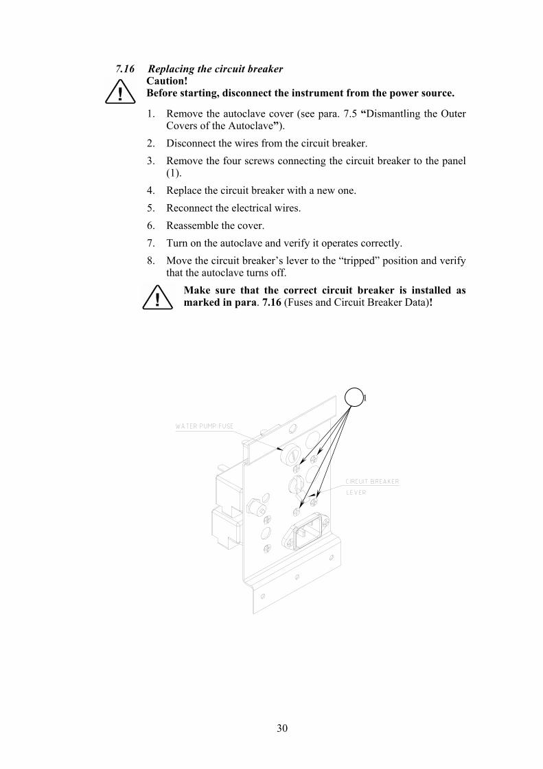
7.16 Replacing the circuit breaker Caution! Before starting, disconnect the instrument from the power source. 1. Remove the autoclave cover (see para. 7.5 “Dismantling the Outer
Covers of the Autoclave”). 2. Disconnect the wires from the circuit breaker. 3. Remove the four screws connecting the circuit breaker to the panel
(1). 4. Replace the circuit breaker with a new one. 5. Reconnect the electrical wires. 6. Reassemble the cover. 7. Turn on the autoclave and verify it operates correctly. 8. Move the circuit breaker’s lever to the “tripped” position and verify
that the autoclave turns off. Make sure that the correct circuit breaker is installed as marked in para. 7.16 (Fuses and Circuit Breaker Data)!
1

31
7.17 Fuses and Circuit Breaker Data
AUTOCLAVE TYPE E EA EK EKA DESCRIPTION
120V 230V 120V 230V 120V 230V 120V 230V
1730 Circuit breaker (A) 15 10 15 10
Air pump fuse (A)
Water pump fuse (A)
2340 / 2540 Circuit breaker (A) 15 10 15 10 15 15
Air pump fuse (A) 2.0 1.25 1.25
Water pump fuse (A) 1.25 1.25 1.25 1.25 1.25 1.25
3140 / 3850 / 3870 Circuit breaker (A) 15 15
Air pump fuse (A) 1.25
Water pump fuse (A) 1.25 1.25
3.11
.1.1
.1
L
For autoclavesModels EA, EKA
(with an air pump)
For autoclavesModels E, EK
(without an air pump)

32
7.18 Replacing the water pump
Caution! Before starting, disconnect the instrument from the power source.
1. Remove the autoclave cover (see para. 9.1 “Dismantling the Outer Covers of the Autoclave”).
2. Disconnect the wires from the pump 3. Empty the water reservoir. 4. Disconnect the piping from the pump. 5. Remove the pump from the rubber shock absorbers.
5.1 If the rubber shock absorbers are damaged, replace them. Note that on models 2340/2540 the shock absorber’s bases are pointed outward and on models 3140/3850/3870 they are pointed inward.
6. Replace the damaged pump with a new pump. 7. Reconnect wiring and piping. 8. Reassemble the cover. 9. Turn on the autoclave and verify it operates correctly.
No. Description 2340/2540 3140/3850/3870
1 Pump, Water, EXA7, 220V, Ulka PUM055-0014 PUM055-00142 Rubber shock absorber SKR203-0006 SKR203-0006
3 Hose adaptor, male, elbow, 1/8BSP, for 6 mm Hose. FIT100-0806 FIT100-0806
4 Screw BOL191-0140 BOL194-0342 5 Nut, Hex, Flange, 1/4NC NUT192-0155 6 washer NUT193-0347 NUT193-0276
7 Rivet, Dome Head, Aluminum, 4x14 BOL194-0331
2340/2540 3140/3850/3870
1 2
6
4
5
1
2
6
7
3
3

33
7.19 Replacing the Door Bellows (Located in the door bridge)
1. Open the door. 2. Unscrew and remove the tightening screw (5). 3. Gently pull out the door safety device locking pin (13). 4. It is possible that the washers (7, 10) will be stuck - if so, push them
out by introducing pressurized air through the steam inlet hole (8). No lubrication or cleaning is required. 5. Reconnect the door device locking pin (13) into a new silicone
bellows (12). 6. Put the silicone bellows (12) and pin (13) into the bellows housing
(14) and replace the washers (7,10). 7. Reconnect all the above into the door bridge. 8. Screw in the screws and tighten the tightening screw (5). 9. Test all the autoclave cycles.
LOK240-0026 LOK240-0025 LOK240-0023 GAS080-0020 LOK240-0024 GAS080-0006
34
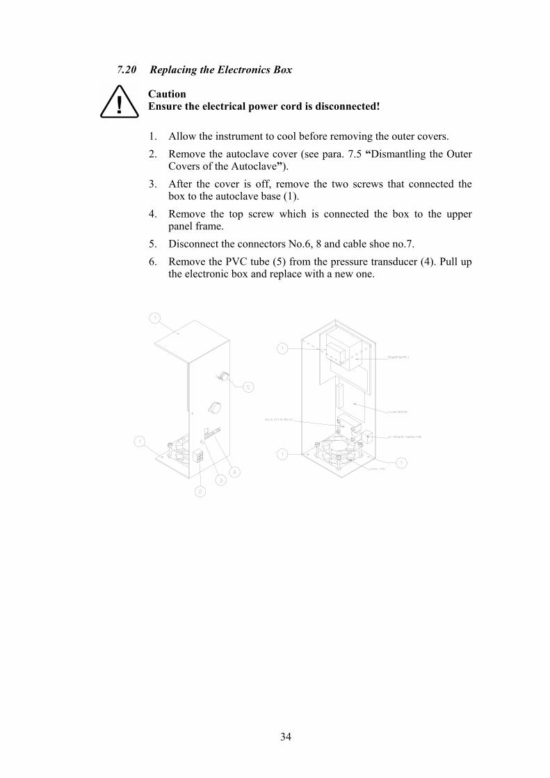
7.20 Replacing the Electronics Box Caution Ensure the electrical power cord is disconnected! 1. Allow the instrument to cool before removing the outer covers. 2. Remove the autoclave cover (see para. 7.5 “Dismantling the Outer
Covers of the Autoclave”). 3. After the cover is off, remove the two screws that connected the
box to the autoclave base (1). 4. Remove the top screw which is connected the box to the upper
panel frame. 5. Disconnect the connectors No.6, 8 and cable shoe no.7. 6. Remove the PVC tube (5) from the pressure transducer (4). Pull up
the electronic box and replace with a new one.

35
7.21 Validation Caution! Before starting the preparations for the validation, disconnect the instrument from the power source and ensure that there is no pressure in the autoclave.
The validation port is located on the autoclave's door, behind a plastic
plug inserted in the door cover.
1. Remove the plastic plug from the door cover. 2. Unscrew the validation plug from the door. 3. Attach the validation adapter to the validation port. The 1/4" BSP
thread of the validation port matches the thread of the adapter. 4. Perform the validation according to EN554 or the appropriate
Pharmacopea. 5. After completing the validation, reassemble the validation plug. Use
Teflon tape on the plug's thread to assure sealing. Tighten the plug carefully to avoid damage to the door.

36
8 DESCRIPTION AND FUNCTION OF DIP-SWITCHES The system allows certain changes of specific parameters:
1. Connection of an optional printer. 2. Change of parameters (temperature and time). 3. Setting autoclave identification, if there is more than one autoclave in
vicinity. 4. Stand by shoot mode. 5. Selecting between ºF,ºC, kPa, PSI. 6. Selection of dry cycle shoot mode for the quick or regular autoclave.
Changing the position of the DIP - SWITCH, as described below determines these parameters.
door Add water Fail Dry Exh. Ste. Heat
D2
JP2JP4 Keypad
PRINTER
ONOFF
1 2 3 4 5 6 7 8
D1
START
DIP SWITCH
PRINTERCONNECTOR
D3 4 D5 D6 D7 D8
37
8.1 Changing the parameters Not all the switches are relevant to this autoclave, details will be given
for the relevant switches only: Note: Changes must be done when the autoclave is shut off.
SWITCHES 1,2 Selecting an identification number for the autoclave 1 ON, 2 ON = number 1 1 ON, 2 OFF = number 2 1 OFF, 2 ON = number 3 1 OFF, 2 OFF = number 4 SWITCH 3 Change of parameters ON = Unable to change option OFF = Able to change option SWITCH 4 Stand by shoot mode ON = Able Off = Unable SWITCHES 5,6 Selection of temperature and pressure parameters 5 OFF, 6 OFF = °F ,psi 5 OFF, 6 ON = °F ,kPa 5 ON, 6 OFF = °C ,psi 5 ON, 6 ON = °C ,kPa SWITCH 7 Factory use only. SWITCH 8 Option for connecting a printer. ON printer is connecting. OFF printer not connected.
38
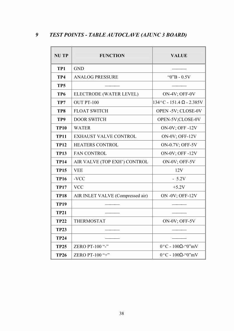
9 TEST POINTS - TABLE AUTOCLAVE (AJUNC 3 BOARD)
NU TP
FUNCTION
VALUE
TP1 GND
TP4 ANALOG PRESSURE “0”B - 0.5V
TP5
TP6 ELECTRODE (WATER LEVEL) ON-4V; OFF-0V
TP7 OUT PT-100 134ºC - 151.4 Ω - 2.385V
TP8 FLOAT SWITCH OPEN -5V; CLOSE-0V
TP9 DOOR SWITCH OPEN-5V;CLOSE-0V
TP10 WATER ON-0V; OFF -12V
TP11 EXHAUST VALVE CONTROL ON-0V; OFF-12V
TP12 HEATERS CONTROL ON-0.7V; OFF-5V
TP13 FAN CONTROL ON-0V; OFF -12V
TP14 AIR VALVE (TOP EXH’) CONTROL ON-0V; OFF-5V
TP15 VEE 12V
TP16 -VCC - 5.2V
TP17 VCC +5.2V
TP18 AIR INLET VALVE (Compressed air) ON -0V; OFF-12V
TP19
TP21
TP22 THERMOSTAT ON-0V; OFF-5V
TP23
TP24
TP25 ZERO PT-100 “-” 0ºC - 100Ω-“0”mV
TP26 ZERO PT-100 “+” 0ºC - 100Ω-“0”mV

39
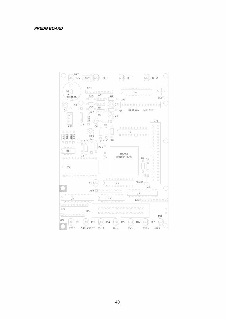
10 DETAILED DESCRIPTION OF ELECTRONIC SUB-ASSEMBLIES 10.1 PREDG board
1. U1 Micro-controller (MOTOROLA) comprises of the memory
(RAM and EPROM) A/D which is the central processing unit. 2. U2 Real time clock, contains the date and time of the day with a
100 years calendar, is the pilot clock of the system. It contains the back up memory for that data which must not be lost in case of a power failure.
The battery is good for ten years. It is recommended to replace U2 every 8 years.
3. The LCD display, is an alphanumeric display, with 16 characters on one line.
4. JP2, connector to the printer unit (SEIKO).. 5. JP1 connector to AJUNC3 BOARD. 6. U3, U4, integrated circuit 74H C373 having the function of latch -
drivers for the light signal LEDS, U7 and the valves controls. 7. U5, integrated circuits, has the function of buffer to the dip-switch. 8. U6, integrated circuit has the function of buffer to the keypad. 9. Transistors Q2 and Q7 are the control of the EXHAUST and
WATER valves, as well as of the FAN. 10. Temperature circuit is based on LM34AH, and the component U2. 11. There are also other components like capacitors, diodes and
resistors belonging to the battery back - up and crystal oscillator circuits.
See electrical schematic drawing for a more detailed view of the board.
40
PREDG BOARD
JP1
JP4D2 D3 D4 D5 D6 D7
D8
JP2RP1
RP3
RP3
U6 CRYS1
C1
C2
R1
U2
U5 DSW1
U3
D1
door Add water Fail Dry Exh. Ste. Heat
MICROCONTROLLER
U7
C3
R19
R4R11
C4
U8
R6R7R10
D13
JP3
Display 16417DY
U4
D9DRY
D10 D11 D12
RP4
R6
R9
Q2
Q5
R8Q6
D14R20
Q1
R14
R13
R12
R15
R18
R3
D17
D16
D15
Q7
Q4
Q3BUZZER
BZ1
+
-
ISO1
+ + + +
POT1

41
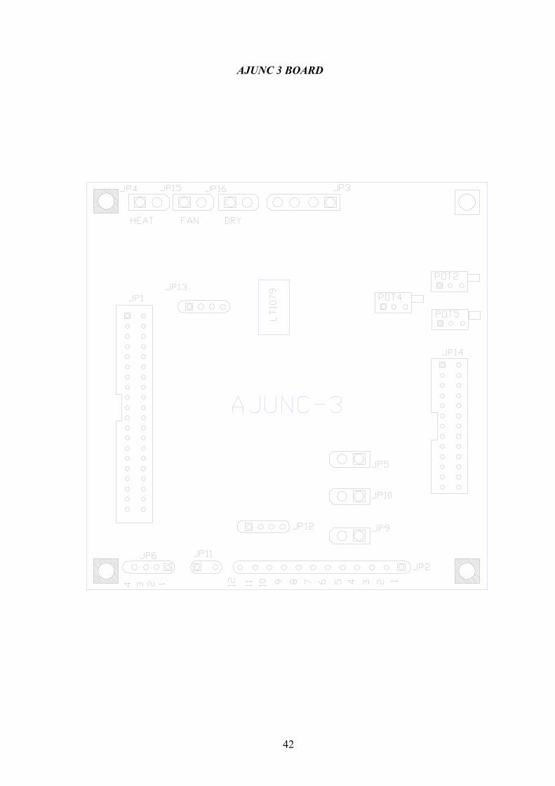
10.2 AJUNC 3 Board The AJUNC3 analog board is connected to the digital board, by a flat
cable, on connector JP1. This board contains all the analog and digital inputs required for the system. The board converts the analog input signal so the digital board can process it. In addition to this the board enables the microprocessor (on the digital board) to control all the digital outputs on the analog board.
The Board’s Connections and Functions:
JP1 Connection between the analog board and the digital board. JP2 Digital outputs for WATER, EXH, and AIR valves. Digital inputs for: thermostat, door switch, float switch and
analog input of the electrode. JP3 Power connection to the board: 5V & 12V. JP4 Control of the SSR controlling the heating elements. JP6 MPX2200AP pressure transducer input. JP10 Voltage output to the fan. JP11 PT100 temperature sensor input. JP12 Voltage output to DRY valve (EA, EKA only). JP13 Communication port JP14 Connection to TEST BOARD. JP15 Connection to drying-pump control (EA. EKA).
Potentiometers
By setting the potentiometers, the input signal is adjusted to the signal
required to be processed by the digital board.
POT1 Setting “Gain Pressure”. POT4 Setting “Zero Temp”. POT5 Seting “Gain Temp”.
42
AJUNC 3 BOARD
43
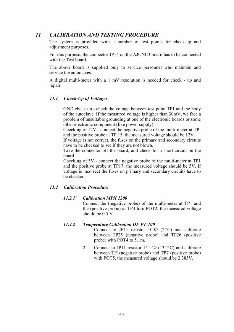
11 CALIBRATION AND TESTING PROCEDURE The system is provided with a number of test points for check-up and
adjustment purposes. For this purpose, the connector JP14 on the AJUNC3 board has to be connected
with the Test board. The above board is supplied only to service personnel who maintain and
service the autoclaves. A digital multi-meter with a 1 mV resolution is needed for check - up and
repair. 11.1 Check-Up of Voltages GND check up - check the voltage between test point TP1 and the body
of the autoclave. If the measured voltage is higher than 30mV, we face a problem of unsuitable grounding at one of the electronic boards or some other electronic component (like power supply).
Checking of 12V - connect the negative probe of the multi-meter at TPI and the positive probe at TP 15, the measured voltage should be 12V.
If voltage is not correct, the fuses on the primary and secondary circuits have to be checked to see if they are not blown.
Take the connector off the board, and check for a short-circuit on the board.
Checking of 5V - connect the negative probe of the multi-meter at TP1 and the positive probe at TP17, the measured voltage should be 5V. If voltage is incorrect the fuses on primary and secondary circuits have to be checked.
11.2 Calibration Procedure
11.2.1` Calibration MPX 2200 Connect the (negative probe) of the multi-meter at TP1 and
the (positive probe) at TP4 turn POT2, the measured voltage should be 0.5 V.
11.2.2 Temperature Calibration OF PT-100
1. Connect to JP11 resistor 100Ω (2ºC) and calibrate between TP25 (negative probe) and TP26 (positive probe) with POT4 to 5.1m.
2. Connect to JP11 resistor 151.4Ω (134ºC) and calibrate between TP1(negative probe) and TP7 (positive probe) with POT5, the measured voltage should be 2.385V.

44
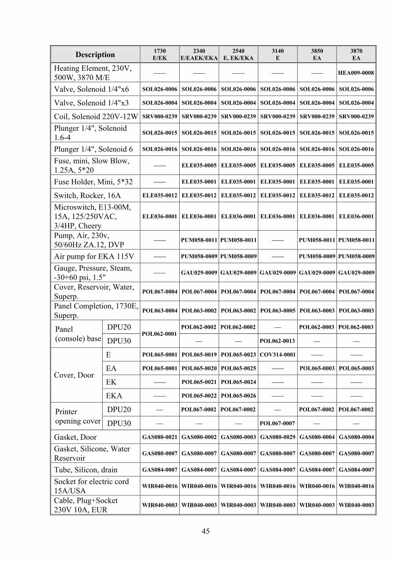
12 LIST OF SPARE PARTS
Description 1730 E/EK
2340 E/EAEK/EKA
2540 E, EK/EKA
3140 E
3850 EA
3870 EA
DPU 20 THE002-0005 THE002-0005 THE002-0005 THE002-0005Printer
DPU 30 THE002-0022
DPU 20 THE002-0003 THE002-0003 THE002-0003 THE002-0003Printer paper roll DPU 30 THE002-0025
Cable, Flat, Printer, DPU20, 25cm, 34P WIR040-0070 WIR040-0070 WIR040-0070 WIR040-0070
Cable, Printer, DPU-30, 30cm, 34p CTP201-0127
Sensor, Temperature, PT100, 3 Wires
ELC258-0003 ELC258-0003 ELC258-0003 ELC258-0003 ELC258-0003 ELC258-0003
Thermostat, Safety, 180C, TY95/AC, Campini
THE005-0003 THE005-0003 THE005-0003 THE005-0003 THE005-0003 THE005-0003
Thermostat, CUT-OFF, TY95-H, Campini
THE005-0014 THE005-0014 THE005-0014 THE005-0014 THE005-0014 THE005-0014
Transducer, Pressure, MPX 2200 AP
THE006-0003 THE006-0003 THE006-0003 THE006-0003 THE006-0003 THE006-0003
Switch, Float, Mini, Rico THE007-0001 THE007-0001 THE007-0001 THE007-0001 THE007-0001 THE007-0001
Heating Element, 120V, 350W 1730 M/E
HEA009-0001 —— —— —— —— ——
Heating Element, 120V, 350W 2340 M/E
—— HEA009-0002 —— —— —— ——
Heating Element, 120V, 350W 2540 M/E
—— —— HEA009-0003 —— —— ——
Heating Element, 230V, 350W, 1730 M/E
HEA009-0004 —— —— —— —— ——
Heating Element, 230V, 350W, 2340 M/E
—— HEA009-0005 —— —— —— ——
Heating Element, 230V, 350W, 2540 M/E
—— —— HEA009-0006 —— —— ——
Heating Element, 120V, 450W, 1730 MK/EK
HEA010-0007 —— —— —— —— ——
Heating Element, 230V, 450W, 1730 MK/EK
HEA010-0008 —— —— —— —— ——
Heating Element, 230V, 550W, 2340 MK/EK
—— HEA010-0003 —— —— —— ——
Heating Element, 230V, 550W, 2540 MK/EK
—— —— HEA010-0004 —— —— ——
Heating Element 230V 600W 3140 M/E
—— —— —— HEA009-0014 —— ——
Heating Element, 230V, 600W, 3850 M/E
—— —— —— —— HEA009-0007 ——
Heating Element, 240V, 600W, 3870 M/E
—— —— —— —— HEA009-0013 ——
45
Description 1730 E/EK
2340 E/EAEK/EKA
2540 E, EK/EKA
3140 E
3850 EA
3870 EA
Heating Element, 230V, 500W, 3870 M/E
—— —— —— —— —— HEA009-0008
Valve, Solenoid 1/4"x6 SOL026-0006 SOL026-0006 SOL026-0006 SOL026-0006 SOL026-0006 SOL026-0006
Valve, Solenoid 1/4"x3 SOL026-0004 SOL026-0004 SOL026-0004 SOL026-0004 SOL026-0004 SOL026-0004
Coil, Solenoid 220V-12W SRV000-0239 SRV000-0239 SRV000-0239 SRV000-0239 SRV000-0239 SRV000-0239
Plunger 1/4", Solenoid 1.6-4
SOL026-0015 SOL026-0015 SOL026-0015 SOL026-0015 SOL026-0015 SOL026-0015
Plunger 1/4", Solenoid 6 SOL026-0016 SOL026-0016 SOL026-0016 SOL026-0016 SOL026-0016 SOL026-0016
Fuse, mini, Slow Blow, 1.25A, 5*20
—— ELE035-0005 ELE035-0005 ELE035-0005 ELE035-0005 ELE035-0005
Fuse Holder, Mini, 5*32 —— ELE035-0001 ELE035-0001 ELE035-0001 ELE035-0001 ELE035-0001
Switch, Rocker, 16A ELE035-0012 ELE035-0012 ELE035-0012 ELE035-0012 ELE035-0012 ELE035-0012
Microswitch, E13-00M, 15A, 125/250VAC, 3/4HP, Cheery
ELE036-0001 ELE036-0001 ELE036-0001 ELE036-0001 ELE036-0001 ELE036-0001
Pump, Air, 230v, 50/60Hz ZA.12, DVP
—— PUM058-0011 PUM058-0011 —— PUM058-0011 PUM058-0011
Air pump for EKA 115V —— PUM058-0009 PUM058-0009 —— PUM058-0009 PUM058-0009
Gauge, Pressure, Steam, -30+60 psi, 1.5"
—— GAU029-0009 GAU029-0009 GAU029-0009 GAU029-0009 GAU029-0009
Cover, Reservoir, Water, Superp.
POL067-0004 POL067-0004 POL067-0004 POL067-0004 POL067-0004 POL067-0004
Panel Completion, 1730E, Superp.
POL063-0004 POL063-0002 POL063-0002 POL063-0005 POL063-0003 POL063-0003
DPU20 POL062-0002 POL062-0002 POL062-0003 POL062-0003Panel (console) base DPU30
POL062-0001 POL062-0013
E POL065-0001 POL065-0019 POL065-0023 COV314-0001 —— ——
EA POL065-0001 POL065-0020 POL065-0025 —— POL065-0003 POL065-0003
EK —— POL065-0021 POL065-0024 —— —— —— Cover, Door
EKA —— POL065-0022 POL065-0026 —— —— ——
DPU20 POL067-0002 POL067-0002 POL067-0002 POL067-0002Printer opening cover DPU30 POL067-0007
Gasket, Door GAS080-0021 GAS080-0002 GAS080-0003 GAS080-0029 GAS080-0004 GAS080-0004
Gasket, Silicone, Water Reservoir
GAS080-0007 GAS080-0007 GAS080-0007 GAS080-0007 GAS080-0007 GAS080-0007
Tube, Silicon, drain GAS084-0007 GAS084-0007 GAS084-0007 GAS084-0007 GAS084-0007 GAS084-0007
Socket for electric cord 15A/USA
WIR040-0016 WIR040-0016 WIR040-0016 WIR040-0016 WIR040-0016 WIR040-0016
Cable, Plug+Socket 230V 10A, EUR
WIR040-0003 WIR040-0003 WIR040-0003 WIR040-0003 WIR040-0003 WIR040-0003
46
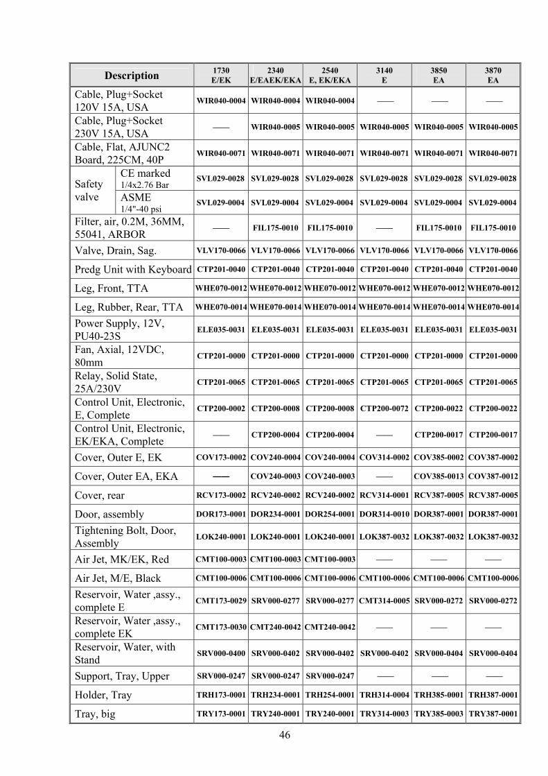
Description 1730 E/EK
2340 E/EAEK/EKA
2540 E, EK/EKA
3140 E
3850 EA
3870 EA
Cable, Plug+Socket 120V 15A, USA
WIR040-0004 WIR040-0004 WIR040-0004 —— —— ——
Cable, Plug+Socket 230V 15A, USA
—— WIR040-0005 WIR040-0005 WIR040-0005 WIR040-0005 WIR040-0005
Cable, Flat, AJUNC2 Board, 225CM, 40P
WIR040-0071 WIR040-0071 WIR040-0071 WIR040-0071 WIR040-0071 WIR040-0071
CE marked 1/4x2.76 Bar SVL029-0028 SVL029-0028 SVL029-0028 SVL029-0028 SVL029-0028 SVL029-0028Safety
valve ASME 1/4"-40 psi SVL029-0004 SVL029-0004 SVL029-0004 SVL029-0004 SVL029-0004 SVL029-0004
Filter, air, 0.2M, 36MM, 55041, ARBOR
—— FIL175-0010 FIL175-0010 —— FIL175-0010 FIL175-0010
Valve, Drain, Sag. VLV170-0066 VLV170-0066 VLV170-0066 VLV170-0066 VLV170-0066 VLV170-0066
Predg Unit with Keyboard CTP201-0040 CTP201-0040 CTP201-0040 CTP201-0040 CTP201-0040 CTP201-0040
Leg, Front, TTA WHE070-0012 WHE070-0012 WHE070-0012 WHE070-0012 WHE070-0012 WHE070-0012
Leg, Rubber, Rear, TTA WHE070-0014 WHE070-0014 WHE070-0014 WHE070-0014 WHE070-0014 WHE070-0014
Power Supply, 12V, PU40-23S
ELE035-0031 ELE035-0031 ELE035-0031 ELE035-0031 ELE035-0031 ELE035-0031
Fan, Axial, 12VDC, 80mm
CTP201-0000 CTP201-0000 CTP201-0000 CTP201-0000 CTP201-0000 CTP201-0000
Relay, Solid State, 25A/230V
CTP201-0065 CTP201-0065 CTP201-0065 CTP201-0065 CTP201-0065 CTP201-0065
Control Unit, Electronic, E, Complete
CTP200-0002 CTP200-0008 CTP200-0008 CTP200-0072 CTP200-0022 CTP200-0022
Control Unit, Electronic, EK/EKA, Complete
—— CTP200-0004 CTP200-0004 —— CTP200-0017 CTP200-0017
Cover, Outer E, EK COV173-0002 COV240-0004 COV240-0004 COV314-0002 COV385-0002 COV387-0002
Cover, Outer EA, EKA —— COV240-0003 COV240-0003 —— COV385-0013 COV387-0012
Cover, rear RCV173-0002 RCV240-0002 RCV240-0002 RCV314-0001 RCV387-0005 RCV387-0005
Door, assembly DOR173-0001 DOR234-0001 DOR254-0001 DOR314-0010 DOR387-0001 DOR387-0001
Tightening Bolt, Door, Assembly
LOK240-0001 LOK240-0001 LOK240-0001 LOK387-0032 LOK387-0032 LOK387-0032
Air Jet, MK/EK, Red CMT100-0003 CMT100-0003 CMT100-0003 —— —— ——
Air Jet, M/E, Black CMT100-0006 CMT100-0006 CMT100-0006 CMT100-0006 CMT100-0006 CMT100-0006
Reservoir, Water ,assy., complete E
CMT173-0029 SRV000-0277 SRV000-0277 CMT314-0005 SRV000-0272 SRV000-0272
Reservoir, Water ,assy., complete EK
CMT173-0030 CMT240-0042 CMT240-0042 —— —— ——
Reservoir, Water, with Stand
SRV000-0400 SRV000-0402 SRV000-0402 SRV000-0402 SRV000-0404 SRV000-0404
Support, Tray, Upper SRV000-0247 SRV000-0247 SRV000-0247 —— —— ——
Holder, Tray TRH173-0001 TRH234-0001 TRH254-0001 TRH314-0004 TRH385-0001 TRH387-0001
Tray, big TRY173-0001 TRY240-0001 TRY240-0001 TRY314-0003 TRY385-0003 TRY387-0001

47
Description 1730 E/EK
2340 E/EAEK/EKA
2540 E, EK/EKA
3140 E
3850 EA
3870 EA
Tray, small —— —— —— TRY314-0004 TRY385-0004 TRY387-0003
Handle, Tray, CMT240-0001 CMT240-0001 CMT240-0001 —— —— ——
Bellows, Door Lock GAS080-0020 GAS080-0020 GAS080-0020 GAS080-0020 GAS080-0020 GAS080-0020
Tightening Bolt, Door Locking Bellows
LOK240-0026 LOK240-0026 LOK240-0026 LOK240-0026 LOK240-0026 LOK240-0026
Housing, Door Locking Bellows
LOK240-0025 LOK240-0025 LOK240-0025 LOK240-0025 LOK240-0025 LOK240-0025
Pin, Membrane L0K240-0023 L0K240-0023 L0K240-0023 L0K240-0023 L0K240-0023 L0K240-0023
Bushing, Inner, bellows CMT067-0002 CMT067-0002 CMT067-0002 CMT067-0002 CMT067-0002 CMT067-0002
Disc, Silicone, Door Bellows
GAS080-0006 GAS080-0006 GAS080-0006 GAS080-0006 GAS080-0006 GAS080-0006
O-Ring, 10 x 2.5, Viton GAS082-0020 GAS082-0020 GAS082-0020 GAS082-0020 GAS082-0020 GAS082-0020
O-Ring, 6 x 2, Viton GAS082-0021 GAS082-0021 GAS082-0021 GAS082-0021 GAS082-0021 GAS082-0021
Electrode, Water Level, Assembly, For TTA
CMT196-0004 CMT196-0004 CMT196-0004 CMT196-0004 CMT196-0004 CMT196-0004
Dipstick, Reservoir, Water, Superp.
POL067-0005 POL067-0005 POL067-0005 POL067-0005 POL067-0005 POL067-0005
Cap, water strainer, ¼” FIL175-0027 FIL175-0027 FIL175-0027 FIL175-0027 FIL175-0027 FIL175-0027
Screen, 400 Micron, For Strainer 1/4"
FIL175-0046 FIL175-0046 FIL175-0046 FIL175-0046 FIL175-0046 FIL175-0046
Gasket, 3mm, Silicon, for 1/4" Strainer
GAS082-0007 GAS082-0007 GAS082-0007 —— —— ——
Gasket, 4mm, Silicon, for 1/4" Strainer
—— —— —— GAS082-0008 GAS082-0008 GAS082-0008
Strainer, Water, Housing + cap, 1/4
FIL175-0051 FIL175-0051 FIL175-0051 FIL175-0051 FIL175-0051 FIL175-0051
Circuit Breaker, Rail, 1PH, 10A, Carlingswitch
ELE035-0019 ELE035-0019 ELE035-0019 ELE035-0019 ELE035-0019 ELE035-0019
Circuit Breaker, Rail, 1PH, 15A, Carlingswitch
ELE035-0021 ELE035-0021 ELE035-0021 ELE035-0021 ELE035-0021 ELE035-0021
Cover, Door POL065-0001 POL065-0002 POL065-0002 COV314-0001 POL065-0003 POL065-0003
Cover, Validation Port —— POL065-0006 POL065-0006 POL065-0006 POL065-0006 POL065-0006
Cover, RS232 Opening, Superp.
POL067-0003 POL067-0003 POL067-0003 POL067-0003 POL067-0003 POL067-0003
Capacitor, 470nF CTP201-0016 CTP201-0016 CTP201-0016 CTP201-0016 CTP201-0016 CTP201-0016

48
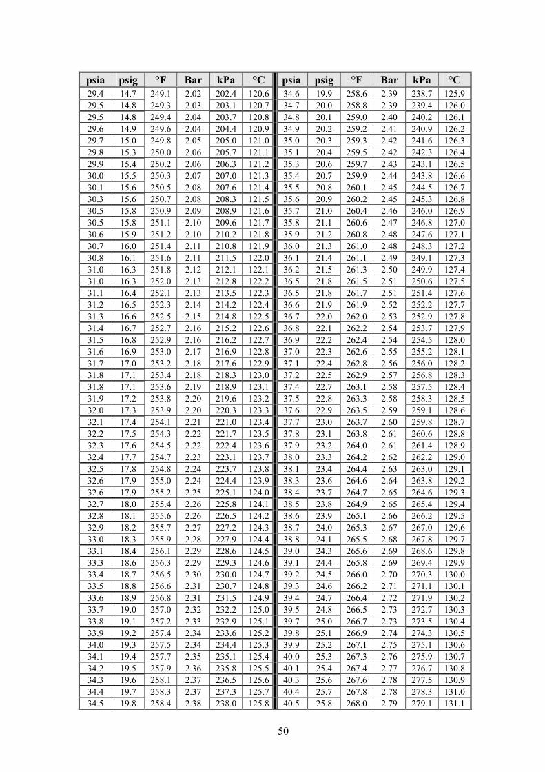
13 PRESSURE VS TEMPERATURE FOR SATURATED STEAM °C kPa Bar °F psig psia °C kPa Bar °F psig psia
104.9120.4 1.20 220.8 2.8 17.5 100.0101.3 1.01 212.0 0.0 14.7 105.0120.7 1.21 221.0 2.8 17.5 100.1101.7 1.02 212.2 0.1 14.8 105.1121.3 1.21 221.2 2.9 17.6 100.2102.1 1.02 212.4 0.1 14.8 105.2122.0 1.22 221.4 3.0 17.7 100.3102.4 1.02 212.5 0.2 14.9 105.3122.0 1.22 221.5 3.0 17.7 100.4102.8 1.03 212.7 0.2 14.9 105.4122.7 1.23 221.7 3.1 17.8 100.5103.2 1.03 212.9 0.3 15.0 105.5122.7 1.23 221.9 3.1 17.8 100.6103.6 1.04 213.1 0.3 15.0 105.6123.4 1.23 222.1 3.2 17.9 100.7104.0 1.04 213.3 0.4 15.1 105.7124.1 1.24 222.3 3.3 18.0 100.8104.3 1.04 213.4 0.4 15.1 105.8124.1 1.24 222.4 3.3 18.0 100.9104.7 1.05 213.6 0.5 15.2 105.9124.7 1.24 222.6 3.4 18.1 101.0105.1 1.05 213.8 0.5 15.2 106.0125.1 1.25 222.8 3.5 18.2 101.1105.4 1.05 214.0 0.6 15.3 106.1125.5 1.26 223.0 3.5 18.2 101.2105.8 1.06 214.2 0.7 15.4 106.2126.0 1.26 223.2 3.6 18.3 101.3106.2 1.06 214.3 0.7 15.4 106.3126.2 1.26 223.3 3.6 18.3 101.4106.6 1.07 214.5 0.8 15.5 106.4126.8 1.27 223.5 3.7 18.4 101.5106.9 1.07 214.7 0.8 15.5 106.5127.2 1.27 223.7 3.8 18.5 101.6107.3 1.07 214.9 0.9 15.6 106.6127.7 1.28 223.9 3.8 18.5 101.7107.7 1.08 215.1 0.9 15.6 106.7128.1 1.28 224.1 3.9 18.6 101.8108.1 1.08 215.2 1.0 15.7 106.8128.5 1.29 224.2 3.9 18.6 101.9108.4 1.08 215.4 1.0 15.7 106.9129.0 1.29 224.4 4.0 18.7 102.0108.8 1.09 215.6 1.1 15.8 107.0129.6 1.29 224.6 4.1 18.8 102.1109.2 1.09 215.8 1.1 15.8 107.1129.9 1.30 224.8 4.2 18.9 102.2109.6 1.10 216.0 1.2 15.9 107.2130.4 1.30 225.0 4.2 18.9 102.4110.0 1.10 216.3 1.3 16.0 107.3130.8 1.31 225.1 4.3 19.0 102.5110.7 1.11 216.5 1.4 16.1 107.4131.3 1.31 225.3 4.3 19.0 102.6111.1 1.11 216.7 1.4 16.1 107.5131.7 1.32 225.5 4.4 19.1 102.7111.5 1.12 216.9 1.5 16.2 107.6132.2 1.32 225.7 4.5 19.2 102.8111.9 1.12 217.0 1.5 16.2 107.7132.6 1.33 225.9 4.6 19.3 102.9112.3 1.12 217.2 1.6 16.3 107.8133.1 1.33 226.0 4.6 19.3 103.0112.7 1.13 217.4 1.7 16.4 107.9133.5 1.34 226.2 4.7 19.4 103.1113.1 1.13 217.6 1.7 16.4 108.0134.0 1.34 226.4 4.7 19.4 103.2113.5 1.14 217.8 1.8 16.5 108.1134.4 1.34 226.6 4.8 19.5 103.3114.0 1.14 217.9 1.8 16.5 108.2134.9 1.35 226.8 4.9 19.6 103.4114.3 1.14 218.1 1.9 16.6 108.3135.3 1.35 226.9 4.9 19.6 103.5114.7 1.15 218.3 1.9 16.6 108.4135.8 1.36 227.1 5.0 19.7 103.6115.1 1.15 218.5 2.0 16.7 108.5136.2 1.36 227.3 5.1 19.8 103.7115.6 1.16 218.7 2.1 16.8 108.6136.7 1.37 227.5 5.1 19.8 103.8116.0 1.16 218.8 2.1 16.8 108.7137.1 1.37 227.7 5.2 19.9 103.9116.3 1.16 219.0 2.2 16.9 108.8137.6 1.38 227.8 5.2 19.9 104.0116.7 1.17 219.2 2.2 16.9 108.9138.1 1.38 228.0 5.3 20.0 104.1117.1 1.17 219.4 2.3 17.0 109.0138.5 1.39 228.2 5.4 20.1 104.2117.5 1.18 219.6 2.4 17.1 109.1139.0 1.39 228.4 5.5 20.2 104.3117.9 1.18 219.7 2.4 17.1 109.2139.5 1.39 228.6 5.6 20.3 104.4118.6 1.18 219.9 2.5 17.2 109.3140.0 1.40 228.7 5.6 20.3 104.5118.6 1.19 220.1 2.5 17.2 109.4140.5 1.40 228.9 5.7 20.4 104.6119.3 1.19 220.3 2.6 17.3 109.5140.9 1.41 229.1 5.7 20.4 104.7120.0 1.20 220.5 2.7 17.4
104.8120.0 1.20 220.6 2.7 17.4

49
°C kPa Bar °F psig psia °C kPa Bar °F psig psia 115.1 169.7 1.70 239.2 9.9 24.6 109.6141.4 1.41 229.3 5.8 20.5 115.2 170.2 1.70 239.4 10.0 24.7 109.7142.0 1.42 229.5 5.9 20.6 115.3 170.8 1.71 239.5 10.0 24.7 109.8142.4 1.42 229.6 5.9 20.6 115.4 171.3 1.71 239.7 10.1 24.8 109.9142.9 1.43 229.8 6.0 20.7 115.5 171.8 1.72 239.9 10.2 24.9 110.0143.3 1.43 230.0 6.1 20.8 115.6 172.4 1.72 240.1 10.3 25.0 110.1143.9 1.44 230.2 6.2 20.9 115.7 173.1 1.73 240.3 10.4 25.1 110.2144.3 1.44 230.4 6.3 21.0 115.8 173.6 1.74 240.4 10.5 25.2 110.3144.8 1.45 230.5 6.3 21.0 115.9 174.1 1.74 240.6 10.6 25.3 110.4145.3 1.45 230.7 6.4 21.1 116.0 174.7 1.75 240.8 10.6 25.3 110.5145.8 1.46 230.9 6.4 21.1 116.1 175.3 1.75 241.0 10.7 25.4 110.6146.2 1.46 231.1 6.5 21.2 116.2 175.9 1.76 241.2 10.8 25.5 110.7146.7 1.47 231.3 6.6 21.3 116.3 176.4 1.76 241.3 10.9 25.6 110.8147.2 1.47 231.4 6.6 21.3 116.4 177.0 1.77 241.5 11.0 25.7 110.9147.7 1.48 231.6 6.7 21.4 116.5 177.6 1.78 241.7 11.1 25.8 111.0148.2 1.48 231.8 6.8 21.5 116.6 178.2 1.78 241.9 11.2 25.9 111.1148.6 1.49 232.0 6.9 21.6 116.7 178.7 1.79 242.1 11.2 25.9 111.2149.6 1.49 232.2 7.0 21.7 116.8 179.3 1.79 242.2 11.3 26.0 111.3149.6 1.50 232.3 7.0 21.7 116.9 180.0 1.80 242.4 11.4 26.1 111.4150.3 1.50 232.5 7.1 21.8 117.0 180.5 1.80 242.6 11.5 26.2 111.5151.0 1.51 232.7 7.2 21.9 117.1 181.1 1.81 242.8 11.6 26.3 111.6151.0 1.51 232.9 7.2 21.9 117.2 181.6 1.82 243.0 11.7 26.4 111.7151.7 1.52 233.1 7.3 22.0 117.3 182.2 1.82 243.1 11.7 26.4 111.8152.2 1.52 233.2 7.4 22.1 117.4 182.8 1.83 243.3 11.8 26.5 111.9152.7 1.53 233.4 7.4 22.1 117.5 183.4 1.83 243.5 11.9 26.6 112.0153.2 1.53 233.6 7.5 22.2 117.6 184.0 1.84 243.7 12.0 26.7 112.1153.8 1.54 233.8 7.6 22.3 117.7 184.5 1.85 243.9 12.1 26.8 112.2154.3 1.54 234.0 7.7 22.4 117.8 185.1 1.85 244.0 12.1 26.8 112.3154.8 1.55 234.1 7.7 22.4 117.9 185.7 1.86 244.2 12.2 26.9 112.4155.3 1.55 234.3 7.8 22.5 118.0 186.3 1.86 244.4 12.3 27.0 112.5155.8 1.56 234.5 7.9 22.6 118.1 186.9 1.87 244.6 12.4 27.1 112.6156.3 1.56 234.7 8.0 22.7 118.2 187.5 1.88 244.8 12.5 27.2 112.7156.8 1.57 234.9 8.1 22.8 118.3 188.2 1.88 244.9 12.6 27.3 112.8157.3 1.57 235.0 8.1 22.8 118.4 188.8 1.89 245.1 12.7 27.4 112.9157.9 1.58 235.2 8.2 22.9 118.5 189.4 1.89 245.3 12.8 27.5 113.0158.4 1.58 235.4 8.3 23.0 118.6 190.0 1.90 245.5 12.9 27.6 113.1158.9 1.59 235.6 8.4 23.1 118.7 190.6 1.91 245.7 13.0 27.7 113.2159.4 1.59 235.8 8.4 23.1 118.8 191.2 1.91 245.8 13.0 27.7 113.3159.9 1.60 235.9 8.5 23.2 118.9 191.8 1.92 246.0 13.1 27.8 113.4160.4 1.60 236.1 8.6 23.3 119.0 192.4 1.92 246.2 13.2 27.9 113.5160.0 1.61 236.3 8.7 23.4 119.1 193.0 1.93 246.4 13.3 28.0 113.6161.5 1.62 236.5 8.7 23.4 119.2 193.7 1.94 246.6 13.4 28.1 113.7162.1 1.62 236.7 8.8 23.5 119.3 194.3 1.94 246.7 13.5 28.2 113.8162.6 1.63 236.8 8.9 23.6 119.4 194.9 1.95 246.9 13.6 28.3 113.9163.1 1.63 237.0 9.0 23.7 119.5 195.5 1.95 247.1 13.7 28.4 114.0163.7 1.64 237.2 9.0 23.7 119.6 196.1 1.96 247.3 13.8 28.5 114.1164.2 1.64 237.4 9.1 23.8 119.7 196.7 1.97 247.5 13.9 28.6 114.2164.8 1.65 237.6 9.2 23.9 119.8 197.3 1.97 247.6 13.9 28.6 114.3165.3 1.65 237.7 9.3 24.0 119.9 197.9 1.98 247.8 14.0 28.7 114.4165.9 1.66 237.9 9.4 24.1 120.0 198.5 1.99 248.0 14.1 28.8 114.5166.4 1.66 238.1 9.4 24.1 120.1 199.2 1.99 248.2 14.2 28.9 114.6167.0 1.67 238.3 9.5 24.2 120.2 199.8 2.00 248.4 14.3 29.0 114.7167.5 1.67 238.5 9.6 24.3 120.3 200.5 2.00 248.5 14.4 29.1 114.8168.0 1.68 238.6 9.7 24.4 120.4 201.1 2.01 248.7 14.5 29.2 114.9168.6 1.69 238.8 9.7 24.4 120.5 201.8 2.02 248.9 14.6 29.3 115.0169.1 1.69 239.0 9.8 24.5
50
°C kPa Bar °F psig psia °C kPa Bar °F psig psia 125.9 238.7 2.39 258.6 19.9 34.6 120.6202.4 2.02 249.1 14.7 29.4 126.0 239.4 2.39 258.8 20.0 34.7 120.7203.1 2.03 249.3 14.8 29.5 126.1 240.2 2.40 259.0 20.1 34.8 120.8203.7 2.04 249.4 14.8 29.5 126.2 240.9 2.41 259.2 20.2 34.9 120.9204.4 2.04 249.6 14.9 29.6 126.3 241.6 2.42 259.3 20.3 35.0 121.0205.0 2.05 249.8 15.0 29.7 126.4 242.3 2.42 259.5 20.4 35.1 121.1205.7 2.06 250.0 15.3 29.8 126.5 243.1 2.43 259.7 20.6 35.3 121.2206.3 2.06 250.2 15.4 29.9 126.6 243.8 2.44 259.9 20.7 35.4 121.3207.0 2.07 250.3 15.5 30.0 126.7 244.5 2.45 260.1 20.8 35.5 121.4207.6 2.08 250.5 15.6 30.1 126.8 245.3 2.45 260.2 20.9 35.6 121.5208.3 2.08 250.7 15.6 30.3 126.9 246.0 2.46 260.4 21.0 35.7 121.6208.9 2.09 250.9 15.8 30.5 127.0 246.8 2.47 260.6 21.1 35.8 121.7209.6 2.10 251.1 15.8 30.5 127.1 247.6 2.48 260.8 21.2 35.9 121.8210.2 2.10 251.2 15.9 30.6 127.2 248.3 2.48 261.0 21.3 36.0 121.9210.8 2.11 251.4 16.0 30.7 127.3 249.1 2.49 261.1 21.4 36.1 122.0211.5 2.11 251.6 16.1 30.8 127.4 249.9 2.50 261.3 21.5 36.2 122.1212.1 2.12 251.8 16.3 31.0 127.5 250.6 2.51 261.5 21.8 36.5 122.2212.8 2.13 252.0 16.3 31.0 127.6 251.4 2.51 261.7 21.8 36.5 122.3213.5 2.13 252.1 16.4 31.1 127.7 252.2 2.52 261.9 21.9 36.6 122.4214.2 2.14 252.3 16.5 31.2 127.8 252.9 2.53 262.0 22.0 36.7 122.5214.8 2.15 252.5 16.6 31.3 127.9 253.7 2.54 262.2 22.1 36.8 122.6215.2 2.16 252.7 16.7 31.4 128.0 254.5 2.54 262.4 22.2 36.9 122.7216.2 2.16 252.9 16.8 31.5 128.1 255.2 2.55 262.6 22.3 37.0 122.8216.9 2.17 253.0 16.9 31.6 128.2 256.0 2.56 262.8 22.4 37.1 122.9217.6 2.18 253.2 17.0 31.7 128.3 256.8 2.57 262.9 22.5 37.2 123.0218.3 2.18 253.4 17.1 31.8 128.4 257.5 2.58 263.1 22.7 37.4 123.1218.9 2.19 253.6 17.1 31.8 128.5 258.3 2.58 263.3 22.8 37.5 123.2219.6 2.20 253.8 17.2 31.9 128.6 259.1 2.59 263.5 22.9 37.6 123.3220.3 2.20 253.9 17.3 32.0 128.7 259.8 2.60 263.7 23.0 37.7 123.4221.0 2.21 254.1 17.4 32.1 128.8 260.6 2.61 263.8 23.1 37.8 123.5221.7 2.22 254.3 17.5 32.2 128.9 261.4 2.61 264.0 23.2 37.9 123.6222.4 2.22 254.5 17.6 32.3 129.0 262.2 2.62 264.2 23.3 38.0 123.7223.1 2.23 254.7 17.7 32.4 129.1 263.0 2.63 264.4 23.4 38.1 123.8223.7 2.24 254.8 17.8 32.5 129.2 263.8 2.64 264.6 23.6 38.3 123.9224.4 2.24 255.0 17.9 32.6 129.3 264.6 2.65 264.7 23.7 38.4 124.0225.1 2.25 255.2 17.9 32.6 129.4 265.4 2.65 264.9 23.8 38.5 124.1225.8 2.26 255.4 18.0 32.7 129.5 266.2 2.66 265.1 23.9 38.6 124.2226.5 2.26 255.6 18.1 32.8 129.6 267.0 2.67 265.3 24.0 38.7 124.3227.2 2.27 255.7 18.2 32.9 129.7 267.8 2.68 265.5 24.1 38.8 124.4227.9 2.28 255.9 18.3 33.0 129.8 268.6 2.69 265.6 24.3 39.0 124.5228.6 2.29 256.1 18.4 33.1 129.9 269.4 2.69 265.8 24.4 39.1 124.6229.3 2.29 256.3 18.6 33.3 130.0 270.3 2.70 266.0 24.5 39.2 124.7230.0 2.30 256.5 18.7 33.4 130.1 271.1 2.71 266.2 24.6 39.3 124.8230.7 2.31 256.6 18.8 33.5 130.2 271.9 2.72 266.4 24.7 39.4 124.9231.5 2.31 256.8 18.9 33.6 130.3 272.7 2.73 266.5 24.8 39.5 125.0232.2 2.32 257.0 19.0 33.7 130.4 273.5 2.73 266.7 25.0 39.7 125.1232.9 2.33 257.2 19.1 33.8 130.5 274.3 2.74 266.9 25.1 39.8 125.2233.6 2.34 257.4 19.2 33.9 130.6 275.1 2.75 267.1 25.2 39.9 125.3234.4 2.34 257.5 19.3 34.0 130.7 275.9 2.76 267.3 25.3 40.0 125.4235.1 2.35 257.7 19.4 34.1 130.8 276.7 2.77 267.4 25.4 40.1 125.5235.8 2.36 257.9 19.5 34.2 130.9 277.5 2.78 267.6 25.6 40.3 125.6236.5 2.37 258.1 19.6 34.3 131.0 278.3 2.78 267.8 25.7 40.4 125.7237.3 2.37 258.3 19.7 34.4 131.1 279.1 2.79 268.0 25.8 40.5 125.8238.0 2.38 258.4 19.8 34.5
51
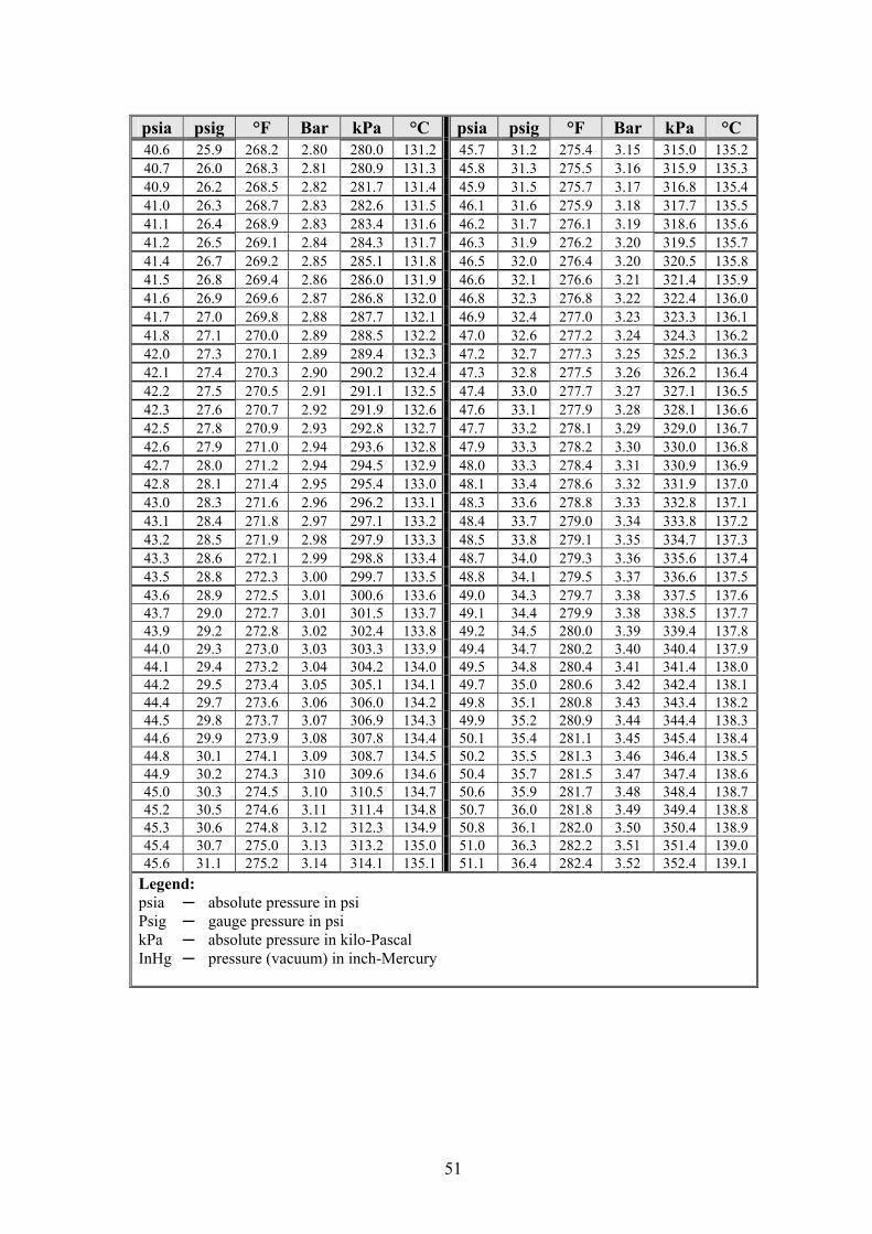
°C kPa Bar °F psig psia °C kPa Bar °F psig psia 135.2 315.0 3.15 275.4 31.2 45.7 131.2280.0 2.80 268.2 25.9 40.6 135.3 315.9 3.16 275.5 31.3 45.8 131.3280.9 2.81 268.3 26.0 40.7 135.4 316.8 3.17 275.7 31.5 45.9 131.4281.7 2.82 268.5 26.2 40.9 135.5 317.7 3.18 275.9 31.6 46.1 131.5282.6 2.83 268.7 26.3 41.0 135.6 318.6 3.19 276.1 31.7 46.2 131.6283.4 2.83 268.9 26.4 41.1 135.7 319.5 3.20 276.2 31.9 46.3 131.7284.3 2.84 269.1 26.5 41.2 135.8 320.5 3.20 276.4 32.0 46.5 131.8285.1 2.85 269.2 26.7 41.4 135.9 321.4 3.21 276.6 32.1 46.6 131.9286.0 2.86 269.4 26.8 41.5 136.0 322.4 3.22 276.8 32.3 46.8 132.0286.8 2.87 269.6 26.9 41.6 136.1 323.3 3.23 277.0 32.4 46.9 132.1287.7 2.88 269.8 27.0 41.7 136.2 324.3 3.24 277.2 32.6 47.0 132.2288.5 2.89 270.0 27.1 41.8 136.3 325.2 3.25 277.3 32.7 47.2 132.3289.4 2.89 270.1 27.3 42.0 136.4 326.2 3.26 277.5 32.8 47.3 132.4290.2 2.90 270.3 27.4 42.1 136.5 327.1 3.27 277.7 33.0 47.4 132.5291.1 2.91 270.5 27.5 42.2 136.6 328.1 3.28 277.9 33.1 47.6 132.6291.9 2.92 270.7 27.6 42.3 136.7 329.0 3.29 278.1 33.2 47.7 132.7292.8 2.93 270.9 27.8 42.5 136.8 330.0 3.30 278.2 33.3 47.9 132.8293.6 2.94 271.0 27.9 42.6 136.9 330.9 3.31 278.4 33.3 48.0 132.9294.5 2.94 271.2 28.0 42.7 137.0 331.9 3.32 278.6 33.4 48.1 133.0295.4 2.95 271.4 28.1 42.8 137.1 332.8 3.33 278.8 33.6 48.3 133.1296.2 2.96 271.6 28.3 43.0 137.2 333.8 3.34 279.0 33.7 48.4 133.2297.1 2.97 271.8 28.4 43.1 137.3 334.7 3.35 279.1 33.8 48.5 133.3297.9 2.98 271.9 28.5 43.2 137.4 335.6 3.36 279.3 34.0 48.7 133.4298.8 2.99 272.1 28.6 43.3 137.5 336.6 3.37 279.5 34.1 48.8 133.5299.7 3.00 272.3 28.8 43.5 137.6 337.5 3.38 279.7 34.3 49.0 133.6300.6 3.01 272.5 28.9 43.6 137.7 338.5 3.38 279.9 34.4 49.1 133.7301.5 3.01 272.7 29.0 43.7 137.8 339.4 3.39 280.0 34.5 49.2 133.8302.4 3.02 272.8 29.2 43.9 137.9 340.4 3.40 280.2 34.7 49.4 133.9303.3 3.03 273.0 29.3 44.0 138.0 341.4 3.41 280.4 34.8 49.5 134.0304.2 3.04 273.2 29.4 44.1 138.1 342.4 3.42 280.6 35.0 49.7 134.1305.1 3.05 273.4 29.5 44.2 138.2 343.4 3.43 280.8 35.1 49.8 134.2306.0 3.06 273.6 29.7 44.4 138.3 344.4 3.44 280.9 35.2 49.9 134.3306.9 3.07 273.7 29.8 44.5 138.4 345.4 3.45 281.1 35.4 50.1 134.4307.8 3.08 273.9 29.9 44.6 138.5 346.4 3.46 281.3 35.5 50.2 134.5308.7 3.09 274.1 30.1 44.8 138.6 347.4 3.47 281.5 35.7 50.4 134.6309.6 310 274.3 30.2 44.9 138.7 348.4 3.48 281.7 35.9 50.6 134.7310.5 3.10 274.5 30.3 45.0 138.8 349.4 3.49 281.8 36.0 50.7 134.8311.4 3.11 274.6 30.5 45.2 138.9 350.4 3.50 282.0 36.1 50.8 134.9312.3 3.12 274.8 30.6 45.3 139.0 351.4 3.51 282.2 36.3 51.0 135.0313.2 3.13 275.0 30.7 45.4 139.1 352.4 3.52 282.4 36.4 51.1 135.1314.1 3.14 275.2 31.1 45.6
Legend: psia absolute pressure in psi Psig gauge pressure in psi kPa absolute pressure in kilo-Pascal InHg pressure (vacuum) in inch-Mercury

52
VESSEL ASSEMBLY
53
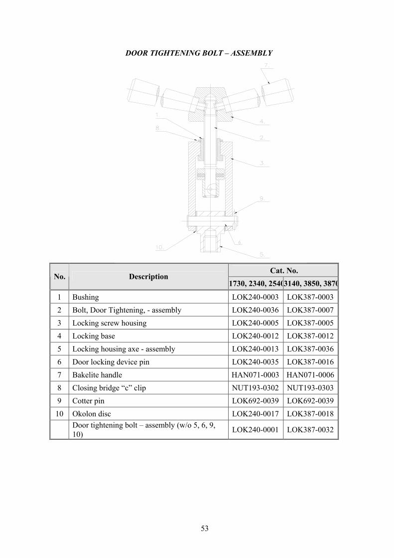
DOOR TIGHTENING BOLT – ASSEMBLY
Cat. No. No. Description
1730, 2340, 25403140, 3850, 3870
1 Bushing LOK240-0003 LOK387-0003 2 Bolt, Door Tightening, - assembly LOK240-0036 LOK387-0007 3 Locking screw housing LOK240-0005 LOK387-0005 4 Locking base LOK240-0012 LOK387-0012 5 Locking housing axe - assembly LOK240-0013 LOK387-0036 6 Door locking device pin LOK240-0035 LOK387-0016 7 Bakelite handle HAN071-0003 HAN071-00068 Closing bridge “c” clip NUT193-0302 NUT193-0303 9 Cotter pin LOK692-0039 LOK692-0039 10 Okolon disc LOK240-0017 LOK387-0018
Door tightening bolt – assembly (w/o 5, 6, 9, 10) LOK240-0001 LOK387-0032

54
OUTER CABINET - ASSEMBLY

55
WATER RESERVOIR
WATER OUTLET STRAINER
Description Cat. No.
Cap, water strainer, ¼” FIL175-0027
Screen, 400 Micron, For Strainer 1/4" FIL175-0046
Gasket, 4mm, Silicon, for 1/4" Strainer GAS082-0008
Strainer, Water, Housing + cap, 1/4 FIL175-0051
Cap Gasket Strainer element
Strainer Housing

56
14 VALVES NUMBERING The valves in the drawing and the manual are numbered according to their
function. The following list includes all the valve numbers that are in use in Tuttnauer
0. FUNCTION
01. Change-over : steam / electricity 02. Locking door cylinder (front door) 03. Locking door cylinder (Rear door)
1. FEED WATER
11. Feed water – cool jacket 12. Feed water – cool heat exchanger 13. Feed water – cool fast exhaust 14. Feed water – to reservoir 15. feed water – to vacuum pump 16. Water outlet 17. Shut 18. Feed water – to ejector
2. MINERAL FREE WATER
21. Mineral free water - inlet 22. Detergent 23. To spray 24. Recycling inlet 25. Recycling outlet
3. COMPRESSED AIR
31. Air inlet 32. Air inlet - to chamber 33. To splash cooling pipe 34 – 1. To door 1 seal 34 – 2. To door 2 seal 38 – 1. Open door 1 38 – 2. Open door 2 39 – 1. Close door 1 39 – 2. Close door 2
4. AIR
41. Air release N.C. 42. Air release N.O. 43. Filtered air - inlet 44. Air Inlet 45. Aeration
5. VACUUM
51. Vacuum - break 52. Vacuum - to pump 53.1 Vacuum - from door 1 seal 53-2. Vacuum - from door 2 seal
57
6. DRAIN
61. Drain – from reservoir 62. Drain – from jacket overflow 63. Drain – from vacuum pump / ejector 64. Drain – from chamber 65. Drain – from cooler 66. Drain – from sanitary filter 67. Drain – from steam generator 68. Drain – jacket 69. Drain – condense from seal
7. EXHAUST
70. Exhaust – from chamber 71. Exhaust – to reservoir 72. Exhaust – to drain 73. Fast exhaust 74. Slow exhaust 75. Exhaust to ejector / to vacuum pump 76. Exhaust – from heat exchanger 77. Exhaust – from steam generator 78. Exhaust through heat exchanger (pre-vacuum stage only) 79. Jacket steam trap
8. GAS
81. Inlet 82. Main inlet 83. Inlet through humidifier
9. STEAM
90. Steam – from building source 91. Steam – to jacket (From outer source) 92. Steam – inlet 93. Steam – to chamber 94 – 1. Steam – to door 1 seal 94 – 2. Steam – to door 2 seal 95. Steam – to heat exchanger 96. Steam – to sanitary filter 97. Steam – from steam generator 98. Steam – to activate ejector
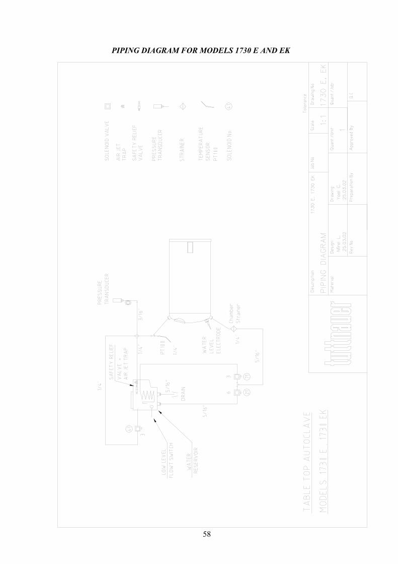
58
PIPING DIAGRAM FOR MODELS 1730 E AND EK

59
PIPING DIAGRAM FOR MODELS: E AND EK EXCEPT 1730
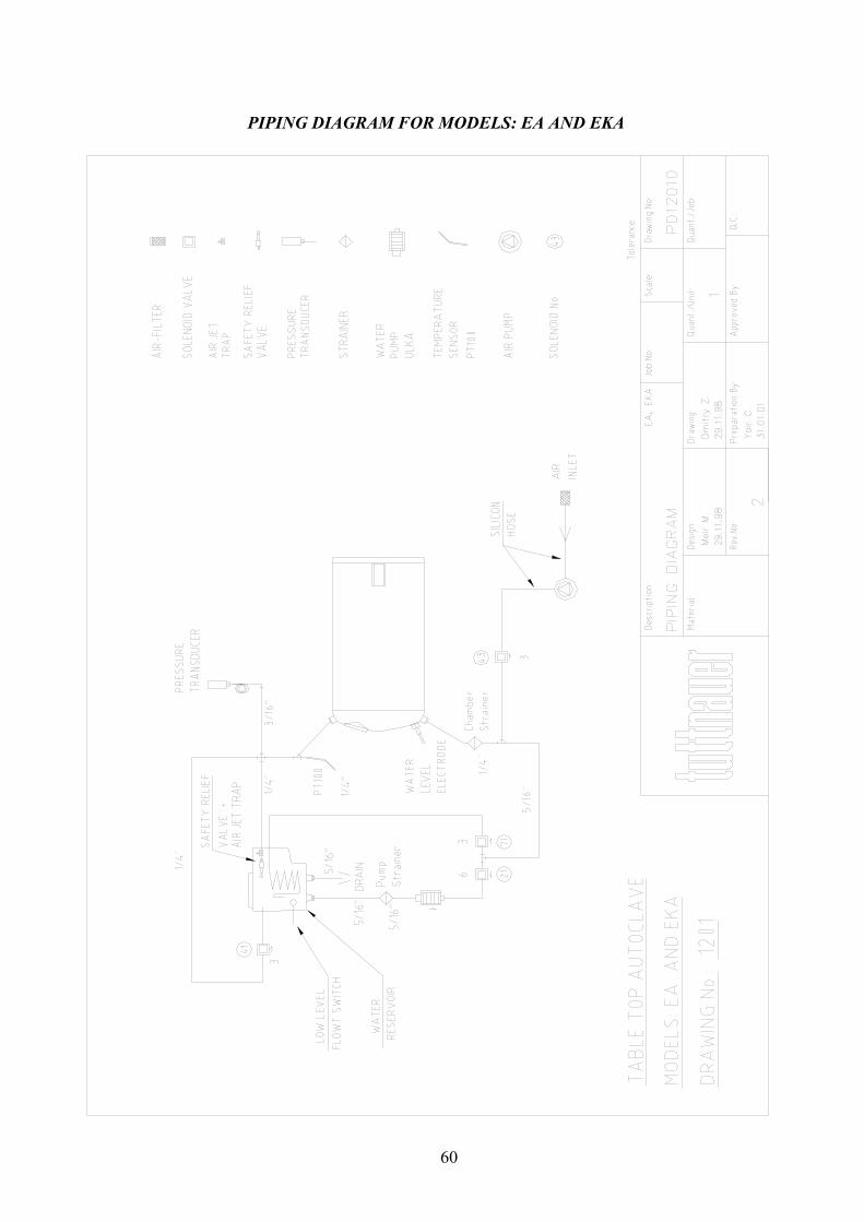
60
PIPING DIAGRAM FOR MODELS: EA AND EKA

61
ELECTRICAL DIAGRAM FOR MODELS 1730 E, EK

62
ELECTRICAL DIAGRAM FOR MODELS 2340/2540 E, EK

63
ELECTRICAL DIAGRAM FOR MODELS 2340/2540 EA, EKA
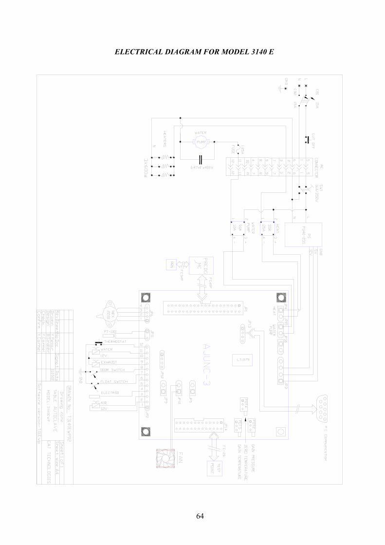
64
ELECTRICAL DIAGRAM FOR MODEL 3140 E
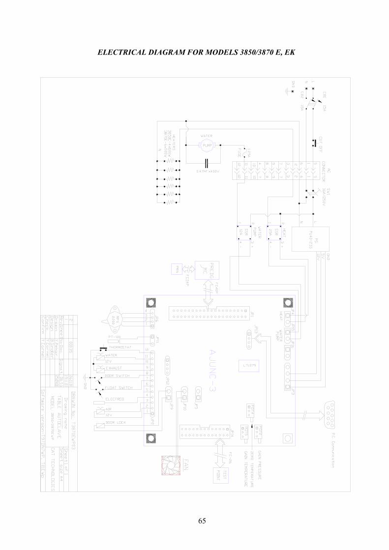
65
ELECTRICAL DIAGRAM FOR MODELS 3850/3870 E, EK

66
ELECTRICAL DIAGRAM FOR MODELS 3850/3870 EA, EKA