man205-0343001en rev k changes not highlighted · cat. no. man205-0343001en rev. k tuttnauer europe...
TRANSCRIPT

TECHNICIAN MANUAL
Electronic Table -Top Autoclaves Model ELARA
Cat. No. MAN205-0343001EN Rev. K
Tuttnauer Europe b.v., Paardeweide 36, 4824 EH, Breda, P.O. Box 7191, 4800 GD Breda, Netherlands. +31/76-5423510, Fax: +31/76-5423540

Page 1 of 87 Pages
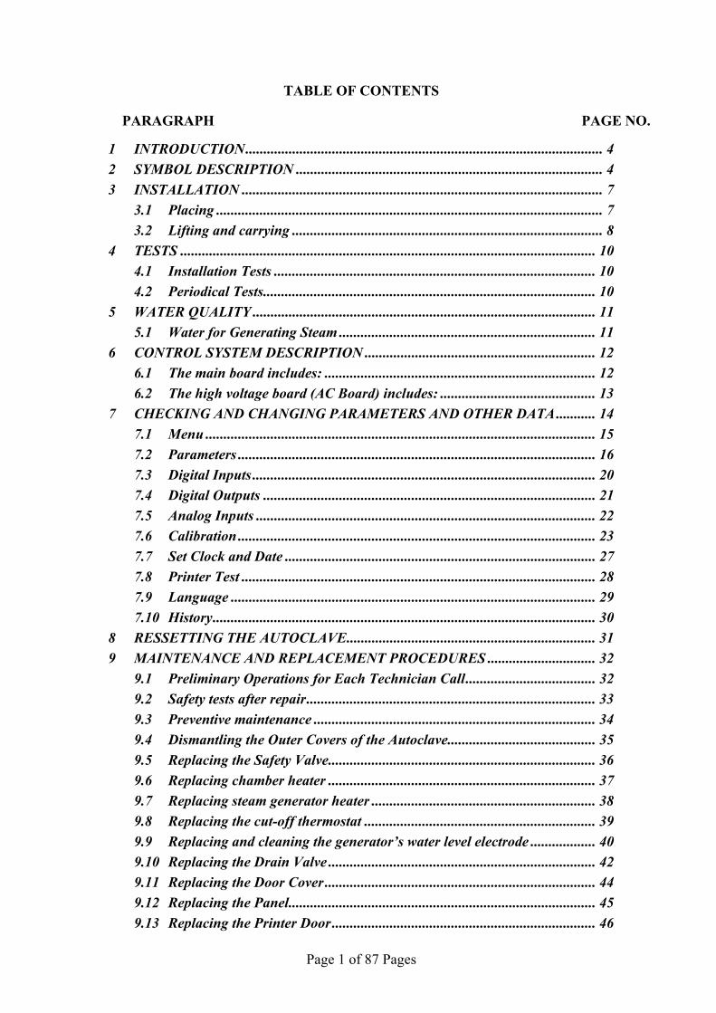
TABLE OF CONTENTS PARAGRAPH PAGE NO. 1 INTRODUCTION................................................................................................... 4 2 SYMBOL DESCRIPTION ..................................................................................... 4 3 INSTALLATION .................................................................................................... 7
3.1 Placing ........................................................................................................... 7 3.2 Lifting and carrying ...................................................................................... 8
4 TESTS ................................................................................................................... 10 4.1 Installation Tests ......................................................................................... 10 4.2 Periodical Tests............................................................................................ 10
5 WATER QUALITY ............................................................................................... 11 5.1 Water for Generating Steam ....................................................................... 11
6 CONTROL SYSTEM DESCRIPTION ................................................................ 12 6.1 The main board includes: ........................................................................... 12 6.2 The high voltage board (AC Board) includes: ........................................... 13
7 CHECKING AND CHANGING PARAMETERS AND OTHER DATA........... 14 7.1 Menu ............................................................................................................ 15 7.2 Parameters ................................................................................................... 16 7.3 Digital Inputs ............................................................................................... 20 7.4 Digital Outputs ............................................................................................ 21 7.5 Analog Inputs .............................................................................................. 22 7.6 Calibration ................................................................................................... 23 7.7 Set Clock and Date ...................................................................................... 27 7.8 Printer Test .................................................................................................. 28 7.9 Language ..................................................................................................... 29 7.10 History.......................................................................................................... 30
8 RESSETTING THE AUTOCLAVE..................................................................... 31 9 MAINTENANCE AND REPLACEMENT PROCEDURES .............................. 32
9.1 Preliminary Operations for Each Technician Call.................................... 32 9.2 Safety tests after repair................................................................................ 33 9.3 Preventive maintenance .............................................................................. 34 9.4 Dismantling the Outer Covers of the Autoclave......................................... 35 9.5 Replacing the Safety Valve.......................................................................... 36 9.6 Replacing chamber heater .......................................................................... 37 9.7 Replacing steam generator heater .............................................................. 38 9.8 Replacing the cut-off thermostat ................................................................ 39 9.9 Replacing and cleaning the generator’s water level electrode .................. 40 9.10 Replacing the Drain Valve .......................................................................... 42 9.11 Replacing the Door Cover ........................................................................... 44 9.12 Replacing the Panel..................................................................................... 45 9.13 Replacing the Printer Door......................................................................... 46

Page 2 of 87 Pages
9.14 Replacing the Door Handle ........................................................................ 47 9.15 Replacing the Plastic Handle Cover ........................................................... 48 9.16 Replacing the Printer .................................................................................. 49 9.17 Replacing the Door Switch.......................................................................... 50 9.18 Replacing the fuse on the Electronic Board............................................... 51 9.19 Replacing the fuse of the transformer ........................................................ 52 9.20 Replacing the water pump........................................................................... 53 9.21 Replacing the vacuum pump....................................................................... 54 9.22 Replacing the Plunger or Coil of the 1/4" Solenoid Valve........................ 55 9.23 Replacing the Electronic Boards ................................................................ 56 9.24 Replacing the switch.................................................................................... 61 9.25 Draining the generator................................................................................ 62 9.26 Emergency Door Opening........................................................................... 63 9.27 Cleaning and replacing the water reservoirs.............................................. 65 9.28 Cleaning and replacing the water reservoirs.............................................. 67 9.29 Replacing the cut-of thermostat.................................................................. 68 9.30 Replacing the PT100 of the chamber's heating element ........................... 69 9.31 Replacing the pressure transducer ............................................................. 70
10 TROUBLESHOOTING........................................................................................ 71 10.1 Preliminary Check....................................................................................... 71 10.2 Troubleshooting procedure......................................................................... 72
11 LIST OF SPARE PARTS ..................................................................................... 78 12 PRESSURE VS TEMPERATURE FOR SATURATED STEAM ...................... 81
Page 3 of 87 Pages
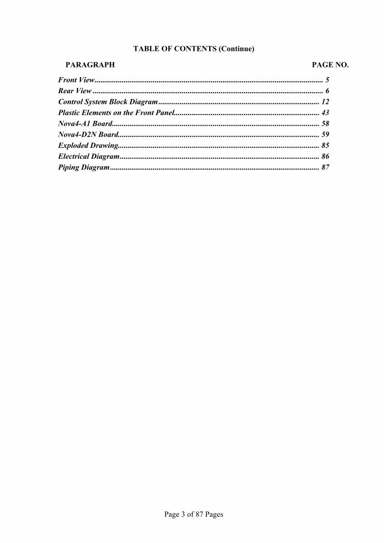
TABLE OF CONTENTS (Continue)
PARAGRAPH PAGE NO. Front View...................................................................................................................... 5 Rear View ....................................................................................................................... 6 Control System Block Diagram ................................................................................... 12 Plastic Elements on the Front Panel........................................................................... 43 Nova4-A1 Board........................................................................................................... 58 Nova4-D2N Board........................................................................................................ 59 Exploded Drawing........................................................................................................ 85 Electrical Diagram....................................................................................................... 86 Piping Diagram............................................................................................................ 87

Page 4 of 87 Pages
1 INTRODUCTION This manual, together with the operator’s manual, forms the complete edition
of the Operation and Maintenance instructions. This manual is intended for the use of the technician. It is forbidden for unqualified and unauthorized personnel to service the autoclave in accordance with the instructions in this manual. Any unauthorized service may result in the invalidation of the manufacturer’s guarantee.
The qualified technician shall be an authorized electrician with the right qualifications in electronics and shall be familiar with the local technical/electrical regulations.
2 SYMBOL DESCRIPTION
Caution! Consult accompanying documents
Caution! Hot surface
Caution! Hot steam.
Protective earth (Ground)
Page 5 of 87 Pages
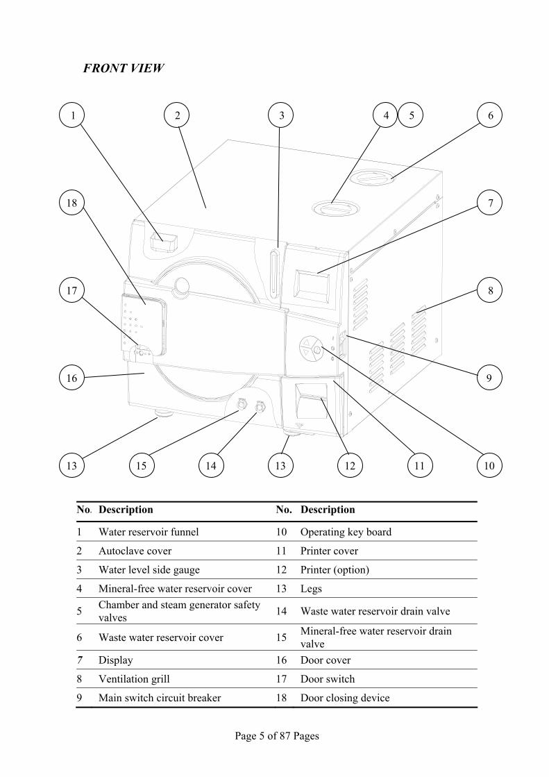
FRONT VIEW
No. Description No. Description
1 Water reservoir funnel 10 Operating key board
2 Autoclave cover 11 Printer cover
3 Water level side gauge 12 Printer (option)
4 Mineral-free water reservoir cover 13 Legs
5 Chamber and steam generator safety valves 14 Waste water reservoir drain valve
6 Waste water reservoir cover 15 Mineral-free water reservoir drain valve
7 Display 16 Door cover
8 Ventilation grill 17 Door switch
9 Main switch circuit breaker 18 Door closing device
5 4 6
8
9
101115 13 12
1 2 3
718
17
16
13 14

Page 6 of 87 Pages
REAR VIEW
No. Description
1 Mineral-free water reservoir cover
2 Waste water reservoir cover
3 Ventilation grills
4 Air filter service cover
5 Opening for calibration
6 Main power electric cable socket
5
4
3
1
2
3
6

Page 7 of 87 Pages
3 INSTALLATION 3.1 Placing
CAUTION:
The installation and all operations described in this chapter must be done only by an authorized technician.
3.1.1 Unpacking the autoclave Unpack the autoclave and inspect for mechanical damage
upon receipt. Observe packing method and retain packing materials until the unit has been inspected. Mechanical inspection involves checking for signs of physical damage such as: scratched panel surfaces, broken knobs, etc.
To avoid injuries, lifting and carrying of the autoclave should be done with at least two persons or by using a fork-lift or any other mechanical aid.
3.1.2 Installation preparations
1. Check and verify that the counter carrying the autoclave is a rigid and leveled surface and can carry a load of 80kg.
2. Check and verify that the counter dimensions are, at least, 55cmW x 65cmD (22”W x 25”D)
3. Keep the back and the sides of the autoclave approximately 5 cm (2”) and away from the wall to allow ventilation and facilitate the device disconnection.
4. If placed in a cabinet, verify that the rear of the cabinet is open to allow ventilation.
Insufficient space for ventilation may result in an increase of the autoclave's temperature that may damage the instrument.
5. It is recommended that enough space be left around the autoclave to give a technician access for servicing the machine.
6. Check and verify that the room ventilation is 10 cycles per hour Minimum.
7. Check and verify that the ambient temperature range is 5ºC-40ºC (it is preferable not to exceed 30ºC).
8. Check and verify that the ambient relative humidity does not exceed 85%
3.1.3 Connections to Utility Supplies 1. Check and verify that the power supply is a 1 phase,
200/208/230Vac ±10%, 50/60Hz (as appropriate), 10A supply.
2. Check and verify grounding of the autoclave. 3. Check and verify that the electrical net is protected with a
current leakage safety relay. 3.1.4 Final adjustments Once the autoclave is installed, the following operations have to
be performed before operating any cycle:

Page 8 of 87 Pages
1. Setting clock and date (See instruction in the user manual clause 6.2).
2. Adjust parameter ATMPressure according to the altitude of the autoclave (See instruction for adjusting parameters ATMPressure clause 7.2.6)
3.1.5 Operating the autoclave 1 Plug the power cord into the power socket. 2 Turn on the main switch circuit breaker (see front view). 3 Fill the mineral water reservoir with water (see "Filling
the Mineral-Free Water Reservoir") as follows: 3.1 Fill 4 liter by pouring water in the upper filling
opening. 3.2 Fill the remaining quantity by pouring water
gently, into the front funnel until it reaches the required level on the side gauge. It is preferable to use a carafe
4 Select "Vacuum Test" cycle to avoid operating the steam generator and the heating elements.
5 Open the door of the autoclave and remove the trays and the packaging material.
6 Insert a paper roll in the printer (see printer handling). 7 Close the door and perform a Vacuum Test. If the test
fails perform another test since the fail may be a result of moister in the air. If the second test fails too, refer to the troubleshooting.
8 Select the B&D Test cycle. At this stage the chamber is heating up and the generator
builds up pressure. Wait approximately 20 minutes (from selecting the B&D Test). 9 Explain and instruct the operator as follows (use the
operation manual as reference): 9.1 Operation principals of the autoclave. 9.2 Preparation for sterilizing instruction including
loading instructions. 9.3 Intended use of each cycle. 9.4 Selecting a cycle. 9.5 Water filling method. 9.6 Displayed error and operational messages. 9.7 Monitoring and changing parameters. 9.8 Printer handling. 9.9 Maintenance instructions
10 Perform a B&D test with a chemical indicator. 11 The operator shall perform a cycle under supervision of
the technician.
3.2 Lifting and carrying CAUTION:

Page 9 of 87 Pages
Before moving the autoclave, Make sure that the electric cord is disconnected from the power, and there is no pressure in the chamber and in the generator. Attention! The pressure of the generator does not decrease immediately when the equipment is turned off. Wait approx. ½ an hour to verify that the pressure decreased to atmospheric pressure. 1. Disconnect the power supply cord. 2. Drain the water from both reservoirs. To avoid injuries, lifting and carrying should be done with at least two persons or by using a fork-lift or any other mechanical aid.
Do not drop the device!

Page 10 of 87 Pages
4 TESTS 4.1 Installation Tests The service technician shall perform the following preliminary
checks before operating the autoclave: a. Integrity Check Perform a visual check to verify that there are no dents, scratches,
broken gauges, etc. b Leveling Check Check (visual check) that the surface carrying the autoclave is
leveled. c. Leakage current test Check the precise operation of the earth leakage relay. d. Continuity Check Check the continuity of the grounding connection. At this stage operate the autoclave and continue with the tests: e. Safety Check Check the safety elements; safety valve and the door locking
mechanisms. f. Programs Check Run basic programs of the autoclave and check the operation
sequences, the sterilization parameters etc. g. Validation Validate the sterilization cycles, taking in consideration the interface
of packaging/goods/autoclave. After the above steps are performed, the autoclave is ready for operation. 4.2 Periodical Tests
PERIOD TEST 1 month Test the safety valve by operating it.
6 months Remove the autoclave’s cover, tighten the heaters’ screws and electrical connections, valves and connectors in the control box.Check the continuity of the grounding connections. Check the temperature and pressure calibration. Perform validation of the autoclave. Check the precise operation of the earth leakage relay. Check that the autoclave is leveled. Check the safety elements; safety valve, safety and cut-off thermostats door locking mechanisms. Run basic programs of the autoclave and check the operation sequences, the sterilization parameters etc. Check the water reservoir, piping, plastic parts and electric wires.Check and tighten the piping joints to avoid leakage. Check and tighten all screw connections in the control box, heaters and valves and instrumentation.
Year
Calibrate the temperature and pressure once a year or in reference to local rules or regulations (refer to the section on Calibration).
5 years Observe the closing device for excessive wear Safety tests (pressure vessel, efficiency, electrical) shall be performed in accordance with local rules or regulations, by an authorized inspector.
Only an authorized technician shall perform the 6-months and yearly tests!
Page 11 of 87 Pages
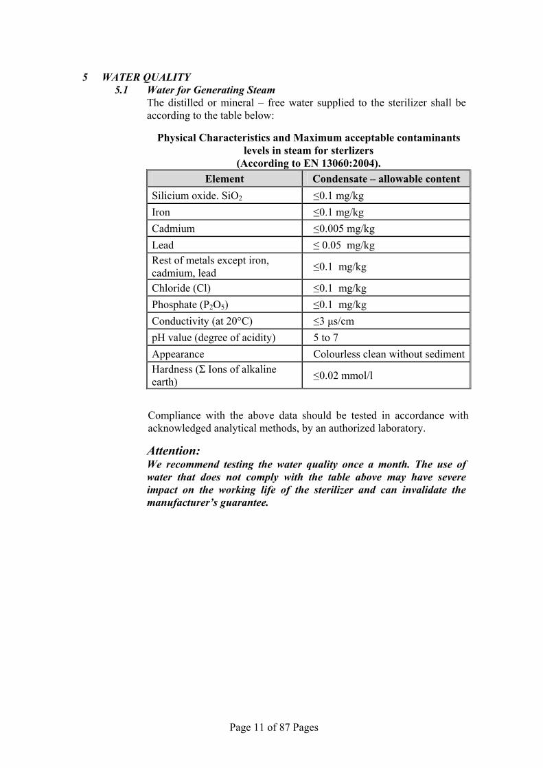
5 WATER QUALITY
5.1 Water for Generating Steam The distilled or mineral – free water supplied to the sterilizer shall be
according to the table below:
Physical Characteristics and Maximum acceptable contaminants levels in steam for sterlizers
(According to EN 13060:2004). Element Condensate – allowable content
Silicium oxide. SiO2 ≤0.1 mg/kg Iron ≤0.1 mg/kg Cadmium ≤0.005 mg/kg Lead ≤ 0.05 mg/kg Rest of metals except iron, cadmium, lead ≤0.1 mg/kg
Chloride (Cl) ≤0.1 mg/kg Phosphate (P2O5) ≤0.1 mg/kg Conductivity (at 20°C) ≤3 µs/cm pH value (degree of acidity) 5 to 7
Appearance Colourless clean without sedimentHardness (Σ Ions of alkaline earth) ≤0.02 mmol/l
Compliance with the above data should be tested in accordance with acknowledged analytical methods, by an authorized laboratory.
Attention: We recommend testing the water quality once a month. The use of
water that does not comply with the table above may have severe impact on the working life of the sterilizer and can invalidate the manufacturer’s guarantee.
Page 12 of 87 Pages
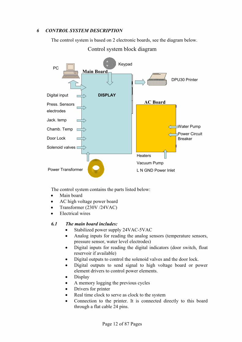
6 CONTROL SYSTEM DESCRIPTION
The control system is based on 2 electronic boards, see the diagram below.
Control system block diagram
The control system contains the parts listed below: • Main board • AC high voltage power board • Transformer (230V /24VAC) • Electrical wires
6.1 The main board includes:
• Stabilized power supply 24VAC-5VAC • Analog inputs for reading the analog sensors (temperature sensors,
pressure sensor, water level electrodes) • Digital inputs for reading the digital indicators (door switch, float
reservoir if available) • Digital outputs to control the solenoid valves and the door lock. • Digital outputs to send signal to high voltage board or power
element drivers to control power elements. • Display • A memory logging the previous cycles • Drivers for printer • Real time clock to serve as clock to the system • Connection to the printer. It is connected directly to this board
through a flat cable 24 pins.
Digital input
Press. Sensors electrodes
Jack. temp
Chamb. Temp
Door Lock
Solenoid valves
Water Pump
Power Circuit Breaker
Heaters
Vacuum Pump
L N GND Power Inlet
DISPLAY
Keypad
DPU30 Printer
PC
Power Transformer
AC Board
Main Board

Page 13 of 87 Pages
6.2 The high voltage board (AC Board) includes: • High power outputs to control the heaters and the pumps. • Circuit breaker • The board provides four outputs for four high AC devices as
follows: 1. Steam generator heater (2200 Watt). 2. Chamber wall heater (500 Watt). 3. Vacuum pump. 4. Water pump.
• Connection between the 2 cards
Page 14 of 87 Pages
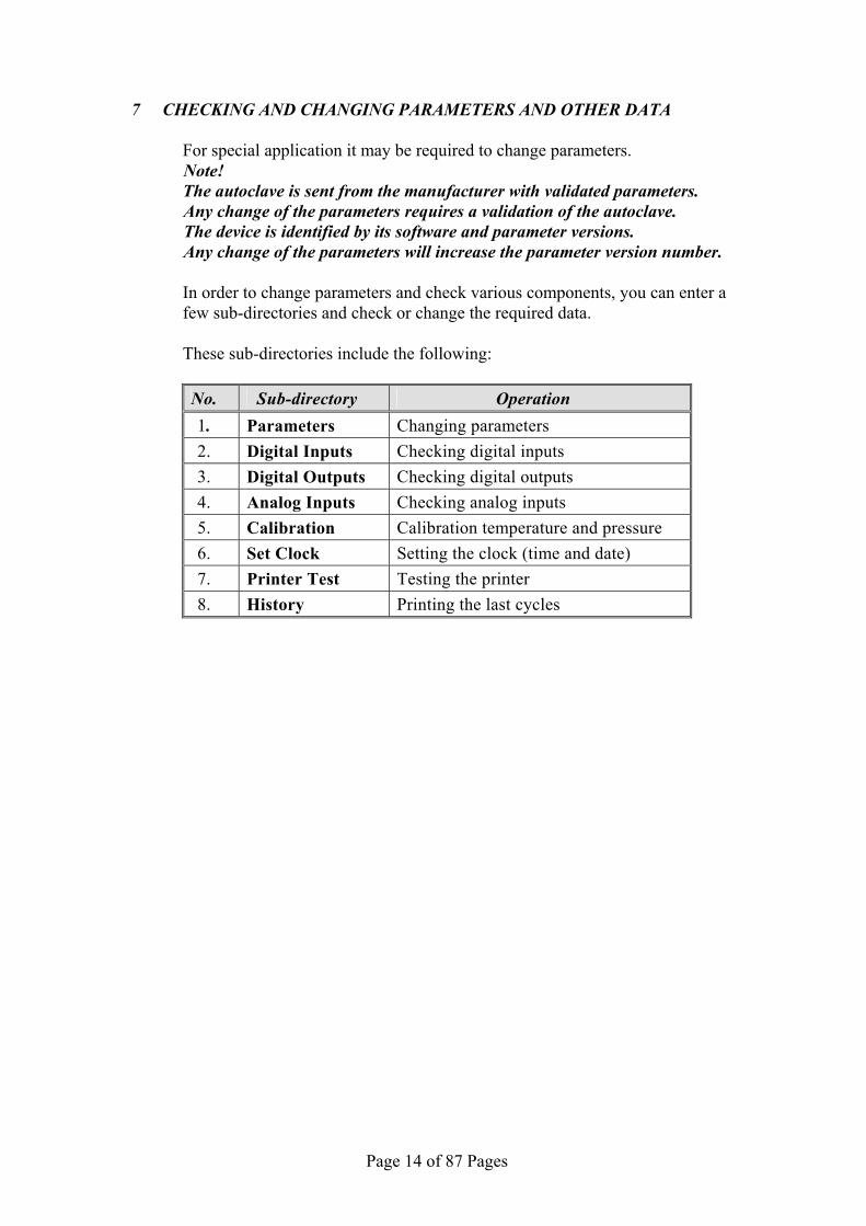
7 CHECKING AND CHANGING PARAMETERS AND OTHER DATA For special application it may be required to change parameters. Note! The autoclave is sent from the manufacturer with validated parameters. Any change of the parameters requires a validation of the autoclave. The device is identified by its software and parameter versions. Any change of the parameters will increase the parameter version number. In order to change parameters and check various components, you can enter a
few sub-directories and check or change the required data. These sub-directories include the following:
No. Sub-directory Operation 1. Parameters Changing parameters 2. Digital Inputs Checking digital inputs 3. Digital Outputs Checking digital outputs 4. Analog Inputs Checking analog inputs 5. Calibration Calibration temperature and pressure 6. Set Clock Setting the clock (time and date) 7. Printer Test Testing the printer 8. History Printing the last cycles
Page 15 of 87 Pages
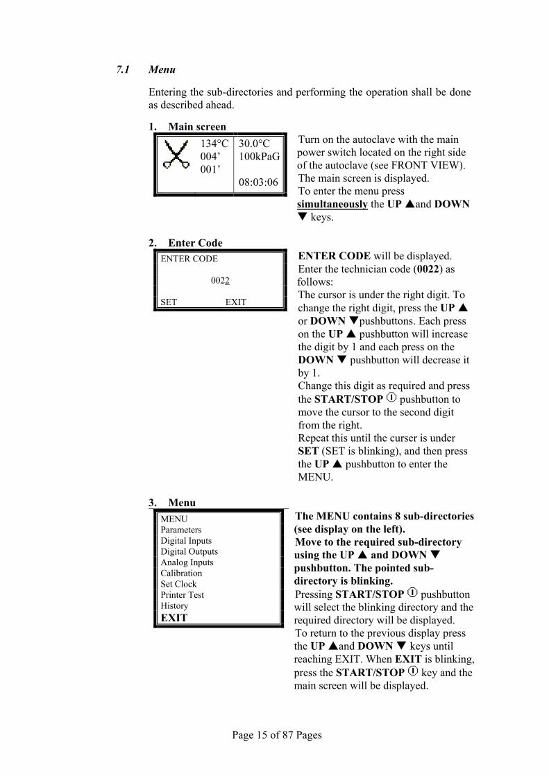
7.1 Menu
Entering the sub-directories and performing the operation shall be done as described ahead.
1. Main screen
134°C004’ 001’
30.0°C 100kPaG
08:03:06
Turn on the autoclave with the main power switch located on the right side of the autoclave (see FRONT VIEW). The main screen is displayed. To enter the menu press simultaneously the UP and DOWN
keys.
2. Enter Code ENTER CODE
0022 SET EXIT
ENTER CODE will be displayed. Enter the technician code (0022) as follows: The cursor is under the right digit. To change the right digit, press the UP or DOWN pushbuttons. Each press on the UP pushbutton will increase the digit by 1 and each press on the DOWN pushbutton will decrease it by 1. Change this digit as required and press the START/STOP pushbutton to move the cursor to the second digit from the right. Repeat this until the curser is under SET (SET is blinking), and then press the UP pushbutton to enter the MENU.
3. Menu
MENU Parameters Digital Inputs Digital Outputs Analog Inputs Calibration Set Clock Printer Test History EXIT
The MENU contains 8 sub-directories (see display on the left). Move to the required sub-directory using the UP and DOWN pushbutton. The pointed sub-directory is blinking. Pressing START/STOP pushbutton will select the blinking directory and the required directory will be displayed. To return to the previous display press the UP and DOWN keys until reaching EXIT. When EXIT is blinking, press the START/STOP key and the main screen will be displayed.

Page 16 of 87 Pages
7.2 Parameters
This section describes the parameters, how they affect the process and the way to change them.
Listed bellow are all the available parameters. Each section describes the parameter, the minimum and maximum
allowed values and the changing resolution. Also included are the pre-set values of the parameters for each cycle (default value).
NOTE: • If a parameter is modified, the only way to return to the original
value is to manually reenter it. • A global parameter is a parameter that by changing its value in
one program, it is changed in all the other programs to receive the same value.
• To change a non-global value, i.e. specific parameter for each program, choose first the required sterilization program in the main screen of the autoclave and then enter the MENU and the sub-directory PARAMETERS.
7.2.1 Ster Temp This parameter will set the desired temperature for sterilization
Resolution: 0.1°C Minimum value: Default value Maximum value: 136°C
Cycle Flash 134
P134
Wdry 134
No Dry
121
Wdry 121
Delicate
B&D Test
Vacuum
Test Default Value 134 134 134 121 121 121 Fixed
value Fixed value
7.2.2 Ster Time This parameter will set the time desired for sterilization.
Resolution: 0.1 min Minimum value: Default value Maximum value: 99.9 min
Cycle Flash 134
P134
Wdry 134
No Dry
121
Wdry 121
Delicate
B&D Test
Vacuum
Test Default Value 4 18 4 20 20 20 Fixed
value Fixed value

Page 17 of 87 Pages
7.2.3 Dry Time
This parameter will set the time desired for drying.
Resolution: 0.1 min Minimum value: Default value Maximum value: 99.9 min
Cycle Flash 134
P134
Wdry 134
No Dry
121
Wdry 121
Delicate
B&D Test
Vacuum
Test Default Value 1 20 20 0 20 0 Fixed
value Fixed value
7.2.4 SterPressAdd
This defines the required addition to the sterilization pressure in
kPa in order to increase the sterilization temperature. For example, for a sterilization temperature of 121°C the
required pressure is 205 kPa. Since the system controls the sterilization process according to pressure, if SterPressAdd equals “0”, the system will maintain the pressure at 205 kPa . If the value is at 5 kPa, the system will be maintained at 210 kPa and the temperature will be 121.8°C, and so on.
Resolution: 0.1 kPa Minimum value: 0 kPa Maximum value: 40 kPa
Cycle Flash 134
P134
Wdry 134
No Dry
121
Wdry 121
Delicate
B&D Test
Vacuum
Test Default Value 9 9 9 9 9 9 Fixed
value Fixed value
7.2.5 End Temp
This parameter will determine the temperature in the chamber at
the end of the cycle.
Resolution: 0.1°C Minimum value: 50°C Maximum value:136°C
Cycle Flash 134
P134
Wdry 134
No Dry
121
Wdry 121
Delicate
B&D Test
Vacuum
Test Default Value 120 120 120 110 110 110 Fixed
value Fixed value
Page 18 of 87 Pages
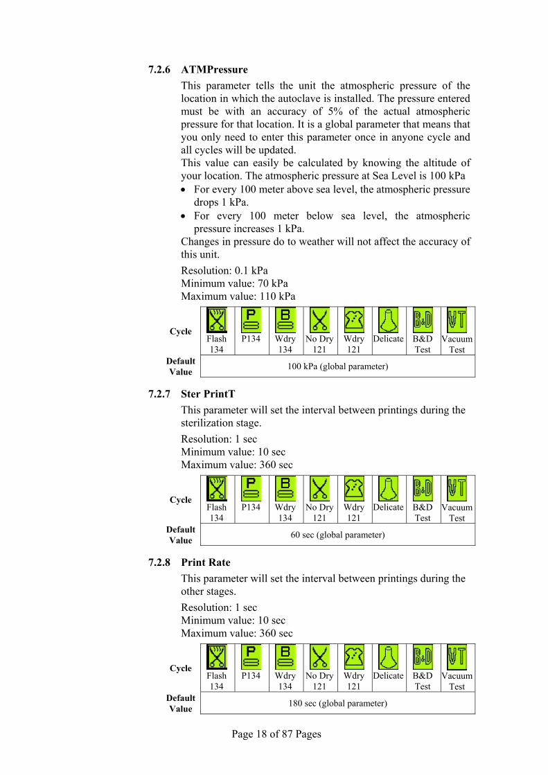
7.2.6 ATMPressure
This parameter tells the unit the atmospheric pressure of the location in which the autoclave is installed. The pressure entered must be with an accuracy of 5% of the actual atmospheric pressure for that location. It is a global parameter that means that you only need to enter this parameter once in anyone cycle and all cycles will be updated.
This value can easily be calculated by knowing the altitude of your location. The atmospheric pressure at Sea Level is 100 kPa • For every 100 meter above sea level, the atmospheric pressure
drops 1 kPa. • For every 100 meter below sea level, the atmospheric
pressure increases 1 kPa. Changes in pressure do to weather will not affect the accuracy of
this unit.
Resolution: 0.1 kPa Minimum value: 70 kPa Maximum value: 110 kPa
Cycle Flash 134
P134
Wdry 134
No Dry
121
Wdry 121
Delicate
B&D Test
Vacuum
Test Default Value 100 kPa (global parameter)
7.2.7 Ster PrintT
This parameter will set the interval between printings during the sterilization stage.
Resolution: 1 sec Minimum value: 10 sec Maximum value: 360 sec
Cycle Flash 134
P134
Wdry 134
No Dry
121
Wdry 121
Delicate
B&D Test
Vacuum
Test Default Value 60 sec (global parameter)
7.2.8 Print Rate
This parameter will set the interval between printings during the other stages.
Resolution: 1 sec Minimum value: 10 sec Maximum value: 360 sec
Cycle Flash 134
P134
Wdry 134
No Dry
121
Wdry 121
Delicate
B&D Test
Vacuum
Test Default Value 180 sec (global parameter)

Page 19 of 87 Pages
7.2.9 TempInF
This parameter enables the technician to set the displayed temperature in ºC or in ºF.
Changing this parameter in one of the cycles will change this parameter in all the other cycles to the value.
Access Code – available upon request Resolution – 1 Value – 0 or 1 If TemInf = 1 the temperature is expressed in ºF. If TemInf = 0 the temperature is expressed in ºC.
Cycle Flash 134
P134
Wdry 134
No Dry
121
Wdry 121
Delicate
B&D Test
Vacuum
Test Default Value 0 (global parameter)
7.2.10 PressInPSI
This parameter enables the technician to set the displayed pressure in kPa or in psig.
Changing this parameter in one of the cycles will change this parameter in all the other cycles to the value.
Access Code – available upon request Resolution – 1 Value – 0, 1 or 2 If PresInPSI = 0 the temperature is expressed in kPa. If PresInPSI = 1 the temperature is expressed in psia. If PresInPSI = 2 the temperature is expressed in psig.
Cycle Flash 134
P134
Wdry 134
No Dry
121
Wdry 121
Delicate
B&D Test
Vacuum
Test Default Value 0 (global parameter)

Page 20 of 87 Pages
7.3 Digital Inputs
This directory enables monitoring the status of the digital inputs. It is possible to view the digital inputs during cycle.
1. To move from one item to another item use the UP and DOWN pushbuttons.
2. To exit to the menu go to EXIT and when it is blinking press the START/STOP pushbuttons.
Displayed
item Displayed
symbol Operation Status
Thermostat disconnects the heaters.
The temperature is above the acceptable temperature.
Thermostat (not applicableon this model)
The temperature is below the acceptable temperature.
Senses water in the clean water reservoir.
The float doesn’t sense water in the clean water reservoir.
Float RESERV (not applicable on this model) The float senses water in the
clean water reservoir.
Senses if the door is open or closed.
The sensor senses the door is closed.
Door Switch
The sensor senses the door is open.
Senses water in the waste water reservoir.
The float doesn’t sense water in the waste water reservoir.
Float Res (not applicable on this model) The float senses water in the
waste water reservoir.

Page 21 of 87 Pages
7.4 Digital Outputs
This directory enables monitoring the status of the digital Outputs. It is possible to view the digital outputs during cycle.
1. To move from one item to another item use the UP and DOWN
pushbuttons. 2. To exit to the menu go to EXIT and when it is blinking press the
START/STOP pushbuttons.
Displayed item
Displayed symbol Operation Remarks
Not operating Air Operating Air valve (valve 43)
Not operating Vac valve Operating Vacuum valve (valve 52)
Not operating Chamb Steam Operating
Steam inlet valve to the chamber (valve 93)
Not operating Fast exh Operating
Fast exhaust valve to the reservoir (valve 71)
Not operating Option 1 Operating Optional
Not operating Wtr to Res Operating Mineral free water to reservoir (valve 21)
Not operating Air VacPump Operating
Air inlet valve to the vacuum pump (valve 44)
Not operating Water Valve Operating Optional
Not operating Option 2 Operating Optional
Locked position Door lock Unlocked position Door locking pin
Not operating Heater 1 Operating Steam generator heating element
Not operating Heater 2 Operating Chamber heating element
Not operating Vacuum pump Operating Vacuum pump
Not operating Water pump Operating Water pump
Off Buzzer Buzzing Buzzer
On Backlight Off Screen

Page 22 of 87 Pages
7.5 Analog Inputs
This directory enables to check the analog Inputs. It is possible to enter this directory while the autoclave is performing a cycle in order to check the devices sending these inputs. 1. To move from one item to another item use the UP and DOWN
pushbuttons. 2. To exit to the menu go to EXIT and when it is blinking press the
START/STOP key.
Displayed item Description
Chambpress Pressure inside the chamber
Chambtemp Temperature in the chamber
Coil Temp Temperature in jacket of the chamber
Gen Press Pressure in the steam generator
Electr Gen Level of water in the steam generator
ElectrLow This analog input measures the level of water in the clean water reservoir.
ElectrLow2 This analog input measures the level of water in the waste water reservoir.

Page 23 of 87 Pages
7.6 Calibration
7.6.1 Calibration components
This directory describes the calibration of 4 sensors in the Sensor name Sensor function
1. ChambPress Reads the pressure in the chamber. 2. ChambTemp Reads the temperature in the chamber. 3. CoilTemp Reads the temperature in the jacket. 4. GenPress Reads the pressure in the steam generator.
7.6.2 Required equipment for calibration
• PT Simulator (for temperature calibration). • Reference temperature sensor. • Reference pressure tool: pressure gauge.
7.6.3 Calibrating the sensors
ANALOG INPUTS ChambPress 113.4 Chamb Temp 082.8 CoilTemp 119.8 GenPress 298.7
Choose the sensor required to calibrate among the 4 sensors available with the UP and DOWN
keys. When it is blinking select it by pressing the START/STOP key.
CALIBRATION Change GainOffset Calc. GainOffset Restore Last Restore Default
EXIT
Move to Calc. GainOffset with the UP and DOWN keys, and then when it is blinking select it with the START/STOP key.
Calibrating the pressure in the chamber “ChambPress”
Calibrate the low pressure of the chamber To perform the low pressure calibration, insert your
reference pressure tool in the autoclave and operate a vacuum test. Open the autoclave’s door and read the value displayed on your tool. • AL (actual pressure low value): change the AL with
the value read by your reference tool (use UP and DOWN keys to increase and decrease the value and the START/STOP key to move ahead from digit to digit).
• RL (read pressure low value): change the RL with this same value (use UP and DOWN keys to increase and decrease the value and the START/STOP key to move ahead from digit to digit).
• To save the data move to SET by pressing the START/STOP key and when it is blinking press the UP key.
Page 24 of 87 Pages
Calibrate the high pressure of the chamber To perform the calibration of the high pressure, insert
your reference pressure tool in the autoclave and operate a program of 134°C. Perform the calibration when the autoclave reaches the sterilization stage. • AH (actual pressure high value): change the AH
with the value read by your reference tool (use UP and DOWN keys to increase and decrease the
value and the START/STOP key to move ahead from digit to digit).
• RH (read pressure high value): change the RH with this same value (use UP and DOWN keys to increase and decrease the value and the START/STOP key to move ahead from digit to digit).
• To save the data move to SET by pressing the START/STOP key and when it is blinking press the UP key.
Calibrating the temperature in the chamber “ChambTemp”
Calibrate the low temperature of the chamber To perform the calibration of the low temperature,
insert your reference temperature tool in the autoclave, near of the Pt100 of the chamber when the autoclave is cold. • AL (actual temperature low value): change the AL
with the value read by your reference tool (use UP and DOWN keys to increase and decrease the value and the START/STOP key to move ahead from digit to digit).
• RL (read temperature low value): change the RL with this same value (use UP and DOWN keys to increase and decrease the value and the START/STOP key to move ahead from digit to digit).
• To save the data move to SET by pressing the START/STOP key and when it is blinking press the UP key.
Calibrate the high temperature of the chamber To perform the calibration of the high temperature,
insert your reference pressure tool in the autoclave, near of the PT100 and operate a program of 134°C. Perform the calibration when the autoclave reaches the sterilization stage. • AH (actual temperature high value): change the AH
with the value read by your reference tool (use UP and DOWN keys to increase and decrease the
value and the START/STOP key to move ahead from digit to digit).
Page 25 of 87 Pages
• RH (read temperature high value): change the RH with this same value (use UP and DOWN keys to increase and decrease the value and the START/STOP key to move ahead from digit to digit).
• To save the data move to SET by pressing the START/STOP key and when it is blinking press the UP key.
Calibrating the temperature in the jacket “CoilTemp”
Calibrate the low temperature of the jacket To perform the calibration of the low temperature,
insert the reference temperature tool into the autoclave, near the PT100 of the jacket (under the insulation blanket) when the autoclave is cold. • AL (actual temperature low value): change the AL
with the value read by your reference tool (use UP and DOWN keys to increase and decrease the
value and the START/STOP key to move ahead from digit to digit).
• RL (read temperature low value): change the RL with this same value (use UP and DOWN keys to increase and decrease the value and the START/STOP key to move ahead from digit to digit).
• To save the data move to SET by pressing the START/STOP key and when it is blinking press the UP key.
Calibrate the high temperature of the chamber wall
To perform the calibration of the high temperature, insert your reference pressure tool in the autoclave, near of the PT100 of the chamber wall (under the insulation blanket), and operate a program of 134°C. Perform the calibration when the autoclave reaches the sterilization stage. • AH (actual temperature high value): change the AH
with the value read by your reference tool (use UP and DOWN keys to increase and decrease the value and the START/STOP key to move ahead from digit to digit).
• RH (read temperature high value): change the RH with this same value (use UP and DOWN keys to increase and decrease the value and the START/STOP key to move ahead from digit to digit).
• To save the data move to SET by pressing the START/STOP key and when it is blinking press the UP key.

Page 26 of 87 Pages
Calibrating the pressure in the steam generator “GenPress”
Calibrate the low pressure of the steam generator To perform the calibration of the low pressure, insert
your reference pressure tool in the steam generator when the autoclave is cold. • AL (actual pressure low value): change the AL with
the value read by your reference tool (use UP and DOWN keys to increase and decrease the value and the START/STOP key to move ahead from digit to digit).
• RL (read pressure low value): change the RL with this same value (use UP and DOWN keys to increase and decrease the value and the START/STOP key to move ahead from digit to digit).
• To save the data move to SET by pressing the START/STOP key and when it is blinking press the UP key.
Calibrate the high pressure of the steam generator
To perform the calibration of the high pressure, insert your reference pressure tool in the steam generator when the autoclave is ready to operate. • AH (actual pressure high value): change the AH
with the value read by your reference tool (use UP and DOWN keys to increase and decrease the
value and the START/STOP key to move ahead from digit to digit).
• RH (read pressure high value): change the RH with this same value (use UP and DOWN keys to increase and decrease the value and the START/STOP key to move ahead from digit to digit).
• To save the data move to SET by pressing the START/STOP key and when it is blinking press the UP key.
Pressure gauge

Page 27 of 87 Pages
7.7 Set Clock and Date
This directory allows setting the time and the date. When entering the SET CLOCK directory, the time and the date are
displayed.
The cursor is on the hour that is blinking. Time: the time is displayed in the upper row in the form “hh: mm: ss”.
The hour range is 24 hour. Date: the date is displayed in the lower row in the form
“DD: MM: YYYY”.
To increase or decrease the value of the digit use the UP and DOWN keys.
To move the cursor from one digit to another press the START/STOP keys.
After completing setting the time and the date go to SAVE by pressing
the START/STOP key and when it is blinking select it by pressing UP key.
To leave the directory move to EXIT by pressing the START/STOP
key and when it is blinking select it by pressing UP key.

Page 28 of 87 Pages
7.8 Printer Test
This option checks the good functioning of the printer. 1. Select "Printer Test" as described in section 7.1 "Menu". 2. Press the START/STOP key to perform the Printer Test. 3. Check that the message “Printer Test” is written on the paper.
After the printer test is completed, the display returns automatically to MENU.

Page 29 of 87 Pages
7.9 Language
THIS OPTION IS NOT AVAILABLE YET

Page 30 of 87 Pages
7.10 History
This directory enables the operator to print printouts of the last 40 cycles. When entering the directory, the list of the last cycles is displayed.
Use UP and DOWN keys to browse through the last 40 cycles (according to the load number of the cycle).
When the required cycle is blinking select it with the START/STOP key and it will be printed.
To leave the directory move to EXIT using the UP and DOWN keys and when it is blinking select it by pressing the START/STOP key.
Page 31 of 87 Pages
8 RESSETTING THE AUTOCLAVE
Whenever it becomes necessary to restore the system to normal operation, the system must be reset. This will remove corrupted data from memory and restore a healthy program. On occasion other situations require that a reset be performed, they are as follows: • When the machine is operated for the first time. • If the machine has been sitting unused for a long period of time.
To reset the system proceed as follows:
• Turn-off the main power switch on the right side of the autoclave. • Turn-on the main switch while pressing and holding the DOWN key
until the message “RESET DONE!!!” is displayed.

Page 32 of 87 Pages
9 MAINTENANCE AND REPLACEMENT PROCEDURES
9.1 Preliminary Operations for Each Technician Call
1. In order to maintain efficient service, the technician must perform the following:
1. Cleaning the following, if requires cleaning: ♦ Chamber, trays and trays holder. ♦ Filters. ♦ Bottom parts and plungers of the solenoid valves. ♦ Water level electrodes in the generator. ♦ Water reservoir. ♦ Steam generator (including descaling).
2. Visual inspection for leaks or corrosion in the piping elements 3. Fastening loose screws and piping joints. 4. Visual inspection of the wiring. 5. Calibration and logging the calibration of the temperature and
pressure.
2. After completing the work, the technician must perform the following cycles:
1. Vacuum test 2. B & d test 3. A 134ºC (273ºF) cycle with full load.

Page 33 of 87 Pages
9.2 Safety tests after repair
ATTENTION! After every repair or dismantling the enclosure, the autoclave should pass two safety electrical test by the Service Engineer. The following shall be performed:
1. Enclosure Leakage Current Test. Every autoclave should pass this test as follows:
1. Connect the electrical cord to the autoclave. 2. Turn on the main switch on the right side of the autoclave. 3. Short-circuit the L and N pins on the cord's plug. 4. Connect the Short-circuit pins to the L pole on the Megger. 5. Connect the earth pins to the earth pole on the Megger. 6. Impose an electrical potential of 500-1000V on the tested
autoclave. The insulation resistance should be at least 2 MΩ. The test is successful if there was no leakage.
2. Protective Earth Impedance Test 1. Connect the grounding pin of the power cord plug to one pole
of an Ohmmeter. 2. Connect any other metallic part (preferable – the metallic part
of the locking screw) to the second pole of the Ohmmeter. 3. The resistance should not exceed 0.3 Ω.
After performing these tests, the Service Engineer should complete and sign the Work Order.
Page 34 of 87 Pages
9.3 Preventive maintenance
The following preventive maintenance operations shall be carried out by the technician once a year or every 1000 cycles (the shorter period).
1. Check the interior of the autoclave. If the autoclave is dirty it
requires cleaning as follows: Take out the tray holder and trays. Clean the tray holder, trays and chamber's interior (especially its bottom part) with a cleaning agent & water. Wipe off the sediments from the chamber bottom with a sponge. You may use diluted Chamber Brite™ solution as cleaning agent. To prepare this solution, pour one bag of Chamber Brite™ into 3/4 – 1 liter of warm mineral-free water. Immediately after cleaning, rinse the tray holder, trays and chamber's interior with water to avoid stains on the metal.
2. Clean and descale the chamber and the reservoir using a cleaning agent as described above.
CAUTION: Do not use steel wool or steel brush as this can damage the chamber!
3. Clean the outer parts of the autoclave with a soft cloth. 4. Replace mineral free water in the reservoir.
If the autoclave was not used, drain the water from the mineral free water reservoir once a week, and refill with fresh mineral-free water or distilled.
5. Drain the water from the waste water reservoir. 6. Disassemble all the solenoid valve and clean the plunger and the
plunger's seat. Check for wear and replace worn parts. 7. Disassemble the generator, remove the heating element, clean the
heating element and the interior of the generator and replace the water level electrode.
Page 35 of 87 Pages
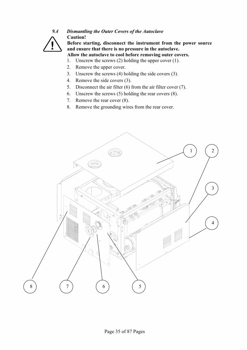
9.4 Dismantling the Outer Covers of the Autoclave Caution! Before starting, disconnect the instrument from the power source and ensure that there is no pressure in the autoclave. Allow the autoclave to cool before removing outer covers. 1. Unscrew the screws (2) holding the upper cover (1). 2. Remove the upper cover. 3. Unscrew the screws (4) holding the side covers (3). 4. Remove the side covers (3). 5. Disconnect the air filter (6) from the air filter cover (7). 6. Unscrew the screws (5) holding the rear covers (8). 7. Remove the rear cover (8). 8. Remove the grounding wires from the rear cover.
7 8
4
3
6
2 1
5

Page 36 of 87 Pages
9.5 Replacing the Safety Valve Caution! Before starting, be sure that the electric cord is disconnected and that there is no pressure in the chamber, coil or generator. Allow the autoclave to cool before removing outer covers.
The safety valve is installed to protect the system from over pressurizing
should all the electrical controls fail.
1. Take off the autoclave cover (see para. 9.3 “Removing the Autoclave’s Outer Covers”).
2. Remove the water reservoir gasket. 3. Unscrew the safety valve (2) and remove it from the safety valve
base (1). 4. Replace the valve with a new safety valve (install only an original
equipment replacement!). Use Teflon on the thread to seal it. Tighten the safety valve to prevent leaking.
5. To check the new safety valve, perform the following: 6. Turn the pressure relief nut (3) two turns counter clockwise. 7. Turn on the autoclave and perform one cycle and verify that the
valve operates correctly. 8. Turn off the autoclave, wait until the generator cools down and the
pressure decreases to atmospheric pressure. 9. Turn the pressure relief nut two turns clockwise to re-adjust the
relief pressure.
No. Description 1 Safety valve base 2 Safety valve 3 Pressure relief nut

Page 37 of 87 Pages
9.6 Replacing chamber heater Caution: Before starting, be sure that the electric cord is disconnected from the power source and that there is no pressure in the autoclave chamber.
Allow the autoclave and the steam generator to cool before removing outer covers.
7. Take off the autoclave covers (see para. 9.3 “Removing the
autoclave’s covers”). 8. Remove the insulation blanket. 9. Remove the heating element tightening bolts. 10. Disconnect the heating element wires from the porcelain
connector. 11. Replace the heating element 12. Insert the PT100 and the cut-off sensors. 13. Re-assemble the autoclave insulation and cover. 14. Tighten the fastening bolts. 15. Run a cycle and verify that it operates as required.

Page 38 of 87 Pages
9.7 Replacing steam generator heater Caution: Before starting, be sure that the electric cord is disconnected from the power source and that there is no pressure in the autoclave chamber.
Allow the autoclave and the steam generator to cool before removing outer covers.
1. Remove the autoclave cover (see para. 9.3 “Removing the autoclave’s outer covers”).
2. Drain the water from the generator by opening the drain plug. Wait until all the water has drained from the generator.
3. Disconnect the heating element wires from the porcelain connector. 4. Remove the heating element from the generator. 5. Replace the thermostat. 6. Reassemble the heating element. 7. Reassemble the autoclave’s cover. 8. Test the autoclave by performing a full cycle.

Page 39 of 87 Pages
9.8 Replacing the cut-off thermostat The autoclave is equipped with a temperature thermostat, which protects
the heaters and the autoclave against overheating, during the dry cycle. This device reconnects automatically when the chamber cools down.
Caution Before starting, disconnect the instrument from the power source and ensure that there is no pressure in the autoclave. Allow the autoclave to cool before removing outer covers.
The two temperature safety thermostats are located on the socket panel
on the rear of the autoclave.
1. Remove the rear cover (see para. 9.3 “Removing the autoclave’s outer covers”).
2. Loosen the heating band (see para. 9.5 “Replacing chamber heater”).
3. Unscrew the thermostat and replace it with a new one. 4. Perform any dry cycle to verify that the temperature safety
thermostat disconnects the heating units.
No. Description 1 Chamber heater cut-off thermostat 2 Steam generator heater cut-off thermostat
2
1

Page 40 of 87 Pages
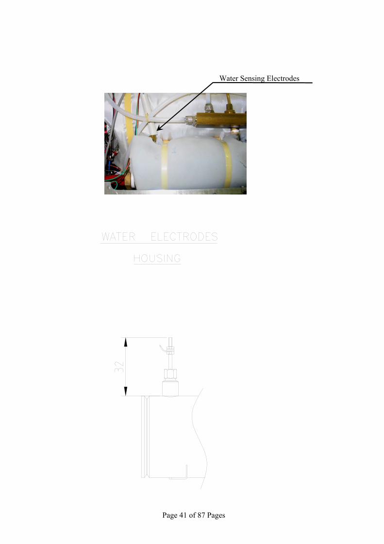
9.9 Replacing and cleaning the generator’s water level electrode The electrode that controls the water level of the generator is located in
the rear of the generator. The Electrode performs the following:
a. It protects the heating element by switching it off when there is not enough water in the generator.
b. It maintains the water level in the generator by switching the water pump on and off as required.
To clean or replace the electrode proceed as follows (refer to the picture and the drawings on the next page):
Caution! Before starting, disconnect the instrument from the power source
and ensure that there is no pressure in the chamber or the generator.
Allow the autoclave to cool before removing outer covers.
1. Take off the autoclave cover (see para. 9.3 “Removing the Autoclave’s Outer Covers”).
2. Remove the electrical connection from the terminal of the electrode.
3. Unscrew the locking nut and remove the electrode from the top of the housing.
4. Replace the electrode with a new one or reinstall the same electrode after cleaning.
4.1 To clean the electrode, use a damp cloth or sponge. A mild soapy solution may be used, rinse thoroughly. DO NOT use any harsh chemicals
4.2 When installing a new electrode, make sure that the electrode is positioned exactly as described in drawing "water level electrode (see drawing ahead).
5. Tighten the locking nut to prevent any steam or water leakage. 6. Reconnect the electrical wire to the electrode terminal. 7. Turn the autoclave on. The generator will automatically fill with
water. Observe that the unit is heating. Wait for the unit to reach 308 kPa, and then check for leaks around the locking nuts.
8. Reassemble the cover.
Page 41 of 87 Pages
Water Sensing Electrodes

Page 42 of 87 Pages
9.10 Replacing the Drain Valve There are two drain valves on the front of the autoclave. One drains the
mineral free water from the clean reservoir and the other drains the water from the waste water reservoir. Caution! Before starting, disconnect the instrument from the power source and ensure that there is no pressure in the autoclave. Allow the autoclave to cool before removing outer covers.
1. Drain the reservoir. 2. Remove the autoclave cover (see para. 9.3 “Removing the
Autoclave’s Outer Covers”). 3. Disconnect the drain tube from the valve (1). 4. Unscrew nut (6) using a 21mm socket wrench. 5. Remove the drain valve (1) from the panel (7). 6. Install a new valve and reassemble the drain tube to the drain valve. 7. Verify that there is no leakage.
7
VLV170-0013 VLV170-0015 VLV170-0014
1 6 3

Page 43 of 87 Pages
PLASTIC ELEMENTS ON THE FRONT PANEL The autoclave cover is composed with these components. For replacing
them, see the following sections.

Page 44 of 87 Pages
9.11 Replacing the Door Cover
Caution! Before starting, open the door first, then disconnect the instrument
from the power source and ensure that there is no pressure in the chamber, coil or generator.
Allow the autoclave to cool before removing outer covers.
1. Unscrew the 6 screws (1) attaching the Door Cover to the lower (3) and upper (2) cover-holders.
2. Remove the Door Cover. 3. Position the new Door Cover and screw in the 6 screws (1). 4. Turn the main power back on. 5. Close the door, select a cycle and run the autoclave. Check that
there is no steam or pressure leak around the door. If there is a leak tighten the door slightly.
No. description 1 Fastening screws 2 Upper cover-holder 3 Lower cover-holder
2
3
1
1

Page 45 of 87 Pages
9.12 Replacing the Panel Caution! Before starting, disconnect the instrument from the power source
and ensure that there is no pressure in the autoclave. Allow the autoclave to cool before replacing the Panel.
1. Open the printer's door (4). 2. Unscrew the three bottom fastening screws (5). 3. Unscrew the top fastening screw (1). 4. Pull the panel approx. 30 centimeters. 5. Remove the digital card (located on the rear side of the panel). 6. Remove the printer (3) (see sec. 9.15 "Replacing the Printer"). 7. Assemble the digital card on the new panel. 8. Assemble the printer on the new panel. 9. Assemble the panel and fasten it to the autoclave with the 4
fastening screws (1 & 5).
3
2
4
1
5
Page 46 of 87 Pages
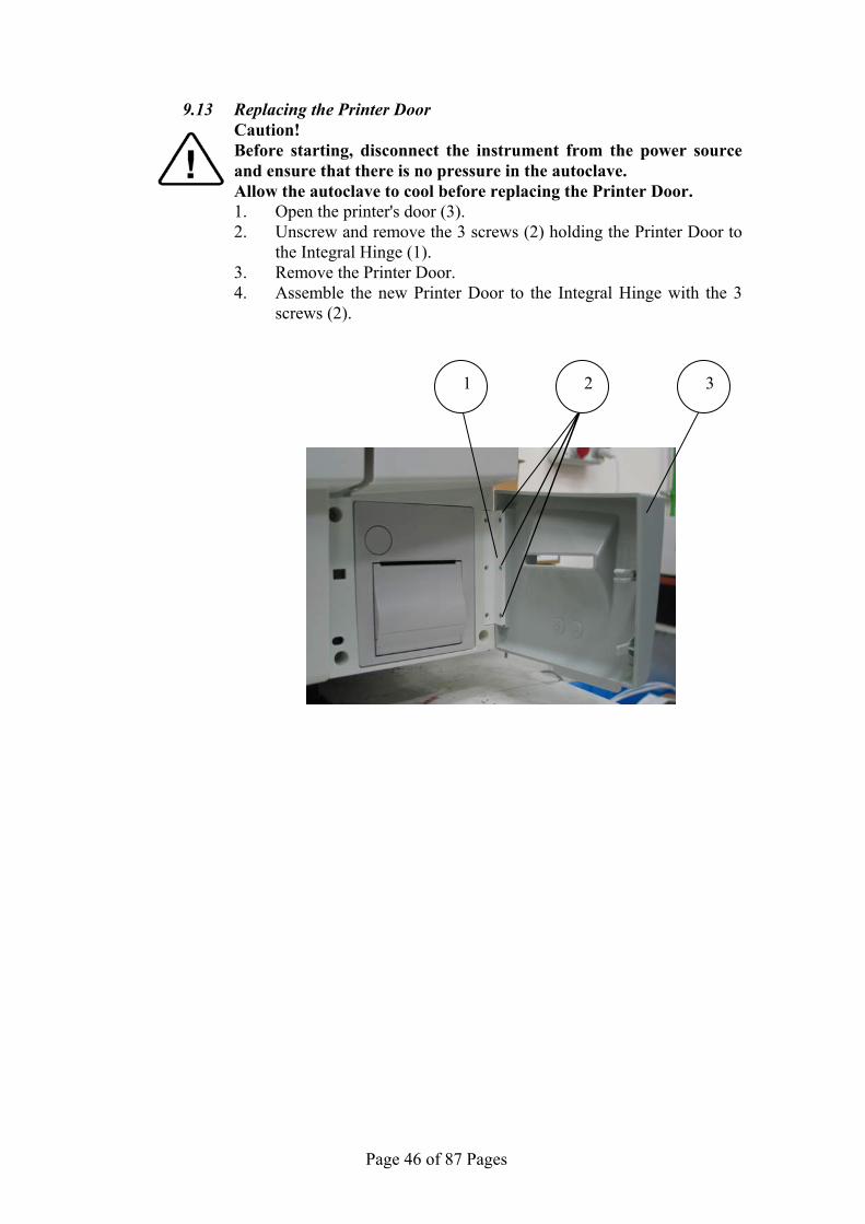
9.13 Replacing the Printer Door Caution! Before starting, disconnect the instrument from the power source
and ensure that there is no pressure in the autoclave. Allow the autoclave to cool before replacing the Printer Door.
1. Open the printer's door (3). 2. Unscrew and remove the 3 screws (2) holding the Printer Door to
the Integral Hinge (1). 3. Remove the Printer Door. 4. Assemble the new Printer Door to the Integral Hinge with the 3
screws (2).
3 1 2
Page 47 of 87 Pages
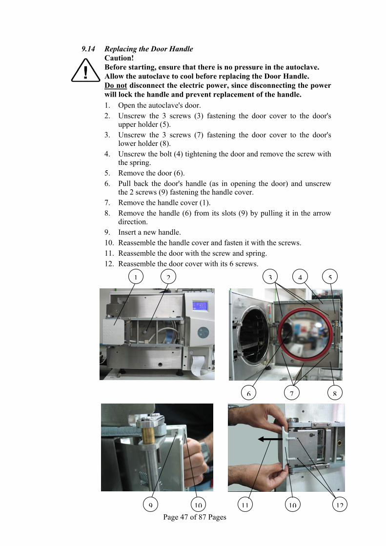
9.14 Replacing the Door Handle Caution! Before starting, ensure that there is no pressure in the autoclave. Allow the autoclave to cool before replacing the Door Handle. Do not disconnect the electric power, since disconnecting the power
will lock the handle and prevent replacement of the handle.
1. Open the autoclave's door. 2. Unscrew the 3 screws (3) fastening the door cover to the door's
upper holder (5). 3. Unscrew the 3 screws (7) fastening the door cover to the door's
lower holder (8). 4. Unscrew the bolt (4) tightening the door and remove the screw with
the spring. 5. Remove the door (6). 6. Pull back the door's handle (as in opening the door) and unscrew
the 2 screws (9) fastening the handle cover. 7. Remove the handle cover (1). 8. Remove the handle (6) from its slots (9) by pulling it in the arrow
direction. 9. Insert a new handle. 10. Reassemble the handle cover and fasten it with the screws. 11. Reassemble the door with the screw and spring. 12. Reassemble the door cover with its 6 screws.
10
1 2 43
7
11 12
6 8
9 10
5

Page 48 of 87 Pages
9.15 Replacing the Plastic Handle Cover Caution! Before starting, ensure that there is no pressure in the autoclave. Allow the autoclave to cool before replacing the Door Handle. Do not disconnect the electric power, since disconnecting the power
will lock the handle and prevent replacement of the handle.
1. Open the autoclave's door. 2. Unscrew the 3 screws (3) fastening the door cover to the door's
upper holder (5). 3. Unscrew the 3 screws (7) fastening the door cover to the door's
lower holder (8). 4. Unscrew the bolt (4) tightening the door and remove the screw with
the spring. 5. Remove the door (6). 6. Pull back the door's handle (as in opening the door) and unscrew
the 2 screws (9) fastening the handle cover. 7. Remove the handle cover (8). 8. Assemble the new handle cover and fasten it with the screws. 9. Reassemble the door with the screw and spring. 10. Reassemble the door cover with its 6 screws.
1 2 43
76 8
9 10
5
Page 49 of 87 Pages
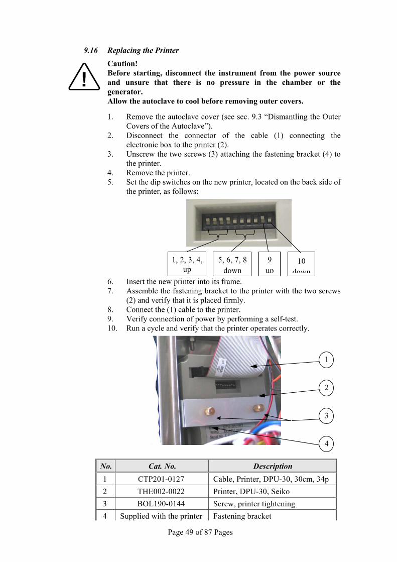
9.16 Replacing the Printer
Caution! Before starting, disconnect the instrument from the power source
and unsure that there is no pressure in the chamber or the generator.
Allow the autoclave to cool before removing outer covers.
1. Remove the autoclave cover (see sec. 9.3 “Dismantling the Outer Covers of the Autoclave”).
2. Disconnect the connector of the cable (1) connecting the electronic box to the printer (2).
3. Unscrew the two screws (3) attaching the fastening bracket (4) to the printer.
4. Remove the printer. 5. Set the dip switches on the new printer, located on the back side of
the printer, as follows:
6. Insert the new printer into its frame. 7. Assemble the fastening bracket to the printer with the two screws
(2) and verify that it is placed firmly. 8. Connect the (1) cable to the printer. 9. Verify connection of power by performing a self-test. 10. Run a cycle and verify that the printer operates correctly.
1
3
2
4
No. Cat. No. Description 1 CTP201-0127 Cable, Printer, DPU-30, 30cm, 34p 2 THE002-0022 Printer, DPU-30, Seiko 3 BOL190-0144 Screw, printer tightening 4 Supplied with the printer Fastening bracket
5, 6, 7, 8 down
1, 2, 3, 4,up
9 up
10 down

Page 50 of 87 Pages
9.17 Replacing the Door Switch
Caution! Before starting, disconnect the instrument from the power source
and verify that there is no pressure in the chamber or the generator. Allow the autoclave to cool before removing outer covers.
1. Remove the autoclave top and left covers (see para. 9.3 “Dismantling the Outer Covers of the Autoclave”).
2. Open the door 3. Unscrew the 2 screws (1) holding the door switch adapter (4) on
the front panel of the autoclave. 4. Disconnect the 2 wires (3) from the door switch (2). 5. Remove the door switch from the autoclave. 6. Unscrew the door switch (2) from the door switch adapter (4). 7. Assemble the new door switch to the adapter. 8. Reconnect the 2 wires (3) to the door switch. Verify that the green
wire is connected to screw no. 1 (marked on the switch) and the red wire is connected to screw no. 3 (marked on the switch).
9. Reassemble the door switch with its adapter to the front panel.
Make sure that the door switch is installed correctly! Check that the operational message “Door is Open" is
displayed when the door is opened and that the message disappears when the door is closed.
1 2
4
3 4
2

Page 51 of 87 Pages
9.18 Replacing the fuse on the Electronic Board Caution! Before starting, disconnect the instrument from the power source.
There are 3 fuses on the AC card: 1. fuse 3.15 A FAST to the chamber heater 2. fuse 2A FAST to the vacuum pump 3. fuse 2A FAST to the water pump
To replace the fuses operate as following: 6. Disconnect the keyboard panel from the autoclave (see sec. 9.11 "
Replacing the Panel"). 7. Pull it outwards as far as possible. 8. With a small screwdriver disconnect the fuse holder (2) from the
board (1). 9. Remove the faulty fuse (6) from the holder and replace it with a
new one. 10. Return the fuse holder with the new fuse to the board. 11. Reassemble the panel.
4 5 3
6
2
1
2
Page 52 of 87 Pages
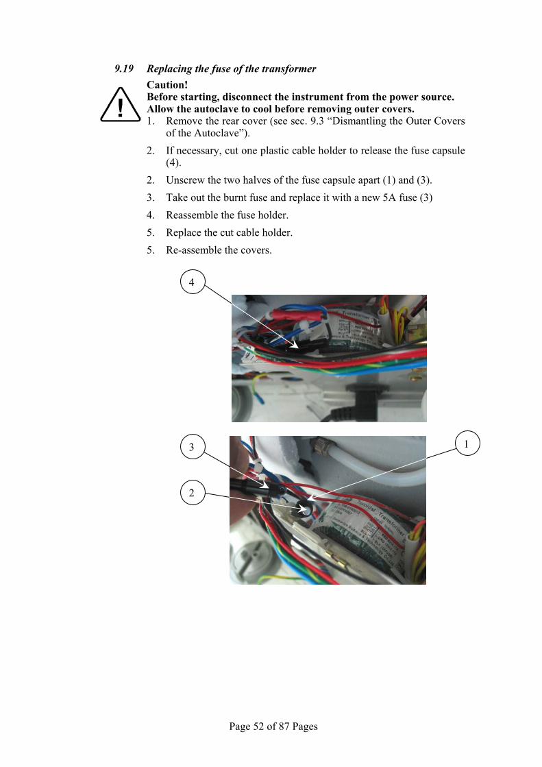
9.19 Replacing the fuse of the transformer
Caution! Before starting, disconnect the instrument from the power source. Allow the autoclave to cool before removing outer covers.
1. Remove the rear cover (see sec. 9.3 “Dismantling the Outer Covers of the Autoclave”).
2. If necessary, cut one plastic cable holder to release the fuse capsule (4).
2. Unscrew the two halves of the fuse capsule apart (1) and (3). 3. Take out the burnt fuse and replace it with a new 5A fuse (3) 4. Reassemble the fuse holder. 5. Replace the cut cable holder. 5. Re-assemble the covers.
3
2
1
4

Page 53 of 87 Pages
72
1
3
6
4
5
•
9.20 Replacing the water pump 1. Empty the water reservoir. 2. Remove the autoclave rear cover (see sec. 9.3 “Dismantling the
Outer Covers of the Autoclave”). 3. Disassemble the electrical socket bracket. 4. Disconnect the wires from the pump. 5. Disconnect the piping from the pump. 6. Remove the pump from the rubber shock absorbers.
If the rubber shock absorbers are damaged, replace them. 7. Replace the damaged pump with a new pump. 8. Reconnect wiring and piping. 9. Reassemble the electrical socket bracket. 10. Reassemble the rear cover. 11. Turn on the autoclave and verify it operates correctly.
No. Description Cat. No.
1 Rubber shock absorber SKR203-0006 2 Fitting 5/16”x1/8” (straight) 3 Screw BOL191-0140 4 Nut NUT192-0191 5 washer NUT193-0250 6 Spring washer NUT193-0315 7 ULKA water pump PUM055-0021

Page 54 of 87 Pages
9.21 Replacing the vacuum pump
Caution! Before starting, disconnect the instrument from the power source and
ensure that there is no pressure in the chamber, coil or steam generator.
Allow the autoclave to cool before removing outer covers.
1. Take off the autoclave cover (see para. 9.3 “Dismantling the Outer Covers of the Autoclave”).
2. Disconnect the electrical wires (blue and brown wires) (3). 3. Disconnect the inlet tube (1) and outlet tube (4). 4. Unscrew the 4 pump-legs screws (2). 5. Remove the vacuum pump. 6. Install a new pump and assemble the leg screws (2). 7. Install tubes (1) & (4). Use Teflon tape to prevent leakage. 8. Connect the electrical wires. Verify that the wires are connected in
the right way. 9. Reassemble the covers. 10. Connect the autoclave to the power supply and turn on the
autoclave. Perform a leakage test and verify that the vacuum pump operates O.K.
3
1
42

Page 55 of 87 Pages
9.22 Replacing the Plunger or Coil of the 1/4" Solenoid Valve The solenoid valves may be out of order due to faulty plunger or coil.
To repair the solenoid valve – replace the faulty plunger or solenoid Caution! Before starting, disconnect the instrument from the power source
and ensure that there is no pressure in the chamber. Allow the autoclave to cool before removing outer covers.
1. Take off the autoclave top cover (see para. 9.3 “Removing the
Autoclave’s Outer Covers”). 2. Remove nut (1). 3. Remove the coil (2). 4. Unscrew the plunger + spring (3) with the plunger housing (4) and
replace it with a new one. The plunger and the spring are replaced as a kit.
5. Reassemble the coil (2) and the nut (1). 6. Re-install the autoclave’s cover.
3 4
2
1

Page 56 of 87 Pages
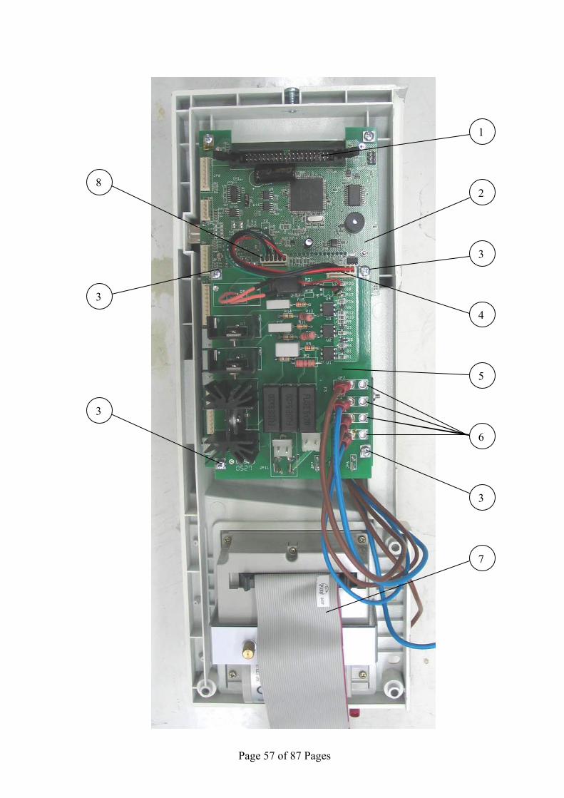
9.23 Replacing the Electronic Boards Caution! Before starting, disconnect the instrument from the power source
and ensure that there is no pressure in the chamber. Allow the autoclave to cool before removing outer covers. See drawings of "Nova4-D2N" and "Nova4-A1 to assist in locating
connectors marked by JP 1. Take off the autoclave top cover (see para. 9.3 “Removing the
Autoclave’s Outer Covers”). 2. Disconnect the control panel (see para. 9.11 "Replacing the
Panel"). 3. Disconnect all the wires from the control boards (2 & 5). Verify
that the wires arte numbered according to the connector's numbers.
4. Disconnect the flat cable (7) from flat cable socket on the big board (2).
5. Remove the panel from the autoclave and place it on a table with the keyboard downwards.
9.23.1 Replacing the "Nova4-A1" (small) board
1. Disconnect wires from JP2, JP3, JP4, JP5 (6). 2. Disconnect connector JP10 (4). 3. Unscrew the 4 screws (3) attaching the small board (5)
to the big board (2). 4. Remove the small board. 5. Check the isolation sheet that is placed under the board.
Replace if damaged. 6. Place the new board and fasten it with the 4 screws (3). 7. Connect the wires to JP10, JP2-JP5. 8. Return the control unit to the autoclave and reconnect
the wires. Be aware to the wires numbering, they fit the JP numbers on the board.
9. Re-assemble the control panel to the autoclave Caution! Before starting, disconnect the instrument from the power source
and ensure that there is no pressure in the chamber. Allow the autoclave to cool before removing outer covers.
Page 57 of 87 Pages
1
2
3
4
5
3
6
3
3
7
8

Page 58 of 87 Pages
Nova4-A1 Board
JP2
JP11 JP9 JP7 JP8
JP3
JP4
JP5
JP6
JP10

Page 59 of 87 Pages
Nova4-D2N Board
JP4 JP8
JP3
JP6
JP12
JP13
JP15
JP1
JP11
JP2
JP9
JP5
Page 60 of 87 Pages
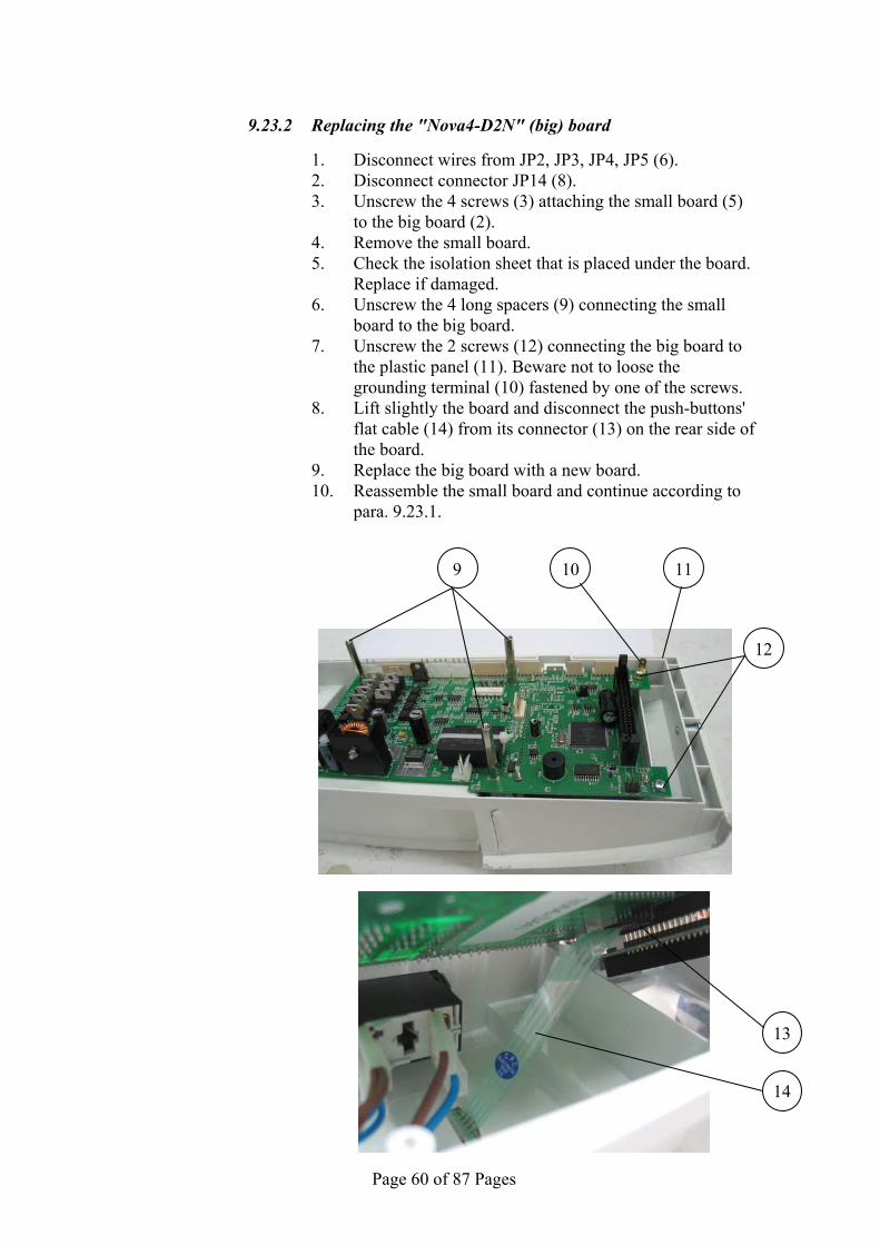
9.23.2 Replacing the "Nova4-D2N" (big) board
1. Disconnect wires from JP2, JP3, JP4, JP5 (6). 2. Disconnect connector JP14 (8). 3. Unscrew the 4 screws (3) attaching the small board (5)
to the big board (2). 4. Remove the small board. 5. Check the isolation sheet that is placed under the board.
Replace if damaged. 6. Unscrew the 4 long spacers (9) connecting the small
board to the big board. 7. Unscrew the 2 screws (12) connecting the big board to
the plastic panel (11). Beware not to loose the grounding terminal (10) fastened by one of the screws.
8. Lift slightly the board and disconnect the push-buttons' flat cable (14) from its connector (13) on the rear side of the board.
9. Replace the big board with a new board. 10. Reassemble the small board and continue according to
para. 9.23.1.
13
14
9
12
10 11

Page 61 of 87 Pages
9.24 Replacing the switch Caution! Before starting, disconnect the instrument from the power source
and ensure that there is no pressure in the chamber. Allow the autoclave to cool before removing outer covers.
1. Remove the control electronic boards (see para. 9.22 "Replacing the Electronic Boards").
2. Disconnect the wires (1) from the switch (3). Log which wire is connected to each leg (2) of the switch.
3. Press the switch's fasteners (5) and push the switch inwards to release it from its seat on the panel (4).
4. Remove the switch and replace it with a new one. Pay attention to the switch's position. The "0" on the switch must be opposite the "0" in the plastic panel and the "|" on the switch must be opposite the "|" on the panel.
5. Connect the wires to the switch. Verify that the number on the wires match those on the switch.
6. Place the big board on the panel ad reconnect the pushbutton's flat cable to the board.
7. Reassemble the electronic boards according to para. 9.22.
21
3
4
5

Page 62 of 87 Pages
9.25 Draining the generator Caution! Before starting, disconnect the instrument from the power source
and ensure that there is no pressure in the generator. Allow the autoclave to cool before draining the generator.
1. Move the autoclave aside and reveal the generator's drain plug (1).
It is placed on the left bottom side of the autoclave. 2. Place a vessel under the autoclave to collect the drain water. 3. Unscrew the drain plug, using a 3/17 allen spanner. 4. After draining the water, reassemble the drain plug. 5. Move the autoclave back to its leveled position, reconnect it to the
power source and turn the autoclave on. 6. Check and verify that the generator is filled with water and that the
plug does not leak.
1

Page 63 of 87 Pages
9.26 Emergency Door Opening Caution! Before starting, disconnect the instrument from the power source and ensure that there is no pressure in the autoclave.
9.26.1 Decreasing the pressure Since the autoclave is not equipped with an analogue pressure
gauge, and the display is off (no electrical power), it is recommended to wait approximately one hour to verify that the pressure and temperature have decreased to ambient conditions.
If it is required to open the door urgently, decrease the pressure by opening both, the chamber's and generator's safety valves as follows. The safety valves are located in the mineral-free water reservoir.
A. ASME-approved type safety valve
1. Remove water reservoir cover (1). 2. Pull the ring (4) of the safety valve using a tool, i.e.
screwdriver, hook etc. (3). Pull the safety valve ring until steam ceases to escape from the safety valve. Be careful not to burn your hands.
2 4 3
No. Description 1 water reservoir cover 2 Safety valve 3 Pulling device 4 Pressure relief ring
1
Page 64 of 87 Pages
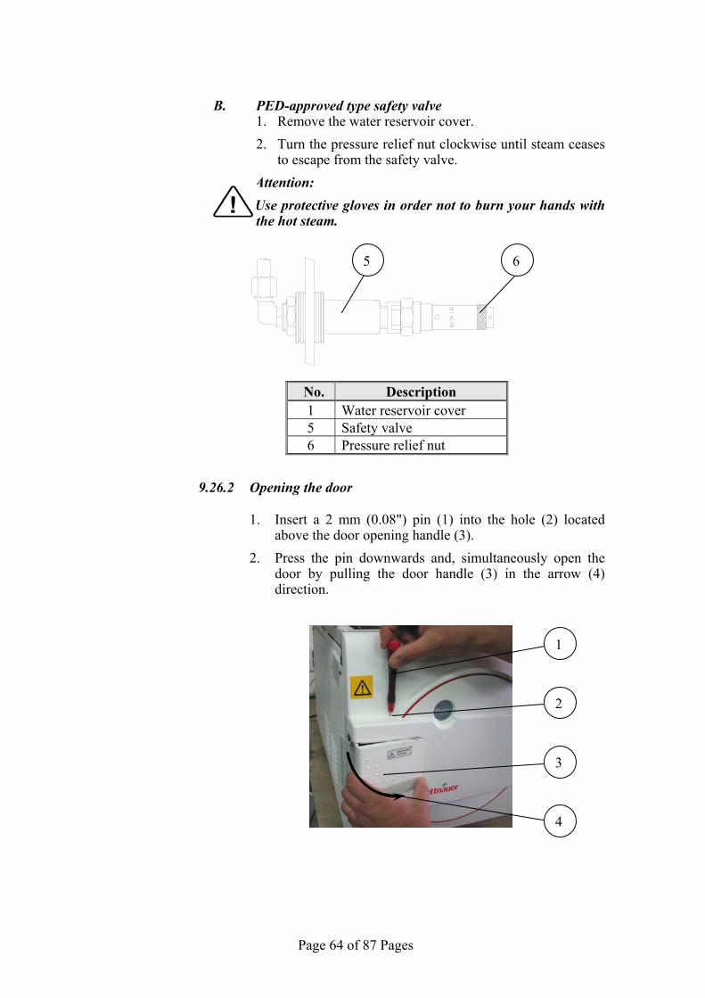
B. PED-approved type safety valve
1. Remove the water reservoir cover. 2. Turn the pressure relief nut clockwise until steam ceases
to escape from the safety valve. Attention: Use protective gloves in order not to burn your hands with the hot steam.
9.26.2 Opening the door
1. Insert a 2 mm (0.08") pin (1) into the hole (2) located
above the door opening handle (3). 2. Press the pin downwards and, simultaneously open the
door by pulling the door handle (3) in the arrow (4) direction.
No. Description 1 Water reservoir cover 5 Safety valve 6 Pressure relief nut
5 6
1
2
4
3

Page 65 of 87 Pages
9.27 Cleaning and replacing the water reservoirs
Caution! Before starting, disconnect the instrument from the power source and ensure that there is no pressure in the autoclave.
Note: The following instructions refer to both, the mineral-free water
reservoir and to the waste-water reservoir.
5
5
55
3
6
3
4
4 5
AB
1
2
1

Page 66 of 87 Pages
1. Drain the water reservoir. 2. Remove the right, rear and top covers of the autoclave (see para.
9.4 "Dismantling the Outer Covers of the Autoclave"). 3. Unscrew screws (3) and remove the right top frame (6). 4. Unscrew screws (1) and loosen the rear top frame (2). 5. Disconnect the cable terminals (4) from the water level electrodes. 6. Cut the tie wraps fastening the flexible tubs (5) to the water
reservoir. 7. Disconnect the tubes from the water reservoir. 8. To replace or clean the mineral-free water reservoir, Pull the rear
top frame slightly backward (A). 9. Pull the reservoir upward (B), out of the autoclave. 10. Clean or replace the reservoir as required. 11. Insert the new or clean reservoir into the autoclave. 12. Assemble the water tubes (do not forget to fasten the required
tubes with tie wraps (5). 13. Connect the cable terminals (4) to the water level electrodes. 14. Re-assemble the right and rear frames. 15. Re-assemble the right rear and top covers.
Page 67 of 87 Pages
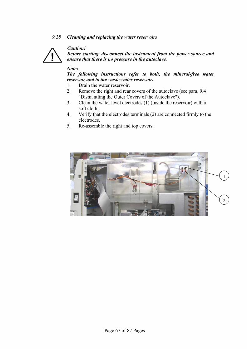
9.28 Cleaning and replacing the water reservoirs
Caution! Before starting, disconnect the instrument from the power source and ensure that there is no pressure in the autoclave.
Note: The following instructions refer to both, the mineral-free water
reservoir and to the waste-water reservoir. 1. Drain the water reservoir. 2. Remove the right and rear covers of the autoclave (see para. 9.4
"Dismantling the Outer Covers of the Autoclave"). 3. Clean the water level electrodes (1) (inside the reservoir) with a
soft cloth. 4. Verify that the electrodes terminals (2) are connected firmly to the
electrodes. 5. Re-assemble the right and top covers.
1
2
Page 68 of 87 Pages
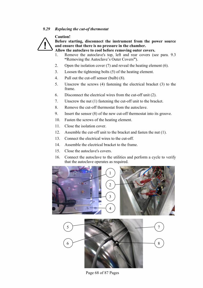
9.29 Replacing the cut-of thermostat Caution! Before starting, disconnect the instrument from the power source
and ensure that there is no pressure in the chamber. Allow the autoclave to cool before removing outer covers.
1. Remove the autoclave's top, left and rear covers (see para. 9.3 “Removing the Autoclave’s Outer Covers”).
2. Open the isolation cover (7) and reveal the heating element (6). 3. Loosen the tightening bolts (5) of the heating element. 4. Pull out the cut-off sensor (bulb) (8). 5. Unscrew the screws (4) fastening the electrical bracket (3) to the
frame. 6. Disconnect the electrical wires from the cut-off unit (2). 7. Unscrew the nut (1) fastening the cut-off unit to the bracket. 8. Remove the cut-off thermostat from the autoclave. 9. Insert the sensor (8) of the new cut-off thermostat into its groove. 10. Fasten the screws of the heating element. 11. Close the isolation cover. 12. Assemble the cut-off unit to the bracket and fasten the nut (1). 13. Connect the electrical wires to the cut-off. 14. Assemble the electrical bracket to the frame. 15. Close the autoclave's covers. 16. Connect the autoclave to the utilities and perform a cycle to verify
that the autoclave operates as required.
6
5 7
8
1
2
3
4

Page 69 of 87 Pages
9.30 Replacing the PT100 of the chamber's heating element Caution! Before starting, disconnect the instrument from the power source
and ensure that there is no pressure in the chamber. Allow the autoclave to cool before removing outer covers.
1. Remove the autoclave's top and right covers (see para. 9.3 “Removing the Autoclave’s Outer Covers”).
2. Open the isolation cover (5) and reveal the heating element (2). 3. Loosen the tightening bolts (1) of the heating element. 4. Pull out the PT100 sensor (3). 5. Disconnect the PT100 wire (4) from the board. 6. Remove the temperature sensor from the autoclave. 7. Insert the sensor of the PT100 into its groove. 8. Fasten the screws of the heating element. 9. Close the isolation cover. 10. Connect the PT100 wire to the board. 11. Close the autoclave's covers.
2
3
4
51

Page 70 of 87 Pages
9.31 Replacing the pressure transducer
Caution! Before starting, disconnect the instrument from the power source and ensure that there is no pressure in the autoclave and in the generator.
Note: The following instructions refer to both, the chamber and the generator
pressure transducer.
1. Remove the top cover (see para. 9.3 “Removing the Autoclave’s Outer Covers”).
2. Lift slightly the pressure transducer (1) as in picture 1. 3. Unscrew screw (2). 4. Remove the connector (3) as in picture 2. 5. Unscrew the pressure transducer. Use two open spanners (5) as
shown in picture 3. 6. Remove the pressure transducer and replace it with a new one. 7. Fasten the new pressure transducer. Use two spanners as in picture 3. 8. Assemble the connector (3) and fasten it with the screw (2).push
down the pressure transducer to its place, below the front panel top (4).
Picture 1 Picture 2 Picture 3
5 4 3 2 5 1

Page 71 of 87 Pages
10 TROUBLESHOOTING
10.1 Preliminary Check
NOTE! Most of the autoclave's malfunctions result from dirt. Before performing troubleshooting at the customer location we
recommend to follow the procedure described bellow: o Disconnect the autoclave from the electric power source. o Remove the covers. o Clean the trays and the trays holder. o Clean the filters. o Remove the plungers of the solenoid and clean the solenoid base.
Replace plungers if required. o Inspect that there are no sign of water leaks or sediments. o Inspect and make sure that there are no sign of electric loose
connections. o Tighten all the loose screws, nuts and piping connections.

Page 72 of 87 Pages
10.2 Troubleshooting procedure
Symptom Possible cause check-up and tests Corrections
Main switch is off. Turn main switch on. Make sure that there is power source according to the utilities.Make sure that the power cord is not damaged and that it is connected well. The power, electrical power
cord or the connections at the autoclave input are faulty. If the safety circuit breaker
shuts off the power make sure that there are no sign of water. Make sure that there are no un-isolated wires.
One of the Cut-off thermostats tripped.
Reset cut-off thermostat.
One of the Cut-off thermostats is faulty.
Replace the faulty cut-off thermostat.
One of the fuses of the transformer burnt.
Replace the burnt fuse.
Transformer is faulty. Replace the transformer. Main switch is faulty. Replace the main switch.
No light in the display
Electrical wiring loose or making short-circuit.
Find the loosing wire or connector.
Symptom Possible cause check-up and tests Corrections
PT100 No. 1 of the chamber is disconnected. Reconnect the PT100.
PT100 No. 1 of the chamber is faulty. Replace chamber’s PT100.
Err:001 is displayed
PT1 out
AC board is faulty. Replace the faulty AC board.
Symptom Possible cause check-up and tests Corrections
Electrical supply disconnected
Fix electrical supply to the heating elements. Heating
elements do not heat. Faulty heating
elements. Replace faulty heating elements.
Err:002 is displayed
Low Temperature
Not sufficient water introduce to the generator. The electrode does detect water and the control system does not activate the heater. Can be a resulted of blockage in the piping between the clean water reservoir to the steam generator, faulty water pump or faulty check valve.
Follow the piping diagram and check if there is blockage in piping. Release and clean the manifold.Replace faulty parts – check steam inlet valve and piping from the generator to the chamber.

Page 73 of 87 Pages
Symptom Possible cause check-up and tests Corrections
Not calibrated. Calibrate the chamber’s temperature sensor.
Low Temperature (cont.)
Chamber’s temperature sensor is: Faulty.
Replace the chamber’s temperature sensor.
Err:002 is displayed (cont.)
Dirt or sediments in the steam generator or faulty heaters.
Take out the steam generator clean the sediments or replace the faulty heaters.
Symptom Possible cause check-up and tests Corrections
Chamber’s temperature sensor is not calibrated.
Calibrate the chamber’s temperature sensor. Err:003 is
displayed High Temperature Chamber’s temperature sensor
is faulty. Replace the chamber’s temperature sensor.
Symptom Possible cause check-up and tests Corrections
High Gen Press
Generator’s pressure sensor is not calibrated.
Calibrate the generator’s pressure sensor.
In the pressure switch.
Replace the faulty pressure switch.
Err:005 is displayed
The heater in the generator does not stop heating as a result of a problem:
In the AC board. Replace the faulty AC board
Symptom Possible cause
check-up and tests Corrections
Steam to chamber valve does not close as a resulted of dirty of faulty plunger.
Fix or replace the faulty valve.
Chamber’s pressure sensor is not calibrated.
Open the autoclave’s door and read pressure on the display. If reading is not accurate (atmospheric pressure), calibrate the chamber’s pressure sensor.
Err:007 is displayed
High pressure
Chamber’s pressure sensor is faulty.
If calibration did not solve the problem the chamber’s pressure sensor is faulty, replace it.

Page 74 of 87 Pages
Symptom Possible cause check-up and tests Corrections
Door seal is dirty or faulty. Clean or replace door seal. Piping is leaking. Fix the leaking point. Air valve is leaking. Fix or replace the valve. Exhaust valve is leaking. Fix or replace the valve. Vacuum valve is leaking. Fix or replace the valve. Steam valve is leaking. Fix or replace the valve.
Safety valve is leaking. Close Pressure Relief Nut or replace the valve.
Chamber’s pressure sensor is not calibrated.
If calibration did not solve the problem the chamber’s pressure sensor is faulty. Replace the sensor.
Chamber’s pressure sensor is faulty. Replace the pressure sensor.
Generator’s pressure sensor is not calibrated.
Calibrate the generator’s pressure sensor.
Err:008 is displayed
Low Pressure
Generator’s pressure sensor is faulty.
If calibration did not solve the problem the generator’s pressure sensor is faulty, replace it.
Symptom Possible cause check-up and tests Corrections
Err:009 is displayed
System Error This message displayed if the real time clock is faulty. Replace the main board.
Symptom Possible cause check-up and tests Corrections
Err:011 is displayed Door is
Open
The error is displayed despite that the door is closed. The door switch is faulty.
Adjust or replace the door switch.
Symptom Possible cause check-up and tests Corrections
Err:012 is displayed
Manual Stop
The START/STOP key was pressed and the cycle is aborted.
Press the START/STOP key to delete the error message. To open the door, wait until the pressure decreases to ambient pressure.
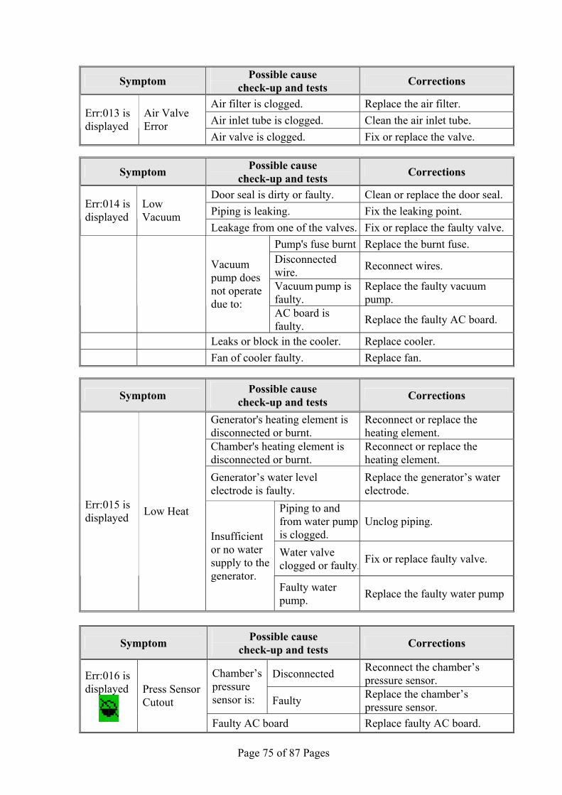
Page 75 of 87 Pages
Symptom Possible cause check-up and tests Corrections
Air filter is clogged. Replace the air filter. Air inlet tube is clogged. Clean the air inlet tube. Err:013 is
displayed Air Valve Error
Air valve is clogged. Fix or replace the valve.
Symptom Possible cause check-up and tests Corrections
Door seal is dirty or faulty. Clean or replace the door seal. Piping is leaking. Fix the leaking point. Err:014 is
displayed Low Vacuum
Leakage from one of the valves. Fix or replace the faulty valve. Pump's fuse burnt Replace the burnt fuse. Disconnected wire. Reconnect wires.
Vacuum pump is faulty.
Replace the faulty vacuum pump.
Vacuum pump does not operate due to:
AC board is faulty. Replace the faulty AC board.
Leaks or block in the cooler. Replace cooler. Fan of cooler faulty. Replace fan.
Symptom Possible cause check-up and tests Corrections
Generator's heating element is disconnected or burnt.
Reconnect or replace the heating element.
Chamber's heating element is disconnected or burnt.
Reconnect or replace the heating element.
Generator’s water level electrode is faulty.
Replace the generator’s water electrode.
Piping to and from water pump is clogged.
Unclog piping.
Water valve clogged or faulty.
Fix or replace faulty valve.
Err:015 is displayed Low Heat
Insufficient or no water supply to the generator.
Faulty water pump. Replace the faulty water pump
Symptom Possible cause check-up and tests Corrections
Disconnected Reconnect the chamber’s pressure sensor. Chamber’s
pressure sensor is: Faulty Replace the chamber’s
pressure sensor.
Err:016 is displayed
Press Sensor Cutout
Faulty AC board Replace faulty AC board.

Page 76 of 87 Pages
Symptom Possible cause check-up and tests Corrections
Disconnected Reconnect the chamber's wall PT100.
Chamber's wall temperature sensor is: Faulty Replace the chamber's wall
PT100.
Err:017 is displayed
Pt2 out
Faulty AC board Replace faulty AC board.
Symptom Possible cause check-up and tests Corrections
Err:018 Press Sensor Cutout
Generator’s pressure sensor is disconnected or out of range.
Reconnect or replace the generator’s pressure sensor.
Symptom Possible cause check-up and tests Corrections
Generator’s piping leaks. Locate and fix the leaking point.
Water pump is faulty. Replace water pump. Err:020 is displayed
No Gen water
Generator’s water sensor is faulty.
Clean Replace the generator’s water level electrode.
Symptom Possible cause check-up and tests Corrections
Door seal is dirty or faulty. Clean or replace the door seal. Err:021 is displayed
Vacuum Test Fail Piping is leaking. Fix the leaking point.
Symptom Possible cause check-up and tests Corrections
Mineral free water reservoir is empty.
Pour mineral-free water in the front funnel until it reaches the "full" level.
This symbol is displayed
No water The symbol appears despite that the reservoir is full: water level electrodes are disconnected, dirty or faulty.
Fix, clean or replace water level electrodes in the mineral-free water reservoir.
Symptom Possible cause check-up and tests Corrections
The two water level electrodes may be connected with dirt,
Clean water level electrodes in the mineral-free water reservoir.
Mineral free water reservoir is empty but "no water" symbol does not appear.
The water level electrodes may be short-circuited.
Locate and Fix the short circuit.

Page 77 of 87 Pages
Symptom Possible cause check-up and tests Corrections
The waste water reservoir is full.
Empty the waste water reservoir.
This symbol is displayed
Remove water
The symbol appears despite that the reservoir is empty: water level electrodes are dirty, disconnected or faulty.
Fix, clean or replace water level electrodes of the waste water reservoir.
Symptom Possible cause check-up and tests Corrections
The autoclave is preheating (not ready).
Wait for the autoclave to reach the proper operating conditions for starting a new cycle.
Disconnected
Reconnect the chamber's wall PT100.
Not calibrated Calibrate the chamber's wall PT100.
Chamber's wall temperature sensor is:
Faulty Replace the chamber's wall PT100.
This symbol is displayed
Low Chamber wall Temp
Chamber's wall temperature sensor is faulty.
Replace the chamber's wall temperature sensor.
Symptom Possible cause check-up and tests Corrections
The autoclave is not powered. Turn-on the autoclave.
The locking solenoid is disconnected. Fix electrical wires.
Door does not open
The locking solenoid is faulty. Replace the locking solenoid.

Page 78 of 87 Pages
11 LIST OF SPARE PARTS
R Part No. Description ACS215-0008 Pouch rack ARM067-0022 Cap, Plastic, Black, 32mm ARM100-0152 Heat Exchanger, 15/04x10x0127/16, Lordan 1 ARM172-0007 Check Valve, Spring Disk, 1/4", St.St., Mondeo CLE096-0020 Cleaning Powder, Chamber Brite, 1 Packet CLE096-0026 Cleaning Powder, Chamber Brite, 1 Box CMT240-0002 Handle, Tray, TTA 1730, 2340, 2540 CMT411-0072 Reservoir, mineral free water, assembly, ELARA CMT411-0073 Reservoir, waste water, assembly, ELARA COV411-0001 Cover, Chamber Isolation, ELARA 11 COV411-0002 Cover, Right, ELARA 11 COV411-0003 Cover, Top, ELARA 11 COV411-0004 Cover, Left, ELARA 11 COV411-0006 Cover, Rear, ELARA 11 CPN064-0031 Keyboard 1 CTP200-0103 Control Unit, Electronic, Elara 1 CTP201-0137 Fan, Axial, 24VAC, 80mm, PM8025HA24B-7, Pelko Motors 1 CTP201-0159 Fan, 230VAC, 38*150*172, 5915PC-23T-B30-A00, NMB-MAT CTP201-0164 Board, Electronic, Main, NOVA4-DN2, Elara CTP201-0165 Board, Electronic, AC, NOVA4-A1 CTP201-0174 Cable, Flat, for Printer, 50cm, 40P 1 ELC258-0003 Sensor, Temperature, PT100, 5*60, 3 Wires, Assy. ELC411-0003 Harness, electrical, ELARA 5 ELE035-0009 Fuse, Mini, Slow Blow, 2A, 5*20 5 ELE035-0075 Fuse, Mini, Fast Blow, 5A, 5*20
1 ELE035-0090 Fuse, Slow Blow, Glass Tube, 0.5A, 250V, 5*20, 0034.5614, Schurter
1 ELE035-0092 Transformer, 2x115 / 2x12, 50/60 hz, TDB-100, Jishisheng 1 ELE035-0102 Circuit Breaker, 2Pole, 15A, TA45-ABOWM150C0, White, Schurter5 ELE035-0128 Fuse, Glass Tube, 3.15A, 250V, 5*20, 179020, Siba
1 ELE036-0026 Microswitch, Heavy Duty, Snap Action, 20A, 250VAC, 2HP, GPTBRH11, CHEERY
ELE039-0084 Cable Tie, Nylon, 1168mm, YJ-1168, Kang Yang FIL175-0020 Filter, Water, PVC 1 FIL175-0042 Filter, Air, 0.2 Micron, Model 50mm D FIL175-0060 Strainer, 40 mesh, St.St., w/Grip FIL175-0069 Fan guard, 170 mm, NiCr plated, FGW-162A-5, Cooltron 1 GAS080-0007 Gasket, Silicone, Water Reservoir 1 GAS080-0040 Gasket, Mineral-Free Water Reservoir, ELARA

Page 79 of 87 Pages
R Part No. Description 1 GAS080-0055 Gasket, Door, Silicon, ELARA 1 GAS084-0007 Tube, drain, 13x10, Silicon HEA010-0017 Heating Element, 230V, 500W 12*11 M/E 1 HEA016-0031 Heating Element, 230V, 1" NPT*300, 2*1100W, Nova3, Generator INS077-0020 Isolation sheet, electronic board, ELARA LOK254-0001 Washer, locking solenoid pin, 1730, 2340, 2540 LOK411-0018 Washer, locking solenoid pin, ELARA PIP411-0002 Coil, cooling, ELARA PNE195-0040 Silencer 1/4", SFE 140, Sistem Pneumatica POL065-0041 Cover, Door, ELARA POL067-0006 Cover, Water Reservoir, Nova 3 POL067-0010 Door, Printer Opening, ELARA POL067-0011 Shield, opening handle, ELARA POL067-0012 Cover, opening handle, ELARA POL067-0013 Hinge, Printer Opening Door, ELARA POL067-0024 Cover, USB Opening, USBC-3, Kang Yang POL067-0025 Indicator, water level, ELARA POL067-0026 Funnel, water inlet, ELARA POL067-0029 Base, Control Panel, Assy., ELARA 1 PUM055-0021 Pump, Water, EX4R, 230V/50Hz, Ulka 1 PUM057-0055 Pump, Vacuum, 230V, 8011ZVR-35, UL, ASF RES411-0004 Reservoir, mineral free water, injection, ELARA RES411-0005 Reservoir, waste water, injection, ELARA 10 SOL026-0034 Plunger, Solenoid Valve ¼, R450898/E, ODE 10 SOL026-0036 Coil, Solenoid, 24VAC, 8W, BDF08024DS, ODE
2 SOL026-0039 Valve, Solenoid, 2/2 way, ¼"BSPx4.5, N.C., 24VAC, 21A2KE45, 8W, ODE
1 SOL027-0003 Solenoid, Door Lock, TPGx12-C-24VDC, Guardian 1 SPR177-0004 Spring, Solenoid, Door Locking, 1730, 2340, 2540 1 SVL029-0028 Valve, Safety, Steam, CE1/4x2.8 TUV Bar 1 THE002-0010 Paper, Roll, Printer DPU30 1 THE002-0022 Printer, DPU-30, Seiko 5 THE002-0025 Paper, Roll, Printer, DPU-30 1 THE005-0006 Switch, Pressure, TY85, Campini 1 THE005-0019 Thermostat, Cut-Off, TY95-H, 170C, Campini 1 THE006-0006 Transducer, Pressure, -1+3 Bar abs (Tecsis 3296) TRH254-0001 Holder, Tray 11" TRH411-0004 Holder, Tray, 5 trays, ELARA TRH411-0010 Holder, Tray, 4 trays, ELARA TRY240-0001 Tray, perforated, 23/2540, St.St
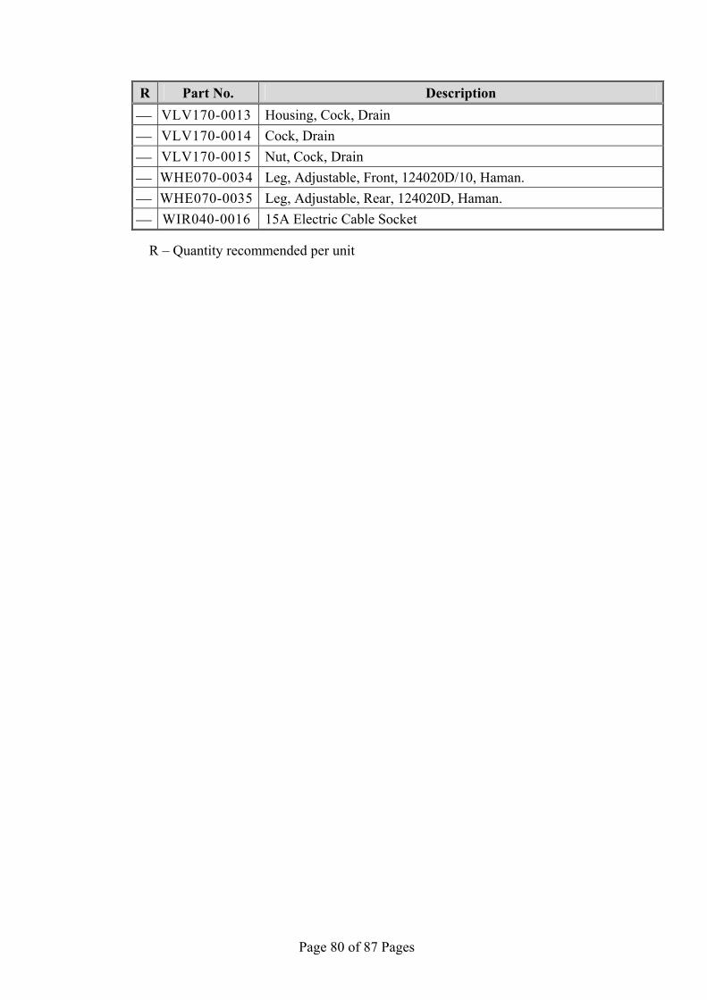
Page 80 of 87 Pages
R Part No. Description VLV170-0013 Housing, Cock, Drain VLV170-0014 Cock, Drain VLV170-0015 Nut, Cock, Drain WHE070-0034 Leg, Adjustable, Front, 124020D/10, Haman. WHE070-0035 Leg, Adjustable, Rear, 124020D, Haman. WIR040-0016 15A Electric Cable Socket
R – Quantity recommended per unit

Page 81 of 87 Pages
12 PRESSURE VS TEMPERATURE FOR SATURATED STEAM °C kPa Bar °F psig psia °C kPa Bar °F InHg psia
104.3 117.9 1.18 219.7 2.4 17.1 45.8 10 0.10 114.5 2.95 1.5 104.4 118.6 1.18 219.9 2.5 17.2 54.1 15 0.15 129.3 4.44 2.2 104.5 118.6 1.19 220.1 2.5 17.2 60.1 20 0.20 140.2 5.90 2.9 104.6 119.3 1.19 220.3 2.6 17.3 65.0 25 0.25 149.1 7.39 3.6 104.7 120.0 1.20 220.5 2.7 17.4 68.9 30 0.30 156.4 8.86 4.4 104.8 120.0 1.20 220.6 2.7 17.4 72.7 35 0.35 162.9 10.34 5.1 104.9 120.4 1.20 220.8 2.8 17.5 75.9 40 0.40 168.6 11.81 5.8 105.0 120.7 1.21 221.0 2.8 17.5 78.8 45 0.45 173.8 13.30 6.5 105.1 121.3 1.21 221.2 2.9 17.6 81.3 50 0.50 178.4 14.76 7.3 105.2 122.0 1.22 221.4 3.0 17.7 105.3 122.0 1.22 221.5 3.0 17.7 °C kPa Bar °F psig psia 105.4 122.7 1.23 221.7 3.1 17.8 100.0101.3 1.01 212.0 0.0 14.7 105.5 122.7 1.23 221.9 3.1 17.8 100.1101.7 1.02 212.2 0.1 14.8 105.6 123.4 1.23 222.1 3.2 17.9 100.2102.1 1.02 212.4 0.1 14.8 105.7 124.1 1.24 222.3 3.3 18.0 100.3102.4 1.02 212.5 0.2 14.9 105.8 124.1 1.24 222.4 3.3 18.0 100.4102.8 1.03 212.7 0.2 14.9 105.9 124.7 1.24 222.6 3.4 18.1 100.5103.2 1.03 212.9 0.3 15.0 106.0 125.1 1.25 222.8 3.5 18.2 100.6103.6 1.04 213.1 0.3 15.0 106.1 125.5 1.26 223.0 3.5 18.2 100.7104.0 1.04 213.3 0.4 15.1 106.2 126.0 1.26 223.2 3.6 18.3 100.8104.3 1.04 213.4 0.4 15.1 106.3 126.2 1.26 223.3 3.6 18.3 100.9104.7 1.05 213.6 0.5 15.2 106.4 126.8 1.27 223.5 3.7 18.4 101.0105.1 1.05 213.8 0.5 15.2 106.5 127.2 1.27 223.7 3.8 18.5 101.1105.4 1.05 214.0 0.6 15.3 106.6 127.7 1.28 223.9 3.8 18.5 101.2105.8 1.06 214.2 0.7 15.4 106.7 128.1 1.28 224.1 3.9 18.6 101.3106.2 1.06 214.3 0.7 15.4 106.8 128.5 1.29 224.2 3.9 18.6 101.4106.6 1.07 214.5 0.8 15.5 106.9 129.0 1.29 224.4 4.0 18.7 101.5106.9 1.07 214.7 0.8 15.5 107.0 129.6 1.29 224.6 4.1 18.8 101.6107.3 1.07 214.9 0.9 15.6 107.1 129.9 1.30 224.8 4.2 18.9 101.7107.7 1.08 215.1 0.9 15.6 107.2 130.4 1.30 225.0 4.2 18.9 101.8108.1 1.08 215.2 1.0 15.7 107.3 130.8 1.31 225.1 4.3 19.0 101.9108.4 1.08 215.4 1.0 15.7 107.4 131.3 1.31 225.3 4.3 19.0 102.0108.8 1.09 215.6 1.1 15.8 107.5 131.7 1.32 225.5 4.4 19.1 102.1109.2 1.09 215.8 1.1 15.8 107.6 132.2 1.32 225.7 4.5 19.2 102.2109.6 1.10 216.0 1.2 15.9 107.7 132.6 1.33 225.9 4.6 19.3 102.4110.0 1.10 216.3 1.3 16.0 107.8 133.1 1.33 226.0 4.6 19.3 102.5110.7 1.11 216.5 1.4 16.1 107.9 133.5 1.34 226.2 4.7 19.4 102.6111.1 1.11 216.7 1.4 16.1 108.0 134.0 1.34 226.4 4.7 19.4 102.7111.5 1.12 216.9 1.5 16.2 108.1 134.4 1.34 226.6 4.8 19.5 102.8111.9 1.12 217.0 1.5 16.2 108.2 134.9 1.35 226.8 4.9 19.6 102.9112.3 1.12 217.2 1.6 16.3 108.3 135.3 1.35 226.9 4.9 19.6 103.0112.7 1.13 217.4 1.7 16.4 108.4 135.8 1.36 227.1 5.0 19.7 103.1113.1 1.13 217.6 1.7 16.4 108.5 136.2 1.36 227.3 5.1 19.8 103.2113.5 1.14 217.8 1.8 16.5 108.6 136.7 1.37 227.5 5.1 19.8 103.3114.0 1.14 217.9 1.8 16.5 108.7 137.1 1.37 227.7 5.2 19.9 103.4114.3 1.14 218.1 1.9 16.6 108.8 137.6 1.38 227.8 5.2 19.9 103.5114.7 1.15 218.3 1.9 16.6 108.9 138.1 1.38 228.0 5.3 20.0 103.6115.1 1.15 218.5 2.0 16.7 109.0 138.5 1.39 228.2 5.4 20.1 103.7115.6 1.16 218.7 2.1 16.8 109.1 139.0 1.39 228.4 5.5 20.2 103.8116.0 1.16 218.8 2.1 16.8 109.2 139.5 1.39 228.6 5.6 20.3 103.9116.3 1.16 219.0 2.2 16.9 109.3 140.0 1.40 228.7 5.6 20.3 104.0116.7 1.17 219.2 2.2 16.9 109.4 140.5 1.40 228.9 5.7 20.4 104.1117.1 1.17 219.4 2.3 17.0 109.5 140.9 1.41 229.1 5.7 20.4 104.2117.5 1.18 219.6 2.4 17.1

Page 82 of 87 Pages
°C kPa Bar °F psig psia °C kPa Bar °F psig psia 115.1 169.7 1.70 239.2 9.9 24.6 109.6141.4 1.41 229.3 5.8 20.5 115.2 170.2 1.70 239.4 10.0 24.7 109.7142.0 1.42 229.5 5.9 20.6 115.3 170.8 1.71 239.5 10.0 24.7 109.8142.4 1.42 229.6 5.9 20.6 115.4 171.3 1.71 239.7 10.1 24.8 109.9142.9 1.43 229.8 6.0 20.7 115.5 171.8 1.72 239.9 10.2 24.9 110.0143.3 1.43 230.0 6.1 20.8 115.6 172.4 1.72 240.1 10.3 25.0 110.1143.9 1.44 230.2 6.2 20.9 115.7 173.1 1.73 240.3 10.4 25.1 110.2144.3 1.44 230.4 6.3 21.0 115.8 173.6 1.74 240.4 10.5 25.2 110.3144.8 1.45 230.5 6.3 21.0 115.9 174.1 1.74 240.6 10.6 25.3 110.4145.3 1.45 230.7 6.4 21.1 116.0 174.7 1.75 240.8 10.6 25.3 110.5145.8 1.46 230.9 6.4 21.1 116.1 175.3 1.75 241.0 10.7 25.4 110.6146.2 1.46 231.1 6.5 21.2 116.2 175.9 1.76 241.2 10.8 25.5 110.7146.7 1.47 231.3 6.6 21.3 116.3 176.4 1.76 241.3 10.9 25.6 110.8147.2 1.47 231.4 6.6 21.3 116.4 177.0 1.77 241.5 11.0 25.7 110.9147.7 1.48 231.6 6.7 21.4 116.5 177.6 1.78 241.7 11.1 25.8 111.0148.2 1.48 231.8 6.8 21.5 116.6 178.2 1.78 241.9 11.2 25.9 111.1148.6 1.49 232.0 6.9 21.6 116.7 178.7 1.79 242.1 11.2 25.9 111.2149.6 1.49 232.2 7.0 21.7 116.8 179.3 1.79 242.2 11.3 26.0 111.3149.6 1.50 232.3 7.0 21.7 116.9 180.0 1.80 242.4 11.4 26.1 111.4150.3 1.50 232.5 7.1 21.8 117.0 180.5 1.80 242.6 11.5 26.2 111.5151.0 1.51 232.7 7.2 21.9 117.1 181.1 1.81 242.8 11.6 26.3 111.6151.0 1.51 232.9 7.2 21.9 117.2 181.6 1.82 243.0 11.7 26.4 111.7151.7 1.52 233.1 7.3 22.0 117.3 182.2 1.82 243.1 11.7 26.4 111.8152.2 1.52 233.2 7.4 22.1 117.4 182.8 1.83 243.3 11.8 26.5 111.9152.7 1.53 233.4 7.4 22.1 117.5 183.4 1.83 243.5 11.9 26.6 112.0153.2 1.53 233.6 7.5 22.2 117.6 184.0 1.84 243.7 12.0 26.7 112.1153.8 1.54 233.8 7.6 22.3 117.7 184.5 1.85 243.9 12.1 26.8 112.2154.3 1.54 234.0 7.7 22.4 117.8 185.1 1.85 244.0 12.1 26.8 112.3154.8 1.55 234.1 7.7 22.4 117.9 185.7 1.86 244.2 12.2 26.9 112.4155.3 1.55 234.3 7.8 22.5 118.0 186.3 1.86 244.4 12.3 27.0 112.5155.8 1.56 234.5 7.9 22.6 118.1 186.9 1.87 244.6 12.4 27.1 112.6156.3 1.56 234.7 8.0 22.7 118.2 187.5 1.88 244.8 12.5 27.2 112.7156.8 1.57 234.9 8.1 22.8 118.3 188.2 1.88 244.9 12.6 27.3 112.8157.3 1.57 235.0 8.1 22.8 118.4 188.8 1.89 245.1 12.7 27.4 112.9157.9 1.58 235.2 8.2 22.9 118.5 189.4 1.89 245.3 12.8 27.5 113.0158.4 1.58 235.4 8.3 23.0 118.6 190.0 1.90 245.5 12.9 27.6 113.1158.9 1.59 235.6 8.4 23.1 118.7 190.6 1.91 245.7 13.0 27.7 113.2159.4 1.59 235.8 8.4 23.1 118.8 191.2 1.91 245.8 13.0 27.7 113.3159.9 1.60 235.9 8.5 23.2 118.9 191.8 1.92 246.0 13.1 27.8 113.4160.4 1.60 236.1 8.6 23.3 119.0 192.4 1.92 246.2 13.2 27.9 113.5160.0 1.61 236.3 8.7 23.4 119.1 193.0 1.93 246.4 13.3 28.0 113.6161.5 1.62 236.5 8.7 23.4 119.2 193.7 1.94 246.6 13.4 28.1 113.7162.1 1.62 236.7 8.8 23.5 119.3 194.3 1.94 246.7 13.5 28.2 113.8162.6 1.63 236.8 8.9 23.6 119.4 194.9 1.95 246.9 13.6 28.3 113.9163.1 1.63 237.0 9.0 23.7 119.5 195.5 1.95 247.1 13.7 28.4 114.0163.7 1.64 237.2 9.0 23.7 119.6 196.1 1.96 247.3 13.8 28.5 114.1164.2 1.64 237.4 9.1 23.8 119.7 196.7 1.97 247.5 13.9 28.6 114.2164.8 1.65 237.6 9.2 23.9 119.8 197.3 1.97 247.6 13.9 28.6 114.3165.3 1.65 237.7 9.3 24.0 119.9 197.9 1.98 247.8 14.0 28.7 114.4165.9 1.66 237.9 9.4 24.1 120.0 198.5 1.99 248.0 14.1 28.8 114.5166.4 1.66 238.1 9.4 24.1 120.1 199.2 1.99 248.2 14.2 28.9 114.6167.0 1.67 238.3 9.5 24.2 120.2 199.8 2.00 248.4 14.3 29.0 114.7167.5 1.67 238.5 9.6 24.3 120.3 200.5 2.00 248.5 14.4 29.1 114.8168.0 1.68 238.6 9.7 24.4 120.4 201.1 2.01 248.7 14.5 29.2 114.9168.6 1.69 238.8 9.7 24.4 120.5 201.8 2.02 248.9 14.6 29.3 115.0169.1 1.69 239.0 9.8 24.5

Page 83 of 87 Pages
°C kPa Bar °F psig psia °C kPa Bar °F psig psia 125.9 238.7 2.39 258.6 19.9 34.6 120.6202.4 2.02 249.1 14.7 29.4 126.0 239.4 2.39 258.8 20.0 34.7 120.7203.1 2.03 249.3 14.8 29.5 126.1 240.2 2.40 259.0 20.1 34.8 120.8203.7 2.04 249.4 14.8 29.5 126.2 240.9 2.41 259.2 20.2 34.9 120.9204.4 2.04 249.6 14.9 29.6 126.3 241.6 2.42 259.3 20.3 35.0 121.0205.0 2.05 249.8 15.0 29.7 126.4 242.3 2.42 259.5 20.4 35.1 121.1205.7 2.06 250.0 15.3 29.8 126.5 243.1 2.43 259.7 20.6 35.3 121.2206.3 2.06 250.2 15.4 29.9 126.6 243.8 2.44 259.9 20.7 35.4 121.3207.0 2.07 250.3 15.5 30.0 126.7 244.5 2.45 260.1 20.8 35.5 121.4207.6 2.08 250.5 15.6 30.1 126.8 245.3 2.45 260.2 20.9 35.6 121.5208.3 2.08 250.7 15.6 30.3 126.9 246.0 2.46 260.4 21.0 35.7 121.6208.9 2.09 250.9 15.8 30.5 127.0 246.8 2.47 260.6 21.1 35.8 121.7209.6 2.10 251.1 15.8 30.5 127.1 247.6 2.48 260.8 21.2 35.9 121.8210.2 2.10 251.2 15.9 30.6 127.2 248.3 2.48 261.0 21.3 36.0 121.9210.8 2.11 251.4 16.0 30.7 127.3 249.1 2.49 261.1 21.4 36.1 122.0211.5 2.11 251.6 16.1 30.8 127.4 249.9 2.50 261.3 21.5 36.2 122.1212.1 2.12 251.8 16.3 31.0 127.5 250.6 2.51 261.5 21.8 36.5 122.2212.8 2.13 252.0 16.3 31.0 127.6 251.4 2.51 261.7 21.8 36.5 122.3213.5 2.13 252.1 16.4 31.1 127.7 252.2 2.52 261.9 21.9 36.6 122.4214.2 2.14 252.3 16.5 31.2 127.8 252.9 2.53 262.0 22.0 36.7 122.5214.8 2.15 252.5 16.6 31.3 127.9 253.7 2.54 262.2 22.1 36.8 122.6215.2 2.16 252.7 16.7 31.4 128.0 254.5 2.54 262.4 22.2 36.9 122.7216.2 2.16 252.9 16.8 31.5 128.1 255.2 2.55 262.6 22.3 37.0 122.8216.9 2.17 253.0 16.9 31.6 128.2 256.0 2.56 262.8 22.4 37.1 122.9217.6 2.18 253.2 17.0 31.7 128.3 256.8 2.57 262.9 22.5 37.2 123.0218.3 2.18 253.4 17.1 31.8 128.4 257.5 2.58 263.1 22.7 37.4 123.1218.9 2.19 253.6 17.1 31.8 128.5 258.3 2.58 263.3 22.8 37.5 123.2219.6 2.20 253.8 17.2 31.9 128.6 259.1 2.59 263.5 22.9 37.6 123.3220.3 2.20 253.9 17.3 32.0 128.7 259.8 2.60 263.7 23.0 37.7 123.4221.0 2.21 254.1 17.4 32.1 128.8 260.6 2.61 263.8 23.1 37.8 123.5221.7 2.22 254.3 17.5 32.2 128.9 261.4 2.61 264.0 23.2 37.9 123.6222.4 2.22 254.5 17.6 32.3 129.0 262.2 2.62 264.2 23.3 38.0 123.7223.1 2.23 254.7 17.7 32.4 129.1 263.0 2.63 264.4 23.4 38.1 123.8223.7 2.24 254.8 17.8 32.5 129.2 263.8 2.64 264.6 23.6 38.3 123.9224.4 2.24 255.0 17.9 32.6 129.3 264.6 2.65 264.7 23.7 38.4 124.0225.1 2.25 255.2 17.9 32.6 129.4 265.4 2.65 264.9 23.8 38.5 124.1225.8 2.26 255.4 18.0 32.7 129.5 266.2 2.66 265.1 23.9 38.6 124.2226.5 2.26 255.6 18.1 32.8 129.6 267.0 2.67 265.3 24.0 38.7 124.3227.2 2.27 255.7 18.2 32.9 129.7 267.8 2.68 265.5 24.1 38.8 124.4227.9 2.28 255.9 18.3 33.0 129.8 268.6 2.69 265.6 24.3 39.0 124.5228.6 2.29 256.1 18.4 33.1 129.9 269.4 2.69 265.8 24.4 39.1 124.6229.3 2.29 256.3 18.6 33.3 130.0 270.3 2.70 266.0 24.5 39.2 124.7230.0 2.30 256.5 18.7 33.4 130.1 271.1 2.71 266.2 24.6 39.3 124.8230.7 2.31 256.6 18.8 33.5 130.2 271.9 2.72 266.4 24.7 39.4 124.9231.5 2.31 256.8 18.9 33.6 130.3 272.7 2.73 266.5 24.8 39.5 125.0232.2 2.32 257.0 19.0 33.7 130.4 273.5 2.73 266.7 25.0 39.7 125.1232.9 2.33 257.2 19.1 33.8 130.5 274.3 2.74 266.9 25.1 39.8 125.2233.6 2.34 257.4 19.2 33.9 130.6 275.1 2.75 267.1 25.2 39.9 125.3234.4 2.34 257.5 19.3 34.0 130.7 275.9 2.76 267.3 25.3 40.0 125.4235.1 2.35 257.7 19.4 34.1 130.8 276.7 2.77 267.4 25.4 40.1 125.5235.8 2.36 257.9 19.5 34.2 130.9 277.5 2.78 267.6 25.6 40.3 125.6236.5 2.37 258.1 19.6 34.3 131.0 278.3 2.78 267.8 25.7 40.4 125.7237.3 2.37 258.3 19.7 34.4 131.1 279.1 2.79 268.0 25.8 40.5 125.8238.0 2.38 258.4 19.8 34.5
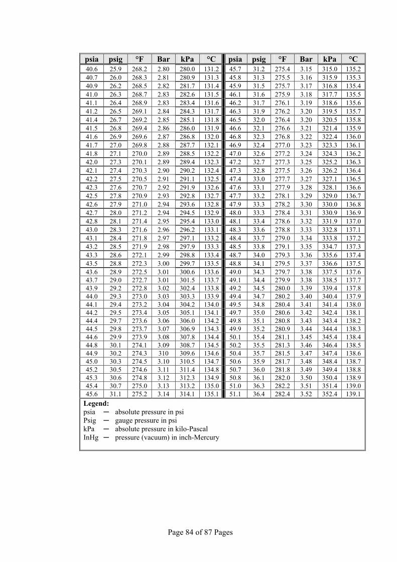
Page 84 of 87 Pages
°C kPa Bar °F psig psia °C kPa Bar °F psig psia 135.2 315.0 3.15 275.4 31.2 45.7 131.2280.0 2.80 268.2 25.9 40.6 135.3 315.9 3.16 275.5 31.3 45.8 131.3280.9 2.81 268.3 26.0 40.7 135.4 316.8 3.17 275.7 31.5 45.9 131.4281.7 2.82 268.5 26.2 40.9 135.5 317.7 3.18 275.9 31.6 46.1 131.5282.6 2.83 268.7 26.3 41.0 135.6 318.6 3.19 276.1 31.7 46.2 131.6283.4 2.83 268.9 26.4 41.1 135.7 319.5 3.20 276.2 31.9 46.3 131.7284.3 2.84 269.1 26.5 41.2 135.8 320.5 3.20 276.4 32.0 46.5 131.8285.1 2.85 269.2 26.7 41.4 135.9 321.4 3.21 276.6 32.1 46.6 131.9286.0 2.86 269.4 26.8 41.5 136.0 322.4 3.22 276.8 32.3 46.8 132.0286.8 2.87 269.6 26.9 41.6 136.1 323.3 3.23 277.0 32.4 46.9 132.1287.7 2.88 269.8 27.0 41.7 136.2 324.3 3.24 277.2 32.6 47.0 132.2288.5 2.89 270.0 27.1 41.8 136.3 325.2 3.25 277.3 32.7 47.2 132.3289.4 2.89 270.1 27.3 42.0 136.4 326.2 3.26 277.5 32.8 47.3 132.4290.2 2.90 270.3 27.4 42.1 136.5 327.1 3.27 277.7 33.0 47.4 132.5291.1 2.91 270.5 27.5 42.2 136.6 328.1 3.28 277.9 33.1 47.6 132.6291.9 2.92 270.7 27.6 42.3 136.7 329.0 3.29 278.1 33.2 47.7 132.7292.8 2.93 270.9 27.8 42.5 136.8 330.0 3.30 278.2 33.3 47.9 132.8293.6 2.94 271.0 27.9 42.6 136.9 330.9 3.31 278.4 33.3 48.0 132.9294.5 2.94 271.2 28.0 42.7 137.0 331.9 3.32 278.6 33.4 48.1 133.0295.4 2.95 271.4 28.1 42.8 137.1 332.8 3.33 278.8 33.6 48.3 133.1296.2 2.96 271.6 28.3 43.0 137.2 333.8 3.34 279.0 33.7 48.4 133.2297.1 2.97 271.8 28.4 43.1 137.3 334.7 3.35 279.1 33.8 48.5 133.3297.9 2.98 271.9 28.5 43.2 137.4 335.6 3.36 279.3 34.0 48.7 133.4298.8 2.99 272.1 28.6 43.3 137.5 336.6 3.37 279.5 34.1 48.8 133.5299.7 3.00 272.3 28.8 43.5 137.6 337.5 3.38 279.7 34.3 49.0 133.6300.6 3.01 272.5 28.9 43.6 137.7 338.5 3.38 279.9 34.4 49.1 133.7301.5 3.01 272.7 29.0 43.7 137.8 339.4 3.39 280.0 34.5 49.2 133.8302.4 3.02 272.8 29.2 43.9 137.9 340.4 3.40 280.2 34.7 49.4 133.9303.3 3.03 273.0 29.3 44.0 138.0 341.4 3.41 280.4 34.8 49.5 134.0304.2 3.04 273.2 29.4 44.1 138.1 342.4 3.42 280.6 35.0 49.7 134.1305.1 3.05 273.4 29.5 44.2 138.2 343.4 3.43 280.8 35.1 49.8 134.2306.0 3.06 273.6 29.7 44.4 138.3 344.4 3.44 280.9 35.2 49.9 134.3306.9 3.07 273.7 29.8 44.5 138.4 345.4 3.45 281.1 35.4 50.1 134.4307.8 3.08 273.9 29.9 44.6 138.5 346.4 3.46 281.3 35.5 50.2 134.5308.7 3.09 274.1 30.1 44.8 138.6 347.4 3.47 281.5 35.7 50.4 134.6309.6 310 274.3 30.2 44.9 138.7 348.4 3.48 281.7 35.9 50.6 134.7310.5 3.10 274.5 30.3 45.0 138.8 349.4 3.49 281.8 36.0 50.7 134.8311.4 3.11 274.6 30.5 45.2 138.9 350.4 3.50 282.0 36.1 50.8 134.9312.3 3.12 274.8 30.6 45.3 139.0 351.4 3.51 282.2 36.3 51.0 135.0313.2 3.13 275.0 30.7 45.4 139.1 352.4 3.52 282.4 36.4 51.1 135.1314.1 3.14 275.2 31.1 45.6
Legend: psia absolute pressure in psi Psig gauge pressure in psi kPa absolute pressure in kilo-Pascal InHg pressure (vacuum) in inch-Mercury
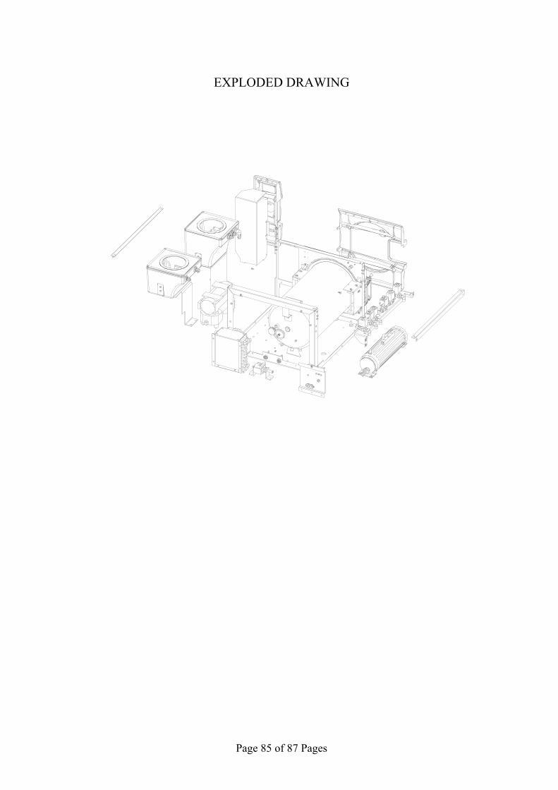
Page 85 of 87 Pages
EXPLODED DRAWING
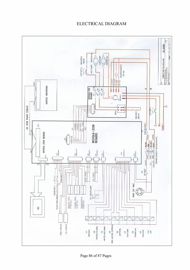
Page 86 of 87 Pages
ELECTRICAL DIAGRAM

Page 87 of 87 Pages
PIPING DIAGRAM