lvs 9570 operating instructions - assets.omron.eu®_9570_operating... · lvs-9570 operating...
TRANSCRIPT
P/N 84-9310010-02 Rev A
LVS® 9570 Operating Instructions

LVS-9570 Operating Instructions
LVS-9570 Operating Instructions Page 2 of 28
Copyright ©2019 Omron Microscan Systems, Inc. Tel: +1.425.226.5700 / 800.762.1149 Fax: +1.425.226.8250
All rights reserved. The information contained herein is proprietary and is provided solely for the purpose of allowing customers to operate and/or service Omron Microscan-manufactured equipment and is not to be released, reproduced, or used for any other purpose without written permission of Omron Microscan.
Throughout this manual, trademarked names might be used. We state herein that we are using the names to the benefit of the trademark owner, with no intention of infringement.
GS1 Solution Partner
Disclaimer The information and specifications described in this manual are subject to change without notice.
Latest Manual Version For the latest version of this manual, see the Download Center on our web site at: www.microscan.com.
Technical Support For technical support, e-mail: [email protected] [email protected] [email protected] [email protected]
Warranty For current warranty information, see: www.microscan.com/warranty.
Omron Microscan Systems, Inc.
United States Corporate Headquarters +1.425.226.5700 / 800.762.1149
United States Northeast Technology Center +1.603.598.8400 / 800.468.9503
European Headquarters +31.172.423360
Asia Pacific Headquarters +65.6846.1214
LVS-9570 Operating Instructions
LVS-9570 Operating Instructions Page 3 of 28
Table of Contents
IMPORTANT INFORMATION .......................................................................................................... 4
SAFETY INSTRUCTIONS ............................................................................................................... 4
ABOUT THE LVS-9570 ................................................................................................................... 5
LVS-95XX SOFTWARE STEPS ...................................................................................................... 6
Log In to LVS-95XX Software ..................................................................................................... 6
Turn On the LVS-9570 Camera .................................................................................................. 7
Calibrate the LVS-9570 ............................................................................................................... 8
HARDWARE OVERVIEW .............................................................................................................. 13 Front of System ......................................................................................................................... 13
Back of System ......................................................................................................................... 13
SCANNING DIRECTION, SPEED, AND POSITION ..................................................................... 14 Quiet Zone ................................................................................................................................. 15
Linear (1D) Barcode Quiet Zones .......................................................................................... 15
Two-Dimensional (2D) Quiet Zones ....................................................................................... 15
Scanning Direction .................................................................................................................... 16
Scanning Speed ........................................................................................................................ 17
Scanning Positions .................................................................................................................... 18
Ladder Orientation ................................................................................................................. 18
Picket Fence Orientation ........................................................................................................ 18
Correct and Incorrect Images ................................................................................................ 19
SCANNING LABELS APPLIED TO PRODUCTS ......................................................................... 21
Corrugated Cardboard Boxes ................................................................................................... 21
Shipping Containers .................................................................................................................. 22
Web Scanning ........................................................................................................................... 22
Desktop Scanning ..................................................................................................................... 22
CLEANING INSTRUCTIONS ......................................................................................................... 23 Clean the Sensor Window ......................................................................................................... 23
Clean the Rubber Roller ............................................................................................................ 24
Window Scratches .................................................................................................................... 24
ADDITIONAL RESOURCES .......................................................................................................... 25
ENGINEERING SPECIFICATIONS ............................................................................................... 26 Supported Symbologies and Standards ................................................................................... 27
Supported Symbologies ......................................................................................................... 27
Supported Standards ............................................................................................................. 27

LVS-9570 Operating Instructions
LVS-9570 Operating Instructions Page 4 of 28
Important Information The LVS-9570 arrives to your site packaged in a specially designed shipping carton. DO NOT discard
this shipping carton in case you must ship or store the system for any reason. Failure to use this carton when returning your product to Omron Microscan will void warranty.
This guide is intended to help you understand the features and functionality of the LVS-9570. Be sure to reference the following additional resources:
o LVS-9570 video demonstration located on the flash drive supplied with your system.
o Refer to the “LVS-95XX Series Software Installation Guide” for steps on installing the LVS-95XX software; a hard copy version of this manual is packaged with your system and an electronic version is located on the installation media supplied with your system.
o Refer to the “LVS-95XX Series Barcode Quality Station Operations Manual” for comprehensive steps on operating the LVS-95XX software. This manual is located on the installation media supplied with your system.
If you have any questions or concerns about the performance of the LVS-9570, please call your local Omron Microscan distributor or Omron Microscan technical support:
Omron Microscan Technical Support:
+1-425-203-4841 | +1-800-762-1149 | [email protected]
Safety Instructions The LVS-9570 has been carefully designed to provide years of safe, reliable performance. However, as with all electrical equipment, there are some basic precautions you should follow to avoid personal injury or damage to the system:
Before using the system, carefully read all the installation and operating instructions.
Observe all warning instruction labels on the system.
Never insert anything into the openings of the system.
Do not use the system near water or spill liquid into it.
All components used to create your system are UL and CE approved. All circuits were designed to incorporate maximum safety. However, any equipment using electrical voltages may cause personal injury if improperly handled.
Do not attempt to work on the system with the USB cable connected.
To avoid damaging the system, unplug the USB cable before cleaning.
If the system ever needs repair, consult Omron Microscan or your Omron Microscan distributor.

LVS-9570 Operating Instructions
LVS-9570 Operating Instructions Page 5 of 28
About the LVS-9570 The LVS-9570 is a handheld barcode verifier designed for offline verification of barcodes to ISO/IEC standards. The LVS-9570 is unique in the world of ISO verification due to its ease of use and ability to verify linear (1D) and two-dimensional (2D) codes using a lightweight, handheld verifier; autodiscriminate the symbology, narrow bar width and aperture to be used to evaluate the code; and highlight trouble spots in the code.
The LVS-9570 verifies barcode labels located on any flat surface, including barcode labels on corrugated cardboard boxes, shipping containers, or on a web.
The LVS-9570 is a line scan, camera-based system. An image of the barcode label is generated by placing the LVS-9570 flat onto the surface of a barcode label and scanning through the barcode label in either a ladder or picket fence orientation (see the “Scanning Direction, Speed, and Position” section for more information on ladder and picket fence orientations).

LVS-9570 Operating Instructions
LVS-9570 Operating Instructions Page 6 of 28
LVS-95XX Software Steps Refer to the sections below for steps on:
Logging on to the LVS-95XX software
Turning on the camera
Calibrating the LVS-9570
Note: Refer to the “LVS-95XX Series Software Installation Guide” for step-by-step instructions on installing the LVS-95XX software; a hard copy version of this guide is packaged with your system and an electronic version is located on the installation media supplied with your system.
Log In to LVS-95XX Software To log on to the LVS-95XX software, click the “Setup” tab. The “Login” box appears.
Enter “admin” (not case sensitive) in the “Operator ID” field and “admin” (not case sensitive) in the “Password” field, and then click “OK.” You are now logged in to the LVS-9570.
You next need to turn on the LVS-9570 camera. See the next section for detailed steps on turning on the LVS-9570 camera.
LVS-9570 Operating Instructions
LVS-9570 Operating Instructions Page 7 of 28
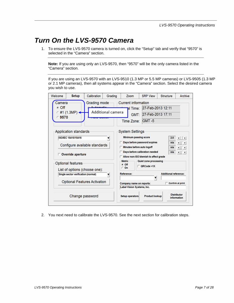
Turn On the LVS-9570 Camera 1. To ensure the LVS-9570 camera is turned on, click the “Setup” tab and verify that “9570” is
selected in the “Camera” section.
Note: If you are using only an LVS-9570, then “9570” will be the only camera listed in the “Camera” section.
If you are using an LVS-9570 with an LVS-9510 (1.3 MP or 5.5 MP cameras) or LVS-9505 (1.3 MP or 2.1 MP cameras), then all systems appear in the “Camera” section. Select the desired camera you wish to use.
2. You next need to calibrate the LVS-9570. See the next section for calibration steps.

LVS-9570 Operating Instructions
LVS-9570 Operating Instructions Page 8 of 28
Calibrate the LVS-9570
IMPORTANT: Calibrate the LVS-9570 at least weekly, if not daily. The entire calibration process takes less than 30 seconds to complete and ensures the LVS-9570 is certified according to industry standards. The Calibrated Conformance Standard Test Card should be replaced every two years. It is recommended to clean the sensor glass prior to calibration. See the “Cleaning the Sensor
Window” section for more information.
1. To calibrate the LVS-9570, click the “Calibration” tab.
The field of view and the parameters in the “Goal” and “Actual” columns are empty until the calibration card is scanned (as directed in the next step).
LVS-9570 Operating Instructions
LVS-9570 Operating Instructions Page 9 of 28
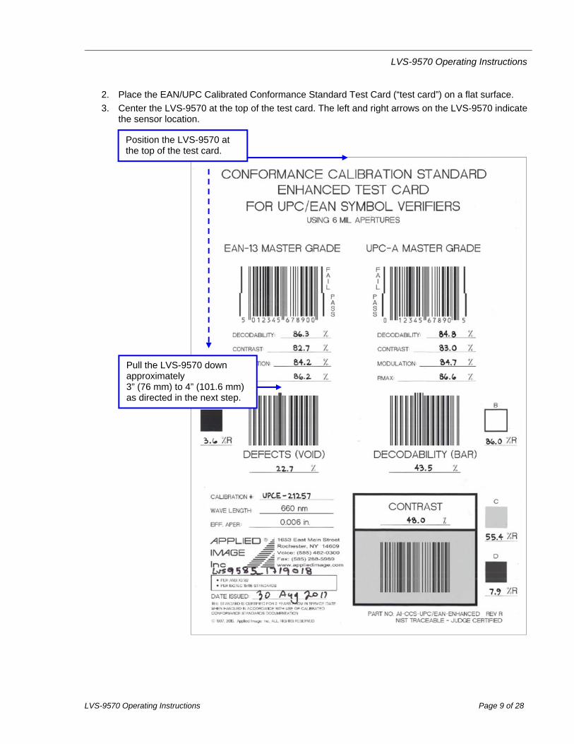
2. Place the EAN/UPC Calibrated Conformance Standard Test Card (“test card”) on a flat surface.
3. Center the LVS-9570 at the top of the test card. The left and right arrows on the LVS-9570 indicate the sensor location.
Pull the LVS-9570 down approximately 3” (76 mm) to 4” (101.6 mm) as directed in the next step.
Position the LVS-9570 at the top of the test card.

LVS-9570 Operating Instructions
LVS-9570 Operating Instructions Page 10 of 28
4. Slowly pull down the LVS-9570 approximately 3” (76 mm) to 4” (101.6 mm). The EAN-13 and UPC-A Master Grade barcodes appear in the field of view on the Calibration tab.
The blue line must pass through the “PASS” portion of the barcode.
EAN-13 and UPC-A Master Grade barcode appearing in the field of view.

LVS-9570 Operating Instructions
LVS-9570 Operating Instructions Page 11 of 28
5. Using the mouse, click one time in the “PASS” portion of the EAN-13 or UPC-A Master Grade barcode. The blue line will move to the “PASS” portion of the barcode.
6. Click the “Calibrate” button.
Successful calibration is indicated by a green “Calibration OK” message.
Failed calibration is indicated by a red “Calibration Needed” message.
If calibration fails:
Re-scan the EAN-13 and UPC-A Master Grade barcodes and follow the above steps to calibrate. It may take 2 or 3 attempts before calibration is complete.
If calibration continues to fail, contact Omron Microscan or your Omron Microscan representative for further instructions.
IMPORTANT: The calibration score will hardly ever match exactly. This is normal and acceptable as long as the scores are within +/- 5 percent.
7. When calibration is complete, click the “Grading” tab to grade the desired barcodes. To grade a barcode, scan a barcode image, draw a box around the PASS portion of the barcode, ensuring enough space for the quiet zone (see the “Quiet Zone” section for more information). The verification results display immediately. Refer to the “Grading tab” section in the “LVS-95XX Series Barcode Quality Station Operations Manual” for detailed steps on grading barcodes; this manual is located on the installation media supplied with your system.
LVS-9570 Operating Instructions
LVS-9570 Operating Instructions Page 12 of 28
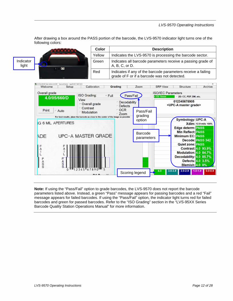
After drawing a box around the PASS portion of the barcode, the LVS-9570 indicator light turns one of the following colors:
Color Description
Yellow Indicates the LVS-9570 is processing the barcode sector.
Green Indicates all barcode parameters receive a passing grade of A, B, C, or D.
Red Indicates if any of the barcode parameters receive a failing grade of F or if a barcode was not detected.
Note: If using the “Pass/Fail” option to grade barcodes, the LVS-9570 does not report the barcode parameters listed above. Instead, a green “Pass” message appears for passing barcodes and a red “Fail” message appears for failed barcodes. If using the “Pass/Fail” option, the indicator light turns red for failed barcodes and green for passed barcodes. Refer to the “ISO Grading” section in the “LVS-95XX Series Barcode Quality Station Operations Manual” for more information.
Indicator light
Scoring legend
Barcode parameters
Pass/Fail grading option
LVS-9570 Operating Instructions
LVS-9570 Operating Instructions Page 13 of 28
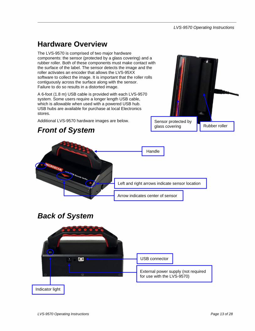
Hardware Overview The LVS-9570 is comprised of two major hardware components: the sensor (protected by a glass covering) and a rubber roller. Both of these components must make contact with the surface of the label. The sensor detects the image and the roller activates an encoder that allows the LVS-95XX software to collect the image. It is important that the roller rolls contiguously across the surface along with the sensor. Failure to do so results in a distorted image.
A 6-foot (1.8 m) USB cable is provided with each LVS-9570 system. Some users require a longer length USB cable, which is allowable when used with a powered USB hub. USB hubs are available for purchase at local Electronics stores.
Additional LVS-9570 hardware images are below.
Front of System
Back of System
Sensor protected by glass covering Rubber roller
Handle
Left and right arrows indicate sensor location
Arrow indicates center of sensor
USB connector
Indicator light
External power supply (not required for use with the LVS-9570)

LVS-9570 Operating Instructions
LVS-9570 Operating Instructions Page 14 of 28
Scanning Direction, Speed, and Position The LVS-9570 has a scanning width of 5.4” (137.16 mm) (including the quiet zone) for barcodes in a picket fence orientation and a scanning length of 12.0” (305 mm) (including the quiet zone) for barcodes in a ladder orientation. See the “Quiet Zone” section for more information on quiet zones.
PICKET FENCE ORIENTATION
The LVS-9570 has a scanning width of 5.4” (137.16 mm) for barcodes in a picket fence
orientation
LADDER ORIENTATION
The LVS-9570 has a scanning length of 12.0” (305 mm) for barcodes in a ladder
orientation
Scanning Direction
5.4” (137.16 mm) Scanning Width
Scanning Direction
12.0” (305 mm) Scanning Length
LVS-9570 Operating Instructions
LVS-9570 Operating Instructions Page 15 of 28
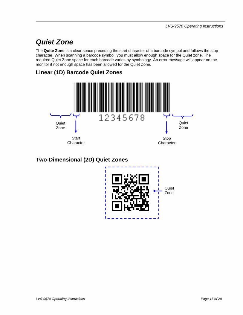
Quiet Zone The Quite Zone is a clear space preceding the start character of a barcode symbol and follows the stop character. When scanning a barcode symbol, you must allow enough space for the Quiet zone. The required Quiet Zone space for each barcode varies by symbology. An error message will appear on the monitor if not enough space has been allowed for the Quiet Zone.
Linear (1D) Barcode Quiet Zones
Two-Dimensional (2D) Quiet Zones
Start Character
Stop Character
Quiet Zone
Quiet Zone
Quiet Zone

LVS-9570 Operating Instructions
LVS-9570 Operating Instructions Page 16 of 28
Scanning Direction The LVS-9570 reads barcode labels in one direction only and must be “pulled” through a barcode label; it does not detect anything when “pushed” through a barcode label.
IMPORTANT: An image is collected only when the roller is rotating while the sensor passes over the barcode image.
CORRECT INCORRECT
“Pull” the LVS-9570 through a barcode label.
DO NOT “push” the LVS-9570 through a barcode label.
Back of system
Back of system
LVS-9570 Operating Instructions
LVS-9570 Operating Instructions Page 17 of 28
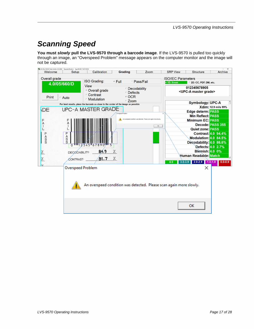
Scanning Speed You must slowly pull the LVS-9570 through a barcode image. If the LVS-9570 is pulled too quickly through an image, an “Overspeed Problem” message appears on the computer monitor and the image will not be captured.

LVS-9570 Operating Instructions
LVS-9570 Operating Instructions Page 18 of 28
Scanning Positions It is important to maintain a perpendicular orientation to the barcode image. Failure to do so may result in a distorted image. If the image displayed on the monitor appears distorted, scan the image again making sure the LVS-9570 is using a perpendicular orientation to the barcode and is pulled slowly. See the “Correct and Incorrect Images” section for examples of correctly and incorrectly scanned barcode images.
Ladder Orientation If scanning a barcode in a ladder orientation, place the LVS-9570 at the top of the barcode with the back of the system facing the operator (see “A” below).
You may also scan from the bottom of the barcode as long as you are leading with the back side of the system (see “B” below).
When scanning, be sure to include space for the Quiet Zone.
Picket Fence Orientation If scanning a barcode in a picket fence orientation, place the LVS-9570 at the top of the barcode and scan the barcode leading with the back of the system, ensuring enough space for the Quiet Zone.
A B
Back of system
Begin scanning with the back side of the system

LVS-9570 Operating Instructions
LVS-9570 Operating Instructions Page 19 of 28
Correct and Incorrect Images
Correctly Scanned Image:
Incorrectly Scanned Image: The image below shows an incorrectly scanned image created by sliding the LVS-9570 in a non-perpendicular way. When scanning an image, the LVS-9570 must maintain a perpendicular orientation to the barcode image.
LVS-9570 Operating Instructions
LVS-9570 Operating Instructions Page 20 of 28
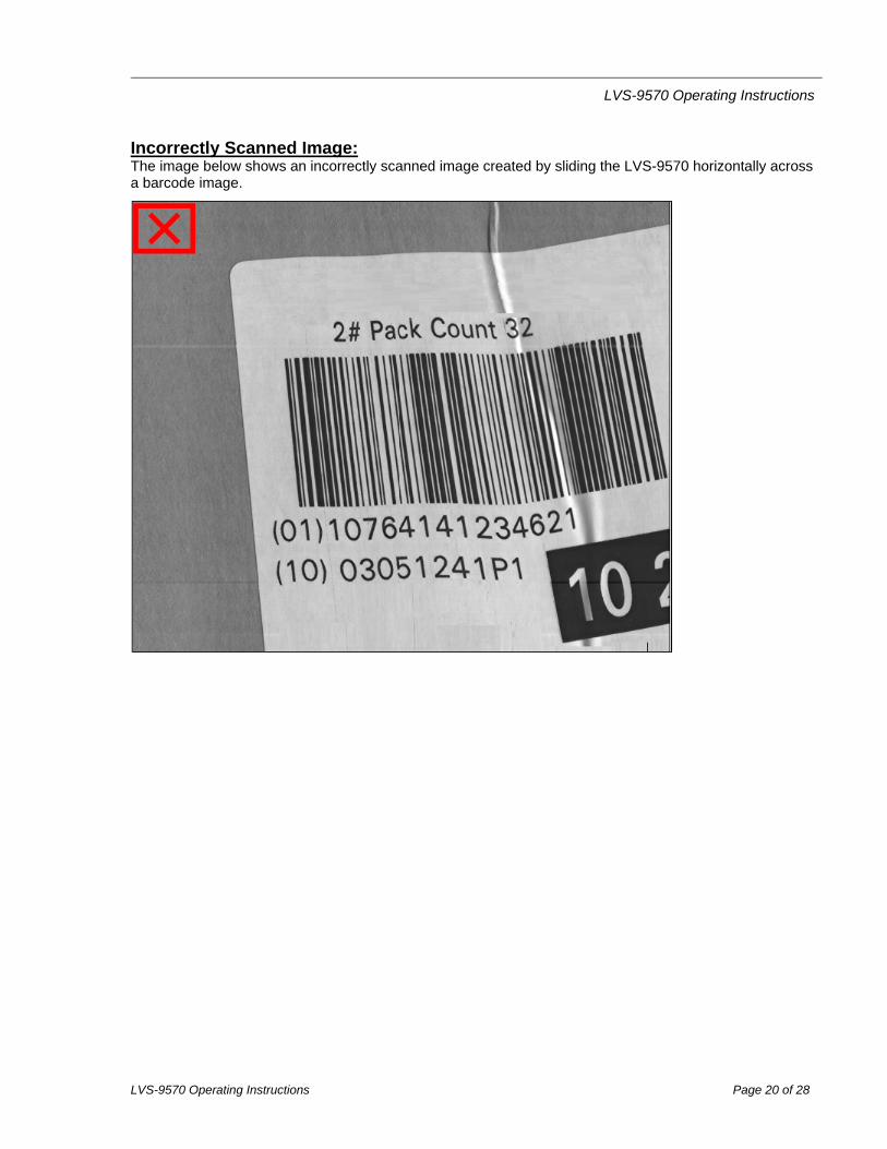
Incorrectly Scanned Image: The image below shows an incorrectly scanned image created by sliding the LVS-9570 horizontally across a barcode image.
LVS-9570 Operating Instructions
LVS-9570 Operating Instructions Page 21 of 28
Scanning Labels Applied to Products
IMPORTANT: The LVS-9570 reads flat surfaces only. Uneven surfaces, such as a bag of potato chips for example, cannot be read due to the uneven surface.
An image is collected only when the roller is rotating while the sensor passes over the image of the barcode and only if the user pulls down on the LVS-9570. The LVS-9570 will not read anything when pushed upwards through a barcode image.
Corrugated Cardboard Boxes It is best to scan corrugated cardboard boxes in a picket fence orientation due to the uneven surface typically found on this type of substrate. However, if the label is too wide to scan in picket fence orientation, then scan the label in ladder orientation. See the “Scanning Direction, Speed and Position” section for more information on picket fence and ladder orientations.
When scanning, be sure to include space for the Quiet Zone.
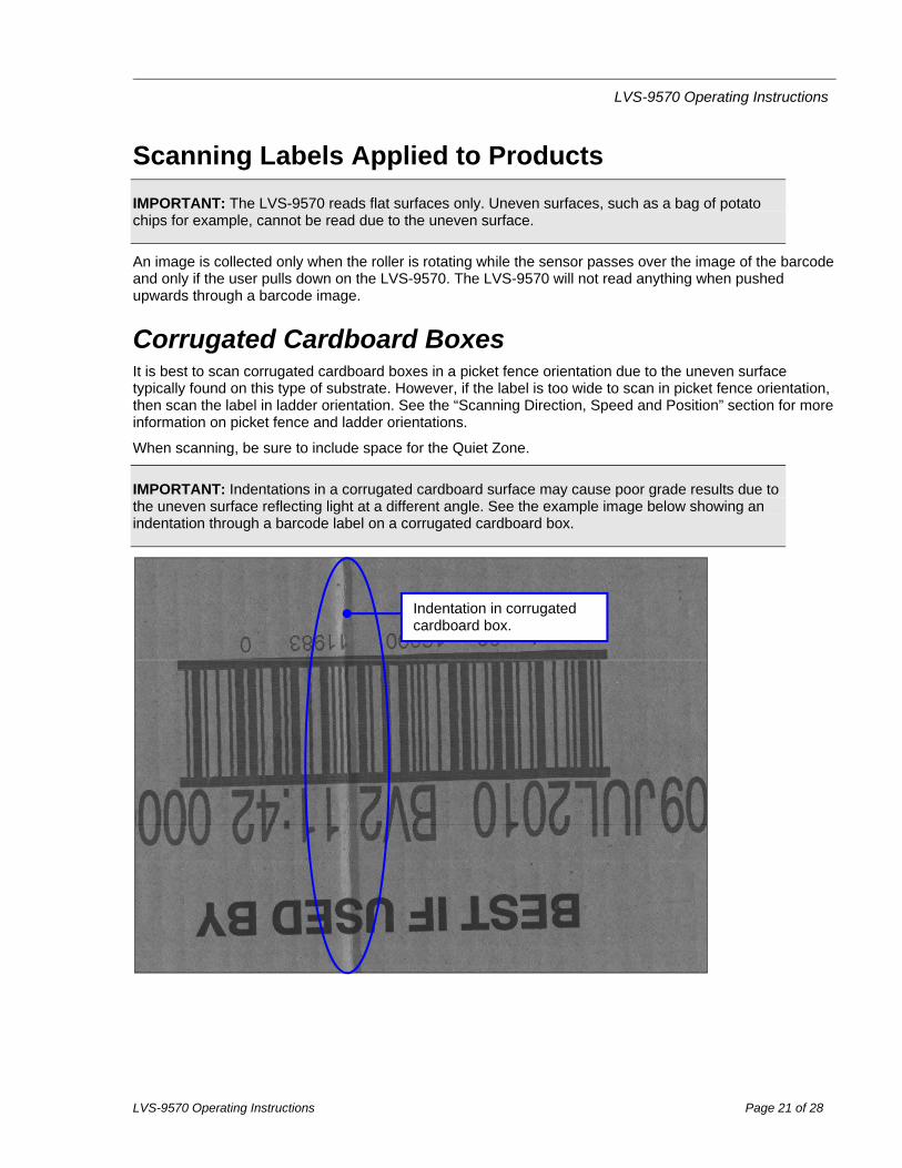
IMPORTANT: Indentations in a corrugated cardboard surface may cause poor grade results due to the uneven surface reflecting light at a different angle. See the example image below showing an indentation through a barcode label on a corrugated cardboard box.
Indentation in corrugated cardboard box.
LVS-9570 Operating Instructions
LVS-9570 Operating Instructions Page 22 of 28
Shipping Containers A shipping container must be flat and the LVS-9570 must be placed onto the shipping container in such a way that the sensor (glass window) and roller is located on the same surface.
You may use the picket fence orientation to pull the LVS-9570 through the entire height of the barcode from top to bottom, or use the ladder orientation to pull the LVS-9570 across the barcode label. See the “Scanning Direction, Speed and Position” section for more information on picket fence and ladder orientations.
When scanning, be sure to include space for the Quiet Zone.
Web Scanning Barcode labels can be scanned on a web providing the web is stopped. The web should be fairly taut (tight) when a label is scanned. If not, place a flat surface under the barcode labels being scanned to maintain a flat surface. Scanning a barcode label on the web can be accomplished in either ladder or picket fence orientation; the results will be the same. See the “Scanning Direction, Speed and Position” section for more information on picket fence and ladder orientations.
When scanning, be sure to include space for the Quiet Zone.
Desktop Scanning Scanning a paper document (containing a barcode label) on a desktop surface is one of the easiest ways to verify with the LVS-9570; however, the surface under the paper document must be flat. Scanning a paper document on a desktop surface can be performed in either ladder or picket fence orientation. See the “Scanning Direction, Speed and Position” section for more information on picket fence and ladder orientations.
When scanning, be sure to include space for the Quiet Zone.
LVS-9570 Operating Instructions
LVS-9570 Operating Instructions Page 23 of 28
Cleaning Instructions
Clean the Sensor Window The sensor window may need to be cleaned daily, depending on use. Debris on the sensor window may cause the LVS-9570 to not grade accurately.
Locate the following supplies:
One of the following:
o Commercially available household glass cleaner, such as Windex®, Glassex®, VISS®, and Mr. Muscle®
o Rubbing alcohol
o Camera lens cleaning solution
Soft, lint-free, non-abrasive towel or cloth, or tissue paper designed to clean a lens
Dampen the cloth with the cleaning solution and wipe the window. Inspect the window closely, looking for any label debris that may get stuck on the window. Do not scrape the window with a sharp object as this may damage the window causing the system to not grade correctly.
Any damage to the sensor window will be detected during the calibration process.
IMPORTANT:
DO NOT directly spray the sensor glass with glass cleaner; always spray a towel or cloth with glass cleaner and then gently wipe the sensor glass.
DO NOT use an industrial-strength glass cleaner
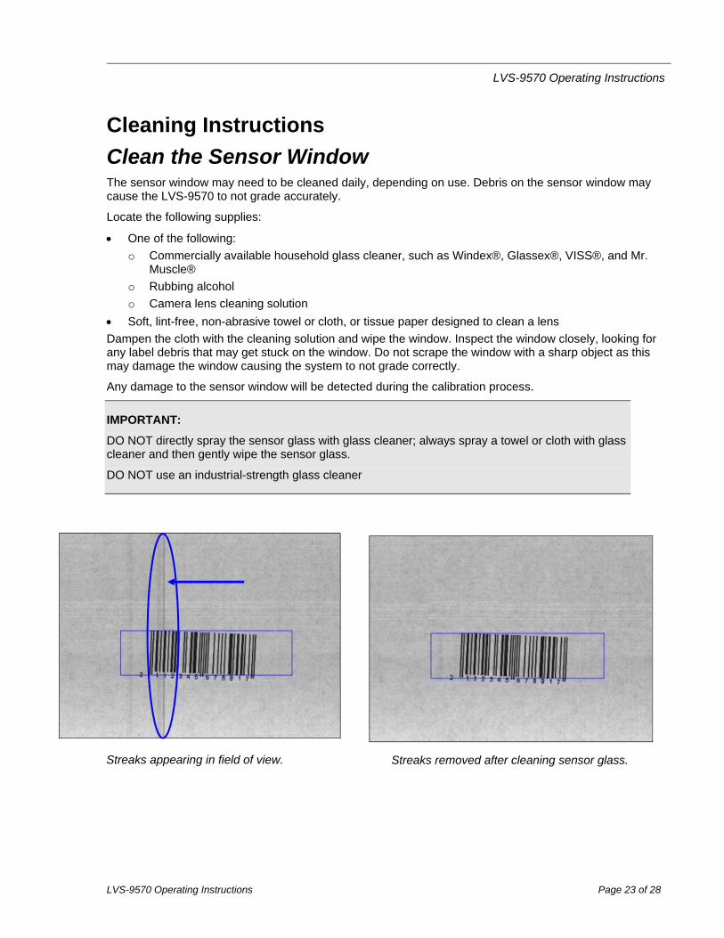
Streaks appearing in field of view. Streaks removed after cleaning sensor glass.
LVS-9570 Operating Instructions
LVS-9570 Operating Instructions Page 24 of 28
Clean the Rubber Roller The LVS-9570 rubber roller may need cleaning periodically, as it is important to keep the roller free of debris, adhesive buildup and other surface materials.
Locate the following supplies:
Dishwashing liquid
1 cup of water
Lint-free cloth
WARNING: Use only dishwashing liquid to clean the rubber roller. Do not clean the roller with alcohol, window cleaner or petroleum-based products, as this causes the rubber to crack.
Mix a few drops of dishwashing liquid into a cup of water and place a lint-free cloth into the solution until the cloth is saturated. Ring out the cloth so that no water drips from the cloth. Wipe down the rubber roller surface, removing any debris. As you wipe, turn the roller to clean the entire surface. Then, rinse out the cloth and wipe down the rubber surface again to remove any dishwashing liquid from the roller. Allow the roller to dry before using.
Window Scratches When the sensor window is scratched, it may cause a streak in the image. This streak may cause the barcode grade results to be distorted if the streak is located within the barcode image. When a scratch occurs, you may need to return the system to Omron Microscan (or your Omron Microscan distributor) for sensor replacement. Contact your Omron Microscan representative for more information.
LVS-9570 Operating Instructions
LVS-9570 Operating Instructions Page 25 of 28
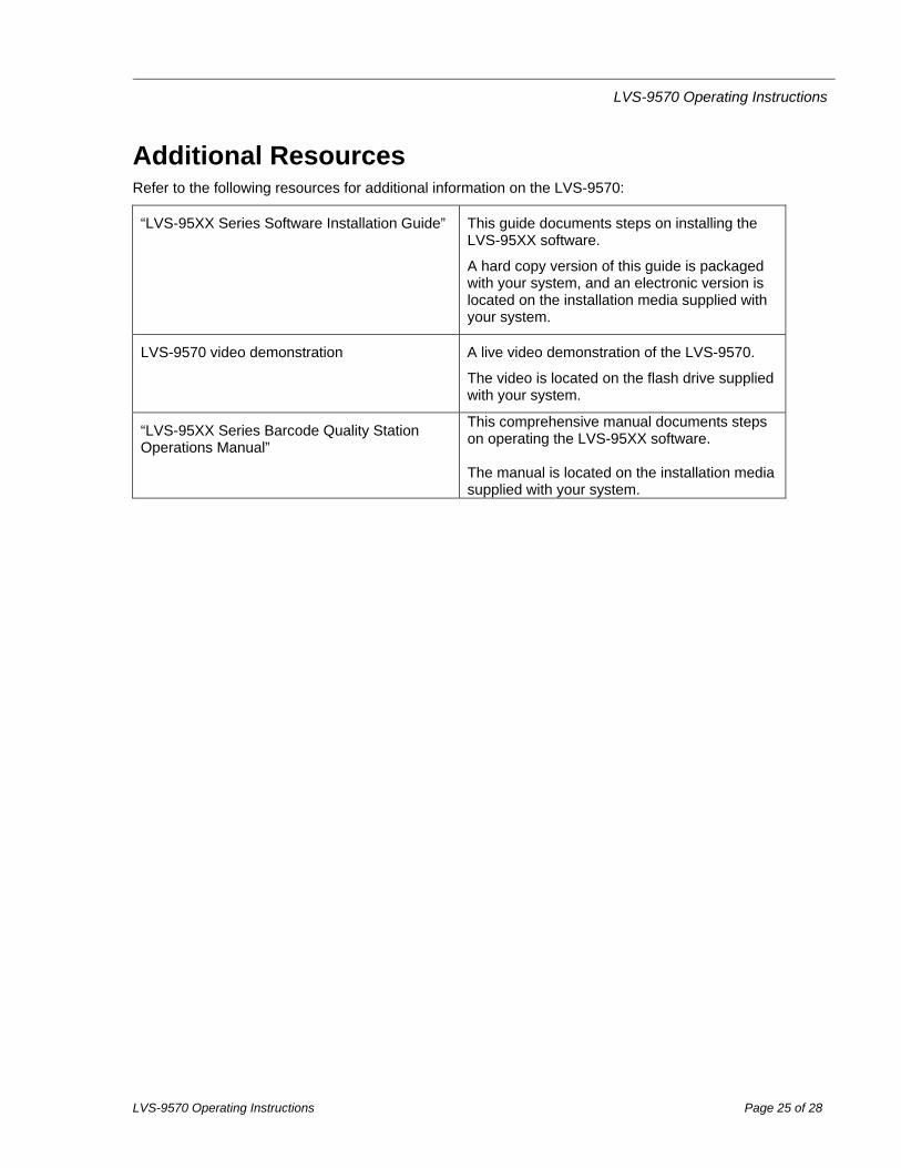
Additional Resources Refer to the following resources for additional information on the LVS-9570:
“LVS-95XX Series Software Installation Guide” This guide documents steps on installing the LVS-95XX software.
A hard copy version of this guide is packaged with your system, and an electronic version is located on the installation media supplied with your system.
LVS-9570 video demonstration A live video demonstration of the LVS-9570.
The video is located on the flash drive supplied with your system.
“LVS-95XX Series Barcode Quality Station Operations Manual”
This comprehensive manual documents steps on operating the LVS-95XX software. The manual is located on the installation media supplied with your system.

LVS-9570 Operating Instructions
LVS-9570 Operating Instructions Page 26 of 28
Engineering Specifications
Physical Properties
Height:
Verifier height 2.13” 54.10 mm
Total height including handle 4” 101.6 mm
Length 3.94” 100.08 mm
Width 6.56” 166.62 mm
Weight 2.3 pounds 1.04 kg
Line Scan Camera
400 DPI
Floating Sensor Head
Overall Scanning Width
5.4” (137.16 mm) in picket fence orientation
12.0” (305 mm) in ladder orientation
Minimum X-Dimension
1D (Narrow Bar Width): 8.8 mils (0.0088”) (0.223 mm)
2D (Cell Size): 12.5 mils (0.0125”) (0.317 mm)
Verification
1D and 2D codes
Minimum PC Requirements (PC Supplied by Customer)
Windows® XP Professional or Windows® 7 (Windows® Vista is not supported)
Intel® Core™ 2 Duo Processor (or equivalent)
2 GB RAM
800 x 600 Resolution
One available USB 2.0 port
Light Source
Red Light
660 nm
Inputs / Outputs
USB 2.0 port
Operating Temperature
10º C (50º F) to 30º C (86º F)
Storage Temperature
0º C (32º F) to 40º C (104º F)
Relative Humidity
20% to 70% (non-condensing)
Calibration
EAN/UPC Calibrated Conformance Test Card
21 CFR Part 11 Compliant-Ready
Specifications and photos subject to change.
LVS-9570 Operating Instructions
LVS-9570 Operating Instructions Page 27 of 28
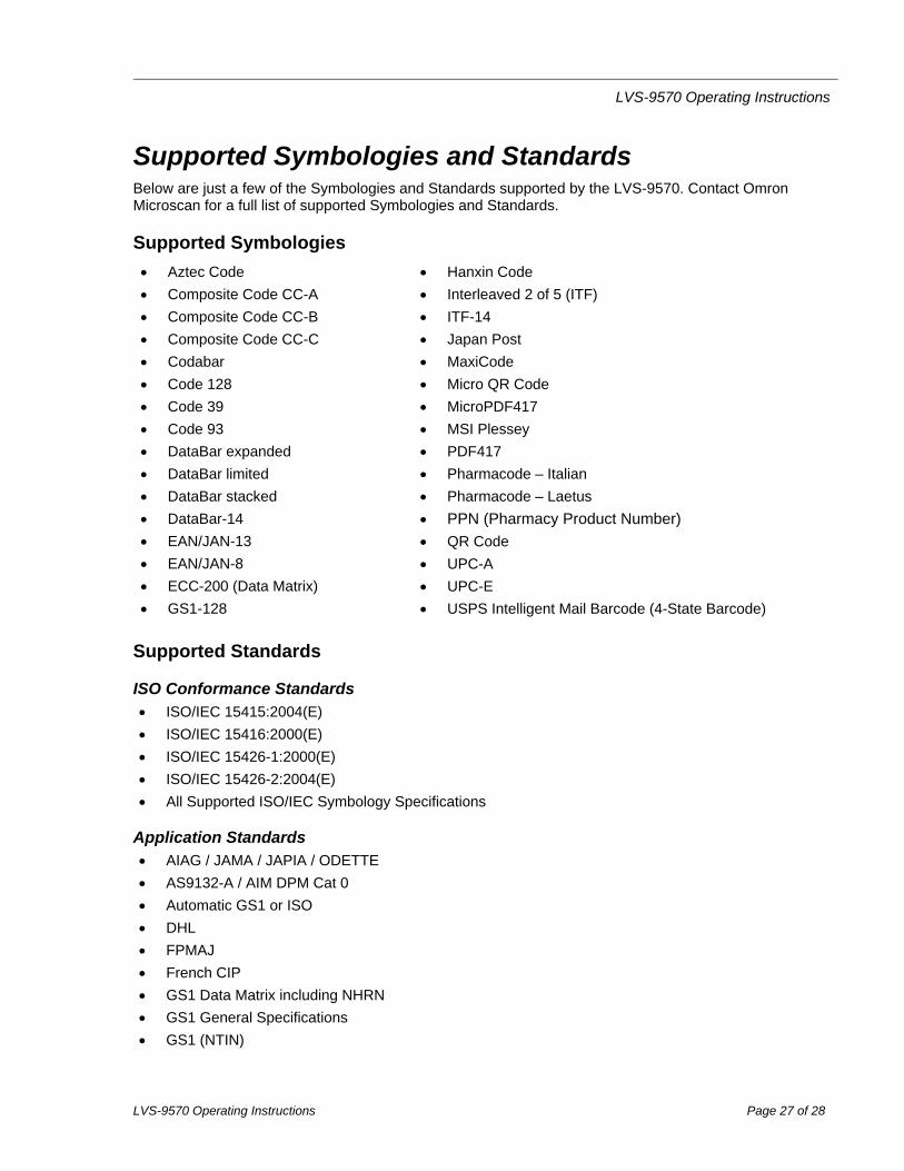
Supported Symbologies and Standards Below are just a few of the Symbologies and Standards supported by the LVS-9570. Contact Omron Microscan for a full list of supported Symbologies and Standards.
Supported Symbologies
Aztec Code
Composite Code CC-A
Composite Code CC-B
Composite Code CC-C
Codabar
Code 128
Code 39
Code 93
DataBar expanded
DataBar limited
DataBar stacked
DataBar-14
EAN/JAN-13
EAN/JAN-8
ECC-200 (Data Matrix)
GS1-128
Hanxin Code
Interleaved 2 of 5 (ITF)
ITF-14
Japan Post
MaxiCode
Micro QR Code
MicroPDF417
MSI Plessey
PDF417
Pharmacode – Italian
Pharmacode – Laetus
PPN (Pharmacy Product Number)
QR Code
UPC-A
UPC-E
USPS Intelligent Mail Barcode (4-State Barcode)
Supported Standards
ISO Conformance Standards ISO/IEC 15415:2004(E)
ISO/IEC 15416:2000(E)
ISO/IEC 15426-1:2000(E)
ISO/IEC 15426-2:2004(E)
All Supported ISO/IEC Symbology Specifications
Application Standards AIAG / JAMA / JAPIA / ODETTE
AS9132-A / AIM DPM Cat 0
Automatic GS1 or ISO
DHL
FPMAJ
French CIP
GS1 Data Matrix including NHRN
GS1 General Specifications
GS1 (NTIN)
LVS-9570 Operating Instructions
LVS-9570 Operating Instructions Page 28 of 28
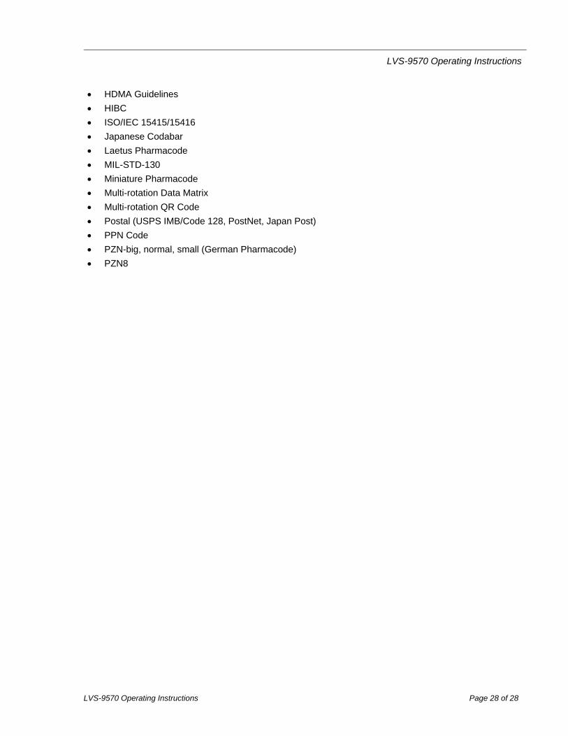
HDMA Guidelines
HIBC
ISO/IEC 15415/15416
Japanese Codabar
Laetus Pharmacode
MIL-STD-130
Miniature Pharmacode
Multi-rotation Data Matrix
Multi-rotation QR Code
Postal (USPS IMB/Code 128, PostNet, Japan Post)
PPN Code
PZN-big, normal, small (German Pharmacode)
PZN8