lrfd bridge design manual - louisiana - · pdf filebobby jindal governor : ana.gov bridge...
TRANSCRIPT
STATE OF LOUISIANA DEPARTMENT OF TRANSPORTATION AND DEVELOPMENT
P.O. Box 94245 Baton Rouge, Louisiana 70804-9245
BOBBY JINDAL
GOVERNOR
www.dotd.louisiana.gov Bridge Design Section
WILLIAM D. ANKNER, Ph.D.
SECRETARY
LRFD BRIDGE DESIGN MANUAL
Prepared by staff of the Bridge Design Section, under the direction of
Hossein Ghara, Bridge Design Engineer Administrator
First Edition
Version 2008.1 September 17, 2008
TABLE OF CONTENTS PREFACE MANUAL REVISION HISTORY CHAPTER 1 INTRODUCTION CHAPTER 2 GENERAL DESIGN FEATURES
CHAPTER 3 LOAD AND LOAD COMBINATIONS
CHAPTER 4 NOT PRESENTLY USED CHAPTER 5 SUPERSTRUCTURE CHAPTER 6 SUBSTRUCTURE

PREFACE
A target date of October 2007 has been set as a goal by AASHTO member states to reach their full transition to the Load and Resistance Factor Design (LRFD). Therefore, by October 2006 all LADOTD new bridge projects beginning with preliminary design should be designed by the latest edition of AASHTO LRFD Bridge Design Specifications. Designs for the reconstruction or rehabilitation of existing bridge structures should be completed with guidance from the Bridge Design Engineer. This manual documents policy on LRFD bridge design in Louisiana. It is a supplement to the latest edition of AASHTO LRFD Bridge Design Specifications, which designers should be adhere to unless directed otherwise by this document. Refer to the latest edition of LADOTD Bridge Design Manual (4th English Edition) for information not covered in this manual. Revisions to this manual shall be noted in the Manual Revision History sheet. Copies of this manual may be downloaded from the LA DOTD Website under Bridge Design. Copies of this manual may be obtained from: Louisiana Department of Transportation and Development Headquarters Administration Building – Room 100 1201 Capitol Access Road Baton Rouge, Louisiana 70802 Mail orders should be sent to: Louisiana Department of Transportation and Development General File Unit P.O. Box 94245 Baton Rouge, Louisiana 70802 Price - $10.00 per copy Any questions or comments on the contents of the manual should be directed to Bridge Design Section of Louisiana Department of Transportation and Development. Contact Number: (225) 379-1321 E-mail: [email protected]

MANUAL REVISION HISTORY
Edition Version Publication Date Summary of Changes 2006.1 September 1, 2006 Issue new manual. 1st
2008.1 September 17, 2008 Revised Preface, Manual Revision History, Chapter 3, Chapter 5 and Chapter 6
CHAPTER
1 I N T R O D U CT I O N
TABLE OF CONTENTS
IMPLEMENTATION..................................................................................................................................... 1 PURPOSE ................................................................................................................................................... 1 LIMIT STATES ............................................................................................................................................ 1
1 (i)
INTRODUCTION
IMPLEMENTATION
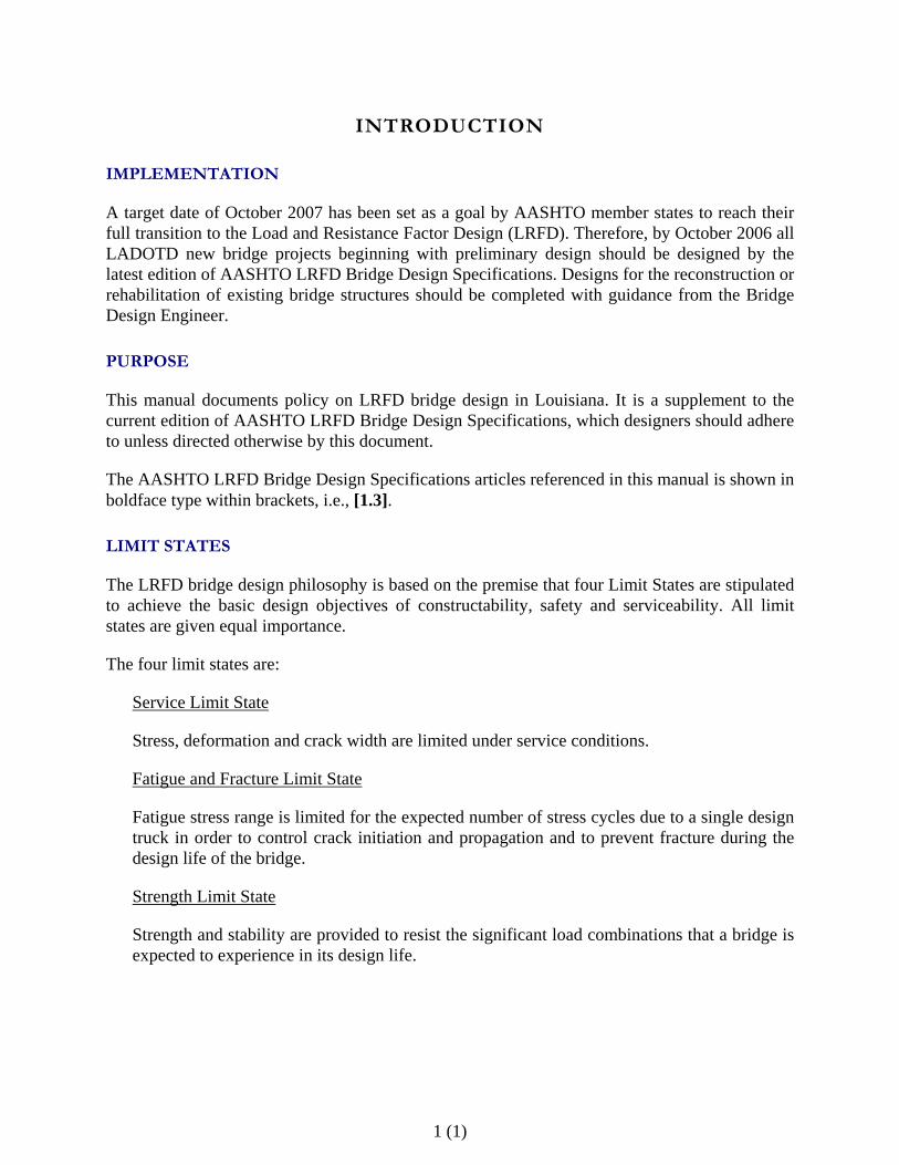
A target date of October 2007 has been set as a goal by AASHTO member states to reach their full transition to the Load and Resistance Factor Design (LRFD). Therefore, by October 2006 all LADOTD new bridge projects beginning with preliminary design should be designed by the latest edition of AASHTO LRFD Bridge Design Specifications. Designs for the reconstruction or rehabilitation of existing bridge structures should be completed with guidance from the Bridge Design Engineer.
PURPOSE
This manual documents policy on LRFD bridge design in Louisiana. It is a supplement to the current edition of AASHTO LRFD Bridge Design Specifications, which designers should adhere to unless directed otherwise by this document.
The AASHTO LRFD Bridge Design Specifications articles referenced in this manual is shown in boldface type within brackets, i.e., [1.3].
LIMIT STATES
The LRFD bridge design philosophy is based on the premise that four Limit States are stipulated to achieve the basic design objectives of constructability, safety and serviceability. All limit states are given equal importance.
The four limit states are:
Service Limit State
Stress, deformation and crack width are limited under service conditions.
Fatigue and Fracture Limit State
Fatigue stress range is limited for the expected number of stress cycles due to a single design truck in order to control crack initiation and propagation and to prevent fracture during the design life of the bridge.
Strength Limit State
Strength and stability are provided to resist the significant load combinations that a bridge is expected to experience in its design life.
1 (1)

Extreme Event Limit State
Structures are proportioned to resist collapse due to extreme events, such as, a major earthquake, flood, ice flow, collision by a vessel, etc.
Equation [1.3.2.1-1] of AASHTO LRFD Bridge Design Specifications, unless specified otherwise, must be satisfied for each limit state.
Ση i γ i⋅ Qi⋅ φRn≤ Rr
in which:
For loads for which a maximum value of γi is appropriate:
95
For loads for which a minimum value of γi is appropriate:
η i η D η R⋅ η I⋅ 0.≥
η i1
η D η R⋅ η I⋅1.0≤
where ηi, γi, Qi, φ, Rn, Rr and ηD are defined in section [1.3.2].
The value of the Redundancy Factor [1.3.4], ηR, should be as follows:
For the strength limit state:
ηR = 1.05 For Pile Bents with 3 piles or less
For Column Bents with 2 columns or less
For Fracture-Critical members
ηR = 1.00 For other elements and components
For all other limit states:
ηR = 1.00
The value of Ductility, ηD, shall follow the LRFD Specifications [1.3.3].
1 (2)

1 (3)
The value of the Operational Importance Factor [1.3.5], ηI, should be as follows:
ηI = 1.05 For NHS bridges or any bridges with truck traffic > 2500 per day
ηI = 1.05 For all moveable bridges
ηI = 0.95 For Off - System bridges with ADT < 3000
ηI = 1.0 For other bridges
Bridges on National Highway System are defined as NHS bridges. The LA DOTD Office of Planning and Programming Section may be contacted to determine National Highway System routes in Louisiana. Bridges on parish roads are defined as Off-System bridges.
2 (i)
G E N E R A L D E S I G N F E A T U R E S
TABLE OF CONTENTS DEFLECTION CRITERIA ....................................................................................................................... 1
CHAPTER
2
2 (1)
DEFLECTION CRITERIA
Optional criteria for span-to-depth ratio in Section [2.5.2.6.3] of AASHTO LRFD Bridge Design Specifications should be applied for the deflection control of the structures included in [Table 2.5.2.6.3-1].
Section [2.5.2.6.2] of AASHTO LRFD Bridge Design Specifications should be applied for the deflection control of orthotropic decks, precast reinforced concrete three-sided structures, metal grid decks, light weight metal and concrete bridge decks, and structures that are not included in [Table 2.5.2.6.3-1] or not meeting the minimum depth defined in [Table 2.5.2.6.3-1].
Approval from the Bridge Design Engineer is required if the deflection of a structure does not meet the criteria in Section [2.5.2.6.2] or [2.5.2.6.3].
CHAPTER
3 L O A D A N D L O A D C O M B I N A T I O N S
TABLE OF CONTENTS LOAD........................................................................................................................................................... 1
DESIGN VEHICULAR LIVE LOAD .............................................................................................................. 1 LOUISIANA SPECIAL DESIGN VEHICLES ..................................................................................................... 1 VEHICULAR COLLISION FORCE ................................................................................................................ 1 STORM SURGE AND WAVE FORCES............................................................................................................ 1
LOAD FACTORS AND LOAD COMBINATIONS................................................................................ 2
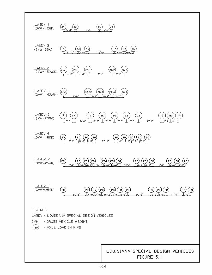
FIGURE 3.1………………………………………………………………………………………………..3
3 (i)
LOAD
DESIGN VEHICULAR LIVE LOAD
Section [3.6] of AASHTO LRFD Bridge Design Specifications shall be applied for the design vehicular live load. Vehicular live loading on the roadway of bridges or incidental structures shall use the HL-93 live load as per section [3.6.1.2]. The design vehicular live load shall be applied per section [3.6.1.3]. Multiple presence factors shall be applied per section [3.6.1.1.2]. Dynamic load allowance shall be applied per section [3.6.2].
LOUISIANA SPECIAL DESIGN VEHECLES
The Louisiana Special Design Vehicles specified in Figure 3.1 shall be included in the design for Strength II limit state per section [3.4].
VEHICULAR COLLISION FORCE
Vehicular collision force shall be applied as per section [3.6.5]. The structures should be protected from vehicular collision as per section [3.6.5.1]. Otherwise, the structures should be designed for the collision force specified in section [3.6.5.2].
STORM SURGE AND WAVE FORCES
Storm surge and wave forces shall be developed based on the latest “AASHTO Guide Specification for Bridges Vulnerable to Coastal Storms”.
3 (1)
3 (2)
LOAD FACTORS AND LOAD COMBINATIONS
Load factors and load combinations specified in [Table 3.4.1-1] and [Table 3.4.1-2] of AASHTO LRFD Bridge Design Specifications shall be followed except for extreme events with scour and storm surge forces. For extreme events with scour, the Extreme Event III to VI as defined in page 118 of NCHRP Report 489, “Design of Highway Bridges for Extreme Events,” shall be followed. For extreme events with storm surge and wave, the latest “AASHTO Guide Specification for Bridges Vulnerable to Coastal Storms” shall be followed.
CHAPTER
5 S U P E R S T R U C T U R E
TABLE OF CONTENTS BRIDGE RAILING .................................................................................................................................... 1
DECK DESIGN........................................................................................................................................... 2 DESIGN METHOD ...................................................................................................................................... 2 EMPIRICAL DECK DESIGN......................................................................................................................... 2
Material ................................................................................................................................................ 2 Curing Method ..................................................................................................................................... 2 Deck Thickness .................................................................................................................................... 2
STEEL GIRDERS ...................................................................................................................................... 3
PRESTRESSED CONCRETE GIRDERS ............................................................................................... 3
5(i)
BRIDGE RAILING
The following bridge railing test levels TL-1 to TL-6 are included in Section [13.7.2] of the 3rd
edition of AASHTO LRFD Bridge Design Specifications. Design forces for the testing levels are defined in [Table A13.2-1].
TL-1 Test Level One
Taken to be generally acceptable for work zones with low posted speeds and very low volume, low speed local streets.
TL-2 Test Level Two (Equivalent to PL-11)
Taken to be generally acceptable for work zones and most local and collector roads with favorable site conditions as well as a small number of heavy vehicles is expected and posted speeds are reduced.
TL-3 Test Level Three
Taken to be generally acceptable for a wide range of high speed arterial highways with very low mixture of heavy vehicles and with favorable site conditions.
TL-4 Test Level Four (Equivalent to PL-22)
Taken to be generally acceptable for the majority of applications on high-speed highways, freeways, expressways, and Interstate highways with a mixture of trucks and heavy vehicles.
TL-5 Test Level Five (Equivalent to PL-33)
Taken to be generally acceptable for the same applications as TL-4 and where large trucks make up a significant portion of the average daily traffic or when unfavorable site conditions justify a higher level of rail resistance.
TL-6 Test Level Six
Taken to be generally acceptable for applications where tanker-type trucks or similar high center of gravity vehicles are anticipated, particularly along with unfavorable site conditions.
The selection criteria of bridge railings and the railing details included in Chapter 5 of LADOTD Bridge Design Manual (4th English Edition) shall be followed.
1 PL-1 is defined on page 5(3) of LADOTD Bridge Design Manual (4th English Edition). 2 PL-2 is defined on page 5(3) of LADOTD Bridge Design Manual (4th English Edition). 3 PL-3 is defined on page 5(3) of LADOTD Bridge Design Manual (4th English Edition).
5(1)
DECK DESIGN
DESIGN METHOD
Both Empirical Deck Design and Traditional Design Method as specified in Section 9 of AASHTO LRFD Bridge Design Specifications can be applied to deck design. The Empirical Deck Design shall not be applied to the overhangs. The reinforcement spacing in the deck shall not exceed seven inches.
EMPIRICAL DECK DESIGN
The following provisions shall be applied in addition to the requirements specified in AASHTO Specifications for the Empirical Deck Design:
MATERIAL
Concrete Class AA(M) with minimum design concrete strength, fc’, of 4000 psi shall be specified
for all bridges. All reinforcing steel shall be grade 60 bars, fy = 60 ksi.
CURING METHOD
Bridge deck shall be fully cast-in-place and water cured. Optional Span Details will not be permitted using the empirical deck design.
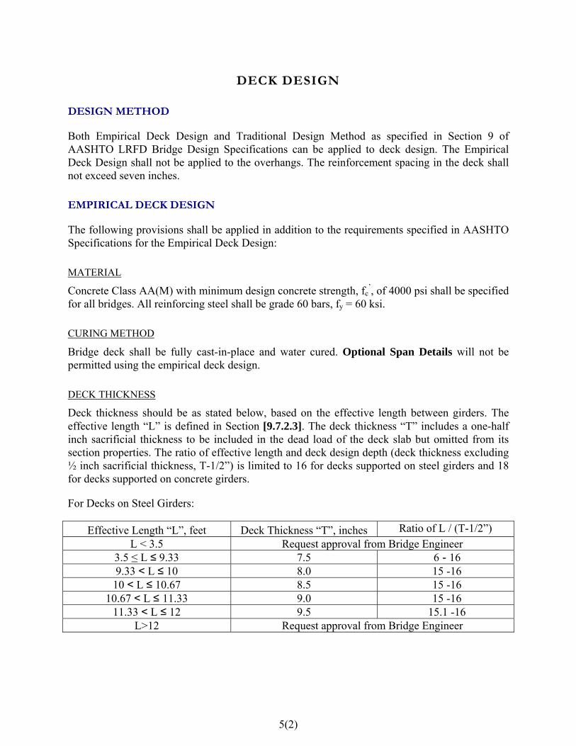
DECK THICKNESS
Deck thickness should be as stated below, based on the effective length between girders. The effective length “L” is defined in Section [9.7.2.3]. The deck thickness “T” includes a one-half inch sacrificial thickness to be included in the dead load of the deck slab but omitted from its section properties. The ratio of effective length and deck design depth (deck thickness excluding ½ inch sacrificial thickness, T-1/2”) is limited to 16 for decks supported on steel girders and 18 for decks supported on concrete girders.
For Decks on Steel Girders:
Effective Length “L”, feet Deck Thickness “T”, inches Ratio of L / (T-1/2”) L < 3.5 Request approval from Bridge Engineer
3.5 ≤ L ≤ 9.33 7.5 6 - 16 9.33 < L ≤ 10 8.0 15 -16 10 < L ≤ 10.67 8.5 15 -16
10.67 < L ≤ 11.33 9.0 15 -16 11.33 < L ≤ 12 9.5 15.1 -16
L>12 Request approval from Bridge Engineer
5(2)
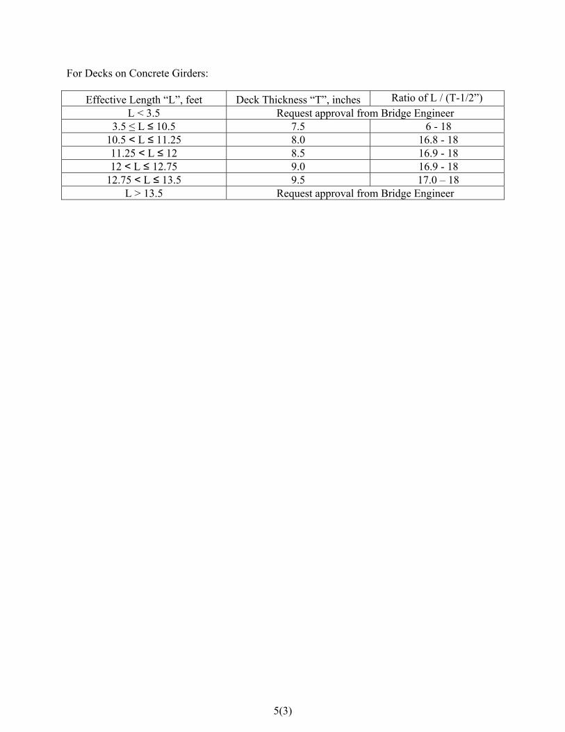
For Decks on Concrete Girders:
Effective Length “L”, feet Deck Thickness “T”, inches Ratio of L / (T-1/2”) L < 3.5 Request approval from Bridge Engineer
3.5 ≤ L ≤ 10.5 7.5 6 - 18 10.5 < L ≤ 11.25 8.0 16.8 - 18 11.25 < L ≤ 12 8.5 16.9 - 18 12 < L ≤ 12.75 9.0 16.9 - 18
12.75 < L ≤ 13.5 9.5 17.0 – 18 L > 13.5 Request approval from Bridge Engineer
5(3)
STEEL GIRDERS
Simple and continuous steel girders shall be designed for composite action [6.10.1.2]. Shear connectors shall be placed in both positive and negative moment regions. If the design of composite sections over negative moment regions is not feasible due to top flange fatigue control, non-composite sections may be utilized in this region with the approval of Bridge Engineer.
PRESTRESSED CONCRETE GIRDERS
DESIGN METHOD
Prestressed girders shall be made continuous for the maximum practical length to eliminate expansion joints. The prestress girders shall be designed as simple span girders for positive moment, without regard to live load continuity. The prestress girders shall be designed to account for live load continuity for shear and negative moment design. Other design methods may be allowed with approval of Bridge Engineer. When prestress girders are used in applications where they are made continuous for live load, the minimum prestressed concrete girder age shall be 90 days when the continuity is established.
BEARING PAD DESIGN
Elastomeric bearing pads as shown on the standard Misc. Span and Girder Details are currently designed in accordance with AASHTO Standard Specifications for Highway Bridges (1996). Those details can be used with LRFD design if the following conditions are met.
1) The design spans do not exceed 85 feet, and utilize girders not heavier than Type III AASHTO girders.
2) The length of concrete unit contributing to horizontal movement is limited to 140 feet in length.
Any LRFD design applications not meeting the above conditions will require a total redesign of bearing pad.
5(4)
CHAPTER
6 S U B S T R U C T U R E
TABLE OF CONTENTS GENERAL................................................................................................................................................... 1
DRIVEN PILE ............................................................................................................................................ 2 PILE DESIGN LOAD .................................................................................................................................... 2 RESISTANCE FACTOR................................................................................................................................. 3 PILE DESIGN .............................................................................................................................................. 3
Simplified method ................................................................................................................................ 3 Table 6.1 Maximum Factored Axial Compresive Load Allowed ........................................................ 4 Detail Method....................................................................................................................................... 5
PILE DATA SHEETS .................................................................................................................................... 6
6(i)

GENERAL
This chapter supplements AASHTO LRFD Bridge Design Specifications Section 10 and provides general LRFD guidance on the design of specific bridge substructure components. The Bridge Design Engineer and Geotechnical engineer shall work together in the selection and design of the foundation system.
Refer to the latest edition of LADOTD Bridge Design Manual (4th English Edition) Chapter 6 for information not covered here.
6(1)
DRIVEN PILE
PILE DESIGN LOAD
Pile design loads including factored and service load shall be determined according to AASHTO LRFD Bridge Design Specifications for all applicable limit states, including strength, service, and extreme limit states unless specified otherwise.
The design of pile foundations at the strength limit shall consider the following:
1) Compression resistance for single piles,
2) Compression resistance for pile groups,
3) Uplift resistance for single piles,
4) Uplift resistance for pile groups,
5) Pile punching failure into a weaker stratum below the bearing stratum,
6) Lateral resistance for single piles and pile groups, and
7) Constructability, including pile drivability.
The design of pile foundations at the service limit state shall include the following:
1) Settlements
2) Horizontal movements
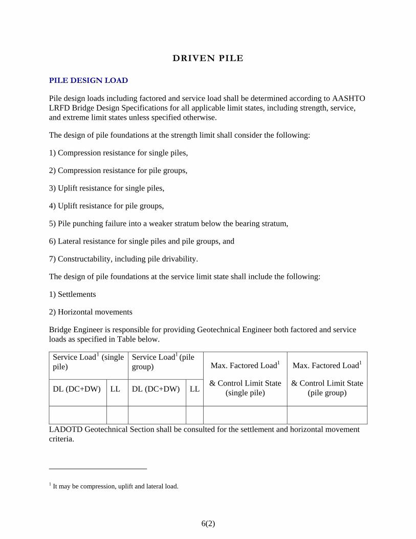
Bridge Engineer is responsible for providing Geotechnical Engineer both factored and service loads as specified in Table below.
Service Load1 (single pile)
Service Load1 (pile group)
DL (DC+DW) LL DL (DC+DW) LL
Max. Factored Load1
& Control Limit State (single pile)
Max. Factored Load1
& Control Limit State (pile group)
LADOTD Geotechnical Section shall be consulted for the settlement and horizontal movement criteria.
1 It may be compression, uplift and lateral load.
6(2)

RESISTANCE FACTOR
The resistance factors for the driven piles shall be determined by Geotechnical Engineer in accordance with [Table 10.5.5.2.3-1] and [Table 10.5.5.2.3-2] of AASHTO LRFD Bridge Design Specifications and shall consult with LADOTD Geotechnical Section for any additional guidance. Approval from LADOTD Geotechnical Section and Bridge Design Section is required if a resistance factor higher than 0.7 is used with a load test.
PILE DESIGN
The design of driven pile foundation shall follow Section [10.7] of the AASHTO LRFD Bridge Design Specifications unless specified otherwise.
For typical pile bents with small lateral load (no marine vessel collision loads) for non-critical small projects, a simplified method as specified below is allowed.
For consultant projects, the design method to be used for pile design shall be specified in the contract documents.
SIMPLIFIED METHOD
The simplified method as specified here can only be applied to the typical pile bents with small lateral load (no marine vessel collision loads) for non-critical small projects.
The general design steps of the simplified method are:
1) Assume pile cap size, number and size of piles to be used.
2) Determine LRFD factored axial compression load considering dead and live loads only.
3) The maximum factored compression pile load shall fall within the range shown in the Table 6.1 on page 6(4). The maximum slenderness ratio L/d shall be less than or equal to 20. L is the unsupported pile length in feet. The unsupported length is measured down below the channel bottom or ground line accounting for estimated scour, if appropriate (5 feet minimum), plus a distance to the assumed point of fixity. In general, point of fixity can be assumed at 5 feet below scour or ground line.
4) Adjust piles and cap size and recompute if needed. Design cap for required reinforcement.
5) Geotechnical Engineer computes the final pile length based on the pile loads submitted by structural engineer applying appropriate pile resistance factors. LADOTD Geotechnical Section shall be consulted for the guidance on the geotechnical design and pile resistance factor determination.
6(3)
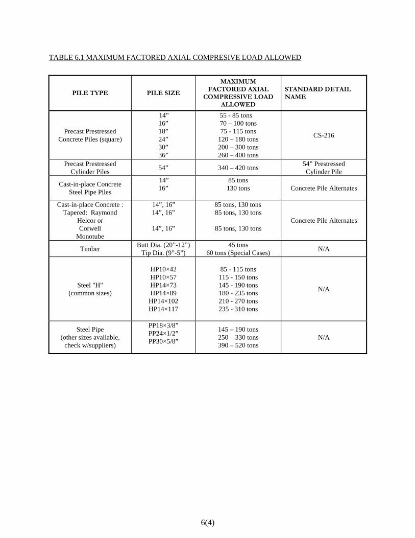
TABLE 6.1 MAXIMUM FACTORED AXIAL COMPRESIVE LOAD ALLOWED
PILE TYPE PILE SIZE MAXIMUM
FACTORED AXIAL COMPRESSIVE LOAD
ALLOWED
STANDARD DETAIL NAME
Precast Prestressed Concrete Piles (square)
14” 16” 18” 24” 30” 36”
55 - 85 tons 70 – 100 tons 75 - 115 tons
120 – 180 tons 200 – 300 tons 260 – 400 tons
CS-216
Precast Prestressed Cylinder Piles 54” 340 – 420 tons 54” Prestressed
Cylinder Pile
Cast-in-place Concrete Steel Pipe Piles
14” 16”
85 tons 130 tons
Concrete Pile Alternates
Cast-in-place Concrete : Tapered: Raymond
Helcor or Corwell
Monotube
14”, 16” 14”, 16”
14”, 16”
85 tons, 130 tons 85 tons, 130 tons
85 tons, 130 tons
Concrete Pile Alternates
Timber Butt Dia. (20”-12”) Tip Dia. (9”-5”)
45 tons 60 tons (Special Cases) N/A
Steel "H" (common sizes)
HP10×42 HP10×57 HP14×73 HP14×89
HP14×102 HP14×117
85 - 115 tons
115 - 150 tons 145 - 190 tons 180 - 235 tons 210 - 270 tons 235 - 310 tons
N/A
Steel Pipe (other sizes available,
check w/suppliers)
PP18×3/8” PP24×1/2” PP30×5/8”
145 – 190 tons 250 – 330 tons 390 – 520 tons
N/A
6(4)
DETAILED METHOD
When specified by the bridge engineer or called for by this manual, a detailed analysis of the foundation system shall be performed and pile loads shall be determined for all applicable limit states. The structural pile capacity (ΦPn - ΦMn Interaction Diagram) shall be calculated based on the slenderness of the pile and the specific soil conditions. The pile design loads including axial load and moments shall be within 75% of the structural capacity of the piles.
The general design steps are described as follows:
Case 1 – Substructure Subject to Small Pile Load (No Marine Vessel Loads)
1) Assume preliminary foundation element size, number and size of piles and pile length.
2) Model the bent using STAAD or other equivalent software. Determine the preliminary depth of the pile fixity point below ground using the equations in Section [10.7.3.13.4] of AASHTO LFRD Bridge Design Specifications. Determine factored pile loads including axial, lateral and moments for all limit states.
3) Use LPILE or FB-pier software to model the soil-pile interaction to determine the depth of the pile fixity point. Coordination with Geotechnical Engineer is needed so that the soil parameters are interpreted and input correctly by the structural engineer.
4) Revise the bent model with the new depth of the fixity point and recompute the pile loads.
5) Compute the pile structural capacity (ΦPn - ΦMn Interaction Diagram) for the slenderness of the pile using applicable software, such as PCI prestressed concrete pile design Excel file, RC-pier or FB-Pier, etc. The pile loads shall be within 75% of the structural capacity of the piles (ΦPn - ΦMn Interaction Diagram). Design cap for required reinforcement.
6) Geotechnical Engineer computes the final pile length based on the pile loads submitted by structural engineer and appropriate pile resistance factors. LADOTD Geotechnical Section shall be consulted for the guidance on the geotechnical design and pile resistance factors determination.
Case 2 – Substructure Subject to Marine Vessel Collision Loads or High Lateral Loads
Same steps as Case 1 except the soil-structure interaction analysis will require the use of FB-Pier software (Version 4.09 or higher).
6(5)

6(6)
PILE DATA SHEETS
The following pile load information shall be included in the pile data sheet as minimum:
Factored Load Pile Resistance Factor (Φ)
Compression Uplift Compression Uplift
Scour Zone Resistance
Ultimate Pile Compression Capacity
Required Tip Elev.
Ultimate Pile Comp. Capacity = Factored Load / Pile Resistance Factor + Scour Zone Resistance
If a load test is to be performed, Geotechnical Engineer shall supply the target test load.