december 2010 lrfd bridge design 1-1 - minnesota … · · 2016-08-12december 2010 lrfd bridge...
TRANSCRIPT
DECEMBER 2010 LRFD BRIDGE DESIGN 1-1
This section contains general information about the manual along with a general description of the Bridge Office and its procedures. This manual contains Mn/DOT Bridge Office policies and procedures for the design, evaluation, and rehabilitation of bridges. Except where noted, the design provisions herein employ the Load and Resistance Factor Design (LRFD) methodology set forth by AASHTO. Mn/DOT utilizes a decimal numbering system to classify documents. The “5” before the hyphen represents a publication related to engineering. The “300” series of documents is assigned to the Bridge Office; the “90” series indicates that this is a “Manual”. The last digit “2” specifies that the subject matter of the document is “Design”. The original bridge design manual, numbered 5-392, provided guidance for the design of highway structures in Minnesota in accordance with allowable stress design methods. Subsequently, it has received periodic updates as design methods have changed. This version of the Bridge Design Manual contains significant changes. It presents Mn/DOT’s design practices in conformance with a new design methodology, Load and Resistance Factor Design (LRFD), and also contains fifteen comprehensive design examples. Use of this manual does not relieve the design engineer of responsibility for the design of a bridge or structural component. Although Bridge Office policy is presented here for numerous situations, content of the manual is not intended to be exhaustive. Therefore, use of this manual must be tempered with sound engineering judgment. After this introductory material, the manual contains material arranged around the following section headings. To simplify locating material, section numbers correspond to those used in the LRFD specifications: 1) Introduction 2) General Design and Location Features 3) Loads and Load Factors 4) Structural Analysis and Evaluation 5) Concrete Structures 6) Steel Structures 7) Reserved 8) Wood Structures 9) Decks and Deck Systems 10) Foundations 11) Abutments, Piers, and Walls
1. INTRODUCTION
1.1.1 Material Contained in Manual 5-392
1.1 Overview of Manual 5-392
DECEMBER 2010 LRFD BRIDGE DESIGN 1-2
12) Buried Structures 13) Railings 14) Joints and Bearings 15) Ratings
Memos This manual will be updated multiple times each year as procedures are updated and new information becomes available. Current files for each section of the manual are available on the Bridge Office Web site at: http://www.dot.state.mn.us/bridge/ . Each section of the manual contains general information at the start of the section. Design examples (if appropriate) are located at the end of each section. The general content is divided into subsections that are identified with numerical section labels in the left margin. Labels for design example subsections are identified with alphanumeric labels in the left hand margin. The left hand margin also contains references to LRFD Design Specification Articles, Equations, and Tables. These references are enclosed in square brackets. Within the body of the text, references to other sections of this manual are directly cited (e.g. Section 10.1). References to the LRFD Specifications within the main body of the text contain a prefix of: LRFD. A bridge is defined under Minnesota Rule 8810.8000 Subp. 2 as a structure “having an opening measured horizontally along the center of the roadway of ten feet or more between undercopings of abutments, between spring line of arches, or between extreme ends of openings for multiple boxes. Bridge also includes multiple pipes where the clear distance between openings is less than half of the smaller contiguous opening.” In accordance with Minnesota Statute 15.06 Subd. 6, the Commissioner of Transportation has delegated approval authority for State Preliminary Bridge Plans, and State, County and City Final Bridge Plans to the State Bridge Engineer. Plans for all bridge construction or reconstruction projects located on the Trunk Highway System, and plans on County or City highways funded fully or in part by state funds shall be approved by the State Bridge Engineer.
1.1.2 Updates to Manual 5-392
1.2 General Bridge Information
1.1.3 Format of Manual References
DECEMBER 2010 LRFD BRIDGE DESIGN 1-3
The Bridge Office is responsible for conducting all bridge and structural design activities and for providing direction, advice, and services for all bridge construction and maintenance activities. The responsibilities include: Providing overall administrative and technical direction for the office. Reviewing and approving all preliminary and final bridge plans
prepared by the office and consultants. Representing the Department in bridge design, construction and
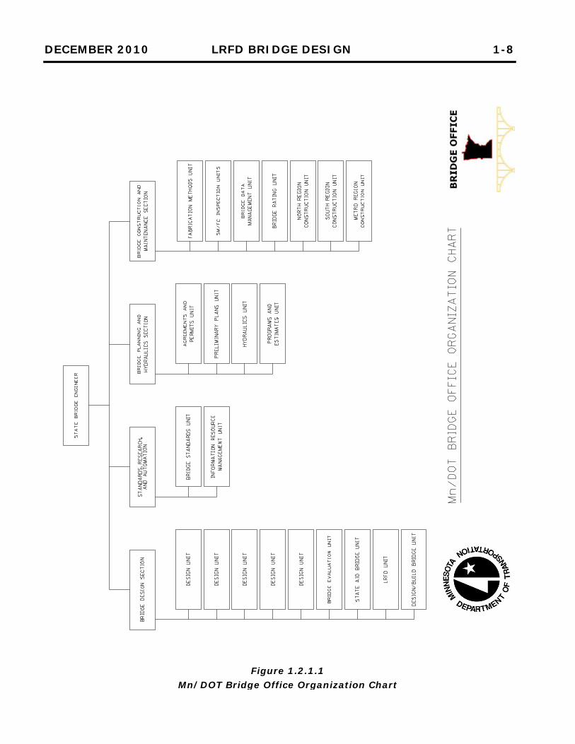
maintenance matters with other agencies. The Office is under the direction of the State Bridge Engineer. It is composed of sections and units as shown on the organizational chart (Figure 1.2.1.1). Each of these subdivisions with their principal functions is listed as follows: 1) Bridge Design Section
Responsible for the design, plans, and special provisions activities for bridges and miscellaneous transportation structures. a) Design Unit
i) Designs and drafts bridge design plans for new bridge construction or in-place bridge repairs.
ii) Reviews bridge plans prepared by consulting engineers. iii) Prepares special provisions for bridge plans. iv) Designs and drafts plans for miscellaneous transportation
structures. v) Provides technical assistance, designs, and plans for special
bridge and structural problems. vi) Assists the Districts and other offices in solving bridge and
other structure construction issues. b) Bridge Evaluation Unit
i) Provides review of fracture critical inspection reports and recommends reevaluation of rating as needed.
ii) Performs design or rating for special non-bridge structures. iii) Analyzes unusual or atypical bridge structures. iv) Responds to and prepares plans for repairs and retrofits to
bridges damaged by bridge hits. c) State Aid Bridge Unit
i) Assists local agencies in the planning, designing, and construction of bridge projects.
ii) Reviews preliminary and final bridge plans for counties, townships, and municipalities within the State of Minnesota which receive State and/or Federal Aid Funds for bridge construction. The bridge plan reviews are conducted to assure they comply with AASHTO LRFD Design Specifications,
1.2.1 Bridge Office
DECEMBER 2010 LRFD BRIDGE DESIGN 1-4
Mn/DOT LRFD Bridge Design Manual, applicable Mn/DOT Technical Memorandums, Mn/DOT Standard Specifications for Construction, applicable Mn/DOT Bridge Special Provisions, and all Mn/DOT policies.
iii) Serves to assist in the planning and review of miscellaneous structures for local agencies. These structures include, but are not limited to, pedestrian bridges, boardwalks, retaining walls, culverts, parking ramps, park buildings, skyways, and stair towers.
iv) Provides technical assistance to local agencies and their consultants in the implementation of new, innovative, efficient and cost effective bridge systems.
v) Provides assistance as requested by the local agencies and/or their consultants, with the preparation, setup, and delivery of local bridge training. The training can encompass all aspects of local bridges, such as planning, design, construction, load rating, and inspection.
d) LRFD Unit i) Maintains LRFD Bridge Design Manual. ii) Provides support to office and consulting engineers concerning
LRFD issues. e) Design/Build Unit
i) Prepares procurement documents for design/build projects. ii) Provides design oversight for design/build projects.
2) Standards, Research, and Automation Section
Responsible for development of standards and design aids, managing research studies pertaining to bridges, and supporting computing needs in the office. a) Bridge Standards Unit
i) Provides design aids and standards for the office and for consultants, counties, and cities.
ii) Provides oversight for research projects, which involve the Bridge Office.
b) Information Resource Management Unit i) Coordinates the development of computer programs with data
processing systems. ii) Supports computer users throughout the office and manages
the local area network. iii) Maintains design and drafting software and provides support
to users in the office.
DECEMBER 2010 LRFD BRIDGE DESIGN 1-5
3) Bridge Planning and Hydraulics Section Responsible for program, cost estimates, preliminary bridge plan activities for Trunk Highways and review of state aid bridges. Also, responsible for providing statewide hydraulic engineering services that include design, construction and maintenance activities. In addition, the section provides leadership in the development and implementation of hydraulic automation technology, establishes policy pertaining to hydrology and hydraulics, prepares design aids, provides client training, participates in research projects, and represents the department on state and national committees. a) Agreements and Permits Unit
i) Selects and negotiates with consulting engineers and administers engineering agreements for the preparation of bridge plans.
ii) Provides liaison between the Bridge Office and the consulting engineer retained to prepare bridge plans.
iii) Coordinates public and private utility requirements for bridges.
b) Preliminary Plans Unit i) Conducts preliminary studies from layouts and develops
preliminary bridge plans. ii) Provides liaison with District and Central Office road design
through the design stage. iii) Obtains required permits from other agencies for bridges.
c) Hydraulics Unit i) Develops and maintains Drainage Manual, standards and
specifications related to drainage design and products for use by Mn/DOT and other agencies.
ii) Provides technical assistance to Districts on all aspects of drainage design.
iii) Provides bridge and culvert waterway designs for trunk highway projects. Conducts channel surveys for requested waterway bridges.
iv) Analyzes and evaluates bridges for scour, monitors bridges for scour during floods, and provides training and support for scour monitoring.
v) Provides technical assistance to counties and municipalities upon request.
vi) Provides training in hydrology and hydraulics. vii) Reviews and prorates cost of storm drains on the municipal
and county state aid system. viii) Develops, implements, and supports a hydraulic information
system to facilitate the sharing of hydraulic data among all users and stakeholders.
DECEMBER 2010 LRFD BRIDGE DESIGN 1-6
d) Programs and Estimates Unit i) Prepares preliminary, comparative, and final cost estimates. ii) Maintains and provides current program and plan status
records. 4) Bridge Construction and Maintenance Section
Responsible for bridge construction and maintenance specifications, and bridge construction and maintenance advisory service activities to the office and to the job site. a) Construction and Maintenance Unit; North, Metro and South
Regions i) Provides construction and maintenance advisory service to
bridge construction and maintenance engineers in the field. ii) Writes bridge construction and maintenance specifications,
manuals and bulletins. iii) Writes and maintains the file of standard current special
provisions for bridge construction and maintenance. iv) Performs preliminary, periodic and final review of bridge
construction and maintenance projects and makes recommendations.
v) Reviews bridge plans and special provisions prior to lettings and makes constructability recommendations.
vi) Aids municipal and county engineers with bridge construction and maintenance problems, upon request.
vii) Provides foundation design including selection of pile type, length, design load, and foundation preparation.
viii) Reviews bridge rehabilitation, improvement, and preservation projects and prepares recommendations for scope of work.
ix) Aids the Districts in prioritizing upcoming bridge related projects.
x) Develops and provides bridge construction trainings for District, county, and municipal bridge construction inspectors.
b) Bridge Ratings Unit i) Makes bridge ratings and load postings analysis for new and
existing bridges and maintains the records. ii) Reviews and approves special load permit requests.
c) Structural Metals Inspection Unit i) Provides inspection services for structural metals, fabrication
and assembly to ensure conformity with plans and specifications.
DECEMBER 2010 LRFD BRIDGE DESIGN 1-7
d) Fabrication Methods Unit i) Reviews and approves structural metals shop drawings
submitted by fabricators. ii) Provides fabrication advisory service to designers, fabricators
and field construction and maintenance personnel. iii) Provides overhead sign design services to the Office of Traffic
Engineering, including the design of bridge-mounted sign trusses.
e) Bridge Data Management Unit i) Maintains inventory and inspection data for the 19,600
bridges in Minnesota. Works with all agencies to make certain appropriate data is collected.
ii) Responsible for implementing bridge management systems to provide information on bridges for maintenance, repair, rehabilitation and replacement.
f) Bridge Inspection Unit i) Provides expert assistance to the Districts in organizing and
conducting inspections of complex bridges, special features, and fracture critical bridges.
ii) Conducts quality assurance inspections of all agencies responsible for bridge inspections in Minnesota.
iii) Reviews, recommends and provides bridge inspection training for District, county, and municipal bridge inspectors.
For more information, visit the Bridge Office Web site at: http://www.dot.state.mn.us/bridge/.
DECEMBER 2010 LRFD BRIDGE DESIGN 1-8
Figure 1.2.1.1 Mn/DOT Bridge Office Organization Chart
AUGUST 2016 LRFD BRIDGE DESIGN 1-9
Highways throughout the nation are divided into systems. These system designations are important to know because design standards can vary between the systems. The various highway systems are classified according to the Agency that has responsibility for their improvement, maintenance and traffic regulation enforcement. Listed below are the jurisdictional divisions in Minnesota: 1) Trunk Highway System
The Trunk Highway System consists of all highways, including the Interstate routes, under the jurisdiction of the State of Minnesota. These routes generally are the most important in the state, carry the greatest traffic volumes, and operate at the highest speeds.
2) County Highway System The County Highway System is made up of those roads established and designated under the authority of the county board. They generally are the more important routes within a county that are not on the Trunk Highway System.
3) Township Road System The Township Road System is made up of the roads established under the authority of the town board. They generally are of local importance.
4) Municipal Street System The Municipal Street System is all roads within a municipality not designated as a trunk highway or county road. They are generally of local importance.
All publicly owned bridges, either on or over a trunk highway, that are 10 feet or more in length measured along the centerline of the highway, are assigned a number for identification and cost accounting purposes. The numbering scheme followed in assigning bridge numbers depends on the time of construction. With few exceptions, the numbering procedure is as follows: 1) Prior to about 1950, all bridges were numbered consecutively from 1
to 9999 as they were constructed. The 8000 series was used for culverts over 10 feet in length (measured along the centerline of the highway). The 7000 series was reserved for county bridges at trunk highway intersections. Five-digit bridge numbers beginning with L or R designate bridges in local bridge systems.
2) Since about 1950, a five-digit number has been assigned to each
bridge as it was constructed. The first two digits coincide with the county number (01-87) in which the bridge is located (99 refers to temporary bridges). The last three digits are assigned consecutively using the following guidelines:
1.2.2 Highway Systems
1.2.3 Bridge Numbers
DECEMBER 2010 LRFD BRIDGE DESIGN 1-10
a. 001-499 are used for regular trunk highway bridges. b. 500-699 are used for county bridges. c. 700-999 are used for interstate bridges (any bridge on or over the
interstate system). 3) In 1991, additional numbers were required for bridges on the state
aid system in Hennepin County and for interstate bridges in Hennepin County. To allocate more numbers for bridges on the local system an alpha character is used as the third character of the bridge number. For example, the next bridge number after Bridge No. 27699 will be Bridge No. 27A00. Note that this happens only after 500 and 600 series have been exhausted. To allocate more numbers on the Interstate road system, the 400 series of numbers will be used along with the 700, 800, 900's presently used. For a bridge number XXYZZ, the following now applies:
XX = County identification number (99 = Temporary Bridge) Y = 0, 1, 2, 3, or R, T, U (for Trunk Highway Bridges) Y = 4, 7, 8, 9, or V, or W (for Interstate Bridges) Y = X and Y (Trunk Highway or Interstate Culverts) Y = 5 or 6 or A through H (for non-trunk highway Bridges) Y = J through N, and P, Q (for non-trunk highway Culverts) ZZ = Sequence number (00 through 99)
As of September, 2006, the following numbering scheme was added for: - Bridges or culverts without a highway over or under (e.g. pedestrian
trail over stream) - Existing bridges that have not been assigned a bridge number - Skyways and other miscellaneous structures such as conveyors,
pipelines, or buildings Use the format RZZZZ where: R = A literal character ZZZZ = Sequence number (0000 thru 9999) 4) In cases of twin bridges, a westbound or southbound lane bridge is
generally assigned a lower number than an eastbound or northbound lane bridge.
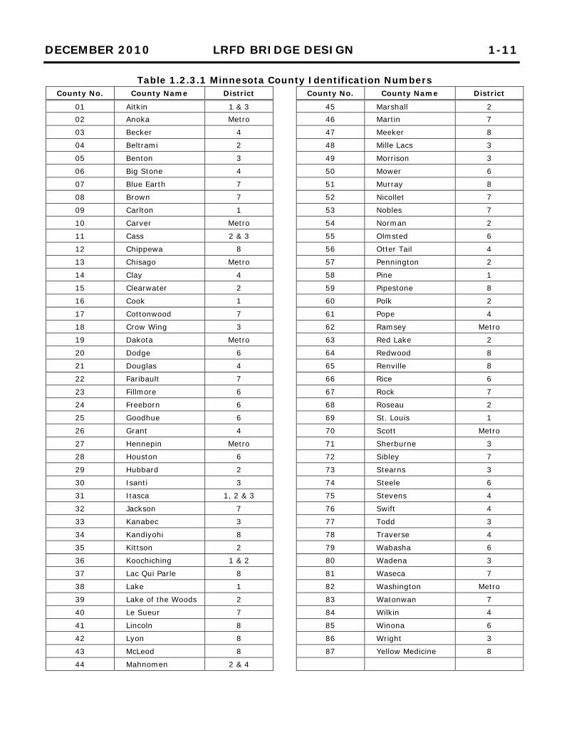
All bridge numbers are assigned by the Bridge Office. A complete listing of all numbered bridges is available in computer printout form entitled “Minnesota Trunk Highway Bridge Log- Statewide Listing”. See Table 1.2.3.1 for a listing of the county identification numbers.
DECEMBER 2010 LRFD BRIDGE DESIGN 1-11
Table 1.2.3.1 Minnesota County Identification Numbers County No. County Name District County No. County Name District
01 Aitkin 1 & 3 45 Marshall 2 02 Anoka Metro 46 Martin 7
03 Becker 4 47 Meeker 8
04 Beltrami 2 48 Mille Lacs 3
05 Benton 3 49 Morrison 3
06 Big Stone 4 50 Mower 6
07 Blue Earth 7 51 Murray 8
08 Brown 7 52 Nicollet 7
09 Carlton 1 53 Nobles 7
10 Carver Metro 54 Norman 2
11 Cass 2 & 3 55 Olmsted 6
12 Chippewa 8 56 Otter Tail 4
13 Chisago Metro 57 Pennington 2
14 Clay 4 58 Pine 1
15 Clearwater 2 59 Pipestone 8
16 Cook 1 60 Polk 2
17 Cottonwood 7 61 Pope 4
18 Crow Wing 3 62 Ramsey Metro
19 Dakota Metro 63 Red Lake 2
20 Dodge 6 64 Redwood 8
21 Douglas 4 65 Renville 8
22 Faribault 7 66 Rice 6
23 Fillmore 6 67 Rock 7
24 Freeborn 6 68 Roseau 2
25 Goodhue 6 69 St. Louis 1
26 Grant 4 70 Scott Metro
27 Hennepin Metro 71 Sherburne 3
28 Houston 6 72 Sibley 7
29 Hubbard 2 73 Stearns 3
30 Isanti 3 74 Steele 6
31 Itasca 1, 2 & 3 75 Stevens 4
32 Jackson 7 76 Swift 4
33 Kanabec 3 77 Todd 3
34 Kandiyohi 8 78 Traverse 4
35 Kittson 2 79 Wabasha 6
36 Koochiching 1 & 2 80 Wadena 3
37 Lac Qui Parle 8 81 Waseca 7
38 Lake 1 82 Washington Metro
39 Lake of the Woods 2 83 Watonwan 7
40 Le Sueur 7 84 Wilkin 4
41 Lincoln 8 85 Winona 6
42 Lyon 8 86 Wright 3
43 McLeod 8 87 Yellow Medicine 8
44 Mahnomen 2 & 4
DECEMBER 2010 LRFD BRIDGE DESIGN 1-12
Bridge designs shall typically consider Strength, Service, Extreme Event, and Fatigue limit states. The limit state checks will vary with the component under consideration. Not all elements will require consideration of all limit states. For example, the fatigue limit state need not be considered for concrete deck slabs in multigirder applications. This section covers the Bridge Office procedures for checking of bridge plans, scheduling of projects, and revising or creating standards. The general practice of most engineering offices is to require that designs they produce be checked before they are reviewed and certified by the “Engineer in Responsible Charge”. Although this practice has always been required for structures designed for Mn/DOT, it is recognized that the quality of the checking process often varies according to time restraints, confidence in the designer, and the instructions given to the checker. Therefore, in order to maintain a consistent design checking process the following guidance is given for routine bridge designs. For more complex or unusual designs, the checker is advised to discuss additional requirements with the design unit leader. Also, the checking process described is not meant to apply to the check or review functions required for Mn/DOT review of consultant plans (see Section 1.3.2.) or for construction false work reviews. (See the Bridge Construction Manual.) Three types of design checking will apply: 1) An independent analysis of the completed design. 2) A check of original design computations for mathematical accuracy,
application of code, and accepted engineering practice. 3) A review of drafted details for constructibility and accepted
engineering practice. Generally, an independent analysis to confirm the adequacy of the complete design is preferred. Significant differences should be discussed and resolved before the plan is certified. The separate set of calculations should be included with the design file as a record of the completed design check. When circumstances prevent a complete independent analysis, as a minimum, an independent analysis shall be completed for the following: 1) Live and dead loads 2) Controlling beam lines 3) A pier cap
1.3 Procedures
1.3.1 Checking of Mn/DOT Prepared Bridge Plans
1.2.4 Limit States to Consider in Design
DECEMBER 2010 LRFD BRIDGE DESIGN 1-13
4) A pier footing 5) Main reinforcement for high abutments 6) An abutment footing However, for the elements not independently analyzed, the original computations should be checked for mathematical accuracy of original design computations, applications of code, and accepted engineering practice. Checked computations should be initialed by the checker, and the independent analysis should be included in the design file. When doing a separate analysis, the checker may make simplifying assumptions to streamline the checking process. However, when major differences are found, results must be discussed and resolved with the designer. For instance, for normal piers, piling might be analyzed for dead and live loads only if lateral loads appear to have been reasonably applied in the original computations or the “AISC Beam Diagram and Formula Tables” may be used to approximate pier cap moment and shear. Whether the check is a completely independent analysis or a minimal analysis combined with a computations check, some details, such as the reinforcing details in a wall corner, also require review by the checker. Often referencing old bridge plans with similar details allows the checker to compare the current design to details that have performed well in the past. Consultant prepared bridge plans are created by private engineering firms through contracts with the Department or other government agencies. The finished plans are complete to the extent that they can be used for construction. The Engineer of Record is responsible for the completeness and accuracy of the work. Final design calculations and plan sheets must be completely checked and reconciled prior to submittal. Review comments from the State do not relieve the Engineer of Record of the responsibility for an accurate and complete bridge plan. Since these plans receive the signature of the State Bridge Engineer, there must be assurance that the plans are geometrically accurate and buildable; structural design is adequate and design codes have been correctly applied; proper direction is given to the construction contractor; and all construction costs are accounted for. Plan errors may cause costly construction delays or safety may be compromised by an inadequate design.
1.3.2 Checking of Consultant Prepared Bridge Plans
DECEMBER 2010 LRFD BRIDGE DESIGN 1-14
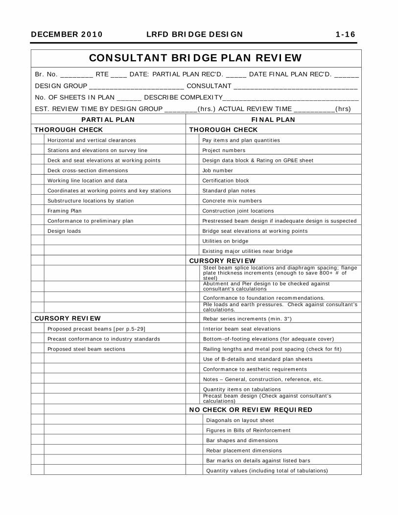
To keep consultant plan reviews consistent and timely, a procedure was developed as a guide that assigns priority to specific items in the plans. The overall review includes “a Thorough Check” and “Cursory Review” of various items. The distinction between “Thorough Check” and “Cursory Review” is as follows: Thorough Check refers to performing complete mathematical computations in order to identify discrepancies in the plans, or conducting careful comparisons of known data and standards of the Project with values given in the plan. Cursory Review refers to a comparative analysis for agreement with standard practice and consistency with similar structures, all with application of engineering judgment. Mathematical analysis is not required, but may be deemed necessary to identify the extent of a discrepancy. The review procedure is listed on the CONSULTANT BRIDGE PLAN REVIEW form following this section. Headings on this list are defined as follows: PARTIAL PLAN: In order to assure that the consultant is proceeding in the right direction, an early submittal of the plan is required. This submittal usually consists of the General Plan and Elevation sheet showing the overall geometry of the structure and the proposed beam type and spacing; the Bridge Layout Sheet; the Framing Plan sheet; and the Bridge Survey sheets. Errors and inconsistencies found in this phase can be corrected before the entire plan is completed. For example, a framing plan, including the proposed beams, must be assured as workable on the partial plan before the consultant gets deep into the design of the remainder of the bridge. FINAL PLAN: A final plan should be complete in all areas to the extent that it can be certified by the designer, although a certification signature is not required for this phase. THOROUGH CHECK: Items indicated for checking on the consultant’s partial plan must be correct. Given geometry must fit the roadway layout. Most of this information can be checked using data from the approved preliminary plan. Approval of the partial plan will indicate that Mn/DOT is satisfied with the geometry and proposed structure, and the consultant may proceed with further development of the plan. For the final plan, obvious drafting and numerical errors should be marked to
DECEMBER 2010 LRFD BRIDGE DESIGN 1-15
point out the errors to the consultant; however, the reviewer should not provide corrections to errors in the consultant’s numerical computations. Checking on the final plan should be thorough to eliminate possible errors that may occur, such as the pay items in the Schedule of Quantities. Plan notes and pay items can be difficult for a consultant to anticipate because of frequent changes by Mn/DOT. Pay items must be correct because these are carried throughout the entire accounting system for the Project. Plan (P) quantities must also be correctly indicated. CURSORY REVIEW: Normally, a cursory review would not require numerical calculations. This type of review can be conducted by reading and observing the contents of the plan in order to assure the completeness of the work. The reviewer should be observant to recognize what looks right and what doesn’t look right. Obvious errors or inconsistencies on any parts of the plan should be marked for correction. Although structural design is usually the major focus of any plan, most consultants are well versed in design procedures and should need only minimal assistance from the Bridge Office. A comparison of the consultant’s calculations with the plan details should be performed to assure that the plans reflect their design and that the applicable codes are followed. An independent design by the Bridge Office is time consuming and is not recommended unless there is a reasonable doubt as to the adequacy of the consultant’s design. NO REVIEW: A thorough review of these items would be time-consuming and may not produce corrections that are vital to construction; therefore, it is recommended that little or no time be spent on the listed items. Numerous errors can occur in the Bills of Reinforcement and quantity values. However, checking this information is also time-consuming, hence the burden of providing correct data should be placed on the consultant.
DECEMBER 2010 LRFD BRIDGE DESIGN 1-16
CONSULTANT BRIDGE PLAN REVIEW Br. No. ________ RTE ____ DATE: PARTIAL PLAN REC'D. _____ DATE FINAL PLAN REC'D. ______
DESIGN GROUP _______________________ CONSULTANT ______________________________
No. OF SHEETS IN PLAN ______ DESCRIBE COMPLEXITY_________________________________
EST. REVIEW TIME BY DESIGN GROUP ________(hrs.) ACTUAL REVIEW TIME __________(hrs)
PARTIAL PLAN FINAL PLAN THOROUGH CHECK THOROUGH CHECK Horizontal and vertical clearances Pay items and plan quantities
Stations and elevations on survey line Project numbers
Deck and seat elevations at working points Design data block & Rating on GP&E sheet
Deck cross-section dimensions Job number
Working line location and data Certification block
Coordinates at working points and key stations Standard plan notes
Substructure locations by station Concrete mix numbers
Framing Plan Construction joint locations
Conformance to preliminary plan Prestressed beam design if inadequate design is suspected
Design loads Bridge seat elevations at working points
Utilities on bridge
Existing major utilities near bridge
CURSORY REVIEW Steel beam splice locations and diaphragm spacing; flange
plate thickness increments (enough to save 800+ # of steel)
Abutment and Pier design to be checked against consultant’s calculations
Conformance to foundation recommendations.
Pile loads and earth pressures. Check against consultant’s calculations.
CURSORY REVIEW Rebar series increments (min. 3")
Proposed precast beams [per p.5-29] Interior beam seat elevations
Precast conformance to industry standards Bottom-of-footing elevations (for adequate cover)
Proposed steel beam sections Railing lengths and metal post spacing (check for fit)
Use of B-details and standard plan sheets
Conformance to aesthetic requirements
Notes – General, construction, reference, etc.
Quantity items on tabulations
Precast beam design (Check against consultant’s calculations)
NO CHECK OR REVIEW REQUIRED Diagonals on layout sheet
Figures in Bills of Reinforcement
Bar shapes and dimensions
Rebar placement dimensions
Bar marks on details against listed bars
Quantity values (including total of tabulations)
DECEMBER 2010 LRFD BRIDGE DESIGN 1-17
Major bridges are generally defined as bridges containing spans 250 feet and greater in length. A major or specialty bridge may be determined by its type of design, including overall size (length, width, span length, or number and configuration of spans), cost, complexity, feature crossed, security concerns, pier size or shape, or unusual site or foundation conditions. Additionally, the Bridge Design Engineer may elect to require a peer review for unique bridge types. The bridge type will be evaluated by the Preliminary Plans Engineer and the Bridge Design Engineer to determine if it should be considered a major or specialty bridge. Upon concurrence with the State Bridge Engineer, a notation of “Major Bridge” or “Specialty Bridge” will be indicated on the approved preliminary plan. For major bridges designed by consultants, Mn/DOT will require an independent peer review of the design by a second design firm. Peer review requirements will be described in the Request for Proposal for consultants. An exception to this requirement is steel plate girder bridges, where review will continue to be performed by in-house design units. See the Bridge Design Engineer for consultation on these requirements. Once the determination has been made that a particular bridge falls into the category of “Major Bridge” or “Specialty Bridge,” an independent design review will be required as part of the original design. This design review may be performed by either in-house Bridge Office staff qualified to review the particular type of design, or by a consultant. Specific design elements for review will be detailed in each contract. The Engineer of Record is responsible for the completeness and accuracy of the work. Final design calculations and plan sheets must be completely checked and reconciled prior to submittal. Review comments from the State or Peer Reviewer does not relieve the Engineer of Record of the responsibility for an accurate and complete bridge plan. The Engineer of Record will cooperate with the Peer Reviewer as part of the project team. The Peer Reviewer will participate as part of the project team from the beginning of design to understand the assumptions and develop a relationship with the Engineer of Record. The following stages of design will be reviewed by the Peer Reviewer for concurrence:
1.3.3 Peer Review for Major or Specialty Bridges
DECEMBER 2010 LRFD BRIDGE DESIGN 1-18
Design and Load Rating Criteria: Design specifications, construction specifications, design loads and load combinations, construction loads for design, materials and allowable stresses, foundation type, factored pile resistance and resistance factors, and permit trucks.
Concept Design: Bridge geometrics, typical sections and dimensions, component sizes, framing plan, location and type of expansion joints, location and type of bearings, computer models for girder design, construction staging, construction sequence, river foundation report, vessel impact study, and outline of special provisions.
Superstructure Final Design: Independent calculations and design; method of analysis (line girder or three dimensional); modeling assumptions; composite and non-composite section properties, member capacities, dead load and live load moments, shears, and stresses at 1/10th points along girder lines, all primary connections and other points of interest; dead and live load deflections; deck design; deck stresses; and deck pour sequence.
Substructure Final Design: Independent calculations and design, assumptions, points of fixity, cofferdam design, and pier design and details.
Constructability: Shipping limitations, erection sequence and stability issues, crane sizes and boom lengths, construction overhead clearances, interference/restrictions on construction due to site conditions, shoring tower locations, falsework review.
Plan: adequacy of construction plans and specifications provided to contractor.
Load Rating: Independent load rating analysis, rating for moment and shear at 1/10th points and any other points of interest of each span.
For each of the stages of design listed above, the Peer Reviewer will submit a Summary of Review Comments, which will be kept by the Peer Reviewer and will verify that the design is feasible and adequately incorporates the Design and Load Rating criteria and Concept Design parameters. The Peer Reviewer may recommend modifications that improve cost-effectiveness or constructability of the design along with Summaries of Review Comments for Design and Load Rating criteria and Concept Design.
The Peer Reviewer will perform reviews at the 30% (Concept Design), 60% (Final Design), and 95% (Plan/Constructability and Load Rating) completion stages using independent design computations as required.

DECEMBER 2010 LRFD BRIDGE DESIGN 1-19
The Peer Reviewer will conduct the final design review without the aid of the original design calculations. The Peer Reviewer will use structural design/analysis software different than that used in the original design—when available—by the Engineer of Record. This will result in a separate set of design calculations—performed by the Peer Reviewer—that will be documented in a report that will be certified. The report will then be compared to the original design performed by the Engineer of Record. The Peer Reviewer will note any changes or recommendations and provide the results to Mn/DOT for review.
The results of the peer review will determine that the design and plans are in compliance with design standards and the established design criteria. The Bridge Design Engineer will resolve issues with the Engineer of Record and Peer Reviewer.
DECEMBER 2010 LRFD BRIDGE DESIGN 1-20
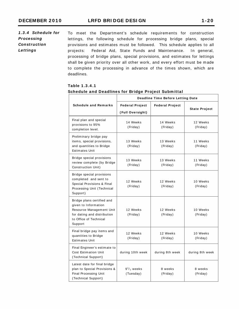
To meet the Department’s schedule requirements for construction lettings, the following schedule for processing bridge plans, special provisions and estimates must be followed. This schedule applies to all projects: Federal Aid, State Funds and Maintenance. In general, processing of bridge plans, special provisions, and estimates for lettings shall be given priority over all other work, and every effort must be made to complete the processing in advance of the times shown, which are deadlines. Table 1.3.4.1 Schedule and Deadlines for Bridge Project Submittal
Schedule and Remarks
Deadline Time Before Letting Date
Federal Project
(Full Oversight)
Federal Project State Project
Final plan and special provisions to 95% completion level.
14 Weeks (Friday)
14 Weeks (Friday)
12 Weeks (Friday)
Preliminary bridge pay items, special provisions, and quantities to Bridge Estimates Unit
13 Weeks (Friday)
13 Weeks (Friday)
11 Weeks (Friday)
Bridge special provisions review complete (by Bridge Construction Unit)
13 Weeks (Friday)
13 Weeks (Friday)
11 Weeks (Friday)
Bridge special provisions completed and sent to Special Provisions & Final Processing Unit (Technical Support)
12 Weeks (Friday)
12 Weeks (Friday)
10 Weeks (Friday)
Bridge plans certified and given to Information Resource Management Unit for dating and distribution to Office of Technical Support
12 Weeks (Friday)
12 Weeks (Friday)
10 Weeks (Friday)
Final bridge pay items and quantities to Bridge Estimates Unit
12 Weeks (Friday)
12 Weeks (Friday)
10 Weeks (Friday)
Final Engineer’s estimate to Cost Estimation Unit (Technical Support)
during 10th week during 8th week during 8th week
Latest date for final bridge plan to Special Provisions & Final Processing Unit (Technical Support)
91/2 weeks (Tuesday)
8 weeks (Friday)
8 weeks (Friday)
1.3.4 Schedule for Processing Construction Lettings
DECEMBER 2010 LRFD BRIDGE DESIGN 1-21
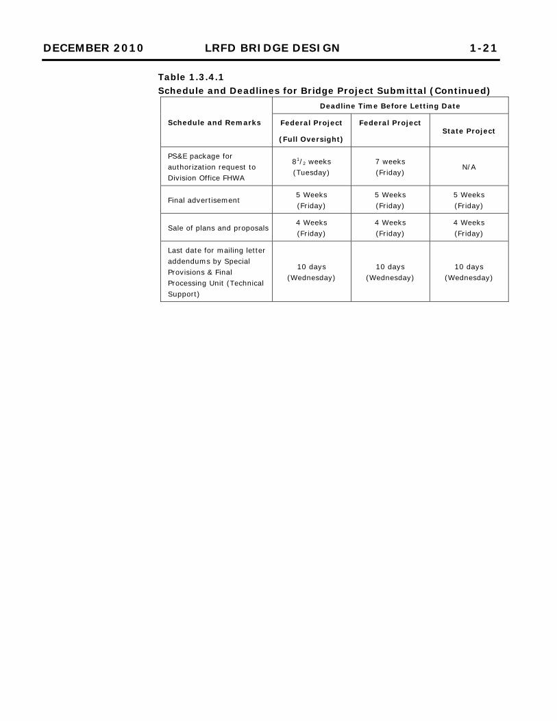
Table 1.3.4.1 Schedule and Deadlines for Bridge Project Submittal (Continued)
Schedule and Remarks
Deadline Time Before Letting Date
Federal Project
(Full Oversight)
Federal Project State Project
PS&E package for authorization request to Division Office FHWA
81/2 weeks (Tuesday)
7 weeks (Friday)
N/A
Final advertisement 5 Weeks (Friday)
5 Weeks (Friday)
5 Weeks (Friday)
Sale of plans and proposals 4 Weeks (Friday)
4 Weeks (Friday)
4 Weeks (Friday)
Last date for mailing letter addendums by Special Provisions & Final Processing Unit (Technical Support)
10 days (Wednesday)
10 days (Wednesday)
10 days (Wednesday)
DECEMBER 2010 LRFD BRIDGE DESIGN 1-22
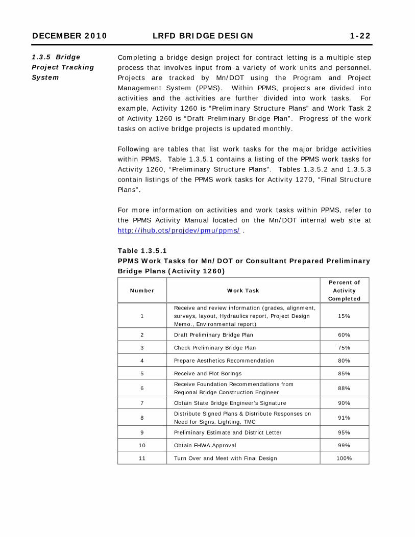
Completing a bridge design project for contract letting is a multiple step process that involves input from a variety of work units and personnel. Projects are tracked by Mn/DOT using the Program and Project Management System (PPMS). Within PPMS, projects are divided into activities and the activities are further divided into work tasks. For example, Activity 1260 is “Preliminary Structure Plans” and Work Task 2 of Activity 1260 is “Draft Preliminary Bridge Plan”. Progress of the work tasks on active bridge projects is updated monthly. Following are tables that list work tasks for the major bridge activities within PPMS. Table 1.3.5.1 contains a listing of the PPMS work tasks for Activity 1260, “Preliminary Structure Plans”. Tables 1.3.5.2 and 1.3.5.3 contain listings of the PPMS work tasks for Activity 1270, “Final Structure Plans”. For more information on activities and work tasks within PPMS, refer to the PPMS Activity Manual located on the Mn/DOT internal web site at http://ihub.ots/projdev/pmu/ppms/ . Table 1.3.5.1 PPMS Work Tasks for Mn/DOT or Consultant Prepared Preliminary Bridge Plans (Activity 1260)
Number Work Task Percent of
Activity Completed
1 Receive and review information (grades, alignment, surveys, layout, Hydraulics report, Project Design Memo., Environmental report)
15%
2 Draft Preliminary Bridge Plan 60%
3 Check Preliminary Bridge Plan 75%
4 Prepare Aesthetics Recommendation 80%
5 Receive and Plot Borings 85%
6 Receive Foundation Recommendations from Regional Bridge Construction Engineer
88%
7 Obtain State Bridge Engineer’s Signature 90%
8 Distribute Signed Plans & Distribute Responses on Need for Signs, Lighting, TMC
91%
9 Preliminary Estimate and District Letter 95%
10 Obtain FHWA Approval 99%
11 Turn Over and Meet with Final Design 100%
1.3.5 Bridge Project Tracking System
DECEMBER 2010 LRFD BRIDGE DESIGN 1-23
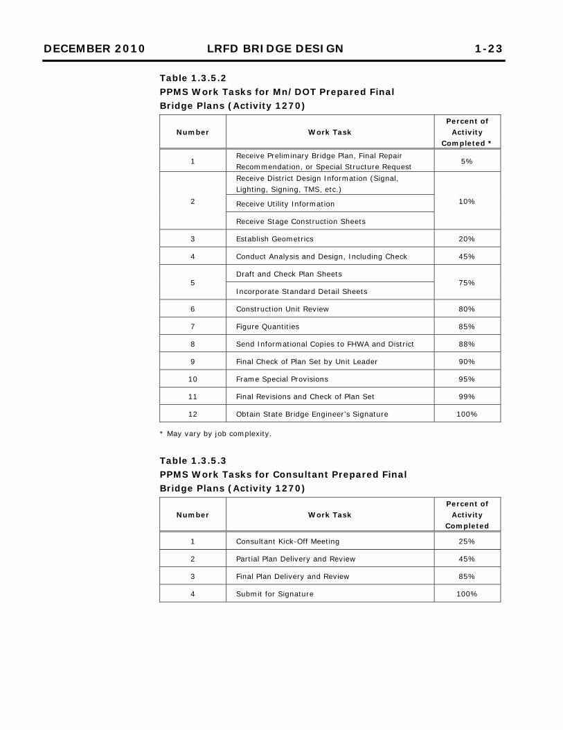
Table 1.3.5.2 PPMS Work Tasks for Mn/DOT Prepared Final Bridge Plans (Activity 1270)
Number Work Task Percent of
Activity Completed *
1 Receive Preliminary Bridge Plan, Final Repair Recommendation, or Special Structure Request
5%
2
Receive District Design Information (Signal, Lighting, Signing, TMS, etc.)
10% Receive Utility Information
Receive Stage Construction Sheets
3 Establish Geometrics 20%
4 Conduct Analysis and Design, Including Check 45%
5 Draft and Check Plan Sheets
75% Incorporate Standard Detail Sheets
6 Construction Unit Review 80%
7 Figure Quantities 85%
8 Send Informational Copies to FHWA and District 88%
9 Final Check of Plan Set by Unit Leader 90%
10 Frame Special Provisions 95%
11 Final Revisions and Check of Plan Set 99%
12 Obtain State Bridge Engineer’s Signature 100%
* May vary by job complexity. Table 1.3.5.3 PPMS Work Tasks for Consultant Prepared Final Bridge Plans (Activity 1270)
Number Work Task Percent of
Activity Completed
1 Consultant Kick-Off Meeting 25%
2 Partial Plan Delivery and Review 45%
3 Final Plan Delivery and Review 85%
4 Submit for Signature 100%
DECEMBER 2010 LRFD BRIDGE DESIGN 1-24
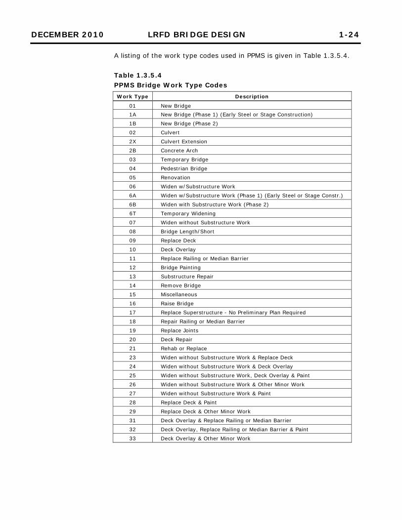
A listing of the work type codes used in PPMS is given in Table 1.3.5.4. Table 1.3.5.4 PPMS Bridge Work Type Codes Work Type Description
01 New Bridge 1A New Bridge (Phase 1) (Early Steel or Stage Construction)
1B New Bridge (Phase 2)
02 Culvert
2X Culvert Extension
2B Concrete Arch
03 Temporary Bridge
04 Pedestrian Bridge
05 Renovation
06 Widen w/Substructure Work
6A Widen w/Substructure Work (Phase 1) (Early Steel or Stage Constr.)
6B Widen with Substructure Work (Phase 2)
6T Temporary Widening
07 Widen without Substructure Work
08 Bridge Length/Short
09 Replace Deck
10 Deck Overlay
11 Replace Railing or Median Barrier
12 Bridge Painting
13 Substructure Repair
14 Remove Bridge
15 Miscellaneous
16 Raise Bridge
17 Replace Superstructure - No Preliminary Plan Required
18 Repair Railing or Median Barrier
19 Replace Joints
20 Deck Repair
21 Rehab or Replace
23 Widen without Substructure Work & Replace Deck
24 Widen without Substructure Work & Deck Overlay
25 Widen without Substructure Work, Deck Overlay & Paint
26 Widen without Substructure Work & Other Minor Work
27 Widen without Substructure Work & Paint
28 Replace Deck & Paint
29 Replace Deck & Other Minor Work
31 Deck Overlay & Replace Railing or Median Barrier
32 Deck Overlay, Replace Railing or Median Barrier & Paint
33 Deck Overlay & Other Minor Work
DECEMBER 2010 LRFD BRIDGE DESIGN 1-25
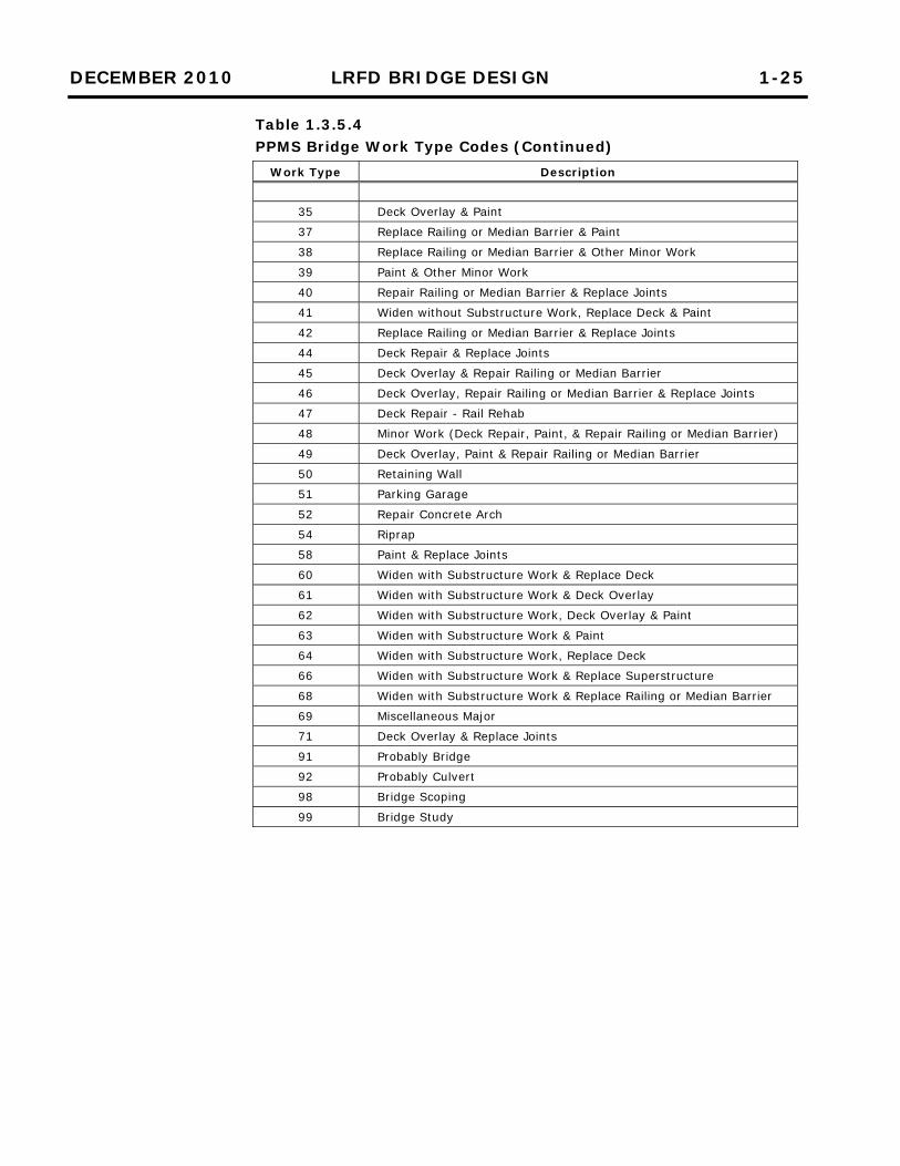
Table 1.3.5.4 PPMS Bridge Work Type Codes (Continued)
Work Type Description
35 Deck Overlay & Paint
37 Replace Railing or Median Barrier & Paint
38 Replace Railing or Median Barrier & Other Minor Work
39 Paint & Other Minor Work
40 Repair Railing or Median Barrier & Replace Joints
41 Widen without Substructure Work, Replace Deck & Paint
42 Replace Railing or Median Barrier & Replace Joints
44 Deck Repair & Replace Joints
45 Deck Overlay & Repair Railing or Median Barrier
46 Deck Overlay, Repair Railing or Median Barrier & Replace Joints
47 Deck Repair - Rail Rehab
48 Minor Work (Deck Repair, Paint, & Repair Railing or Median Barrier)
49 Deck Overlay, Paint & Repair Railing or Median Barrier
50 Retaining Wall
51 Parking Garage
52 Repair Concrete Arch
54 Riprap
58 Paint & Replace Joints
60 Widen with Substructure Work & Replace Deck
61 Widen with Substructure Work & Deck Overlay
62 Widen with Substructure Work, Deck Overlay & Paint
63 Widen with Substructure Work & Paint
64 Widen with Substructure Work, Replace Deck
66 Widen with Substructure Work & Replace Superstructure
68 Widen with Substructure Work & Replace Railing or Median Barrier
69 Miscellaneous Major
71 Deck Overlay & Replace Joints
91 Probably Bridge
92 Probably Culvert
98 Bridge Scoping
99 Bridge Study
DECEMBER 2010 LRFD BRIDGE DESIGN 1-26
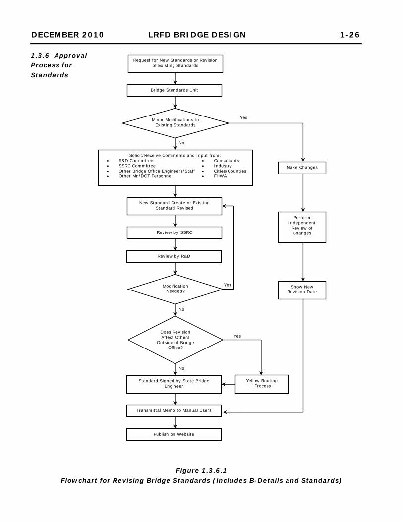
1.3.6 Approval Process for Standards
Figure 1.3.6.1 Flowchart for Revising Bridge Standards (includes B-Details and Standards)
Request for New Standards or Revision of Existing Standards
Minor Modifications to Existing Standards
Solicit/Receive Comments and Input from: R&D Committee SSRC Committee Other Bridge Office Engineers/Staff Other Mn/DOT Personnel
Consultants Industry Cities/Counties FHWA
New Standard Create or Existing Standard Revised
Yellow Routing Process
Make Changes
Perform Independent
Review of Changes
Show New Revision Date
Review by SSRC
Standard Signed by State Bridge Engineer
Transmittal Memo to Manual Users
Publish on Website
Modification Needed?
Review by R&D
Does Revision Affect Others
Outside of Bridge Office?
Yes
Yes
Yes
No
No
No
Bridge Standards Unit