low voltage varplus logic vl series - schneider electric · 2 e2-35-1 varplus logic l series ser...
TRANSCRIPT

VarPlus Logic VL series
Low Voltage
User manual
PF Correction Controller

VarPlus Logic VL6 / VL12 PFC controller: to download the user manual or other documentation visit www.schneider-electric.com. Type de device model (for e.g. VarPlus Logic VL12) in the search field.
1
FR
7EN02-0375-01_TDM
VarPlus Logic VL series User manual
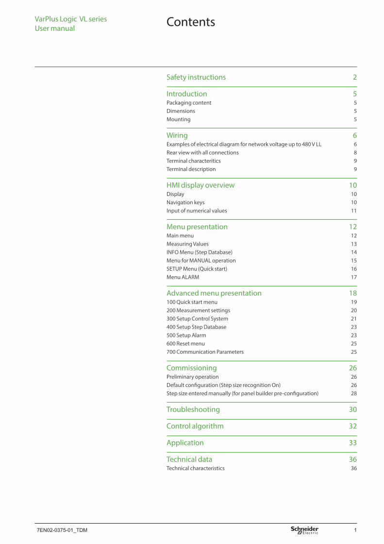
Contents
Safety instructions 2
Introduction 5Packaging content 5Dimensions 5Mounting 5
Wiring 6Examples of electrical diagram for network voltage up to 480 V LL 6Rear view with all connections 8Terminal characteritics 9Terminal description 9
HMI display overview 10Display 10Navigation keys 10Input of numerical values 11
Menu presentation 12Main menu 12Measuring Values 13INFO Menu (Step Database) 14Menu for MANUAL operation 15SETUP Menu (Quick start) 16Menu ALARM 17
Advanced menu presentation 18100 Quick start menu 19200 Measurement settings 20300 Setup Control System 21400 Setup Step Database 23500 Setup Alarm 23600 Reset menu 25700 Communication Parameters 25
Commissioning 26Preliminary operation 26Default configuration (Step size recognition On) 26Step size entered manually (for panel builder pre-configuration) 28
Troubleshooting 30
Control algorithm 32
Application 33
Technical data 36Technical characteristics 36

2 7EN02-0375-01
VarPlus Logic VL series User manual
Safety instructions
Important informationRead these instructions carefully and look at the equipment to become familiar with the device before trying to install, operate, service or maintain it. The following special messages may appear throughout this bulletin or on the equipment to warn of potential hazards or to call attention to information that clarifies or simplifies a procedure.
The addition of either symbol to a “Danger” or “Warning” safety label indicates that an electrical hazard exists which will result in personal injury if the instructions are not followed.
This is the safety alert symbol. It is used to alert you to potential personal injury hazards. Obey all safety messages that follow this symbol to avoid possible injury or death.
DANGERDANGER indicates a hazardous situation which, if not avoided, will result in death or serious injury.
WARNINGWARNING indicates a hazardous situation which, if not avoided, could result in death or serious injury.
CAUTIONCAUTION indicates a hazardous situation which, if not avoided, could result in minor or moderate injury.
NOTICENOTICE is used to address practices not related to physical injury.
NOTE: Provides additional information to clarify or simply a procedure.
Please noteElectrical equipment should be installed, operated, serviced and maintained only by qualified personnel. No responsibility is assumed by Schneider Electric for any consequences arising out of the use of this material.A qualified person is one who has skills and knowledge related to the construction, installation, and operation of electrical equipment and has received safety training to recognize and avoid the hazards involved.
Legal informationThe Schneider Electric brand and any registered trademarks of Schneider Electric Industries SAS referred to in this guide are the sole property of Schneider Electric SA and its subsidiaries. They may not be used for any purpose without the owner's permission, given in writing. This guide and its content are protected, within the meaning of the French intellectual property code (Code de la propriété intellectuelle français, referred to hereafter as "the Code"), under the laws of copyright coveringtexts, drawings and models, as well as by trademark law. You agree not to reproduce, other than for your own personal, noncommercial use as defined in the Code, all or part of this guide on any medium whatsoever without Schneider Electric’s permission, given in writing. You also agree not to establish any hypertext links to this guide or its content.Schneider Electric does not grant any right or license for the personal andnoncommercial use of the guide or its content, except for a non-exclusive license to consult it on an "as is" basis, at your own risk. All other rights are reserved.
Electrical equipment should be installed, operated, serviced and main-tained only by qualified personnel. No responsibility is assumed by Schneider Electric for any consequences arising out of the use of this material.
As standards, specifications and designs change from time to time, please ask for confirmation of the information given in this publication.

37EN02-0375-01
VarPlus Logic VL series User manual
Legal informationThe Schneider Electric brand and any registered trademarks of Schneider Electric Industries SAS referred to in this guide are the sole property of Schneider Electric SA and its subsidiaries. They may not be used for any purpose without the owner's permission, given in writing. This guide and its content are protected, within the meaning of the French intellectual property code (Code de la propriété intellectuelle français, referred to hereafter as "the Code"), under the laws of copyright coveringtexts, drawings and models, as well as by trademark law. You agree not to reproduce, other than for your own personal, noncommercial use as defined in the Code, all or part of this guide on any medium whatsoever without Schneider Electric’s permission, given in writing. You also agree not to establish any hypertext links to this guide or its content.Schneider Electric does not grant any right or license for the personal andnoncommercial use of the guide or its content, except for a non-exclusive license to consult it on an "as is" basis, at your own risk. All other rights are reserved.
Electrical equipment should be installed, operated, serviced and main-tained only by qualified personnel. No responsibility is assumed by Schneider Electric for any consequences arising out of the use of this material.
As standards, specifications and designs change from time to time, please ask for confirmation of the information given in this publication.

4 7EN02-0375-01
VarPlus Logic VL series User manual
Safety instructions
Before you begin• This manual cannot be used to define or determine the suitability
or reliability of these products for specific user applications. It is the duty of any such user or integrator to perform the appropriate and complete risk analysis, evaluation and testing of the products with respect to the relevant specific application or use thereof.
• When devices are used for applications with technical safety requirements, the relevant instructions must be followed.
DANGERHAZARD OF ELECTRICAL SHOCK, EXPLOSION OR ARC FLASH
• Apply appropriate personal protective equipment (PPE) and follow safe electrical work practices. See NFPA 70E in the USA, CSA Z462 or applicable local standards.
• This equipment must only be installed and serviced by qualified electrical personnel.
• Do not exceed the device’s ratings for maximum limits.• Turn off all power supplying this equipment before working on or
inside equipment.• After removing power, wait 10 minutes to allow the capacitors to
discharge before opening the doors or removing the covers. • Always use a properly rated voltage sensing device to confirm
power is off.• Carefully inspect the interior for tools left behind before closing and
sealing the door. • Replace all devices, doors and covers before turning on power to
this equipment.• Do not modify the mechanical or electrical parts.• For installation with network nominal voltage higher than 480 V
LL, add a step down transformer on voltage measurement input to comply with the PFC controller max. voltage.
Failure to follow these instructions will result in death or serious injury.
• The equipment is factory-assembled and does not require any action during the installation except those indicated below.
57EN02-0375-01
VarPlus Logic VL series User manual
Introduction
Packaging content
Dimensions
Mounting
Instruction sheet
Varplus LogicVL serie
04624
VL12
ESC
OK
VarPlus Logic
VarPlus Logic
VL12
ESC OK
1445.66
1445.66
592.32
983.85
471.85
120.47
1375.39
1375.39
1
2
2 3
3
1385.43
1385.43
CLICK
CLICK
1 – 30.03 – 0.11
mmin.
mmin.

6 7EN02-0375-01
VarPlus Logic VL series User manual
Wiring
Examples of electrical diagram
U1
F1
1
I1I2
F2
12
5
234
6789
1011
C
AL1AL2
0V
D0-D1+
TTL
U2S1S2
PE
90V - 550V
15mA - 6A
N
L1L2L3
PE
S2S1
A
B
≤ 250 VAC ≤ 480 VAC
C
D
Auxiliary (Control) TransformerE E
K1K2
K12
K1 K2 …
…
Phase-to-Neutral direct connect without VTs (3PH4W)
U1
F1
1
I1I2
F2
12
5
234
6789
1011
C
AL1AL2
0V
D0-D1+
TTL
U2S1S2
PE
90V - 550V
15mA - 6A
N
L1L2L3
PE
S2S1
D
C
A
BC
≤ 250 VAC ≤ 480 VACAuxiliary (Control) Transformer
E E
K1K2
K12
K1 K2 …
…
Phase-to-Neutral with VTs (3PH4W)

77EN02-0375-01
VarPlus Logic VL series User manual
Wiring
Examples of electrical diagram
U1
F1
1
I1I2
F2
12
5
234
6789
1011
C
AL1AL2
0V
D0-D1+
TTL
U2S1S2
PE
90V - 550V
15mA - 6A
L1L2L3
PE
S2S1
C
A
B
≤ 250 VAC ≤ 480 VAC
C
D
Auxiliary (Control) TransformerE E
K1K2
K12
K1 K2 …
…
Phase-to-Phase direct connect without VTs (3PH3W)
U1
F1
1
I1I2
F2
12
5
234
6789
1011
C
AL1AL2
0V
D0-D1+
TTL
U2S1S2
PE
90V - 550V
15mA - 6A
L1L2L3
PE
S2S1
D
C
A
B
≤ 250 VAC
C
≤ 480 VACAuxiliary (Control) Transformer
E E
K1K2
K12
K1 K2 …
…
Phase-to-Phase with VTs (3PH3W)

8 7EN02-0375-01
VarPlus Logic VL series User manual
Note:The wiring is different if you are replacing a Varlogic NR or Varlogic NRC controller with a VarPlus Logic VL controller. The wiring diagram for retrofit of Varlogic NR or Varlogic NRC with VarPlus Logic can be downloaded from www.schneider-electric.com.
Upstream protection Voltage input: 2A certified circuit breakers or fuses
Shorting block for CT
VT primary fuses and disconnect switch
Output relays: 10 A (max.) certified circuit breakers or fuses
E Capacitor primary fuses or CB’s
Note:• Clearly label the device’s disconnect circuit mechanism and install it
within easy reach of the operator. • The fuses / circuit breakers must be rated for the installation voltage and
sized for the available fault current.• Fuses or circuit breakers for neutral terminal are required if the source
neutral connection is not grounded. • Put the VT ratio in programming menu, if the VT is present on input
voltage measurement. • Before installation, see the wiring diagram behind the product (near the
terminal), for the wiring connections.
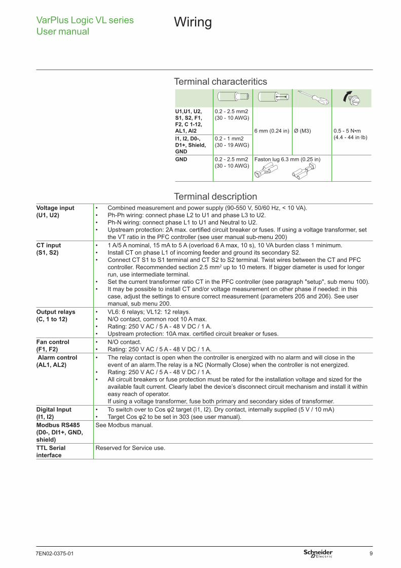
Rear view with all connections
- I1- I2
- AL1- AL2
SetupUnCtAiPFCCP1StOUt
U1 -U2 -
C 1 23456789
101112
PE
S1 -S2 -
RS485Modbus
F1F2
Wiring
97EN02-0375-01
VarPlus Logic VL series User manual
Terminal characteritics
U1,U1, U2, S1, S2, F1, F2, C 1-12, AL1, Al2
0.2 - 2.5 mm2 (30 - 10 AWG)
6 mm (0.24 in) Ø (M3) 0.5 - 5 N•m (4.4 - 44 in·lb)I1, I2, D0-,
D1+, Shield, GND
0.2 - 1 mm2 (30 - 19 AWG)
GND 0.2 - 2.5 mm2 (30 - 10 AWG)
Faston lug 6.3 mm (0.25 in)
Terminal descriptionVoltage input (U1, U2)
• Combined measurement and power supply (90-550 V, 50/60 Hz, < 10 VA). • Ph-Ph wiring: connect phase L2 to U1 and phase L3 to U2. • Ph-N wiring: connect phase L1 to U1 and Neutral to U2. • Upstream protection: 2A max. certified circuit breaker or fuses. If using a voltage transformer, set
the VT ratio in the PFC controller (see user manual sub-menu 200)CT input (S1, S2)
• 1 A/5 A nominal, 15 mA to 5 A (overload 6 A max, 10 s), 10 VA burden class 1 minimum. • Install CT on phase L1 of incoming feeder and ground its secondary S2.• Connect CT S1 to S1 terminal and CT S2 to S2 terminal. Twist wires between the CT and PFC
controller. Recommended section 2.5 mm2 up to 10 meters. If bigger diameter is used for longer run, use intermediate terminal.
• Set the current transformer ratio CT in the PFC controller (see paragraph "setup", sub menu 100).• It may be possible to install CT and/or voltage measurement on other phase if needed: in this
case, adjust the settings to ensure correct measurement (parameters 205 and 206). See user manual, sub menu 200.
Output relays (C, 1 to 12)
• VL6: 6 relays; VL12: 12 relays.• N/O contact, common root 10 A max. • Rating: 250 V AC / 5 A - 48 V DC / 1 A. • Upstream protection: 10A max. certified circuit breaker or fuses.
Fan control (F1, F2)
• N/O contact. • Rating: 250 V AC / 5 A - 48 V DC / 1 A.
Alarm control (AL1, AL2)
• The relay contact is open when the controller is energized with no alarm and will close in the event of an alarm.The relay is a NC (Normally Close) when the controller is not energized.
• Rating: 250 V AC / 5 A - 48 V DC / 1 A.• All circuit breakers or fuse protection must be rated for the installation voltage and sized for the
available fault current. Clearly label the device’s disconnect circuit mechanism and install it within easy reach of operator. If using a voltage transformer, fuse both primary and secondary sides of transformer.
Digital Input (I1, I2)
• To switch over to Cos φ2 target (I1, I2). Dry contact, internally supplied (5 V / 10 mA)• Target Cos φ2 to be set in 303 (see user manual).
Modbus RS485 (D0-, DI1+, GND, shield)
See Modbus manual.
TTL Serial interface
Reserved for Service use.
Wiring

10 7EN02-0375-01
VarPlus Logic VL series User manual
HMI display overview
Display
NTEXPORTCOSФ
THDHarPΔQSUI
INFOAUTOMANUALSETUPALARM
ickM°C%sVAWvarh
1 2 3 4 5 6 7 8 9 10 11 12 FAN
13
1
7
5
9
6
8
432
12
11
10
1 Digital display for measurement 9 Flashing indicates Alarm is activated
2 Displacement Power Factor (DPF) 10 Step Number illuminated when activated
3 Inductive or Capacitive DPF (Lagging or Leading) 11 Displayed Measurement
4 Units of measurement 12 Indicates exporting Power to Grid
5 Step information 13 Indicates Secondary DPF Target is activated
6 Indicates Automatic mode
7 Indicates Manual Operation of Steps mode
8 Indicates Set Up Menu mode
Navigation keys
ESC
1
2
3
4OK
1 • Increase Values • Select Menu Items
3 • Decrease Values • Select Menu Items
2 • Open Menu • Move Cursor Right • Settings
4 • Exit Menu • Move Cursor Left
1 + 3 Clear Alarms Log Buffer: Press ▲ and ▼ for 3 seconds to clear alarm log buffer.

117EN02-0375-01
VarPlus Logic VL series User manual
Display Parameters ExplainedNT Two target power factors can be set on the controller. When the secondary target power factor is active,
the NT light is illuminated on the display.EXPORT In conditions where the PFC unit is running in conjunction with a generator, the export light will be
illuminated if active power is being exported to the grid (i.e., leading DPF). If there is no generator in the circuit and the light is illuminated, a connection problem is likely.
INFO The info menu provides information regarding each step of the power factor correction unit. This includes the current size of the step in kVAr (only if the CT ratio is set), the remaining capacity of the step, the number of switch cycles and the operation of the step (automatic, permanently on or off, etc).
AUTO The two modes of operation for the controller are automatic or manual. In automatic mode, the controller decides which steps are necessary to achieve the target power factor dependent upon the chosen switching algorithm. The Auto light is illuminated when the controller is in this mode.
MANUAL The manual mode of operation is used when you want direct control of which steps should be on, off, etc. The manual light is illuminated when the controller is in this mode.
SETUP The setup menu has all settings that are required to configure the controller. There is an advanced menu that can only be accessed by holding the select/continue button until the 100 menu appears. In some instances, a pin code may be required to access these menus. The PIN code is 242. After entering the code, you can navigate to all of the other menus (200, 300, 400, 500, 600, 700).
ALARM • Alarm(s) in progress: Alarm light is flashing alternatively with alarm(s) code(s).• Alarm(s) log: displays the last five alarms that were logged. To view an alarm, enter into the menu
with the ► button and scroll with the ▲ and ▼ keys.• To reset the alarm log buffer, hold both ▲ and ▼ keys for 3 seconds.
Input of numerical valuesWhen the controller prompts for the input of a value, the process is the same: • A preset value is displayed with the first digit blinking.
- You can change the digit using the ▲ and ▼ keys. - Use the ► button to move to the next smaller digit. Repeat the above step to change the digit. - After the final digit is modified, press the ► key. This position sets multipliers k (kilo) or M (Mega). - To store the value, press the ► key, the new value is saved
• The value is not stored if the value is outside the allowed range. For possible ranges, see the advanced menu described in this manual.
• At any time, to return to the menu without changing the value, press the ESC ◄ escape key.
HMI display overview
12 7EN02-0375-01
VarPlus Logic VL series User manual
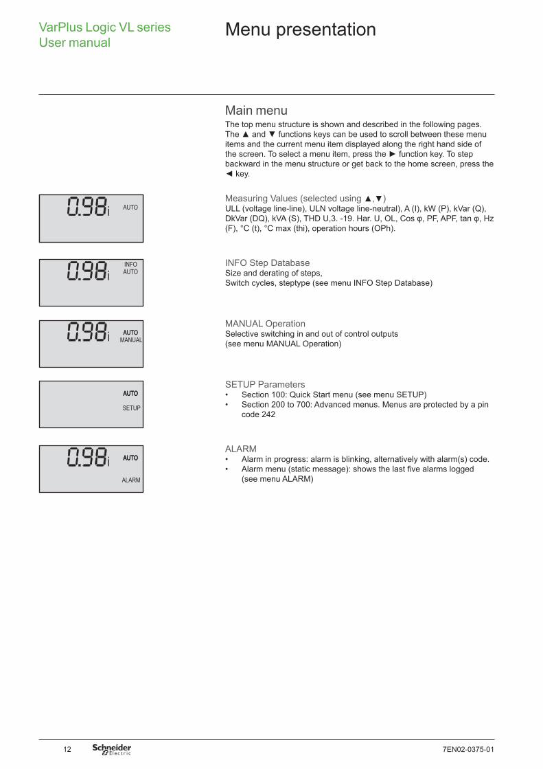
Main menuThe top menu structure is shown and described in the following pages. The ▲ and ▼ functions keys can be used to scroll between these menu items and the current menu item displayed along the right hand side of the screen. To select a menu item, press the ► function key. To step backward in the menu structure or get back to the home screen, press the ◄ key.
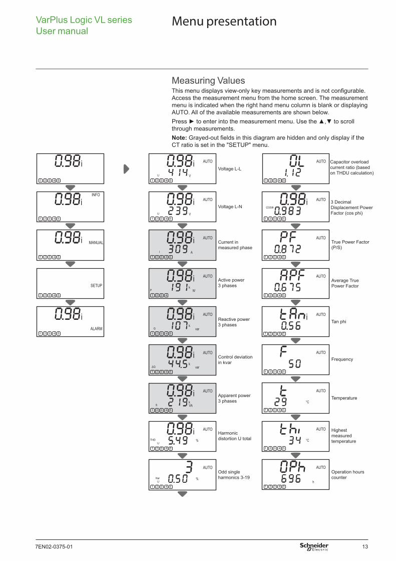
AUTOiMeasuring Values (selected using ▲,▼)ULL (voltage line-line), ULN voltage line-neutral), A (I), kW (P), kVar (Q), DkVar (DQ), kVA (S), THD U,3. -19. Har. U, OL, Cos φ, PF, APF, tan φ, Hz (F), °C (t), °C max (thi), operation hours (OPh).
INFOAUTOi
INFO Step Database Size and derating of steps,Switch cycles, steptype (see menu INFO Step Database)
AUTOMANUAL
AUTOiMANUAL Operation Selective switching in and out of control outputs (see menu MANUAL Operation)
AUTO
SETUP
AUTOAUTOSETUP Parameters• Section 100: Quick Start menu (see menu SETUP)• Section 200 to 700: Advanced menus. Menus are protected by a pin
code 242
AUTOAUTOAUTOiALARM
ALARM• Alarm in progress: alarm is blinking, alternatively with alarm(s) code.• Alarm menu (static message): shows the last five alarms logged
(see menu ALARM)
Menu presentation
137EN02-0375-01
VarPlus Logic VL series User manual
Menu presentation
Measuring ValuesThis menu displays view-only key measurements and is not configurable. Access the measurement menu from the home screen. The measurement menu is indicated when the right hand menu column is blank or displaying AUTO. All of the available measurements are shown below. Press ► to enter into the measurement menu. Use the ▲,▼ to scroll through measurements.Note: Grayed-out fields in this diagram are hidden and only display if the CT ratio is set in the "SETUP" menu.
HarU
AUTO
%
1 2 3 4 5
Voltage L-L
Voltage L-N
Current inmeasured phase
Active power3 phases
Reactive power3 phases
Control deviationin kvar
Apparent power3 phases
Harmonicdistortion U total
3 DecimalDisplacement PowerFactor (cos phi)
True Power Factor (P/S)
Average True Power Factor
Tan phi
Frequency
Temperature
Highestmeasuredtemperature
Operation hours counter
Odd singleharmonics 3-19
Capacitor overload current ratio (based on THDU calculation)
i
1 2 3 4 5
U
AUTO
V1 2 3 4 5
i
U
AUTO
V1 2 3 4 5
i
I
AUTO
A1 2 3 4 5
i
P
AUTO
kW
1 2 3 4
i
Q
AUTO
kvar
1 2 3 4 5
i
ΔQ
AUTO
kvar
1 2 3 4 5
i
S
AUTO
kVA
1 2 3 4 5
i
AUTO
1 2 3 4 5
THDU
AUTO
%
1 2 3 4 5
i
INFO
i
1 2 3 4 5
MANUALi
1 2 3 4 5
SETUP
1 2 3 4 5
ALARM
i
1 2 3 4 5
iCOSФ
AUTO
1 2 3 4 5
AUTO
1 2 3 4 5
AUTO
1 2 3 4 5
AUTO
h1 2 3 4 5
AUTOi
1 2 3 4 5
AUTO
°C
1 2 3 4 5
AUTO
1 2 3 4 5
AUTO
1 2 3 4 5
°C
14 7EN02-0375-01
VarPlus Logic VL series User manual
Menu presentation
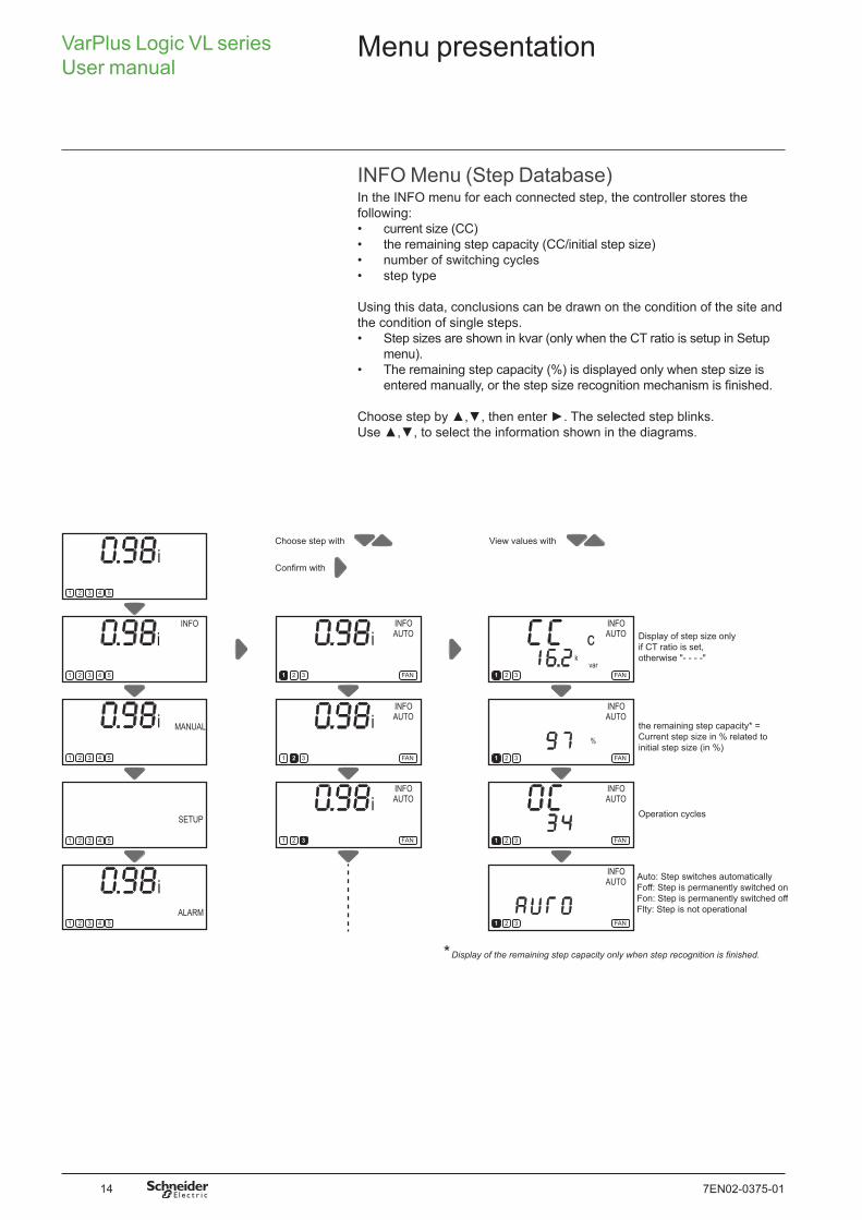
INFO Menu (Step Database)In the INFO menu for each connected step, the controller stores the following: • current size (CC)• the remaining step capacity (CC/initial step size)• number of switching cycles• step type
Using this data, conclusions can be drawn on the condition of the site and the condition of single steps.• Step sizes are shown in kvar (only when the CT ratio is setup in Setup
menu).• The remaining step capacity (%) is displayed only when step size is
entered manually, or the step size recognition mechanism is finished.
Choose step by ▲,▼, then enter ►. The selected step blinks.Use ▲,▼, to select the information shown in the diagrams.
Display of step size only if CT ratio is set, otherwise "- - - -"
View values withChoose step with
Confirm with
the remaining step capacity* =Current step size in % related to initial step size (in %)
Operation cycles
Auto: Step switches automaticallyFoff: Step is permanently switched onFon: Step is permanently switched offFlty: Step is not operational
INFOAUTO
FAN
INFOAUTOc
kvar
FAN
INFOAUTO
FAN
i
1 2 3 4 5
32
INFOAUTO
1 FAN
i
321
INFOAUTO
%
FAN321
321
321
3
INFOAUTO
1 2 FAN
i
INFOAUTO
1 2 3 FAN
i
INFO
i
1 2 3 4 5
MANUALi
1 2 3 4 5
SETUP
1 2 3 4 5
ALARM
i
1 2 3 4 5
* Display of the remaining step capacity only when step recognition is finished.

157EN02-0375-01
VarPlus Logic VL series User manual
Menu for MANUAL operation • To enter manual mode, select MANUAL from the main menu and
press ► for 3 seconds. By entering the submenu, the automatic control is stopped and the outputs can be switched manually.
• Use the ▲,▼ keys to select the step. Change the switching state by pressing the ► key.
Important Information• Manual operation cannot be opened if the controller is in LIFO control
mode and Ai is active.• After the controller switches off an active step, the discharge time
is active. The step can be switched on manually, only when the discharge time has passed.
• Manual switching is only possible when the measurement voltage is in the allowed range. Otherwise, the over- and under-voltage protection blocks this function.
• THD U-alarm, over temperature alarm, overload current ratio alarm and the hunting alarm prevents step switching in manual mode.
• Only steps with step type AUTO can be switched.• After leaving the MANUAL menu, the controller will restart in AUTO
mode. The controller returns to AUTO mode after 10 minutes without any action on the navigation keys.
Menu presentation
i
1 2 3 4 5
INFO
i
1 2 3 4 5
MANUALi
1 2 3 4 5
SETUP
1 2 3 4 5
ALARM
i
1 2 3 4 5
Choose step with
At each switching operation thecurrent PF is shown
Switch off / on with
Push
MANUALi
1 2 3 4 5
MANUAL
2
i
1 3 4 5
MANUALi
1 3 4 5
MANUAL
1
i
2 3 4 5
for 3seconds
MANUAL
1 2 3 4 5 12
c
• Step 2 is opened.• To switch on again step
2, push ►: the step will be close after discharge time, only.
• Step 12 is closed.• To switch off again step 12, push ►.

16 7EN02-0375-01
VarPlus Logic VL series User manual
Menu presentation
i
1 2 3 4 5
VSETUP
SETUP
SETUP
SETUP
INFO
i
1 2 3 4 5
MANUALi
1 2 3 4 5
SETUP
1 2 3 4 5
ALARM
i
1 2 3 4 5
SETUP
SETUP
SETUP
SETUPi
SETUP
s SETUP
SETUP
Ct ratio
Automaticinitialization
PFC controlmode
Cos phi1Target
Switchingtimeinterval
Step type[1- - - -max]
Advanced menu
LL Voltage
SETUP Menu (Quick start)The controller will start regulation if the nominal voltage set in the controller matches the voltage of the system. If your system is not 400 V, you must set the nominal voltage. The factory setting 400 V and all other settings are for optimal adaptation to the conditions of the system and to display system data appropriately.To change a setting, press the ► key.• Change the values with ▲,▼ and confirm with ►.• When you start the auto-initialization, the controller checks the
connection of the measurement and outputs.• At the end of the auto-initialization, the controller goes to Automatic
mode and displays AUTO.Note: All parameters of submenu 100 are also available in the sections 200 to 700 of Advanced menu, for example: Un = 201.

177EN02-0375-01
VarPlus Logic VL series User manual
Menu ALARMAlarm listThe table below gives an overview of all possible error codes. See more details about alarm settings in the section "500 Alarm Setup" on page 21.
List of alarmAI/Abrt ALARM This alarm is displayed when Auto-Initialization (AI) is aborted.
PFC control is moved to Off (regulation is stopped). U ALARM Measured voltage is outside the voltage tolerance limit.
Control is immediately stopped until voltage comes back into the tolerance limit.I LO ALARM Measured current is too low (less than 15 mA). All steps are opened in succession.I Hi ALARM Measured current is too high (more than 6 A). No action on control.PFC ALARM Under or over compensation, the controller cannot achieve the target Cos φ. No action on control.HAr ALARM THDU limit is exceeded.
Steps are switched off until the alarm condition disappears. Steps remain locked for 30 minutes.StEP/FLtY ALARM
One or more steps are broken. Faulty steps are blinking with the alarm message. Steps are locked for 24 hours.
SPL/Nr ALARM One or more steps have fallen below 75% of initial power: risk of resonance for capacitor bank with detuned reactor.Step number and error code will flash alternately. Steps identified as "SPL" are moved to Fix Off.
Thi ALARM The temperature limit (temperature 2) is exceeded. Steps are switched off successively until the alarm condition disappears. Steps remain locked for 30 minutes.
OPH ALARM Maximum number of hours of operation has been exceeded. Maintenance should be planned on the equipment.
OPC/Nr ALARM Maximum number of operation cycles has been exceeded for one or more steps.Maintenance should be planned on the equipment.
OL ALARM The capacitor overload current ratio is exceeded. Steps are switched off until the alarm condition disappears. Steps remain locked for 30 minutes.
HU ALARM One or more steps have exceeded the hunting limit.Step number and error code will flash alternately. Steps in alarm are moved to Fix Off.
Current Alarms When an alarm is active, ALARM and the error code flashes alternately on the display. When the alarm condition disappears, the display stops flashing.
Alarm log The last five alarms are logged in the Alarm menu. To view the alarms in the log, press the ► key. Change the values with ▲ and ▼. To reset Alarm log, press ▲ and ▼ simultaneously for 3 seconds.
Menu presentation
MANUALi
1 2 3 4 5
ALARM
ALARM
ALARM
ALARM
i
1 2 3 4 5
INFO
i
1 2 3 4 5
SETUP
1 2 3 4 5
ALARM
i
1 2 3 4 5
ALARM
18 7EN02-0375-01
VarPlus Logic VL series User manual
Advanced menu presentation
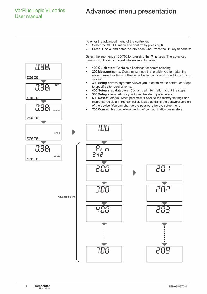
To enter the advanced menu of the controller:1. Select the SETUP menu and confirm by pressing ►.2. Press ▼ or ▲ and enter the PIN code 242. Press the ► key to confirm.
Select the submenus 100-700 by pressing the ▼ ▲ keys. The advanced menu of controller is divided into seven submenus: • 100 Quick start: Contains all settings for commissioning.• 200 Measurements: Contains settings that enable you to match the
measurement settings of the controller to the network conditions of your system.
• 300 Setup control system: Allows you to optimize the control or adapt to specific site requirements.
• 400 Setup step database: Contains all information about the steps.• 500 Setup alarm: Allows you to set the alarm parameters.• 600 Reset: Lets you reset parameters back to the factory settings and
clears stored data in the controller. It also contains the software version of the device. You can change the password for the setup menu.
• 700 Communication: Allows setting of communication parameters.
i
1 2 3 4 5
INFO
i
1 2 3 4 5
MANUALi
1 2 3 4 5
SETUP
1 2 3 4 5
ALARM
i
1 2 3 4 5
Advanced menu

197EN02-0375-01
VarPlus Logic VL series User manual
Advanced menu presentation
100 Quick start menuContains all information for commissioning.
Menu Function Range Default setting
Un (ph-ph) NOMINAL VOLTAGE = PHASE - PHASEDefines the nominal voltage of the system. Several parameters use the voltage setting:• threshold levels for under voltage and over voltage• ratings of the capacitor sizes in step database, which are used for control and
monitoring• capacitor sizes are rated to the nominal voltage and are stored in step database
100...242000 V 400 V
Ct CT-FACTORCT FACTOR is the ratio of current transformer (For example, 1000/5 = ratio 200).
1...9600 1
Ai START AUTO-INITIALIZATIONYes = starts auto-initializing.Automatic initialization switches all outputs one by one. During the test, it checks which outputs are connected and will correct the phase setting if voltage and current are miswired. Automatic initialization works only when capacitors are used for compensation. You must have an inductive load to be able to start the automatic initialization. The Ai feature will not work (may select incorrect settings, which will cause incorrect measurements and incorrect switching of the outputs.), if the controller has to switch reactors for compensation of a capacitive load. The Ai feature works best when load conditions are stable. During a new auto-initialization, steps with step type Fon will not be considered.Steps with step type "FON" will be not considered in case of new auto-initialization.
Yes/No (no setting)
PFC START / STOP / HOLD PF-CONTROLThe following options are available:• On: Control is in automatic mode.• Off: Control stops and active steps are disconnected in succession.• Hold: Control stops and active steps remain switched on.If you select Off or Hold, the controller shows PFC in the display alternating with Off or Hold. To start the control, select On.
On/Off/Hold On
CP1 Cos φ1This is the setting for target Cos φ1. It will be valid during normal operation.
0.70 c...0.70 i 0.95i
St SWITCH INTERVALThe switch interval is the time delay between switching steps in regulation.The switch interval has two different functions:• Building the average of the reactive power during the switching time interval. • Protecting the contactors by reducing the number of switching cycles.Note: if HV parameter (315) is selected, minimum time for the switch interval is 10 s and the default setting is moved to 120 s.
1...6500 s 10 s
Out TYPE OF OUTPUTIf step size recognition is active, you can leave the default setting. Active recognition is shown as Yes in menu 308. It will be automatically detected during Ai or during the step size recognition sequence.If the step size recognition is disabled, or if you want to force a step to Fon or Foff, you must configure the type of output. Disabled is shown as No in menu 308 of the advanced menus.The following step types can be selected:• Auto = Step is used for normal regulation algorithm.• Fon = Step is permanently switched on (step is still monitored and shut down in
critical situations).• Foff = Step is permanently switched off. Select this setting for used steps to avoid
unnecessary alarm.• Flty = if parameter Lock Faulty Step (309) is set to Yes, a step switched three times
without success is declared not operational and is no longer used for automatic control for 24 hours or until controller is restarted. After you have resolved the issue, a step stored as "flty" can be reset to the desired step type in this menu.
Auto/FOn/FOff Auto
20 7EN02-0375-01
VarPlus Logic VL series User manual
Advanced menu presentation
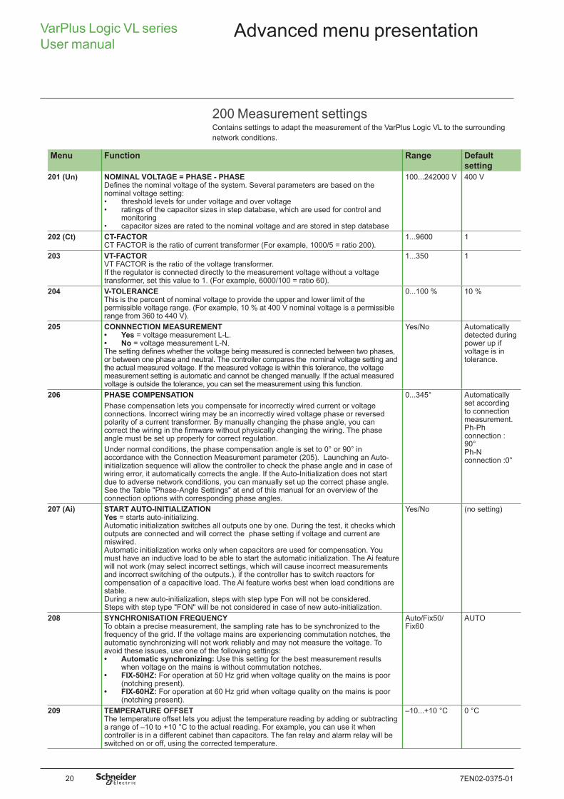
200 Measurement settingsContains settings to adapt the measurement of the VarPlus Logic VL to the surrounding network conditions.
Menu Function Range Default setting
201 (Un) NOMINAL VOLTAGE = PHASE - PHASEDefines the nominal voltage of the system. Several parameters are based on the nominal voltage setting: • threshold levels for under voltage and over voltage• ratings of the capacitor sizes in step database, which are used for control and
monitoring• capacitor sizes are rated to the nominal voltage and are stored in step database
100...242000 V 400 V
202 (Ct) CT-FACTORCT FACTOR is the ratio of current transformer (For example, 1000/5 = ratio 200).
1...9600 1
203 VT-FACTORVT FACTOR is the ratio of the voltage transformer. If the regulator is connected directly to the measurement voltage without a voltage transformer, set this value to 1. (For example, 6000/100 = ratio 60).
1...350 1
204 V-TOLERANCEThis is the percent of nominal voltage to provide the upper and lower limit of the permissible voltage range. (For example, 10 % at 400 V nominal voltage is a permissible range from 360 to 440 V).
0...100 % 10 %
205 CONNNECTION MEASUREMENT• Yes = voltage measurement L-L.• No = voltage measurement L-N. The setting defines whether the voltage being measured is connected between two phases, or between one phase and neutral. The controller compares the nominal voltage setting and the actual measured voltage. If the measured voltage is within this tolerance, the voltage measurement setting is automatic and cannot be changed manually. If the actual measured voltage is outside the tolerance, you can set the measurement using this function.
Yes/No Automatically detected during power up if voltage is in tolerance.
206 PHASE COMPENSATIONPhase compensation lets you compensate for incorrectly wired current or voltage connections. Incorrect wiring may be an incorrectly wired voltage phase or reversed polarity of a current transformer. By manually changing the phase angle, you can correct the wiring in the firmware without physically changing the wiring. The phase angle must be set up properly for correct regulation. Under normal conditions, the phase compensation angle is set to 0° or 90° in accordance with the Connection Measurement parameter (205). Launching an Auto-initialization sequence will allow the controller to check the phase angle and in case of wiring error, it automatically corrects the angle. If the Auto-Initialization does not start due to adverse network conditions, you can manually set up the correct phase angle. See the Table "Phase-Angle Settings" at end of this manual for an overview of the connection options with corresponding phase angles.
0...345° Automatically set according to connection measurement. Ph-Ph connection : 90°Ph-N connection :0°
207 (Ai) START AUTO-INITIALIZATIONYes = starts auto-initializing.Automatic initialization switches all outputs one by one. During the test, it checks which outputs are connected and will correct the phase setting if voltage and current are miswired. Automatic initialization works only when capacitors are used for compensation. You must have an inductive load to be able to start the automatic initialization. The Ai feature will not work (may select incorrect settings, which will cause incorrect measurements and incorrect switching of the outputs.), if the controller has to switch reactors for compensation of a capacitive load. The Ai feature works best when load conditions are stable. During a new auto-initialization, steps with step type Fon will not be considered.Steps with step type "FON" will be not considered in case of new auto-initialization.
Yes/No (no setting)
208 SYNCHRONISATION FREQUENCYTo obtain a precise measurement, the sampling rate has to be synchronized to the frequency of the grid. If the voltage mains are experiencing commutation notches, the automatic synchronizing will not work reliably and may not measure the voltage. To avoid these issues, use one of the following settings:• Automatic synchronizing: Use this setting for the best measurement results
when voltage on the mains is without commutation notches.• FIX-50HZ: For operation at 50 Hz grid when voltage quality on the mains is poor
(notching present).• FIX-60HZ: For operation at 60 Hz grid when voltage quality on the mains is poor
(notching present).
Auto/Fix50/Fix60
AUTO
209 TEMPERATURE OFFSETThe temperature offset lets you adjust the temperature reading by adding or subtracting a range of –10 to +10 °C to the actual reading. For example, you can use it when controller is in a different cabinet than capacitors. The fan relay and alarm relay will be switched on or off, using the corrected temperature.
–10...+10 °C 0 °C
217EN02-0375-01
VarPlus Logic VL series User manual
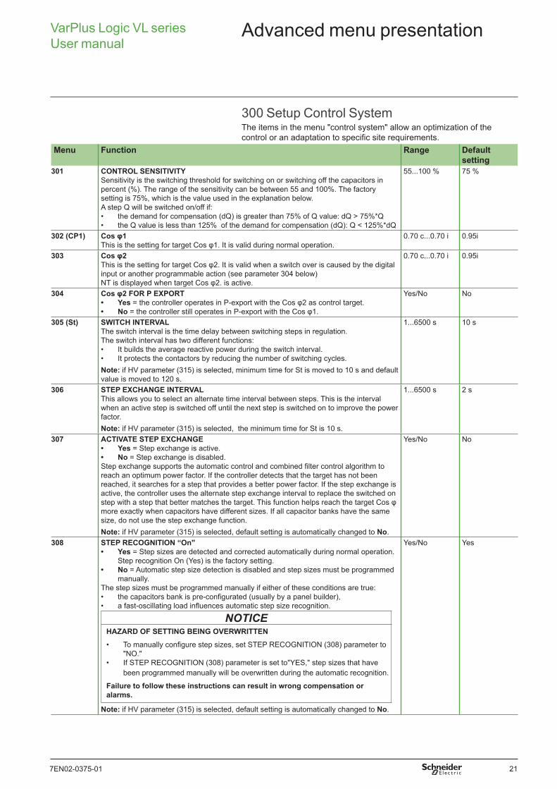
300 Setup Control SystemThe items in the menu "control system" allow an optimization of the control or an adaptation to specific site requirements.
Menu Function Range Default setting
301 CONTROL SENSITIVITYSensitivity is the switching threshold for switching on or switching off the capacitors in percent (%). The range of the sensitivity can be between 55 and 100%. The factory setting is 75%, which is the value used in the explanation below.A step Q will be switched on/off if:• the demand for compensation (dQ) is greater than 75% of Q value: dQ > 75%*Q • the Q value is less than 125% of the demand for compensation (dQ): Q < 125%*dQ
55...100 % 75 %
302 (CP1) Cos φ1This is the setting for target Cos φ1. It is valid during normal operation.
0.70 c...0.70 i 0.95i
303 Cos φ2This is the setting for target Cos φ2. It is valid when a switch over is caused by the digital input or another programmable action (see parameter 304 below) NT is displayed when target Cos φ2. is active.
0.70 c...0.70 i 0.95i
304 Cos φ2 FOR P EXPORT• Yes = the controller operates in P-export with the Cos φ2 as control target.• No = the controller still operates in P-export with the Cos φ1.
Yes/No No
305 (St) SWITCH INTERVALThe switch interval is the time delay between switching steps in regulation.The switch interval has two different functions:• It builds the average reactive power during the switch interval.• It protects the contactors by reducing the number of switching cycles.Note: if HV parameter (315) is selected, minimum time for St is moved to 10 s and default value is moved to 120 s.
1...6500 s 10 s
306 STEP EXCHANGE INTERVALThis allows you to select an alternate time interval between steps. This is the interval when an active step is switched off until the next step is switched on to improve the power factor. Note: if HV parameter (315) is selected, the minimum time for St is 10 s.
1...6500 s 2 s
307 ACTIVATE STEP EXCHANGE• Yes = Step exchange is active.• No = Step exchange is disabled.Step exchange supports the automatic control and combined filter control algorithm to reach an optimum power factor. If the controller detects that the target has not been reached, it searches for a step that provides a better power factor. If the step exchange is active, the controller uses the alternate step exchange interval to replace the switched on step with a step that better matches the target. This function helps reach the target Cos φ more exactly when capacitors have different sizes. If all capacitor banks have the same size, do not use the step exchange function.Note: if HV parameter (315) is selected, default setting is automatically changed to No.
Yes/No No
308 STEP RECOGNITION “On"• Yes = Step sizes are detected and corrected automatically during normal operation.
Step recognition On (Yes) is the factory setting.• No = Automatic step size detection is disabled and step sizes must be programmed
manually. The step sizes must be programmed manually if either of these conditions are true: • the capacitors bank is pre-configurated (usually by a panel builder),• a fast-oscillating load influences automatic step size recognition.
NOTICEHAZARD OF SETTING BEING OVERWRITTEN
• To manually configure step sizes, set STEP RECOGNITION (308) parameter to "NO."
• If STEP RECOGNITION (308) parameter is set to"YES," step sizes that have been programmed manually will be overwritten during the automatic recognition.
Failure to follow these instructions can result in wrong compensation or alarms.
Note: if HV parameter (315) is selected, default setting is automatically changed to No.
Yes/No Yes
Advanced menu presentation

22 7EN02-0375-01
VarPlus Logic VL series User manual
Advanced menu presentation
Menu Function Range Default setting
309 LOCK DEFECTIVE STEPS• Yes = If a step is switched three times without a measurable network reaction, the
controller blocks the step and does not use it for control. The controller recognizes the step output as being inoperable, blinks in the display, and sets the value to "Flty" (faulty) in the step type menu (403). The controller will continue to test inoperable steps every 24 hours or after the controller is restarted.
• No = Steps are connected even if no network reaction is measurable. This results in unnecessary switching cycles.
Yes/No Yes
310 (PFC) START / STOP / HOLD PF-CONTROLStopping the automatic control. The following options are available:• On: Control in automatic mode• Off: Control stops and active steps are disconnected in succession.• Hold: Control Stops and active steps remain switched on.If "Off" or "Hold" is selected, the text flashes in the display as "PFC" alternating with "Off" or "Hold." To start the control, select "On."
When the auto initialization (AI) aborts, the controller is changed to Off. After troubleshooting to solve issues, you can reset the PFC controller back to automatic mode "On."
On/Off/Hold On
311 CONTROL ALGORITHM1=Automatic: The controller works on the principle of “best fit.“ Before it performs a switching operation, it compares all capacitor sizes in the step database to the control deviation.The available step with the best results will be switched.2=LIFO: “Last In, First Out” The controller starts regulation with step 1 and switches subsequent outputs step-by-step, switching on and off alternatively.3=Progressive: If required, the controller switches several steps in sequence using a 1s switching time, independent of the set switching time. Discharge time still applies in accordance with parameter 401.Furthermore, the automatic step-size detection is disabled and you must manually set up the step size. The input of the step sizes should be as accurate as possible, otherwise, the regulator will tend to oscillate. By selecting the "Progressive" algorithm and using a different algorithm, you can re-enable the set switching time and the step size detection.
1/2/3 1 (Automatic)
312 OFFSET REACTIVE POWERThis feature lets you compensates for a permanent reactive load that cannot be measured, such as a transformer.The offset of reactive power affects the readings of these measured values: current, reactive power, control deviation, apparent power, power factor PF, and Cos φ.Maximum value that can be set is 9.9 Mvar.
C999,9..i999,9 0 kvar
313 ASYMMETRIC FACTORASYMMETRIC FACTOR of switch interval. The factor is the ratio between switch interval for switching on and switching off. This setting does not affect the switch interval for the step exchange.• X = 1 = equal.• X = +2 to +127: delay switching off = switch interval multiplied by X.• X = –2 to –127: delay switching on = switch interval multiplied by X.
–127...127 1
314 Q CAPACITIVE STEPS TURN Off• Yes = As soon as a capacitive condition is recognized, the controller switches off
without adhering to the switching time, which is the necessary step power to prevent leading network conditions.
• No = The controller works only with the set target Cos φ.
CAUTIONHAZARD OF HIGH STEP SWICHING RATE (HUNTING) IF THIS PARAMETER IS USED WITH A COS PHI SETTING CLOSE TO 1
If you want to use this parameter, make a test for a short period to check comportment on the steps.
Failure to follow this recommendation can result in equipment damage.
Yes/No No
315 HV CONFIGURATIONYes = some default parameters are automatically moved to a more appropriate value: • Discharge time (401) is set at 600 s, switching interval (305) is set a 120 s. • Automatic step size recognition (308) and step exchange (307) are disabled.• Delay before all calculation when a step is switched On or Off is move from 300 ms
to 8 s to be compatible with all type of HV contactors.
Yes/No No
237EN02-0375-01
VarPlus Logic VL series User manual
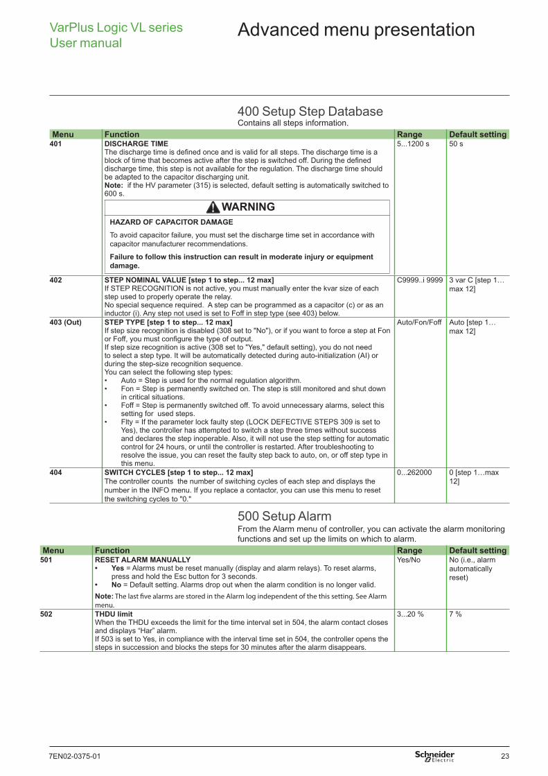
400 Setup Step DatabaseContains all steps information.
Menu Function Range Default setting401 DISCHARGE TIME
The discharge time is defined once and is valid for all steps. The discharge time is ablock of time that becomes active after the step is switched off. During the defined discharge time, this step is not available for the regulation. The discharge time should be adapted to the capacitor discharging unit.Note: if the HV parameter (315) is selected, default setting is automatically switched to 600 s.
WARNINGHAZARD OF CAPACITOR DAMAGE
To avoid capacitor failure, you must set the discharge time set in accordance with capacitor manufacturer recommendations.
Failure to follow this instruction can result in moderate injury or equipment damage.
5...1200 s 50 s
402 STEP NOMINAL VALUE [step 1 to step... 12 max]If STEP RECOGNITION is not active, you must manually enter the kvar size of each step used to properly operate the relay.No special sequence required. A step can be programmed as a capacitor (c) or as an inductor (i). Any step not used is set to Foff in step type (see 403) below.
C9999..i 9999 3 var C [step 1…max 12]
403 (Out) STEP TYPE [step 1 to step... 12 max]If step size recognition is disabled (308 set to "No"), or if you want to force a step at Fon or Foff, you must configure the type of output.If step size recognition is active (308 set to "Yes," default setting), you do not need to select a step type. It will be automatically detected during auto-initialization (AI) or during the step-size recognition sequence.You can select the following step types:• Auto = Step is used for the normal regulation algorithm.• Fon = Step is permanently switched on. The step is still monitored and shut down
in critical situations.• Foff = Step is permanently switched off. To avoid unnecessary alarms, select this
setting for used steps.• Flty = If the parameter lock faulty step (LOCK DEFECTIVE STEPS 309 is set to
Yes), the controller has attempted to switch a step three times without success and declares the step inoperable. Also, it will not use the step setting for automatic control for 24 hours, or until the controller is restarted. After troubleshooting to resolve the issue, you can reset the faulty step back to auto, on, or off step type in this menu.
Auto/Fon/Foff Auto [step 1…max 12]
404 SWITCH CYCLES [step 1 to step... 12 max]The controller counts the number of switching cycles of each step and displays the number in the INFO menu. If you replace a contactor, you can use this menu to reset the switching cycles to "0."
0...262000 0 [step 1…max 12]
500 Setup AlarmFrom the Alarm menu of controller, you can activate the alarm monitoring functions and set up the limits on which to alarm.
Menu Function Range Default setting501 RESET ALARM MANUALLY
• Yes = Alarms must be reset manually (display and alarm relays). To reset alarms, press and hold the Esc button for 3 seconds.
• No = Default setting. Alarms drop out when the alarm condition is no longer valid. Note: The last five alarms are stored in the Alarm log independent of the this setting. See Alarm menu.
Yes/No No (i.e., alarm automatically reset)
502 THDU limitWhen the THDU exceeds the limit for the time interval set in 504, the alarm contact closes and displays “Har” alarm.If 503 is set to Yes, in compliance with the interval time set in 504, the controller opens the steps in succession and blocks the steps for 30 minutes after the alarm disappears.
3...20 % 7 %
Advanced menu presentation

24 7EN02-0375-01
VarPlus Logic VL series User manual
Menu Function Range Default setting503 DISCONNECT STEPS ON THDU, CAPACITOR OVERLOAD CURRENT RATIO
AND TEMPERATURE ALARMS• Yes = When the set threshold for THDU, capacitor overload current ratio, and
temperature are exceeded, all active steps are switched off in succession and blocked for 30 minutes after alarm disappears. The alarm disappears after the interval of time defined in 504.
• No = These alarms will not affect the control.
WARNINGHAZARD OF EQUIPMENT DAMAGE IF THIS PARAMETER IS DISCONNECTED
To avoid equipment damage or nuisance alarms, do not disable control for these alarms. Instead, check the equipment on first alarm and make adjustments to the alarm settings that best match your equipment.
Failure to follow this instruction can result in equipment damage.
Yes/No Yes
504 INTERVAL TIME BEFORE TRIGGER FOR THDU, OVERLOAD CURRENT RATIO AND TEMPERATURE ALARMS Interval of time after exceeding the limit for THDU, overload current ratio, and temperature alarms. This delay is applied to actions on control or alarm relay, and before the opening of each step.
1...255 s 60 s (for THDU, OL ratio and temperature alarm)
505 FREEZE CONTROL IF I LOW ALARM• Yes = When the current measured drops below 15 mA, the control freezes.
All active steps remain switched on.• No = Measuring current falls below 15 mA, the controller shuts down all active steps
successively.
Yes/No No
506 SERVICE ALARM• Yes = the alarm contact closes when the defined maximum switching cycles for one
or more steps (507) have been exceeded, or if the set threshold for operation hours (508) is reached.
• No = no alarm when the maximum switching cycles or operation hours is exceeded. That alarm has no action on the control.
Yes/No Yes
507 SWITCHING CYCLES LIMITMaximum switching cycles before the service alarm is activated. Alarm displays as OPC (operation cycles) alarm.After maintenance, the alarm can be reset using parameter 404.
1...262000 100 k
508 OPERATION HOURS LIMIT (global PFC bank) Maximum hours of operation before service alarm. Alarm displays as OPH (operation hours) alarm.After maintenance, the alarm can be reset using parameter 603.
1...65535 h 65.5 K hours (7 years)
509 CAPACITOR OVERLOAD CURRENT RATIO LIMITWhen the capacitor overload current ratio exceeds the limit for the defined time interval in 504, the alarm contact is closed and the display indicates “OL” alarm. The OL alarm is based on a calculation from the voltage distortion spectrum to inform you about possible high RMS current in the capacitor.If 503 is set to Yes (default setting) in compliance with the interval time defined in 504, the steps will be switched off successively and blocked for 30 minutes after the alarm disappears.
1...1.5 1.3
510 DIGITAL INPUT ACTIVE AT HIGH LEVEL• Yes = Digital input (to target Cos φ2) is active when the digital input is closed.• No = Digital input (to target Cos φ2) is active when digital input is opened.
Yes/No Yes
511 TEMPERATURE 1 LIMIT (FAN)When the temperature exceeds temperature 1 threshold, the controller closes the fan contact and displays “FAN.”Fan relay will open if temperature decreases 5 °C below the limit.
3 °C … (Temp2 - 5 °C)
30 °C
512 TEMPERATURE 2 LIMIT (ALARM)When the temperature exceeds the threshold, the alarm contact is closed and displays "thi" alarm.If 503 is set to Yes (default setting), in compliance with the interval time set in 504, steps will be switched off successively and blocked for 30 min after the alarm disappears.Fan relay will open if temperature decreases 5 °C below the limit.
(Temp1 + 5 °C) ... 60 °C
50 °C
513 PFC ALARM (target Cos φ can not be archived)• Yes = alarm is triggered after "75 * switching time" with ▲Q > smallest step (Over /
under compensation). Controller closes the alarm contact and indicates "PFC" Alarm in the Display. This control is enabled only after the step recognition is complete.
• No = no monitoring for over / under compensation.That alarm has no action on control.
Yes/No Yes
514 DEFECTIVE STEP ALARM• Yes = after 3 unsuccessful switching actions, the alarm is triggered. The controller
closes the alarm contact and displays "STEP" Alarm / "FLty" alarm. Steps recognized as defective flash in the step indication. If parameter 309 (lock faulty steps) is set at "Yes," the step is blocked for 24 hours or until the controller restarts.
• No = alarm disabled (control is still active when menu item 309 is set to "Yes").
Yes/No Yes
Advanced menu presentation

257EN02-0375-01
VarPlus Logic VL series User manual
Advanced menu presentation
600 Reset menuAllows you to reset all settings made by the controller and stored data. Additionally, it contains the software version of the device.
Menu Function Range Default setting
601 RESET SETTINGSSets all settings made to factory settings (except step database parameters 402, 403, 404)
Yes/No
602 RESET STEP DATABASESets all step data base parameters (402, 403, 404) to factory settings
WARNINGHAZARD OF DATA BEING OVERWRITTEN
If step size detection is set to Off and steps have been entered manually, reset step database will erase these values.
Failure to follow this instruction can result in death or serious injury.
Yes/No
603 RESET OPERATION HOURSSets the counter for operation hours to "0." Note: to reset the switching cycles of each step, see "Info" menu.
Yes/No
604 RESET AVERAGE TRUE PFReset the average PF.
Yes/No
605 RESET MAX. TEMPERATUREReset the highest measured Temperature (Thi).
Yes/No
606 RESET ALARMSReset all upcoming alarms and log alarms
Yes/No
607 DISPLAY SOFTWARE VERSIONContains the software version of the device.
xxx.xxx.xxx
608 ADjUSTMENT OF THE SETUP PASSWORDYou can add your own password. However, the factory password remains active.
242
700 Communication ParametersAllows you to set Communication parameters
Menu Function Range Default setting
701 SPEED 1.2 K...115.2 K 19.2 K702 PARITY None -
Even-OddEven
703 SLAVE NUMBER 1.... 247 1
515 STEP POWER LOSS ALARM• Yes = if the current step size is less than 75% of the initial size, the controller closes
the alarm contact and shows the error with output number "SPL" Alarm / "Nr" alarm in the display. Step type is changed to fixed off (Foff).
• No = Power loss of the capacitors is not monitored. There is no action on control or alarm.
WARNINGHAZARD OF EQUIPMENT DAMAGE
A capacitor loss can cause resonance on the system when a detuned reactor is used. To avoid this risk, do not disable the Step Power Loss alarm.
Failure to follow this instruction can result in equipment damage.
Yes/No Yes
516 HUNTING ALARM• Yes = If the controller detects that regulation is unstable, the controller closes the
alarm contact and indicates the error with output number “HU” Alarm / "Nr" Alarm on the display. The step is declared inoperable and moved to Fix off and will not be used for control.
• No = Hunting alarm is not monitored. There is no action on control or alarm.
Yes/No Yes
517 HUNTING LIMITAlarm if regulation is declared as unstable: limit corresponds to a maximum number of switching attempts during a period of 10 * discharge time.
1... 10 7

26 7EN02-0375-01
VarPlus Logic VL series User manual
Preliminary operation1. Disconnect panel from mains voltage and check that the voltage is
off.2. Verify that PFC controller metal case is connected to ‘PE’ by earth
protection cable.3. Verify that the voltage and CT current input are suitable for the PFC
controller.4. Verify that all PFC controller inputs and outputs are connected
according to wiring diagram with suitable protection (see chapter Wiring).
5. Verify CT position and proper connection (CT/P1 towards incoming feeder, CT/P2 towards load).
6. Remove short-circuit connection from CT.
Default configuration (Step size recognition On) The capacitor size of each steps can be entered:• manually for Panel builder pre-configuration: step size recognition
parameter Off• automatically detected by the Step recognition mechanism: step size
recognition parameter OnBy default, the VarPlus Logic controller is configured with step size recognition On. In a 400 V system, this configuration allows the controller to start operation without any changes to the configuration settings. However, to have I, S, P, Q measurements and capacitors step size displayed (in Info menu), you must set up the CT ratio.
Normal operation(switching ≥ 51)
&Step size monitoring
(measurement ofcurrent capacitor size
«CC»)
Step recognitionmechanism
(first 50 switching)
Step recognition ON(auto-rec)
Auto modeimmediatly starts.
Reset stepdatabase
CT or VT ratiochanged by user?
NO YES
Normaloperation(including
step recognition)
Commissioning
277EN02-0375-01
VarPlus Logic VL series User manual
Commissioning
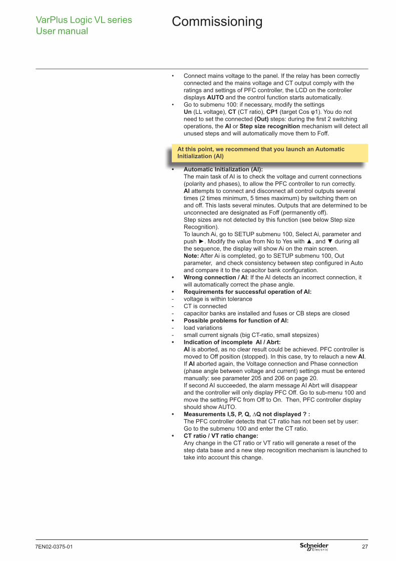
• Connect mains voltage to the panel. If the relay has been correctly connected and the mains voltage and CT output comply with the ratings and settings of PFC controller, the LCD on the controller displays AUTO and the control function starts automatically.
• Go to submenu 100: if necessary, modify the settings Un (LL voltage), CT (CT ratio), CP1 (target Cos φ1). You do not need to set the connected (Out) steps: during the first 2 switching operations, the AI or Step size recognition mechanism will detect all unused steps and will automatically move them to Foff.
At this point, we recommend that you launch an Automatic Initialization (AI)
• Automatic Initialization (AI): The main task of AI is to check the voltage and current connections (polarity and phases), to allow the PFC controller to run correctly. AI attempts to connect and disconnect all control outputs several times (2 times minimum, 5 times maximum) by switching them on and off. This lasts several minutes. Outputs that are determined to be unconnected are designated as Foff (permanently off). Step sizes are not detected by this function (see below Step size Recognition). To launch Ai, go to SETUP submenu 100, Select Ai, parameter and push ►. Modify the value from No to Yes with ▲, and ▼ during all the sequence, the display will show Ai on the main screen. Note: After Ai is completed, go to SETUP submenu 100, Out parameter, and check consistency between step configured in Auto and compare it to the capacitor bank configuration.
• Wrong connection / AI: If the AI detects an incorrect connection, it will automatically correct the phase angle.
• Requirements for successful operation of AI:- voltage is within tolerance- CT is connected - capacitor banks are installed and fuses or CB steps are closed• Possible problems for function of AI:- load variations- small current signals (big CT-ratio, small stepsizes)• Indication of incomplete AI / Abrt:
AI is aborted, as no clear result could be achieved. PFC controller is moved to Off position (stopped). In this case, try to relauch a new AI. If AI aborted again, the Voltage connection and Phase connection (phase angle between voltage and current) settings must be entered manually: see parameter 205 and 206 on page 20. If second AI succeeded, the alarm message AI Abrt will disappear and the controller will only display PFC Off. Go to sub-menu 100 and move the setting PFC from Off to On. Then, PFC controller display should show AUTO.
• Measurements I,S, P, Q, ∆Q not displayed ? : The PFC controller detects that CT ratio has not been set by user: Go to the submenu 100 and enter the CT ratio.
• CT ratio / VT ratio change: Any change in the CT ratio or VT ratio will generate a reset of the step data base and a new step recognition mechanism is launched to take into account this change.

28 7EN02-0375-01
VarPlus Logic VL series User manual
Step size entered manually (for panel builder pre-configuration)
Reset of currentcapacitor step size (cc)
to initial value
Normal operation&
Step size monitoring(measurement of
current capacitor size«CC»)
User can start controlby setting PFC to ON
PFC is OFF as long asuser has not entered
a CT ratio and step size
Step recognition OFF (manual)
CT or PT ratiochanged by user?
CT input
Step size input(initial value)
NOYES
NO
Normaloperation
YES
NO YES
Siteconfiguration
Panel builderpreconfiguration
Panel builder pre-configuration:• In Setup sub-menu 100 define Un (LL voltage). • In sub-menu 300, move the setting 308 (Step recognition On)
from Yes to No• In sub-menu 400, enter Step size of each capacitor connected in
402. Steps not used must be set as Off in 403. Customer site configuration: Go to the Setup sub- menu 100, check Un, enter CT ratio and CP1 (target Cos φ1). If necessary, adjust VT ratio (sub-menu 200, parameter 203)
At this point, we recommend that you launch an Automatic Initialization (AI)
Automatic Initialization (AI): The main task of AI is to check the voltage and current connections (polarity and phases), to allow the PFC controller to run correctly. AI attempts to connect and disconnect all control outputs several times (2 times minimum, 5 times maximum) by switching them on and off. This lasts several minutes. Outputs that are determined to be unconnected are designated as Foff (permanently off).
Commissioning
297EN02-0375-01
VarPlus Logic VL series User manual
Commissioning
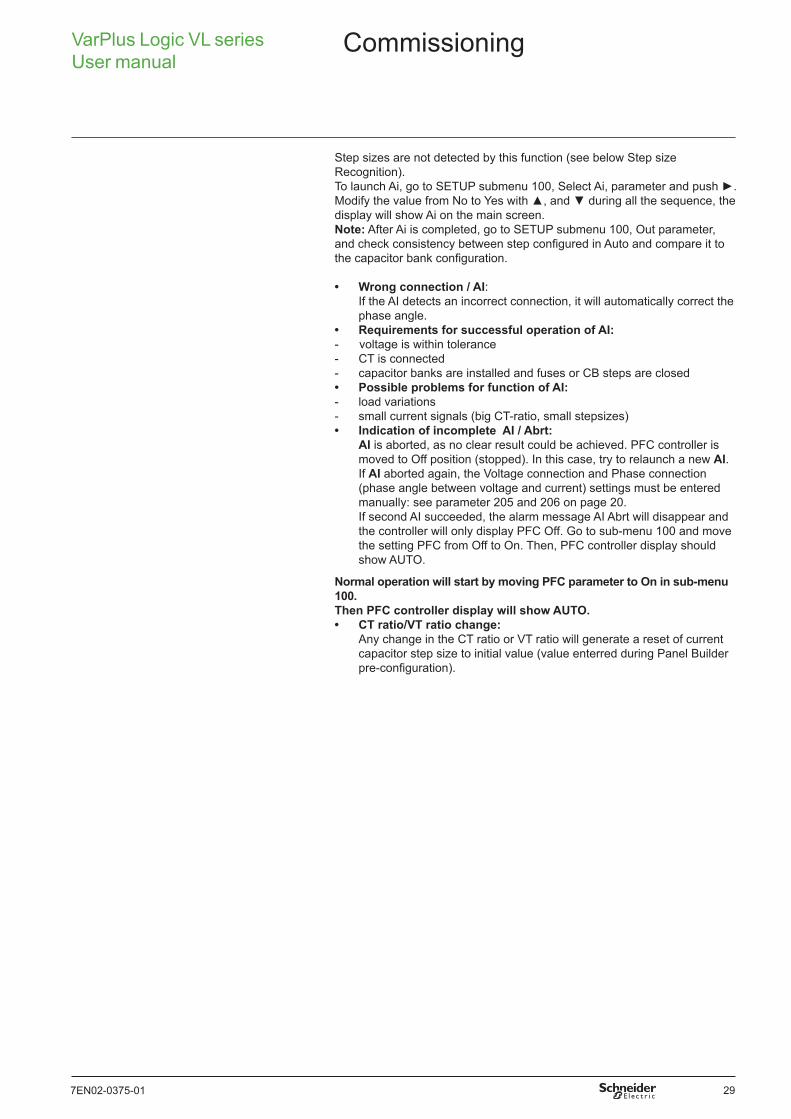
Step sizes are not detected by this function (see below Step size Recognition). To launch Ai, go to SETUP submenu 100, Select Ai, parameter and push ►. Modify the value from No to Yes with ▲, and ▼ during all the sequence, the display will show Ai on the main screen. Note: After Ai is completed, go to SETUP submenu 100, Out parameter, and check consistency between step configured in Auto and compare it to the capacitor bank configuration.
• Wrong connection / AI: If the AI detects an incorrect connection, it will automatically correct the phase angle.
• Requirements for successful operation of AI:- voltage is within tolerance- CT is connected - capacitor banks are installed and fuses or CB steps are closed• Possible problems for function of AI:- load variations- small current signals (big CT-ratio, small stepsizes)• Indication of incomplete AI / Abrt:
AI is aborted, as no clear result could be achieved. PFC controller is moved to Off position (stopped). In this case, try to relaunch a new AI. If AI aborted again, the Voltage connection and Phase connection (phase angle between voltage and current) settings must be entered manually: see parameter 205 and 206 on page 20. If second AI succeeded, the alarm message AI Abrt will disappear and the controller will only display PFC Off. Go to sub-menu 100 and move the setting PFC from Off to On. Then, PFC controller display should show AUTO.
Normal operation will start by moving PFC parameter to On in sub-menu 100. Then PFC controller display will show AUTO.• CT ratio/VT ratio change:
Any change in the CT ratio or VT ratio will generate a reset of current capacitor step size to initial value (value enterred during Panel Builder pre-configuration).
30 7EN02-0375-01
VarPlus Logic VL series User manual
Troubleshooting
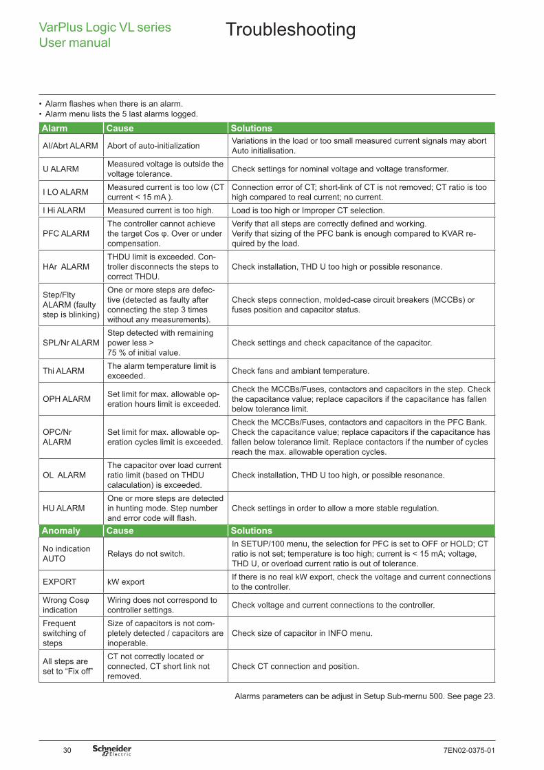
Alarm Cause Solutions
AI/Abrt ALARM Abort of auto-initialization Variations in the load or too small measured current signals may abort Auto initialisation.
U ALARM Measured voltage is outside the voltage tolerance. Check settings for nominal voltage and voltage transformer.
I LO ALARM Measured current is too low (CT current < 15 mA ).
Connection error of CT; short-link of CT is not removed; CT ratio is too high compared to real current; no current.
I Hi ALARM Measured current is too high. Load is too high or Improper CT selection.
PFC ALARMThe controller cannot achieve the target Cos φ. Over or under compensation.
Verify that all steps are correctly defined and working. Verify that sizing of the PFC bank is enough compared to KVAR re-quired by the load.
HAr ALARMTHDU limit is exceeded. Con-troller disconnects the steps to correct THDU.
Check installation, THD U too high or possible resonance.
Step/Flty ALARM (faulty step is blinking)
One or more steps are defec-tive (detected as faulty after connecting the step 3 times without any measurements).
Check steps connection, molded-case circuit breakers (MCCBs) or fuses position and capacitor status.
SPL/Nr ALARMStep detected with remaining power less > 75 % of initial value.
Check settings and check capacitance of the capacitor.
Thi ALARM The alarm temperature limit is exceeded. Check fans and ambiant temperature.
OPH ALARM Set limit for max. allowable op-eration hours limit is exceeded.
Check the MCCBs/Fuses, contactors and capacitors in the step. Check the capacitance value; replace capacitors if the capacitance has fallen below tolerance limit.
OPC/Nr ALARM
Set limit for max. allowable op-eration cycles limit is exceeded.
Check the MCCBs/Fuses, contactors and capacitors in the PFC Bank. Check the capacitance value; replace capacitors if the capacitance has fallen below tolerance limit. Replace contactors if the number of cycles reach the max. allowable operation cycles.
OL ALARMThe capacitor over load current ratio limit (based on THDU calaculation) is exceeded.
Check installation, THD U too high, or possible resonance.
HU ALARMOne or more steps are detected in hunting mode. Step number and error code will flash.
Check settings in order to allow a more stable regulation.
Anomaly Cause Solutions
No indication AUTO Relays do not switch.
In SETUP/100 menu, the selection for PFC is set to OFF or HOLD; CT ratio is not set; temperature is too high; current is < 15 mA; voltage, THD U, or overload current ratio is out of tolerance.
EXPORT kW export If there is no real kW export, check the voltage and current connections to the controller.
Wrong Cosφ indication
Wiring does not correspond to controller settings. Check voltage and current connections to the controller.
Frequent switching of steps
Size of capacitors is not com-pletely detected / capacitors are inoperable.
Check size of capacitor in INFO menu.
All steps are set to “Fix off”
CT not correctly located or connected, CT short link not removed.
Check CT connection and position.
Alarms parameters can be adjust in Setup Sub-mernu 500. See page 23.
• Alarm flashes when there is an alarm.• Alarm menu lists the 5 last alarms logged.
317EN02-0375-01
VarPlus Logic VL series User manual
Troubleshooting
Problems with the step recognitionSituation: The controller is used in a system with rapid changes in load conditions and has problems with the automatic step recognition.Solution:To solve this problem, turn off step recognition and enter the step sizes manually.Procedure:1. Stop control: Set item PFC to "Off" in menu 100 (quick start menu).2. Set item 308 (Step size recognition on), from “Yes” to "No" in the
advanced menu.3. Enter step sizes: Set the nominal value of the capacitors connected
at point 402 in the advanced menu. 4. Enter Step type: Sets all the steps that are automatically controlled
as AUTO at point 403 in the advanced menu. For problems with the step detection, it may happen that a connected step will be stored by the controller incorrectly as "FIX-Off." Therefore, the step type of each step should be controlled under the menu item "403." All steps of the automatic control used, must be use the step type "AUTO".
Reset inoperable steps (Faulty alarm)Situation: If the controller has a step recognized as "faulty" (3 switching operations without a result) and parameter 309 (locked faulty steps) is set at Yes (default value), it will be excluded for 24 hours from the regulation or until PFC controller restarts (voltage disconnection and reconnection). After this period, the step is tested again from the controller. If the controller can detect the step, it will again be included in the control. If not, the step is blocked again for 24 hours after 3 unsuccessful switching cycles. Inoperable steps are in the "INFO" menu with the step type designation "flty" and flashing in the step indication.
Procedure to reset an inoperable step:Select item "403" in advanced menu and use the ▼▲ buttons to select the corresponding step. Confirm with ► button and use the ▼▲ buttons to adjust step type "AUTO."
Step power loss and Hunting alarmWhen a step lost more than 25% of its initial power or when a step is detected as Hunting, the PFC controller will block the step (Fix off). To reset a step:1. Determine the reason for the loss or hunting and fix the issue. 2. Manually reset the nominal step size. Select the step in the 402
menu and select the nominal step size. 3. Select item "403" in advanced menu and use the ▼▲ buttons to
select the corresponding step. Confirm with ► button and use the ▼▲ buttons to adjust step type "AUTO."
4. If the step contactor is replaced, select item 404 in advanced menu and use the ▼▲ buttons to select the corresponding step. Confirm with the ► button and move the accumulated switching cycle to "0."
32 7EN02-0375-01
VarPlus Logic VL series User manual
The VarPlus Logic controller contains three different control algorithms (SETUP parameter 311) • Automatic: The controller works on the principle of “best fit.“ Before a
switching operation, all capacitor sizes in the step database are compared with control deviation. The available step that gives the best results will be switched.
• LIFO: “Last In, First Out” The controller starts regulation with step 1 and switches each output, one by one. Switching off is done vice versa.
• Progressive: If required, the controller switches several steps in sequence with a switching time always at 1s (independently of the set switching time). The discharge time remains active to protect the capacitors. Furthermore, the automatic step size detection is disabled and the step sizes must be entered manually. The input of the step sizes should be as accurate as possible; otherwise, the regulator tends to oscillate. Leaving the "progressive" algorithm and using a different algorithm, the set switching time and the step size detection are re-enabled. This menu is specially adapted for loads such as elevators with large inrush current, low power factor, and high cycle duty.
Additionnal parameters to adjust control performanceCONTROL SENSITIVITY (301) is the switching threshold for switching on or switching off the capacitors in percent (%). The range of the sensitivity can be between 55 and 100%. The factory setting is 75%, which is the value used in the the explanation below. A step Q will be switched on/off if:• the demand for compensation (dQ) is greater than 75% of Q value: dQ >
75%*Q• and Q value is less that 125% of the demand for compensation: Q <
125%*dQFor example, for a dQ of 100KVAR, any steps from 0 to 125KVAR could be used. The controller will select the step which has the closest value from dQ.
SWITCH INTERVAL (305): The switch interval is the time delay between switching steps in regulation.The switch interval has two different functions:• It builds the average of the reactive power during the switch interval.• It protects the contactors by reducing the number of switching cyclesDefault setting (10 s) is automatically moved to 120 s if HV parameter (315) is set at Yes.
STEP EXCHANGE INTERVAL (306): For step exchange, a separate time interval is used. This is the delay-time between switching off an active step and switching in the next step to get a better power factor.Default setting (Yes) is automatically moved to No if HV parameter (315) is set at Yes.
ACTIVATE STEP EXCHANGE (307): The step exchange supports automatic control and combines a filter control algorithm to reach an optimum result. If the controller detects that the target power factor is not reached, it starts searching for a step that provides better results. To reach the target when the step exchange is active, the controller can replace a switched on step with a step that matches better. When capacitors have different sizes, this function helps to reach target Cos φ more precisely. If all capacitor banks have the same size, this function is not necessary.
Default setting (Yes) is automatically moved to No if HV parameter (315) is set at Yes.
ASYMMETRIC FACTOR of switch interval (313). The factor is the ratio between switch interval for switching on and switching off. The switch interval for step exchange is not affected by this setting.X= 1 = equal (default setting) X = +2 to +127: delay switching off = switch interval multiplied by XX = –2 to –127: delay switching on = switch interval multiplied by X.
Control algorithm
337EN02-0375-01
VarPlus Logic VL series User manual
Application
Fan Control and Temperature AlarmFan control and temperature alarm can be monitored through the VarPlus Logic controller. • Fan temperature limit (setup parameter 511): The default is set at 30 °C.
Exceeding temperature limit 1 will close the fan output contact and the fan symbol will be displayed. To avoid hunting for the fan relay, the fan is turned off only at a temperature below the set limit by 5 °C.
• Alarm temperature limit (setup parameter 512): The default is set at 50 °C. Exceeding temperature limit 2 will close the alarm output contact. Steps will be opened in succession (in accordance with interval time set in 503). Then, the steps are locked for 30 min after the alarm disappears.
• Minimum limit for alarm temperature is 5 °C more than fan temperature limit.
• The temperature (t) and highest temperature (thi) are displayed in the measurements menu. Highest temperature can be reset in setup parameter 605.
• A temperature offset (setup parameter 209) allows correction of temperature in a range of –10 °C to +10 °C. For example, this parameter can be used when a controller is located in a different cabinet than the capacitors. The fan relay and alarm relay will be switched on using the corrected temperature.
Switching on Cos φ2 via Digital Input or P Export If a dry contact is connected to the digital input terminal, the controller will switch to Cos φ2 and display "NT." • Connected output dry contact between terminal I1, I2. Voltage source
internally supplied: 5 V DC - 10 mA. Recommended section ≥ 1 mm². Length of cable should be less than 100 m.
• Set item 510 in advanced menu:- Yes = digital input is activated with closed terminals I1 & I2- No = digital input is activated with open terminals I1 & I2.• Set Cos φ2 target in 303.
Also, the controller is able to switch to Cos φ2 when P EXPORT is detected (from load to grid)• Set item 504:- Yes = the controller operates in P-export with the Cos φ2 as control target.- No = the controller operates in P-export with the Cos φ1.
Transformer compensationWhen a distribution transformer permanently consumes the reactive power, you can use the controller to compensate for it using two different methods.
Setting a reactive power offset• You can set up the controller to add a reactive power offset to the required
power compensation. • Determine the required reactive power to compensate a downstream
transformer. Enter the calculated value in the menu item "312." • The reactive power offset entered will be added to the measured reactive
power. This offset will affect current, reactive and apparent power, power factor and ΔQ.
• The result will be equivalent to a system in which the CT would be located in the primary of the distribution transformer.

34 7EN02-0375-01
VarPlus Logic VL series User manual
Applications
Mixed measurement
Varplus Logic Controller
20kV / 50Hz
400V / 50HzLoad
Transformer
CT for current measurement
By the current measurement on medium voltage side, the reactive power caused by transformer is measured and regulated by the connected compensation system. Connect the measurement of the controller as shown in the diagram above. Then, start the automatic initialization. The vector group ot the transformer is automatically considered. If auto-initialization is aborted, the most common transformer vector groups are listed below.
Connection for mixed measurementTransformer vector group
CT Voltage
Dy5 L1 L2-NDy5 L2 N-L3Dy5 L3 N-L1Yz5 L1 L2-NYz5 L2 N-L3Yz5 L3 N-L1Dx6 L1 L3-L2Dx6 L2 L2-L1Dx6 L3 L1-L3Yy6 L1 L3-L2Yy6 L2 L2-L1Yy6 L3 L1-L3Dy11 L1 N-L2Dy11 L2 L3-NDy11 L3 L1-NYz11 L1 N-L2Yz11 L2 L3-NYz11 L3 L1-N
4 quadrants operationThe VarPlus Logic controller is able to run in 4 quadrants mode. • Reactive Power (Q) is displayed with indication of I for inductive or C for
capacitive • Active power (P) is always displayed as a positive value, but the
“Export” symbol appears if power flow from load to grid is detected In this “Export” mode, the controller can move automatically to Cos φ2 (see "Switching on Cos φ2 via Digital Input or P Export" on page 33.)

357EN02-0375-01
VarPlus Logic VL series User manual
Applications
HV Voltage applications Special requirements for HV applications: • Contactors are slower. • Steps may be switched unnecessarily.
For HV applications, set the HV parameter (315) to Yes. • Automatic step size recognition (308) and step exchange (307) will be
disabled. • Default setting of discharge time (401) is automatically moved from 50 s
to 600 s and switch interval (ST or 305) from 10 s to 120 s.
To avoid unneccessary switching of steps, do not use the Automatic initialization AI by setting it to No.
• Adjust the VT ratio in menu 203. For output relays, use a DC power supply up to 120 V, max. 0.2 A.
Inductive compensation with reactor steps It is not possible to mix reactor steps and capacitor steps.
Modbus Communication • The controller has a standard a modus RS-485 communication port.• RS485 baud rate can be set from 1200 bds up to 115600 bds,
with parity None, Even or Odd. • Slave number can be set from 1 to 247.• 4-wire screw terminal: 0V / shield / D0- / D1+. • For the Modbus register map and details about communications
connections, see the VarPlus Logic VL Modbus manual.
Maintenance OperationNo maintenance required on the controller itself.You need only to check that the display is operating and no alarm are flashing.
The controller can be used to regularly check Step database evolution (current capacitor value versus initial value, number of switches for each of steps,...), or any other installation parameters available on the display: Current, THDU, ambient and max Temperature.
Phase-angle Settings (parameter 206)Voltage measurement (U) L1-N L2-N L3-N N-L1 N-L2 N-L1 L1-L2 L1-L3 L2-L3 L2-L1 L3-L1 L3-L2CT on L1 (in °) direct 0 120 240 180 300 60 330 30 90 150 210 270
reverse 180 300 60 0 120 240 150 210 270 330 30 90CT on L2 (in °) direct 240 0 120 60 180 300 210 270 330 30 90 150
reverse 60 180 300 240 0 120 30 90 150 210 270 330CT on L3 (in °) direct 120 240 0 300 60 180 90 150 210 270 330 30
reverse 300 60 180 120 240 0 270 330 30 90 150 210Note:• Direct connection for CT: - CT terminal S1 is connected on the PFC controller, current terminal pin S1- CT terminal S2 is connected on the PFC controller, current terminal pin S2.• Direct connection for LN voltage: ex U(L1-N):- L1 is connected on the PFC controller voltage terminal pin U1.- N is connected on the PFC controller voltage terminal pin U2.• Direct connection for LL voltage: ex U(L2-L3):- L2 is connected on the PFC controller voltage terminal pin U1.- L3 is connected on the PFC controller voltage terminal pin U2.
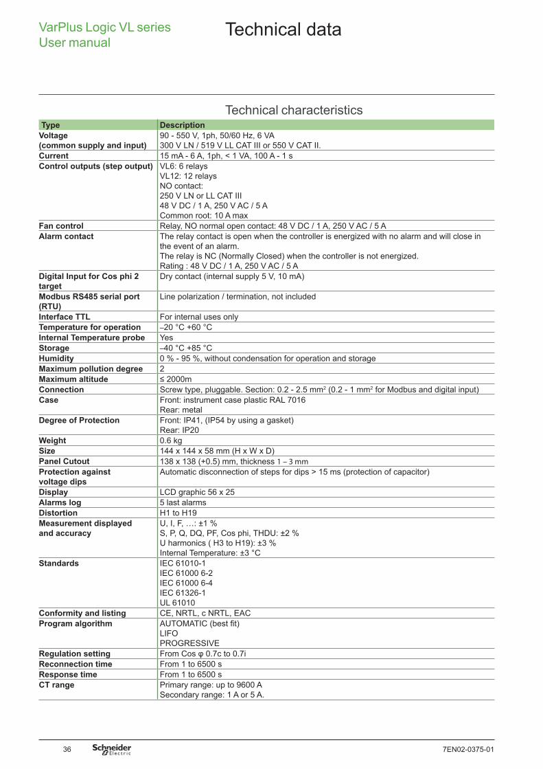
36 7EN02-0375-01
VarPlus Logic VL series User manual
Technical data
Technical characteristicsType Description
Voltage (common supply and input)
90 - 550 V, 1ph, 50/60 Hz, 6 VA300 V LN / 519 V LL CAT III or 550 V CAT II.
Current 15 mA - 6 A, 1ph, < 1 VA, 100 A - 1 sControl outputs (step output) VL6: 6 relays
VL12: 12 relays NO contact: 250 V LN or LL CAT III48 V DC / 1 A, 250 V AC / 5 A Common root: 10 A max
Fan control Relay, NO normal open contact: 48 V DC / 1 A, 250 V AC / 5 AAlarm contact The relay contact is open when the controller is energized with no alarm and will close in
the event of an alarm.The relay is NC (Normally Closed) when the controller is not energized.Rating : 48 V DC / 1 A, 250 V AC / 5 A
Digital Input for Cos phi 2 target
Dry contact (internal supply 5 V, 10 mA)
Modbus RS485 serial port (RTU)
Line polarization / termination, not included
Interface TTL For internal uses onlyTemperature for operation –20 °C +60 °CInternal Temperature probe YesStorage –40 °C +85 °CHumidity 0 % - 95 %, without condensation for operation and storageMaximum pollution degree 2Maximum altitude ≤ 2000mConnection Screw type, pluggable. Section: 0.2 - 2.5 mm2 (0.2 - 1 mm2 for Modbus and digital input)Case Front: instrument case plastic RAL 7016
Rear: metalDegree of Protection Front: IP41, (IP54 by using a gasket)
Rear: IP20Weight 0.6 kgSize 144 x 144 x 58 mm (H x W x D)Panel Cutout 138 x 138 (+0.5) mm, thickness 1 – 3 mmProtection against voltage dips
Automatic disconnection of steps for dips > 15 ms (protection of capacitor)
Display LCD graphic 56 x 25Alarms log 5 last alarmsDistortion H1 to H19Measurement displayed and accuracy
U, I, F, …: ±1 % S, P, Q, DQ, PF, Cos phi, THDU: ±2 % U harmonics ( H3 to H19): ±3 %Internal Temperature: ±3 °C
Standards IEC 61010-1IEC 61000 6-2IEC 61000 6-4IEC 61326-1UL 61010
Conformity and listing CE, NRTL, c NRTL, EACProgram algorithm AUTOMATIC (best fit)
LIFOPROGRESSIVE
Regulation setting From Cos φ 0.7c to 0.7iReconnection time From 1 to 6500 s Response time From 1 to 6500 sCT range Primary range: up to 9600 A
Secondary range: 1 A or 5 A.
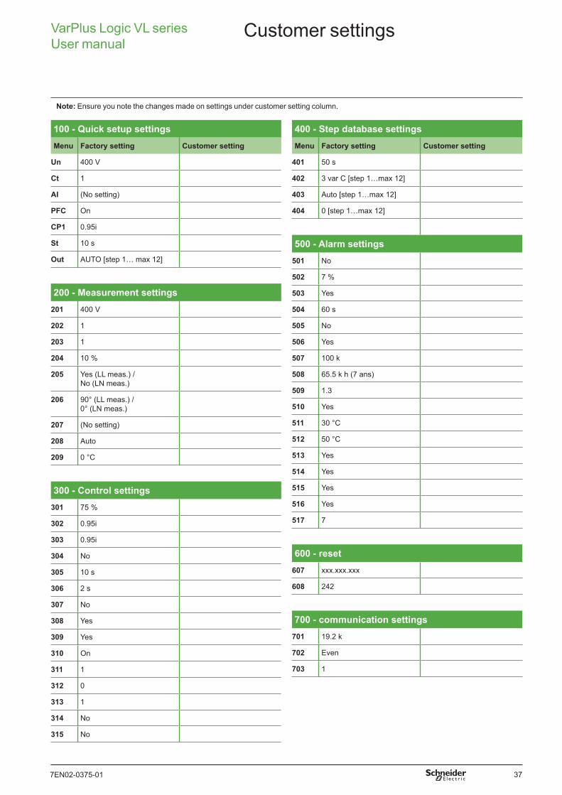
377EN02-0375-01
VarPlus Logic VL series User manual
100 - Quick setup settingsMenu Factory setting Customer setting
Un 400 V
Ct 1
AI (No setting)
PFC On
CP1 0.95i
St 10 s
Out AUTO [step 1… max 12]
200 - Measurement settings201 400 V
202 1
203 1
204 10 %
205 Yes (LL meas.) / No (LN meas.)
206 90° (LL meas.) / 0° (LN meas.)
207 (No setting)
208 Auto
209 0 °C
300 - Control settings301 75 %
302 0.95i
303 0.95i
304 No
305 10 s
306 2 s
307 No
308 Yes
309 Yes
310 On
311 1
312 0
313 1
314 No
315 No
400 - Step database settingsMenu Factory setting Customer setting
401 50 s
402 3 var C [step 1…max 12]
403 Auto [step 1…max 12]
404 0 [step 1…max 12]
500 - Alarm settings501 No
502 7 %
503 Yes
504 60 s
505 No
506 Yes
507 100 k
508 65.5 k h (7 ans)
509 1.3
510 Yes
511 30 °C
512 50 °C
513 Yes
514 Yes
515 Yes
516 Yes
517 7
600 - reset607 xxx.xxx.xxx
608 242
700 - communication settings701 19.2 k
702 Even
703 1
Customer settings
Note: Ensure you note the changes made on settings under customer setting column.

38 7EN02-0375-01
VarPlus Logic VL series User manual
Notes

397EN02-0375-01
VarPlus Logic VL series User manual
Notes

7EN02-0375-01
Schneider Electric35, rue Joseph Monier92500 Rueil Malmaison - Francewww.schneider-electric.com© 2015 Schneider Electric. All Rights Reserved.
Schneider Electric is the trademark or registered trademark of Schneider Electric in France, the USA and other countries. Other trademarks used are the property of their respective owners.