los alamos - welcome to newmexico.gov
TRANSCRIPT

i
Los Alamos NATIONAL LABORATORY
- --E5T 194 3 -- shy
Environmental Programs Natio uclear Security Administration L~ mos Si te Office MS A316
ron mental Restoration Program Los Alamos New Mexico 87544 (505) 667-4255FAX (505) 606-2132
- - 0 ~l PJI 34 I II Date March 31 2009 Ref er To EP2009-0168
Mr Lawrence E Starfield Acting Regional Administrator Environmental Protection Agency Region 6 1445 Ross A venue Suite 1200 Dallas TX 75202-2733
Subject Application for Risk-Based Disposal Approval for the Septic Tank Area at Solid Waste Management Unit 21-024(c)
Dear Mr Starfield
Enclosed for your review is the Los Alamos National Laboratorys (the Laboratorys) application for implementing a risk-based methodology for sampling cleanup and disposal of polychlorinated biphenyl (PCB) remediation waste as described by 40 Code of Federal Regulations (CFR) sect76161(c) for the septic tank area at Solid Waste Management Unit (SWMU) 2l-024(c) As discussed with Mr Richard Mayer of your staff during his February 11 2009 site visit contamination under the septic tank will be remediated to 1 part per million (ppm) to a depth of 10 ft below ground surface (bgs) However current data show total PCBs at one location below the septic tank are approximately 4 ppm at 15 ft bgs and the concentrations at this location are not decreasing with depth In a subsequent telephone conversation on February 18 2009 Mr Mayer requested that the Laboratory submit a risk-based application to provide the US Environmental Protection Agency (EPA) with the information necessary to review and approve the remediation activities under the former septic tank The attached document fulfills this request
PCB remediation will also occur in the nonseptic tank portions of SWMU 21-024(c) and collocated Consolidated Unit 21-003-99 These locations will be remediated to 1 ppm of PCB As requested by EPA the Laboratory will submit a separate notice of self-implementation under the provisions of 40 CFR sect76161 (a)(3 )(i) for these portions of Consolidated Unit 21-003-99 and SWMU 2l-024(c)
If you have any questions please contact Mark Thacker at (505) 699-1963 (mthackerlanlgov) or Woody Woodworth at (505) 665-5820 (lwoodworthdoealgov)
Sincerely Sincerely -shy-
M~~~~GT~~4sociate Director ~~J1tor shy
Environmental Programs Environmental Operations YJ(j Los Alamos National Laboratory Los Alamos Site Office --
An amptudl Opportun i1Y Employer Opermed by Los Alamos Nati onal Secunt y LLC fer lI1 e Natiunal Nucic3 r Sec ur ity Ad min is tration of the U S Depilil meni of -nergy
Lawrenc_e E Starfield 2 March 312009 EP2009-0168
MGIDGIACMTIRBsm
Enclosures Two hard copies with electronic files (1) Application for Risk-Based Disposal Approval for the Septic Tank Area
at Solid Waste Management Unit 21-024(c) (LA-UR-09-1668)
Cy (wenc) Rich Mayer EPA Dallas TX Lou Roberts EPA Dallas TX Kathryn Roberts NMED-HWB Santa Fe NM David Cobrain NMED-HWB Santa Fe NM Max Baker Los Alamos County Los Alamos NM Woody Woodworth DOE-LASO MS A316 Mark Thacker EP-TA-21 MS C349 RPF MS M707 (with two CDs) Public Reading Room MS M992
Cy (Letter and CD only) Laurie King EPA Region 6 Dallas TX Steve Yanicak NMED-OB White Rock NM Emily Day Weston Solutions Los Alamos NM Roy Bohn EP-TA-21 MS C349 Ann Sherrard ENV-RCRA MS K490 Albert Dye ENV-RCRA MS K490 Kristine Smeltz EP-WES MS M992 EP-TA-21 File MS C349
Cy (wo enc) Tom Skibitski NMED-OB Santa Fe NM Keyana DeAguero DOE-LASO (date-stamped letter emailed) Richard S Watkins ADESHQ MS K491 Michael 1 Graham ADEP MS M991 Alison M Dorries EP-WES MS M992 Allan Chaloupka EP-TA-21 MS C349 IRM-RMMSO MS AlSO (date-stamped letter emailed)
An Equal Opportunity Employer I Operaled by Los Alamos National Security LLC for lhe Noti onal Nuclear Security Adminislration of the US Department of Energ y
Application for Risk-Based Disposal Approval for the Septic Tank Area at Solid Waste Management Unit 21-024(c)
Background
Los Alamos National Laboratory (LANL or the Laboratory) Technical Area 21 (TA-21) Closure Project under the Environmental Programs (EP) Directorate is participating in a national effort by the US Department of Energy (DOE) to clean up sites and facilities formerly involved in weapons research and development The sites under investigation and proposed for remediation are designated as solid waste management units (SWMUs) or areas of concern (AOCs) Individual SWMUs and AOCs may be grouped into consolidated units as a result of spatial proximity or function
At TA-21 SWMU 21-024(c) is an inactive septic system installed in the late 1940s (LANL 2004087461 NMED 2005089314) that routed sewage from buildings 21-054 and 21 -061 through a septic tank (structure 21-056) to an outfall and eventually over the mesa top into Los Alamos Canyon Its use was discontinued after 1966 when a wastewater treatment plant was constructed at the east end of T A-21 (LANL 1991 007529 p 15-34) The suspected sources of polychlorinated biphenyl (PCB) contamination in the septic system are spills from the use of PCB-contaminated oil and from the PCB container storage at building 21-061
In 1988 initial contaminant information for SWMU 21-024(c) was obtained from samples collected as part of Environmental Restoration Project reconnaissance sampling effort (LANL 1991 007529) In 1992 and 1993 Resource Conservation and Recovery Act (RCRA) facility investigation (RFI) activities included collecting outfall soil samples (LANL 1994 031591 p 8-18-8-24) The following year RFI activities included drilling a 20-ft borehole in the vicinity of the reinforced concrete septic tank (structure 21-56) (LANL 1995 052350 pp 7-2-7-3) More recently in 2006 the septic tank and associated piping and overlying so il were excavated and removed and the site was further characterized by the collection of additional subsurface samples (LANL 2008 102760) The excavation area was backfilled with clean soil However the extent of PCB contamination is not currently defined under the former septic tank
The Laboratory plans to remove an estimated 20 yd 3 of PCB-contaminated soils from under the former septic tank to 10ft below ground surface (bgs) The total depth of PCB contamination under the septic tank is not known therefore this area is not planned to be remediated to less than 1 part per million (ppm) total PCBs The contamination remaining under the former septic tank deeper than 10ft bgs will be addressed in a risk assessment that will be performed after site remediation is complete The remainder of SMWU 21-024(c) and collocated Consolidated Unit 21-003-99 are addressed in a separate selfshyimplementation notice filed on the same date as this application (LANL 2009 105182) Figures 1 and 2 show the locations of the SWMU addressed in this application
Purpose
The purpose of this risk-based disposal approval application is to provide the US Environmental Protection Agency (EPA) with the information necessary to review and approve the proposed remediation activities at SWMU 21-024(c) under the Toxic Substances and Control Act (40 Code of Federal Regulations [CFR] 76161 [c]) This application also provides the information required by 40 CFR sect761 61 (a)(3)(i) to allow the Laboratory to manage the waste generated from the cleanup as PCB remediation waste This application is organized according to the requirements in 40 CFR sect761 61(a)(3)( i)
LA-UR-09-1668 March 2009 EP2009-0168
Corrective actions at the Laboratory are subject to the March 1 2005 Compliance Order on Consent (the Consent Order) issued pursuant to the New Mexico Hazardous Waste Act New Mexico Statutes Annotated (NMSA) 1978 sect 74-4-10 and the New Mexico Solid Waste Act NMSA 1978 sect 74-9-36(0) Therefore cleanup activities at SWMU 21-024(c) will be conducted as part of RCRA corrective action activities Section VIIIB1a of the Consent Order establishes a default concentration of 1 ppm or a riskshybased PCB cleanup level established through performing a risk assessment in accordance with the New Mexico Environment Departments (NMEDs) Risk-Based Remediation of Polychlorinated Biphenyls at RCRA Corrective Action Sites (NMED 2000 068980) The soil at the removed septic tank location at SWMU 21-024(c) will be excavated to a maximum of 10ft bgs as described in the part 0 of this application A risk assessment will then be performed and submitted to NMED The risk assessment will demonstrate that cleanup levels will not pose an unreasonable risk of injury to health or the environment In addition land-use restrictions will be formulated as needed
(A) The nature of contamination including kinds of materials contaminated
Based on historical information the septic tank at SWMU 21-024(c) was contaminated from PCB fluid storage and use at the buildings connected to the septic system Specifically piping the septic tank and soil removed from the site were contaminated with PCBs PCB-contaminated soil is still present under the location of the removed septic tank The topography of the site slopes from north to south and is covered with vegetation The site drains toward the outfall along the south side of the site (Figure 2) The outfall is being addressed in a separate self-implementation notification filed on the same date as this application (LANL2009105182)
(B) A summary of the procedures used to sample contaminated and adjacent areas and a table or cleanup site map showing PCB concentrations measured in all pre-cleanup characterization samples The summary must include sample collection and analysis dates
This section summarizes the field methods used to collect characterization samples at SWMU 21-024(c) during the 2006 field season All activities were conducted in accordance with the most current versions of applicable standard operating procedures (SOPs) listed below (available at httpwwwlanl govenvironmentlcleanupqashtml)
bull EP-ERSS-SOP-5022 Characterization and Management of Environmental Restoration (ER) Project Waste
bull EP-ERSS-SOP-5028 Coordinating and Evaluating Geodetic Surveys
bull EP-ERSS-SOP-5056 Sample Containers and Preservation
bull EP-ERSS-SOP-5057 Handling Packaging and Transporting Field Samples
bull EP-ERSS-SOP-5058 Sample Control and Field Documentation
bull EP-ERSS-SOP-5059 Field Quality Control Samples
bull EP-ERSS-SOP-5061 Field Decontamination of Equipment
bull SOP-0609 Spade and Scoop Method for Collection of Soil Samples
bull SOP-0610 Hand Auger and Thin-Wall Tube Sampler
bull SOP-0624 Sample Collection from Split-Spoon Samplers and Shelby Tube Samplers
bull SOP-1014 Performing and Documenting Gross Gamma Radiation Scoping Surveys
bull SOP-1201 Field Logging Handling and Documentation of Borehole Materials
LA-UR-09-1668 2 March 2009 EP2009-0 168
Table 1 summarizes the field methods used Existing PCB precleanup characterization data at the former septic tank location are presented in Tables 2 and 3 and are shown in Figure 3
Exploratory Drilling
Cuttings and core were field screened for radioactivity and organic vapors and the core was visually inspected and lithologically logged following SOP-1201 Field Logging Handling and Documentation of Borehole Materials A detailed lithologic log was completed for each boring by a qualified geologist and classified in accordance with Unified Soil Classification System American Society for Testing and Materials 02487 and 02488 or American Geological Institute Methods for Soil and Rock Classification
All drilling equipment was dry-decontaminated after use at each borehole Rinsate blanks on drilling equipment were collected at a frequency of 1 per every 10 analytical samples collected
All drill cuttings generated during sampling activities were placed in appropriate waste containers (rolloff bins or 55-gal drums) and staged in a less-than-90-d waste storage area Waste remained on-site pending receipt of the results of waste characterization which was based on analytical results from core samples augmented by direct sampling if necessary
Surface and Subsurface Sampling
Samples were collected from 00 to 05 ft using the spade-and-scoop method in accordance with SOP-0609 Spade and Scoop Method for Collection of Soil Samples The samples were collected using stainless-steel shovels or spoons and homogenized in stainless-steel bowls Samples were collected at depths of less than 15 ft bgs using the hand-auger method in accordance with SOP-061 0 Hand Auger and Thin-Wall Tube Sampler The material was placed in stainless-steel bowls and handled in the same manner as surface soil samples Samples at the bottom or at the entire length of a borehole were collected using the split-spoon core-barrel method in accordance with SOP-0624 Sample Collection from Split-Spoon Samplers and Shelby Tube Samplers The samples were collected using a cylindrical barrel split lengthwise which enabled separation of the two halves to expose the core sample
The samples were transferred to sterile sample collection jars or bags for transport to the Laboratorys Sample Management Office (SMO)
Quality AssuranceQuality Control Samples
Quality assurancequality control (QNQC) samples for soil and tuff (Qbt 3) were collected in accordance with EP-ERSS-SOP-5059 Field Quality Control Samples Field duplicate samples were collected at a frequency of at least 1 duplicate sample for every 10 samples (10) Field rinsate samples were collected from sampling equipment at a frequency of at least 1 rinsate sample for every 10 samples Field trip blanks also were collected at a frequency of 1 per 10 samples where samples were collected for analysis of volatile organic compounds (VOCs)
Sample Documentation and Handling
Field personnel completed a sample collection log (SCL) and associated chain-of-custody (COC) form for each sample Sample containers were sealed with signed COC seals and placed in coolers at approximately 4degC The samples were packaged handled and shipped in accordance with EP-ERSS-SOP-5057 Handling Packaging and Transporting Field Samples and EP-ERSS-SOP-5056 Sample Containers and Preservation
LA-UR-09-1668 3 March 2009 EP2009-0168
Samples were transported to the SMa in sealed coolers The SMa personnel reviewed and approved the SCLs and COC forms before taking custody of the samples Samples were subsequently shipped to an analytical laboratory
Decontamination of Sampling Equipment
All sampling equipment that came (or could have come) in contact with sampling material was decontaminated immediately before each sample was collected to avoid cross-contamination of samples Dry decontamination (brushing off debris with a brush) was first used to minimize liquid waste Wet decontamination (spraying the equipment with Alconox and deionized water and wiping clean with paper towels) was subsequently used Decontamination activities including collection of rinsate blank samples were performed in accordance with EP-ERSS-SOP-5061 Field Decontamination of Equipment and EP-ERSS-SOP-5059 Field Quality Control Samples
Geodetic Surveying
Geodetic surveys of all sampled locations were performed using a Trimble R8 (integrated receiver radio and antenna) and a permanent base station This real-time kinematic (RTK) global positioning system (GPS) is referenced from published and monumented external Laboratory survey control points in the vicinity All borehole and sampling locations were surveyed according to EP-ERSS-SOP-5028 Coordinating and Evaluating Geodetic Surveys Horizontal accuracy of the monumented control points is within plusmn05 ft The RTK GPS instrument referenced from Laboratory control points is accurate within plusmn05 ft
(C) The location and extent of the identified contaminated areas including topographic maps with sample collection site cross referenced to a sample identification numbers in the data summary from paragraph (a)(3)(i)(b)
Existing PCB characterization data at the septic tank area are presented in Tables 2 and 3 and are shown in Figure 3
Figure 3 presents a cross-section of the former septic tank area from north to south with total PCB concentrations represented in various colors Vertical extent has not been defined under the former septic tank location PCB concentrations increase with depth at location 21-25748 Specifically total PCB concentrations increase from 298 mgkg at a depth of 4 0 to 50 ft bgs to a concentration of 4 14 mgkg at a depth of 14 to 15 ft bgs Before site cleanup activities are conducted a sample will be collected 5 ft deeper than the deepest sample previously collected beneath the location of the former septic tank to establish the extent of PCB contamination additional samples will be collected in 5-ft increments until a decreasing trend is found (Figure 3) The additional sampling is described in part D of this application
(D) A cleanup plan for the site including schedule disposal technology and approach This plan should contain options and contingencies to be used if unanticipated higher concentrations or wider distributions of PCB remediation waste are found or other obstacles force changes in the cleanup approach
Schedule
The preexcavation PCB sampling and site remediation activities are scheduled to begin once EPA approves this application The preexcavation sampling and receipt of analytical results are anticipated to
LA-UR-09-1668 4 March 2009 EP2009-0168
take approximately 2 mo The evaluation of the data and soil removal will be conducted concurrently with sampling efforts and are expected to take approximately 3 mo Site restoration and a summary report are expected to take approximately 2 additional months to complete Based on these estimates the project is expected to be completed approximately 5 mo after EPA approves this application
Disposal Technology
Wastes will consist of PCB-contaminated material that may also contain low-level radionuclide contamination Wastes will be segregated based on characterization data Materials containing greater than or equal to 50 ppm total PCBs (not expected for this cleanup activity) will be separated from those containing less than 50 ppm The requirements of 40 CFR sect76161 (a)(5)(ii) and (a)(5)(v)(A) are summarized below
bull Bulk PCB-remediation wastes with a PCB concentration of less than 50 ppm will be disposed of at an authorized nonmunicipal nonhazardous waste facility an authorized hazardous waste landfill or an authorized PCB landfill The Laboratory does not plan to dispose of this waste in a facility licensed or registered to manage municipal solid waste although it is allowed by 40 CFR sect761 61 (a)(5)(v)(A)
bull Bulk PCB remediation wastes with a PCB concentration of greater than or equal to 50 ppm and less than 500 ppm will be disposed of in an authorized hazardous waste facility or in an authorized EPA-approved PCB disposal facility
Interim storage of the wastes will be at an area of contamination near the areas to be remed iated and managed using best management practices in accordance with 40 CFR sect76165(c)(9) Approval of the area of contamination designation from NMED will be obtained before any wastes are stored at the area of contamination
Approach
A drill rig will be used to collect one sample beneath the area of the removed septic tank for PCB analysis to fully define the extent of PCB site contamination before excavation begins (Table 4) The proposed preexcavation sampling location is shown in Figure 4 The sample will be collected from the 19- to 20-ft depth bgs using the same methods as described in part B of this application and analyzed for PCBs If the results indicate that PCB concentrations are not decreasing with depth (ie are not less than 4 ppm) additional samples will be collected from this location at 5-ft intervals until extent is defined
The proposed excavation area is shown in Figure 4 Total PCBs were previously detected at approximately 4 ppm at 15 ft bgs This area will be excavated to a total of 10ft bgs based on NMED human health risk scenarios (NMED 2006092513) After site remediation a risk assessment will be performed to demonstrate that cleanup levels will not pose an unreasonable risk of injury to health or the environment Land-use restrictions will be formulated as needed to limit exposures
One postremediation confirmatory sample will be collected from the center of the base of the excavation area to determine the level of total PCBs remaining at depth (Table 4)
After confirmatory sampling and cleanup are completed the site will be backfilled with clean soil regraded and seeded
LA-UR-09-1668 5 March 2009 EP2009-0168
(E) A written certification signed by the owner of the property where the cleanup site is located and the party conducting the cleanup This certification must state that the sampling plans sample collection procedures sample preparation procedures extraction procedures and instrumentalchemical analysis procedures used to assess or characterize the PCB contamination are on file at the location designated in the certificate
The written certification and required signatures are on page 7 of this application
LA-UR-09-1668 6 March 2009 EP2009-0 168
CERTIFICATION STATEMENT OF AUTHORIZATION
LOS ALAMOS NATIONAL LABORATORY
Application for Risk-Based Disposal Approval for the Septic Tank Area at Solid Waste Management Unit 21-024(c)
I certify under penalty of law that the information presented within this notice (including the attachments) was prepared under my direction or supervision in accordance with a system designed to assure that qualified personnel properly gathered and evaluated the information submitted Based on my inquiry of the person or persons who manage the system or those persons directly responsible for gathering the information the information submitted is to the best of my knowledge and belief true accurate and complete I am aware that there are significant penalties for submitting false information including the possibility of fine and imprisonment for knowing violation
Additionally the sampling plans sample collection procedures sample preparation procedures extraction procedures and instrumentalchemical analysis procedures used to assess or characterize the polychlorinated biphenyl contamination at the cleanup site are on file for US Environmental Protection Agency inspection These documents and procedures arewill be available at the Los Alamos National Laboratorys Environmental Programs Records Processing Facility
kUvJ~~G~ ichael J Grah Ass iate Director Date
Environmental Programs Los Alamos National Laboratory
avid Gregory Project Directo Datel f
Department of Energy Los Alamos Site Office
LA-UR-09-1668 7 March 2009 EP2009-0 168
REFERENCES
LANL (Los Alamos National Laboratory) May 1991 TA-21 Operable Unit RFI Work Plan for Environmental Restoration Vol II (Chapters 14 to 16) Los Alamos National Laboratory document LA-UR-91-962 Los Alamos New Mexico (LANL 1991007529)
LANL (Los Alamos National Laboratory) February 28 1994 Phase Report 1C TA-21 Operable Unit RCRA Facility Investigation Outfalls Investigation Los Alamos National Laboratory document LA-UR-94-228 Los Alamos New Mexico (LANL 1994 031591)
LANL (Los Alamos National Laboratory) January 1995 Phase Report Addendum 1 Band 1 C Operable Unit 1106 RCRA Facility Investigation Los Alamos National Laboratory document LA-UR-94-4360 Los Alamos New Mexico (LANL 1995 052350)
LANL (Los Alamos National Laboratory) August 2004 Investigation Work Plan for Delta Prime Site Aggregate Area at Technical Area 21 Los Alamos National Laboratory document LA-UR-04-5009 Los Alamos New Mexico (LANL 2004 087461)
LANL (Los Alamos National Laboratory) March 2008 Delta Prime Site Aggregate Area Investigation Report Revision 1 Los Alamos National Laboratory document LA-UR-08-1834 Los Alamos New Mexico (LANL 2008 102760)
LANL (Los Alamos National Laboratory) March 2009 Notice of Self-Implementation of On-Site Cleanup and Disposal of Polychlorinated Biphenyl Remediation Waste for Consolidated Unit 21-003-99 and Solid Waste Management Unit 21-024(c) Los Alamos National Laboratory document LA-UR-09-1667 Los Alamos New Mexico (LAIIL 2009105182)
NMED (New Mexico Environment Department) March 22000 Risk-Based Remediation of Polychlorinated Biphenyls at RCRA Corrective Action Sites position paper Hazardous and Radioactive Materials Bureau Santa Fe New Mexico (NMED 2000 068980)
NMED (New Mexico Environment Department) April 13 2005 Approval with Modifications for the Investigation Work Plan for Delta Prime Site Aggregate Area at Technical Area 21 New Mexico Environment Department letter to D Gregory (DOE LASO) and GP Nanos (LANL Director) from JP Bearzi (NMED-HWB) Santa Fe New Mexico (NMED 2005089314)
NMED (New Mexico Environment Department) June 2006 Technical Background Document for Development of Soil Screening Levels Revision 40 Volume 1 Tier 1 Soil Screening Guidance Technical Background Document New Mexico Environment Department Hazardous Waste Bureau and Ground Water Quality Bureau Voluntary Remediation Program Santa Fe New Mexico (NMED 2006 092513)
LA-UR-09-1668 8 March 2009 EP2009-0168
15
r- I t __
I
- _~_ l 36
--
49 68
39
Laboratory boundary
I _ __ Technical area boundary
_ TA-21
-N Primary paved road
San IIdefonso Pueblo Lands
Secondary paved road
Bandelier Na60nal
Monument
White Rock
n
2500 5000 10000
Feel
Figure 1 Consolidated Unit 21-003-99 and SWMU 21-024c) within TA-21
LA-UR-09-1668 9 March 2009 EP2009-0168
qJS ~ oC00(0 0 0(0 0) 0gt0)
0) 0gt
o
1633100 1633200
~ ~ ~--l_~___r_ - 1
I 21-0 9 t I I
t - shy ~--Csf j
1633300 1633400
~
1633500
- l --shy
1633600
1
--------------shy------------------------shy
8 r-shy
sect r-shyr-shy Sr
~ sect r-shy
~ ~
21-003-99
8 Ol
r-shyr-shy~
8 Ol M r-shyr-shy
~ 1
h middotmiddot middotmiddotmiddothhh N
w+ O~JO o so s
co Slate - CoorjJL ~ Can1 ze p OO2 NAD 113 us swy Hlel
~I7( DhIllFrarj 10 ~200e
middotmiddot middot middot 1 Mlp ~OFFol -1 1 1 ~oe
1633100
r
_ -1- 1633200 1633300 1633400
D 21003-99
D 21o24(c)
D Structure
tJ Former structure
MDA Aspha lt pad
Sampl ing location
Communication
V Electric
~ Gas
V Sewer
Steam
V Water
1-1633500
-Igtf V
~
Security fence
Paved road
Unpaved road
Former piping
100 and 20 It contour
10 and 2 It contour
1633600
8 OJ M r-shyr-shy
~ Cir
o ~
o Figure 2 Location of SWMU 21-024(c) (0
~sNoe00 lt0 0 0lt0 0) coO)
0) CO
7100
7050
7000
6950
5900
1774200 1774100 1 7 74000 1773900 1773800 1773700 sN SWMU 21-024(c) Septic Tank Area Cross Section NorthSouth Cross Section
40 - 50 cJ 30- 40 _ 20-30 _ 10-20 _ 0-10 Total PCB concenlrations in mgkg
Removed Septic Tank 21-056- Cartography Dave Frank March 9 2009
~
Dale
2125755
Plan View
N
A
- --7120
tll Ci J- N s N 0 0 lt0 Figure 3 Concentrations of total PCBs and cross-section of the former septic tank area SWMU 21-024(c)
1633370 tJs 1633290 1633300 1633310NoC0tJ (c0 O(C 0gt coOgt
0gt CO o
~ M r-shy~
o
~ r-shy~
~
~ ~
I)
o g M r-shy~
o
g 2 ~
~
-_ ~
shy
D SWMU 2Hgt24(c)
D Consolidated Unit 21-003-99
--1___ Excavation area
[==J Former structure
Sampling location wrth total PCBsgt 1 mgkg
o Deeper pre-excavation sampling location
Former pipeline
100 and 20-11 contour
o 10 20 A Feet ~
NeN Mexko StoIUt Plane CoorOlna1a Sy05lBm ~ CenlrJi Zone (3002)
Nonh American OatLm 1983 US Survey Feel
- -shy - -shy - shy _-- - ----shy --_ shy
This map WBIi created lor work processes social8d wtlh the Aamp$ociale Directorate lor EnVHonmenlai Pl09rams VItIste and EnVIronmental Servces (AOEP-WES) All other uses for hIs map ~hOuk1 be conrirmed WIth LANl ADEP-WES staff ~
r N o o Figure 4 (C Proposed PCB sampling and excavation area at SWMU 21-024(c)
1633320 1633330 1633340 1633350 1633360
Map created by DsoIe Frank Marcil 3 2009 Map number DFw 02()J03IOQ
Table 1 Summary of Field Methods
Method Summary
SOP-0609 Spade and Scoop This method was used for collection of shallow (approximately 0- to 05-ft) soil Method for Collection of Soil samples The spade-and-scoop method involved digging a hole to the desired Samples depth as prescribed in the sampling and analysis plan and collecting a
discrete grab sample Typically the sample was placed in a clean stainless-steel bowl for transfer to various sample containers
SOP-0610 Hand Auger and This method was used for sampling soil or Obt 3 at depths of less than 15 ft Thin-Wall Tube Sampler bgs This method involved hand-turning a stainless-steel bucket auger (typically
3- to 4-in-inside diameter [10]) with an attached thin-wall tube sampler creating a vertical hole that could be advanced to the desired sample depth When the desired depth was reached the auger was decontaminated before advancing the hole through the sample depth The sample material was transferred from the bucket auger to a stainless-steel sampling bowl before the various required sampled containers were filled
SOP-0624 Sample Collection from Split-Spoon Samplers and Shelby Tube Samplers
The split-spoon core barrel is a cylindrical barrel split lengthwise so that the two halves can be separated to expose the core sample The stainless-steel core barrel (3-in-ID 5 ft long) is pushed directly into the subsurface media using a hollow-stem auger drilling rig A continuous length of core was screened for radioactivity and organic vapors and described in a geologic log If located within a targeted sample interval a portion of the core was collected for fixed laboratory analysis
SOP-1201 Field Logging Handling and Documentation of Borehole Materials
Upon reaching the surface core barrels were immediately opened for field screening logging and sampling Once the core material was logged selected samples were taken from discrete intervals of the core All borehole material not sampled was disposed of as investigation-derived waste (lOW)
EP-ERSS-SOP-5057 Handling Packaging and Transporting Field Samples
Field team members sealed and labeled samples before packing to ensure the sample containers and the containers used for transport were free of external contamination All environmental samples were collected preserved packaged and transported to the SMO under COC The SMO arranged for the shipping of the samples to analytical laboratories Any levels of radioactivity (i e action-level or limited quantity ranges) were documented on sample collection logs submitted to the SMO
EP-ERSS-SOP-5058 Sample The SMO generated standard forms that documented the collection screening Control and Field Documentation and transport of samples These forms included sample collection logs COC
forms SCLs and custody seals Collection logs were completed at the time of sample collection and were signed by the sampler and a reviewer who verified the logs for completeness and accuracy Corresponding labels were generated and applied to each sample container and custody seals were placed around container lickgt or openings COC forms were completed and signed to verify that the samples were not left unattended
LA-UR-09-1668 13 March 2009 EP2009-0168
Table 1 (continued)
Method Summary
EP-ERSS-SOP-5059 Field Field Duplicates Collected at the same time as a regular sample at a frequency Quality Control Samples of 10 and submitted for the same analyses
Equipment Rinsate Blanks Collected by rinsing sampling eqUipment with deionized water at a frequency of 10 The water was collected in a sample container and submitted for laboratory analyses
Trip Blanks Required for all field events that include the collection of samples for VOC analyses Trip blank containers certified clean were kept with the other sample containers during the sampling process and submitted for laboratory analyses
Manufacturers Instructions for Soil and Qbt 3 samples were field screened for headspace total VOCs by PID Screening for Total VOCs placing a portion of the sample in a resealable plastic sample bag The
container was sealed and gently shaken and then allowed to equilibrate for 5 min The sample was screened by inserting a photoionization detector (PID) probe into the container and recording any detected VOCs
SOP-1014 Performing and Scoping surveys provide limited site-specific information based on direct Documenting Gross Gamma measurements When scoping surveys identify contamination a Radiation Scoping Surveys characterization survey is typically performed by a qualified radiological control
technician (RCT) who has been properly trained in the implementation of survey techniques
A Laboratory RCT conducted radionuclide screening of all samples for alpha beta and gamma emitters Radionuclide screening consisted of a direct frisk survey using an Eberline E-600 rate meter with an SHP 380 probe to measure alphabeta activity Furthermore a smear survey of the sample was conducted and submitted to the Health PhYSics Analytical Laboratory for detection of contamination using a 2929 Ludlum Dual Scaler smear counter with a 43-10 probe to verify nondetectable activity
EP-ERSS-SOP-5022 Characterization and Management of Environmental Restoration (ER) Project Waste
lOW was managed characterized and stored in accordance with an approved waste characterization strategy form that documents site history field activities and the characterization approach for each waste stream managed Waste characterization complied with on-site or off-site waste acceptance criteria as appropriate All stored lOW was marked with appropriate signs and labels Drums containing lOW were stored on pallets The means to store control and transport each potential waste type and the classification of the waste were determined before field operations began A waste storage area was established before waste was generated Each waste container was individually labeled with waste classification item identification and radioactivity (if applicable) immediately after containerization All waste was segregated by classification and compatibility to prevent cross-contamination
EP-ERSS-SOP-5056 Sample Specific requirementsprocesses for sample containers preservation Containers and Preservation techniques and holding times were based on EPA guidance for environmental
sampling preservation and QA Specific requirements for each sample were printed in the sample collection logs the SMO provided (size and type of container preservatives etc) All samples were preserved by placing them in insulated containers with ice to maintain a temperature of 4degC
EP-ERSS-SOP-5028 Geodetic surveys focused on obtaining survey data of acceptable quality to use Coordinating and Evaluating during project investigations The surveys were conducted with a Trimble R8 Geodetic Surveys (integrated receiver radio and antenna) and Laboratory permanent base
station
LA-UR-09-1668 14 March 2009 EP2009-0168
Table 2 Samples Analyzed for PCBs at SWMU 21-024(c)
Sample 10 Method Date
Analyzed Date
Collected Location
ID Depth
(ft) Media PCBs
MD21-07-74337 SW-8468082 04232007 04122007 21-25748 40-50 Obt 3 6904S
MD21-07-74338 SW-8468082 04232007 04122007 21-25748 140-150 Obt 3 6904S
MD21-07-74347 SW-8468082 03012007 02222007 21-25754 20-30 Soil 6739S
MD21-07-74348 SW-8468082 03012007 02222007 21-25754 40-50 Obt 3 6739S
MD21-07-74349 SW-8468082 03012007 02222007 21-25755 20-30 Soil 6739S
MD21-07-74350 SW-8468082 03012007 02222007 21-25755 40-50 Soil 6739S
Alphanumeric = Analysis request number
Table 3 Aroclors and Total PCBs Detected at SWMU 21-024(c)
Sample 10 Location 10 Depth
(ft) Media Aroclor-1254
(mgkg) Aroclor-1260
(mgkg) Total PCBs
(mgkg)
MD21-07-74337 21-25748 40-50 Obt 3 162 136 298
MD21-07-74338 21-25748 140-150 Obt 3 298 116 414
MD21-07-74347 21-25754 20-30 Soil 0889 0941 183
MD21-07-74348 21-25754 40-50 Obt 3 0173 0247 042
MD21-07-74349 21-25755 20-30 Soil 105 121 226
MD21-07-74350 21-25755 40-50 Soil 0598 0784 1382
Table 4 Proposed PCB Sampling at SWMU 21-024(c)
Objective Addressed Location Number
Sample Depth (ft)
Establish vertical extent of PCB contamination at location 21-25748 21-25748 19-20
Conduct confirmation sampling for PCBs 21-25748 Center of excavation area one depth
LA-UR-09-1668 15 March 2009 EP2009-0168

Application for Risk-Based Disposal Approval for the Septic Tank Area at Solid Waste Management Unit 21-024(c)
Background
Los Alamos National Laboratory (LANL or the Laboratory) Technical Area 21 (TA-21) Closure Project under the Environmental Programs (EP) Directorate is participating in a national effort by the US Department of Energy (DOE) to clean up sites and facilities formerly involved in weapons research and development The sites under investigation and proposed for remediation are designated as solid waste management units (SWMUs) or areas of concern (AOCs) Individual SWMUs and AOCs may be grouped into consolidated units as a result of spatial proximity or function
At TA-21 SWMU 21-024(c) is an inactive septic system installed in the late 1940s (LANL 2004087461 NMED 2005089314) that routed sewage from buildings 21-054 and 21 -061 through a septic tank (structure 21-056) to an outfall and eventually over the mesa top into Los Alamos Canyon Its use was discontinued after 1966 when a wastewater treatment plant was constructed at the east end of T A-21 (LANL 1991 007529 p 15-34) The suspected sources of polychlorinated biphenyl (PCB) contamination in the septic system are spills from the use of PCB-contaminated oil and from the PCB container storage at building 21-061
In 1988 initial contaminant information for SWMU 21-024(c) was obtained from samples collected as part of Environmental Restoration Project reconnaissance sampling effort (LANL 1991 007529) In 1992 and 1993 Resource Conservation and Recovery Act (RCRA) facility investigation (RFI) activities included collecting outfall soil samples (LANL 1994 031591 p 8-18-8-24) The following year RFI activities included drilling a 20-ft borehole in the vicinity of the reinforced concrete septic tank (structure 21-56) (LANL 1995 052350 pp 7-2-7-3) More recently in 2006 the septic tank and associated piping and overlying so il were excavated and removed and the site was further characterized by the collection of additional subsurface samples (LANL 2008 102760) The excavation area was backfilled with clean soil However the extent of PCB contamination is not currently defined under the former septic tank
The Laboratory plans to remove an estimated 20 yd 3 of PCB-contaminated soils from under the former septic tank to 10ft below ground surface (bgs) The total depth of PCB contamination under the septic tank is not known therefore this area is not planned to be remediated to less than 1 part per million (ppm) total PCBs The contamination remaining under the former septic tank deeper than 10ft bgs will be addressed in a risk assessment that will be performed after site remediation is complete The remainder of SMWU 21-024(c) and collocated Consolidated Unit 21-003-99 are addressed in a separate selfshyimplementation notice filed on the same date as this application (LANL 2009 105182) Figures 1 and 2 show the locations of the SWMU addressed in this application
Purpose
The purpose of this risk-based disposal approval application is to provide the US Environmental Protection Agency (EPA) with the information necessary to review and approve the proposed remediation activities at SWMU 21-024(c) under the Toxic Substances and Control Act (40 Code of Federal Regulations [CFR] 76161 [c]) This application also provides the information required by 40 CFR sect761 61 (a)(3)(i) to allow the Laboratory to manage the waste generated from the cleanup as PCB remediation waste This application is organized according to the requirements in 40 CFR sect761 61(a)(3)( i)
LA-UR-09-1668 March 2009 EP2009-0168
Corrective actions at the Laboratory are subject to the March 1 2005 Compliance Order on Consent (the Consent Order) issued pursuant to the New Mexico Hazardous Waste Act New Mexico Statutes Annotated (NMSA) 1978 sect 74-4-10 and the New Mexico Solid Waste Act NMSA 1978 sect 74-9-36(0) Therefore cleanup activities at SWMU 21-024(c) will be conducted as part of RCRA corrective action activities Section VIIIB1a of the Consent Order establishes a default concentration of 1 ppm or a riskshybased PCB cleanup level established through performing a risk assessment in accordance with the New Mexico Environment Departments (NMEDs) Risk-Based Remediation of Polychlorinated Biphenyls at RCRA Corrective Action Sites (NMED 2000 068980) The soil at the removed septic tank location at SWMU 21-024(c) will be excavated to a maximum of 10ft bgs as described in the part 0 of this application A risk assessment will then be performed and submitted to NMED The risk assessment will demonstrate that cleanup levels will not pose an unreasonable risk of injury to health or the environment In addition land-use restrictions will be formulated as needed
(A) The nature of contamination including kinds of materials contaminated
Based on historical information the septic tank at SWMU 21-024(c) was contaminated from PCB fluid storage and use at the buildings connected to the septic system Specifically piping the septic tank and soil removed from the site were contaminated with PCBs PCB-contaminated soil is still present under the location of the removed septic tank The topography of the site slopes from north to south and is covered with vegetation The site drains toward the outfall along the south side of the site (Figure 2) The outfall is being addressed in a separate self-implementation notification filed on the same date as this application (LANL2009105182)
(B) A summary of the procedures used to sample contaminated and adjacent areas and a table or cleanup site map showing PCB concentrations measured in all pre-cleanup characterization samples The summary must include sample collection and analysis dates
This section summarizes the field methods used to collect characterization samples at SWMU 21-024(c) during the 2006 field season All activities were conducted in accordance with the most current versions of applicable standard operating procedures (SOPs) listed below (available at httpwwwlanl govenvironmentlcleanupqashtml)
bull EP-ERSS-SOP-5022 Characterization and Management of Environmental Restoration (ER) Project Waste
bull EP-ERSS-SOP-5028 Coordinating and Evaluating Geodetic Surveys
bull EP-ERSS-SOP-5056 Sample Containers and Preservation
bull EP-ERSS-SOP-5057 Handling Packaging and Transporting Field Samples
bull EP-ERSS-SOP-5058 Sample Control and Field Documentation
bull EP-ERSS-SOP-5059 Field Quality Control Samples
bull EP-ERSS-SOP-5061 Field Decontamination of Equipment
bull SOP-0609 Spade and Scoop Method for Collection of Soil Samples
bull SOP-0610 Hand Auger and Thin-Wall Tube Sampler
bull SOP-0624 Sample Collection from Split-Spoon Samplers and Shelby Tube Samplers
bull SOP-1014 Performing and Documenting Gross Gamma Radiation Scoping Surveys
bull SOP-1201 Field Logging Handling and Documentation of Borehole Materials
LA-UR-09-1668 2 March 2009 EP2009-0 168
Table 1 summarizes the field methods used Existing PCB precleanup characterization data at the former septic tank location are presented in Tables 2 and 3 and are shown in Figure 3
Exploratory Drilling
Cuttings and core were field screened for radioactivity and organic vapors and the core was visually inspected and lithologically logged following SOP-1201 Field Logging Handling and Documentation of Borehole Materials A detailed lithologic log was completed for each boring by a qualified geologist and classified in accordance with Unified Soil Classification System American Society for Testing and Materials 02487 and 02488 or American Geological Institute Methods for Soil and Rock Classification
All drilling equipment was dry-decontaminated after use at each borehole Rinsate blanks on drilling equipment were collected at a frequency of 1 per every 10 analytical samples collected
All drill cuttings generated during sampling activities were placed in appropriate waste containers (rolloff bins or 55-gal drums) and staged in a less-than-90-d waste storage area Waste remained on-site pending receipt of the results of waste characterization which was based on analytical results from core samples augmented by direct sampling if necessary
Surface and Subsurface Sampling
Samples were collected from 00 to 05 ft using the spade-and-scoop method in accordance with SOP-0609 Spade and Scoop Method for Collection of Soil Samples The samples were collected using stainless-steel shovels or spoons and homogenized in stainless-steel bowls Samples were collected at depths of less than 15 ft bgs using the hand-auger method in accordance with SOP-061 0 Hand Auger and Thin-Wall Tube Sampler The material was placed in stainless-steel bowls and handled in the same manner as surface soil samples Samples at the bottom or at the entire length of a borehole were collected using the split-spoon core-barrel method in accordance with SOP-0624 Sample Collection from Split-Spoon Samplers and Shelby Tube Samplers The samples were collected using a cylindrical barrel split lengthwise which enabled separation of the two halves to expose the core sample
The samples were transferred to sterile sample collection jars or bags for transport to the Laboratorys Sample Management Office (SMO)
Quality AssuranceQuality Control Samples
Quality assurancequality control (QNQC) samples for soil and tuff (Qbt 3) were collected in accordance with EP-ERSS-SOP-5059 Field Quality Control Samples Field duplicate samples were collected at a frequency of at least 1 duplicate sample for every 10 samples (10) Field rinsate samples were collected from sampling equipment at a frequency of at least 1 rinsate sample for every 10 samples Field trip blanks also were collected at a frequency of 1 per 10 samples where samples were collected for analysis of volatile organic compounds (VOCs)
Sample Documentation and Handling
Field personnel completed a sample collection log (SCL) and associated chain-of-custody (COC) form for each sample Sample containers were sealed with signed COC seals and placed in coolers at approximately 4degC The samples were packaged handled and shipped in accordance with EP-ERSS-SOP-5057 Handling Packaging and Transporting Field Samples and EP-ERSS-SOP-5056 Sample Containers and Preservation
LA-UR-09-1668 3 March 2009 EP2009-0168
Samples were transported to the SMa in sealed coolers The SMa personnel reviewed and approved the SCLs and COC forms before taking custody of the samples Samples were subsequently shipped to an analytical laboratory
Decontamination of Sampling Equipment
All sampling equipment that came (or could have come) in contact with sampling material was decontaminated immediately before each sample was collected to avoid cross-contamination of samples Dry decontamination (brushing off debris with a brush) was first used to minimize liquid waste Wet decontamination (spraying the equipment with Alconox and deionized water and wiping clean with paper towels) was subsequently used Decontamination activities including collection of rinsate blank samples were performed in accordance with EP-ERSS-SOP-5061 Field Decontamination of Equipment and EP-ERSS-SOP-5059 Field Quality Control Samples
Geodetic Surveying
Geodetic surveys of all sampled locations were performed using a Trimble R8 (integrated receiver radio and antenna) and a permanent base station This real-time kinematic (RTK) global positioning system (GPS) is referenced from published and monumented external Laboratory survey control points in the vicinity All borehole and sampling locations were surveyed according to EP-ERSS-SOP-5028 Coordinating and Evaluating Geodetic Surveys Horizontal accuracy of the monumented control points is within plusmn05 ft The RTK GPS instrument referenced from Laboratory control points is accurate within plusmn05 ft
(C) The location and extent of the identified contaminated areas including topographic maps with sample collection site cross referenced to a sample identification numbers in the data summary from paragraph (a)(3)(i)(b)
Existing PCB characterization data at the septic tank area are presented in Tables 2 and 3 and are shown in Figure 3
Figure 3 presents a cross-section of the former septic tank area from north to south with total PCB concentrations represented in various colors Vertical extent has not been defined under the former septic tank location PCB concentrations increase with depth at location 21-25748 Specifically total PCB concentrations increase from 298 mgkg at a depth of 4 0 to 50 ft bgs to a concentration of 4 14 mgkg at a depth of 14 to 15 ft bgs Before site cleanup activities are conducted a sample will be collected 5 ft deeper than the deepest sample previously collected beneath the location of the former septic tank to establish the extent of PCB contamination additional samples will be collected in 5-ft increments until a decreasing trend is found (Figure 3) The additional sampling is described in part D of this application
(D) A cleanup plan for the site including schedule disposal technology and approach This plan should contain options and contingencies to be used if unanticipated higher concentrations or wider distributions of PCB remediation waste are found or other obstacles force changes in the cleanup approach
Schedule
The preexcavation PCB sampling and site remediation activities are scheduled to begin once EPA approves this application The preexcavation sampling and receipt of analytical results are anticipated to
LA-UR-09-1668 4 March 2009 EP2009-0168
take approximately 2 mo The evaluation of the data and soil removal will be conducted concurrently with sampling efforts and are expected to take approximately 3 mo Site restoration and a summary report are expected to take approximately 2 additional months to complete Based on these estimates the project is expected to be completed approximately 5 mo after EPA approves this application
Disposal Technology
Wastes will consist of PCB-contaminated material that may also contain low-level radionuclide contamination Wastes will be segregated based on characterization data Materials containing greater than or equal to 50 ppm total PCBs (not expected for this cleanup activity) will be separated from those containing less than 50 ppm The requirements of 40 CFR sect76161 (a)(5)(ii) and (a)(5)(v)(A) are summarized below
bull Bulk PCB-remediation wastes with a PCB concentration of less than 50 ppm will be disposed of at an authorized nonmunicipal nonhazardous waste facility an authorized hazardous waste landfill or an authorized PCB landfill The Laboratory does not plan to dispose of this waste in a facility licensed or registered to manage municipal solid waste although it is allowed by 40 CFR sect761 61 (a)(5)(v)(A)
bull Bulk PCB remediation wastes with a PCB concentration of greater than or equal to 50 ppm and less than 500 ppm will be disposed of in an authorized hazardous waste facility or in an authorized EPA-approved PCB disposal facility
Interim storage of the wastes will be at an area of contamination near the areas to be remed iated and managed using best management practices in accordance with 40 CFR sect76165(c)(9) Approval of the area of contamination designation from NMED will be obtained before any wastes are stored at the area of contamination
Approach
A drill rig will be used to collect one sample beneath the area of the removed septic tank for PCB analysis to fully define the extent of PCB site contamination before excavation begins (Table 4) The proposed preexcavation sampling location is shown in Figure 4 The sample will be collected from the 19- to 20-ft depth bgs using the same methods as described in part B of this application and analyzed for PCBs If the results indicate that PCB concentrations are not decreasing with depth (ie are not less than 4 ppm) additional samples will be collected from this location at 5-ft intervals until extent is defined
The proposed excavation area is shown in Figure 4 Total PCBs were previously detected at approximately 4 ppm at 15 ft bgs This area will be excavated to a total of 10ft bgs based on NMED human health risk scenarios (NMED 2006092513) After site remediation a risk assessment will be performed to demonstrate that cleanup levels will not pose an unreasonable risk of injury to health or the environment Land-use restrictions will be formulated as needed to limit exposures
One postremediation confirmatory sample will be collected from the center of the base of the excavation area to determine the level of total PCBs remaining at depth (Table 4)
After confirmatory sampling and cleanup are completed the site will be backfilled with clean soil regraded and seeded
LA-UR-09-1668 5 March 2009 EP2009-0168
(E) A written certification signed by the owner of the property where the cleanup site is located and the party conducting the cleanup This certification must state that the sampling plans sample collection procedures sample preparation procedures extraction procedures and instrumentalchemical analysis procedures used to assess or characterize the PCB contamination are on file at the location designated in the certificate
The written certification and required signatures are on page 7 of this application
LA-UR-09-1668 6 March 2009 EP2009-0 168
CERTIFICATION STATEMENT OF AUTHORIZATION
LOS ALAMOS NATIONAL LABORATORY
Application for Risk-Based Disposal Approval for the Septic Tank Area at Solid Waste Management Unit 21-024(c)
I certify under penalty of law that the information presented within this notice (including the attachments) was prepared under my direction or supervision in accordance with a system designed to assure that qualified personnel properly gathered and evaluated the information submitted Based on my inquiry of the person or persons who manage the system or those persons directly responsible for gathering the information the information submitted is to the best of my knowledge and belief true accurate and complete I am aware that there are significant penalties for submitting false information including the possibility of fine and imprisonment for knowing violation
Additionally the sampling plans sample collection procedures sample preparation procedures extraction procedures and instrumentalchemical analysis procedures used to assess or characterize the polychlorinated biphenyl contamination at the cleanup site are on file for US Environmental Protection Agency inspection These documents and procedures arewill be available at the Los Alamos National Laboratorys Environmental Programs Records Processing Facility
kUvJ~~G~ ichael J Grah Ass iate Director Date
Environmental Programs Los Alamos National Laboratory
avid Gregory Project Directo Datel f
Department of Energy Los Alamos Site Office
LA-UR-09-1668 7 March 2009 EP2009-0 168
REFERENCES
LANL (Los Alamos National Laboratory) May 1991 TA-21 Operable Unit RFI Work Plan for Environmental Restoration Vol II (Chapters 14 to 16) Los Alamos National Laboratory document LA-UR-91-962 Los Alamos New Mexico (LANL 1991007529)
LANL (Los Alamos National Laboratory) February 28 1994 Phase Report 1C TA-21 Operable Unit RCRA Facility Investigation Outfalls Investigation Los Alamos National Laboratory document LA-UR-94-228 Los Alamos New Mexico (LANL 1994 031591)
LANL (Los Alamos National Laboratory) January 1995 Phase Report Addendum 1 Band 1 C Operable Unit 1106 RCRA Facility Investigation Los Alamos National Laboratory document LA-UR-94-4360 Los Alamos New Mexico (LANL 1995 052350)
LANL (Los Alamos National Laboratory) August 2004 Investigation Work Plan for Delta Prime Site Aggregate Area at Technical Area 21 Los Alamos National Laboratory document LA-UR-04-5009 Los Alamos New Mexico (LANL 2004 087461)
LANL (Los Alamos National Laboratory) March 2008 Delta Prime Site Aggregate Area Investigation Report Revision 1 Los Alamos National Laboratory document LA-UR-08-1834 Los Alamos New Mexico (LANL 2008 102760)
LANL (Los Alamos National Laboratory) March 2009 Notice of Self-Implementation of On-Site Cleanup and Disposal of Polychlorinated Biphenyl Remediation Waste for Consolidated Unit 21-003-99 and Solid Waste Management Unit 21-024(c) Los Alamos National Laboratory document LA-UR-09-1667 Los Alamos New Mexico (LAIIL 2009105182)
NMED (New Mexico Environment Department) March 22000 Risk-Based Remediation of Polychlorinated Biphenyls at RCRA Corrective Action Sites position paper Hazardous and Radioactive Materials Bureau Santa Fe New Mexico (NMED 2000 068980)
NMED (New Mexico Environment Department) April 13 2005 Approval with Modifications for the Investigation Work Plan for Delta Prime Site Aggregate Area at Technical Area 21 New Mexico Environment Department letter to D Gregory (DOE LASO) and GP Nanos (LANL Director) from JP Bearzi (NMED-HWB) Santa Fe New Mexico (NMED 2005089314)
NMED (New Mexico Environment Department) June 2006 Technical Background Document for Development of Soil Screening Levels Revision 40 Volume 1 Tier 1 Soil Screening Guidance Technical Background Document New Mexico Environment Department Hazardous Waste Bureau and Ground Water Quality Bureau Voluntary Remediation Program Santa Fe New Mexico (NMED 2006 092513)
LA-UR-09-1668 8 March 2009 EP2009-0168
15
r- I t __
I
- _~_ l 36
--
49 68
39
Laboratory boundary
I _ __ Technical area boundary
_ TA-21
-N Primary paved road
San IIdefonso Pueblo Lands
Secondary paved road
Bandelier Na60nal
Monument
White Rock
n
2500 5000 10000
Feel
Figure 1 Consolidated Unit 21-003-99 and SWMU 21-024c) within TA-21
LA-UR-09-1668 9 March 2009 EP2009-0168
qJS ~ oC00(0 0 0(0 0) 0gt0)
0) 0gt
o
1633100 1633200
~ ~ ~--l_~___r_ - 1
I 21-0 9 t I I
t - shy ~--Csf j
1633300 1633400
~
1633500
- l --shy
1633600
1
--------------shy------------------------shy
8 r-shy
sect r-shyr-shy Sr
~ sect r-shy
~ ~
21-003-99
8 Ol
r-shyr-shy~
8 Ol M r-shyr-shy
~ 1
h middotmiddot middotmiddotmiddothhh N
w+ O~JO o so s
co Slate - CoorjJL ~ Can1 ze p OO2 NAD 113 us swy Hlel
~I7( DhIllFrarj 10 ~200e
middotmiddot middot middot 1 Mlp ~OFFol -1 1 1 ~oe
1633100
r
_ -1- 1633200 1633300 1633400
D 21003-99
D 21o24(c)
D Structure
tJ Former structure
MDA Aspha lt pad
Sampl ing location
Communication
V Electric
~ Gas
V Sewer
Steam
V Water
1-1633500
-Igtf V
~
Security fence
Paved road
Unpaved road
Former piping
100 and 20 It contour
10 and 2 It contour
1633600
8 OJ M r-shyr-shy
~ Cir
o ~
o Figure 2 Location of SWMU 21-024(c) (0
~sNoe00 lt0 0 0lt0 0) coO)
0) CO
7100
7050
7000
6950
5900
1774200 1774100 1 7 74000 1773900 1773800 1773700 sN SWMU 21-024(c) Septic Tank Area Cross Section NorthSouth Cross Section
40 - 50 cJ 30- 40 _ 20-30 _ 10-20 _ 0-10 Total PCB concenlrations in mgkg
Removed Septic Tank 21-056- Cartography Dave Frank March 9 2009
~
Dale
2125755
Plan View
N
A
- --7120
tll Ci J- N s N 0 0 lt0 Figure 3 Concentrations of total PCBs and cross-section of the former septic tank area SWMU 21-024(c)
1633370 tJs 1633290 1633300 1633310NoC0tJ (c0 O(C 0gt coOgt
0gt CO o
~ M r-shy~
o
~ r-shy~
~
~ ~
I)
o g M r-shy~
o
g 2 ~
~
-_ ~
shy
D SWMU 2Hgt24(c)
D Consolidated Unit 21-003-99
--1___ Excavation area
[==J Former structure
Sampling location wrth total PCBsgt 1 mgkg
o Deeper pre-excavation sampling location
Former pipeline
100 and 20-11 contour
o 10 20 A Feet ~
NeN Mexko StoIUt Plane CoorOlna1a Sy05lBm ~ CenlrJi Zone (3002)
Nonh American OatLm 1983 US Survey Feel
- -shy - -shy - shy _-- - ----shy --_ shy
This map WBIi created lor work processes social8d wtlh the Aamp$ociale Directorate lor EnVHonmenlai Pl09rams VItIste and EnVIronmental Servces (AOEP-WES) All other uses for hIs map ~hOuk1 be conrirmed WIth LANl ADEP-WES staff ~
r N o o Figure 4 (C Proposed PCB sampling and excavation area at SWMU 21-024(c)
1633320 1633330 1633340 1633350 1633360
Map created by DsoIe Frank Marcil 3 2009 Map number DFw 02()J03IOQ
Table 1 Summary of Field Methods
Method Summary
SOP-0609 Spade and Scoop This method was used for collection of shallow (approximately 0- to 05-ft) soil Method for Collection of Soil samples The spade-and-scoop method involved digging a hole to the desired Samples depth as prescribed in the sampling and analysis plan and collecting a
discrete grab sample Typically the sample was placed in a clean stainless-steel bowl for transfer to various sample containers
SOP-0610 Hand Auger and This method was used for sampling soil or Obt 3 at depths of less than 15 ft Thin-Wall Tube Sampler bgs This method involved hand-turning a stainless-steel bucket auger (typically
3- to 4-in-inside diameter [10]) with an attached thin-wall tube sampler creating a vertical hole that could be advanced to the desired sample depth When the desired depth was reached the auger was decontaminated before advancing the hole through the sample depth The sample material was transferred from the bucket auger to a stainless-steel sampling bowl before the various required sampled containers were filled
SOP-0624 Sample Collection from Split-Spoon Samplers and Shelby Tube Samplers
The split-spoon core barrel is a cylindrical barrel split lengthwise so that the two halves can be separated to expose the core sample The stainless-steel core barrel (3-in-ID 5 ft long) is pushed directly into the subsurface media using a hollow-stem auger drilling rig A continuous length of core was screened for radioactivity and organic vapors and described in a geologic log If located within a targeted sample interval a portion of the core was collected for fixed laboratory analysis
SOP-1201 Field Logging Handling and Documentation of Borehole Materials
Upon reaching the surface core barrels were immediately opened for field screening logging and sampling Once the core material was logged selected samples were taken from discrete intervals of the core All borehole material not sampled was disposed of as investigation-derived waste (lOW)
EP-ERSS-SOP-5057 Handling Packaging and Transporting Field Samples
Field team members sealed and labeled samples before packing to ensure the sample containers and the containers used for transport were free of external contamination All environmental samples were collected preserved packaged and transported to the SMO under COC The SMO arranged for the shipping of the samples to analytical laboratories Any levels of radioactivity (i e action-level or limited quantity ranges) were documented on sample collection logs submitted to the SMO
EP-ERSS-SOP-5058 Sample The SMO generated standard forms that documented the collection screening Control and Field Documentation and transport of samples These forms included sample collection logs COC
forms SCLs and custody seals Collection logs were completed at the time of sample collection and were signed by the sampler and a reviewer who verified the logs for completeness and accuracy Corresponding labels were generated and applied to each sample container and custody seals were placed around container lickgt or openings COC forms were completed and signed to verify that the samples were not left unattended
LA-UR-09-1668 13 March 2009 EP2009-0168
Table 1 (continued)
Method Summary
EP-ERSS-SOP-5059 Field Field Duplicates Collected at the same time as a regular sample at a frequency Quality Control Samples of 10 and submitted for the same analyses
Equipment Rinsate Blanks Collected by rinsing sampling eqUipment with deionized water at a frequency of 10 The water was collected in a sample container and submitted for laboratory analyses
Trip Blanks Required for all field events that include the collection of samples for VOC analyses Trip blank containers certified clean were kept with the other sample containers during the sampling process and submitted for laboratory analyses
Manufacturers Instructions for Soil and Qbt 3 samples were field screened for headspace total VOCs by PID Screening for Total VOCs placing a portion of the sample in a resealable plastic sample bag The
container was sealed and gently shaken and then allowed to equilibrate for 5 min The sample was screened by inserting a photoionization detector (PID) probe into the container and recording any detected VOCs
SOP-1014 Performing and Scoping surveys provide limited site-specific information based on direct Documenting Gross Gamma measurements When scoping surveys identify contamination a Radiation Scoping Surveys characterization survey is typically performed by a qualified radiological control
technician (RCT) who has been properly trained in the implementation of survey techniques
A Laboratory RCT conducted radionuclide screening of all samples for alpha beta and gamma emitters Radionuclide screening consisted of a direct frisk survey using an Eberline E-600 rate meter with an SHP 380 probe to measure alphabeta activity Furthermore a smear survey of the sample was conducted and submitted to the Health PhYSics Analytical Laboratory for detection of contamination using a 2929 Ludlum Dual Scaler smear counter with a 43-10 probe to verify nondetectable activity
EP-ERSS-SOP-5022 Characterization and Management of Environmental Restoration (ER) Project Waste
lOW was managed characterized and stored in accordance with an approved waste characterization strategy form that documents site history field activities and the characterization approach for each waste stream managed Waste characterization complied with on-site or off-site waste acceptance criteria as appropriate All stored lOW was marked with appropriate signs and labels Drums containing lOW were stored on pallets The means to store control and transport each potential waste type and the classification of the waste were determined before field operations began A waste storage area was established before waste was generated Each waste container was individually labeled with waste classification item identification and radioactivity (if applicable) immediately after containerization All waste was segregated by classification and compatibility to prevent cross-contamination
EP-ERSS-SOP-5056 Sample Specific requirementsprocesses for sample containers preservation Containers and Preservation techniques and holding times were based on EPA guidance for environmental
sampling preservation and QA Specific requirements for each sample were printed in the sample collection logs the SMO provided (size and type of container preservatives etc) All samples were preserved by placing them in insulated containers with ice to maintain a temperature of 4degC
EP-ERSS-SOP-5028 Geodetic surveys focused on obtaining survey data of acceptable quality to use Coordinating and Evaluating during project investigations The surveys were conducted with a Trimble R8 Geodetic Surveys (integrated receiver radio and antenna) and Laboratory permanent base
station
LA-UR-09-1668 14 March 2009 EP2009-0168
Table 2 Samples Analyzed for PCBs at SWMU 21-024(c)
Sample 10 Method Date
Analyzed Date
Collected Location
ID Depth
(ft) Media PCBs
MD21-07-74337 SW-8468082 04232007 04122007 21-25748 40-50 Obt 3 6904S
MD21-07-74338 SW-8468082 04232007 04122007 21-25748 140-150 Obt 3 6904S
MD21-07-74347 SW-8468082 03012007 02222007 21-25754 20-30 Soil 6739S
MD21-07-74348 SW-8468082 03012007 02222007 21-25754 40-50 Obt 3 6739S
MD21-07-74349 SW-8468082 03012007 02222007 21-25755 20-30 Soil 6739S
MD21-07-74350 SW-8468082 03012007 02222007 21-25755 40-50 Soil 6739S
Alphanumeric = Analysis request number
Table 3 Aroclors and Total PCBs Detected at SWMU 21-024(c)
Sample 10 Location 10 Depth
(ft) Media Aroclor-1254
(mgkg) Aroclor-1260
(mgkg) Total PCBs
(mgkg)
MD21-07-74337 21-25748 40-50 Obt 3 162 136 298
MD21-07-74338 21-25748 140-150 Obt 3 298 116 414
MD21-07-74347 21-25754 20-30 Soil 0889 0941 183
MD21-07-74348 21-25754 40-50 Obt 3 0173 0247 042
MD21-07-74349 21-25755 20-30 Soil 105 121 226
MD21-07-74350 21-25755 40-50 Soil 0598 0784 1382
Table 4 Proposed PCB Sampling at SWMU 21-024(c)
Objective Addressed Location Number
Sample Depth (ft)
Establish vertical extent of PCB contamination at location 21-25748 21-25748 19-20
Conduct confirmation sampling for PCBs 21-25748 Center of excavation area one depth
LA-UR-09-1668 15 March 2009 EP2009-0168
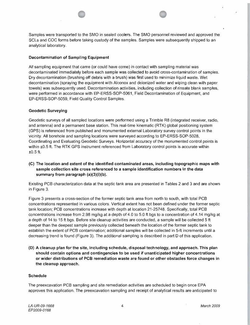
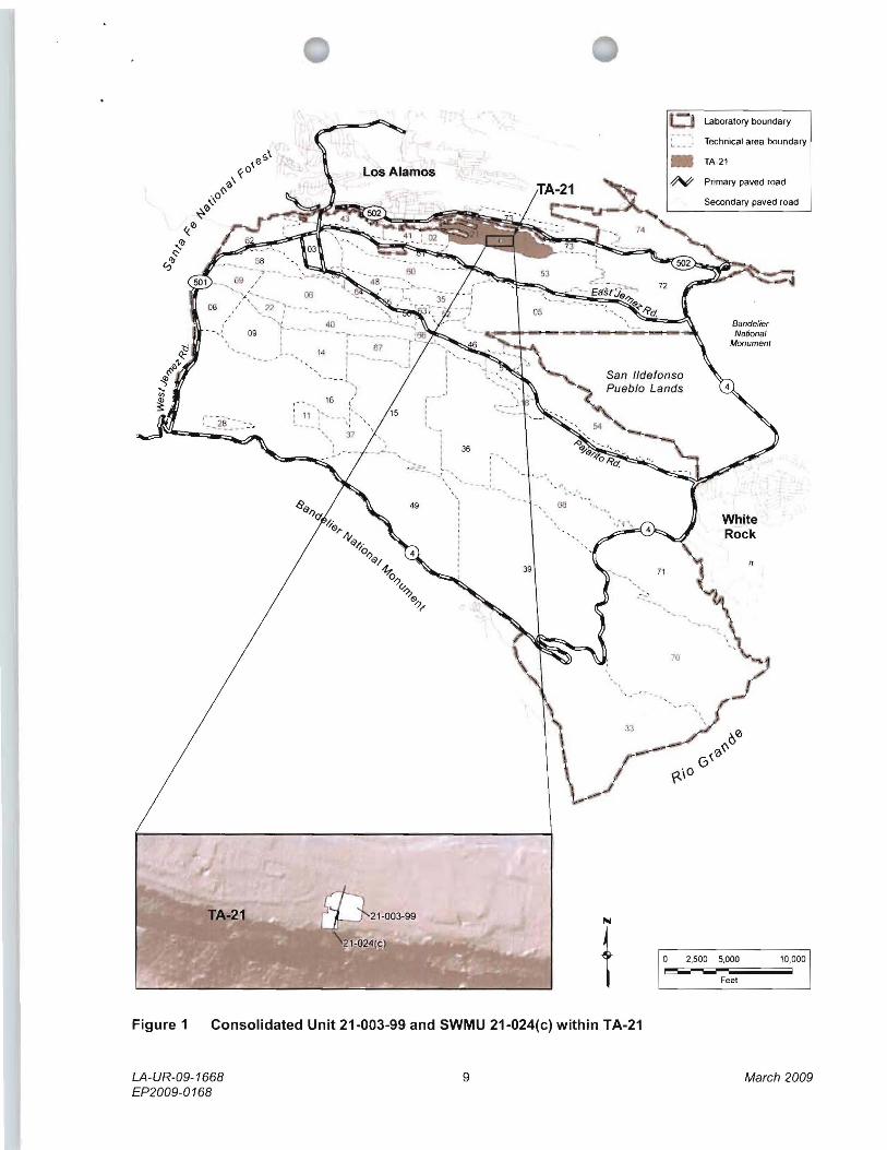
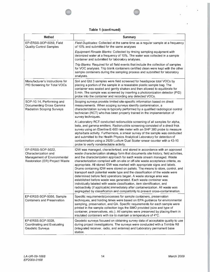