logix 500 digital positioner - pro-quip, inc. · pdf fileflowserve corporation, valtek control...
TRANSCRIPT

51-1Flowserve Corporation, Valtek Control Products, Tel. USA 801 489 8611
GENERAL INFORMATION
The following instructions are designed to assist inunpacking, installing and performing maintenance asrequired on Logix™ 500 Digital Positioners. Series 500is the term used for all the positioners within the family;however, specific numbers indicate features specific toa model: Logix 520 indicates that the positioner usesHART® protocol. Product users and maintenance per-sonnel should thoroughly review this bulletin prior toinstalling, operating, or performing any maintenance onthe valve.
Separate Valtek Flow Control Products Installation,Operation, Maintenance instructions cover the valve(such as IOM 1 or IOM 27) and actuator (such as IOM2 or IOM 31) portions of the system and other acces-sories. Refer to the appropriate instructions when thisinformation is needed.
To avoid possible injury to personnel or damageto valve parts, users must strictly adhere toWARNING and CAUTION notes. Modifying thisproduct, substituting non-factory or inferiorparts, or using maintenance procedures otherthan outlined could drastically affect perfor-mance and be hazardous to personnel and equip-ment, and may void existing warranties.
WARNING: This product has electrical conduitconnections in either thread sizes 0.5-inch NPT orM20 which appear identical but are notinterchangeable. Forcing dissimilar threads
Logix 500 Digital Positioner
Valtek Part No. ?????
together will damage equipment, cause personalinjury and void hazardous location certifications.Conduit fittings must match equipment housingthreads before installation. If threads do not match,obtain suitable adapters or contact a Flowserveoffice.
WARNING: Standard industry safety practicesmust be adhered to when working on this or anyother process control product. Specifically,personal protective and lifting devices must beused as warranted.
Unpacking
1. While unpacking the Logix 500 positioner, checkthe packing list against the materials received. Listsdescribing the system and accessories are includedin each shipping container.
WARNING: When lifting a valve/actuatorassembly with lifting straps, be aware thecenter of gravity may be above the liftingpoint. Therefore, support must be given toprevent the valve/actuator from rotating.Failure to do so can cause serious injury topersonnel or damage to nearby equipment.
2. In the event of shipping damage, contact the ship-per immediately.
3. Should any problem arise, contact a FlowserveFlow Control Division representative.

51-2 Flowserve Corporation, Valtek Control Products, Tel. USA 801 489 8611
Table of Contents
General Information .................................................. 1
Unpacking ................................................................. 1
Logix 500 Overview .................................................. 3
Specifications ............................................................ 3
Principle of Operation ............................................... 4
Mounting and Installation .......................................... 4
Mounting.......................................................... 4
Linear Actuators .............................................. 5
Rotary Actuators .............................................. 7
Tubing Positioner to Actuator .......................... 8
Wiring and Grounding Guidelines ................... 9
Grounding Screw ............................................ 9
Compliance Voltage ........................................ 9
Startup .................................................................... 10
Initial DIP Switch Setting ............................... 11
Quick-Cal Operation...................................... 12
Logix 500 Status Condition Codes ............... 13
HART 275 Handheld Communicator ...................... 16
Limit Switch Unit ..................................................... 16
General .......................................................... 16
Model Selection............................................. 16
Principle of operation .................................... 16
Installation ..................................................... 16
Start-up.......................................................... 16
Troubleshooting ...................................................... 18
Spare Part Kits ........................................................ 20
Mounting Kits .......................................................... 20
Logix 500 Digital Positioneron Valtek 2000 Control Valve

51-3Flowserve Corporation, Valtek Control Products, Tel. USA 801 489 8611
Logix 500 Overview
The Logix 500 is a two-wire, 4-20 mA input digital valvepositioner. The Logix 520 also utilizes the HART proto-col to allow two-way remote communication with thepositioner. The Logix 500 positioner controls single-acting actuators with linear and rotary mountings. TheLogix 500 is completely powered by the 4-20 mA inputsignal. The minimum input signal required to functionis 3.6 mA.
Since the positioner is insensitive to supply pressurechanges and can handle supply pressures from 22 to87 psig (1.5 to 6 barg), a supply regulator is usually not
required; however, in applications where the supplypressure is higher than the maximum actuator pres-sure rating a supply regulator is required to lower thepressure to the actuator’s maximum rating (not to beconfused with operating range). A coalescing air filteris strongly recommended for all applications due to theclose tolerances in the positioner.
NOTE: The air supply must conform to ISA StandardISA 7.0.01 or IEC 770 (a dew point at least 18° F / 10° Cbelow ambient temperature, particle size below five mi-crons – one micron recommended – and oil contentnot to exceed one part per million).
Specifications
Linearity < ± 1.0%
Resolution < 0.1%
Repeatability < 0.2%
Deadband < 0.2%
Table 5: PerformanceCharacteristics (typical)
Operating Temperature Standard -4 – 178° F-20 – 80° C
Low -40 – 178° F-40 – 80° C
Transport and Storage -40 – 178° FTemperature -40 – 80° C
Operating Humidity 0 – 100% non-condensing
Intrinsic Safety EEx ib II C T4/T5/T6;Ta = 65/55/40° C
Table 6: Environmental Conditions
Housing Material Cast aluminum,powder-painted
Soft Goods Nitrile
Weight 2.7 lbs (1.2 kg)
Table 7: Physical Specifications
Output Pressure 0 – 100 % of supply airRange pressure
Output Flow Capacity 1.41 SCFM @ 22 psi(input @ pressure) 2.4 Nm3/h @ 1.5 bar
4.12 SCFM @ 90 psi7.0 Nm3/h @ 6.0 bar
Table 4: Output Signal
Supply Air Quality Free from moisture, oiland dust per ISA-7.0.01
Input Pressure Range 22 – 87 psi (1.5 to 6.0 bar)
Air Consumption 0.047 SCFM @ 22 psi(steady state) 0.08 Nm3/h @ 1.5 bar
0.071 SCFM @ 87 psi0.120 Nm3/h @ 6.0 bar
Table 3: Supply Air
Feedback Shaft 0° to 90° normalRotation 0° to 40° minimum
Table 2: Stroke Output
Input Signal Range 4 - 20 mA(with HART)
Compliance Voltage 12.0 VDC(with HART signal)
Voltage Supply (maximum) 30 VDC
Minimum Required 3.6 mAOperating Current
Table 1: Input Signal

51-4 Flowserve Corporation, Valtek Control Products, Tel. USA 801 489 8611
Figure 1: Logix 520 Principle of Operation
Principle of Operation
The Logix 520 positioner is a digital positioner that in-corporates HART protocol for communication. The po-sitioner consists of three main modules:
1. The microprocessor-based electronic controlmodule includes HART communications and directlocal user interface switches
2. The piezo value-based electro-pneumatic convertermodule
3. The infinite resolution valve position sensor.
The basic positioner operation is best understood byreferring to Figure 1. The complete control circuit ispowered by the two-wire, 4-20 mA command signal.The HART module sends and receives the superim-posed FSK HART digital communications over the4-20 mA signal wires providing two-way remote digitalcommunications to the microprocessor. The analog 4-20mA command is passed to the microprocessor, whereit is compared to the measured valve stem pos-ition. The control algorithm in the processor performscontrol calculations and produces an output commandto the piezo valve, which drives the pneumatic amplifier.The position of the pilot valve in the pneumatic ampli-fier is measured and relayed to the inner loop controlcircuit. This two-stage control provides for more respon-
sive and tighter control than is possible with a singlestage control algorithm. The pneumatic amplifier con-trols the airflow to the actuator. The change of pres-sure and volume of the air in the actuator causes thevalve to stroke. As the valve approaches the desiredposition, the difference between the commanded posi-tion and the measured position becomes smaller andthe output to the piezo is decreased. This, in turn,causes the pilot valve to close and the resulting flow todecrease, which slows the actuator movement as itapproaches, the new commanded position. When thevalve actuator is at the desired position, the pneumaticamplifier output is held at zero, which holds the valvein a constant position.
MOUNTING AND INSTALLATION
MountingBefore starting installation, inspect the digital positionerfor any transit damages. The Logix 500 series positioneris installed with a mounting kit (according to NAMURspecification) to the left-hand actuator support rod.Generally, the unit can be installed in any mountingposition. The stroke feedback is realized by a followerarm and stem clamps. For shipment, the follower arm(maximum stroke of 2.5 inch / 65 mm) is detached fromthe positioner to save space. A follower arm for a 4.0inch (100 mm) stroke must be ordered separately.
Local User Interface
4 – 20 mA+ HART HART
Inner LoopPiezo Control
Stroke
Inner LoopPosition Feedback
1 Digital Control Circuit
2 Electro-pneumatic Converter Module
3 Valve Position Sensor
Filter / Regulator for Supply Air
22 – 87 psi (1.5 – 6.0 bar)Supply Air
∑-
Micro Processor
Gain
Pressure Regulator
Piezo ValvePneumatic Amplifier
ControlValve
+

51-5Flowserve Corporation, Valtek Control Products, Tel. USA 801 489 8611
Mounting the Follower Arm
1. Unscrew the lock nut for follower arm attachment.
2. Place the follower arm (12) on the shaft at the backof the positioner (embossed scale facing the front)and fasten it with the lock nut. The follower pin (15)should point back from the positioner.
CAUTION: Maximum torque 0.18 ft-lbs (0.25 Nm)
Mounting the Stem Clamp Bracket and Take-offArm
1. Attach the stem clamp bracket (8) to the stem clamp(7) and fasten it with two hexagon socket screws(10) and lock washers (9).
2. Attach the take off arm (11) to the stem clampbracket (8) and fasten it with a hexagon socketcapscrew (16) and a washer (17). Ensure the take-off arm slot (11) is centered.
Mounting the Positioner
1. Adjust the actuator to mid-stroke.
2. Pre-assemble the mounting bracket (18) on the leftactuator leg (5) hand-tight with two U-bolts (6), nuts(1) and lock washers’ (2).
The mounting of rod actuators (according to NAMUR)is described in Figure 6.
For the two mounting possibilities of cast yoke actua-tors (according to NAMUR, lEC 534 part 6) refer to Fig-ure 4. After installation, ensure all screw connectionsare tightened correctly and all moving parts are freefrom excessive friction.
Valtek 2000, Kammer KA, Kammer KP, or standardNAMUR linear valves use the same mounting kits.
Mounting of the Logix 500 SeriesPositioner on a Linear PneumaticActuator (NAMUR) (Figure 6)
The mounting of a rod actuator kit (according toNAMUR) is described in an example by using the fol-lowing equipment:
Valve: Standard globe valve or equivalent
Actuator: Single-acting pneumatic actuator
Positioner: Logix 500 with NAMUR mounting kit
Pre-assembly: Valve with actuator (valve stroke ismatched with the actuator stroke)
For mounting, proceed as follows:
Figure 2: Dimensional Drawing of the Logix 500 Digital Positioner
20°
20°
5.2(3)
4.0(9)
4.4(8)
4.3(3)
4(10)
0.67 (17)0.1(9)
0.47 (12)
0.35 (9)
1.1(27.9)
102(26)
2.48(63)
2.2(4)
1.1(8)
Z
0.25-inch 18 NPT
0.25-inch 18 NPT
Y
Right View
inches (mm)
Front View
Bottom ViewBack View
2.48(63)
2.24(57)
1.12(28.5)
1.12(28.5)
0.92(23.4)
0.86(22)

51-6 Flowserve Corporation, Valtek Control Products, Tel. USA 801 489 8611
Figure 3: Basic Adjustment for a Linear Pneumatic Actuator
Figure 4: Yoke Actuator Mounting(according to NAMUR, IEC 534 part 6)
Figure 5: Take-off Arm (standard)
Mounting A
Hexagon HeadScrew
Lock Washer
Mounting B
15 20 30 40 50 60 65 mm
Follower Pin
Follower ArmNutWasher
Act
uato
rS
trok
e
50% Valve Stroke
Stroke = 100% (ATO)
Stroke = 0% (ATC)
Stoke = 0% (ATO) Stroke = 100% (ATC)
mm
6560
50
40
30
20
mm
6560
50
40
30
23
1
ControlMarking
ActuatorStroke
ControlMarking
FollowerPin
Follower Arm

51-7Flowserve Corporation, Valtek Control Products, Tel. USA 801 489 8611
3. Attach the positioner to the pre-assembled mount-ing bracket and fasten it with two hexagon headscrews (4) and two lock washers (3). Check that thefollower pin (15) is inserted in the slot of the take-offarm (11) and the follower arm (12) is positioned ata right angle to the outer edge of the positioner.
4. Tighten all screws and nuts.
NOTE: A slight unsymmetrical mounting increasesthe linearity deviation but does not affect the per-formance of the device. Depending on the actua-tor size and stroke it may be necessary to flip thetake-off arm (Figure 6) by 180° and attach it to theopposite side of the stem clamp bracket (8).
Follower Pin Adjustment
The positioner follower pin must be adjusted to matchthe valve stroke in the following manner:
1. Adjust the follower pin (STROKE + 10 mm) as indi-cated on the follower arm’s embossed scale.
2. Exhaust the actuator.
3. Loosen the follower pin and shift it along the fol-lower arm until the control marking on the feed-back gear (Figure 3) is horizontal (points to thecenter of the feedback potentiometer). Fasten thefollower pin in this position.
4. Adjust the actuator to full stroke and check the fol-lower pin adjustment the same way as described
in step 3. As the actuator strokes, the rotation ofthe feedback gear should be between the innercontrol markings. If the length of rotation is outsidethe control markings, adjust the follower pin far-ther out on the feedback lever to reduce the angleof rotation.
NOTE: Stroke the actuator carefully and ensure thefollower arm does not interfere with valve parts,actuator or positioner. Do not adjust the followerpin (15) too near to the slot end of the take-off arm(11). The minimum lateral distance should be ap-proximately 0.2-inches (5 mm) to prevent bindingof the feedback mechanism.
ROTARY ACTUATORS
Mounting the Logix 500 Series positioneron a quarter-turn actuator (closed by spring)
The mounting of a pneumatic double-piston part-turnvalve actuator (in accordance with VDI/VDE) is describedas an example by using the following equipment:
Part-turn valve actuator: AMG Type SAF, closed byspring
Butterfly damper: 90° rotary angle
Pre-assembly: Mounting block with actuator, actua-tor with damper (damper position is adapted with theactuator stroke)
Figure 6: Mounting on a Rod Actuator (NAMUR)
1 2 3 4
5
6
7
8
9101716
121314
1115
18
1. Nut (4x) 2. Lock washer (4x) 3. Lock washer (2x) 4. Hexagon head screw (2x) 5. Actuator leg (left) 6. U-bolt (2x) 7. Stem clamp 8. Stem clamp bracket 9. Lock washer (2x)10. Hexagon socket screw (2x)11. Take-off arm12. Follower arm13. Washer14. Nut15. Follower pin16. Hexagon socket screw17. Washer18. Mounting bracket

51-8 Flowserve Corporation, Valtek Control Products, Tel. USA 801 489 8611
32
1
4
78
9
56
1. Mounting plate 2. Lock washer 3. Hexagon head screw 4. Mounting block
(not part of the mounting kit)5. Lock washer 6. Nut (4x)7. Hexagon socket screw8. Coupler9. Threaded hole (spring to close)
10. Threaded hole (spring to open)
10
For mounting, proceed as follows:
Mounting the coupler (Figure 7)
Fasten the coupling by using one of the two 90° stag-gered threaded holes, which allows different actuatormounting (closed by spring / opened by spring).
1. Screw the hexagon socket screw (7) into the appro-priate threaded hole (9 for closed-by-spring; 10 foropened-by-spring) in the coupling (8), so that thescrew is not protruding into the coupling hole.
2. Place the coupling on the positioner’s rotary con-nection. Ensure the hexagon socket screw (7)points to the recess on the rotary connection.
3. Fasten the socket screw (7) by using a hexagonsocket screw key (3 mm).
Mounting the positioner (Figure 7)
1. Attach the mounting plate (1) to the positioner andfasten it with two hexagon head screws (3) and lockwashers (2).
2. Place the mounting plate (1) with the positioneronto the mounting block (4) of the actuator. Ensurethe coupler (8) fits on to the shaft of the quarter-turnconnection on the part-turn valve actuator.
3. Hand-tighten the plate (1) onto the actuator withfour nuts (5) and lock washers (6), center it andfasten the nuts.
4. Tighten all screws and nuts.
Tubing Positioner to ActuatorAfter mounting has been completed, tube the positionerto the actuator using the appropriate compression fit-ting connectors:
Air connections: 1/4” NPT (standard air connection)
Auxiliary power: Pressurized air or permissiblegases, free of moisture and dust in according withIEC 770 or ISA 7.0.01.
Pressure range: 22 – 87 psi (1.5 – 6.0 bar)
For connecting the air piping, the following notes shouldbe observed:
1. The positioner passageways are equipped withfilters, which remove medium and coarse size dirtfrom the pressurized air. If necessary, they areeasily accessible for cleaning.
2. Supply air should meet IEC 770 or ISA 7.0.01requirements. A coalescing filter should be installedin front of the supply air connection Z. Now connect
Figure 7: Mounting a Part-turn Valve Actuator (in acc. with VDI/VDE)

51-9Flowserve Corporation, Valtek Control Products, Tel. USA 801 489 8611
the air supply to the filter, which is connected to theLogix 500 series positioner.
3. With a maximum supply pressure of 87 psi (6 bar)a regulator is not required.
4. With an operating pressure of more than87 psi (6 bar), a reducing regulator is required. Theflow capacity of the regulator must be larger thanthe air consumption of the positioner (4.12 scfm @87 psi / 7 Nm3/hr @ 6 bar).
5. Connect the outlet connector Y of the positioner tothe actuator with tubing, independent of the action(direct or reverse).
Wiring and Grounding Guidelines
Electrical connections: signal cable with cable passage(NPT, PG13.5, or M20 x 1.5) to terminals 2 x 2.5 mm
Input signal: 4 – 20 mA, 4 – 12 mA, 12 – 20 mA
NOTE: Observe the minimum requirements of voltageand equivalent electrical load: 12.0 VDC / 600 Ω / at20 mA.
The performance is ensured only for a minimum inputcurrent of 3.6 mA.
For wiring, the following notes should be observed:
NOTE: The input loop current signal to the Logix 500should be in shielded cable. Shields must be tied to aground at only one end of the cable to provide a placefor environmental electrical noise to be removed fromthe cable. In general, shield wire should be connectedat the source. (Figure 8)
Connect the 4-20 mA current source to terminals +11and -12 (Figure 8).
Grounding Screw
The grounding screw, located inside the positionercover, should be used to provide the unit with an ad-equate and reliable earth ground reference. This groundshould be tied to the same ground as the electrical con-duit. Additionally, the electrical conduit should be earthgrounded at both ends of its run. The grounded screwmust not be used to terminate signal shield wires.
Compliance Voltage (Figure 9)
Output compliance voltage refers to the voltage limitthe current source can provide. A current loop systemconsists of the current source, wiring resistance, bar-rier resistance (if present), and the Logix 500 imped-ance. The Logix 500 requires that the current loopsystem allow for a 12.0 VDC drop across the positionerat maximum loop current.
CAUTION: Never connect a voltage source directlyacross the positioner terminals. This could causepermanent circuit board damage.
In order to determine if the loop will support the Logix500, perform the following calculation.
Voltage = Compliance Voltage (@CurrentMAX
) - Current
MAX*(R
barrier + R
wire)
The calculated voltage must be greater than 12.0 VDCin order to support the Logix 500.
Example: DCS Compliance Voltage = 19 V
Rbarrier
= 300 Ω (if present)
Rwire
= 25 Ω
CURRENTMAX
= 20 mA
Voltage = 19 V - 0.020 A*(300 Ω + 25 Ω) = 12.5 V
Figure 8: Wiring Diagram
Connection Description
+11 Input +
-12 Input -
+41* Limit switch 1 +
-42* Limit switch 1 -
+51* Limit switch 2 +
-52* Limit switch 2 -
Y Pneumatic output signal (outlet)
Z Air supply (inlet)
* = Optional connection
Table 8: Connection Table
PIEZORELAY
POT.
LS1
LS2
Internal HousingEARTH Terminal External Housing
Limit Switch 1
Limit Switch2
4-20 mA Signal
Connect Shield at Source Ground
-
+4-20 mA Current Source
Shielded Cable
Y
Z

51-10 Flowserve Corporation, Valtek Control Products, Tel. USA 801 489 8611
Cnetwork (µF) < - 0.0032
22 ρF 0.000022 µF foot foot
65 (300 + 50
+ 390)
Cnetwork
(µF)
Ccable
0.08 µF
0.000022 µF/foot
- 0.0032 = 0.08 µF= Cnetwork
(µF)(Max)
The voltage 12.5 V is greater than the required 12.0 V;therefore, this system will support the Logix 500. TheLogix 500 has an input resistance equivalent to 625 Ωat a 20 mA input current.
Cable Requirements
The Logix 520 digital positioner utilizes the HART com-munication protocol. This communication signal issuperimposed on the DC 4-20 mA current signal. Thetwo frequencies used by the HART protocol are 1200 Hzand 2200 Hz. To prevent distortion of the HART com-munication, cable capacitance and cable length restric-tions must be calculated. The cable length must be lim-ited if the capacitance is too high. Selecting a cablewith lower capacitance/foot rating will allow longer cableruns. In addition to cable capacitance, the network re-sistance also affects the allowable cable length.
To calculate the maximum network capacitance use thefollowing formula.
65 (Rbarrier + Rwire + 390)
Example: Rbarrier = 300 Ω (if present)
Rwire = 50 Ω
Ccable = =
Max. Cable Length =
Max. Cable Length = = 3636 ft.
Figure 9: Compliance Voltage
50012.0 VDC
To control cable resistance, No. 24 AWG cable shouldbe used for runs less than 5000 feet. For cable runs longerthan 5000 feet, No. 20 AWG cable should be used.
Electromagnetic Compatibility
The Logix 520 digital positioner has been designed tooperate correctly in electromagnetic (EM) fields foundin typical industrial environments. Care should betaken to prevent the positioner from being used inenvironments with excessively high EM fieldstrengths (greater than 10 V/m). Portable EM devicessuch as hand-held two-way radios should not beused within one feet of the device.
Ensure proper wiring and shielding techniques of thecontrol lines, and route control lines away fromelectromagnetic sources that may cause unwantednoise. An electromagnetic line filter can be used tofurther eliminate noise (Flowserve Part Number10156843).
In the event of a severe electrostatic discharge near thepositioner, the device should be inspected to ensurecorrect operability. It may be necessary to recalibratethe Logix 520 positioner to restore operation.
STARTUP
Logix 500 Local Interface operation
The Logix 500 local user interface allows the user toconfigure the basic operation of the positioner, tune theresponse, and calibrate the positioner without additionaltools or configurators. The local interface consists of aQuick-Cal™ button for automatic zero and span set-ting, along with two jog buttons for spanning valve/actuators with no fixed internal stop in the open posi-tion. There is also a switch block containing eightswitches. Six of the switches are for basic configura-tion settings and one is for calibration options and one

51-11Flowserve Corporation, Valtek Control Products, Tel. USA 801 489 8611
is for future enchancements. There is also a rotaryselector switch for adjusting the positioner gain settings.For indication of operational status or alarm conditionsthere are also three LEDs on the local user interface.
Initial DIP Switch Setting
Before placing the unit in service, set the DIP switchesin the Configuration and Cal boxes to the desired con-trol options.
NOTE: The switch settings in the Configuration box areactivated only by pressing the Quick-Cal button or byutilizing the stroke calibration features provided by ahandheld or by Flowserve PC software.
Operation of Configuration DIP Switches Setup
The first six DIP switches are for basic configuration
1. Air Action – Must be set to match the configurationof the valve/actuator mechanical configuration.
ATO (air-to-open) – Selecting ATO if increasingoutput pressure from the positioner is tubed so it willcause the valve to open.
ATC (air-to-close) – Selecting ATC if increasingoutput pressure from the positioner is tubed so it willcause the valve to close.
2. Signal at Closed – Normally this will be set to 4 mAfor an air-to-open actuator, and 20 mA for an air-to-close actuator configuration.
Selecting 4 mA will make the valve fully closedwhen the signal is 4ma and fully open when thesignal is 20 mA.
Selecting 20 mA will make the valve fully closedwhen the signal is 20 mA and fully open when thesignal is 4 mA.
3. Pos. Characterization
Select Linear if the actuator position should bedirectly proportional to the input signal.
Select Optional if another characteristic is desired,which is set in conjunction with the next switch,labeled Optional Pos. Char.
4. Optional Pos. Char. – If the Pos. Characterizationswitch is set to optional, this switch is active with thefollowing options:
The =% option will characterize the actuatorresponse to the input signal based on a standard30:1 equal percent rangability curve.
If Custom is selected, the positioner will be charac-terized to a custom table that must be set-up usinga properly configured HART 275 handheld or otherhost software.
5. Auto Tune – This switch controls whether thepositioner will auto tune itself every time theQuick-Cal button is pressed
On enables an auto tune feature that will automati-cally determine the positioner gain settings every
Figure 10: Logix 500 Local Interface
EnhancedQuick-CalConfigurationSwitches
Autotune
LockoutSwitch
4-20 mA inputwith HARTCommunications
Terminals for Optional Limit Switches
Quick-Cal Button
Gain Selector
Jog CalibrateButtons
LED StatusLights

51-12 Flowserve Corporation, Valtek Control Products, Tel. USA 801 489 8611
time a Quick-Cal is performed based on the settingof the rotary Gain switch.
If the rotary Gain selector switch is set to E with theauto tune switch On, a Flowserve nominalresponse tuning set will be calculated and used.
If the rotary Gain selector switch is set to D, C, B, orA with the Auto Tune switch On, progressivelylower gain settings will be calculated and used.
If the rotary Gain selector switch is set to F, G, or Hwith the Auto Tune switch On, progressively highergain settings will be calculated and used.
Off forces the positioner to use one of the factorypreset tuning sets determined by the rotary Gainselector switch. Settings A through H are progres-sively higher gain predefined tuning sets.
6. Config. Switches — By selecting Enabled, theLogix 500 will read all of the configuration switcheseach time a Quick-Cal is performed to determinethe configuration.
Selecting Disabled retains the last configuration inmemory (from the last successful calibration) be-fore the switch was set to Disabled. With this settinga Quick-Cal only zeros and spans the positioner.
Setup of the Cal DIP Switch for the QuickCalibration operating mode1. Select Auto if the valve/actuator assembly has an
internal stop in the 100% stroke position. In Automode the positioner will fully close the valve andregister the 0% position and then open the valve tothe stop to register the 100% position when per-forming a self-calibration. See detailed instructionsin the next section on how to perform an autopositioner calibration.
2. Select Jog if the valve/actuator assembly has nocalibration stop in the open position. In the Jogmode the positioner will fully close the valve for the0% position and then wait for the user to set theopen position using the Jog buttons labeled with theup and down arrows. See the detailed instructionsin the next section on how to perform a manualcalibration using the Jog buttons.
WARNING: During the Quick-Cal operation thevalve may stroke unexpectedly. Notify properpersonnel that the valve will stroke, and makesure the valve is properly isolated.
Quick-Cal OperationThe Quick-Cal button is used to locally initiate a calibra-tion of the positioner. Pressing and holding the Quick-Calbutton for approximately three seconds will initiate thecalibration. If the Config-Switches option is enabled, thesettings of all the configuration switches are read andthe operation of the positioner adjusted accordingly.
The Gain Selector switch is also read and action will betaken to adjust the gain according to the settings of thecalibration switches as described in the previous section.A Quick-Cal can be aborted at any time by briefly pressingthe Quick-Cal button and the previous settings will beretained.
If the Quick calibration switch (not to be confused with theQuick-Cal button) is set to Auto and the valve/actuatorassembly has the necessary internal stops, the calibra-tion will complete automatically. While the calibration is inprogress you will notice a series of different lights flash-ing indicating the calibration progress. When the lightsreturn to a sequence that starts with a green light, thecalibration is complete. (See the appendix for an expla-nation of the various light sequences.)
WARNING: When operating using local control of thevalve, the valve will not respond to external com-mands. Notify proper personnel that the valve will notrespond to remote command changes, and make surethe valve is properly isolated.
If the Quick calibration switch is set to Jog, the calibrationwill initially close the valve then cause a small jump in thevalve position. The jog calibration process will onlyallow the user to manually set the span; zero posi-tion is automatically always set at the seat. If an el-evated zero is needed a handheld or other PC basedconfiguration software is required. The LEDs will then flashin a sequence of Y-R-R-G (yellow-red-red-green) whichindicates the user must now use the Jog keys to manu-ally position the valve to approximately 100%. When thevalve is approximately 100% open press both Jog but-tons simultaneously to proceed to the next step. The valvewill then stroke and then wait while flashing the Y-R-R-Gsequence again, allowing the user to adjust the valveposition a second time to exactly 100% using the Jogbuttons. When the stem is properly positioned press bothJog buttons simultaneously again to register the 100%position and proceed. No more user actions are requiredwhile the calibration process is completed. When the lightsreturn to a sequence that starts with a green light the cali-bration is complete. (See the appendix for an explanationof the various light sequences.)
Local control of valve position — Can be done fromthe user interface by holding both jog buttons and thensimultaneously pressing the Quick-Cal button. While inthis mode the LEDs will flash a Y-G-R-R (yellow-green-red-red) sequence. To exit the local control mode and re-turn to normal operation, briefly press Quick-Cal.
Factory reset — hold Quick-Cal button while applyingpower and all of the internal variables including calibra-tion will be reset to factory defaults. The positioner mustbe re-calibrated after a factory reset. Tag names and otheruser configured limits, alarm settings, and valve informa-tion will also need to be restored. A factory reset will al-ways reset the command source to analog 4-20 mA.

51-13Flowserve Corporation, Valtek Control Products, Tel. USA 801 489 8611
Colors Identifier Indication and resolution
G - - - Any sequence starting with a Green light flashing first is a normal operating mode and indi-cates that there are no internal problems.
GGGG 1 No errors, alerts, or warnings; and the unit is in analog control mode.
GGGY 2 MPC active - The command is below the user set limit for tight shutoff feature. This is a normal condition for a closed valve. The factory default setting is 1% command. To clear the condition use handheld or Flowserve supplied software to reset the MPC if the range is incorrect or adjust the command signal above the specified MPC value.
GGYG 3 Digital command mode - The analog 4-20 mA input signal is ignored in this mode and a handheld or handheld or Flowserve supplied software is needed to change the position command. (Note a factory reset is the only method to reset the command back to analog control mode from the local interface if a PC or handheld configurator is not available. A reset will cause the loss of other data. See section 5 in the main document for more infor-mation.)
GGYR 4 Cycle limit - The cycle limit set by the user has been exceeded. To clear use handheld or Flowserve supplied software to reset.
GGRY 5 Travel limit -The total accumulated travel limit set by the user has been exceeded. To clear use handheld or Flowserve supplied software to reset.
GYYR 6 Soft Stop Lower - The unit is being commanded to exceed a user defined lower travel limit and the
internal software is holding the position at the limit. To clear the condition use handheld or Flowserve supplied software to reset the limit if more travel is needed or adjust the command signal back in the specified range.
GYRY 7 Soft Stop Upper - The unit is being commanded to exceed a user defined upper travel limit and the internal software is holding the position at the limit. To clear the condition use handheld or Flowserve supplied software to reset the limit if more travel is needed or adjust the command signal back in the specified range.
GRYR 8 Position Lower - The position has reached or is exceeding a user defined lower travel indicator similar to a limit switch indicator. To clear the condition use handheld or Flowserve supplied software to reset the indicator if more travel is needed or adjust the command signal back in the specified range.
GRRY 9 Position Upper - The position has reached or is exceeding a user defined upper travel indicator similar to a limit switch indicator. To clear the condition use handheld or Flowserve supplied software to reset the indicator if more travel is needed or adjust the command signal back in the specified range.
Y - - - Any sequence starting with a yellow light indicates that the unit is in a special calibration or test mode, or that there was a calibration problem.
YGYG 10 Signature test in progress- This is a test initiated by Flowserve supplied software that can only be cancelled by that software.
YYYG 11 Loop Calibration in Progress - Calibration sequence controlled by a handheld or Flowserve supplied software that can only be cancelled by that software.
YRGG 12 Stroke Calibration in Progress - Calibration sequence started either using the local Quick-Cal button or by a handheld or Flowserve supplied software. It may be cancelled by briefly pushing the Quick-Cal button.
YGRR 13 JOG Control Mode - the unit has been placed in a local override mode where the valve can only be stroked using the two local jog buttons. It may be cancelled by briefly pushing the Quick-Cal button.
Table 9: Logix 500 Status Condition Codes

51-14 Flowserve Corporation, Valtek Control Products, Tel. USA 801 489 8611
YYYR 14 Command 0 saturated - Calibration error indicating that the 4-20 mA signal correspond-ing to 0% position was out of range. Adjust the signal to the correct range and re-do the calibration. This error may be cleared by briefly pushing the Quick-Cal button, which will force the positioner to use the parameters from the last good calibration.
YYRY 15 Command 100 saturated - Calibration error indicating that the 4-20 mA signal corre-sponding to 100% position was out of range. Adjust the signal to the correct range and re-do the calibration. This error may be cleared by briefly pushing the Quick-Cal button, which will force the positioner to use the parameters from the last good calibration.
YYRR 16 Command span - Calibration error indicating that the 4-20 mA signal was below the mini-mum calibration span. The minimum calibration span is 1.28 mA. This error may be cleared by briefly pushing the Quick-Cal button, which will force the positioner to use the parame-ters from the last good calibration.
YRRG 17 Waiting for JOG set point from User - only used during Jog calibration see explanation in Quick-Cal section of main document for operation.
YRYG 18 Setting IL Offset (in Stroke Cal) - An automatic step in the calibration process that is done with the valve at 50% position. This must be completed for proper calibration.
YRYY 19 Feedback no-motion during calibration - Indicates that there was no motion of the actu-ator based on the current stroke time configuration. Check linkages and air supply to make sure the system is properly connected. If the time out occurred because the actuator is very large then simply retry the Quick-Cal and the positioner will automatically adjust for a larger actuator by doubling the time allowed for movement. This error may be cleared by briefly pushing the Quick-Cal button, which will force the positioner to use the parameters from the last good calibration.
YRYR 20 Feedback 0 saturated - Calibration error indicating that the position sensor was out of range during the calibration. To correct the condition, adjust the positioner mounting, link-age or feedback potentiometer to move the position sensor back into range then restart the calibration. This error may be cleared by briefly pushing the Quick-Cal button, which will force the positioner to use the parameters from the last good calibration.
YRRY 21 Feedback 100 saturated - Calibration error indicating that the position sensor was out of range during the calibration. To correct the condition, adjust the positioner mounting, link-age or feedback potentiometer to move the position sensor back into range then restart the calibration. This error may be cleared by briefly pushing the Quick-Cal button, which will force the positioner to use the parameters from the last good calibration.
YRRR 22 Feedback span - The range of motion of the position feedback arm was too small. Check for loose linkages and/or adjust the feedback pin to a position closer to the follower arm pivot to create a larger angle of rotation. This error may be cleared by briefly pushing the Quick-Cal button, which will force the positioner to use the parameters from the last good calibration.
YRGR 23 Feedback unstable during calibration - Check for loose linkages or loose positioner sen-sor. This error may be cleared by briefly pushing the Quick-Cal button, which will force the positioner to use the parameters from the last good calibration.
YRGY 24 Feedback unstable setting IL Offset - Check for loose linkages or loose positioner sen-sor. This can also be caused by over tightened packing, very sticky packing, or very high gain settings. This error may be cleared by briefly pushing the Quick-Cal button, which will force the positioner to use the parameters from the last good calibration.
Colors Identifier Indication and resolution
Table 9: Logix 500 Status Condition Codes (continued)

51-15Flowserve Corporation, Valtek Control Products, Tel. USA 801 489 8611
R - - - Any sequence starting with a red light indicates that there is an operational problem with the unit.
RGRR 25 Position Deviation - The position has exceeded user defined error band between com-mand and position.
RYGG 26 Initializing, or LED test mode - This sequence should only be visible for 3 sequences when powering up the unit.
RYYY 27 Hall sensor non-motion - Check to make sure the air supply is connected. This error may be cleared by briefly pushing the Quick-Cal button, which will force the positioner to use the parameters from the last good calibration. If the positioner still does not operate replace the pneumatic relay assembly.
RYYR 28 Hall sensor lower position - Check to make sure the air supply is connected. This error may be cleared by briefly pushing the Quick-Cal button, which will force the positioner to use the parameters from the last good calibration. If the positioner still does not operate replace the pneumatic relay assembly.
RYRY 29 Hall sensor upper position - Check to make sure the air supply is connected. This error may be cleared by briefly pushing the Quick-Cal button, which will force the positioner to use the parameters from the last good calibration. If the positioner still does not operate replace the pneumatic relay assembly.
RRGG 30 1.23v reference - Bad electronic assembly, replace.
RRGR 31 12-bit A/D reference - Bad electronic assembly, replace.
RRYG 32 Temperature limit - The internal positioner temperature is currently exceeding operational limits of -40ºF (-40ºC) or 185ºF (85ºC).
RRYY 33 Piezo voltage - Bad electronic assembly, replace.
RRYR 34 Board current high - Check internal wiring and connectors for electrical shorts, if no shorts bad electronic assembly, replace.
RRRG 35 12-bit D/A reference - Bad electronic assembly, replace.
RRRY 36 EEprom checksum error - The checksum of the internal data has become corrupted. Cycle power and complete a Quick-Cal if needed. Check internal data to verify correct set-tings. If the error still occurs, bad electronic assembly, replace.
Colors Identifier Indication and resolution
Figure 11: Limit Switch Unit
Table 9: Logix 500 Status Condition Codes (continued)

51-16 Flowserve Corporation, Valtek Control Products, Tel. USA 801 489 8611
HART 275 HANDHELD COMMUNICATORAND SOFTTOOLS CONFIGURATION ANDDIAGNOSTIC SOFTWAREThe Logix 520 supports and is supported by the HART275 Handheld Communicator. The DD and the manu-als listed below can be obtained from the HARTCommunication Foundation or from your Flowserve rep-resentative. For more information please see the fol-lowing guides:
• Product Manual for the HART Communicator
• Logix 520 Digital Positioner with HART 275Communicator User Guide
Flowserve corporation has written custom configura-tion and diagnostic software for the Logix 500 seriescalled SoftTools™. This software and the SoftToolsQuick Start Guide are available from a Flowserve rep-resentative.
LIMIT SWITCH UNIT (Optional)CAUTION: The installation of explosion proof elec-trical equipment must comply with the procedurescontained in the certificates of conformance. Coun-try specific regulations may apply. Electrical safetyis determined only by the power supply device(Positioner operation with limited voltage only).
GeneralThe Logix 500 digital positioner can be equipped withan additional limit switch unit, designed as a two-wiresensor in accordance with NAMUR. The low voltageand current characteristics of these sensors allowsoperation in hazardous areas.
Model SelectionTo select the suitable Logix 500 version see productinformation.
Principle of operationThe stroke of the diaphragm actuator or the rotary angleof the rotary valve actuator is picked up by a stroke
lever or by a coupling at the actuator connection. Thelever/coupling moves the vane into the slot of the limitswitches LS1 or LS2 via shaft. The sensors are de-signed as a proximity vane type switch. The switchingfunction is triggered if a ferromagnetic object (vane) isinserted between the coils. The switching point can beset by adjustment of the vane.
InstallationThe limit switch unit is delivered already fitted to thepositioner and can not be retrofitted.
Start-upAfter the Logix 500 digital positioner start-up in accor-dance with the application is complete, the limit switchunit can be adjusted and operation can be effected.For adjustment remove the positioner cover. Figure 14shows the maximum switching range of the limitswitches LS1 and LS2.
The switching points of the limit switches can be set byan adjustment of the vane as follows (Figure 13):
1. Loosen the knurled screw (Figure 13) at the strokelever axis (1/2 to 1 rotations).
2. Move the positioner to the first switching position.
3. Set the switching point of the limit switch LS2 byadjusting the vane of the lower switch. For adjust-ment turn the corresponded slotted screw clock-wise or counterclockwise.
4. Move the positioner to second switching position.
5. Set the switching point of the limit switch LS1 byadjusting the vane of the upper switch. For adjust-ment turn the corresponded slotted screw clock-wise or counterclockwise.
6. Tighten the knurled screw.
7. Check the two switching points and repeat theadjustment steps 1 to 6, if necessary.
Figure 12: Principle of Operation
Linear Version Rotary Version Rotary Valve Actuator
Limit Switch Unit Limit Switch Unit
+
-
+
-
Diaphragm Actuator
StrokeLever
Butterfly Damper

51-17Flowserve Corporation, Valtek Control Products, Tel. USA 801 489 8611
Figure 13: Proximity Vane Type Switch with Positioner (side view)
Type Two-wire - SJ 3,5-N SJ 3,5-SN SJ 5-Nproximity vane type switch
General Operating voltage 8Vdc
Application Limit sensing for positioners
Switches fitted 2 proximity vane type switches (delivery in combinationonly with positioner; can not be retrofitted)
Switching action Normally open (NO) in acc. with NAMUR (DIN 19234)
Dimensions The limit switch unit does not change the Logix 500dimensions
Supply Supply voltage Umax. ≤ 16Vdc
Supply current Imax. ≤ 52mA
Output signal With target ≤ 1mA
Without target ≤ 3mAShort circuit-proofed
Control characteristics Switching hysteresis 5% ( = 1mm STROKE)(in acc. with 20mm STROKE)
Repeatability 0.05% ( = 0.01mm STROKE)
Ambient temperature sensitivity < 1.5% (0.3mm ) / 10K
Vibration sensitivity < 1% at 2g (0.5...500 Hz) in accordance with IEC 65Bsection 133 (draft)
Environmental - Operating temperature -25 C...+100 C -40 C...+100 C -25 C...+100 Cconditions Intrinsic safety EEx ib II C T4/T5/T6; Tu=80/65/50 C
in accordance with EN 50014 and EN 50020
Table 10: Technical Data
LSI
AdjustmentScrews
Knurled Knob
LS2
L-
L+N

51-18 Flowserve Corporation, Valtek Control Products, Tel. USA 801 489 8611
* MPC (Minimum position cutoff)
Failure Probable Cause Corrective actionNo LED is blinking 1. Current source below 3.6 mA
2. Incorrect wiring polarity
1. Verify current source is outputting at least 3.6 mA
2. Check wiring for correct polarityErratic communications 1. Current source bandwidth not limited to
25Hz2. Maximum cable length or cable
impedance exceeded
3. HART modem connected to PC RS-232 port not receiving enough power
4. Interference with I.S. barrier
5. Current source stripping (filtering) HART signal.
1. Maximum allowable current source rate of change is 924 mA per second
2. Check cable conductor size, length and capacitance. Refer to 'Cable Requirements' on page 11.
3. Verify laptop battery is not low
4. Must use HART compatible I.S. barrier
5. Use the HART filter (VHF) available from Flowserve
Unit does not respond to analog commands
1. Unit is in digital command mode
2. Error occurred during calibration
1. Switch to analog command mode with handheld communicator or Soft-Tools.
2. Correct calibration error. RecalibrateValve position reading is not what is expected
1. Stem position sensor mounting is off 180 degrees
2. Stroke not calibrated3. Tight shutoff (M.P.C.)* is active4. Custom characterization or soft stops
activePosition is driven fully open or closed and will not respond to com-mand
1. Stroke not calibrated2. Inner-loop hall sensor not connected3. Wrong air action entered in software
4. Actuator tubing backward5. Electro-pneumatic converter
malfunctioning6. Control parameter inner-loop offset is too
high/low
1. Calibrate valve stroke2. Verify hardware connections3. Check ATO (Air-to-open) and ATC
(Air-to-Close) settings. Recalibrate4. Verify ATO/ATC actuator tubing5. Replace electro-pneumatic converter
6. Adjust inner-loop and see if proper control resumes
Sticking or hunting oper-ation of the positioner
1. Contamination of the electro-pneumatic converter.
2. Control tuning parameters not correct
1. Check air supply for proper filtering and meeting ISA specificationsISA-7.0.01
2. Lower proportional gain settings
Figure 14: Adjustable Switching Range
Troubleshooting Logix 500 Digital Positioners
Factory setting of the limit switches LS1 and LS2: 0% – 3% from the end position
0 10 20 30 80 90 100% 0 10 20 30 40 50 60 70 80 90 100%850
Rotary Version
LS1 LS2 LS1 LS2
Switch output Switch outputLinear Version
Stroke Rotary angle

51-19Flowserve Corporation, Valtek Control Products, Tel. USA 801 489 8611
Figure 15: Exploded View
Cover(Item No. 1)
ElectronicControl Boards(Item No. 2)
E/P Piezo DriverPneumatic Amplifier Relay Unit(Item No. 3)
Feedback Potentiometer Assembly(Item No. 4)
Feedback Gear & Shaft(Item No. 5)
Limit SwitchAssembly(Item No. 6)
Base Housing(Item No. 7)
Follower(Item No. 8)Follower arm
51-20 Flowserve Corporation, Valtek Control Products, Tel. USA 801 489 8611
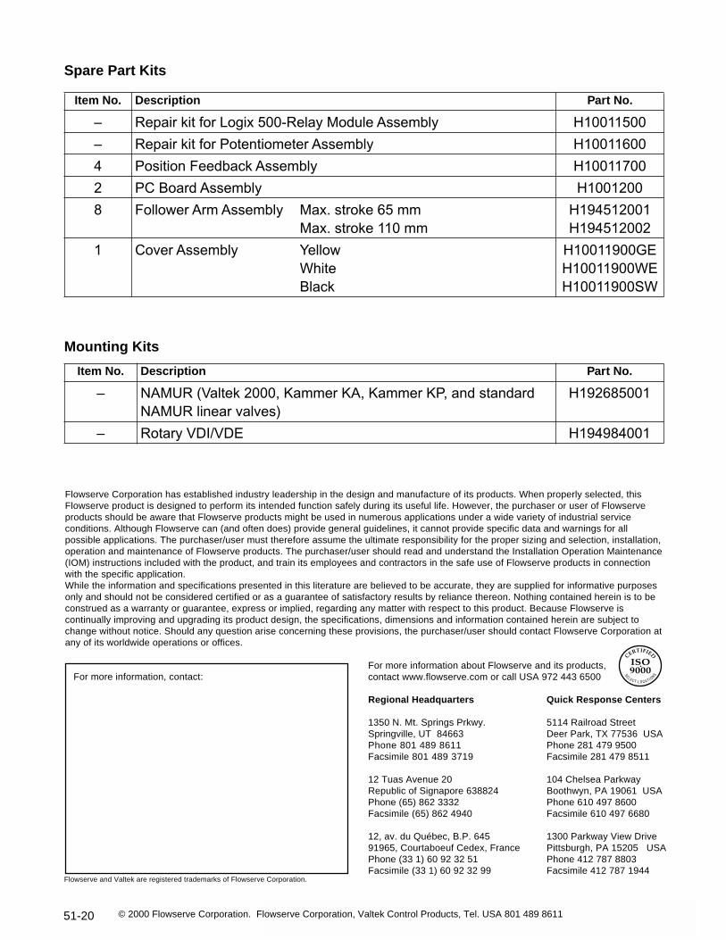
Spare Part Kits
Mounting Kits
Flowserve Corporation has established industry leadership in the design and manufacture of its products. When properly selected, thisFlowserve product is designed to perform its intended function safely during its useful life. However, the purchaser or user of Flowserveproducts should be aware that Flowserve products might be used in numerous applications under a wide variety of industrial serviceconditions. Although Flowserve can (and often does) provide general guidelines, it cannot provide specific data and warnings for allpossible applications. The purchaser/user must therefore assume the ultimate responsibility for the proper sizing and selection, installation,operation and maintenance of Flowserve products. The purchaser/user should read and understand the Installation Operation Maintenance(IOM) instructions included with the product, and train its employees and contractors in the safe use of Flowserve products in connectionwith the specific application.While the information and specifications presented in this literature are believed to be accurate, they are supplied for informative purposesonly and should not be considered certified or as a guarantee of satisfactory results by reliance thereon. Nothing contained herein is to beconstrued as a warranty or guarantee, express or implied, regarding any matter with respect to this product. Because Flowserve iscontinually improving and upgrading its product design, the specifications, dimensions and information contained herein are subject tochange without notice. Should any question arise concerning these provisions, the purchaser/user should contact Flowserve Corporation atany of its worldwide operations or offices.
For more information, contact:For more information about Flowserve and its products,contact www.flowserve.com or call USA 972 443 6500
Regional Headquarters
1350 N. Mt. Springs Prkwy.Springville, UT 84663Phone 801 489 8611Facsimile 801 489 3719
12 Tuas Avenue 20Republic of Signapore 638824Phone (65) 862 3332Facsimile (65) 862 4940
12, av. du Québec, B.P. 64591965, Courtaboeuf Cedex, FrancePhone (33 1) 60 92 32 51Facsimile (33 1) 60 92 32 99
Quick Response Centers
5114 Railroad StreetDeer Park, TX 77536 USAPhone 281 479 9500Facsimile 281 479 8511
104 Chelsea ParkwayBoothwyn, PA 19061 USAPhone 610 497 8600Facsimile 610 497 6680
1300 Parkway View DrivePittsburgh, PA 15205 USAPhone 412 787 8803Facsimile 412 787 1944
Flowserve and Valtek are registered trademarks of Flowserve Corporation.
© 2000 Flowserve Corporation. Flowserve Corporation, Valtek Control Products, Tel. USA 801 489 8611
Item No. Description Part No.
– Repair kit for Logix 500-Relay Module Assembly H10011500
– Repair kit for Potentiometer Assembly H10011600
4 Position Feedback Assembly H10011700
2 PC Board Assembly H1001200
8 Follower Arm Assembly Max. stroke 65 mmMax. stroke 110 mm
H194512001H194512002
1 Cover Assembly YellowWhiteBlack
H10011900GE H10011900WEH10011900SW
Item No. Description Part No.
– NAMUR (Valtek 2000, Kammer KA, Kammer KP, and standard NAMUR linear valves)
H192685001
– Rotary VDI/VDE H194984001