location of flaws in barrel
TRANSCRIPT

/ '
)
Tfl 473
.S3
Copy 1
DEPARTMENT OF COMMERCE
Scientific PapersOF THE
Bureau of StandardsS. W. STRATTON. Director
No. 343
LOCATION OF FLAWS IN RIFLE-BARREL STEELBY MAGNETIC ANALYSIS
BY
R. L. SANFORD, Associate Physicist
and
WM. B. KOUWENHOVEN, Consulting Engineer
Bureau of Standards
ISSUED OCTOBER 3, 1919
jCj.Xlb"'^ ^
PRICE, 5 CENTSSold only by the Superintendent of Documents, Government Printing Office
Washington, D. C.
WASHINGTONGOVERNMENT PRINTING OFFICE
1919
''^^^''Zf^nr
53
D« Of D.ocr 26 1919
o
LOCATION OF FLAWS IN RIFLE-BARREL STEEL BYMAGNETIC ANALYSIS
By R. L. Sanford and Wm. B. Kouwenhoven
CONTENTSPage
I. Introduction 219
II. Theory 219
III. Description of apparatus and procedure 221
IV. Preliminary study and adjustment 223
V. Experimental results , 225
VI. Summary 228
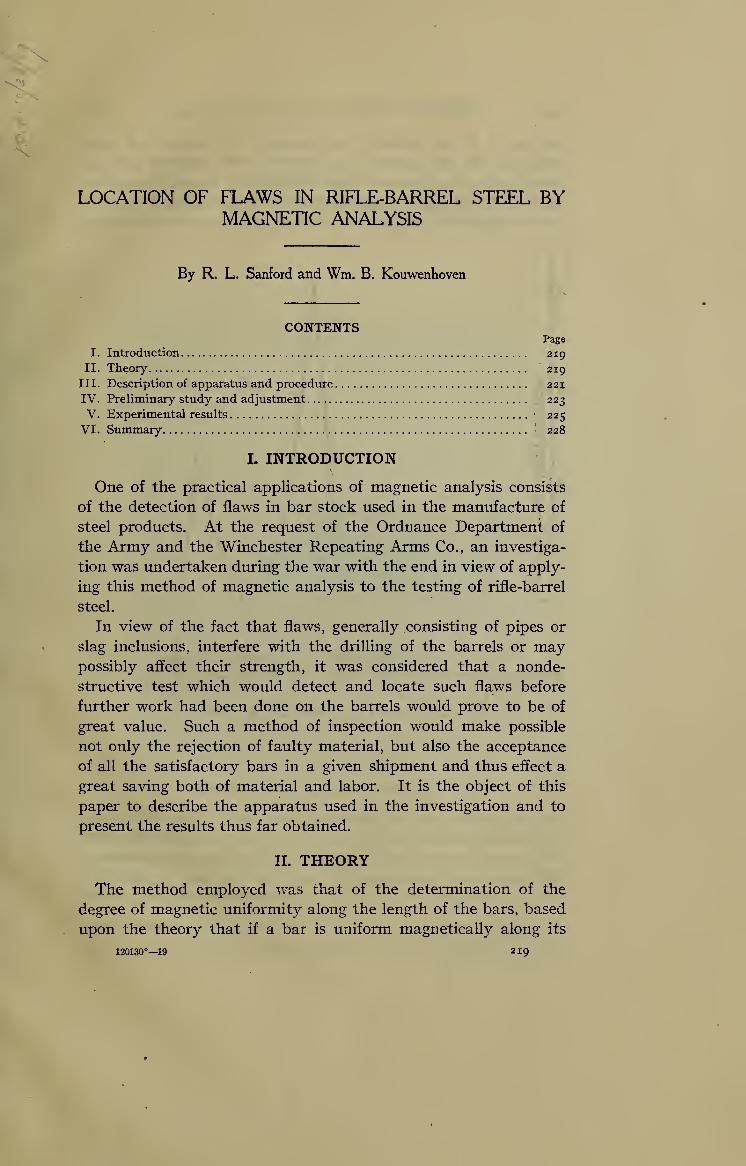
I. INTRODUCTION
One of the practical applications of magnetic analysis consists
of the detection of flaws in bar stock used in the manufacture of
steel products. At the request of the Ordnance Department of
the Army and the Winchester Repeating Arms Co., an investiga-
tion was undertaken dtnring the war with the end in view of apply-
ing this method of magnetic analysis to the testing of rifle-barrel
steel.
In view of the fact that flaws, generally consisting of pipes or
slag inclusions, interfere with the drilling of the barrels or maypossibly affect their strength, it was considered that a nonde-
structive test which would detect and locate such flaws before
further work had been done on the barrels would prove to be of
great value. Such a method of inspection would make possible
not only the rejection of faulty material, but also the acceptance
of all the satisfactory bars in a given shipment and thus effect a
great saving both of material and labor. It is the object of this
paper to describe the apparatus used in the investigation and to
present the results thus far obtained.
II. THEORY
The method employed was that of the determination of the
degree of magnetic uniformity along the length of the bars, based
upon the theory that if a bar is uniform magnetically along its
120130°—19 219
220 Scientific Papers of the Bureau of Standards [Vol. IS
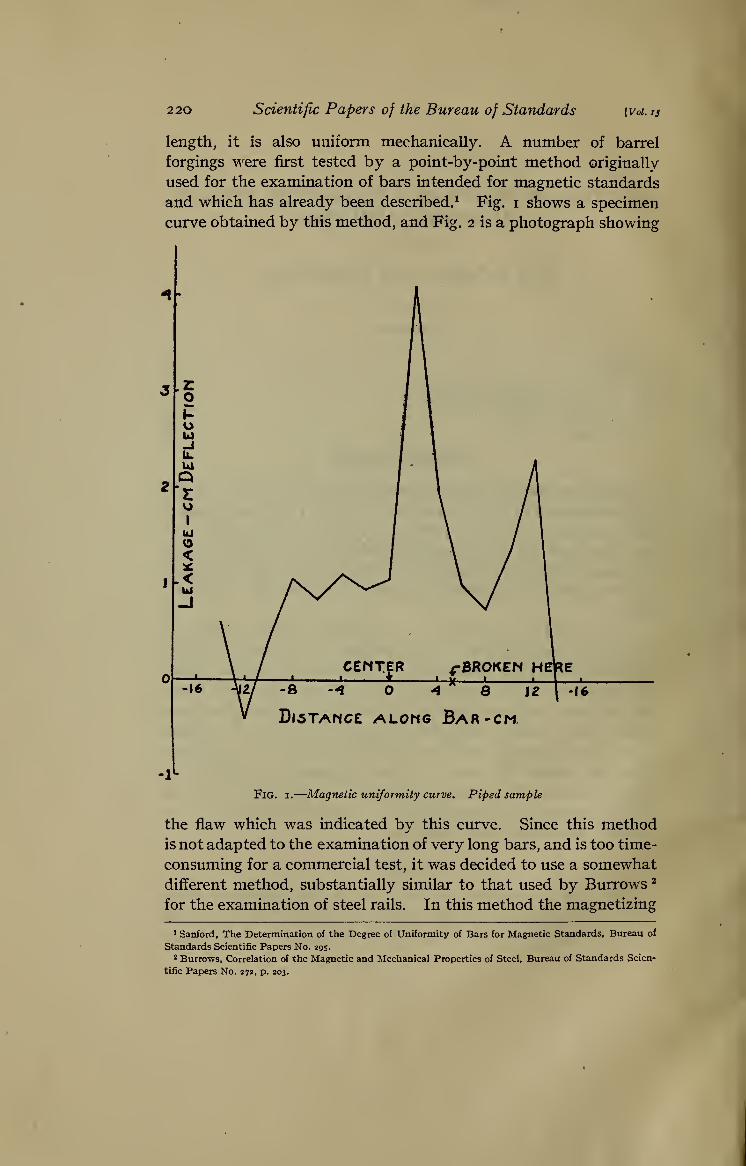
length, it is also uniform mechanically. A number of barrel
forgings were first tested by a point-by-point method originally
used for the examination of bars intended for magnetic standards
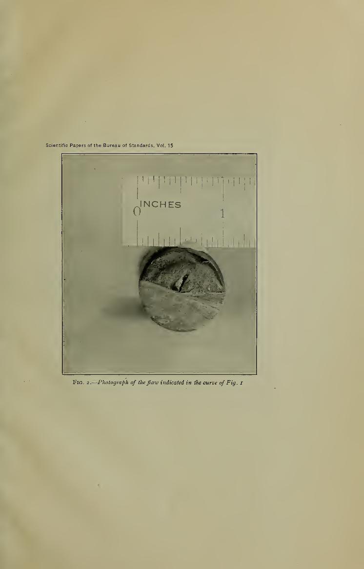
and which has already been described.^ Fig. i shows a specimen
curve obtained by this method, and Fig. 2 is a photograph showing
-S -^ O 4 8 12
Di5Tamc£ along Bar-cm
Fig. I.
—
Magnetic uniformity curve. Piped sample
the flaw which was indicated by this ctirve. Since this methodis not adapted to the examination of very long bars, and is too time-
consuming for a commercial test, it was decided to use a somewhatdifferent method, substantially similar to that used by Burrows ^
for the examination of steel rails. In this method the magnetizing
Sanford, The Determination of the Degree of Uniformity of Bars for Magnetic Standards, Bureau of
Standards Scientific Papers No. 295.
* Burrows, Correlation of the Magnetic and Mechanical Properties of Steel, Bureau of Standards Scien-
tific Papers No. 272, p. 203.
Scientific Papers of the Bureau of Standards, Vol. 15
Fig. 2.
—
Photograph of the flaw indicated in the curve of Fig. I
Scientific Papers of the Bureau of Standards, Vol. 15
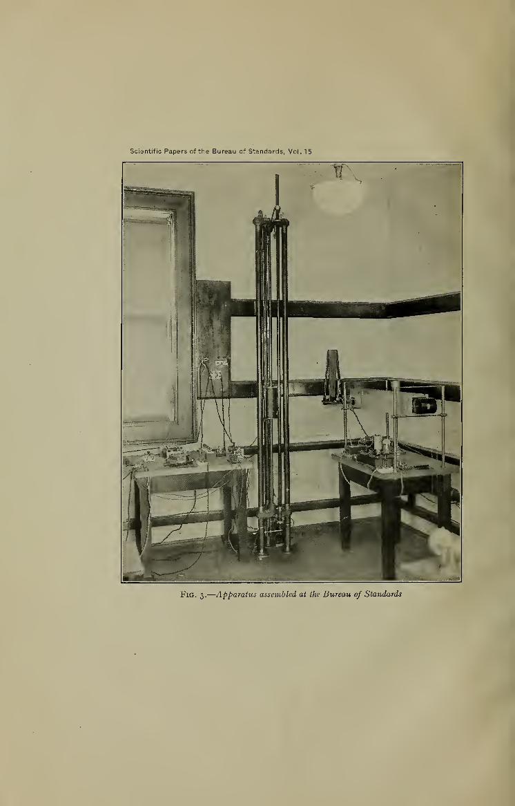
Fig. 3.
—
Apparaiuj a^^cniblcd at the Bureau of Standards
^^wmkrven] Magnetic Analysis of Rifle-Barrel Steel 221
force is applied by means of a solenoid which surrounds the bar
and travels along its length. Mounted within this magnetizing
solenoid is a test coil by means of which variations in magnetic
flux within the bar can be measured. If the bar is magnetically
uniform along its length its permeabiHty is constant for a given
magnetizing force and the magnetic flux at each point as the
solenoid is moving along is constant. If this is the case, there
will be no electromotive force induced in the test coil as the solenoid
travels the length of the bar. If, on the other hand, the permea-
bility is not constant, the flux will vary and a corresponding
electromotive force will be induced in the test coil which, if the
coils are moved at a constant speed along the bar, is proportional
to the change in flux. If, instead of using a single test coil in the
manner just described, we use two test coils connected in series
opposition we obtain a result that is practically not affected bysUght variations in the magnetizing current during a run, as anyvariations in flux linked with one coil is neutralized by correspond-
ing changes in the other.
III. DESCRIPTION OF APPARATUS AND PROCEDURE
Fig. 3 is a photograph of the apparatus as set up at the Bureau
of Standards for preliminary experiments before it was taken to
the Winchester plant at New Haven for test under factory con-
ditions. The bar to be examined is clamped at the centers of two
triangular end plates of cast iron. These end plates are sup-
ported by three wrought-iron pipes which also constitute the
return circuit for the magnetic flux induced in the test bar. Themagnetizing solenoid, which is shown in more detail in Fig. 4,
is supported between the pipes by means of cords running over
pulleys and carrying counterweights which hang inside the sup-
porting pipes. One of these cords is continuous and mns over a
drum mounted on the shaft of a small electric motor. By meansof this arrangement the coils can be run up and down along the
length of the bar. Magnetizing current is suppUed to the solenoid
by means of a storage battery and regulated by means of sliding
rheostats. The guiding rollers shown in Fig. 4 were later arranged
to bear on the test bar instead of on the iron pipes, as it wasfound that many of the bars we're not straight. The test coils
are mounted on a separate tube and their position is adjustable.
These test coils have 500 turns each, and are connected through
suitable resistances to the galvanometer shown at the right of the
222 Scientific Papers of the Bureau of Standards [Voi. 15
apparatus in the photograph. Deflections of the galvanometerare observed by means of a spot of Hght reflected from its mirror
onto a ground-glass scale. Permanent records of these deflec-
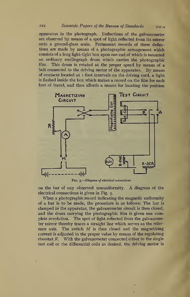
tions are made by means of a photographic arrangement whichconsists of a long light-tight box upon one end of which is moimtedan ordinary oscillograph drum which carries the photographicfilm. This drum is rotated at the proper speed by means of abelt connected to the driving motor of the apparatus. By meansof contacts located at i-foot intervals on the driving cord, a light
is flashed inside the box which makes a record on the film for eachfoot of travel, and thus affords a means for locating the position
ma6metizim6Circuit
Test Circuit
Fig. 5.
—
Diagram of electrical connections
on the bar of any observed nonuniformity. A diagram of the
electrical connections is given in Fig. 5.
When a photographic record indicating the magnetic uniformity
of a bar is to be made, the procedure is as follows: The bar is
clamped in the apparatus, the galvanometer circuit is then closed,
and the drum carrying the photographic film is given one com-
plete revolution. The spot of light reflected from the galvanome-
ter mirror thereby traces a straight line which serves as the refer-
ence axis. The switch M is then closed and the magnetizing
current is adjusted to the proper value by means of the regulating
rheostat R. With the galvanometer connected either to the single
test coil or the differential coils as desired, the driving motor is
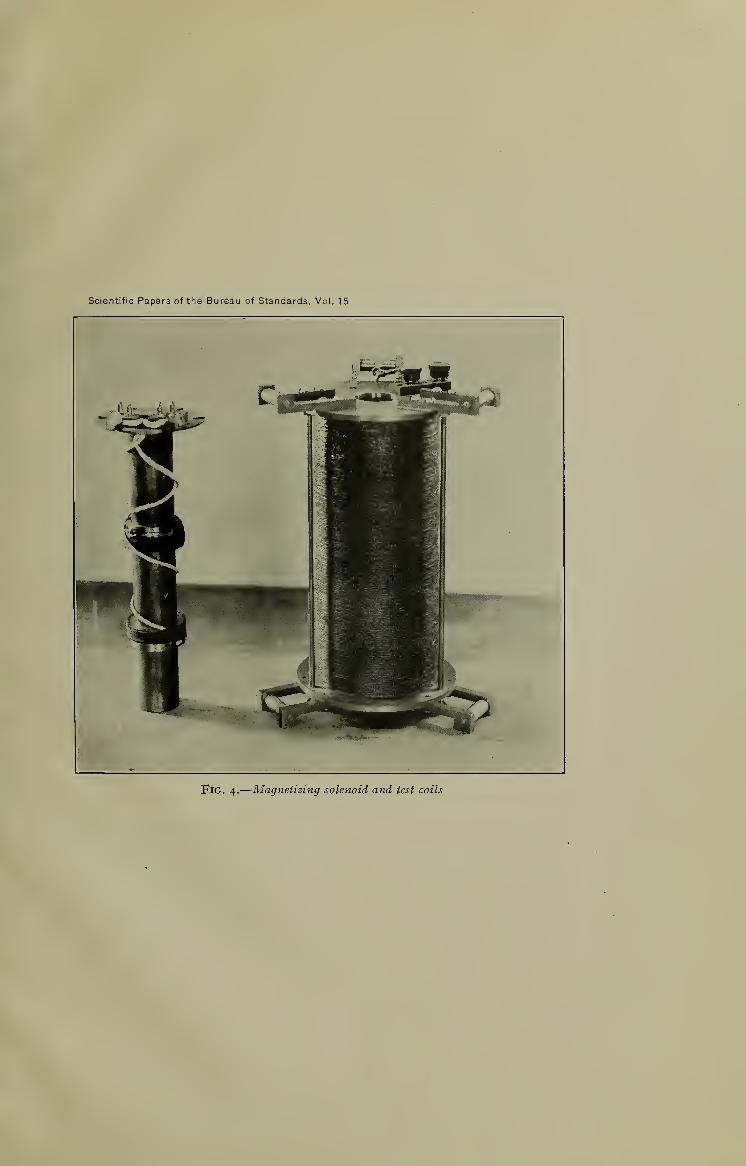
Scientific Papers of the Bureau of Standards, Vol. 15
Fig. 4.
—
Magnetizing solenoid and test coils
Sanford TKouwenhaveni Magnetic Analysis of Rifle-Barrel Steel 223
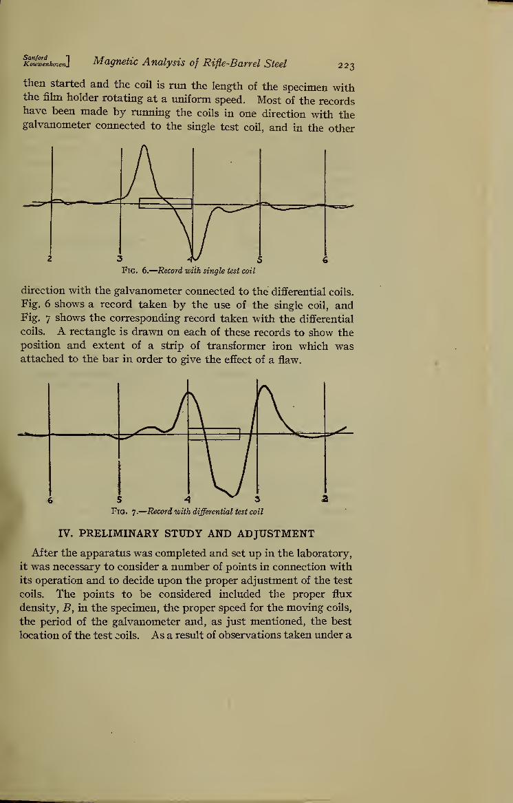
then started and the coil is run the length of the specimen withthe fihn holder rotating at a uniform speed. Most of the recordshave been made by running the coils in one direction with thegalvanometer connected to the single test coil, and in the other
3 -(V 5Fig. 6.—Record with single test coil
direction with the galvanometer connected to the differential coils.
Fig. 6 shows a record taken by the use of the single coil, andFig. 7 shows the corresponding record taken with the differential
coils. A rectangle is drawn on each of these records to show the
position and extent of a strip of transformer iron which wasattached to the bar in order to give the effect of a flaw.
Fig. 7.
—
Record with differential test coil
IV. PRELIMINARY STUDY AND ADJUSTMENT
After the apparatus was completed and set up in the laboratory,
it was necessary to consider a number of points in connection with
its operation and to decide upon the proper adjustment of the test
coils. The points to be considered included the proper flux
density, B, in the specimen, the proper speed for the moving coils,
the period of the galvanometer and, as just mentioned, the best
location of the test coils. As a result of observations taken under a
224 Scientific Papers of the Bureau of Standards [Voi. ts
great variety of conditions, it was found that a flux density of
approximately 15 000 gausses gives the best results. The speed
of travel finally adopted was approximately X foot per second.
It is necessary in order to insure that the record gives a true indi-
cation of the condition of the specimens that the galvanometer
have a fairly short period. If the period is too long, the galvanome-
ter does not follow closely the changes in the induced electromotive
force. A period of approximately one second was found to be
satisfactory. The photograph of the test coils shows only two coils
in position. For convenience, however, a third coil was made,
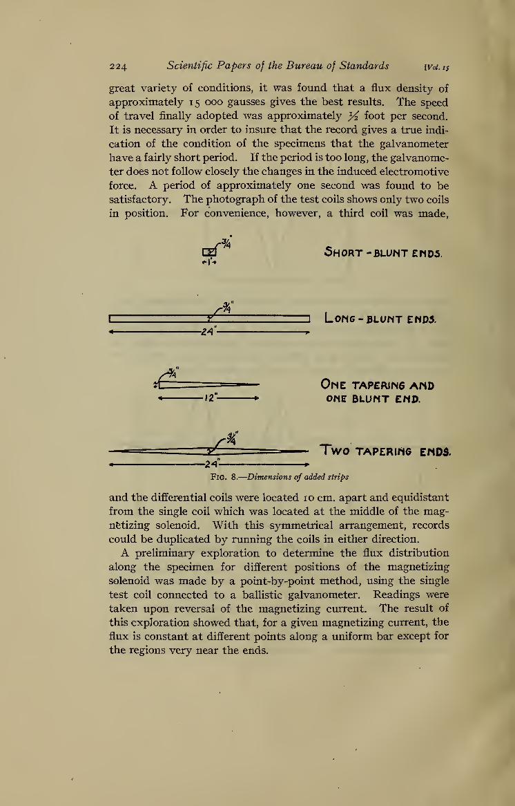
CeT 5hORT -BLUNT Eh 05.
y' LONG-BLUMT ENOA
-^4" ,
One TAPEWN6 AND12" ONE BLUNT END.
^ Two TAPERIrtO EMD5.„ 2A »
Fig. 8.
—
Dimensions of added strips
and the differential coils were located 10 cm. apart and equidistant
from the single coil which was located at the middle of the mag-netizing solenoid. With this symmetrical arrangement, records
could be duplicated by running the coils in either direction.
A preliminary exploration to determine the flux distribution
along the specimen for different positions of the magnetizing
solenoid was made by a point-by-point method, using the single
test coil connected to a ballistic galvanometer. Readings were
taken upon reversal of the magnetizing cturent. The result of
this exploration showed that, for a given magnetizing current, the
flux is constant at different points along a uniform bar except for
the regions very near the ends.

fc^wfnhaven] Magnetic Analysis of Rifle-Barrel Steel 225
In order to study the effect of flaws varying in extent and kind,
a number of records were made on a bar previously found to be
uniform, to which were attached strips of transformer steel of
various shapes and sizes. This procedure was necessary, because
of the difficulty of producing longitudinal flaws by artificial means.
Fig. 8 shows the shapes and dimensions of the strips thus used.
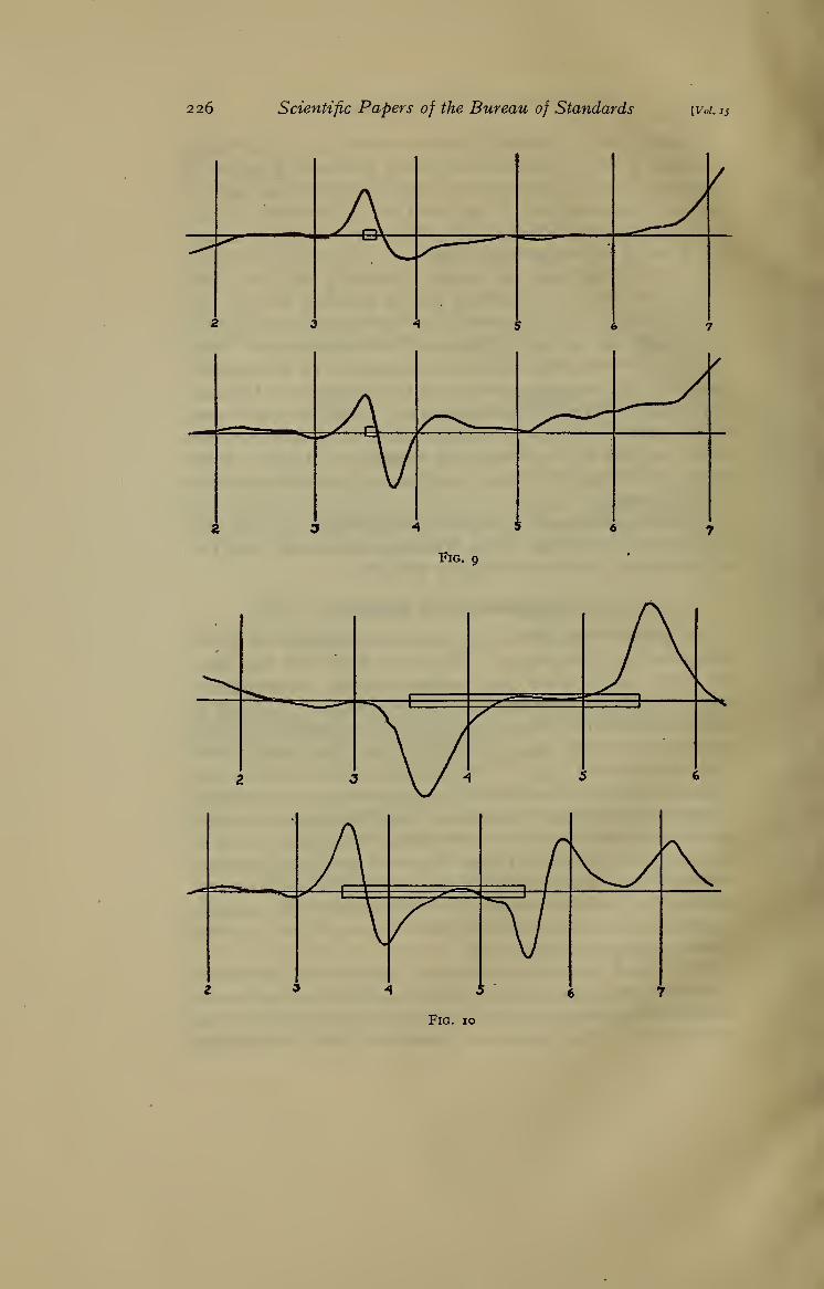
Figs. 9 to 12, inclusive, are records obtained in this way. Thelocation and shape of the added strip is indicated in each case
upon the record. The figures show records taken both by means
of the single test coil and by means of the differential coils. Figs.
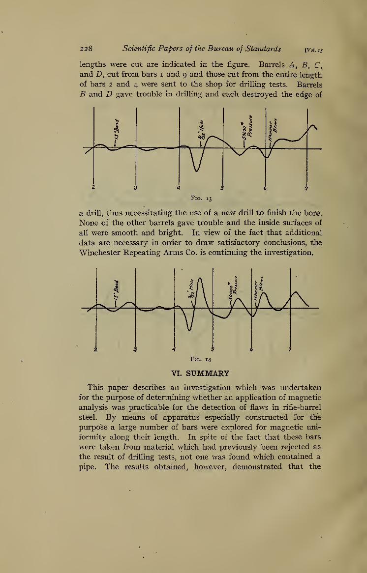
13 and 14 show the effect of various treatments on a bar originally
uniform. The treatments given, and the locations, are indicated
in the figures. It was at first feared that, due to the sensitiveness
of the method, spm-ious indications would be obtained for bars
which had been slightly bent during shipment and handling at the
factory. The result of this last test, however, indicates that such
is not the case.
After the preliminary experiments just described, the apparatus
was shipped to the plant of the Winchester Repeating Arms Co.,
at New Haven, and there set up for final trial.
V. EXPERIMENTAL RESULTS
The greatest difficulty in this line of investigation lies in the
interpretation of the results. This is due to the fact that there
are many causes which may produce magnetic inhomogeneity
and it is difficult to differentiate between them. The work at
New Haven was done with the end in view of obtaining data which
would establish the amount of variation and the type of curve
which accompanies a pipe. The procedure was to make records
of bars which in a preliminary test showed large variations.
These bars were chosen from lots of steel which had previously
been rejected as the result of tests in the drilling shop. It is aninteresting fact that even though this lot of steel had previously
been rejected on account of pipes, not a single pipe was discovered
in the drilling tests on samples for which records of the magnetic
uniformity had been obtained. This is true of all the steel
examined up to March 31, 191 9.
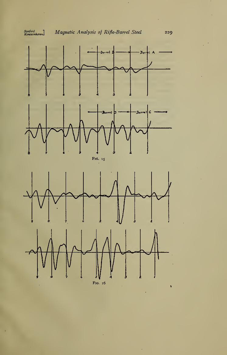
Figs. 15 and 16 show records of the degree of magnetic homo-geneity of four bars of steel. These records were made with
the differential test coils and with a fairly low sensitivity of the
galvanometer. The portions of these bars from which barrel
226 Scientific Papers of the Bureau of Standards [Voi.15

K^ZLhmet] Magnetic Analysis of Rifle-Barrel Steel 227
228 Scientific Papers of the Bureau of Standards {Vol. IS
lengths were cut are indicated in the figure. Barrels A, B, C,
and D, cut from bars i and 9 and those cut from the entire length
of bars 2 and 4 were sent to the shop for drilling tests. Barrels
B and D gave trouble in drilling and each destroyed the edge of
Fig. 13
a drill, thus necessitating the use of a new drill to finish the bore.
None of the other barrels gave trouble and the inside surfaces of
all were smooth and bright. In view of the fact that additional
data are necessary in order to draw satisfactory conclusions, the
Winchester Repeating Arms Co. is continuing the investigation.
Fig. 14
VI. SUMMARY
This paper describes an investigation which was undertaken
for the ptupose of determining whether an application of magnetic
analysis was practicable for the detection of flaws in rifle-barrel
steel. By means of apparatus especially constructed for thie
purpose a large ntunber of bars were explored for magnetic uni-
formity along their length. In spite of the fact that these bars
were taken from material which had previously been rejected as
the result of drilling tests, not one was found which contained a
pipe. The results obtained, however, demonstrated that the
IcMwLhoveiJiMagnetic Analysis of Rifle-Barrel Steel 229
n ..11 ^
1 ^/> /"V—- ^^^ '^y^ . . -^
•
< A h i.
230 Scientific Papers of the Bureau of Standards [Voi. 15
method is amply sensitive to detect and locate flaws. Fm*ther
study is necessary to determine to what degree the sensitivity of
the apparatus should be reduced in order not to cause the rejection
of material which is satisfactory for all practical purposes, and
also to determine the type and magnitude of the effect which will
be produced by a pipe. For this reason the work is being con-
tinued by the Winchester Repeating Arms Co., who cooperated in
the investigation and at whose plant the apparatus has been
installed.
The authors wish to take this opportunity to acknowledge
their indebtedness to J. S. Gravely, M. F. Fischer, and J. S.
Becker for their valuable assistance in carrying out this investi-
gation.
Washington, April 14, 191 9.
LIBRARY OF CONGRESS
020 367 878 2