lmfbr structural materials and design engineering (uc-79h
TRANSCRIPT

Distribution Category:LMFBR Structural Materials and
Design Engineering (UC-79h)
ANL-78-74
ARGONNE NATIONAL LABORATORY9700 South Cass AvenueArgonne, Illinois 60439
METALLOGRAPHIC AND FRACTOGRAPHIC OBSERVATIONSOF POSTTEST CREEP-FATIGUE SPECIMENS
OF WELD-DEPOSITED TYPE 308 CRE STAINLESS STEEL
by
M. W. Williams*
Materials Science Division
qTinsd ty em Wimi Srwr wumfhsL yhih.olWiuaad by 06 am paw U i s . NOW
ENV. am my of 6w.up0a1Wi am my of"
cmuacIU, o SKWIo o. or tb mphy*)i. mkmMywesqt. upau a1u t4 of mn my -p
bwi of ormbop'ifos em .gy. .o"mpbtaw fwwm of my Ioiatb. app' ' p1044K'of
poms 44~. or upuunaS ei mn- ' -s
adsrphr.Wdy0vWd iIs.
August 1978
( , t I '
*Mechanical Engineering Department, Western Michigan University,Kalamasoo, Michigan 49008
... "
. ; a


3
TABLE OF CONTENTS
Pag&e
ABSTRACT................... . . 5
1. INTRODUCTION................. . . 5
II. EXPERIMENTAL PROCEDURE................................5
III. RESULTS . . . . . ... 7.............7
IV. DISCUSSION... . . ..... ................................ 15
V. CONCLUSIONS....... . ... .... ...... .. .. ...... . . .. . 16
ACKNOWLEDGMENTS. . . . ......................... ..... 16
REFERENCES........... . ........... .................... 17

4
LIST OF FIGURES
No. Title Page
1. SMA Type 308 CRE Stainless Steel Weld Metal Test Specimens.. . 6
2. Microstructure of SMA Type 308 CRE Stainless Steel WeldM eta.l.......................................... 8
3. Microstructure of Specimen CE89L12.................... . . . 8
4. Microstructure of Specimen CE36L1 . .. .... ... .... . ...... 8
5. Secondary Crack at Fracture Surface of Specimen CE36L3...... ... 9
6. Secondary Cracks at Fracture Surface of Specimen CE89TS1. ... 9
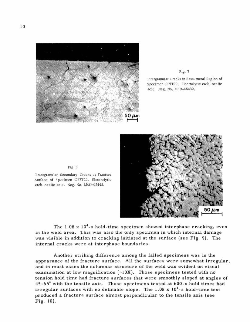
7. Intergranular Cracks in Base-metal Region of Specimen CE7T22 . 10
8. Transgranular Secondary Cracks at Fracture Surface of
Specimen CE7T22.. . . . . . . . . . . . . . . . . . ... . . . . .. . . .. . 10
9. Crack at Surface of Gauge Section and Internal Cracking inSpecimen CE36L1 . . . . . .. . .. . .. .. .. .. . . . . .. .. . . . . . 11
10. SEM Macrographs of Fracture Surfaces of Test Specimens. . . . . 11
11. Crack Length vs Number of Cycles for Specimen CE87TC. . . . . . 12
12. SEM Fractograph of Specimen CE87TC Showing a Portion of the
Fatigue Striations . . . . . . . . . . . .. . .. . . .. . . .. . . . . . . . . . 12
13. SEM Fractograph Specimen CE87TC Showing Ductile Tearing inFast-fracture Region-..-..-....................-.-.... . ... 13
14. SEM Fractograph of Specimen CE89L12 Showing FatigueStriations and Ductile Tearing in Fast-fracture Region... . . .. . 13
15. SEM Fractograph of Specimen CE36L3.... . . ..... . .......... 13
16. SEM Fractograph of Specimen CE7T22............ ...... . 14
17. SEM Fractographs of Specimen CE36LI. .. .. ........ ....... 14
LIST OF TABLES
No. Title Pae
I. Chemical Analysis of Type 308 CRE Weld Metal..... . . .... . 6
II. Specimens, Test Conditions, and Failure Times................. 7

5
METALLOGRAPHIC AND FRACTOGRAPHIC OBSERVATIONSOF POSTTEST CREEP-FATIGUE SPECIMENS
OF WELD-DEPOSITED TYPE 308 CRE STAINLESS STEEL
by
M. W. Williams
ABSTRACT
Type 308 CRE stainless steel weld specimens weresubjected to metallographic and fractographic analysis afterfailure in elevated-temperature (593 C) creep-fatigue tests.The failure mode for specimens tested under continuous-cyclefatigue conditions was predominantly transgranular. When thetest cycle was modified to include a hold time at the maximumtensile strain, the failure mode became predominantly inter-phase. Sigma phase was observed within the delta-ferriteregions in the weld. However, the presence of sigma phase didnot appear to affect the failure mode.
I. INTRODUCTION
Type 308 stainless steel weld metal with controlled residual elements(CRE's)' is used to join Type 304 austenitic stainless steels. These materialsare under investigation to determine their suitability for use in the mainsteam piping and reactor vessels in power-generation plants associated withthe Liquid Metal Fast Breeder Reactor (LMFBR) program. In the presentinvestigation, specimens of different orientations and locations within asingle weld were subjected to elevated-temperature X593C) low-cycle fatiguetesting with various tension hold times and two different fully reversed totalstrain ranges. The intent was to characterize the failure mode and to correlatethat mode with the test conditions and with microstructural changes. Theresults indicate that transgranular failure occurs under low-cycle fatigueconditions. However, if the test cycle is modified to include a hold time atthe maximum tensile strain, the failure results from interphase separation.
II. EXPERIMENTAL PROCEDURE
Specimens for fatigue testing are from a single shielded-metal-arc(SMA) weld produced by Combustion Engineering. The double U-grooveweld joined two Type 304 stainless steel base-metal plates that were 60 mmthick. The weld required approximately 40 passes to complete. Chemical

6
analysis of the weld metal is given in Table I. The weld was sectioned andmachined into specimens with 5.08-mm-dia gauge sections. Specimens bothlongitudinal and transverse with respect to the weld were produced from the
center, surface, and an intermediate location within the weld (see Fig. 1).The surface of the gauge section w:i polished to reduce crack initiation at
surface scratches. All specimens were aged in argon for 3.6 x 10⁶ s at593 C before fatigue testing.
TABLE I. Chemical Analysis of Type 308 CRE Weld Metal
Element wt % Element wt oC 0.051 Nb + Ta <0.01Mn 1.87 Ti 0.06P 0.042 Co 0.07S 0.009 Cu 0.17Si 0.60 B 0.007Cr 20.10 V 0.10Ni 10.14 N 0.042Mo 0.24
La
LC
lot LONGITUDINAL sPCCIucNS
Fig. 1
SMA Type 308 CRE Stainless Steel Weld MetalTest Specimens. All dimensions are in mm.Neg. No. MSD-64600.
(0) TRANSVSE SPIC1IINS
".e-14 T0S-20.. 1 *
IiI4R
5.00 DIA AT iTAPER TO 0.10DIA AT ENDS OPAUE SECTiON
(61 SPECIMEN METALS
4
9

7
The apparatus for fatigue testing is described in detail in Ref. 2.Specimens were tested in air at 5930C. The temperature, maintained byinduction heating, was uniform to 4*C over the entire gauge section. Strainrates were contant at 4 x 10⁻³ s-'. Tests were strain-controlled with maximumstrains of 0.25 or 0.50% both in tension and compression (act = 0.50 or 1.00%).Hold times of 0, 600, or 1.08 x 10⁴ s at the maximurn tensile strain were used.Because previous investigations of wrought Typa 304 stainless steel3 havedemonstrated the greater influence of tensile hold time on failure mode, nocompressive hold times were used. Table II lists the test conditions andfailure times for the specimens examined in the present investigation.
TABLE IU. Specimens, Test Conditions, and Failure Times
LocationSpecimen and Strain Range Tension Hold Cycles to Time toNumber Orientationa Aet, % Time, s Failure, N Failure, s
CE7LI LS 1.00 0 9102 4.55 x 10⁴CE36LI LS 1.00 1.08 x 10⁴ 1403 1.51 x 10⁷CE36L3 LC 1.00 6.0 x 10 1944 1.18 x 10⁶CE7T22 TI 1.00 6.0 x 10² 1288 7.78 x 10CE89TS1 TS 0.50 0 11,996 3.00 x 10⁴CE89L12 LI 0.50 0 35,716 8.92 x 10⁴CE89TS2 TS 1.00 0 2441 1.22 x 10CE87TC TC 1.00 0 1709 8.53 x 10³
aSee Fig. I for nomenclature.
After failure of the weld specimens, the fracture surfaces wereexamined both optically and by scanning-electron microscopy. In addition,the specimens were examined metallographically to reveal microstructuralfeatures and any secondary cracking that may have occurred on the surfaceof the gauge section or on the fracture surface.
III. RESULTS
The microstructure of the weld area is shown in Fig. 2. The primaryaustenite phase is separated into long columnar regions by the secondarydelta-ferrite phase. Higher magnification (see Fig. 3) shows the secondaryferrite region with carbide precipitates at the interphase boundaries asidentified by previous investigators. 4 In another specimen (Fi. 4), theformation of sigma phase within the ferrite region is apparent. The trans-formation of delta ferrite to sigma phase was most complete in the longest-lived test specimen. However, the extent of the transformation was notuniform in any of the specimens, and islands of sigma phase were evident,even in the specimens with the shortest test periods.

3.
3 2
(a)
- ''
fi.A 1
-i
, 200
- ' 200 pm
(c)
Fig. 2
Microstructure of SMA Type 308 CRE(b) Stainless Steel Weld Metal. Electrolytic
etch, 1010 oxalic acid. (a) Coordinateaxes; (b) parallel to 2-3 plane;(c) parallel to 3-1 plane; (d) parallelto 1-2 plane. Neg. No. MSP-G4599.
(d)
~'
-
Fig. :3
Microstructure of Specimen (E89L12.Murakami' s reagent. Secondary ferritephase (6) decorated with carbides (c) isvisible. Neg. No. MSD-65444.
/
YAM
I .
y*1
'ar
" . 4 1
L~~
Fig. 4
Microstructure of Specimen CE36L1. Murakami'sreagent. Secondary ferrite phase (6) has under-gone partial transformation to sigma phase (o).Sonic phase-boundary carbides (c) are stillvisible. Neg. No. MSI-6;5435.
8
w}7
;:,. n
d f
10 /Irn
.

9
Further substantiation of the presence of sigma phase was sought
through magnetic etching.5 All specimens contained a ferromagnetic phase(delta ferrite). The ferrite phase appeared discontinuous when observed by
the magnetic-etching technique. Presumably. the ferrite regions are sepa-
rated by the growing sigma phase. These microstructural changes are consis-
tent with those observed in earlier studies of Type 308 CRE stainless steelweld metal.4 5
Metallographic investigation of secondary cracking of the test spec-imens showed some correlation with the amount of tension hold time in the
fatigue test. Specimens tested at 0- or 600-s hold times had secondary
cracks both at the fracture surface and at the surface of the gauge sectionwhich propagated predominantly in a transgranular fashion (as shown in
Figs. 5 and 6). Cracks appeared to initiate at interphase boundaries. One
transverse specimen (CE7T2U), which contained some base metal within the
gauge section, clearly showed cracking at the grain boundaries in the base
metal, but transgranular cracking in the weld area (see Figs. 7 and 8).
1 . . / .. .4
Fig., 6
Secondary cracks at Fr.icturc surfaceof Specimen CI.91'S1. Murakani'sreagent. Neg. No. MISD-65433.
',,c riklarv ( rick( it Ir.iltdire 'ailrt.wc of' ilpv fmi (n r i) '2rI'ni' c wt
A
.-
* . 4, K .
,. r
-7-
~~5 m
Fig. 8
Transgranular Secondary Cracks at FractureSurface of Specimen CE7T22. Electrolyticetch, oxalic acid. Neg. No. MSD-65445.
Fig. 7
lntergranular Cracks in Base-metal Region ofSpecimen CE7T22. Electrolytic etch, oxalicacid. Neg. No. MSD-65432.
of/
y 'S) 1 si
-4 4
S50.m
The 1.08 x 10-s hold-time specimen showed interphase cracking, even
in the weld area. This was also the only specimen in which internal damage
was visible in addition to cracking initiated at the surface (see Fig. 9). The
internal cracks were at interphase boundaries.
Another striking difference among the failed specimens was in the
appearance of the fracture surface. All the surfaces were somewhat irregular,
and in most cases the columnar structure of the weld was evident on visual
examination at low magnification (~IOX). Those specimens tested with notension hold time had fracture surfaces that were smoothly sloped at angles of
45-65* with the tensile axis. Those specimens tested at 600-s hold times had
irregular surfaces with no definable slope. The 1.08 x 10 4 - s hold-time test
produced a fracture surface almost perpendicular to the tensile axis (seeFig. 10).
10

I
- r
s-.'I
-I "
C
50 Lm
Fig. 9. Crack at Surface of Gauge Section and InternalCracking in Specimen CE36L1. Murakami'sreagent. Neg. No. MSD-G5446.
- -
(H --....---.
v4...
A. "" "
. U#1 "
1 I
"~~ -: .. ". AI:
"", !. Jja ""
Fig. 10
S i M Macrographs of Fracture Surfaces of Test Speci-mens. W indicates weld-solidification direction; I in-dicates initiation site. (a) C:87TC (no tension holdtime); (b) CE7T2. (G00-s tension hold time); (c) CE3;1.1(1.08 x 10'l- tCMitII hold lime P. N1. . No. '~- -
1 mm
1

12
The difference among failure modes for different tension hold timeswas further exhibited by the appearance of the fracture surface at highermagnifications. Striations typical of ductile fatigue failure were visible on
the fracture surface of the zero-hold-time specimens. Ductile tearing wasalso evident in the fast-fracture region of these surfaces. In one specimen
(CE87TC), a continuous series of about 600 striations with spacings of0.8-30 pm was visible over -2 mm. Figure 11 shows the dependence of crack
length on the number of test cycles. The orientation of the propagating crackfront bore no discernible relationship to the solidification direction of theweld (see Figs. 12 and 13). Less extensive series of striations could be seenin all the other zero-hold-time specimens (see Fig. 14). Striations were also
visible in the 600-s hold-time specimens. However, their appearance wasless regular and they were frequently separated by surface cracks (as shownin Figs. 15 and 16).
1100 1200 1300 1400
CYCLES
Fig. 11
Crack Length vs Number of Cycles for Speci-men CE87TC. Neg. No. MSD-65479.
1500 1600 1700
SEM Fractograph of Specimun Cim'7TC (No
Tension Hold Time) Showing a Portion ofthe Fatigue Striations. Crack-propagationdirection is toward the lower right. Weld-solidification direction is approximately.vertical. Neg. No. MSD-05436.
2000
1500
1000
S800
600
W 500
400
U 300
200k
-I 70
- o -000 -
-0
0
OO
0000
0- 0
0

13
Fig. 13
SEM Fractograph Specimen CE87TC (No Ten-sion Hold Time) Showing Ductile Tearing inFast-fracture Region. Neg. No. MSD-65437.
f. ~ ~ ~ ~ 1 y .e r
Fig. 14
SEM Fractograph of Specimen CE89L12 (NoTension Hold Time) Showing Fatigue Stria-tions (Upper Left) and Ductile Tearing inFast-fracture Region (Lower Right). Neg.No. MSD-65438. t _
Fig. 15
SEM Fractograph of Specimen CE36L3 (600-sTension Hold Time). Irregular striations andsecondary cracks are visible. Neg.No. MSD-65439.

14
Fig. 1b4 ,SEM Fractograph of Specimen CE7T22 (600-s Ten-sion Hold Time). Irregular striations and secondarycracks are visible. Neg. No. MSD-65440.
In contrast to the above behavior, the 1.08 x 10 4 -s hold-time specimen(CE36L1) exhibited few striations. Considerable secondary cracking 'was noted
on the fracture surface, and the few striations visible were very irregular and
were frequently separated by secondary cracks (shown in Fig. 17a). Portionsof the fracture surface clearly showed interphase separation (see Fig. 17b).
Much of the fracture surface was featureless (see Fig. 17c).
(a) (b)
Fig. 17
SEM Fractographs of Specimen CE36L1 (1.08 x 10⁴-sTension Hold Time). (a) Irregular striations andsecondary cracks; (b) interphase separation; (c) fea-tureless region near center of fracture surface. Neg.Nos. MSD-65441, -65442, and -65443.
-C
(c)

15
An energy-dispersive X-ray spectrum from regions on opposite sidesof a secondary crack on the fracture surface of the same specimen showed
different relative amounts of iron and chromium, indicating different phases
in the two regions. An X-ray spectrum from two sides of a secondary crack
on the polished surface of the same specimen mounted for metallographyyielded similar results.
IV. DISCUSSION
The results of this investigation show that the failure mode of Type 308CRE weld specimens is predominantly transgranular in specimens subjectedto low-cycle fatigue testing with no tensile hold time. When the test conditions
are altered to include a hold time at the maximum tensile strain, the crackpropagation becomes predominantly interphase.
These results should be compared with two previous investigations. A
study, similar to the present one, of 16-8-2 stainless steel weld metal alsoshowed a change in failure mode from transgranular to interphase separation
when a tensile hold time was added to the fatigue test cycle.6 However,
elevated -temperature creep testing of Type 308 weld metal both with and
without CRE resulted in interphase separation in the standard weld metal, but
predominantly transgranular shear failure in the CRE weld metal.7 Whereinterphase separation was observed, it occurred along sigma-phase/austeniteboundaries. The latter investigators also observed crack propagation through
sigma particles.4 In the present investigation, crack propagation throughsigma particles was not seen. Nor was it possible, because of the finenessof the microstructure, to be certain whether intergranular cracking occurred
through the secondary phase (sigma or delta ferrite) or between the austeniteand the secondary phase.
In the present investigation, interphase separation occurred in thespecimen with the longest test time (measured in seconds, not cycles). Thatspecimen also had the most extensive sigma-phase formation. The correla-tion of sigma-phase formation with the change in failure mode suggests thatthe microstructural changes might be the cause of the transition from trans-granular to interphase cracking. That is unlikely to be the case, however,because in the shorter-lived test specimens, even in regions with extensivesigma-phase formation, the propagating crack showed essentially no interactionwith the sigma phase. Thus, the increased development of sigma phase in thelongest hold-time specimen apparently cannot be the principal reason for thechange in failure mode.
Another possibility is that the age of the b specimens, rather than thenature of the strain cycle, is the determinant of the failure mode. Somechanges, possibly atmospheric effects or segregation at the interphaseboundaries, may be occurring undetected by the techniques used in the present

16
investigation. The specimens tested at the 0.50% strain range had longerlifetimes than those tested at the 1.00% strain range. The failure modes
under the two strain ranges were not observed to be different. However, the
times to failure were not extended as much by reduction of the strain from
1.00 to 0.50% as by the addition of the tension hold time. Studies by Chengand Diercks 3 and by Majumdar and Maiya8 on wrought Type 304 stainlesssteel showed correlation of the failure mode with the nature of the test cycle,
rather than with the duration of test. That evidence, together with the micro-
structural observations in the present investigation, indicates that it is indeed
the addition of the tension hold time, rather than changes caused by aging,
that results in the alteration in fracture characteristics.
V. CONCLUSIONS
The failure mode of Type 308 CRE weldments under elevated-temperature
creep-fatigue conditions depends on the duration of the tension hold time.
Under low-cycle fatigue testing with no tension hold time, the failure mode ispredominantly transgranular. As the tension hold time is increased, interphasecrack propagation predominates. This change in failure mode occurs coinci-dentally with the formation of sigma phase within the delta-ferrite regions.However, the absence of interaction between the propagating crack and thesigma phase indicates that the presence of the sigma phase cannot be theprincipal reason for the change in failure mode with increasing tension holdtime.
ACKNOWLEDGMENTS
I wish to express my thanks to D. T. Raske for the use of test speci-mens from his mechanical-properties investigation. Discussions withD. R. Diercks and D. T. Raske were most helpful. Financial support throughthe Argonne Center for Educational Affairs is gratefully acknowledged.

17
REFERENCES
1. J. 0. Stiegler, R. T. King, and G. M. Goodwin, Effect of Residual Elementson Fracture Characteristics and Creep Ductility of Type 308 StainlessSteel Weld Metal, J. Eng. Mater. Technol., Trans. ASME, Series H 97,245-250 (July 1975).
2. D. T. Raske, Cyclic-deformation Resistance of Weld-deposited Type 16-8-2Stainless Steel ct 593*C, ANL-77-72 (Aug 1977).
3. C. Y. Cheng and D. R. Diercks, Effect of Hold Time on Low-Cycle FatigueBehavior of AISI Type 304 Stainless Steel at 593* C, Met. Trans. 4, 615(Feb 1973).
4. R. G. Berggren, N. C. Cole, G. M. Goodwin, J. 0. Stiegler, G. M. Slaughter,R. J. Gray, and R. T. King, Structure and Elevated Temperature Propertiesof Type 308 Stainless Steel Weld Metal with Varying Ferrite Contents,Oak Ridge National Laboratory, ORNL-5145 (Feb 1977).
5. R. J. Gray, R. S. Crouse, V. K. Sikka, and R. T. King, "A MetallographicStudy of Ferrite-Sigma Transformation Using Ferromagnetic Colloid,Microprobe Analysis, and Color Etching," Microstructural Science, Proc.9th Ann. Technical Meeting of the International Metallographic Society,J. D. Braun, H. W. Arrowsmith, and J. L. McCall, Eds., Elsevier,Amsterdam, Vol. 5, pp. 65-86 (1974).
6. D. T. Raske and D. R. Diercks, Microstructural Observations on Time-Dependent Failure in Weld-deposited Type 16-8-2 Stainless Steel, to bepresented at ASM/AIME/AWS Fifth Bolton Landing Conference, Lake George,New York (Aug 27-30, 1978).
7. R. T. King, J. 0. Stiegler, and G. M. Goodwin, Creep Properties of aType 308 Stainless Steel Pressure Vessel Weld with Controlled ResidualElements, Oak Ridge National Laboratory, ORNL-TM-4131 (May 1973).
8. S. Majumdar and P. S. Maiya, "Wave-Shape Effects in Elevated-TemperatureLow-Cycle Fatigue of Type 304 Stainless Steel," Trans. ASME/CSME PressureVessel and Piping Conf., Montreal, H. P. Blok and A. E. L. Dieperink, Eds.,PVP-PB-028, pp. 43-54 (June 1978).

18
Distribution for ANL-78-74
Internal:
J. A. KygerR. AveryL. BurrisD. W. CisselS. A. DavisB. R. T. FrostD. C. RardinR. J. TeunisC. E. TillR. S. Zeno
H. 0. MonsonR. W. WeeksL. T. Lloyd
J. F. SchumarE. Stefanski (2)T. H. BlewittM. B. BrodskyW. J. ShackF. Y. FradinA. G. HinsT. F. KassnerA. P. L. TurnerS. MajumdarP. S. MaiyaK. L. MerkleM. H. Mueller
R. B. PceppelD. T. RaskeK. J. ReimannR. W. SiegelD. StahlH. R. ThreshH. WiedersichiS. A. MillerM. W. Will 1.ns (10)A. B. KriE unasANL Cont act FileANL Libraries (5)TIS Files (6)
External:
DOE-TIC, for distribution per UC-79h (249)Manager, Chicago Operations OfficeChief, Office of Patent Counsel, CHDirector, Reactor Programs Div., CHDirector, CH-INELDirector, DOE-RRT (2)President, Argonne Universities AssociationMaterials Science Division Review Committee:
E. A. Aitken, General Electric Co., SunnyvaleG. S. Ansell, Rensselaer Polytechnic Inst.R. W. Balluffi, Massachusetts Inst. TechnologyR. J. Birgeneau, Massachusetts Inst. TechnologyS. L. Cooper, U. WisconsinC. Laird, U. PennsylvaniaM. T. Simnad, General AtomicC. T. Tomizuka, U. ArizonaA. R. C. Westwood, Martin Marietta Labs.