link delay modeling for two-way traffic road segment in...
TRANSCRIPT
Link Delay Modeling for Two-Way Traffic RoadSegment in Vehicular Networks
Jinho Lee1, Jaehoon (Paul) Jeong2(B), and David H.C. Du3
1 Department of Computer Science and Engineering, Sungkyunkwan University,Suwon 440-746, Republic of Korea
[email protected] Department of Interaction Science, Sungkyunkwan University, Suwon 440-746,
Republic of [email protected]
3 Department of Computer Science and Engineering, University of Minnesota,Minneapolis, MN 55455, USA
Abstract. This paper proposes expected link delay (i.e., data deliverydelay) on a two-way road segment for carry-and-forward data deliveryschemes in vehicular networks. Recently, a lot of vehicles are able tocommunicate with each other by dedicate short-range communications(DSRC) for vehicular networking. In the near future, more vehicles willbe equipped with DSRC devices because of governmental policies fordriving safety. In this paper, we derive link delay model on a two-wayroad segment. This link delay model is essential to support multihopinfrastructure-to-vehicle or vehicle-to-vehicle data delivery in vehicu-lar networks as disruption tolerant networks. Through simulation, it isshown that our two-way link delay model is more accurate than thelegacy two-way link delay model.
Keywords: Vehicular networks · VANET · Link delay · Two-way ·Expectation
1 Introduction
Vehicular Ad Hoc Networks (VANETs) have been researched widely recently.The importance of VANET is getting higher as the demand on vehicular networksincreases for communications among vehicles for the driving safety and Internetconnectivity [1,2]. For example, a vehicle in the blind spot can be detected byinter-vehicle communications and a smartphone can give a pedestrian an alarmmessage when a vehicle is approaching from behind. This communications isachieved by Dedicated Short Range Communications (DSRC) devices [3]. AsU.S. Department of Transportation tries to mandate to equip DSRC devices toall light vehicles [4] for driving safety, a lot of vehicles will be equipped withDSRC devices in the near future. These technologies will be more important asautonomous vehicles are under development by major automotive vendors, such
c© Springer International Publishing Switzerland 2015C.-H. Hsu et al. (Eds.): IOV 2015, LNCS 9502, pp. 339–350, 2016.DOI: 10.1007/978-3-319-27293-1 30
340 J. Lee et al.
as Audi [5], Ford [6], and Mercedes-Benz [7]. Furthermore, inter-vehicle commu-nications can facilitate the Internet connectivity of vehicles. These communica-tions can reduce the dependence on 4G-LTE networks for cost effectiveness.
In multihop infrastructure-to-vehicle data delivery, accurate link delay isrequired for reliable unicast [2] or multicast [8]. Many data forwarding schemes[2,8] are based on one-way link delay model (i.e., the expected data delivery ona road segment with one-way road traffic). However, two-way roads are domi-nant over one-way roads in real road traffic environments. Precise two-way linkdelay is necessary to provide better services and connectivity to vehicles. Thispaper proposes a formulation of expected link delay for a two-way road seg-ment, assuming that the length of road, average arrival rate, and vehicle speedare available.
Our intellectual contributions are as follows:
– Two-way link delay model. We propose a two-way link delay model utilizingroad statistics such as average arrival rate and vehicle speed.
– Validation of our model. We validate our model with extensive simulations.
The remainder of this paper is structured as follows. Section 2 is the litera-ture review of link delay modeling. Section 3 formulates our two-way link delaymodel. Section 4 describes the modeling of link delay in a two-way road segment.Section 5 evaluates two-way link delay model with simulation results. Section 6concludes the paper along with future work.
2 Related Work
Much research has been done on multihop Vehicle-to-Infrastructure (V2I) andVehicle-to-Vehicle (V2V) data forwarding for safety and driving efficiency[1,2]. VANETs have distinctive characteristics from conventional Mobile Ad hocNetworks (MANETs) such as vehicles’ restricted moving area and predictablemobility in a short period. Due to these characteristics, we can expect vehi-cles’ partitioning and merging on a road segment. There are several researchactivities [1,9] to formulate expected link delay on a road segment with thesecharacteristics of VANETs. TBD [1] proposes link delay for a road segment withone-way traffic and Liu et al. in [9] suggest average message delivery delay witha bidirectional traffic model.
Link delay for one-way traffic is modeled by TBD [1]. It models link delay forone-way traffic assuming that inter-arrival times between vehicles are distributedexponentially. First, a source vehicle can transmit its packets in a neglectablyshort time through vehicles constructing a network component, which is a con-nected VANET via communication range. Then, the next carrier carries thepacket the packets through the rest of the road segment. We refer to the lengthof the rest of the road as carry distance (lc). In this scenario, the main portionof link delay is the carry delay which is lc
v where the average vehicle speed is v.Since this model assumes that the link delay is approximately the same as thecarry delay, the link delay is lc
v .
Link Delay Modeling for Two-Way Traffic Road Segment 341
In order to derive average carry distance, [1] formulates the average distancebetween the source vehicle and the next carrier. It is modeled as the sum ofinter-distances between adjacent vehicles. Since it is assumed that the inter-arrival time is distributed exponentially, the inter-distance is also exponentiallydistributed. If the inter-distance is shorter than the communication range ofvehicles, we can say that they are connected. This model suggests the averagenumber of hops between the source vehicle and the next carrier and the averagedistance of two connected vehicles. With this information, [1] derives averagecarry distance and carry delay. However, in reality, two-way roads are dominantover one-way roads. Therefore, we need link delay information of two-way roadtraffic situation to make decisions about delay over real roads.
Expected link delay for two-way traffic [9] is formulated, assuming that thetwo-way traffic is a combination of two Poisson point processes. If two vehiclesare moving toward each other with constant speed v, one vehicle can see thatthe other is approaching with the speed 2v. In the sense of relative speed, onevehicle is identical to one stationary vehicle and the other vehicle is a vehiclemoving toward the stationary vehicle with the speed 2v. This model assumesthat vehicles on one side of road is stationary. On the other hand, vehicles onthe other side drive two times faster than the average speed of the road segment.
In this case, the only way to deliver a packet forward is constructing a net-work component containing stationary vehicles. The source vehicle transmits itspackets immediately if it belongs to a network component. Otherwise, the sourcevehicle waits until a new network component arrives. If the length of the net-work component is long enough, the source vehicle forwards its packets towardthe next carrier. This forward-and-wait process is repeated until the packets aredelivered to the end of the road segment. In this model, we can get the averagenumber of stationary vehicles through the assumption of a Poisson distribution.The number of vehicles is the same with the number of hops to forward packetsto the end of the road segment. This model suggests that the link delay is thesum of per-hop delays. The probability to construct a network component longenough to connect stationary vehicles decreases more quickly as the average dis-tance between stationary vehicles becomes larger. The expected delay for eachhop becomes very long in the case of a sparse road situation.
3 Problem Formulation
In this section, we describe our goal, assumptions, and high-level design of ourmodel. Given the road statistics, our goal is to model link delay for a two-wayroad segment. This link delay information is necessary to estimate the packetdelay on VANETs with two-way traffic road situation. Our assumptions andhigh-level idea are as follows:Assumptions
– Vehicles are equipped with DSRC [3] devices.– RSUs collect road statistics, such as speeds and arrival rates from vehicles
through DSRC devices.

342 J. Lee et al.
– Relay nodes are deployed for each intersection. These relay nodes receiveand deliver packets as temporary packet holders.
High-level Idea. We define link delay as the elapsed time to deliver a packetfrom an intersection (Ii) to another intersection (Ij). When a packet arrivesat Ii, a relay node holds the packet until a proper packet carrier arrives. Thepacket carrier carries the packet and forwards it as soon as it encounters anetwork component. Then, the next carrier carries the packet until it encountersanother network component. This carry and forwarding is repeated while thepacket is being delivered. We model two-way link delay as we derive the averageforwarding distance and average carry time of the packet carriers.
4 Delay Model
In this section, we model the link delay, considering road statistics such as aver-age speed and average vehicle arrival rate. We assume that relay nodes areinstalled at both ends of a road segment. When packets arrive at a relay node,it holds packets until a vehicle passes by the relay node.
Fig. 1. Network environment
In Fig. 1, the previous packet carrier (vp) passed by intersection Ii and for-warded its packets to the relay node installed at Ii. Then, the relay node holdsthem until a vehicle moving in the Forwarding Direction arrives. Once the newpacket carrier (vc) toward the intended direction arrives, the relay node transmitspackets to vc. The packets are delivered to Ij by repetitive carry and forwardingprocess. We define the link delay as the time between the packet arrival timeinstants at Ii and Ij .
Let us consider a road segment with length l, vehicle arrival rates λf and λb,average vehicle speed v, and communication range R. λf is the arrival rate ofvehicles moving forward (from Ii to Ij). λb is that of vehicles moving backward(from Ij to Ii).
Note that the forwarding delay is ignorable compared to the carry delay. Ittakes only a few microseconds to forward packets under VANETs conditions.Thus, for simplicity, we consider that the link delay is the same as the carrydelay.

Link Delay Modeling for Two-Way Traffic Road Segment 343
Our goal in this paper is: Given the road statistics such as vehicle arrivalrates and average vehicle speed, how can we formulate the expected link delay ona two-way road segment? For the link delay, we assume that packets are deliveredby the cycles of carry and forwarding. In order to derive the expected link delay,we need to derive the average lengths of the carry distance and the forwardingdistance. We define the following terms to derive the link delay.
Fig. 2. A road segment with relay nodes at the both ends
Definition 1 (Network Component). Let Network Component be a groupof vehicles that can communicate with each other via either one-hop or multi-hop communication. Figure 1 shows a network component consisting of vehiclesvc,..., v2.
Definition 2 (Component Length). Let Component Length (denoted as ln)be the length of a Network Component.
Definition 3 (Forwarding Distance). Let Forwarding Distance (denoted aslf ) be the physical distance which a packet travels through forwarding within aNetwork Component from the packet carrier (vc). When the packet carrier (vc)encounters a Network Component, it immediately forwards its packets to thefarthest vehicle moving to the same direction with vc in the Network Component.In Fig. 2, vc forwards packets to v1. In this case, the Forwarding Distance is thedistance between vc and v1.
Definition 4 (Carry Distance). Let Carry Distance (denoted as lc) be thephysical distance where a packet is carried by a packet carrier (v1) until itencounters another vehicle (v3) moving backward, belonging to another networkcomponent.
Definition 5 (Carry Delay). Let Carry Delay (denoted as dc) be the delaythat a packet is carried by a packet carrier (v1) for carry distance lc such thatdc = lc/v for vehicle speed v.

344 J. Lee et al.
4.1 Average Component Length for Finite Road Length
In this subsection, we formulate average component length (E[ln]) for a finiteroad. E[ln] can be computed as the expected sum of the inter-distances of adja-cent vehicles (Dh) within a network component. For simplicity, we consider aroad snapshot to calculate E[ln]. Let us suppose that the vehicles on the roadhave the identical shapes of front side and rear side. Then, one cannot tell thedifference between two-way traffic road snapshot and the snapshot of one-way,two-lane traffic road. Thus, we can derive E[ln] considering a one-way, two-lanetraffic road. We assume that the vehicle speed is a constant v. Let λf be thevehicle arrival rate for forward direction and λb be the vehicle arrival rate forbackward direction. Let λ = λf +λb. Note that if two vehicles arrive at a certainintersection within a = R
v , they are inter-connected by the wireless communica-tion range R. Since a carry vehicle always moves forward, we can compute theprobability that the backmost vehicle is moving forward as λf
λ .According to the detailed derivation in [1] and the probability of the carry
vehicle’s forward moving direction (λf
λ ), we obtain E[ln] for finite road length intwo-way road segment as follows:
E[ln] =λf
λ
(α((N − 1)βN − NβN−1 + 1)(1 − β)2
+ lβN), (1)
where α = ve−λa( 1λ − (a + 1
λ )e−λa), β = 1 − e−λa, and N = �β(1−β)α l�.
4.2 Average Forwarding Distance for Finite Road
Now, we derive the expected forwarding distance (E[lf ]) considering the direc-tions of vehicles on a finite road. In Fig. 2, the forwarding distance is the distancebetween vc and v1. According to (1) and (2), we can formulate E[lf ] as we deriveE[ln − lf ].
E[lf ] =E[ln − (ln − lf )]=E[ln] − E[ln − lf ].
(2)
Since ln is formulated as the expected sum of the inter-distances of adjacentvehicles (Dh), a network component consists of � E[ln]
E[Dh|Dh≤R]� vehicles in averagewhere E[Dh | Dh ≤ R] is the average vehicle inter-distance within a networkcomponent. Let m = � E[ln]
E[Dh|Dh≤R]� where �x� is the largest integer less than orequal to x. If we choose a vehicle on the road snapshot, it is either moving forwardor moving backward. Considering the ratio of forward-moving vehicles to totalvehicles, it is moving forward with probability λf/λ or moving backward withprobability λb/λ. The direction of the vehicle is determined by Bernoulli trials.ln − lf is determined by the number of successive vehicles moving backward fromthe head vehicle in a network component. For example, in Fig. 2, the head vehicle(v2) is moving backward and the next one (v1) is moving forward. Consideringthe probability mass function of Geometric distribution, the probability of this
Link Delay Modeling for Two-Way Traffic Road Segment 345
case is λf
λf+λb
λb
λf+λb. In the same way, ln − lf = k × E[Dh | Dh ≤ R] with
probability λf
λf+λb( λb
λf+λb)k where k is the successive number of backward-moving
vehicles from the head vehicle in the network component. Thus,
E[ln − lf ] =m∑
k=0
kE[Dh | Dh ≤ R]λf
λf + λb(
λb
λf + λb)k , (3)
where E[Dh | Dh ≤ R] = v 1/λ−(a+1/λ)e−λa
1−e−λa , according to [1].
(a) Network Component 1 before Merging
(b) Network Component 2 after Merging
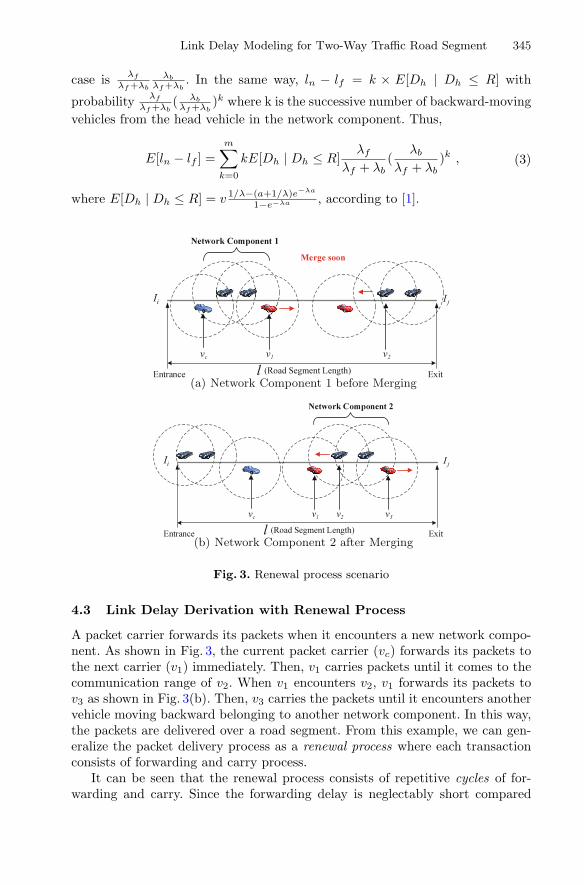
Fig. 3. Renewal process scenario
4.3 Link Delay Derivation with Renewal Process
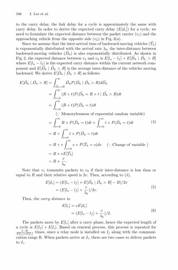
A packet carrier forwards its packets when it encounters a new network compo-nent. As shown in Fig. 3, the current packet carrier (vc) forwards its packets tothe next carrier (v1) immediately. Then, v1 carries packets until it comes to thecommunication range of v2. When v1 encounters v2, v1 forwards its packets tov3 as shown in Fig. 3(b). Then, v3 carries the packets until it encounters anothervehicle moving backward belonging to another network component. In this way,the packets are delivered over a road segment. From this example, we can gen-eralize the packet delivery process as a renewal process where each transactionconsists of forwarding and carry process.
It can be seen that the renewal process consists of repetitive cycles of for-warding and carry. Since the forwarding delay is neglectably short compared
346 J. Lee et al.
to the carry delay, the link delay for a cycle is approximately the same withcarry delay. In order to derive the expected carry delay (E[dc]) for a cycle, weneed to formulate the expected distance between the packet carrier (v1) and theapproaching vehicle from the opposite side (v2) in Fig. 3(a).
Since we assume that the inter-arrival time of backward-moving vehicles (T̃h)is exponentially distributed with the arrival rate λb, the inter-distance betweenbackward-moving vehicles (D̃h) is also exponentially distributed. As shown inFig. 2, the expected distance between v1 and v2 is E[ln − lf ] + E[D̃h | D̃h > R]where E[ln − lf ] is the expected carry distance within the current network com-ponent and E[D̃h | D̃h > R] is the average inter-distance of the vehicles movingbackward. We derive E[D̃h | D̃h > R] as follows:
E[D̃h | D̃h > R] =∫ ∞
D̃h=R
D̃hP (D̃h | D̃h > R)dD̃h
=∫ ∞
t=0
(R + t)P (D̃h = R + t | D̃h > R)dt
=∫ ∞
t=0
(R + t)P (D̃h = t)dt
(∵ Memorylessness of expoential random variable)
=∫ ∞
t=0
R × P (D̃h = t)dt +∫ ∞
t=0
t × P (D̃h = t)dt
= R +∫ ∞
t=0
t × P (D̃h = t)dt
= R + v
∫ ∞
s=0
s × P (T̃h = s)ds (∵ Change of variable )
= R + vE[T̃h]
= R +v
λb.
(4)
Note that v1 transmits packets to v2 if their inter-distance is less than orequal to R and their relative speed is 2v. Then, according to (4),
E[dc] = (E[ln − lf ] + E[D̃h | D̃h > R] − R)/2v
= (E[ln − lf ] +v
λb)/2v.
(5)
Then, the carry distance is:
E[lc] = vE[dc]
= (E[ln − lf ] +v
λb)/2.
(6)
The packets move by E[lc] after a carry phase, hence the expected length ofa cycle is E[lf ] + E[lc]. Based on renewal process, this process is repeated for
l−RE[lf ]+E[lc]
times, since a relay node is installed on Ij along with the communi-cation range R. When packets arrive at Ii, there are two cases to deliver packetsto Ii.

Link Delay Modeling for Two-Way Traffic Road Segment 347
– Case 1: Immediate Forward: Assume that T ∗ is the inter-arrival timebetween the vehicles moving forward. If there is a next packet carrier in thecommunication range of the relay node at Ii, such a probability and the con-ditional expectation of link delay are:
P (Case 1) = P (T ∗h < a)
= 1 − e−λf a,
E[Link Delay|Case 1] =l − R
E[lf ] + E[lc]× E[dc].
(7)
– Case 2: Wait and Carry: If there is no vehicle moving forward in the com-munication range of the relay node at Ii, such a probability and the conditionalexpectation of link delay are:
P (Case 2) = P (T ∗h ≥ a)
= e−λf a,
E[Link Delay|Case 2] =1λf
+l − R
E[lf ] + E[lc]× E[dc].
(8)
Considering both cases, the average link delay with relay nodes on eachintersection is:
E[Link Delay] = P (Case 1)E[Link Delay|Case 1] + P (Case 2)E[Link Delay|Case 2]
=1
λfe−λf a +
l − R
E[lf ] + E[lc]× E[dc].
(9)
5 Performance Evaluation
We validate of our model by comparing its expectation with simulation result. Asshown in Table 1, vehicles travel over path length 1000m from both ends of thestraight road. They move with speed v ∼ N(40, 5) MPH. The communicationrange of DRRC deivces is 200m. At both ends (i.e., intersections), relay nodesare installed.
– Performance Metric: We compare average link delay with the expected linkdelay.
– Parameters: We investgate the impacts of average arrival rate λ(= λf +λb),average vehicle speed μv, and vehicle speed deviation σv.
Our model is compared with simulation result which approximates the groundtruth. Furthermore, we also compare the simulation result of two-way traffic withthat of one-way traffic.

348 J. Lee et al.
5.1 Impact of Vehicle Arrival Rate λ
At first, we show how the link delay changes as the vehicle inter-arrival timevaries. Note that the vehicle inter-arrival time is the reciprocal of vehicle arrivalrate λ. As shown in Fig. 4, one-way simulation result has longer delay than two-way simulation result. Vehicles deliver packets faster by using two-way traffic.
Table 1. Simulation Configuration
Parameter Description
Road condition The road is straight and 1km long.
Communication range R = 200 meters (i.e., 656 feet).
Arrival rates λf = λb = 1/10 where λf is the arrival rate for forward
vehicular traffic and λb is the arrival rate for backward
vehicular traffic.
Vehicle speed v ∼ N(40, 5) MPH.
0
5
10
15
20
25
30
35
40
45
50
55
60
2 4 6 8 10 12 14 16 18 20
Lin
k D
elay
(se
c.)
Vehicle Inter-arrival Time (sec.)
One-way Sim.
Two-way Sim.
Two-way Model
[9]
Fig. 4. Link delay versus vehicle inter-arrival time
0
5
10
15
20
25
30
35
40
45
50
20 25 30 35 40 45 50 55 60
Lin
k D
elay
(se
c.)
Vehicle Speed (MPH)
One-way Sim.
Two-way Sim.
Two-way Model
[9]
Fig. 5. Link delay versus average vehicle speed

Link Delay Modeling for Two-Way Traffic Road Segment 349
Thus, we can deliver packets with shorter delay if we utilize the direction andlocation information from the GPS based navigation system. As shown in Fig. 4,our model accurately expects the link delay. Since [9] does not consider themobility of vehicles toward forwarding direction, the expectation diverges expo-nentially. In comparison with [9], our model provides relatively closer result tothe simulation result.
5.2 The Impact of Vehicle Speed μv
Here, we investigate the impact of vehicle speed to the link delay. As shown inFig. 5, in our two-way model and two-way simulation, the higher vehicular speedresults in the longer delivery delay for the dense traffic case. This is because thehigher speed causes the longer inter-distance between vehicles. Moreover, theprobability to construct a network component becomes low. Thus, the higherspeed results in the longer delay for even heavy traffic case.
0
5
10
15
20
25
30
35
40
45
1 2 3 4 5 6 7 8 9 10
Lin
k D
elay
(se
c.)
Vehicle Speed Standard Deviation (MPH)
One-way Sim.
Two-way Sim.
Fig. 6. Link delay versus vehicle speed standard deviation
5.3 The Impact of Vehicle Speed Deviation σv
We observe the impact of vehicle speed deviation to the link delay. We increasevehicle speed standard deviation from 1 to 10 MPH. As shown in Fig. 6, linkdelay becomes shorter as the speed standard deviation becomes larger. If twovehicles move to the same direction with the same speed, and they are out ofcommunication range, there is no chance to make a network component. How-ever, in case of different speed case, a faster vehicle can catch up with a slowervehicle and they can construct a network component. This phenomenon happensmore often in case of a large standard deviation than a low standard deviation.

350 J. Lee et al.
6 Conclusion
In this paper, we propose average link delay for a road segment with two-wayroad traffic. In order to derive the expectation, we introduce the concept ofrenewal process. This assumes that the forwarding and carry phases alternaterepeatedly. We formulate link delay for a cycle because the carry delay is domi-nant, assuming that the inter-arrival time is distributed exponentially. This linkdelay modeling can be used for multihop infrastructure-to-vehicle data deliveryin road networks. Two-way roads are dominant over one-way roads in real roadnetworks. As future work, we will investigate link delay model, considering morerealistic environments such as road networks with traffic signals. Also, we willevaluate data forwarding schemes for the multihop infrastructure-to-vehicle datadelivery with our link delay model.
Acknowledgment. This research was supported by Basic Science Research Programthrough the National Research Foundation of Korea (NRF) funded by the Ministry ofScience, ICT & Future Planning (2014006438). This research was supported in part byGlobal Research Laboratory Program (2013K1A1A2A02078326) through NRF, and theICT R&D program of MSIP/IITP (14-824-09-013, Resilient Cyber-Physical SystemsResearch) and the DGIST Research and Development Program (CPS Global Center)funded by the Ministry of Science, ICT & Future Planning. Note that Jaehoon (Paul)Jeong is the corresponding author.
References
1. Jeong, J., Guo, S., Gu, Y., He, T., Du, D.H.C.: Trajectory-based data forwardingfor light-traffic vehicular ad hoc networks. IEEE Trans. Parallel Distrib. Syst. 22(5),743–757 (2011)
2. Jeong, J., Guo, S., Gu, Y., He, T., Du, D.H.C.: Trajectory-based statistical forward-ing for multihop infrastructure-to-vehicle data delivery. IEEE Trans. Mob. Comput.11(10), 1523–1597 (2012)
3. Carter, A.: The Status of Vehicle-to-Vehicle Communication as a Means of Improv-ing Crash Prevention Performance. Technical report 05–0264 (2005). http://www-nrd.nhtsa.dot.gov/pdf/nrd-01/esv/esv19/05-0264-W.pdf
4. U.S. Department of Transportation. Federal Motor Vehicle Safety Stan-dards: Vehicle-to-Vehicle (V2V) Communications. http://www.gpo.gov/fdsys/pkg/FR-2014-08-20/pdf/2014-19746.pdf
5. Rauwald, C., Nichols, H.: Audi Tests Driverless-Car Technology at 190MPH, Octo-ber 2014
6. Ramsey, M., Fowler, G.: Ford chief says Mass-Market autonomous vehicle is priority,January 2015
7. LeBeau, P.: Mercedes’ futuristic view: Autonomy meets connectivity, January 20158. Jeong, J., He, T., Du, D.H.C.: TMA: Trajectory-based Multi-Anycast for Multicast
Data Delivery in Vehicular Networks. Technical Report 11–013. http://www.cs.umn.edu/tech reports upload/tr2011/11-013.pdf
9. Liu, Y., Niu, J., Ma, J., Shu, L., Hara, T., Wang, W.: The insights of messagedelivery delay in VANETs with a bidirectional traffic model. J. Netw. Comput.Appl. 36, 1287–1294 (2013)