lichtschranken baureihe wl 27-2w 4-2 photoelectric
TRANSCRIPT

46 SENSICK CATALOGUE 2000
A
46 SENSICK CATALOGUE
Lichtschranken Baureihe WL 27-2Lichtschranken Baureihe WL 27-2W 4-2 Photoelectric switches
W 4-2 series:
Small but powerful
As small as a sugar cube and as
powerful as a ”large” photoelectric
switch – these are the two
principal features of the W 4-2
photoelectric switch series.
They are used in particularly
narrow locations and where only
limited mounting space is avail-
able. Insensitivity to ambient light
(e.g. from HF or flashing warning
lamps) and a high level of func-
tional reliability if devices are
installed opposite each other are
particularly important for trouble-
free operation. Sensor housings
are made of fully welded plastic
(ABS). Temperature variations
between – 40 and + 60 °C,
splash-water and dust do not
reduce the reliability of object
detection. Suitable areas of appli-
cation are the food-processing,
beverage and tobacco industries,
the electronics sector and pack-
aging machines.
The WT 4-2 photoelectric proxi-
mity switch can be adjusted to
scanning ranges between 4 and
130 mm. Whatever the individual
application, the sensor allows the
appropriate background suppres-
sion to be selected.
WL 4-2 is the name of the photo-
electric reflex switch in this series.
It can detect objects reliably at a
distance of up to 2.8 metres.
The WL 4G-2 glass photoelectric
switch has been specially
developed for use in the packag-
ing and beverage industries. It is
easier to install, simpler to cali-
brate and has a greater scanning
range than fibre-optic sensors. If
a polarising filter is used, it also
allows reflective objects to be
detected, e.g. partially printed or
aluminised foils.
The WS/WE 4-2 through-beam
photoelectric switch has a scan-
ning range of 4 metres. Like the
other sensors in this series it
uses visible light which makes
adjustment and alignment of the
sensor during commissioning
much easier.
Photoelectric proximity switchesBGS
Through-beam photoelectricswitches
Photoelectric reflex switches
47SENSICK CATALOGUE
WL 27-2 W 4-2
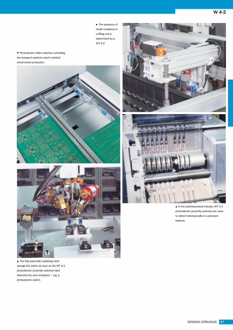
n The presence of
small containers in
a lifting unit is
determined by a
WT 4-2.
b Photoelectric reflex switches controlling
the transport systems used in printed
circuit board production.
v In the pharmaceutical industry: WT 4-2
photoelectric proximity switches are used
to detect individual pills in a precision
balance.
v The fully automatic soldering robot
springs into action as soon as the WT 4-2
photoelectric proximity switches have
detected the next workpiece – e.g. a
photoelectric switch.

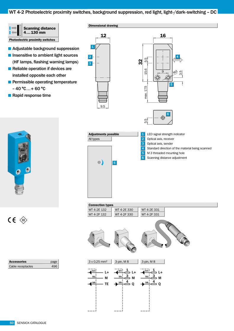
WT 4-2 Photoelectric proximity switches, background suppression, red light, light-/dark-switching -- DC
48 SENSICK CATALOGUE
brn
blu
blk
L+
M
Q
1L+
M
Q
3
4
brn
blu
blk
1L+
M
Q
3
4
Q2
brn
blu
blk
wht
1L+
M
Q
3
4
brn
blu
blk
16
5.5
15
.6
32
3.5
max. 1
7.5
9
12
9.5
M3
1
2
3
5
6
5.5
4
Photoelectric proximity switches
Scanning distance4 . . . 130 mm
■ Adjustable background suppression
■ Insensitive to ambient light sources
(HF lamps, flashing warning lamps)
■ Reliable operation if devices are
installed opposite each other
■ Permissible operating temperature
-- 40 °C . . .+ 60 °C
■ Rapid response time
Dimensional drawing
Connection types
All types
Adjustments possible LED signal strength indicator
Optical axis, receiver
Optical axis, sender
Standard direction of the material being scanned
M 3 threaded mounting hole
Scanning distance adjustment6
6
5
4
3
2
1
WT 4-2P 132
WT 4-2N 132
3 x 0.25 mm2 3-pin, M 8 4-pin, M 8 3-pin, M 8
WT 4-2P 330 WT 4-2P 430
WT 4-2N 330
WT 4-2P 331
WT 4-2N 331
Accessories page
Cable receptacles 496
C �

WT 4-2
49SENSICK CATALOGUE
1
3
2
(mm) 30 50 70 90 110 130
15
10
5
0% o
f th
e s
cannin
g d
ista
nce
6%/90%
18%/90%
90%/90%
1) Average service life 100,000 h
where TA = + 25 °C
2) Limit values
3) May not exceed or fall short of
VS tolerances
4) Without load
5) Signal transit time with resistive load
6) With light/dark ratio 1:1
7) Do not bend below 0 °C
8) A = VS connections reverse-polarity
protected
B = Output Q and QQ–
short-circuit
protected
C = Interference pulse suppression
9) IP 67: with screw-in cable receptacles
IP 65: with plug-in cable receptacles
Technical data WT 4-2 P 132 P 330 P 331 N 132 N 330 N 331 P 430
Scanning distance
Type Part no.
WT 4-2P 132 1 015 150
WT 4-2P 330 1 015 143
WT 4-2P 331 1 015 145
WT 4-2N 132 1 012 874
WT 4-2N 330 1 012 920
WT 4-2N 331 1 015 147
WT 4-2P 430 1 015 957
Order information
3 Scanning distance on white, 90 % remission
2 Scanning distance on grey, 18 % remission
Scanning distance on black, 6 % remission1
Scanning distance 4. . .130 mm, adjustable
Background suppression adjustable from 20 mm
Light source1), light type LED, red light
Light spot diameter 3 mm at 50 mm
Supply voltage VS 10. . .30 V DC2)
Ripple3) 5 VSS
Current consumption4) < 20 mA
Switching outputs PNP, Q
NPN, Q
PNP, Q and Q–
Switching mode Light-switching
Dark-switching
Output current IA max. 100 mA
PNP; signal voltage HIGH VS – (< 2.5 V)
PNP; signal voltage LOW Approx. 0 V
NPN; signal voltage HIGH Approx. VS
NPN; signal voltage LOW < 1.5 V
Response time5) < 500 µs
Max. switching frequency6) 1000/s
Connection types Cable7), 2 m
Plug M 8
Cable7), 100 mm, with plug
VDE protection class �Circuit protection8) A, B, C
Enclosure rating9) IP 67
Ambient temperature TA Operation – 40 °C . . .+ 60 °C
Storage – 40 °C . . .+ 75 °C
Weight Approx. 20 g
Housing material PC, polycarbonate
0 (mm) 30 50 70 90 110 130
4 100
4 130
4 100
1
2
3
50 SENSICK CATALOGUE
WT 4-2 Photoelectric proximity switches, background suppression, red light, light-/dark-switching -- DC
brn
blu
blk
L+
M
TE
1L+
M
Q
3
4
brn
blu
blk
1L+
M
Q
3
4
brn
blu
blk
16
5.5
15
.6
32
3.5
max. 1
7.5
9
12
9.5
M3
1
2
3
5
6
5.5
4
Photoelectric proximity switches
Scanning distance4 . . . 130 mm
■ Adjustable background suppression
■ Insensitive to ambient light sources
(HF lamps, flashing warning lamps)
■ Reliable operation if devices are
installed opposite each other
■ Permissible operating temperature
-- 40 °C . . .+ 60 °C
■ Rapid response time
Dimensional drawing
All types
Adjustments possible LED signal strength indicator
Optical axis, receiver
Optical axis, sender
Standard direction of the material being scanned
M 3 threaded mounting hole
Scanning distance adjustment6
6
5
4
3
2
1
Connection types
WT 4-2E 132
WT 4-2F 132
3 x 0.25 mm2 3-pin, M 8 3-pin, M 8
WT 4-2E 330
WT 4-2F 330
WT 4-2E 331
WT 4-2F 331
Accessories page
Cable receptacles 496
C �

51SENSICK CATALOGUE
WL 27-2 WT 4-2
1
3
2
(mm) 30 50 70 90 110 130
15
10
5
0% o
f th
e s
cannin
g d
ista
nce
6%/90%
18%/90%
90%/90%
Technical data WT 4-2 E 132 E 330 E 331 F 132 F 330 F 331
Scanning distance
Type Part no.
WT 4-2E 132 1 012 875
WT 4-2E 330 1 013 787
WT 4-2E 331 1 015 148
WT 4-2F 132 1 012 873
WT 4-2F 330 1 015 144
WT 4-2F 331 1 015 146
Order information
Scanning distance 4. . .130 mm, adjustable
Background suppression adjustable from 20 mm
Light source1), light type LED, red light
Light spot diameter 3 mm at 50 mm
Supply voltage VS 10. . .30 V DC2)
Ripple3) 5 VSS
Current consumption4) < 20 mA
Switching outputs PNP, Q
NPN, Q
Switching mode Dark-switching
Output current IA max. 100 mA
PNP; signal voltage HIGH VS – (< 2.5 V)
PNP; signal voltage LOW Approx. 0 V
NPN; signal voltage HIGH Approx. VS
NPN; signal voltage LOW < 1.5 V
Response time5) < 500 µs
Max. switching frequency6) 1000/s
Connection types Cable7), 2 m
Plug M 8
Cable7), 100 mm, with plug
VDE protection class �Circuit protection8) A, B, C
Enclosure rating9) IP 67
Ambient temperature TA Operation – 40 °C . . .+ 60 °C
Storage – 40 °C . . .+ 75 °C
Weight Approx. 20 g
Housing material PC, polycarbonate
1) Average service life 100,000 h
where TA = + 25 °C
2) Limit values
3) May not exceed or fall short of
VS tolerances
4) Without load
5) Signal transit time with resistive load
6) With light/dark ratio 1:1
7) Do not bend below 0 °C
8) A = VS connections reverse-polarity
protected
B = Output Q short-circuit protected
C = Interference pulse suppression
9) IP 67: with screw-in cable receptacles
IP 65: with plug-in cable receptacles
3 Scanning distance on white, 90 % remission
2 Scanning distance on grey, 18 % remission
Scanning distance on black, 6 % remission1
0 (mm) 30 50 70 90 110 130
4 100
4 130
4 100
1
2
3

52 SENSICK CATALOGUE
WL 4-2 Photoelectric reflex switches, red light, dark-switching -- DC
brn
blu
blk
L+
M
Q
1L+
M
Q
3
4
brn
blu
blk
1L+
M
Q
3
4
Q2
brn
blu
blk
wht
1L+
M
Q
3
4
brn
blu
blk
16
5.5
15
.6
32
3.5
max. 1
7.5
9
12
9.5
M3
1
2
3
4
Photoelectric reflex switches
Scanning range2.8 m
■ Insensitive to ambient light sources
(HF lamps, flashing warning lamps)
■ Reliable operation if devices are
installed opposite each other
■ Permissible operating temperature
-- 40 °C . . .+ 60 °C
■ Rapid response time
Dimensional drawing
LED signal strength indicator
Optical axis, receiver
Optical axis, sender
M 3 threaded mounting hole4
3
2
1
C �
Connection types
WL 4-2P 132
WL 4-2N 132
WL 4-2P 330
WL 4-2N 330
WL 4-2P 331
WL 4-2N 331
WL 4-2P 430
3 x 0.25 mm2 3-pin, M 8 4-pin, M 8 3-pin, M 8Accessories page
Cable receptacles 496
Reflectors 520

0.7
0.7
1
1.7
1.7
2.8
53SENSICK CATALOGUE
WL 27-2 WL 4-2
1
6
(m) 1 2 3
100
10
1Opera
ting r
eserv
e
3
Operating range
Scanning range,max. typical
Technical data WL 4-2 P 132 P 330 P 331 N 132 N 330 N 331 P 430
Operating range and operating reserve
Type Part no.
WL 4-2P 132 1 015 767
WL 4-2P 330 1 015 763
WL 4-2P 331 1 015 759
WL 4-2N 132 1 015 769
WL 4-2N 330 1 015 765
WL 4-2N 331 1 015 761
WL 4-2P 430 1 015 958
Order information
0 1.7
0 0.8
0 1.1
1
2
3
0 0.4
0 0.45
0 0.46
0 (m) 0.5 1 1.5 2 2.5 3
PL 80 A
PL 50 A
PL 40 A
PL 30 A
PL 20 A
Reflective tape
Diamond Grade
0 . . .1.7 m
Reflector type Operating range
0. . .1.1 m
0 . . .0.8 m
0 . . .0.4 m
0 . . .0.4 m
35. . .400 mm6
5
4
3
2
1
4
1) Average service life 100,000 h
where TA = + 25 °C
2) Limit values
3) May not exceed or fall short of
VS tolerances
4) Without load
5) Signal transit time with resistive load
6) With light/dark ratio 1:1
7) Do not bend below 0 °C
8) A = VS connections reverse-polarity
protected
B = Output Q and QQ–
short-circuit
protected
C = Interference pulse suppression
9) IP 67: with screw-in cable receptacles
IP 65: with plug-in cable receptacles
Scanning range, max. typical/ 2.8 m/PL 80 A
on reflector
Light source1), light type LED, red light
Light spot diameter 230 mm at 1.5 m
At focal point Approx. 3.5 mm at 90 mm
Supply voltage VS 10. . .30 V DC2)
Ripple3) 5 VSS
Current consumption4) < 20 mA
Switching outputs PNP, Q
NPN, Q
PNP, Q and Q–
Switching mode Dark-switching
Light-switching
Output current IA max. 100 mA
PNP; signal voltage HIGH VS – (< 2.5 V)
PNP; signal voltage LOW Approx. 0 V
NPN; signal voltage HIGH Approx. VS
NPN; signal voltage LOW < 1.5 V
Response time5) < 500 µs
Max. switching frequency6) 1000/s
Connection types Cable7), 2 m
Plug M 8
Cable7), 100 mm, with plug
VDE protection class �Circuit protection8) A, B, C
Enclosure rating9) IP 67
Ambient temperature TA Operation – 40 °C . . .+ 60 °C
Storage – 40 °C . . .+ 75 °C
Weight Approx. 20 g
Polarising filter
Housing material PC, polycarbonate

54 SENSICK CATALOGUE
WL 4-2 Photoelectric reflex switches, red light, dark-switching -- DC
brn
blu
blk
L+
M
Q
1L+
M
Q
3
4
brn
blu
blk
1L+
M
Q
3
4
brn
blu
blk
16
5.5
15
.6
32
3.5
max. 1
7.5
9
12
9.5
M3
1
2
3
4
Photoelectric reflex switches
Scanning range2.8 m
■ Insensitive to ambient light sources
(HF lamps, flashing warning lamps)
■ Reliable operation if devices are
installed opposite each other
■ Permissible operating temperature
-- 40 °C . . .+ 60 °C
■ Rapid response time
Dimensional drawing
C �
WL 4-2E 132
WL 4-2F 132
WL 4-2E 330
WL 4-2F 330 WL 4-2F 331
WL 4-2E 331
3 x 0.25 mm2 3-pin, M 8 3-pin, M 8Accessories page
Cable receptacles 496
Reflectors 520
LED signal strength indicator
Optical axis, receiver
Optical axis, sender
M 3 threaded mounting hole4
3
2
1
Connection types

55SENSICK CATALOGUE
WL 27-2 WL 4-2
1
6
(m) 1 2 3
100
10
1Opera
ting r
eserv
e
3
Operating range
Scanning range,max. typical
Technical data WL 4-2 E 132 E 330 E 331 F 132 F 330 F 331
Operating range and operating reserve
Type Part no.
WL 4-2E 132 1 015 770
WL 4-2E 330 1 015 766
WL 4-2E 331 1 015 762
WL 4-2F 132 1 015 768
WL 4-2F 330 1 015 764
WL 4-2F 331 1 015 760
Order information
0 (m) 0.5 1 1.5 2 2.5 3
0.7
0.7
0.8
1.5
1.8
2.80 1.7
0 0.8
0 1.1
1
2
3
0 0.44
0 0.45
0 0.46
Scanning range, max. typical/ 2.8 m/PL 80 A
on reflector
Light source1), light type LED, red light
Light spot diameter 230 mm at 1.5 m
At focal point Approx. 3.5 mm at 90 mm
Supply voltage VS 10. . .30 V DC2)
Ripple3) 5 VSS
Current consumption4) < 20 mA
Switching outputs PNP, Q
NPN, Q
Switching mode Dark-switching
Output current IA max. 100 mA
PNP; signal voltage HIGH VS – (< 2.5 V)
PNP; signal voltage LOW Approx. 0 V
NPN; signal voltage HIGH Approx. VS
NPN; signal voltage LOW < 1.5 V
Response time5) < 500 µs
Max. switching frequency6) 1000/s
Connection types Cable7), 2 m
Plug M 8
Cable7), 100 mm, with plug
VDE protection class �Circuit protection8) A, B, C
Enclosure rating9) IP 67
Ambient temperature TA Operation – 40 °C . . .+ 60 °C
Storage – 40 °C . . .+ 75 °C
Weight Approx. 20 g
Polarising filter
Housing material PC, polycarbonate
1) Average service life 100,000 h
where TA = + 25 °C
2) Limit values
3) May not exceed or fall short of
VS tolerances
4) Without load
5) Signal transit time with resistive load
6) With light/dark ratio 1:1
7) Do not bend below 0 °C
8) A = VS connections reverse-polarity
protected
B = Output Q short-circuit protected
C = Interference pulse suppression
9) IP 67: with screw-in cable receptacles
IP 65: with plug-in cable receptacles
PL 80 A
PL 50 A
PL 40 A
PL 30 A
PL 20 A
Reflective tape
Diamond Grade
0 . . .1.7 m
Reflector type Operating range
0. . .1.1 m
0 . . .0.8 m
0 . . .0.4 m
0 . . .0.4 m
35. . .400 mm6
5
4
3
2
1

56 SENSICK CATALOGUE
WL 4G-2 Photoelectric reflex switches, for transparent objects, red light -- DC
1L+
M
Q
3
4
brn
blu
blk
5
4.9
1
2
3
12
9.5
4
3.59 M3
5.5
15
.6
32
max. 1
7.5
16 3
Photoelectric reflex switches
Scanning range1.6 m
■ Detects glass and transparent films
■ Insensitive to ambient light sources
(HF lamps, flashing warning lamps)
■ Reliable operation if devices are
installed opposite each other
■ Permissible operating temperature
-- 40 °C . . .+ 60 °C
■ Rapid response time
Dimensional drawing
C �WL 4G-2F 330
3-pin, M 8Accessories page
Cable receptacles 496
Reflectors 520
LED signal strength indicator
Optical axis, receiver
Optical axis, sender
M 3 threaded mounting hole
Sensitivity control5
5
Connection type
WL 4G-2F 330
Adjustments possible
4
3
2
1

57SENSICK CATALOGUE
WL 4G-2
(m) 0.2 0.4 0.6 0.8 1
20
10
12
14
16
18
0
2
4
6
8
Transm
issio
n a
ttenuation in %
(sin
gle
lig
ht
beam
)
Technical data WL 4G-2 F 330
Operating range and transmission attenuation
Type Part no.
WL 4G-2F 330 1 016 209
Order information
0 (m) 0.2 0.4 0.6 0.8 1.0
■ Operating range
0.05 1.0
0.05 0.5
0.05 0.6
1
2
3
0.05 0.354
PL 80 A
PL 50 A
PL 40 A
PL 30 A
0.05 . . .1.0 m
Operating range
0.05 . . .0.6 m
0.05 . . .0.5 m
0.05 . . .0.35 m4
3
2
1
1) Average service life 100,000 h
where TA = + 25 °C
2) Limit values
3) May not exceed or fall short of
VS tolerances
4) Without load
5) Signal transit time with resistive load
6) With light/dark ratio 1:1
7) A = VS connections reverse-polarity
protected
B = Output Q short-circuit protected
C = Interference pulse suppression
8) IP 67: with screw-in cable receptacles
IP 65: with plug-in cable receptacles
Reflector type
Scanning range, max. typical/ 1.6 m/PL 80 A
on reflector
Sensitivity Adjustable
Light source1), light type LED, red light
Light spot diameter 230 mm at 1.5 m
Supply voltage VS 10. . .30 V DC2)
Ripple3) 5 VSS
Current consumption4) < 20 mA
Switching outputs PNP, Q
Switching mode Dark-switching
Output current IA max. 100 mA
PNP; signal voltage HIGH VS – (< 2.5 V)
PNP; signal voltage LOW Approx. 0 V
Response time5) < 500 µs
Max. switching frequency6) 1000/s
Connection type Plug M 8
VDE protection class �Circuit protection7) A, B, C
Enclosure rating8) IP 67
Ambient temperature TA Operation – 40 °C . . .+ 60 °C
Storage – 40 °C . . .+ 75 °C
Weight Approx. 20 g
Polarising filter
Housing material PC, polycarbonate

C �
58 SENSICK CATALOGUE
WS/WE 4-2 Through-beam photoelectric switches, light-switching -- DC
16
5.5
15
.6
32
3.5
max. 1
7.5
9
12
9.5
M3
1
2
3
4
brn
blu
blk
L+
M
Q
1L+
M
Q
3
4
brn
blu
blk
1L+
M
Q
3
4
brn
blu
blk
brn
blu
blk
L+
M
TE
1L+
M
TE
3
4
brn
blu
blk
1L+
M
TE
3
4
brn
blu
blk
Through-beam photoelectric switches
Scanning range4 m
■ Insensitive to ambient light sources
(HF lamps, flashing warning lamps)
■ Permissible operating temperature
-- 40 °C . . .+ 60 °C
■ Rapid response time
■ Test input for system diagnosis
Dimensional drawing
WS/WE 4-2P 132
WS/WE 4-2N 132
3 x 0.25 mm2
Sender
Receiver
3-pin, M 8 3-pin, M 8
WS/WE 4-2P 330
WS/WE 4-2N 330
WS/WE 4-2P 331
WS/WE 4-2N 331
Accessories page
Cable receptacles 496
LED signal strength indicator
Optical axis, receiver
Optical axis, sender
M 3 threaded mounting hole
Connection types
4
3
2
1
59SENSICK CATALOGUE
(m) 1 2 3 4
100
10
1Opera
ting r
eserv
e
Operating range
Scanning range, max. typical
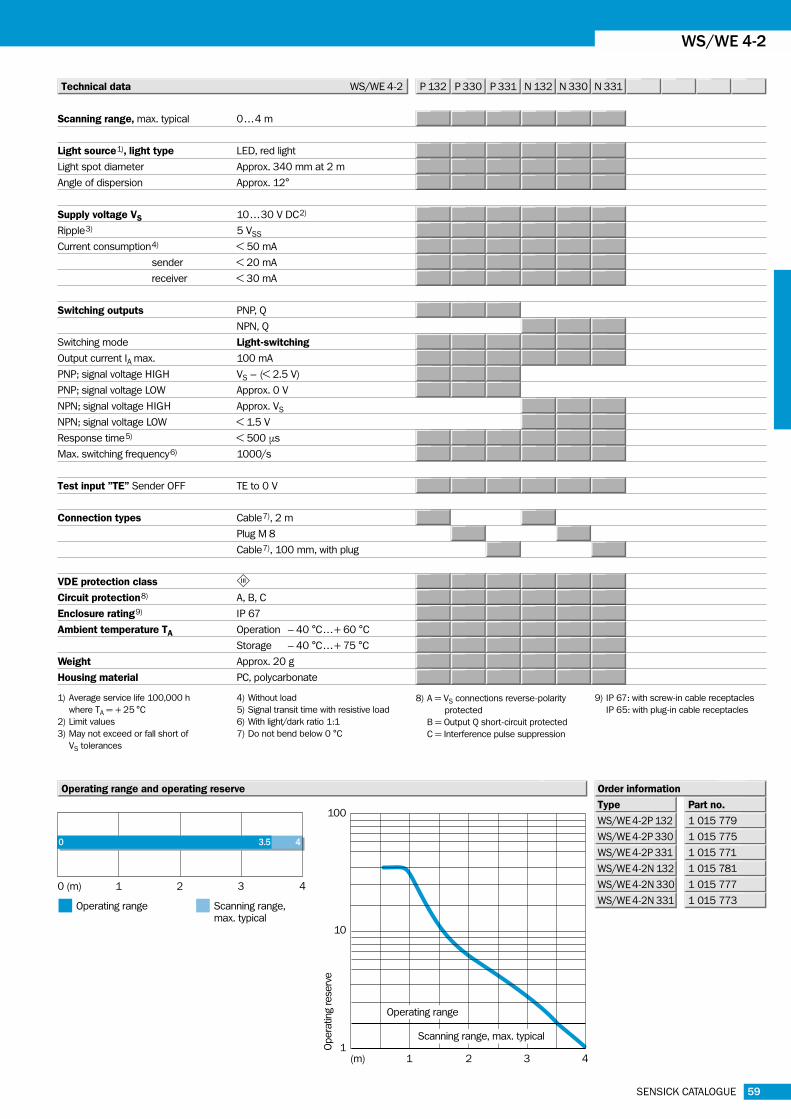
Technical data WS/WE 4-2 P 132 P 330 P 331 N 132 N 330 N 331
Operating range and operating reserve
40 3.5
0 (m) 1 2 3 4
■ Operating range ■ Scanning range,
max. typical
Type Part no.
1 015 779
1 015 775
1 015 771
1 015 781
1 015 777
1 015 773
Order information
WS/WE 4-2P 132
WS/WE 4-2P 330
WS/WE 4-2P 331
WS/WE 4-2N 132
WS/WE 4-2N 330
WS/WE 4-2N 331
WS/WE 4-2
Scanning range, max. typical 0 . . .4 m
Light source1), light type LED, red light
Light spot diameter Approx. 340 mm at 2 m
Angle of dispersion Approx. 12°
Supply voltage VS 10. . .30 V DC2)
Ripple3) 5 VSS
Current consumption4) < 50 mA
sender < 20 mA
receiver < 30 mA
Switching outputs PNP, Q
NPN, Q
Switching mode Light-switching
Output current IA max. 100 mA
PNP; signal voltage HIGH VS – (< 2.5 V)
PNP; signal voltage LOW Approx. 0 V
NPN; signal voltage HIGH Approx. VS
NPN; signal voltage LOW < 1.5 V
Response time5) < 500 µs
Max. switching frequency6) 1000/s
Test input ”TE” Sender OFF TE to 0 V
Connection types Cable7), 2 m
Plug M 8
Cable7), 100 mm, with plug
VDE protection class �Circuit protection8) A, B, C
Enclosure rating9) IP 67
Ambient temperature TA Operation – 40 °C . . .+ 60 °C
Storage – 40 °C . . .+ 75 °C
Weight Approx. 20 g
Housing material PC, polycarbonate
1) Average service life 100,000 h
where TA = + 25 °C
2) Limit values
3) May not exceed or fall short of
VS tolerances
4) Without load
5) Signal transit time with resistive load
6) With light/dark ratio 1:1
7) Do not bend below 0 °C
8) A = VS connections reverse-polarity
protected
B = Output Q short-circuit protected
C = Interference pulse suppression
9) IP 67: with screw-in cable receptacles
IP 65: with plug-in cable receptacles

60 SENSICK CATALOGUE
WS/WE 4-2 Through-beam photoelectric switches, dark-switching -- DC
16
5.5
15
.6
32
3.5
max. 1
7.5
9
12
9.5
M3
1
2
3
4
brn
blu
blk
L+
M
Q
1L+
M
Q
3
4
brn
blu
blk
1L+
M
Q
3
4
brn
blu
blk
brn
blu
blk
L+
M
TE
1L+
M
TE
3
4
brn
blu
blk
1L+
M
TE
3
4
brn
blu
blk
C �
Through-beam photoelectric switches
Scanning range4 m
■ Insensitive to ambient light sources
(HF lamps, flashing warning lamps)
■ Permissible operating temperature
-- 40 °C . . .+ 60 °C
■ Rapid response time
■ Test input for system diagnosis
Dimensional drawing
WS/WE 4-2E 132
WS/WE 4-2F 132
3 x 0.25 mm2
Sender
Receiver
3-pin, M 8 3-pin, M 8
WS/WE 4-2E 330
WS/WE 4-2F 330
WS/WE 4-2E 331
WS/WE 4-2F 331
Accessories page
Cable receptacles 496
LED signal strength indicator
Optical axis, receiver
Optical axis, sender
M 3 threaded mounting hole
Connection types
4
3
2
1

61SENSICK CATALOGUE
(m) 1 2 3 4
100
10
1Opera
ting r
eserv
e
Operating range
Scanning range, max. typical
Technical data WS/WE 4-2 E 132 E 330 E 331 F 132 F 330 F 331
Operating range and operating reserve
Type Part no.
1 015 782
1 015 778
1 015 774
1 015 780
1 015 776
1 015 772
Order information
WS/WE 4-2E 132
WS/WE 4-2F 132
WS/WE 4-2E 330
WS/WE 4-2F 330
WS/WE 4-2E 331
WS/WE 4-2F 331
WS/WE 4-2
40 3.5
0 (m) 1 2 3 4
■ Operating range ■ Scanning range,
max. typical
1) Average service life 100,000 h
where TA = + 25 °C
2) Limit values
3) May not exceed or fall short of
VS tolerances
4) Without load
5) Signal transit time with resistive load
6) With light/dark ratio 1:1
7) Do not bend below 0 °C
8) A = VS connections reverse-polarity
protected
B = Output Q short-circuit protected
C = Interference pulse suppression
9) IP 67: with screw-in cable receptacles
IP 65: with plug-in cable receptacles
Scanning range, max. typical 0 . . .4 m
Light source1), light type LED, red light
Light spot diameter Approx. 340 mm at 2 m
Angle of dispersion Approx. 12°
Supply voltage VS 10. . .30 V DC2)
Ripple3) 5 VSS
Current consumption4) < 50 mA
sender < 50 mA
receiver < 30 mA
Switching outputs PNP, Q
NPN, Q
Switching mode Dark-switching
Output current IA max. 100 mA
PNP; signal voltage HIGH VS – (< 2.5 V)
PNP; signal voltage LOW Approx. 0 V
NPN; signal voltage HIGH Approx. VS
NPN; signal voltage LOW < 1.5 V
Response time5) < 500 µs
Max. switching frequency6) 1000/s
Test input ”TE” Sender OFF TE to 0 V
Connection types Cable7), 2 m
Plug
Cable7), 100 mm, with plug
VDE protection class �Circuit protection8) A, B, C
Enclosure rating9) IP 67
Ambient temperature TA Operation – 40 °C . . .+ 60 °C
Storage – 40 °C . . .+ 75 °C
Weight Approx. 20 g
Housing material PC, polycarbonate