leif andreasson regional marketing and sales manager ... - · pdf fileabb facts benefits of...
TRANSCRIPT

ABB FACTSSVC, STATCOM and Series Capacitor for Electrical Transmission GridsPower Grid Workshop PLN/ ABB , Bandung
Leif Andreasson Regional Marketing and Sales Manager ASIA Pacific, ABB, 2016-09-22
FACTS - Flexible AC Transmission SystemAgenda
ABB FACTS
What is FACTS?
Dynamic Shunt Compensation – SVC and STATCOM
Series Compensation
How to specify a FACTS installation?
Example of installations – SVC and STATCOM
Example of installations – Series Compensation

© ABB Group
September 19, 2016 |
FACTS - Flexible AC Transmission SystemExperience and History
Dynamic Shunt Compensation
SVC, since 1975
STATCOM (SVC Light®), since 1997
Series Compensation
Fixed SC, since 1950
Thyristor Controlled SC (TCSC), since
1997
A FACTS installation is a part of the system, not a product!

© ABB Group
September 19, 2016 | Slide 4
ABB FACTS
Project management
Engineering
System design
System studies
Electrical & mechanical
design
Control & protection
coordination
Civil design
Equipment incl. factory
tests
Main circuit equipment
Control & protection
system
Auxiliary systems
Steel structures &
interconnections
Site Works
Civil works
Installation
Commissioning and
acceptance tests
Training
Documentation
Project execution

FACTS - Flexible AC Transmission SystemAgenda
ABB FACTS
What is FACTS?
Dynamic Shunt Compensation – SVC and STATCOM
Series Compensation
How to specify a FACTS installation?
Example of installations – SVC and STATCOM
Example of installations – Series Compensation

FACTS - Flexible AC Transmission SystemWhat is FACTS?
FACTS – Flexible AC Transmission System
"Alternating Current Transmission Systems
incorporating power electronics-based and other
static controllers to enhance controllability and power
transfer capability.“
Definition according to IEEE.
A FACTS installation is a part of the system, not a product!

© ABB Group
September 19, 2016 | Slide 7
ABB FACTSMore than 800 plants supplied during the past 30 years
1-10 stations
>50 stations
11-50 stations
A FACTS installation is a part of the system, not a product!

FACTS - Flexible AC Transmission SystemShunt or Series Compensation
Series
compensation
Shunt
compensation
sin )( 21
12
21
X
VVP dd -=
V1/d1V2/d2
X12
P
A FACTS installation is a part of the system, not a product!

© ABB Group
September 19, 2016 |
FACTS - Flexible AC Transmission SystemExperience and History
Dynamic Shunt Compensation
SVC, since 1975
STATCOM (SVC Light®), since 1997
Series Compensation
Fixed SC, since 1950
Thyristor Controlled SC (TCSC), since
1997
A FACTS installation is a part of the system, not a product!

FACTS - Flexible AC Transmission SystemAgenda
ABB FACTS
What is FACTS?
Dynamic Shunt Compensation – SVC and STATCOM
Series Compensation
How to specify a FACTS installation?
Example of installations – SVC and STATCOM
Example of installations – Series Compensation

Dynamic shunt Compensation - SVC and STATCOMExample of Installations
A FACTS installation is a part of the system, not a product!

FACTS - Flexible AC Transmission SystemDynamic Shunt Compensation - SVC, STATCOM and HYBRID STATCOM
A FACTS installation is a part of the system, not a product!
SVC – Static Var Compensator
Thyristor controlled shunt regulator of reactive power.
Line commutated converter.
STATCOM – Static Synchronous Compensator
IGBT controlled shunt regulator of reactive power.
VSC – voltage source converter.
SVC Light®
HYBRID STATCOM
Combination of STATCOM and SVC.
VSC used for continuous control.
Thyristor Switched Capacitor (TSC) and Thyristor
Switched Reactor (TSR) used for offset.

© ABB Group
September 19, 2016 | Slide 13
ABB FACTSBenefits of dynamic shunt compensation
Regulation and control of a defined voltage under normal and
contingency conditions
Provide fast response reactive power following contingencies
Prevent and reduce risk for voltage collapses in the grid
Prevent over voltages at loss of load
Boost voltage during undervoltage disturbances such as faults
Detect and damp active power oscillations
Increase power transfer capability, by stabilize voltage in weak
points (heavy loads) of the grid
Load balancing
A FACTS installation is a part of the system, not a product!

Dynamic Shunt CompensationWhat Technology to Use?
• From a grid perspective, the technologies are doing the same job.
• The network requirements determines what technology to use.
• Studies are required to determine the most optimal technology!
SVC
VSC TSCTSR VSC
OR STATCOM OR HYBRID STATCOM
Harmonic FiltersTCR
A FACTS installation is a part of the system, not a product!

© ABB Group
September 19, 2016 | Slide 15
TCR
100 Mvar
TSC
100 Mvar
5th filter
26 Mvar
7th filter
24 Mvar
150 MVA
HV
MV bus
ABB FACTS
Power Transformer Connects the SVC main components to HV bus.
TCR – Thyristor Controlled Reactor Provides inductive power.
Dynamically controlled from zero current to full
inductive current.
Creates harmonics
Harmonic Filter Capacitors Reduces harmonics generated by the TCR.
Provides capacitive power.
Always connected!
TSC – Thyristor Switched Capacitor Provides capacitive power.
Switched off with zero current or switched on
with full capacitive current.
Reduces losses
Control System MACH™, regulate and control the SVC.
SVC – Example Single Line Diagram (-50/+150 Mvar)
A FACTS installation is a part of the system, not a product!

© ABB Group
September 19, 2016 | Slide 16
ABB FACTSSVC – Example Layout (-50/+150 Mvar)
1. SVC transformer
2. TCR reactors
3. TSC capacitors
4. TSC reactor
5. Harmonic filter capacitors
6. Harmonic filter reactors
7. Harmonic filter resistors
8. Control building
▪ Thyristor valves
▪ Control system
▪ Cooling pump units
9. Thyristor valve heat
exchanger
1
2
3
4
5
6
7
8
9
5
6
A FACTS installation is a part of the system, not a product!

© ABB Group
September 19, 2016 | Slide 17
ABB FACTSSVC – How does it work?
VT
Y/d
HV bus
MV SVC bus
Vref
Vresp
TCR TSC
Filter bank
Voltage
regulator
MACH™
Control System
A FACTS installation is a part of the system, not a product!

© ABB Group
September 19, 2016 | Slide 18
ABB FACTSSVC Classic – Continuous Mvar output
TCR
100 Mvar
TSC
100 Mvar
5th and 7th filters
50 Mvar (total)
150 MVA
HV
MV bus
500
150Mvar
50
ITCR ITSC
Ifilters

SVC-Light®
Example - STATCOM Layout
Cooling
VSC Valve
Control &
Protection
A FACTS installation is a part of the system, not a product!

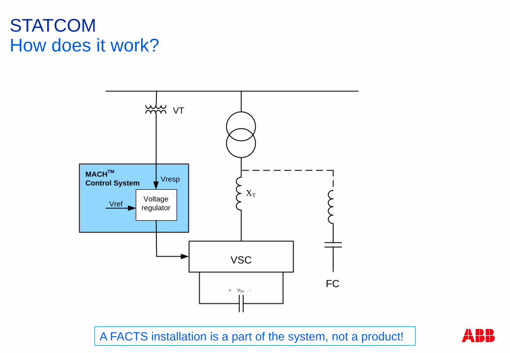
Control System MACH™, regulate and control the SVC.
VSC – Voltage Source Converter Dynamically controlled from full inductive current
to full capacitive current by IGBTs.
Harmonic Filters Capacitors Always connected, if they are needed!
Reduces harmonics generated by the VSC.
Provides capacitive power.
Power Transformer Connects the STATCOM main components to
HV bus.
STATCOM – Static Synchronous CompensatorSingle Line Diagram
+ VDC -
XT
FC
= ~
VSC
A FACTS installation is a part of the system, not a product!
VSC
+ VDC -
XT
FC
Voltage
regulator
Vresp
Vref
MACHTM
Control System
VT
STATCOM How does it work?
A FACTS installation is a part of the system, not a product!

© ABB Group
September 19, 2016 | Slide 22
ABB FACTSMACH™ – Control & Protection
Developed for power system applications More than 400 installations!
Used in SVC, STATCOM, SC, TCSC and HVDC installations.
Designed and tested to meet power systems requirements and standards.
SCADA communication.
Cyber security.
Designed and tested according to international EMC standards.
Usability for high security and safety Modular based design.
User level access for high security and safety.
Detailed supervision of control system, thyristor valves and cooling system.
Graphical programming language for easy understandability.
Powerful debug functionalities with ability to see signals in real time.
HMI with multilanguage selection, Alarm lists and Event lists.
Built in Event Recorder and Transient Fault Recorder (TFR).
Life cycle management Configuration management for reliable handling of revisions.
Reliability Redundancy built in for high reliability.
Service Remote access giving quick assistance from our specialists.
A FACTS installation is a part of the system, not a product!

© ABB Group
September 19, 2016 | Slide 23
ABB FACTS
Typical values for transmission applications:
2-3 forced outages per year
>99% availability (forced)
25 to 30 year design life(typically subsystems such as control and cooling which fail as aging occurs)
SVC and STATCOM – Reliability and Availability
A FACTS installation is a part of the system, not a product!

FACTS - Flexible AC Transmission SystemAgenda
ABB FACTS
What is FACTS?
Dynamic Shunt Compensation – SVC and STATCOM
Series Compensation
How to specify a FACTS installation?
Example of installations – SVC and STATCOM
Example of installations – Series Compensation

FACTS - Flexible AC Transmission SystemSeries Compensation – SC and TCSC
A FACTS installation is a part of the system, not a product!
SC – Fixed Series Capacitor
Capthor™ or gapless design.
One or two fixed SC segments.
TCSC – Thyristor Controlled Series Capacitor
Use of one SC segment, which is fully controllable
by thyristors.
Use of two SC segments, where one segment is
fixed and the other segment is controllable by
thyristors.

© ABB Group
September 19, 2016 | Slide 26
ABB FACTSSeries Capacitor
A FACTS installation is a part of the system, not a product!

© ABB Group
September 19, 2016 | Slide 27
Reduce cost of power transmission due to fewer required lines.
Avoid the need of new transmission lines
Fastest way to increase power transfer capability in the grid
Increase power transfer capability by raising the transient stability limit.
Steady state voltage regulation and raise of voltage collapse limit.
Improve reactive power balance.
Improve voltage profile on transmission line.
Load sharing between parallel circuits and loss reduction.
SSR Mitigation (TCSC).
Detection and damping of active power oscillations (TCSC).
Power flow control (TCSC).
ABB FACTSBenefits of Series Compensation
A FACTS installation is a part of the system, not a product!

© ABB Group
September 19, 2016 | Slide 28
Transmission Line
How to increase transmission capacity?
a) Build an extra power line
b) Series Compensation
ABB FACTS
P1 P1jXL
P2 P2
jXL
jXL
P2jXL
-jXC
P2
Benefits of Series Capacitor – Less transmission lines needed
A FACTS installation is a part of the system, not a product!

© ABB Group
September 19, 2016 | Slide 29
Bypass
DisconnectorIsolating
Disconnector Isolating
Disconnector
MOV
Bypass Switch (Breaker)
Platform Structure
Capacitor
Fast Protective Device
CapThor™
Discharge Current
Limiting & Damping
Equipment
OCT
OCT
OCT
OCT
OCT
ABB FACTS
Capacitor
• Provides capacitive reactance.
MOV (Metal Oxide Varistor)
• Limits the voltage stress across the capacitor immediately
during an excessive line current.
OCT (Optical Current Transducer)
• Measures current.
Fast Protective Device - CapThor™
• Fast bypass of capacitor and MOV that reduces the
amount of MOV.
Bypass Switch (Breaker)
• Bypass of capacitor and MOV.
Discharge Current Limiting & Damping Equipment
• Limits and damps the capacitor discharge current during a
bypass operation.
Bypass and Isolating Disconnectors
• Insulates and bypasses the Series Capacitor during
maintenance and service.
Single Line Diagram – Fixed Series Capacitor with CapThor™
A FACTS installation is a part of the system, not a product!

© ABB Group
September 19, 2016 | Slide 30
ABB FACTSSeries Capacitor – Example of installation
12
4
5
6
1. Capacitor
2. MOV
3. OCT
4. Fast Protective Device -
CapThor™
5. Discharge Current
Limiting & Damping
Equipment
6. Bypass Switch
(Breaker)3
A FACTS installation is a part of the system, not a product!

© ABB Group
September 19, 2016 | Slide 31
ABB FACTSMACH™ – Control & Protection
Developed for power system applications More than 400 installations!
Used in SVC, STATCOM, SC, TCSC and HVDC installations.
Designed and tested to meet power systems requirements and standards.
SCADA communication.
Cyber security.
Designed and tested according to international EMC standards.
Usability for high security and safety Modular based design.
User level access for high security and safety.
Detailed supervision of control system, thyristor valves and cooling system.
Graphical programming language for easy understandability.
Powerful debug functionalities with ability to see signals in real time.
HMI with multilanguage selection, Alarm lists and Event lists.
Built in Event Recorder and Transient Fault Recorder (TFR).
Life cycle management Configuration management for reliable handling of revisions.
Reliability Redundancy built in for high reliability.
Service Remote access giving quick assistance from our specialists.
A FACTS installation is a part of the system, not a product!

© ABB Group
September 19, 2016 | Slide 32
ABB FACTSMACH™ – Control & Protection
There are not any existing conventional protective relays for SC and
TCSC on the market!
Instead, all SC and TCSC suppliers have the protective functions
integrated in the control system!
Examples of protective functions included in MACH™ are:
Capacitor overload protection
Capacitor unbalance protection
Line current supervision
MOV overload protection, High current
MOV overload protection, High energy
MOV overload protection, High
temperature
MOV failure protection
Flashover to platform protection
Main failure protection
CapThor™ protection
Sub harmonic protection
Capacitor discharge function
Bypass switch failure protection, close
failure and open failure
Bypass switch pole disagreement
protection
Bypass switch SF6 gas low density
Disconnector pole disagreement
protection
Backup protection
etc
A FACTS installation is a part of the system, not a product!

© ABB Group
September 19, 2016 | Slide 33
Bypass
DisconnectorIsolating
Disconnector Isolating
Disconnector
MOV
Bypass Switch (Breaker)
Platform Structure
Capacitor
Fast Protective Device
CapThor™
Discharge Current
Limiting & Damping
Equipment
OCT
OCT
OCT
OCT
OCT
MACH™
Control & Protection
Optic Fiber
Optic Fiber
Optic Fiber
Optic Fiber
Optic Fiber
Optic Fiber
ABB FACTSControl & Protection – Fixed Series Capacitor with CapThor™
A FACTS installation is a part of the system, not a product!

© ABB Group
September 19, 2016 | Slide 34
ABB FACTS
Typical values for transmission applications:
1-2 forced outages per year
>99% availability (forced)
25 to 30 year design life
Series Capacitor – Reliability and Availability
A FACTS installation is a part of the system, not a product!

FACTS - Flexible AC Transmission SystemAgenda
ABB FACTS
What is FACTS?
Dynamic Shunt Compensation – SVC and STATCOM
Series Compensation
How to specify a FACTS installation?
Example of installations – SVC and STATCOM
Example of installations – Series Compensation

How to specify a FACTS installation?To be determined by studies and simulations!
Studies are always needed for optimal functionality!
Customer prespecification studies!
Supplier design studies!
Steady State Operation Conditions
Network Stabilty
System contingencies to support
Network short circuits
Line and generator disconnections
Dynamic performance
Grid code
Harmonic performance
Fault ride through
Reactive power balance
Stability
Neqative sequence
Point of connection
A FACTS installation is a part of the system, not a product!

© ABB Group
September 19, 2016 | Slide 37
Specifying SVC (STATCOM & HYBRID)IEEE 1031 - Guide for the Functional Specification
Can be ordered from: http://www.ieee.org/index.html

Studies and ModelingStages to consider for a FACTS project!
Studies for post
commissioning
system operation.
Initial feasability
studies to
determine system
limitations and
needs.
Studies to
determine type of
installation,
location and rating
of installation.
Pre specification
studies.
Pre manufacturing
equipment design
and verification
studies.
Stage 1
Planning
Stage 2
Planning
Stage 3
Performance
Stage 4
Detailed Design
Stage 5
Operation
Customer ABB Customer
Before request
for tender is
submitted!
After request for
tender is
submitted and
during contract
stage!
When the SVC is
in operation!
A FACTS installation is a part of the system, not a product!

Studies and ModelingTypical times for FACTS project development
Project detailed
design,
manufacturing,
shipping, civil
works, installation,
commissioning
Feasability
studies, determine
rating, location,
write specification.
Design studies to
verify that system
and performance
requirements
specified will be
met!
Comparison of
tenders, Q&A,
presentations by
tenderers.
Elaborating details
of commercial
contract
Stage 1-3
Planning
Stage 4a
Tendering
Stage 4b
Evaluation
Stage 4c
Negotiation
Stage 4d
Project delivery
Customer
Approximately 6
months or longer,
depending on
customer internal
processes.
ABB
2-3 months,
depending on
documentation
requirements.
Customer
1-2 months
Customer
1 month
Specification Contract effectiveness PAC
6 12 18 24 30
ABB
Normally 15-18
months, depending
on project
requirements.
A FACTS installation is a part of the system, not a product!

Studies and ModelingStage 1
Stage 1 - To be Performed by Customer Before Request for Tender.
Key Objectives
Identify Power System Characteristics and
System Performance Problems such as
Transient Instability
Oscillatory Instability
Steady State Instability
Short-Term Voltage Collapse
Powerflow and Thermal Rating
Reinforcement Needs
Fast vs. Slow
Shunt Compensation vs. Series Compensation

Studies and ModelingStage 2
Stage 2 - To be Performed by Customer Before Request for Tender.
Key Objectives
Identify Solution Options
Evaluate Performance of Solution Options
Other Considerations
Location
Loss Evaluation
Availability and Reliability
Potential interaction with other devises
etc
Economics of the solution options vs. value of system benefits

Stage 3 - To be Performed by Customer Before Request for Tender.
Key Objectives
Provide Technical Basis and Input to
the Technical Specification and RFP
Define SVC/STATCOM Mvar and PCC Voltage
Define Loss Evaluation Criteria and Penalties
Define Harmonic Performance Requirements
Define PCC Harmonic Impedance
Define RAM Requirements based on System
Operation Constraints
Define Audible Sound Requirements
Studies and ModelingStage 3

Studies and ModelingStage 3 – Example, Frequency Scanning
Stage 3 - Example, to be Performed by Customer Before Request for Tender.
Main Scenarios Summer Light, Summer Peak, Winter Light and Winter Peak
10 to100 contingencies in each scenario
200 400 600 800 1000 12000
0.5
1
1.5
2
2.5
Netw
ork
Resis
tance [
pu]
Frequency [Hz]
Summer Peak Base Case
200 400 600 800 1000 1200-1.5
-1
-0.5
0
0.5
1
1.5
Netw
ork
Reacta
nce [
pu]
Frequency [Hz]
SIMPOW LOMOD=S
SIMPOW LOMOD=P
HSPEC
0.1 0.15 0.2 0.25 0.3
-0.3
-0.25
-0.2
-0.15
-0.1
-0.05
1
2
3
4
5
6
7
8
9
Woree SVC, Summer Peak, Netw ork Impedance, N=3
Resistance [pu]
Reacta
nce [pu]

Stage 4 - To be Performed by ABB when Received Request
for Tender and/or during Contract stage.
Key Objectives
To verify that system and performance
requirements specified is meet!
Detailed design for equipment
manufacturing and procurement
Control and Protection
Insulation Coordination
Power Electronics
Filters
Main Circuit Equipment
Main Transformer, Reactors,
Capacitors, CT, VT etc
Studies and ModelingStage 4
Studies
Pre-Manufacturing Equipment Design
and Verification Studies
Main Circuit Equipment Design and Rating
Dynamic Performance
Harmonic Performance & Filter Design
Transient, Dynamic and Over Voltage
Analysis
Control performance
Insulation Coordination
Audible Sound
Magnetic Field
etc

Stage 4 - Example, to be Performed by ABB when Received
Request for Tender and/or during Contract stage.
Woree 132 kV
Znet
(j)
TCR5th Harmonic
Filter
ITCR
TSC 7th Harmonic
Filter
11th Harmonic
Filter
ZT
Studies and ModelingStage 4 – Example, Harmonic Performance Calculation
0.02 0.04 0.06 0.08 0.1 0.12 0.14 0.16 0.18 0.2
-0.06
-0.04
-0.02
0
0.02
0.04
0.06
0.08
0.1
1
2
3
4
5
6
7
8
9
Woree SVC, Winter Peak, Netw ork Impedance, N=5
Resistance [pu]
Reacta
nce [pu]
0.1 0.15 0.2 0.25 0.3
-0.3
-0.25
-0.2
-0.15
-0.1
-0.05
1
2
3
4
5
6
7
8
9
Woree SVC, Summer Peak, Netw ork Impedance, N=3
Resistance [pu]
Reacta
nce [pu]
-0.2 0 0.2 0.4 0.6 0.8 1 1.2
-0.4
-0.2
0
0.2
0.4
0.6
0.8
1
2
3
4
5
Woree SVC, Summer Peak, Netw ork Impedance, N=25
Resistance [pu]
Reacta
nce [pu]
Zt
ZNZFC5
ITCR
UN
+
-
IN
ZFC7ZFC11

Studies and ModelingStage 5
Stage 5 - To be Performed by Customer when
SVC/STATCOM is in operation.
Key Objectives
Customer to determine tests and studies.
FACTS - Flexible AC Transmission SystemAgenda
ABB FACTS
What is FACTS?
Dynamic Shunt Compensation – SVC and STATCOM
Series Compensation
How to specify a FACTS installation?
Example of installations – SVC and STATCOM
Example of installations – Series Compensation

Example of InstallationsFrance – Dynamic Control of 225 kV Power Transmission
Background: Rapidly increased power demand in the region of Brittany.
Only about 5% of the power consumption is generated within the region.
Remote power plants connected through long and heavily loaded 400 kV and 225 kV lines.
Voltage stability a major issue, especially in the cities of Lorient and Saint Brieuc.
Solution:
Provide fast supply of reactive power upon the appearance of
faults in the grid.
Absorb reactive power to control the grid voltage during low
load or high level of distributed generation.
Prevent tripping of wind farms located in the region.
Two SVCs connected to 225 kV
Close to the town of Lorient
Poteau Rouge SVC
100 Mvar inductive to 200 Mvar capacitive
Close to the town of Saint Brieuc
Plaine Haute SVC
50 Mvar inductive to 100 Mvar capacitive

Example of InstallationsMongolia - Voltage Support for Oyu Tolgoi Gold Mine
Customer need
Support the load at outage of one of the feeding 220 kV lines for
Prevent excessive system over voltages at large load rejections
ABB solution
2 parallel SVCs rated +/-100 Mvar connected to the 220 kV grid
Special undervoltage strategy ensuring that the SVC never disconnects during an undervoltage.
Negative phase sequence control reduces unbalances between the phasees of the 220 kV system in case of short single-phase line faults.
Customer value
A flexible solution capable of stabilizing the power supply at many different events
High availability and reliability
A system adapted for planned future expansions
100 MVA
220 kV
TCR
100 Mvar
TCR
100 Mvar11th
10 Mvar
5th
71 Mvar7th
19Mvar
100 MVA
220 kV
TCR
100 Mvar
TCR
100 Mvar11th
10 Mvar
5th
71 Mvar7th
19Mvar

Background:
An increasing demand for power within the country’s economy.
Increasing opposition to constructing new power transmission lines.
A demand for better utilization of existing facilities.
Solution:
A STATCOM installed at Cerro Navia in the Central Interconnected System, the largest power system in Chile.
Rating
220 kV, 65 Mvar Inductive to 140 Mvar Capacitive.
VSC +/-102.5 Mvar
Filter 37.5 Mvar
Purpose:
Increase the power transfer from south Chile up to the capital of Santiago over the long power corridor.
Yield dynamic voltage control for steady-state and transient grid conditions.
Contribute reactive power during faults in the grid.
Example of InstallationsChile – STATCOM for Improved Transmission Capability

© ABB Group
September 19, 2016 |
Example of InstallationsUSA – STATCOM for Improved Power Quality
Background:
The power quality needs to be improved in the Alabama Power grid .
The Steel manufacturer SSAB must reduceharmonics, reduce flicker and improve power factor.
Solution:
A SVC-Light® (STATCOM) using multi-level VSC installed in Alabama 2015.
Rating -58/+220 Mvar
Purpose:
Improved Power Quality
Reduced harmonics
Reduced flicker
Improved power factor (cos ).
More active power could be used in the steelmanufcturing process.
Increased production
Lower production cost

© ABB Group
September 19, 2016 |
ABB FACTS References - East Asia (except CHINA)KEPCO
SEO-DAEGU
-100/+100 Mvar
345 kV
SAMMI STEEL
KOREA
0/+80 Mvar
30 kV
HANBO STEEL
DANGJIN-KUN5 X 0/+80 & 0/+90 Mvar
22kV & 33 kV
POHANG IRON & STEEL
KWANG YANG WORKS
0/+83 Mvar
22 kV
POSCO STAINLESS
POHANG
0/+120 Mvar
22 kV
KOHEMA
KONSAN
0/+90 Mvar
22 kV
MINING CORP.
MAYMYO
0/+15 Mvar
33 kV
EGAT
THA TAKO I & II
2 x -125/+25 Mvar
500 kV
NAKORNTHAI STRIP MILL
CHONBURI0/+160, 0/+110 & 0/+55 Mvar
33, 22 & 33 kV
SIAM CONSTR.
RAYONG
0/+110 Mvar
22 kV
NEB
KL NORTH I & II2 x -100/+100 Mvar
275 kV
MEGASTEEL
0/+95, 0/+190 &
0/+46Mvar
33 kV
ANTARA STEEL
PASIR GUDANG
0/+110 Mvar
30 kV
BARATA
SURABAYA
0/+4 Mvar
6 kV
NATSTEEL
SINGAPORE
0/+58 Mvar
22 kV
KAN WON IDUST.
POHANG
0/+115 Mvar
22 kV
POSCO IRON
& STEEL, POHANG
0/+105 Mvar
22 kV
POSCO SPECIAL STEEL
0/+95 Mvar
30 kV
CHIN TAI STEEL
KAOHSIUNG
0/+75 Mvar
22 kV
SSF STEEL
-34.2/+45.8 Mvar
23 kV
TUNG HO STEEL I & II
TAO YUAN
0/+90 Mvar, 0/+165 Mvar
22 kV, 33 kV
LO TOUN STEEL & IRON
LO TUON
0/+125 Mvar
23 kV
HAI -KWANG ENTERPRICE
HAI-KWANG
0/+65 Mvar
23 kV
SIAM IRON & STEEL
BANGKOK
0/+50 Mvar
11 kV
SIAM YAMOTO STEEL
SVC-L
0/+120 Mvar
22 kV
EGAT
BANG SAPHAN
-50/+300 Mvar
230 kV
EGAT
CHUMPON
-20/+60 Mvar
115 kV
NEB
YONG PENG
-100/+100 Mvar
275 kV
UMC METALS Ltd
UNION METAL
0/+60 Mvar, 22 kV
PUB
LABRADOR
-50/0 Mvar
230 kV
PUB
KALLANG BASIN
-100/0 Mvar
230 kV
RIO TINTO
OYU TOLGOI
2 x -100/+100 Mvar
220 kV
TAN DINH SC
101 Mvar
500 kV
FACTS - Flexible AC Transmission SystemAgenda
ABB FACTS
What is FACTS?
Dynamic Shunt Compensation – SVC and STATCOM
Series Compensation
How to specify a FACTS installation?
Example of installations – SVC and STATCOM
Example of installations – Series Compensation

Background• Hydro power to be transmitted from the Comahue
region in south western Argentina to the large
consumer areas around Buenos Aires.
• Transener´s 500 kV AC power transmission corridor
has a distance of more than 1000 km.
• Increase of active power transmission capability
needed.
Solution
• Four parallel 500 kV AC lines, all series
compensated.
• Four SC totally rated 430 Mvar.
Benefits
• Transmision capacity increased by 1300MW to 4600
MW.
• Less lines needed.
• Improved transient stability.
• Improved active power sharing between the lines.
Example of SC InstallationsArgentina – 500 kV Series Capacitors

© ABB Group
September 19, 2016 |
Tan Dinh Series CapacitorVietnam
An ABB Series Capacitor installed in
the Tan Dinh substation at the
southern end of the 500 kV power
transmission corridor stretching
between the north and the south of
Vietnam.
The purpose of the SC is improving
the power transmission capability of
the very long corridor.
Series Capacitor rating: 101 Mvar at
500 kV.
The project was undertaken together
with ABB Substations, who also
supplied high voltage apparatus for
220 kV and 500 kV.
Series Capacitor

Background
• The Cape Corridor is a portion of the
transmission network that stretches from
Mpumalanga down to the Western Cape,
approximately 1400 km.
• Increased power transmission capacity to
the Cape region, will allow more flexibility
and reduce reliance on existing local
power generation.
• Installing of Series Compensation will
decrease the need for new lines.
Solution
• A total of six series capacitors with
Capthor™ (fast protective device) was
installed in the 765 kV national grid in
South Africa.
• The six series capacitors are located at
four sites along the Cape (see figure) • Alpha 1 & 2, each rated at 446 Mvar
• Beta 1 & 2, each rated at 1340 Mvar
• Perseus, rated at 893 Mvar
• Mercury, rated at 1119 Mvar
Example of SC InstallationsSouth Africa - 765 kV Series Capacitors

Example of Installations N/S project – Eletronorte, Brasil
Eletronorte’s need• 1200 km (750 miles) interconnection of
Eletronorte’s (North) and Furnas’ (South) 500 kV
power systems, without power oscillations.
ABB’s response• 5 FSC and 1 TCSC
• Marabá SC rated 348 Mvar
• Colinas SC rated 2x161 Mvar
• Miracena SC rated 161 Mvar
• Imperatriz SC rated 161 Mvar
• Imperatriz TCSC rated 107 Mvar
Eletronorte’s benefits• Single-line AC interconnection with TCSC with
POD (Power Oscillation Damper) functions to
mitigate power oscillations.
Brazil
North-South
Interconnection
5 SCs + 1 TCSC
0 10 20 30 40 50 60 70 800
100
200
300
400
500
600
700
800
900
1000
time (sec)
Pline (
MW
)
No TCSC POD active
0 10 20 30 40 50 60 70 800
100
200
300
400
500
600
700
800
900
1000
time (sec)
Pline (
MW
)
Both TCSC PODs active

© ABB Group
September 19, 2016 | Slide 58