lecture ee333 - lecture 9 - clarkson universitylwu/ee333/lectures/lecture...lecture 9 transmission...
TRANSCRIPT

Lecture 9
Transmission Line Parameters
Reading: 4.1 – 4.6 ; 4.8 – 4.10
Homework 3 – will be posted on the course website
Dr. Lei Wu
Department of Electrical and Computer Engineering
EE 333
POWER SYSTEMS ENGINEERING

Outline
Develop simple model for transmission lines
Line resistance
Line conductance
Line inductance
Line capacitance
Analyze how the geometry of the transmission lines will affect the model parameters
2

Primary Methods for Power Transfer
The most common methods for transfer of electric power are
Overhead ac
Underground ac
Overhead dc
Underground dc
Others
3

Transmission line voltage structure
Extra-high-voltage lines Voltage: 345 kV, 500 kV, 765 kV
Interconnection between systems
High-voltage lines Voltage: 115 kV, 230 kV
Interconnection between substations, power plants
Sub-transmission lines Voltage: 46 kV, 69 kV
Interconnection between substations and large industrial customers
Distribution lines Voltage: 2.4 kV to 46 kV, with 15 kV being the most commonly used
Supplies residential and commercial customers
High-voltage DC lines Voltage: ±120 kV to ±600 kV
Interconnection between regions (e.g., Oregon-California)
4

Transmission line
Three-phase conductors, which carry the electric current
Insulators, which support and electrically isolate the conductors
Tower, which holds the insulators and conductors
Foundation and grounding
Optional shield conductors, which protect against lightning
5

Transmission line
Shieldconductor
Insulator
Phaseconductor
Tower
69kVLine
CompositeInsulatorCrossarm
Compositeinsulator
Steel tower
Twoconductor
bundle
Shield conductor
6

Distribution line
Double circuit69 kV line
Distribution line12.47kV
Wooden tower
Shieldconductor
240V/120Vinsulated line
Transformers
Fuse cutout
Surge arrester
Insulator
7

Transmission line parameter calculation
Characteristics parameters (per unit length)
Series resistance (R)
Shunt conductance (G)
Series inductance (L)
Shunt capacitance (C)
R L
CG
8

Transmission line parameter calculation
Data needed for calculation
Conductor type
Conductor diameter and GMR
Number of conductors per bundle
Bundle spacing
Distance between phases
9
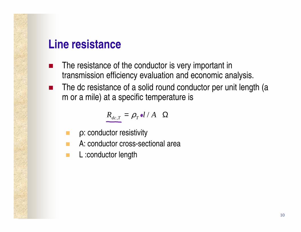
Line resistance
The resistance of the conductor is very important in transmission efficiency evaluation and economic analysis.
The dc resistance of a solid round conductor per unit length (a m or a mile) at a specific temperature is
ρ: conductor resistivity
A: conductor cross-sectional area
L :conductor length
, /dc T TR l Aρ= Ωi
10

Line resistance Example
What is the dc resistance (in Ω/mile) of a 1’’ diameter solid
aluminum wire?
1’’=2.54cm=0.0254meter
1 mile = 1609.344 meter
8min
, 22
1 2.65 10 1609.344 /0.084 /
0.02542
alu umdc T
m m mileR mile
Am
ρ
π
− Ω= = = Ω
i i i
i
8min 2.65 10alu um mρ −= Ωi
11

Line resistance
Stranded conductors are longer than corresponding
transmission line, thus higher resistance
Because ac current tends to flow towards the surface of a
conductor (skin effect), the ac resistance of a line is slightly
higher than the dc resistance.
Resistivity and hence line resistance increase as conductor
temperature increases.
22 1
1T T
T T
T Tρ ρ +
=+
12

Line conductance
Conductance accounts for real power loss between conductors or between conductors and ground. For overhead lines, this power loss is due to leakage currents at
insulators and to corona.
Conductance is usually neglected in power system studies. Losses due to insulator leakage and corona are usually small
compared to conductor I2R loss.
It is a very small component of the shunt admittance.
13

Line inductance
A conductor carrying current produces a magnetic field around
the conductor.
The relationship between current I and magnetic flux linkage λis represented by the inductance
IL
λ=
14

Line inductance
For a solid cylindrical conductor
0 ln2 '
DL
I r
µλπ
= =
0 00.25
ln ln2 2 '
D DIL I I
re r
µ µλπ π−= = =
70where 4 *10 H/m:permeability of free spaceµ π −=
15

Line inductance
For an array of M solid cylindrical conductor
Assume that the sum of the conductor currents is zero
The flux linking conductor k to P
due to current Ik
The flux linking conductor k to P
due to current Im
The total flux linking conductor k in an array of M conductors
0
1, 1
1ln where '
2
M M
k kPi i kki P i ik
I D rD
µλ λπ= →∞ =
= = =∑ ∑
0M
ii
I =∑
16
0 ln2 '
PkkPk k
k
DI
r
µλπ
=
0 ln2
PmkPm m
km
DI
D
µλπ
=

Line inductance
Single-phase two-wire line
0 ln2 '
x xx
x x
DL
I I r
λ λ µπ
= = =
0 ln2 '
y yy
y y
DL
I I r
λ λ µπ
= = =−
20 0 0 0ln ln ln ln
2 ' 2 ' 2 ' ' ' 'x y
x y x y x y
D D D DL L L
r r r r r r
µ µ µ µπ π π π
= + = + = =
17

Line inductance
Three-phase three-wire line
( )
0
0
0 0
1 1 1ln ln ln
2 '
1 1ln ln
2 '
1 1ln ln ln
2 ' 2 '
a a b ca
a b ca
a a aa a
I I Ir D D
I I Ir D
DI I I
r D r
µλπ
µπ
µ µπ π
= + +
= + +
= − =
0 ln2 'a
a
DL
r
µπ
=
18

Line inductance
General formula for calculating inductance
0 ln2
where GMD: geometric mean distance
GMR: geometric mean radius
GMDL
GMR
µπ
=
19

Line inductance
General formula for calculating inductance
0 ln2
xyx
xx
GMDL
GMR
µπ
=
0 ln2
yxy
yy
GMDL
GMR
µπ
=
x yL L L= +
20

Line inductance
GMR
( )( ) ( )2
11 12 1 21 22 2 1 2
ii
ij
where D ' 0.7788
D =distance between conductors i and j
nn n n n nn
i i
GMR D D D D D D D D D
r r
=
= =
⋯ ⋯ ⋯ ⋯
21

Line inductance
For symmetrical configurations
11 12 1n
nGMR D D D= ⋯
( )( )( )3 33 11 12 13 0.7788 2 2 1.4605GMR D D D r r r r= = =
( )( )( )( )4 44 11 12 13 14 0.7788 2 2 2 2
2.0654
GMR D D D D r r r r
r
= =
=
22