lecture 9 resistors in series and parallel kirchoff’s laws household circuits
TRANSCRIPT
Lecture 9
Resistors in series and parallel Kirchoff’s laws Household circuits
Fig. Q18-13, p.616
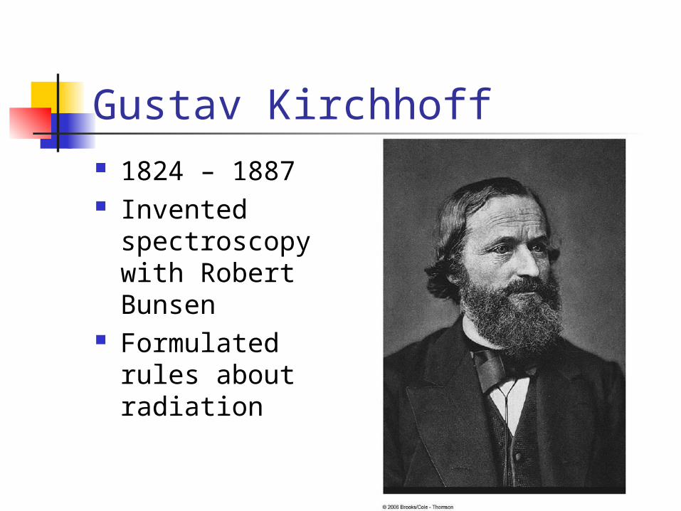
Gustav Kirchhoff 1824 – 1887 Invented
spectroscopy with Robert Bunsen
Formulated rules about radiation
Kirchhoff’s Rules There are ways in which resistors
can be connected so that the circuits formed cannot be reduced to a single equivalent resistor
Two rules, called Kirchhoff’s Rules can be used instead
Statement of Kirchhoff’s Rules Junction Rule
The sum of the currents entering any junction must equal the sum of the currents leaving that junction
A statement of Conservation of Charge
Loop Rule The sum of the potential differences across
all the elements around any closed circuit loop must be zero
A statement of Conservation of Energy
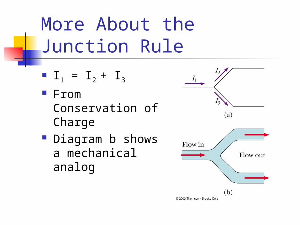
More About the Junction Rule I1 = I2 + I3 From
Conservation of Charge
Diagram b shows a mechanical analog
Setting Up Kirchhoff’s Rules Assign symbols and directions to the
currents in all branches of the circuit If a direction is chosen incorrectly, the
resulting answer will be negative, but the magnitude will be correct
When applying the loop rule, choose a direction for transversing the loop Record voltage drops and rises as they
occur
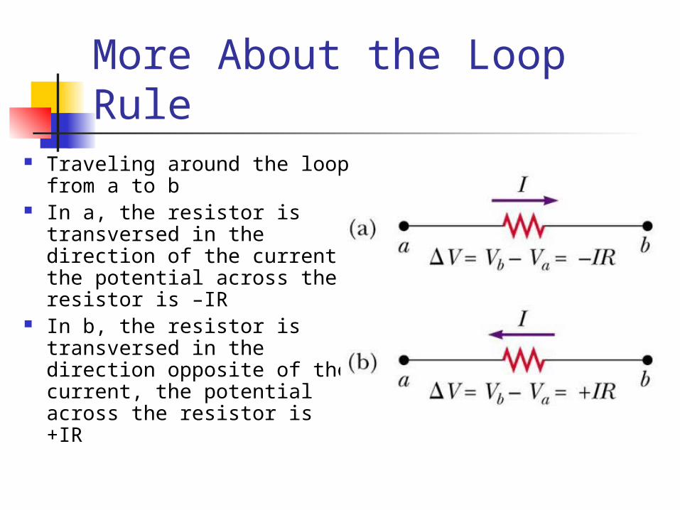
More About the Loop Rule Traveling around the loop
from a to b In a, the resistor is
transversed in the direction of the current, the potential across the resistor is –IR
In b, the resistor is transversed in the direction opposite of the current, the potential across the resistor is +IR
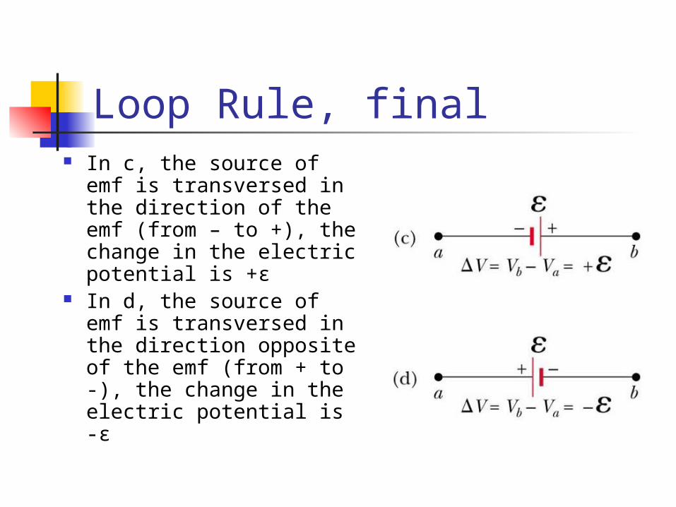
Loop Rule, final In c, the source of emf
is transversed in the direction of the emf (from – to +), the change in the electric potential is +ε
In d, the source of emf is transversed in the direction opposite of the emf (from + to -), the change in the electric potential is -ε
Junction Equations from Kirchhoff’s Rules Use the junction rule as often as
needed, so long as, each time you write an equation, you include in it a current that has not been used in a previous junction rule equation In general, the number of times the junction
rule can be used is one fewer than the number of junction points in the circuit
Loop Equations from Kirchhoff’s Rules The loop rule can be used as often
as needed so long as a new circuit element (resistor or battery) or a new current appears in each new equation
You need as many independent equations as you have unknowns
Problem-Solving Strategy – Kirchhoff’s Rules
Draw the circuit diagram and assign labels and symbols to all known and unknown quantities
Assign directions to the currents. Apply the junction rule to any junction in the
circuit Apply the loop rule to as many loops as are
needed to solve for the unknowns Solve the equations simultaneously for the
unknown quantities Check your answers
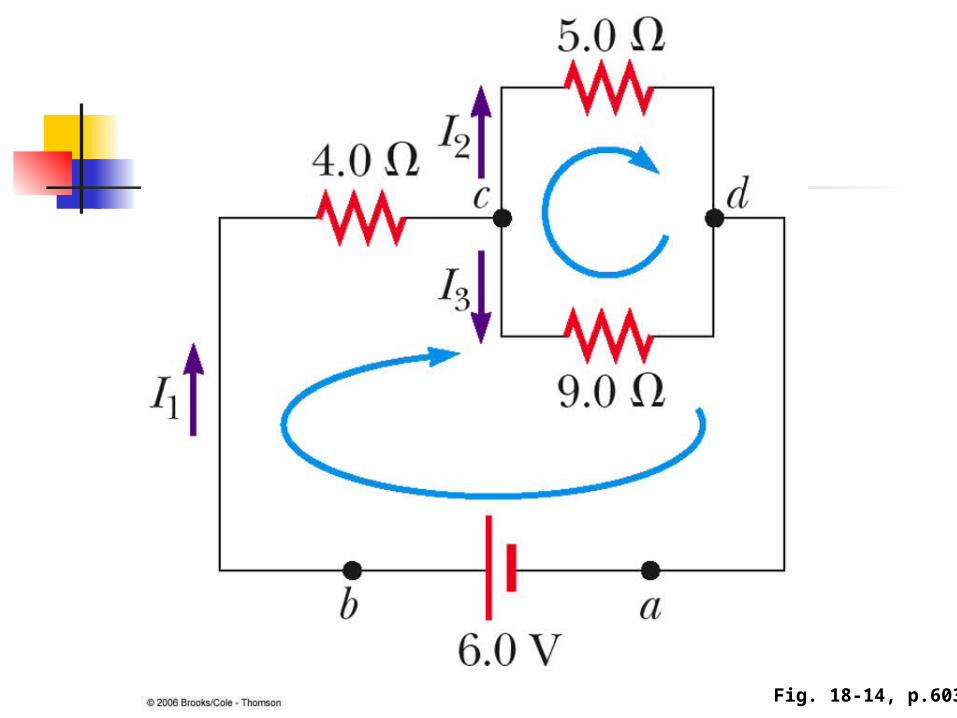
Fig. 18-14, p.603

Fig. P18-60, p.622
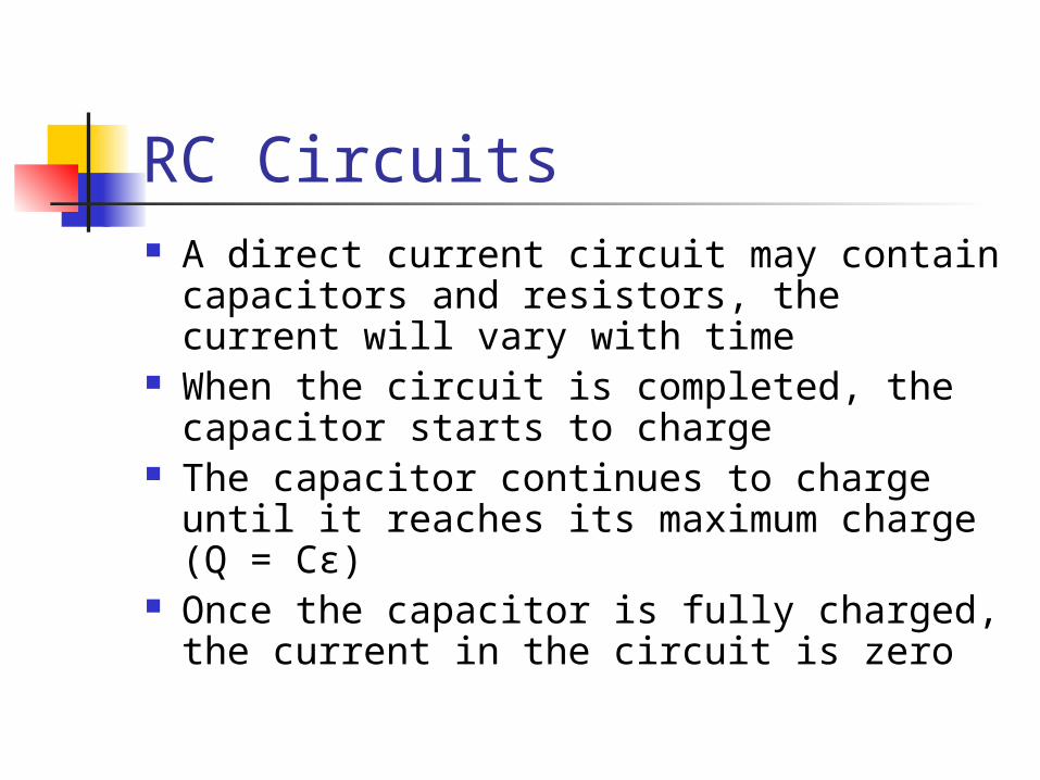
RC Circuits A direct current circuit may contain
capacitors and resistors, the current will vary with time
When the circuit is completed, the capacitor starts to charge
The capacitor continues to charge until it reaches its maximum charge (Q = Cε)
Once the capacitor is fully charged, the current in the circuit is zero
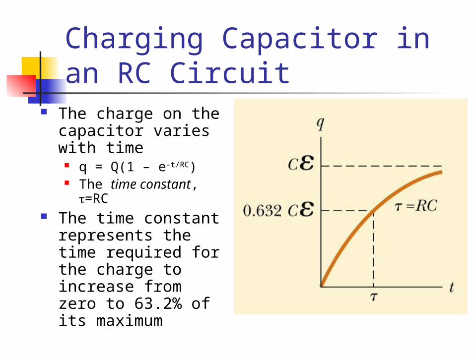
Charging Capacitor in an RC Circuit
The charge on the capacitor varies with time
q = Q(1 – e-t/RC) The time constant,
=RC The time constant
represents the time required for the charge to increase from zero to 63.2% of its maximum
Notes on Time Constant In a circuit with a large time
constant, the capacitor charges very slowly
The capacitor charges very quickly if there is a small time constant
After t = 10 , the capacitor is over 99.99% charged
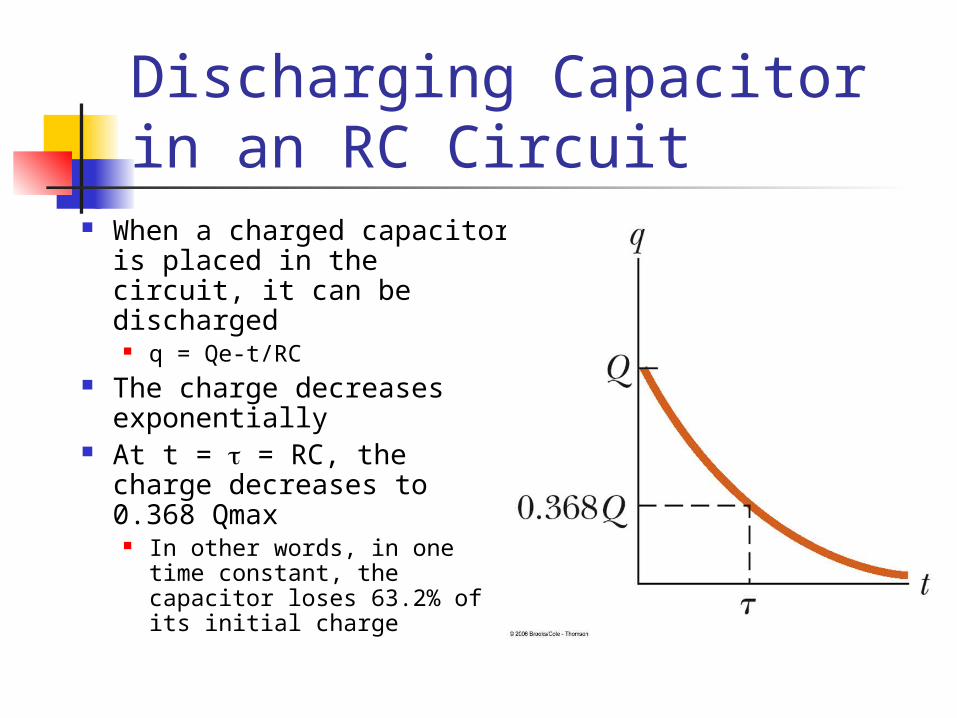
Discharging Capacitor in an RC Circuit
When a charged capacitor is placed in the circuit, it can be discharged
q = Qe-t/RC The charge decreases
exponentially At t = = RC, the charge
decreases to 0.368 Qmax In other words, in one time
constant, the capacitor loses 63.2% of its initial charge
Demo 1 Demo 2
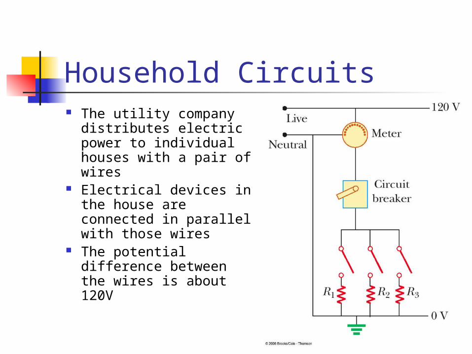
Household Circuits The utility company
distributes electric power to individual houses with a pair of wires
Electrical devices in the house are connected in parallel with those wires
The potential difference between the wires is about 120V
Household Circuits, cont. A meter and a circuit breaker are
connected in series with the wire entering the house
Wires and circuit breakers are selected to meet the demands of the circuit
If the current exceeds the rating of the circuit breaker, the breaker acts as a switch and opens the circuit
Household circuits actually use alternating current and voltage
Electrical Safety Electric shock can result in fatal burns Electric shock can cause the muscles of
vital organs (such as the heart) to malfunction
The degree of damage depends on the magnitude of the current the length of time it acts the part of the body through which it passes

Effects of Various Currents 5 mA or less
Can cause a sensation of shock Generally little or no damage
10 mA Hand muscles contract May be unable to let go a of live wire
100 mA If passes through the body for just a few
seconds, can be fatal
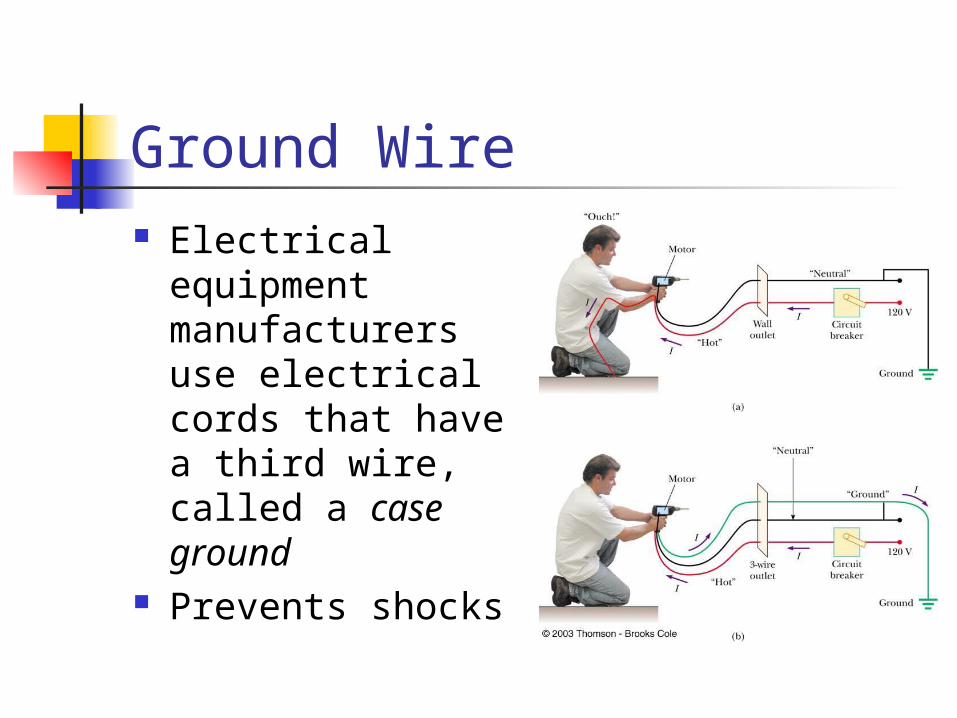
Ground Wire Electrical
equipment manufacturers use electrical cords that have a third wire, called a case ground
Prevents shocks
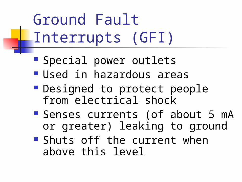
Ground Fault Interrupts (GFI) Special power outlets Used in hazardous areas Designed to protect people from
electrical shock Senses currents (of about 5 mA or
greater) leaking to ground Shuts off the current when above
this level
Fig. 18-21, p.610
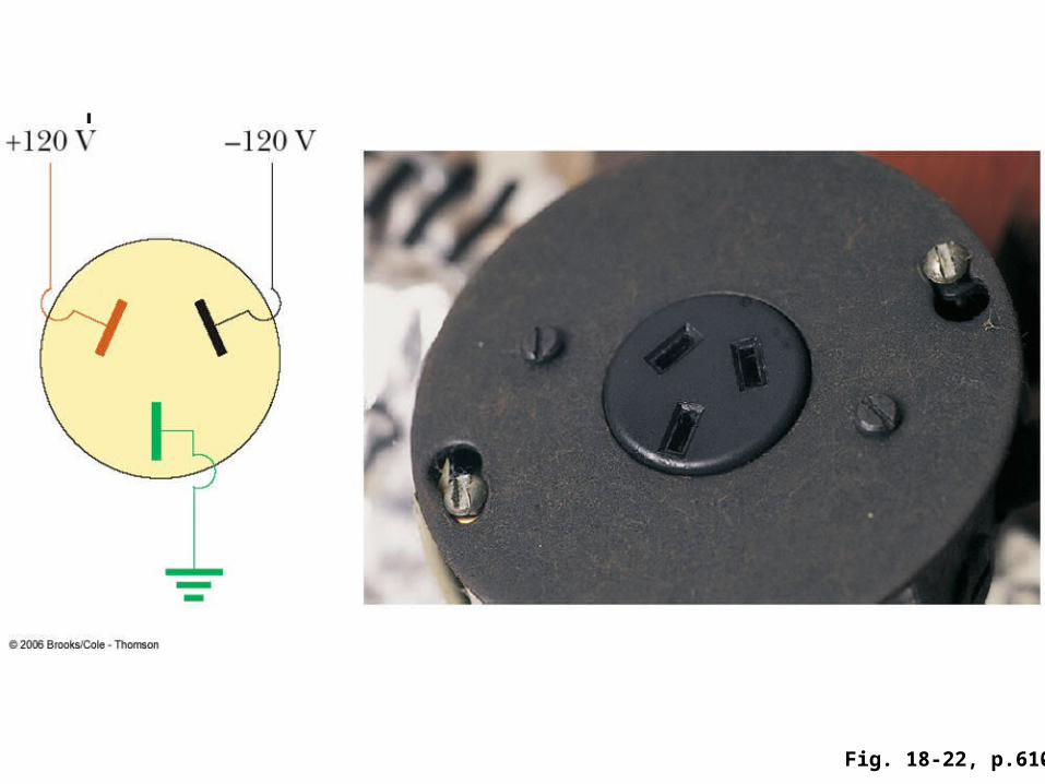
Fig. 18-22, p.610
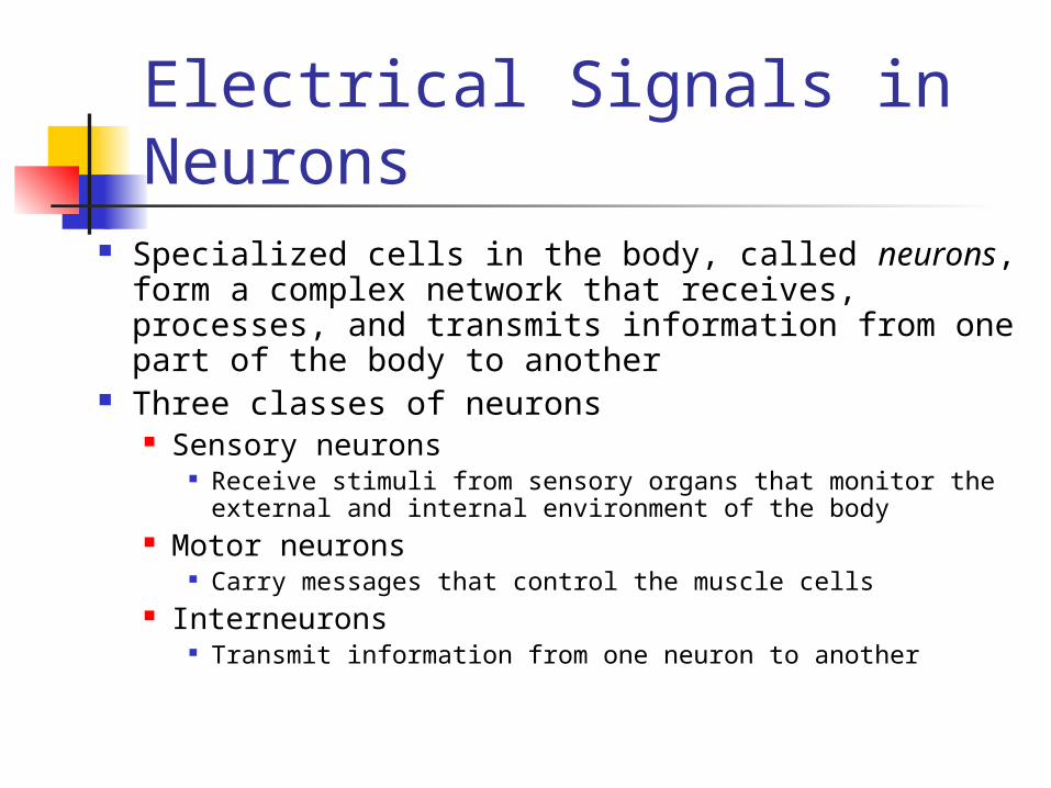
Electrical Signals in Neurons
Specialized cells in the body, called neurons, form a complex network that receives, processes, and transmits information from one part of the body to another
Three classes of neurons Sensory neurons
Receive stimuli from sensory organs that monitor the external and internal environment of the body
Motor neurons Carry messages that control the muscle cells
Interneurons Transmit information from one neuron to another
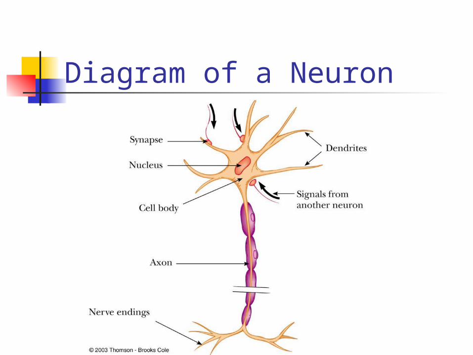
Diagram of a Neuron
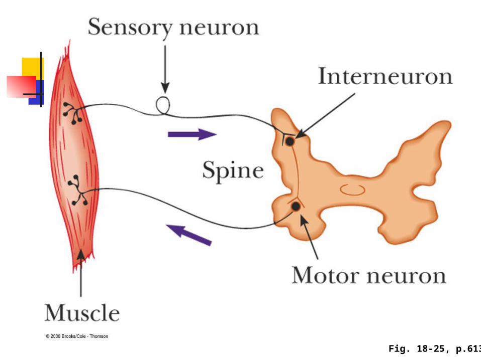
Fig. 18-25, p.613
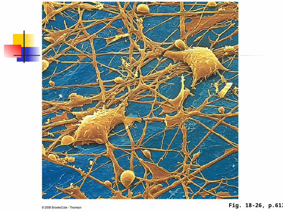
Fig. 18-26, p.613
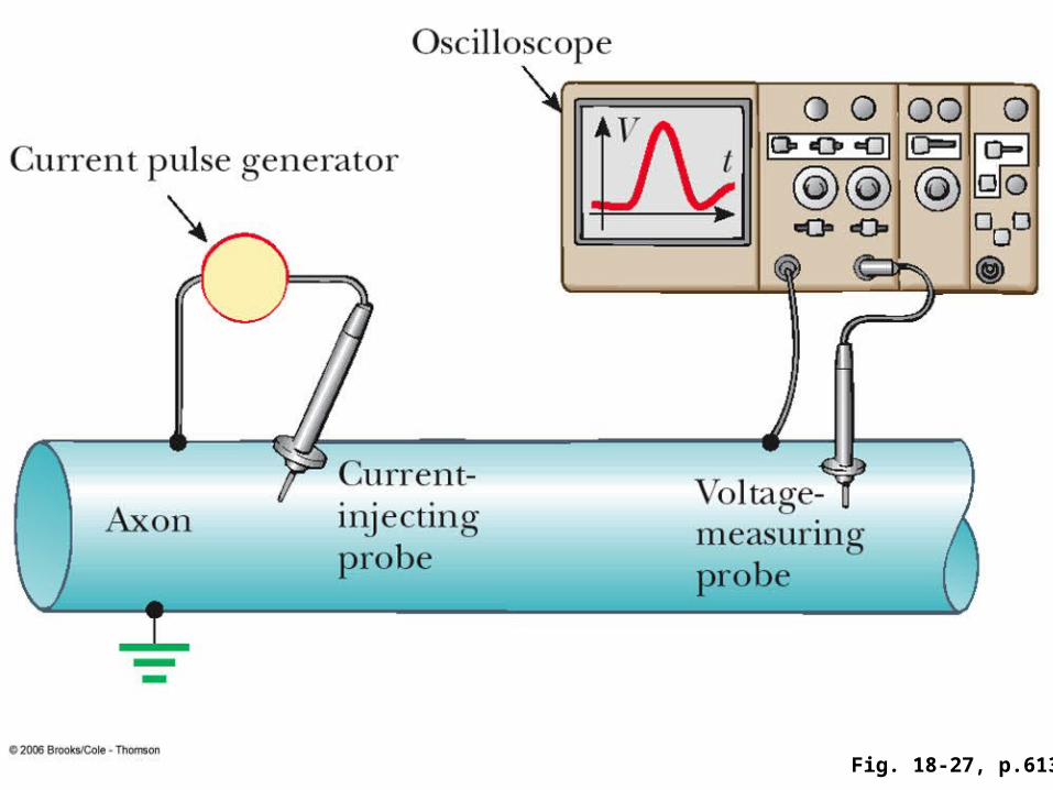
Fig. 18-27, p.613